BVPS-2 UFSAR Rev. 15 7-i CHAPTER 7 TABLE OF CONTENTS Section Title Page 7 INSTRUMENTATION AND CONTROLS ...................... 7.1-1 7.1 INTRODUCTION ...................................... 7.1-1 7.1.1 Identification of Safety-Related Systems .......... 7.1-3 7.1.2 Identification of Safety Criteria ................. 7.1-4 7.1.3 References for Section 7.1 ........................ 7.1-23 7.2 REACTOR TRIP SYSTEM ............................... 7.2-1 7.2.1 Description ....................................... 7.2-1 7.2.2 Analyses .......................................... 7.2-18 7.2.3 Tests and Inspections ............................. 7.2-35 7.2.4 References for Section 7.2 ........................ 7.2-35 7.3 ENGINEERED SAFETY FEATURES ACTUATION SYSTEM ....... 7.3-1 7.3.1 Description ....................................... 7.3-1 7.3.2 Analysis .......................................... 7.3-10 7.3.3 References for Section 7.3 ........................ 7.3-25 7.4 SYSTEMS REQUIRED FOR SAFE SHUTDOWN ................ 7.4-1 7.4.1 Description ....................................... 7.4-2 7.4.2 Analysis .......................................... 7.4-7 7.4.3 References for Section 7.4 ........................ 7.4-9 7.5 SAFETY-RELATED DISPLAY INSTRUMENTATION ............ 7.5-1 7.5.1 Introduction ...................................... 7.5-1 7.5.2 Description of Information Systems ................ 7.5-1 7.5.3 Description of Variables .......................... 7.5-13 7.5.4 Additional Information ............................ 7.5-16 7.5.5 Bypass and Inoperable Status Indication ........... 7.5-17 7.5.6 Safety Parameter Display System ................... 7.5-19 7.5.7 References for Section 7.5 ........................ 7.5-20 7.6 ALL OTHER SYSTEMS REQUIRED FOR SAFETY ............. 7.6-1 7.6.1 Instrumentation and Control Power Supply System...7.6-1 7.6.2 Residual Heat Removal Isolation Valves ............ 7.6-2 7.6.3 Refueling Interlocks .............................. 7.6-4 7.6.4 Accumulator Motor-Operated Valves ................. 7.6-4 7.6.5 Switchover from Injection to Recirculation ........ 7.6-6 7.6.6 Reactor Coolant System Loop Isolation Valve Interlocks Description ............................ 7.6-6

Welcome message from author
This document is posted to help you gain knowledge. Please leave a comment to let me know what you think about it! Share it to your friends and learn new things together.
Transcript
BVPS-2 UFSAR Rev. 15
7-i
CHAPTER 7
TABLE OF CONTENTS Section Title Page 7 INSTRUMENTATION AND CONTROLS......................7.1-1 7.1 INTRODUCTION......................................7.1-1 7.1.1 Identification of Safety-Related Systems..........7.1-3 7.1.2 Identification of Safety Criteria.................7.1-4 7.1.3 References for Section 7.1........................7.1-23 7.2 REACTOR TRIP SYSTEM...............................7.2-1 7.2.1 Description.......................................7.2-1 7.2.2 Analyses..........................................7.2-18 7.2.3 Tests and Inspections.............................7.2-35 7.2.4 References for Section 7.2........................7.2-35 7.3 ENGINEERED SAFETY FEATURES ACTUATION SYSTEM.......7.3-1 7.3.1 Description.......................................7.3-1 7.3.2 Analysis..........................................7.3-10 7.3.3 References for Section 7.3........................7.3-25 7.4 SYSTEMS REQUIRED FOR SAFE SHUTDOWN................7.4-1 7.4.1 Description.......................................7.4-2 7.4.2 Analysis..........................................7.4-7 7.4.3 References for Section 7.4........................7.4-9 7.5 SAFETY-RELATED DISPLAY INSTRUMENTATION............7.5-1 7.5.1 Introduction......................................7.5-1 7.5.2 Description of Information Systems................7.5-1 7.5.3 Description of Variables..........................7.5-13 7.5.4 Additional Information............................7.5-16 7.5.5 Bypass and Inoperable Status Indication...........7.5-17 7.5.6 Safety Parameter Display System...................7.5-19 7.5.7 References for Section 7.5........................7.5-20 7.6 ALL OTHER SYSTEMS REQUIRED FOR SAFETY.............7.6-1 7.6.1 Instrumentation and Control Power Supply System...7.6-1 7.6.2 Residual Heat Removal Isolation Valves............7.6-2 7.6.3 Refueling Interlocks..............................7.6-4 7.6.4 Accumulator Motor-Operated Valves.................7.6-4 7.6.5 Switchover from Injection to Recirculation........7.6-6 7.6.6 Reactor Coolant System Loop Isolation Valve Interlocks Description............................7.6-6
BVPS-2 UFSAR Rev. 13
7-ii
TABLE OF CONTENTS (Cont) Section Title Page 7.6.7 Interlocks for RCS Pressure Control during Low Temperature Operation.............................7.6-7 7.7 CONTROL SYSTEMS NOT REQUIRED FOR SAFETY...........7.7-1 7.7.1 Description.......................................7.7-1 7.7.2 Analysis..........................................7.7-19a 7.7.3 References for Section 7.7........................7.7-29
BVPS-2 UFSAR Rev. 12
7-iii
LIST OF TABLES Table Number Title 7.1-1 Listing of Applicable Criteria 7.2-1 List of Reactor Trips 7.2-2 Protection System Interlocks and Blocks 7.2-3 Reactor Trip System Instrumentation 7.2-4 Reactor Trip Correlation 7.3-1 Instrument Operating Conditions for Engineered Safety
Features 7.3-2 Instrument Operating Conditions for Isolation Functions 7.3-3 Interlocks for Engineered Safety Features Actuation System 7.3-4 FMEAs Performed on Instrumentation and Controls and
Electrical Portions Engineered Safety Features and Auxiliary Supporting Systems
7.4-1 Instruments and Controls Outside Main Control Room for Cold
Shutdown 7.4-2 Equipment with Control Switches and Control Transfer
Switches on Alternate Shutdown Panel 7.4-3 Remote Shutdown Panel Monitoring Instrumentation 7.5-1 Safety-Related Display Instrumentation 7.5-2 Summary of Selection Criteria for Type A,B,C,D, and E
Variables 7.5-3 Summary of Design, Qualification, and Interface Requirements 7.5-4 Summary of Type A Variables 7.5-5 Summary of Type B Variables 7.5-6 Summary of Type C Variables 7.5-7 Summary of Type D Variables 7.5-8 Summary of Type E Variables
BVPS-2 UFSAR Rev. 12
7-iv
LIST OF TABLES (Cont) Table Number Title 7.5-9 Summary of Variables and Categories 7.5-10 Bypassed and Inoperable Status Indication 7.7-1 BVPS-2 Control System Interlocks
BVPS-2 UFSAR Rev. 15
7-v
LIST OF FIGURES Figure Number Title 7.1-1 Protection System Block Diagram 7.1-2 Deleted in Amendment 3 7.2-1 Functional Diagram 7.2-2 Set Point Reduction Function for Overpower and
Overtemperature ΔT Trips 7.2-3 Illustration of Overpower and Overtemperature ΔT Protection
(Typical) 7.3-1 DELETED 7.3-2 DELETED 7.3-3 Typical ESF Test Circuits 7.3-4 Simplified Elementary Engineered Safeguards Test Cabinet 7.3-5 Deleted from the UFSAR 7.3-6 Functional Diagram Index and Symbols 7.3-7 Functional Diagram Reactor Trip Signals 7.3-8 Functional Diagram Nuclear Instruments and Manual Trip
Signals 7.3-9 Functional Diagram Nuclear Instruments Permissives and
Blocks 7.3-10 Functional Diagram Primary Coolant System Trip Signals 7.3-11 Functional Diagram Pressurizer Trip Signals 7.3-12 Functional Diagram Steam Generator Trip Signals 7.3-13 Functional Diagram Safeguard Actuation Signals 7.3-14 Functional Diagram Rod Controls and Rod Blocks
BVPS-2 UFSAR Rev. 0
7-vi
LIST OF FIGURES (Cont) Figure Number Title 7.3-15 Functional Diagram Steam Dump Control 7.3-16 Functional Diagram Pressurizer Pressure and Level Control 7.3-17 Functional Diagram Pressurizer Heater Control 7.3-18 Functional Diagram Feedwater Control and Isolation 7.3-19 Functional Diagram Auxiliary Feedwater Pumps Startup 7.3-20 Functional Diagram Turbine Trip, Runbacks and Other Signals 7.3-21 Functional Diagram Loop Stop Valve Logic 7.3-22 Functional Diagram Pressurizer Pressure Relief System (Train
"A") 7.3-23 Functional Diagram Pressurizer Pressure Relief System (Train
"B") 7.3-24 Logic Diagram - Digital Symbols 7.3-25 Logic Diagram - Analog Symbols 7.3-26 Logic Diagram - General Notes 7.3-27 Logic Diagram - Main Feedwater Control 7.3-28 Logic Diagram - Main Feedwater Control 7.3-29 Logic Diagram - Main Feedwater Control 7.3-30 Logic Diagram - Main Feedwater Control 7.3-31 Logic Diagram - Main Feedwater Control 7.3-32 Logic Diagram - Main Feedwater Control 7.3-33 Logic Diagram - Main Feedwater Control 7.3-34 Logic Diagram - Reactor Trips 7.3-35 Logic Diagram - Reactor Trips 7.3-36 Logic Diagram - Reactor Trips 7.3-37 Logic Diagram - Reactor Trips
BVPS-2 UFSAR Rev. 0
7-vii
LIST OF FIGURES (Cont) Figure Number Title 7.3-38 Logic Diagram - Reactor Trips 7.3-39 Logic Diagram - Emergency Generator - Starting 7.3-40 Logic Diagram - Emergency Generator - Starting 7.3-41 Logic Diagram - Emergency Generator - Starting 7.3-42 Logic Diagram - Emergency Generator - Starting 7.3-43 Logic Diagram - Emergency Generator - Starting 7.3-44 Logic Diagram - Emergency Generator - Starting 7.3-45 Logic Diagram - Emergency Generator - Starting 7.3-46 Logic Diagram - Emergency Generator - Starting 7.3-47 Logic Diagram - Emergency Generator - Starting 7.3-48 Logic Diagram - Emergency Generator - Starting 7.3-49 Logic Diagram - Emergency Generator - Starting 7.3-50 Logic Diagram - Emergency Generator - Starting 7.3-51 Logic Diagram - Emergency Generator - Starting 7.3-52 Logic Diagram - Emergency Generator - Starting 7.3-52a Logic Diagram - Emergency Generator - Starting 7.3-53 Logic Diagram - Steam Generator Auxiliary Feed Pumps and
Valves 7.3-54 Logic Diagram - Steam Generator Auxiliary Feed Pumps and
Valves 7.3-55 Logic Diagram - Steam Generator Auxiliary Feed Pumps and
Valves 7.3-56 Logic Diagram - Steam Generator Auxiliary Feed Pumps and
Valves 7.3-56a Logic Diagram - Steam Generator Auxiliary Feed Pumps and
Valves 7.3-57 Logic Diagram - Main Steam Line Trip Valves
BVPS-2 UFSAR Rev. 0
7-viii
LIST OF FIGURES (Cont) Figure Number Title 7.3-58 Logic Diagram - Main Steam Line Trip Valves 7.3-59 Logic Diagram - Main Steam Line Trip Valves 7.3-60 Logic Diagram - Main Steam Line Trip Valves 7.3-61 Logic Diagram - Containment Depressurization and Isolation
Signal Initiation System 7.3-62 Logic Diagram - Containment Depressurization and Isolation
Signal Initiation System 7.3-63 Logic Diagram - Safety Injection and Containment Isolation
Phase A 7.3-64 Logic Diagram - Safety Injection and Containment Isolation
Phase A 7.3-65 Logic Diagram - Pressurizer Control 7.3-66 Logic Diagram - Pressurizer Control 7.3-67 Logic Diagram - Pressurizer Control 7.3-68 Logic Diagram - Pressurizer Control 7.3-69 Logic Diagram - Pressurizer Control 7.3-70 Logic Diagram - Pressurizer Control 7.3-71 Logic Diagram - Pressurizer Control 7.3-72 Logic Diagram - Pressurizer Control 7.3-72a Logic Diagram - Pressurizer Control 7.3-72b Logic Diagram - Pressurizer Control 7.3-72c Logic Diagram - Pressurizer Control 7.3-73 Logic Diagram - Charging Pumps 7.3-74 Logic Diagram - Charging Pumps 7.3-75 Logic Diagram - Charging Pumps 7.3-76 Logic Diagram - Charging Pumps
BVPS-2 UFSAR Rev. 14
7-ix
LIST OF FIGURES (Cont) Figure Number Title 7.3-77 Logic Diagram - Charging Pumps 7.3-77a Logic Diagram - Charging Pumps 7.3-77b Logic Diagram - Charging Pumps 7.3-78 Logic Diagram - Reactor Coolant System Reactor Coolant
Letdown 7.3-79 Logic Diagram - Reactor Coolant System Reactor Coolant
Letdown 7.3-80 Logic Diagram - Reactor Coolant System Reactor Coolant
Letdown 7.3-81 Logic Diagram - Reactor Coolant System Reactor Coolant
Letdown 7.3-82 Logic Diagram - Reactor Coolant System Reactor Coolant
Letdown 7.3-82a Logic Diagram - Reactor Coolant System Reactor Coolant
Letdown 7.3-82b Logic Diagram - Reactor Coolant System Reactor Coolant
Letdown 7.3-82c Logic Diagram - Reactor Coolant Letdown 7.3-83 Logic Diagram - Safety Injection System Safety Injection
Accumulators 7.3-84 Logic Diagram - Safety Injection System Safety Injection
Accumulators 7.3-85 Logic Diagram - Safety Injection System Safety Injection
Accumulators 7.3-86 Logic Diagram - Safety Injection System Safety Injection
Accumulators 7.3-86a Logic Diagram - Safety Injection System Safety Injection
Accumulators 7.3-87 Logic Diagram - Reactor Coolant Pumps 7.3-88 Logic Diagram - Reactor Coolant Pumps
BVPS-2 UFSAR Rev. 12
7-x
LIST OF FIGURES (Cont) Figure Number Title 7.3-89 Logic Diagram - Reactor Coolant Pumps 7.3-90 Logic Diagram - Reactor Coolant Pumps 7.3-91 Logic Diagram - Reactor Coolant Pumps 7.3-92 Logic Diagram - Reactor Coolant Pumps 7.3-93 Logic Diagram - Reactor Coolant Pumps 7.3-94 Logic Diagram - Reactor Coolant Pumps 7.3-95 Logic Diagram - Reactor Coolant Pumps 7.4-1 Deleted 7.4-2 Deleted 7.4-3 Deleted 7.4-4 Deleted 7.4-4a Deleted 7.4-5 Logic Diagram Steam Bypass System 7.4-6 Logic Diagram Steam Bypass System 7.4-7 Logic Diagram Steam Bypass System 7.4-8 Logic Diagram Steam Bypass System 7.4-9 Logic Diagram Steam Bypass System 7.4-10 Logic Diagram Steam Bypass System 7.4-11 Logic Diagram Steam Bypass System 7.4-12 Logic Diagram Steam Bypass System 7.4-13 Logic Diagram Steam Bypass System
BVPS-2 UFSAR Rev. 12
7-xi
LIST OF FIGURES (Cont) Figure Number Title 7.4-14 Logic Diagram Steam Bypass System 7.4-15 Logic Diagram Primary Component Cooling Water Pumps 7.4-16 Logic Diagram Cooling Water System Primary Component Cooling
Water Pumps 7.4-17 Logic Diagram Primary Component Cooling Water Pumps 7.4-18 Logic Diagram Service Water System 7.4-19 Logic Diagram Service Water System 7.4-20 Logic Diagram Service Water System 7.4-21 Logic Diagram Service Water System 7.4-22 Logic Diagram Service Water System 7.4-23 Logic Diagram Service Water System 7.4-24 Logic Diagram Service Water System 7.4-25 Logic Diagram Service Water System 7.4-26 Logic Diagram Service Water System 7.4-26a Logic Diagram Service Water System 7.4-26b Logic Diagram Service Water System 7.4-26c Logic Diagram Service Water System 7.4-26d Logic Diagram Service Water System 7.4-27 Logic Diagram Ventilation System Containment Air
Recirculation Fans 7.4-28 Logic Diagram Ventilation System Containment Air
Recirculation Fans 7.4-29 Logic Diagram Ventilation System Containment Air
Recirculation Fans 7.4-30 Logic Diagram Ventilation System Containment Air
Recirculation Fans
BVPS-2 UFSAR Rev. 12
7-xii
LIST OF FIGURES (Cont) Figure Number Title 7.4-31 Deleted 7.4-32 Deleted 7.4-33 Deleted 7.4-34 Deleted 7.4-35 Deleted 7.4-36 Deleted 7.4-37 Deleted 7.4-38 Deleted 7.4-39 Deleted 7.4-40 Deleted 7.4-41 Deleted 7.4-42 Deleted 7.4-43 Deleted 7.4-44 Deleted 7.4-44a Deleted 7.4-45 Deleted 7.4-46 Deleted 7.4-47 Deleted 7.4-48 Deleted 7.4-49 Deleted 7.4-50 Deleted 7.4-51 Deleted 7.4-52 Deleted 7.4-52a Deleted
BVPS-2 UFSAR Rev. 16
7-xiii
LIST OF FIGURES (Cont) Figure Number Title 7.4-52b Deleted 7.4-52c Deleted 7.4-53 Deleted 7.4-54 Deleted 7.4-55 Deleted 7.4-56 Deleted 7.4-57 Deleted 7.4-57a Deleted 7.4-57b Deleted 7.4-57c Deleted 7.4-58 Deleted 7.4-59 Deleted 7.4-60 Deleted 7.4-61 Deleted 7.4-62 Deleted 7.4-62a Deleted 7.4-63 Logic Diagram Safety Injection Control Valves 7.4-64 Logic Diagram Safety Injection Control Valves 7.4-65 Logic Diagram Safety Injection Control Valves 7.4-66 Logic Diagram Safety Injection Control Valves 7.4-66a Deleted 7.4-67 Deleted 7.4-68 Deleted
BVPS-2 UFSAR Rev. 12
7-xiv
LIST OF FIGURES (Cont) Figure Number Title 7.4-69 Deleted 7.4-70 Deleted 7.4-70a Deleted 7.4-71 Logic Diagram Boric Acid Transfer Pumps 7.4-71a Logic Diagram Boric Acid Transfer Pumps 7.4-72 Logic Diagram Volume Control Tank 7.4-73 Logic Diagram Volume Control Tank 7.4-74 Logic Diagram Volume Control Tank 7.4-75 Logic Diagram Volume Control Tank 7.4-76 Logic Diagram Residual Heat Removal System 7.4-77 Logic Diagram Residual Heat Removal System 7.4-78 Logic Diagram Residual Heat Removal System 7.4-79 Logic Diagram Residual Heat Removal System 7.4-79a Logic Diagram Residual Heat Removal System 7.4-80 Deleted 7.4-81 Deleted 7.4-82 Deleted 7.4-83 Deleted 7.4-84 Deleted 7.4-85 Deleted 7.4-86 Deleted 7.4-87 Logic Diagram Cold Leg Isolation Valves 7.4-88 Logic Diagram Cold Leg Isolation Valves 7.5-1 Bypassed and Inoperable Status Indication - Logic Diagram 7.5-2 Bypassed and Inoperable Status Indication - Logic Diagram
BVPS-2 UFSAR Rev. 0
7-xv
LIST OF FIGURES (Cont) Figure Number Title 7.5-3 Bypassed and Inoperable Status Indication - Logic Diagram 7.5-4 Bypassed and Inoperable Status Indication - Logic Diagram 7.5-5 Bypassed and Inoperable Status Indication - Logic Diagram 7.5-6 Bypassed and Inoperable Status Indication - Logic Diagram 7.5-7 Bypassed and Inoperable Status Indication - Logic Diagram 7.5-8 Bypassed and Inoperable Status Indication - Logic Diagram 7.5-9 Bypassed and Inoperable Status Indication - Logic Diagram 7.5-10 Bypassed and Inoperable Status Indication - Logic Diagram 7.5-11 Bypassed and Inoperable Status Indication - Logic Diagram 7.5-12 Bypassed and Inoperable Status Indication - Logic Diagram 7.5-13 Bypassed and Inoperable Status Indication - Logic Diagram 7.5-14 Bypassed and Inoperable Status Indication - Logic Diagram 7.5-15 Bypassed and Inoperable Status Indication - Logic Diagram 7.5-16 Bypassed and Inoperable Status Indication - Logic Diagram 7.5-17 Bypassed and Inoperable Status Indication - Logic Diagram 7.5-18 Bypassed and Inoperable Status Indication - Logic Diagram 7.5-19 Bypassed and Inoperable Status Indication - Logic Diagram 7.5-20 Bypassed and Inoperable Status Indication - Logic Diagram 7.5-21 Bypassed and Inoperable Status Indication - Logic Diagram 7.5-22 Bypassed and Inoperable Status Indication - Logic Diagram 7.5-23 Bypassed and Inoperable Status Indication - Logic Diagram 7.5-24 Bypassed and Inoperable Status Indication - Logic Diagram 7.5-25 Bypassed and Inoperable Status Indication - Logic Diagram 7.5-26 Bypassed and Inoperable Status Indication - Logic Diagram
BVPS-2 UFSAR Rev. 16
7-xvi
LIST OF FIGURES (Cont) Figure Number Title 7.5-27 Bypassed and Inoperable Status Indication - Logic Diagram 7.5-28 Bypassed and Inoperable Status Indication - Logic Diagram 7.5-29 Bypassed and Inoperable Status Indication - Logic Diagram 7.5-30 Bypassed and Inoperable Status Indication - Logic Diagram 7.5-31 Bypassed and Inoperable Status Indication - Logic Diagram 7.5-32 Bypassed and Inoperable Status Indication - Logic Diagram 7.5-33 Bypassed and Inoperable Status Indication - Logic Diagram 7.5-34 Bypassed and Inoperable Status Indication - Logic Diagram 7.6-1 Single Line Diagram of Instrumentation and Control Power
Supply System 7.6-2 Logic Diagram for Outer RHRS Suction Isolation Valve and
Discharge Isolation Valve 7.6-3 Logic Diagram for Inner RHRS Suction Isolation Valve and
Discharge Isolation Valve 7.6-4 Functional Block Diagram of Accumulator Isolation Valve 7.6-5 Deleted 7.6-6 Deleted 7.6-7 Functional Diagram for PORV Interlocks for RCS Pressure
Control During Low Temperature Operation 7.6-8 Logic Diagram for Switchover from Injection to Recirculation 7.7-1 Simplified Block Diagram Rod Control System 7.7-2 Control Bank Rod Insertion Monitor 7.7-3 Rod Deviation Comparator 7.7-4 Block Diagram of Pressurizer Pressure Control System 7.7-5 Block Diagram of Pressurizer Level Control System 7.7-6 Block Diagram of Steam Generator Water Level Control System
BVPS-2 UFSAR Rev. 0
7-xvii
LIST OF FIGURES (Cont) Figure Number Title 7.7-7 Block Diagram of Steam Dump Control System 7.7-8 Basic Flux Mapping System 7.7-9 Simplified Block Diagram of Reactor Control System 7.7-10 Control Bank D Partial Simplified Schematic Diagram Power
Cabinets 1BD and 2BD
BVPS-2 UFSAR Rev. 0
7.1-1
CHAPTER 7
INSTRUMENTATION AND CONTROLS 7.1 INTRODUCTION This chapter presents the various plant instrumentation and control (I&C) systems by relating the functional performance requirements, design bases, system descriptions, design evaluations, and tests and inspections for each. The information provided in this chapter emphasizes those instruments and associated equipment which constitute the protection system as defined in the Institute of Electrical and Electronics Engineers (IEEE) Standard 279-1971, Criteria for Protection Systems for Nuclear Power Generating Stations. The primary purpose of the I&C systems is to provide automatic protection and exercise proper control against unsafe and improper reactor operation during steady state and transient power operations (American Nuclear Society (ANS) Conditions I, II, III), and to provide initiating signals to mitigate the consequences of faulted conditions (ANS Condition IV). The ANS conditions are discussed in Chapter 15. Consequently, the information presented in this chapter emphasizes those I&C systems which are central to assuring that the reactor can be operated to produce power in a manner that ensures no undue risk to the health and safety of the public. It is shown that the applicable criteria and codes, such as the U.S. Nuclear Regulatory Commission (USNRC) General Design Criteria (GDC) and IEEE Standards, concerned with the safe generation of nuclear power are met by these systems. Definitions Terminology used in this chapter is based on the definitions given in IEEE Standard 279-1971. In addition, the following definitions apply: Degree of Redundancy: The difference between the number of channels monitoring a variable and the number of channels, which when tripped, will cause an automatic system trip. Minimum Degree of Redundancy: The degree of redundancy below which operation is prohibited, or otherwise restricted, by the Technical Specifications. Cold Shutdown Condition: When the reactor is subcritical by at least 1 percent Δk/k and Tavg is ≤ 200°F. Hot Standby Condition: When the reactor is subcritical by an amount greater than or equal to the margin to be specified in the applicable Technical Specification, and Tavg is greater than or equal to the
BVPS-2 UFSAR Rev. 0
7.1-2
temperature to be specified in the applicable Technical Specification. Containment Isolation Phase A: Closure of all nonessential process lines which penetrate containment, initiated by the engineered safety features (ESF). Containment Isolation Phase B: Closure of remaining process lines, initiated by containment Hi-3 pressure signal (process lines do not include ESF lines). System Response Times Reactor Trip System Response Time: The reactor trip system (RTS) response time shall be the time interval from when the monitored parameter exceeds its trip set point at the channel sensor until loss of voltage to the stationary gripper coils. Engineered Safety Features Actuation System Response Time: The interval required for the ESF sequence to be initiated subsequent to the point in time that the appropriate variable(s) exceed set points. The response time includes sensor/process (analog) and logic (digital) delay. Reproducibility - This definition is taken from Scientific Apparatus Manufacturers Association (SAMA) Standard PMC-20.1-1973, Process Measurement and Control Terminology: The closeness of agreement among repeated measurements of the output for the same value of input, under normal operating conditions over a period of time, approaching from both directions. It includes drift due to environmental effects, hysteresis, long term drift, and repeatability. Long term drift (aging of components, etc) is not an important factor in accuracy requirements since, in general, the drift is not significant with respect to the time elapsed between testing. Therefore, long term drift may be eliminated from this definition. Reproducibility, in most cases, is a part of the definition of accuracy (described as follows): Accuracy - This definition is derived from SAMA Standard PMC-20.1-1973. An accuracy statement for a device falls under Note 2 of the SAMA definition of accuracy, which means reference accuracy or the accuracy of that device at reference operation conditions: Reference accuracy includes conformity, hysteresis, and repeatability. To adequately define the accuracy of a system, the term reproducibility is useful as it covers normal operating conditions. The following terms, trip accuracy and indicated accuracy, etc, will then include conformity and reproducibility under normal operating conditions. Where the final result does not have to conform to an actual process variable but is related to another value established by testing, conformity may be eliminated, and the term reproducibility may be substituted, for accuracy.
BVPS-2 UFSAR Rev. 10
7.1-3
Normal Operating Conditions: These conditions cover all normal process temperature and pressure changes. Also included are ambient temperature changes around the transmitter and racks. Accuracies under post-accident conditions are not included. Readout Devices - For consistency, the final device of a complete channel is considered a readout device. This includes indicators, recorders, and controllers. Channel Accuracy - This definition includes accuracy of primary element, transmitter, and rack modules. It does not include readout devices or rack environmental effects, but does include process and environmental effects on field-mounted hardware. Rack environmental effects are included in the next two definitions to avoid duplication due to dual inputs. Indicated and/or Recorded Accuracy - This definition includes channel accuracy, accuracy of readout devices, and rack environmental effects. Trip Accuracy - This definition includes comparator accuracy, channel accuracy for each input, and rack environmental effects. This is the tolerance expressed in process terms (percent or span) within which the complete channel must perform its intended trip function. This includes all instrument errors but no process effects, such as streaming. The term actuation accuracy may be used where the word trip might cause confusion (for example, when starting pumps and other equipment). Control Accuracy - This definition includes channel accuracy, accuracy of readout devices (isolator, controller), and rack environmental effects. Where an isolator separates control and protection signals, the isolator accuracy is added to the channel accuracy to determine control accuracy, but credit is taken for tuning beyond this point, that is, the accuracy of these modules (excluding controllers) is included in the original channel accuracy. It is simply defined as the accuracy of the control signal in percent of the span of that signal. This will then include gain changes where the control span is different from the span of the measured variable. Where controllers are involved, the control span is the input span of the controller. No error is included for the time in which the system is in a nonsteady-state condition. 7.1.1 Identification of Safety-Related Systems 7.1.1.1 Safety-Related Systems The instrumentation discussed in Chapter 7 that is credited in the accident analyses, and those needed to shut down Beaver Valley Power Station - Unit 2 (BVPS-2) safely are given in this section.
BVPS-2 UFSAR Rev. 0
7.1-4
7.1.1.1.1 Reactor Trip System The RTS is a functionally defined system described in Section 7.2. The equipment which provides the trip functions is also identified and discussed in Section 7.2. Design bases for the RTS are given in Section 7.1.2.1.1. Figure 7.1-1 includes a single line diagram of this system. 7.1.1.1.2 Engineered Safety Features Actuation System The engineered safety features actuation system (ESFAS) is a functionally defined system described in Section 7.3. The equipment which provides the actuation functions is identified and discussed in Section 7.3. Design bases or the ESFAS are given in Section 7.1.2.1.2. 7.1.1.1.3 Instrumentation and Control Power Supply System Design bases for the I&C power supply system are given in Section 7.1.2.1.3. Further description of this system is provided in Section 7.6.1. 7.1.1.2 Safety-Related Display Instrumentation Display instrumentation provides the operator with information to enable him to monitor the results of ESF actions following a Condition II, III, or IV event. Table 7.5-1 identifies the safety-related display information. 7.1.1.3 Instrumentation and Control System Designers All systems discussed in Chapter 7 have definitive functional requirements developed on the basis of the nuclear steam supply system (NSSS) design. All equipment necessary to achieve the functions shown on the logic diagrams, Figure 7.2-1, Sheets 1 through 18, are supplied by the NSSS, except where noted on the diagrams as being supplied by others. 7.1.1.4 Plant Comparison System functions for all systems discussed in Chapter 7 are similar to those of the Beaver Valley Power Station - Unit 1. A comparison table is provided in Section 1.3. 7.1.2 Identification of Safety Criteria Section 7.1.2.1 gives design bases for the safety-related systems given in Section 7.1.1.1. Design bases for nonsafety-related systems are provided in the sections which describe the systems. Conservative considerations for instrument errors are included in the accident analyses presented in Chapter 15. Functional requirements developed on the basis of the results of the accident analyses, which
BVPS-2 UFSAR Rev. 0
7.1-5
have utilized conservative assumptions and parameters, are used in designing these systems and a pre-operational testing program verifies the adequacy of the design. Accuracies are given in Sections 7.2, 7.3, and 7.5. The criteria documents listed in Table 7.1-1 were considered in the design of the systems given in Section 7.1.1. In general, the scope of these documents is given in the document itself. This determines the systems or parts of systems to which the document is applicable. A discussion of compliance with each document for systems in its scope is provided in the referenced sections. Because some documents were issued after design and testing had been completed, the equipment documentation may not meet the format requirements of some standards. Justification for any exceptions taken to each document for systems in its scope is provided in the referenced sections. 7.1.2.1 Design Bases 7.1.2.1.1 Reactor Trip System The RTS acts to limit the consequences of Condition II events (faults of moderate frequency, such a loss of feedwater flow) by, at most, a shutdown of the reactor and turbine, with BVPS-2 capable of returning to operation after corrective action. The RTS features impose a limiting boundary region to BVPS-2 operation which ensures that the reactor safety limits are not exceeded during Condition II events and that these events can be accommodated without developing into more severe conditions. Reactor trip set points are given in Chapter 16, Technical Specifications. The design requirements for the RTS are derived by analyses of BVPS-2 operating and fault conditions where automatic rapid control rod insertion is necessary in order-to prevent or limit core or reactor coolant boundary damage. The design bases addressed in Section 3 of IEEE Standard 279-1971 are discussed in Section 7.2.1. The design limits specified for the RTS are:
1. Minimum departure from nucleate boiling ratio shall not be less than 1.30 as a result of any anticipated transient or malfunction (Condition II faults).
2. Power density shall not exceed the rated linear power density
for Condition II faults. Chapter 4 describes fuel design limits.
3. The stress limit of the reactor coolant system for the
various conditions shall not be exceeded as specified in Chapter 5.
4. Release of radioactive material shall not be sufficient to
interrupt or restrict public use of those areas beyond the exclusion radius as a result of any Condition III fault.
BVPS-2 UFSAR Rev. 16
7.1-6
5. For any Condition IV fault, release of radioactive material shall not result in an undue risk to public health and safety.
7.1.2.1.2 Engineered Safety Features Actuation System The ESFAS acts to limit the consequences of Condition III events (infrequent faults such as primary coolant leakage from a small rupture which exceeds normal charging system makeup and requires actuation of the safety injection system). The ESFAS acts to mitigate Condition IV events (limiting faults, which include the potential for significant release of radioactive material). The design bases for the ESFAS are derived from the design bases given in Chapter 6 for the ESF. Design bases requirements of Section 3 of IEEE Standard 279-1971 are addressed in Section 7.3.1.2. General design requirements are as follows:
1. Automatic actuation requirements The primary requirement of the ESFAS is to receive input
signals (information) from the various processes within the reactor plant and containment and automatically provide, as output, timely and effective signals to actuate the various components and subsystems comprising the ESF system.
2. Manual actuation requirements The ESFAS has provisions in the main control room for
manually initiating the functions of the ESF. 7.1.2.1.3 Instrumentation and Control Power Supply System The I&C power supply system provides continuous, reliable, regulated single-phase ac power to all I&C equipment required for plant safety. Details of this system are provided in Section 7.6. The design bases are given as follows:
1. Each inverter has the capacity and regulation required for the ac output for proper operation of the equipment supplied.
2. Redundant loads are assigned to different distribution panels
which are supplied from different inverters. 3. Auxiliary devices that are required to operate dependent
equipment are supplied from the same distribution panel to prevent the loss of electric power in one protection set from causing the loss of equipment in another protection set. No single failure shall cause a loss of power supply to more than one distribution panel.
BVPS-2 UFSAR Rev. 0
7.1-7
4. Each of the distribution panels has access only to its respective inverter supply and a standby power supply.
5. The system complies with IEEE Standard 308-1974, Criteria for
Class lE Power Systems for Nuclear Power Generating Stations, Paragraph 5.4.
7.1.2.1.4 Emergency Power Design bases and system description for the emergency power supply is provided in Chapter 8. 7.1.2.1.5 Interlocks Interlocks are discussed in Sections 7.2, 7.3, 7.6, and 7.7. The protection (P) interlocks for reactor trip and ESFAS are given in Tables 7.2-2 and 7.3-3. The safety analyses demonstrate that even under conservative critical conditions for either postulated or hypothetical accidents, the protective systems ensure that the NSSS will be put into and maintained in a safe state following an ANS Condition II, III, or IV accident commensurate with applicable Technical Specifications and pertinent ANS criteria. Therefore, the protective systems have been designed to meet IEEE Standard 279-1971 and are entirely redundant and separate, including all permissives and blocks. All blocks of a protective function are automatically cleared whenever the protective function would be required to function in accordance with GDC 20, 21, and 22 and Paragraphs 4.11, 4.12, and 4.13 of IEEE Standard 279-1971. Control interlocks (C) are identified in Table 7.7-1. Because control interlocks are not safety-related, they have not been specifically designed to meet the requirements of IEEE protection system standards. 7.1.2.1.6 Bypasses Bypasses are designed to meet the requirements of IEEE Standard 279-1971, Paragraphs 4.11, 4.12, 4.13, and 4.14. A discussion of bypasses provided is given in Sections 7.2 and 7.3. 7.1.2.1.7 Equipment Protection The criteria for equipment protection are given in Chapter 3. Equipment related to safe operation of BVPS-2 is designed, constructed, and installed to protect it from damage. This is accomplished by working to accepted standards and criteria aimed at providing reliable instrumentation that is available under varying conditions. As an example, certain equipment is seismically qualified in accordance with IEEE Standard 344-1975, Guide for Seismic Qualification of Class 1 Electrical Equipment for Nuclear Power Generating Stations. During construction, independence and separation are achieved, as required by IEEE Standards 279-1971 and 384-1974, Criteria for Independence of Class 1E Equipment and Circuits, and Regulatory Guide 1.75, either by barriers or physical
BVPS-2 UFSAR Rev. 0
7.1-8
separation or by analysis or test. This serves to protect against complete destruction of a system by fires, missiles, or other natural hazards. 7.1.2.1.8 Diversity Functional diversity has been designed into the ESFAS and the RTS. Functional diversity is discussed by Gangloff and Loftus (1971). The extent of diverse system variables has been evaluated for a wide variety of postulated accidents. For example, there are automatic reactor trips based upon neutron flux measurements, reactor coolant temperature and flow measurements, pressurizer pressure and level measurements, steam generator feedwater flow and level measurements, and reactor coolant pump (RCP) underfrequency and undervoltage measurements, as well as manually, and by initiation of a safety injection signal. Regarding the ESFAS for a loss-of-coolant accident, a safety injection signal can be obtained manually or by automatic initiation from two diverse parameter measurements.
1. Low pressurizer pressure. 2. High containment pressure (Hi-1).
For a steam line break accident, diversity of safety injection signal actuation is provided by:
1. Low compensated steam line pressure. 2. For a steam break inside containment, high containment
pressure (Hi-1) provides an additional parameter for generation of the signal.
3. Low pressurizer pressure.
All of the preceding sets of signals are redundant and physically separated and meet the requirements of IEEE Standard 279-1971. 7.1.2.1.9 Trip Set Points The guidelines of Regulatory Guide 1.105 are followed with the clarification described as follows: The protection system will automatically initiate appropriate protective action whenever a condition monitored by the system reaches a preset condition or set point. Three groups of values are used in determining reactor trip and ESF actuation set points.
BVPS-2 UFSAR Rev. 0
7.1-9
The first group of values will be the safety analysis limits assumed in the accident analysis (Chapter 15). These will be the least conservative values. The second group will consist of limiting values as listed in Chapter 16, Technical Specifications. These will be the maximum/minimum allowable values for limiting safety system settings and limiting conditions for operation. Limiting values will be obtained by subtracting a safety margin from the safety analysis values. The safety margin will account for instrument error, calibration uncertainties, and process uncertainties, such as flow stratification and transport factor effects, etc. The third group will consist of the nominal values set into the equipment. These values will be obtained by subtracting allowances for instrument drift from the limiting values. The nominal values will allow for normal expected instrument set point drift such that the Technical Specification allowable values will not be exceeded under normal operation. These values are given in the trip set points in Chapter 16. As illustrated previously, the trip set point will be determined by factors other than the most accurate portion of the instrument’s range. The only requirement on the instrument’s accuracy value is that over the instrument span, and the error must always be less than or equal to that assumed in the accident analysis. The instrument does not need to be the most accurate at the trip set point value as long as it meets the minimum accuracy requirements. Range selection for the instrumentation will cover the expected range of the process variable being monitored, consistent with its application. The design of the protection system will be such that trip set points will not require process transmitters to operate within 5 percent of the high and low ends of their calibrated span or range. Functional requirements established for every channel in the protection system stipulate the maximum allowable errors on accuracy, linearity, and reproducibility. The protection channels will have the capability for and will be tested to ascertain that the characteristics throughout the entire span are acceptable, and meet the functional requirements specifications. In this regard, it should be noted that specific functional requirements for response time, set point, and operating span will be finalized contingent on the results and evaluation of safety studies to be carried out using data pertinent to BVPS-2. Emphasis will be placed on establishing adequate performance requirements under both normal and faulted conditions. This will include consideration of process transmitter margins such that even under a highly improbable situation of full power operation at the safety analysis limits, that adequate instrumentation response is available to ensure plant safety.
BVPS-2 UFSAR Rev. 0
7.1-10
7.1.2.1.10 Engineered Safety Features Motor Specifications Motors are discussed in Section 8.3. 7.1.2.2 Independence of Redundant Safety-Related Systems The safety-related systems in Section 7.1.1.1 are designed to meet the independence requirements of GDC 22 and Paragraph 4.6 of IEEE Standard 279-1971. The electrical power supply, instrumentation, and control conductors for redundant circuits of BVPS-2 have physical separation to preserve the redundancy and to ensure that no single credible event will prevent operation of the associated function due to electrical conductor damage. Critical circuits and functions include power, control, and analog instrumentation associated with the operation of the RTS or ESFAS. Credible events include, but are not limited to, the effects of short circuits, pipe rupture, missiles, fire, etc, and are considered in the basic BVPS-2 design. 7.1.2.2.1 General (Including Regulatory Guide 1.75 and IEEE
Standard 384-1974) Description of separation is provided in Section 8.3. The physical separation criteria for redundant safety-related system sensors, sensing lines, wireways, cables, and components on racks within the NSSS scope meet recommendations contained in Regulatory Guide 1.75, with the following comments: The core thermocouple system satisfies Regulatory Guide 1.75 separation requirement except for the two channels/trains inside the refueling cavity. The method of installation of the core thermocouples within the reactor cavity was completed prior to upgrading of the system to satisfy Regulatory Guide 1.97 requirements. The design within the refueling cavity is acceptable because:
1. Only a small self-generated signal exists in the cabling from the thermocouples to the reference junction boxes and therefore no chance exists for a postulated propagating fault, and
2. Due to the interference provided by the rod control
mechanisms and rod position indicator stack, no likelihood exists for rendering all thermocouples inoperable.
Separation recommendations for redundant instrumentation racks are not the same as those given in Paragraph C-16 of Regulatory Guide 1.75 for the main control boards because of different functional requirements. Main control boards contain redundant circuits which are required to be physically separated from each
BVPS-2 UFSAR Rev. 0
7.1-10a
other. However, since there are no redundant circuits which share a single compartment of an NSSS protection instrumentation rack, and since these redundant protection instrumentation racks are physically separated from each other, the physical separation requirements specified for the main control board do not apply. To demonstrate the adequacy of the designs, test programs were conducted to supplement the isolator verification tests in order to assess any effects due to the manner in which isolators were wired in the protection cabinets. The programs demonstrated that Class 1E protection systems: nuclear instrumentation system (NIS), solid state protection system (SSPS), and 7300 process control system (PCS) are not degraded by non-Class 1E circuits sharing the same enclosure. Conformance to the requirements of IEEE Standard 279-1971 and Regulatory Guide 1.75 has
BVPS-2 UFSAR Rev. 0
7.1-11
been established and accepted by the USNRC based on the following, which is applicable to these systems at BVPS-2. Tests conducted on the as-built designs of the NIS and SSPS were reported and accepted by the USNRC in support of the Diablo Canyon application (Docket Nos. 50-275 and 50-323). These programs are applicable to BVPS-2. Tests on the 7300 PCS are covered in the report entitled 7300 Series Process Control System Noise Tests subsequently reissued as WCAP-8892-A (Siroky and Marasco 1977). In a letter dated April 20, 1977, R. Tedesco to C. Eicheldinger, the USNRC accepted the report in which the applicability of BVPS-2 is established. Tests were conducted on the Eagle 21 Family of equipment of which the PSMS is included. The results of the testing are described in detail in WCAP-11340, “Noise, Fault, Surge and Radio Frequency Interference Test Report” same subject (Non-Proprietary). These WCAPs were officially submitted to the NRC on the South Texas Docket. 7.1.2.2.2 Specific Systems Independence is maintained through the system, extending from the sensor through to the devices actuating the protective function. Physical separation is used to achieve separation of redundant transmitters. Separation of wiring is achieved using separate wireways, cable trays, conduit runs, and containment penetrations for each redundant protection channel set. Redundant analog equipment is separated by locating modules in different protection rack sets. Each redundant channel set is energized from a separate ac power source. There are four separate process analog sets. Separation of redundant analog channels begins at the process sensors and is maintained in the field wiring, containment penetrations, and analog protection cabinets to the redundant trains in the logic racks. Redundant analog channels are separated by locating modules in different cabinets. Since all equipment within any cabinet is associated with a single protection set, there is no requirement for separation of wiring and components within the cabinet. In the NIS, 7300 PCS, and the SSPS input cabinets, where redundant channel instrumentation are physically adjacent, there are no wireways or cable penetrations which would permit, for example, a fire resulting from electrical failure in one channel to propagate into redundant channels in the logic racks. Redundant analog channels are separated by locating modules in different cabinets. Since all equipment within any cabinet is associated with a single protection set, there is no requirement for separation of wiring and components within the cabinet. Independence of the logic trains is discussed in WCAP-7672 (Katz 1971). Two reactor trip breakers are actuated by two separate logic matrices which interrupt power to the control rod drive mechanisms.
BVPS-2 UFSAR Rev. 0
7.1-12
The breaker main contacts are connected in series with the power supply so that opening either breaker interrupts power to all CRDMs, permitting the rods to free fall into the core.
1. Reactor trip system a. Separate routing is maintained for the four basic RTS
channel sets analog sensing signals, bistable output signals, and power supplies for such systems. The separation of these four channel sets is maintained from sensors to instrument cabinets to logic system input cabinets.
b. Separate routing of the redundant reactor trip signals
from the redundant logic system cabinets is maintained, and in addition, they are separated by spatial separation or by provision of barriers or by separate cable trays or wireways from the four analog channel sets.
2. Engineered safety features actuation system
a. Separate routing is maintained for the four basic sets of
ESFAS analog sensing signals, bistable output signals, and power supplies for such systems. The separation of these four channel sets is maintained from sensors to instrument cabinets to logic system input cabinets.
b. Separate routing of the ESF actuation signals from the
redundant logic system cabinets is maintained. In addition, they are separated by spatial separation or by provisions of barriers or by separate cable trays or wireways from the four analog channel sets.
c. Separate routing of control and power circuits associated
with the operation of ESF equipment is required to retain redundancies provided in the system design and power supplies.
3. Instrumentation and control power supply system The separation criteria presented also apply to the power
supplies for the load centers and buses distributing power to redundant components and to the control of these power supplies (Section 8.3).
The RTS and ESFAS analog circuits may be routed in the same wireways provided circuits have the same power supply and channel set identified (I, II, III, or IV).

BVPS-2 UFSAR Rev. 0
7.1-12a
7.1.2.2.3 Fire Protection For electrical equipment within the NSSS scope of supply, Westinghouse specifies noncombustible or fire retardant material and conducts vendor-supplied specification reviews of this equipment,
BVPS-2 UFSAR Rev. 12
7.1-13
which includes assurance that materials will not be used which may ignite or explode from an electrical spark, flame, or from heating, or will independently support combustion. These reviews also include assurance of conservative current carrying capacities of all instrument cabinet wiring, which precludes electrical fires resulting from excessive overcurrent (I
2R) losses. For example, wiring used for
instrument cabinet construction has teflon or tefzel insulation and will be adequately sized based on current carrying capacities set forth by the National Electrical Code. Braided sheathed material is noncombustible. Details of BVPS-2’s fire protection system are provided in Section 9.5.1. 7.1.2.3 Physical Identification of Safety-Related Equipment There are four separate protection sets identifiable with process equipment associated with the RTS and ESFAS. A protection set may be comprised of more than a single process equipment cabinet. The color coding of each process equipment rack nameplate coincides with the color code established for the protection set of which it is a part. Redundant channels are separated by locating them in different equipment cabinets. Separation of redundant channels begins at the process sensors and is maintained in the field wiring, containment penetrations, and equipment cabinets to the redundant trains in the logic racks. The SSPS input cabinets are divided into four isolated compartments, each serving one of four redundant input channels. Horizontal l/8-inch thick solid steel barriers, coated with fire retardant paint, separate the compartments. Four l/8-inch thick solid steel, vertical wireways coated with fire retardant paint enter the input cabinets. The wireway for a particular compartment is open only into that compartment so that flame could not propagate to affect other channels. At the logic racks, the protection set color coding for redundant channels is clearly maintained until the channel loses its identity in the redundant logic trains. The color coded nameplates described as follows provide identification of equipment associated with protective functions and their channel set association:
Channel Color Coding I Red with white lettering II White with black lettering III Blue with white lettering IV Yellow with black
lettering All noncabinet-mounted protective equipment and components are provided with an identification tag or nameplate. Small electrical components, such as relays, have nameplates on the enclosure which houses them. All cables are numbered with identification tags. Section 8.3 discusses cables, cable trays, and conduit.
BVPS-2 UFSAR Rev. 14
7.1-14
7.1.2.4 Requirements for Periodic Testing Periodic testing of the RTS and ESFAS is described in Sections 7.2.2 and 7.3.2. Testing complies with Regulatory Guide 1.22 and IEEE Standard 338-1977, Criteria for the Periodic Testing of Nuclear Power Generating Station Class 1E Power and Protection Systems. The surveillance requirements of the Technical Specifications ensure that the system functional operability will be maintained comparable to the original design standards. Periodic testing shall be conducted at the intervals specified in Technical Specifications for reactor trip, for ESF actuation, and for post-accident monitoring. Sensors will be demonstrated adequate for the design by test reports, analysis, operating experience, or by suitable type testing. The NIS detectors are excluded since delays attributable to them do not constitute a significant portion of the overall channel response. Where the ability of a system to respond to a bona fide accident signal is intentionally bypassed for the purpose of performing a test during reactor operation, each bypass condition is automatically indicated to the reactor operator in the main control room by a separate annunciator for the train in test. Test circuitry does not allow two trains to be tested at the same time so that extension of the bypass condition to the redundant system is prevented. The actuation logic for the RTS and ESFAS is tested as described in Sections 7.2 and 7.3. As recommended by Regulatory Guide 1.22, where actuated equipment is not tested during reactor operation, it has been determined that:
1. There is no practicable system design that would permit operation of the equipment without adversely affecting the safety or operability of BVPS-2,
2. The probability that the protection system will fail to
initiate operation of the equipment is and can be maintained acceptably low without testing the equipment during reactor operation, and
3. The equipment can routinely be tested when the reactor is
shut down. The equipment that cannot be tested at full power so as not to damage equipment or upset plant operation are:
1. Manual actuation switches for system level actuation of protective function,
2. Reactor coolant pump circuit breakers, 3. Turbine trip,
BVPS-2 UFSAR Rev. 17
7.1-15
4. Main steam line isolation valves (close), 5. Main feedwater isolation valves (close), 6. Feedwater control valves (close), 7. Reactor coolant pump primary component cooling water
isolation valves (close), 8. Main feedwater pump trip, 9 Reactor coolant pump seal water return valves (close), 10. Main generator trip, 11. Primary component cooling to containment, and 12. "Miscellaneous"
The justification for not testing these items at full power is discussed as follows:
1. Manual actuation switches Testing of these at full power would cause initiation of
their protection system function, causing plant upset and/or reactor trip. It should be noted that the reactor trip function that is derived from the automatic safety injection signal is tested at power as follows:
The analog signals, from which the automatic safety injection
signal is derived, is tested at power in the same manner as the other analog signals and as described in Section 7.2.2.2.3 (10). The processing of these signals in the SSPS, wherein their channel orientation converts to a logic train orientation, is tested at power by the built-in semi-automatic test provisions of the SSPS. The reactor trip breakers are tested at power, as discussed in Section 7.2.2.2.3 (10).
2. Reactor coolant pump circuit breakers No credit is taken in the accident analyses for an RCP
breaker opening causing a reactor trip. Since testing them at power would cause a plant upset, the RCP breakers do not need to be tested at power.
BVPS-2 UFSAR Rev. 0
7.1-16
3. Turbine trip The generation of reactor trip from turbine trip is a
testable function at power [similar to the other reactor trip generated from analog channels developing a bistable (on-off) output] as follows:
a. The signal derived from the trip fluid pressure switch
may be testable at power by exercising the switches one at a time by means of observance of BVPS-2 operating procedures at full power.
b. The position signal derived from the turbine steam stop
valves is testable at reduced load by means of observance of BVPS-2 operating procedures when the functional tests of the steam inlet valves is performed at a one-valve-at-a-time basis.
4. Main steam line isolation valves
Main steam line isolation valves (MSIVs) are routinely tested
during refueling outages. Testing of the MSIVs to closure at power is not practical. As the plant power is increased, the coolant average temperature is programmed to increase. If the valves are closed under these elevated temperature conditions, the steam pressure transient would unnecessarily operate the steam generator relief valves and possibly the steam generator safety valves. The steam pressure transient produced would cause shrinkage in the steam generator level, which would cause the reactor to trip on low-low generator water level. Testing during operation will decrease the operating life of the valve.
Based on the previously identified problems incurred with
periodic testing of the MSIVs at power, and since 1) no practical system design will permit operation of the valves without adversely affecting the safety or operability of BVPS-2, 2) the probability that the protection system will fail to initiate the actuated equipment is acceptably low due to testing up to final actuation, and 3) these valves will be routinely tested during refueling outages, the proposed resolution meets the guidelines of Section D.4 of Regulatory Guide 1.22.
5. Main feedwater isolation valves The feedwater isolation valves are routinely tested during
refueling outages. Periodic testing of these feedwater isolation valves by closing them completely, or partially, at power would induce steam generator water level transients and oscillations which would trip the reactor. These transient conditions would be caused by perturbing the
BVPS-2 UFSAR Rev. 0
7.1-17
feedwater flow and pressure conditions necessary for proper operation of the steam generator water level control system.
Based on these identified problems incurred with periodic
testing of the feedwater isolation valves at power, and since 1) no practical system design will permit operation of these valves without adversely affecting the safety or operability of BVPS-2, 2) the probability that the protection system will fail to initiate the activated equipment is acceptably low due to testing up to final actuation, and 3) these valves will be routinely tested during refueling outages, the proposed resolution meets the guidelines of Section D.4 of Regulatory Guide 1.22.
6. Feedwater control valves These valves are routinely tested during refueling outages.
To close them at power would adversely affect the operability of BVPS-2. The verification of operability of feedwater control valves at power is assured by confirmation of proper operation of the steam generator water level system. The operability of the slave relay which actuates the solenoid, which is the actuating device, is verified during this test. Although the actual closing of these control valves is blocked when the slave relay is tested, all functions are tested to assure that no electrical malfunctions have occurred which could defeat the protective function. It is noted that the solenoids work on the de-energize-to-actuate principle so that the feedwater control valves will fail closed upon either the loss of electrical power to the solenoids or loss of air pressure.
Based on the preceding, the testing of the isolating function
of feedwater control valves meets the guidelines of Section D.4 of Regulatory Guide 1.22.
7. Reactor coolant pump primary component cooling water
isolation valves (close) The primary component cooling water (PCCW) supply and return
containment isolation valves are routinely tested during refueling outages. Testing of these valves while the RCPs are operating introduces an unnecessary risk of costly damage to all the RCPs. Loss of PCCW to these pumps is of economic consideration only, as the RCPs are not required to perform any safety-related function.
The RCPs will not seize due to complete loss of component
cooling water. Information from the pump manufacturer indicates that the bearing babbitt would eventually break down but not so rapidly as to overcome the inertia of the flywheel. If the pumps are not stopped within approximately
BVPS-2 UFSAR Rev. 0
7.1-18
10 minutes after PCCW is isolated, pump damage could be incurred.
Additional containment penetrations and containment isolation
valves introduce additional unnecessary potential pathways for radioactive leakage following a postulated accident. Also, since the PCCW flow rates and temperatures are about equal during both plant power operation and plant refueling, periodic tests of these valves during a refueling outage would duplicate accident conditions. Additionally, possibility of failure of containment isolation is remote because an additional failure of the low pressure fluid system, in addition to failure of both isolation valves, would have to occur to open a path through the containment.
Based on the previously described potential RCP damage
incurred with periodic testing of the PCCW containment isolation valves at power, the duplication of at-power operating conditions during refueling outages, and since 1) no practical system design will permit operation of these valves without adversely affecting the safety or operability of BVPS-2, 2) the probability that the protection system will fail to initiate the activated equipment is acceptably low due to testing up to final actuation, and 3) these valves will be routinely tested during refueling outages when the RCPs are not operating, the proposed resolution meets the guidelines of Section D.4 of Regulatory Guide 1.22.
8. Main feedwater pump trip No credit is taken in the analysis for tripping the main
feedwater pumps and therefore, this function does not require periodic testing. These functions are routinely tested during refueling outages.
9. Reactor coolant pump seal water return valves Seal water return line isolation valves are routinely tested
during refueling outages. Closure of these valves during operation would cause the safety valve to lift, with the possibility of valve chatter. Valve chatter would damage this relief valve so testing of these return line isolation valves at power would cause equipment damage. Therefore, these valves will be tested during scheduled refueling outages. As mentioned previously, additional containment penetrations and containment isolation valves introduce additional unnecessary potential pathways for radioactive release following a postulated accident. Thus, the guidelines of Section D.4 of Regulatory Guide 1.22 are met.
BVPS-2 UFSAR Rev. 17
7.1-19
10. Main generator trip The main generator trip cannot be actuated during BVPS-2
operation without causing plant upset or equipment damage. Circuitry for these devices has been provided to individually block actuation of a final device upon operation of the associated solid state logic output relay during testing. Operation of the output relay, including its contact operation and continuity of the electrical circuit associated with the final devices control, is checked in lieu of actual operation. Interlocking prevents blocking the output from more than one output relay in a protection train at a time. Interlocking between trains is also provided to prevent continuity testing in both trains simultaneously. Therefore, the redundant device associated with the protection train not under test will be available in event protection action is required.
11. Primary component cooling to containment The PCCW containment isolation valves are required to perform
a containment isolation function and will be leak-tested and exercised in accordance with the requirements of 10 CFR 50 Appendix J. These valves cannot be full-stroked or leak-tested during BVPS-2 operation. Closing of any of these valves would result in a loss of cooling water to one or two RCPs. These valves will be full-stroked and leak-tested during cold shutdown conditions, utilizing the leakage monitoring connections provided, in accordance with 10 CFR 50 Appendix J, Type C testing requirements.
12. "Miscellaneous" License Amendment No. 147 revised Technical Specifications to
eliminate periodic response time testing requirements on selected sensors and selected protection channel components. The Amendment permits the option of either measuring or verifying the response times by means other than testing.
The NRC staff stipulated conditions in their Safety
Evaluation related to License Amendment No. 147. Two of the conditions were not applicable at the time the License Amendment was issued but may be applicable in the future if the plant is modified. The staff conditions and licensee response are described below to ensure future modification of
BVPS-2 UFSAR Rev. 15
7.1-20
a Unit 2 Reactor Trip System or Engineered Safety Feature Actuation System pressure sensor (pressure or differential pressure transmitter) which requires response time verification will satisfy the two conditions.
Condition For transmitters and switches that use capillary tubes,
perform a response time test after initial installation and after any maintenance or modification activity that could damage the capillary tubes.
Commitment BVPS Unit 2 has no pressure sensors (transmitters or
switches) that use capillary tubes in any Reactor Trip System (RTS) or Engineered Safety Features Actuation System (ESFAS) application for which periodic response time testing is required. If BVPS Unit 2 replaces any RTS or ESFAS pressure sensors for which response time verification is required in the future with sensors using capillary tubes, then BVPS Unit 2 will implement plant procedure changes (and/or other appropriate administrative controls) to assure the sensors are response time tested after initial installation and after any maintenance or modification activity that could damage the capillary tubes.
This commitment must be met prior to the application of
WCAP-13632 methodology for the associated sensor. Condition If variable damping is used, implement a method to assure
that the potentiometer is at the required setting and cannot be inadvertently changed or perform hydraulic response time testing of the sensor following each calibration.
Commitment BVPS Unit 2 has no pressure transmitters with variable
damping installed in any RTS or ESFAS application for which response time testing is required. If BVPS Unit 2 replaces any RTS or ESFAS pressure transmitters for which response time verification is required in the future with pressure transmitters which have variable damping capability, then BVPS Unit 2 will implement procedure changes and/or establish appropriate administrative controls to assure the variable damping potentiometer cannot be inadvertently changed. This commitment must be met prior to the application of WCAP-13632 methodology for the associated transmitter.
BVPS-2 UFSAR Rev. 15
7.1-21
7.1.2.5 Conformance to Regulatory Guide 1.47 Bypass/inoperability indication is in agreement with Regulatory Guide 1.47 with the following clarification:
1. An indicator of bypass/inoperability will be provided for redundant or diverse portions of each safety system. (Bypass includes any deliberate action which renders a safety system inoperable.)
2. Only permanently installed electrical control devices in
accessible locations are considered for bypassing a safety system. The term permanently installed does not include the portable handle required to rack out a circuit breaker or devices within the containment which are not considered accessible. The term control devices applies to equipment intended to be acted upon by an operator, such as control switches. It does not include equipment which might be manipulated by prodding, such as relays.
System level bypass and inoperability status, in accordance with Regulatory Guide 1.47, is discussed in Section 7.5. 7.1.2.6 Conformance to Regulatory Guide 1.53 and IEEE Standard 379-1972 The principles described in IEEE Standard 379-1972, Application of the Single Failure Criterion to Nuclear Power Generating Station Class 1E Systems, were used in the design of the protection system. The system complies with the intent of this standard and the additional guidance of Regulatory Guide 1.53. The formal analyses have not been documented exactly as outlined, although parts of such analyses are published in various documents, such as the fault tree analysis, WCAP-7706, by Gangloff and Loftus (1971). The referenced topical report provides details of the analyses of the protection systems previously made to show conformance with single failure criterion set forth in Paragraph 4.2 of IEEE Standard 279-1971. The interpretation of single failure criterion provided by IEEE Standard 379-1972 does not indicate substantial differences with the interpretation of the criterion, except in the methods used to confirm design reliability. Established design criteria, in conjunction with sound engineering practices, form the bases for the protection systems. The RTS and ESFAS are each redundant safety systems. The required periodic testing of these systems will disclose any failures or loss of redundancy which could have occurred in the interval between tests, thus ensuring the availability of these systems. Protection system design conforms to Regulatory Guide 1.53 and IEEE Standard 379-1972, as interpreted as follows: The required failure modes and effects analyses analyze the channel power supplies, the balance of plant protection system logic, and the actuator system, as addressed in Section 7.3.2.
1. As stated in Position C.1 of Regulatory Guide 1.53, due to the trial use status of source document IEEE Standard 379-1972, departure from certain provisions may occur.
BVPS-2 UFSAR Rev. 15
7.1-22
2. With regard to Position C.2 of Regulatory Guide 1.53, the protection system, as defined by IEEE Standard 279-1971, incorporates the capabilities for test and calibration as set forth in Paragraphs 4.9 and 4.10 of IEEE Standard 279-1971.
Final actuation devices, as defined by IEEE Standard 379-
1972, are capable of periodic testing in accordance with Regulatory Guide 1.22. The final actuation devices which cannot be fully tested during reactor operation (for reasons as stated in Positions 4.a through 4.c of Regulatory Guide 1.22) can be subjected to a partial test with the unit on-line and to full operational testing during reactor shutdown. These devices are tested and discussed in Section 7.1.2.4.
Taken as a whole, the operability of all active components
necessary to achieve protective functions can be demonstrated via the testing program described in this item.
3. With regard to Position C.3 of Regulatory Guide 1.53, single
switches supplying signals to redundant channels are designed with at least 6 inches separation or suitable barriers between redundant circuits.
4. Compliance with the single failure criteria can be verified
based on a collective analysis of both the protective system defined in IEEE Standard 279-1971 and the final actuation devices or actuators defined in IEEE Standard 379-1972.
7.1.2.7 Conformance to Regulatory Guide 1.63 Conformance to Regulatory Guide 1.63 is discussed in Section 8.3. 7.1.2.8 Conformance to IEEE Standard 317-1976 Conformance to IEEE Standard 317-1976, Electric Penetration Assemblies in Containment Structures for Nuclear Power Generating Stations, is discussed in Section 8.3. 7.1.2.9 Conformance to IEEE Standard 336-1971 The quality assurance requirements for installing, inspecting, and testing for instrumentation and electric equipment conforms to IEEE Standard 336-1971. 7.1.2.10 Conformance to IEEE Standard 338-1977 The periodic testing of the RTS and ESFAS conforms to the requirements of IEEE Standard 338-1977, with the following comments:
1. The surveillance requirements of the Technical Specifications for protection system ensure that the system functional operability is maintained comparable to the original design standards. Periodic tests at frequent intervals or verifications demonstrate this capability for the system, excluding sensors.
BVPS-2 UFSAR Rev. 15
7.1-23
Sensors within the Westinghouse scope will be demonstrated adequate for this design by vendor testing, onsite tests in operating plants with appropriately similar design, by suitable type testing, or verification. The NIS detectors are excluded since they exhibit response time characteristics such that delays attributable to them are negligible in the overall channel response time required for safety.
Overall protection system response times are verified in
accordance with the Technical Specifications. The verification of response times provides assurance that
the protective and ESF action function associated with each channel is completed within the time limit assumed in the accident analysis.
2. Reliability goals in accordance with the program mentioned in
Section 4 of IEEE Standard 338-1977 have been developed, and adequacy of time intervals has been demonstrated.
3. The periodic test interval as specified in the BVPS-2
Technical Specifications and following the guidance of Section 4, of IEEE Standard 338-1977, is conservatively selected to assure that equipment associated with protection functions has not drifted beyond its minimum performance requirements. If any protection channel appears to be marginal or requires more frequent adjustments due to BVPS-2 condition changes, the time interval will be decreased to accommodate the situation until the marginal performance is resolved.
7.1.3 References For Section 7.1 Gangloff, W. C. and Loftus, W. D. 1971. An Evaluation of Solid State Logic Reactor Protection in Anticipated Transients. WCAP-7706. Katz, D. N. 1971. Solid State Logic Protection System Description. WCAP-7488-L (Proprietary) and WCAP-7672. Siroky, R. M. and Marasco, F. W. 1977. 7300 Series Process Control System Noise Tests. WCAP-8892-A.

BVPS-2 UFSAR
Tables for Section 7.1
BVPS-2 UFSAR Rev. 0
1 of 6
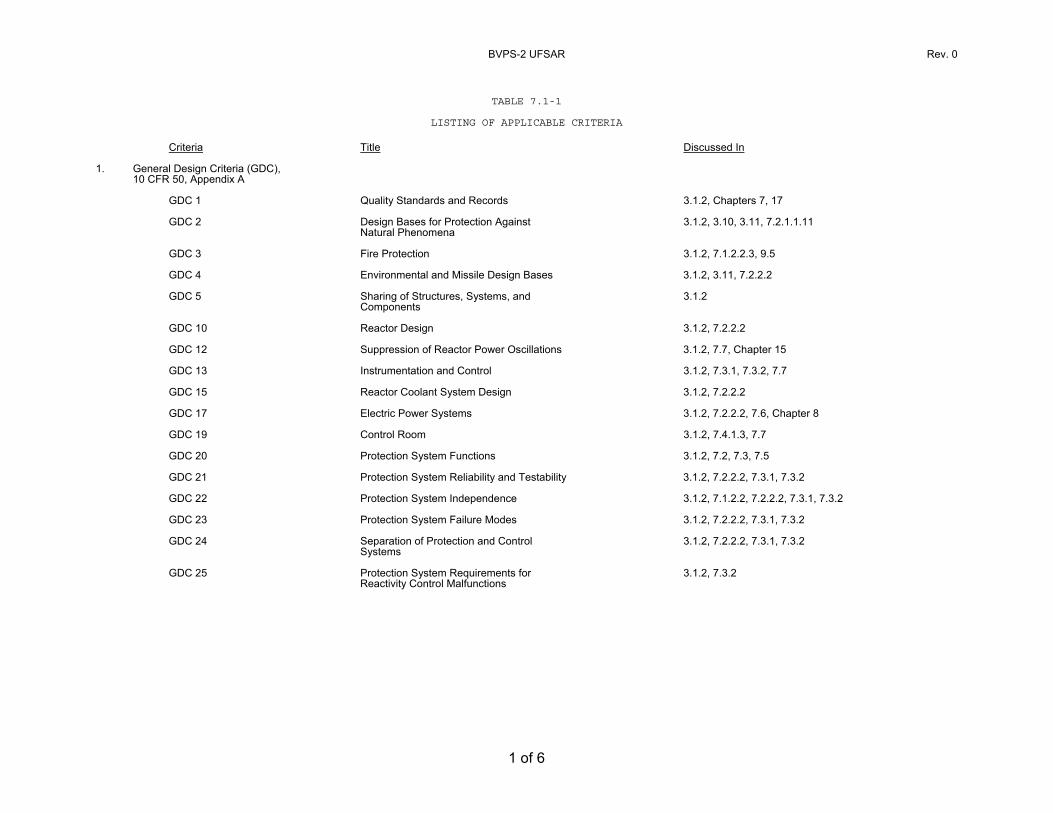
TABLE 7.1-1
LISTING OF APPLICABLE CRITERIA Criteria Title Discussed In
1. General Design Criteria (GDC),
10 CFR 50, Appendix A
GDC 1 Quality Standards and Records 3.1.2, Chapters 7, 17
GDC 2 Design Bases for Protection Against Natural Phenomena
3.1.2, 3.10, 3.11, 7.2.1.1.11
GDC 3 Fire Protection 3.1.2, 7.1.2.2.3, 9.5
GDC 4 Environmental and Missile Design Bases 3.1.2, 3.11, 7.2.2.2
GDC 5 Sharing of Structures, Systems, and Components
3.1.2
GDC 10 Reactor Design 3.1.2, 7.2.2.2
GDC 12 Suppression of Reactor Power Oscillations 3.1.2, 7.7, Chapter 15
GDC 13 Instrumentation and Control 3.1.2, 7.3.1, 7.3.2, 7.7
GDC 15 Reactor Coolant System Design 3.1.2, 7.2.2.2
GDC 17 Electric Power Systems 3.1.2, 7.2.2.2, 7.6, Chapter 8
GDC 19 Control Room 3.1.2, 7.4.1.3, 7.7
GDC 20 Protection System Functions 3.1.2, 7.2, 7.3, 7.5
GDC 21 Protection System Reliability and Testability 3.1.2, 7.2.2.2, 7.3.1, 7.3.2
GDC 22 Protection System Independence 3.1.2, 7.1.2.2, 7.2.2.2, 7.3.1, 7.3.2
GDC 23 Protection System Failure Modes 3.1.2, 7.2.2.2, 7.3.1, 7.3.2
GDC 24 Separation of Protection and Control Systems
3.1.2, 7.2.2.2, 7.3.1, 7.3.2
GDC 25 Protection System Requirements for Reactivity Control Malfunctions
3.1.2, 7.3.2
BVPS-2 UFSAR Rev. 0
2 of 6
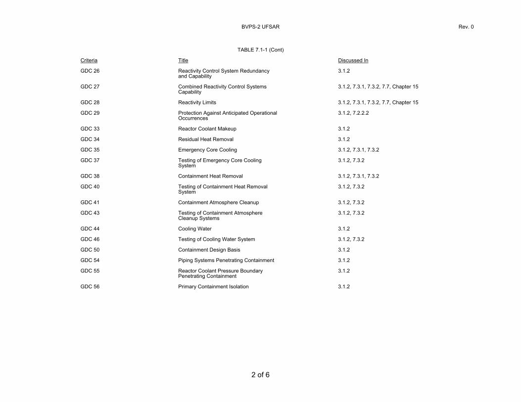
TABLE 7.1-1 (Cont) Criteria Title Discussed In
GDC 26
Reactivity Control System Redundancy and Capability
3.1.2
GDC 27 Combined Reactivity Control Systems Capability
3.1.2, 7.3.1, 7.3.2, 7.7, Chapter 15
GDC 28 Reactivity Limits 3.1.2, 7.3.1, 7.3.2, 7.7, Chapter 15
GDC 29 Protection Against Anticipated Operational Occurrences
3.1.2, 7.2.2.2
GDC 33 Reactor Coolant Makeup 3.1.2
GDC 34 Residual Heat Removal 3.1.2
GDC 35 Emergency Core Cooling 3.1.2, 7.3.1, 7.3.2
GDC 37 Testing of Emergency Core Cooling System
3.1.2, 7.3.2
GDC 38 Containment Heat Removal 3.1.2, 7.3.1, 7.3.2
GDC 40 Testing of Containment Heat Removal System
3.1.2, 7.3.2
GDC 41 Containment Atmosphere Cleanup 3.1.2, 7.3.2
GDC 43 Testing of Containment Atmosphere Cleanup Systems
3.1.2, 7.3.2
GDC 44 Cooling Water 3.1.2
GDC 46 Testing of Cooling Water System 3.1.2, 7.3.2
GDC 50 Containment Design Basis 3.1.2
GDC 54 Piping Systems Penetrating Containment 3.1.2
GDC 55 Reactor Coolant Pressure Boundary Penetrating Containment
3.1.2
GDC 56 Primary Containment Isolation 3.1.2
BVPS-2 UFSAR Rev. 0
3 of 6
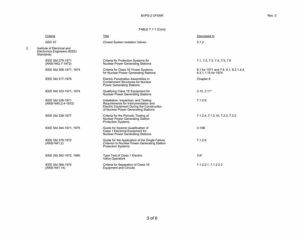
TABLE 7.1-1 (Cont)
Criteria Title Discussed In
GDC 57
Closed System Isolation Valves
3.1.2
2. Institute of Electrical and Electronics Engineers (IEEE) Standards:
IEEE Std 279-1971 (ANSI N42.7-1972)
Criteria for Protection Systems for Nuclear Power Generating Stations
7.1, 7.2, 7.3, 7.4, 7.5, 7.6
IEEE Std 308-1971, 1974 Criteria for Class 1E Power Systems for Nuclear Power Generating Stations
8.1 for 1971 and 7.6, 8.1, 8.2.1.4.4, 8.3.1.1.15 for 1974
IEEE Std 317-1976 Electric Penetration Assemblies in Containment Structures for Nuclear Power Generating Stations
Chapter 8
IEEE Std 323-1971, 1974 Qualifying Class 1E Equipment for Nuclear Power Generating Stations
3.10, 3.11*
IEEE Std 336-1971 (ANSI N45.2.4-1972)
Installation, Inspection, and Testing Requirements for Instrumentation and Electric Equipment During the Construction of Nuclear Power Generating Stations
7.1.2.9
IEEE Std 338-1977 Criteria for the Periodic Testing of Nuclear Power Generating Station Protection Systems
7.1.2.4, 7.1.2.10, 7.2.2, 7.3.2
IEEE Std 344-1971, 1975 Guide for Seismic Qualification of Class 1 Electrical Equipment for Nuclear Power Generating Stations
3.10B
IEEE Std 379-1972 (ANSI N41.2)
Guide for the Application of the Single Failure Criterion to Nuclear Power Generating Station Protection Systems
7.1.2.6
IEEE Std 382-1972, 1980 Type Test of Class 1 Electric Valve Operators
3.9*
IEEE Std 384-1974 (ANSI N41.14)
Criteria for Separation of Class 1E Equipment and Circuits
7.1.2.2.1, 7.1.2.2.2
BVPS-2 UFSAR Rev. 0
4 of 6
TABLE 7.1-1 (Cont)
Criteria Title Discussed In
IEEE Std 334-1974
Standard for Type Tests of Continuous Duty Class Motors Installed Inside the Containment of Nuclear Generating Stations
8.1, 8.3.1
3. Regulatory Guides (RG)
RG 1.6 Independence Between Redundant Standby (Onsite) Power Sources and Between Their Distribution Systems
1.8, 7.6, Chapter 8
RG 1.11 Instrument Lines Penetrating Primary Reactor Containment
1.8, 6.2.4, 7.3.1.1.2
RG 1.22 Periodic Testing of Protection System Actuation Functions
1.8, 7.1.2.4, 7.2.2.2.3, 7.3.2.2.5, 8.3.1, 8.3.2
RG 1.29 Seismic Design Classification
1.8, 3.2.1
RG 1.30 Quality Assurance Requirements for the Installation, Inspections, and Testing of Instrumentation and Electric Equipment
1.8, 8.3.1, 8.3.2, Chapter 17
RG 1.32 Criteria for Safety-Related Electric Power Systems for Nuclear Power Plants
1.8, 7.5, 7.6, 8.2, 8.3.1, 8.3.2
RG 1.47 Bypassed and Inoperable Status Indication for Nuclear Power Plant Safety Systems
1.8, 7.1.2.5, 7.5, 8.2, 8.3
RG 1.53 Application of the Single-Failure Criterion to Nuclear Power Plant Protection Systems
1.8, 3.1.1, 7.1.2.6, 15.0.8
RG 1.62 Manual Initiation of Protective Actions
1.8, 7.2.2.2.3, 7.3.2.2.7
RG 1.63 Electric Penetration Assemblies in Containment Structures for Light- Water-Cooled Nuclear Power Plants
1.8, 8.3
RG 1.68 Initial Test Programs for Water- Cooled Nuclear Power Plants
1.8, Chapter 14
BVPS-2 UFSAR Rev. 0
5 of 6
TABLE 7.1-1 (Cont)
Criteria Title Discussed In
RG 1.70
Standard Format and Content of Safety Analysis Reports for Nuclear Power Plants
1.8, Chapter 7
RG 1.73
Qualification Tests of Electric Valve Operators Installed Inside the Containment of Nuclear Power Plants
1.7, 1.8
RG 1.75 Physical Independence of Electric Systems
1.8, 7.1.2.2.1, 7.1.2.2.2, 8.3.1, 8.3.2
RG 1.89 Qualification of Class 1E Equipment for Nuclear Power Plants
1.8, 8.3.1, 8.3.2
RG 1.97 Instrumentation for Light-Water-Cooled Nuclear Power Plants to Assess Plant Conditions During and Following an Accident
1.8, 6.2, 7.5, 9.3.2, 11.5, 12.3
RG 1.100 Seismic Qualification of Electric Equipment for Nuclear Power Plants
1.8, 3.10, 8.3.1, 8.3.2
RG 1.105 Instrument Setpoints
1.8, 7.1.2.1.9, 7.5
RG 1.106 Thermal Overload Protection for Electric Motors on Motor-Operated Valves
1.8
RG 1.118 Periodic Testing of Electric Power and Protection Systems
1.8, 8.3
4. Branch Technical Positions (BTP)
BTP ICSB 3 Isolation of Low Pressure Systems from the High Pressure Reactor Coolant System
7.6.2
BTP ICSB 4 Requirements of Motor-Operated Valves in the ECCS Accumulator Lines
7.6.4
BTP ICSB 5 Scram Breaker Test Requirements - Technical Specifications
7.2.2.2.3, Chapter 16
BVPS-2 UFSAR Rev. 0
6 of 6
TABLE 7.1-1 (Cont)
Criteria Title Discussed In
BTP ICSB 9
Definition of Use of Channel Calibration - Technical Specification
Chapter 16
BTP ICSB 12
Protection System Trip Point Changes for Operation with Reactor Coolant Pumps Out of Service
7.2.2.2.1, 4.1.1, Chapter 16
BTP ICSB 13 Design Criteria for Auxiliary Feedwater Systems
7.3.2.3
BTP ICSB 14 Spurious Withdrawals of Single Control Rods in Pressurized Water Reactors
7.7.2.2, 15.4
BTP ICSB 18 (PSB) Application of the Single Failure Criterion to Manually-Controlled Electrically-Operated Valves
Tech Spec. 3/4.5
BTP ICSB 20 Design of Instrumentation and Controls Provided to Accomplish Changeover from Injection to Recirculation Mode
7.6.5, 7A, 6.3
BTP ICSB 21 Guidance for Application of Regulatory Guide 1.47
1.8, 7.1.2.5
BTP ICSB 22 Guidance for Application of Regulatory Guide 1.22
1, 8, 7.1.2.4
BTP ICSB 26 Requirements for Reactor Protection System Anticipatory Trips
7.2.1.1.2
NOTE: *Effective dates based on purchase order dates.
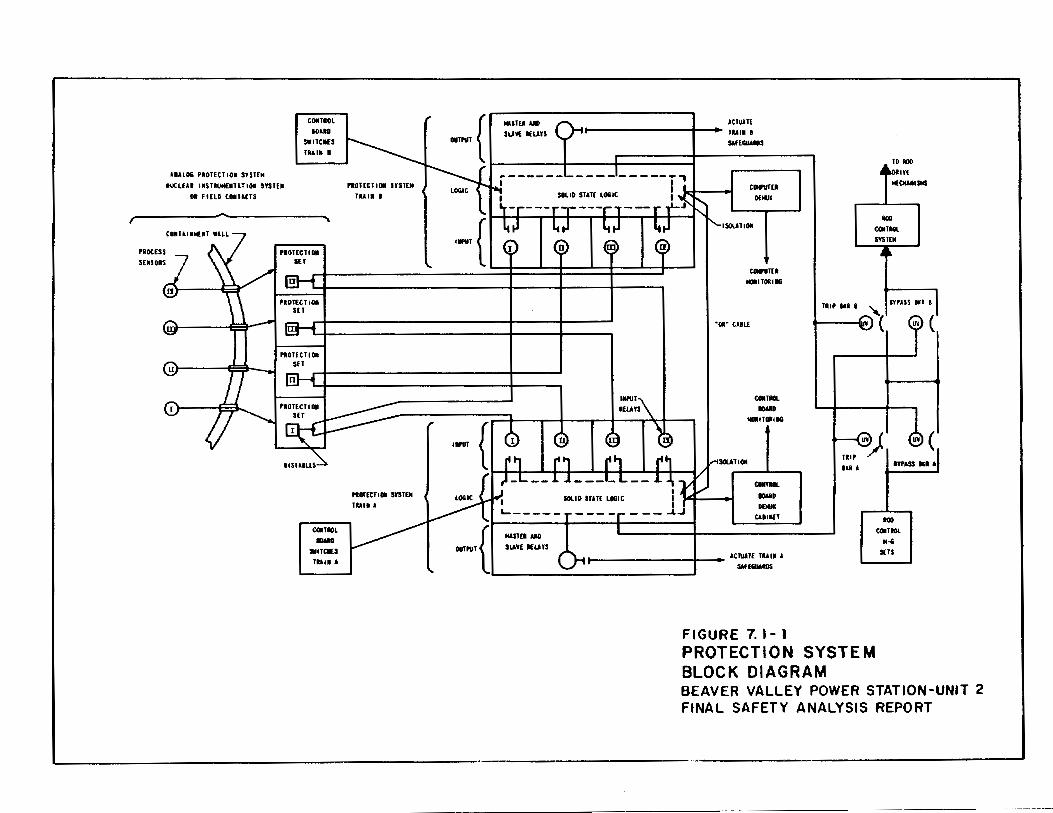
UALOi PIOHCT lOll SYSTEM IWCLUI JISTtiiiiUTUIOI SYITtM
01 F IUD tOIUCTS
CDIITIGL
IGUD
CIIIITIDL IIIMD
•nc.3 lUll A
ICTUATf Hlt---------1--- lUll I
$Af[GIWD$
CIII'I/Ttl Dtllll
ISOUTIDII
COIIrUTU NOIITOIIIMi
"01" CULt
(11111101. IIIMD
NOIITOJIIG
ICUHIIII
COin IIIII. -D DDIII
CUII£1
ACIIIATf TUII A SAftGUliDS
TO 11110
100 COITIOL SYII[N
IYPASS •1 I Tlllf Ill I "
(
U¥ (
!liP ITPASS Ill ~I Ill A
.... (111111101. ~
SETS
FIGURE 7. 1- 1 PROTECTION SYSTEM BLOCK DIAGRAM BEAVER VALLEY POWER STATION-UNIT 2 FINAL SAFETY ANALYSIS REPORT
BVPS-2 UFSAR Rev. 0
7.2-1
7.2 REACTOR TRIP SYSTEM 7.2.1 Description 7.2.1.1 System Description The reactor trip system (RTS) automatically prevents operation of the reactor in an unsafe region by shutting down the reactor whenever the limits of the safe region are approached. The safe operating region is defined by several considerations, such as mechanical/hydraulic limitations on equipment and heat transfer phenomena. Therefore, the RTS maintains surveillance on process variables which are directly related to equipment mechanical limitations such as pressure, pressurizer water level (to prevent water discharge through safety valves), and also on variables which directly affect the heat transfer capability of the reactor (that is, flow and reactor coolant temperatures). Still other parameters utilized in the RTS are calculated from various process variables. In any event, whenever a direct process or calculated variable exceeds a set point, the reactor will be shut down in order to protect against either gross damage to fuel clad or loss of system integrity which could lead to release of radioactive fission products into the containment. The following systems make up the RTS (Reid (1973); Lipchak (1974); and Katz (1971) provide additional background information on the systems):
1. Process instrumentation and control system,
2. Nuclear instrumentation system,
3. Solid state logic protection system,
4. Reactor trip switchgear, and
5. Manual actuation circuit. The RTS consists of sensors which, when connected with analog circuitry consisting of two to four redundant channels, monitor various plant parameters, and digital circuitry, consisting of two redundant logic trains, which receives inputs from the analog protection channels to complete the logic necessary to automatically open the reactor trip breakers. Each of the two trains, Trains A and B, is capable of opening a separate and independent reactor trip breaker, RTA and RTB, respectively. The two trip breakers in series connect three-phase ac power from the rod drive motor-generator sets to the rod drive power cabinets, as shown on Figure 7.2-1, Sheet 2. During Beaver Valley Power Station - Unit 2 (BVPS-2) power operation, a dc undervoltage coil on each reactor trip breaker holds a trip plunger out against its spring, allowing the power to be available at the rod control
BVPS-2 UFSAR Rev. 0
7.2-2
power supply cabinets. For reactor trip, a loss of dc voltage to the undervoltage coil, as well as energization of the shunt trip coil, open the breaker. When either of the trip breakers opens, power is interrupted to the rod drive power supply and the control rods fall, by gravity, into the core. The rods cannot be withdrawn until the trip breakers are manually reset. The trip breakers cannot be reset until the abnormal condition which initiated the trip is corrected. Bypass breakers BYA and BYB are provided to permit testing of the trip breakers. 7.2.1.1.1 Functional Performance Requirements The RTS automatically initiates reactor trip:
1. Whenever necessary to prevent fuel rod damage for an anticipated operational transient (American Nuclear Society (ANS) Condition II),
2. To limit core damage for infrequent faults (ANS Condition
III), and
3. So that the energy generated in the core is compatible with the design provisions to protect the reactor coolant pressure boundary (RCPB) for limiting fault conditions (ANS Condition IV).
The RTS initiates a turbine trip signal whenever a reactor trip is initiated. This prevents the reactivity insertion that would otherwise result from excessive reactor system cooldown and thus avoids unnecessary actuation of the engineered safety features actuation system (ESFAS). The RTS provides for manual initiation of reactor trip by operator action in the main control room. 7.2.1.1.2 Reactor Trips The various reactor trip circuits automatically open the reactor trip breakers whenever a condition monitored by the RTS reaches a preset level. To ensure a reliable system, high quality design, components, manufacturing, quality control, and testing are used. In addition to redundant channels and trains, the design approach provides a RTS which monitors numerous system variables, therefore providing protection system functional diversity. The extent of this diversity has been evaluated for a wide variety of postulated accidents. Table 7.2-1 provides a list of reactor trips, which are described as follows: Nuclear Overpower Trips The specific trip functions generated are as follows:
BVPS-2 UFSAR Rev. 16
7.2-3
1. Power range high neutron flux trip
The power range high neutron flux trip circuit trips the reactor when two out of four power range channels exceed the trip set point. There are two bistable amplifiers for overpower protection in each of four redundant nuclear instrumentation power range channels. Each has its own trip setting. The bistable trip setting (high setting), associated with monitoring the high end of the power range, provides overpower protection and is never blocked. The bistable trip setting (low setting), which provides a more restrictive protection limit during start-up and operation at low power level, can be manually blocked by the operator when two out of four power range channels indicate approximately 10 percent power (P-10). Three out of four channels below 10 percent automatically reinstates the trip (low setting) function. Table 7.2-2 provides a listing of all protection system interlocks and blocks.
2. Intermediate range high neutron flux trip
The intermediate range high neutron flux trip circuit trips
the reactor when one out of two intermediate range channels exceeds the trip set point. This trip, which provides protection during reactor start-up, can be manually blocked if two out of four power range channels are above approximately P-10. Three out of four power range channels below this value automatically reinstate the intermediate range high neutron flux trip. The intermediate range channels (including detectors) are separate from the power range channels. The intermediate range channels can be individually bypassed at the nuclear instrumentation racks to permit channel testing during BVPS-2 shutdown or prior to start-up. This bypass action is annunciated on the main control board.
3. Source range high neutron flux trip
The source range high neutron flux trip circuit trips the
reactor when one of the two source range channels exceeds the trip set point. This trip, which provides protection during reactor start-up and BVPS-2 shutdown, can be manually bypassed when one out of two intermediate range channels reads above the P-6 set point value and is automatically reinstated when both intermediate range channels decrease below the P-6 set point value. This trip is also automatically bypassed by two out of four logic from the power range protection interlock (P-10). This trip function can also be reinstated below P-10 by an administrative action requiring manual actuation of two control board-mounted switches. Each switch will reinstate the trip function in one of the two protection logic trains. The source range
BVPS-2 UFSAR Rev. 17
7.2-4
trip point is set between the P-6 set point (source range cutoff power) and the maximum source range power. The channels can be individually bypassed at the nuclear instrumentation racks to permit channel testing during BVPS-2 shutdown or prior to start-up. This bypass action is annunciated on the main control board.
4. Power range high positive neutron flux rate trip
This circuit trips the reactor when an abnormal rate of
increase in nuclear power occurs in two out of four power range channels. This trip provides departure from nucleate boiling (DNB) protection against rod ejection accidents of low worth from mid-power and is always active.
Core Thermal Overpower Trips The specific trip functions generated are as follows:
1. Overtemperature ΔT trip
This trip protects the core against low DNBR and trips the reactor on coincidence, as listed in Table 7.2-1, with one set of temperature measurements per loop. The set point for this trip is continuously calculated by analog circuitry for each loop by solving the equation found in Technical Specification Table 3.3.1-1.
BVPS-2 UFSAR Rev. 16
7.2-5
A separate ion chamber unit supplies the flux signal for each
overtemperature ΔT trip channel. Increases in Δφ beyond a predefined deadband will result in a decrease in trip set point (Figures 7.2-2 and 7.2-3). The required one pressurizer pressure parameter per loop is obtained from separate sensors connected to three pressure taps at the top of the pressurizer. Section 7.2.2.3.3 provides an analysis of this arrangement. Figure 7.2-1, Sheet 5, shows the logic for overtemperature ΔT trip function.
2. Overpower ΔT trip
This trip protects against excessive power (fuel rod rating
protection) and trips the reactor on coincidence, as listed in Table 7.2-1, with one set of temperature measurements per loop. Table 7.2-4 describes other events for which the overpower ΔT trip may provide a backup or secondary trip function.
BVPS-2 UFSAR Rev. 17
7.2-6
The set point for each channel is continuously calculated, using the equation found in Technical Specification Table 3.3.1-1.
The source of temperature information is identical to that of the
overtemperature ΔT trip, and the resultant ΔT set point is compared to the same ΔT. Figure 7.2-1, Sheet 5, shows the logic for this trip function.
Reactor Coolant System Pressurizer Pressure Trips The specific trip functions generated are as follows:
1. Pressurizer low pressure trip
The purpose of this trip is to protect against low pressure which could lead to DNB. The parameter being sensed is reactor coolant pressure, as measured in the pressurizer. Above P-7, the reactor is tripped when the pressurizer pressure measurements fall below preset limits. This signal is compensated to account for the fact that the measurement is in the pressurizer rather than in the core proper. This trip is blocked below P-7 to permit start-up. The trip logic and interlocks are given in Table 7.2-1, and the trip logic is shown on Figure 7.2-1, Sheet 6.
The reactor trips comply with the intent of NUREG-0737 (USNRC
1980), TMI Action Item II.K.1.17.
BVPS-2 UFSAR Rev. 13
7.2-7
2. Pressurizer high pressure trip
The purpose of this trip is to protect the reactor coolant
system (RCS) against system overpressure and to prevent opening of the pressurizer safety valves. The same sensors and transmitters used for the pressurizer low pressure trip are used for the high pressure trip except that separate bistables are used for trip. These bistables trip when uncompensated pressurizer pressure signals exceed preset limits on coincidence, as listed in Table 7.2-1. There are no interlocks or permissives associated with this trip function. This trip protects against overstressing the RCPB. The logic for this trip is shown on Figure 7.2-1, Sheet 6.
3. Pressurizer high water level trip
This trip is provided as a backup to the high pressurizer
pressure trip and serves to prevent water relief through the pressurizer safety valves, and therefore provides for equipment protection. This trip is blocked below P-7 to permit start-up. The trip logic for this function is shown on Figure 7.2-1, Sheet 6.
Reactor Coolant System Low Flow Trips These trips protect the core from DNB in the event of a loss-of-coolant flow (LOCF) situation. Figure 7.2-1, Sheet 5 shows the logic for these trips. The means of sensing the LOCF are as follows:
1. Low reactor coolant flow
The parameter sensed is reactor coolant flow. Three differential pressure transmitters in each coolant loop are used to provide the status of reactor coolant flow. The basic function of this device is to provide information as to whether or not a reduction in flow has occurred. An output signal from two out of the three bistables in a loop would indicate a low flow in that loop. Above P-7, two out of three loop low flow indications will trip the reactor. Above P-8, low flow in any one loop will cause a reactor trip. The coincidence logic and interlocks are given in Table 7.2-1. Trip logic for this function is shown on Figure 7.2-1, Sheet 5.
BVPS-2 UFSAR Rev. 16
7.2-8
2. Reactor coolant pump breaker trip
One open breaker signal is generated for each reactor coolant pump (RCP). Above the P-7 set point, the reactor trips on two open breaker signals. One set of auxiliary contacts on each pump breaker serves as the input signal to the trip logic. The coincident logic and interlocks are given in Table 7.2-1. The trip logic for this function is shown on Figure 7.2-1, Sheet 5.
3. Reactor coolant pump bus undervoltage trip
This trip is anticipatory to the low reactor coolant flow
trip to protect against low flow which can result from loss of voltage to more than one RCP motor (for example, loss of offsite power or RCP breakers opening). There is one undervoltage sensing relay connected to each phase of each RCP bus. These relays provide an output signal when the bus voltage goes below approximately 70 percent of rated voltage. Signals from these relays are delayed to prevent spurious trips caused by short term voltage perturbations. The coincidence logic and interlocks are given in Table 7.2-1.
4. Reactor coolant pump bus underfrequency trip
This trip is anticipatory to the low reactor coolant flow
trip to protect against low flow resulting from pump underfrequency, for example, a major grid frequency disturbance. The function of this trip is to trip the reactor for an underfrequency condition. There is one underfrequency sensing relay connected to each RCP bus. Signals from relays connected to any two of the buses (time delayed up to approximately 0.5 second to prevent spurious trips caused by short term frequency perturbations) will trip the reactor if power is above P-7. 7.2-1, Sheet 5, shows the logic for the RCP underfrequency trip.
Steam Generator Trips The specific trip functions generated are as follows:
1. Low-low steam generator water level trip
This trip protects the reactor from loss of heat sink. This trip is actuated on two out of three low-low water level signals occurring in any steam generator. The logic is shown on Figure 7.2-1, Sheet 7.
BVPS-2 UFSAR Rev. 7
7.2-9
Reactor Trip On a Turbine Trip (Anticipatory) The reactor trip on a turbine trip is actuated by two out of three logic from low emergency trip fluid signals or by all closed signals from the turbine main stop valves. A turbine trip causes a direct reactor trip above P-9. The reactor trip on turbine trip provides additional protection and conservatism beyond that required. This trip is included as part of good engineering practice and prudent design. No credit is taken in any of the safety analyses (Chapter 15) for this trip. The turbine provides anticipatory trips to the reactor protection system (RPS) from contacts which change state when the turbine main stop valves close or when the turbine emergency trip fluid pressure goes below its set point. The anticipatory trips comply with the intent of NUREG-0737 (USNRC 1980), TMI Action Items II.K.3.10 and II.K.3.12. One of the design bases considered in the protection system is the possibility of an earthquake. With respect to these contacts, their functioning is unrelated to a seismic event in that they are anticipatory to other diverse parameters which cause reactor trip. The contacts are shut during BVPS-2 operation and open to cause reactor trip when the turbine is tripped. No power is provided to the protection system from the contacts; they merely serve to interrupt power to cause reactor trip. This design functions in a de-energize-to-trip fashion to cause a plant trip if power is interrupted in the trip circuitry. This ensures that the protection system will in no way be degraded by this anticipatory trip because seismic design considerations do not form part of the design bases for anticipatory trip sensors. (The RPS cabinets which receive the inputs from the anticipatory trip sensors are seismically qualified, as discussed in Section 3.10.) Circuit analysis show that the functional performance of the protection system would not be degraded by credible electrical faults, such as opens and shorts in the circuits associated with reactor trip from turbine trip. The contacts of redundant sensors on the steam stop valves and the trip fluid pressure system are connected through the grounded side of the ac supply circuits in the
BVPS-2 UFSAR Rev. 2B
7.2-10
solid state protection system (SSPS). Loss of signal caused by circuit faults would produce either a partial or full reactor trip. The sensing devices associated with, or mounted on the turbine conform to requirements applicable to the anticipatory trip of the reactor. The anticipatory trips thus meet Institute of Electrical and Electronics Engineers (IEEE) Standard 279-1971 and Branch Technical Position ICSB 26, including redundancy, separation, single failure, etc. Seismic qualification of the contacts sensors is not required. The logic for this type of trip is shown on Figure 7.2-1, Sheet 15. Safety Injection Signal Actuation Trip A reactor trip occurs when safety injection is actuated. The means of actuating safety injection is described in Section 7.3. Figure 7.2-1, Sheet 8, shows the logic for this trip. Manual Trip The manual trip consists of two switches with two outputs on each switch. One output is used to actuate the Train A trip breaker, the other output actuates the Train B trip breaker. Operating a manual trip switch removes the voltage from the undervoltage coil and energizes the shut trip coils in the breakers. There are no interlocks which can block this trip. Figure 7.2-1, Sheet 3, shows the manual trip logic. 7.2.1.1.3 Reactor Trip System Interlocks Power Escalation Permissives The overpower protection provided by the out-of-core nuclear instrumentation consists of three discrete, but overlapping, ranges. Continuation of start-up operation or power increase requires a permissive signal from the higher range instrumentation channels before the lower range trips can be manually blocked by the operator. One of two intermediate range permissive signals (P-6) is required prior to source range trip blocking. A source range manual block is provided for each logic train and the blocks must be in effect on both trains in order to continue power escalation. Source range trips are automatically reactivated when both intermediate range channels are below the permissive (P-6) set point. There are two manual reset switches for administratively reactivating the source range trip and detector high voltage when between permissives P-6 and P-l0, if required. Source range trip block and high voltage cutoff are always maintained when power is above the permissive P-10 set point with high voltage manual control switch in the normal position. If the high voltage manual control switch, located on the source range drawer, is in the on or off position, it overrides any automatic actions. The intermediate range trip and power range (low set point) trip can only be blocked after satisfactory operation and permissive
BVPS-2 UFSAR Rev. 16
7.2-11
information are obtained from two of four power range channels. Individual blocking switches are provided so that the low range power range trip and intermediate range trip can be independently blocked (one switch for each train for a total of four switches). These trips are automatically reactivated when any three out of the four power range channels are below the permissive (P-10) set point, thus ensuring automatic activation to more restrictive trip protection. The development of permissives P-6 and P-10 is shown on Figure 7.2-1, Sheet 4. All of the permissives are digital, and they are derived from analog signals in the nuclear power range and intermediate range channels. Table 7.2-2 provides the list of protection system interlocks. Block of Reactor Trips at Low Power Interlock P-7 blocks a reactor trip (below approximately 10 percent of full power) on a low reactor coolant flow in more than one loop, two or more RCP breakers open, RCP undervoltage, RCP underfrequency, pressurizer low pressure, or pressurizer high water level. Figure 7.2-1, Sheets 5 and 6, illustrate permissive applications. The low power signal (P-7) is derived from three out of four power range neutron flux signals below the set point in coincidence with two out of two turbine first stage pressure signals below the set point (low plant load). The permissive logic is shown on 7.2-1, Sheet 4. The P-8 interlock blocks a reactor trip when the plant is below approximately 30 percent of full power, on a low reactor coolant flow in any one loop. The block action (absence of the P-8 interlock signal) occurs when three out of four neutron flux power range signals are below the set point. Thus, below the P-8 set point, an automatic reactor trip will not occur until two loops are indicating low flow. Figure 7.2-1, Sheet 4, shows derivation of P-8, and Sheet 5, for its function in the low flow reactor trip logic. The P-9 interlock blocks reactor trip on a turbine trip when the plant is below approximately 49 percent of full power. The block action (absence of the P-9 interlock signal) occurs when three out of four neutron flux power range signals are below the set point. Thus, below the P-9 set point, the reactor will be allowed to operate if the turbine has tripped. Figure 7.2-1, Sheet 4, depicts derivation of P-9, and Sheet 15 shows applicable logic. The list of protection system blocks is given in Table 7.2-2.
BVPS-2 UFSAR Rev. 12
7.2-12
7.2.1.1.4 Coolant Temperature Sensor Arrangement The hot and cold leg temperature signals required for input to the protection and control functions are obtained using thermowell mounted RTDs installed in each reactor coolant loop. The hot leg temperature measurement in each loop is accomplished using three fast response narrow range RTDs mounted in thermowells. Two of the three thermowells in each loop are located within the scoops previously used to supply temperature samples to the RTD bypass manifold. The third RTD could not be located within the scoop due to structural interferences and is located upstream from the scoop plane. The two scoops used to accommodate the thermowells were modified by machining a flow hole in the end of the scoop to facilitate the flow of water through the existing holes in the leading edge of the scoop and passed the temperature sensitive tip of the RTD. Due to temperature streaming the temperatures measured by the three hot leg RTDs are different and therefore these signals are electronically averaged to generate a hot leg average temperature. Provisions were made in the RTD electronics to allow for operation with only two RTDs in service. The two RTD measurement can be biased to correct for the difference compared with the three RTD average. The cold leg temperature measurement in each loop is accomplished by one fast response, narrow range, dual element RTD. The original cold leg RTD bypass penetration nozzle was modified to accept the thermowell. Signals from these instruments are used to compute the reactor coolant ΔT (temperature of the hot leg, Thot, minus the temperature at the cold leg, Tcold,) and an average reactor coolant temperature (Tavg). The
Tavg for each loop is indicated on the main control board. Wide Range Cold Leg and Hot Leg Temperatures Wide Range temperature detectors, located in the thermometer wells in the cold and hot leg piping of each loop, supply signals to wide range temperature recorders. This information is used by the operator to control coolant temperature during start-up and shutdown.
BVPS-2 UFSAR Rev. 0
7.2-13
7.2.1.1.5 Pressurizer Water Level Reference Leg Arrangement The design of the pressurizer water level instrumentation includes a tank level arrangement using differential pressure between an upper and lower tap. 7.2.1.1.6 Analog System The analog system consists of two instrumentation systems: the process instrumentation system and the nuclear instrumentation system (NIS). Process instrumentation includes those devices (and their interconnection into systems) which measure temperature, pressure, fluid flow, and fluid level as in tanks or vessels. Process instrumentation specifically excludes nuclear and radiation measurements. The process instrumentation includes the process measuring devices, power supplies, indicators, recorders, alarm actuating devices, controllers, signal conditioning devices, etc, which are necessary for day-to-day operation of the nuclear steam supply system as well as for monitoring BVPS-2, and providing initiation of protective functions upon approach to unsafe plant conditions. The primary function of nuclear instrumentation is to protect the reactor by monitoring the neutron flux and generating appropriate trips and alarms for various phases of reactor operating and shutdown conditions. It also provides a secondary control function and indicates reactor status during start-up and power operation. The NIS uses information from these separate types of instrumentation channels to provide three discrete protection levels. Each range of instrumentation (source, intermediate, and power) provides the necessary overpower reactor trip protection required during operation in that range. The overlap of instrument ranges provides reliable continuous protection, beginning with source level through the intermediate and low power level. As the reactor power increases, the overpower protection level is increased by administrative procedures after satisfactory higher range instrumentation operation is obtained. Automatic reset to more restrictive trip protection is provided when reducing power. Various types of neutron detectors, with appropriate solid state electronic circuitry, are used to monitor the leakage neutron flux from a completely shutdown condition to 120 percent of full power. The neutron flux covers a wide range between these extremes. Therefore, monitoring with several ranges of instrumentation is necessary. The lowest range (source range) covers six decades of leakage neutron flux. The lowest observed count rate depends on the strength of the neutron sources in the core and the core multiplication associated with the shutdown reactivity. This is generally greater than two
BVPS-2 UFSAR Rev. 11
7.2-14
counts per second. The next range (intermediate range) covers eight decades. Detectors and instrumentation are chosen to provide overlap between the higher portion of the source range and the lower portion of the intermediate range. The highest range of instrumentation (power range) covers approximately two decades of the total instrumentation range. This is a linear range that overlaps with the higher portion of the intermediate range. The system previously described provides main control room indication and recording of signals proportional to reactor neutron flux during core loading, shutdown, start-up, and power operation, as well as during subsequent refueling. Start-up rate indication for the source and intermediate range channels is provided at the main control board. Reactor trip, rod stop, control and alarm signals are transmitted to the reactor control and protection system for automatic plant control. Equipment failures and test status information are annunciated in the main control room. Reid (1973) and Lipchak (1974) provide additional background information on the process and nuclear instrumentation. 7.2.1.1.7 Solid State Protection System The SSPS takes binary inputs (voltage/no voltage) from the process and nuclear instrument channels corresponding to conditions (normal/abnormal) of BVPS-2 parameters. The system combines these signals in the required logic combination and generates a trip signal simultaneously to the shunt trip coils and to the undervoltage trip attachment and shunt trip auxiliary relay coils of the reactor trip circuit breakers when the necessary combination of signals occur. The system also provides annunciator, status light, and computer input signals which indicate the condition of bistable input signals, partial trip, and full trip functions and the status of the various blocking, permissive, and actuation functions. In addition the system includes means for semi-automatic testing of the logic circuits. 7.2.1.1.8 Isolation Amplifiers In certain applications, it is advantageous to employ control signals derived from individual protection channels through isolation amplifiers contained in the protection channel, as permitted by IEEE Standard 279-1971. In all of these cases, except as stated below, analog signals derived from protection channels for nonprotective functions are obtained through isolation amplifiers located in the analog protection racks. By definition, nonprotective functions include those signals used for control, remote process indication, and computer monitoring. Steam flow and feedwater flow no longer have protective functions since the low feedwater trip was eliminated, but portions of these loops are still protection grade due to their association with the protection racks and color coded signal cable routing. Additional informationand discussions can be found in Section 7.1.2.2.1.
BVPS-2 UFSAR Rev. 0
7.2-15
7.2.1.1.9 Energy Supply and Environmental Variations The energy supply for the RTS, including the voltage and frequency variations, is described in Section 7.6 and Chapter 8. The environmental variations, throughout which the system will perform, are given in Section 3.11 and Chapter 8. 7.2.1.1.10 Set Points The set points that require trip action are given in Chapter 16. Further discussion on set points is found in Section 7.1.2.1.9. 7.2.1.1.11 Seismic Design The seismic design considerations for the RTS are given in Section 3.10. This design meets the requirements of General Design Criterion (GDC) 2. 7.2.1.2 Design Bases Information The following information presents the design bases information requested by Section 3 of IEEE Standard 279-1971. Functional logic diagrams are presented on Figure 7.2-1. 7.2.1.2.1 Generating Station Conditions The following are the generating station conditions requiring reactor trip.
1. The DNBR approaching 1.30,
2. Power density (kW/ft) approaching rated value for Condition II faults (Chapter 4 discusses fuel design limits), or
3. The RCS overpressure creating stresses approaching the limits
specified in Chapter 5. 7.2.1.2.2 Generating Station Variables The following are the variables required to be automatically monitored in order to provide reactor trips (Table 7.2-1).
1. Neutron flux,
2. Reactor coolant temperature,
3. Reactor coolant system pressure (pressurizer pressure),
4. Pressurizer water level, 5. Reactor coolant flow,
BVPS-2 UFSAR Rev. 7
7.2-16
6. Reactor coolant pump operational status (bus voltage and frequency, and breaker position),
7. Steam generator water level, and
8. Turbine-generator operational status (trip fluid pressure and
stop valve position). 7.2.1.2.3 Spatially Dependent Variables The following variable is spatially dependent: Reactor coolant temperature: Section 7.3.1.2 discusses this variable's spatial dependence. 7.2.1.2.4 Limits and Margins The parameter values that will require reactor trip are given in Chapter 16, Technical Specifications, and in Chapter 15, Accident Analyses. Chapter 15 demonstrates that the set points used in Chapter 16 are conservative. The set points for the various functions in the RTS have been analytically determined such that the operational limits so prescribed will prevent fuel rod clad damage and loss of integrity of the RCS as a result of any Condition II incident (anticipated malfunction). As such, during any Condition II incident, the RTS limits the following parameters to:
1. Minimum DNBR = 1.3,
2. Maximum system pressure = 2,750 psia, and
3. Fuel rod maximum linear power = 15.2 kW/ft. The accident analyses described in Chapter 15 demonstrate that the functional requirements as specified for the RTS are adequate to meet the preceding considerations, even assuming, for conservatism, adverse combinations of instrument errors. A discussion of the safety limits associated with the reactor core and RCS, plus the limiting safety system set points, are presented in the Technical Specifications. 7.2.1.2.5 Abnormal Events The following malfunctions, accidents, or other unusual events which could physically damage RTS components or could cause environmental changes are considered in design:
1. Earthquakes (Chapters 2 and 3),
BVPS-2 UFSAR Rev. 17
7.2-17
2. Fire (Section 9.5),
3. Explosion (hydrogen buildup inside containment, Section 6.2.5),
4. Missiles (Section 3.5),
5. Flood (Chapters 2 and 3), and
6. Wind and tornadoes (Section 3.3).
The RTS fulfills the requirements of IEEE Standard 279-1971 to provide automatic protection and to provide initiating signals to mitigate the consequences of faulted conditions. The RTS includes provisions to provide protection against destruction of the system from fires, explosions, flood, wind, and tornadoes (refer to items 1 through 6). The discussions in Section 7.1.2.1.7 and this section adequately address or reference the coverage of the effects of abnormal events on the RTS in conformance with the applicable GDC. 7.2.1.2.6 Minimum Performance Requirements Reactor Trip System Response Times The RTS response time is defined in Section 7.1. Allowable response times are contained in Licensing Requirements Manual Table 3.3.1-1. Section 7.1.2.7 provides a discussion of periodic response time verification capabilities. Reactor Trip Accuracies Accuracy is defined in Section 7.1. Reactor trip accuracies are tabulated in Table 7.2-3. The trip set point is determined by factors other than the most accurate portion of the instrument’s range. The safety limit set point is determined only by the accident analysis. As described previously, allowance is then made for process uncertainties, instrument error, instrument drift, and calibration uncertainty to obtain the nominal set point value, which is actually set into the equipment. The only requirement on the instrument’s accuracy value is that over the instrument span, the error must always be less than or equal to the error value allowed in the accident analysis. The instrument does not need to be the most accurate at the set point value as long as it meets the minimum accuracy requirement. The accident analysis accounts for the expected errors at the actual set point.
BVPS-2 UFSAR Rev. 13
7.2-18
Protection System Ranges Typical protection system ranges are tabulated in Table 7.2-3. Range selection for the instrumentation covers the expected range of the process variable being monitored during power operation. Limiting set points are at least 5 percent from the end of the instrument span. 7.2.2 Analyses 7.2.2.1 Failure Modes and Effects Analyses A failure modes and effects analysis of the RTS has been performed. Results of this fault tree analysis are presented by Gangloff (1971). 7.2.2.2 Evaluation of Design Limits While most set points used in the RTS are fixed, there are variable set points, most notably the overtemperature ΔT and overpower ΔT set points. All set points in the RTS have been selected on the basis of engineering design or safety studies. The capability of the RTS to prevent loss of integrity of the fuel clad and/or RCS pressure boundary during Condition II and III transients is demonstrated in Chapter 15. These accident analyses are carried out using those set points determined from results of the engineering design studies. Set point limits are presented in the Technical Specifications. A discussion of the intent for each of the various reactor trips of the accident analyses (where appropriate) which utilizes this trip is presented as follows. It should be noted that the selected trip set points all provide for margin before protection action is actually required to allow for uncertainties and instrument errors. The design meets the requirements of GDC 10 and 20. 7.2.2.2.1 Trip Set Point Discussion It has been pointed out previously that below a DNBR of 1.30 there is likely to be significant local fuel clad failure. The DNBR existing at any point in the core for a given core design can be determined as a function of the core inlet temperature, power output, operating pressure, and flow. Consequently, core safety limits in terms of a DNBR equal to 1.30 for the hot channel can be developed as a function of ΔT, Tavg, and pressure for a specified flow, as illustrated by the solid lines on Figure 7.2-3. Also shown as solid lines on Figure 7.2-3 are the locus of conditions equivalent to 118 percent of power as a function of ΔT and Tavg representing the overpower (kW/ft) limit on the fuel. The dashed lines indicate the maximum permissible set point (ΔT) as a function of Tavg and pressure for the overtemperature and overpower reactor trip. Actual values of set point constants in the equation representing the dashed lines are as given in the Technical Specifications. These values are conservative to allow for instrument errors. The design meets the requirements of GDC 10, 15, 20, and 29.
BVPS-2 UFSAR Rev. 12
7.2-19
The DNBR is not a directly measurable quantity; however, the process variables that determine DNBR are sensed and evaluated. Small isolated changes in various process variables may not individually result in violation of a core safety limit; whereas the combined variations, over sufficient time, may cause the overpower or overtemperature safety limit to be exceeded. The design concept of the RTS accommodates this situation by providing reactor trips associated with individual process variables in addition to the overpower/overtemperature safety limit trips. Process variable trips prevent reactor operation whenever a change in the monitored value is such that a core or system safety limit is in danger of being exceeded should operation continue. Basically, the high pressure, low pressure, and overpressure/overtemperature ΔT trips provide sufficient protection for slow transients, as opposed to such trips as low flow or high flux which will trip the reactor rapidly for changes in flow or flux, respectively, that would result in fuel damage before actuation of the slower responding ΔT trips could be effected.
Therefore, the RTS has been designed to provide protection for fuel cladding and RCS pressure boundary integrity where: 1) a rapid change in a single variable of factor which will result in exceeding a core or a system safety limit, and 2) a slow change in one or more variables will have an integrated effect which will cause safety limits to be exceeded. Overall, the RTS offers diverse and comprehensive protection against fuel clad failure and/or loss of RCS integrity for Condition II and III accidents. Table 7.2-4 lists the various trips of the RTS.
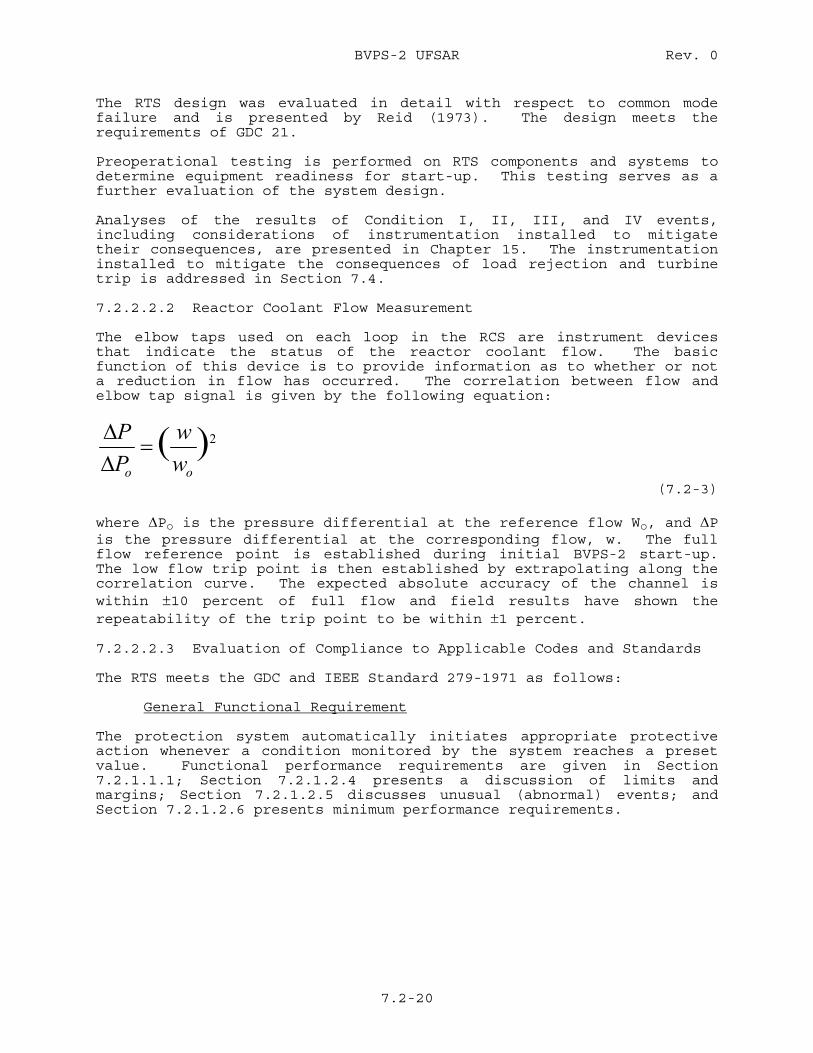
BVPS-2 UFSAR Rev. 0
7.2-20
The RTS design was evaluated in detail with respect to common mode failure and is presented by Reid (1973). The design meets the requirements of GDC 21. Preoperational testing is performed on RTS components and systems to determine equipment readiness for start-up. This testing serves as a further evaluation of the system design. Analyses of the results of Condition I, II, III, and IV events, including considerations of instrumentation installed to mitigate their consequences, are presented in Chapter 15. The instrumentation installed to mitigate the consequences of load rejection and turbine trip is addressed in Section 7.4. 7.2.2.2.2 Reactor Coolant Flow Measurement The elbow taps used on each loop in the RCS are instrument devices that indicate the status of the reactor coolant flow. The basic function of this device is to provide information as to whether or not a reduction in flow has occurred. The correlation between flow and elbow tap signal is given by the following equation:
2)(oo ww
PP=
ΔΔ
(7.2-3) where ΔPo is the pressure differential at the reference flow Wo, and ΔP is the pressure differential at the corresponding flow, w. The full flow reference point is established during initial BVPS-2 start-up. The low flow trip point is then established by extrapolating along the correlation curve. The expected absolute accuracy of the channel is within ±10 percent of full flow and field results have shown the repeatability of the trip point to be within ±1 percent. 7.2.2.2.3 Evaluation of Compliance to Applicable Codes and Standards The RTS meets the GDC and IEEE Standard 279-1971 as follows: General Functional Requirement The protection system automatically initiates appropriate protective action whenever a condition monitored by the system reaches a preset value. Functional performance requirements are given in Section 7.2.1.1.1; Section 7.2.1.2.4 presents a discussion of limits and margins; Section 7.2.1.2.5 discusses unusual (abnormal) events; and Section 7.2.1.2.6 presents minimum performance requirements.
BVPS-2 UFSAR Rev. 10
7.2-21
Single Failure Criterion The protection system is designed to provide two, three, or four instrumentation channels for each protective function and two logic train circuits. These redundant channels and trains are electrically isolated and physically separated. Thus, any single failure within a channel or train will not prevent system protective action at the system level when required. Single failure within the protection system shall not prevent proper protective action at the system level when required. Components and systems not qualified for seismic events or accident environments and nonsafety-grade components and systems are assumed to fail to function if failure adversely affects protection system performance. These components and systems are assumed to function if functioning adversely affects protection system performance. All failures in the protection system that can be predicted as a result of an event for which the protection system is designed to provide a protective function are assumed to occur if the failure adversely affects the protection system performance. After assuming the failures of nonsafety-grade, non-qualified equipment and those failures caused by a specific event, a random single failure is arbitrarily assumed. With these failures assumed, the protection system must be capable of performing the protective functions credited in the accident analyses. Loss of input power, the most likely mode of failure, to a channel or logic train will result (except for containment spray) in a signal calling for protective action. This design meets the requirements of GDC 23. To prevent the occurrence of common mode failures, functional diversity, physical and electrical separation, and testing are employed, as discussed by Gangloff (1971). The design meets the requirements of GDC 21 and 22. Quality of Components and Modules The quality assurance requirements imposed on the components and modules used in the RTS satisfy GDC 1. Equipment Qualification Sections 3.10 and 3.11 discuss the type tests made to verify the performance requirements. The test results demonstrate that the design meets the requirements of GDC 4. Channel Integrity Protection system channels required to operate in accident conditions maintain necessary functional capability under extremes of conditions relating to environment, energy supply, malfunctions, and accidents. Vital power for the RTS is described in Section 7.6 and Chapter 8. The environmental variations throughout which the system will perform is discussed in Section 3.11.
BVPS-2 UFSAR Rev. 10
7.2-22
Independence Channel independence is carried throughout the system, extending from the sensor through to the devices actuating the protective function. Physical separation is used to achieve separation of redundant transmitters. Separation of wiring is achieved using separate wireways, cable trays, conduit runs, and containment penetrations for each redundant channel. Redundant analog equipment is separated by locating modules in different protection cabinets. Each redundant protection channel set is energized from a separate ac power feed. This design meets the requirements of GDC 21. Two reactor trip breakers are actuated by two separate logic matrices which interrupt power to the control rod drive mechanisms (CRDMs). The breaker main contacts are connected in series with the power supply so that opening either breaker interrupts power to all CRDMs, permitting the rods to fall into the core (Figure 7.1-1). The design philosophy is to make maximum use of a wide variety of measurements. The protection system continuously monitors numerous diverse system variables. The extent of this diversity has been evaluated for a wide variety of postulated accidents. Generally, two or more diverse protection functions would terminate an accident before intolerable consequences could occur. This design meets the requirements of GDC 22. Control and Protection System Interaction The protection system is designed to be independent of the control system. In certain applications the control signals and other nonprotective functions are derived from individual protective channels through isolation amplifiers. The isolation amplifiers are classified as part of the protection system and are located in the protection racks. Nonprotective functions include those signals used for control, remote process indication, and computer monitoring. The isolation amplifiers are designed such that a short circuit, open circuit, or the application of credible fault potentials on the isolated output portion of the circuit (that is, the nonprotective side of the circuit) will not affect the input (protective) side of the circuit. The signals obtained through the isolation amplifiers are never returned to the protection racks. In addition to employing isolation between protection and control circuits, control circuit design also prevents adverse protection/control circuit interaction. An example of such a design is the use of the median signal selector in the steam generator water level control circuit. The median signal selector receives the three level measurement signals and transmits the median of these signals for level control purposes. This signal will reject a failed high or low steam generator level measurement and therefore this failure will not affect the system. The control and protection system interaction has been eliminated by the median signal selector design. This design meets the requirements of GDC 24 and Paragraph 4.7 of IEEE Standard 279-1971.
BVPS-2 UFSAR Rev. 10
7.2-22a
The results of applying fault conditions on the output portion of the isolation amplifiers show that no significant disturbance to the isolation amplifier input signal occurred. Section 7.1.2.2.1 provides a discussion of additional tests on the protection system. Derivation of System Inputs To the extent feasible and practical, protection system inputs are derived from signals which are direct measures of the desired variables. Variables monitored for the various reactor trips are listed in Section 7.2.1.2.2. Capability for Sensor Checks The operational availability of each system input sensor during reactor operation is accomplished by cross-checking between channels that bear a known relationship to each other and that have readouts available. Channel checks are discussed in Chapter 16. Capability for Testing The RTS is capable of being tested during power operation. Where only parts of the system are tested at any one time, the testing sequence provides the necessary overlap between the parts to assure
BVPS-2 UFSAR Rev. 12
7.2-23
complete system operation. The testing capabilities are in conformance with Regulatory Guide 1.22, as discussed in Section 7.1.2.4. The protection system is designed to permit periodic testing of the analog channel portion of the RTS during reactor power operation without initiating a protective action. This is because of the coincidence logic required for reactor trip. These tests may be performed at any plant power from cold shutdown to full power. Before starting any of these tests with BVPS-2 at power, all redundant reactor trip channels associated with the function to be tested must be in the normal (untripped) mode and the plant in stable operation in order to avoid spurious trips. Set points are located in the technical specifications. 1. Analog Channel Tests Analog channel testing is performed at the analog instrumentation
cabinet by individually inputting signals into the instrumentation channels and observing the tripping of the appropriate output bistables. Proving lamps and analog test switches are provided in the analog racks. The bistable output is put in a trip condition by placing the test switch in the test position. This action connects the proving lamp to the bistable and disconnects and thus de-energizes (operates) the associated input relays in Train A and Train B logic cabinets. This permits injection of a test signal to the channel. Relay logic in the process cabinets automatically blocks the test signal unless the bistable amplifier is tripped. This is done on one channel at a time. Interruption of the bistable output to the logic circuitry for any cause (test, maintenance purposes, or removed from service) will cause that portion of the logic to be actuated (partial trip) accompanied by a partial trip alarm and channel status light actuation in the main control room. A simulated signal is then injected at a test jack. Verification of the bistable trip setting is now confirmed by the proving lamp. Each channel contains those switches, test points, etc., necessary to test the channel. It is estimated that analog testing can be performed at a rate of several channels per hour. Reid (1973) provides additional information.
The following periodic tests of the analog channels of the
protection system are performed:
a. Tavg and ΔT protection channel testing,
b. Pressurizer pressure protection channel testing,
c. Pressurizer water level protection channel testing,
BVPS-2 UFSAR Rev. 16
7.2-24
d. Steam generator water level protection channel testing,
e. Reactor coolant low flow, underfrequency, and undervoltage protection channel testing,
f. Turbine first stage pressure channel testing,
g. Steam pressure protection channel testing, and
h. Containment pressure testing.
2. Nuclear Instrumentation Channel Tests The power range channels of the NIS are tested by either
superimposing a test signal on the actual detector signal being received by the channel at the time of testing or by injecting a test signal in place of the actual detector signal. The output of the bistable is not placed in a tripped condition prior to testing when testing is performed by superimposing a signal. Also, since the power range channel logic is two out of four, bypass of this reactor trip function is not required.
To test a power range channel, a test-operate switch is provided
to require deliberate operator action, and operation of which will initiate the channel test annunciator in the main control room. Bistable operation is tested by increasing the test signal to bistable trip set point and verifying bistable relay operation by main control board annunciator and trip status lights. The positive rate trip bistables are tested using the same procedure. Detailed step-by-step test procedures are described in the Nuclear Instrumentation Technical Manual.
It should be noted that a valid trip signal would cause the
channel under test to trip at a lower actual reactor power. A reactor trip would occur when a second bistable trips. No provision has been made in the channel test circuit for reducing the channel signal level below that signal being received from the NIS detector.
An NIS channel which can cause a reactor trip through one of two
protection logic (source or intermediate range) is provided with a bypass function which prevents the initiation of a reactor trip from that particular channel during the short period that it is undergoing test. These bypasses are annunciated in the main control room.
The following periodic tests of the NIS are performed:
a. Testing at BVPS-2 shutdown:
1) Source range testing,
2) Intermediate range testing, and
BVPS-2 UFSAR Rev. 12
7.2-25
3) Power range testing.
b. Testing between P-6 and P-10 permissive power levels:
1) Source range testing,
2) Intermediate range testing, and
3) Power range testing.
c. Testing above P-10 permissive power level.
1) Source range testing, and 2) Power range testing.
Any deviations noted during the performance of these tests
are investigated and corrected in accordance with the established calibration and trouble shooting procedures provided in the BVPS-2 technical manual for the NIS. Protection trip set points are indicated in the BVPS-2 technical specifications. Additional background information on the NIS, is discussed by Lipchak (1974).
3. Solid State Logic Testing The reactor logic trains of the RTS are designed to be capable of
complete testing at power. After the individual channel analog testing is complete, the logic matrices are tested from the Train A and Train B logic rack test panels. This step provides overlap between the analog and logic portions of the test program. During this test, each of the logic inputs are actuated automatically in all combinations of trip and nontrip logic. Trip logic is not maintained sufficiently long enough to permit master relay actuation (master relays are pulsed in order to check continuity). Following the logic testing, the individual master relays are actuated electrically to test their mechanical operation. Actuation of the master relays during this test will apply low voltage to the slave relay coil circuits to allow continuity checking but not slave relay actuation. During logic testing of one train, the other train can initiate any required protective functions. Annunciation is provided in the main control room to indicate when a train is in test (train output bypassed) and when a reactor trip breaker is bypassed. Logic testing can be performed in less than 30 minutes. Additional background information on the logic system testing is given by Katz (1971).
A direct reactor trip resulting from undervoltage or
underfrequency on the RCP buses is provided as discussed in Section 7.2.1 and shown on Figure 7.2-1. The logic for these trips is capable of being tested during power operation. When parts of the trip are being tested, the sequence is such that an overlap is provided between parts so that a complete logic test is provided. Opening of the RCP breakers during power operation
BVPS-2 UFSAR Rev. 0
7.2-26
is not possible since a reactor trip would occur as a result of low reactor coolant flow.
This design complies with the testing requirements of the
applicable criteria as addressed in Section 7.1.2.4. Details of the method of testing and compliance with these standards are provided in Section 7.2.2.2.3.
The permissive and block interlocks associated with the RTS and
ESFAS are given in Tables 7.2-2 and 7.3-3 and designated protection or P interlocks. As a part of the protection system, these interlocks are designed to meet the testing requirements of IEEE Standards 279-1971 and 338-1977.
Testing of all protective system interlocks is provided by the
logic testing and semi-automatic testing capabilities of the SSPS. In the SSPS, the undervoltage trip attachment and shunt trip auxiliary relay coils (reactor trip) and master relays (engineered safeguards actuation) are pulsed for all combinations of trip or actuation logic with and without the interlock signals. For example, reactor trip on low flow is tested to verify operability of the trip above P-7 and nontrip below P-7 (Figure 7.2-1, Sheet 5). Interlock testing may be performed at power.
Testing of the logic trains of the RTS includes a check of the
input relays and a logic matrix check. The following sequence is used to test the system:
a. Check of input relays
During testing of the process instrumentation system and
NIS channels, each channel bistable is placed in a trip mode causing one input relay in Train A and one in Train B to de-energize. A contact of each relay is connected to a universal logic printed circuit card. This card performs both the reactor trip and monitoring functions. Each reactor trip input relay contact causes a status lamp and an annunciator on the control board to operate. Either the Train A or Train B input relay operation will light the status lamp and annunciator.
Each train contains a multiplexing test switch. At the
start of a process or NIS test, this switch (in either train) is placed in the A + B position. The A + B position alternately allows information to be transmitted from the two trains to the main control board. A steady status lamp and annunciator indicates that input relays in both trains have been de-energized. A flashing lamp means that the input relays in the two trains did not both de-energize. Contact inputs to the logic protection system such as RCP bus
BVPS-2 UFSAR Rev. 11
7.2-27
underfrequency relays operate input relays which are tested by operating the remote contacts as described previously and using the same type of indications as those provided for bistable input relays.
Actuation of the input relays provides the overlap
between the testing of the logic protection system and the testing of those systems supplying the inputs to the logic protection system. Test indications are status lamps and annunciators on the main control board. Inputs to the logic protection system are checked one channel at a time, leaving the other channels in service. For example, a function that trips the reactor when two out of four channels trip becomes a one out of three trip when one channel is placed in the trip mode. Both trains of the logic protection system remain in service during this portion of the test.
b. Check of logic matrices
Logic matrices are checked one train at a time. Input
relays are not operated during this portion of the test. Reactor trips from the train being tested are inhibited with the use of the input error inhibit switch on the semi-automatic test panel in the train. At the completion of the logic matrix tests, closure of the input error inhibit switch contacts is verified by either a continuity check or by channel inputs that are tripped.
The logic test scheme uses pulse techniques to check the
coincidence logic. All possible trip and nontrip combinations are checked. Pulses from the tester are applied to the inputs of the universal logic card at the same terminals that connect to the input relay contacts. Thus, there is an overlap between the input relay check and the logic matrix check. Pulses are fed back from the reactor trip breaker undervoltage trip attachment and shunt trip auxiliary relay coils to the tester. The pulses are of such short duration that the reactor trip breaker undervoltage coil does not de-energize.
Test indications that are provided are: an annunciator
in the main control room indicating that reactor trips from the train have been blocked and that the train is being tested, and green and red lamps on the semi-automatic tester to indicate a good or bad logic matrix test. Protection capability provided during this portion of the test is from the train not being tested.
BVPS-2 UFSAR Rev. 12
7.2-28
4. General Warning Alarm Reactor Trip Each of the two trains of the SSPS is continuously monitored by
the general warning alarm RTS. The warning circuits are actuated if undesirable train conditions are set up by improper alignment of testing systems, circuit malfunction, or failure, etc as listed subsequently. A trouble condition in a logic train is indicated in the main control room. However, if any one of the conditions exists in Train A at the same time any one of the conditions exists in Train B, the reactor will be automatically tripped by the general warning alarm system. These conditions are:
a. Loss of either of two 48 V dc or either of two 15 V dc
power supplies,
b. Printed circuit card improperly inserted,
c. Input error inhibit switch in the inhibit position,
d. Slave relay tester mode selector in test position,
e. Multiplexing selector switch in inhibit position,
f. Train bypass breaker racked in and closed,
g. Permissive or memory test switch not in off position,
h. Logic function test switch not in off position, or i. Loss of power to the output cabinet.
5. Testing of Reactor Trip Breakers Normally, reactor trip breakers 52/RTA and 52/RTB are in service
and bypass breakers 52/BYA and 52/BYB are withdrawn (out of service). In testing the protection logic, pulse techniques are used to avoid tripping the reactor trip breakers. The following procedure describes the method used for testing the trip breakers:
a. With bypass breaker 52/BYA racked out, manually close
and trip it to verify its operation.
b. Rack in and close 52/BYA. Manually trip 52/RTA through a protection system logic matrix while at the same time operating the "Auto Shunt Trip Block" pushbutton on the automatic shunt trip panel. This verifies operation of the undervoltage trip attachment (UVTA) when the breaker trips. After reclosing RTA, trip it again by operation of the "Auto Shunt Trip Test" pushbutton on the automatic shunt Trip panel. This is to verify tripping of the breaker through the shunt trip device.
BVPS-2 UFSAR Rev. 0
7.2-28a
c. Reset 52/RTA. d. Trip and rack out 52/BYA.
e. Repeat preceding steps to test trip breaker 52/RTB using
bypass breaker 52/BYB.
BVPS-2 UFSAR Rev. 0
7.2-29
Auxiliary contacts of the bypass breakers are connected in the alarm system of their respective trains such that if either train is placed in test while the bypass breaker of the other train is closed, both reactor trip breakers and both bypass breakers will automatically trip.
Auxiliary contacts of the bypass breakers are also connected in
such a way that if an attempt is made to close the bypass breaker in one train while the bypass breaker of the other train is already closed, both bypass breakers will automatically trip.
The Train A and Train B alarm systems operate separate
annunciators in the main control room. The two bypass breakers also operate an annunciator in the main control room. Bypassing of a protection train with either the bypass breaker or with the test switches will result in both audible and visual indications.
The complete RTS is normally required to be in service. However,
to permit online testing of the various protection channels or to permit continued operation in the event of a system instrumentation channel failure, a Technical Specification defining the minimum number of operable channels and the minimum degree of channel redundancy, has been formulated. This Technical Specification also defines the required restriction to operation in the event that the channel operability and degree of redundancy requirements cannot be met.
Channel Bypass or Removal From Operation The protection system is designed to permit periodic testing of the analog channel portion of the RTS during reactor power operation without initiating a protective action, unless a trip condition actually exists. This is because of the coincidence logic required for reactor trip. Operating Bypasses Where operating requirements necessitate automatic or manual bypass of a protective function, the design is such that the bypass is removed automatically whenever permissive conditions are not met. Devices used to achieve automatic removal of the bypass of a protective function are considered part of the protective system and are designed in accordance with the criteria of this section. Indication is provided in the main control room if some part of the system has been administratively bypassed or taken out of service. Indication of Bypasses Bypass indication is discussed in Section 7.1.2.5.
BVPS-2 UFSAR Rev. 0
7.2-30
Access to Means for Bypassing The design provides for administrative control of access to the means for manually bypassing channels or protective functions. Additional background information is provided by Reid (1973). Multiple Set Points For monitoring neutron flux, multiple set points are used. When a more restrictive trip setting becomes necessary to provide adequate protection for a particular mode of operation or set of operating conditions, the protective system circuits are designed to provide positive means or administrative control to assure that the more restrictive trip set point is used. The devices used to prevent improper use of less restrictive trip settings are considered part of the protective system and are designed in accordance with the criteria of this section. Completion of Protective Action The protection system is so designed that, once initiated, a protective action goes to completion. Return to normal operation requires action by the operator. Manual Initiation Switches are provided on the main control board for manual initiation of protective action. Failure in the automatic system does not prevent the manual actuation of the protective functions. Manual actuation relies on the operation of a minimum of equipment. This meets the intent of Regulatory Guide 1.62. Access The design provides for administrative control of access to all set point adjustments, module calibration adjustments, and test points. Additional background information, is provided by Reid (1973). Identification of Protective Actions Protective channel identification is discussed in Section 7.1.2.3. Indication is discussed subsequently. Information Readout The protection system provides the operator with complete information pertinent to system status and safety. All transmitted signals (flow, pressure, temperature) which can cause a reactor trip will be either indicated or recorded for every channel, including all neutron flux power range currents (top detector, bottom detector, algebraic difference, and average of bottom and top detector currents).
BVPS-2 UFSAR Rev. 16
7.2-31
Any reactor trip will actuate an alarm and an indicator in the main control room. Such protective actions are indicated and identified down to the channel level. Alarms and indicators are also used to alert the operator of deviations from normal operating conditions so that he may take appropriate corrective action to avoid a reactor trip. Actuation of any rod stop or trip of any reactor trip channel will actuate an alarm. System Repair The system is designed to facilitate the recognition, location, replacement, and repair of malfunctioning components or modules. The capability for testing was previously discussed in Section 7.2.2.2.3. 7.2.2.3 Specific Control and Protection Interactions 7.2.2.3.1 Neutron Flux Four power range neutron flux channels are provided for overpower protection. An isolation signal is also provided for automatic rod control. If any channel fails in such a way as to produce a low output, that channel is incapable of proper overpower protection but a two out of four overpower trip logic ensures an overpower trip, if needed, even with an independent failure in another channel. In addition, channel deviation signals in the control system will give an alarm if any neutron flux channel deviates significantly from the average of the flux signals. Also, the control system will respond only to rapid changes in indicated neutron flux. Slow changes or drifts are compensated by the temperature control signals. Finally, an overpower signal from any nuclear power range channel will block manual rod withdrawal. The set point for this rod stop is below the reactor trip set point. The automatic rod withdrawal function has been removed from the plant. 7.2.2.3.2 Coolant Temperature The accuracy of the RTD loop temperature measurements is demonstrated during BVPS-2 start-up tests by comparing the temperature measurements from all RTDs with one another, as well as with the temperature measurements obtained from the wide range RTD located in the hot leg and cold leg piping of each loop. The comparisons are done with the RCS in an isothermal condition. The RTS setpoints are based on percentages of the indicated ΔT at nominal full power rather than on absolute values of ΔT. This is done to account for loop differences which are inherent. Therefore, the percent ΔT scheme is relative, not absolute, and provides better protective action without the expense of accuracy. For this reason, the linearity of the ΔT signals, as a function of power, is of importance rather than the absolute values of the ΔT. As part of the BVPS-2 start-up tests, the loop RTD signals will be compared with the core exit thermocouple signals during isothermal RCS conditions.
BVPS-2 UFSAR Rev. 16
7.2-32
Plant control is based upon signals derived from protection system channels after isolation, by isolation amplifiers such that no feedback effect can perturb the protection channels. The input signals (one per loop) to the Reactor Control System are obtained from electronically isolated protection Tavg and Delta-T signals. A Median Signal Selector (MSS) is implemented in the Reactor Control System, one for Tavg and one for Delta-T. The MSS receives three signals as input and selects the median signal for input to the appropriate control systems. Any single failure, high or low, in a calculated temperature will not result in an adverse control system response since the failed high or low temperature signal will be rejected by the MSS. Hence, the implementation of a MSS in the Reactor Control System in conjunction with two out of three protection logic satisfies the requirements of IEEE 279-1971, Section 4.7, "Control and Protection System Interaction". The response time allocated for measuring RCS hot and cold leg temperatures using thermowell mounted fast response RTDs is four seconds. This response time does not include the process electronics. In addition, channel deviation signals in the control system will give an alarm if any temperature channel deviates significantly from the median value. The manual rod withdrawal blocks and turbine runback (power demand reduction) will also occur if any two out of the three overtemperature or overpower ΔT channels indicate an adverse condition. 7.2.2.3.3 Pressurizer Pressure The pressurizer pressure protection channel signals are used for high and low pressure protection and as inputs to the overtemperature T trip protection function. Separate control channels are used to control pressurizer spray and heaters and pressurizer power-operated relief valves (PORVs). Pressurizer pressure is sensed by fast response pressure transmitters. A spurious high pressure signal from one channel can cause decreasing pressure by actuation of either spray or relief valves. Additional redundancy is provided in the low pressurizer pressure reactor trip
BVPS-2 UFSAR Rev. 7
7.2-33
and in the logic for safety injection to ensure low pressure protection. Overpressure protection is based upon the positive surge of the reactor coolant produced as a result of turbine trip under full load, assuming the core continues to produce full power. The self-actuated safety valves are sized on the basis of steam flow from the pressurizer to accommodate this surge at a set point of 2,500 psia and an accumulation of 3 percent. Note that no credit is taken for the relief capability provided by the pressurizer PORVs during this surge. In addition, operation of any one of the pressurizer PORVs can maintain pressure below the high pressure trip point for most transients. The rate of pressure rise achievable with heaters is slow, and ample time and pressure alarms are available to alert the operator of the need for appropriate action. 7.2.2.3.4 Pressurizer Water Level Three pressurizer water level channels are used for reactor trip. Isolated signals from these channels are used for pressurizer water level control. A failure in the level control system could fill or empty the pressurizer at a slow rate (on the order of 1/2 hour or more). The high water level trip set point provides sufficient margin such that the undesirable condition of discharging liquid coolant through the safety valves is avoided. Even at full power conditions, which would produce the worst thermal expansion rates, a failure of the water level control would not lead to any liquid discharge through the safety valves. This is due to the automatic high pressurizer pressure reactor trip actuating at a pressure sufficiently below the safety valve set point. For control failures which tend to empty the pressurizer, two out of three logic for safety injection action on low pressure ensures that the protection system can withstand an independent failure in another channel. In addition, ample time is available and alarms exist to alert the operator of the need for appropriate action. 7.2.2.3.5 Steam Generator Water Level The basic function of the reactor protection circuit associated with low steam generator water level is to preserve the steam generator heat sink for removal of long term residual heat. Should a complete loss of feedwater occur, the reactor would be tripped on low-low steam generator water level. In addition, auxiliary feedwater pumps are provided to supply feedwater in order to maintain residual heat removal after trip. This reactor trip acts before the steam generators are dry to reduce the required
BVPS-2 UFSAR Rev. 7
7.2-34
capacity and increase the starting time requirements of these auxiliary feedwater pumps, and to minimize the thermal transient on the RCS and steam generators. A low-low steam generator water level reactor trip circuit is provided for each steam generator to ensure that sufficient initial thermal capacity is available in the steam generator at the start of the transient. It is desirable to minimize thermal transients on a steam generator for credible loss of feedwater accidents. Hence, it should be noted that controller malfunctions caused by a protection system failure will affect only one steam generator. Additionally, the steam generator level signals used in the feedwater control are processed by a median signal selector as discussed in Section 7.2.2.2.3. A spurious high signal from the feedwater flow channel being used for control would cause a reduction in feedwater flow, preventing that channel from ultimately tripping. However, the mismatch between steam demand and feedwater flow produced by this spurious signal will actuate alarms to alert the operator of this situation in time for manual correction or the reactor will eventually trip on a low-low water level signal independent of the indicated feedwater flow. A spurious low signal from the feedwater flow channel being used for control would cause an increase in feedwater flow. The mismatch between steam flow and feedwater flow produced by the spurious signal would actuate alarms to alert the operator of the situation in time for manual correction. If the condition continues, a two out of three high-high steam generator water level signal in any loop, independent of the indicated feedwater flow, will cause feedwater isolation and trip the turbine. The turbine trip will result in a subsequent reactor trip. The high-high steam generator water level trip is an equipment protective trip preventing excessive moisture carryover which could damage the turbine blading. In addition, the three element feedwater controller incorporates reset action on the level error signal such that with expected controller settings, a rapid increase or decrease in the flow signal would cause only a small change in level before the controller would compensate for the level error. A slow change in the feedwater signal would have no effect at all. A spurious low or high steam flow signal would have the same effect as high or low feedwater signal, as discussed previously.
BVPS-2 UFSAR Rev. 15
7.2-35
A spurious high or low steam generator water level signal from the protection channel will be rejected by the median signal selector eliminating spurious feedwater control actions. 7.2.2.4 Additional Postulated Accidents Loss of plant instrument air or loss of primary plant component cooling water is discussed in Section 7.3.2. Load rejection and turbine trip are discussed in further detail in Section 7.7. The control interlocks, called rod stops, that are provided to prevent abnormal power conditions which could result from excessive control rod withdrawal are discussed in Section 7.7.1.4.1 and listed in Table 7.7-1. Excessively high power operation (which is prevented by blocking of rod withdrawal), if allowed to continue, might lead to a safety limit (Chapter 16) being reached. Before such a limit is reached, protection will be available from the RTS. At the power levels of the rod block set points, safety limits have not been reached. Therefore, these rod withdrawal stops do not come under the scope of safety-related systems and are considered as control systems. 7.2.3 Tests and Inspections The RTS meets the intent of the testing requirements of IEEE Standard 338-1977. The testability of the system is discussed in Section 7.2.2.2.3. The test intervals are specified in Chapter 16. Written test procedures and documentation, conforming to the requirements of IEEE Standard 338-1977 will be available for audit by responsible personnel. Periodic testing complies with Regulatory Guide 1.22, and as discussed in Sections 7.1.2.10 and 7.2.2.2.3. 7.2.4 References for Section 7.2 Gangloff, W.C. and Loftus, W.D. 1971. An Evaluation of Solid State Logic Reactor Protection In Anticipated Transients. WCAP-7706.
BVPS-2 UFSAR Rev. 0
7.2-36
Katz, D.N. 1971. Solid State Logic Protection System Description, WCAP-7488-L (Proprietary). (Additional background information only.) Lipchak, J.B. 1974. Nuclear Instrumentation System. WCAP-8255. (Additional background information only.) Reid, J.B. 1973. Process Instrumentation for Westinghouse Nuclear Steam Supply Systems. WCAP-7913. (Additional background information only.) U.S. Nuclear Regulatory Commission (USNRC) 1980. Clarification of TMI Action Plan Requirements. NUREG-0737. USNRC 1981. Requirements for Reactor Protection System Anticipatory Trips. Branch Technical Position ICSB 26.

BVPS-2 UFSAR
Tables for Section 7.2
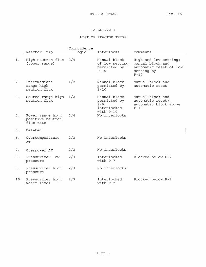
BVPS-2 UFSAR Rev. 16
1 of 3
TABLE 7.2-1
LIST OF REACTOR TRIPS
Reactor Trip
Coincidence Logic
Interlocks
Comments
1. High neutron flux
(power range) 2/4 Manual block
of low setting permitted by P-10
High and low setting; manual block and automatic reset of low setting by P-10
2. Intermediate range high neutron flux
1/2 Manual block permitted by P-10
Manual block and automatic reset
3. Source range high neutron flux
1/2 Manual block permitted by P-6, interlocked with P-10
Manual block and automatic reset; automatic block above P-10
4. Power range high positive neutron flux rate
2/4 No interlocks
5. Deleted
6. Overtemperature ΔT
2/3 No interlocks
7. Overpower ΔT 2/3 No interlocks
8. Pressurizer low pressure
2/3 Interlocked with P-7
Blocked below P-7
9. Pressurizer high pressure
2/3 No interlocks
10. Pressurizer high water level
2/3 Interlocked with P-7
Blocked below P-7
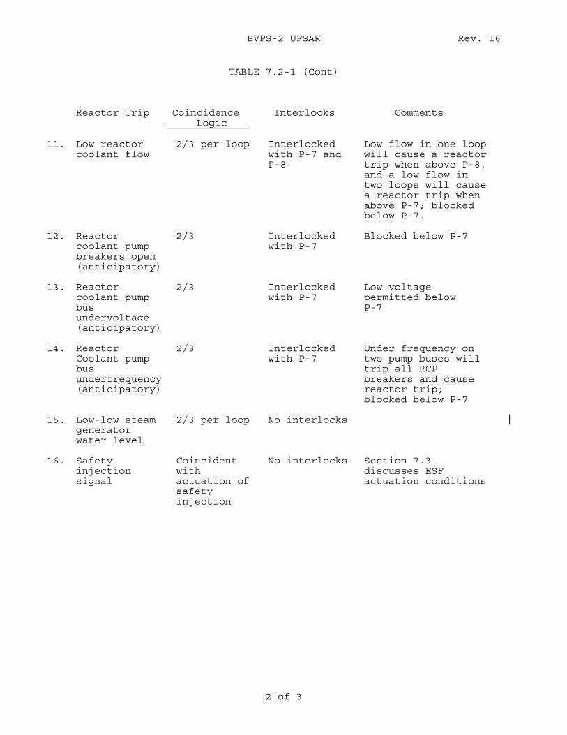
BVPS-2 UFSAR Rev. 16
2 of 3
TABLE 7.2-1 (Cont)
Reactor Trip
Coincidence Logic
Interlocks
Comments
11. Low reactor
coolant flow 2/3 per loop Interlocked
with P-7 and P-8
Low flow in one loop will cause a reactor trip when above P-8, and a low flow in two loops will cause a reactor trip when above P-7; blocked below P-7.
12. Reactor coolant pump breakers open (anticipatory)
2/3 Interlocked with P-7
Blocked below P-7
13. Reactor coolant pump bus undervoltage (anticipatory)
2/3 Interlocked with P-7
Low voltage permitted below P-7
14. Reactor Coolant pump bus underfrequency (anticipatory)
2/3 Interlocked with P-7
Under frequency on two pump buses will trip all RCP breakers and cause reactor trip; blocked below P-7
15. Low-low steam generator water level
2/3 per loop No interlocks
16. Safety injection signal
Coincident with actuation of safety injection
No interlocks Section 7.3 discusses ESF actuation conditions
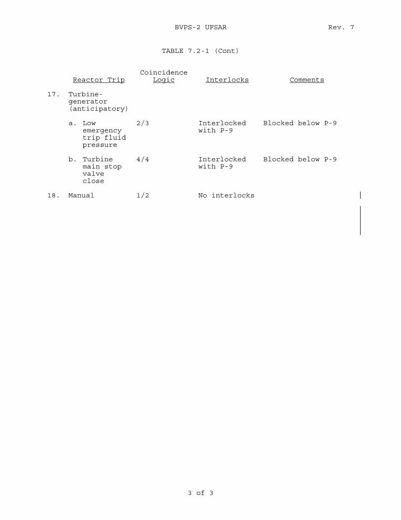
BVPS-2 UFSAR Rev. 7
3 of 3
TABLE 7.2-1 (Cont)
Reactor Trip
Coincidence
Logic
Interlocks
Comments 17. Turbine-
generator (anticipatory)
a. Low emergency trip fluid pressure
2/3 Interlocked with P-9
Blocked below P-9
b. Turbine main stop valve close
4/4 Interlocked with P-9
Blocked below P-9
18. Manual 1/2 No interlocks
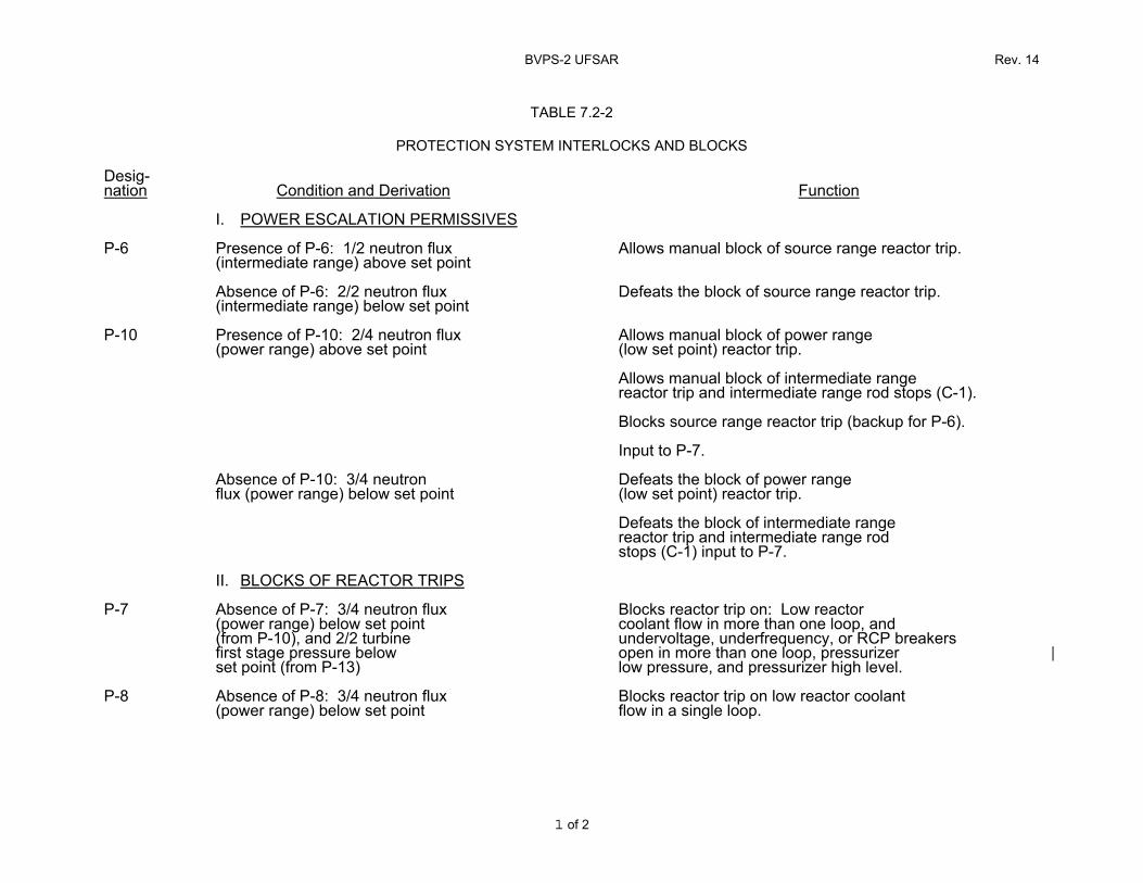
BVPS-2 UFSAR Rev. 14
1 of 2
TABLE 7.2-2
PROTECTION SYSTEM INTERLOCKS AND BLOCKS Desig- nation
Condition and Derivation
Function
I. POWER ESCALATION PERMISSIVES
P-6 Presence of P-6: 1/2 neutron flux (intermediate range) above set point
Allows manual block of source range reactor trip.
Absence of P-6: 2/2 neutron flux (intermediate range) below set point
Defeats the block of source range reactor trip.
P-10 Presence of P-10: 2/4 neutron flux (power range) above set point
Allows manual block of power range (low set point) reactor trip.
Allows manual block of intermediate range reactor trip and intermediate range rod stops (C-1).
Blocks source range reactor trip (backup for P-6).
Input to P-7.
Absence of P-10: 3/4 neutron flux (power range) below set point
Defeats the block of power range (low set point) reactor trip.
Defeats the block of intermediate range reactor trip and intermediate range rod stops (C-1) input to P-7.
II. BLOCKS OF REACTOR TRIPS
P-7 Absence of P-7: 3/4 neutron flux (power range) below set point (from P-10), and 2/2 turbine first stage pressure below set point (from P-13)
Blocks reactor trip on: Low reactor coolant flow in more than one loop, and undervoltage, underfrequency, or RCP breakers open in more than one loop, pressurizer low pressure, and pressurizer high level.
P-8 Absence of P-8: 3/4 neutron flux (power range) below set point
Blocks reactor trip on low reactor coolant flow in a single loop.
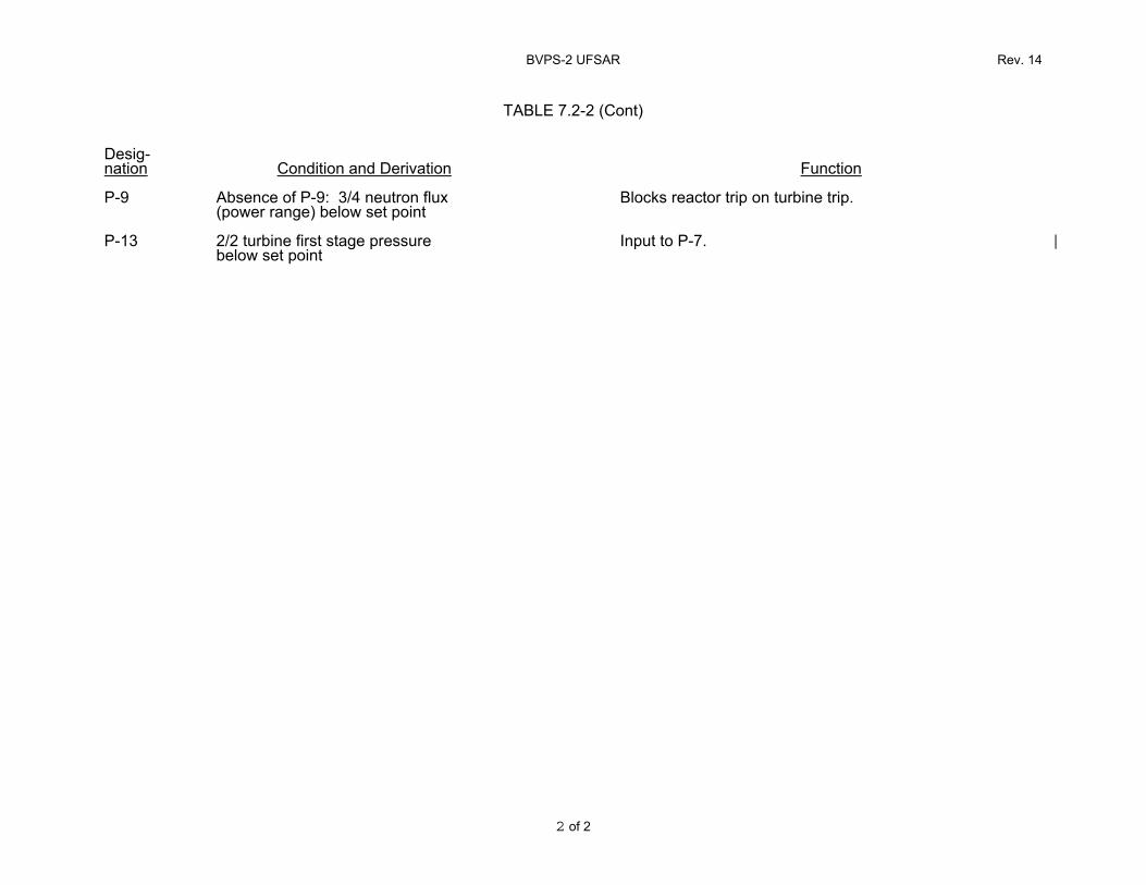
BVPS-2 UFSAR Rev. 14
2 of 2
TABLE 7.2-2 (Cont)
Desig- nation
Condition and Derivation
Function
P-9 Absence of P-9: 3/4 neutron flux
(power range) below set point
Blocks reactor trip on turbine trip.
P-13 2/2 turbine first stage pressure below set point
Input to P-7.
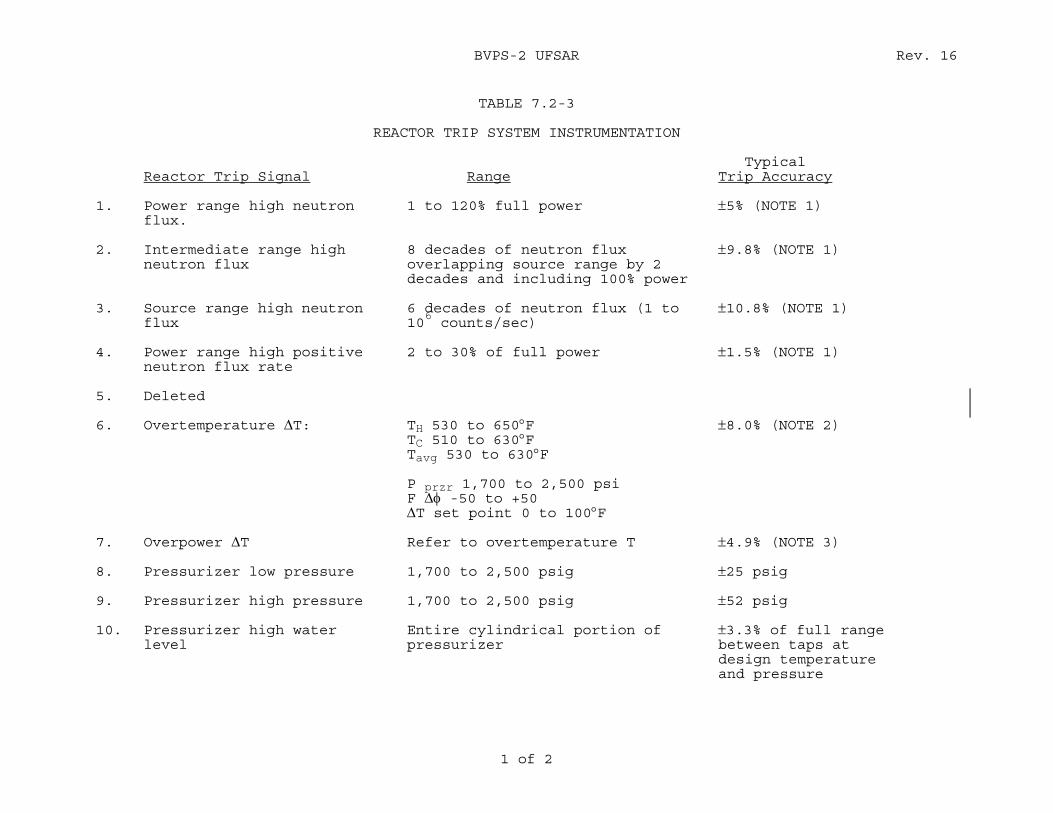
BVPS-2 UFSAR Rev. 16
1 of 2
TABLE 7.2-3
REACTOR TRIP SYSTEM INSTRUMENTATION Typical Reactor Trip Signal Range Trip Accuracy 1. Power range high neutron 1 to 120% full power ±5% (NOTE 1) flux. 2. Intermediate range high 8 decades of neutron flux ±9.8% (NOTE 1) neutron flux overlapping source range by 2 decades and including 100% power 3. Source range high neutron 6 decades of neutron flux (1 to ±10.8% (NOTE 1) flux 10
6 counts/sec)
4. Power range high positive 2 to 30% of full power ±1.5% (NOTE 1) neutron flux rate 5. Deleted 6. Overtemperature ΔT: TH 530 to 650°F ±8.0% (NOTE 2) TC 510 to 630°F Tavg 530 to 630°F P przr 1,700 to 2,500 psi F Δφ -50 to +50 ΔT set point 0 to 100°F 7. Overpower ΔT Refer to overtemperature T ±4.9% (NOTE 3) 8. Pressurizer low pressure 1,700 to 2,500 psig ±25 psig 9. Pressurizer high pressure 1,700 to 2,500 psig ±52 psig 10. Pressurizer high water Entire cylindrical portion of ±3.3% of full range level pressurizer between taps at design temperature and pressure
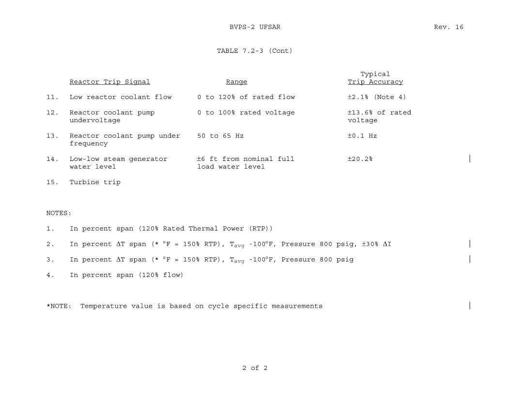
BVPS-2 UFSAR Rev. 16
2 of 2
TABLE 7.2-3 (Cont)
Typical Reactor Trip Signal Range Trip Accuracy 11. Low reactor coolant flow 0 to 120% of rated flow ±2.1% (Note 4) 12. Reactor coolant pump 0 to 100% rated voltage ±13.6% of rated undervoltage voltage 13. Reactor coolant pump under 50 to 65 Hz ±0.1 Hz frequency 14. Low-low steam generator ±6 ft from nominal full ±20.2% water level load water level 15. Turbine trip NOTES: 1. In percent span (120% Rated Thermal Power (RTP)) 2. In percent ΔT span (* °F = 150% RTP), Tavg -100°F, Pressure 800 psig, ±30% ΔI 3. In percent ΔT span (* °F = 150% RTP), Tavg -100°F, Pressure 800 psig 4. In percent span (120% flow) *NOTE: Temperature value is based on cycle specific measurements
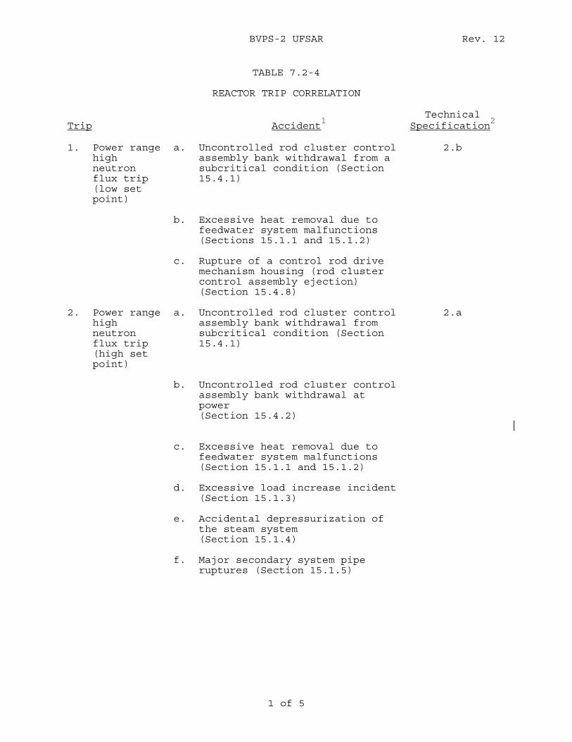
BVPS-2 UFSAR Rev. 12
1 of 5
TABLE 7.2-4
REACTOR TRIP CORRELATION Trip
Accident
1
Technical Specification
2
1. Power range
high neutron flux trip (low set point)
a. Uncontrolled rod cluster control assembly bank withdrawal from a subcritical condition (Section 15.4.1)
2.b
b. Excessive heat removal due to feedwater system malfunctions (Sections 15.1.1 and 15.1.2)
c. Rupture of a control rod drive mechanism housing (rod cluster control assembly ejection) (Section 15.4.8)
2. Power range high neutron flux trip (high set point)
a. Uncontrolled rod cluster control assembly bank withdrawal from subcritical condition (Section 15.4.1)
2.a
b. Uncontrolled rod cluster control assembly bank withdrawal at power (Section 15.4.2)
c. Excessive heat removal due to feedwater system malfunctions (Section 15.1.1 and 15.1.2)
d. Excessive load increase incident (Section 15.1.3)
e. Accidental depressurization of the steam system (Section 15.1.4)
f. Major secondary system pipe ruptures (Section 15.1.5)
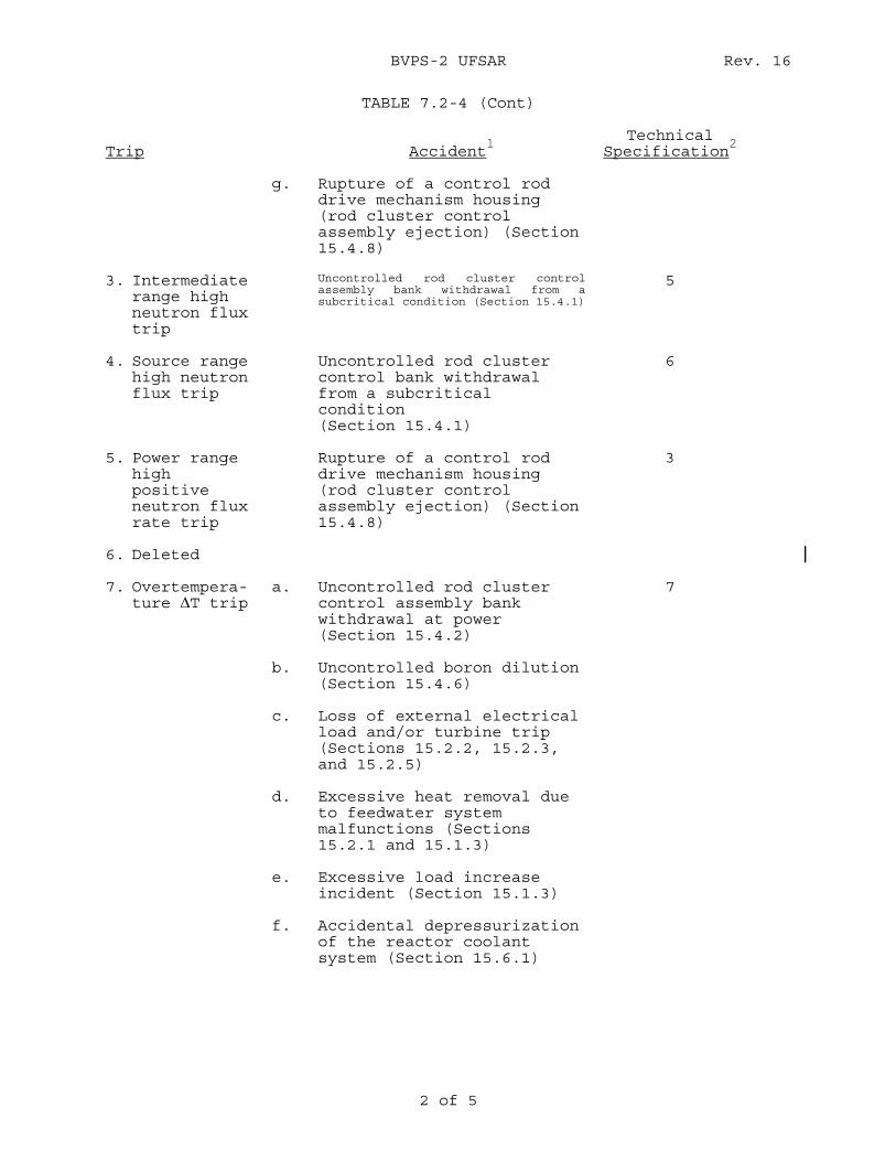
BVPS-2 UFSAR Rev. 16
2 of 5
TABLE 7.2-4 (Cont) Trip
Accident
1
Technical Specification
2
g. Rupture of a control rod
drive mechanism housing (rod cluster control assembly ejection) (Section 15.4.8)
3. Intermediate range high neutron flux trip
Uncontrolled rod cluster control assembly bank withdrawal from a subcritical condition (Section 15.4.1)
5
4. Source range high neutron flux trip
Uncontrolled rod cluster control bank withdrawal from a subcritical condition (Section 15.4.1)
6
5. Power range high positive neutron flux rate trip
Rupture of a control rod drive mechanism housing (rod cluster control assembly ejection) (Section 15.4.8)
3
6. Deleted
7. Overtempera-ture ΔT trip
a. Uncontrolled rod cluster control assembly bank withdrawal at power (Section 15.4.2)
7
b. Uncontrolled boron dilution (Section 15.4.6)
c. Loss of external electrical load and/or turbine trip (Sections 15.2.2, 15.2.3, and 15.2.5)
d. Excessive heat removal due to feedwater system malfunctions (Sections 15.2.1 and 15.1.3)
e. Excessive load increase incident (Section 15.1.3)
f. Accidental depressurization of the reactor coolant system (Section 15.6.1)
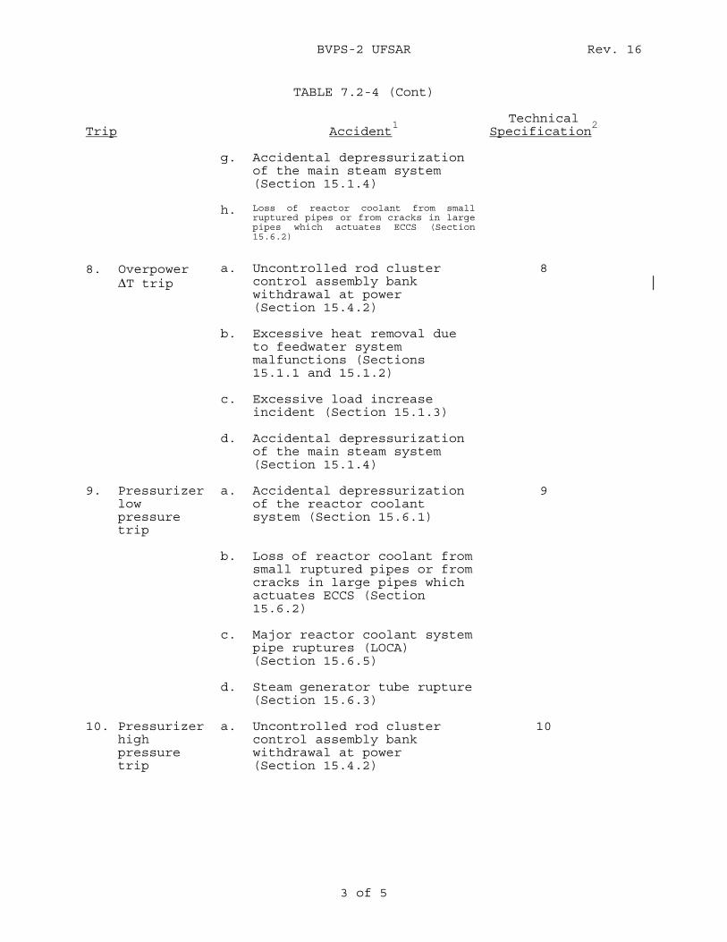
BVPS-2 UFSAR Rev. 16
3 of 5
TABLE 7.2-4 (Cont) Trip
Accident
1
Technical Specification
2
g. Accidental depressurization
of the main steam system (Section 15.1.4)
h. Loss of reactor coolant from small ruptured pipes or from cracks in large pipes which actuates ECCS (Section 15.6.2)
8. Overpower ΔT trip
a. Uncontrolled rod cluster control assembly bank withdrawal at power (Section 15.4.2)
8
b. Excessive heat removal due to feedwater system malfunctions (Sections 15.1.1 and 15.1.2)
c. Excessive load increase incident (Section 15.1.3)
d. Accidental depressurization of the main steam system (Section 15.1.4)
9. Pressurizer
low pressure trip
a. Accidental depressurization of the reactor coolant system (Section 15.6.1)
9
b. Loss of reactor coolant from small ruptured pipes or from cracks in large pipes which actuates ECCS (Section 15.6.2)
c. Major reactor coolant system pipe ruptures (LOCA) (Section 15.6.5)
d. Steam generator tube rupture (Section 15.6.3)
10. Pressurizer high pressure trip
a. Uncontrolled rod cluster control assembly bank withdrawal at power (Section 15.4.2)
10
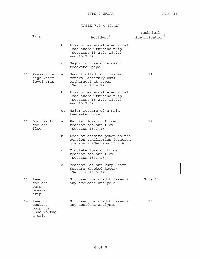
BVPS-2 UFSAR Rev. 16
4 of 5
TABLE 7.2-4 (Cont) Trip
Accident
1
Technical Specification
2
b. Loss of external electrical
load and/or turbine trip (Sections 15.2.2, 15.2.3, and 15.2.5)
c. Major rupture of a main feedwater pipe
11. Pressurizer high water level trip
a. Uncontrolled rod cluster control assembly bank withdrawal at power (Section 15.4.2)
11
b. Loss of external electrical load and/or turbine trip (Sections 15.2.2, 15.2.3, and 15.2.5)
c. Major rupture of a main feedwater pipe
12. Low reactor coolant flow
a. Partial loss of forced reactor coolant flow (Section 15.3.1)
12
b. Loss of offsite power to the station auxiliaries (station blackout) (Section 15.2.6)
c. Complete loss of forced reactor coolant flow (Section 15.3.2)
d. Reactor Coolant Pump Shaft Seizure (Locked Rotor) (Section 15.3.3)
13. Reactor coolant pump breaker trip
Not used nor credit taken in any accident analysis
Note 3
14. Reactor coolant pump bus undervoltage trip
Not used nor credit taken in any accident analysis
15
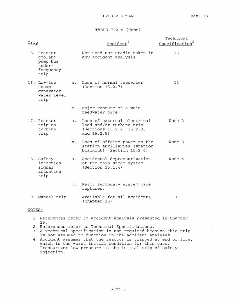
BVPS-2 UFSAR Rev. 17
5 of 5
TABLE 7.2-4 (Cont) Trip
Accident
1
Technical Specification
2
15. Reactor
coolant pump bus under-frequency trip
Not used nor credit taken in any accident analysis
16
16. Low-low steam generator water level trip
a. Loss of normal feedwater (Section 15.2.7)
13
b. Major rupture of a main feedwater pipe.
17. Reactor trip on turbine trip
a. Loss of external electrical load and/or turbine trip (Sections 15.2.2, 15.2.3, and 15.2.5)
Note 3
b. Loss of offsite power to the station auxiliaries (station blackout) (Section 15.2.6)
Note 3
18. Safety injection signal actuation trip
a. Accidental depressurization of the main steam system (Section 15.1.4)
Note 4
b. Major secondary system pipe ruptures.
19. Manual trip Available for all accidents (Chapter 15)
1
NOTES: 1 References refer to accident analysis presented in Chapter
15. 2 References refer to Technical Specifications. 3 A Technical Specification is not required because this trip
is not assumed to function in the accident analyses. 4 Accident assumes that the reactor is tripped at end of life,
which is the worst initial condition for this case. Pressurizer low pressure is the initial trip of safety injection.
BVPS-2 UFSAR Rev. 9
REFER TO FIGURE 7.3-6
FIGURE 7.2-1 (SH. 1 OF 18) FUNCTIONAL DIAGRAM INDEX AND SYMBOLS BEAVER VALLEY POWER STATION - UNIT 2 FINAL SAFETY ANALYSIS REPORT

BVPS-2 UFSAR Rev. 9
REFER TO FIGURE 7.3-7
FIGURE 7.2-1 (SH. 2 OF 18) FUNCTIONAL DIAGRAM REACTOR TRIP SIGNALS BEAVER VALLEY POWER STATION - UNIT 2 FINAL SAFETY ANALYSIS REPORT

BVPS-2 UFSAR Rev. 9
REFER TO FIGURE 7.3-8
FIGURE 7.2-1 (SH. 3 OF 18) FUNCTIONAL DIAGRAM NUCLEAR INSTRUMENTATION & MANUAL TRIP SIGNALS BEAVER VALLEY POWER STATION - UNIT 2 FINAL SAFETY ANALYSIS REPORT

BVPS-2 UFSAR Rev. 9
REFER TO FIGURE 7.3-9
FIGURE 7.2-1 (SH. 4 OF 18) FUNCTIONAL DIAGRAM NUCLEAR INSTRUMENTATION PERMISSIVES & BLOCKS BEAVER VALLEY POWER STATION - UNIT 2 FINAL SAFETY ANALYSIS REPORT

BVPS-2 UFSAR Rev. 9
REFER TO FIGURE 7.3-10
FIGURE 7.2-1 (SH. 5 OF 18) FUNCTIONAL DIAGRAM PRIMARY COOLANT SYSTEM TRIP SIGNALS BEAVER VALLEY POWER STATION - UNIT 2 FINAL SAFETY ANALYSIS REPORT

BVPS-2 UFSAR Rev. 9
REFER TO FIGURE 7.3-11
FIGURE 7.2-1 (SH. 6 OF 18) FUNCTIONAL DIAGRAM PRESSURIZER TRIP SIGNALS BEAVER VALLEY POWER STATION - UNIT 2 FINAL SAFETY ANALYSIS REPORT

BVPS-2 UFSAR Rev. 9
REFER TO FIGURE 7.3-12
FIGURE 7.2-1 (SH. 7 OF 18) FUNCTIONAL DIAGRAM STEAM GENERATOR TRIP SIGNALS BEAVER VALLEY POWER STATION - UNIT 2 FINAL SAFETY ANALYSIS REPORT

BVPS-2 UFSAR Rev. 9
REFER TO FIGURE 7.3-13
FIGURE 7.2-1 (SH. 8 OF 18) FUNCTIONAL DIAGRAM SAFEGUARD ACTUATION SIGNALS BEAVER VALLEY POWER STATION - UNIT 2 FINAL SAFETY ANALYSIS REPORT

BVPS-2 UFSAR Rev. 9
REFER TO FIGURE 7.3-14
FIGURE 7.2-1 (SH. 9 OF 18) FUNCTIONAL DIAGRAM ROD CONTROLS & ROD BLOCKS BEAVER VALLEY POWER STATION - UNIT 2 FINAL SAFETY ANALYSIS REPORT

BVPS-2 UFSAR Rev. 9
REFER TO FIGURE 7.3-15
FIGURE 7.2-1 (SH. 10 OF 18) FUNCTIONAL DIAGRAM STEAM DUMP CONTROL BEAVER VALLEY POWER STATION - UNIT 2 FINAL SAFETY ANALYSIS REPORT

BVPS-2 UFSAR Rev. 9
REFER TO FIGURE 7.3-16
FIGURE 7.2-1 (SH. 11 OF 18) FUNCTIONAL DIAGRAM PRESSURIZER PRESSURE & t.EVEL CONTROL BEAVER VALLEY POWER STATION - UNIT 2 FINAL SAFETY ANALYSIS REPORT
BVPS-2 UFSAR Rev. 9
REFER TO FIGURE 7.3-17
FIGURE 7.2-1 (SH. 12 OF 18) FUNCTIONAL DIAGRAM PRESSURIZER HEATER CONTROL BEAVER VALLEY POWER STATION - UNIT 2 FINAL SAFETY ANALYSIS REPORT
BVPS-2 UFSAR Rev. 9
REFER TO FIGURE 7.3-18
FIGURE 7.2-1 (SH. 13 OF 18) FUNCTIONAL DIAGRAM FEEDWATER CONTROL & ISOLATION BEAVER VALLEY POWER STATION - UNIT 2 FINAL SAFETY ANALYSIS REPORT

BVPS-2 UFSAR Rev. 9
REFER TO FIGURE 7.3-19
FIGURE 7.2-1 (SH. 14 OF 18) FUNCTIONAL DIAGRAM AUXILIARY FEEDWATER PUMPS STARTUP BEAVER VALLEY POWER STATION - UNIT 2 FINAL SAFETY ANALYSIS REPORT
BVPS-2 UFSAR Rev. 9
REFER TO FIGURE 7.3-20
FIGURE 7.2-1 (SH. 15 OF 18) FUNCTIONAL DIAGRAM TURBINE TRIP RUNBACKS & OTHER SIGNALS (W REQUIREMENTS) BEAVER VALLEY POWER STATION - UNIT 2 FINAL SAFETY ANALYSIS REPORT

BVPS-2 UFSAR Rev. 9
REFER TO FIGURE 7.3-21
FIGURE 7.2-1 (SH. 16 OF 18) FUNCTIONAL DIAGRAM LOOP STOP VALVE LOGIC BEAVER VALLEY POWER STATION - UNIT 2 FINAL SAFETY ANALYSIS REPORT

BVPS-2 UFSAR Rev. 9
REFER TO FIGURE 7.3-23
FIGURE 7.2-1 (SH. 17 OF 18) FUNCTIONAL DIAGRAM PRESSURIZER PRESSURE RELIEF SYSTEM (TRAIN "A") BEAVER VALLEY POWER STATION - UNIT 2 FINAL SAFETY ANALYSIS REPORT
BVPS-2 UFSAR Rev. 9
REFER TO FIGURE 7.3-22
FIGURE 7.2-1 (SH. 18 OF 18) FUNCTIONAL DIAGRAM PRESSURIZER PRESSURE RELIEF SYSTEM (TRAIN "8") BEAVER VALLEY POWER STATION - UNIT 2 FINAL SAFETY ANALYSIS REPORT
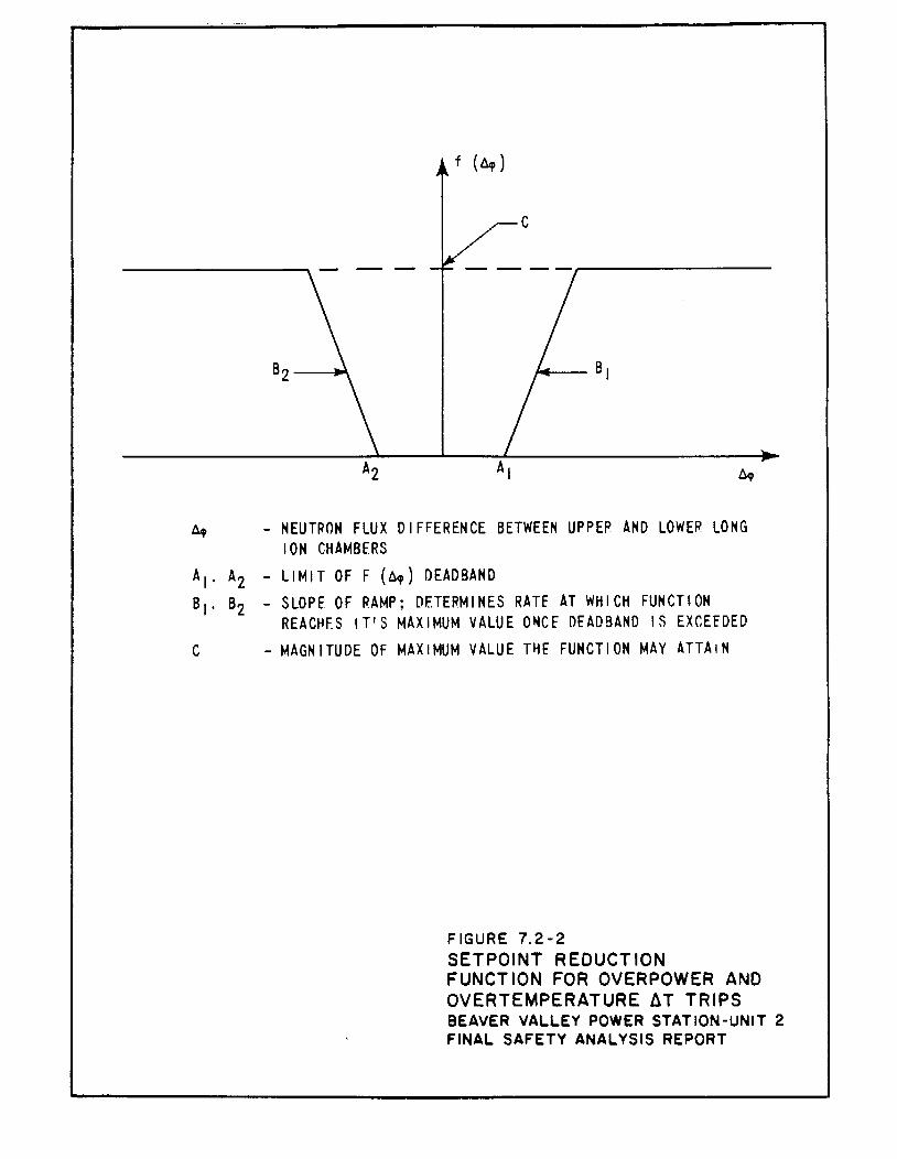
f (l1f)
c
t1q. - NEUTRON FLUX DIFFERENCE BETWEEN UPPER AND LOWER LONG ION CHAMBERS
A1. Az -LIMIT OFF (6,) DEADBAND B1. Bz - SLOPE OF RAMP; DETERMINES RATE AT WHICH FUNCTION
REAC~ES IT'S MAXIMUM VALUE O~CE DfADBAND IS EXCEEDED C -MAGNITUDE OF MAXIMUM VALUE T~f FUNCTION MAY ATTAIN
FIGURE 7.2·2 SETPOINT REDUCTION FUNCTION FOR OVERPOWER AND OVERTEMPERATURE ~T TRIPS BEAVER VALLEY POWER STATION-UNIT 2 FINAL SAFETY ANALYSIS REPORT
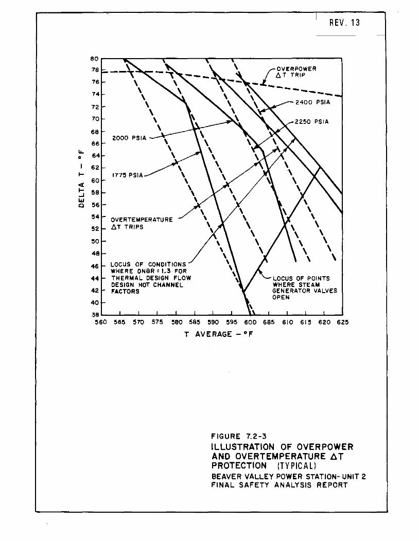
u. 0
I ..... <( ..... ...J
"" 0
eo 78
76
72
70
68
66
62
60
58
52
50
46
44
42
40
OVERTEMPERATURE ~T TRIPS
LOCUS OF CONDITIONS WHERE DNBR = 1.3 FOR THERMAL DESIGN FLOW DESIGN HOT CHANNEL FACTORS
REV. 13
LOCUS OF POINTS WHERE STEAM GENERATOR VALVES OPEN
38~~--~--~--~--~--~~--_.~~--~--~~--~ 560 !565 570 575 580 585 590 595 600 685 610 615 620 625
T AVERAGE -°F
FIGURE 7.2-3 ILLUSTRATION OF OVERPOWER AND OVERTEMPERATURE fl. T PROTECTION (TYPICAL) BEAVER VALLEY POWER STATION- UNIT 2 FINAL SAFETY ANALYSIS REPORT
BVPS-2 UFSAR Rev. 16
7.3-1
7.3 ENGINEERED SAFETY FEATURES ACTUATION SYSTEM In addition to the requirements for a reactor trip for anticipated abnormal transients, the facility shall be provided with adequate instrumentation and controls to sense accident situations and initiate the operation of necessary engineered safety features (ESF). The occurrence of a limiting fault, such as a loss-of-coolant accident (LOCA) or a main steam line break (MSLB), requires a reactor trip plus actuation of one or more of the ESF in order to prevent or mitigate damage to the core and reactor coolant system (RCS) components, and ensure containment integrity. In order to accomplish these design objectives the engineered safety features actuation system (ESFAS) shall have proper and timely initiating signals which are to be supplied by the sensors, transmitters, and logic components making up the various instrumentation channels of the ESFAS. Figures 7.3-6, 7.3-7, 7.3-8, 7.3-9, 7.3-10, 7.3-11, 7.3-12, 7.3-13, 7.3-14, 7.3-15, 7.3-16, 7.3-17, 7.3-18, 7.3-19, 7.3-20, 7.3-21, 7.3-22 and 7.3-23 show Westinghouse Electric Corporation functional diagrams and 7.3-24, 7.3-25, 7.3-26, 7.3-27, 7.3-28, 7.3-29, 7.3-30, 7.3-31, 7.3-32, 7.3-33, 7.3-34, 7.3-35, 7.3-36, 7.3-37, 7.3-38, 7.3-39, 7.3-40, 7.3-41, 7.3-42, 7.3-43, 7.3-44, 7.3-45, 7.3-46, 7.3-47, 7.3-48, 7.3-49, 7.3-50, 7.3-51, 7.3-52, 7.3-52a, 7.3-53, 7.3-54, 7.3-55, 7.3-56, 7.3-56a, 7.3-57, 7.3-58, 7.3-59, 7.3-60, 7.3-61, 7.3-62, 7.3-63, 7.3-64, 7.3-65, 7.3-66, 7.3-67, 7.3-68, 7.3-69, 7.3-70, 7.3-71, 7.3-72, 7.3-72a, 7.3-72b, 7.3-72c, 7.3-73, 7.3-74, 7.3-75, 7.3-76, 7.3-77, 7.3-77a, 7.3-78, 7.3-79, 7.3-80, 7.3-81, 7.3-82, 7.3-82a, 7.3-82b, 7.3-82c, 7.3-83, 7.3-84, 7.3-85, 7.3-86, 7.3-86a, 7.3-87, 7.3-88, 7.3-89, 7.3-90, 7.3-91, 7.3-92, 7.3-93, 7.3-94 and 7.3-95 show logic diagrams for the ESFAS. 7.3.1 Description The ESFAS uses selected plant parameters, determines whether or not predetermined safety limits are being exceeded and, if they are, combines the signals into logic matrices sensitive to combinations indicative of primary or secondary system boundary ruptures (Condition III or IV faults). Once the required logic combination is completed, the system sends actuation signals to the appropriate ESF components. The ESFAS meets the functional requirements of General Design Criteria (GDC) 13, 20, 27, and 38. 7.3.1.1 System Description The ESFAS is a functionally defined system described in this section. The equipment which provides the actuation functions identified in Section 7.3.1.1.1 is listed as follows and is discussed in this section.
1. Process instrumentation and control system (Reid 1973), 2. Solid state protection system (Katz 1971), 3. Engineered safety features test cabinet (Mesmeringer 1980),
and 4. Manual actuation circuits.
BVPS-2 UFSAR Rev. 13
7.3-2
The ESFAS consists of two discrete portions of circuitry: 1) an analog portion consisting of three to four redundant channels per parameter or variable to monitor various Beaver Valley Power Station - Unit 2 (BVPS-2) parameters such as the RCS and steam system pressures, temperatures, and flows, and containment pressures, and 2) a portion consisting of two redundant logic trains which receive inputs from the analog protection channels and perform the logic needed to actuate the ESF. Each actuation train is capable of actuating the minimum ESF equipment required, thereby assuring that any single failure within either of the redundant trains shall not result in the defeat of the required protective function. The redundant concept is applied to both the analog and logic portions of the system. Separation of redundant analog channels begins at the process sensors and is maintained in the field wiring, containment vessel penetrations, and analog protection racks, terminating at the redundant group of logic racks. The design meets the requirements of GDC 20, 21, 22, 23, and 24. The variables are sensed by the analog circuitry as discussed in WCAP-7913 (Reid 1973) and in Section 7.2. The outputs from the analog channels are combined into actuation logic as shown on Figure 7.2-1, Sheets 5, 6, 7, and 8. Tables 7.3-1 and 7.3-2 give additional information pertaining to logic and function. The interlocks associated with the ESFAS are outlined in Table 7.3-3. These interlocks satisfy the functional requirements discussed in Section 7.1.2. System level manual initiation from the main control board is provided for the following systems: Safety Injection Two switches, operating either switch will actuate. Containment Isolation Phase A Two switches, operating either switch will actuate. Control Room Isolation Two switches, operating either switch will actuate. Steam Line Isolation Four switches, operating two associated switches per train, simultaneously controls all steam line isolation valves (SLIVs) and bypass valves. Containment Spray and Containment Isolation Phase B Four switches, actuation will occur if two associated controls are operated simultaneously. For the transfer of emergency core cooling system (ECCS) injection to the recirculation mode, refer to Sections 6.3.2.8 and 7.6.5 and Table 6.3-7.
BVPS-2 UFSAR Rev. 17
7.3-3
7.3.1.1.1 Function Initiation The specific functions which rely on the ESFAS for initiation are:
1. A reactor trip, provided one has not already been generated by the reactor trip system.
2. Cold leg injection isolation valves, which are opened to
align the charging pumps for high pressure safety injection into the cold legs of the RCS.
3. Charging pumps, low head safety injection (LHSI) pumps, and
associated valving, which provide emergency makeup water to the cold legs of the RCS following a LOCA.
4. Automatic transfer of ECCS injection to recirculation on
extreme low refueling water storage tank (RWST) level. 5. Pumps and valves, which serve as part of the heat sink and as
part of the heat sink for containment cooling, for example, service water pumps.
6. Motor-driven auxiliary feedwater pumps and associated valves
and the valves required to initiate a steam supply to the turbine-driven auxiliary feedwater pump.
7. Containment isolation Phase A, whose function is to prevent
fission product release. (Isolation of all lines not essential to reactor protection.)
8. Steam line isolation to prevent the continuous, uncontrolled
blowdown of more than one steam generator and thereby uncontrolled RCS cooldown.
9. Main feedwater line isolation, as required, to prevent or
mitigate the effects of excessive cooldown. 10. Start-up of the emergency diesel generators to assure the
backup supply of power to emergency and supporting systems components.
11. Isolation of the main control room air ducts to meet control
room occupancy requirements and start of the emergency ventilation fans to pressurize the control room.
BVPS-2 UFSAR Rev. 18
7.3-4
12. Containment quench and recirculation spray systems, which performs the following functions:
a. Initiate quench and recirculation sprays to reduce
containment pressure and temperature following a LOCA or MSLB accident inside containment.
b. Initiates containment isolation Phase B which, except
for ESF lines penetrating containment, isolates the containment following a LOCA, or an MSLB or feedwater line break within containment to limit radioactive releases. (Section 6.2.4 considers isolation valves in further detail.)
13. Sequencers for loss of offsite power (LOOP) or safety
injection (Chapter 8). 7.3.1.1.2 Analog Circuitry The process analog sensors and racks for the ESFAS are discussed in WCAP-7913 (Reid 1973). Discussed in this report are the parameters to be measured including pressures, flows, tank and vessel water levels, and temperatures, as well as the measurement and signal transmission considerations. Other considerations discussed are automatic calculations, signal conditioning and location, and mounting of the devices. The sensors monitoring the primary system are located as shown on the piping flow diagrams in Chapter 5, Reactor Coolant System and Connected Systems. The secondary system sensor locations are shown on the steam system flow diagrams given in Chapter 10. There are four instrument lines which penetrate the containment and which are required to remain functional following a LOCA or MSLB inside containment. These lines sense the pressure of containment atmosphere on the inside and are connected to pressure transmitters on the outside. Signals from these transmitters can initiate safety injection and containment isolation on Hi-1 containment pressure, and initiate main steam line isolation on Hi-2 containment pressure. These signals also, upon Hi-3 containment pressure, produce the automatic signal to initiate containment depressurization system spray and provide for post-accident monitoring (PAM) of containment pressure. In view of these functions, these lines do not have automatic isolation valves since it is essential that the lines remain open and not be isolated following an accident. This system is described in Section 6.2.4. 7.3.1.1.3 Digital Circuitry The ESF logic racks are discussed in detail in WCAP-7488-L (Katz 1971). The description includes the considerations and provisions
BVPS-2 UFSAR Rev. 18
7.3-5
for physical and electrical separation as well as details of the circuitry. Katz (1971) also discusses certain aspects of on-line test provisions, provisions for test points, considerations for the instrument power source, and considerations for accomplishing physical separation. The outputs from the analog channels are combined into actuation logic as shown on Figure 7.2-1, Sheets 5 (Tavg), 6 (Pressurizer Pressure), 7 (Low Steam Line Pressure), 8 (Engineered Safety Features Actuation), and 14 (Auxiliary Feedwater). To facilitate ESF actuation testing, two cabinets (one per train) are provided which enable operation, to the maximum extent practical, of safety features loads on a group by group basis until actuation of all devices has been checked. Final actuation testing is discussed in detail in Section 7.3.2. 7.3.1.1.4 Final Actuation Circuitry The outputs of the solid-state protection system (SSPS) (the slave relays) are energized to actuate, as are most final actuators and actuated devices. These devices are listed as follows:
1. Safety injection system pump and valve actuators. (Chapter 6 provides flow diagrams and additional information).
2. Containment isolation Phase A and Phase B (Chapter 6.) 3. Automatic transfer of ECCS injection to recirculation on
extreme low RWST level. 4. Service water pump and valve actuators (Chapter 9). 5. Auxiliary feedwater pumps start (Chapter 10). 6. Emergency diesel generators start (Chapter 8). 7. Feedwater isolation (Chapter 10). 8. Main control room ventilation isolation valve and damper
actuators (Chapter 6). 9. Steam line isolation valve actuators (Chapter 10). 10. Containment quench spray, recirculation spray, and valve
actuators (Chapter 6). If an accident is assumed to occur coincident with a LOOP, the ESF loads are sequenced onto the emergency diesel generators to prevent overloading them. This sequence is discussed in Chapter 8. The design meets the requirements of GDC 35.
BVPS-2 UFSAR Rev. 0
7.3-6
7.3.1.1.5 Support Systems The following systems are required for support of the ESF:
1. Service water - heat removal (Section 9.2.1). 2. Safety-related ventilation systems (Section 9.4). 3. Electrical power distribution systems (Section 8.3). 4. Emergency diesel generator fuel oil system (Section 9.5.4).
7.3.1.2 Design Bases Information The functional diagrams presented on Figure 7.2-1, Sheets 5, 6, 7, and 8 provide a graphic outline of the functional logic associated with requirements for the ESFAS. Requirements for the ESF systems are given in Chapter 6. Given by the following is the design bases information required by the Institute of Electrical and Electronics Engineers (IEEE) Standard 279-1971. 7.3.1.2.1 Generating Station Conditions The following is a summary of those generating station conditions requiring protective action from the ESFAS to mitigate an accident (for transient termination, refer to Section 7.2).
1. Primary System: a. Rupture in small pipes or cracks in large pipes, b. Rupture of a reactor coolant pipe (LOCA), and c. Steam generator tube rupture.
2. Secondary System: a. Minor secondary system pipe breaks resulting in steam
release rates equivalent to a single dump, relief, or safety valve,
b. Rupture of a major steam pipe, and c. Rupture of a major feedwater pipe. 7.3.1.2.2 Generating Station Variables The following list summarizes the generating station variables required to be monitored for the automatic initiation of ESF during each accident identified in the preceding section. Requirements for PAM are given in Table 7.5-1.
BVPS-2 UFSAR Rev. 16
7.3-7
1. Primary system accidents: a. Pressurizer pressure, b. RWST water level, and c. Containment pressure (not required for steam generator
tube rupture).
2. Secondary system accidents: a. Pressurizer pressure, b. Steam line pressures and pressure rates, c. Containment pressure, and d. Steam generator water level. 7.3.1.2.3 Limits, Margins, and Levels Prudent operational limits, available margins, and set points before onset of unsafe conditions requiring protective action are discussed in Chapters 15 and 16. 7.3.1.2.4 Abnormal Events The malfunctions, accidents, or other unusual events which could physically damage protection system components or could cause environmental changes are as follows:
1. LOCA (Chapter 15), 2. Secondary system accidents (Chapter 15), 3. Earthquakes (Chapters 2 and 3), 4. Fire (Section 9.5.1), 5. Missiles (Section 3.5), 6. Flood (Chapters 2 and 3), 7. Environmental transients (temperature/pressure/humidity) due
to ventilation system failures (Section 3.11), and 8. High energy line breaks (Section 3.6).
7.3.1.2.5 Minimum Performance Requirements Minimum performance requirements are as follows:
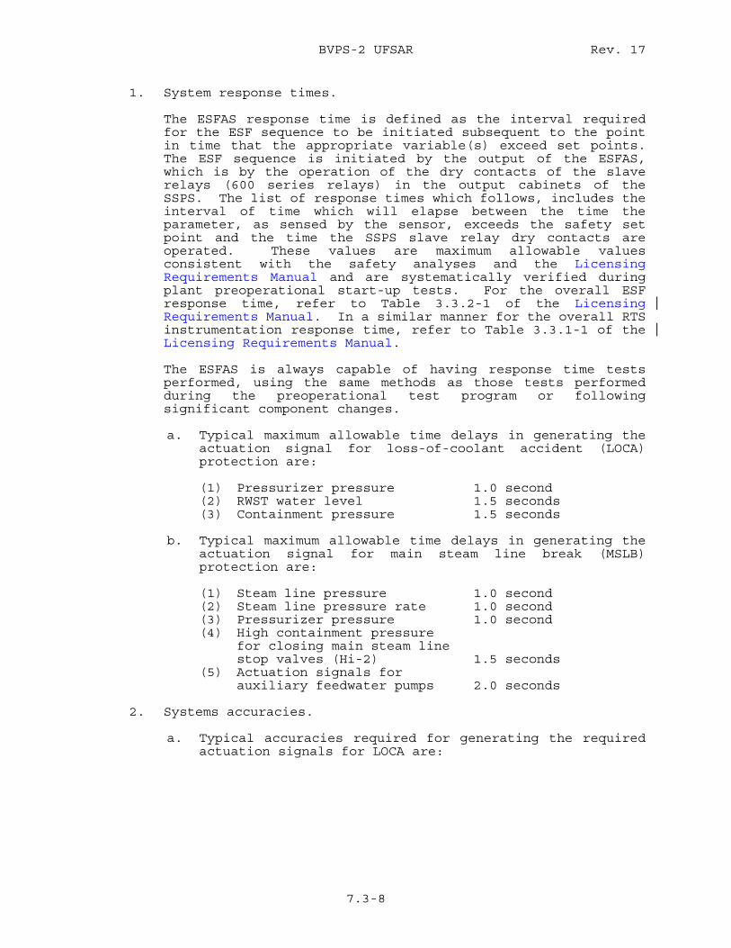
BVPS-2 UFSAR Rev. 17
7.3-8
1. System response times. The ESFAS response time is defined as the interval required
for the ESF sequence to be initiated subsequent to the point in time that the appropriate variable(s) exceed set points. The ESF sequence is initiated by the output of the ESFAS, which is by the operation of the dry contacts of the slave relays (600 series relays) in the output cabinets of the SSPS. The list of response times which follows, includes the interval of time which will elapse between the time the parameter, as sensed by the sensor, exceeds the safety set point and the time the SSPS slave relay dry contacts are operated. These values are maximum allowable values consistent with the safety analyses and the Licensing Requirements Manual and are systematically verified during plant preoperational start-up tests. For the overall ESF response time, refer to Table 3.3.2-1 of the Licensing Requirements Manual. In a similar manner for the overall RTS instrumentation response time, refer to Table 3.3.1-1 of the Licensing Requirements Manual.
The ESFAS is always capable of having response time tests
performed, using the same methods as those tests performed during the preoperational test program or following significant component changes.
a. Typical maximum allowable time delays in generating the
actuation signal for loss-of-coolant accident (LOCA) protection are:
(1) Pressurizer pressure 1.0 second (2) RWST water level 1.5 seconds (3) Containment pressure 1.5 seconds b. Typical maximum allowable time delays in generating the
actuation signal for main steam line break (MSLB) protection are:
(1) Steam line pressure 1.0 second (2) Steam line pressure rate 1.0 second (3) Pressurizer pressure 1.0 second (4) High containment pressure for closing main steam line stop valves (Hi-2) 1.5 seconds (5) Actuation signals for auxiliary feedwater pumps 2.0 seconds
2. Systems accuracies. a. Typical accuracies required for generating the required
actuation signals for LOCA are:
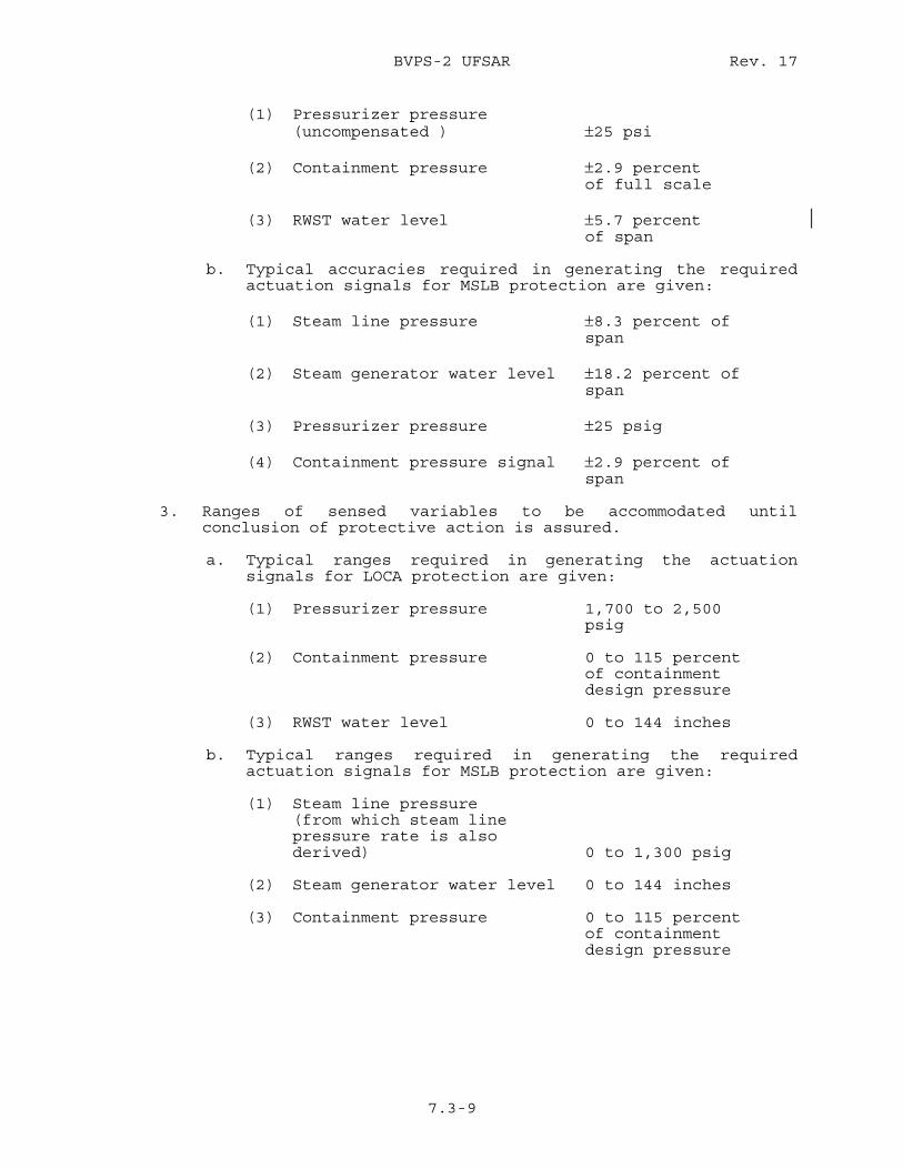
BVPS-2 UFSAR Rev. 17
7.3-9
(1) Pressurizer pressure (uncompensated ) ±25 psi (2) Containment pressure ±2.9 percent of full scale (3) RWST water level ±5.7 percent of span b. Typical accuracies required in generating the required
actuation signals for MSLB protection are given: (1) Steam line pressure ±8.3 percent of span (2) Steam generator water level ±18.2 percent of span (3) Pressurizer pressure ±25 psig (4) Containment pressure signal ±2.9 percent of span
3. Ranges of sensed variables to be accommodated until conclusion of protective action is assured.
a. Typical ranges required in generating the actuation
signals for LOCA protection are given: (1) Pressurizer pressure 1,700 to 2,500 psig (2) Containment pressure 0 to 115 percent of containment design pressure (3) RWST water level 0 to 144 inches b. Typical ranges required in generating the required
actuation signals for MSLB protection are given: (1) Steam line pressure (from which steam line pressure rate is also derived) 0 to 1,300 psig (2) Steam generator water level 0 to 144 inches (3) Containment pressure 0 to 115 percent of containment design pressure
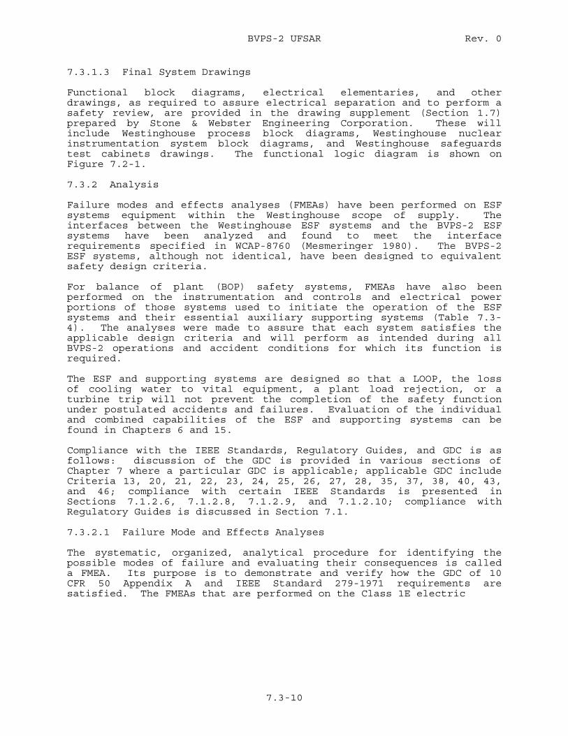
BVPS-2 UFSAR Rev. 0
7.3-10
7.3.1.3 Final System Drawings Functional block diagrams, electrical elementaries, and other drawings, as required to assure electrical separation and to perform a safety review, are provided in the drawing supplement (Section 1.7) prepared by Stone & Webster Engineering Corporation. These will include Westinghouse process block diagrams, Westinghouse nuclear instrumentation system block diagrams, and Westinghouse safeguards test cabinets drawings. The functional logic diagram is shown on Figure 7.2-1. 7.3.2 Analysis Failure modes and effects analyses (FMEAs) have been performed on ESF systems equipment within the Westinghouse scope of supply. The interfaces between the Westinghouse ESF systems and the BVPS-2 ESF systems have been analyzed and found to meet the interface requirements specified in WCAP-8760 (Mesmeringer 1980). The BVPS-2 ESF systems, although not identical, have been designed to equivalent safety design criteria. For balance of plant (BOP) safety systems, FMEAs have also been performed on the instrumentation and controls and electrical power portions of those systems used to initiate the operation of the ESF systems and their essential auxiliary supporting systems (Table 7.3-4). The analyses were made to assure that each system satisfies the applicable design criteria and will perform as intended during all BVPS-2 operations and accident conditions for which its function is required. The ESF and supporting systems are designed so that a LOOP, the loss of cooling water to vital equipment, a plant load rejection, or a turbine trip will not prevent the completion of the safety function under postulated accidents and failures. Evaluation of the individual and combined capabilities of the ESF and supporting systems can be found in Chapters 6 and 15. Compliance with the IEEE Standards, Regulatory Guides, and GDC is as follows: discussion of the GDC is provided in various sections of Chapter 7 where a particular GDC is applicable; applicable GDC include Criteria 13, 20, 21, 22, 23, 24, 25, 26, 27, 28, 35, 37, 38, 40, 43, and 46; compliance with certain IEEE Standards is presented in Sections 7.1.2.6, 7.1.2.8, 7.1.2.9, and 7.1.2.10; compliance with Regulatory Guides is discussed in Section 7.1. 7.3.2.1 Failure Mode and Effects Analyses The systematic, organized, analytical procedure for identifying the possible modes of failure and evaluating their consequences is called a FMEA. Its purpose is to demonstrate and verify how the GDC of 10 CFR 50 Appendix A and IEEE Standard 279-1971 requirements are satisfied. The FMEAs that are performed on the Class 1E electric

BVPS-2 UFSAR Rev. 0
7.3-10a
power and instrumentation and controls portions of the safety-related auxiliary supporting systems also determine if they will meet the single failure criteria.
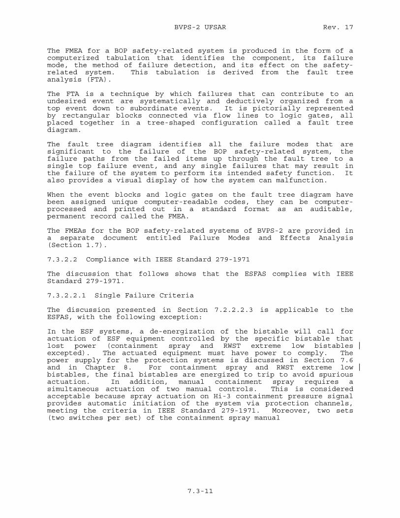
BVPS-2 UFSAR Rev. 17
7.3-11
The FMEA for a BOP safety-related system is produced in the form of a computerized tabulation that identifies the component, its failure mode, the method of failure detection, and its effect on the safety-related system. This tabulation is derived from the fault tree analysis (FTA). The FTA is a technique by which failures that can contribute to an undesired event are systematically and deductively organized from a top event down to subordinate events. It is pictorially represented by rectangular blocks connected via flow lines to logic gates, all placed together in a tree-shaped configuration called a fault tree diagram. The fault tree diagram identifies all the failure modes that are significant to the failure of the BOP safety-related system, the failure paths from the failed items up through the fault tree to a single top failure event, and any single failures that may result in the failure of the system to perform its intended safety function. It also provides a visual display of how the system can malfunction. When the event blocks and logic gates on the fault tree diagram have been assigned unique computer-readable codes, they can be computer-processed and printed out in a standard format as an auditable, permanent record called the FMEA. The FMEAs for the BOP safety-related systems of BVPS-2 are provided in a separate document entitled Failure Modes and Effects Analysis (Section 1.7). 7.3.2.2 Compliance with IEEE Standard 279-1971 The discussion that follows shows that the ESFAS complies with IEEE Standard 279-1971. 7.3.2.2.1 Single Failure Criteria The discussion presented in Section 7.2.2.2.3 is applicable to the ESFAS, with the following exception: In the ESF systems, a de-energization of the bistable will call for actuation of ESF equipment controlled by the specific bistable that lost power (containment spray and RWST extreme low bistables excepted). The actuated equipment must have power to comply. The power supply for the protection systems is discussed in Section 7.6 and in Chapter 8. For containment spray and RWST extreme low bistables, the final bistables are energized to trip to avoid spurious actuation. In addition, manual containment spray requires a simultaneous actuation of two manual controls. This is considered acceptable because spray actuation on Hi-3 containment pressure signal provides automatic initiation of the system via protection channels, meeting the criteria in IEEE Standard 279-1971. Moreover, two sets (two switches per set) of the containment spray manual
BVPS-2 UFSAR Rev. 0
7.3-12
initiation switches are provided to meet the requirements of IEEE Standard 279-1971. Also, it is possible for all ESF equipment (valves, pumps, etc) to be individually manually-actuated from the main control board. Hence, a third mode of containment spray initiation is available. The design meets the requirements of GDC 21 and 23. 7.3.2.2.2 Equipment Qualification The subject of equipment qualification is addressed in Sections 3.10 and 3.11. 7.3.2.2.3 Channel Independence The discussion presented in Section 7.2.2.2.3 is applicable. The ESF slave relay outputs from the solid state logic protection cabinets are redundant, and the actuation signals associated with each train are energized up to and including the final actuators by the separate ac power supplies which power the logic trains. 7.3.2.2.4 Control and Protection System Interaction The discussions presented in Section 7.2.2.2.3 are applicable. 7.3.2.2.5 Capability for Sensor Checks and Equipment Test and Calibration The discussions of the system testability in Section 7.2.2.2.3 are applicable to the sensors, analog circuitry, and logic trains of the ESFAS. The following discussions cover those areas in which the testing provisions differ from those for the RTS. Testing of Engineered Safety Features Actuation Systems The ESFAS are tested to provide assurance that the systems will operate as designed and will be available to function properly in the unlikely event of an accident. The testing program meets the requirements of GDC 21, 37, 40, and 43 and Regulatory Guide 1.22, as discussed in Section 7.1.2.4. The tests described herein, and further discussed in Section 6.3.4, meet the requirements on testing of the ECCS, as stated in GDC 37, except for the operation of those components that will cause an actual safety injection. The test demonstrates the performance of the full operational sequence that brings the system into operation, the transfer between normal and emergency power sources, and the operation of associated cooling water systems. The charging pumps and LHSI pumps are started and operated and their performance verified in a separate test discussed in Section 6.3.4. When the pump tests are considered in conjunction with the ECCS test, the requirements of GDC 37 on testing of the ECCS
BVPS-2 UFSAR Rev. 0
7.3-13
are met as closely as possible without causing an actual safety injection. Testing described in Sections 6.3.4, 7.2.2.2.3, and 7.3.2.2.3 provides complete periodic testability during reactor operation of all logic and components associated with the ECCS. This design meets the requirements of Regulatory Guide 1.22, as discussed in the previous sections. The program is as follows:
1. Prior to initial plant operations, ESF system tests will be conducted.
2. Subsequent to initial start-up, ESF system tests will be
conducted during each regularly scheduled refueling outage. 3. During on-line operation of the reactor, all of the ESF
analog and logic circuitry will be fully tested. In addition, essentially all of the ESF final actuators will be fully tested. The remaining few final actuators whose operation is not compatible with continued on-line plant operation will be checked by means of continuity testing.
Performance Test Acceptability Standard for Safety Injection Signal and Automatic Signal for Containment Depressurization Actuation Generation During reactor operation, the basis for ESFAS acceptability will be the successful completion of the overlapping tests performed on the initiating system and the ESFAS (Figure 7.3-3). Checks of process indications verify operability of the sensors. Analog checks and tests verify the operability of the analog circuitry from the input of these circuits through and including the logic input relays except for the input relays during the solid state logic testing. Solid state logic testing also checks the digital signal path from and including logic input relay contacts through the logic matrices and master relays and perform continuity tests on the coils of the output slave relays. Final actuator testing operates the output slave relays and verifies operability of those devices which require safeguards actuation and which can be tested without causing plant upset. A continuity check is performed on the actuators of the untestable devices. Operation of the final devices is confirmed by control board indication, and by visual observation that the appropriate pump breakers close and automatic valves have completed their travel. The basis for acceptability for the ESF interlocks will be control board indication of proper receipt of the signal upon introducing the required input at the appropriate set point.
BVPS-2 UFSAR Rev. 0
7.3-14
Frequency of Performance of Engineered Safety Features Actuation Tests During reactor operation, complete system testing (excluding sensors or those devices whose operation would cause plant upset) is performed in accordance with the Technical Specifications. Testing, including the sensors, is also performed during scheduled BVPS-2 shutdown for refueling. Engineered Safety Features Actuation Test Description The following sections describe the testing circuitry and procedures for the on-line portion of the testing program. The guidelines used in developing the circuitry and procedures are:
1. The test procedures must not involve the potential for damage to any BVPS-2 equipment,
2. The test procedures must minimize the potential for
accidental tripping of BVPS-2 systems, and 3. The provisions for on-line testing must minimize complication
of ESF actuation circuits so that their reliability is not degraded.
Description of Initiation Circuitry Several systems (listed in Section 7.3.1.1.1) comprise the total ESF system, the majority of which may be initiated by different process conditions and be reset independently of each other. The remaining functions (listed in Section 7.3.1.1.1) are initiated by a common signal (safety injection signal) which in turn may be generated by different process conditions. In addition, operation of all other vital auxiliary support systems, such as auxiliary feedwater, primary component cooling water, and service water is initiated by the safety injection signal. Each function is actuated by a logic circuit, which is duplicated for each of the two redundant trains of ESF initiation circuits. The output of each of the initiation circuits consists of a master relay, which drives slave relays for contact multiplication as required. The master and slave relays are mounted in the ESFAS cabinets, designated Train A and Train B, respectively, for the redundant counterparts. The master and slave relay circuits operate various pump and fan circuit breakers or starters, motor-operated
BVPS-2 UFSAR Rev. 17
7.3-15
valve (MOV) contactors, solenoid-operated valves, emergency diesel generator starting, etc. Analog Testing Analog testing is identical (except as noted) to that used for reactor trip circuitry and is described in Section 7.2. An exception to this is containment quench spray, which is energized to actuate two out of four and reverts to two out of three when one channel is in test. Solid State Logic Testing Except for containment spray channels, solid-state logic testing is the same as that discussed in Section 7.2. During logic testing of one train, the other train can initiate the required ESF function (Katz 1971). Katz (1971) gives additional information on solid-state logic testing. Actuator Testing At this point, testing of the initiation circuits through operation of the master relay and its contacts to the coils of the slave relays has been accomplished. Slave relays do not operate because of the reduced voltage. The ESFAS final actuation device or actuated equipment testing will be performed from the engineered safeguards test cabinets. These cabinets are normally located near the SSPS equipment. One test cabinet is provided for each of the two protection trains, Trains A and B. Each cabinet contains individual test switches necessary to actuate the slave relays. To prevent accidental actuation, test switches are of the type that must be rotated and then depressed to operate the slave relays. Assignments of contacts of the slave relays for actuation of various final devices or actuators have been made such that groups of devices or actuated equipment can be operated individually during BVPS-2 operation without causing plant upset or equipment damage. In the unlikely event that a safety injection signal is initiated during the test of the final device that is actuated by this test, the device will already be in its safeguards position. During this last procedure, close communication between the main control room operator and the operator at the test panel is required. Prior to the energizing of a slave relay, the operator in the main control room assures that plant conditions will permit operation of the equipment that is to be actuated by the relay. After the test panel operator has energized the slave relay, the main control room operator observes that all equipment has operated, as indicated by appropriate indicating lamps, monitor lamps, and annunciators on the main control board, and using a prepared checklist, records all operations. This operator then resets all devices and prepares for operation of the next slave relay-actuated equipment.
BVPS-2 UFSAR Rev. 0
7.3-16
By means of the procedure outlined previously, all ESF devices actuated by the ESFAS initiation circuits, with the exceptions noted in Section 7.1.2.4 under a discussion of Regulatory Guide 1.22, are operated by the automatic circuitry. Actuator Blocking and Continuity Test Circuits Those few final actuation devices that cannot be designed to be actuated during BVPS-2 operation (discussed in Section 7.1.2.4) have been assigned to slave relays, for which additional test circuitry has been provided to individually block actuation of a final device upon operation of the associated slave relay during testing. Operation of these slave relays, including contact operations and continuity of the electrical circuits associated with the final devices’ control, are checked in lieu of actual operation. The circuits provide for monitoring of the slave relay contacts, the devices’ control circuit cabling, control voltage, and the devices’ actuation solenoids. Interlocking prevents blocking the output from more than one output relay in a protection train at a time. Interlocking between Trains A and B is also provided to prevent continuity testing in both trains simultaneously. The redundant device associated with the protection train not under test will be available in the event protective action is required. If an accident occurs during testing, the automatic actuation circuitry will override testing as noted previously. One exception to this is that if the accident occurs while testing a slave relay whose output must be blocked, those few final actuation devices associated with this slave relay will not be overridden; however, the redundant devices in the other train would be operational and would perform the required safety function. Actuation devices to be blocked are identified in Section 7.1.2.4. The continuity test circuits for those components that cannot be actuated on-line are verified by providing indicating lights on the safeguards test racks. The typical schemes for blocking operation of selected protection function actuator circuits are shown on Figure 7.3-4 as Details A and B. The schemes operate as explained by the following and are duplicated for each safeguards train. Detail A shows the circuit for contact closure for protection function actuation. Under normal BVPS-2 operation, and equipment not under test, the test lamp DS* for the various circuits will be energized. Typical circuit path will be through the normally closed test relay contact K8* and through test lamp connections 1 to 3. Coil X2 will be capable of being energized for protection function actuation upon closure of solid-state logic output relay contact K*. Coil X2 is typical for a breaker closing auxiliary coil, motor starter master coil, coil of a solenoid valve, auxiliary relay, etc. When the contact K8* is opened to block energizing of coil X2, the white lamp is de-energized and the slave relay K* may be energized to
BVPS-2 UFSAR Rev. 0
7.3-17
perform continuity testing. This continuity testing is verified by depressing test lamp DS* and observing that the lamp lights through connection 2 (Contact K8* open) through solid-state logic output relay contact K* (now closed) and finally through actuator coil X2. Sufficient current will flow in the circuit to cause the lamp to glow but insufficient to cause the actuator coil X2 to operate. To verify operability of the blocking relay in both blocking and restoring normal service, open the blocking relay contact in series with lamp connections - the test lamp should be de-energized; close the blocking relay contact in series with the lamp connections - the test lamp should now be energized. This test verifies that the circuit is now in its normal, that is, operable condition. Detail B shows the circuit for contact opening for protection function actuation. Under normal BVPS-2 operation, and equipment not under test, the white test lamp DS*, for the various circuits will be energized, and green test lamp DS* will be de-energized. Typical circuit path for white lamp DS* will be through the normally closed solid-state logic output relay contact K* and through test lamp connections 1 to 3. Coil Y2 will be capable of being de-energized for protection function actuation upon opening of solid-state logic output relay contact K*. Coil Y2 is typical for a solenoid valve coil, auxiliary relay, etc. When the contact K8* is closed to block de-energizing of coil Y2, the green test lamp is energized and the slave relay K* may be energized to verify operation (opening of its contacts). To verify operability of the blocking relay in both blocking and restoring normal service, close the blocking relay contact to the green lamp - the green test lamp should be energized; open this blocking relay contact - the green test lamp should be de-energized, which verifies that the circuit is now in its normal (that is, operable) condition. Time Required for Testing It is estimated that analog testing can be performed at a rate of several channels per hour. Logic testing of Train A or B can be performed in less than 2 hours. Testing of actuated components (including those which can only be partially tested) will be a function of main control room operator availability. It is expected to require several shifts to accomplish these tests. During this procedure automatic actuation circuitry will override testing, except for those few devices associated with a single slave relay whose outputs must be closed and then only while blocked. It is anticipated that continuity testing associated with a blocked slave relay could take several minutes. During this time, the redundant devices in the other trains would be functional. Summary of On-Line Testing Capabilities The procedures described provide capability for checking completely from the process signal to the logic cabinets and from there to the individual pump and fan circuit breakers or starters, valve
BVPS-2 UFSAR Rev. 23
7.3-18
contactors, pilot solenoid valves, etc, including all field cabling actually used in the circuitry called upon to operate for an accident condition. For those few devices whose operation could adversely affect BVPS-2 or equipment operation, the same procedure provides for checking from the process signal to the logic rack. To check the final actuation device a continuity test of the individual control circuits is performed. The procedures require testing at various locations:
1. Analog testing and verification of bistable set points are accomplished at the process analog racks. Verification of bistable relay operation is done by the main control room status lights.
2. Logic testing through operation of the master relays and low
voltage application to slave relays is done at the logic rack test panel.
3. Testing of pumps, fans, and valves is done at a test panel
located in the vicinity of the logic racks, in combination with the main control room operator.
4. Continuity testing for those circuits that cannot be operated
is done at the same test panel mentioned in item 3. The reactor coolant pump (RCP) essential service isolation valves consist of the isolation valves for the component cooling water (CCW) and the seal water return header. For the discussion of testing limitations of these valves, refer to Section 7.1.2.4, Items 7 and 9. Containment spray system tests will be performed periodically. The pump tests will be performed with the isolation valves in the spray supply lines at the containment and spray chemical additive tank closed. The valves tests are performed with the pump stopped. During this testing, automatic actuation circuitry will override testing. Testing During Shutdown The ECCS tests will be performed in accordance with the Surveillance Frequency Control Program with the RCS isolated from the ECCS by closing the appropriate valves. A test safety injection signal will then be applied to initiate operation of active components (pumps and valves) of the ECCS. This is in compliance with GDC 37.
BVPS-2 UFSAR Rev. 0
7.3-19
7.3.2.2.6 Manual Resets and Blocking Features The manual reset feature associated with containment spray actuation is provided in the SSPS design for two basic purposes: 1) the feature permits the operator to start an interruption procedure of automatic containment in the event of false initiation of an actuate signal, and 2) although spray system performance is automatic, the reset feature enables the operator to start a manual takeover of the system to handle unexpected events which can be better dealt with by operator appraisal of changing conditions following an accident. It is most important to note that manual control of the spray system does not occur, once actuation has begun, by just resetting the associated logic devices alone. Components will seal in (latch) so that removal of the actuate signal, in itself, will neither cancel nor prevent completion of protection action, nor provide the operator with manual override of the automatic system by this single action. In order to take complete control of the system to interrupt its automatic performance, the operator must deliberately unlatch relays which have sealed in the initial actuate signals in the associated motor control center in addition to tripping the pump motor circuit breakers, if stopping the pumps is desirable or necessary. The feature of manual reset associated with containment spray does not perform bypass function. It is merely the first of several manual operations required to take control from the automatic system
BVPS-2 UFSAR Rev. 12
7.3-20
or interrupt its completion should such an action be considered necessary. In the event that the operator anticipates system actuation and erroneously concludes that it is undesirable or unnecessary and imposes a standing reset condition in one train (by operating and holding the corresponding reset switch at the time the initiate signal is transmitted), the other train will automatically carry the protective action to completion. In the event that the reset condition is imposed simultaneously in both trains at the time the initiate signals are generated, the automatic sequential completion of system action is interrupted and control will have been taken over by the operator. Manual takeover will be maintained, even though the reset switches are released, if the original initiate signal exists. Should the initiate signal then clear and return again, automatic system actuation will repeat. Note also that any time delays imposed on the system action are to be applied after the initiating signals are latched. The manual block features associated with pressurizer and steam line safety injection signals provide the operator with the means to block initiation of safety injection during BVPS-2 start-up and shutdown. These block features meet the requirements of Paragraph 4.12 of IEEE Standard 279-1971 in that automatic removal of the block occurs when plant conditions require the protection system to be functional. 7.3.2.2.7 Manual Initiation of Protective Actions (Regulatory Guide 1.62) The ESFAS agrees with Regulatory Guide 1.62 with the following clarification:
1. Manual initiation at the system level is interpreted to mean no more than three operator actions will be required to initiate at least one train, division, or channel of final actuation devices, including support systems.
2. Engineering judgement will be exercised to assure that a
minimum of operator actions are required to achieve system level manual initiation without unnecessarily jeopardizing the return to operation of the power plant. For protective actions that significantly affect return to operation, or for those protective actions that may, if inadvertently initiated, result in a less safe plant condition, operator actions on two control devices will be required.
3. Designs requiring more than two operator actions per train,
division, or channel to achieve protective action are to be limited to those actions required only in the long term and will be evaluated on a case-by-case basis.
BVPS-2 UFSAR Rev. 0
7.3-21
4. All equipment that contributes to the protective action will be initiated at the system level.
5. Switches for manual initiation will be located in the main
control room in such a manner as to permit deliberate expeditious action by the operator.
6. Equipment common to both manual and automatic initiation will
be minimized. Where manual and automatic action sequencing functions and interlocks that contribute to the protective action are common, component or channel level initiation will also be provided in the main control room.
7. Manual initiation portions of the protection system will meet
the single failure criterion. 8. Manual initiation portions of the protection system will not
impair the ability of the automatic system to meet the single failure criterion.
9. Manual initiation portions of the protective system are
designed such that once initiated, a protective action at the system level (indication of the final actuation device associated with a given protective function) goes to completion.
Having gone to completion (that is, once sufficient breakers
are closed or sufficient MOVs or other actuators are operated), a device shall only be returned to its pre-initiation status by deliberate operator action. This action shall be similar in nature for all protection systems.
This design is in compliance with Paragraph 4.16 of IEEE
Standard 279-1971. 10. In addition, manual initiation is provided to allow the
operator to take early action based on observation of plant parameters. It is not to be treated as a backup to automatic features. Operator actions will not be required to compensate for single failures.
This discussion represents an interpretation of the stated position of Regulatory Guide 1.62 with regard to philosophy and definition of terms. As such, it describes, in as much detail as required, exactly how the subject guide will be implemented. It does not take any exceptions to the stated position in the regulatory guide. The ESFAS agrees with Regulatory Guide 1.62 with the following additional clarification:
BVPS-2 UFSAR Rev. 0
7.3-22
There are three individual main steam stop valve control devices (one per loop) mounted on the main control board. Each device when actuated will isolate one of the main steam lines. In addition, there will be two sets (two momentary controls per set) of system level control devices, with either set capable of actuating all steam lines at the system level. No exception to the requirements of IEEE Standard 279-1971 has been taken in the manual initiation circuit of safety injection. Although Paragraph 4.17 of IEEE Standard 279-1971 requires that a single failure within common portions of the protective system shall not defeat the protective action by manual or automatic means, IEEE Standard 279-1971 does not specifically preclude the sharing of initiated circuitry logic between automatic and manual functions. It is true that the manual safety injection functions associated with one actuation train (for example, Train A) shares portions of the automatic initiation circuitry logic of the same logic train; however, a single failure in shared functions does not defeat the protective action of the redundant actuation train (for example, Train B). A single failure in shared functions does not defeat the protective action of the safety function. It is further noted that the sharing of the logic by manual and automatic initiation is consistent with the system level action requirements of IEEE Standard 279-1971, Paragraph 4.17, and consistent with the minimization of complexity. For the transfer of ECCS injection to the recirculation mode, refer to Sections 6.3.2.8 and 7.6.5, and Table 6.3-7. 7.3.2.3 Further Considerations 7.3.2.3.1 Instrument Air and Component Cooling In addition to the considerations given previously, a loss of reactor plant instrument air or loss of CCW to vital equipment has been considered. For the discussion concerning loss of component cooling water to the RCPs, refer to Section 7.1.2.4 under Item 7, which addresses closure of the CCW isolation valves. Loss of instrument air does not prevent the operation of the minimum systems necessary for hot standby or cold shutdown, assuming limited operator action outside the main control room, as well as operator control of the control room. Furthermore, all pneumatically-operated valves and controls will assume a safe operating position upon loss of instrument air. It is also noted that, for conservatism during the accident analysis (Chapter 15), credit is not taken for the instrument air systems nor for any control system benefit. Circuitry is not provided which directly trips the RCPs on a loss of primary CCW. The BOP design provides for alarms in the main control room whenever CCW is lost. The RCPs can run about 10 minutes after a loss of CCW. This provides adequate time for the operator to correct the problem or trip the plant if necessary.
BVPS-2 UFSAR Rev. 10
7.3-23
7.3.2.3.2 Auxiliary Feedwater System The auxiliary feedwater system (AFWS) complies with the intent of NUREG-0737 (USNRC 1980), Action Item II.E.1.2. For the description of the AFWS, refer to Section 10.4.9. The two motor-driven AFW pumps are started automatically by any one or more of the following conditions. Starting the motor-driven AFW pumps will cause the blowdown isolation and sampling isolation valves for all steam generators to close.
1. Safety injection, 2. Two out of three low-low level in any two steam generators
(from SSPS), 3. Automatic trip of main feedwater pumps, 4. AMSAC Auto Start.
The turbine-driven AFW pump is started automatically by any one or more of the following conditions. Starting the turbine driven AFW pump will cause the blowdown isolation and sampling isolation valves for all steam generators to close.
1. Safety injection, 2. Two out of three low-low level in any steam generator (from
SSPS), 3. Two out of three reactor coolant pump bus undervoltage, or 4. AMSAC Auto Start.
7.3.2.4 Summary The ESFAS detects Condition III and IV faults and generates signals which actuate the ESF. The system senses the accident condition and generates the signal actuating the protection function reliably and within a time determined by and consistent with the accident analysis in Chapter 15. Much longer times are associated with the actuation of the mechanical and fluid system equipment related with the ESF. This includes the time required for switching, bringing pumps and other equipment to speed, and the time required for them to take load. For the maximum time duration associated with ESF load sequencing, refer to Section 8.3. Operating procedures require that the complete ESFAS normally be operable. However, redundancy of system components is such that the system operability assumed for the safety analyses can still be met with certain instrumentation channels out of service. Channels that
BVPS-2 UFSAR Rev. 16
7.3-24
are out of service are to be placed in the tripped mode or bypass mode in the case of containment spray. Containment isolation satisfies the intent of NUREG-0737 (USNRC 1980), Action Item II.E.4.2, Position 4, by providing containment isolation either by a safety injection signal or by a high containment pressure signal, as shown in Table 7.3-2. 7.3.2.4.1 Loss-of-Coolant Accident Protection By analysis of LOCAs and in system tests it has been verified that except for very small coolant system breaks, which can be protected against by the charging pumps followed by an orderly shutdown, the effects of various LOCAs are reliably detected by the low pressurizer pressure signal and the ECCS is actuated in time to prevent or limit core damage. For large RCS breaks, the passive accumulators inject first because of the rapid pressure drop. This protects the reactor during the unavoidable delay associated with actuating the active ECCS phase. Hi-1 containment pressure also actuates the ECCS. Therefore, emergency core cooling actuation can be brought about by sensing this other direct consequence of a primary system break, that is, the ESFAS detects the leakage of the coolant into the containment. Section 7.3.1.2.5 gives the time between the occurrence of the low pressurizer pressure signal or the Hi-1 containment pressure signal and the generation of the actuation signal. Containment spray will provide additional emergency cooling of containment and also limit fission product release upon sensing elevated containment pressure (Hi-3) to mitigate the effects of a LOCA. The delay time between detection of the accident condition and the generation of the actuation signal for these systems is assumed to be about 1.0 second, well within the capability of the protection system equipment. However, this time is short compared to that required for start-up of the fluid systems. The analyses in Chapter 15 show that the diverse methods of detecting the accident condition and the time for generation of the signals by the protection systems are adequate to provide reliable and timely protection against the effects of loss-of-coolant. 7.3.2.4.2 Main Steam Line Break Protection The ECCS is also actuated in order to protect against an MSLB. Section 7.3.1.2.5 gives the time between occurrence of low steam line pressure, high containment pressure (for breaks in containment), or high steam line pressure rate and generation of the actuation signal. Analysis of MSLB accidents, assuming this delay for signal generation, shows that the ECCS is actuated for an MSLB in time to limit or prevent further core damage for MSLB cases.
BVPS-2 UFSAR Rev. 16
7.3-25
Additional protection against the effects of MSLB is provided by feedwater isolation, which occurs upon actuation of the ECCS. Feedwater isolation is initiated in order to prevent excessive cooldown of the reactor vessel and thus protect the RCS boundary. Supplementary protection against a MSLB accident is provided by closure of all SLIVs in order to prevent uncontrolled blowdown of all steam generators. The generation of the protection system signal is again short compared to the time to trip the fast acting SLIVs which are designed to close in less than approximately 5 seconds. In addition to actuation of the ESF, the effect of an MSLB accident also generates a signal resulting in a reactor trip on overpower ΔT or following ECCS actuation. The core reactivity is further reduced by the highly borated water injected by the ECCS. The analyses in Chapter 15 of the MSLB accidents and an evaluation of the protection system instrumentation and channel design show that the ESFAS are effective in preventing or mitigating the effects of an MSLB accident. 7.3.3 References for Section 7.3 Katz, D. N. 1971. Solid-State Logic Protection System Description. WCAP-7488-L (Proprietary) and WCAP-7672. (Instrumentation operation details apply to three loop plants; however, block diagram may not.) Mesmeringer, J. C. 1980. Failure Modes and Effects Analysis of the Engineered Safety Features Actuation System. WCAP-8760. Reid, J. B. 1973. Process Instrumentation for Westinghouse Nuclear Steam Supply System. WCAP-7913 (Instrumentation operation details apply to three loop plants; however, block diagrams may not). U.S. Nuclear Regulatory Commission 1980. Clarification of TMI Action Plan Requirements. NUREG-0737.

BVPS-2 UFSAR
Tables for Section 7.3
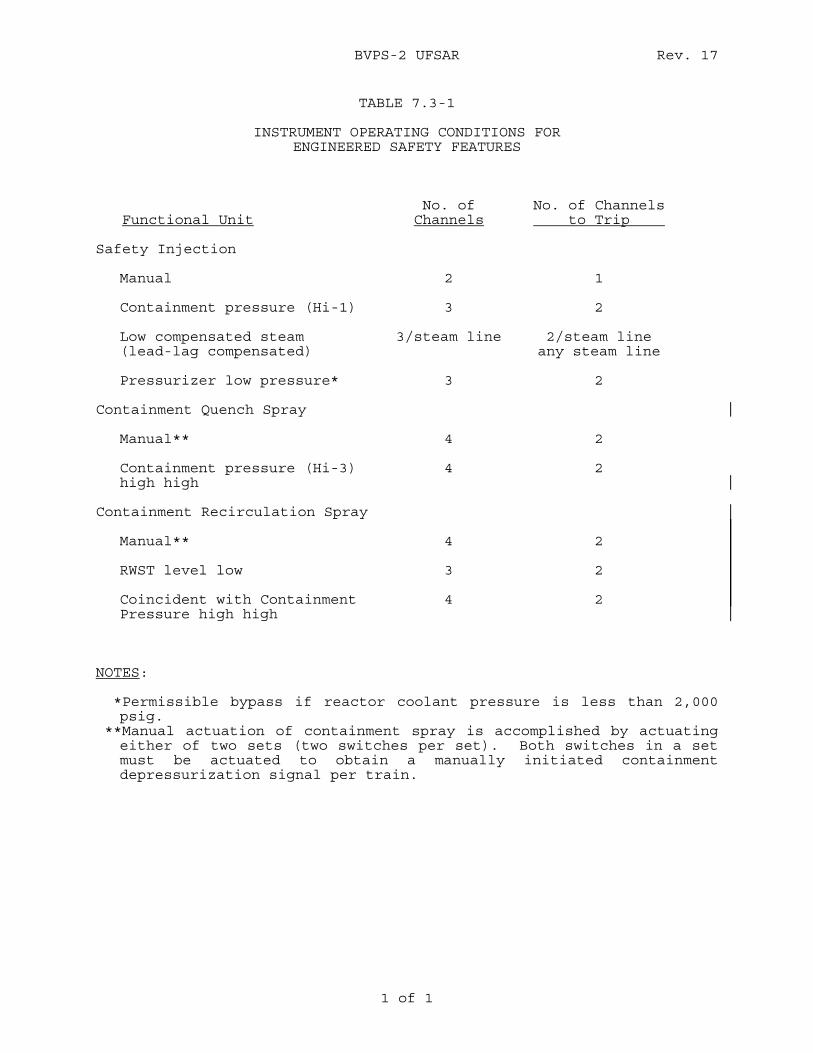
BVPS-2 UFSAR Rev. 17
1 of 1
TABLE 7.3-1
INSTRUMENT OPERATING CONDITIONS FOR ENGINEERED SAFETY FEATURES
Functional Unit
No. of Channels
No. of Channels to Trip
Safety Injection Manual
2
1
Containment pressure (Hi-1) 3 2 Low compensated steam (lead-lag compensated)
3/steam line 2/steam line any steam line
Pressurizer low pressure* 3 2 Containment Quench Spray Manual**
4
2
Containment pressure (Hi-3) 4 2 high high Containment Recirculation Spray Manual** 4 2 RWST level low 3 2 Coincident with Containment
Pressure high high 4 2
NOTES: *Permissible bypass if reactor coolant pressure is less than 2,000
psig. **Manual actuation of containment spray is accomplished by actuating
either of two sets (two switches per set). Both switches in a set must be actuated to obtain a manually initiated containment depressurization signal per train.
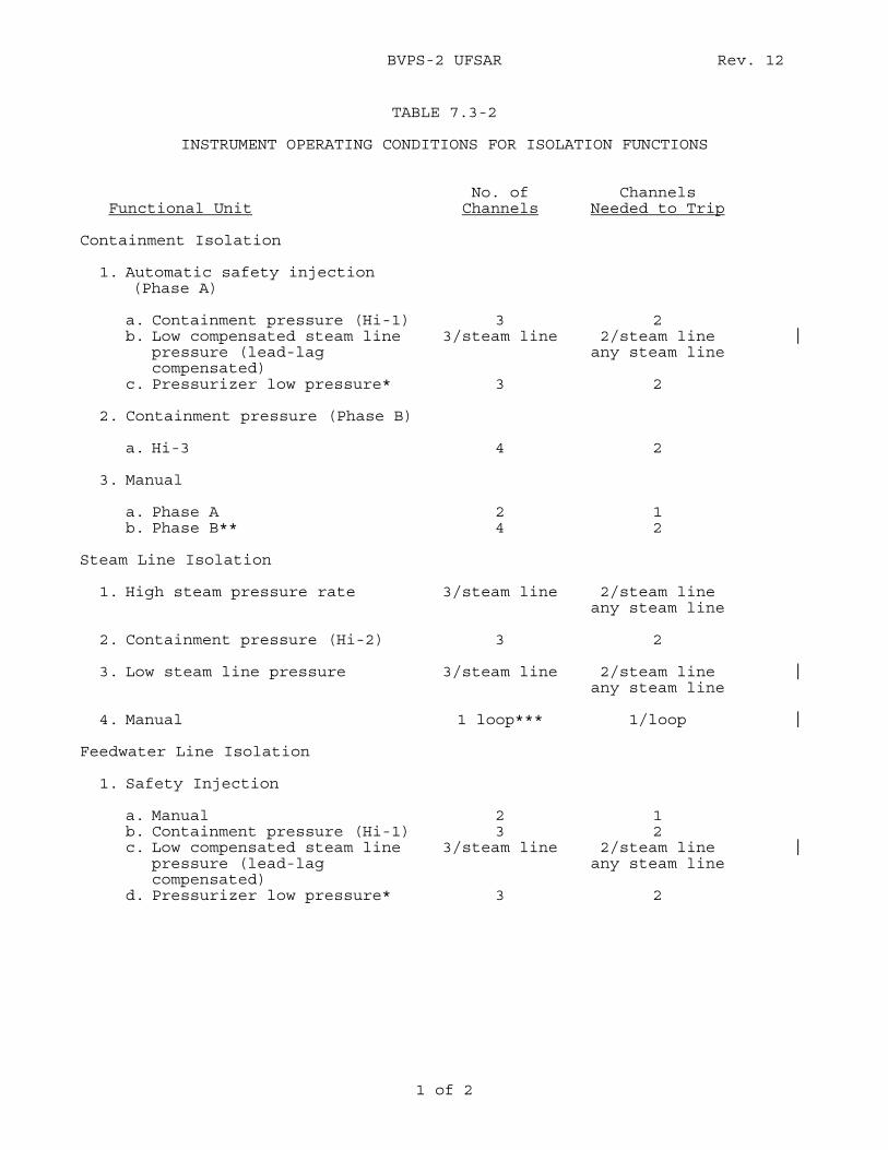
BVPS-2 UFSAR Rev. 12
1 of 2
TABLE 7.3-2
INSTRUMENT OPERATING CONDITIONS FOR ISOLATION FUNCTIONS
Functional Unit
No. of Channels
Channels Needed to Trip
Containment Isolation 1. Automatic safety injection
(Phase A) a. Containment pressure (Hi-1) b. Low compensated steam line
pressure (lead-lag compensated)
c. Pressurizer low pressure*
3
3/steam line 3
2
2/steam line any steam line
2
2. Containment pressure (Phase B) a. Hi-3
4
2
3. Manual a. Phase A b. Phase B**
2 4
1 2
Steam Line Isolation 1. High steam pressure rate 2. Containment pressure (Hi-2) 3. Low steam line pressure 4. Manual
3/steam line 3
3/steam line
1 loop***
2/steam line any steam line
2
2/steam line any steam line
1/loop
Feedwater Line Isolation 1. Safety Injection a. Manual b. Containment pressure (Hi-1) c. Low compensated steam line
pressure (lead-lag compensated)
d. Pressurizer low pressure*
2 3
3/steam line 3
1 2
2/steam line any steam line
2
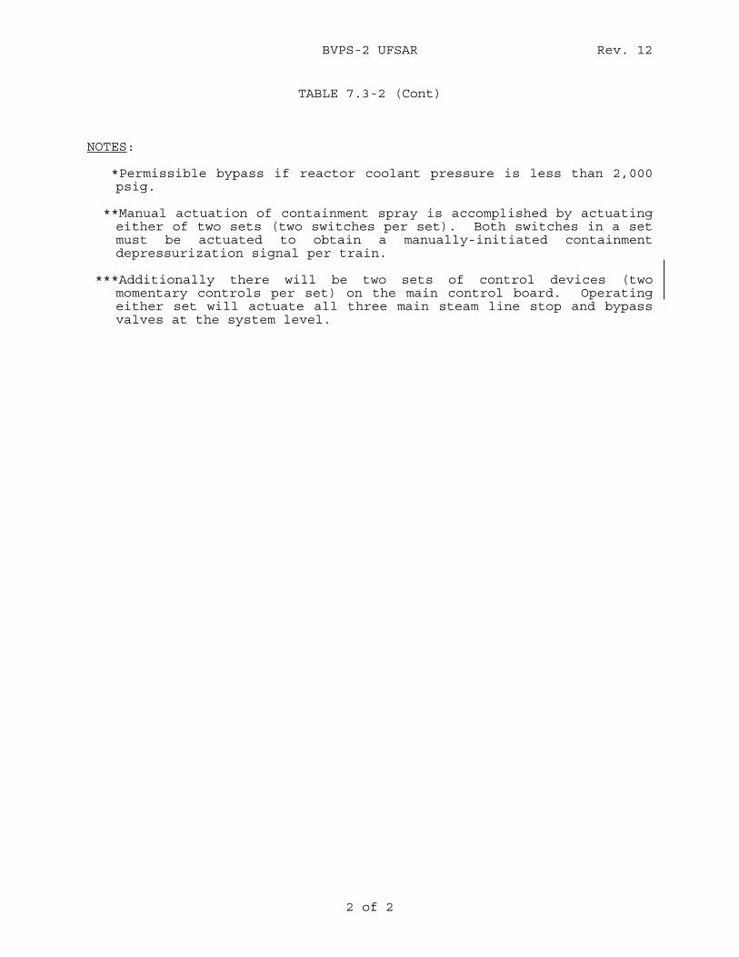
BVPS-2 UFSAR Rev. 12
2 of 2
TABLE 7.3-2 (Cont) NOTES: *Permissible bypass if reactor coolant pressure is less than 2,000
psig. **Manual actuation of containment spray is accomplished by actuating
either of two sets (two switches per set). Both switches in a set must be actuated to obtain a manually-initiated containment depressurization signal per train.
***Additionally there will be two sets of control devices (two
momentary controls per set) on the main control board. Operating either set will actuate all three main steam line stop and bypass valves at the system level.
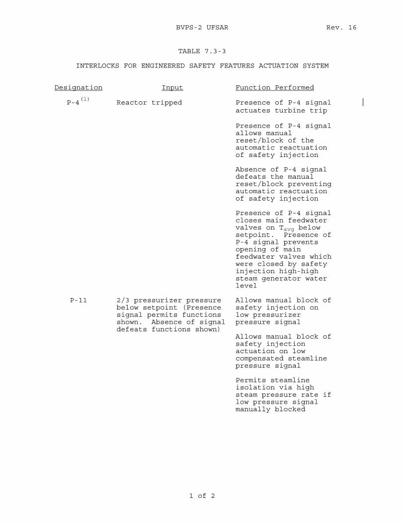
BVPS-2 UFSAR Rev. 16
1 of 2
TABLE 7.3-3
INTERLOCKS FOR ENGINEERED SAFETY FEATURES ACTUATION SYSTEM Designation Input Function Performed
P-4
(1) Reactor tripped Presence of P-4 signal
actuates turbine trip
Presence of P-4 signal allows manual reset/block of the automatic reactuation of safety injection
Absence of P-4 signal defeats the manual reset/block preventing automatic reactuation of safety injection
Presence of P-4 signal closes main feedwater valves on Tavg below setpoint. Presence of P-4 signal prevents opening of main feedwater valves which were closed by safety injection high-high steam generator water level
P-11 2/3 pressurizer pressure below setpoint (Presence signal permits functions shown. Absence of signal defeats functions shown)
Allows manual block of safety injection on low pressurizer pressure signal Allows manual block of safety injection actuation on low compensated steamline pressure signal
Permits steamline isolation via high steam pressure rate if low pressure signal manually blocked
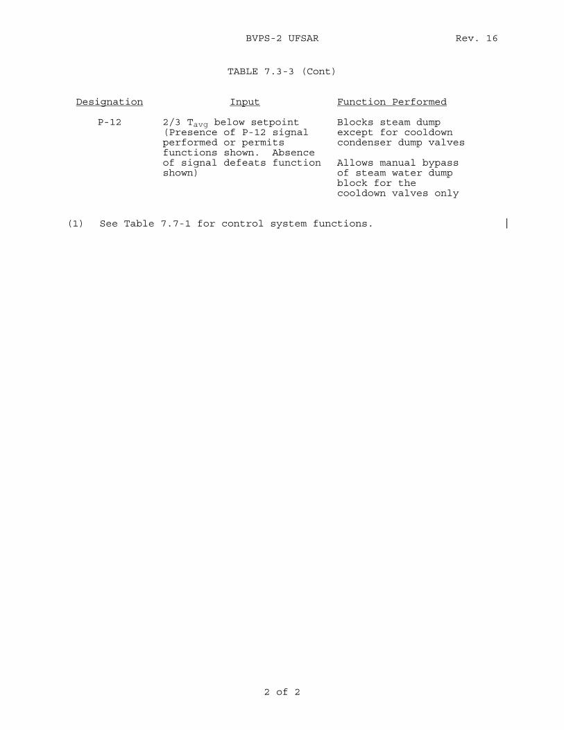
BVPS-2 UFSAR Rev. 16
2 of 2
TABLE 7.3-3 (Cont)
Designation Input Function Performed
P-12 2/3 Tavg below setpoint (Presence of P-12 signal performed or permits functions shown. Absence of signal defeats function shown)
Blocks steam dump except for cooldown condenser dump valves Allows manual bypass of steam water dump block for the cooldown valves only
(1) See Table 7.7-1 for control system functions.
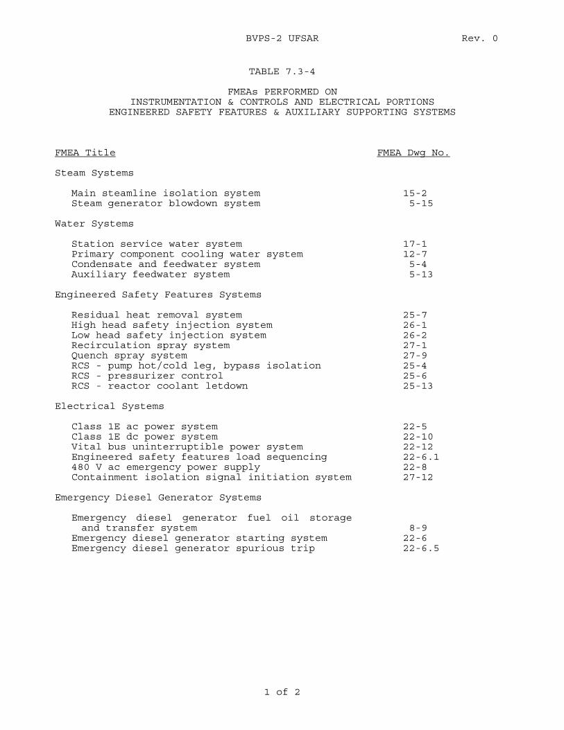
BVPS-2 UFSAR Rev. 0
1 of 2
TABLE 7.3-4
FMEAs PERFORMED ON INSTRUMENTATION & CONTROLS AND ELECTRICAL PORTIONS
ENGINEERED SAFETY FEATURES & AUXILIARY SUPPORTING SYSTEMS
FMEA Title FMEA Dwg No. Steam Systems Main steamline isolation system Steam generator blowdown system
15-2 5-15
Water Systems Station service water system Primary component cooling water system Condensate and feedwater system Auxiliary feedwater system
17-1 12-7 5-4 5-13
Engineered Safety Features Systems Residual heat removal system High head safety injection system Low head safety injection system Recirculation spray system Quench spray system RCS - pump hot/cold leg, bypass isolation RCS - pressurizer control RCS - reactor coolant letdown
25-7 26-1 26-2 27-1 27-9 25-4 25-6 25-13
Electrical Systems Class 1E ac power system Class 1E dc power system Vital bus uninterruptible power system Engineered safety features load sequencing 480 V ac emergency power supply Containment isolation signal initiation system
22-5 22-10 22-12 22-6.1 22-8 27-12
Emergency Diesel Generator Systems Emergency diesel generator fuel oil storage
and transfer system Emergency diesel generator starting system Emergency diesel generator spurious trip
8-9 22-6 22-6.5
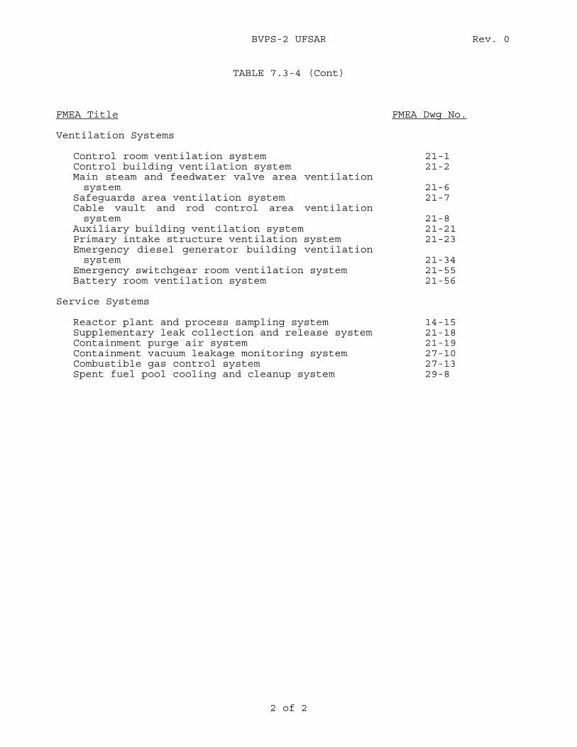
BVPS-2 UFSAR Rev. 0
2 of 2
TABLE 7.3-4 (Cont)
FMEA Title FMEA Dwg No. Ventilation Systems Control room ventilation system Control building ventilation system Main steam and feedwater valve area ventilation
system Safeguards area ventilation system Cable vault and rod control area ventilation
system Auxiliary building ventilation system Primary intake structure ventilation system Emergency diesel generator building ventilation
system Emergency switchgear room ventilation system Battery room ventilation system
21-1 21-2
21-6 21-7
21-8 21-21 21-23
21-34 21-55 21-56
Service Systems Reactor plant and process sampling system Supplementary leak collection and release system Containment purge air system Containment vacuum leakage monitoring system Combustible gas control system Spent fuel pool cooling and cleanup system
14-15 21-18 21-19 27-10 27-13 29-8
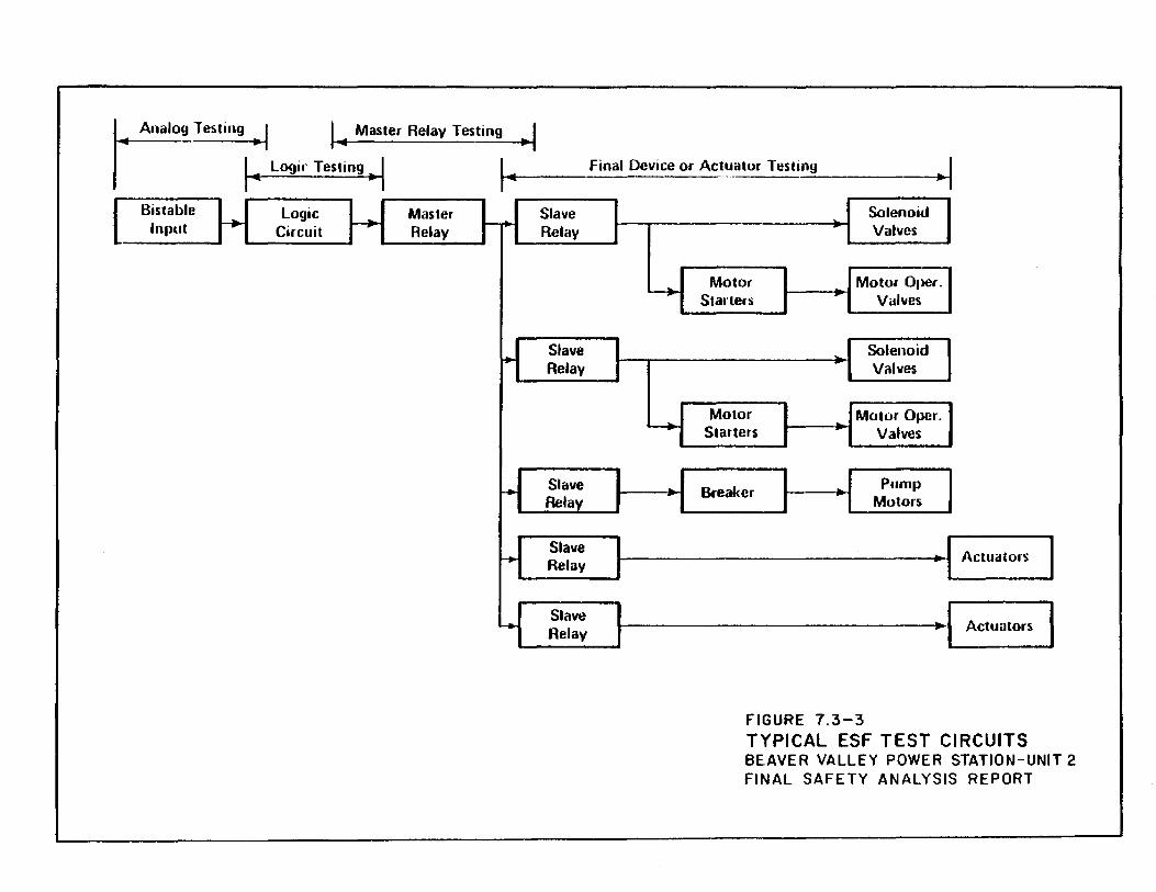
~Testing .,, J.,. Master Relay Testing •I I j... Logir Tesling •I ~ ...
Bistable Logic Master Slave Input ~ Circuit ~ Relay -· Relay
Slave .... Relay
r+ Slave Relay
Slave ..... Relay
Slave ... Relay
Final Device or Actuator Testing I _ __:::;____~
~
___...
·I Solenoid I Valves
Motor Motor 01)Cr. Starters Valves
Solenoid Valves
Motor Motor Opcr. ~· Starters Valves
·I I Breaker Pump Motors
Actuators
Actuators
FIGURE 7.3-3 TYPICAL ESF TEST CIRCUITS BEAVER VALLEY POWER STATION-UNIT 2 FINAL SAFETY ANALYSIS REPORT
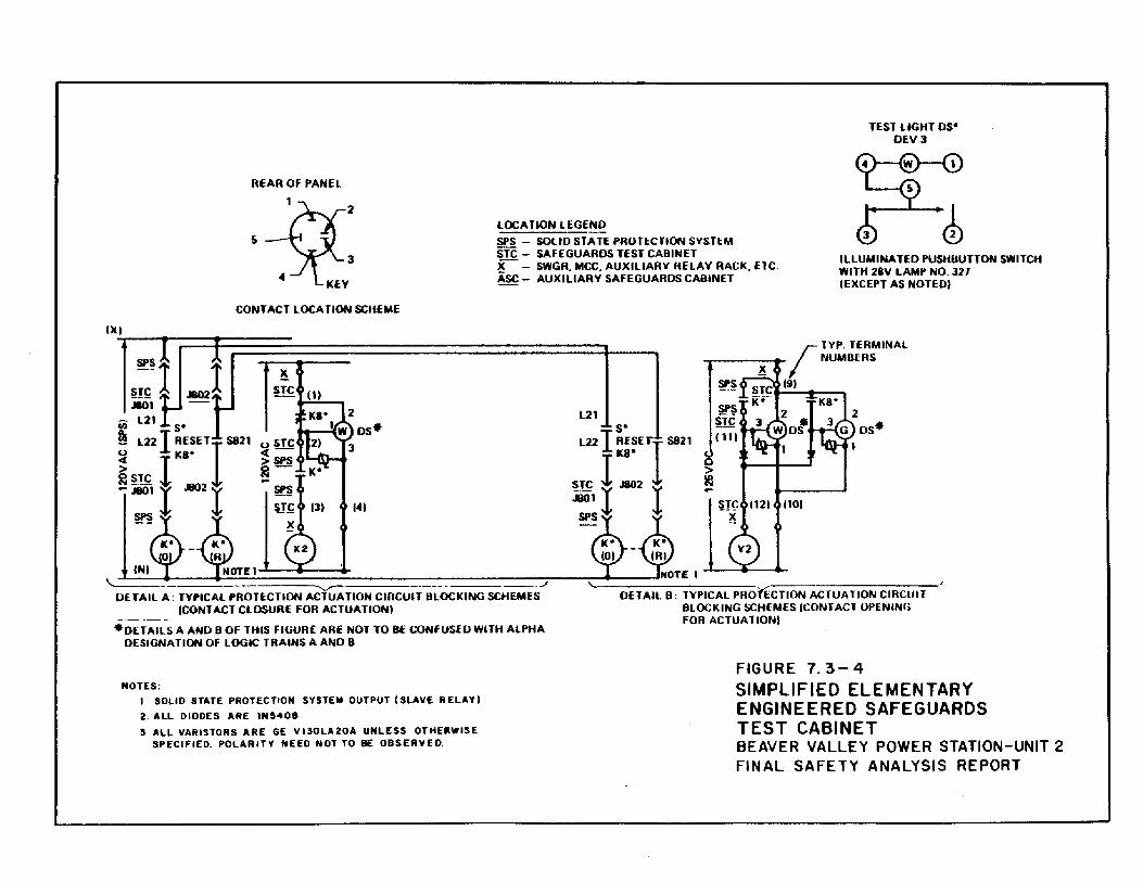
REAR OF PANEL
LOCA liON LEGEND
TEST LIGHT os• OEVJ
h' . . )[.:-: SI'S - SOLID STATE PROTECTION SYSTEM STC - SAFEGUARDS TEST CABINET ILLUMINA TEO PUSHUUTTON SWITCH
WITH 28V LAMP NO. 327 X- SWGR, MCC, AUXILIARY RELAY RACK, UC. ASC- AUXILIARY SAFEGUARDS CABINET lEXCEPT AS NOTED)
CONTACT LOCATION SCHEME
-· L21 U) s• ~ L22 I RESEll S821
~ rKa· > 0STC
~ -· I .1802 r SI'S
141
IN) \.. ----------___ .-/
Of TAIL A : TYPICAL PROTECTION AClUA liON CIRCUIT BLOCK lNG SCHEMES (CONTACT CLOSURE FOR ACTUA TIONI
• DETAILS A AND 8 OF THIS FIGURE ARE NOT TO BE CONFUSE 0 WITH AlPHA DESIGNATION OF LOGIC TRAINS A AND 8
NOTES: 1 SOLID STATE PROT EC TtON S VSTEM OUTPUT (SLAVE R ELAV I 2. ALL DIODES ARE IN~408 3. ALL VARISTORS ARE GE VI30LA20A UNLESS OTHERWISE
SPECIFIED. POLARITY NEED NOT TO BE OBSERVED.
> 1!:1 -
NOTE 1
SPS
SPS s1c (11)
~(: 1121 1101 ~
DETAIL B: TYPICAL PROnCTION ACTUATION CIRCUIT BLOCKING SCHEMES (CONTACT OPENING FOR ACTUATION)
FIGURE 7. 3-4 SIMPLIFIED ELEMENTARY ENGINEERED SAFEGUARDS TEST CABINET BEAVER VALLEY POWER STATION-UNIT 2 FINAL SAFETY ANALYSIS REPORT
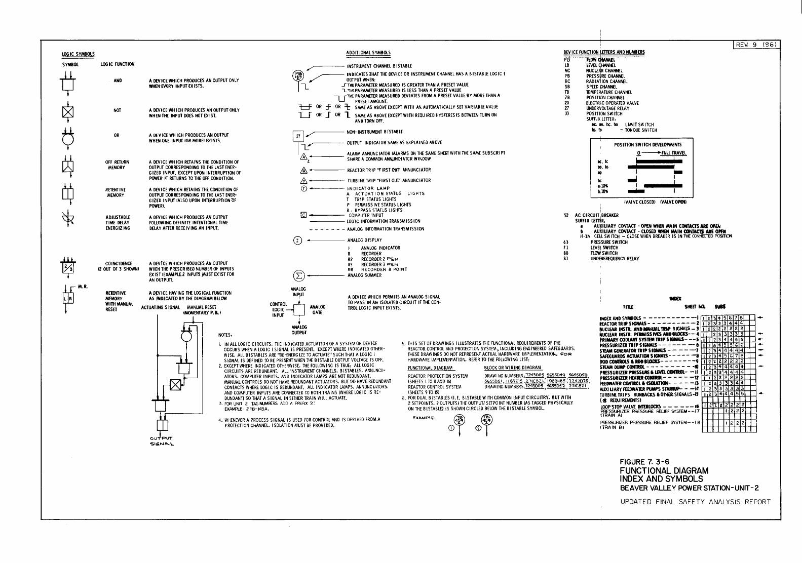
lOGIC SYMBOlS
SYMBOL LOGIC FUNCTION
AND
NOT
OR
OFF RETURN MEMORY
RETENTIVE MEMORY
AOJUSTABL£ TIME DELAY ENERGIZ lNG
COINCIDENCE l2 OUT OF 3 SHOWNI
RETINTIVE MEMORY WITH MANUAl RESET
I REV: 9 (961
A DEY ICE WHICH PRODUCES AN OUTPUT ONlY WHUt EVt:RY INPUT {X ISTS.
A DEVICE WH ICH PRODUCES AN OUTPUT ONLY WHEN THE INPUT DOES NOT {X I ST.
A )){ V ICE WH I CH PRODUCES AN OUTPUT WHEN ONE INPUT lOR MOREl t:XISTS.
A DEVICE WH ICH RETAINS THE COND ITJON OF OUT PUT CORRES POND lNG TO THE LAST ENE R-G IZED INPUT, t:XCEPT UPON INTERRUPTION OF POWER IT RETURNS TO THE OFF CON 0 I TJON.
A DEVICE WH I CH RET A I NS THE CONO IT ION OF OUTPUT COR RES PON 0 I NG TO THE LAST EN ER-G IZE 0 I N PUT lA lSO UPON INTER RU PTI ON 'Of POWERl.
A DEVICE WH ICH PRODUCES AN OUTPUT FOLLOW lNG DEFINITE INTENTIONAL TIME DELAY AFTER RECEIVING AN INPUT.
A DEVICE WHICH PROOUCES AN OUTPUT WHEN THE P R ESC R IB EO NUMBER OF INPUTS t:X IS T l EXAMPLE 2 IN PUTS .MU ST t:XlST FOR AN OUTPUT I.
A DW ICE HAV lNG 1lE lOG I CAL FUNCTION AS iMD!CATED BY THE DIAGRAM BROW
ACTUAlJNG SlGAAL MANUAL RESET lMOMENTARY P. B;. l
N01ES:
A 00 IT JONA L S Y MBOI.S
----- INSTRUMENT CHANNEL BISTABLE
'
~ IN 0 I CATES lHAT THE ()['I{C£ OR INSTRUMENT CHANNEl HAS A Ill STAB L£ LOGIC 1 Ill"' OOTPUT WHEN:
[_ .STilE PARAMETER MEASURED IS GREATER THAN A PRESET VALUE L.. THE PARAMETER MEASURED IS l£ S S THAN A PRES£T VALUE U"Tl!E PARAMETER MEASURED DEVIATES FROM A PRESET VALUE BY MORE THAN A
PRESET AMOUNT. l::::f OR :f OR =t: SAME AS AllOY£ t:XCEPT WITH AN AUTOMA HCALLY SET VAR lAB L£ IJALUE
-u- OR _f OR L SAME AS ABOVE EXCEPT WITH REOU IRED HYS TERES IS B £TWEEN TURN ON AND HJRN OFF.
-----NON-INSTRUMENT BfSTABL£
i Z7 .~~----c' OUTPUT INDICATOR SAME AS EXPLAINED ABOVE
& ----- ALARM ANNUNCIATOR !ALARMS ON THE SAME SHm WITH ThE SAME SUBSCRIPT z. SHARE A COMMON ANtiUNCiATCR WI~DOW
& ----- REACTOR TRIP ''fiRST OUT" ANNUNCIATOR
,1, ----- TURBINE TRIP ''fl RST OUT" ANNUNC lA TOR (f) INDICATOR LA'-IP
A ACTUATION STATUS LIGHTS T TRIP STATUS LIGHTS P PERMISSIVE STATUS LIGHTS B • BYPASS STATUS LIGHTS
{f)------ COMPUTER INPUT -----LOGIC INFORMATION TRAI>SMISSION - - - - - - - ANALOG INFORMAl ION TRANSMISSION
0 -----ANALOG DISPLAY
I AN"ALOG INDI CAlOR R RECORDER R2 RECORDER 2 F't.N R3 RECORDER 3 PEN
© RS RECOROER 8 POINT
L.. ----- ANALOG SUMMER
ANALOG INP1UT
CONTRO~ LOGIC INPUT
AAALOG GAll
A OEVICE WHICH Pf:RMITS AN ANALOGS I GNAt TO PASS IN AN ISOLATED C IRCUJT IF Tit: CON-TROL LOGIC INPUT EXISTS.
I
' ANALOG OUTPUT
DEVICE FUNCTION liDERS AND NUMIERS FB R.OW CWINNft . LB l[\l[~liANNE L NC NUC CHAIHL PB PRESS RE CliA~L R C RAD IAT I ON CHANNEL SB SPEEDCHAMEL TB tEMPERA lURE CHANNEL ZB POSITION CHANNEL 20 EL£CTRIC OPERATED VALVE 27 UNDERVOl TAG£ RELAY 33 POS IliON SWITCH
SUFfiX l£ffiR: IC. 10. be. bo LIM IT SWITCH ~ It - TOIIQUE SWITCH
POS IliON SW ITCH DEVELOPMENTS .Q. -fUll TRAVEL
~~:. tc bll,lo Ill be •. ms b.IOS
.. : NAIVE CtOS EDI IV Al VE OfiOO
i I
52 AC Cl RCU IT.BREAKER SUFFIX u:TJtR,
a AU~ILIARY CONTACT -OPEN WHEN M'IN CONTACTS ARE OPEN b AUXIliARY CONTACT -CLOSED WHEN !MIN CX1NrAC1S AlE OPRI H -IN CEll SW ITCH - CLOSE WHEN BREAKER I S IN THE CONNECTED POSf'TICH
63 PRESSURE SWITCH 11 L£VEl SWITCH 80 FLOW SWITCH 81 UN OERFREQUEN CY RELA '(
TITLE
I. IN ALL LOGIC CIRCUITS. THE IND ICATEO ACTUA T!ON Of A SYSTEM OR DEVICE OCCURS WHEN A LOGIC I SIGNAL IS PRESENT. EXCEP1 WHERE INDICATED OTHER-WISE.. All B ISTABL£S ARE ''DE-ENERGIZE TO ACTUATE" SUCH THAT A LOGIC I SIGNAL IS DEFINED TO BE PRESENT WHEN T\1E BISTABLE OUTPUT VOLTAGE IS OFF.
5. THIS SET OF DRAWINGS ILLUSTRATES THE FUNCTIONAL REQU lREMENTS OF THE REACTOR CONTROL AND PROTECT\ ON SYSTEM , INC LUD I NG ENG I NEE RED SAFEG UA R 0 S . THESE DRAWINGS DO NOT REPRESENT ACTUAL HARDWARE IMPL£MEN.TATION. FoR HARDWARE IMPL£11'{NTATION. REfER TO THE FOLlOWING LIST,
INOt:XANDSYMI!OlS- ----------1 1 2 3 ot 5 b 7 6 ftACTORTRIJSIGNAlS-- --------2 l 2 3 3 3 4 4 4 ~UCI.fAI lNSTI; ANIIWG.!All'IIP S IGAAlS - l I 2 2 l 2 2 2 2 IIUCLEAR INSTI. PDIMISSMSMOIUICKS--4 1 1 2 ?. 3 3 3 3 PRIMARY COOIAifl' SYStEM TIIP SlliiWS- --5 1 < 2 3 4 4 5 5 PR£SSURIZEiliiP SIGNAlS-- - --- -- 6 f I 2 3 4 5 5 G G $TEAM GENERATOR TIIP SIGNALS -- - - -7 I 2 3 't 4 4 4 4 $AFEGUARDS ACTUATIOI S IGIIAlS- - - - - -& 1 2 3 4 5 (;; 7 8 110D COIGIUit.S I ROIIIOI:KS------- -9 1 -2 2 2 2 2 2 2 STEAM DUMP COHTIOI. - - - - - - - - - ~10 1 2 3 4 4 4 4 4
OUTF"'JT SIGiNA..\...
2. EXCEPT WHERE INDICATED OTHERWISE. THE FOLLOWING IS TRUE, ALL LOGIC CIRCUITS ARE REDUNDANT. ALL INSTRUMENT CHANNELS. B I STABLES. ANNUNC 1-ATORS. COMPUTER INPUTS. AND INDICATOR LAMPS ARE NOT REDUNDANT. MANUAL CONTROLS 0 0 NOT HAVE REDUNDANT ACTUATORS. B UT DO HAVE RED UNO ANT CONTACTS WHERE LOGIC IS REDUNDANT. All INDICATOR LAMPS. ANNUNCIATORS. AND COMPUTER INPUTS ARE CONNECTED TO BOTH TRAINS \WHERE LOGIC IS RE-OUNDANTJ SO THAT A SIGNAL IN EITHER TRAIN WILL ACTUATE.
3. FOR UNIT 2 TAG NJM&RS ADD A PREFIX '2: EXAMPLE' 2PB-1<13A.
4. WHENEVER A PROCESS SIGNAL IS USED FOR CONTROL AND IS OER IV EO FROM A PROTECT ION CHANNEL. ISOLATION MUST BE PROV I OED.
FUNCTIONAL D lAG RAM BLOCK OR WI R lNG 0 lAG RAM REACTOR PROTECTION SYSTEM DRAWING NUMBERS: 1243005 %55~'1 5b55050 \SHEETS I TO SAND 16] ~,.l.!Mlli.,'tliCB'I.I: 108}HB5:~'. REACTOR CONTROl SYSTEM 0 RAW I NG NUMBERS· 1243005 %5505?. ?.11C821 \SHEETS 910151 ·---,---,---·
G. FOR DUAL B ISTABL£S (I. E. B ISTABL£ WITH COMMON INPUT CIRCUITRY. BUT WITH 2 SET POINTS. 2 OUTPUTS I THE OUTPUT/ SET POINT NUMBER lAS TAGGED PHYS \CALLY ON THE B ISTABLE/1 5 SHOWN C IRCL£0 BELOW THE B I STABL£ SYMBOL
EXAMPle
I'RESSURIZEI NESSUREI LliiELCONliOL- -If I 2 '3 3 4 4 4 4 pRESSURIZO H£A10 CCIIGIOl- - - - - -12 1 1 2 2 2 2 2 2 fnDWAmt COHTIOL IISCIATICII- - - - -I) I 2 3 3 3 3 4 4 4UXI UARY FEEDWAlER PUMPS STAIJWI- - -lot 1 2 '3 3 3 3 3 3 TURBI~ TRIPS RUNBACKS & OlliUtSIGNA L.S -15 I 2 3 ~ 4 4 5 5 ( i REQU I REMENTSl LOOP STOP VALVE I~---- --16 l 2~ t 2 2 2 2 rm~11ZER PRESSURE RELIEF SVSTEM--17 l 2 2 2
F!iESSURlZER PRESSURE RELIEF SVSTEM- -I 8 1 2 2 2 !TRAIN 81 H-++-H!::.+==-1-=-1-1-1
FIGURE 7. 3-6 FUNCTIONAL DIAGRAM INDEX AND SYMBOLS
--
BEAVER VALLEY PCNIER STATION-UNIT-2
UPDATED FINAL SAFETY ANALYSIS REPORT
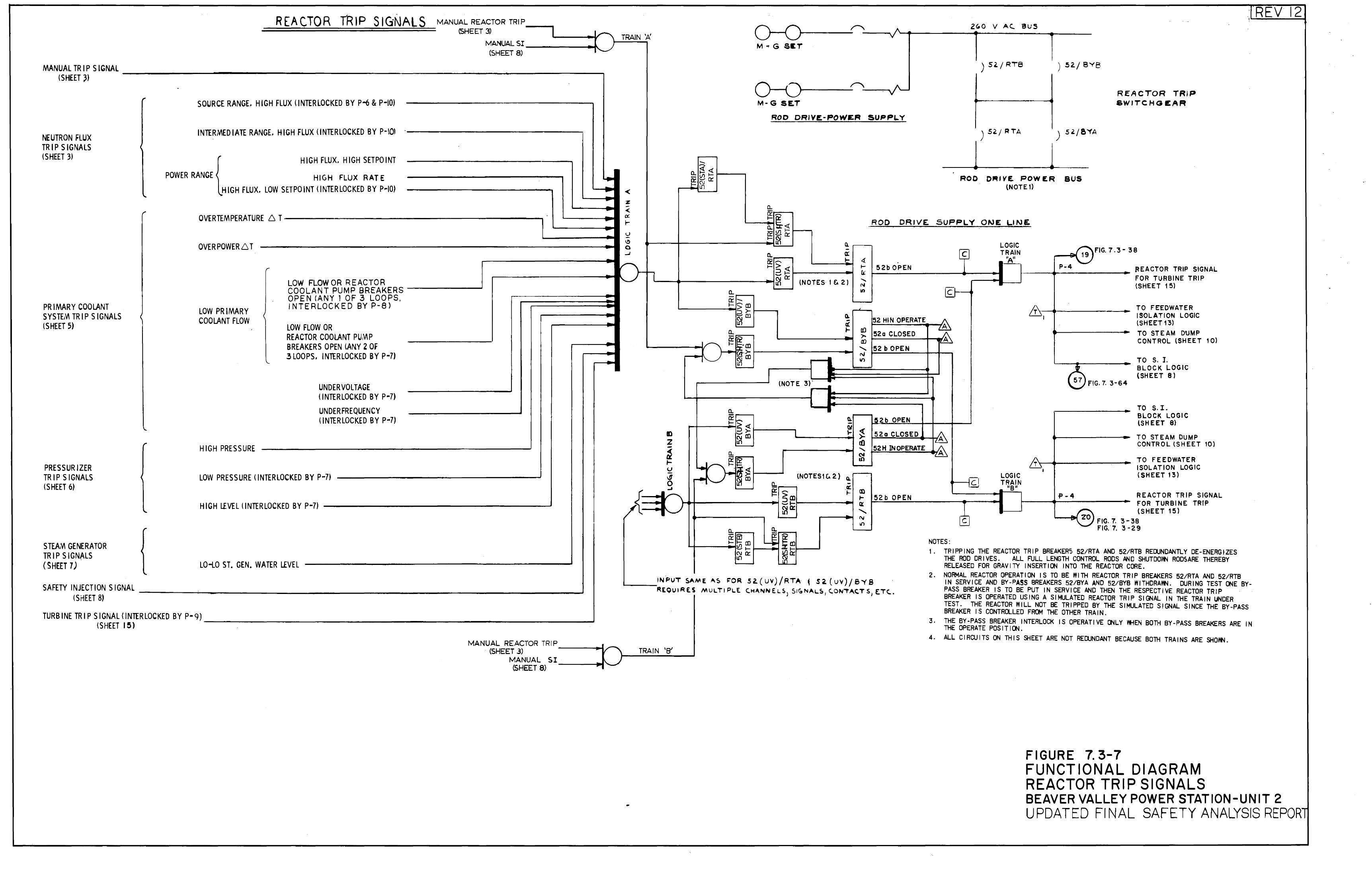
REACTOR ffi IP s IG·NALS MANUAL REACTOR TRIP_...., (SHEET 3)
MANUALSI----------~~ (SHEET 8)
MANUAL TRIPS IGNAL -----------------------------~------------, (SHEET~~
NEUTRON FLUX TRIP SIGNALS (SHEET 3)
,. SOURCE RANGE. HIGH FLUX (INTERLOCKED BY P-6 & P-10)
INTERMEDIATE RANGE. HIGH FLUX (INTERLOCKED BY P-101 ·----------------;
,. HIGH FLUX. HIGH SETPOINT
TRAIN 't>:
;J. POWER RANGE HIGH FLUX RATE HIGH FLUX. LOW SETPOINT <INTERLOCKED BY P~IO)
... "'
PRIMARY COOLANT SYSTE,'A TRIP SIGNALS (SHEET 5)
OVERTEMPERATURE 6 T-----------------------,
OVERPOWER6 T
LOW PRIMARY COOLANT FLOW
HIGH PRESSURE
LOW FLOW OR REACTOR COOLANT PUMP BREAKERS _____ ___,J OPEN fANY I OF 3 LOOPS, INTERLOCKED BY P-8)
LOW FLOW OR REACTOR COOLANT PU,'A P BREAKERS OPEN lANY 2 OF 3 LOOPS. INTERLOCKED BY P-71
UNDER VOLTAGE (INTERLOCKED BY P-7)
UNDER FREQUENCY (INTER LOCKED BY P-7)
LOW PRESSURE <INTERLOCKED BY P~7)
% -< ex: - 1-.._, -\!) 0 ~
(\ ~ L
PRESSURIZER TRIP SIGNALS (SHEET 6)
.. HIGH LEVEL (INTERLOCKED BY P-7) --------------------' {----STEAM GENERATOR TRIP SIGNALS (SHEET 7)
r
... LO-LO ST. GEN. WATER LEVEL
SAffniNJECTIONSIGNAL ____ ~~~---------------~--~--------~-~ (SHEET 8)
TURBINETRIPSIGNAL(INTERLOCKED BY P-9)~--~-~~--~---~---~~--~-~~~---~-___,J (SHEET 15)
MANUAL REACTOR TRIP ___ ___,~J..---...
ID z -~ .... u ~ 0 ...
a. c:t: f-
(SHEET 3) r \ TRAIN 'B' MANUAL S I 1\ 1--___;,...;;....;_;,_...;;._ _ __.
(SHEET 8)
-~<t o./l~ ~a:
~
a. -cr -~ $1Il :::>>-~[])
~ a. ~~-([)
~ ~->-C\IID I{)
-"" r-------- ---~
M., G Slli
r---------~--~.~~ M- G SE.T
ROD DRIVE-POWER SUPPLY
a. c:t: ~
ZG.O V AC. BUS
j ) 5~/ ~TA
l ROD D,..IVE POWER
(NOTE 1)
) 52./ 8YB
) S'/!YA
BUS
REACTOR TRIP &WITCHGEAFt
; '-'-R;..=E....;_V --'-1 =-t2
~
~~ ROD DRIVE SUPPLV 0"->E LINE. a. ~
a. cr 1-
.!lla: f?i
~ > :::>~ (ijc:t: I{) (NOTES 1 e;. 2)
CL -I( ... -"
~ . f- 52b OPEN ex: ......
"' II)
5:2 HIN OPERATE
~ 52a CLOSED (I)
......_ 52 b OPEN N Ill
c LOGIC TRAIN
'Au FIG. 7. 3- 3 8
r--lil'\ 19
~---~P __ -4 _________ ~EACTOR TRIP SIGNAL. r --f-__j FOR TURBINE TRIP
(SHEET 15) c-•t--_.
&-----+-----'
...!.
TO FEEDWATER ISOLATION LOGIC (SHEET 13) TO STEAM DUMP CONTROL lSH EE T 1 O)
TO S. I. BLOCK LOGIC (SHEET 8)
(NOTE 3)'
ll::======~ ~FIG. 7. 3-64
~ -Ill ~ 1-
cO ' <'I Lll
(NOTES! C. 2) Q. -~ a)
I-tt .......
.----~ rv 11'1
l~2b OPEN
52a CLOSED
52H INOPERAT.E
52b OPEN
c
NOTES:
LOGIC TRAIN
usn
TO S. I. BLOCK LOGIC (SHEET 8)
TO STEAM DUMP CONTROL (SHEET 10)
/r'r~.-+-----•
TO FEEDWATER ISOLATION LOGIC (SHEET 13)
f'-4
1----e-f zo
REACTOR TRIP SIGNAL. FOR TURBINE TRIP (SHEET 15)
FIG. 7. 3-38 FIG.7.3-29
1. TRIPPING THE REACTOR TRIP BREAKER5 52/RTA AND 52/RTB REDUNDANTLY OE-ENERGfZES THE ROD DRIVES. ALL. FULL LENGTH CONTROL. RODS .bN D SHUTDOI't4 ROD$ ARE THEREBY RELEASED FOR GRAVITY INSERTION INTO THE REACTOR CORE.
2. NORMAL. REACTOR OPERATION IS TO BE WITH REACTOR TRIP BREAKERS 52/RTA AND 52/RTB IN SERVICE AND BY-PASS BREAKERS 52/BYA AND 52/BYB WITHDRAWN. DURING TEST ONE BY-PASS BREAKER IS TO BE PUT IN SERVICE AND THEN THE RESPECTIVE REACTOR TRIP BREAKER IS OPERATED USING A SIMULATED REACTOR TRIP SIGNAL. IN THE TRAIN UNDER TEST. THE REACTOR WILL. NOT BE TRIPPED BY THE SIMULATED SIGNAL SINCE THE BY-PASS BREAKER IS CONTROLLED FROM THE OTHER TRAIN.
3. THE BY-PASS BREAKER INTERLOCK IS OPERATIVE ONLY WHEN BOTH BY-PASS BREAKERS ARE IN THE OPERATE POSITION.
4. ALL. CIRCUITS ON THIS SHEET ARE NOT REDUNDANT BECAUSE BOTH TRAINS ARE SHOI't4.
FIGURE 7. 3-7 FUNCTIONAL DIAGRAM REACTOR TRIP SIGNALS BEAVER VALLEY POWER STATION-UNIT 2 UPDATED FINAL SAFETY ANALYSIS REPORl
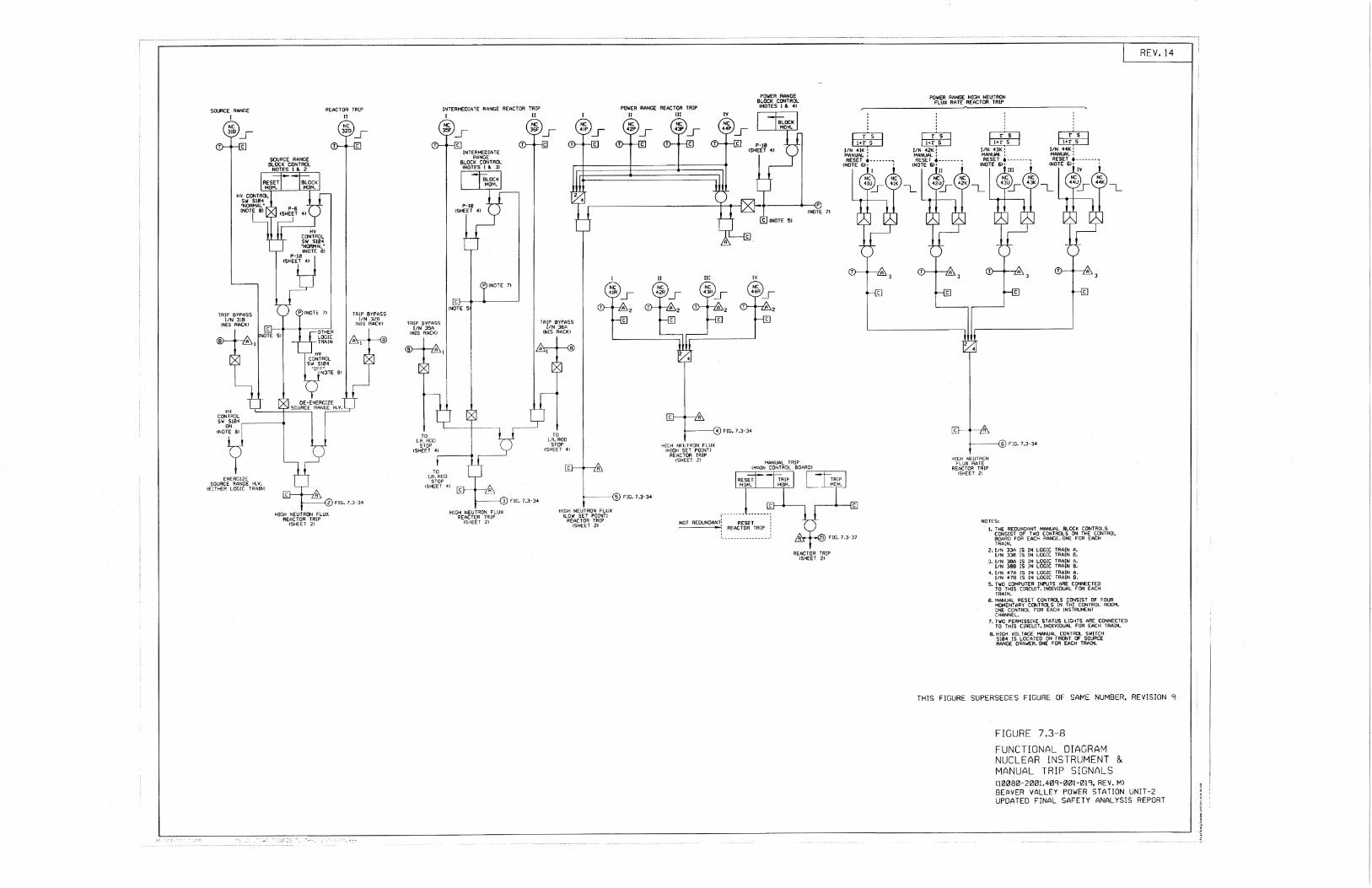
SOURCE RANGE I
REACTOR TRIP II
HIGH NEUTRON FLUX REACTOR TRIP
!SHEET 2l
INTERMEDIATE RANGE REACTOR TRIP I II
TO !.A. ROO
STOP !SHEET 4l
~--_.
TO I.R- ROO
STOP !SHEET 41
HIGH NEUTRON FLUX REACTOR TRIP
<SHEET 2)
TO I.R. ROO
STOP !SHEET 4l
HIGH NEUTRON FLUX !LOW SET POINTJ
REACTOR TRIP !SHEET 21
POWER RANGE REACTOR TRIP ll Ill
HIGH NEUTRON FLUX: tHIGH SET POINT!
REACTOR TRIP !SHEET 2l
NOT REDUNDANT!
REACTOR TRIP <SHEET 21
c::L:D ~
I/N 41K' MANUAL : RESET ·--------.
!NOTE 61' I
I
POWER RANGE HIGH NEUTRON fLUX RATE REACTOR TRIP
r-rs-J ~
I/N 43K • MANUAL : RESET ·-------,
!NOTE 6)• • Ill
---------@)FIG. 7.3·34
HIGH NEUTRON FLUX RATE
REACTOR TRIP !SHEET 2J
NOTES: 1. THE REDUNDANT MANUAL BLOCK CONTROLS
CONSIST OF TWO CONTROLS ON THE CONTROL BOARD FOR EACH RANGE. ONE FOR EACH TRAIN.
2. 1/N 33A IS IN LOGIC TRAIN A. l/N 338 IS IN LOGIC TRAIN B.
3. J/N 38A IS lN LOGIC TRAIN A. liN 388 IS IN LOGIC TRAIN B.
4. l/N 47A IS IN LOGIC TRAIN A, f/N 4 78 IS IN LOGIC TRAIN 8.
5. TWO COMPUTER INPUTS ARE CONNECTED TO THIS CIRCUIT. INOIVlOUAL FOR EACH TRAIN.
6- MANUAL RESET CONTROLS CONSIST OF FOUR MOMENTARY CONTROLS IN THE CONTROL ROOM. ONE CONTROL FOR EACH INSTRUMENT CHANNEL.
7. TWO PERMISSIVE STATUS LIGHTS ARE CONNECTED TO THIS CIRCUIT. INOIVlDUAL FOR EACH TRAIN.
8. HIGH VOLTAGE MANUAL CONTROL SWITCH 5104 IS LOCATED ON FRONT OF SOURCE RANGE DRAWER. ONE F=OR EACH TRAIN.
THIS FIGURE SUPERSEDES FIGURE OF SAME NUMBER. REVISION 9
FIGURE 7.3-8
FUNCTIONAL DIAGRAM NUCLEAR INSTRUMENT & MANUAL TRIP SIGNALS Olillil8IZI-200l.409-00HH 9, REV. M) BEAVER VALLEY POWER STATION UNIT-2 UPDATED FINAL SAFETY ANALYSIS REPORT
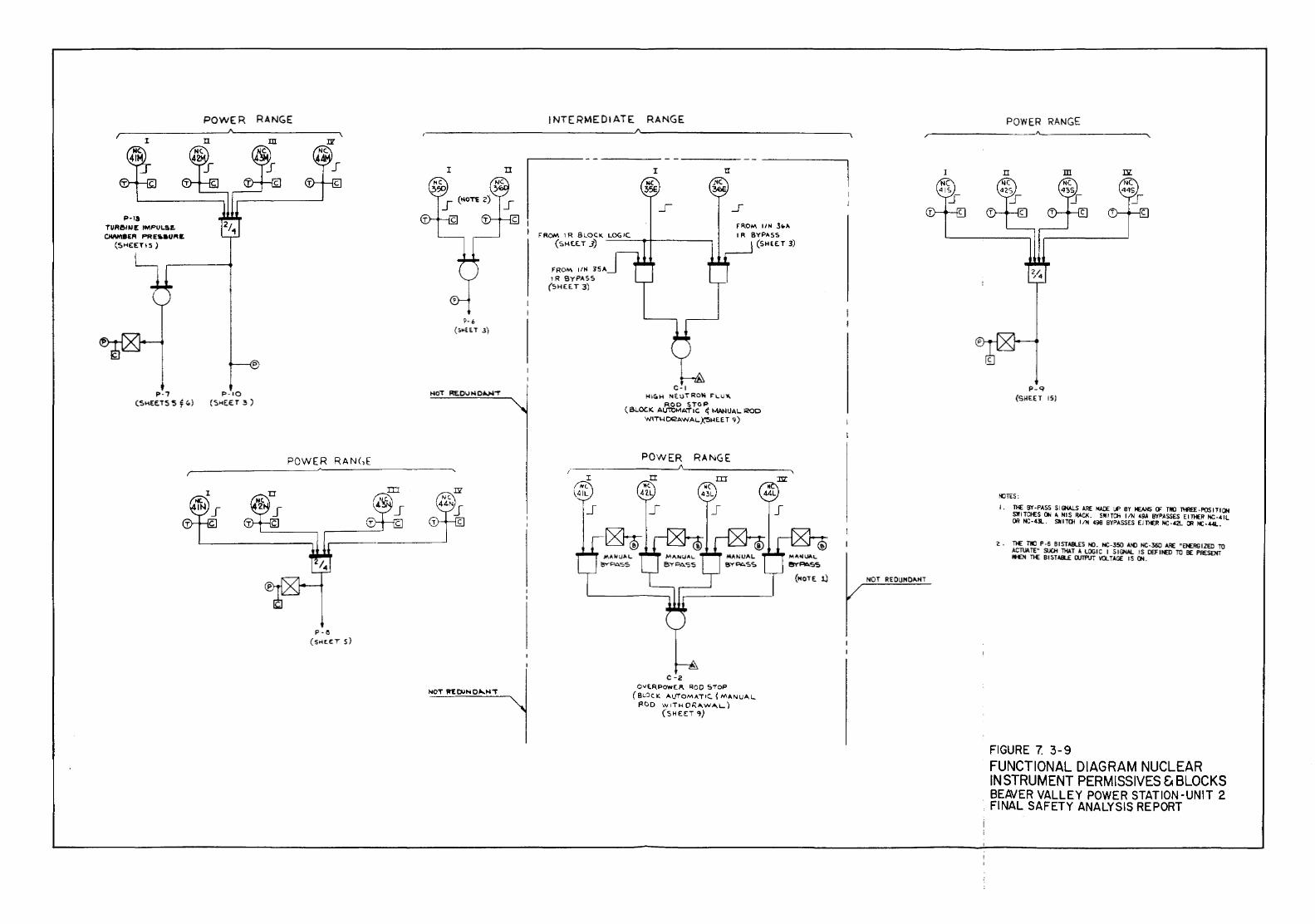
POWER RANGE
I
P-Ia TUReiNE IMPULS!. CIW'IBER PRE-01'1~
(SHE:ET!5)
n
P·7 P·IO (SHEETS'S ~ '-) (SHE.£ T 3 )
m
POWER RANC,E
P·ll (51-!E.ET 5)
I
~- 6 (sMH.T J)
t-101 RE.OUt-IO~"T
n
INTERMEDIATE RANGE
FROM liN 35,.J IR BYPASS
(St-IEET 3)
I
C-1
fi'I.OM liN 3""' SYP"'SS
(SHEET 3)
1-!ICOH NE uTROioi l'l .. u.._ ROO STOP
(&.OCK A\J1't)MA1"1C ~ MAN!JA\..ICOD WITI-IDI2AWA\..~HEET '7)
POWER RANGE
c -2 OVE.RPOWE/1. '100 STOP
(BLOCK A\JTOMATIC.l MANUAl.. POD v.; ITH OR"W"'L)
(SHE<:T ~)
POWER RANGE /----------------
I
NOT REOlJNOANT
n m m.
f .---------
p_q (SHEET 15)
~TES:
I • 1}£ BY ·PASS S I GI'W.S ARE lolAOE Lf' BY ~ CF TliO TtllEE- F'OS 1 T 1 C»1 Sl!ITCI£S ON A N I S RACI< . SW I TO! liN ~9.1 BYPASSES E ln£R NC. ~ 1 L OR NC-0... Sill~ liN 49!! BYPASSES Em£R NC-42l OR NC-441..
Z . Tl£ TWO P ·S BISTASLES ~- NC-350 ~ NC-360 4RE "ENERG IZEC ro ACTUI. TE" 5UC.H TH.t. T A LOG I C I 5 I GNAL IS OEF I t£D Ttl BE PRESENT I'I£N Tl£ B I STABLE WT!'UT VOLTAGE IS Ctl.
FIGURE 7. 3-9 FUNCTIONAL DIAGRAM NUCLEAR INSTRUMENT PER MISSIVES ~BLOCKS BEAVER VALLEY POWER STATION-UNIT 2 FINAL SAFETY ANALYSIS REPORT
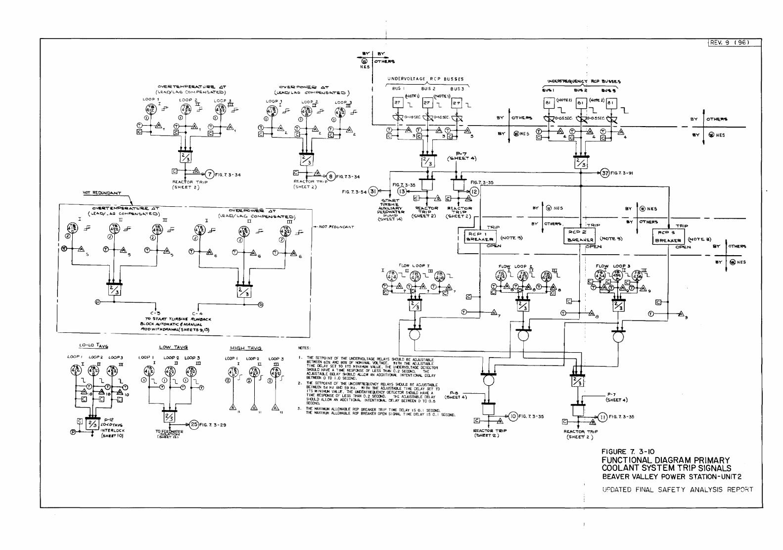
UNDERVOLTAGE RCP BUSSES
OVEI'i!. TI:M'i"E<Uo.."T L.lli!'a. .O,T (LEA.q'LA.u COM PE.N"'A.TE.C)
OVC.Q PoNE.~ AT
(L~ LA.G> COH<>i.'-ISO....TC.C) BUS I 8 us 3
lOOP 2. li ~
R.EI\C. OR TRIP (SHE.ET 2)
Q\flf.lli.TE MP!ilii ..... TU ...... .O.T ( I..EA.C/. I>.G C.oMP&.NSA.."TE.O)
5
n m I
c-~ c- 4-7n STA.CT TUR81Nfi. RUNSACK.
ISL OCK AVTOI>t AT 1C ~ N!.VJU"''-ROO W/THORAw>.l( S MEETS 9, l!i) -------
LOW TAV~
LOOP/ LOOP~ L00P3 LOOP I LOOP 7. LOOP~
1 .II m
FIG. 7. 3-34
OVI!JC..<=CW~~ AT (LI<. A.D/ LA..<O, Co MPe.N'io ..... 'Te.C)
II m
I
-+-N07' ,.EDLJNDAN7'
'<>T"'-'ii!.T T~Sio.\E
AIJ)c 11..1 A.RY ~'U)W .. "Ti.~
P\JMP (~H'E.E.o ·,4)
7
__ _j ~IGH TAVG
LOOP I LOOP 2 LOOP 3 I D m
~TES;
I . THE SET PO I NT OF THE UNDERI'OL TAGE RELAYS ~Oll_O BE ADJUST ABLE BETWEEN 60% AND 80% OF N(]oil NAL \Q.. TAEE. Ill TH THE ADJUSTABLE T I ME !lELA Y SET TO ITS M IN lloUI VALUE , THE U.'IJERVOL TAGE DETECTOR SHJLJ._O HAVE A T I ME RESP~SE OF LESS THAN 0 • 2 SEOJND. THE AD.AJS TABLE DB._AY SH\U..O ALLOW AN ADD I TIO:JNAL I N TENT I DNAL DELAY BETWEEN 0 TO I . 0 SECOND.
2 • TIE SET PO I NT OF THE UN DERFREWENCY RELAYS SHJULO BE A[;JIJS TABLE BETIIEEN 54 Hz AND 59 Hz . Ill TH THE ADJUST ABLE T I ME DELAY SET TO I TS M I ~ I MUM VALUE, THE UNDERFREQJENCY DETECTOR SfO.J..D HAVE A Fl-8 Tl ME RESPONSE OF LESS THAN 0 . 2 SE~D. THE ADJUSTABLE DELAY ( ~ E'E.T 4) SHOULD ALLOW AN ADD I Tl ~AL I NTENT I ONAL DELAY BE TilE EN 0 TO 0 . 5 SEDOND.
3. THE MAXIIoUI ALLOWABLE RCP BREAKER TRIP Tl ME DELAY IS 0. I SEDOND. TIE IIAX I Mllol ALLOWABLE RO" BREAKER OPEN S I Q-IAL T I ME DELAY I S 0 • I SECOND.
c
BY O"T~E.~
lii:EACTOii Tli!IP (~I!'CT'Z.)
BY @ NES
R£1\C.oO~ TRIP (SHEer 2.)
REV. 9 f 961
BY O"THa~
BY €il NES
BY @ NES
FIGURE 7. 3-10 FUNCTIONAL DIAGRAM PRIMARY COOLANT SYSTEM TRIP SIGNALS BEAVER VALLEY POWER STATION-UNIT2
lPOATEO FINAL SAFETY ANALYSIS REPQ;T
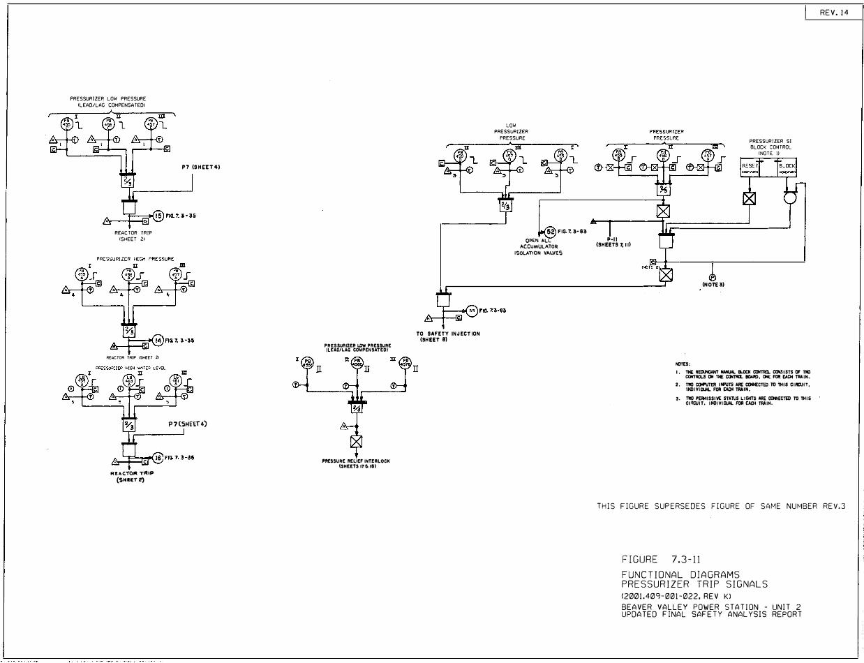
PRESSURIZER LOW PRESSURE
<LEAD/LAG COMPENSATEDl
REACTOR TRIP
<SHEET 2>
REACTOR TRIP tSHEET 2>
REACTOl'I TRIP (SHHTi?)
P7 (SHEET4)
P7(SHcET4)
I PB
II
PRESSURIZER LOW PRESSURE l\ .. EAD/LAG COMPENSATED)
PRESSURE REllEF IHT!RlOCK ISHEETS 171> 18)
TO SAFETY INJECTION (SHEET 81
II
LOW
PRESSURIZER
PRESSURE
52 FIG. 7. 3·83
OPE� ALL P·ll
ACCUMULATOR (SHEETS 7, 11) ISOLATION VALVES
(NOTE3)
NOTES:
PRESSURIZER SI
BLOCK CONTROL
<NOTE Jl
I. 11€ RECUICAHT NAHUAL llLOCK CCHTRO.. COISISTS f;, TllO ClllTRDLS ON T>E CONTill. l!OMD, ONE FOR EACH TAAIN.
2. T1IO IXM'l/TER li.llTS ARE COINECTED TD THIS CIRCUIT, INDIYIDUIL FOR EAQI TRAIN.
'· TllO PERMISSIVE STATUS LIGKTS ARE �ECTED TD THIS Cl'ICUIT, INOIYllllJI. FOR EAQi TRAIN.
REV. 14
THIS FIGURE SUPERSEDES FIGURE OF SAME NUMBER REV.3
FIGURE 7.3-11
FUNCTIONAL DIAGRAMS PRESSURIZER TRIP SIGNALS
(2001.409-001-022, REV Kl
BEAVER VALLEY POWER STATION - UNIT 2 UPDATED FINAL SAFETY ANALYSIS REPORT
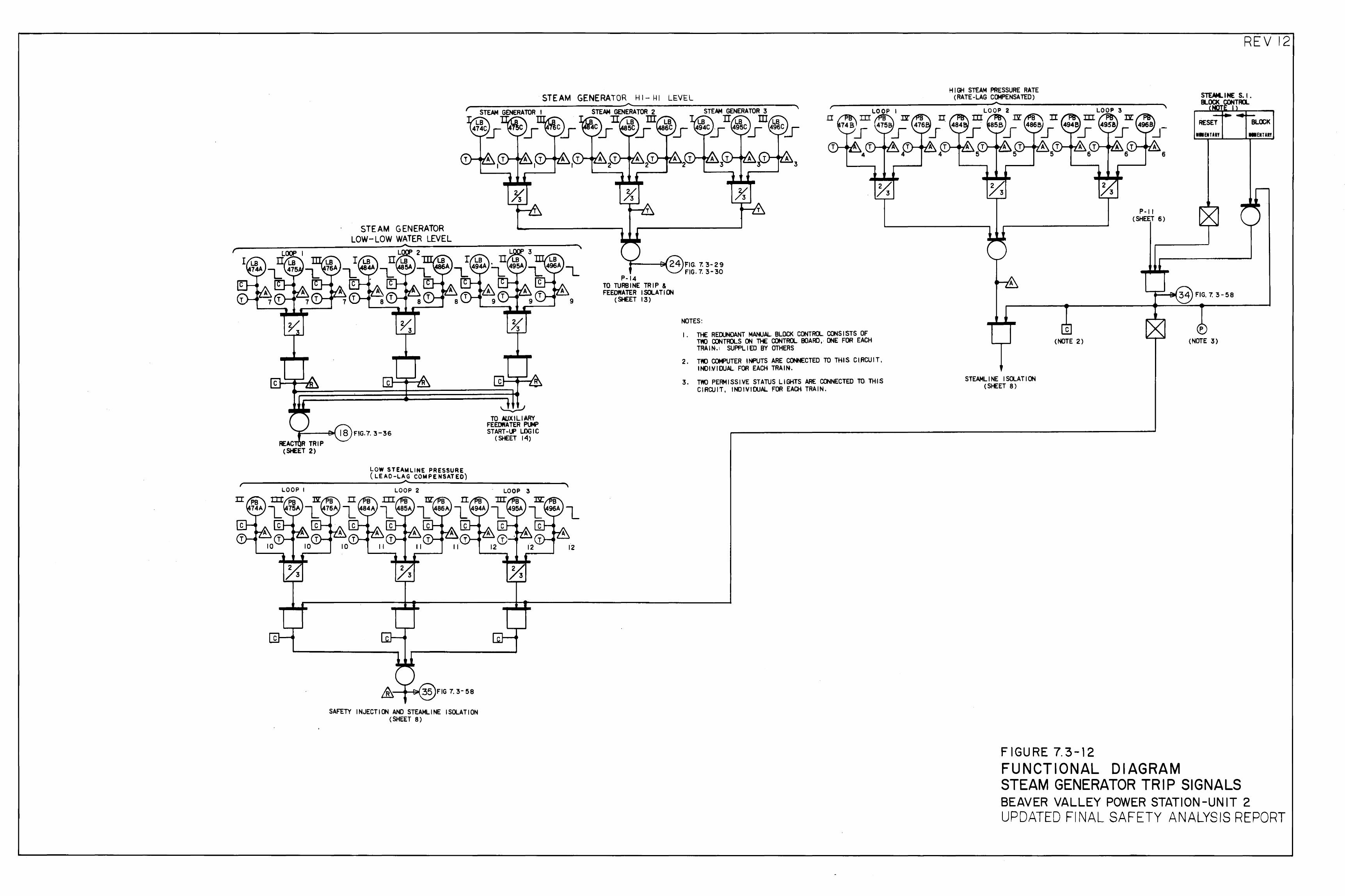
STEAM GENERATOR HI- f.ll LEVEL
STEAM GENERA TOR LOW-LOW WATER LEVEL
---------------------------~·~----------------~~------~, r-
LOW STEAWLINE PRESSURE ( L.E AO-LAG COWPE NSAT EO)
SAFETY INJECTION ANO STEAMLINE ISOLATION (SHEET 8)
~ TO AlJX I Ll ARY
FEEDWATER PLM" START-UP LOGIC
(SHEET 14)
9
.,_-I'T
P-14 TO. TURBINE TRIP & FEEOWATER ISOLATI()l
(5t£ET 13)
LOOP I
4 3
NOTES: I. THE REDUNDANT MANUAL. BLOCK· CONTROL. CONSISTS OF
TWO CONTROLS ON THE CONTROL BOARD, ONE FOR EACH TRAIN•.I SUPPLIED BY OTHERS
2. TNJ CXM>UTER INPUTS ARE CCII>H:CTED TO THIS. C I.RCU IT, INOI~IDUAL FOR EACH TRAIN.
3. TWO PERMISSI~E STATUS LIGI·I.TS ARE CONNECTED TQ, THIS CIRCUIT, INDIWIDUAL FOR EACH, TRAIN.
HIGH STEAM PRESSURE RATE (RATE-LAG COMPENSATED)
STEAMLINE ISOLATION (SHEET 8)
c (NOTE 2)
6
P-I I (SHEET 6)
FIGURE 7.3-12 FUNCTIONAL DIAGRAM
REV 12
RESET BL!l;l< MWENURI .. ENTIRI
p
(NOTE 3)
STEAM GENERATOR TRIP SIGNALS BEAVER VALLEY POWER STATION -UN IT 2 UPDATED Fl NAL SAFETY ANALYSIS REPORT
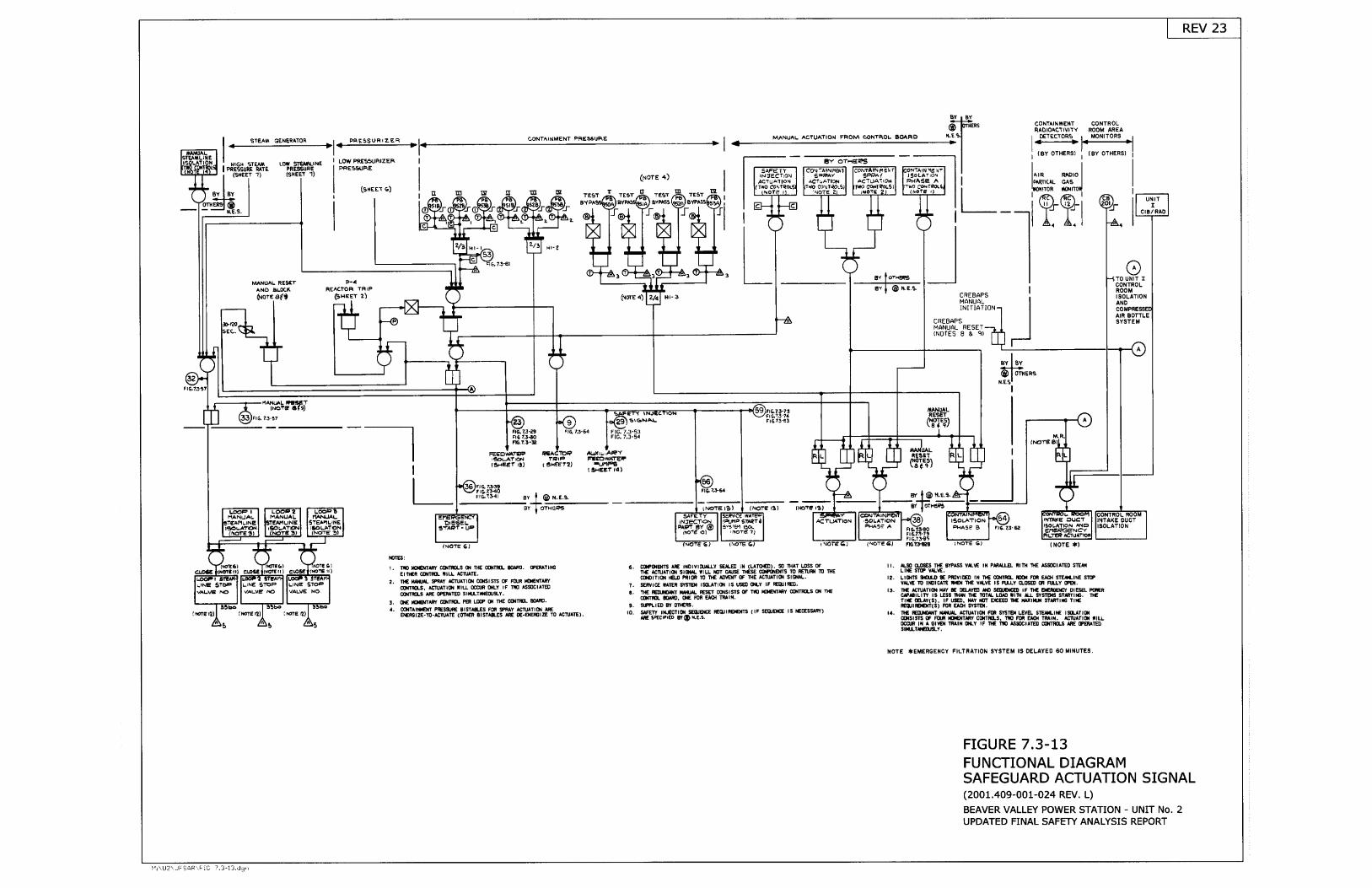
REV 23
H$IIEEEilAV
ACfLATI+l
Ul'll Trcr B/
4t
4asftP-{
REACTOR TFIIP
6HEET ?)
IVTANUAL EESETAHD BLffi,I1
AtS0llTtONPHASE B
INJECf,QHPAFT EY @
ftoTE 'o) -tF')neSvgrErt iSOL
I Norg ?i
rr.JEi 5?6FNo VALVE
'€STEP
VALVE NOS-lOF
BY
CONTAIHIJIENT PRESSURE MANUAL ACTUATION FROM @BIROL BOARD r{.E.
CONTAIXITTEHTRAOIOACTIYITY
OETECTORSH
COHTROLROOI' AREAMOI{ITORS
STEAIA GENERATOR PEESSUEIz.EB
(BY OTHERS) {BY OTHEHSI
lltcr{ STE trPRE55UfiE RATE
($tlEET 1)
LOU SNE\ilL]NEPRES6UFE(sHEEr 1)
LO'V PRESSTJRIZERPf,IE5S{.IRE
EY OTEETS
Roro I
GAS I
ffiifioc
Bi
(NorE 4) AIR
gY BY(sneer c) tr TI TE$T r TEST TEST E
BYTEST
CYF!ASs
.l
Ht- Ht-z
6.73-61
3 E, fot*66 TO I
(NCrE 4)e' | @ rr.s.r.
CREBAPSMANUALINITIATION
CONTEOLROOMISOLATIONAHb
t{r- 3
coAIR BOTTLE
CREBAPSMANUAL RESET(NOTES 8 & C}
SYSTEH
evlev-+@ lmtsns
N.E.SlFtG,
HAI.{UAL f,'TETtNo"E cfs)
6, ?S-!7 SrCtNAl-1r.5{
Ft6FIG. (NOTE
I
FEEtrYI1{?ETrEaLAttof{,3ragEf r!) ri-{,lFB
t SHeEr .4)
7S:t9,3{o?l{r7J.6a
t\roTE t3) (NOTE r:Il trETG 13)
52
(rlofE 6 )
]SIES:
!. Til' littrtrraf c(I.fiIl.s o{ r}E (tltTHL cufiD. FgHrTlliGErn'fi ctllIEL illl lgruAIE,
2, rlf HrrurL sFnrY rgrurrlor oilrsr$s 0F FUJE r{tEl{TAFrcsrl$s, lfruATlol ,lLL $ctn oilLY rF trE ASglGlarEDCO{T(LS TNE CEEATEO SIIIJ-Til8,'SLY.
S. Of TOEJTAFY TITIIE PER UIF O{ IHE COIIEL T}TE.a. cfltTilflE{r FESSJf,E Ersilc.Es Fffi spF y AcrurilO{ l8E
S'EfiGIZE.TO.TCruATE (011#F EISTTS-ES TiE OE.EIEFGIZE TO ^SIUAIE}
t (roTE I ilOTE {:}
ELotE II il6. fiIf,SlElTS rnE lflolvlgJllrY SElrEE lH (L 1U€), SE lllAT LDSS 0F
Tf AEruATIOI SIOIIL IILL IOT UIJSE ]ICsE OOfiilB{TS IO RflIJil TI IHEcoolTloll l€.Il Pf,|ofi III llf llrl,Et{r {F IHE rcll,lTl{x slB{tL'
?. SERUICE IAIEE Sr$IEl lS(LATl0{ lS US€o O,l.Y lF fiEqrlfiED.
c, lllE lEUlElllr llI{JlL RESET COlSlSrS 0F IrE l0G{r$Y cq{rm's fi{ Tl{Ecilfim. rffiD, oE Fof Etol rnalf.
t. sfFLrEU Ef onfrEl.
II. ILSO CI.6ES TTE SYPTSS YIYE II{ FIRAIJJL TIIH lHE ISTEIAIED SIEIHLITI SITf YALYE.
r?. LtErls rflto E Pfl)vrEE lN n{E fixrntI. mox rE EAo{ SrErt lliE snFVTLtIf ID IIOICTTT l{E{ THE YTLVE I$ FJIY CLSEP (n FTIIY IFE{.
Ir. nc rflulrror HaY E E-IYEE r.o sEg.E(Eo rF tr{E ErEiEEr, urEsEL pffiRcfl8llrTy ts LESE n,lll{ I1I ][TtL L0r0 ttllr rr sr$Els st5rt]G. ttfTllC E_AY(S]. tF tED. t{ t r{tT EtEfo I{E Hililtll sTlf,fll$ ?uf'nEIUTiEf'{I(S) Fon El0{ sYslEr,
lr, m Eu.tErl{t ruaurl. rfiurTt0l Ffi sttlEr LEvg- sTErlt-ttf tgq.ATtotctltst!}Is (f Etn rf,E{Tlfrf c{{Tf,.s. Iilt FIf, E or TRIll4, AEruAflC{ ilLLffi0.F tft A gnEr t8 l1{ ilLy rF m IE rssDctAlttr oo{mol.s af,€ (FE|IEI)slItLTilfitrLY.
f tmEeI ltgrEtI I N6rE 12) ro. s FErY rH#rl0{ $qJsrcE EOJIRA€{I8 (lF SEqr$EE ls t€cEssaFY)tnE gPECrTr€o rY o r{.E.s,
5
EOTE ,}EHERGEHCY FILTNATIOTI SYSTEM 13 DELAYED 60 MIT{UTES
FIGURE 7.3.13FUNCTIONAL DIAGRAMSAFEGUARD ACTUATION SIGNAL(2001.409-001-024 REV. L)
BEAVER VALLEY POWER STATION . UNIT No. 2UPDATED FINAL SAFETY ANALYSIS REPORT
l.tr.U2r.iJF iAR'.F lC 7.3-i3..Jc,,
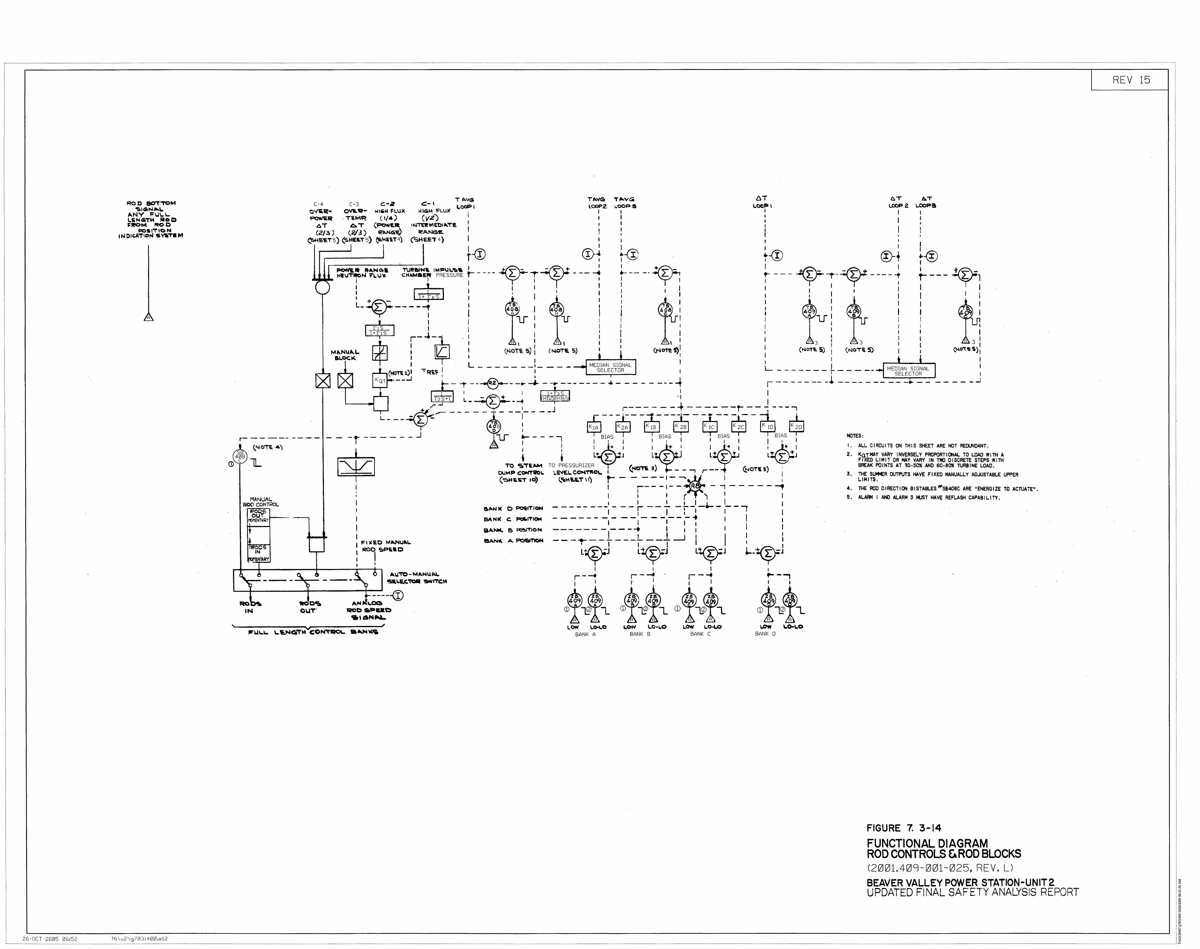
~-------------------------------------------------------------------------------------------------------------------------------------------------------------------------------------------------------------------------------------------------------------- ----------------------------------------------------------------------------------------------------------------------- ----------------------------
ROC BO'T'TOM "!.I <iN.._\.
~NY FU\..1.. l.,.liNCiiTH J;IO C) FIIIOM ReO
!IC)S.I'T IC N INCIC.A'TICN SV'Io'T'•M
A
25-0CT -2005 06:52 M: \u2\g 7 0 31400.e 12
T "'VG TI>."G C-4 C-3 c-z ~-I L.OOP I LOCPZ
~l'l-~- ~~- H16iW FLUX fiiGiH l=LWC I 'F"'W'ER . TEMP. ( 1/4) (vz) I I
AT 1 t-IIIE'R WI E'OI"-T£ I I
T"'VG 6T O.T b.T I..OOP$ I.CCP I LOOP 2 \..OOPS
I I I I I I
I I I I I I 0. T (P'OWtE.It
(2/:3.) (2/ 3) ~""'Civ) ~I>.NG£. I I I
I I I I ' • r ' I
~E'ET5) (SHES.T5) ~\oliiT4) (SH e.e."T 4) I I
I I I I I
CD~ I I I I t-® I t-0; t-® ®-' ~@
..----------'-' _ ___. ---. - 1 1 1 1 1 JIOHI,IIt IIIA,Netll TURIWWS. IMPIJ\..'it~ I ..tJ'~ __;;,;' + __!t~- ~ ~ I ~
..,.~HIIJT'rN~L.U"'C cH~aE~ PREssuRE i---- 'T' T -.T ---; ~----,Tr; f --- ~- ;- -f ----; ,_---- y 1 (> r I I I I I I I I I I I I I
XX
: l+(cc; 1 .l I 1 I I .J..... I I ..l I · I I I I L-~---- -f1
1 1lo'~~ 1 ~?a> : : (4T~r:.~ ~ l (.;rcr~) : ~~ l : r:;rl : '9' II lJ I V ) ~ c \ rl I A 1.f I ~e I I ~.:o-n's I 1 I I I u ~ I 1 I I U~
J+ns 1 1 •1 1 1 1 1 I I ~ r- -'- i · 11 I I I l I I I
I) II'
£ 1 : A I I I ~~~ I A 3 A 3 I A 3 I : I r 1 (NoT~ s) 1 (t.loTE s) ! : ~~ s>' I (Nor~ :t) : (No• e. 5) 1 ~ <t-~O"t~ S) 1 I L I I • I I I .L I I
I · I I 1 r-_....l __ ,a_ t_, I L - - - -- -_I_ - - - MEDIAN SIGNAL I I
~-2~ TR~~ ~- ~ - --@-- -~ ~1 - -r --- -- -s~L=T~R- - - - ---4 ~ ~~~~~~-~I = ~ -~ ~ -_--:_ :~~~~f~A~ * I I l+I"3S . I I
I --~--_J
ns+t L _ - T'-+ _ _.. Hl.45l(HI5S 'I I + ,r-' I J ~------ --+ ---- --r- --------,
L__ --~L:k------ i- --,---- r+:, ---,---~ -~- ;J.-- ;;t;- ;;i, J-, T @gs) : ~ K2A ~ ~ ~ qSJ Cri ~
NOTES: ~ - - --- - - - - - - - t - - - - - - _j U ._ - - - I BIAS I BIAS I 1 BIAS BIAS I • I I' I I' I I I I ~ (.NOTE 4) A 1 I I j: I I l.+ I I _,l+ 1 1 •g+ I ( 4~v • • L~ L ,;1 Ltc L: )1.] L~ L }!J l~J
I. ALL CIRCUITS ON THIS SHEET ARE NOT REDUNDANT. 2. KQTMAY VARY INVERSELY PROPORTIONAL TO LOAO WITH A
FIXEO LIMIT OR MAY VAFf'f .IN 00 DISCRETE STEPS WITH BREAK POINTS AT ~0-50% AND 60-80% TURBINE LOAD. <D c lL ~ 1 r To -=aT&.,.... ro PREssuRIZER T ,, } r '+-' OUMP COMTROI. LINE.\.CO!<o4'M'C\.. I . \!'IO"R 3 ..-- - -, r -- • (i:.!oT• !) i
'
MANUAL ROD CONTROL
~~,.s MOMENiAI0.~-1---- ---,
~O<:o IN
tmeNTAr;rf
I I . I
I I I I F I lt E 0 M li>.NUA.l.. : liOI ~s.ac I '
___ __.'\.~---~ 6 A \I 'TO- M .. N\UI•"-~\.I.C,'TQR ~I'TC:~
RO~ --IN
~-----@ AN~ \.OG
QOCt.PIUlO .. ,6 ... ~
(SHS.~ 10) (,"DI-It.;.'T I 1) t- - - - - -I - ...... .iJ I I
I . ~-- - I- -.., R~ - -; - - - - - --., I l I ( -. "''I I I
8A.NI( OPOSITioN ------·--1 - --~--..!__!__I_.__ I __ ) I I 1 I :1 I I
SA Nl( c. ~ITIOM - - - - - - - - - - - - - - - - -+ I I I I I I I 1 &I>.NK. e. ~ITION ~-- - - - - - - - ... I I I I I I BANI(, A F'IOSillON - - - .... - _l - - - L - _l. _j I I I l • I I I I I
L~J L'VJ l~J ~-~J I I I 1 r-___. r-___. · r--+ .,..._..,
1 I 1· I 1 I I 1
~) (i d~ (}~, , \} ~ a~~ J ~ <D ~ l_ CD ... ~ L. CD' v~'~""'L CD r-~ ""L
A A A A A A A LOW Lo-1.0 LON LO-L.O LOW 1.0-LO I..O'fi l..o-t..O
BANK A BANK B BANK C BANK 0
3, THE SUI+ER OUTPUTS HAVE FIXED MANUALLY ADJUSTABLE UPPER LIMITS,
4. THE ROO DIRECTION BISTABLES ,.,.SB408C ARE "ENERGIZE TO ACTUATE". 5. ALARM I AND ALARM 3 KIST HAVE REFLASH CAPABILITY.
FIGURE 7. 3-14 FUNCTIONAL DIAGRAM ROD CONTROLS &ROD BLOCKS (2001.409-001-025. REV. U BEAVER VALLEY POWER STATION-UNIT2 UPDATED FINAL SAFETY ANALYSIS REPORT
REV 15
:; ~ ~ ~
~ .. 0
8 ~ ~ ~ ~ ~ ------------ .. -------------- --------------------------------------------------------- -···. ----------------------------------------------------------------------------------------------------------- --·----- ··--------------------------------------------- ----------------- ······---. -------------------------------------- --- ------- ------ ----------------------------------- .. --- .......... ---- ·--------------------- ... ---- ···---------------------------------------------------------------------------- .. ·-·--.. --- .. --.----------- -----"---- ------------.------------------- -·-·· ------------------------------------------------------------------------------------------- --- .. ---.--------.------ .... ------------------------------------------------------------------ - ....
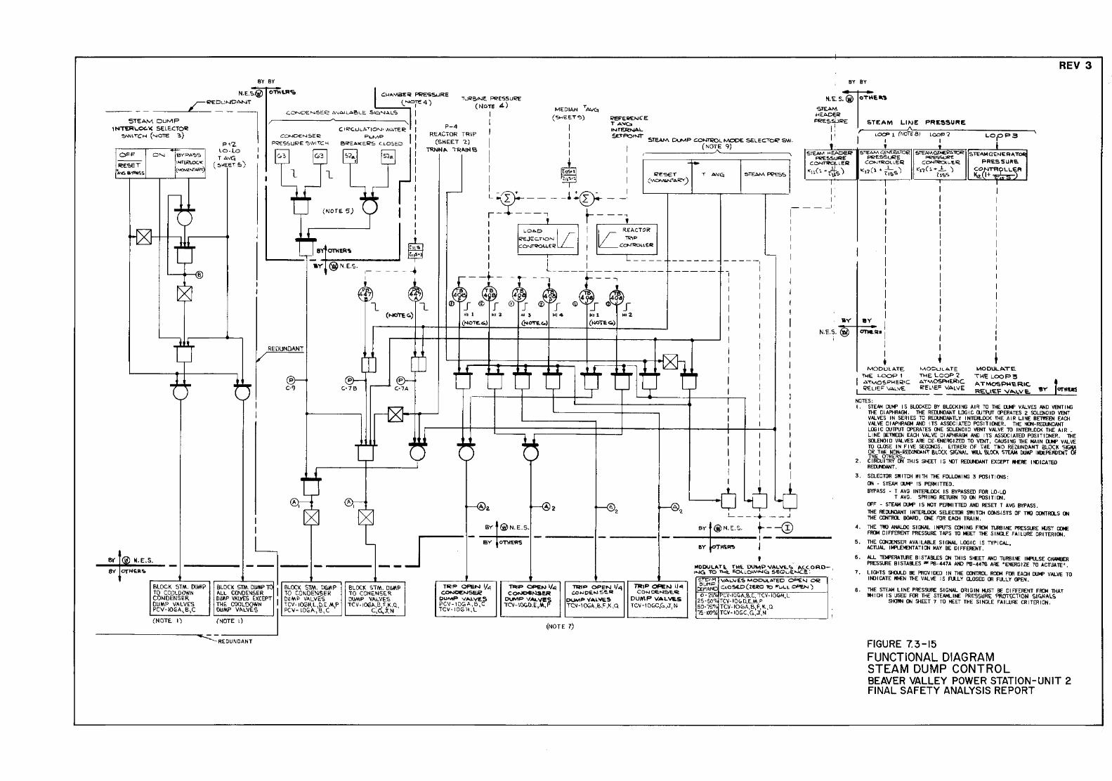
REV 3 BY BY BY BY
N.E.~ O!Mt.RO:.
--- -- ____ c_r __ !i?EDU~ANT 5TEAN\ DuMP
!NIERI...OC.\( SELE.CTOii! ~WIT"CH ("-'OTE 3)
P1'2. LO-lO TA""
( s><e:eT 5)
I I
CONDEN::.ER PI<'ES'>UF<-E ':>WlTC>-1
I c: IRC.ULATIO"-J• JV.>.TER I
PuMP Jl 6REA~<E!i?S LO.OSED I
Ej ~! S2.._
I
(NOTE. 5) I :
aY' @ N.E.S. ,--I
~ l_
----+
T;J~B,NE PI?ESSllRE (NOTE 4)
P-4 REACTOR TRIP
(SKEET 2) TRNN"' TRAIN 6
I I I I I I I I
MEDIAN TA\1'4 (5>-!EET":l)
I t
~
REF"EIIE>-!CE T AVC::o INTERNAL
SETPOPNT" STEAM Do..J!V.P COI-J"11<CL N\ODE SELEC"ToiC' SW. (NOTE 9)
,------~~'-~-------,
L L ---l_r r- -----, I ;
I r---, I I I I I
- -t- -· !;
4
_[ ® J "' I
(NOT£.4,)
... ~
"' z
4g CD I
I
I I I L ___ _ L_ ____ ~-- ------
- -- .__---. I •
®€~J (j) ~_f ~~~ _r "14 "' 1
(toCTECO.)
-1 I I I I I
i I I I I I I
i
.._ I I I I I I I I
! ' ' I I I i I
I I I
I I I
I I I I I
I I I I I I I I I
I I I I
I I
-
I I I
~6 -6-6 L---+- __ .J
BY @ N.[.S, BY t~N.E.S. SY r OT\IER'S ------ ----- +---@ - ----1-----1-
1
'
,. 5TEJ>M l-1 E.AOEIC'
I'<CE!>5WRE C ONT"IO'qC L E R
"a(l •r*s) I
I I'
___ I
N.E.S.
------=----.t..SJ" ~ ••• -E..-s.. j - r--- --_ .-.--- ___ _j 8Y OTI-lEil"' r------~ ~ ~ ~~~~A~l ~t .. ~':lfC:l'\l~~~l~~<.pRO-,
BLOCK STM. DUMP BLOCK STM. Dl!MP TC I BLOCK STM. Dll~P BLOC!( STM. DUMP m1P OPEN lfo<1 TO COOLDOWN ~Ll CDNDE»SER TO CONDENSER TO CONE.NSE.R ~~ COt.IDENSER 011,1\P VAlYES EWXNCEPT I llUM~ VALVES DUMP VALVES D"""""' VALVES DU lf.P VALVES THE. COOLOO TCV-IOGH,L, ll,E ,M,P TCV ·IOOA,B, ~.K.Q, PCV- I O(C A, B, C PCV-IOGA,B,C DUMP VI'.LVES PCV-IOGA, B,C C,C..,J, N TC\1-10(0 11, L
(NOTE. I') (NOTE I)
REDUNDANT
~u:> OP!i:N 1/.t:J, coNDE~ER
DUMP VAL'II!S TC\1-I~D.E ,M, P
~o:> OPEN 1/~ <::o>JOEfoJ Sii.IO
DUMP VA.L'iE.S TC'I-1 OG~ ,B.~ ,K ,Q
(NOTE 7)
~P Of'EN I!~ C O>J CEON"'ii. Q.
DUMP VAL\IE.S TCV -1 O(OC,G.,J, N
S!E'.t•M VAL.VES MOD\.Jl.AiED 0$=£~ Ofii2: &~~~D C<O~ (ZE~ "10 ~LL OPEN ) o · 2SOk PCV·IO!OA,B,C, TC\1 -IOIDH, L
25 ·50'!: TC\1-IOO.O.E.M}' 50·75"1 TC\1-IOlDA,B,~.K.Q l5 ·100% TCV·IOC.C, G,J,N
' STEAM GENU<tl.TOR P!<'E.SSlRE
CDNT"OtOLLE.R
"•2 (1 • T~~s)
l I I I I I I I I I I I I ..,.I
~'"·I I I
• MODULATE. ~E LOOP 1 .>.TMOSP'-'ER•C '?E:LLE"' VALVE.
NOTES:
PRESSURE
• STEt>MGE>EI?AlOR ~~ C~L~R
.. ,'2(1+..!.. )
""'"' I I I I I I I I I I I I I I I I I I I I
• MODULA.fE ~E LOOP2 AT'VIOSA<ERIC. !eEL IEF VALVE.
~ S~ AM G. <;;N ERA "TOii
PFIESSWRS.
~clt~~FI I I I I I
I I I I
' ~00\lL.I>.TE.
1'1--\'i; LOOP:5 AT...,OSPHe.RIC. R;o;I...IE'F V ..... LVE.
I . STENol [lJiof' I S BLOCKED BY BlOCK I NG A I R TO lHE 11M' V AI... VES AND VENT I NG lHE w I APHR~ • THE REIJ..tiOANT LDG I C WTPUT lPERA TES 2 S0LEN0 I D VENT VAlVES IN SER I ES TO RElX.NDANTL Y I NTERlOCK THE A I R ll NE BETI'IEEN EAO! \1 Al VE 0 I APHF!AGI AND I TS AS SOC I A TED POS 1T I ~ER. THE NCJI. REIUIDANT LOGIC WTP\JT lPERATES OOE SOLENOID VENT VALVE TO INTERLOCK THE AIR . L I NE BE1l'IEEN EAO! VALVE D I APHF!AGI AND I TS AS SOC I ATED P0S IT I ONER _ lHE SOLENOID VALVES ARE DE-ENERGIZED TO VENT, CAUSING lHE MAIN 11M' v.&I...\IE TO Q..OSE I N F I \IE SECCNOS . EITHER OF THE TW 0 REDUNDANT BLOCK SIGNA OR THE NON·RE~T BLOCK SIGN.O.l WILL Bt.OO. STEAM DUMP INDEFEMDOIT OF THE OTHERS.
2 . C I RCU I TRY CN TH I S SHEET I S '(IT REIUilAHT EXCEPT JII£RE Hll I CA TED REOJtt:JNIT.
3 . 5aECTOR SW I Tai WI TH Tl£ FOLLOW I NG 3 POS Ill OOS : CN • STEAM !lM' IS P€RM I TTEO. BYPASS - T A \IG I NTERUJCK IS BYPASSED F"OR LO· L0
T AVG. SPRING RETURN TO ~ POSITICN. OFF - STEAM CUP I S NOT PERM I nED AND RESEr T A \IG BYPASS . THE REWNDANT IIITE~ SELECTOR SWITCH CCNSISTS OF T1110 CQiTIQ.S ~ THE CCNTRa. IIOARIJ, IN: FOR EAO! TRA I N •
4 . THE T1IIO ANAl..OC S I GNAl I HPUTS CQot IN; FIDI TURBINE PRESSUIE !oUST COl£ FI'Ot Dl FFERENT PRESSURE TAPS TO IEET Tl£ S IHGI.E FA llliRE CfllrERI~.
5. THE CCNDENSER AVA ll.ABLE SIGNAL LOGIC IS TYPICAL., ACTllAl IK'!.DENTATI CN MAY BE DIFFERENT.
6 . ALL TEM'ERA lUlE B I STABLES ~ TN IS SfEET AND TUR!III£ 114'll.SE CHAMBER PRESSLJlE BISTABLES "' PB-447A AND PB-447!1 o\RE "ENERGIZE TO ACTUATE".
7 • ll GHTS SlfJlJ...O liE PR0\1 IDEO I N THE CCNTRa.. RCXJo1 FOR EACH 1XM' VAL. \IE TO I NO I CA TE WI£N THE VAL \IE I S FLU. Y CLOSED ()l FUlLY OPEN •
8 • THE STEAM ll NE PRESSURE S I GNAL OR I G IN loi.JST liE 0 I FFERENT FIDI lHAT ~ I CH I S USED FOO THE STEAtol...ll£ PRESSURE PROTECT I ON Sl G.N ALS
SfiOl'tl ~ 9iEEr 7 TO MEET THE S I NGLE FA I Ll!RE CR ITER I ON •
FIGURE 7.3-15 FUNCTIONAL DIAGRAM STEAM DUMP CONTROL BEAVER VALLEY POWER STATION-UNIT 2 FINAL SAFETY ANALYSIS REPORT
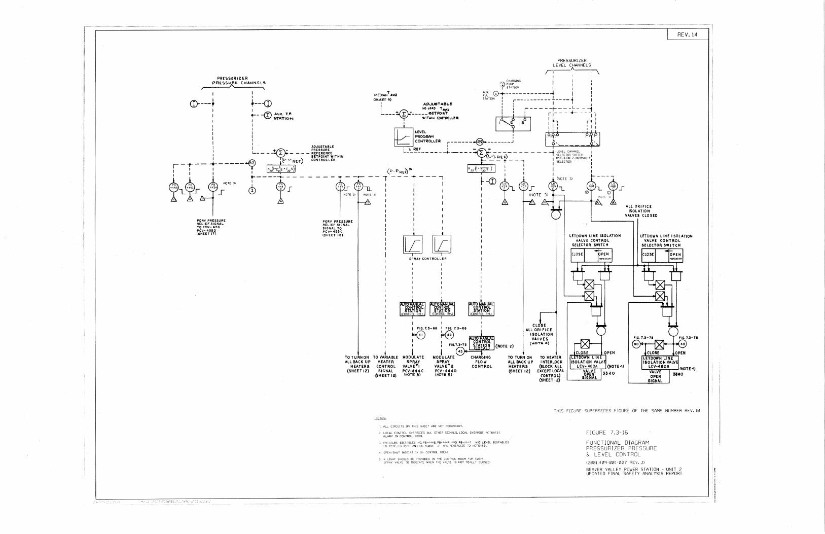
PRE':>SURIZf.R PRE':>SURt. (IIANNtLS
I
CD----~ I I
I t----@ Aux. l'.P. I ,.TATION I I I I I
: · ADJUSTABLE PRESSURE
L_ - - - - - - REFERENCE I SETPOINT WITHIN I ..(R2) (P-<>R~i:l') CONTROLLER
~-r-- ~----- y K (<•~•r s)
~L ~s ~ ;""' ~--~-! ~ ----PORV PRESSURE RELIEF SIGNAL TO PCV- 466 PCV- 4!5!SO (SHEET 17)
PORV PRESSURE RELIEF SIGNAL SIGNAL TO PCV-4!5!SC (SHEET 18)
TOTURNON ALL BACK UP
HEATERS (SHEET 12)
CHARGING (I) PUMP
PRESSURIZER LEVEL CHANNELS ,-----"---,
T STATION I I
MEDIAN,. AVG AUX. 0+------------~ I F.P. i I J.
(51.1EET9) STATION 11 :---------- ~---- j II : APJU6TASLe 1 NO •••c ,. -. 1 : r-- - - -r--- -1-- - --1 L---~----;_,-rr~~~T:~:oLL!It ~I t 1 ;~--- +--- __ 1 :
' I ... , r'1 I G 11: :11
~~!;!AM I ,.b,$,6 Pi}PI
I TO VARIABLE
HEATER CONTROL SIGNAL
(SHEET 12)
COIJTRCX.LER ~------...§.-------j' i',_ -~"-' L REF ' - + '------- ___ __._____ L: -------
(L-L~>.o) _ __J LEvEL CHtlNNEL
( SELECTOR SWITCH 1
I I
I
llZJG SPRAY CONTROLLER
I FIG. 7.3-66
K0 I FIG. 7.3-66
1&(0 I I
! MODULATE
SPRAY VALVE"'I PCV-444 C (NOTE 5)
I I
I MODULATE
SPRAY VALVE"' 2 PCV-4440 (NOTE 5)
-- ~---,
~~~~ I
I (POSITION 2. NORMA.LL '( I SELECTEOJ :
CHARGING FLOW
CONTROL
I
I I ~-- ..... _,
® 11_ 4~~L .. ®s r-+---@+~~N:'E ?1
CLOSE ALL ORIFICE
I SOLATION VALVES
("o"Ta "')
TO TURN ON ALL BACK UP HEATERS (SHEET 12)
TO HEATER INTERLOCK
(BLOCK ALL EXCEPT LOCAL
C'ONTROL) (SHEET 12)
ALL ORifiCE ISOLATION
VALVES CLOSED
REV. 14
THIS FIGURE SUPERSEDES FIGURE OF THE SAME NUMBER REV. 10
l. ALL CIRC!_I[TS ON THIS SHEET ARE NOT REDUNDANT.
2. LOCAL CONTROL OvE.;RIDES ALL OTHER SIGNALS. LOCAL OIIERRlDE ACTUATES ALARtv'. IN CONTROL ROOM.
PB-444!" AND PS-444A AND LEVEl 8I'STABLES 2 ~RE 'ENERGIZE -:-o ACTUATE'.
SF RAY
FiGURE 7.3-16 FUNCTIONAL DIAGRAM PRESSURIZER PRESSURE & LEVEL CONTROL (2001.409~001~027 REV. Jl BEAVER VALLEY POWER STATION - UNIT 2 UPDATED FINAL SAFETY ANALYSIS REPORT
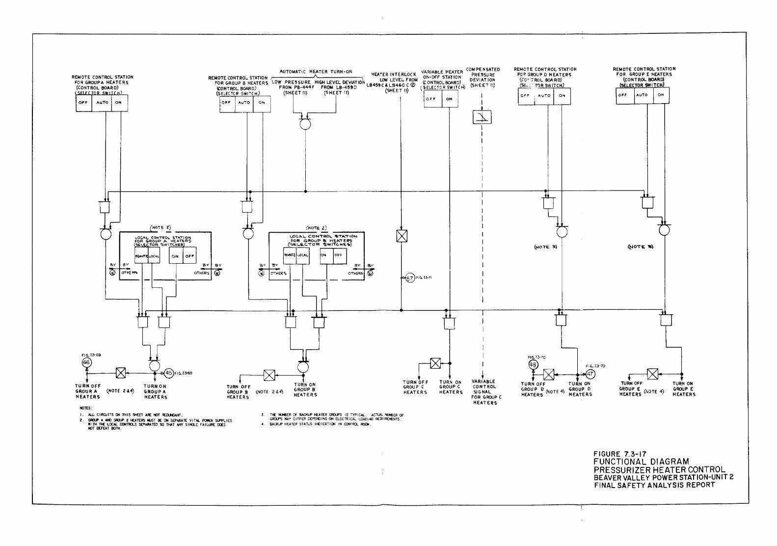
REt.IOTE CONTROL STATION FOR GROUPA HEATERS (CONTROL BOAR D)
( )
TURNOFF GRO U R A (NOTE 2& 4) HEATERS
t<liTS:
TURN ON GROUP A HEATERS
I • ALL C I RCU I TS at TH IS SHEET .t.RE t()T REO..N:IANT •
AUTOt.IATIC HEATER TURN-ON VARIABLE t<EATER COt.! PE NSATED REt.IOTE CONTROL STATION , HEATER INTERLOCK ON-OFF STATION PRESSURE
FOR GROUP B HEATERS LOW PR E5SU RE HIGH LEVEL DEVIATION LOW LEVEL FROM (CONTROL SOARD) DEVIATION "ONTROL BOAR D) FROM PB-444 F FROM LB-459 D LB459 C & LB46° C ® ( 'i ELECToR SW 1 T C HJ (SHEET II) (SELECTOR SWITCH) (SHEET rl) (SHEET II) (SHEET 11)
sv BY
OTHERS
0"1 !
TURN OFF GROUP 9 (NOTE 2 &. 4~ HEATERS
(HOTE Z) '.PC. II.. I.. CON'1'RO\.. ,"T..._"T ION ~OR GROUP 1!o HE_,O..~E.~
(<a.lO.LEC.""'"OR '5W 1'1'C.H'E.1io)
TURN ON GROUP B HEATERS
TURNOFF GROUP C HEATERS
TURN ON GROUP C HEATERS
I I
[$] I I I I I I j
• VARIABLE CONTROL SIGNAL
FOR GROUP C HEATERS
2 • GID.J' ~ ANl GID.J' S fV. TERS ~T BE at SEPARATE V I T AI.. f'OWER SUPPL I ES ~~ tf:~~TH~ SEP.W.TED SO TH.t.T N1Y Sl~ F~IUJ'lE OOES
3 . T>£ ~R OF BACKUP foE A TER GI10UPS I S Ti'P I CAl. . AC~ '"'-MIER Of GIUPS ~ Y 0 I FFER OEPENJ I NG OH ELEC TR I CAl. lDAIJ I NG REOJ I REM EN TS .
4 . BACKI.I' H~ TER STULS I NO I CUI ON IN CONTRQ ~.
REMOTE CONTROL STATION FO~ GROUP D HEATERS
(CO ''7 ROL BOA RO} (SE.. c ' T'l R SW lTC H
~a~· ; AUTO
TURN OFF TURN ON GROUP D (NOTE 4) GROUP D HEATERS HEATERS
TURN OFF GROUP E (NOTE 4) HEATERS ·
FIGURE 7.3-17
TURN ON G~P E HEATERS
FUNCTIONAL DIAGRAM PRESSURIZER HEATER CONTROL BEAVER VALLEY POWER STAT ION-UN IT 2 FINAL SAFETY ANALYSIS REPORT
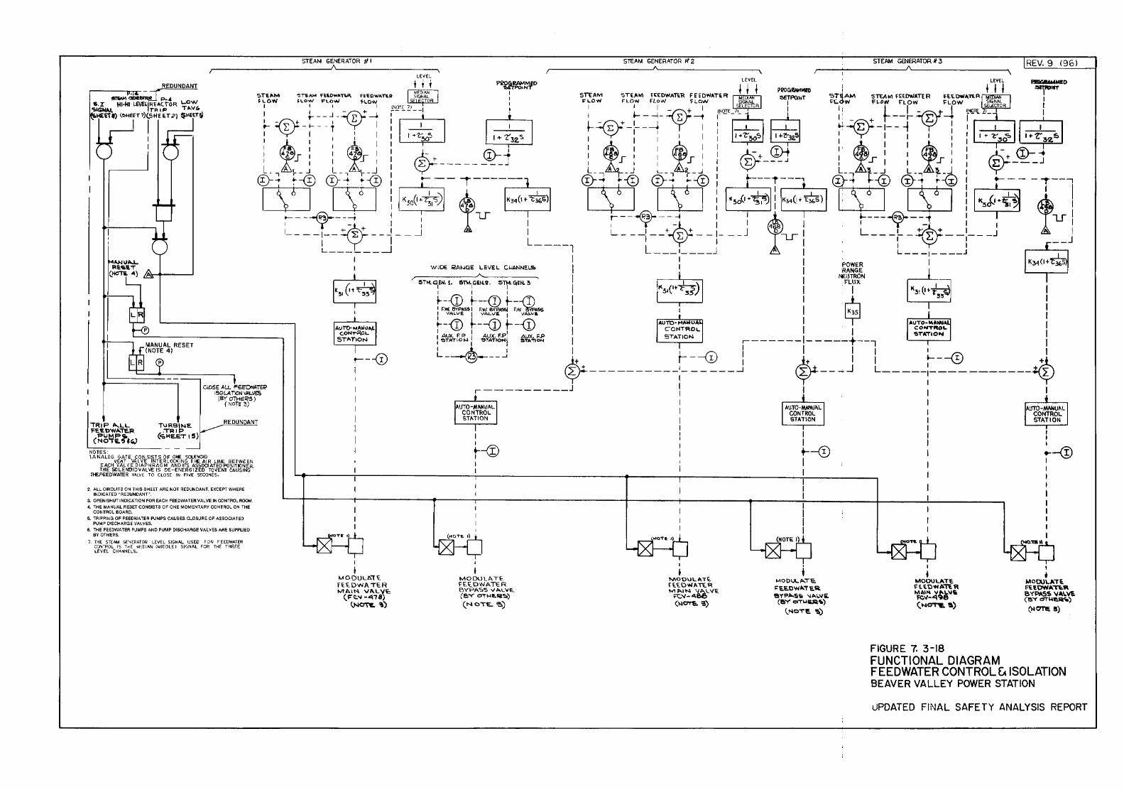
TRIP l!o...LL FE£ DWA..Te.R.
PUMP 'it (NO!E.5t(J
NOTES: I. ANALOG GATE CON 51ST S OF .ONE SCUNOID
VENT VALVE INTER LOCKlN5 If£ AIR LINE BETWEEN EACH VALVE DIAPH RAG t.! AND ITS ASSOCI ATEO POSIJKlNER. THE SOLEfiOIDVALVE IS DE-ENERGIZED TOVENT CAUSING
.ltE.FEEDWATER VAL\' E T 0 CLOSE IN Fl YE SECONDS.
2. ALL ClRCUHS ON THIS SHEET ARE NOT A EDUN DANT, EXCEPT WHERE lNDICATED "REDUNDANT".
J. OPEN/SHUT INDICATION FOR EACH FEEDWATER VALVE JN CONTROL fi:(I()M.
4. THE M A.N UAL RESET CONSISTS 0 F ONE MOMENT A RY GO NTROL ON THE CONTROL BOARD.
5. TRIPPING OF FEEDWATE-R PUMPS CAUSES CLOSU A E Of ,!!..SSOCIATED PUMP DISCHARG-E VAl liES.
6. THE' FEEDWATER PUMPS AND PUMP DISCHARGE VALVES AAE SUPPliED BY OTH'ERS.
7, TH£ 'STEAM G£\IERATOR LEVEL SIGNAL US EO F 0 G' FE E~AfEIR CCNH'O L IS T-HE M':D LAN (M I DOLE ~ SIGNAl FOR THE THA.EE LEVEt CH.r..NNEL'S.
STEAM GENERATOR 1f I
t---0 I
I
I MODULA"T£ f££DWA TE.R MA.I~ VA.L'{E (Ft.~ -4:1'78) (N~'!o)
I I
t---®
MODUU\TE. FE.E.DWATE. R BYPA5S VALVE. (BY Oi"'E.Iii':::o) (NOTE..~)
STEAM GENERATOR lf2
I
• MOOU\;;ATt fE.E.OwATE.R MJ>..\N VAlVE. i=C"-486 <~-~~~)
I I +----@ I I
t ~<~ODUL,I>..i"l:;
FE.E.OWA.T E. A. BYP"'S'D 'IA~\fii.
(l!oY 0"1"\.IUi'i.)
\.NOTE~)
STEAM GENERATOR II 3
FIGURE 7. 3-18
REV. 9 C96l
I I I
... --<!J I
I • MODULATE FU.OWA"T"-tt BYPASS V"Wt. (e.Y d'Tioi1!:.A._)
(W 0'1"15. !l)
FUNCTIONAL DIAGRAM FEEDWATER CONTROL fA ISOLATION BEAVER VALLEY POWER STATION
uPDATED FINAL SAFETY ANALYSIS REPORT
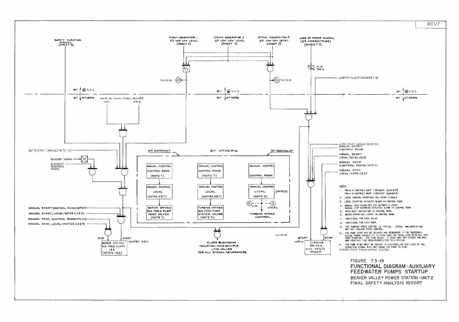
S,i..I'Ei'r' I N~'EC.T\ON 'SIGNA..\..
(. S>IE 'E.,- 8)
@ N .. E.S.
OTI-\EI'I.<;, TRIP 0~ !""-"'IN f'E.EC PL .. d"\PS
FP·i FP-2
AUTO-STAr:-T AM SAC ( NCTE 12)--------------,
BLACKOUT SIGNAL~ BLACKOUT SEQUENCE ~
"""'L T ~-------,
I
t MIINUAL STA Rl'; CONTROl.. ROOM(IJOT£5}-----------,
MAr.JUAL START, lOCAL(NOTES 2,3¢8)
MANUAL STOP, CONTROL ROOM(N07tS41f9)-------,
M!\NUA L STOP, LOCAl.. (NOT E.S 2,3 ~ 8)
t:-- !
I
5TEI\M Gerve"P.To.ct 1 Z/3 LOw LOW LEV i:L-
(SHEET 1)
FIG.7.3-53 @r--
<;;TEAM GENERATOR 2 2/' LOW \.OW LE.VEI..
(SH&ET 7)
STEAM G6NERATOR 3 2/3 lOW LOW ~VE\..
(SHEE.T 7)
~FIG,CJ-19
______ s_Y----jl-@-N. E._ s_. ----- -ISY O"'T"HERS
~T REIJYND.O..WT BY OTHE..I"'.':> I<OT~fiD.O..><'T
----........ - / -
MAIVUAL CONTROL MANUAL CONTROL MA"--UAL CONTROl.
COI\ITROL ROOM COIUTROL ROOM
(lllOTE 7) (NOT£ 7) COt.IT"ROl ROOM
l 1 ~ I MANUAL CONTROL MANliAL CONTROl MANUAL COtJTROl
lOCAL. LOCAL. LOCAL (NOT'C.9)
(NOTES 2$7) (I\IOTES2~7) (lllOT E. ZJ
i l ~ @;---+---0 MOTOR DRI VE.J\1 I TURBINE DRIVE.t.l C. .. R .. ~ LOCI>.\.. AUX. FEED PliMP AUX .. FEED PIJMP I
FEED VALVES I S"iSTEM VALVES TURBINE. Sf'C.E..C (NOT!: 5) (lliOTE 5) CON TAO\.. _j - -
FIG. 7.3-54 ""~ "'"' MOTOR I:JRJVEN (NOTES 10~11) C:l...O$E aU)WQOWN l~OL..A.,-ION -"'-NO ~Pl..!.
l...IN'i V...._LV!.$ AUX. FEED PUMPS
I ~2 (NOTES I ~6) FO'IIt. ..._1...1... ~T~ GENEAA'TO~
REV?
~~ 01" PC¥1'E.R -;.l<iNI>..\o, ( .<;/' WMOE.R\'OI.."'''"A..Go e..}
(.OS.I-lE.E..,.. 5)
(
' •
r------SAFETY I~JECTICN(SHEET 8)
,.....-------- AU:ro START AIVSAC (NOTE 12) ,------- MpjNlJAL START
COJNTROL ROOM
M~NUAL START .------- LOCAL (NOT~ 2~ 3)
M4NUAL STOP ....---- CONTROL ROOM (NOT<;: 4)
M~'-lUAl 5TOP ,---- LOO:A L (NOTE e $ 3)
ooj-e:s
BY
BY
I . TilA IN A CONTROLS MAFP I :BREAKER NU '-1 B ER. TRA I N B aJN TROLS 1-!AFP ~ : 8REAKER N U ~ 8 E R ..
2 . LOCAL COOTRQ OVERR I DES All OTHER S I GNALS .
3 • LOCAL OVERR I DE ACTUATES ALARM IN C!l-ITROL ROOM •
4 . MN<UAL STOP 0 \'ERR I DES THE AUTCMAT I C START.
@IU .. S ..
O"'T"H'IO,RS
MANUAL ST0° OVERR I CE ACTUATES ALARM I N CON TRU.. ROCM . 5. OPEN/!iiUT INCICATI!l-l IN CONTROL ROCJ-1. 6 . MOlOR OPERA T I NG Ll GHTS I N CONTRa.. ROGL
7.: INOIVI CUAL fOR EACH VAL \'E.
8. INOIVIOUAL FOR EACH ~P.
ST•eT ~TOP (fldiE I!) r---'-T-U_R_B_I_"-l_E.L.----,
9 • THE TLRB I NE SFEEC ~TOOL I S TYP I CAL . ACTUAL I t-f'LEMENT AT I 00 lolA Y NOT I NQ.UJE SFE£0 CONTROL .. THE f'I.M' START MAY BE DELAYED AND SE QJENCED I F THE B-1ERGENCY D 1 ESEL P!li'IER CAPAS Ill TY IS LESS THAN THE TOTAL LOAD WITH All SYS-TB-15 STARTING. THE TIME DELAY. IF USED. MAY NOT EXCEED THE MAX 1-ioi.IM START I N G T I ME REQU I REMENTS FOR TH I S SYSTEM .
ORIY£1\1 1 I . THE PLM' STAll T '"'-.1ST BE SEALED I N ( LA Ta·IED J, SO THAT LOSS OF 11-1 ~ ACTUAT I ON S I GNAL W ILL lilT CAUSE THE PLJ-IP TO STOI' ..
12.~UTO START FROM AM SAC SYSTEM
FIGURE 7. 3-19 FUNCTIONAL DIAGRAM -AUXILIARY FEEDWATER PUMPS STARTUP BEAVER VALLEY POWER STATION -UNIT 2 FINAL SAFETY ANALYSIS REPORT
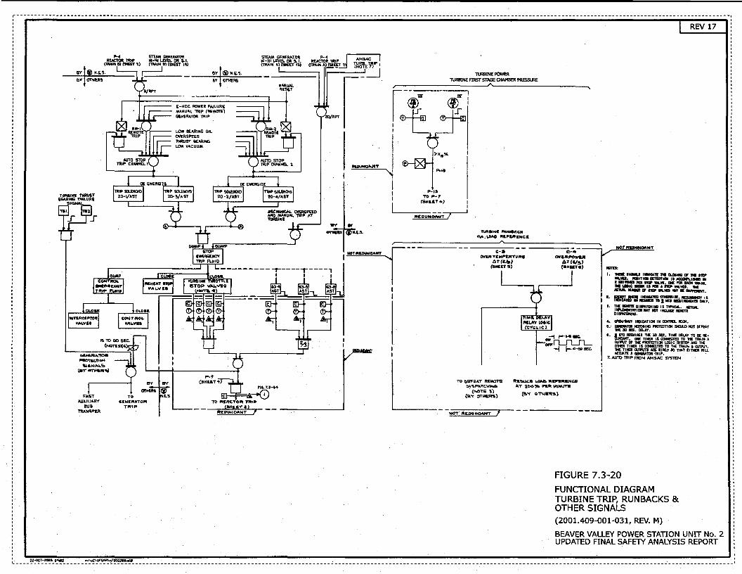
' ' ' '
.... ~g1.)
av I® .. ~.s. BY OTHE~
T~R&IN& TMRUST KARKG f.-.LUAE
"'
'F"A'!.T ~XIUA.RY
aus TftANSFE.R
TO 6ENIPtATO"
TRIP
I'll. 7.3-14
ICI--F=::;t.-.0) TO flt&AC:TOflt Tfltt~
(6M!t&T Z) REDUNDANT I
TURBINE POWER TURBINE FIRST STAGE OlAMBER PRESSURE
P·ll TO P-7
tsH&a.T4) I I
R£DuNDANT / 1
l'Uit .. Na 1'fVN8.4111Ctc v..- .·\.DAD IIII.P'UtS:NCI.
c-a OVUtTlM..UT""&
loTI&<!~) _ .... , C·4 OV& .. NW&It
t.•CIIs> (lllti£Ta)
NT
llltU' I. 1IEa 1.-.. IIBIQTE H G.Giu• Ill' 'DE 111P
-.... ...TKIIIE'IICTtal II ACCDft.l .. aY I •11DB Pill S'ftP WUI, DC mt 1101 TMNI. M LaiC .... II Jill • IV M..VIS. 1H1 AC1WL 11ME1t ar mP WLVIS JaY. DIFPEMHT,
I. ~==-~v='.:a.:=f'~:. I, M .... DIIN1QIIN8 IS '""CM.. MnU1L • UIII.DIJft'ATiat _., IGT tta..UilE JINOlt
01..-rotttG.
4. CPEWSIUT INDICATICJI 1411 c:oma. IIXM. IIi,· GliNEM.ltlll IGI'OIHHG PROTGn!* SHa.LD fiJT rEFEAT
1HE JQ IEC, tELA't'. I. SlD IEGJIIEI lHl 3D SEC. TillE DELAY TO BE M·
IIIOEjT~'"[I"'!£j1r!;•~~1GTO£~iic:Osr=. n:JH3;:!~ •tRED SO 'TK'T EITIER IIIU.
TOR ·TRIP. · 1. AUlO TRIP FlDM AM SAC SYSTEM
FIGURE 7.3-20 FUNCTIONAL DIAGRAM TURBINE TRIP, RUNBACKS & OTHER SIGNALS (2001.409-001-031, REV. M)
BEAVER VALLEY POWER STATION UNIT No. 2 UPDATED FINAL SAFETY ANALYSIS REPORT
' ' ~----~:~-~------~~~!~~----------------------------------------------------------------------------------------------------------------------------------------------------------------------'
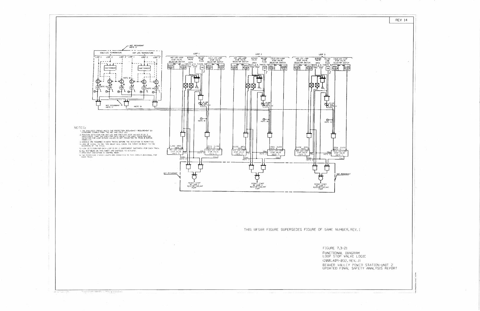
NOTES: 1 lH£ E~CLOSED (!RCU!T Ml:.ET? THE PROTECTION REOu.-.OA"JCY REGUIREMEN 7 BY .. COHBiN!NG SIGNALS FROM To.JE HOT AND COLD LEG. 2. PQS!T!ON OETECT!Qr~ FOR HOT LEG AND COLD LEG STOP_ VALVES IS BY 2
!NOEPENQ[Nf LJM[T SWiTCHES FOR EAC>-1 VALVE, 1 FOR t:ACH TRA!N.PUS!TlON JETECTIQN FOR LOOP BYPASS VALVES IS NOT CONNECTED TO TRAIN 8 DUR!~iG "100ES 1-4.
3. S!Gt~ALS ARE REGIJIREO IN BOTH TRAINS BEFORE THE ACTUATION IS PERMiTTED. 4, L..OSS 1)F SIGNAL TO THE T!t-~E DELAY Wlll CAUSE THE TIMER TO RESET TO THE
BEG!"lN[NG OF T!-JE: SYCLE:_. 5., LOW )fTECTlO"l FOR EACH LJOP IS BY 2 !•~DEPE"'OENT SWITCHES. 1 FOR EACH -:-"lAIN. 6. All BIS 7 A8LES ON THIS SHEET ARE' ENERG!ZE TO ACTUAiE'. 7. OPEN/SriLT !NO:CATION IN CONTROL RQQI-1. 3. TWO PE.:;H;SS!~<E STATUS LIGHTS ARE CONNECTED TO THIS C!RCUiT.!N·:::J!V:OUA~ FJR
t.:.CH -R~lN.
NOT REDUNDANT '
"'!
LOOP I ~-
BYPASS RELIEF COLO LEG LOOP VALVE LINE STOP VALVE
FLo·.t SELECTOR SWITCH
LOOP 2
~-0,--L-EG~LO~D~P---~~RE~L~IE~F~~~~~==~ STOP VALVE VALVE UNE
SELECTOR SWITCH FLOW
PERMIT START OF LOOP 2
REACTOR COOLANT PUMP
LOOP 3
~r·-LE_G_L_OOp----;::BY:;;P::A;:;SS::"--::::-::::--:CC:O-:LD~LE;:;Gc-L:-;OC:O;:"P---... STOP VALVE VALVE STOP VALVE
SELECTOR SW[TCH SELECTOR SWITCH
PERMIT START OF LOOP 3
REACTOR COOLANT PUMP
~ NOT REDUNDANT
v
REV 14
THIS UFSAR FIGURE SUPERSEDES FIGURE OF SAME NUMBER, REV. 1
FIGURE 7.3-21 FUNCTIONAL DIAGRAM LOOP STOP VALVE LOGIC (2001.409-032, REV. J) BEAVER VALLEY POWER STATION-UNIT 2 UPDATED FINAL SAFETY ANALYSIS REPORT
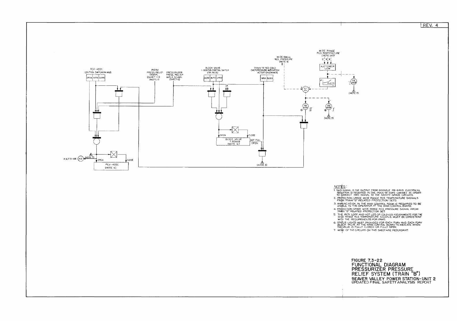
PCV-455C COl·~ TP.OL SWI TO-I (ON MCil)
PC.V-455C (NOTE 0:.)
PORV PRESS. RELIEF
SIGNAL (SHEET II}
(NOTE l)
PRESS'JRIZER PRESS. REUEF INTLK SIGNAL
(SHEE'F6)·
BLOCK VALVE 1- 800C8 C.ONTP.Ol SWITCH
(ON MCB)
OPEN
BLOCK VALVE l· 800013
(NOTE 10}
WIDE RA;.H,~ RC.S PRESSURE
{NOTE 4) ITI
TRAIN 'E:I" RCS COLD I
WIDE RANGE RC.S TEMPERATURE
{NOTE ;<~5) II:II:ll: OV~ R?RESSURE Mi'tl GATION I
ACTUATIQN(ONMCB) I I I ... --~---....,
j ' - 1'~,~1 l® L----~---- I (NOTE 3)
NOT~S: 1. THIS'. SIGNAL IS THE OUTPUT FROM BISTABLE PB-444 B. ELECTRICAL
ll50ATION IS REQUIRED IN THE TRAIN 'B.' SSPS CABINET /N ORDER TO NNECT THIS SIGNAL TO THE SAFETY GRADE CIRCUITS.
Z. PR ECTION GRADE WIDE RANGE RCS TEMPERATURE SIGNALS FR TRAIN •13• RElATED PROTECTIOI-J SETS.
3. A .UNC:ATION IN THE MAIN CONTROL P.O.OMJ5 REQUIRED TO BE ViSfiL£ TO THE OPERATOR AT THE MAIN CONTROL BOARD.
4. PRgTECTION GRADE WIDE RANGE RG5 PRESSURE SIGNAL FROM TRII!N 'B• R£LAT£0 PROT-ECTIOM SET.
5. TH~ RCS LOOP AND HOT LEG OR COLO l£G A5516NMENTS FOR THE WI E RANGE RCS TEMPERATURE SIGNALS MUST BE CONSISTENT WIT THE REQUIREMENTS FOR PAMS.
6. STA US LIGHTS MUST PROVIDED FOR EACH PORV AND EACH PORV BL CK VALVE. AT THE MAIN CONTROL BOARD TO INDICATE WHEN TH VALVE 15 FULLY CLOSED OR FULLY OPEN.
7. NO E CF THE CIRCUITS ON THIS SHEET ARE REDUNDANT.
FIGURE 7.3-22 FUNCTIONAL DIAGRAM PRESSURIZER PRESSURE
REV. 4
RELIEF SYSTEM {TRAIN 11 811)
BEAVER VALLEY POWER STATION-UNIT 2 UPDATED FINAL SAFETY ANALYSIS REPORT
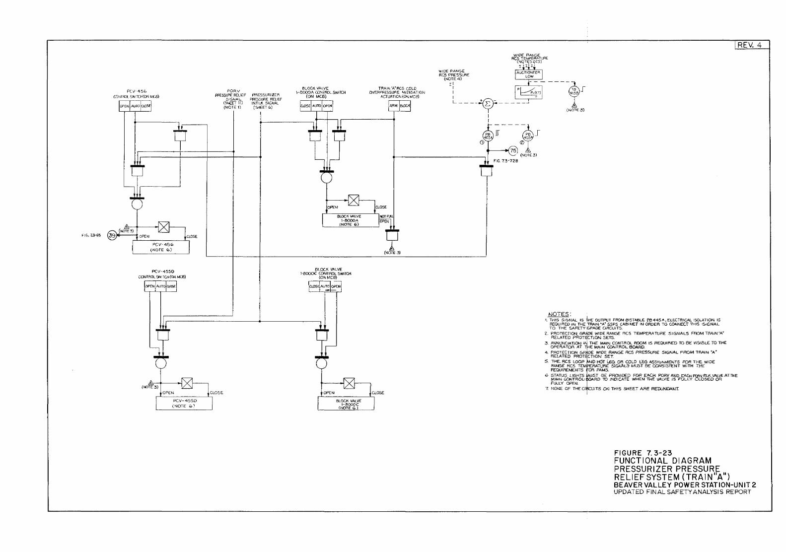
FIG. 7,3-65
PCV-45(. CONTROl SWITCH (ON M::8)
PCVC45<0 (NOTE <0)
PCV-4550 CONTROL SWITCH (ON MC8)
PORV Pf\E55URE P.EU EF
5~GNAL (SHEET 11) {NOTE 1)
PAESSURIZEF\ PRESSURE RELIEF INTU\ SIGNAL (SilEET 0)
BLOCK VALVE 1-8000A CONTROL SWITCH
(ON MCB)
BLOCK ""'LVE 1-80()()A
(NOTE 6)
BLOCK VALVE 1-BOOOC CONTROL SWITCH
(ONMGB)
OPEN
BLOCK VALVE 1-8000C
(NJTE <0)
TRAIN'A'RCS GCLD DVERP~ESSURE MITIGATIO,<J
ACTUATION (O>J MGB)
WIDE PANG£ RCS PRESSURE
REV. 4
(~T1E4) ~-----~ I p T5 J : ~T) 4138 L----v------
§----~5 _f 40
0 t------+1 75
(NOT£ 3) FIG. 7.3-729
(NOTE:3)
1-JOTES: '· THIS SIGNAL 15 iHE OUTP!JT FROM 815Tl\BLE E'fl 445A, ELECTRICl\L ISOLATION IS
REQ!JIRED IN THE TRAIN "A' SSPS GABINET IN ORDER TO CONNECT Tl-115 ·SIGNAL TO THE SAFETY GRADE CJACUITS.
2.. PROTECTION GRJioE WIDE RANGE RCS TEMPEAATLAE SIGNALS FROM TRAIN"A" RELATED PROTE!CTION SETS.
3. MJNUNCIATIOt-.1 u.j THE MAIN CONTROl.. ROOM IS REQUIRED TO BE VISIBLE TO THE OPERATOR AT r[HE MAIN 'CONTROL BOARO.
4. PROTECTION 6R~·OE WIDE RANGE RCS PRESSURE SlGNAL FROM TRAIN "A• RELATED PROT CTION SET.
5. rl-IE. RCS LOOP t-JU H6T LEG OR COLD l£6 ASSIC:>NMENTS FOR THE WIDE R4~E RCS TE!MRATLJAE SIGNAL!t MUST BE CONSISTENT WITH THE REQUIREMENTS Ofl PAMS.
6 STATUS LIGHTS UST ·BE PROVIDED FOR EACH PORV AND EACH FQRV ELK. 1/ALV£ AT TilE MAIN fDNTAOL- RO 10 INDICATE WHEN THE WllVE IS FULLY CLOSED OR FULLY OPE/J.
7. NOl-lE OF THE C UITS ON THIS SHEET ARE REDUNDANT i
FIGURE 7. 3-23 FUNCTIONAL DIAGRAM PRESSURIZER PRESSURE RELIEF SYSTEM (TRAIN 11 A11
)
BEAVER VAL LEY POWER STAT I ON-UN IT 2 UPDATED FINAL SAFETY ANALYSIS REPORT
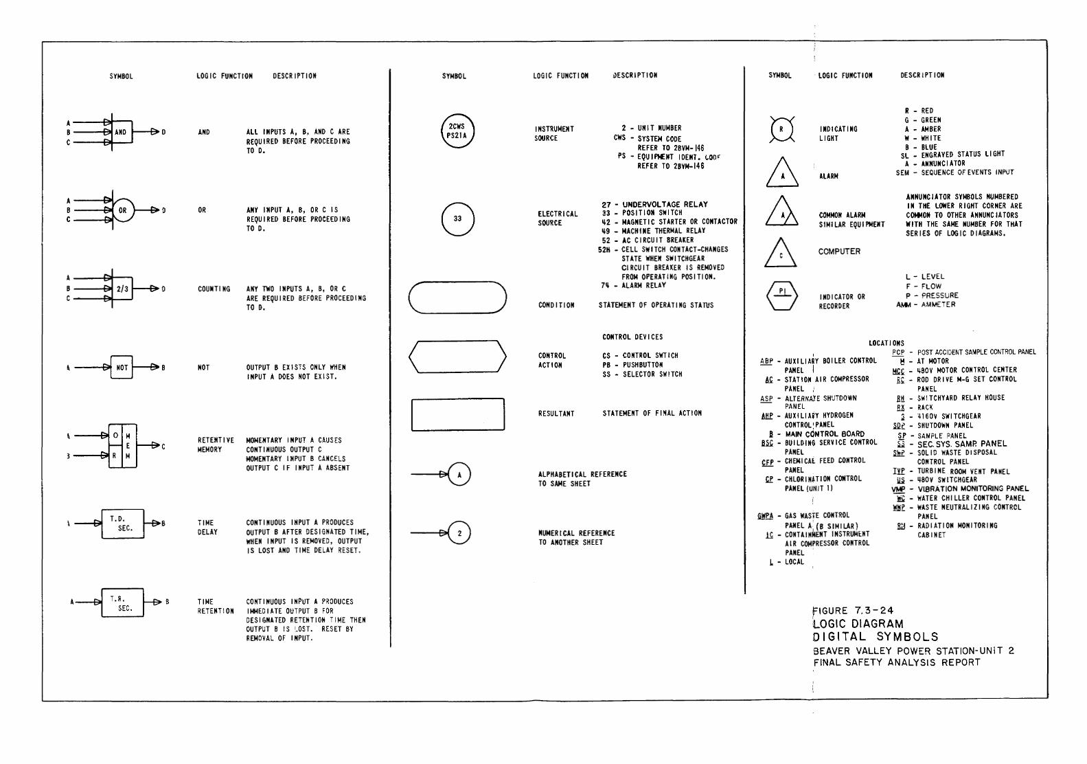
:
'
SYMBOL LOGIC FUNCTION OESCR IPT I OM SYMBOL LOGIC FUNCTION uESCRIPTION SYMBOL LOGIC FUNCTION DESCRIPTION
R - RED - 0 G - GREEN A ~ AND l 2CWS INSTRUMENT 2 -UNIT NUMBER INDICATING A - AMBER - D B ~ r ..... AND ALL INPUTS A, B, AND C ARE PS21A SOURCE CWS - SYSTEM CODE LJGHT W -WHITE c ... REQUIRED BEFORE PROCEEDING
REFER TO 2BVM-146 B - BLUE TO D. PS -EQUIPMENT IDENT. L00' SL - ENGRAVED STATUS LIGHT
REFER TO 2BVM-146 8 A -ANNUNCIATOR ALARM SEM - SEQUENCE OF EVENTS INPUT
..... & ANNUNCIATOR SYMBOLS NUMBERED A
8 27- UNDERVOLTAGE RELAY IN THE LOWER RIGHT CORNER ARE B - OR D OR ANY INPUT A, B, OR C IS 33 - POSITION SWITCH COMMON TO OTHER ANNUNCIATORS ~ ELECTRICAL COMMON ALARM c ... REQUIRED BEFORE PROCEEDING SOURCE ~2 - MAGNETIC STARTER OR COIITACTOR SIMILAR EQUIPMENT WITH THE SAME HUMBER FOR THAT TO 0. ~9 - MACHINE THERMAL RELAY SERIES OF LOGIC DIAGRAMS. 52- AC CIRCUIT BREAKER A 52H - CELL SWITCH CONTACT-CHANGES COMPUTER
STATE WHEN SWITCHGEAR CIRCUIT BREAKER IS REMOVED
A - FROM OPERATING POSITION. L- LEVEL B ..... 2/3 1 - COUNTING ANY TWO INPUTS A, B, OR C c ) 7~ - ALARM RELAY § F - FLOW .... 0
P- PRESSURE c .... I ARE REQUIRED BEFORE PROCEEDING INDICATOR OR TO D. CONDITION STATEMENT OF OPERATING STATUS RECORDER AMM - AMMETER
CONTROL DEVICES LOCATIONS
< l CONTROL CS - CONTROL SWTICH I PCP - POST ACCIDENT SAMPLE CONTROL PANEL
~~B ACTION PB - PUSHBUTTON ABP- AUXILIARY BOILER CONTROL M - AT MOTOR NOT OUTPUT B EXISTS ONLY WHEN PANEL I Mkk - ~BOV MOTOR CONTROL CENTER
INPUT A DOES NOT EXIST. SS - SELECTOR SWITCH A& - STATION AIR COMPRESSOR lik- ROD DRIVE M-G SET CONTROL PANEL ,; PANEL
ASP - ALTERNAtE SHUTDOWN Rtt - SWITCHYARD RELAY HOUSE
I I PANEL !l.K - RACK RESULTANT STATEMENT OF FINAL ACTION Atlf- AUXILIAiY HYDROGEN 1 - ~160V SWITCHGEAR CONTROL'PANEL SQf - SHUTDOWN PANEL
a - MAIN CONTROL BOARD \ ... 0 M SP - SAMPLE PANEL ... ~c
RETENTIVE MOMENTARY INPUT A CAUSES ~- BUILDING SERVICE CONTROL ~ - SEC. SYS. SAMP. PANEL 1-- E MEMORY CONTINUOUS OUTPUT C PANEL Shf - SOLID WASTE DISPOSAL .... 3 .... R M MOMENTARY INPUT B CANCELS CFP - CHEMICAl FEED CONTROL CONTROL PANEL OUTPUT C IF INPUT A ABSENT
~ ALPHABETICAL REFERENCE PANEL !YP - TURBINE ROOM VENT PANEL kf - CHLORIN~TION CONTROL ~ - ~80V SWITCHGEAR TO SAME SHEET PANEL (UNIT 1) VPif' - VIBRATION MONITORING PANEL
! !k- WATER CHILLER CONTROL PANEL Whr - WASTE NEUTRAliZING CONTROL , T.D. ~·
~fA - GAS WASTE CONTROL PANEL I TIME CONTINUOUS INPUT A PRODUCES
~ PANEL A. {B SIMILAR) ~ - RADIATION MONITORING SEC. DELAY OUTPUT B AFTER DESIGNATED TIME, NUMERICAL REFERENCE ~ - CONTAINMENT INSTRUMENT CAB I NET
WHEN INPUT IS REMOVED, OUTPUT TO ANOTHER SHEET AIR COMPRESSOR CONTROL IS LOST AND TIME DELAY RESET. PANEL
L - LOCAL I
·~· TIME CONTINUOUS INPUT A PRODUCES 7.3-24 SEC. RETENTION IMMEDIATE OUTPUT B FOR ~IGURE
i DESIGNATED RETENTION TIME THEN LOGIC DIAGRAM OUTPUT B IS ~OST. RESET BY DIGITAL SYMBOLS REMOVAL OF INPUT. BEAVER VALLEY POWER STATION-UNIT 2 FINAL SAFETY ANALYSIS REPORT
'·
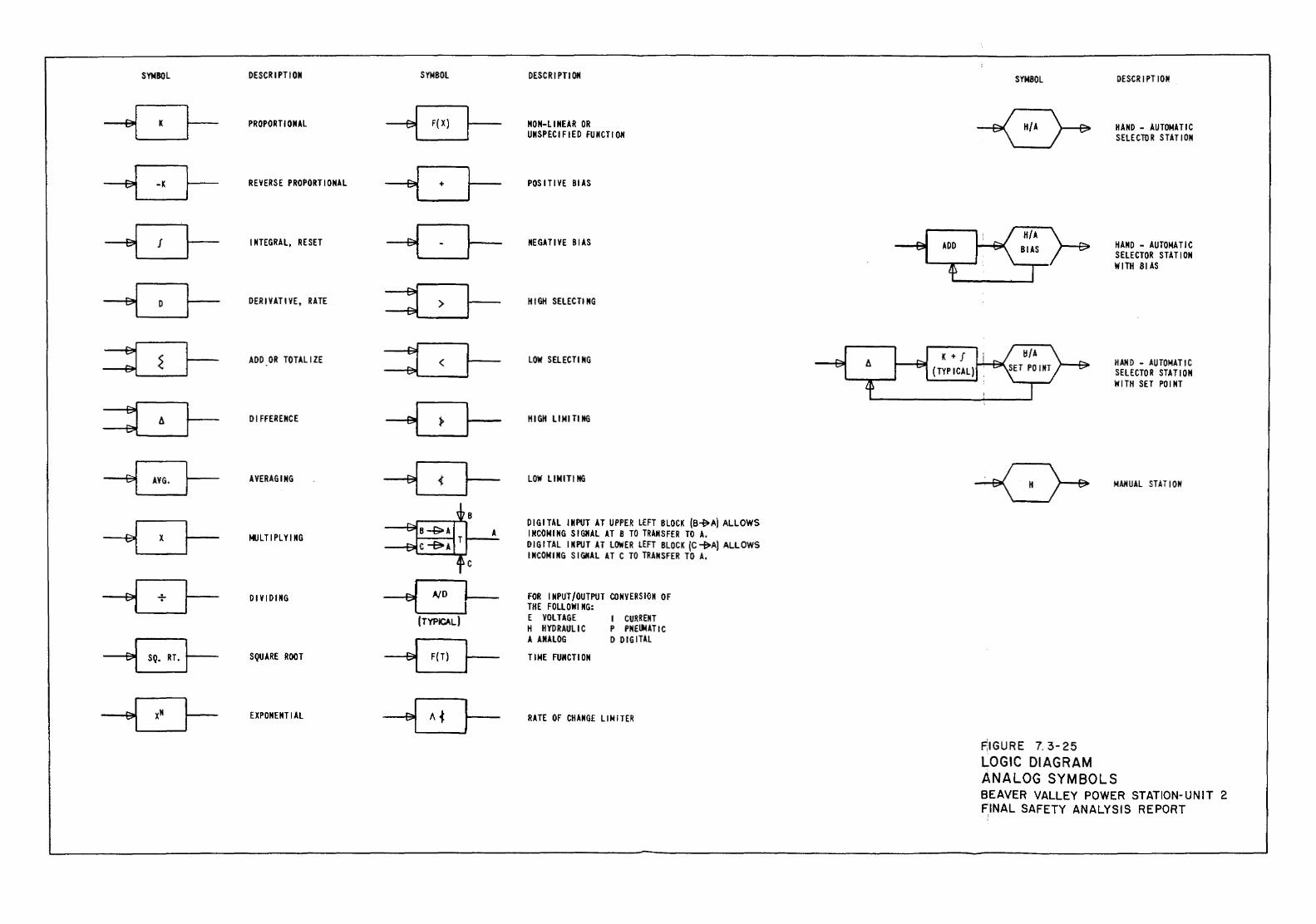
SYMBOL DESCRIPTION SYMBOL
-G- PROPORTIONAL
-G- REVERSE PROPORTIONAL
-G- INTEGRAL, RESET
--G- DERIVATIVE, RATE
=LJ- ADD OR TOTALIZE
~ Dt FFERENCE
---8-- AVERAGING
-G- MULTIPLYING
-G- DIVIDING -B-(TYPICAL)
~ SQUARE ROOT
-o- EXPONENTIAL
DESCR I PTt ON
NON-LINEAR OR UNSPECIFIED FUNCTION
POS ITt VE Bl AS
NEGATIVE BIAS
HIGH SELEC Tl NG
LOW SELECTING
HIGH LIMITING
LOW LIMIT! NG
DIG I TAL IN PUT AT UPPER LEFT BLOCK (B~ A) ALLOWS INCOMING SIGNAL AT 8 TO TRANSFER TO A. DIG I TAL I N PUT AT LOWER LEFT BLOCK {C ~A) ALLOWS INCOMING SIGNAL AT C TO TRANSFER TO A.
FOR INPUT/OUTPUT CONVERSION OF THE FOLLOW! NG: E VOLTAGE H HYDRAULIC A ANALOG TIME FUNCTION
I CURRENT P PNEII4ATI C D DIGITAL
RATE OF CHANGE LIMITER
ADD
K + J (TYPICAL)
SYMBOL DESCRIPTION
HAND - AUTOMATIC SELECTOR STATION
HAND - AUTOMATIC SELECTOR STATION WITH 81 AS
HAHD - AUTOMATIC SELECTOR STATION WITH SET PO I NT
MAHUAL STAT I 011
~IGURE 7. 3-25 LOGIC DIAGRAM ANALOG SYMBOLS BEAVER VALLEY POWER STATION-UNIT 2 FINAL SAFETY ANALYSIS REPORT
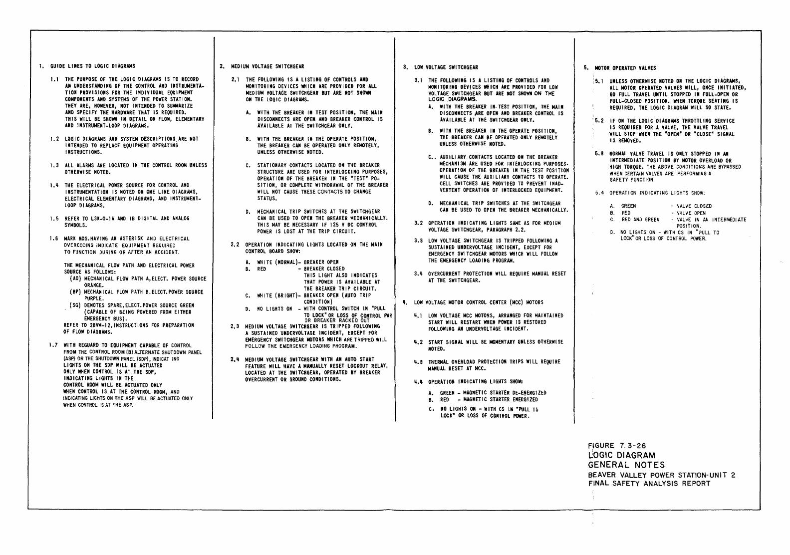
I. GUIDE LIMES TO LOGIC DIAGRAMS 2. MEDIUM VOLTAGE SWITCHGEAR
1.1 THE PURPOSE OF THE LOGIC DIAGRAMS IS TO RECORD 2. I THE FOLLOWING IS A LISTING OF CONTROLS AND AM UNDERSTANDING OF THE CO~TROL AND 1MSTRUMENTA- MONITORING DEVICES WHICH ARE PROVIDED FOR ALL TID~ PROVISIONS FOR THE INDIVIDUAL EQUIPMENT MEDIUM VOLTAGE SWITCHGEAR BUT ARE MOT SHOWN COMPONENTS AMD SYSTEMS OF THE POWER STATION. OM THE LOGIC DIAGRAMS. THEY ARE, HOWEVER, MOT INTENDED TO SUMMARIZE AND SPECIFY THE HARDWARE THAT IS REQUIRED. A. WITH THE BREAKER IN TEST POSITION, THE MAIM THIS WILL BE SHOWN IN D~TAIL ON FLOW, ELEMENTARY DISCONNECTS ARE OPEN AND BREAKER CONTROL IS AND INSTRUMENT-LOOP DIAGRAMS. AVAILABLE AT THE SWITCHGEAR ONLY.
1.2 LOGIC DIAGRAMS AND SYSTEM DESCRIPTIONS_ARE NOT B. WITH THE BREAKER IN THE OPERATE POSITION, INTENDED TO REPLACE EQUIPMENT OPERATING THE BREAKER CAM BE OPERATED ONLY REMOTELY, INSTRUCTIONS. UNLESS OTHERWISE NOTED.
1.3 ALL ALARMS ARE LOCATED IN THE CONTROL ROOM UNLESS c. STATIONARY CONTACTS LOCATED OM THE BREAKER OTHERWISE NOTED. STRUCTURE ARE USED FOR INTERLOCKING PURPOSES,
OPERATION OF THE BREAKER IN THE "TEST" PO-1.~ THE ELECTRICAL POWER SOURCE FOR CONTROL AHD SITIOM, OR COMPLETE WITHDRAWAL OF THE BREAKER
INSTRUMENTATION IS NOTED OM ONE LINE DIAGRAMS, WILL NOT CAUSE THESE CONTACTS TO CHANGE ELECTRICAL ELEMENTARY DIAGRAMS, AND INSTRUMENT- STATUS. LOOP D I AGRAMS.
D. MECHANICAL TRIP SWITCHES AT THE SWITCHGEAR 1.5 REFER TO LSK-0-IA AND 1B DIGITAL AND ANALOG CAN BE USED TO OPEl THE BREAKER MECHANICALLY.
SYMBOLS. THIS MAY BE NECESSARY IF 125 V DC CONTROL POWER IS LOST AT THE TRIP CIRCUIT.
1.6 MARK NOS.HAVING AM ASTERISK AND ELECTRICAL O'IERCODING INDICATE EQUIPMENT REQUIRED 2,2 OPERATION INDICATING LIGHTS LOCATED ON THE MAIM TO FUNCTION DURING OR AFTER AN ACCIDENT. CONTROL BOARD SHOW:
A. WHITE (NORMAL)- BREAKER OPEN THE MECHANICAL FLOW PATH AND ELECTRICAL POWER B. RED - BREAKER CLOSED SOURCE AS FOLLOWS: THIS LIGHT ALSO INDICATES {AD) MECHANICAL FLOW PATH A,ELECT~ POWER SOURCE THAT POWER IS AVAILABLE AT ORANGE. THE BREAKER TRIP CIRCUIT. (BP) MECHANICAL FLOW PATH B,ELECT.POWER SOURCE c. WHITE (BRIGHT}- BREAKER OPEN (AUTO TRIP PURPLE. COMO IT I OM} (SG) DEMOTES SPARE,ELECT.POWER SOURCE GREEN D. NO Ll GHTS ON - WITH CONTROL SWITCH IN ~PULL (CAPABLE OF BEING POWERED FROM EITHER TO LOCK~ OR LOSS OF CONTROL PWR EMERGENCY BUS}. OR BREAKER RACKED OUT REFER TO 2BVM-12,1MSTRUCTIONS FOR PREPARATION 2,3 MEDIUM VOLTAGE SWITCHGEAR IS TRIPPED FOLLOWING OF FLOW DIAGRAMS. A SUSTAINED UMDERVOLTAGE INCIDENT, EXCEPT FOR
EMERGENCY SWITCHGEAR MOTORS WHICH ARE TRIPPED WILL 1.7 WITH REGUARD TO EQUIPMENT CAPABLE OF CONTROL FOLLOW THE EMERGENCY LOAOI NG PROGRAM.
FROM THE CONTROL ROOM {B) ALTERNATE SHUTDOWN PANEL {ASP) OR THE SHUTDOWN PANEL (SOP), IND!CAT I NG 2.11 MEDIUM VOLTAGE SWITCHGEAR WITH AM AUTO START LIGHTS ON THE SOP WILL BE ACTUATED FEATURE WILL HAVE A MANUALLY RESET LOCKOUT RELAY, ONLY WHEN CONTROL IS AT THE SOP, LOCATED AT THE SWITCHGEAR, OPERATED BY BREAKER INDICATING LIGHTS IN THE OVERCURREMT OR GROUND CONDITIONS. CONTROL ROOM WILL BE ACTUATED ONLY WHEN CONTROL IS AT THE CONTROL ROOM, AND INDlCAT!NG LIGHTS ON THE ASP WILL BE ACTUATED ONLY WHEN CONTROL IS AT THE ASP.
3. LOW VOLTAGE SWITCHGEAR
3. I THE FOLLO~IMG IS A LISTING OF CONTROLS AND MOMITQRIMG DEV!CES WHICH ARE PROVIDED FOR LOW VOLTAGE SWITCHGEAR BUT ARE !tOT SHOWII ON THE LOGIC DIAGRAMS. A. WITH THE BREAKER IN- TEST POSITION, THE MAIM
DISCONNECTS ~REOPEN AM~ BREAKER CONTROL IS AVAILABLE AT THE SWITCHGEAR ONLY.
B. WITH THE BREAKER IN THE OPERATE POSITION, THE BREAKER CAN BE OPERATED ONLY REMOTELY UNLESS OTHERWISE NOTED.
c .. AUXILIARY CONTACTS LOCATED OM THE BREAKER MECHANISM ARE USED FOR INTERLOCKING PURPOSES. OPERATION OF THE BREAKER IN THE TEST POSITION WILL CAUSE THE AUXILIARY CONTACTS TO OPERATE. CELL SWITCHES ARE PROVIDED TO PREVENT INAD-VERTEMT OPERATIO~ OF INTERLOCKED EQUIPMENT.
D. MECHANICAL TRIP SWITCHES AT THE SWITCHGEAR CAM BE USED TO OPEN THE BREAKER MECHANICALLY.
3.2 OPERATION INDICATING LIGHTS SAME AS FOR MEDIUM VOLTAGE SWITCHGEAR, PARAGRAPH 2.2.
3.S LOW VOLTAGE SWITCHGEAR IS TRIPPED FOLLOWING A SUSTAINED UNDERVOLTAGE INCIDENT, EXCEPT FOR EMERGENCY SWITCHGEAR MOTORS WHICH WILL FOLLOW THE EMERGENCY LOADING PROGRAM.
3.~ OVERCURRENT PROTECTION WILL REQUIRE MANUAL RESET AT THE SWITCHGEAR.
~. LOW VOLTAGE MOTOR CONTROL CENTER (MCC) MOTORS
ll.l LOW VOLTAGE MCC MOTORS, ARRANGED FOR MAINTAINED START WILL RESTART WHEN POWER IS RESTORED FOLLOWING AN UNDERVOLTAGE INCIDENT.
~.2 START SIGNAL WILL BE MOMENTARY UNLESS OTHERWISE NOTED.
~.9 THERMAL OVERLOAD PROTECTION TRIPS WILL REQUIRE MANUAL RESET AT MCC.
~-~ OPERATION INDICATING LIGHTS SHOW:
A. GREEN- MAGNETIC STARTER DE-E~ERGIZED B. RED - MAGNETIC STARTER ENERGIZED c. NO LIGHTS ON -WITH CS IN •PULL TO
LOCK• OR LOSS OF CONTROL POWER.
5. MOTOR OPERATEO VALVES
i 5.1 UNLESS OTHERWISE NOTED OM THE LOGIC DIAGRAMS, All MOTOR OPERATED VALVES WILL, ONCE INITIATED, GO FULL TRAVEL UNTIL STOPPED IN FULL-OPEN OR FULL-CLOSED POSITION. WHEN TORQUE SEATING IS REQUIRED, THE LOGIC DIAGRAM WILL SO STATE.
'5.2 IF OM THE LOGIC DIAGRAMS THROTTLING SERVICE IS REQUIRED FOR A VALVE, THE VALVE TRAVEL WILL STOP WHEN THE ~OPEN~ OR "CLOSE" SIGNAL IS REMOVED.
s.a NORMAL VALVE TRAVEL IS ONLY STOPPED IN AM INTERMEDIATE POSITION BY MOTOR OVERLOAD OR HIGH TORQUE. THE ABOVE CONDITIONS ARE BYPASSED WHEN CERTAIN VALVES ARE PERFORMING A SAFETY FUNCTION
5.4 OPERATION INDICATING L1 GHTS SHOW:
A. GREEN - VALVE CLOSED B. RED - VALVE OPEN C. RED AND GREEN - VALVE IN AN INTERMEDIATE
POSITION. D. NO Ll GHTS ON - WITH CS IN "PULL TO
LOCK" OR LOSS OF CONTROL POWER.
FiGURE 7. 3-26 ~OGIC DIAGRAM GENERAL NOTES BEAVER VALLEY POWER STATION-UNIT 2 FINAL SAFETY ANALYSIS REPORT
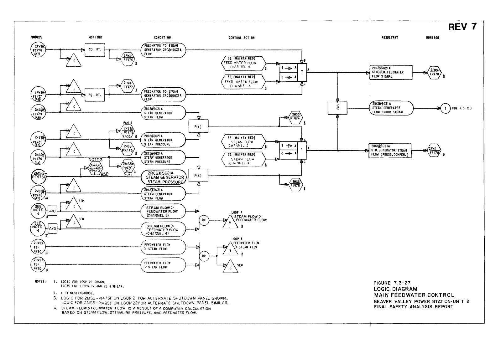
MOTES:
MCIU TOR
~9SQ
1. LOGIC FOR LOOP 21 SHOWN, LOGIC FO~ LOOI'S 22 00 23 S lM I LAR,
2. # BY WESTINGHOUSE.
COIIO!TI OM
FEEOWATER TO STEAM GENERATOR 2R~SG21 A FLOW
FEEDWATER TO SJEAM GENERATOR 2RC~G21A FLOW
2RC~G21A \_STEAM GENERATOR
STEAM FLOW
2RC~G21A STEAM GEMER!TOR STEAM PRESSURE
2RC~G2lA STE GENERATOR STEAM PRESSURE
2RCS*SG21A STEAM GENERATOR STEAM PRESSUR
2RC~G21A STEAM GENERATOR STEAM FLOW
STEAM FLOW>
\, FEEOWATER FLOW {CHANNEL 3)
STEAM FLOW> FEEOWATER FLOW {CHANNEL 4)
FEEDWATER FLOW ) STEAM FLOW
FEEDWATER FLOW .) STEAM FLOW
F (X)
CONTROL ACTION
SS. MAl NT.\ I NED) FEtD WATER FLCW
CHANNEL 3
SS (MAINTAIKED) STEAM FLOW
(H.Il,NNEL 3
SS (MAINTAINED) SfEAIA FLOW
CHAt\INEL 4
LOOP • STEAM FLOW) FEEDWATER FLOW
I
3. LOGIC fOR 2M5S-P1475F ON LOOP 21 FOR ALTERNATE SHUTDOWN PANEL SHOWN. LOG !C FOR 2M S5- P!485F ON LOOP 22 FOR All ERN ATE SHUTDOWN PANEL S 1M ll.AR.
4. STEAM FLOW>FEEDWtHER FLOW IS A RESULT OF A COMPUTER CAl..CULATlQN BASED ON STEAM FLOW, STEAMLINE PRESSURE, AND FEEOWATER FLOW.
B
RESULTANT
2RC*GlU .------.....-----f"JJ STM;GIM. FEEDWATEfl FLOW SIGNAL
RC~G21A 1------{11 STE1iM GENERATOR
FLOW ERROR SIGNAL
2RC$Q21A r:-----~ ....... ----~:. STM.uEHERATOit_ STEA!-4
,FLOW (PRESS.COMPEN.)
FIGURE 7. 3-27 LOGIC DIAGRAM
REV 7 r«<MITOif
I
FIG. 7.3-28
.B:
MAIN FEEDWATER CONTROL BEAVER VALLEY POWER STATION-UNIT 2 FINAL SAFETY ANALYSIS REPORT
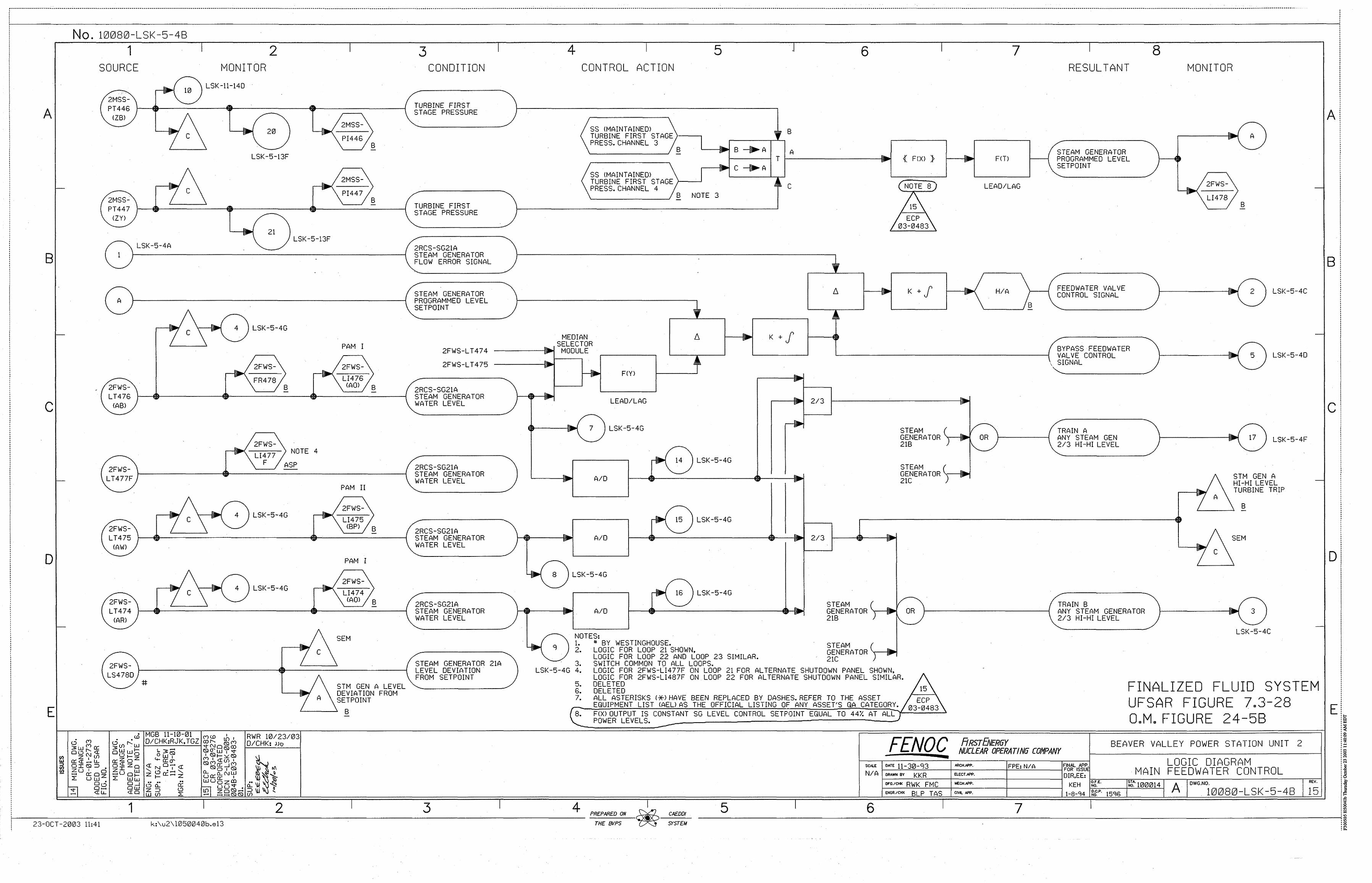
A
B
c
D
No. 10080-LSK-5-48 1
SOURCE
2MSS-PT447
<ZYl
-( 1
r A
2FWS-LT476
<ABl
2FWS-LT477F
LSK-5-4A
10
c
c
2 MONITOR
LSK-11-140
4
/
20
LSK-5-13F
21 LSK -5-13F
LSK-5-4G
2FWS-
FR478
2FWS-LI477
F
B
NOTE 4
ASP
2FWS-LT475
CAWl
C ~ ..._4___. l LSK-5-4G
2FWS-LT474
CAR>
2FWS-LS478D
c 4 ) LSK-5-4G
-
c
2MSS-
2MSS-
PAM I
2FWS-LI476
B
B
<AOl B
PAM II
2FWS-LI475
<BPl
PAM I
2FWS-LI474
<AOl
SEM
B
B
3 CONDITION
TURBINE FIRST STAGE PRESSURE
TURBINE FIRST STAGE PRESSURE
2RCS-SG21A STEAM GENERATOR FLOW ERROR SIGNAL
STEAM GENERATOR PROGRAMMED LEVEL SETPOINT
4 CONTROL ACTION
SS CMAINTAINEDl TURBINE FIRST STAGE>---. PRESS.CHANNEL 3
B
SS <MAINTAINEDl TURBINE FIRST STAGE >-~-~ PRESS.CHANNEL 4
5
B NOTE 3
6 7
B
8 ,. A A r---~ T r------------------ { F<Xl } F<Tl
C 1\111 A
c LEAD/LAG
~---· K + f H/A
'------~B
~----· K +j 2FWS-L T474
2FWS-LT475
MEDIAN --SELECTOR
------- MODULE
2RCS-SG21A STEAM GENERATOR WATER LEVEL
2RCS-SG21A STEAM GENERATOR WATER LEVEL
2RCS-SG21A STEAM GENERATOR WATER LEVEL
2RCS-SG21A STEAM GENERATOR WATER LEVEL
STEAM GENERATOR 21A LEVEL DEVIATION. FROM SETPOINT
...
'----·
.... ... F<Yl
LEAD/LAG
7 LSK-5-4G
t
14 ) LSK-5-4G
,----· ... ,..
A/D 1------@11-----------------------1 f----· ~ 15 LSK-5-4G
2/3 r-----~-------·
STEAM ( / ~ GENERATOR y • OR }1---------j 21B I " ..____,
STEAM s GENERATOR ~ 21C
r-.1-------· A/0 r-~~----------------~~-· 2/3
LSK-5-4G
... ... 16 LSK-5-4G
t---.1-------· A/0 r-~--------------~~
. / -.{'l
NOTES: 1. " BY WESTINGHOUSE. 2. LOGIC FOR LOOP 21 SHOWN,
LOGIC FOR LOOP 22 AND LOOP 23 SIMILAR. 3. SWITCH COMMON TO ALL LOOPS.
STEAM ( / GENERATOR~ OR 218 ) - ,...___,
~~~~~A TOR ("--1--~ 21C J --
LSK-5-4G 4. LOGIC FOR 2FWS-LI477F ON LOOP 21 FOR ALTERNATE SHUTDOWN PANEL SHOWN, LOGIC FOR 2FWS-LI487F ON LOOP 22 FOR ALTERNATE SHUTDOWN PANEL SIMILAR.
RESULTANT
STEAM GENERATOR PROGRAMMED LEVEL SETPOINT
FEEDWATER VALVE CONTROL SIGNAL
BYPASS FEEDWATER VALVE CONTROL
, SIGNAL
TRAIN A ANY STEAM GEN 213 HI -HI LEVEL
TRAIN B ANY STEAM GENERATOR 2/3 HI-HI LEVEL
8 MONITOR
2FWS-
LI478
A
B
1---------~ 2 I LSK-5-4C
-
!--------~ 5 ) LSK-5-40
-
1---------.( 17 ) LSK-5-4F
A
c
STM GEN A HI-HI LEVEL TURBINE TRIP
B
SEM
f------.( 3
LSK-5-4C
STM GEN A LEVEL 5• g~tn~g FINALIZED FLUID sYsTEM ~g~~1~~N FROM ~: ALL ASTERISKS (*)HAVE BEEN REPLACED BY DASHES.REFER TO THE ASSET UFSAR FIGURE 7 3 28
E EQUIPMENT LIST CAEU AS THE OFFICIAL LISTING OF ANY ASSET'S QA CATEGORY. . . • -
~r-~-~--~~\TI~Hm~~~~~~~~~~----B-------------------~8~.~~~b~~~~~~~i;P~~J~EL;I~~-~C~O~NS~T=A=N=T=S=G==LE=V=E=L=C=O=N=TR=O=L==SE=T=P=O=IN=T==EQ=U=A=L=T=0==4~4%:.:A:T:A:L:L~~~====~~~~~==~==~======T=====~Q~.M~.~F~~I~G~U~R~E~==2~4~~5~8~========~ ill MGB 11-10-01 (")U) I RWR 10/23/03
~Ul r-:w 0/CHK:RJK,TGZ ~~0~~ D/CHK: ,Jf.1
0ww~ ~3- ISI~w~~ o~o owo:p 1 ISif-Y:ISI
~zoz ~~~ (")I~Ull 0~ Zo ~ N O'j ~ ISI~~_J~ t/1 zi w ' o ....... ' o.. o I ~u 0~ z 1- ~- z UO::O..o::NlJ-1 ..,g_ Z ww ~ o , .. .. .. WUozal •• . N ow 0 o.. o:: uu~ . o.. ~ ~
~ 0 z ::J o m z oiSI ...... ::J I)) , W (J) :::2: ...-a - ......,.. lSI IS) (f)
5
FENOC SCAlE DATE ll-31ZJ-'J3 N/A ORAWN BY KKR
OFG./CI« RWK FMc E•GR./CHK BLP TAS
6
ARSTfi.IER6Y BEAVER VALLEY POWER STATION UNIT 2 NUCLEAR OPERATIN6 COMPANY
FINAl M'P. LOGIC DIAGRAM FOR ISSU . MAIN FEEDWATER CONTROL D!R,EE: io.-;;-------,-,,.------,----.-=:=-:c::-------------------,-=--!
KEH ~.E. ~~ .. 100014 A DWG NO REV.
1-a-<)4 '""'(}g;:.;,:"--1-5<)-6--rc....:..:e:=-'--~ . i 0 0 8 0-L S K-5-4 B 15
ARCH.-. FPE: N/A EL.ECT . .APP.
ME-CH.APP.
CIVL f>PP.
7
A
B
c
0
i 9 f...-----------1 _____________ 2 _____________ 3 ____ --'---------4- PREPARED ON CAEDDI
SYSTEM ----------------------------------------------------------------------------------------------------------------------~~
23-0CT -2003 11:41 k:".u2\ l050040b.e13 THE ENP$ 8 li!
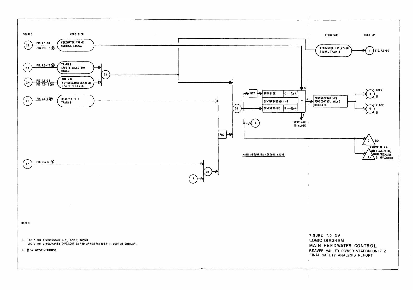
SOURCE
FIG. 7.3-28
FIG. 7.3-18@
FIG. 7.3-13 (i)
FIG. 7.3·10@
IIOTES:
COIID IT1 011
FEEOWATER YALYE COIITROL S I GliAL
TRAIII B SAFETY IIIJECTI 011 SIGIIAL
TRAIN 8 ANY STEAIII GENERATOR 2/3 HI-HI LEVEL
REACTOR TRIP TRAIII 8
J.. LOGIC FOR 2FWSXFCYii 78 (- Pl, LOOP 21 SHOWN LOGIC FOR 2FWSXFCY1i88 {· P ), LOOP 22 AND 2FWS*FCV498 (- P), LOOP 23 Sl N I LAR.
2. it BY WESTINGHOUSE
Ell ERG I ZE
2FW~SY1i78B (-pI
MAIM FEEOWATER COIITROL YALYE
RESUL TAIIT MOIUTOR
L--...t0EEOWATER I SOLA T 100\, __ r::/:\ \...._~ IGIIAL TRAIN B J ~ FIG. 7.3-30
c
T
YEIIT AIR TO CLOSE
2FW.CY1178 (-PI FlMCOMTROL VALVE MODULATE
FIGURE 7.3-29 LOGIC DIAGRAM MAIN FEEDWATER CONTROL BEAVER VALLEY POWER STATION-UNIT 2 FINAL SAFETY ANALYSIS REPORT
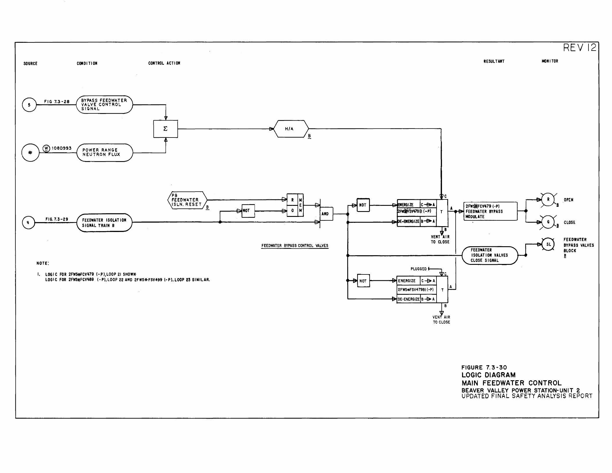
SOURCE
Fl G 7.3-28
1080993
FIG. 7.3-29
NOTE:
CONDITION
BYPASS FEEOWATER VALVE CONTROL SIGNAL
POWER RANGE N E U T R 0 N F L U.X
FEEDWATER ISOLATION SIGNAL TRAIN B
1. LOGIC FOR 2FW~CY,79 I-P ), LOOP 21 SHOWtt
CONTROL ACT I ON
PB FEEDWATER ISLN. RESET
LOGIC FOR 2FW$iEFCY~9 (·P),LOOP 22 AND 2FWS*FSV499 (-P),LOOP 23 SIMILAR.
H/A
R M t---1 E (---t=ill--~
---+ill NOT ~----+311 0 M AND
FEEDWATER BYPASS CONTROL VALVES
2FWS*FSV479BI (-P)
'-------"""B' DE -ENERGIZE B --9r> A
T
c
8
c
B
RESULTANT
2FW-CY~79 ( -P) t-A----Bit FEEOWATER BYPASS
MODULATE
A
FEEDWATER ISOLATION VALVES CLOSE SIGNAL
MOM I TOR
REV 12
OPEN
CLOSE:
FEEDWATER BYPASS VALVES BLOCIC ~
VEN AIR TO CLOSE
FIGURE 7. 3-30 LOGIC DIAGRAM MAIN FEEDWATER CONTROL BEAVER VALLEY POWER STATION- UNIT 2 UPDATED FINAL SAFETY ANALYSIS REPORT
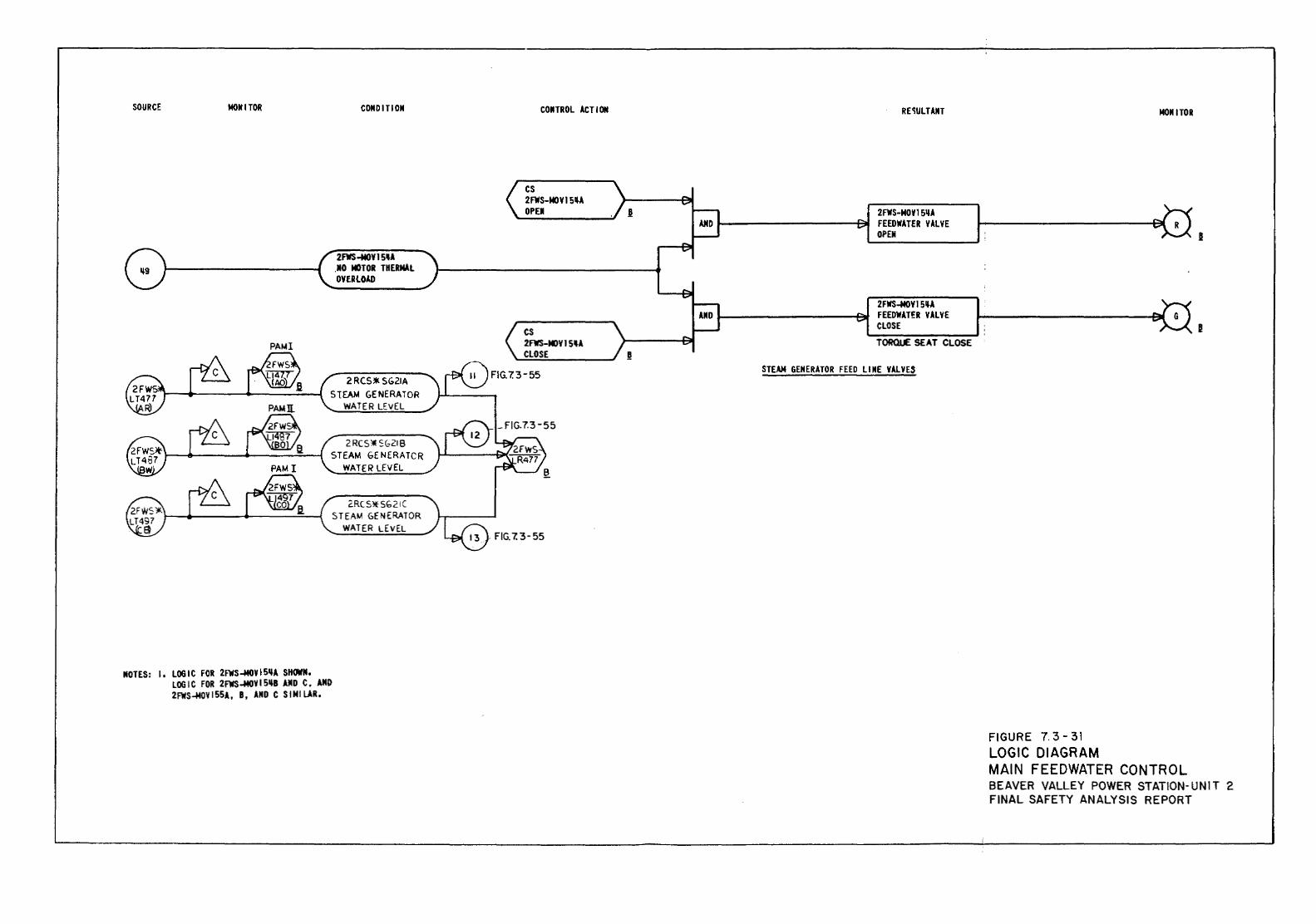
SOURCE MOM I TOR
PAtH
COIIDITIOII
2FWS-MOY ISU .JIO MOTOR THERMAL OYERlOI.D
2RCS*-SG21A StEAM GENERATOR
WATER LEVEL
2RC91:SG218 STEAM GENERATCR
WATER LEVEL
2.RCSltSG21C STEAM GENERATOR
WATER LEVEL
MOTES: 1. LOGIC FOR 2FWS-MOVI5~A SHOWII. LOGIC FOR 2FWS-MOVI5-B AMD C, AMD 2FWS-MOVI55A, B, AIID C SIMILAR,
CONTROL ACT I ON
cs 2FW5-MOVI5U DPEJI
cs 2FWS-MOY15U CLOSE
FIG.7.3-55
RE'!ULTAIIT
2FWS-NOVI511A FEEDWATER VALVE OPEII
2FWS-MOV15U FEEDWATER VALVE CLOSE TORQUE SEAT CLOSE
STEAM GENERATOR FEED LIME VALVES
FIGURE 7. 3-31 LOGIC DIAGRAM
MDIII TOR
MAIN FEEDWATER CONTROL BEAVER VALLEY POWER STATION-UNIT 2 FINAL SAFETY ANALYSIS REPORT
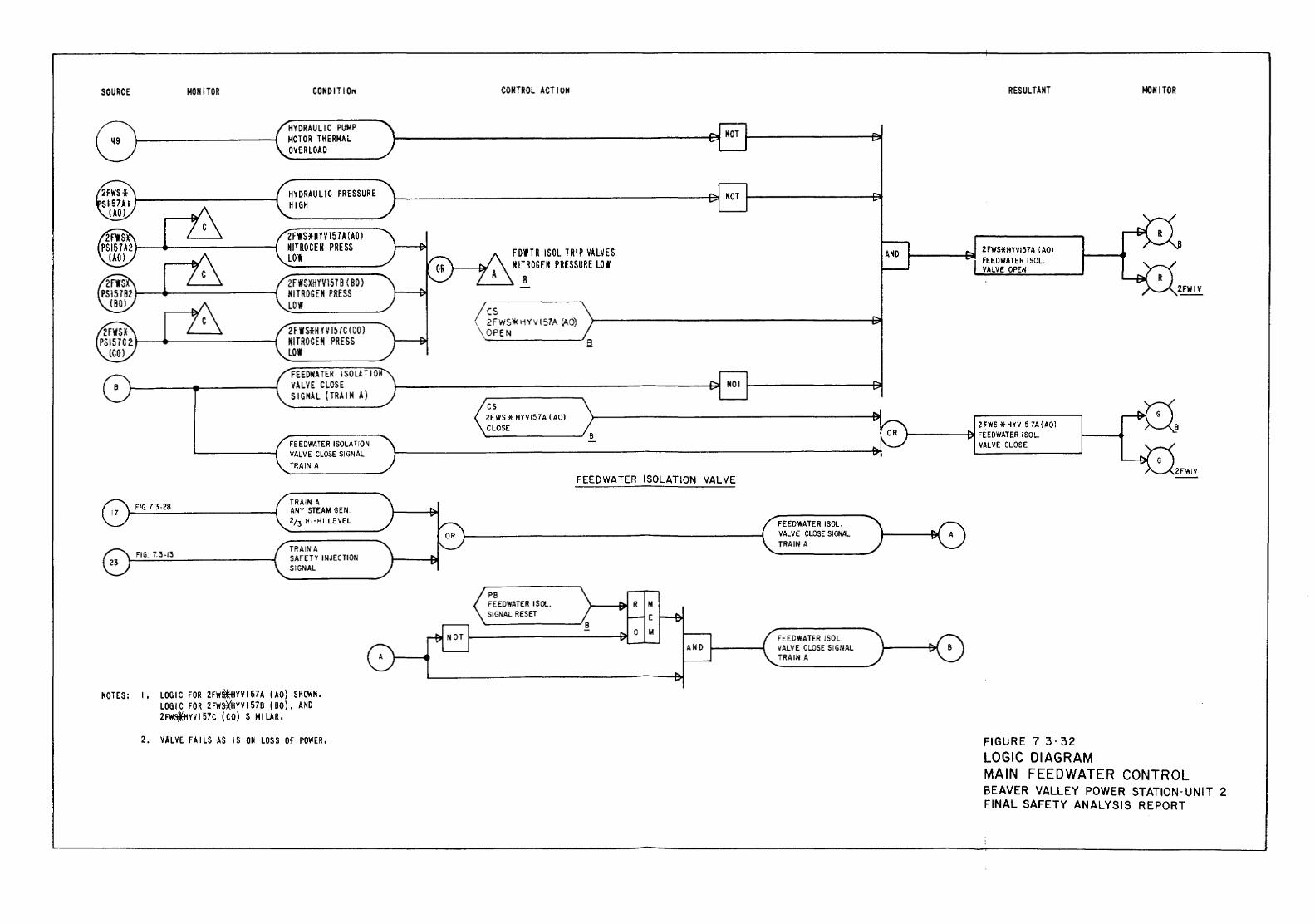
SOURCE MONITOR
FIG 7.3-28
FIG. 7. 3-13
CONDITIO"'
HYDRAULIC PUMP MOTOR THERMAL OVERLOAD
HYDRAULIC PRESSURE HIGH
2 F WS*II YV !57 A (AD) NITROGEN PRESS LOW
2FWS*HYV1578 ( BO) NITROGEN PRESS LOW
2FWS*H YV 157C (CO) NITROGEN PRESS LOW
FEEDWATER I SO LH I 01 VALVE CLOSE SIGNAL (TRAIN A)
FEEDWATER ISOLATION VALVE CLOSE SIGNAL TRAIN A
TRAIN A ANY STEAM GEN. 2;3 HI-HI LEVEL
TRAIN A SAFETY INJECTION SIGNAL
NOTES: I , LOGIC FOR 2FWs?ffiYV I 57 A ( AO) SHOWN, LOGIC FOR 2FW~YV157B (80), AND 2FW~YVI57C (CO) SIMILAR.
2. VALVE FAILS AS IS ON LOSS OF POWER,
CONTROL ACTION
F D'ITR I SOL TRIP VALVES N 1T ROG EM PRESSURE LO 'I
8
cs \ 2FWSO!kHYVI57A Vl-0)
OPEN ,_ _____ __,a
cs 2FWS * HYVI5 7A ( AO) CLOSE '---------' 8
PB FEEDWATER ISOL. SIGNAL RESET
FEEDWATER ISOLATION VALVE
FEEDWATER ISOL. VALVE CLOSE SIGNAL TRAIN A
FEEDWATER ISOL. VALVE CLOSE SIGNAL TRAIN A
RESULTANT
2 FWS * HYVI5 7A ( AOl J-------91 FEEDWATER I SOL.
VALVE CLOSE
FIGURE 7. 3-32 LOGIC DIAGRAM
MONITOR
MAIN FEEDWATER CONTROL BEAVER VALLEY POWER STATION-UNIT 2 FINAL SAFETY ANALYSIS REPORT
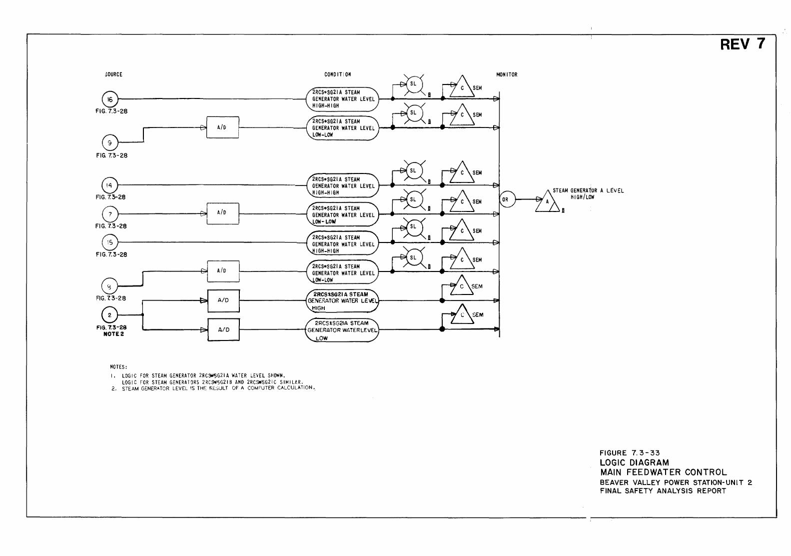
NOTES: I, LOGIC FOR STEAM GENERATOR 2RC~G21A WATER LEVEL SHOWN.
LOGIC FOR STEAM GENERATORS 2RC~G21B AND 2RC~G21C SIMIL~R. 2. STEAM GENERATOR LEVEL IS THE RE.SULT OF A COMPUTER CALCULATION •.
FIGURE 7. 3-33 LOGIC DIAGRAM
REV 7
MAIN FEEDWATER CONTROL BEAVER VALLEY POWER STATION-UNIT 2 FINAL SAFETY ANALYSIS REPORT
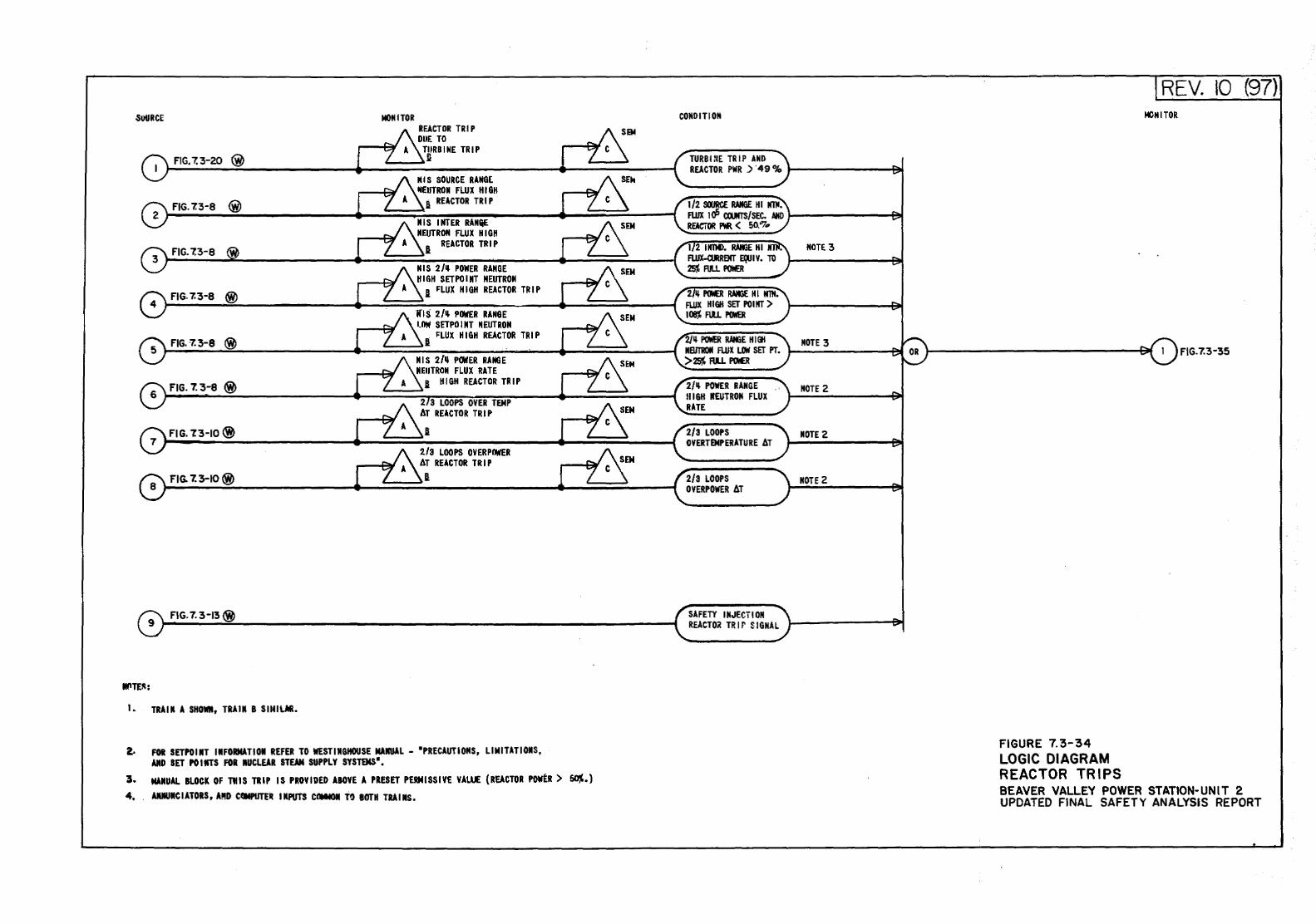
.SUURCE MONITOR REACTOR TRIP DUE TO
TIIRB I ME TRIP FIG. 7. 3-20 @ li
IU S SOURCE RANGL IIIEIITROII FlUX HIGH
FIG. 7.3-8 ® a REACTOR TRIP
IllS I HTER RAIIQE IIEUTROM FLUX HIGH
REACTOR TRIP FIG.7.3-8 I
3 IllS 2/~ POWER RANGE HIGH SETPOIIIT NEUTRON
FIG. 7.3-8 ® 1 FLUX HIGH REACTOR TRIP
lfiS 2/" PlrftER RANGE lOW SETPOIIIT NEUTRON
FIG.7.3-8 @> I FLUX HIGH REACTOR TRIP
IllS 2/" POWER RANGE IIEIITROII FLUX RATE
FIG. 7._ 3-8 @> I HIGH REACTOR TRIP 6
2 3 LOOPS OYER TEMP AT REACTOR TRIP
7 FIG. 'l3-IO @
2/3 LOOPS OYERPnwER AT REACTOR TRIP
FIG. 7. 3-10 @ I
FIG. 7. 3-13@
1. TRAIN A SHOWN, TRAIN B SINilAI.
2- FOR SETPO lilT IIIFORMATI 01 REFER TO WEST IIIGitOUSE MAIIUAL - •PRECAUT I OilS, Ll M I TAT I OilS, AID SET PO lilTS FOR NUCLEAR STEAM SUPPLY SYSltMS •.
3. MANUAL BLOCK OF ntiS TRIP IS PROVIDED ABOVE A PRESET PERMISSIVE VALUE (REACTOR POWER > ~.) 4. AIUIUIIC lA TORS, A!!D CCIMPUTE- INPUTS CaM«<II T~ BOTH ru I IllS.
CONDITION
1/2 SOORCE IWIGE HI IITit. FWX UP CCUfTS/SEC. AND REACiOR Nl < 50."7 ..
1 2 llfiM). !WEE HI Fl.IJX-a.llREMT E(Q I Y. 10 25j RILL PO'IER
2N I'(M(R ~WEE HI IITit. FLUX HIGH SET POINT) 108% Fill Pl7fi'ER
2N POWER RAMlE HHII IIBJTROII FLUX LOW SET PT. >25% R.U POe
2/" POWER RANGE IIIGH IIEUTROII FLUX RATE
SAFETY INJECTION REACTO~ TRir SIGNAL
NOTE 3
NOTE 3
MOTE 2
NOTE 2
IIOTE 2
FIGURE 7. 3-34 LOGIC DIAGRAM REACTOR TRIPS
REV . 10 MCNlTOR
F\G.7.3-35
(97)
BEAVER VALLEY POWER STATION-UNIT 2 UPDATED FINAL SAFETY ANALYSIS REPORT
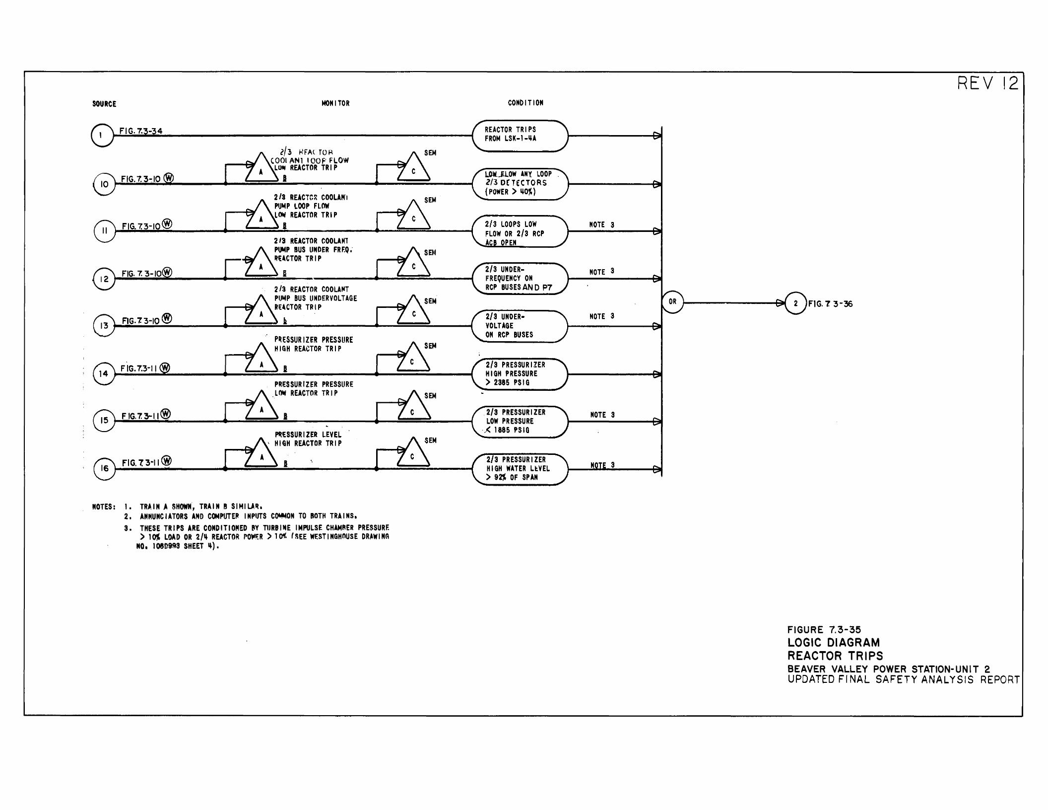
SOURCE MONITOR
FIG. 7.3-34
l/3 h'FACTOR (001 ANl I OOF' FLOW
LO- REACTOR TRIP FIG. 7. 3-:10 I
2/3 REACTC:\ COOLAffl PIJt.tP LOOP FLOW LOW REACTOR TRIP
FIG. 7.3-10@ I 213 REACTOR COOLAMl B ~p BUS UMDER FRF.Q. c ~~CTOR TRIP
0 FIG. 7. 3-IO@
2/3 REACTOR COOLA"T PUt.tP BUS LINDER VOLTAGE RUCTOR TIH P
FIG. 7. 3-10 @) ».
P~ESSURIZER PRESSURE HIGH REACTOR TRIP
FIG. 7.3-11 I PRESSURIZER PRESSURE L~ REACTOR TRIP
F IG. 7. 3-11@) I
,_ESSURIZER LEVEL , HIGH REACTOR TRIP
A FIG. 7. 3-11@ I
MOTES: 1. TRAIN A SHOWN, TRAIN 8 SIMILA~. 2. ANMUMCIATORS AND COMPUTE~ INPUTS C~OM TO ROTH TRAINS. 3. THESE TRIPS ARE COMO IT I OMED l'Y TIJRB I fiE IMPULSE CHAMAER PRESSURF.
) 1 ~ LOAD OR 2N REACTOR PO"'-:R ) 1 ()( ( ~EE WESTINGHOUSE DRAWl MA NO. 10809~3 SHEET~).
CONbiTIOM
REACTOR TRIPS FROM LSK ... l ... IJA
LOW~OW ANY lOOP Z/3 0£ TcCTORS (POWER ) IJO~)
2/3 LOOPS LOW FLOW OR 2/3 RCP A PEN
2/3 UNDER-FREQUENCY ON RCP BUSES AN 0 P7
2/3 UNDER-VOLTAGE ON RCP BUSES
2/3 PRESSURIZER HIGH PRESSURE ) 2385 PSIG
.2/3 PRESSURIZER LOW PRESSURE
· .. ( 188 5 P S I G
2/3 PRESSURIZER HIGH WATER L~VEL ) 9~ OF SPAN
NOTE 3
NOTE 3
NOTE 3
NOTE 3
2 FIG.?. 3-:36
FIGURE 7.3-3S LOGIC DIAGRAM REACTOR TRIPS
REV 12
BEAVER VALLEY POWER STATION-UNIT 2 UPDATED Fl NAL SAFETY ANALYSIS REPORT
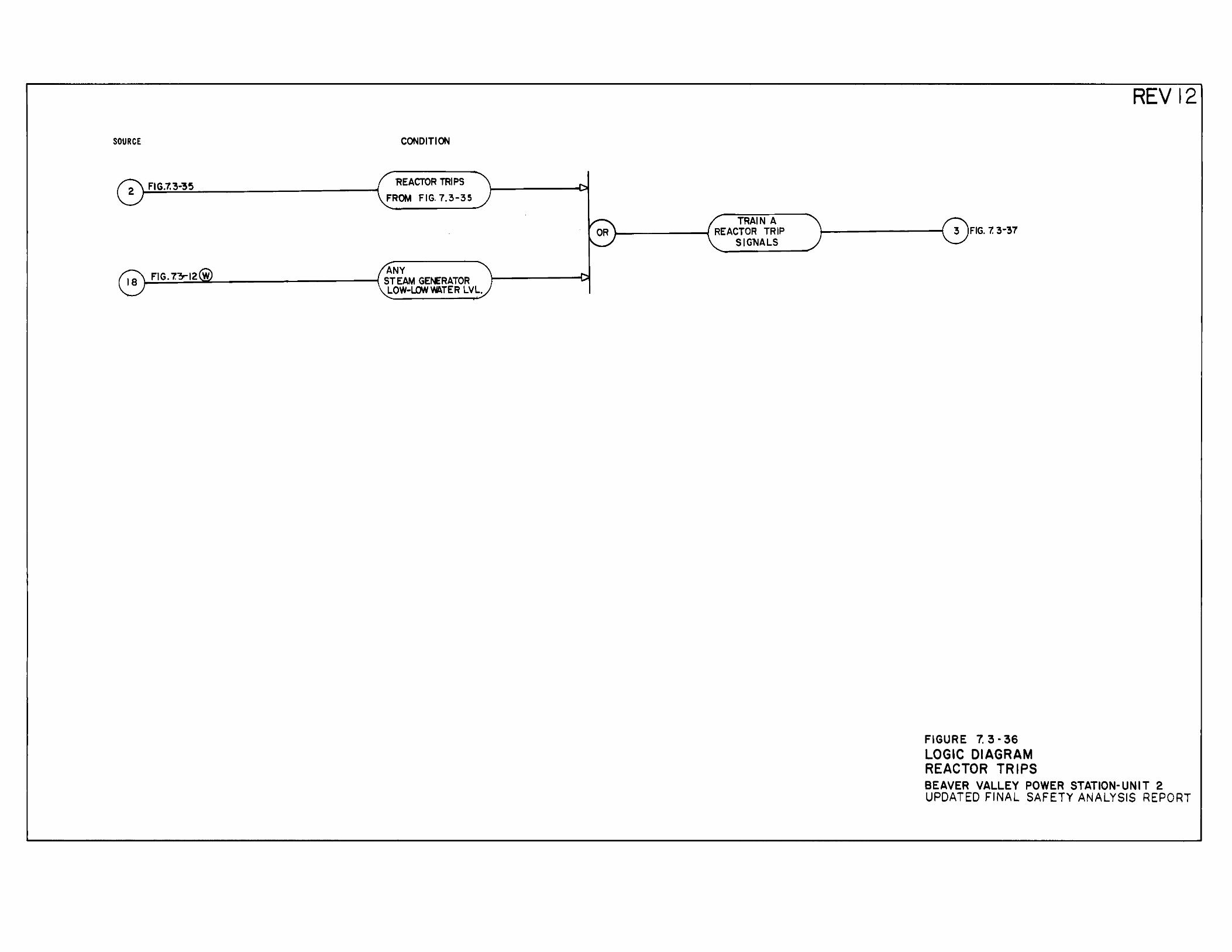
SOURCE CONDITION
'REACTOR TRIPS FROM FIG. 7.3-35
ANY ~:::.:....::.~~;.....__-----------1 STEAM GErERATOR
LOW·LOW WATER LVL.
TRAIN A J--------t REACTOR TRIP
SIGNALS
FIGURE 7. 3 • 36 LOGIC DIAGRAM REACTOR TRIPS
REV12
BEAVER VALLEY POWER STATION-UNIT 2 UPDATED FINAL SAFETY ANALYSIS REPORT
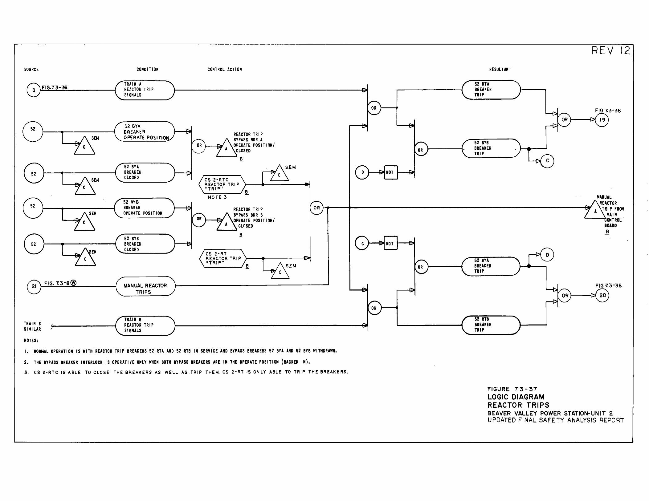
SOURCE
TRAIN B SIMILAR
NOTES:
CONDITION
TRAIN A REACTOR TRIP SIGNALS
TRAIN B REACTOR TRIP SIGNALS
CONTROL ACTION
I. NORMAL OPERATION IS WITH REACTOR TRIP BREAKERS 52 RTA AND 52 RTB IN SERVICE AND BYPASS BREAKERS 52 BYA AND 52 BYB WITHDRAWN,
2. THE BYPASS BREAKER INTERLOCK IS OPERATIVE ONLY WHEN BOTH BYPASS BREAKERS ARE IN THE OPERATE POSITION (RACKED IN).
3. CS 2.~RTC IS ABLE TO CLOSE THE BREAKERS AS WELL AS .TRIP TH.EM. CS 2·RT IS ONLY ABLE TO TRIP THE BR.EAK.ERS ..
RESULTAHT
52 RTA BREAKER TRIP
52 RTB BREAKER TRIP
FIGURE 7. 3-37 LOGIC DIAGRAM REACTOR TRIPS
REV 12
BEAVER VALLEY POWER STATION-UNIT 2 UPDATED FINAL SAFETY ANALYSIS REPORT
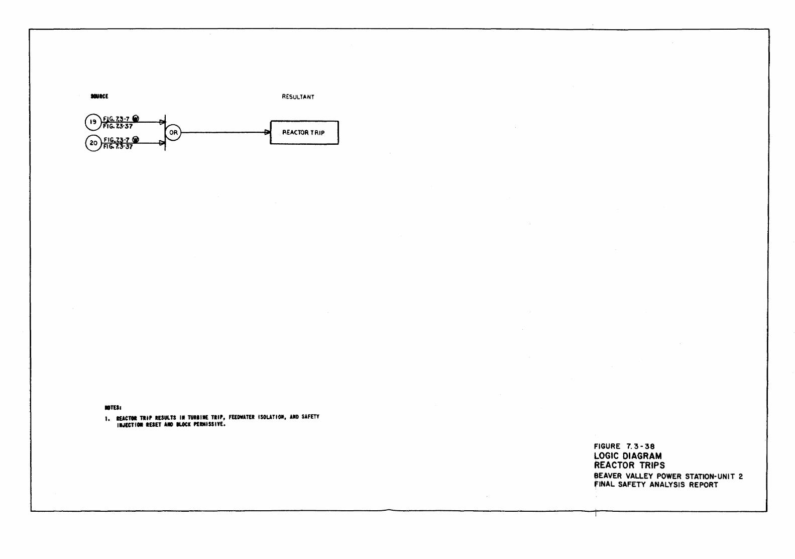
Diet RESULTANT
l'3 FiG. 7._!-7 Q .... I f"IG.l3-37 ... Q .... REACTOR. TRIP
20 FIG.23-7 6ib v . -FIG. 7.3-37
•m= 1. IEACTOI TIIP IESULTS II TUIIIIE TIIP, FEEDWAT£1 ISOUTIOif, AU SAFm
llt.IECTI11 IESET AIO ILOCI PEIMISSIYE.
FIGURE 7. 3-38 LOGIC DIAGRAM REACTOR TRIPS BEAVER VALLEY POWER STATION-UNIT 2 FINAL SAFETY ANALYSIS REPORT
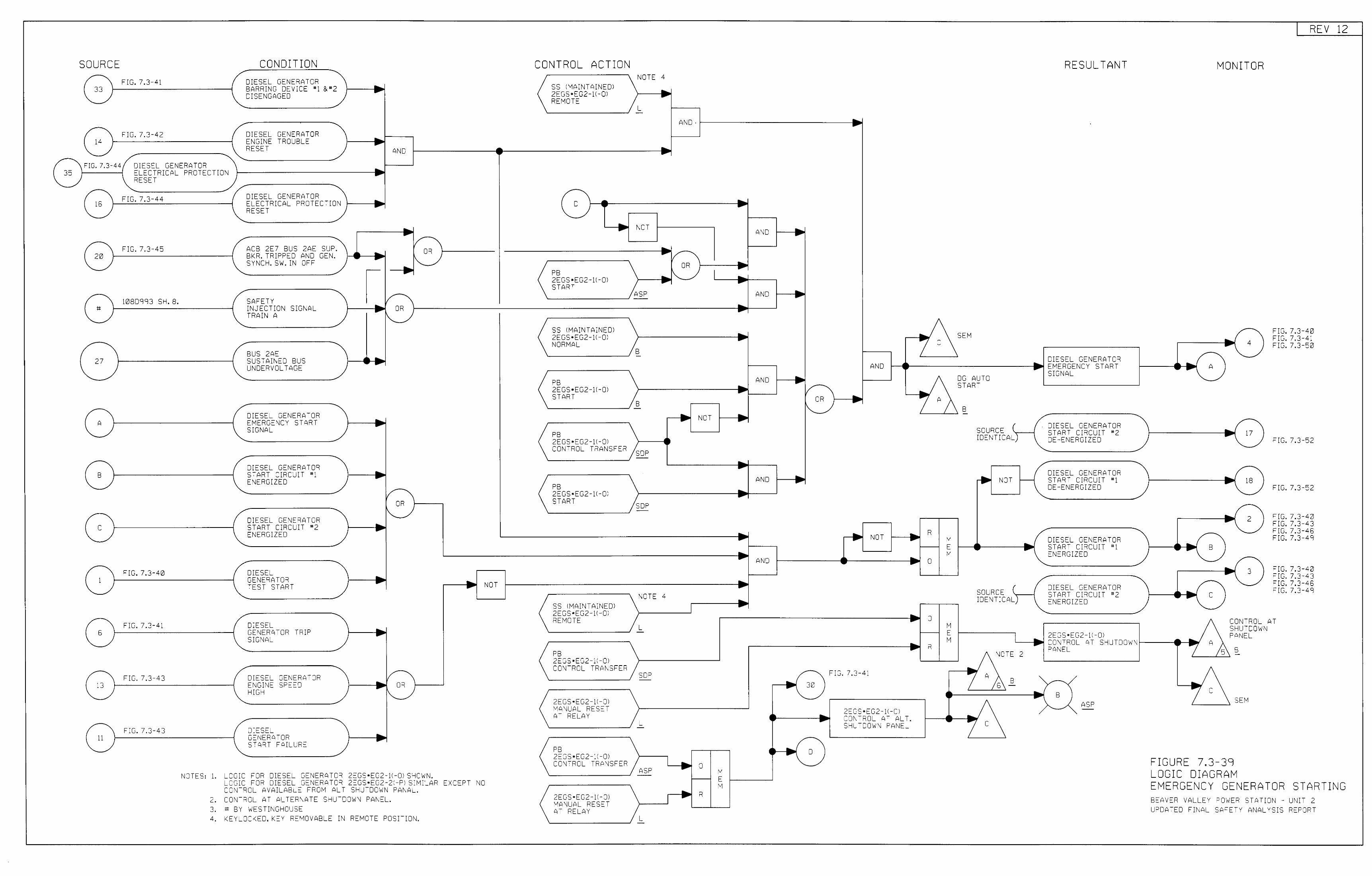
SOURCE
33
14
-FIG. 7.3-44
35
-( 16
20
;;
27
-A
B
-
1
13
CONDITION
FIG. 7.3-41 DIESEL GENERATOR BARRING DEV1CE #) &"2 • DISENGAGED
FIG. 7.3-42 DIESEL GENERATOR • ENGINE TROUBLE RESET
..... AND
DIESEL GENERATOR __.., ELECTRICAL PROTECTION -RESET
FIG. 7.3-44
FIG. 7.3-45
10sogg3 SH. 8.
FIG. 7.3-40
FIG. 7.3-41
FIG. 7.3-43
FIG. 7.3-43
DIESEL GENERATOR ELECTRICAL PRD'ECTION RESET
ACB 2E7 BUS 2AE SUP. BKR. TRIPPED AND GEN. SYNCH. SW. IN OFF
SAFETY INJECTION SIGNAL TRAIN A
BUS 2AE SUSTAINED BUS UNDERVOLTAGE
DIESEL GENERATOR EMERGENCY START SIGNAL
DIESEL GENERATOR START CIRCUIT #' . ENERGIZED
DIESEL GENERATOR START CIRCUIT "2 ENERGIZED
DIESEL GENERATOR TEST START
DIESEL GENERATOR TRIP SIGNAL
DIESEL GENERA-OR ENGINE SPEED HIGH
DIESEL GENERATOR START FAIL'~RE
_.. .....
.. ....
... OR ... I"-,..--- .. ...
1/-• DR ....
I\..
__.., .....
__.., ....
.. -/-
OR \._
NOTES: 1. LOGIC FOR DIESEL GENERATOR 2EGS•EG2-11-0I SHO'WN. LOGIC FOR D!ESEL GENERATOR 2EGS•EG2-21-P: SIMILAR CONTROL AVAILABLE FROM ALT SHU-DOWN PANAL.
2. CONTROL AT ALTERNATE SHUTDOWN PANEL. 3. ;; Bv WESTI~,GHOUSE
4. KEYLOCKED, KEY RE"10VABLE IN RE~C-E POSITION.
NOT
EXCEPT NO
CONTROL ACTION
SS !MAINTAINED! 2EGS•EG2-H-Ol REMOTE
-D .. - ... -
PB 2EGS•EG2-l<-Ol STA"<T
SS ltv"AINTAINEOl 2EGS•EG2-11-0l NORMAL
PB 2EGS•EG2-ii-Ol START
PB 2EGS•EG2-11-0l CONTROL TRANSFER
PB 2EGS•EG2-11-0I START
SS IMAINTAINE'JI 2EGS•EG2-li-OI REMCTE
PB 2EGS•EG2-1:-0I CONTROL -RANSFER
2EGS•EG2-11-01 1-'t;NUAL RESET AT RELAY
PB 2EGS•EG2-11-0l cow-ROL TRANSFER
2EGS•EG2-JI-OI MANUAL RESE-A- RELAY
NCTE 4
.... -L -
AND·
.. ..
__.... -\OT • AND .. .. .. v
OR __.... -.. I'-._ I .. ... -
ASP AND __.., ..... - ... ...
... ... B -
AND ... .. - v OR
B I"-- __.., __.., - NCT -
SOP - ... - • AND -_ .... ...
SOP -
AND
NOTE 4
L
SOP 30
L
D
0 ASP M E M
R
L
__.., -
AND
•
NOT
FIG. 7.3-41
2EGS•EG2-J:-OI CONTROL t;T ALT. SHUTDOWN PANEL
... 7 .. 7
R
0
0
R
c
A
M E M
M E M
SEM
iJG AUTO START
B -SOURCE ( IDENTICAL)
~ NOT
SOURCE IDENTICAL
• ..
RESULTANT
DIESEL GENERATOR EMERGENCY START SIGNAL
O:ESEL GENERATOR START CIRCUIT "2 DE -ENERGIZED
DIESEL GENERATOR START CIRCUIT "1 DE-ENERGIZED
DIESEL GENERATOR START CI"<CUIT #'
ENERGIZED
O:ESEL GENERATOR START CI"<CUIT "2 ENERGIZED
2EGS•EG2-11-0l
__.... A -
B
c
MONITOR
~ 4
-
.. 17 ...
• 18 ....-
2
REV 12
FIG. 7.3-40 FIG. 7.3-41 FIG. 7.3-50
FIG. 7.3-52
FIG. 7.3-52
FIG. 7.3-40 FIG. 7.3-43 FIG. 7.3-46 FIG. 7.3-49
FIG. 7.3-40 FIG. 7.3-43 FIG. 7.3-46 FIG. 7.3-49
CCNTROL AT S~UTDOWN PANEL
'---II~ CONTROL AT SHUTDCWNI---------~
NOTE 2 PANEL
B
ASP
c
c '-------'
SEM
FIGURE 7,3-39 LOGIC DIAGRAM EMERGENCY GENERATOR STARTING BEAVER VALLEY ~OWER STATION - UNIT 2 L~CATED FINAL SAFETY ANALYSIS REPORT
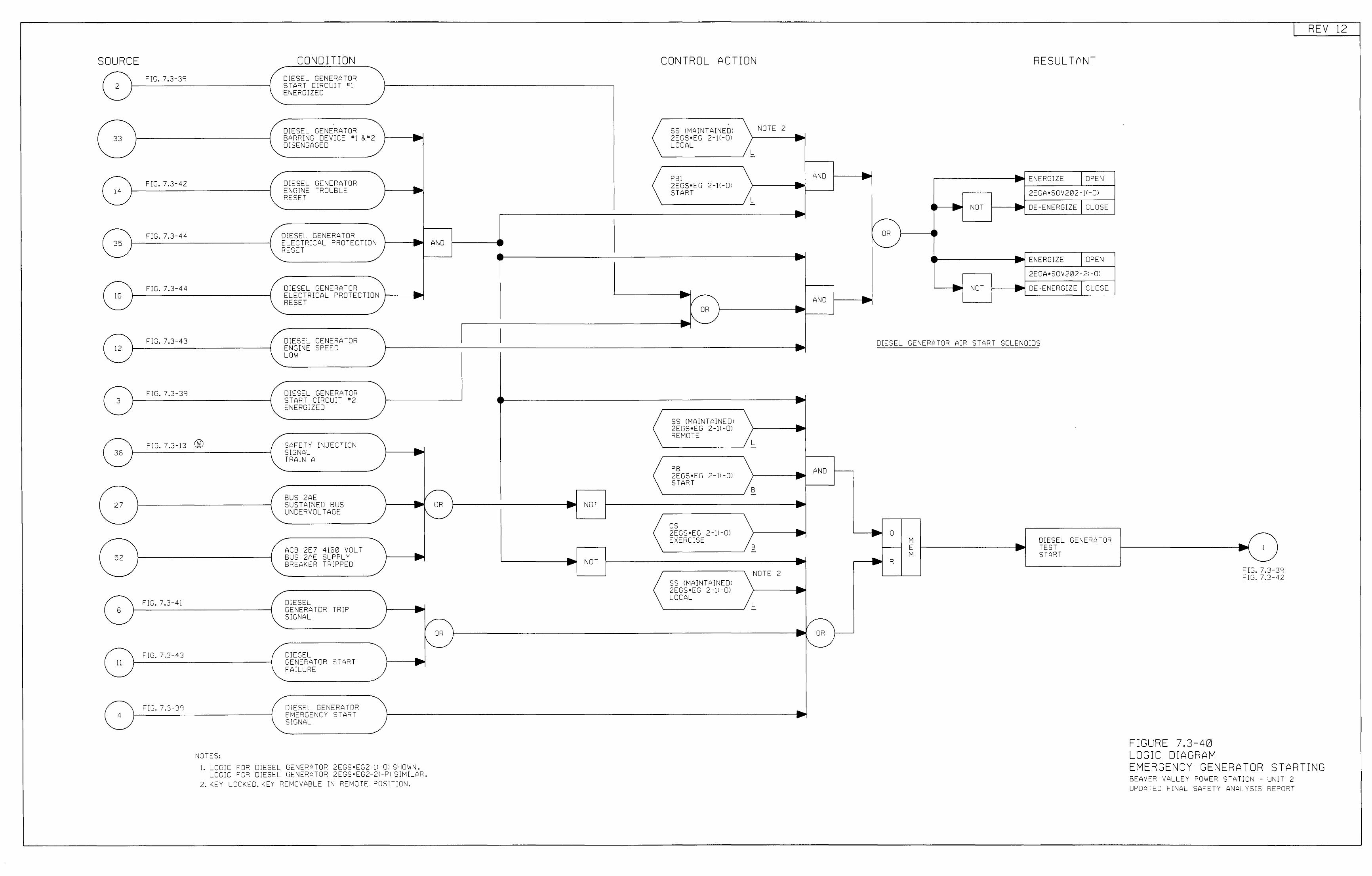
SOURCE FIG. 7.3-39
2
(,:\ FIG. 7.3-42 vi--------i 0 FIG. 7.3-44 vi--------i
FIG. 7.3-44
FIG. 7.3-43 12
FIG. 7.3-39 3
G FIG. 7.3-13 ®
27
52
-( 6
FIG. 7.3-41
-FIG. 7.3-43
11
FIG. 7.3-39 4
-
NOTES:
CONDITION DIESEL GENERATOR START CIRCUIT "1 ENERGIZm
DIESEL GENERATOR BARRING DEVICE "1 & "2 DISENGAGED
DIESEL GENERATOR ENGINC: TROUBLE RESET
DIESEL GENERATOR ELECTRICAL PROTECTION RESET
DIC:SEL GENERATOR ELECTRICAL PROTECTION RESET
DIESEL GENERATOR ENGINE SPEED LOW
DIESEL GENERATOR START CIRCUIT "2 ENERGIZED
SAFETY INJECTION SIGNAL TRAIN A
BUS 2AE SUSTAINED BUS UNDERVOLTAGE
ACB 2E7 4160 VOLT BUS 2AE SUPPLY BREAKER TRIPPED
DIESEL GENERATOR TRIP SIGNAL
DIESEL GENERATOR START FAILURE
DIESeL GENERATOR EMERGENCY START S!GNAL
.. ---.... -.... -... ...
1. LOGIC FOR DIESEL GENERATOR 2EGS•EG2-11-0l SHOW~.
AND
/ OR
"-
v OR
I'-..
LOGIC FOR DIESC:::L GENERATOR 2EGS•EG2-21-PI SIMILAR. 2. KEY LCCKED, KEY REMOVABLE IN REMOTE POSITION.
.... NOT -
• NOT
CONTROL ACTION
SS l'v!A:NTAINEO) 2EGS•EG 2-1:-0l LOCAL
PB1 2EGS•EG 2-1\-Q) START
SS IMAI~ TAINEDI 2EGS•EG 2-11-01 REMOTE
PB 2EGS•EG 2-11-0l START
cs 2EGS•EG 2-11-0l EXERCISE
SS IMAINTAINEDI 2EGS•EG 2-11-0l LOCAL
NOTE 2
L
L -
B -
B -
NOTE 2
L -
A\iD
AND
.. -
.... -- AND -.. -• ... .. .... -
/ .. OR .. \.
.. -
RESULTANT
.----------1~ ENERGIZE OPEN
~JT
NOT
2E GA •SOV 202 -!( -Ol
1----.-.! DE-ENERGIZE CLOSE
ENERGIZE OPEN
2EGA•SOV202-21 -01
1---~ DE-ENERGIZE CLOSE
DIESEL GENERATOR AIR START SOLENOIDS
.. iJ M DIESEL GENERATOR E .... TEST -'vi START .... R -
FIGURE 7,3-40 LOGIC DIAGRAM
.... 1 -FIG. 7.3-FIG. 7.3-
39 42
REV 12
EMERGENCY GENERATOR STARTING BEAVER VALLEY POWER STATICN - UNIT 2 UPDATED FINAL SAFETY ANALYS:S RE~ORT
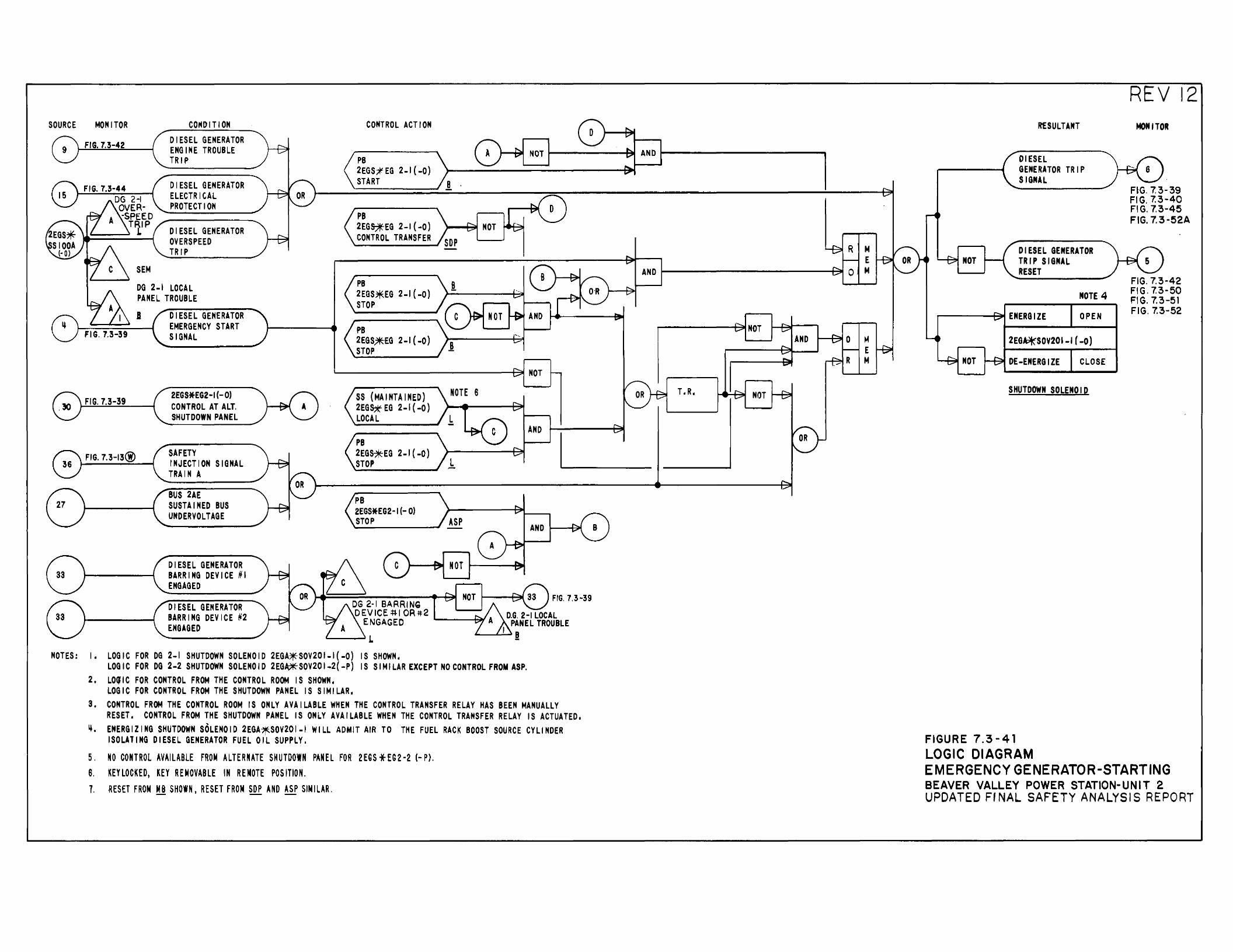
SOURCE MONITOR
FIG. 7.3-42
FIG. 7.3-39
FIG. 7.3-13@)
CO"DITION DIESEL GENERATOR ENGINE TROUBLE TRIP
DIESEL GENERATOR ELECTRICAL PROTECTION
DIESEL GENERATOR OVERS PEED TRIP
SEM
DG 2-1 LOCAL PANEL TROUBLE
DIESEL GENERATOR EMERGENCY START SIGNAL
2EG S*EG2 -I (- 0) CONTROL AT ALT. SHUTDOWN PANEL
SAFETY INJECTION SIGNAL TRAIN A
BUS 2AE SUSTAINED BUS UNDERVOLTAGE
DIESEL GENERATOR BARRING DEVICE #I ENGAGED
DIESEL GENERATOR BARRING DEVICE #2 ENGAGED
CONTROL ACTION
PB 2EGS;;f-EG 2-1 (-0) START
PB 2EGS:*EG 2-1 ( -0) CONTROL TRANSFER
PB 2EGS~EG 2-1 (-0} STOP
PB 2EGS?IHG 2-1 (-0) STOP
SS (MAINTAINED) 2EG~ EG 2-1 ( -0) LOCAL
PB 2EG~EG 2-1 ( -0) STOP
PB 2EGS*EG2-I {- 0) STOP
NOT
NOT
NOTE 6
L
L
ASP
NOT
NOT
AND
AND
FIG. 7.3-39 D.G. 2-1 LOCAL
PANEL TROUBLE I I
NOTES: I. LOGIC FOR DG 2-1 SHUTDOWN SOLENOID 2EGA~SOV201-I(-O) IS SHOWN; LOGIC FOR DG 2-2 SHUTDOWN SOLENOID 2EG"*'SOV201-2(-P) IS SIMILAREXCEPTNOCONTROLFROMASP.
2. LOqiC FOR CONTROL FROM THE CONTROL ROOM IS SHOWN. LOGIC FOR CONTROL FROM THE SHUTDOWN PANEL IS SIMILAR,
3. CONTROL FROM THE CONTROL ROOM IS ONLY AVAILABLE WHEN THE CONTROL TRANSFER RELAY HAS BEEN MANUALLY RESET. CONTROL FROM THE SHUTDOWN PANEL IS ONLY AVAILABLE WHEN THE CONTROL TRANSFER RELAY IS ACTUATED,
ij, ENERGIZING SHUTDOWN SOLENOID 2EGA~SOV201-I WILL ADMIT AIR TO THE FUEL RACK BOOST SOURCE CYLINDER ISOLATING DIESEL GENERATOR FUEL OIL SUPPLY.
5. NO CONTROL AVAILABLE FROM ALTERNATE SHUTDOWN PANEL FOR 2EGS * EG2 ·2 (- P). 6. KEYLOCKED, KEY REMOVABLE IN REMOTE POSITION. 1. RESET FROM M B SHOWN, RESET FROM SOP AND ASP SIN I LAR.
AND
M E
AND M
NOT M E M
T. R. NOT
RESULTANT
DIESEL GENERATOR TRIP SIGNAL
DIESEL GENERATOR NOT TRIP SIGNAL
RESET
NOTE 4
ENERGIZE OPEN
2EG~SOY201-1(-0)
NOT DE-ENERGIZE CLOSE
SHUTDOWN SOLENOI~
FIGURE 7.3-41 LOGIC DIAGRAM
REV 12 MONITOR
FIG. 7.3-39 FIG. 7.3-40 FIG. 7.3-45 FIG. 7.3-52A
FIG. 7.3-42 FIG. 7.3-50 FIG. 7.3-51 FIG. 7.3-52
EMERGENCY GENERATOR-STARTING BEAVER VALLEY POWER STATION- UNIT 2 UPDATED Ff NAL SAFETY ANALYSIS REPORT
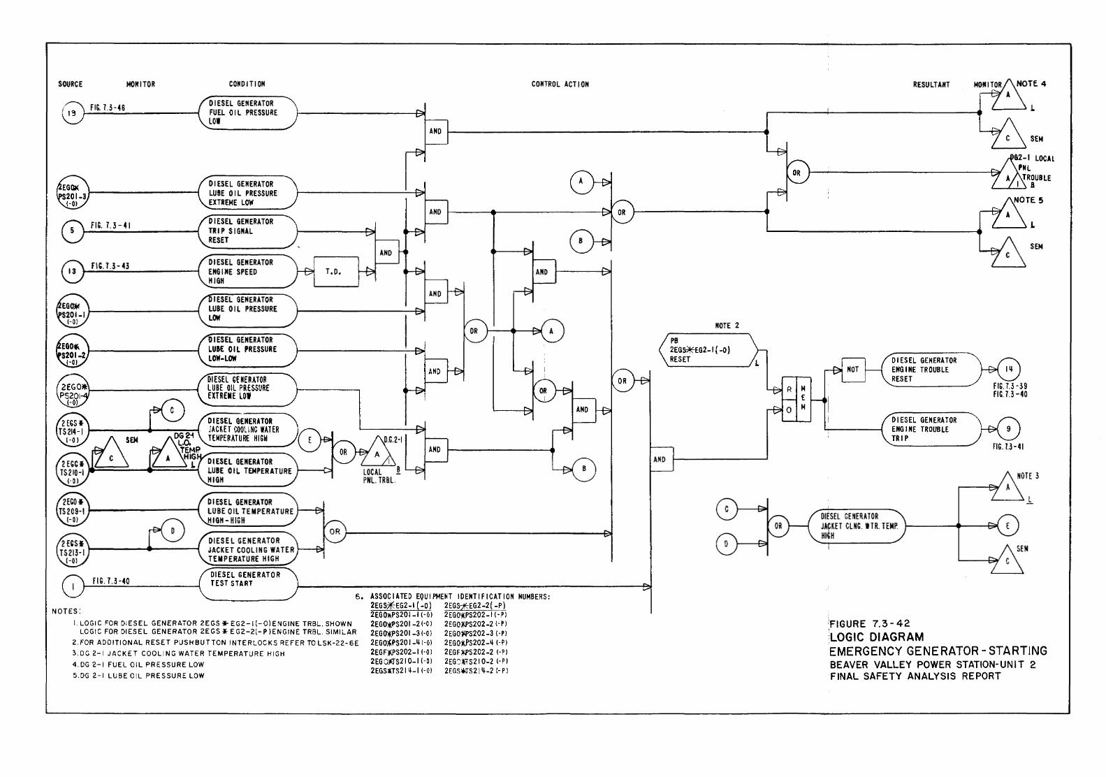
SOURCE MONITOR
FIG. 7.3-46
FIG. 1.3-41
FIG.U-43
FIC.U-40
CONDITION
Dl ESEL GENERATOR FUEL OIL PRESSURE LOI
DIESEL GENERATOR LUBE OIL PRESSURE EXTREME LOW
DIESEL GENERATOR TRIP SIGNAL RESET
DIESEL GENERATOR ENGINE SPEED HIGH
IESEL GENERATOR LUBE OIL PRESSURE LOW
DIESEL GENERATOR LUBE OIL PRESSURE LOW-LOW
DIESEL GENERATOR LUBE OIL PRESSURE EXTREME LOW
Dl ESEL GENERATOR JACKET COOL! NG WATER TEMPERATURE HIGH
DIESEL GENERATOR LUBE OIL TEMPERATURE 1----C:>I HIGH
DIESEL GENERATOR LUBE OIL TEMPERATURE HIGH-HIGH
DIESEL GENERATOR JACKET COOLING WATER TEMPERATURE HIGH
DIESEL GENERATOR TEST START
CONTROL ACTION
6, ASSOCIATED EQUIPMENT IDENTIFICATION NUMBERS:
NOTES:
I. LOGIC FOR Dl ES EL GENERATOR 2EGS *" E G 2-1 (- 0) ENGINE TRBL. SHOWN LOGIC FOR DIESEL GENERATOR 2EGS ¥ E G2-2(- P )ENGINE TRBL. SIMILAR
2. FOR ADO ITI ON AL RESET PUSHBUTTON I NTE RLOC KS REFER TO LSK-22- 6 E 3.0G 2-1 JACKET COOLING WATER TEMPERATURE HIGH
4. DG 2-1 FUEL 01 L PRESSURE LOW
5.DG 2-1 LUBE OIL PRESSURE LOW
2EG S*EG2 -I ( -0) 2 EGS;*:EG2 -2 ( -P) 2EG OlPS20 I -1 I-0 I 2 EGO*PS202 -I HI 2EG())Kf'S201 -21-0 I 2EGO*-PS202-2 1-P I 2EG~PS20 I -3 I -0 I 2 EG011PS202 -3 I-PI 2EGO~PS201-LII-OI 2EGOtPS202-LI I-PI 2EGF)(?S202-1 1·01 2EGF*PS202-2 1-Pl 2EG O*l'S21 0-1 1-01 2EG:tTS21 0-2 1-P l 2EGSlTS21 11-1 I- 0 l 2EGSliJ'S 21 Ll-2 1- PI
NOTE 2
PB 2EG~EG2-1 ( -0) RESET
M E M
RESULTANT
DIESEL GENERATOR ENGINE TROUBLE RESET
DIESEL GENERATOR ENGINE TROUBLE TRIP
DIESEL GENERA TOR JACKET CLNG. ITR. TEMP. HIGH
·FIGURE 7.3-42 LOGIC DIAGRAM
FIG. 7.3-39 FIG.7.3 -40
FIG. 1.3-41
EMERGENCY GENERATOR- STARTING BEAVER VALLEY POWER STATION-UNIT 2 FINAL SAFETY ANALYSIS REPORT
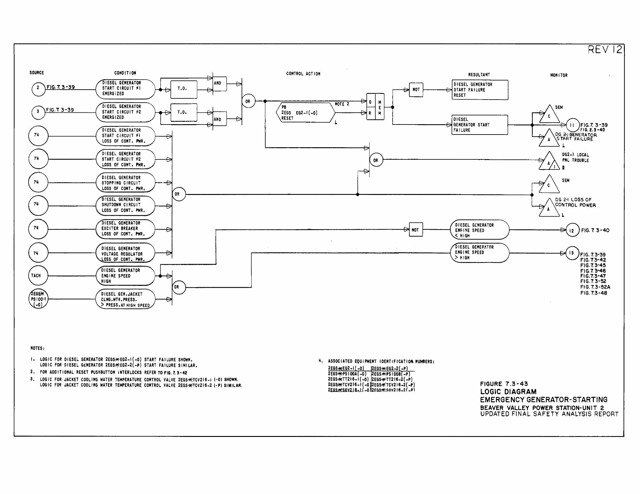
SOURCE
FIG. 7. 3-39
FIG. 7. 3-39
COHDITION
DIESEL GENERATOR START CIRCUIT #I ENERGIZED
DIESEL GENERATOR START CIRCUIT #2 ENERGIZED
DIESEL GENERATOR START CIRCUIT #I LOSS OF CONT. PWR.
DIESEL GENERATOR START CIRCUIT #2 LOSS OF CONT. PWR.
DIESEL GENERATOR STOPPING CIRCUIT LOSS OF CONT, PWR.
DIESEL GENERATOR SHUTDOWN CIRCUIT LOSS OF CONT. PWR.
T. D.
T.D.
CONTROL ACTION
PB 2EGS EG2-1(-0) RESET
NOTE 2 M E M
RESULTANT DIESEL GENERATOR
1-----+-=oo~ START FA I LURE RESET
DIESEL "'-------+311 GENERATOR START FA I LURE
REV 12
MONITOR
FIG. 7. 3-39 FIG. 2.3-40
DG 2-1 GliNERATOR START FAILURE
'---~ .L
DG2-I LOCAL PNL TROUBLE
'--...J....~I
SEM
DG 2·1 LOSS OF CONTROL POWER
'---~.L
DIESEL GENERATOR EXCITER BREAKER LOSS OF CONT. PWR.
~----------------------------------------------------~NOT DIESEL G(NERATOR ENC,INE SPEED <HIGH
FIG. 7. '3 -40
NOTES:
DIESEL GENERATOR VOLTAGE REGULATOR LOSS OF CONT. PWR.
DIESEL GENERATOR ENGINE SPEED HIGH
DIESEL GEN,JACKET CLNG. WTR. PRESS. ) PRESS. AT HIGH SPEED
I, LOGIC FOR DIESEL GENERATOR 2EGS~EG2-1(-0) START FAILURE SHOWN, LOGIC FOR DIESEL GtNERATOR 2EGS~EG2-2(-P) START FAILURE SIMILAR,
2. FOR ADDITIONAL RESET PUSHBUTTON INTERLOCKS REFER TO FIG. l 3-42 3. LOGIC FOR JACKET COOLING WATER TEMPERATURE CONTROL VALVE 2EGS~TCV216-I (·0) SHOWN.
LOGIC FOR JACKET COOLING WATER TEMPERATURE CONTROL VALVE 2EGS*TCV216-2 (-P) SIMILAR.
ij, ASSOCIATED EQUIPMENT IDENTIFICATIOk NUMBERS: 2EGS EG2-1 -0 2EGS~EG2-2 -P 2EGS~PSIOOA -0 2EGS~PSIOOB -P 2EGS~TT216-I(-O) 2EG~TT216-2(-P) 2EGS~TCV216-1(-0 2EGS~TCV216-2(-P) 2EGS#SOY218-1 ( -0 2E&s*~CinV218-2 ( _p\
DIESEL GENERATOR ENGINE SPEED >HIGH r------~FIG. 7.3-39
FIG. 7.3-42 FIG.7. 3-45
FIGURE 7.3-43 LOGIC DIAGRAM
FIG. 7. 3-46 FIG.7.'3-47 FIG. 7. 3-52 FIG. 7.3-52A FIG. 7.3-48
EMERGENCY GENERATOR-STARTING BEAVER VALLEY POWER STATION-UNIT 2 UPDATED FINAL SAFETY ANALYSIS REPORT
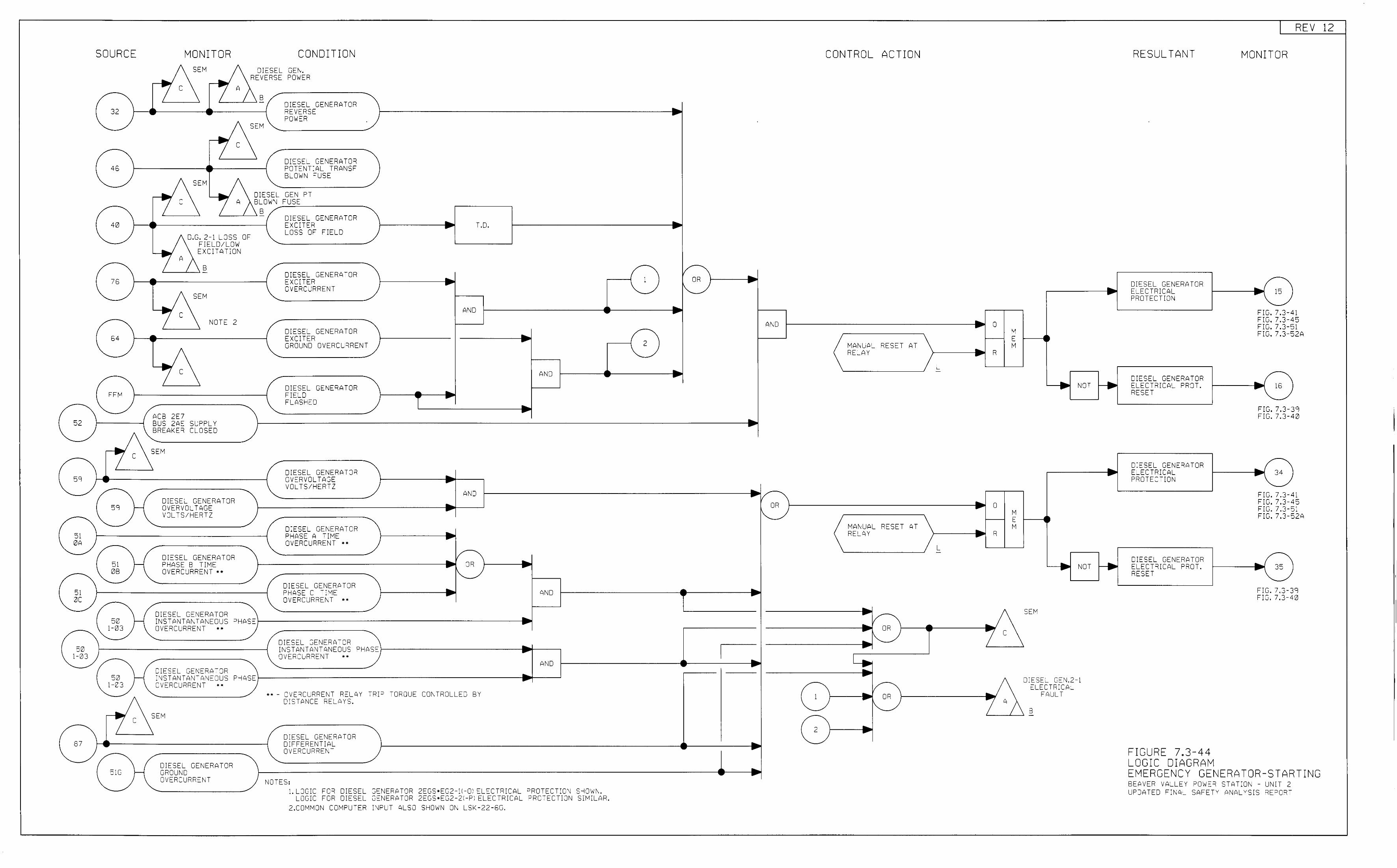
SOURCE
32
40
64
52
c
59 H
59 l-i
51 0A
51 l-i 0B
51 0:::
50 l-i 1-03
50 1-03
50 H 1-03
... 7 c
87 -51G H
MONITOR CONDITION SEM DIESEL GEN.
REVERSE POWER c
B - DIESEL GENERATOR REVERSE POWER
SEM
c DIESEL GENERATOR POTENT:AL TRANSF BLOWN "USE
SEM D:ESEL GEN PT c BLOWN FUSE
B -
D.G. 2-1 LOSS 0" FIELD/LOW EXCITATION
B -
SEM
NOTE 2
ACB 2E7 BUS 2AE SL;PPLY BREAKER CLOSED
SEM
DIESEL GENERATOR OVERVOLTAGE VOLTS/HERTZ
DIESEL GENERATOR PHASE B TIME OVERCURRENT ••
D:ESEL GENERATOR INSTANTANTANEOUS PHASE OVERCURRENT ••
DIESEL GENERATOR INSTANTANTANEOUS P-1ASE OVERCJRRENT ••
SEM
CIESEL GENERATOR GRCJUND CVERCURRENT
DIESEL GENERATOR EXCITER T.D. LOSS OF FIELD
DIESEL GENERATOR EXCITER OVERCJRRENT
AND
DIESE_ GENERATOR EXCITER GROUND OVERCURRENT
AND
DIESEL GENERATOR FIELD FLASHED
DIESEL GENERATOR OVERVOLTAGE VOLTS/HERTZ
AND
DIESEL GENERA-OR PHASE A TIME • OVERCURRENT ••
/ • OR • "'-DIESEL GENERATCR ... PHASE C T:ME AND -OVERCURRENT ••
• DIESEL GENERATOR INSTANTANTANECUS PHASE ... -CJVERCURRENT ••
AND ... -•• - OVE'lCURRENT RELAY T'l!P TOROUE CONTROLLED BY
DISTANCE RELAYS.
DIESE_ GENERATOR DIFFERENTIAL OVERCURRENT
NOTES: 1. LOGIC FOR DIESEL GENERATOR 2EGS•EG2<1-0; ELECTRICAL P=iOTECTICN S-10WN.
LOGIC FOR DIESEL GO:NERATJR 2EGS•EG2-21-Pi ELECTRICAL PROTECTICN SIMILAR. 2.COMMON COMPWER :NPUT ALSO S-10WN ON LSK-22-6G.
CONTROL ACTION
1 OR
AND 0 M E
MAI'-IUA_ RESET AT M RELAY R
L -
• 1/-OR • 0
I~ M E
MANUAL RESET AT M ... RELAY - R
L -
• •v- ... .._ OR - 7 c 1'\.... ... -... I .. - =--1/
1 .. OR I'-..._ A
= 2 • ... -..
NOT
• •
... NOT ~ -SEM
DIESEL GEN.2-1 EI_ECTRICAL
FAULT
B -
RESULTANT
DIESEL GENERATOR ELECTRICAL PROTECTION
D:ESEL GENERATOR ELECTRICAL PROT. RESET
DIESEL GENERATOR ELECTRICAL PROTECTION
DIESEL GENERATOR ELECTRICAL PROT. RESET
FIGURE 7.3-44 LOGIC DIAGRAM
REV 12
MONITOR
15
FIG. 7.3-41 FIG. 7.3-45 FIG. 7.3-51 FIG. 7 .3-52A
16
FIG. 7.3-39 FIG. 7.3-40
.. 34 -FIG. 7.3-Flu. 7.3-FIG. 7.3-FIG. 7.3-
... 35 -
41 45 51 52 A
FIG. 7.3-3 9 0 FIG. 7.3-4
EMERGENCY GENERATOR-STA RTING BEAVER VALLEY POWER STATION - UNIT 2 LPDATED F:NAL SAF TY ANA Y - R E L S.S EPORT
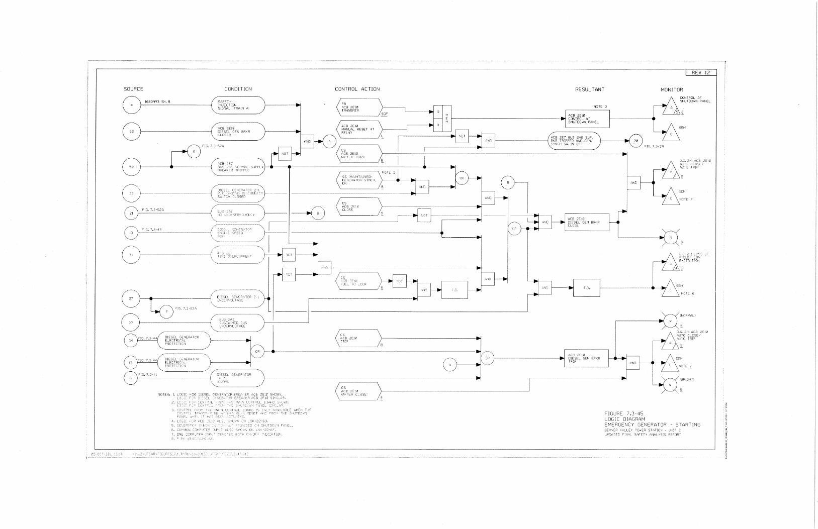
SOURCE CONDITION
52
2.
CONTROL ACTION
P9 'C3 ?E10 T~ANSFER ~ ~------_) SCP
~ \ ~R:;> I -----------------~
~-----_;8
(~' \ ~ ,__ __ ___...., \,, _ _/
RESULTANT
REV 12
MONITOR CONTROL AT SHUTDOWN ?YNEL
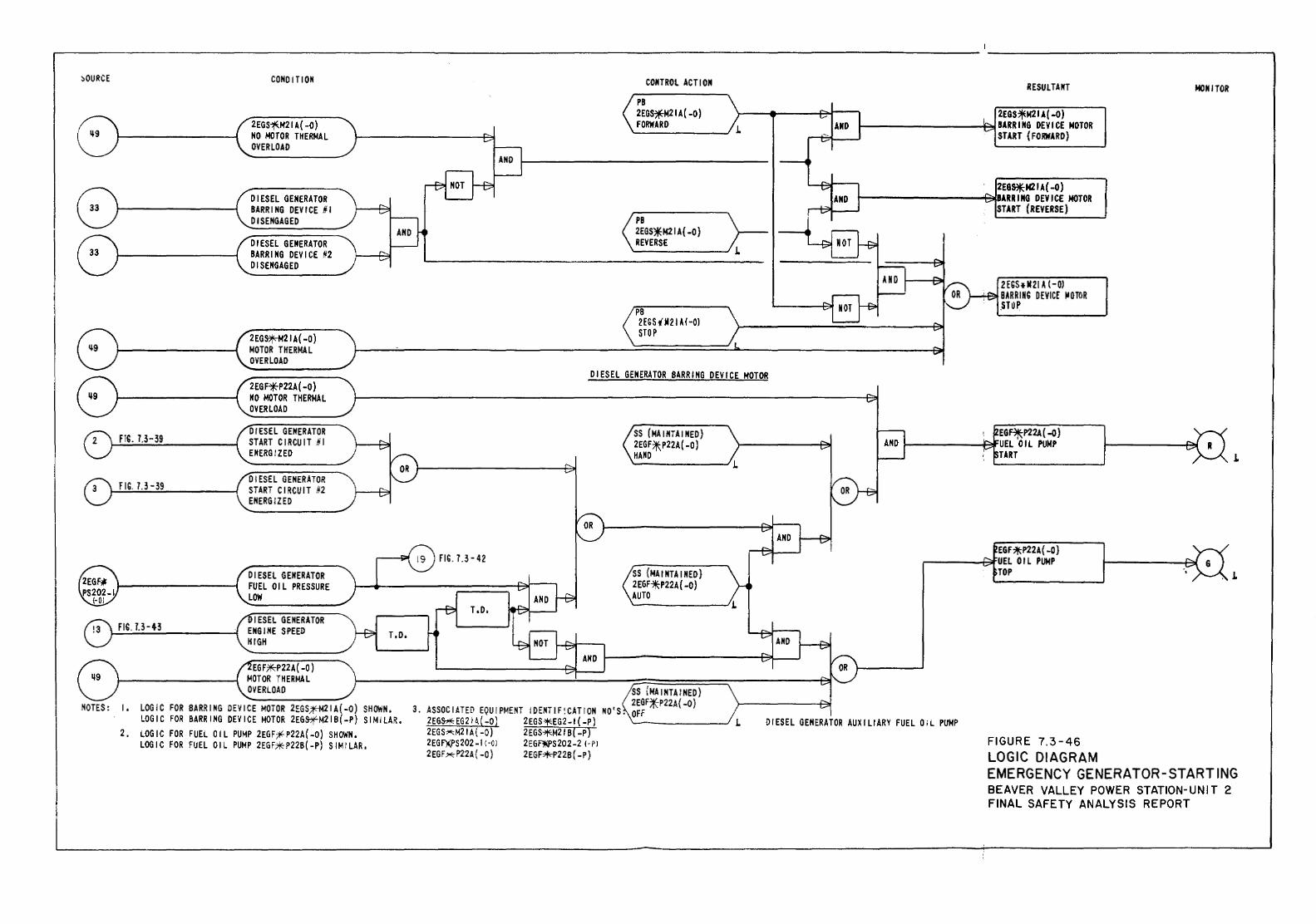
~OURCE
FIG. 7.3-39
FIG. U-39
fiG. 7.3-43
CONDITION
2EGS~M21 A { -0) NO MOTOR THERMAL OVERLOAD
DIESEL GENERATOR BARRING DEVICE HI DISENGAGED
DIESEL GENERATOR BARRING DEVICE #2 DISENGAGED
2EGs+-M21 A( -0) MOTOR THERMAL OVERLOAD
2EGFiE"P22A(-O) NO MOTOR THERMAL OVERLOAD
DIESEL GENERATOR START CIRCUIT Iii EM ERG I ZED
DIESEL GENERATOR START CIRCUIT #2 ENERGIZED
DIESEL GEitERATOR FUEL OIL PRESSURE LOW
J ESEL GENERATOR ENGINE SPEED KIGII
EG F%::P22A ( -0) MOTOR Til ERMA L O~ERLOAD
NOTES: I, LOGIC FOR BARRING DEY ICE MOTOR 2EGS;¥:-M21 A ( -0) SHOWN, LOGIC FOR BARRING DEVICE MOTOR 2EGS1fM21B(-P) SIMILAR,
2, LOGIC FOR FUEL OIL PUMP 2EGF~P22A{-O) SIIOWN, LOGIC FOR FUEL OIL PUMP 2EGF~P22B(-P) SIMILAR,
CONTROL ACTION RESULTANT MONITOR PB 2EGS*M21A( -0) 2EGS7jEM21 A{ -0) FORWARD BARRING DEVICE MOTOR .L START (FORWARD)
2EQ~N21A(-O) BARRING DEVICE MOTOR START (REVERSE)
PB 2EGS*N21 A( -0) REVERSE
2EGSIII21 A (-OJ BARRING DEVICf IIGffiR
PB .STOP 2EGS tM21 AI -OJ STOP
DIESEL GENERATOR BARRING DEVICE MOTOR
fiG. 7.3-42
T.D.
SS (MAINTAINED) 2EGF:¥,P22A( -0) llANO
SS {MAINTAINED) 2EGF*P22A(-O) AUTO
SS {MAINTAINED) 2EGF*P22A{-O) 3, ASSOCIATED EQUIPMENT IDENTIF!CATION NO'S. OFF
2EG&*EG2H.(-O) 2EGS-1E:EG2-1{-P) '-------..../ .L 2EGS~M21A(-O) 2EGS~M21B(-P) 2EG F)(PS 202 -I ( -0 I 2 EGFM'S 202-2 I-PI 2EGF~P22A{-O) 2EGF~22B(-P)
EG~P22A( -0) UEL OIL PUMP TART
EGF;lltP22A(-O} ,-----.j.::;jf'UEL 0 ll PUMP
TOP
DIESEL GENERATOR AUXILIARY FUEL O;L PUMP
FIGURE 7.3-46 LOGIC DIAGRAM
.L
EMERGENCY GENERATOR-STARTING BEAVER VALLEY POWER STATION-UNIT 2 FINAL SAFETY ANALYSIS REPORT
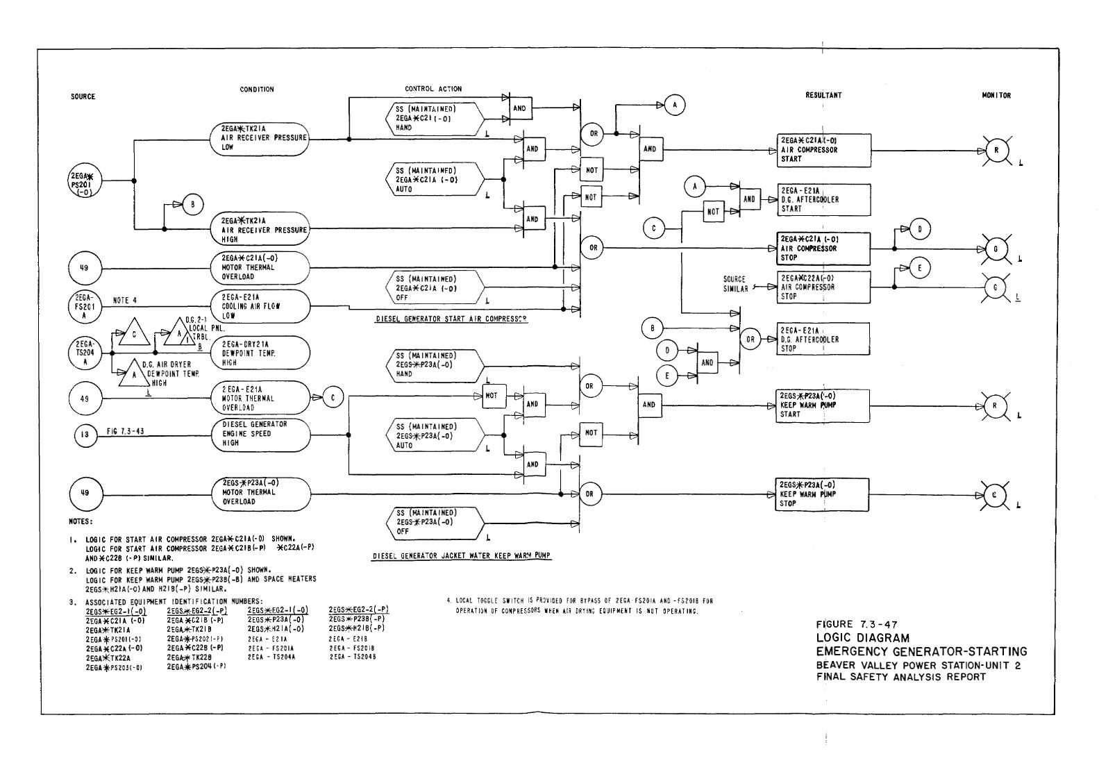
CONDITION SOURCE
2EGA*TK21A
CONTROL ACTION
SS (MAIMTillNED) 2EGA*C21 t- OJ HAND
SS (MA I NTA HfED) 2EGA*C21A t-0) AUTO
L
RESULTANT
2EGA * C21 A,'( -OJ 1---------~~ A I R Ca.4PRESSOR
START
2 EGA- E21A ! D.C. AFTERCOOLER START
MONITOR
L
AIR RECEIVER PRESSURE 1------------------ei~_.J
NOTE 4
O.G. AIR DRYER OEWPOINT WIP.
L...-_ _.HIGH l
FIG U-43
HIGH
2EGA*C21A( -0) MOTOR THERMAL OVERLOAD
2 EGA- E21A MOTOR THERMAL OVERLOAD
DIESEL GENERATOR ENGINE SPEED 1\IGH
0--·-~---NOTES:
I , LOG I C FOR START A I R COMPRESSOR 2EGA* C21 A (-OJ SHOWN, LOGn FOR START A I R COMPRESSOR 2EGA * C21 B (,. Pl *C22A (-PI AND *C22B t • PJ SINILAR.
2. L:OG I C FOR KEEP WARM PUMP 2EG~P2 3A { -0) SHOWN, LOGIC FOR KEEP WARM PUMP 2EG~P23B{-B) AND SPACE HEATERS 2EGS~H21A{-O)AND H21B(-P) SIMILAR.
3. ASSOCIATED EQUIPMENT IDENTIFICATION NUMBERS: 2EGS~EG2-t(-Ol 2EGSttEG2-21:~ 2EGS~EG2-1 -0 2EGA*C21 A (-OJ 2EGA *C21 B (-PI 2EGS*:P23A -0 2EGA~TK21A 2EG~TK21B 2EGS~H21A(-O) 2EGA * PS201! -0 l 2EGA-+!'S202 H l 2 EGA - f2 U 2EGA*C22.\ (-0) 2EGA*C22B (-P) 2m- FS201A 2EGA}jETK22A 2EGA;;:f TK22B 2 EGA - TS204A 2EGA*?S 2031 • 01 2EGA*PS20~ I· Pl
SS (MAINTAINED) 2EGA*C21A (~O) OFF .L
DIESEL GENERATOR START AIR COMPRESS~~
SS (MAINTAINED) 2EG5-3f:P23A( -0) HAND
SS (MAINTAINED) 2 EG~P23A { -0) AUTO
SS (MAINTAINED) 2EG~P23A(-O) OFF
L
DIESEL GENERATOR JACKET WATER KEEP WARM PUMP
2EGA*C21A t·OI 1----------------1~ AIR COMPRESSOR
STOP
2 EGA*!: 22 A ti-Ol AIR CO~P RES~OR STOP
2EGA-E21A' D.G. AFT ERCOPL ER STOP
2EGS;;fn3A('-0) 1-----------f~ KEEP WARM p,tJMP
START
2EGS*P23A( -0) 1--------------~~ KEEP WARM I'!JMP
STOP
L
l
L
L
2EGS*EG2-2 -P 2EGS*P23B -P) 2EGS*H21B(-P) 2EG~·E2tB
4. lOCAL TOGGlE SWITCH IS H'JV I OED FOR BYPASS Of 2EGA · fS20 lA AND - f S 201a fOR 0 ~ERATION Of con RESSORS II HEN AIR DRYING EO UIP IH NT IS NOT 0 PtRAT IN G.
2 EGA- FS20 18 2 EGA - TS204S
FI~GURE 7. 3-4 7 LOGIC DIAGRAM EMERGENCY GENERATOR-STARTING BEAVER VALLEY POWER STATION-UNIT 2 FINAL SAFETY ANALYSIS REPORT
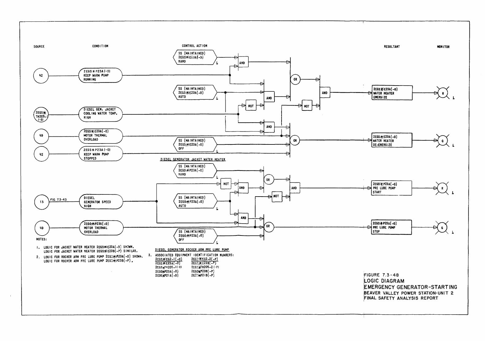
SOURCE
FIG. 7.3-43
CONDITION
2EGS*E23A(-O) MOT OR TH ERMA L OVERLOAD
2EGS*P23A (-0) KEEP WARM PUMP STOPPED
DIESEL GENERATOR SPEED HIGH
2EGO:*:P23A( -0) MOTOR THERMAL OVERLOAD
NOTES• ATER HEATER 2EG""~!(:P) SIMilAR. ( O' SH~WN,
LOGIC FOR JAC~ :ATER HEATER 2EGS>fE ~P23A(-O) SHOWH. I • LOGIC FOR JACK R ARN pRE LUBE PUMP ~;:Oli<P23B( ·P) •
LOGIC FOR ROCK~R ARM PRE LUBE PUMP 2. LOGIC FOR ROCK 3.
CONTROL ACT ION
SS (MA 1 NTAINED) 2EGS*E23A(-Ot) HAND
SS (MAINTAINED) 2EGS:*E23A(-O) OFF
SS (MAINTAINED) 2EG~P23A ( -0) AUTO
RESULTANT
2EGO*P2JA{-O) PRE LUBE PUMP L_----------------------~~s~n_R_T ____ _
2EG0*'23A{ -0) PRE LUBE PUMP ------------------------------'1us~ro~P ________ __
· E 7 3-48 iFIGUR ·
NOitiTOR
J.
1.
J.
1.
iLOGIC DIAGRAM RATOR-STARTING ·!EMERGENCY GEN;ER STATION-UNIT 2 REAVER VALLEY :~LYSIS REPORT ,fiNAL SAFETY A !
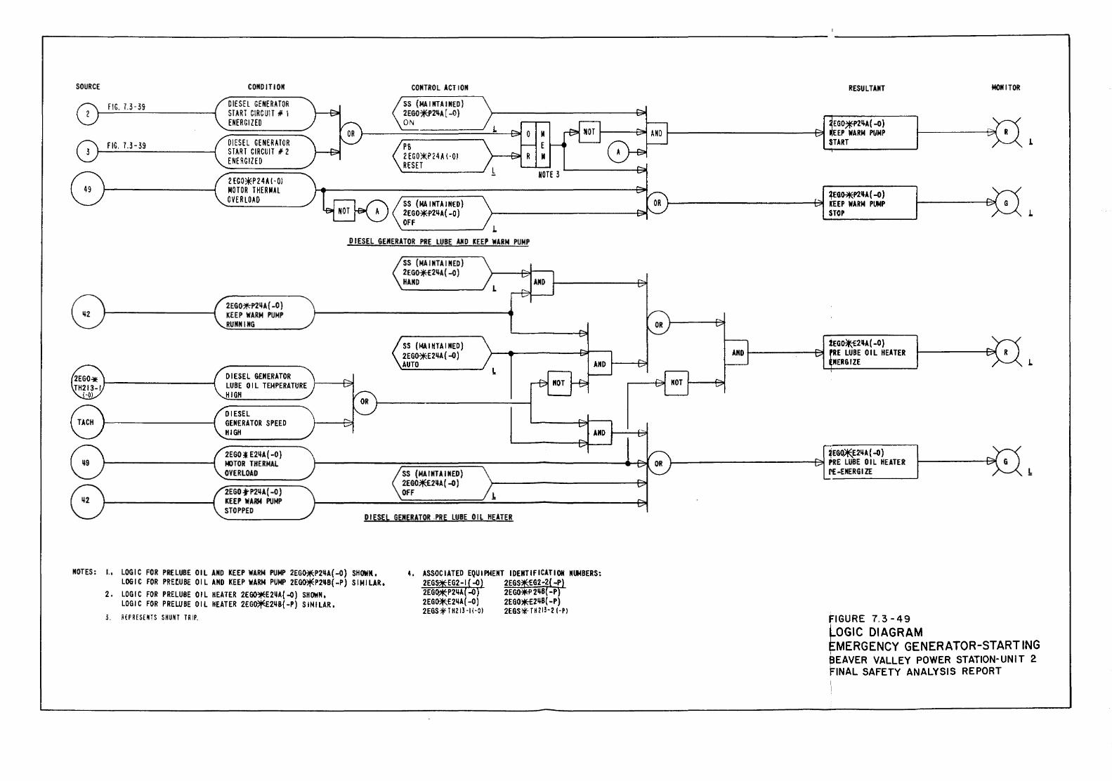
SOURCE CONDITION CONTROL ACT ION
fiG. 7.3-39 DIESEL GENERATOR START G!RG Utl fl. 1 ENERGIZED
fIG. 7.3-39 DIESEL GENERHOR START CIRCUIT If 2 ENERGIZED
2EGO*P 24A {-OJ MOTOR THERMAL OVER LO.t.D SS (MAINTAINED)
2EG0~2~A(-O) OFF
L DIESEL GENERATOR PRE LUBE AHD KEEP WARN PUMP
SS (MAINTAINED) 2EGffl2~A(-O) HAND
2EGOJ!!;-P2~A{-O) KEEP WARN PUMP RUNNING
SS (J.IAIHTAINED) 2EG011E::E2~A { -0) AUTO
DIESEL GENERATOR !. LUBE OIL TEMPERATURE HIGH
DIESEL GENERATOR SPEED HIGH
2EGO :f E2~A { -0) t«lTOR THERMAL OVERLOAD SS (MAINTAINED)
2EG07!E£2~A(-O) 2EGO .j-P2~A( -0) OFF !. KEEP WARM PUNP STOPPED
DIESEL GENERATOR .PR~ LUBE OIL HEATER
NOTES: I., LOGIC FOR PRELUB£ OIL AND KEEP WARM PUMP 2EG~P2~A{-O) SHOWN., LOGIC FOR PREfUBE OIL AND KEEP WARM PUMP 2E~P2~B(-P) SIMILAR.
2. LOGIC FOR PRELUBE OIL HEATER 2EGO~E2~A{-D) SHOWN. LOGIC FOR PREUJBE OIL HEATER 2EG~2~B{-P) SIMILAR,
3. RfPRfSf~TS SHUNT TRI~
II E II
RESULTANT
~EGO.*P2~A(-O) .EEP WARN PUMP START
tEG~~A(-0) IEEP WARN PUMP STOP
lEG~2~A(-O) tRE LUBE OIL HEATER
HERGIZE
~EG~2~A(-O) PRE LUBE OIL HEATER I'E -ENERGIZE
FIGURE 7. 3-49 LOGIC DIAGRAM
MONITOR
L
L
L
1.
EMERGENCY GENERATOR-STARTING aEAVER VALLEY POWER STATION-UNIT 2 FINAL SAFETY ANALYSIS REPORT
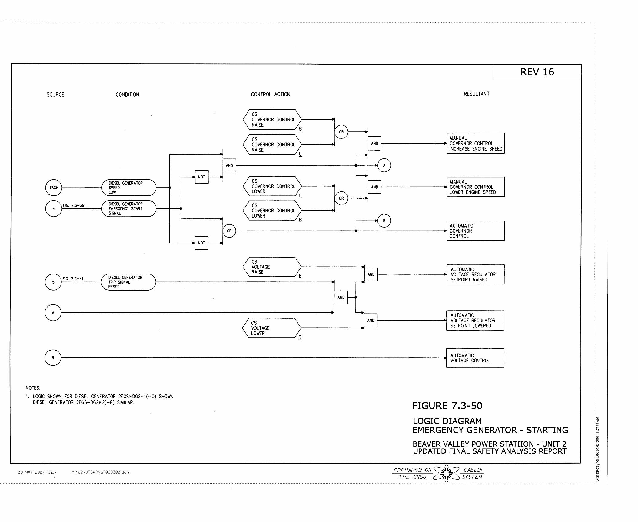
SOURCE
FIG. 7.3-.39
FIG. 7.3-41
CONDITION
DIESEL GENERATOR SPEED LOW
DIESEL GENERATOR EldERGENCY START SIGNAL
DIESEL GENERA TOR TRIP SIGNAL RESET
r----.t NOT ~--.t
'-----.t NOT ~..-t
CONTROL ACTION
cs GOVERNOR CONTROL RAISE
"'-------J .e. cs GOVERNOR CONTROL RAISE
"'------- 1.
RESULTANT
MANUAL AND t----------.t GOVERNOR CONTROL
INCREASE ENGINE SPEED
AND ~----------------------~-~
cs GOVERNOR CONTROL LOWER
cs GOVERNOR CONTROL LOWER
MANUAL AND ~--------~ GOVERNOR CONTROL
LOWER ENGINE SPEED
AUTOMATIC 1------------------+------------------..t GOVERNOR
cs VOLTAGE RAISE
cs VOLTAGE LOWER --------.e.
AND
AND 1---------~
CONTROL
AUTOMATIC VOLTAGE REGULATOR SETPOINT RAISED
AU TOM A TIC AND 1-------------.. VOLTAGE REGULATOR
SETPOINT LOWERED
REV 16
f:\ J AUTOMATIC ~f---------------------------------------------------.!l VOLTAGE CONTROL
NOTES:
1. LOGIC SHO'M-1 FOR DIESEL GENERATOR 2EGS*DG2-1(-0) SHOWN. DIESEL GENERA TOR 2EGS-DG2*2( -P) SIMILAR.
03-MAY-2007 11:27 M:\u2\ UFSAR\g 7030500.dgn
FIGURE 7.3-50 LOGIC DIAGRAM EMERGENCY GENERATOR- STARTING BEAVER VALLEY POWER STATIION - UNIT 2 UPDATED FINAL SAFETY ANALYSIS REPORT
(\
PREPARED ON<:::::~"~/ CAE DO! THE CNSU L.-~1\~~ SYSTEM
--------------------------------------------------------------------------------------------------------------------------------------------------------------------------------------------------------------------------------------------------------------------------------------- _':(_--------------------------------------------------- -----------------------------------
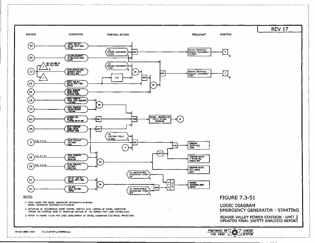
ACIJ'l£/ 4161'111.! BUS 2AE Slfl'tY BR11R Tllii'PED
ACIJ 2Eli DltSELGEN.m Tllii'PED
I. LOGIC SHOWN FOR DIESEL GENERATOR 2EGS*OG2-IC-Ol SHOWN. DIESEL GENERATOR 2EGS*DG2-2<-Pl SIMILAR
2. INITIATION OF ISOCHRONOUS DROOP CONTROL PERMITS SLOW LOADING OF DIESEL GENERATOR DURING THE EXERCISE MODE OF OPERATION INSTEAD OF THE NORMAL FAST LOAD CAPABILITIES.
3. REFER TO FIGURE 7.3-44 FOR LOGIC DEVELOPMENT OF DIESEL GENERATOR ELECTRICAL PROTECTION.
FIGURE 7.3-51 LOGIC DIAGRAM EMERGENCY GENERATOR - STARTING BEAVER VALLEY POWER STATIION - UNIT 2 UPDATED FINAL SAFETY ANALYSIS REPORT
PREPARED ON 'A? CAEDDI 0 28-AUG-2008 13:54 K:\u2\UFSAR\g7939510.dgn THE CNSU C.."-~~ SYSTEM , ~---------------------------------------------------------------------------------------------------------------------------------------------------Y------------------------------------------------•
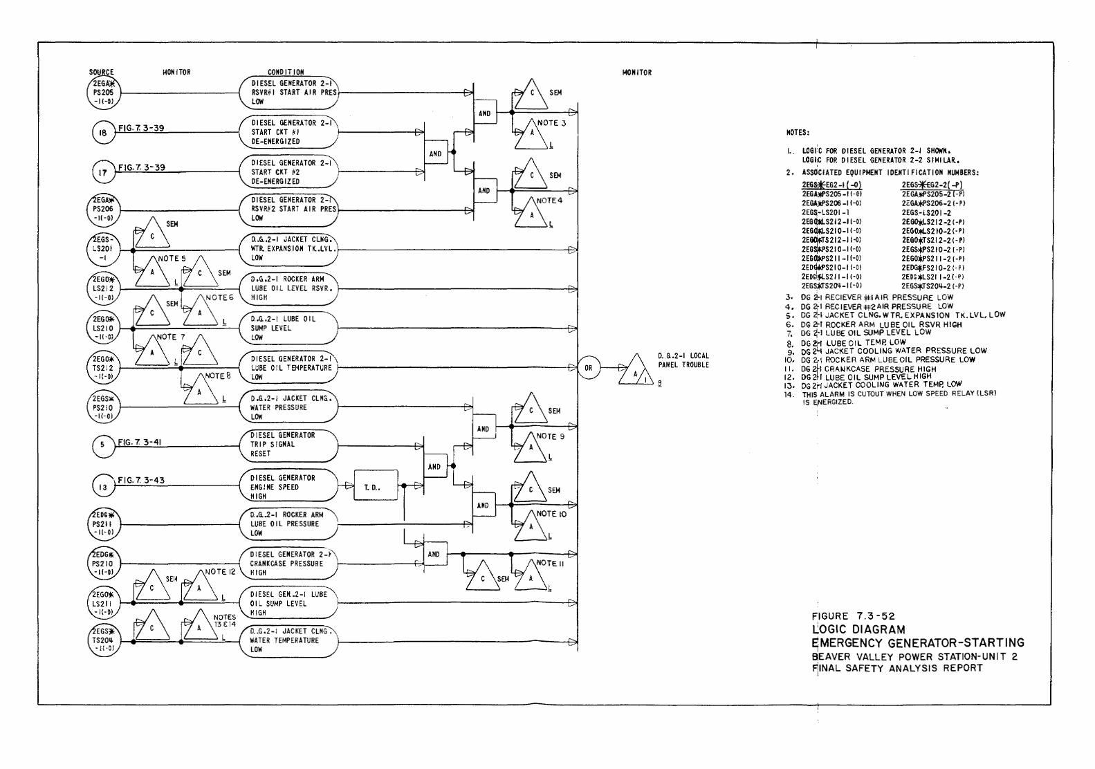
l-ION !TOR
FIG. 7. 3-39
FIG-7. 3-39
FIG. 7. 3-41
FIG. 7. 3-43
COHO IT ION DIESEL GENERATOR 2-1 RSVRiil START AIR PRES/-----------~ LOW
DIESEL GENERATOR 2-1 START CKT !i I DE-ENERGIZED
DIESEL GENERATOR 2-1 START CKT 112 DE-ENERGIZED
DIESEL GENERATOR 2-RSVRii2 START AIR PRESJ------------+71 LOW
n.Q.2-I JACKET CLNG, WTR..EXPANS ION TK..LVL. f---------------------~ LOW
O.G.2-1 ROCKER ARM LUBE 01 L LEVEL RSVR. 1---------------------8ol H IGH
n,Q,2-I LUBE OIL SUMP LEVEL LOW
DIESEL GENERATOR 2-1 LUBE OIL TEMPERATURE LOW
O.G..2-I JACKET CLHG., WATER PRESSURE LOW
DIESEL GENERATOR TRIP SIGNAL RESET
DIESEL GENERATOR ENGINE SPEED HIGH
O .• Q.2-I ROCKER ARM LUBE OIL PRESSURE LOW
DIESEL GENERATOR 2-~" CRANKCASE PRESSURE HIGH
DIESEL GEK.2-I LUBE
T. D ..
OIL SUMP LEVEL 1----------------------f~ HIGH
O .. G.2-I JACKET CLHG. WATER TEMPERATURE LOW
loiONITOR
D •. G..2-I LOCAL PANEL TROUBLE
NOTES:
1.. LOGI'C FOR DIESEL GENERATOR 2-1 SHOWN.. LOGtC FOR DIESEL GENERATOR 2-2 S I Ml LAR.,
2. ASSOCIATED EQUIPMENT IDENTIFICATION NUMBERS:
2EG~EG2-1(-0) 2EGS~G2-2(-P) 2EGAJWS205 -I I-OJ 2EGA~S205-2 (-Pl 2EGA):PS206 -11-0l 2EGA;f.PS206-2 I- P J 2EG$-LS201-l 2EGS-tS201-2 2EG Q)1.S212 -I I -OJ 2EGOld-S21 2 -2 I -P l 2EG~S21 0-1 I -OJ 2EG~S 2 10-2 I· P l 2EGqfrrS212-I I ·OJ 2EGO*TS212-2 (- PJ 2EG*"S21 0-1 f-01 2EGS~S21 0-2 I -PJ 2EGIJW'S2 II -I I-OJ 2 EGO*"S2 II -21- P J 2EDWS21 0- I I -0 J 2 ED<>f_f'S21 0-2 I· P J 2EOGI.'fll.S211 -I I -OJ 2EDG *LS2 f I -2 ( • P J 2EGS~S2<N- f ( -0 J 2 EGS'I'JS20~-2 I -P J
3. DG 2-1 RECI EVER #I A I R PRESSURE lOW 4. DG 2,-1 RECIEVEA+tZAIR PRESSURE LOW S, OG 2~1 JACKET CLNG, WTR, EXPANSION TK. LVL, LOW 6. DG 2-1 ROCKER ARM LUBE OIL RSVR HIGH 7, DG ~-1 LUBE OIL SUMP LEVEL LOW 8. DG ~I LUBE OIL TEMP. LOW 9. OG 2'-1 JACKET COOLitJG WATER PRESSURE LOW
10. DG 2·1 ROCKER ARM LUBE. OIL PRESSURE LOW II. 06 ?~I CRANKCASE PRESSURE HIGH 12. DG 2J.r LUBE OIL SUMP LEVEL HIGH I 3. DG 2d JACKET COOLING WA TEA TEMP. LOW 14. THIS ALARM IS CUTOUT WHEN LOW SPEED RELAY {LSR)
IS E;NERGIZED.
FIGURE 7.3-52 J..:OGIC DIAGRAM ~ MERGENCY GENERATOR -STARTING BEAVER VALLEY POWER STATION-UNIT 2 Fi
11NAL SAFETY ANALYSIS REPORT
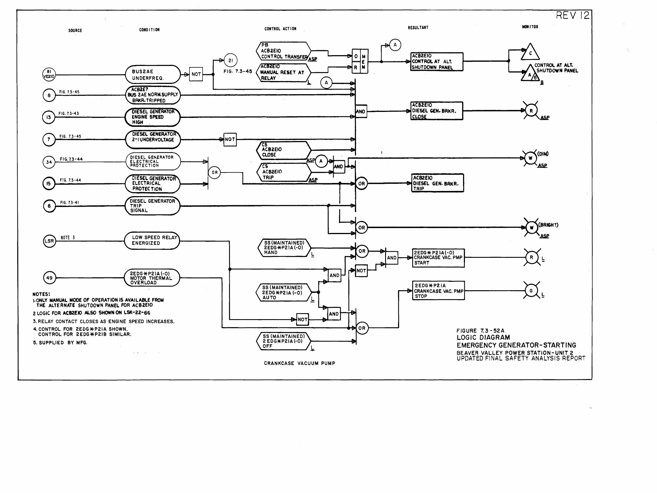
SOURCE CONDITION
BUS2AE NOT Fl G. 7.3-45 UNDERFREQ.
AC82E7 FIG. 7.3-45 BUS 2AE NORM.SUPPLY BRKR, TRIPPED
FIG. 7.3·43 DIESEL GENERATOR ENGINE SPEED HIGH
DIESEL GENERATO FIG. 7.3-45 2-1 UNDERVOLTAGE
F'IG. 7.:3-44 DIESEL GEN£RATOR EL.ECTRICAL PROT .ECT ION
FIG. 7.3-44 DIESEL GENERATOR· ELECTRICAL PROTECTION
FIG. 7.3-41 DIESEL GENERATOR TRIP SIGNAL
NOTE 3 LOW SPEED RELAY ENERGIZED 1---------.
NOTES~
2EDG*P21A (-0) MOTOR THERMAL OVERLOAD
!.ONLY MANUAL MODE OF OPERATION IS AVAILABLE FROM THE ALTERNATE SHUTDOWN PANEL FOR AC82EIO
2 LOGIC FOR ACB2EIO ALSO SHOWN ON LSK-22-66
3. RELAY CONTACT CLOSES AS ENGINE SPEED INCREASES. 4. CONTROL FOR 2EDG*P21A SHOWN.
CONTROL FOR 2EDG*P21B SIMILAR.
5. SUPPLIED BY MFG.
CONTROL ACTION
PB AC82EIO CONTROL TRANSF
cs ACB2EIO CLOSE
cs ACB2EIO TRIP
SS (MAINTAINED) 2EDG*P21A(-0) HAND
SS (MAINTAINED) 2EDG *P21A (-0) AUTO
SS (MAINTAINED) 2 EDG* P21A (-0) OFF
CRANKCASE VACUUM PUMP
N E M
REV 12 RESULTANT MOM I TOR
ACB2EIO CONTROL AT ALT. SHUTDOWN PANEL CONTROl AT ALT.
SHUTDOWN PANEL
.a
ACB2EIO DIESEL GEN. BRKR.
. CL
ACB2EIO DIESEL GEN. BRkR. TRIP
(BRI&HT)
2EDG* P21A(-O) AND ......,.-BIItCRANKCASE VAC. PMP 1------------{ L
START -
2EDG*P21A ....--&~CRANKCASE VAC. PM Pt--------......(
STOP --!:
FIGURE 7.3-52A LOGIC DIAGRAM EMERGENCY GENERATOR-STARTING BEAVER VALLEY POWER STATION-UNIT 2 UPDATED F!NAL SAFETY ANALYSIS REPORT
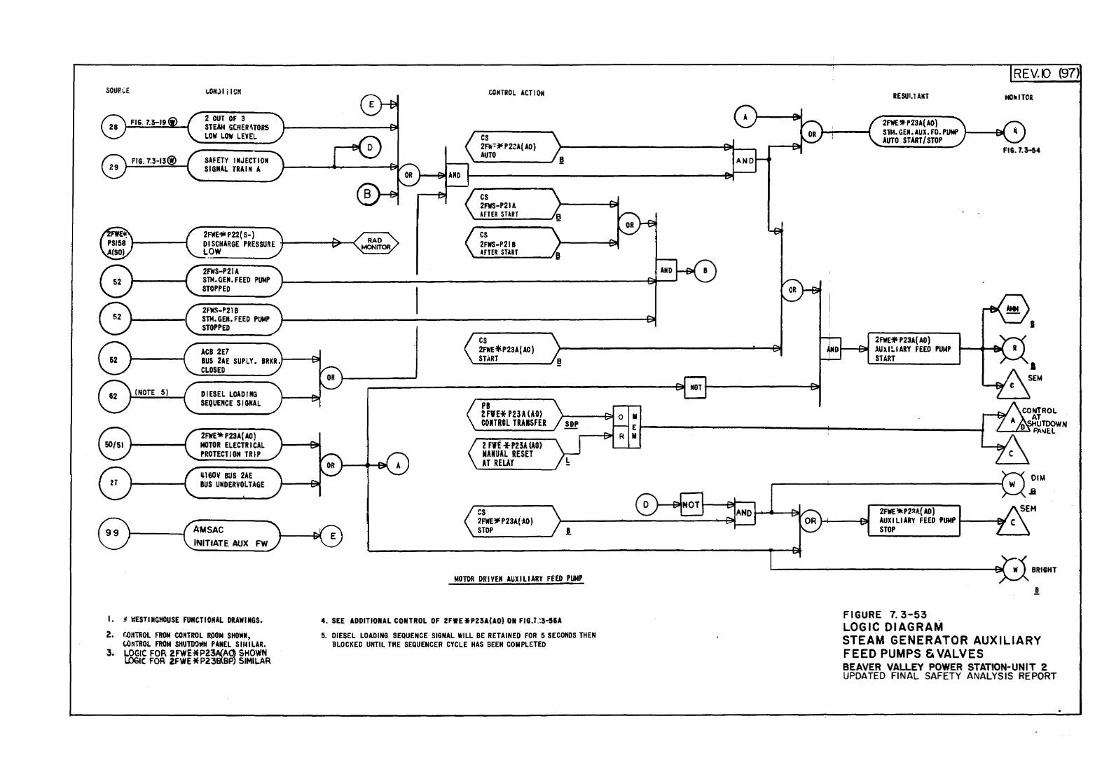
SOUR;;E
FIG. 7.3-13@)
i..ON.ili ICIC
2 OUT OF 3 STEAU GCHER\TORS LOW LOW LEVEL
SAFETY INJECTION SI,ONAL TRAIN A
2FWE* P 22( s-)
CONTROL ACTION
cs 2Ri=* P2ZA( AO) AUTO
cs 2FWS-P21A AFTER START
DISCHARGE PRESSURE +----~--< cs 2FWS-P21 B ~FTER START LOW ~----J
(NOTE 5)
2FWS-P21A STM.GEN.FEED PUMP STOPPED
2FWS-P21B STM.GEM.FEED PUMP STOPPED
ACB 2E7 BUS 2AE SUPLY. BRKR.I----91 CLOSED
DIESEL LOADING SEQUENCE SIGNAL
2FWE* P23A( AO) MOTOR ELECTRICAL PROTECTION TRIP
~160V BUS 2AE BUS UMDERVOLTAGE
AM SAC INITIATE AUX FW
I. # ~ESTIMCHOUSE FUNCTIONAL DRAWINGS.
2. f.CIITROL FROM toNTROL R0014 SHOWN, tO~TROL FROM SHUTDOWN PANEL SIMILAR.
3. L.OGIC FOR 2FWE * P23A(AQ SHOWN LOGIC FOR 2FWE*P238lBP) SIMILAR
cs 2FWE *P23A( AD)
'I..,;,ST.;.;.A;;.;.RT;..._ ___ ..J !!
PB 2FIHP23AUO) CONTROL TRANSFER
2 FIE +P23A lAO) MANUAL RESET AT RELAY
cs 2FWE,.P23A{-AO) STOP !.
MOTOR DRIVEN AUXILIARY FEED PUMP
4. SEE ADDITIONAL CONTROL OF 2FWE*P23A(AO) ON FIG.T.;3-56A
5. DIESEL LOADING SEQUENCE SIGNAL WILL BE RETAINED FOR 5 SECONDS THEN BLOCKED UNTIL THE SEQUENCER CYCLE HAS BEEN COMPLETED
REV.[) (97)
RESUI.l ANT NOJIITCR
2AIE 'Jf P23A( AO) STJ.1. GEN. AUX. FO. PIINP 1---~ AUTO START/ STOP
2FWE~ P23A( AO) 1--~ ..\U).I:..IARY FEED PUMP
START
2FWE'*P2::t~( AD)
FIG.U-54
I
AUXILIARY FEED PUMP 1----er STOP
FIGURE 7. 3-53 . LOGIC DIAGRAM
BRIGHT
STEAM GENERATOR AUXILIARY FEED PUMPS & VALVES BEAVER VALLEY POWER STATION-UNIT 2 UPDATED FINAL SAFETY ANALYSIS REPORT
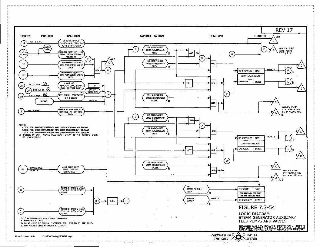
SOURCE MONITOR CONDITION
AUX. FD. PUMP STM SPL f---+------1 FROM 2RCS*SG21ACA-)
PRESSURE
2MSS*SOVIB5AIADI }---------; STM. ADMISSION VALVE
OPEN
2MSS*SOVIB501AOI }----------{ STM. ADMISSION VALVE
OPEN
LO-LO LEVEL
RAIN A STM. ADM. VLY. }-...r..&J...._.....::..._ _____ ; CONTROL AT CONTROL J-------1p--
ROOM
NOTES• 1. LOGIC FOR 2HSS*SIVIIJ5AlADI ANO 2MSS*SOVIIJ50CAOI SHOWN
LOGIC FOR 2HSS*SOVI05BCBPI ANO 2MSS*SOVIB5ECBPI SIMILAR LOGIC FOR 2HSS*SOVIB5CCCOI ANO 2MSS*SOVIII5FCCPI SIMILAR
2- OPENING OF BOTH VAL YES WILL ADMIT STEAM TO THE TURBINE ORIYE OF 2FWE*P22CS-l
AUXILIARY FEED PUMP TURBINE OVERSPEED
TURBINE DRIVEN AUX. }-----------{ FD. PUMP AUTO START
SIGNAL
TURBINE DRIVEN AUX. }-----------{ FD. PUMP AUTO START
SIGNAL
3. # WESTINGHOUSE FUNCTIONAL DRAWINGS 4. SUPPLIED BY MFG. 5. VALVE MUST BE MANUALLY ,QPENED ANO LATCHED AT THE PUMP. 6. FOR VALVES 2MSS*SOVI05A & D ONLY.
CONTROL ACTION
55 MAINTAINED 2MSS-SOVIB5AIAOI
OPEN
55 MAINTAINED 2MSS-SOVIB5ACAOI
CLOSE
55 MAINTAINED 2MSS-SOYIIJ50CAOI
AUTO
SS MAINTAINED 2MSS-SOVIIJ50CA01
OPEN
SS MAINTAINED 2MSS-SOVIB5DCADI
CLOSE
RESULANT
AUX. FW PUMP AUTO /AUTO START STOP
AUX. FW PUMP STM SUPPLY SOY SS IN CLOSE PDS e
AUX. FW PUMP STM SUPPLY SOV SS IN CLOSE POS
PB 2FWE*P22CS-l }--------~ENERGIZE
~T=RI:P::::::::~R MANUAL RESET }-N-"O-'-TE;;....;5;._----~ DE-ENERGIZE RESET
'-----__JL FIGURE 7.3-54 LOGIC DIAGRAM STEAM GENERATOR AUXILIARY FEED PUMPS AND VALVES BEAVER VALLEY POWER STAlliON - UNIT 2 UPDATED FINAL SAFETY ANALYSIS REPORT
: 2B-AUG-2BB8 !3.58 K;\u2\UFSAR\g71131154B.dgn PR_f~ARg:s: ~0~ ~"ffr: : L---------------------------------------------------------------------------------------------------------------------------------------------------v------------------------------------------------·
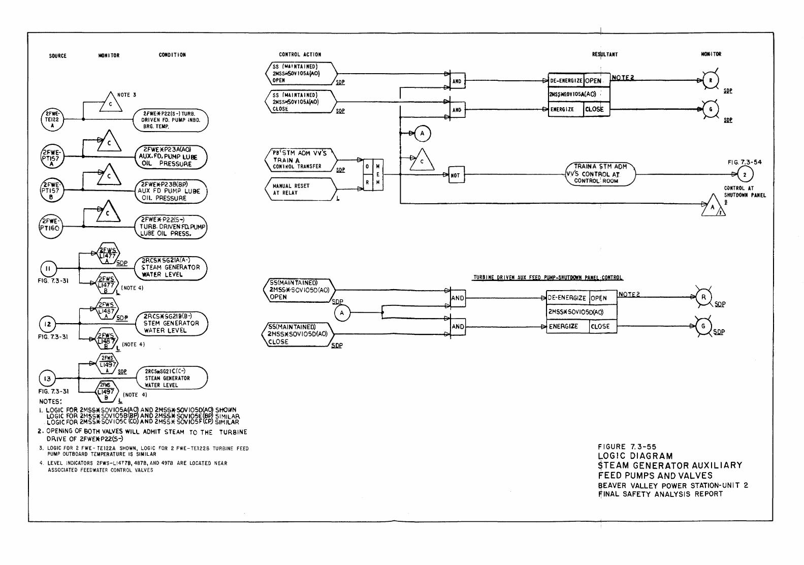
SOURCE MONITOR CONDITION
2FWE * P22 (S-I TURB. DRIVEN FD. PUMP INBD. BRG. TEMP.
2FWE*P23A(AO) 1--...._----~ AUX.FD.PUHP LUBE
OIL PRESSURE
2FWE*P2 3B(BP) )---....a.-----~AUX FO PUMP LUBE
FIG. 7.3-31
F'¥15 Ll-497
NOTES: 8 .h
OIL PRESSURE
2FWE * P2 2(5 -) T U RB. 0 RIVEN FD. PUMP LUBE OIL PRESS.
2RCS*SG21A A-STEAM GENERATOR WAH:R LEVEL
2RCS!tSG21C(C-) STEAM GENERATOR 'WATER LEVEL
4)
L LOGIC FOR 2MSS*SOVIOSA(A0~ AND 2M55)(-S0VIOSD~O~ SHOWN LOGIC FOR 2.MSS*SOVIOSB{BP AND 2MSS*SOVJ05E 8P. SIMILAR
. LOGIC FOR 2MSS*SOV 105C (CO AND 2MSS* SOVJOSF CP SIMILAR 2.. OPENING OF BOTH VALVES WILL AOHIT STEAM TO THE TURBINE
DRIVE OF 2FWEltP22(S-:) 3. LOGIC FOR 2 FWE- TE122A SHOWN, LOGIC FOR 2 FWE- TE12 28 TURBINE FEED
PUMP OUTS OARD TEMPER AT UR E IS Sl MILAR 4. LEVEL INDICATORS 2FWS-LI4778, 4878, AND 4978 ARE LOCATED NEAR
ASSOCIATED FEEDWATER CONTROL VALVES
CONTROL ACTION
SS (WAI NTA I NED) 2MSS~YJ05A~O) OPEN
SS (No\ I MTA I NED) 2MS S~OY I 05A~O) CLOSE
'PB 1STM ADM vv's TRAIN A CONlltOL TRANSFER
MON4TOR
TRAINA STM ADM FIG. 7.3-54
I •
~---------"':!. VVS CONTROL Al
MANUAL RESET AT RELAY
CONTROL1 ROOM CONTROL AT SHUTDOWN PANEL .1!
SS{MAIN TA I NED TURBINE DRIVEN AUX fEED PUHP-SHUTDQWN eAMEL·CONTROL
2MSS*SOVI05D(AO) \-----------~1-----, OPEN ~--------------~
2MSS* SOV IOSD(AO)
SS(MA IN TAl N EO) 1-------------~ ENERGIZE CLOSE: 2HSS)I(SOVIOSO(AO) 'r-------------QoL--1 CLOSE SDf
FIGURE 7. 3-55 LOGIC DIAGRAM STEAM GENERATOR AUXILIARY FEED PUMPS AND VALVES ~EAVER VALLEY POWER STATION-UNIT 2 FINAL SAFETY ANALYSIS REPORT
I
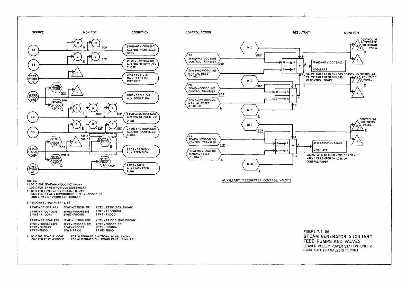
SOURCE MONITOR
NOTES: I. LOGIC FOR 2FWE * HCV IOOC ( AO) SHOWN
LOGIC FOR 2 FWE * HCVIOOE (AO) SIMILAR 2. LOGIC FOR 2 FWE * HC V 100 A (AO) SHOWN
LOGIC FOR 2 FWE * HCV 1008 (BP),2FWE* HCVIOOD( BP) AND 2 FWE !tHCVIOOF( BP) SIMILAR.
3. ASSOCIATED EQUIPMENT LIST
CONDITION
2F WE• HCVIOOA ( AO) AUX FOWTR.CNTRL, V.V. CLOSE
2RCS!tSG21 C( C-) MAIN FEED LINE PRESSURE
2RCS X SG21 c (C-) AUX FEED FLOW
2 FWE * HCV IOOA (AO) AUX. FDWTR. CNTRL. V. V. OPEN
2 F WE * HCVIOOA (AO) AUX.FDWTR. CNTRL. V.V. CLOSE
2 RCS * SG21 C(C-1 AUX FEED FLOW
2RCS•SG21A AUXILIARY FEED FLOW
2 FWE !tFT IOOA (AR) 2FWE!tFT 100 B (BR) 2FWE x FTlOO(CR) (SHOWN)
2 FWE * FIIOO A (AO) 2FWEx FIIOOB ( 80) 2FWE x FIIOOC(CO) 2 FWE- FIIOOAI 2FWE-FIIOOBI 2FWE- FIIOOCI
2 FWE * FT IOOAI (AWl 2FWE * Fll OOA2 ( AP) 2FWE-FIIOOA3 2FWE-FRIOO
2FWE * FTIOOBI ( BW) 2FWE!t FTIOOB2(BP) 2FWE- FIIOOB3 2FWE-FRIOO
2FWE* FTIOOCI (CW) (SHOWN) 2FWE * FIIOOC2 ( CP) 2F WE- FIIOOC3 2FWE-FRIOO
4. LOGIC FOR 2FWE-FIIOOAF LOGIC FOR 2FWE-FtlOOBF
FOR ALTERNATE SHUTDOWN PANEL SHOWN. FOR ALTERNATE SHUTDOWN PANEL SIMILAR.
CONTROL ACTION
PB 2FWE•HCVIOOC lAO) CONTROL TRANSFER
2FWE•HCV100C lAO} MANUAL RESET AT RELAY
PB 2 FWE• HCV IOOC \AOl CONTROL TRANSFER
2 FWE•HCV IOOC (AOl MANUAL RESET AT RELAY
PB 2FWE * HCVIOOA( A<l CONTROL TRANSFER
2 FWE*H CV I OOA ( AOl MANUAL RESET AT RELAY
ASP
L
SOP
.b..
B
HIC
SOP -'
SOP v B~A
" C-+A J ,..
L
HIC
9
AUXILIARY FEEDWATER CONTROL VALVES
RESULTANT MONITOR
B
T A
p.C
B
2FWE*HCVIOOC ( AO)
MODULATE
C ,: VALVE FAILS AS IS ON LOSS OF480V ~VALVE FAILS OPEN ON LOSS : OF CONTROL POWER
2FW E*HCVIOOA (AO) --"'
MODULATE
VALVE FAILS AS IS ON LOSS OF 4BOV VALVE FAILS OPEN ON LDSS OF CONTROL POWER
FIGURE 7.3-56
B
STEAM GENERATOR AUXILIARY FEED PUMPS AND VALVES f(IEAVER VALLEY POWER STATION-UNIT 2 ~INAL SAFETY ANALYSIS REPORT
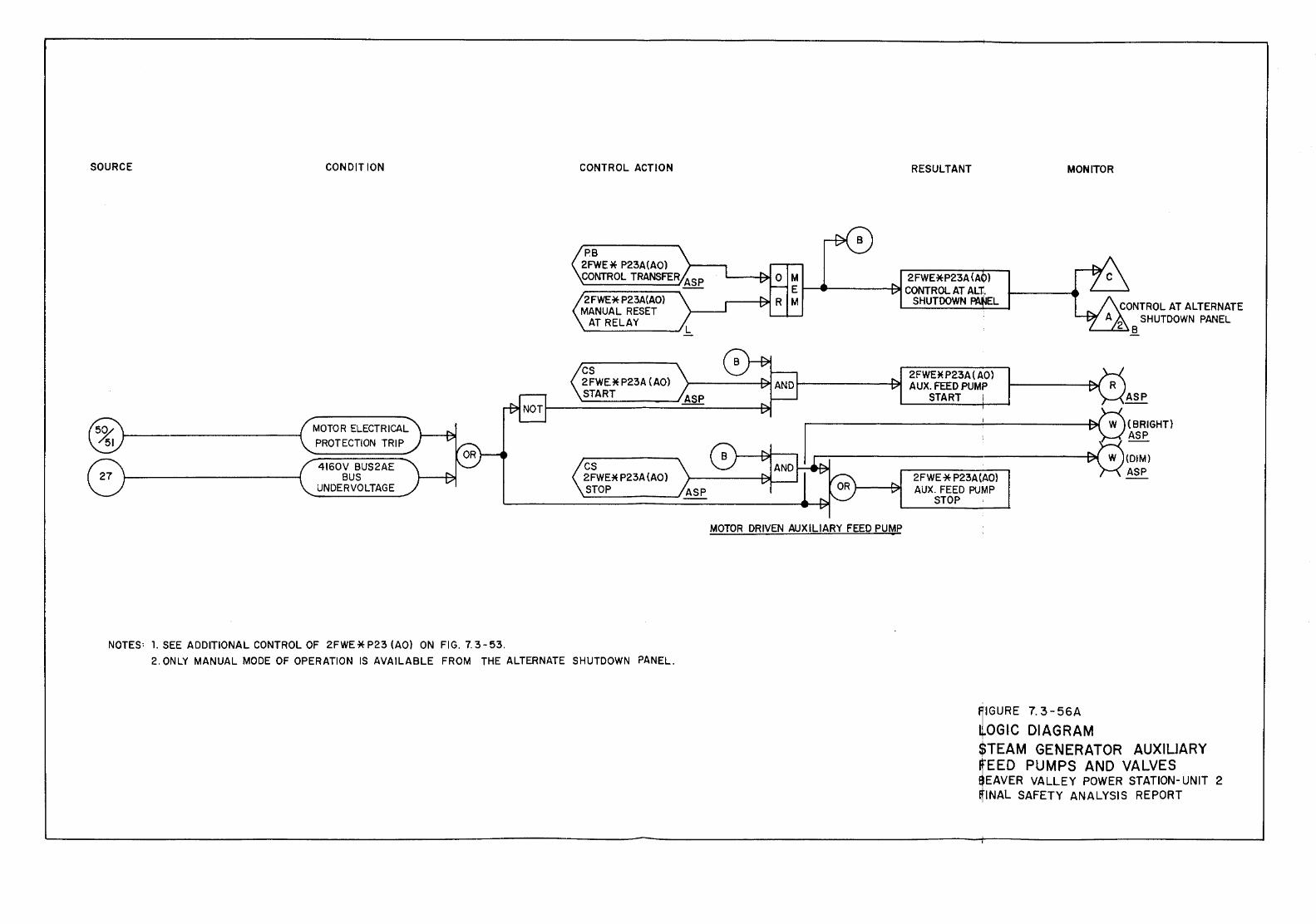
SOURCE CONDITION
MOTOR ELECTRICAL PROTECTION TRIP
4160V BUS2AE BUS
UNDERVOLTAGE
NOTES: 1. SEE ADDITIONAL CONTROL OF 2FWE*P23 {AO) ON FIG. 7.3-53.
CONTROL ACTION
PB 2FWE* P23A(AO) CONTROL TRANSFER ASP
2FWE*P23A(A0) MANUAL RESET
AT RELAY
cs 2FWE* P23A (AO) START
cs 2FWE* P23A {AO) STOP
2. ONLY MANUAL MODE OF OPERATION IS AVAILABLE FROM THE ALTERNATE SHUTDOWN PANEL.
RESULTANT MONITOR
2FWE*P23A(A ) 1-------------Pll CONTROL AT ALT.
SHUTDOWN . EL
2FWE * P23A ( AO) AUX. FEED PUMP
START
CONTROL AT ALTERNATE A
2 SHUTDOWN PANEL
'----L.::::..l B
ASP
W (BRIGHT)
- ASP r--:------------------e. W {DIM)
MOTOR DRIVEN AUXILIARY FEED PUMP
2FWE * P23A(AO) AUX. FEED PUMP
STOP
fiiGURE 7. 3- 56A
JoGIC DIAGRAM
ASP
$TEAM GENERATOR AUXILIARY
iEED PUMPS AND VALVES EAVER VALLEY POWER STATION- UNIT 2 INAL SAFETY ANALYSIS REPORT
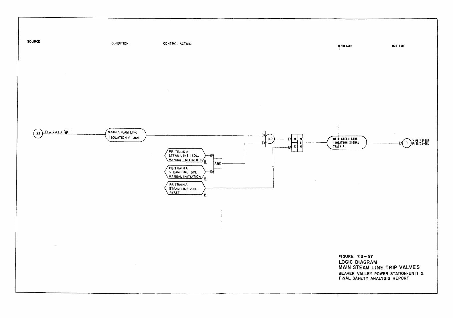
SOURCE:
0 FIG. 7.3-13 fj
CONDITION
MAIN STEAM LINE
ISOLATION SIGNAL
CONTROL ACTION
PB TRAINA STEAM U NE I SOL. MANUAL INIT!ATION
PB TRAIN A STEAM LINE ISOL. MANUAL INITIATION
PB TRAINA STEAM LINE ISOL.
'-'R~E::.::S:.:.ET.!.-.---.J a
R~SULTANT
MAll STEAM LINE ISO~TION SIGNAL TRA ~ N A
FIGURE 7.3-57 LOGIC DIAGRAM
,MOfriiTOR
MAIN STEAM LINE TRIP VALVES BEAVER VALLEY POWER STATION-UNIT 2 FINAL SAFETY ANALYSIS REPORT
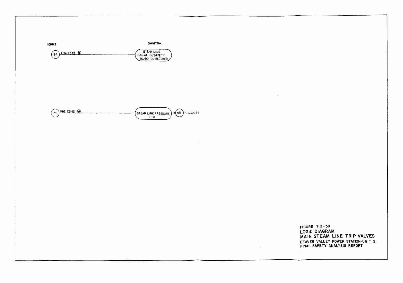
SOURCE CONDITION
STEAM L1NE ~=..~.~.:K:...Lfio._.::u.:....__ _________ --1 I SOLATION/SAFETY
INJECTION BLOCKED
G FIG. 7.3-12 ®
FIGURE 7.3-58 LOGIC DIAGRAM MAIN STEAM LINE TRIP VALVES BEAVER VALLEY POWER STATION-UNIT 2 FINAL SAFETY ANALYSIS REPORT
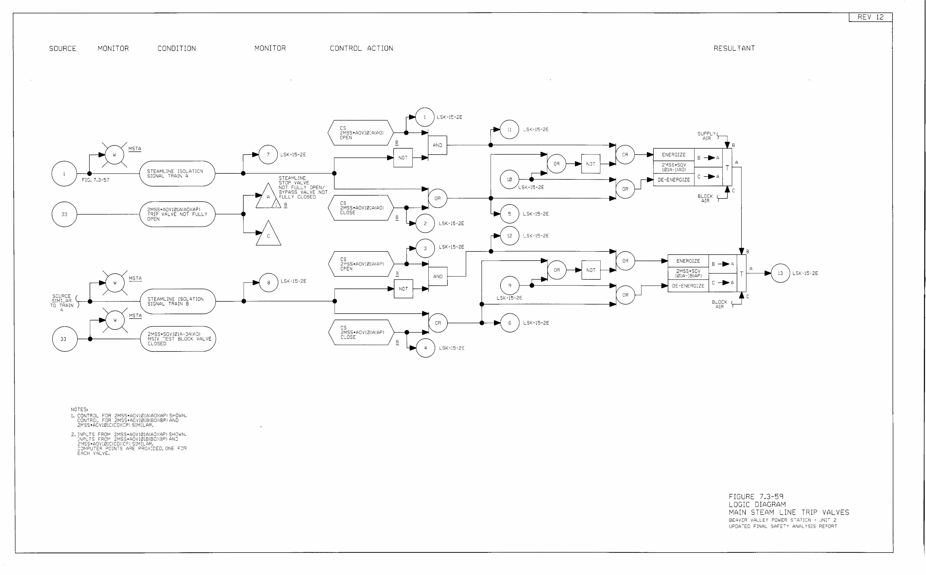
SOURCE MONITOR CONDITION
- MSTA
~ '1'1
STEAMLINE ISOLATION 1 SIGNAL TRAil\ A FIG. 7.3-57
2MSS •AOV 101A:AOIIAPI 33 TRIP VALVE NOT FULLY
OPO:N
-MSTA
~ w
-SCURCE ( SWILA;::: ) STEAM'-lNE ISOLATION - SIGNAL TRAIN B 0 TRAIN T
A
33
MSTA ... - w
2"1SS •SO V 101 C;- 3A:AOI MSIV TEST BLOCK VALVE CLOSED
NOTES: 1. CONTROL FOR 2MSS•AOV101A:AOIIAPI SHOI-IN.
CONTROL FOR 2MSS•AOV 101BIBOIIBPI AND 2MSS•AOV101CICOIICPI SIMILAR.
2. 1\JFUTS "ROM 2MSS•AOV101AIA0)(API SH0 1tJN. 1\JPUTS "ROM 2MSS•AOV101BIBOIIBPI AND 2MSS•AOV101CICOIICPI SIMILAR. COMPUTER POINTS A;:::E PROVIDED. 01\E FOR EACH VALVE.
MONITOR
... 7 LSK-15-2E -- STEAMLINE
STOP VALVE NOT FULLY OPEN/ BYPASS VALV:O: NJT
A FULLY CLOSED
1 B -
~ L,
.. LSK-15-2E 8 -
CONTROL ACTION
-~ 1 LSK-15-2E
cs -... 2MSS•AOV 101Aif\OI - -OPEN B AND -
• .. NOT ..
.. ... I/-OR
cs •I"-_ 2MSS•AOV101AI AOl CLOSE
B -~ 2 LSK-15-2E
~ 3 LSK-15-2E
cs 2 "1 SS • AOV 101 AI A PI • OPEN
B - AND .. __., .. NCT
• ... ..... / OR cs " .... 2MSS • f\OV 101AIAPI .....
CLOSE B -~ 4 I LSK-15-2E
-
-~ 11 LSK-15-2E
- ./ ... OR .. v " ... ... OR .... NOT -~I"-:0 .... - .... / - LSK-15-2:0: OR .. 1"-..... .. 5 LSK-15-2E -
~ 12 I LSK-15-2E
.... - -1/ ·/- OR
1"-)--------. ... OR NOT .... "-9 ./
LSK-15-2E OR
" ... ---.( 6 LSK-15-2E
-
... ....
.... J-
w
RESULTANT
SUPPLY I AIR
J f B
ENE"lGIZE B .. A A 2MSS•SOV T 101A-[(A01
DE-ENERGIZE c .. A
BLOCK 1 'C AIR
.. ENERGIZE -2MSS•SOV
101A-1BIAPI
• DE -ENERGIZE
)
ts B .. A
A T .... 13 - LSK-15-2E
c .. A
~ ~ c BLOCK c
AIR )
FIGURE 7,3-59 LOGIC DIAGRAM MAIN STEAM LINE TRIP VALVES BEAVER VALLEY ~owE;:: STATIO\J - UNIT 2 UPDATED FINC.L Sf\FETY ANALYSIS REPORT
REV 12
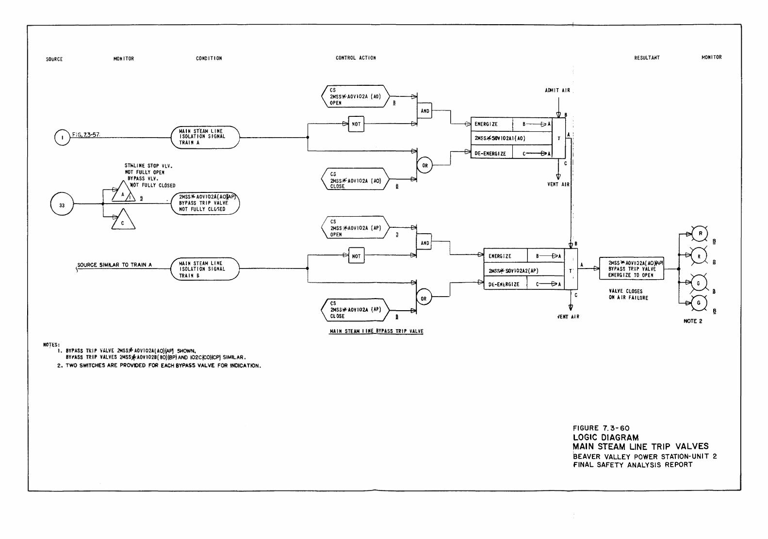
SOURCE
NOT!::S:
FIG 7.3-57.
MONITOR
ST~LINE STOP YLY. NOT FULLY OPEN
BYPASS VLY, •or FULLY CLOSED
\SOURCE SIMILAR TO TRAIN A
COHO ITI ON
MAIN ST'EAM LINE ISOLATION SIGNAL TRAIN A
2MSS *'- AOV 1 02A ( AOlAP BYPASS TRIP VALVE NOT FULLY Clu'iED
MAIN STEAM Ll NE I SOLA Tl ON SIGNAL TRAIN S
. I. BYPASS Tl\ I P ~·ALVE 2MSSJf< AOV102A( AO)lAP) SHOWN, BY I' ASS TRIP VAL YES 2MSS* AOV I 028 ( BO)\BP} AND 102C/CO)ICP) SIMILAR •
2. TWO SWITCHES ARE PROVDED FOR EACH BYPASS VALVE FOR INDICATION.
CONTROL ACTION
cs 2MSS~AOV102A (AO} OPEN
cs 2MSS~AOV102A {AO) CLOSE
cs 2MSS*AOV102A (AP} OPEN
cs 2MSS*AOVI02A {.~P) CLOSE
MAIN STEAM I.INE BYPASS TRIP VALVE
RESULTAiH HONITOR
AIJt.tiT AIR
8 B--+~ {>A
2MSS~SOV102Al{AO) A:
T
E>A DE-ENERGIZE c---+~
c
VENT AIR
ENERGIZE B~A
2MS~ SOYI02A2( AP)
0£ -ErkRG I ZE C~A
I
B
A
c
2.14SS )llc AOY I 0 2A( AO W'.PI BYPASS TRIP VALVE EPIERGIZE TO OPEN
VALVE CLOSES ON AIR FAILURE
B
iE!fT AIR
FIGURE 7. 3-60 LOGIC DIAGRAM
NOTE 2
MAIN STEAM LINE TRIP VALVES I
SEAVER VALLEY POWER STATION-UNIT 2 FINAL SAFETY ANALYSIS REPORT
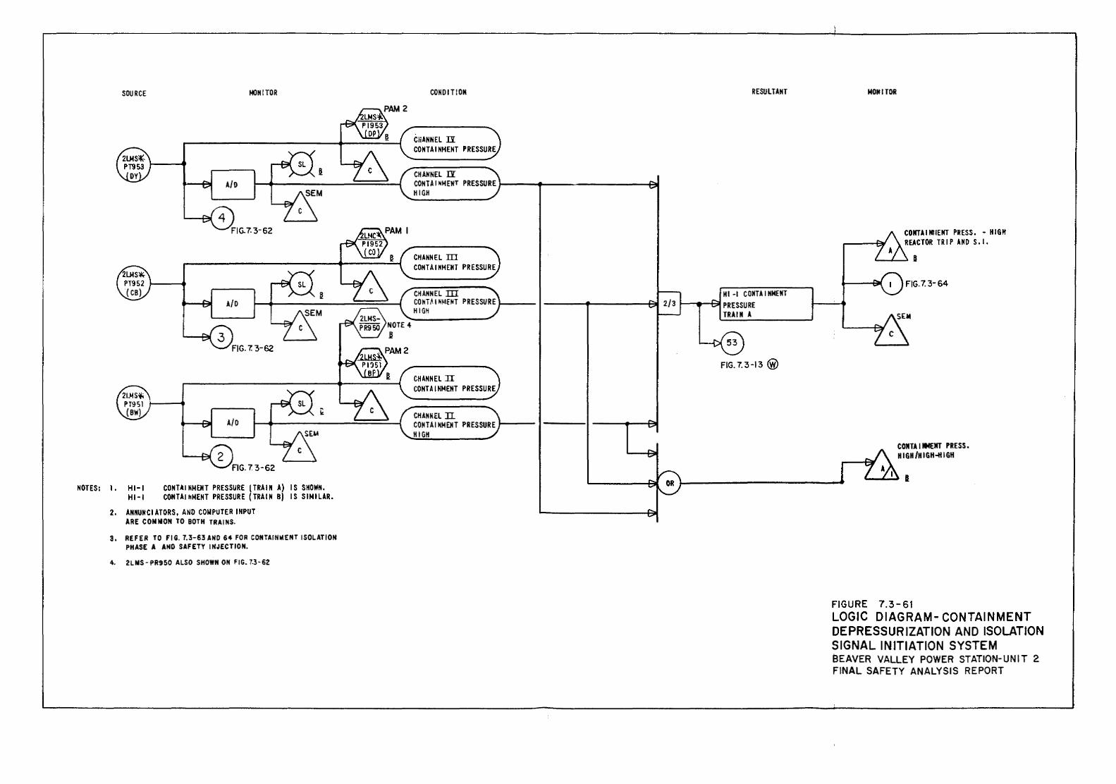
SOURCE
NOTES: 1. HI-I HI-I
MONITOR
CONTAINMENT PRESSURE {TRAIN A) IS SHOWN. CONTAI~MENT PRESSURE (TRAIN B) IS SIMILAR.
2. ANNUNCIATORS, AND CO!IPUTER INPUT ARE CONNON TO BOTH TRAINS.
3, REFER TO FIG. 7.3-63ANO 64 FOR CONTAINiotENT ISOLATION PHASE A AND SAFETY INJECTION.
4. 2LMS-PR950 ALSO SHOWN ON FIG. 7.3-62
CONDITION
CHANNEL ll CONTAINMENT PRESSURE
CHANNEL IY CONTAINMENT PRESSURE!----+---~-----~ HIGH
CHANNEL III CONTAINMENT PRESSURE
CHANNEL ill CO NT~ I N'-lfNT PRESSURE I----HIGH
CHANNEL ll CONTAINMENT PRESSURE
CHANNEL ll CONTAII!!MEHT PRESSURE I----HIGH
RESULTANT
HI -1 CONTAINMENT .....__..,._~PRESSURE
TRAIN A
FIG. 7.3-13@)
MONITOR
COIITAINIIENT PRESS. - HIGH REACTOR TRIP AND S.l.
FIG.7.3-64
COMTAINMEIT PRESS. HIGH/HIGH~IGH
I
FIGURE 7.3-61 LOGIC DIAGRAM- CONTAINMENT DEPRESSURIZATION AND ISOLATION SIGNAL INITIATION SYSTEM eEAVER VALLEY POWER STATION-UNIT 2 FINAL SAFETY ANALYSIS REPORT
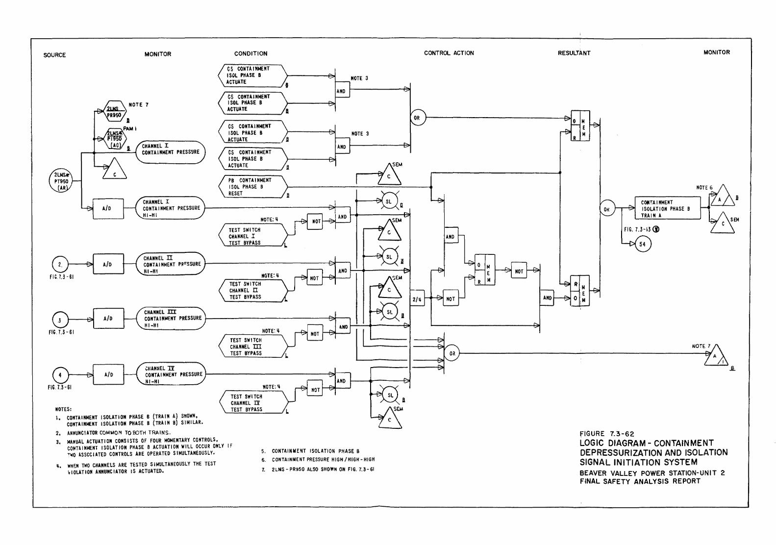
SOURCE MONITOR
CHANNEL I CONTAINMENT PRESS~RE
CONDITION
C S CONTA 1 NMENT !SOL PHASE B ACTUATE
CS CONTAINMENT !SOL PHASE B ACTUATE
CS CO NTA I NMEMT ISOL PHASE 8 ACTUATE
CS CONTAINMENT ISOL PHASE B ACTUATE
CONTROL ACTION
NOTE 3
NOTE 3
r----el~llf
< PB CONTAINMENT ), L~ ISOL PHASE 8 >--------__:_ __ ..=:==~---~
.._RE_S_ET ____ -..J B CHANNEL I
A/0 CO NTA I NMEMT PRESSURE 1-----------------f~----, HI-HI
CHANNEL n A/D CONTAINMEMT PR~SSURE
HI-HI FIG. 7.3 -SI
CHANNEL m A/D COMTAIN~ENT PRESSURE
HI-HI FIG.7.3 -SI
CHANNEL II A/D CONTAINMENT PRESSURE
HI-HI FIG. 1.3-61
NOTES: I, CONTAINMENT ISOLATION PHASE 8 {TRAIN A) SHOWN,
CONTAINMENT ISOLATION PHASE B (TRAIN B) SIMILAR. 2, .~NNUNCIATOR COMMON TO BOTH TRAINS.
NOTE:Ii TEST SWITCH CHANNEL I TEST BYPASS
NOTE:Ii TEST SWITCH CHANNEL II TEST BYPASS
NOTE:Ii TEST SWITCH CHANNEL ID TEST BYPASS
NOTE:Il TEST SWITCH CHAHNEL 1Y TEST BYPASS
3, MANUAL ACTUATION CONSISTS OF FOUR MOMENTARY CONTROLS, CONTAINMENT ISOLATION PHASE B ACTUATION WILL OCCUR ONLY IF TWO ASSCCIATED CONTROLS ARE OPERATED SIMULTANEOUSLY. 5. CONTAINMENT ISOLATION PHASE 8
q, WH~N TWO CHANNELS ARE TESTED SIMULTANEOUSLY THE TEST ¥10LATION ANNUNCIATOR IS ACTUATED.
6. CONTAINMENT PRESSURE HIGH/ HIGH- HIGH 1. 2 LMS- PR950 ALSO SHOWN ON FIG. 1. 3-61
"' E M
RESULTANT MONITOR
CQfi:TA I MMENT ISOLATION PHASE B TRAIN A
FIG. 7. 3-13 (i'
FIGURE 7.3-62 LOGIC DIAGRAM- CONTAINMENT DEPRESSURIZATION AND ISOLATION SIGNAL INITIATION SYSTEM BEAVER VALLEY POWER STATION-UNIT 2 FINAL SAFETY ANALYSIS REPORT
_a_
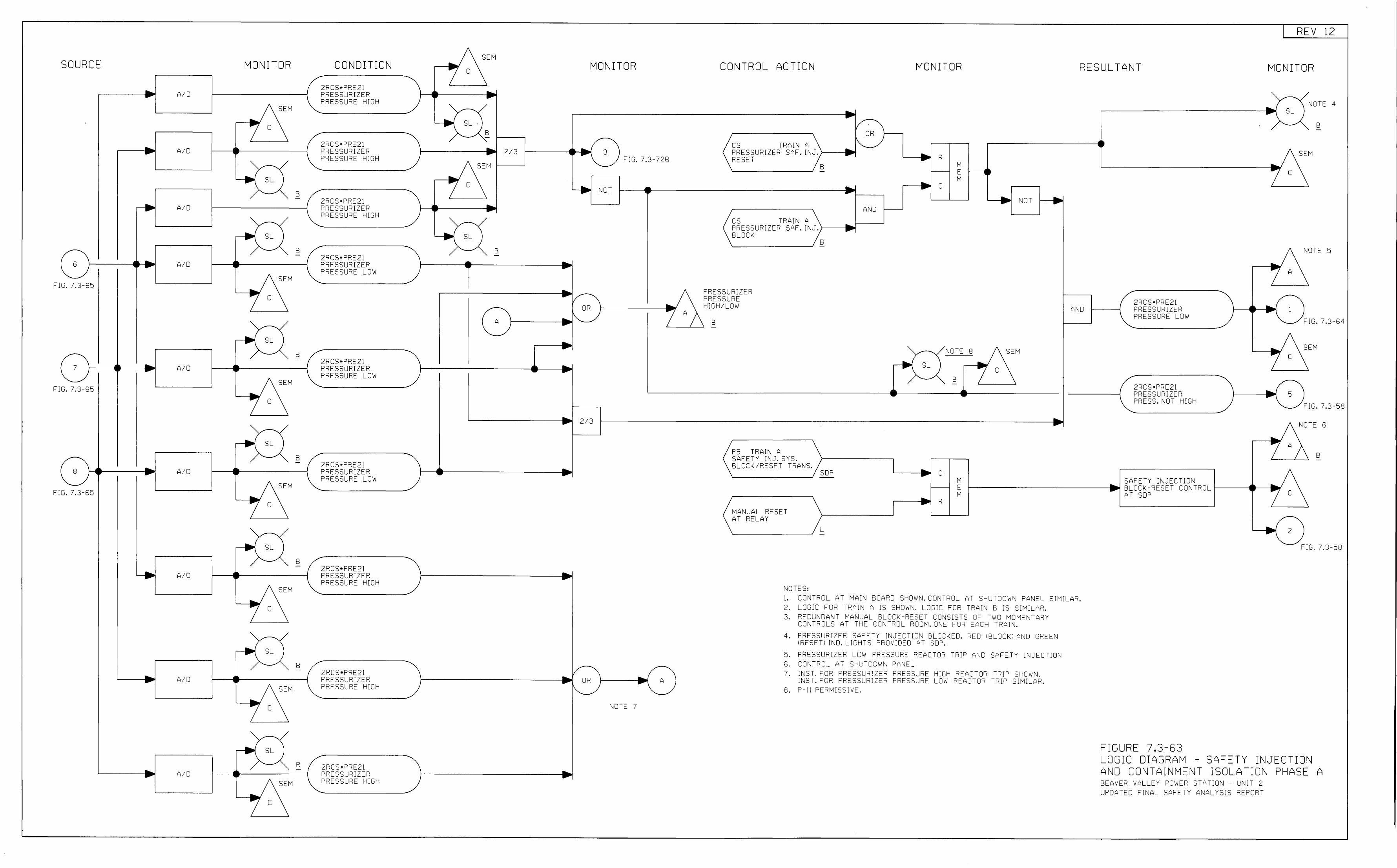
SOURCE
6
-FIG. 7.3-65
.. ....
,....-----·
_ .... -
7 I-----< I--· -
FIG. 7.3-65
8 r--.----· FIG. 7.3-65
..
A/0
A/0
AID
A/0
A/0
A/0
A/0
AID
A/0
MONITOR
...
... -__... ....
__... ....
• ..
SEM
SL
SL
SEM
SL
SEM
c
-SL
B
B
B
- B
SEM
c
~ SL I
.. ....
~
... 7
SEM
c
s_ J
SEM
c
-SL
SEM
c
B
B
B -
CONDITION
2RCS• 0 RE21 PRESSURIZER PRESSURE HIGH
2RCS•PRE21 PRESSURIZER PRESSURE HIGH
2R:::S•PRE21 PRESSURIZER PRESSURE HIGH
2RCS•PRE21 PRESSURIZER PRESSURE LOW
2RCS• 0 RE21 PRESSURIZER PRESSURE LOW
2'1CS•PRE21 PRESSURIZC::R PRESSURE L0 1tl
2RCS•PRE21 PRESSURIZER PRESSURE HIGH
2R:::S•PRE21 PRESSURIZER ?RESSURE HJ:::;H
2R:::S•PRE21 PRESSU'i!ZER PRESSURE -IIGH
REV 12
SEM
c MONITOR CONTROL ACTION MONITOR RESULTANT MONITOR
f---e---· S~ .
B -1-----· 2/3
SEM 1----.....J
c
~f-----·
__... ..... s:...
1-------e----------·
... -
... -
~---------------·1/-
0R
A 1-------•1""'--"
.. ... 1--------------~~-·
2/3
... ...
1------------------·
/ 1--------------------· OR
1"-_
..
.. ::: s T R A I \J A '---__..,I"-.. ~RESSURIZER SAF. INJ ., _.
F:G. 7.3-728 'lESE-;-B
... R ... M E M
NOTE 4 ~-----------------~ SL I
B
SEM
c \JOT ~~--------------------------------•r--,
... 0 ... __. f.-OT .. ...
...
AND
CS TRAil\ A PRESSURIZER SAF. INJ .}-----j~~---' BLOCK
PRESSU'i!ZER PRESSU'iE HIGH/LOW
B
B
NOTE 8
__.., S L I .... c B
?>NO
SEM
2RCS•PRE21 PRESSURIZER PRESSURE LOW
2RCS•PRE21 PRESSURIZER PRESS. NOT HIGH
NOTE 5
A
~------~ 1 - FIG. 7.3-6L
_ ... SEM
.... -rG. 7.3-58
~-----------------------------------------------· NOTE 6
-1-----~ A
NOTE 7
PB TRAI'J A SAFETY INJ. SYS. BLOCK/RESET TRANS.
SOP .... 0 -•
B
..., R -M c M
SAFETY INJECTION 1---------------1.,~ BLOCK -RESC: T CONTROL 1-------j r--_...z_,. C
.... AT SOP
MANUAL RESET AT RELAY
L
NOTES: 1. CONTROL AT MAIN BCARD SHO'tiN. CONTROL A- SHL. TJOWI\ PANEL SIMILAR. 2. LOGIC FOR TRAIN A IS SHOWN. LOGIC FOR TRAIN B IS SIMI:...AR. 3. REDGNDANT MANUAL BLOCK-RESET CONSISTS OF TWO MOMEI\TARY
CONTROLS AT THE CON-ROL RCOM,ONE FOR EA:::H TR?>If.-.
4. PRESSURIZER SAFC:TY INJEc-;oN BLOCKC:D. RED (BLOCK! AND GREC:N (RESET! IND. LIGHTS "ROV:DED AT SOP .
:::1. PRESSURIZER LOW PRESSURE RE?>CTOR TRIP AND S?>F::TY INJECTION 6. CONTRCL AT SHUTCOWN P<'\~1EL
7. INST. FOR ~RC:SSURIZER PReSSURE HIGH R:O?>CTCR TRIP SHOWN. INST. FOR PRESSURIZE'i PRESSURE LOW REACTOR TRIP SIMILAR.
8. P-11 PERM:SSIVE.
- FIG. 7.3-58
FIGURE 7.3-63 LOGIC DIAGRAM - SAFETY INJECTION AND CONTAINMENT ISOLATION PHASE A BEAVER VALLEY ~OWER STATIO'J - UNIT 2 UPDATED FINAL SA"ETY ANALYSIS REPORT
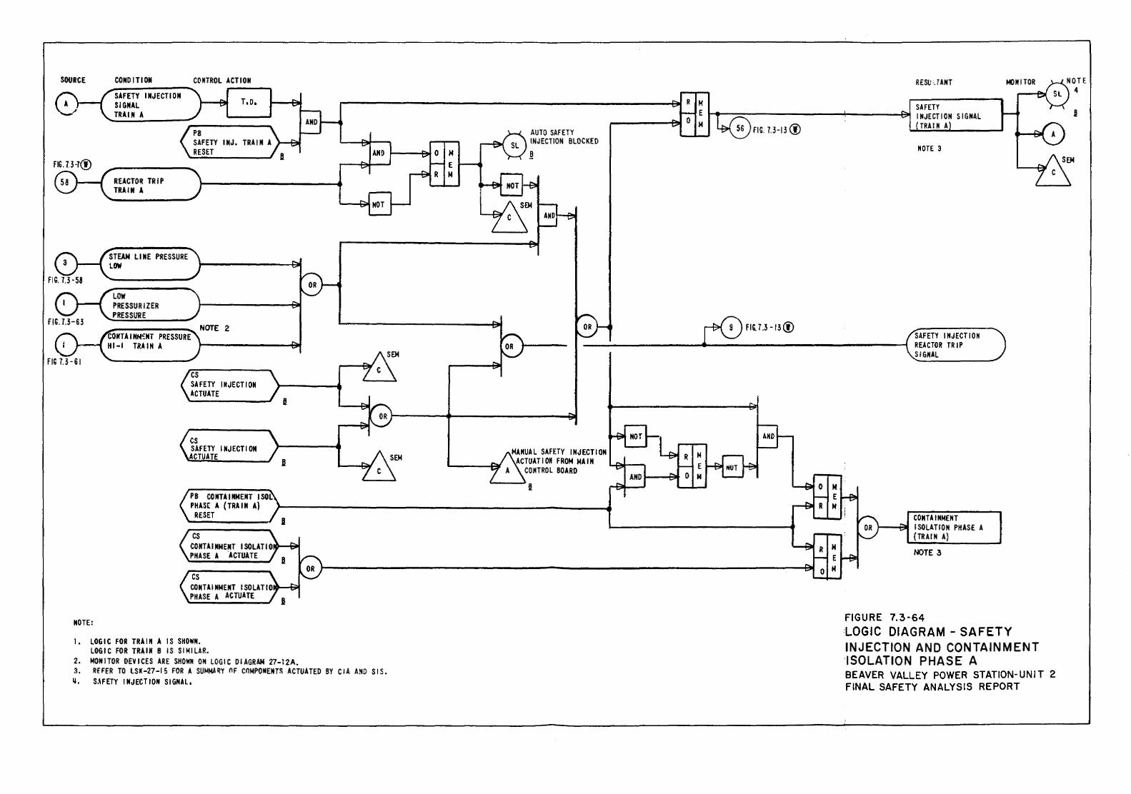
SOURCE
NOTE:
CONDITION SAFETY INJECTION SIGNAL TRAIN A
REACTOR TRIP TRAIN A
STEAM LINE PRESSURE LOW
LOW PRESSURIZER PRESSURE
CONTROL ACTION
T,D,
PB SAFETY INJ. TRAIN A RESET
CONTAIHN~NT PRESSURE HI-I TRAIN A
cs SAFETY INJECTION ACTUATE
cs SAFETY INJECTION
ACTUATE
PB CO NTA I NNENT I SOL: PHAS( A (TRAIN A)
RESET
cs CONTAINMENT ISOLATIO PHASE A .ACTUATE
cs CONTAINMENT ISOLATIO PHASE A ACTUATE
t. LOGIC FOR TRAIN A IS SHOWN. LOGIC FOR TRAIN B IS SI~ILAR.
2. ~ONITOR DEVICES ARE SHOWN ON LOGIC DIAGRAM 27-l2A. 3. REFER TO LSK-27-15 FOR A SU~MA~Y OF COMPONENTS ACTUATED BY CIA AND SIS. ". s.\FETY r HJECTION sr GNAL.
AUTO SAFETY INJECTION BLOCKED
~
MANUAL SAFETY INJECTION ACTUATION FROM MAIN
CONTROL BOARD
FIG. 7.3- !3 (!)
RESU·.U.NT
MOTE 3
SAFETY INJECTION REACTOR TRIP SIGNAL
CONTAINMENT 1--"""""t'lfl I SOLATION PHASE A
{TRAIN A)
NOTE 3
FIGURE 7.3-64
MONITOR
LOGIC DIAGRAM - SAFETY INJECTION AND CONTAINMENT ·ISOLATION PHASE A BEAVER VALLEY POWER STATION-UNIT 2 FINAL SAFETY ANALYSIS REPORT
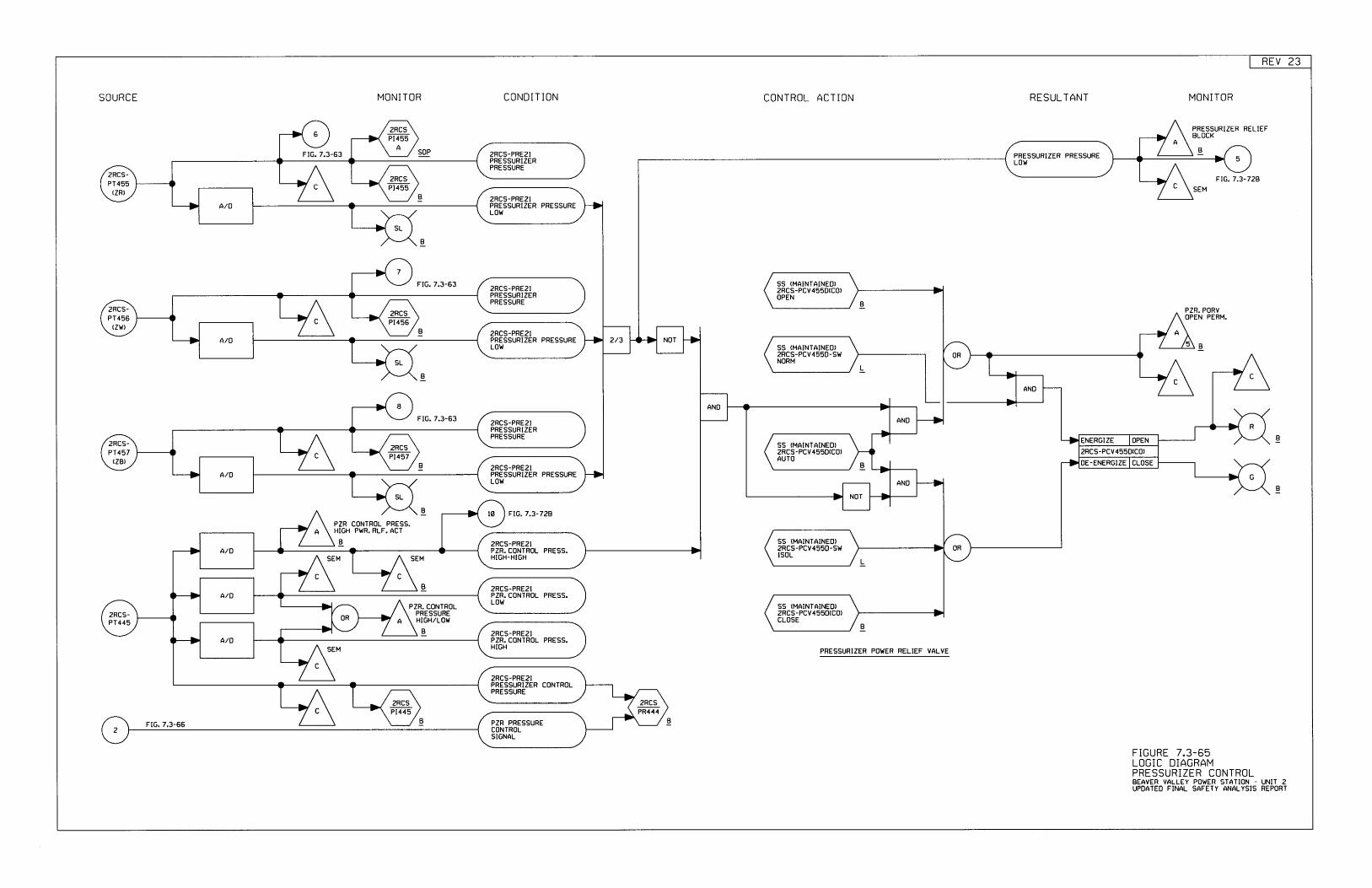
REV 23
55 IMAINTAINEI])zRCS-PCV455D-SWNORM
2RC5PH55
APEESSURIZER PEESSUREL0W
2HCS-PRE2IPRESSURIZERPRESSURE
?RCS-PT455
(ZRI
zRCSPI455
A/O2RCS-PREZIPRESSURIZER PRESSUREL0W
55 (HAINTATNEOI2RCS-PCV455D{C0)OPEN
2RCS-PRE2IPRESSURIZERPRESSURE
PI456zRCS2RCS-
PT456(zt{)
?/3 NOTAlO2RCS-PRE2IPRESSURIZER PRESSUREL0r{
ANO
AND
ANT]
ENERGIZE OPEN
2RCS-PRE2IPRESSURIZERPRESSURE
zRCS-PCV45sD(C0r
I]E-ENERGIZE ELOSE
SS (MAINTATNEOI2RC5-PCV455D(80)AUTO
2RCS-PT457
(ZB}
zRcsPI457
A/02RCS-PREzIPRESSURIZER PRESSUREL0h, ANI]
NOT
SS (MAINTAINET])2RCS-PCv4550-SWISOLAlD
2RCS-PRE2IPZE, CONTROL PRE55.HIGH-HIGH
A/O2RCS-PRE2IPZR. CONTROL PBESS.L0w S5 IMAINTAINET])
2RCS-PCV455D(E0rCLOSE
2FCS-PT445
HIGH
2RE5-PREZIPZR. CONTROL PRESS.A/O
2RCS-PRE2IPRESSURIZER CONTROLPRESSURE
2RC5PT445
PZR PRESSURECONTROLSIGNAL
SOURCE MONI TOR CONDIT ]ON CONTROL ACTION RESULTANT MONITOR
PHESSURIZEH RELIEFgLOCK
FIG. 7.3-63 SDP B
FIG. 7.3-728SEM
E
B
FI0. 7.3-63
sPZR. PORVOPEN PERM.
B
B
LB
FIG. 7.3-63
E
B FtG.7.3-725PZR CONTROL PRESS.HIGH PWR. RLF. ACT
B
SEM SEM L
B
PZR. CONTROLPRESSUREHIEH/LOW
E.E.
SEM PRESSUBIZER POT{ER RELIEF VALVE
B B
FIGURE 7.3-65LOGIC DIAGRAMPRESSURIZER CONTROLBEAVER VALLEY POWER STATION - UNIT 2UPI]ATED FINAL SAFETY ANALYSIS REPORT
FIG. 7.3-56
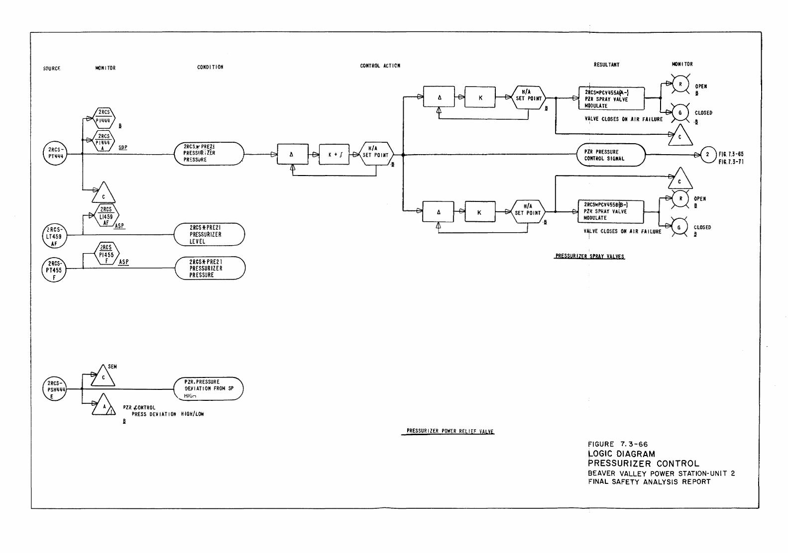
SOURCE MONITOR
B
SOP
PZR ~OHTROL
CONDITION
2RCSJr PRE2J p RESStfk"i UR PR~SS\JRE
2RCSHRE21 PRESSURIZER LEVEL
2RCS* PRE21 PRESSURIZER PRESSURE
PZR. PRESSURE DEYIATION FROM SP HIG,.-,
PRESS DEY I AT I OM K I Gil/LOW
CONTROL ACT I CN
K
K + I
K
PRESSURIZER POWER RELIEF VALVE
~ESULTANT
2RCSHPCV1155A"-} PZR SPRAY VALVE NODULATE
PZR PRESSURE CONTROL SIGNAL
2RCS*PCV"55B{B-J PZif SPiiAY YAi..VE MODULATE
PRESSURIZER SPBAY VALVES
FIGURE 7. 3-66
I«<NITOR
OPEH j
CLOSED
·a
OPEN j
CLOSED ~
J_OGIC DIAGRAM PRESSURIZER CONTROL
FIC. 7.3-65 FlU.3-71
BEAVER VALLEY POWER STATION-UNIT 2 FINAL SAFETY ANALYSIS REPORT
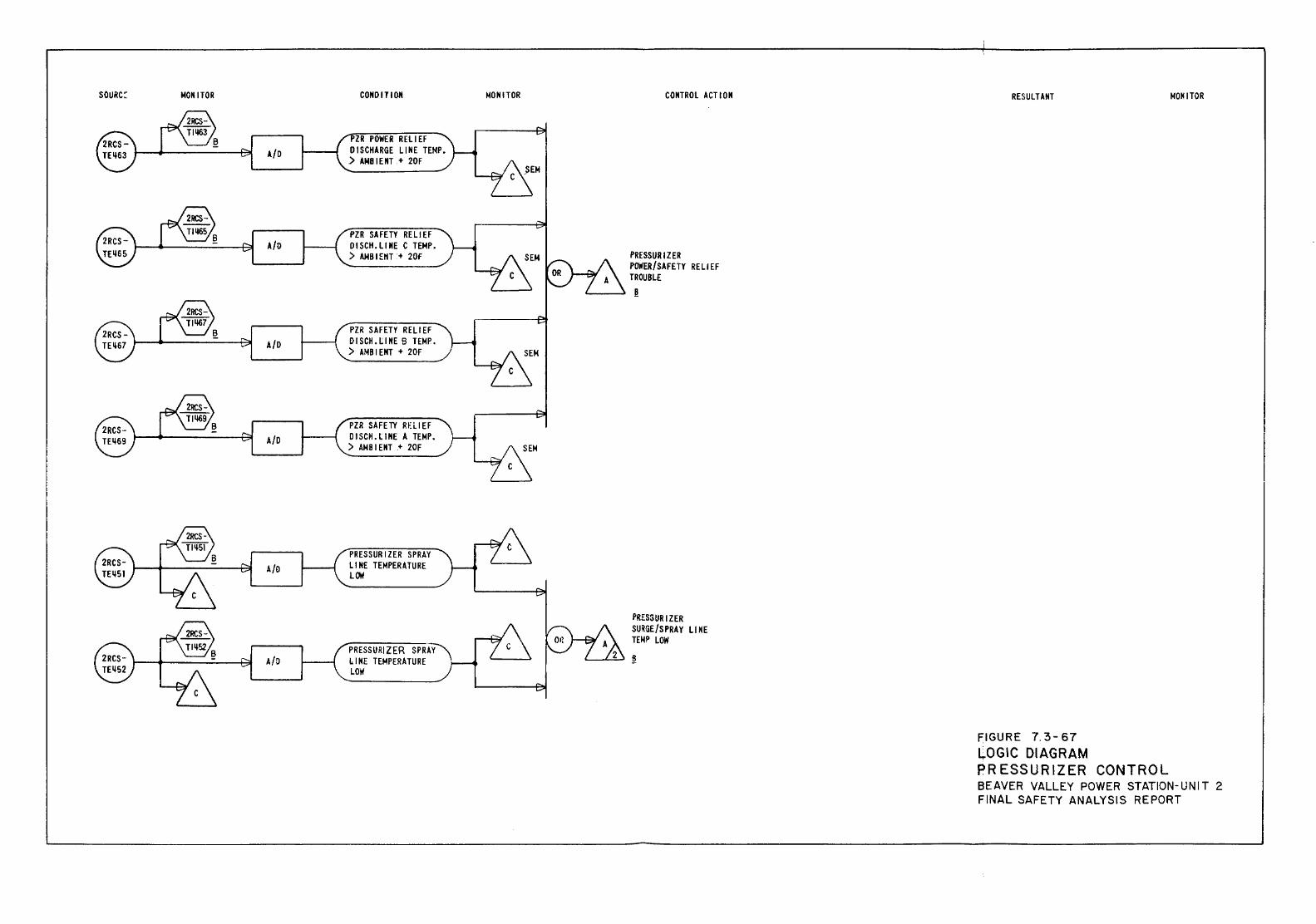
SOURC~ MONITOR
A/0
A/D
A{O
A/0
A/0
A/0
CONDITION
ZR POWER RELIEF DISCHARGE LINE TEMP. ) AMBIENT + 20F
PZR SAFETY RELIEF OISCH.LINE C TEMP. ) AMBIEIH + 20F
PZR SAFETY RELIEF DISCH. t; I NE B TEMP. ) AMB I ENT + 20F
PZR SAFETY RF.LIEF OISCH.LINE A TEMP. ) AMBIENT + 20F
PRESSURIZER SPRAY LIME TEMPERATURE l~
PRESSURIZER SPRAY LIME TEMPERATURE LOW
MONITOR CONTROL o\CTI 0 N
PRESSURIZER POWER/SAFETY RELIEF TROUBLE ~
PRESSUR I ZER SURGE/SPRAY Ll NE TEMP LOW
'--..L-:-" ft
RESULTANT
FIGURE 7. 3-67 LOGIC DIAGRAM PRESSURIZER CONTROL
MONITOR
BEAVER VALLEY POWER STATION-UNIT 2 FINAL SAFETY ANALYSIS REPORT
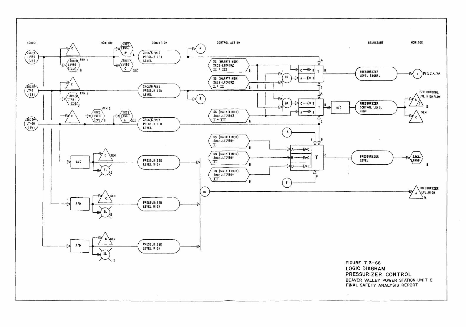
MONITO~
PAM I
A/D
A/D
A/D
COMO IT I ON
2RCS*-PRE21 PRESSURIZER LEVEL
2RCS¥PRE.21 PRESSURIZER LEVEL
2RCS*"RE21 PRESSURIZER LEVEL
PRESSUR \ZER LEVEL HIGH
PRESSURIZER LEVEL HIGH
PRESSURIZER LEVEL HIGH
CONTROL ACT I ON
SS (MAINTAIKED) 2RCS -L T0ij59Z rr • m SS (MA I MTA I NED) 2RCS-LTOij59Z I+ II
SS (MAINTAINED) 2RCS-LTOij59Z I+ III
SS (MAINTAINED) 2RCS- LTOij59Y I
SS (~IAINTAINED) 2RCS-LTD~59Y TI
SS (MA I NUl NED) 2RCS- L TD't59Y .lli
A
B
c
A/0
c
A 8
I>C f;.!oC T c
E>C
D
RESULTANT MOIHTOR
PRESSURIZER LEVEL S 1 GNA L
PRESSUR I Z ER CONTROL LEVEL HIGH
PRESSURIZER LEVEL
FIGURE 7. 3-68 LOGIC DIAGRAM PRESSURIZER CONTROL
~ Fl G.7.3-75
PZR CONTROL LVL HIGH/LOW
8
8
BEAVER VALLEY POWER STATION-UNIT 2 FINAL SAFETY ANALYSIS REPORT
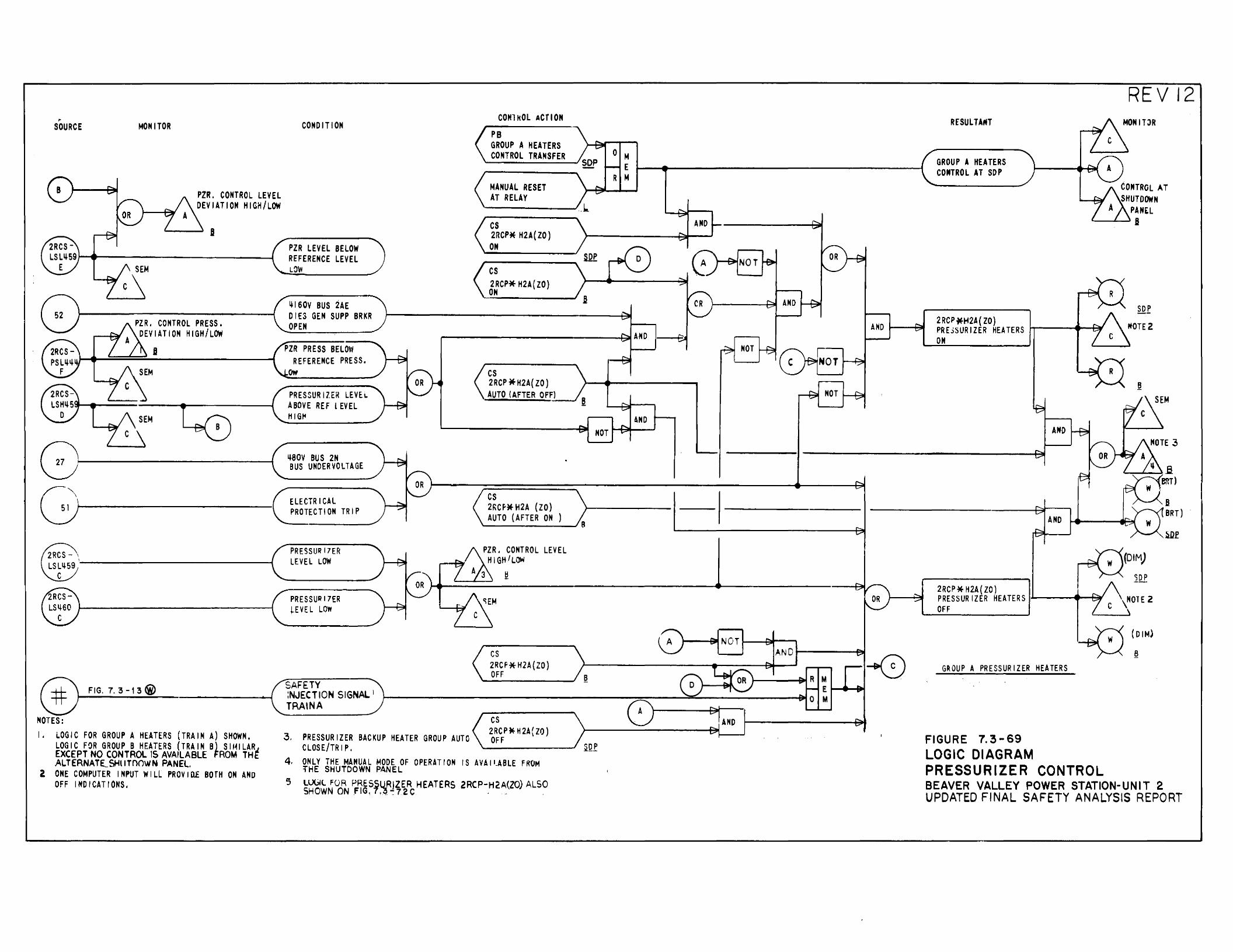
,. SOURCE MONITOR
PZR. CONTROL LEVEL DEVIATION HIGH/LOW
PZR. CONTROL PRESS. DEVIATION HIGH/LOW
8
CONDITION
PZR LEVEL BELOW REFERENCE LEVEL LO~
iji60V BUS 2AE DIES GEN SUPP BRKR OPEN
PZR PRESS BELOW REFERENCE PRESS.
ow
PRESSURIZE~ LEVEL ABOVE REF LEVEL HIG~
CONli<O L ACT I ON PB GROUP A HEATERS CONTROL TRANSFER
MANUAL RESET AT RELAY
cs 2RCP* H2A( ZO)
ON
cs 2RCP* H2A{ ZO) ON
cs 2RCP * H2A( ZO) AUTO (AFTER OFF)
r:"\, ij80V BUS 2N ~~---------------------------~ '-B-US __ U_ND_E_Rv_o_LT_A_G_E~
G\ ELECTRICAL 51 ~---------------------------1 ,_P_R_OT--E-CT_I_OH--TR_I_P __
cs 21\Cf*H2A (ZO) AUTO (AFTER ON
FIG. 7. 3 -1 3@)
NOTES: I, LOGIC FOR GROUP A HEATERS (TRAIN A) SHOWN,
LOGIC FOR GROUP B HF.ATERS (TRAIN B) SII~ILAR~ EXCEPT NO CONTROL IS AVAILABLE (:ROM THt ALTERNATE._SHIITnC1WN PANEL.
2 ONE COMPUTER INPUT WILL PROVIO£ BOTH ON AND OFF INDICATIONS.
PRESSUR17ER LEVEL LOW
PRESSUR17ER ~EVE L LOW
SAFETY :NJECTION SIGNAL 1
TRAINA
PZR. CONTROL LEVEL HIGHILOW
A 3 ~
cs 2RCf*K2A(ZO) OFF
cs 2RCP*H2A(ZO)
3. PRESSURIZER BACKUP HEATER GROUP AUTO OFF CLOSE/TRIP. ~-------'
4, ONLY THE MANUAL MODE OF OPERATION IS AVAII.ABLE FROM l'HE SHUTDOWN PANEL
5 U.)(jll F()R PRESSUR]ZER HEATERS 2RCP-H2A(ZO) ALSO SHOWNONFIG,7,~~72C · - ·
NOT
NOT
UD NOT
R£SULTAfH
GROUP A HEATERS CONTROL AT SOP
2RCP*H2A{ ZO) PREiSURIZER HEATERS ON
AND
REV 12 MONITJR
CONTROL AT SHUTDOWN
PANEL .._ __ .8
~(DIM) I >---:' 2DP
.8 BRT)
2RCP*H2A{ZO) PRESSURIZER HEATERS I..L----..... --t'l OFF
G~OUP A PRESSURIZER HEATERS
FIGURE 7. 3-69 LOGIC DIAGRAM PRESSURIZER CONTROL BEAVER VALLEY POWER STATION- UNIT 2 UPDATED FINAL SAFETY ANALYStS REPORT
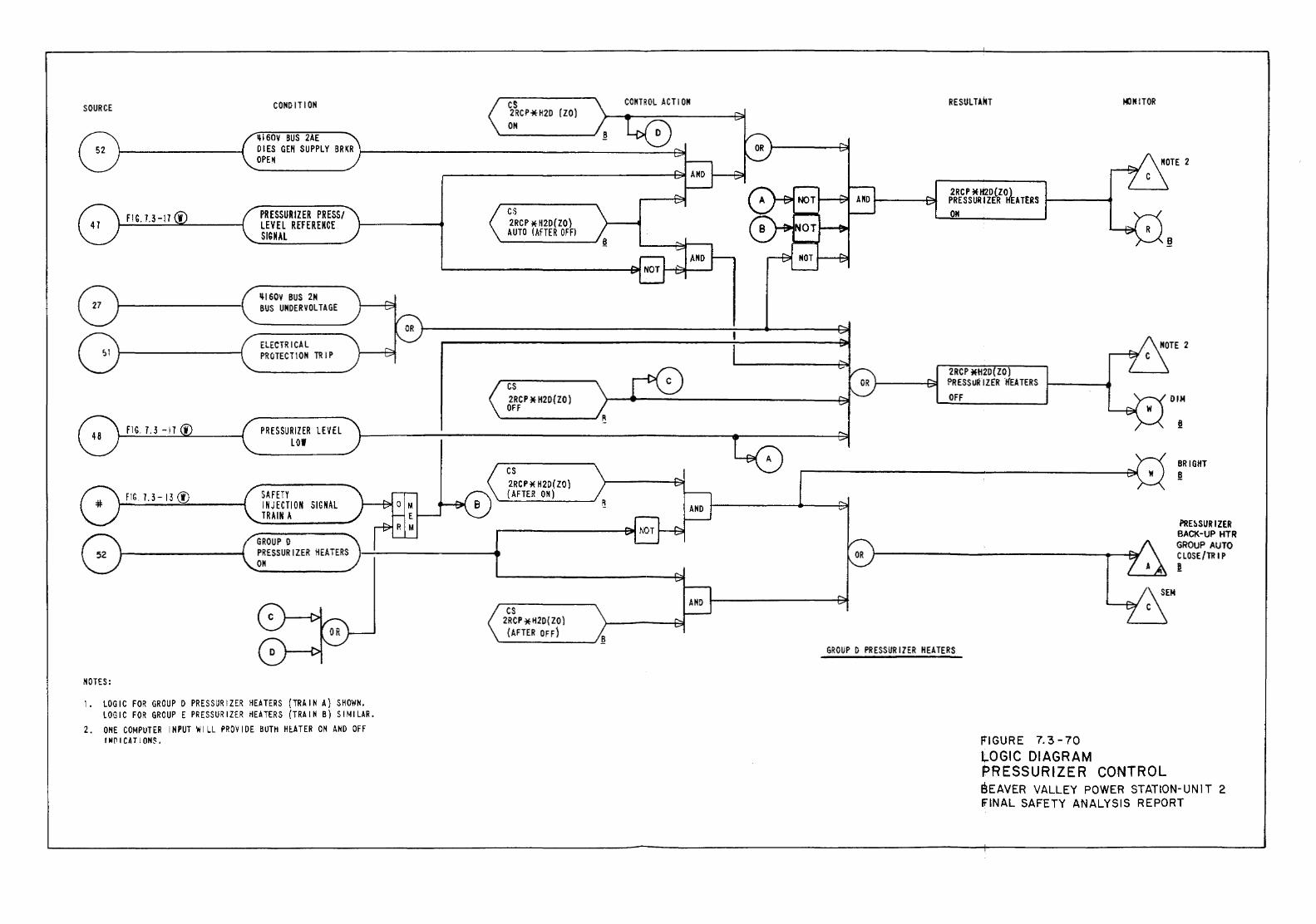
SOURCE
FIG. 7.3-13 <!)
NOTES:
CONDITION
!li60V SUS 2AE DIES GEH SUPPLY SRKR OPE~
PRESSURIZER PRESS/ LEVEL REFERENCE SIGNAl
ll160V BUS 2N BUS UNDERVOLTAGE
ELECTRICAL PROTECTION TRIP
PRESSURIZER lEVEL LOI
SAFETY INJECTION SIGNAL TRAIN A
GROUP 0 PRESSURIZER HEATERS OM
I. LOGIC FOR GROUP D PRESSURIZER HEATERS (TRAIN A) SHOWN. LOGIC FOR GROUPE PRESSURIZER HEATERS (TRAIN B) SIMILAR.
2. ONE COMPUTER INPUT WILL PROVIDE BUTH H~ATER ON AND OFF IN!liCATIONS.
cs 2RCP*K2D (ZO)
OM
cs 2RCP*H2D{ZO) AUTO (AfTER OFF)
cs 2RCP * H2D{ZO) OFF
cs
~
2RCP* H2D(ZO) (AFTER OM) ---.:. __ __.: __ ____~~
cs 2RCP * H20{ ZO)
(AFTER OFF) '--------".!!
RESULTA.IIT
2RC P * H2D (ZO.k PRESSURIZER ATERS OM
2RCP *H20 ZO) ?RESSlJR IZER "!(EATERS OFF
GROUP 0 PRESSURilER HEATERS
FIGURE 7. 3-70
1-CMITOR
LOGIC DIAGRAM PRESSURIZER CONTROL
BRIGHT §
PRE~SURIZER BACK-UP HTR GROUP AUTO CLOSE/TRIP ft
BEAVER VALLEY POWER STATION-UNIT 2 ltiNAL SAFETY ANALYSIS REPORT
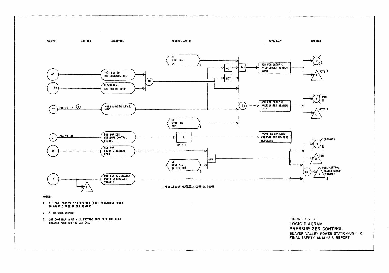
SOURCE J.eONITOR
0 FIG. 7.3-17 ®
MOTES:
CONDITION
1180Y 8US 2D BUS UNDERYOLTAGE
ELECTRICAL PROTf.CTiON TRIP
PRESSURIZER LEVEL LOW
PRESSURIZER PRESSURE CONTROL SIGNAL
ACB FOR GROUP C HEATERS OPEN
PZR CONTROL HEATER POWER CONTROLLER TROUBLE
I, S I LICON CONTROllED RECTI F I ER ( SCR) TO CONTROL POWER TO GROUP C PRESSURIZER HEATERS.
2. 11 BY WESTINGHOUSE.
3. ONE COMPUTER INPUT WILL PROYIOE BOTH TRIP AND CLOSE IREAKER POSITION INDICATIONS.
CONTROL ACTION
cs 2RCP-H2C ON
cs 2RCP-H2C OFF
K
NOTE I
cs 2RCP-H2C {AFTER ON)
PRESSURIZER HEATERS - CONTROL GRQUP
RESULTANT MONITOR
ACB FOR GROUP C PRESSURIZER HEATERS. f... ---41 CLOSE
~:IM ACB FOR GROUP c I~ PRESSURIZER HEATERS 1-----f TRIP
POWER TO 2RCP-H2C PRESSURIZER HEATERS NODULATE
FIGURE 7.3-71
{BRIGHT)
PZR, CONTROL HEATER GROUP
TROUBLE J
Lr.OGIC DIAGRAM PRESSURIZER CONTROL BEAVER VALLEY POWER STATION-UNIT 2 FINAL SAFETY ANALYSIS REPORT
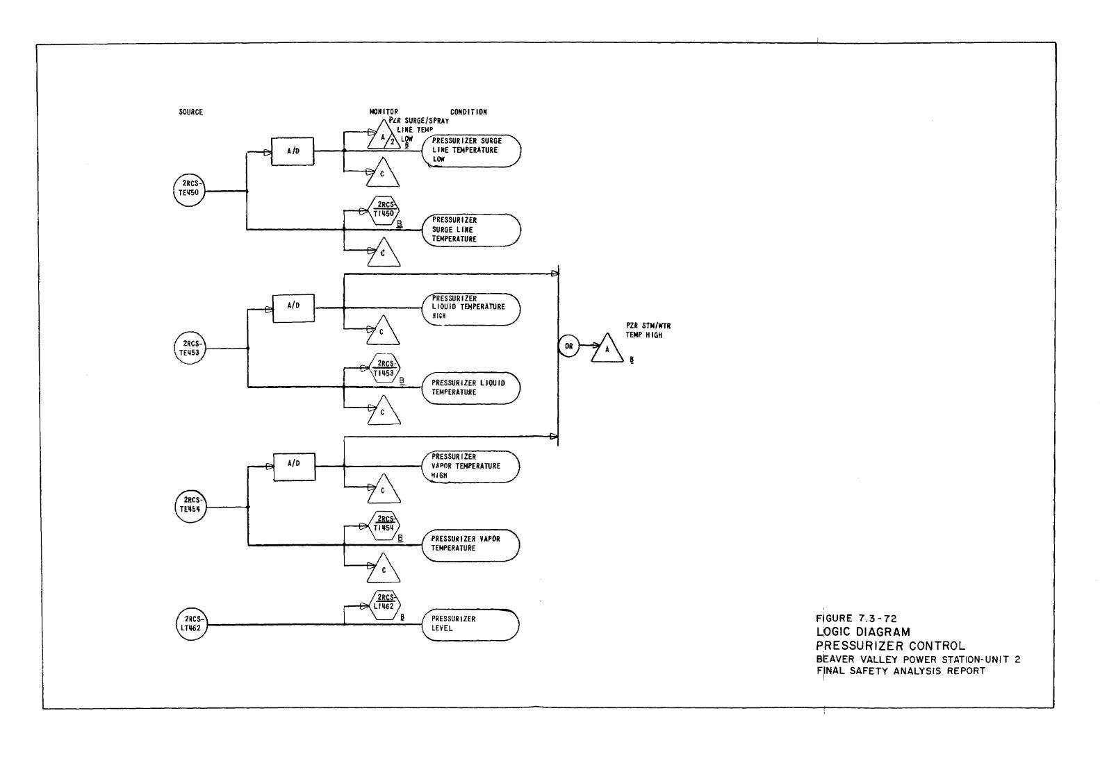
SOURCE
A/D
A/D
A/0
MOMITOR COMDITIOM ~LR SURGE/SPRAY
LIME TEioiP~------A 2 tgw PRESSURIZER SURGE
J---f--...=;;;;;;::;;;;::;:;!...;-~ ll NE TEMPERATURE LOW
PRESSURIZER SURGE LIME TEMPERATURE
PRESSURIZER LIOUJD TEMPERATURE HIGH
PRESSURIZER LIQUID TEMPERATURE
PRESSURIZER VAPOR TEMPERATURE IUGH
PRESSU~IZER VAPOR TEMPERATURE
PRESSURIZER LEVEL
PZR STN/WTR TENP HIGH
FIGURE 7.3-72 LOGIC DIAGRAM PRESSURIZER CONTROL BEAVER VALLEY POWER STATION-UNIT 2 F'NAL SAFETY ANALYSIS REPORT
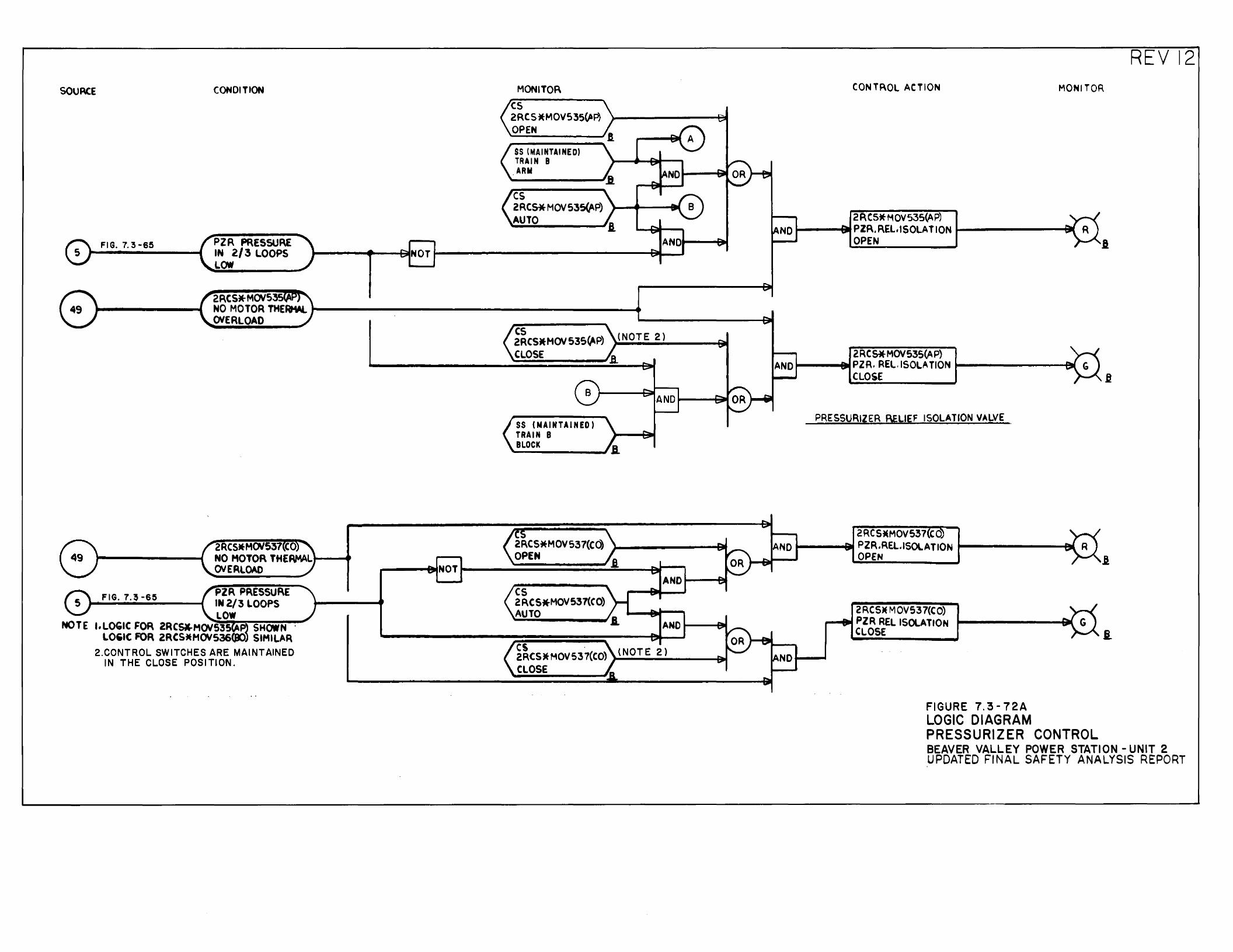
SOURCE CONDITION
FIG. 7. 3-65 PZR PRESSURE IN 2/3 LOOPS NOT LOW
NOT
PZR PRESSURE FIG. 7.~ -65 IN2/3 LOOPS LOW
NOTE I.LOGIC FOR 2RCStrHOVS3S ~ SHOWN · LO,IC FOR 2RCSttMOVS36(JK). SIMILAR
2.CONTROL SWITCHES ARE MAINTAINED IN THE CLOSE POSITION.
MONITOR cs 2RCS*MOVS35~P) OPEN
SS (MAINTAINED) TRAIN B ARM
cs 2RCS*MOVS35(AP) AUTO
SS (NAINTAJNED) TRAIN B BLOCK
2F\CS*MOV537(Cd) OPEN
cs 2RCS*MOV537(CO) AUTO
cs . 2RCS)t MOV S37(CO) CLOSE
.B.
I. AND
.i AND
AND
(NOTE 2)
REV12 CON TF\OL ACTION MONITOR
2RC5*HOV53S(AP) AND PZR. RELISOLAT ION
OPEN I
2RCS*MOV53S(AP) ANDt---~alli!PZR. REL.ISOLATION t-------~~
NO
NO
CLOSE
PRESSURIZER BELIEF ISOLATION VALVE .
2RCSMMOV537 CO PZR.REL.ISOlATION OPEN
2RCSM MOV537{CO) PZR RELISOLATION CLOSE
FIGURE 7.'3-72A LOGIC DIAGRAM PRESSURIZER CONTROL
I
i.
BEAVER VALLEY POWER STATION- UNIT 2 UPDATED FINAL SAFETY ANALYSIS REPORT
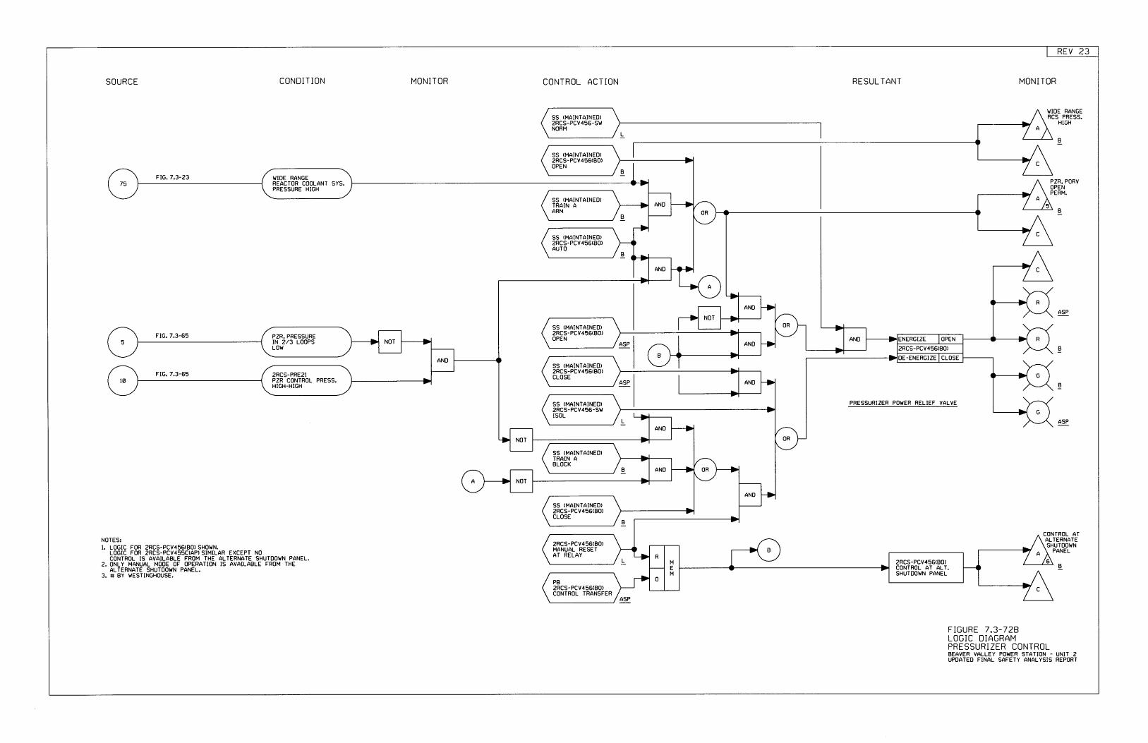
REV Z3
SS (MAINTAINEDIzRCS-PCV456(BO}OPEN
WIDE RANGEREACTOR COOLANT SYS.PRESSURE HIGH
ANI]55 (MAINTATNED}TRAIN AARM
55 (MAINTAINED)2RCS-PCV455(BO)AUTO
ANO
ANO
NOT
ENER6IZE OPEN
SS (},IAINTAINEI])2HC5-PEV456(80)OPEN ANONOT
2RCS-PCV456tE0lAND
PZR. PRESSUREIN 2/3 LOOPSL0I{
DE.ENERGIZE CLOSEANO5S (MAINTAINEO)zRCS-PCV456(BOrCLOSE
ANt}2ECS-PRE2IPZR CONTROL PRESS.HIGH-HIGH
SS (MAINTAINEOI2RC5-PCV456-SUISOL
AND
NOT
S5 II,IAINTAINEDITRAIN ABLOCK
AND
NOT
ANT]
5S (MAINTAINEB)zRCS-PCV456(80)CLOSE
zRCS-PCV456(BOIMANUAL RESETAT RELAY R
2RCS-PCV456(B0rCONTROL AT ALT.SHUTDOWN PANEL
MEM
0PB2RC5-PCV455(80)CONTROL IRANSFER
SS (MAINTAINEI]IzRCS-PCV456-SWNORH
SOURCE CONDITION MONITOR CONTROL ACTION RESULTANT MONITOR
WIOE RANGERCS PRESS.
HIGH
LE.
FIG. 7.3-23B
PZR, PORVOPENPERI'I.
BB
ASP
FIG. 7.3-65
E
FIE. 7.3-55
E
PFESSURIZER POWER RELIEF VALVE
A5P
B
B
NOTES:l. LoGIC FoR 2RCS-PCV456(B0I SHoWN.
LOGIC FOR zRES-PCV4ssC(API SIMILAR EXCEFT NOCONTROL IS AVAILABLE FROM THE ALTERNATE SHUTOOWN PANEL.
2. ONLY MANUAL MOOE OF OPERATION IS AVAILABLE FROM THEALTERNATE SHUTDOWN PANEL.
3. IT BY WESTINGHOUSE.
CONTHOL ATALTERNATESHUTU0tIN
PANEL
L.B
ASP
FIGURE 7.3-7ZBLOGIC DiAGRAMPRESSURIZER CONTROLBEAVEH VALLEY POWER STATION - UNIT 2UPOATEO FINAL SAFETY ANALYSIS REPORT
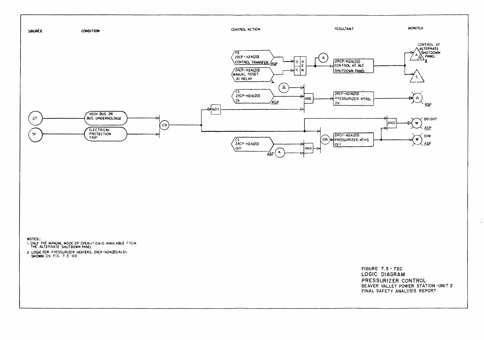
sruRiE CONDITION
480V BUS 2N BUS UNOERVOLTAGE
ELECTRlCAL PROTECTION TRIP
NOTES: I. ONLY THE MANUAL MODE OF OPER,J,TION IS AVAILABlE •ROM
THE ALTERNATE SHUTDOWN PANEL 2 LOGIC FOR PRFSSURIZER HEATERS 2RCP-H2A{ZO)ALS(J
SHOWN ON Fl G. 7. 3- 69
CONTROL ACTION
PB 2RCP- H2A{ZO) CONTROL TRANSF
2RCP- H2A(ZO) MANUAL RESET
AT RElAY
cs 2 RC P -H2A(ZO) ON
cs 2 RC P-H2 A(ZO) OFF
RESULTANT 1.40NITOk
CONTROL AT ALTERNATE SHUTDOWN A PANEL 6
2RCP-H2A(ZO) a. CONTROL AT ALl SHUTDOWN PAN L
L~
2RCP-H2 0 i
PRESSURIZER HTRS. ON AS!'
BRIGHT
ASP
2RCP-H2A{ZO) DIM PRESSURIZER HlRS OFF ~
FIGURE 7.3- 72C 1LOGIC DIAGRAM PRESSURIZER CONTROL BEAVER VALLEY POWER STATION -UNIT 2 FINAL SAFETY ANALYSIS REPORT
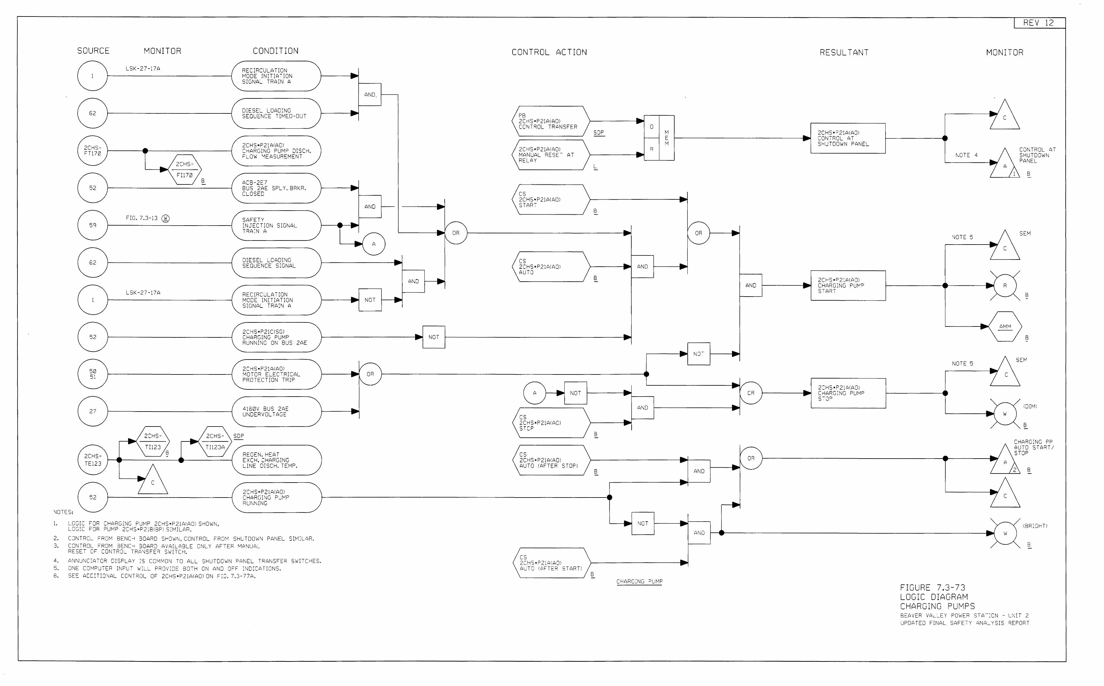
SOURCE MONITOR CONDITION
LSK-27-17A RECIRCULATION 1 MODE INITIATION
SIGNAL TRA;N A
62 DIESEL LOADING SEQUENCE TI~ED-OUT
2CHS•P21AIAOl 2CHS- CHARGING PUMP DISCH. FT170 eLOW MEASUREMENT _/2cHs-
""'\FI170 B AC3-2E7
52 BUS 2AE SPL Y. BRKR. CLOSEC
FIG. 7.3-13 @ SAFETY 59 INJECTION SIGNAL
TRAIN A
62 DIESEL LOADING SEQUENCE s;GNAL
LSK-27-17A RECIRCULATION 1 MODE INITIATION
SIGNAL TRAIN A
2CHS•P21CISGI 52 CHARGING PUMP
RUNNING ON BUS 2AE
2CHS•P21AIAQ) 50 MOTCR ELECTRICAL 5~ PROTECTION TRIP
27 4160V BUS 2AE UNDERVOLTAGE
/2::Hs-\ - /2CHS-\ SOP
Tll23 TI123A B
c
NOTES:
1. ~-CGIC FOR CHARGING PUMP 2CHS•P21AIAOI SHOWN, L.CGIC FOR PUMP 2CHS•P21B\BPI SIMILAR.
REGEN. HEAT EXCH. CHARGING LINE DISCH. TEMP.
2CHS•P21AIAOI CHARGING PUMP RUNN1NG
2. CONTROL FROM BENCH BOARD SHCWN, CCNTROL FROM SHUTDCWN PANEL SIMILAR. 3. CONTROL FROM BENCH BOARD AVAILABLE ONLY AFTER MANUAL
RESET OF CONTROL TRANSFER SWITCH.
4. ANNU~CIATOR DISPLAY IS COMIVON TO ALL. SHUTDO'..JN PANEL TRANSFER SWITCHES. 5. ONE C0"1PUT~R INPL T WIL~ PROVIO~ 80-H ON AND OFF INDICATICNS. 6. SEE ADDITIONAL CONTROL CF 2CHS•P21AIACI ON ciG. 7.3-77A.
• AND
•
__., .....
ANC
-.----. -- A -•
AND
• NOT .. -_L ... -
1/-_... OR ..
'"-.__
_... .....
... -1/ • OR 1"-.
•
NOT
CONTROL ACTION
PB 2CHS•P21AIAQ) CCNTROL TRANSFER
2CHS•P21AIAQ) MANUAL RESET RELAY
cs 2CHS•P21AIAQ) START
cs 2CHS•P2;AIAOl AUTO
A }----+
::s 2CHS•P21AIAOl STOP
cs 2CHS•P21AIAOl
AT
NOT
AUTO !AFTER STOPI
cs 2CHS•P21AIAOI AUTO !f:>FTER START!
• 0 SOP M .. - E ...
M R •
L -
• B - -• OR • 1'-._
• AND • B -
AND •
... - .. .. ..... NOT ....
l .. 1/ ..... • OR • 1"-._ AND -.....
_., ..... B -
B AND
NCT
AND
B CHARGING =>LMP
RESULTANT
2CHS•P21AIAOI CONTROL AT SHUTDOWN PANEL
2Ci-"S•P21AIAOl CHARGING PU~P START
2CHS•P21f\IAOl CHARGING PUMP s-:-oP
NOTE 4
NCTE 5
NOTE 5
~
FIGURE 7.3-73 LOGIC DIAGRAM CHARGING PUMPS
REV 12
MONITOR
c
__., z A
__.,
7 c
-• R
__., AMM ..
_.
7 c
..; w
c
c s p
1
s
J
SE
ONTWJL A7 HUTDOWN ANEL
B
EM
B
B
I DIM I
B
CHARGING PP AUTO START/ STOP
B
IBR:GHI
B
BEAVER VALLEY POWE~ STAT:ON - UNIT 2 UPDATED FINAL SAFETY ANA~vSIS REPORT
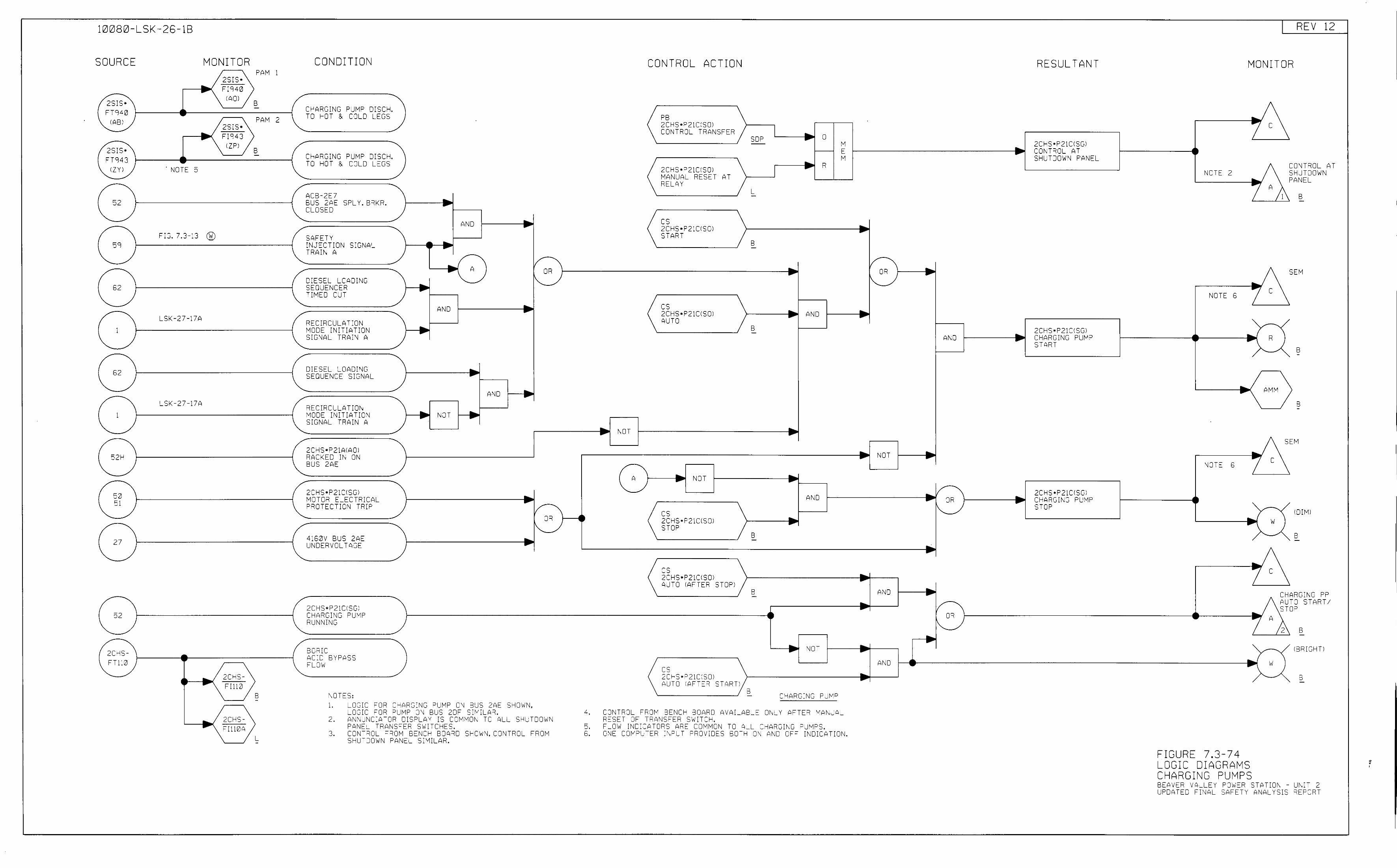
10080-LSK -26-18
SOURCE
2SIS• FT940
lAB I
2SIS• FT943
IZY I
52
59
52
1
52
1
52-I
<:0 51
27
52
2C-IS-FTLO
MONITOR
... -. NOTE 5
F:G. 7.3-13 ®
LSK-27-17A
LSK-27-17A
2SIS• FI940
IAOl
2SIS• FIC:43
IZPI
2CHS-FI111Z
2CI-'S--Ill0A
PAM 1
B
PAM 2
B
B
L
CONDITION
C-IARGING PUMP DISC-I. TO HOT & COLD LEGS
C-lllRGING PUMP DISC-I. TO HOT & COLD LEGS
ACB-2E7 BUS 2AE SPL Y. BRK=i.
__., --CLOSED .. AND .. SAFETY ~NJECTION SIGNA'- ..---. TRAIN A
I/ -- A OR -CIESO:L LOADING ~
- I" SEQUENCER TIMED OUT
AND • RECIRCULATION MODE INITIATION ~ SIGNAL TRAIN A
DIESEL LOilOING • SEQUENCE SIGNAL .. AND .. RECIRCLLATiON __. .. MODE INITIATION NOT SIGNAL TRAIN A -. .. 2CHS•P21AIAOI RACKED IN ON BUS 2AE
2CHS•P21CISGI MOTO=i ELECTRICAL • PRJ-;-ECTION TRIP
4160V BUS 2AE UNDERVOLTAGE
2CHS•P21CISG: CHARGI\JG ::>UMP RUNNING
BORIC ACID BYPASS FLOW
NOTES:
-.....
1. LOGIC =-oR CHARGING PUMP CN BUS 2AE SHO\v\J, LOGIC =-oR PUMP 0~ BUS 2DF SIM;LAR.
/-OR
"-
2. A\JhUNCIPTOR DISPLAY IS COM~ON TO ALL SHUTCO\VN PANEL TRANSFO:R SWITCHES.
3. CJNTRCL FROM BENCH BOARD S~OWN, CONTRCL FROM S-IUTJOWN PANEL SIMILAR.
4.
5. 5.
• NOT
-A
-
CONTROL ACTION
PB 2CHS•P21CISOI CONTROL TRANSFER
2CHS•P21CISOI MANUAL RESET RELAY
cs 2CHS•P21CISOI START
cs 2CHS•P21CISOI AUTO
• NOT
cs 2C-iS•P21CISO! STOP
cs 2CHS•P21CISOI
AT
AUTO !AFTER STOP!
cs 2CHS•P21C!SOI AUTO !AFTER STARTI
B
I .. 0 SOP ~ -E f."
J .. R
L -
B -
• • AND
B -
__., ----
AND
• -B -
B
NOT
CHARGING PUMP
CONTROL FROM BENCI-' BCARD AVAILAB_E O~LY AFTER MANUAL RESET OF TRANSFER SWITCH. FLOW I\JDICATCRS ARE COMMCN TO ALL CHARGING PUMPS. CNE COMP'TER :~~PUT "ROVIOES BOTH ON llND OFF INDICATICN.
• 1/
OR I"._
.. ....
• NOT
AND
Al\0
RESULTANT
2CHS•P21CISGI .. CONT:::OL AT S-IUTJOWN PANEL
•
2CHS•P21CISGI AND • CHARGING PUMP
START
... /- 2CHS•P21CISGI - • .... OR CHARGING PUMP
" STOP
•
OR
REV 12
MONITOR
• NOTE 2
• NOTE 5 z
-.(
NOTE 6
_.. -
FIGURE 7.3-74 LOGIC DIAGRAMS CHARGING PUMPS
c
A
c
R
AM)-1
c
w
c
1
s
c s p
ONFWL AT HUTOOWN ANEL
B
SEM
B
s
EM
IDIMI
s
CHARG:"JG PP AUTO START/ STOP
s
IBRIGHTJ
B
BEAVER VALLEY POWO:R STATIOl\ - JNI- 2 LPOATEO F:NAL SA=-ETY ANALYSIS REPORT
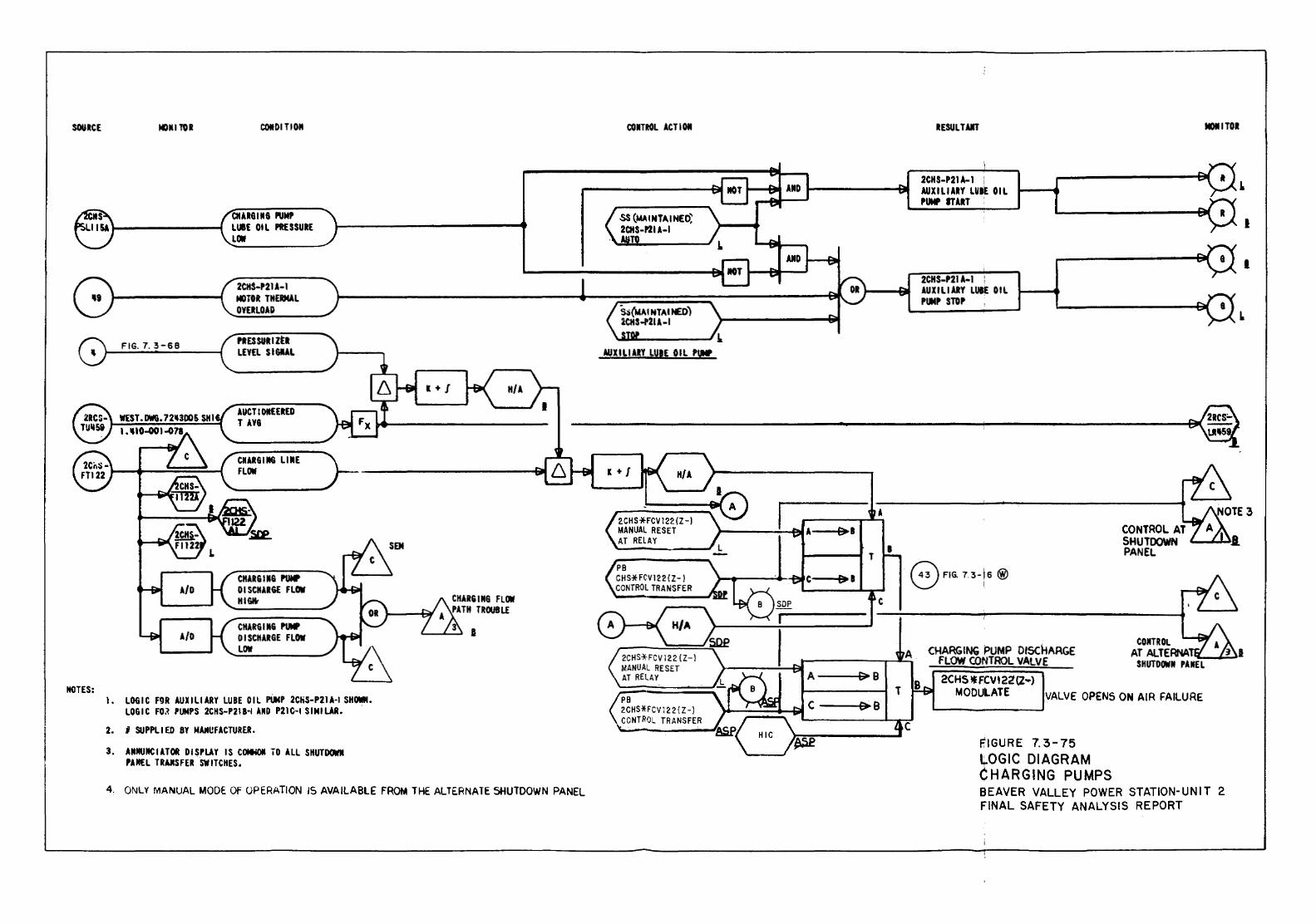
SOURCE
IICITES:
IGMilOII
FIG. 7. 3-68
COitDI TIGM
QIAII6UIG PUMP LUBE OIL PRESSURE LOW
2CH$-P21A-l MOTOR THERMAL OYEIILOAD
PRESSURIZER LEVEL S I GIAL
1+/
CONTROL ACT I Ofl
AUXILIARY LUIE OIL PU!!
RESULT All
2CU-P21A-I I AUXILIARY LUBE OIL PU!! ITAIIT '
2CHS-P21A·I AUXILIARY LUIE OIL PUMP STOP
MOliTOR
AUCTIOIIEEREO T .lYG --------------------------------------------------------~---------------------------~
CH.liiGIMG P'UNP OISCH.liiGE FLOW HI &It
CH.liiGIIIG PUMP DISCHARGE FLOW LOW
I • LOGIC F911 .lUX I L1 AllY LUBE 0 I L PiMP 2Cii$-P21A-t SHCMI. LOGIC FO~ PUMPS 2CHS-P218·t AIIO P2lt-t SIMILAR. .
2. I SUPPLIED BY M~UFACTUREII.
3. AIIMUitCIATOI DI$PLAY IS COIN)II 10 All SHUTDOWI PAJIEL TRAJCS FEll SWITCHES,
4. ONLY MANUAL MODE. Of OPERATION 15 AVAILABLE FROM THE ALTE.RNATE SHUTDOWN PANEL
I +I
2CHS*FCV122 (Z-) MANUAL RESET AT RELAY
PB CHSHCV122 ( Z-) CONTROL TRANSFER
A
(>I
T
~I
c
A---t:;. ~B
[)B
I
T
CONTROL AT SHUTDOWN PANEL 8 FIG. 7.3-16@
A
8
c
CHARGING PUMP OISdiARGE FLOW CONTROL VALVE
2CHS *FCVI22(Z•) MODULATE VALVE OPENS ON AIR FAILURE
RIGURE 7. 3-75 lOGIC DIAGRAM CHARGING PUMPS BEAVER VALLEY POWER STATION-UNIT 2 FINAL SAFETY ANALYSIS REPORT
I.
I
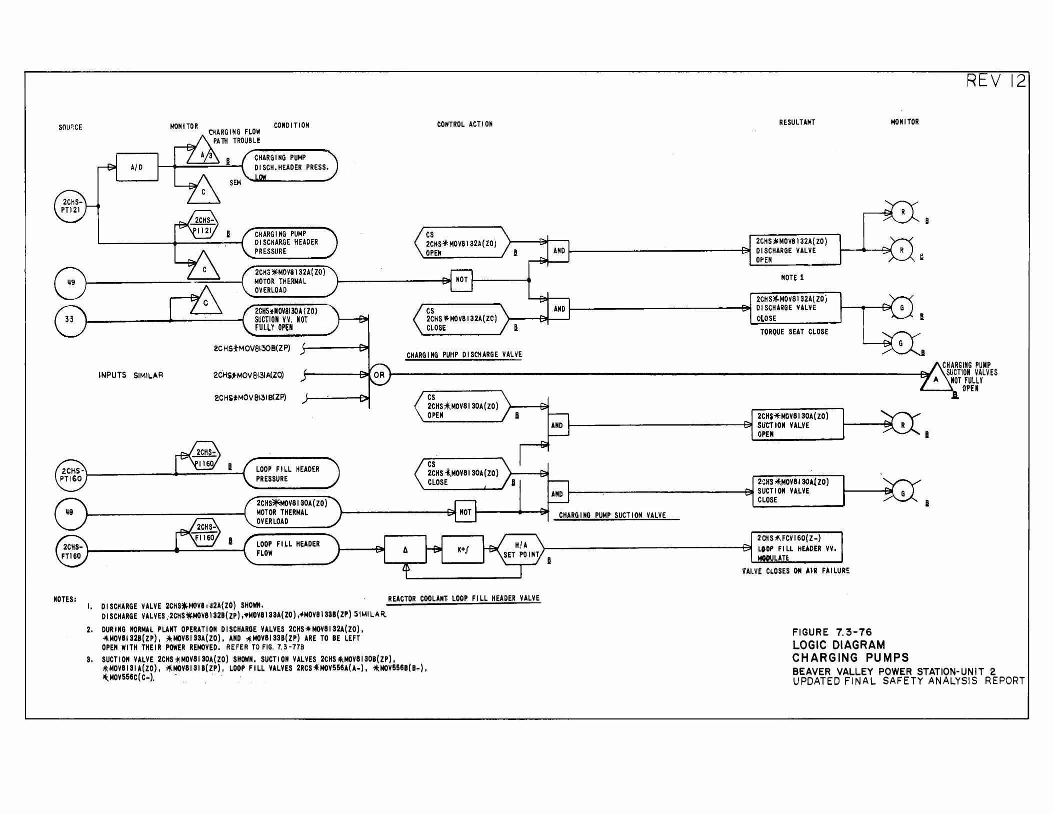
sour;cr
8
NOTES:
AID
INPUTS SIMILAR
MONITOR CHARGING FLOW CONDITION
PA lll TROUBLE
CHARGING PUMP DISCH.HEADER PRESS.
CHARGING PUMP DISCHARGE HEADER PRESSURE
2CHS~MOV8132A(ZO) MOTOR THERMAL OVERLOAD
2CHSfNOV8130A ( ZO) SUCTION VV. NOT fULLY OPEN
2CHSfMOV8130B(ZP)
2CHS~MOV 8131 PI.,ZO)
2CH&tMOV8131B{ZP)
LOOP FILL HEADER PRESSURE
2CHS~OV8130A(ZO) MOTOR THERMAL OVERLOAD
LOOP FILL HEADER FLOW
I. DISCHARGE VALVE 2CHS~MOV8•a2A{ZO) SHOWN.
CONTROL ACTION
cs 2CHS.j MOV8l32A (ZO) OPEt4
NOT
cs 2CHS*MOV8132A(ZC) CLOSE
CHARGING PUt1P DISCHARGE VALVE
A
cs 2CHS~MOV8130A(ZO) OPEN
cs 2CHS {MOV8130A(ZO) CLOSE
K+J
· REACTOR COOLANT LOOP FILL HEADER VALVE
DISCHARGE VALVES ;2CHS~MOV8l32B( ZP) ,•MOV8133A( ZO) ,.fMOV8133B(ZP) SIMILAR.
2. DURING NORMAL PLANT OPERATION DISCHARGE VALVES 2CHS~MOV8132A(ZO), -*MOV8132B(ZP), :*MOV8133A{ZO), AND ~t.IOV8133B(ZP) ARE TO BE LEFT OPEN WITH THEIR POWER REMOVED. REFER TO FIG. 7.3-778
3. SUCTION VALVE 2CHS*t.IOV8130A{ZO) SHOWN. SUCTION VALVES 2CHS*-MOV8130B(ZP), *MOV8131A(ZO), 71\t.IOV8131B{ZP), LOOP FILL VALVES 2RCS .. MOV556A(A-), *t.tQV556B(B-), *:,MOV556C( C-). • . ·
RESULTANT MONITOR
2CHS~MOV8l32A( ZO)
--0~ AND DISCHARGE VALVE OPEN
NOTE 1
2CHS~M0¥8132A(ZOj AND DISCHARGE VALVE
ClOSE TORQUE SEAT CLOSE
2CH$~MOV8130A(ZO) AND SUCTION VAL.YE
OPEN
2·:H'S *.MOV8130A!ZO) 1-----:~------------t3Jt SUCTION VALVE AND ·
CLOSE
CHARGING PUMP SUCTION VALVE
2CHS~FCVI60{Z-)
~----------------t:J~ LOOP FILl HEADER VV. MODULATE.
VALV£ CLOSES Cf4 .UR FAILURE
FIGURE 7. 3-76 LOGIC DIAGRAM CHARGING PUMPS
I
REV 12
B
CHARGING PUMP SUCTION VALVES
NOT FULLY OPEN
I
I
BEAVER VALLEY POWER STATION-UNIT 2 UPDATED FINAL SAFETY ANALYSIS REPORT
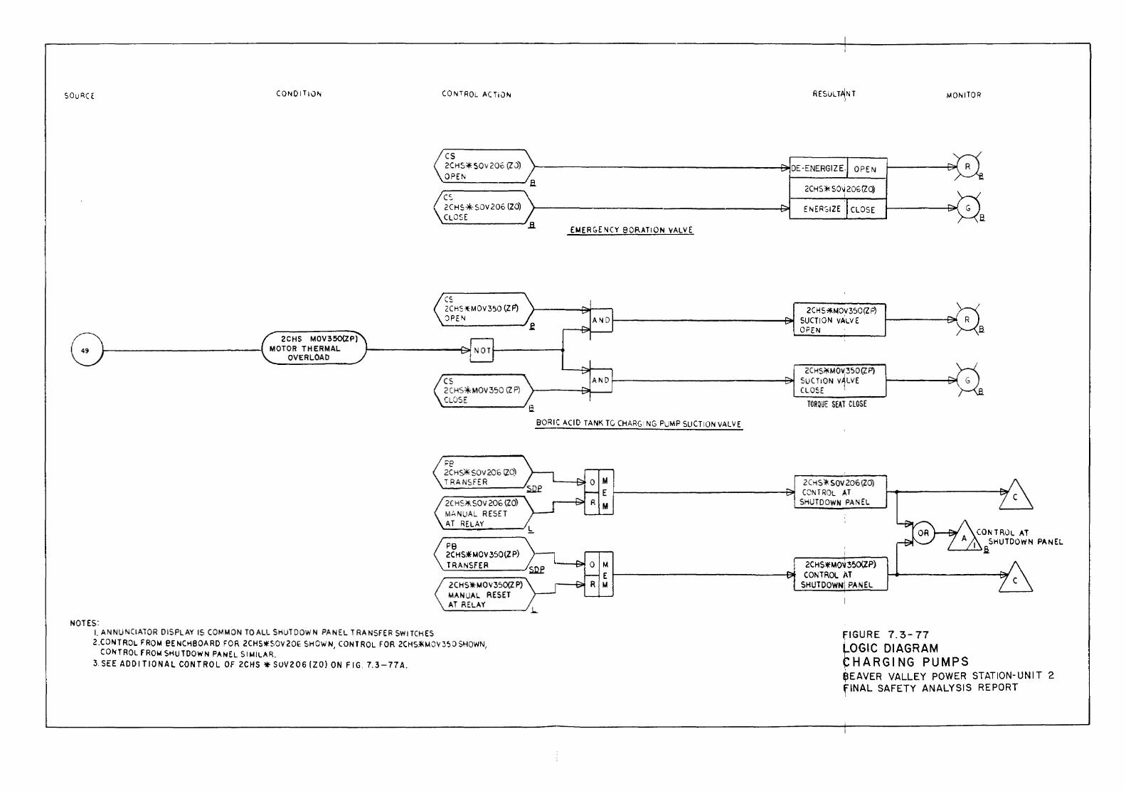
SOuRCE CONOITiuN CONTROL ACTiON
cs >--------------------~DE-ENERGIZE. OPEN 2CHS*SOv206 (ZJ)
OPE !'II ~~----~a
MONITOR
2CHS * S 0~ 20G (l 0) '
ENE RSI ZE CLOSE (~~H s*sov zo.s (ZO) \>----------------------t~ CLOSE ~ ~---~---~ ~---------.a
2CHS MOV350{ZP) MOTOR THERMAL
OVERLOAD
rc. '-~
2CH9fMOV 350 (Z F') :)PEN
cs 2CH9F·MOV350 {ZP) CU:JSE
Fe 2CHS*SOV206 [20) TRANSFER
2C HS*- SOV 206 (ZO) MANUAL RESET AT RELAY ~~:::.:;;.,;.;..,._ __ -..~l:.
PB 2C HS* MDV 350 {Z P) TRANSFER
2CHS*MOV350{Z P) MANUAL RESET
EMERGENCY 80RATION VALVE
BORIC ACID TANK TC CHAR(,• NG PUMP SUCTION VALVE
M E M
2CHS?ii.MOV350(Z P) SUCTION VALVE OPEN
2C HS>!<MO~ 350 (Z P) SUCTION V1LVE CLOSE '
TOROUE SE~T CLOSE
2CHS* SOV 206{20) CONTROL ,.f,T
SHUTDOWN PANEL
M 2CHS*MOV350(ZP) E 1----------------f:~ CONTROL AT M SHUTDOWN;PANEL
CONTF,0L AT I SHUTDOWN PANEL
L.-.....L.!-l.a
AT RELAY ~---::..:;:_ ___ .._) ~
NOTES: L ANNUNCIATOR DISPLAY IS COMMON TO ALL SHUTDOWN PANEL TRANSFER SWITCHES 2.CONTROL FROM eE NCHBOARD FOR 2CHS*SOV 20E SHOWN, CONTROL FOR 2CHS*-MJV350 SHOWN,
CON TAOL fROM SHU TOOW N PANEL SIMILAR. 3. SEE ADD IT 10 NAL CONTROL OF 2CHS * SUV2 06 (ZO} ON FIG. 7.3-77 A.
fiGURE 7.3-77 ~OGIC DIAGRAM CHARGING PUMPS ~EAVER VALLEY POWER STATION-UNIT 2 fiNAL SAFETY ANALYSIS REPORT
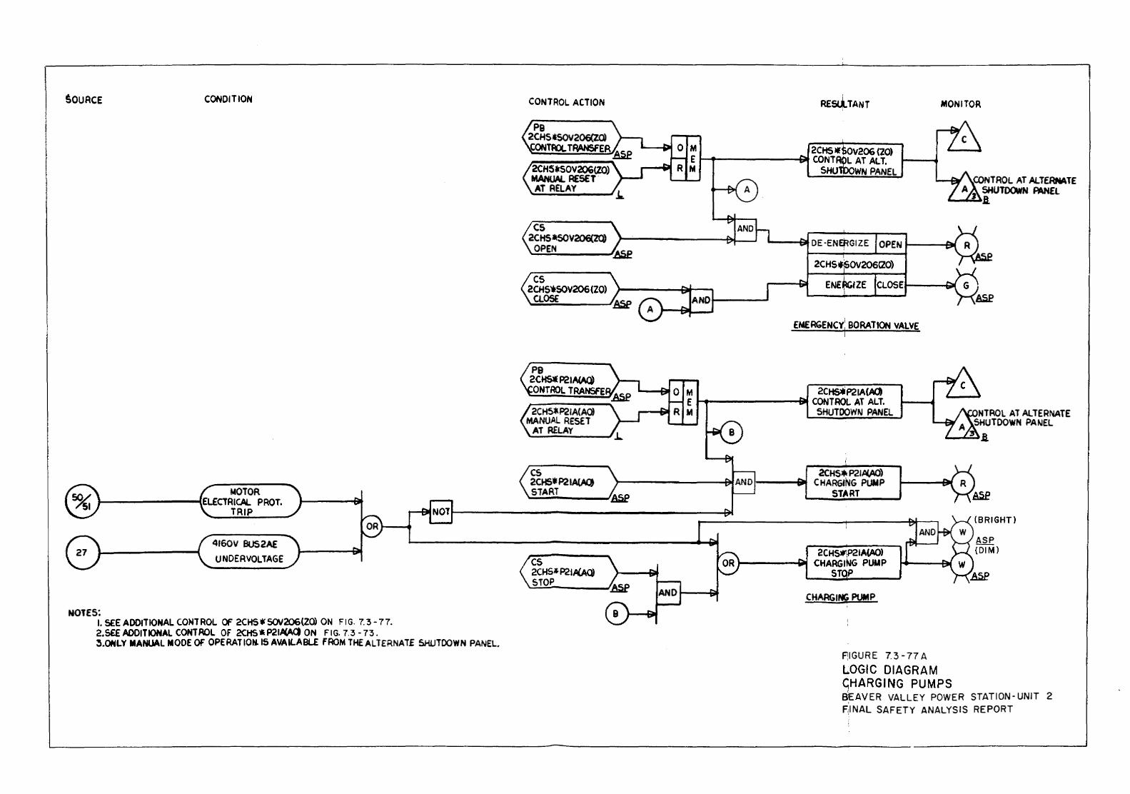
$OURCE CONDITION
MOTOR ,__-------IELECTRICAL PROT.
NOTES:
TRIP
4160V BUS2AE UNDER VOLTAGE
I. SEE A DOlT IONAL CONTROL Of 2CHS * SOV206(ZO) ON FIG. 7. 3 - 7 7. 2. S£E AODIT tONAL COHT ROL Of 2CHS * P21.4(AQ ON FIG. 7. 3 - 73 . S.ONLY MANUAL MODE OF OPE RAT ION. IS AVA K-ABLE FROM THE ALTERNATE SHUTOOWN PANEL.
CONTROL ACTION
2CHS*SOV206(Z()} MANUAL RESET. AT RELAY
2CH5*P21A(AO) MANUAL RESET
AT R£LAY
cs 2CHSt P2lA(A(J START
cs 2CHS~l P21/liAQ) STOP
RE&i.TANT MONITOR
2CHSlfSoV206 {20) 1--4~o--------...j~ CONTROL AT ALT.
SHUlboWN PANEL
EMERGENCY: BORATION VALVE I
2C~P21A(AQ '-------a! CONTROL AT ALT.
SHUTDOWN PANEL
2CHS*- P21.al.AO) 1----1~ CHARGING PUMP
START
2CHS.-!P21A(AO) "'---~~ CHARGING PUUP s p
CHARGING PUMP
f!IGURE 7.3-77 A
LOGIC DIAGRAM GHARGING PUMPS
(BRIGHT)
ASP (DIM)
BEAVER VALLEY POWER STATION-UNIT 2 F.:INAL SAFETY ANALYSIS REPORT
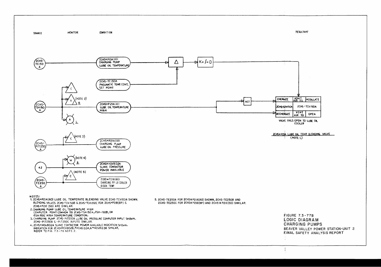
SOURCE MONITOR
ZCHS* P21A (A 0 I CHARbiNG PUMP LUBE OIL TENPERATUR
2CtiS-TC 150A PN[U~TIC TEMP. CONT. \-----------~ SET POINT
2CHSXP 21A (AO I LUBE OIL TEMPE.RATURE J--------------------4 HI'H
NOTES:
(NOTE 4) ~
2CHS~P21A (AO) CHAR(;IN(, PUMP LUBf OIL PRESSURE
2CHSlif HOV8\32A SLAVE CONTACTOR PWER AVAILABLE
2 CHS* P 21A lAOJ CHAR G lNG P P. LO COOLER OISCH. TEMP.
1. 2CHS*P2\A{AO) LUBE OIL TEMPERATE BLENDING VALVE 2CHS·TCVI50A SHOWN. BLENDING VALVES 2CHS-TCV I':>OB ~ 2CHS-TCV I?OC FOR 2CHS~P21B{BP) C. ZCHSw PZIC (SG) ARE SIMILAR.
2.CHA~INfio PUMP LUBE OIL TEMPERATURE HI&H COI-IPUTER POINT COM~IOH TO 2CHS-TSH !~OA,-TSH-1~6 7 0R -TSH !'flOC HIGH TEMPERATURE CONDITION.
3. C HARbl N' PUMP 2CiiS· PIT250A LU I~E OIL PRESSUR[ COMPUTER INPUT SHQ\.JN. 2CHS_; PIT250B t;.- PI T250C IN PUTS SIMILAR.
4. 2CHS!tMO\I8132A SlA'iE (ONT-'CTOR PO\oiER AVAILABLE INDICATION SHQ\.IN. IND!(ATION FOR 2C HS,.MOV8132B,*HOV8133A,&."' MOV813 36 SIMILAR. REFER TO FIG. 7.3-76 NOTE 2. .
5. 2CHS- TE250A FOR 2CHS * P2 J A{AO) SHOWN, 2CHS-T E 2 508 AND 2CHS- TE250C FOR 2CHS* P21B (BP) AND 2CHS * P21C(SG) SIMILAR.
RESULTANT
MODI.JLATE
OPEN
VALVE FAILS OPEN TO LUBE Ol. COOLER
20fS* p~ LUliE OIL TEMP, BLENDING VALVE ! (NOTE ·1)
I
~IGURE 7.3-778 ll.OGIC DIAGRAM CHARGING PUMPS BEAVER VALLEY POWER STATION-UNIT 2 F. IN AL SAFETY ANALYSIS REPORT
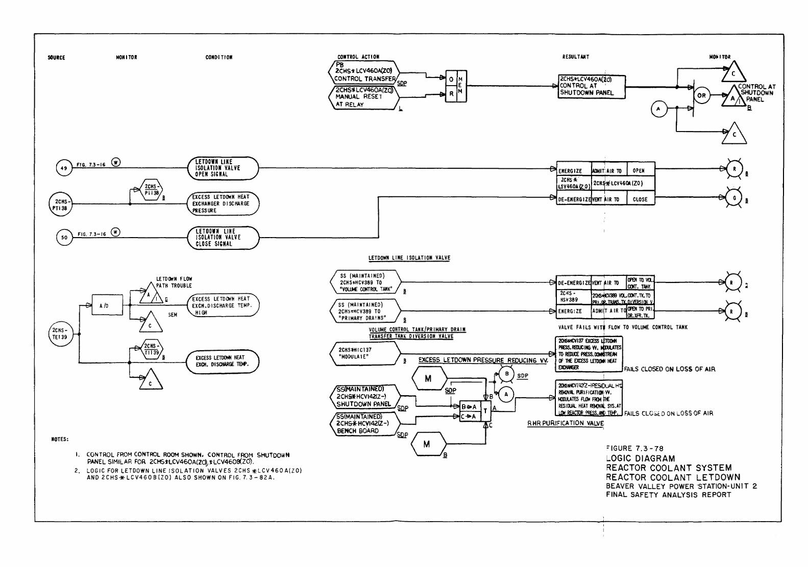
SOURCE
MOTES:
NOM I TOR COMO I TIOII
FIG. 7.3-16 0 LETDOWN LINE ISOLATION VALVE OPEN SIGNAL
EXCESS LETD~M HEAT ~-----+------; EXCHANGER DISCHARGE
FIG. 7.3-16 0
A to
LE TO ()I N FLOW PATH TROUBLE
PIIESS URE
LETDOWN ll N E I SOLATION VAlVE CLOSE SIGNAL
EXCESS LETDOiiN HEAT 1-4~===-:..---4 EXCH. DISCHARGE TEMP.
HIGH
EXCESS LElDOirfl HEAT EXOI. DISCHARG£ IDP.
I. CONTROL fROM CONTROL ROOM SHOWN. CONTROL FROM SHUiOOWN PANEL SIMILAR FOR 2CHStLCV460A(ZO},'f"LCV460~ZO).
2. LOGIC FOR LETDOWN LINE !SOLATION VALVES 2CHS ;HCV460A(ZO) AND 2CHS-;iE-LCV4608(ZO) ALSO SHOWN ON FIG. 7.3-82A.
CONTROL ACTION PB 2CHS-t LCV460A(ZO) CONTROL TRANSFE
2CHS~LCV460A(ZQ MANUAL RESET AT RELAY
LETDOWN LIME ISOLATION VALVE
SS (MAINH.INEO) 2CHSI<HCV389 TO "VOUM CCtiTROl TAHK" !
SS (MAINTAINED) 2CHSorHCV389 TO "PRIMARY ORA! NS" !
VOLUME CONTROL TANK{PRIMARY DRAIN TRANSFER TANK DIVERSION VALVE
RESUL TAIIT
2CHS•LCV460A(ZO) ~--------------~~CONTROLAT '
SHUTDOWN PANEL
J
VALVE FAILS WIT' FLOW TO VOLUME CONTROL TANK
201S1t£Vl'!l EXCESS PRESS.RBU:IMG W,
NOiiiTOR
I
I
2CHSH I C 137 "MODULATE" >-----------------~ lO REim: PIISS."'"""~'""
SS{MAINTAINED 2CH5-i HCV142fl-) BENCH BOARD
OF 1l£ EmS lETtOfl 1£AT EXOWilER FAILS CLOSED ON LOSS OF AIR
ZK)tt£Vltt2(Z -lPESIDuAL H R&DY.tt. A.R I FICATI(II' VY.
,.------E"' ~m FLQrj F!DITIE RES I ru.ll.. IlEA T R&DYAl SYS. AT
l..loi.:IIUII.:::.w.:lu..:li~:II'..IIDP~·.J FAILS CLO::;t.O ON LOSS OF AIR
=IGURE 7.3-78 LOGIC DIAGRAM REACTOR COOLANT SYSTEM REACTOR COOLANT LETDOWN BEAVER VALLEY POWER ·sTATION-UNIT 2 FINAL SAFETY ANALYSIS REPORT
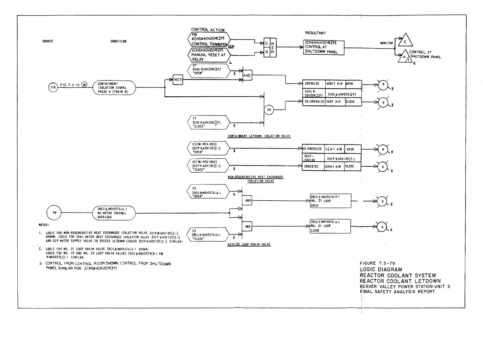
SOURCE
NOTES:
CONDIT! ON
CONTA I iiMENT ISOLATION SIGNAL PHASE A (TRAIN B)
2RCS t MOV557 A I H .NO MOTOR THERKII L OVER LOAD
1. LOGIC FOR NOM-REGENERATIVE HEAT EXCHANGER ISOLATION VALVE 2CGP'*"AOVI30(Z-) SHOWN. LOGIC FOR SEAL WATER HEAT EXCHANGER I SOLA Tl ON VALVE 2CC P f.AOV I 32 ( Z-) AND CC P WATER SUPPLY VALVE TO EXCESS LETDOWN COOLER 2CCP ;ll. AOV I 05 (Z-J SIMILAR.
2. LOGIC FOR NO. 21 LOOP CRAIN VALVE 2RCSA;MOV557A(A-l SHOWN. LOGIC FOR NO. 22 AND NO. 23 LOOP ORA IN VALVES 2RCS ;t;t.IOV 557 B ( 8-l AMO ~ NOV557C ( C-l SIMILAR.
3. CONTROL FROM CONTROL ROOM SHOWN, CONTROL FROM SHUTDOWN PANEL SIMILAR FOR 2CHSt-AOV204(ZP)
CONTROL ACTION PB 2CHSJAOV204(ZP) CONTROL TRANS
. 2CHS *AOV2~/ZPJ "OPEN"
cs
RESULTANT
H 2CHS·tAOV204(ZP) E t------&1 CONTROL AT H SHU TO OWN PAN a
2C HS ~A OV2011{Z P} "CLOSE" "' ~
SS ( !olt6. I NTA I NED) 2CCP ~AOVI30{Z -) "OPEN
SS ( f.IA. I NTA I NED) 2CC P-*' AOV 130(Z -) "CLOSE"
cs 2RCS -f-MOV 5 57 A (A-) "OPEN"
cs 2Rc ~ :* MOV557 A I H "CLOSE"
CONTAINMENT LETDOWN ISOLATION VALVE
NON-REGENERATIVE HEAT EXCHANGER ISOLATION VALVE
\'[NT AIR OPEN
2CC P * AOV 130(Z -)
ADMIT AIR CLOSE
2RC S !f MOV557 A I A-) 1------------~NO. 2t LOOP
OPEN
2RCS '¥ MOVS57A lA-) 1------------t:::'!NO. 21 LOOP
CLOSE
REACTOR LOOP DRAIN VALVE
NON IT OR
8
FIGURE 7. 3-79 ~OGIC DIAGRAM
I
CONTROL AT SHUTDOWN PANEL
8
REACTOR COOLANT SYSTEM REACTOR COOLANT LETDOWN eEAVER VALLEY POWER STATION-UNIT 2 fiiNAL SAFETY ANALYSIS REPORT
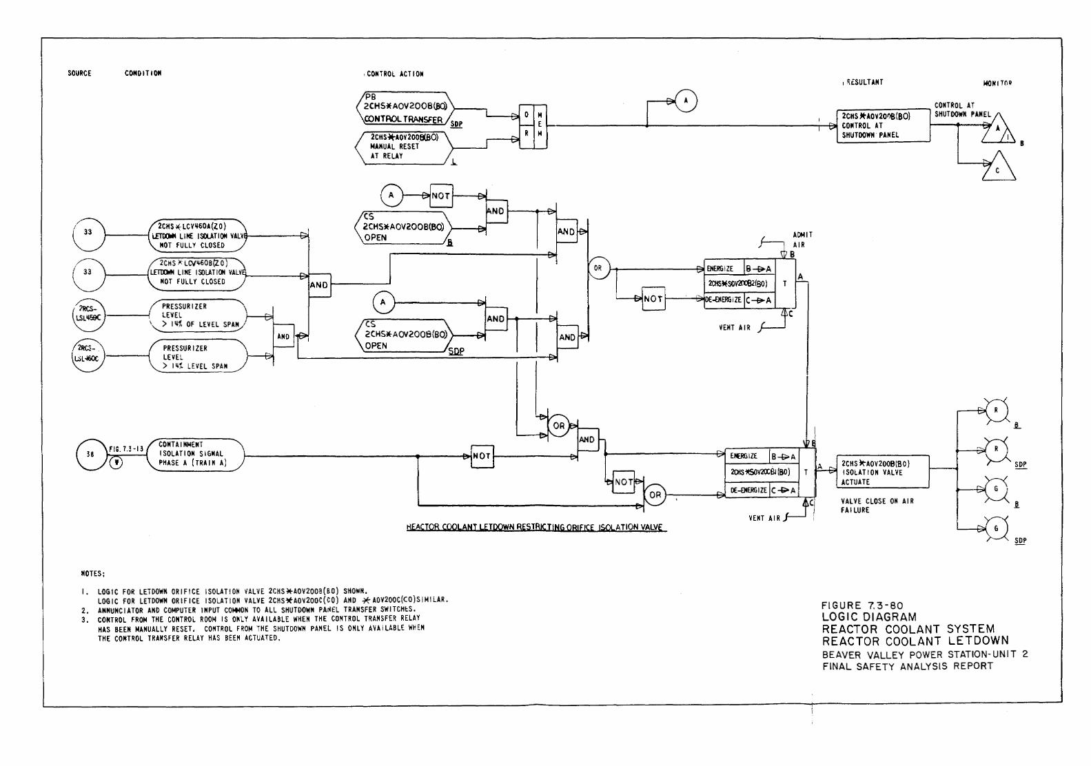
SOURCE CONDIT IOM
@ PRESSURIZER ~ ~-----l LEVEL
I~) 1~% OF LEVEL SPA~
PRESSURIZER LEVEL ) 1~% LEVEL SPAN
COMTAIMMENT ISOLATIOM SIGNAL PHASE A (TRAIN A)
, COHTROL ACTIOM
PB 2CHS*AOY200B(BO) >---....., CONTROL TRANSFER ........___,71
2CHS*AOV 200B(B0) MAMUAL RESET AT RELAY
cs 2CHS!tAOV2008{80) }-~I=!Jij
OPEN A
cs 2 CHSlt A OV2008(80) >----1,_ OPEN
I ~ESULTANT
2CHS .tt-AOV 20fl8 (BO) ._--------+---------------,_,.:::.j COMTROL AT
VENT AIR
ADMIT AIR
B
A
c
SHUTDOWN PANEL
2CHS ~AOV 200BIB 0) I SOLATION VALVE ACTUATE
VALVE CLOSE OM AIR FAILURE
WON ITO~
KEACTQR COQLANT LE!OOWN RESTBIC I!NG OBI FICE ISO!.. A I ION VALVE
MOTES;
I. LOGIC FOR LETDOWN ORIFICE ISOLATION ~ALVE 2CKS~AOV2008(BO) SHOWN. LOGIC FOR LETDOWN ORIFICE I SOLAT I OM VALVE 2CtiS*AOV200C ( C 0) AHD * AOV200C(CO) SIMILAR.
2. AMHUHCIATOR AND COMPUTER INPUT COMMON TO ALL SHUTDOWN PA~£L TRANSFER SWITCHtS. 3. CONTROL FROM THE CONTROL ROOM IS OMLY AVAILABLE WHEN THE CONTROL TRANSFER RELAY
HAS BEEN MANUALLY RESET. CONTROL FROM THE SHUTDOWN PANEL IS ONLY AVAILABLE WHEM THE CONTROL TRANSFER RELAY HAS BEEN ACTUATED.
FIGURE 7.3-80 LOGIC DIAGRAM REACTOR COOLANT SYSTEM REACTOR COOLANT LETDOWN BEAVER VALLEY POWER STATION-UNIT 2 FINAL SAFETY ANALYSIS REPORT
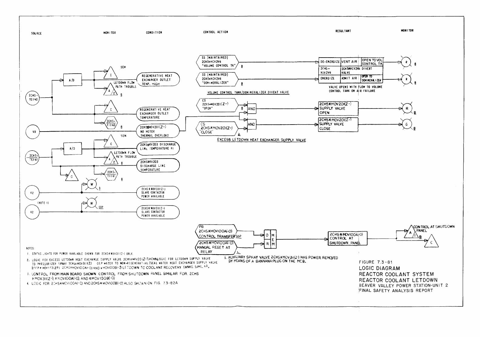
SOO RCE MOK I TOR COKOITION COKTROL ACTIOK RESULT.I.IfT NOifl TOR
SS (MAl NTAINEO)
~ SEM
2CHSI'H02~~ >----------------~DE-ENERGIZE VENT AIR I OPEN TO VOL "VOLUME CO'ITROL TK" ~ ' CONTROL TKI-----+'"i
2CHS- 2CH~CV2~~ 01 VERT
A /0 RE GEitER AT I VE HEAT E~CHA NGER OUTLET
LETDOWN F LCifli , TEMP. HIGH PATH TROUBLE
SS (MAINTAINED) 2CH S~ HCV 2~~ noEMr"ERALIZER"
H:;v2~~ VAL YE
}---------------~ EN ERG I Zf. ADMIT AIR i 094INERAI..IZER ~--~ ~
VALVE OPENS WITH flOW TO VOLUME
VOLUME CONTROL TANK/OEMINERALIZER OIVEkT VALVE CONTROL TANK ON All R FAILURE
REGENERATIVE HEAT EXCHANGER OUTLET TEMPERATURE
2CH S»>O V 20 l (Z-) NO MOTOR THERMAL OVERLOAD
2CH ~tRV 20 3 0 I SCHAR GE ll lit rEMPERA TU RE HI
2CH SJ:RV203 DISCHARGE LINE TEMPERATURE
2CHS HOV 31HZ-) S l ~ VE COM TACT OR POWER AVAILABLE
2CHS* MOV 3111Z-) SLAVE COMTACTOR POtE R AVAILABLE
cs 2CH S.t.tOV20 \( l-) "OP EM"
cs 2CHS*MOV20I{Z0
'cLOS('
2CHSif MOV 20I(.Z -) f-------------t~ SUPPLY VALVE
OPEN
2CHSJ(- MOV 201 (Z-1-------------~SUPPLY VALVE
CLOSE
EXCESS LETDOWN HEAT EXCHANGER SUPPLY VALVE
PB 2 C HS ~H-10VI 0 OA(-0) CONTROL TRA M 2CHS*MJVIOOA:tO)
E ~--------~CONTROL AT ; 2CHS*t..,OVIOO -0 M SHUTDOWN PAN
IIO!ES: MANUAL RESET AT I. STATUS "IGHTS fOR POWER HAILI.BLE SHOWN FOR 2CHSHH311!Z-I ON'.Y. RELAY '---------' 2. LOGIC f" OR EXCESS LETDOWN HEAT EXCHANGE SUPPLY VALVE 2C HSHII'l\'20 !\Z-SHO'!'tN,LOG I C FOR LETDOWN SUP PLY V ALH
TO I'~ <SS URI ZER <; PR.A Y '1CHs.t MOV 31 r:.z.; CCI' WATER TO NON~ E GENERAl 1 V~ /SEAL WATER HEAT DC HANGER SUPPLY vALVE
5. AUXILIARY SPRAY VALVE 2CHS)(M0V.311{Z-) HAS POWER REMQYED BY MEANS OF' A BANNAN A PLUG ON THE MC 8.
'2ff P ~ ~0~ r7 31Z PI 2CHS~HOV IOOAI- 0) A..ND • HCVIOOB{-C) l E ~DOWN TO COOLANT RE COVEH'r TANKS SIH I_:; M, FIGURE 7.3-81
LOGIC DIAGRAM
e.
3. WNTROL FROM MAIN BOARD SHOWN CONTROL FROM SHUTDOWN PANEL SIHILAR FOR 2CHS J- MOV311(Z-). t r--·,oviOOA(-0), AND 't"MOV 1008(-0)
4. LCC:IC FOR 2 :H9cMCV IOO.A.(- C) AND 2CHS* MOV\008(-0) ALSO SH;,'\Ii ~ ON FIG. 7 3-8 2A
REACTOR COOLANT SYSTEM REACTOR COOLANT LETDOWN .BEAVER VALLEY POWER STATION-UNIT 2 !FINAL SAFETY ANALYSIS REPORT
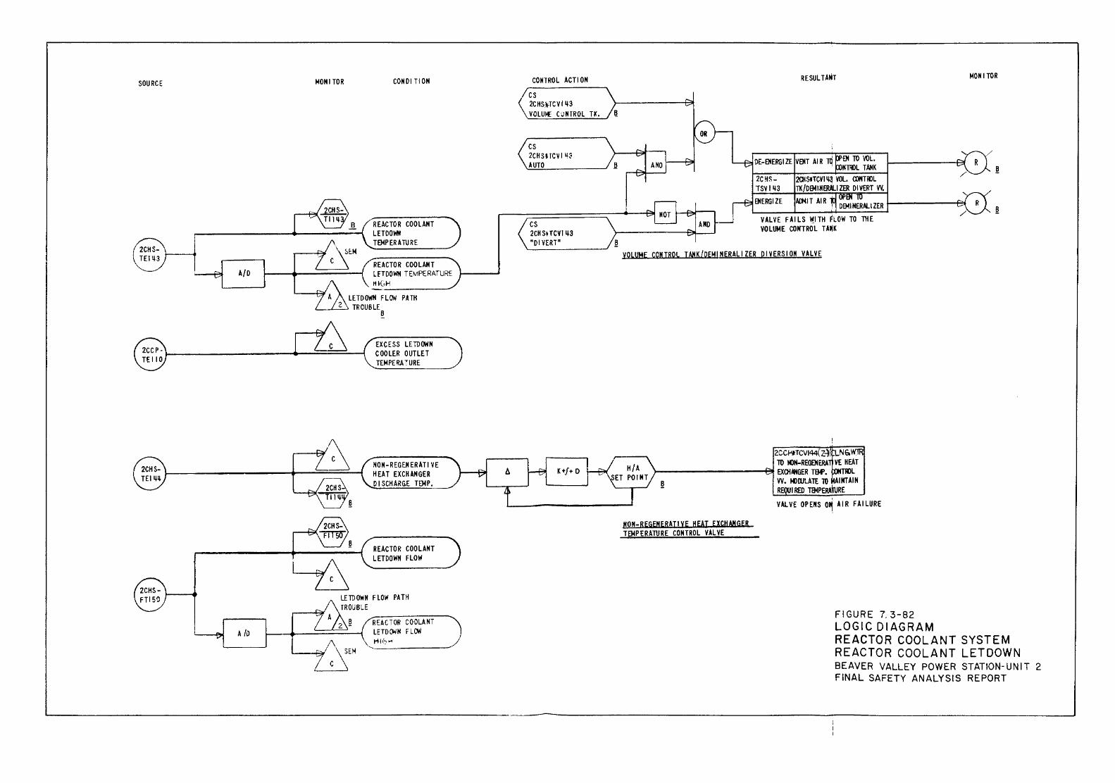
SOURCE
A/0
A {D
MONITOR COMOI TlON
REACTOR COOLANT LETDOWN TEMPERATURE
REACTOR COOLANT LFTOOW!I TEMPERATURE IIIGH ---------
LETDOWN FLOW PATH 2 TROUBLE
8
EXCESS LETDOWN COOLER OUTLET TEMPERA ~URE
NOM-REGENERATIVE HEAT EXCHANGER 0 I SCH ARGE TEMP.
REACTOR COOLANT LETDOWN FLOW
REACTOR COOLANT LETDOoi'N FLcM
CONTROL ACTION
cs 2CIIS;\-TCVI143 VOLUJ.E C'JNTROL TK.
cs 2CKSHCVI k!~ AUTO
cs 2CH Sl TCVI 143 "OIVERTn
K+f+ 0
!l
RESUL TAM!
VEMT AIR 1ti EM TO VOL. OE-ENERGI ZE MOOL TAHK
VALVE FAILS WITH FLOW TO THE VOLUME COKTROL TAMK
MONITOR
~
VOLUME CONTROL TAHK/pEMINERALIZER piVERSIOM VALVE
2CCPHCV144(Z4 LNG. TO !ClH-REGENERA VE IlEA T
}---------~ EXOINIGER TIM'. TtllL
NON-REGENERATivE HEAT EXCHANGER TEMPERATURE CONTROL VALVE
VV. l()llJLATE lO AINTAIN R I RED mtPERAiruRE
VALVE OPENS 0~ AIR FAILURE
FIGURE 7. 3-82 LOGIC DIAGRAM REACTOR COOLANT SYSTEM REACTOR COOLANT LETDOWN BEAVER VALLEY POWER STATION-UNIT 2 FINAL SAFETY ANALYSIS REPORT
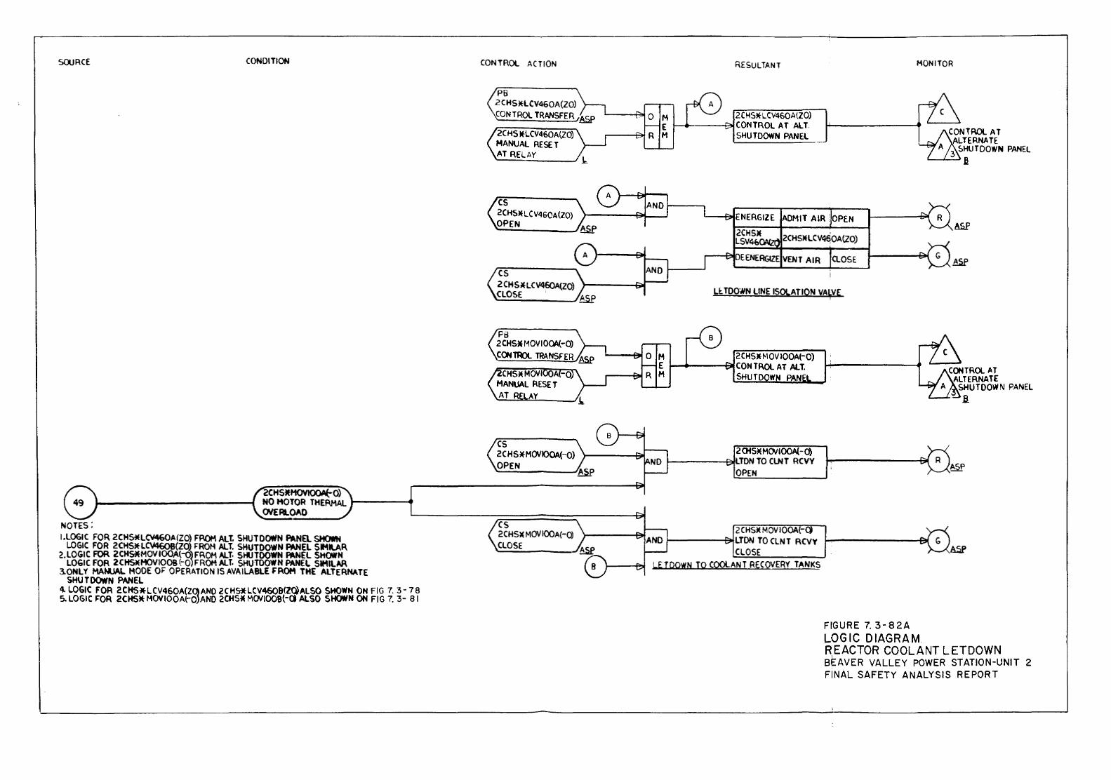
SOURCE
NOTES;
CONDITION
2CHSJfHOVIOOA(-O) NO MOTOR THERMAL l------<t OVERLOAD
!.LOGIC FOR 2CHS*LCV460A(ZO) FROM ALT. SHUTDOWN PANEL SHOWN LOGIC FOR 2CHSJfLC\f460B{ZO) FROM ALT. SHUTDOWN PANEL SIMilAR
2.LOGIC FOR 2CHS*MOVIOOA(-Q)FROM All· 51-l.JTOOWN FNIEL SHOWN LOGIC FOR 2CHS*MOVIOOB (-Q) FROM AlT. SHVTOOWN PANEL SIMILAR
3.0NLY MANUAL MODE OF OPERATION IS AVAILABLE fROM THE AlTERNATE SHUTDOWN PANEL
4. LOGIC FOR 2CHS*LCV460A(ZQANO 2CHS*LCV46QB(Z(jALSO SHOWN ON FIG 7. 3-78 S. LOGIC F'OR 20fSM- HOY IOQA{-Q}ANO 2CHS* MOVlOOB(-ct ALSO SHCWN ON FIG 7. 3- 8 I
CONTROL ACTION
PB 2CHS)(LCV460A(20) CONTROL TRANSFER ASP
2CHS )fLCV41)()A(.ZO) MANUAL RESET
'-A....:..T....:..R:.=.E.=.:lA...:.:.Y __ __j .I._
cs 2CHS)( LC V46CA (ZQ) OPEN
cs 2 CH S* LCV460AlZO) CLOSE ' ~
Fd 2 CHS* MOV I OOA(-0) COII'Tin. TRANSFER ~
cs 2C HS*MOVIOOA(-Q) OPEN ASP
cs 2CHSX MOV IOOA{-0) CLOSE
RESULTANT
2C HS*L CV4GQA tZO) ~._----I~CONTROL AT ALT.
SHUTDOWN PANEL
MONITOR
ADMIT AIR ':OPEN
L~ TDOiVN LINE ISQLATION VA~VE
2 CHS*MCWIOOA( -~ 1-----~:LTON TO CLNT RCVY
OPEN
2 CHS*MOVIOOA -Cj 1-----~LTON TO CLN T RCVY
CLOSE LETDOWN TO CQOLANT RECOVERY TANKS
FIGURE 7. 3-8 2A LOGIC DIAGRAM REACTOR COOLANT LETDOWN BEAVER VALLEY POWER STATION-UNIT 2 FINAL SAFETY ANALYSIS REPORT
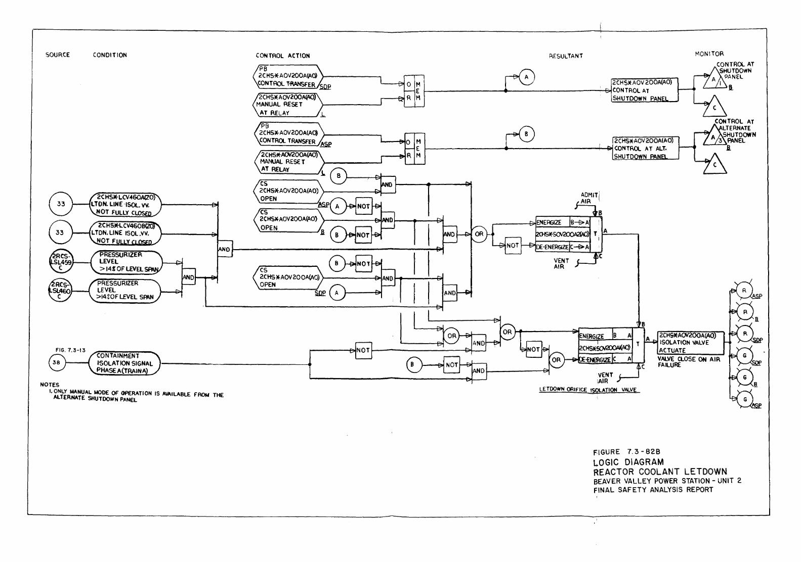
SOURCE
NOTES
CONDITION
PRESSURIZER LEVEL >147.0Fl£VEL SPAN
CONTAINMENT ISOLATION SIGNAL PHASE A(TRAIN' A
1·~~tR':t:TUEAL MODE OF OPERATION IS AVAILABLE FROM THE SHUTDOWN PANEL
CONTROL ACTION
2CHS*ACN200A~ MANUAL RESE T AT RELAY
cs 2CHS*AOV200A(AO) >--------G;;L--l OPEN
cs 2CHS~AOV200A~O)
OPEN
cs 2CHS*AOV200A(AO) r--------sMAN OPEN
R.ESULTANT MONITOR CONTROL AT SHUTDOWN
M 2CHS*AOV200~0 A PANEL
I ll. E ~--------------~~------------------~CONTROLAT M SHUTDOWN PA
2 C HS*AOV 200A(A0 t------------_.------------4~CONTROL AT ALT.
SHU TO
LETDOWN ORIFICE ISOLATION VALVE
8 2CHS*ACN200A(AQ ISOLATION VALVE ACTUATE VALVE CLOSE ON AIR c FAILURE
FIGURE 7. 3-828 L.OGIC DIAGRAM REACTOR COOLANT LETDOWN BEAVER VALLEY POWER STATION- UNIT 2 FINAL SAFETY ANALYSIS REPORT

SOURCE MONITOR
NOTE
CONDITION
NON- REGENERATIVE HEAT EXCHANGER DISC PRESSURE
1. ONLY MANUAL MODE OF OPERATION IS AVAILABLE FROM THE AL lERNA TE SHUTDOWN PANEL
CONTROL ACTION
2CHS* PCV 145 MANUAL RESET AT RELAY
2CHS* PCVI45 MANUAL RESET AT RELAY
MONITOR RESULTANT
2C H5* PCV 145 r-~====~------------------------------~--~CONTROL AT Alt
8
SHUTDOWN PANEL
c VALVE OPENS ON AIR FAILURE
2CHSJI(.PCVI45 ----------------f:.tCONTROl AT
SHUTDOWN PANEL
MONITOR
CONTROL AT ALTERNATE
A SHUTDOWN 3 PANEL
.__..........._~.a
CONTROL AT HUTDOWN
A. PANEL I .a
H/A K + f+D 1-------e,;:: SET POINT
'--,---'.B.
LOW PR.ESSUBf LETDOWN VALVE
FIGURE 7.3 -82C LOGIC DIAGRAM FREACTOR COOLANT LETDOWN SEAVER VALLEY POWER STATION- UNIT 2 FINAL SAFETY ANALYSIS REPORT
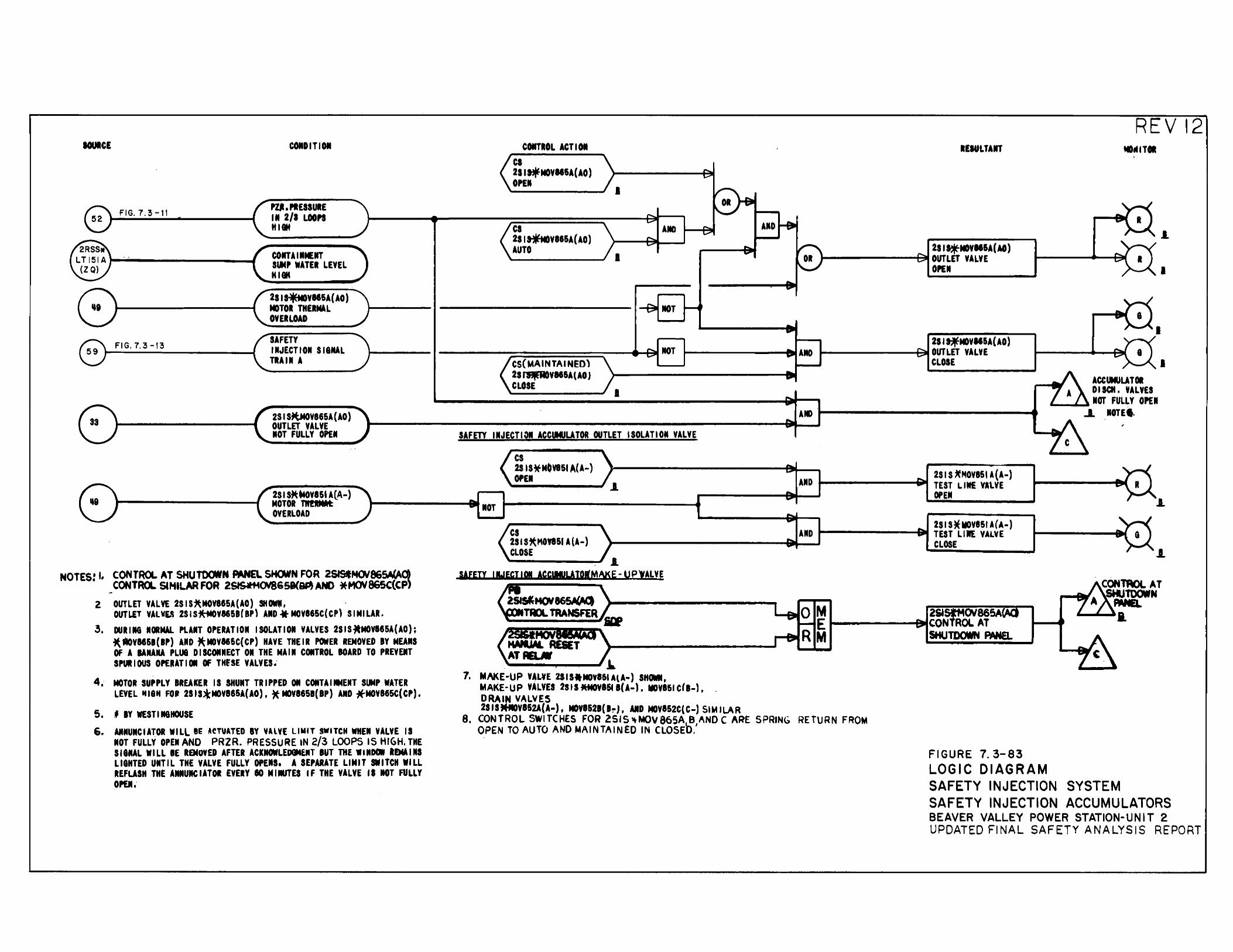
IOUICE
FIG. 7. :3 -II
COIID I Tl 011
PU.PIESSUIE Ill 2/1 LOOPS HI Cit
COITAIIIMEIIT Sli4P WATER LEVEL H 1811
8' (2SI'*-VII5A(AO) ) ~ -~---------4- MOTOR THERMAL 1-· ----
OVERLOAD
FIG.7.:3-1:3 SAFETY IIIJECTIOII SI&IAL TRAil A
2SIS~V865A(AO) OUTLET VALVE IIOT FULLY OPEII
COITIOL ACT I 01 ca 2SI~MOVIISA(AO) OPEII
ca 2SI~VII5A(AO) AUTO
I
lliOT
--------~~==========~----~111~ CS(MAINTAINEO) 2S~VIIIA(AO} CLOSE
I
IEIULTAIIT
2SI'*'MD¥115A(AO) t-------,_.,p~ OUTLET VALVE
OPE Ill
2SI~NOVII5A(AO) 1-------.......jii!IIIIIAIID ~------+~OUTLET VALVE
CLOSE
A~ ~------------------------4 SAFETY IIIJECTIDII ACCUHULATOR OUTLET ISOLATIOII VALVE
cs 28 IS*M0V851 A( A-) OPEl AIID 2SI S ~MOVI5U(A-)
t------......fiiilll TEST LIWE VllVE
REVI2 MDIII Til
.l
I
I
I ACCUMULATOR D I SCII • VALVES
"-----'-...1 IIOT FULLY OPEl ~ IIOTEI.
;
2s1 s~u•ovasl A(A-) MOTOR 111!RMAL ~-------~~ ~------~~~ ~Ell ~ liM ~-----------------~ ~------------~ OVERLOAD
NOTES! I, CONTROL AT SHUTDCJIIN PANEL SHCMN FOR 251StNOI865A(AO) CONTRCL SIMILAR FOR 261Sft4()18&58(~ AND *MOV86SC(CP)
Z OUTLET VALVE 2S IS1tMOV885A(AO) SHM, OUTLET VAL\IL41 2SISit'MOVM58(8Pl AIID * MOV865C(CPl SIMILAR.
3, DURING NORMAL PLAIT OPERATIOII ISOLATION VALVES 2SISJlMOVI65A(AO); ittiOVIISI(IP) AID *MOVI66C(CP) HAVE THEIR POWER REMOVED BY NEAliS OF A IANAIIA PLU8 D I SCONIIECT 011 THE MAl II COIITROL BOARD TO PREYEIIT SMIOUS OPERATIOII OF THfSE VALVEs.·
4.· MOTOR SUPPLY BREAKER IS SHUIIT TRIPPED 011 COITAIIIMENT SUMP WATER LEVEL lti8H FOit 2SIS;t"MOV865A(AO), * MOV8658(8P) AIID *MOV885C(CP).
5. f BY WEST I N&HOUSE
6. ANIIUICIATOR WILl BE ACTUATED BY VAlVE LIMIT SWITCH WHEII VALVE IS IIOT FULLY OPEII AND PRZR. PRESSURE IN 2/3 LOOPS IS HIGH. THE SI&IIAL WILL BE REMOVED AFTER ACKIOWLEDGMERT BUT THE WIIDDI IEMIIMS LIGHTED UIITIL THE VALVE FULLY OPEIIS. A SEPARATE LIMIT SWITCH WILL IEFLASH THE AMIIUICIATOR EVERY 10 MIIIUTES IF THE VALVE II lOT FULLY OPEJI.·
cs 2SI Uh10V851 A(A-) AID t-------~lall TEST LIIE VALVE
21 I S~MOYISI A (A-) CLOSE ~--------------~~~ ~-CL-~-E----------~ .L
.1.
~--.....----' .1.. 7. MAKE-UP VALVE 2SIS.MOYI61 AlA-) SHM,
MAKE-UP VALVES 2StS ftM0¥161 B{A-), MOVI61 C(B-1, DRAIN VALVES 2SIStffiOYI52A(A-), MOYI621(1~J, AID MOVI52C(C-) SIMILAR
8. CONTROL SWITCHES FOR 2SIS~MOV86SA BAND CARE SPRING RETURN FROM OPEN TO AUTO AND MAINTAINED IN CLOSED.'
FIGURE 7. 3-83 LOGIC DIAGRAM SAFETY INJECTION SYSTEM SAFETY INJECTION ACCUMULATORS BEAVER VALLEY POWER STATION-UNIT 2 UPDATED FINAL SAFETY ANALYSIS REPORT
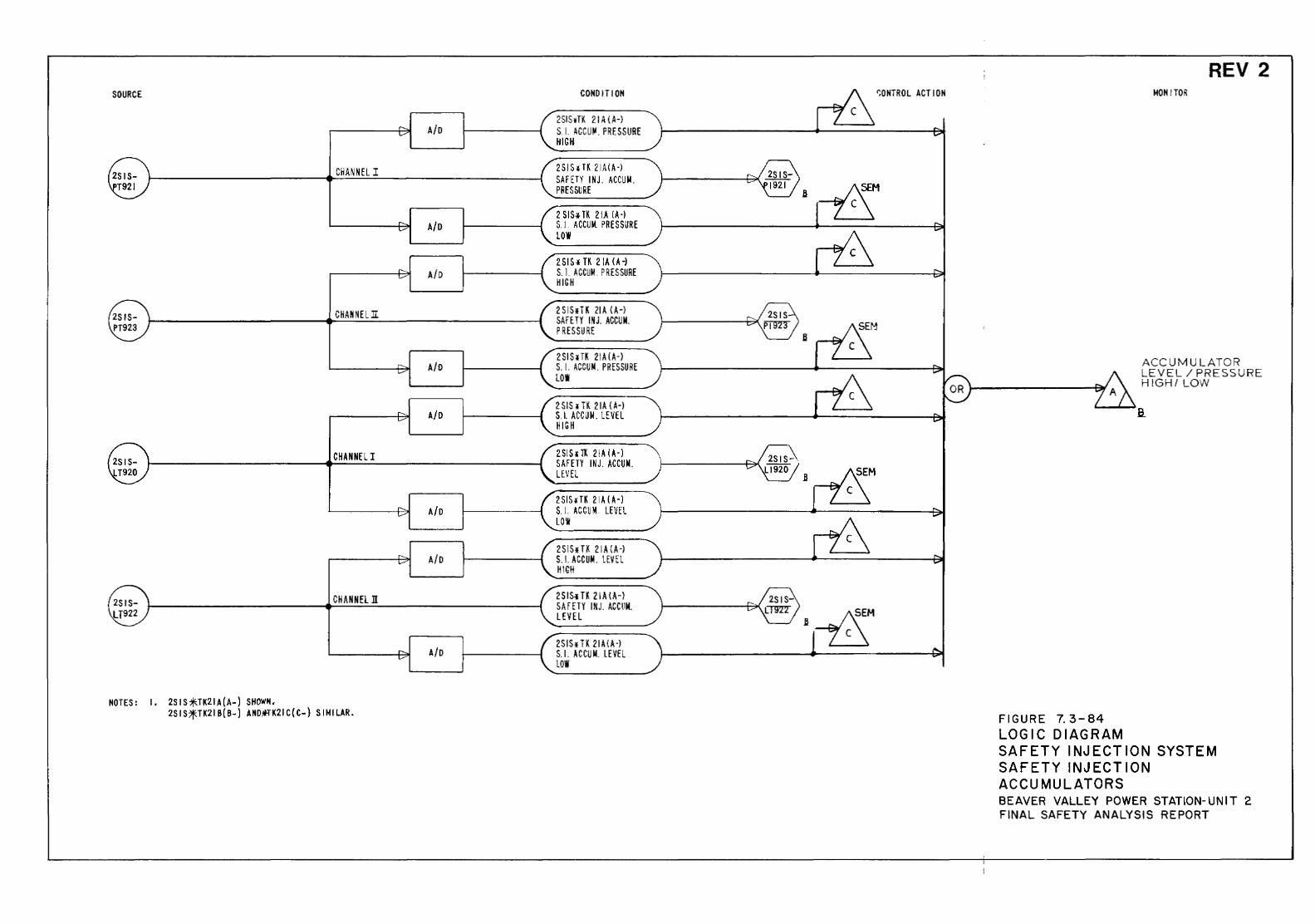
SOURCE
A/0
CHANNEL I
A/0
A/D
CHANNEL 1I
A/0
A/0
CHANNEL I
A/0
A/0
CHANNEl ll
A/0
NOTES: I, 2SIS*TK21A(A-) SHOW'!, 2SIS?fTK21B(B-) ANO~K21C(C-) SIMILAR.
CONDIT ION
2SISvTK 21 A (A-l S I. AGCUI( PRESSURE HIGH-
2SISllK 21A(A-l SAFETY I NJ. ACCU M. PRESSURE
2SISo~TK 21A lA-l S.l. AGCUM. PRESSURE LOW
2SISt TK 21A (A-l S. I. AGCUr.l. PRES SURE HIGH
2SIS*TK 21A (A-l SAFETY IN J. ACCU M. PRESSURE
2SIS¥TK 21A (A-) S. I. ACCUM. PRESSURE LOW
2 SIS~ TK 21A (A-) S.l. ACCUt.l. LEVEL HIGH
2SISITK 21A(A-l SAFETY INJ. ACCUit LEVEL
2SIS4TK 21A(A-l S.l. ACCUM LEVEL L0\11
2SIS4TK 21A(A-l S. LACCUM. LEVEL HIGH
2SIS.-H 21A(A-l SAFElY INJ. ACCllM. LEVEL
2SIS~ H. 21 A( A-) S.l. ACCU M. LEVEL LOW
~ONTROL ACTION
Fl GURE 7. 3-84 LOGIC DIAGRAM
REV 2 MONITOR
ACCUMULATOR LEVEL I PRESSURE HIGH/LOW
SAFETY INJECTION SYSTEM SAFETY INJECT ION ACCUMULATORS BEAVER VALLEY POWER STATION-UNIT 2 FINAL SAFETY ANALYSIS REPORT
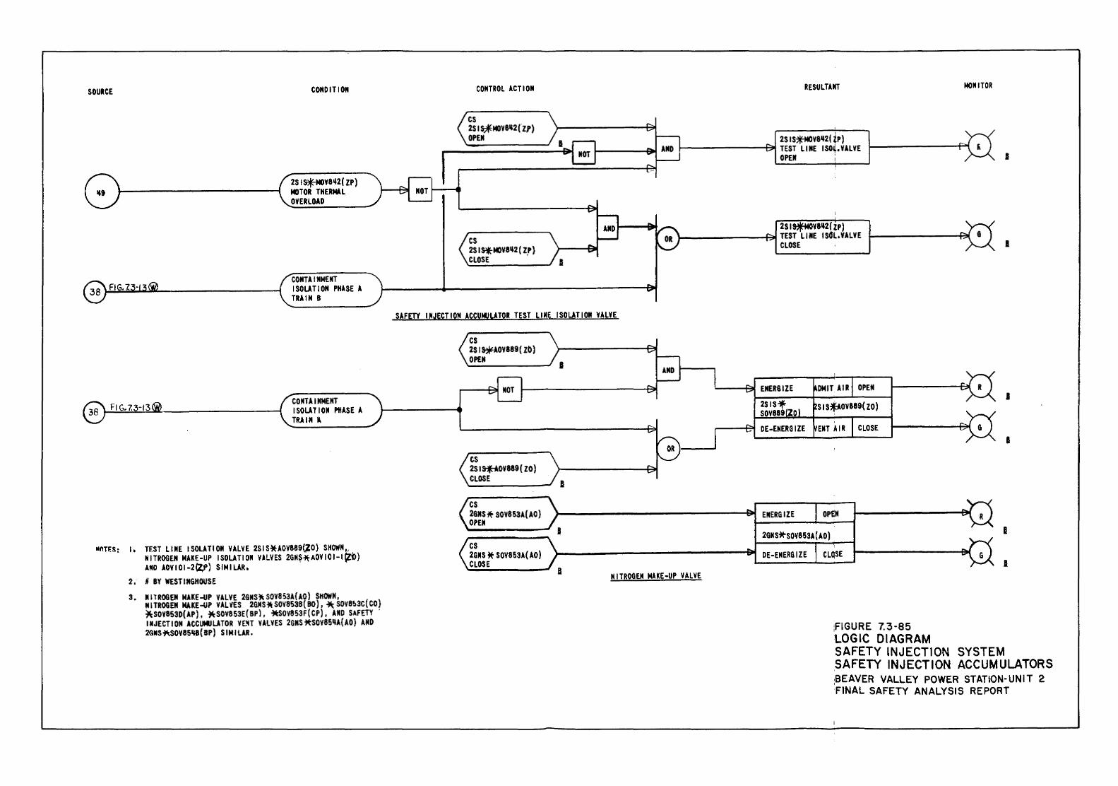
SOURCE CONDITION
2SI~V8~2(ZP) MOTOR THERMlL OVERLOAD
COMTA I NMENT ISOLATION PHASE A TRAIN B
~----------------~ CONTAINMENT ISOLATION PHASE A TRAIN l
11nr'"s: I , TEST L1 ME I SOLATION VALVE 2S I S·~UOV889~0) SHOWN,, NITROGEN MAKE-UP ISOLATION VALVES 2GN$~AOVIOI-I~O) AND AOVIOI-2~) SIMILAR,
2; I BY WESTINGHOUSE 3. NIT ROGEM MAKE -uP VALVE 2GNS~ SOVB 53 A( AQ) SHOWN,
N I TROGEM MUE -uP VALVES 2GNS * SOY8538 ( 80) , ~ SOVB&3C (CO) ~SOV853D(AP), ~SOV853E(BP}, +tSOVB53F(CP), AMO SAFETY ' INJECTION ACCUMULATOR Vt~T VALVES 2GNSitSOVBSIIA{AO) AND 2GNS~SOV85118(BP) SIMILAR.
CONTROL ACTION
cs 2SISjfMOV8112(Z1) OPEN
cs 2S I*MOV8112( ZP} CLOSE ,
RESULTANT
2SIS~V8112(tP) 1-------~ TEST LINE ISO~.YALVE
OPEN !
2SI~V8112(ZP) l---------+~ TEST Ll HE I S4l., VALVE
CLOSE
MONITOR
I
I
SAFETY INJECTION ACCUHUL!TOR TEST LINE ISOLATION VALVE
cs 2SI~AOV889(Zb} OPEN
cs 2SI'*"OV889(ZO) CLOSE
cs 2GMS '* SOVB53A( AD) OPEN
cs 2GNS * SOV853A( AD) CLOSE
I
I
I
I
OPEN
2GNS~SOV853A(AO) I
)--------------~ DE-ENERGIZE CLQSE
I NITROGEN MAKE-UP VALVE
;FIGURE 7.3-85 LOGIC DIAGRAM
I
SAFETY INJECTION SYSTEM SAFETY INJECTION ACCUMULATORS :BEAVER VALLEY POWER STATION-UNIT 2 FINAL SAFETY ANALYSIS REPORT
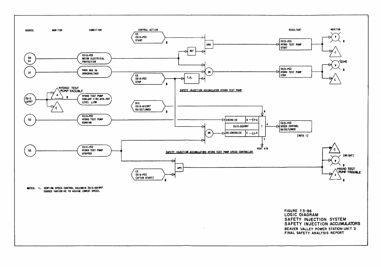
SOURCE MOMITOR CONDITION
2SIS-P22 MOTOR ELECTRICAL PROTECT lOll
mv aus 2A UNDERVOL TAGE
CONTRuL ACTION cs 2SIS-P22 START
cs ZSIS-P22 STOP
I
T.o.
RESULTANT
zs1:s-nz 1----------------AI HYDRO TEST PUNP ST RT
ZS1is-P22 1---------------..+::;;,~ HYDRO TEST PUMP
STOP
MONITOR
SAFETY INJECTION ACCUHUL!TOR HYDRO TEST PUNP
HYDRO TEST PUMP COOUJIT C I RC, WTR, POT LEVEL LOW HIC
2SIS-HIC9'7 RA I S E/LOIIIE R
f.;\,___ _______ --lc~~~:O~ST PUMP )1---------------v _RUNII!It& _ --------- ~--------~~
2SIS-P22
ZSIS-SOY9117
HYDRO TEST PUMP S.TOPPED SAFEJI INJ£CT!QN AccUMYLiTORS HYDRO TEST PUHP SPEED CONTROLLER
IOTES: I. VEMTIMG SPEED CONTROL SOLENOID 2SIS-SOV9'7 CAUSES VARIDRIYE TO ASSl~ LOWEST SPEED.
cs 2SIS-f'22 (AFT£1 START)
T
8
c
A 2SiiS-P22 r-----F=311 SPEED CONTROL
RAISE/LOWER
(NOTE I)
VENT AIR
FIGURE 7.3·86 LOGIC DIAGRAM
(BRIGHT)
I HYDRO TEST
PUMP TROUBLE
I
SAFETY INJECTION SYSTEM SAFETY INJECTION ACCUMULAlORS ~EAVER VALLEY POWER STATION-UNIT 2 f'INAL SAFETY ANALYSIS REPORT
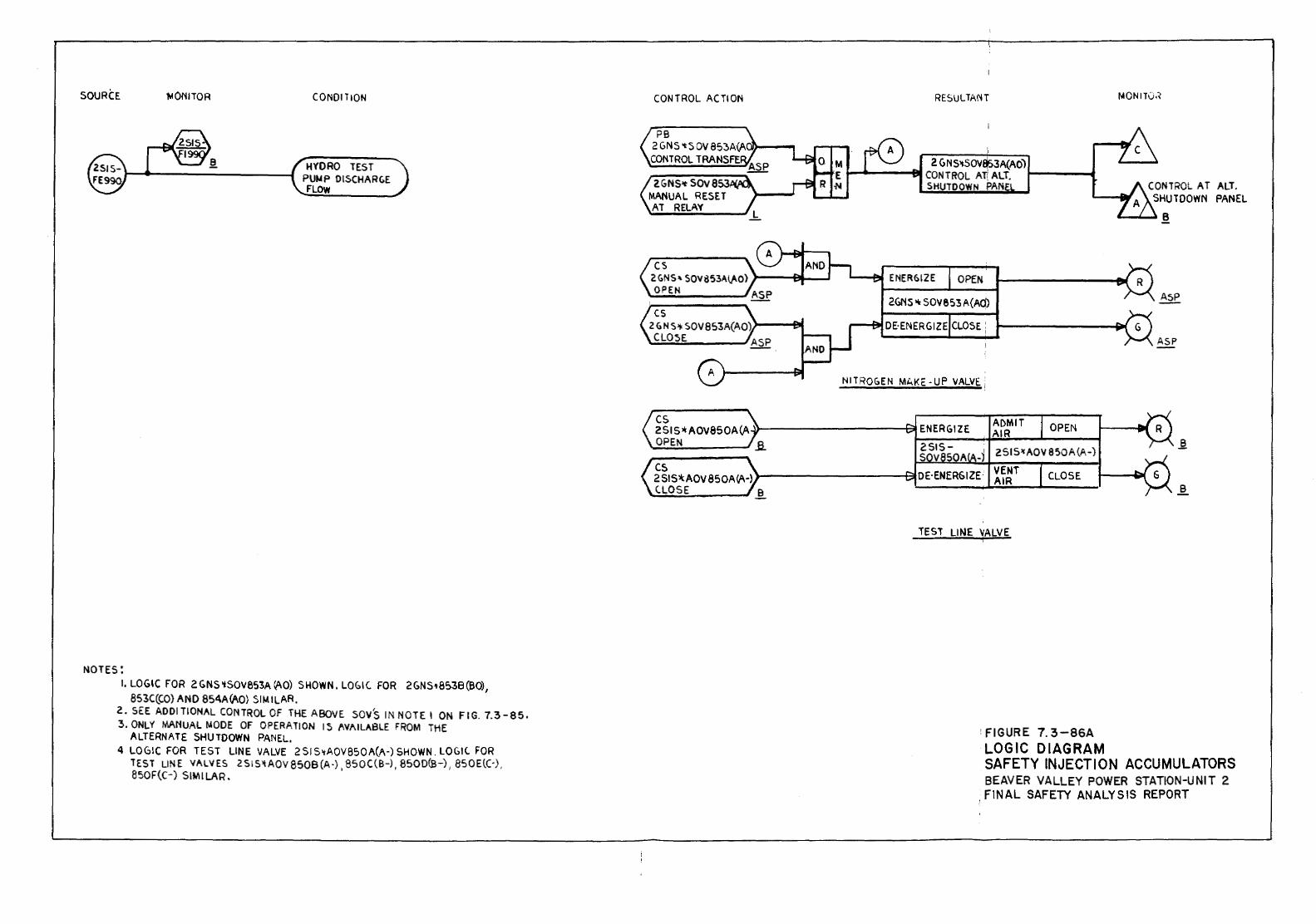
SOURCE ~QNITOR CONDITION
HYDRO TEST PUMP DISCHARC.E FLOW
NOTES: I, LOGIC FOR 2 GN S 'tSOV 853A ~0) SHOWN • LOG 1 C. FOR 2 GNS 't8538 (BO)
1 853C(CO) AND 85AA~O) SIMILAR.
2. SEE ADDITIONAL CONTROL OF THE ABOVE sov's IN NOTE 1 ON FIG. 7.3-85. 3. ONLY MANUAL MODE OF OPERATION IS MAILABLE FROM THE
ALTERNATE SHUTDOWN PANEL. 4 LOGIC FOR TEST LINE VALVE 2 Sl S>tAOV850A(f\-) SHOWN. LOGIC FOR
lEST LINE VALVES 251S'tAOV8508(A-). 850C(B-), 8500(B-) I 850E.(C·), 8SOF(C-) SIMILAR.
CONTROL ACTION
2 GNS>t SOV 853 MANUAL RESET AT RELAY
cs 2 G N S>F SOV 853A(AO) >---e& CLOSE.
RESULTANT
2 GNS>t.SO\I 3A(AO) i--.._-~8111 CONTROL AT!~ ALT. t----.....
SHUTDOWN PAN
.__-fiJI ENERGIZE OPEN
2GNS"' SOV8S3A(A(j)
---81 DE·ENERGIZE CLOSE i
NITROGEN MAKE· UP VALVE. i
TEST LINE \'ALVE
OPEN
CLOSE
'FIGURE 7. 3-86A LOGIC DIAGRAM
MONIT0.~
CONTROL AT ALT. SHUTDOWN PANEL
&....-'-~ B
ASP
SAFETY INJECTION ACCUMULATORS BEAVER VALLEY POWER STATION-UNIT 2 FINAL SAFETY ANALYSIS REPORT
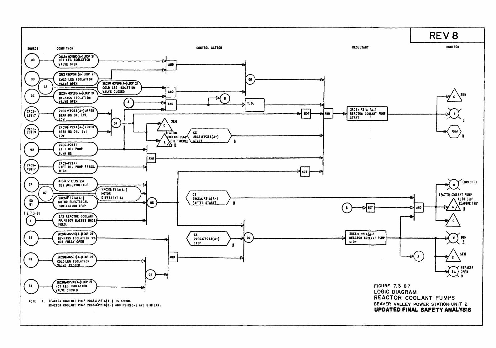
SOURCE COMOITIOM
211CS• N3YSIK)( 1.-) LOOP 21 HOT LE& lsdLATION VALVE OPEl
2JICS«MJ¥!'BI(A-)U.. 21 C~LD LEG ISOLATION
ALVE OPU
2RCS¥" P21 A(A-) LOWE.R BEARING OIL LYL LOW
2RCS-P21AI LIFT OIL PUMP RUNNING
2RCS-P21AI LIFT 0 I L PtJMP PRESS. 1--------~ HIGH
4160 V BUS 2A BUS UKDERYOLTAGE
2RC P21A( A-) MOTOR ELECTRICAL PROTECTION TRIP
2/3 REACTOR COOLANT
2RCS* P21 A( A-) MOTOR Dl FFERENT IAL
PP.III60Y BUSSES UMDEif--------~ FREQ.
2RCSt.MJY585( A-)l.D(f' 21 BY-PASS ISOLATION YV.t------------~ MOT FULLY OPEN
~~1.-)LOOP 21 1---{ HOT LEG ISOLATION
VALVE CLOSED
MOTE: I. REACTOR COOLAKT PUMP 2RCS* P21A(A-) IS SHOWN. Rf.I.CTOR C.OOWT PIJioiP 2RCS~P2li(B-) AIID P21C(C-) AilE SIMILAR.
COMTIOL ACTIOI
cs 2RCS.¥'P21i(A-) STOP
II
I
REVS RESULT AliT MONITOR
2RCS .. P21A A-l .,_.......,~ RElCTOit COO Alll PUMP l----------1-~
START 1
(SRIGHi)
REACTOR COOLUT PUMP AUTO STOP
REACTOR TRIP c.-.-..- I
2RCS • P21 A(1A- \ DIN !
RUCTOR CO~.t.ltT PUMP 5----..... ------+--at STOP I
FIGURE 7.3-87 LOGIC DIAGRAM
BREAlER OPEl B
REACTOR COOLANT PUMPS BEAVER VALLEY POWER STATION-UNIT 2 UPDATED FINAL SAFETY ANALYSIS
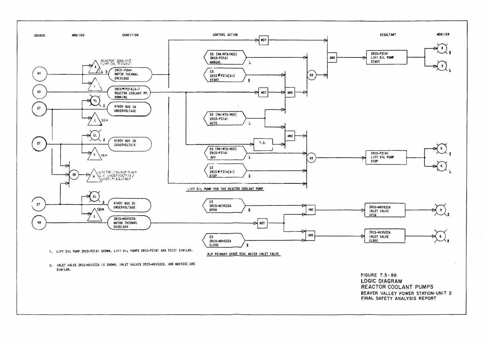
SOURCE lo!ONITOR CONDITION
It 160V BUS 28 Uiii1ERVOLTA2E
lti60V BUS 2C UNOERVOLTAGE
CONTROL ACTION
SS {MAINTAINED) 2RCS-P21AI OFF
T.O.
LIFT OIL PUMP FOR THE REACTOR COOLANT PUMP
cs 2RCS-M{1VS 22A OPEN
2RCS-MOVS22A MOTOR THERMAL OV ERLOAO 1------------------------------------------~l----_.
--------- L----f;l..r---,
1. LIFT OIL PUMP 2RCS-P21A1 SHOWN, LIFT O!L PUMPS 2RCS-P21Bl ANO P21C1 SIMILAR.
2. INLET VALVE 2RCS-MOV522A IS SHOWN, INLET VALVES 2RCS-MOV522B. ANO MOV522C ARE SIMILAR.
cs 2RCS-MOV522A CLOSE
R~P PRIMARY GRADE SEAL WATER INLET VALVE
RESUL TAIIT
2RCS-P21Al LIFT OIL PUMP STOP
2RCS-Io!OV522A lliLET VALVE OrEN
7RCS-IoiDVS22A INLET VALVE CLOSE
FIGURE 7.3-88 LOGIC DIAGRAM REACTOR COOLANT PUMPS
i«llll fOR
aEAVER VALLEY POWER STATION-UNIT 2 ~INAL SAFETY ANALYSIS REPORT
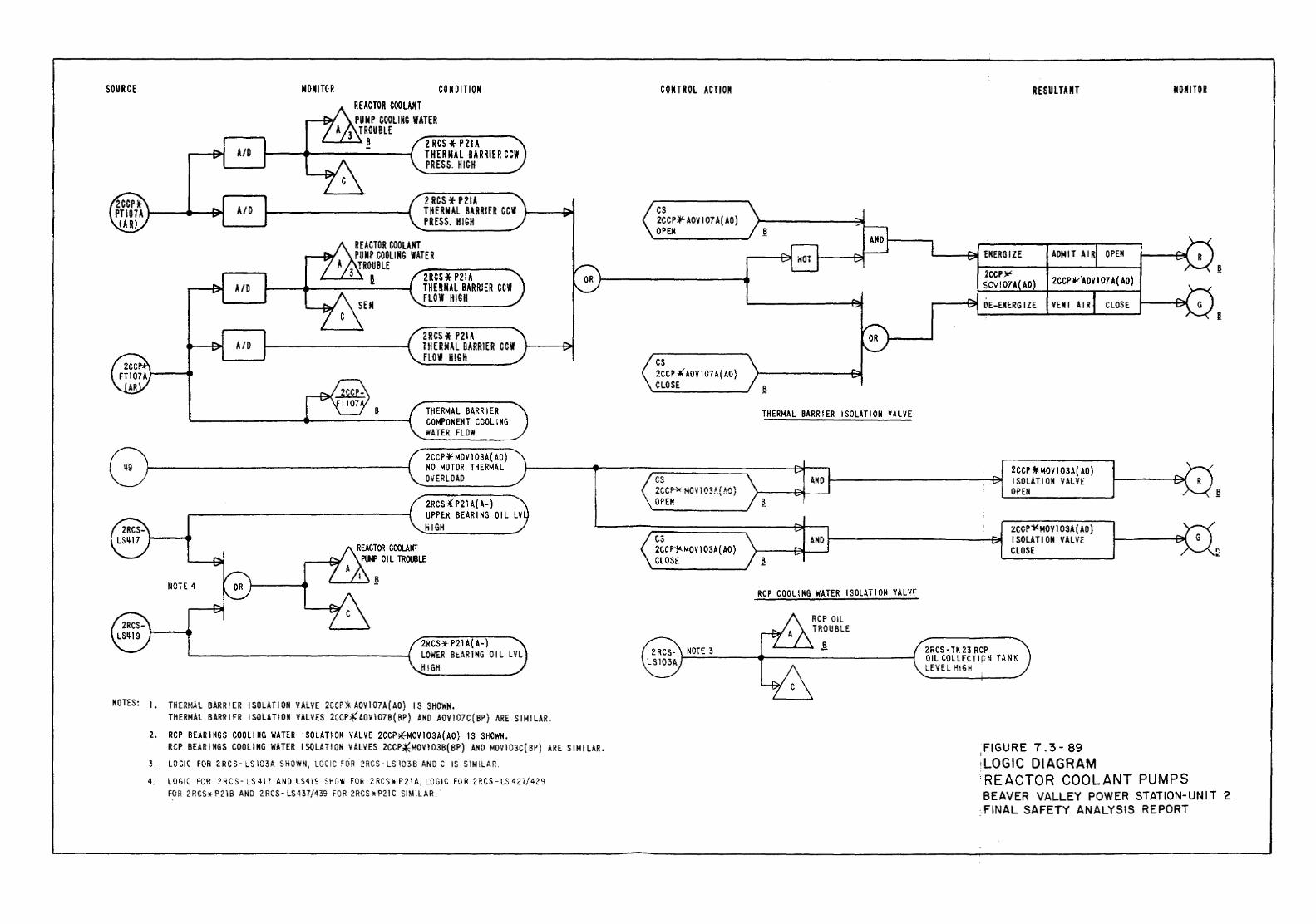
SOURCE
NOTE 4
NON I TOR CONDITION REACTOR COOLANT PO N P COOLING WATER
3 TROUBLE .._....._ ..... 8 Z RCS * PZIA
THERMAL BARRIER CCW PRESS. HIGH
2 RCS * P21A THERMAL BARRIER CC'I PRESS. HIGH
ZRCS* P21A THERMAL BARRIER CCII FLOW HIGH
ZRCS* P21A TH ERNAL BARRIER CC'I FLOW H!G H
THERMAL BARRIER COMPONENT COOLING WATER FLOW
2CCP¥ r-!OV I 03A( AO) NO MOTOR THERMAL OVERLOAD
2RCS i P21 A( A-) UPPlR BEARING OIL LV liiGH
2RCS*- P21 A( A-) LOWER BtARING OIL LVL HIGH
NOTES: I. THE,~M.I.L BARR!ER ISOLATION VALVE 2CCP1HOV107A(AO) IS SHOWN. THERMAL BARRIER ISOLATION VALVES 2CCP~AOV107B(BP) AND AOV107C(BP) ARE SIMILAR.
2. RCP BEARINGS COOLING WATER ISOLATION VALVE 2CCP~MOVI03A(AO) IS SHOWN. RCP BEARINGS COOLING WATER ISQLAT!ON VALVES 2CCP~MOV103B(BP) ANO MOV103C(BP) ARE SIMILAR.
3. LOGIC FOR 2 RC S- LS 103A SHOWN, LOGIC FOR 2RCS- LS 103 B AND C IS SIMILAR.
4. LOGIC FOR 2.RCS- LS4l7 AND LS419 SHOW FOR 2RCS* P2.1A, LOGIC FOR 2RCS-LS42.7/429 FOR 2 RCS!!- P 21 B AND 2 RCS-LS437 /439 FOR 2RCS * P21 C SIMILAR ..
COJHROL ACTION
cs 2CCP~AOVI07A(AO) OPEH
cs 2CCP }I{ AOV 107 A( AO) CLOSE
cs 2CCP.X MOV I 03A( VJ) OPEN
cs 2CC Pi'- MOV 1 03A ( AO) CLOSE
THERMAL BARRIER ISOLATION VALVE
RCP COOLING WATER ISOLATION VALV~
RCP OIL TROUBLE
! 2RCS- TK 2.3 RCP
RESULTANT
ADMIT AIR OPEN
2CCP .JV"AOV I 07 A( AO)
VENT AIR CLOSE
2CCP * "'OV I 03A( AO) ISOLATION VALvt OPEN
2CCP1(HQV103A(AO) ISOLATION VALVE CLOSE
OIL COLLECT I ptl TANK LEVEL HIGH
FIGURE 7. 3- 89 ;
,LOGIC DIAGRAM
NOM I TOR
.REACTOR COOLANT PUMPS BEAVER VALLEY POWER STATION-UNIT 2
. FINAL SAFETY ANALYSIS REPORT
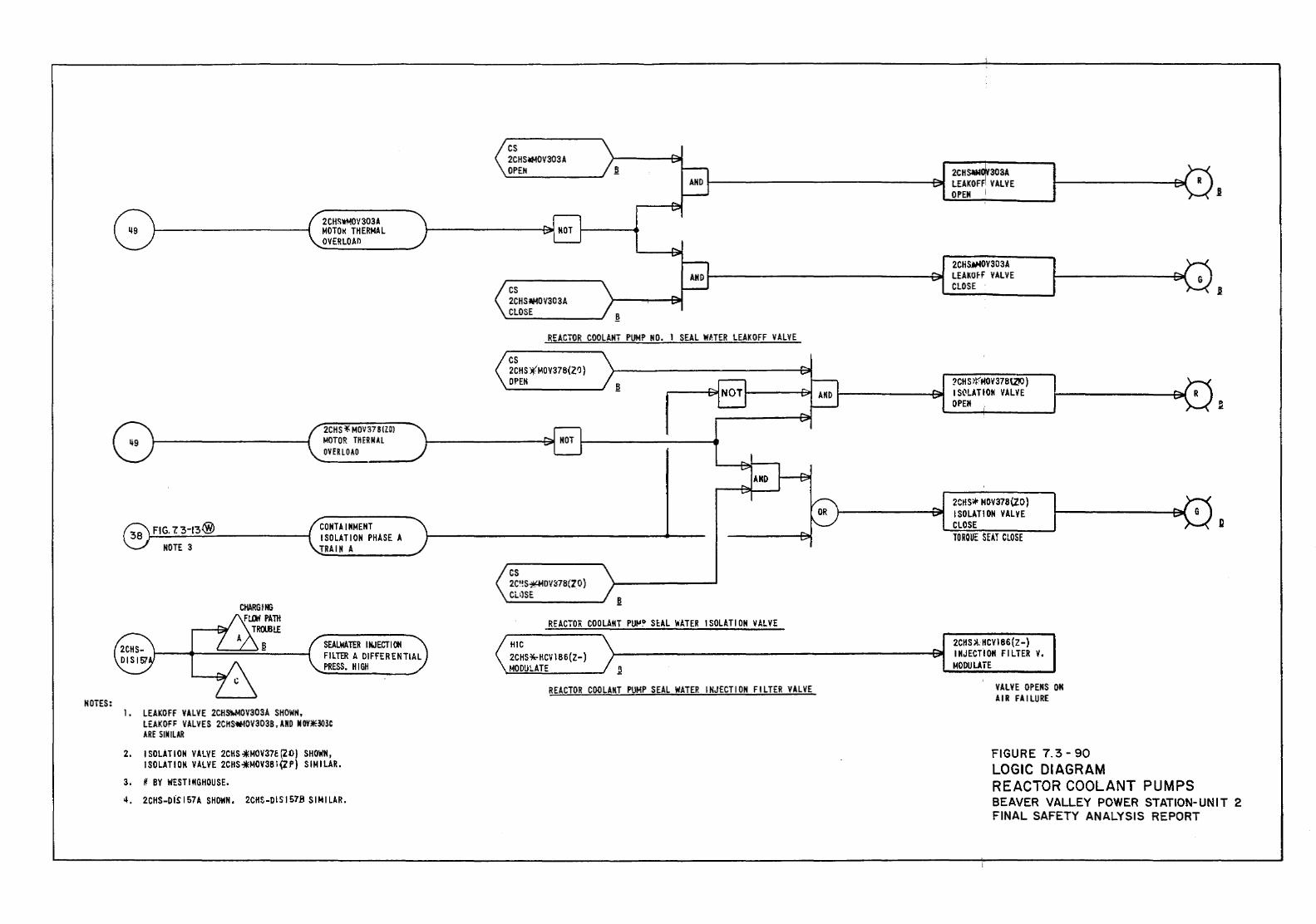
MOTES:
FIG. 7. 3-13® NOTE 3
1. LEAKOFF VALVE 2CH~OV303A SHOWN,
2CHS~OV303A MOTOI< THERMAL OVERLOAO
2CHS *MDV 37 8 IZDJ MOTOR TIHRN.U OVERLOAD
CONTAINMENT ISOLATION PHASE A TRAIN A
SEALWAID INJECTION FILTER A DIFFERENTIAL PRESS. HIGH
LEAK OFF VALVES 2CHS¥10V303B, AND II DY.liE303C ARE SIMILAR
2. ISOLATION VALVE 2CHS *MOV37E (20} SHOWN, ISOLATION VALVE 2CHS*MOV381(ZP) SIMILAR.
3. ~ BY WESTINGHOUSE • .-, 2CHS-DIS I 57 A SHOWN, 2CHS-DI S 157B SIN I LAR.
cs 2CHSoliMOV303A OPEN
cs 2CHSAMOV30 3A CLOSE
2CHsaN 303A 1------------------F~ LEAKOF ' VALVE
OPEN
2CHS»>OV303A LEAKO~f VALVE CLOSE
REACTOR COOLANT PUMP MO. 1 SEAL W}.TER LEAKOFF VALVE
cs 2CHS )(MOV378\.21J) OPEN
cs 2C'!S~OV~78(ZO) CLllSE
REACTO!i COOLANT PUt<'~ SUL \'lATER ISOLATION VALVE
?CH S ~r-"'OV 37BQIO) I St:ILATION VALVE OPEN
2CIIS* HOV378\2.0) ISOLATION VALVE CLOSE TOROUE SEAT CLOSE
HIC 2CHS*-HCV 186(Z-) MODULATE
2CHS)!.HCV\86(Z-) ~----------------------I::SJII INJECTION FILTER V.
MODULATE
REACTOR COOLANT PUMP SEAL WATER INJECTION FILTER VALVE VALVE OPENS OM AIR FAILURE
FIGURE 7.3- 90 LOGIC DIAGRAM REACTOR COOLANT PUMPS BEAVER VALLEY POWER STATION-UNIT 2 FINAL SAFETY ANALYSIS REPORT
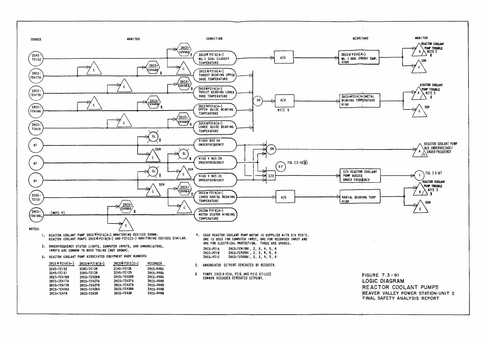
SOURCE
NOTES:
MONITOR
1. REACTOR COOLA~T PUMP 2RCS~P21A(A-} MONITORING DEVICES SHOWN. REACTOR COOLANT PUMPS 2RCS~P21B(B-} AND P21C(C-} MONITORING DEVICES SIMILAR.
2. UNDERFREQUENCY STATUS LIGHTS, COMPUTER INPUTS, AND ANNUNCIATORS, INPUTS ARE COMMON TO BOTH TRAINS (NOT SHOWN}.
3. REACTOR COOLANT PUMP ASSOCIATED EQUIPMENT MARK NUMBERS:
2RCS ,( P21 A( A-} 2RCS~P21 B( B-) 2RCS*"P21 C( C-) RECORDER 2CIIS-TE132 2Ct1S-TE131 2RC'i-TE~ 18B 2RCS-TE~17A
2RCS-TE~178 2RCS-TE~1BA
2RCS-TE~19
2CHS-TE129 2CHS-TE128 2RC5-TE~2BB 2RCS-TE!t27A 2RCS-TE~278 2RCS-TE~28 A 2RCS-TE~29
2CHS-TE126 2CHS-TE125 2RCS-TE~38B 2RCS-TE~37 A 2RCS-TE~37B 2RCS-TE~38A 2RCS-TE~39
2RCS-~~BA 2RCS-~~BA 2RCS-1P+BA 2RCS-~~BB 2RCS-~~BB 2RCS-~~BB 2RCS-~~BB
COMO ITl ON
2RCS'f P21 A( A- f NO. I SEAL LEAKOFF TEMPERATURE
2RCS*P21 A( A-} THRUST BEARING UPPER 1---~ SHOE TEMPERATURE
2RCS¥f21 A{ A-) THRUST BEARING LOWER L---Hf SHOE TEMPERATURE
2RCS -¥f>21 A{ A-) UPPER GUIDE BEARING TEMPERATURE
2RCHP21 A{A-) LOWER GUIDE BEARING t..---+31 TEMPERATURE
~160V BUS 2A UN OER FREQUENCY
ltl60 V BUS 28 UNDERFREOUENCY
~160 V BUS 2C Ull OERF R EOUEKCY
2RCS ¥ P21 A{ A-) LOWER RADIAL BEARING J-------f~ TEMPERATURE
21i:CS¥ P21 A(A-) MOTOR STATOR WINDING TEMPERATURE
A/0
A/0
R'HE 6
A/0
RESULTANT
2RCS¥ p 21 A( AL) 1---------~ NO. I SEAL LfAtOFF TEMP. 1-----.
HIGH ,
2RCS~21A(Af)METAL t----------8!1 BEARING T£MPERATURE
HIGH .
2/3 REACTOR COOLANT PUMP BUSSES UNDER FREQUeNCY
1---------et RADIAL BEARING TEMP HI Gil .
MONITOR REACTOR COOlANT
PlN' TRruiL£ NOTE 5
!1:
R EACT(I! COOLANT PIW TRruJLE
NOTE 5 .!!
REACTOR CQOLANT PUMP BUS UNDERVOLTAGE/
UNDER FRECUENCY
FIC. 7.3·87
~. EACH REACTOR COOLANT PUMP MOTOR IS SUPPLIED WITH SIX RTD'S.
5.
ONE IS USED FOR COMPUTER INPUT, ONE FOR RECORDER INPUT AND ONE FOR ELECTRICAL PROTECTION, THREE ARE SPARES. 2RCS-P21A 2RCS-P21 B 2RCS-P21C
2RCS-TE~IBBI, 2, 3, ~. 5, 6 2RCS-TE~28BI, 2, 3, ~. 5, 6 2RCS-TE~38BI , 2, 3, ~. 5, 6
AN RUNCIATOR SET PO I NT CE R ERATE D BY RECOROE R.
6. PUMPS 2RCS*P21A, P21B, AND PZIC UTILIZE COM M 0 N RECORDER GENE RATED SET POINT.
FIGURE 7.3-91 LOGIC DIAGRAM :REACTOR COOLANT PUMPS :SEAVER VALLEY POWER STATION-UNIT 2 !FINAL SAFETY ANALYSIS REPORT
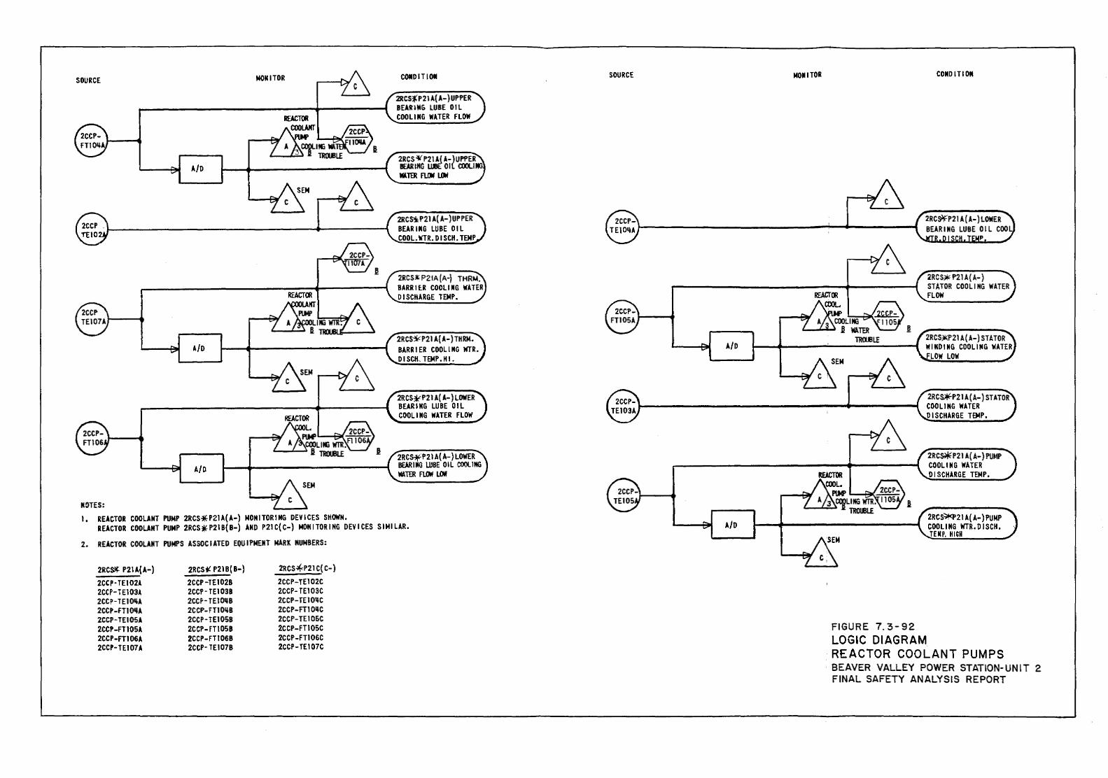
SOURCE MOtiiTOR
A/0
A/D
A/0
MOTES: I. REACTOR COOLANT PUMP 2RCS~P21A(A-) MONITORING DEVICES SHOWN.
COIDITIOI
2RCS*'P21 A( A-) UPPER BEARIIIG LUBE OIL COOLING WATER FLOW
2RCS~P2JA(A-\UPPER BEAR lNG l.UIIe:' 0 I ( COOLII«i MATER FUltl l.4rl
2RCS'*P21 A( A-) UP PER BEARING LUBE OIL COOL.WTR.DISCH.TEMP
2RCS~P21A(A-) THRM. BARRitR COOLING WATER DISCHARGE TEMP.
2RCS~P21A{A-)THRM.
BARRIER COOLING WTR. DISCH. TEMP. HI.
2RCS~P21A(A-)LOWER BEARING LUBE OIL COOLING WATER FLOW
2RC~P21A(A-)LOWER BEARING lllBE OIL COOLING WATER FUJtrl LOW
REACTOR COOLANT PUMP 2RCS~P21B(B-) AND P21C{C-) MONITORING DEVICES SIMILAR.
2. REACTOR COOLANT PUMPS ASSOCIATED EQUIPMENT MARK NUMBERS:
2RC~ P21A{A-) 2CCP-TEIOV. 2CCP- T E103A 2CCP-TEIO!lA 2CCP-FTIO'lA 2CCP-TE105A 2CCP-FT105A 2CCP-FT106A 2CCP-TE107A
2RCSi! P21 B( B-) 2CCP -TE I 02B 2CCP-TEID3B 2CC~·TEID!lB
2CCP-fTID~B 2CCP-TE105B 2CCP- FT I OSB 2CCP-FTID68 2CCP- TE1078
2RCS~P21 C{ C-) 2CCP-TE102C 2CCP- TEl 03C 2CCP-TE I OllC 2CCP-FTI~C 2CCP-TE106C 2CCP-FTIOSC 2CCP-FT106C 2CCP- TEl 07C
SOURCE MDIII TOR
A/D
A/D
COIIDITIOM
2RCS*P21A{A-) STATOR COOLING WATER FLOW
2RCS;KP21A{A-)STATOR WINDING COOLING WATER
I
FIGURE 7. 3-92 LOGIC DIAGRAM
LOW LOW
2RC~P21A{A-)STATOR COOLING WATER DISCHARGE TEMP.
2RC~P21A{A-)PUMP COOLING WATER 0 I SCHARGE TEMP.
2RCS~21A(A-)PUMP COOLING WTR.DISCH. TEMP. HICH
REACTOR COOLANT PUMPS BEAVER VALLEY POWER STATION-UNIT 2 FINAL SAFETY ANALYSIS REPORT
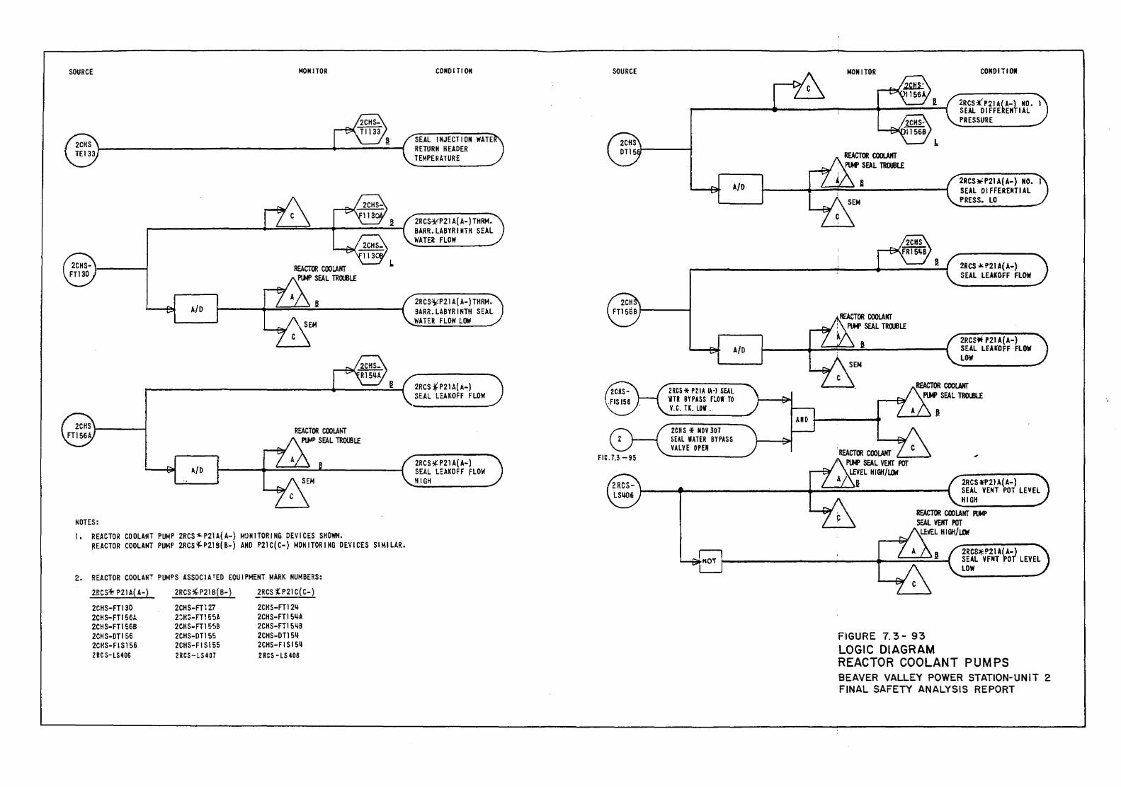
SOURCE MONITOR
A/D .!!
A/D
NOTES: 1. R EAC TOR COOLANT PUMP 2RCS "- P21 A( A-) M0N 1 TOR I NG DE VI CES SHOWN.
~EACTOR COOLANT PUMP 2RCS~P21B(B-) AND P21C(C-) MONITORING DEVICES SIMILAR.
2. REACTOR COOLANT PUMPS ASSOCIATED EQUIPMENT MARK NUMBERS: 2RCS* P21 A( A-) 2RCS ~P21 B( B-) 2RCS t P21 C( C-)
2CHS-FT130 2CHS-FT127 2CHS-FT12~
2CHS-FT156t. 2:;H:>-FT15 5A 2CHS-FT1 S~A 2CHS-FT156B 2CHS-FT155B 2CHS-FT151tB 2CHS-DT156 2CHS-DT155 2CHS-DT1 5~ 2CHS-FIS156 2CHS-FIS155 2CHS-FIS15~
2RC S-LS406 2RCS- LS407 2 RCS- LS 408
CONOI TlON
SEAL INJECTION WAlE RETURN HEADER TEMPERATURE
2RCS~P21A(A-)THRM. BARR.LABYRINTH SEAL WATER FLOW
2RCS~P21A(A-)TKRM . BARR.LABYRINTH SEAL WATER FLOW LOW
2RCS f P21 A( A-) SEAL LEAKOFF FLOW
2RCS~ P21 A( A-) SEAL LEAKOFF fLOW HIGH
SOURCE
A/D
A/D
2RCS* P 21 A IA-J SEAL WTR BYPASS FLOW TO V.C. TK. LOW .
2CHS + NOY30l SEAL WATER BYPASS VALVE OPEN
MONITOR
B
.!!
. REACTOR COOlANT '----J PlW SEAL VEKr POr
LEVEL H IGII/U1fl ~
CONDITION
2RCS-:t'P21AkA-t NO. I SEAL OIFFE EN IAL PRESSURE
2RCS~P21A(A-) NO. I SEAL DIFFERENTIAL PRESS. LO
2RCS.~<P2lA(A-) SEAL LEAKOFF FLOW
2RCSJt P21 A(A-) SEAL LEAKOFF FLOW LOW
2RCS *P21 A{ A-) SEAL VENT POT LEVEL HIGH
REACTOR COOLANT RM' SEAL VEHT POr
LE\'EL H I GH/ J.Oif
FIGURE 7. 3- 93 LOGIC DIAGRAM
2RCS;t.P21 A{ A-) SEAL YFNT POT LEVEL LOW
REACTOR COOLANT PUMPS BEAVER VALLEY POWER STATION-UNIT 2 FINAL SAFETY ANALYSIS REPORT
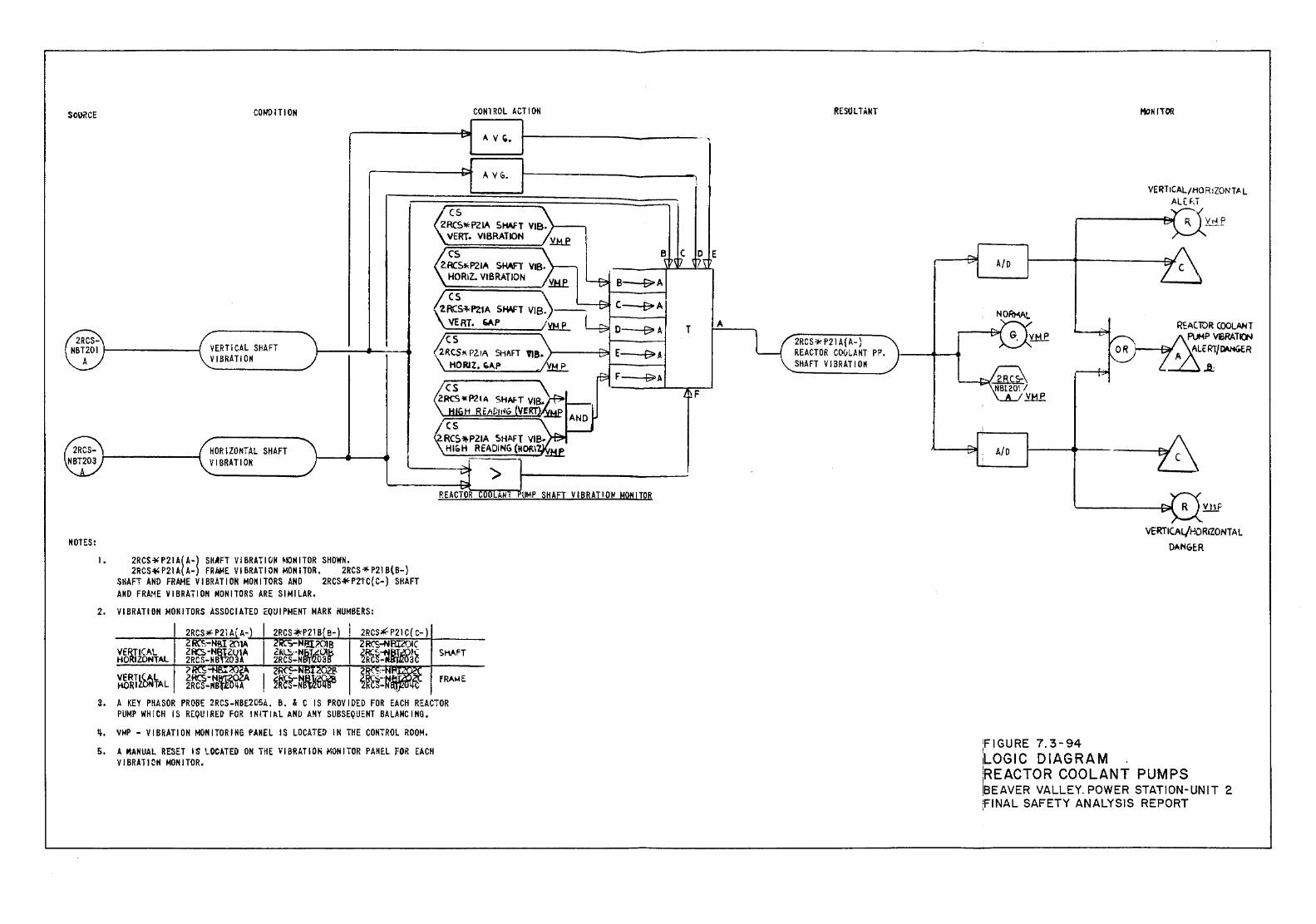
MOTES: 1.
HORIZONTAL SHAFT VIBRATION
2RCS-¥ P21 A( A-) SHAFT VI BRAT I ON MOH I TOR SHOWN. 2RCS~ P21 A( A-) FR AidE VI BRA Tl ON MOM I TOR, 2RCS 'H2! B(B-)
SHAFT AND FRAME VIBRATION MONITORS AND 2RCS~P1tC{C-) SHAFT AND FRAt~E VI BRAT I ON MONITORS ARE SJ MILAR.
2. VIBRATION MONITORS ASSOCIATED EQUIPMENT MARK NUMBERS:
VERTICAL HORIZONTAL
VERTICAL HORIZONTAL
Si-~,i.FT
fRAME
3. A KEY PHASOR PROBE 2RCS-NBE2GSA, B. & C IS PROVIDED FOR EACH REACTOR PUMP WHICH IS REQUIRE~ FOR !NITI~L AND ANY SUBSEQUENT BALANCING,
~. VMP - VIBRATION MONITORING PANEL IS LOCATED IN THE CONTROL ROOM.
5. A MANUAL RESET IS LOCATE~ ON THE VIBRAT\0~ MONITOR PANEL FOR EACH VJBRATI~H MONITOR.
UMP SHAfT VIBRATION HQNITOR
A/D
;FIGURE 7.3-94 LOGIC DIAGRAM .
VERTICAL/P.ORIZONT A L DANGER
iREACTOR COOLANT PUMPS !BEAVER VALLEY. POWER STATION-UNIT 2 fiNAL SAFETY ANALYSIS REPORT
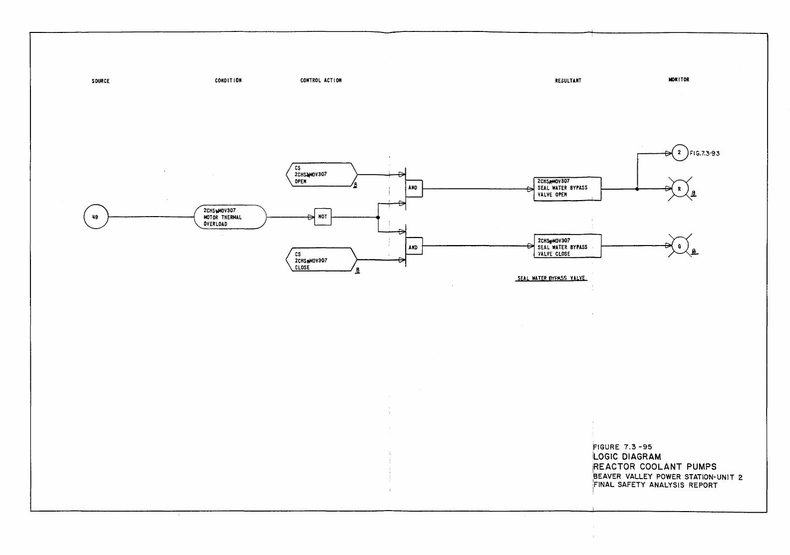
SOURCE CONDIT ION
2CHS~OV307 MOTOR THERMAL OVERLOAD
COIITROL ACT I ON
cs 2CH~V307 OPEN
cs 2CHS;Wo!OV307 CLOSE
RESULTAIIT
2CH~V307
1-----------~ SEAL 'fiATER BYPASS VALVE OPEN
2CHstMOV307 1------------~ SEAL 'fiATER BYPASS
'IALVE CLOSE
SEAL 'fiATER BYp,5S VALvE
!FIGURE 7.3 -95 iLOGIC DIAGRAM
MOICITOR
FIG.7.3-93
iREACTOR COOLANT PUMPS 'SEAVER VALLEY POWER STATION-UNIT 2 I ;FINAL SAFETY ANALYSIS REPORT .,
BVPS-2 UFSAR Rev. 0
7.4-1
7.4 SYSTEMS REQUIRED FOR SAFE SHUTDOWN The functions necessary for safe shutdown are available from instrumentation channels that are associated with the major primary and secondary systems of the nuclear steam supply. These channels are normally aligned to serve a variety of operational functions, including start-up end shutdown as well as protective functions. However, procedures for securing and maintaining Beaver Valley Power Station - Unit 2 (BVPS-2) in a safe condition can be instituted by appropriate alignment of selected components in the nuclear steam supply. The discussion of these systems, together with the applicable codes, criteria, and guidelines, is found in other sections of this safety analysis report. In addition, the alignment of shutdown functions associated with the engineered safety features, which are invoked under postulated limiting fault situations, is discussed in Chapter 6 and Section 7.3. Two kinds of shutdown conditions, both capable of being achieved with or without offsite power, are addressed in this section: hot standby and cold shutdown. Hot standby is a stable condition of the reactor achieved shortly after a programmed or emergency shutdown of BVPS-2. Although hot standby is the safe shutdown design basis for BVPS-2, safety grade provisions have been incorporated in the design of the plant to facilitate cold shutdown. Cold shutdown is a stable condition of the plant achieved after the residual heat removal (RHR) process has brought the primary coolant temperature below 200°F. For a description of the RHR system and how it is used for cold shutdown, refer to Section 5.4.7. For either case of the safe shutdown, that is, hot standby or cold shutdown, the reactivity control systems maintain a subcritical condition of the core. The plant Technical Specifications explicitly define both hot standby and cold shutdown conditions. The electrically-powered instrumented and controlled systems and equipment which are required to be aligned for achieving and maintaining cold shutdown without offsite power, with main control room occupancy, with a single random failure, and with limited operator action outside of the control room are a minimum set listed as follows. These systems and equipment are available from inside the main control room:
1. Emergency, vital electrical power supply,* 2. Auxiliary feedwater system (AFWS),* 3. Residual heat removal (and isolation) system, 4. Borated water inventory supply to centrifugal charging pump
suction via the emergency boration path and the boric acid transfer pump, which takes suction directly from the boric acid tank through a normally open path when the emergency boration valve is opened. In addition, there is an
BVPS-2 UFSAR Rev. 16
7.4-2
alternate source of boration supplied to the charging pump suction from the refueling water storage tank,
5. Redundant discharge system from the centrifugal charging
pumps, both having throttling capability through safety injection lines,
6. Power operated relief valves (PORVs) for reactor coolant
system (RCS), 7. Pressurizer safety valves,* 8. Decay heat removal, using steam line atmospheric dump valves
(ADVs) and limited operator action, as well as steam generator safety valves,*
9. Safety grade head vent letdown to pressurizer relief tank
isolation system, which will withstand an active failure, 10. Reactor protection system,* and 11. Redundant accumulator isolation venting, in addition to the
normal isolation valves. *The minimum number of instrumentation and control functions permitted under nonaccident conditions, which are required to be aligned for maintaining hot standby. They are available outside as well as inside the main control room, and accomplish the following functions:
1. Prevent the reactor from achieving criticality in violation of the Technical Specifications,
2. Provide an adequate heat sink such that design and safety
limits are not exceeded, 3. Pressurizer pressure control, and 4. Provide RCS inventory control.
7.4.1 Description Instrumentation and control provisions associated with the hot standby systems are identified in Sections 7.4.1.1 and 7.4.1.2. The equipment and services for cold shutdown are identified in Section 7.4.1.4. Loss of the monitoring instrumentation and local controls outside the main control room and normal automatic systems are not assumed coincident with control room evacuation. For applicable drawings, refer to Section 1.7.
BVPS-2 UFSAR Rev. 12
7.4-3
7.4.1.1 Monitoring Indicators The characteristics of these indicators, which are provided outside as well as inside the main control room, are described in Section 7.5. The necessary indicators are as follows:
1. Water level indicator (wide range) for each steam generator, 2. Pressure indicator for each steam generator, 3. Pressurizer water level indicator, and 4. Pressurizer or RCS pressure indicator.
The remote shutdown monitoring instrumentation channels, with readouts displayed external to the control room, are shown in Table 7.4-3. 7.4.1.2 Controls 7.4.1.2.1 General Considerations
1. The turbine is tripped (Note that this can be accomplished at the turbine as well as in the main control room). This closes the turbine steam stop valves.
2. The reactor is tripped (Note that this can be accomplished at
the reactor trip switchgear as well as in the main control room).
3. All automatic systems continue functioning (discussed in
Section 7.7). 4. Selected controls for safe shutdown are located inside as
well as outside the main control room. Those controls located outside the control room are provided with a control transfer pushbutton which transfers control from the main control room to the emergency shutdown panel (ESP). Placing the pushbutton in the local operating position is annunciated inside the main control room.
7.4.1.2.2 Pumps and Compressors
1. Auxiliary feedwater pumps
In the event of feedwater pump stoppage due to a loss of electrical power, the auxiliary feedwater pumps start automatically. The pumps can be started manually at the ESP as well as inside the main control room.
2. Charging pumps
Start/stop motor controls for these pumps are located on the ESP as well as inside the main control room.
BVPS-2 UFSAR Rev. 16
7.4-4
3. Boric acid transfer pumps
Start/stop motor controls for these pumps are located on the ESP as well as inside the main control room.
4. Service water pumps
Start/stop motor controls for these pumps are located on the ESP as well as inside the main control room.
5. Component cooling water pumps
Start/stop motor controls for these pumps are located on the ESP as well as inside the main control room.
6. Instrument air compressors
These compressors start automatically on low air pressure. However, loss of instrument air does not prevent the operation of the minimum systems necessary for hot standby.
7.4.1.2.3 Emergency Diesel Generators These units start automatically following a loss of normal ac power. Manual controls for emergency diesel generator start-up are also provided locally at the diesel generators as well as inside the main control room. 7.4.1.2.4 Valves and Heaters
1. Charging flow control valves
Charging flow control valves fail open upon loss of instrument air. Subsequent control of the flow can be maintained through control of the charging pumps at the ESP.
2. Letdown orifice isolation valves
Manual control is provided both at the ESP and inside the main control room.
3. Auxiliary feedwater control valves
Controls for these valves are located at the ESP and inside the main control room.
4. Steam generator safety valves and steam line atmospheric dump
valves
a. Spring-loaded safety valves
The safety relief valves on each steam header are located upstream of the isolation valves. They are spring-loaded, self-opening on an increase in pressure in the steam header.
BVPS-2 UFSAR Rev. 16
7.4-5
b. Atmospheric dump valves
The ADVs are located upstream of the isolation valves, one on each steam header. Control of these valves is automatic by steam line pressure, with remote manual control by adjustment of the pressure set point from the main control room as well as at the ESP. In addition, local manual operators are provided in the event of complete loss of automatic control.
5. Pressurizer heater control
On-off control with selector switches is provided for two backup heater groups at the ESP. The heater groups are connected to separate buses, such that each group can be powered from separate emergency diesel generators in the event of loss of offsite power (LOOP). The controls are grouped with the charging flow controls at the ESP and duplicate functions are available in the main control room.
7.4.1.3 Main Control Room Evacuation The instrumentation and controls listed in Sections 7.4.1.1 and 7.4.1.2, which are used to achieve and maintain a safe shutdown, are available in the event an evacuation of the main control room is required. These controls and instrumentation channels, together with the equipment and systems listed in Section 7.4.1.4, identify the potential capability for cold shutdown of the reactor subsequent to a main control room evacuation through the use of suitable procedures. Control room evacuation shall not occur coincident with an abnormal operating condition (Condition II, III, or IV event) except the loss of offsite power. The emergency shutdown panel and the equipment used to maintain remote shutdown fulfill the single failure criterion. Normal control from the main control room would normally be expected to function under all conceivable events. In accordance with General Design Criterion (GDC) 19, provisions are made to control certain vital systems required for hot standby of the unit from a central location (ESP) (Table 7.4-1) outside the main control room in the event of inaccessibility of the main control room (Section 6.4 on main control room habitability). The design bases for establishing the functional requirements to provide hot shutdown capability from the ESP are as follows:
1. As previously stated, inaccessibility of the main control room shall not occur simultaneously with or subsequent to an accident condition other than a LOOP.
BVPS-2 UFSAR Rev. 0
7.4-6
2. The main control board, although not necessarily remaining operable, shall not be affected because of main control room inaccessibility to the extent that the control board generates spurious or unwanted control signals which would prevent hot standby from the ESP.
3. A sufficient quantity of auxiliary feedwater shall be
available for decay heat removal until such time as the RHR system can be placed in operation. The AFWS is described in Section 10.4.9.
In the event that a main control room evacuation is required, the controls and monitoring instrumentation, which are located on the ESP, will be utilized. The design criteria for control room evacuation includes single failure and coincident loss of offsite power. Power sources for all Class 1E control circuitry of pumps and valves are the same power sources as those used in the main control room. Separation of redundant train-related and non-Class 1E circuits is maintained by barriers or appropriate air space. All control equipment (other than indicators) which is part of a Class 1E circuit meet the requirements of IEEE Standard 344-1975, "Seismic Qualification of Class 1E Equipment," and IEEE Standard 323-1974, "Qualifying Class 1E Equipment." Transfer of control to the shutdown panel is accomplished by the transfer pushbuttons and switches on the shutdown panel. Transfer separates all control from the control room. Reset (override) is accomplished by hand reset transfer relays at the local relay panel. In the event of an exposure fire, as defined in 10 CFR 50, Appendix R, the alternate shutdown panel (ASP) is designed to allow compliance with Branch Technical Position CMEB 9.5-1 and NUREG-0800, Section 9.5.1, as they apply to the instrumentation and relay room, cable spreading room, west communication room (ESP), and the cable tunnel. The switching capability of the ASP (Table 7.4-2) provides a means of alternate shutdown capability that bypasses all equipment and electrical cables located in the previously mentioned four fire areas. All electrical cables that pass through these areas and which are required for safe shutdown, are electrically removed from their circuits to ensure isolation of the affected fire area and allow independence of the ASP. The ASP will control one train of one redundant division of the Class 1E systems necessary for the safe shutdown of BVPS-2.
BVPS-2 UFSAR Rev. 0
7.4-6a
7.4.1.4 Equipment and Systems Available for Cold Shutdown
1. Auxiliary feedwater system pumps (Section 10.4.9), 2. Boric acid transfer pumps and tanks (Section 9.3.4), 3. Charging pumps (Section 9.3.4), 4. Service water system pumps (Section 9.2.1), 5. Main control room ventilation (Section 9.4.1), 6. Component cooling water pumps (Section 9.2.2.1), 7. Residual heat removal system pumps (Section 5.4.7), 8. Certain motor control centers and switchgear sections
associated with motors, valves, and heaters on this list (Section 8.1),
9. Controlled steam release and feedwater supply (Sections 7.7
and 10.4.9),
BVPS-2 UFSAR Rev. 0
7.4-7
10. Accumulator piping and valving for isolation and venting (Section 6.3),
11. Nuclear instrumentation system (source range or intermediate
range) (Section 7.2), 12. Reactor coolant inventory control (charging and letdown)
(Section 9.3.4), 13. Pressurizer pressure control, including opening control for
pressurizer relief valves and heater control (Sections 10.4 and 7.6),
14. Safety injection trip block control, and 15. Accumulator isolation valve control.
Detailed procedures to be followed in effecting cold shutdown from outside the main control room are best determined by plant personnel at the time of the postulated incident. During such time, the plant could be safely maintained at hot standby. 7.4.2 Analysis Hot standby is a stable plant condition, automatically reached following a reactor trip from power. Additionally, the plant design features permit the achievement of cold shutdown as referred to herein, such as in Sections 5.4.7 and 7.4.1.4. In the unlikely event that access to the main control room is restricted, the plant can be safely kept at hot standby through the use of monitoring indicators and controls listed in Sections 7.4.1.1 and 7.4.1.2 until the main control room can be re-entered. Cold shutdown conditions can be achieved through the use of suitable procedures and by virtue of control of the equipment listed in Section 7.4.1.4 from the ESP. The controls available at the ESP provide the capabilities of achieving and maintaining a safe shutdown when the main control room is inaccessible. The controls necessary for immediate operator action to establish a stable plant condition are available at the ESP or in adjacent emergency switchgear rooms. The controls, along with limited operator action, provide a means of sustaining the capability for boration, letdown, RHR, natural circulation, continuing reactor coolant pump essential water services, and secondary system depressurization. The preceding instrumentation and control functions, which are required to be aligned for maintaining safe shutdown of the reactor, are the minimum number of instrumentation and control functions needed. Some of the equipment that provides part of these instrumentation and control functions are control systems discussed in Section 7.7 that are not part of the protection system. Proper operation of other nonsafety-related control systems will allow a
BVPS-2 UFSAR Rev. 0
7.4-8
more normal shutdown to be made and maintained by preventing a transient. In considering the more restrictive conditions that Section 7.4 deals with, it can be said that certain accidents and transients are postulated in the Chapter 15 safety analyses which take credit for safe shutdown, when the protection systems' reactor trip terminates the transients and the ESF systems mitigate the consequences of the accident. In these transients, in general, no credit is taken for the control system operation should such operation mitigate the consequences of a transient. Should such operation not mitigate the consequences of a transient, no penalties are taken in the analyses for incorrect control system actions over and above the incorrect action of the control system whose equipment failure was assumed to have initiated the transient. These Chapter 15 analyses show that safety is not adversely affected when such transients include the following:
1. Uncontrolled boron dilution, 2. Loss of normal feedwater, 3. Loss of external electrical load and/or turbine trip, and 4. Loss of ac power to the station auxiliaries (station
blackout).
The results of the analysis which determined the applicability of the nuclear steam supply system safe shutdown systems to the USNRC GDC, IEEE Standard 279-1971, applicable USNRC Regulatory Guides, and other industry standards are presented in Table 7.1-1. The functions considered include both safety-related and nonsafety-related equipment and are:
1. Reactor trip system, 2. Engineered safety features actuation system, 3. Safety-related display instrumentation for post-accident
monitoring, 4. Main control board, 5. Emergency shutdown panel, 6. Residual heat removal, 7. Instrument power supply, and 8. Control systems.
For the discussion addressing how these requirements are satisfied, the column in Table 7.1-1, entitled Applicable Criteria Discussed in Section, provides the appropriate reference.

BVPS-2 UFSAR Rev. 0
7.4-9
7.4.3 References for Section 7.4 U.S. Nuclear Regulatory Commission (USNRC) 1981. Standard Review Plan for the Review of Safety Analysis Reports for Nuclear Power Plants. NUREG-0800. USNRC 1981. Guidelines for Fire Protection for Nuclear Power Plants. Branch Technical Position CMEB 9.5-1.

BVPS-2 UFSAR
Tables for Section 7.4
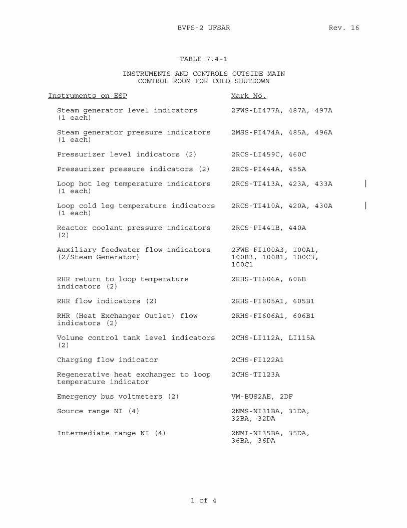
BVPS-2 UFSAR Rev. 16
1 of 4
TABLE 7.4-1
INSTRUMENTS AND CONTROLS OUTSIDE MAIN
CONTROL ROOM FOR COLD SHUTDOWN Instruments on ESP Mark No.
Steam generator level indicators (1 each)
2FWS-LI477A, 487A, 497A
Steam generator pressure indicators (1 each)
2MSS-PI474A, 485A, 496A
Pressurizer level indicators (2) 2RCS-LI459C, 460C Pressurizer pressure indicators (2) 2RCS-PI444A, 455A Loop hot leg temperature indicators (1 each)
2RCS-TI413A, 423A, 433A
Loop cold leg temperature indicators (1 each)
2RCS-TI410A, 420A, 430A
Reactor coolant pressure indicators (2)
2RCS-PI441B, 440A
Auxiliary feedwater flow indicators (2/Steam Generator)
2FWE-FI100A3, 100A1, 100B3, 100B1, 100C3, 100C1
RHR return to loop temperature indicators (2)
2RHS-TI606A, 606B
RHR flow indicators (2) 2RHS-FI605A1, 605B1 RHR (Heat Exchanger Outlet) flow indicators (2)
2RHS-FI606A1, 606B1
Volume control tank level indicators (2)
2CHS-LI112A, LI115A
Charging flow indicator 2CHS-FI122A1 Regenerative heat exchanger to loop temperature indicator
2CHS-TI123A
Emergency bus voltmeters (2) VM-BUS2AE, 2DF Source range NI (4) 2NMS-NI31BA, 31DA,
32BA, 32DA Intermediate range NI (4) 2NMI-NI35BA, 35DA,
36BA, 36DA
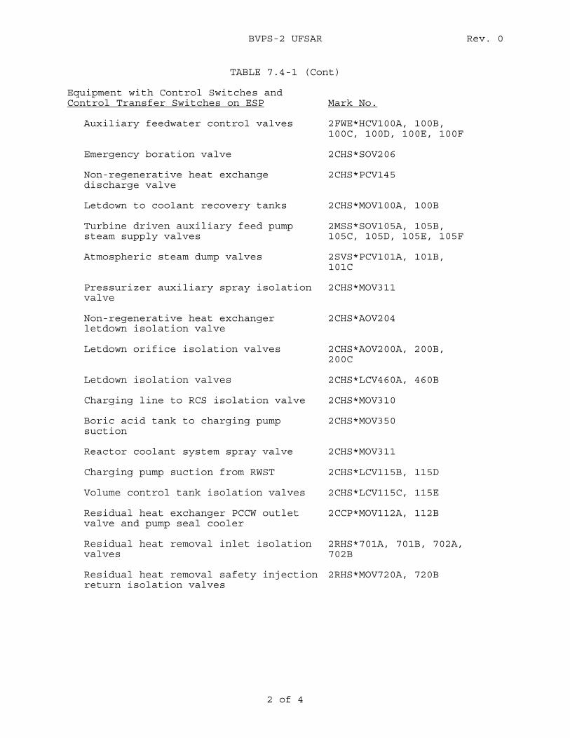
BVPS-2 UFSAR Rev. 0
2 of 4
TABLE 7.4-1 (Cont) Equipment with Control Switches and Control Transfer Switches on ESP
Mark No.
Auxiliary feedwater control valves 2FWE*HCV100A, 100B,
100C, 100D, 100E, 100F Emergency boration valve 2CHS*SOV206 Non-regenerative heat exchange discharge valve
2CHS*PCV145
Letdown to coolant recovery tanks 2CHS*MOV100A, 100B Turbine driven auxiliary feed pump steam supply valves
2MSS*SOV105A, 105B, 105C, 105D, 105E, 105F
Atmospheric steam dump valves 2SVS*PCV101A, 101B,
101C Pressurizer auxiliary spray isolation valve
2CHS*MOV311
Non-regenerative heat exchanger letdown isolation valve
2CHS*AOV204
Letdown orifice isolation valves 2CHS*AOV200A, 200B,
200C Letdown isolation valves 2CHS*LCV460A, 460B Charging line to RCS isolation valve 2CHS*MOV310 Boric acid tank to charging pump suction
2CHS*MOV350
Reactor coolant system spray valve 2CHS*MOV311 Charging pump suction from RWST 2CHS*LCV115B, 115D Volume control tank isolation valves 2CHS*LCV115C, 115E Residual heat exchanger PCCW outlet valve and pump seal cooler
2CCP*MOV112A, 112B
Residual heat removal inlet isolation valves
2RHS*701A, 701B, 702A, 702B
Residual heat removal safety injection return isolation valves
2RHS*MOV720A, 720B
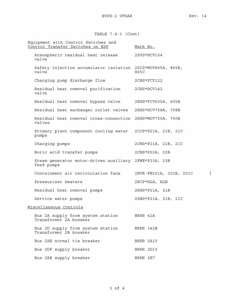
BVPS-2 UFSAR Rev. 14
3 of 4
TABLE 7.4-1 (Cont)
Equipment with Control Switches and Control Transfer Switches on ESP
Mark No.
Atmospheric residual heat release valve
2SVS*HCV104
Safety injection accumulator isolation valve
2SIS*MOV865A, 865B, 865C
Charging pump discharge flow 2CHS*FCV122 Residual heat removal purification valve
2CHS*HCV142
Residual heat removal bypass valve 2RHS*FCV605A, 605B Residual heat exchanger outlet valves 2RHS*HCV758A, 758B Residual heat removal cross-connection valves
2RHS*MOV750A, 750B
Primary plant component cooling water pumps
2CCP*P21A, 21B, 21C
Charging pumps 2CHS*P21A, 21B, 21C Boric acid transfer pumps 2CHS*P22A, 22B Steam generator motor-driven auxiliary feed pumps
2FWE*P23A, 23B
Containment air recirculation fans 2HVR-FN201A, 201B, 201C Pressurizer heaters 2RCP*H2A, H2B Residual heat removal pumps 2RHS*P21A, 21B Service water pumps 2SWS*P21A, 21B, 21C
Miscellaneous Controls
Bus 2A supply from system station Transformer 2A breaker
BRKR 42A
Bus 2D supply from system station Transformer 2B breaker
BRKR 342B
Bus 2AE normal tie breaker BRKR 2A10 Bus 2DF supply breaker BRKR 2D10 Bus 2AE supply breaker BRKR 2E7
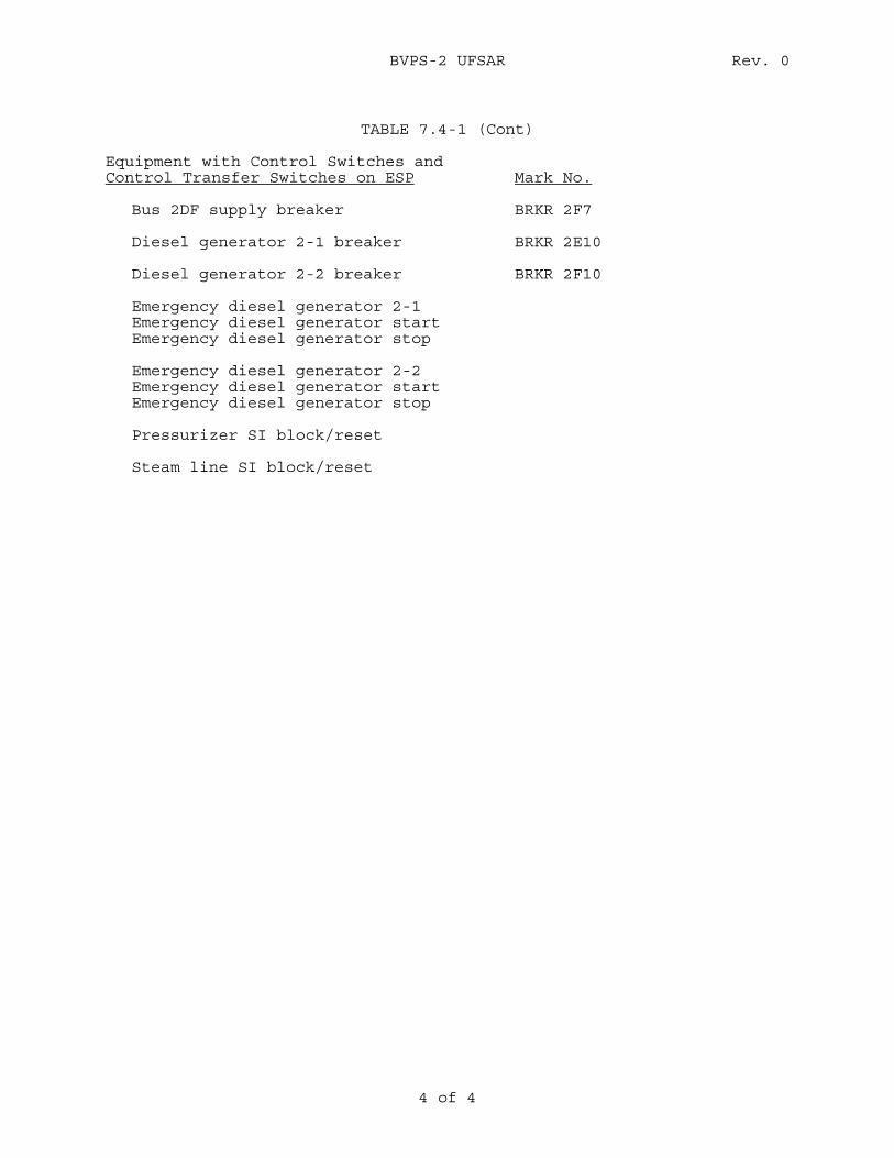
BVPS-2 UFSAR Rev. 0
4 of 4
TABLE 7.4-1 (Cont)
Equipment with Control Switches and Control Transfer Switches on ESP
Mark No.
Bus 2DF supply breaker BRKR 2F7 Diesel generator 2-1 breaker BRKR 2E10 Diesel generator 2-2 breaker BRKR 2F10 Emergency diesel generator 2-1 Emergency diesel generator start Emergency diesel generator stop Emergency diesel generator 2-2 Emergency diesel generator start Emergency diesel generator stop Pressurizer SI block/reset Steam line SI block/reset
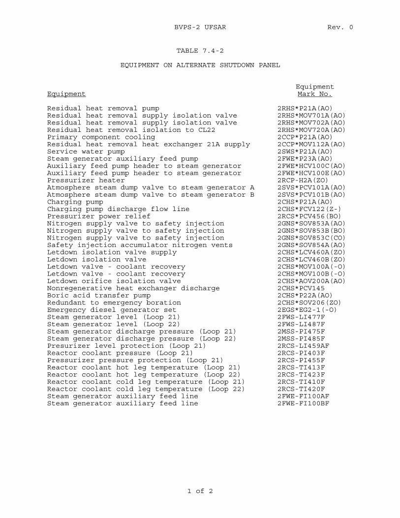
BVPS-2 UFSAR Rev. 0
1 of 2
TABLE 7.4-2
EQUIPMENT ON ALTERNATE SHUTDOWN PANEL Equipment
Equipment Mark No.
Residual heat removal pump 2RHS*P21A(AO) Residual heat removal supply isolation valve 2RHS*MOV701A(AO) Residual heat removal supply isolation valve 2RHS*MOV702A(AO) Residual heat removal isolation to CL22 2RHS*MOV720A(AO) Primary component cooling 2CCP*P21A(AO) Residual heat removal heat exchanger 21A supply 2CCP*MOV112A(AO) Service water pump 2SWS*P21A(AO) Steam generator auxiliary feed pump 2FWE*P23A(AO) Auxiliary feed pump header to steam generator 2FWE*HCV100C(AO) Auxiliary feed pump header to steam generator 2FWE*HCV100E(AO) Pressurizer heater 2RCP-H2A(ZO) Atmosphere steam dump valve to steam generator A 2SVS*PCV101A(AO) Atmosphere steam dump valve to steam generator B 2SVS*PCV101B(AO) Charging pump 2CHS*P21A(AO) Charging pump discharge flow line 2CHS*FCV122(Z-) Pressurizer power relief 2RCS*PCV456(BO) Nitrogen supply valve to safety injection 2GNS*SOV853A(AO) Nitrogen supply valve to safety injection 2GNS*SOV853B(BO) Nitrogen supply valve to safety injection 2GNS*SOV853C(CO) Safety injection accumulator nitrogen vents 2GNS*SOV854A(AO) Letdown isolation valve supply 2CHS*LCV460A(ZO) Letdown isolation valve 2CHS*LCV460B(ZO) Letdown valve - coolant recovery 2CHS*MOV100A(-O) Letdown valve - coolant recovery 2CHS*MOV100B(-O) Letdown orifice isolation valve 2CHS*AOV200A(AO) Nonregenerative heat exchanger discharge 2CHS*PCV145 Boric acid transfer pump 2CHS*P22A(AO) Redundant to emergency boration 2CHS*SOV206(ZO) Emergency diesel generator set 2EGS*EG2-1(-O) Steam generator level (Loop 21) 2FWS-LI477F Steam generator level (Loop 22) 2FWS-LI487F Steam generator discharge pressure (Loop 21) 2MSS-PI475F Steam generator discharge pressure (Loop 22) 2MSS-PI485F Presurizer level protection (Loop 21) 2RCS-LI459AF Reactor coolant pressure (Loop 21) 2RCS-PI403F Pressurizer pressure protection (Loop 21) 2RCS-PI455F Reactor coolant hot leg temperature (Loop 21) 2RCS-TI413F Reactor coolant hot leg temperature (Loop 22) 2RCS-TI423F Reactor coolant cold leg temperature (Loop 21) 2RCS-TI410F Reactor coolant cold leg temperature (Loop 22) 2RCS-TI420F Steam generator auxiliary feed line 2FWE-FI100AF Steam generator auxiliary feed line 2FWE-FI100BF
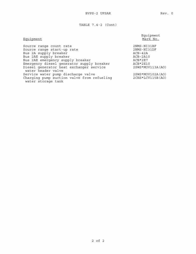
BVPS-2 UFSAR Rev. 0
2 of 2
TABLE 7.4-2 (Cont)
Equipment
Equipment Mark No.
Source range count rate 2NMS-NI31BF Source range start-up rate 2NMS-NI31DF Bus 2A supply breaker ACB-42A Bus 2AE supply breaker ACB-2A10 Bus 2AE emergency supply breaker ACB*2E7 Emergency diesel generator supply breaker ACB*2E10 Diesel generator heat exchanger service 2SWS*MOV113A(AO) water header valve Service water pump discharge valve 2SWS*MOV102A(AO) Charging pump suction valve from refueling 2CHS*LCV115B(AO) water storage tank
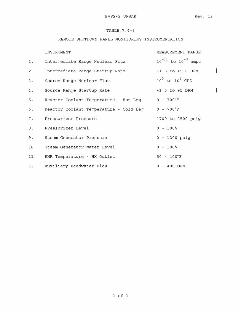
BVPS-2 UFSAR Rev. 13
1 of 1
TABLE 7.4-3
REMOTE SHUTDOWN PANEL MONITORING INSTRUMENTATION INSTRUMENT MEASUREMENT RANGE 1. Intermediate Range Nuclear Flux 10
-11 to 10
-3 amps
2. Intermediate Range Startup Rate -1.5 to +5.0 DPM 3. Source Range Nuclear Flux 10
0 to 10
6 CPS
4. Source Range Startup Rate -1.5 to +5 DPM 5. Reactor Coolant Temperature - Hot Leg 0 - 700°F 6. Reactor Coolant Temperature - Cold Leg 0 - 700°F 7. Pressurizer Pressure 1700 to 2500 psig 8. Pressurizer Level 0 - 100% 9. Steam Generator Pressure 0 - 1200 psig 10. Steam Generator Water Level 0 - 100% 11. RHR Temperature - HX Outlet 50 - 400°F 12. Auxiliary Feedwater Flow 0 - 400 GPM
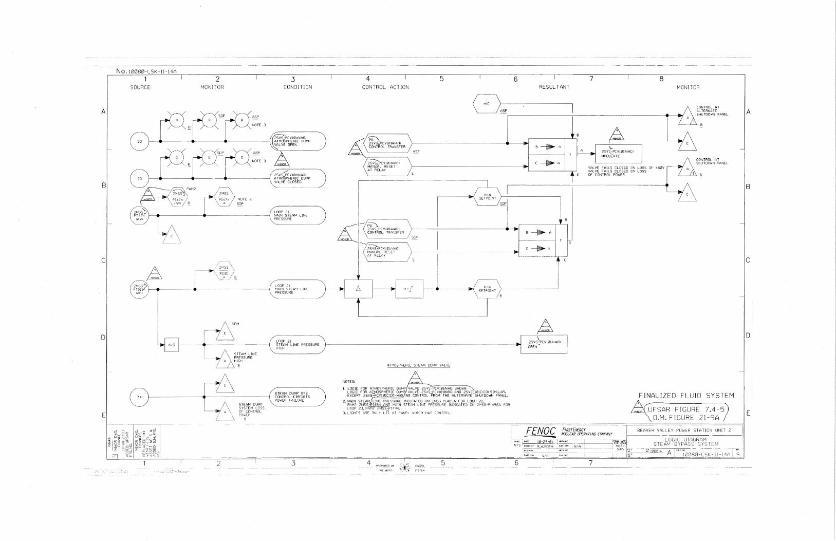
A
L
B
c
D
E
No. t0080-LSK-1H4A
1 SOURCE
l_~/\. / c \
(
2 MONI":OR
/,-~.,
\ \
P[lV'il / \~c::., / §_
2
3 CONDITION
LOOP 21 MAIN S TEAH liNE
\,:RES SURE
·······~ STEA>1 0U>1P SYS CONTROL CIRCUITS POWER FAILURE
3
4 5 CONTROL ACTION
DUMP VALvE:.
NOTES:
1. LOGIC FOR ATMOSPHERIC OUHP VALVE 2SVS-PCVl01A(A0l SHOWN
~~g~~t~~v~~~g~~~l~7~6l g~~R N~Atb~r~b~5~~~0W~~01~~~R~z~~:k0J.S~~~w~IM~~~~l. 2. >1AJN STEA>1 LINE PRESSURE INDICATED ON 2>1SS·PI485A FOR LOOP 22.
PAM2 2MSS-PI484 A!\1[: HA!N STEAM LI~E PRESSURE INDICATED ON 2r~SS-P{4g6A FOR LOOP 23, PAt-12 2MSS_:fi4'H.
3. LIGHTS ARE ONLY LIT ,:,T PAN[!_ 'w'H[CH HAS CnNTRUL.
4 PFlEPAfi£0 f).'l
TNE 8'."?5
5
6 7 RESULTANT
t i
). 2SVS-PCV101A<AOl OPEN-
FENOC ~~( ~10-29-01_
N ' S ~ -~~~--~-~-- __ !3_~_w .R.Q T "1_
f>..l/A
6
·-
HRSTfNERGY NIXLEAR OPERATING COMPANY
8 MC~JITOR
\ CONTROL AT
~~~~~~--~----~~ A SHUTDOWN PANEL AALTERNATE
L B
FINALIZED FLUID SYSTEM
UFSAR FIGURE 7.4--5 O.M. FIGURE 21-9A
BEAVER VALLEY POW~R SlATION UNil i------·-------
LOGIC DIAGRAI"i STEAM BYPASS SYSTEM
A 1808Q-LC'!;-ll-l4(1l 0
A
B
c
D
E
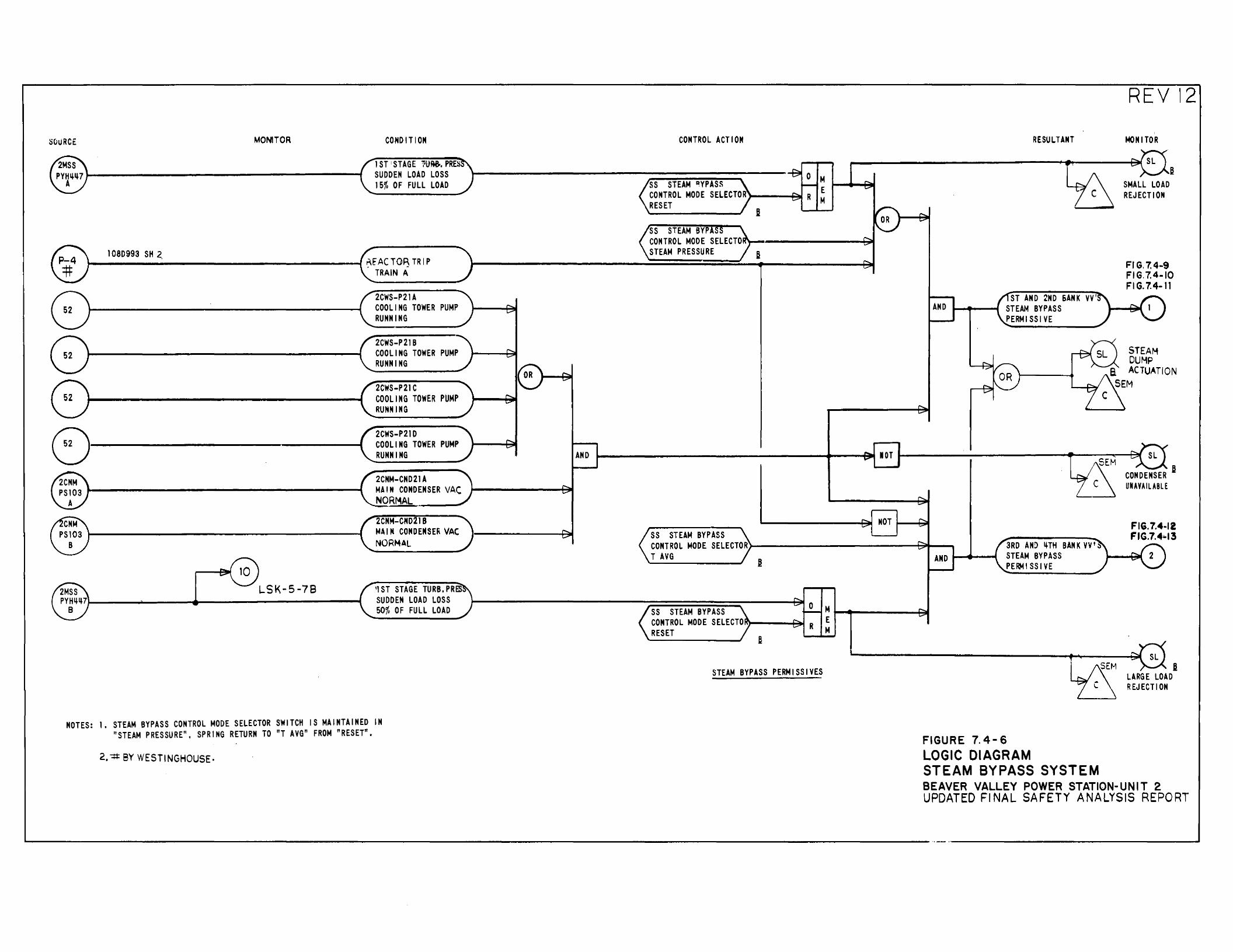
SCILJRCE MONITOR CONDITION
lST 1 STAGE 1V~.PRE~ SUDDEN LOAD LOSS 15% OF FULL LOAD
1 08D993 SH 2. ~E"ACTOR TRIP
TRAIN A
2CWS-P21A COOLING TOWER PUMP RUNNING
2CWS-P21B COOLING TOWER PUMP RUNNING
2CWS-P21C COOLING TOWER PUMP RUNNING
C) 2CWS-P21D COOLING TOWER PUMP RUNNING
2CNM-CND21A MAIN CONDENSER VAC NORMAL
2CNM-CND21B MAIN CONDENSE~ VAC NORMAL
LSK-5-78 11 ST STAGE TURB. PRES SUDDEN LOAD LOSS 50% OF FULL LOAD
NOTES: 1, STEAM BYPASS CONTROL MODE SELECTOR SWITCH IS MAINTAINED IN "STEAM PRESSURE", SPRING RETURN TO "T AVG" FROM "RESET".
2, "#BY WESTINGHOUSE·
CONTROL ACTION
ss STEAM DYPASS M CONTROL MODE SELECTOR E RESET M
I ss STEAM BYP CONTROL MODE SELECTO STEAM PRESSURE I
AND
ss STEAM BYPASS CONTROL MODE SELECTOR T AVG
~
ss STEAM BYPASS CONTROL MODE SELECTO RESET
B
STEAM BYPASS PERMISSIVE$
lOT
NOT
M E M
RESULTANT
ST AND 2ND SANK VV' AND STEAM BYPASS
PERMISSIVE
3RD AN:> 4-TH BANK vv I:)
AND STEAM BYPASS PE~ ISS I VE
FIGURE 7.4-6 LOGIC DIAGRAM STEAM BYPASS SYSTEM
REVI2 I
MONITOR
6 SMALL LOAD REJECTION
Fl G. 7.4-9 FIG.7.4-10 FIG.7.4-11
STEAM DUHP
a ACTUATION SEM
CONDENSER B UNAVAILABLE
A LARGE LOAD REJECT I ON
BEAVER VALLEY POWER STATION-UNIT 2 UPDATED Fl NAL SAFETY ANALYSIS REPORT
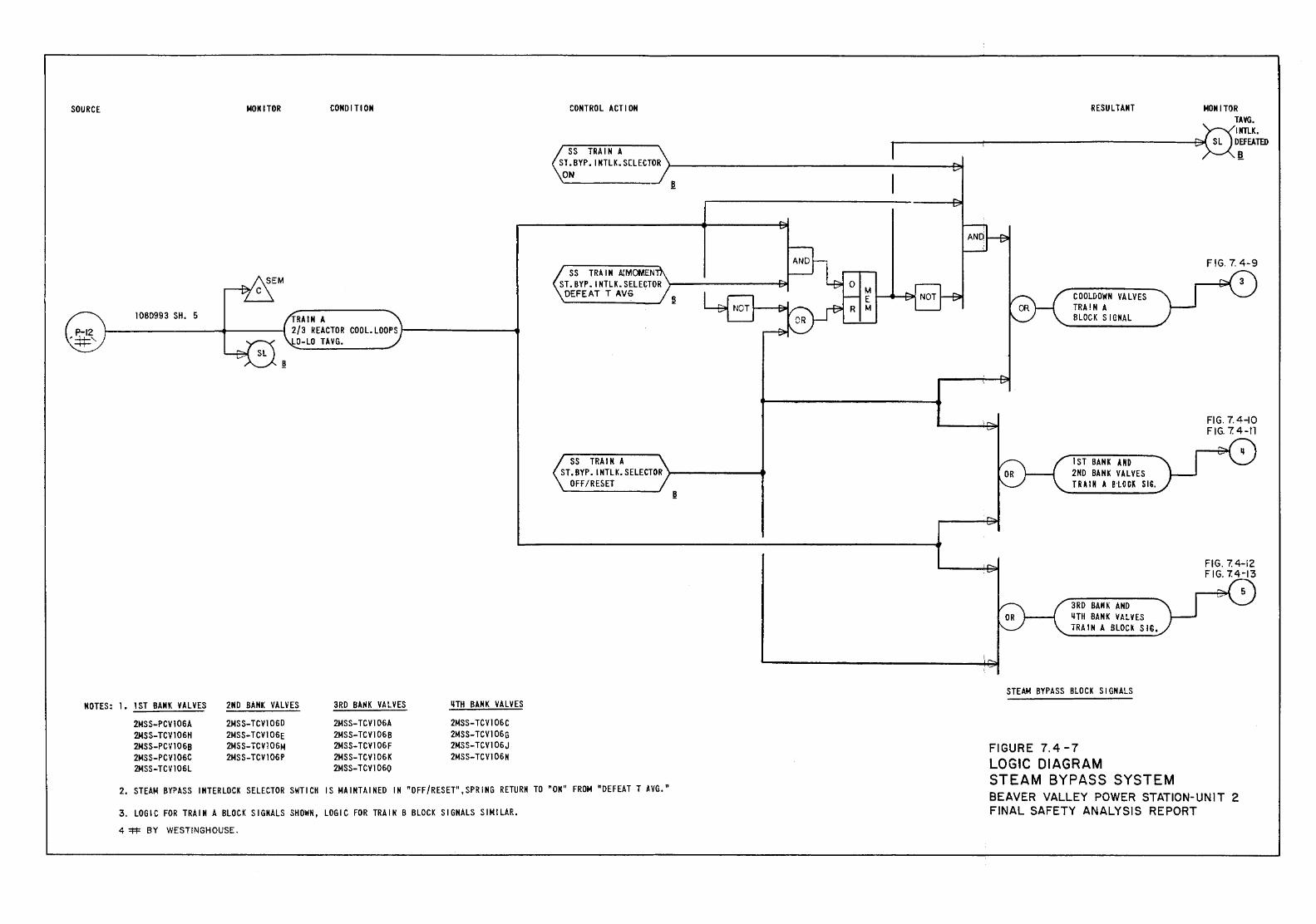
SOURCE MOM I TOR COMO I TIOM
10BD993 SH. 5 TRAIN A 1-----------------+--------1 2/3 REACTOR COOL. LOOPS J----------4
0-LO TAYG.
NOTES: 1. 1ST BANK VALVES 2ND BANK VALVES 3RD BAliK VALVES IHH BANK VALVES
2MSS-PCV106A 2MSS-TCVI 060 2MSS-TCV106A 2MSS-TCV106C 2MSS-TCV106H 2MSS-TCVJ06E 2MSS-TCV106B 2MSS-TCV106G 2MSS-PCYJ06B 2MSS-TCV106M 2MSS-TCV106F 2MSS-TCV106J 2MSS-PCV106C 2MSS-TCV106P 2MSS-TCV106K 2MSS-TCV106N 2MSS-TCV 106L 2MSS-TCV106Q
CONTROL ACTION RESULTANT MONITOR
~~K. r------------------------------------------- SL Dg_ff~TID SS TRAIN A ST. BYP. I KTLK. S[LECTOR J-----------------------------------------+:..1 ON
SS TRAIN ACMOMEN ST.BYP. INTLK.SELECTOR )---------l;,t DEFEAT T AVG
SS TRAIM A ST.BYP.INTLK.SELECTOR >------.......
OFF/RESET .!!
COOLDOWN VALVES TRA!N A BLOCK S I GMAL
I ST BANK AND 2ND BANK VALVES TRAIN A BLOCK SIG .
3RD BANK AND IHH BANK VALVES TRAIN A BLOCK SIG,
STEAM BYPASS BLOCK SIGNALS
FIGURE 7.4-7 LOGIC DIAGRAM STEAM BYPASS SYSTEM
FIG. 7. 4-9
FIG. 7.4-10 FIG. 7.4-ll
FIG. 7. 4-12 FIG. 7.4-13
2. STEAM BYPASS INTERLOCK SELECTOR SWTICH IS MAINTAINED IN "OFF/RESET",SPRING RETURN TO "OK" FROM "DEFEAT T AVG." BEAVER VALLEY POWER STATION-UNIT 2 FINAL SAFETY ANALYSIS REPORT 3. LOGIC FOR TRAIN A BLOCK SIGNALS SHOWN, LOGIC FOR TRAIN B BLOCK SIGNALS SIMILAR.
4 =!=!= BY WESTINGHOUSE.
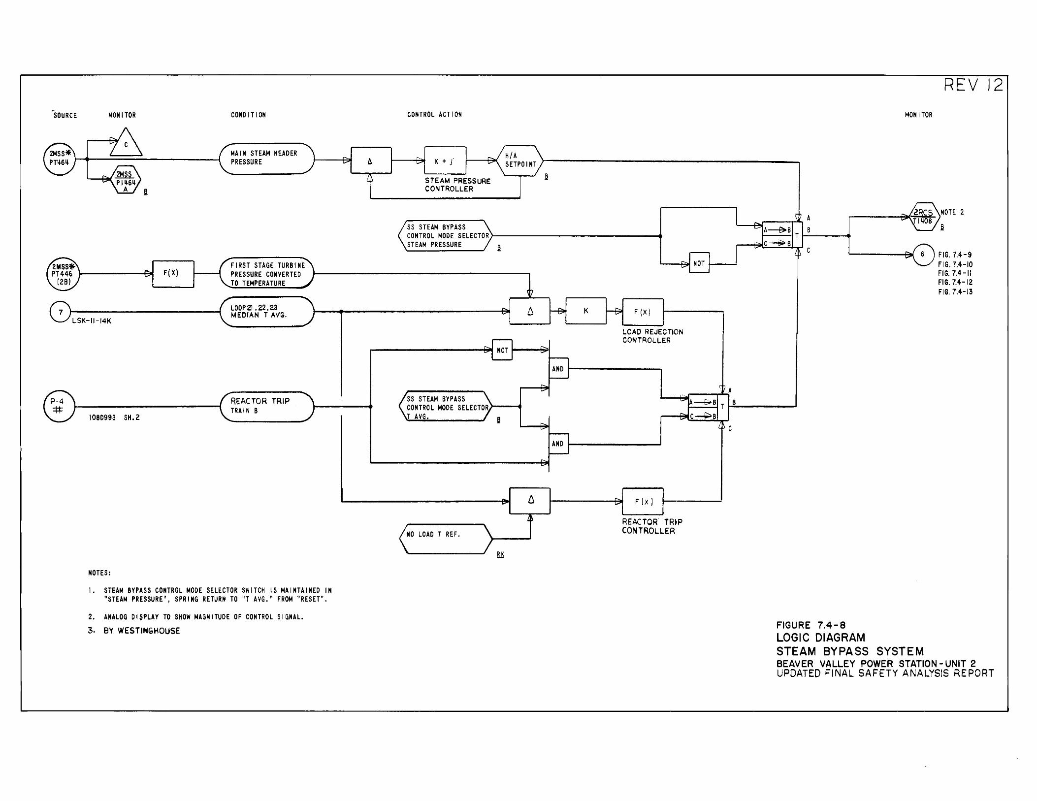
, .. SOURCE MONITOR CONDITION
2MSS* A MAIN STEAM HEADER PH6ij PRESSURE
I'. JMll... """' PIL~6ij
A ~
2MSS* FIRST STAGE TURBINE PT446 ..... F(X) PRESSURE CONVERTED """' ( 28) TO TEMPERATURE
7 LOOP 21 , 22, 23 MEDIAN T I..VG.
LSK-11-14K
® I REACTOR TRIP TRAIt~ B
108D993 SH. 2
NOTES:
I. STEAM BYPASS CONTROL MODE SELECTOR SWITCH IS MAINTAINED IN "STEAM PRESSURE", SPRING RETURN TO "T AVG." FROM "RESET".
2. ANALOG DISPLAY TO SHOW MAGNITUDE OF CONTROL SIGNAL. 3. BY WESTINGHOUSE
CONTROL ACTION
H/A ,...._ 6 r- K + J ......
-.:;;;o" ........ '-"" SETPOINT
L~ STEAM PRESSURE CONTROLLER
SS STEAM BYPASS CONTROL MODE SELECTOR STEAM PRESSURE a
t~
1"'>.. 6 .......
..... NOT ......
SS STEAM BYPASS CONTROL MODE SELECTOR T AVG.
~
~ 6 ... ~~
NO LOAD T REF.
.e
...... NOT ~
~ K ~ F (X)
LOAD REJECTION CONTROLLER
r-... ... AND
,..... ......
' ,_..... A~B
r-... C~B I.' ,...._ ......
AND
r-.. """'
,..._ F !x l """'
REACTOR TR~P CONTROLLER
""" ........
'
\ iJ A
T B
L~ c
\ ? A A--e..B T B C~B
L~ c
FIGURE 7.4-8 LOGIC DIAGRAM
MONITOR
..... 2gc~ I""' Jlij08
.... 6 loo"'
STEAM BYPASS SYSTEM
REV 12
NOTE 2
F F
FIG. 7.4-9 IG. 7.4-10 I G. 7.4 -II
FIG. 7.4-12 FIG. 7.4-13
BEAVER VALLEY POWER STATION- UNIT 2 UPDATED FINAL SAFETY ANALYSIS REPORT
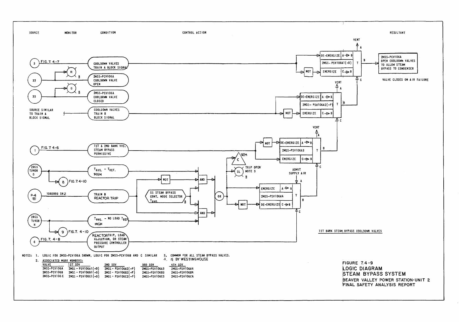
SOURCE NON I TOR
FIG.7. 4-10
108D993 SH 2
CONDIT! OM
TRAIN B REACTOR TRIP
SS STEAM BYPASS CONT. MODE SELECTOR T
CONTROL ACT I OM
TAVG. -NO LOAD TRE p----------------l~ HIGM
FIG. 7. 4-8
NOTES: 1. LOG I C FOR 2MSS-PCV I 06A SHOWN, LOG I C FOR 2MS 5-PCV I 068 AND C SIMI LAR 3. COMNON ~OR All STEAM BYPASS VALVES.
2. ASSOCIATED MARK NUMBERS: VALVE 1ST SOV 2MSS-PCV1 06A 2MS5- PSV1 06A 1 ( -0) 2M SS-PCV 1 068 2MS~ - PS V 1 0681 ( -0) 2MSS-PCV1 06 C 2MSS- PSV 1 06CI { -0)
2ND sov 2MSS- PSV I 06A2{ -P) 2MS~- l'SV 10682{ -P) 2MS5 - PSV I 06C2 ( -P)
4. ~ BY WESTINGHOUSE 3RD SOV 2MSS-PSVI06A3 2MSS-l'S VI 06B3 2MSS-PSV106C3
LITH SOV 2MSS-PSVI06A~
2MSS-PSV106B~ 2MSS-PSV106C~
TRIP OPEN' NOTE 3 ADMIT
SUPPLY A I R
B
c
c
RESULTANT
2MSS-PCV106A OPEN COOLDOWh VALVES
1----t~ TO ALLOW STEAM BYPASS TO CONDENSER
VALVE CLOSES ON AIR FAILURE
I ST BANK STEAM; BYPASS COOLDOwtl VALVES
FIGURE 7.4-9 LOGIC DIAGRAM ~TEAM BYPASS SYSTEM t;!EAVER VALLEY POWER STATION-UNIT 2 IFINAL SAFETY ANALYSIS REPORT
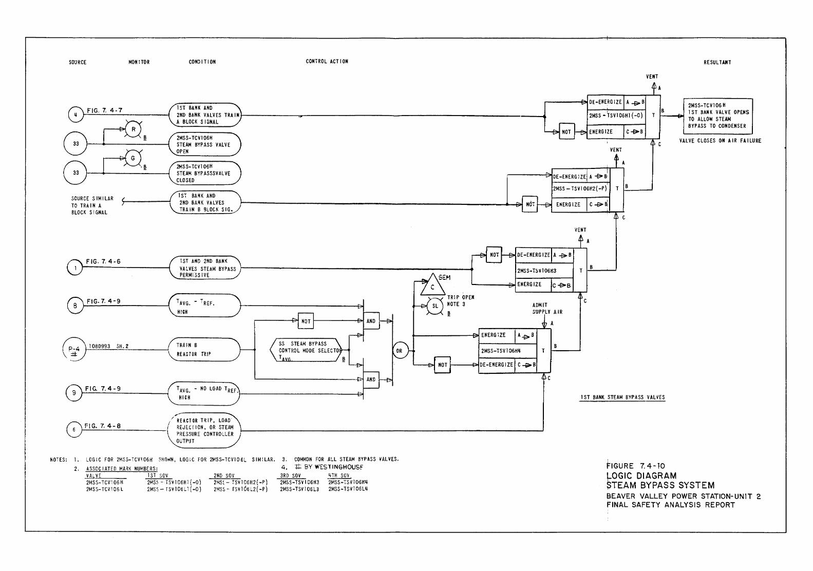
SOURCE MOM !TOR CONDITION CONTROL ACT I ON
1ST BANK AND 2ND BANK VALVES TRAINt-------------~----------------------------------------------------·------4 A BLOCK SIGNAL
SOURCE SIMILAR TO TRAIN A BLOCK SIGNAL
FIG. 7. 4-6
FIG- 7. 4-9
1 OB0993 SH. 2
FIG. 7.4-9
2MSS-TCV106H STEAM BYPASS VALVE OPEN
2MSS-TCVI 06H STEAM BYPASSSVALVE CLOSED
1ST BANK AND 2ND BANK VALVES TRAIN B BLOCK SIG.
1ST AND 2ND BANK VALVES STEAM BYPASS PERMISSIVE
T AVG. - T REF. HIGH
TRAIN B REACTOR TlUP
SS STEAM BYPASS CONTROL MODE SELECTO T
TAVG. - NO LOAD TREF. HIGH J-----------------------------&1
/REACTOR TRIP, LOAD 0 FIG. 7. 4-8 1 REJECIION, OR STEAM ~·---------- PRESSURE CONTROLLER
OUTPUT
NOTES: 1. LOGIC FOR 2MSS-TCV106H SHOWN, LOGIC FOR 2MSS-TCV106L SIMILAR. 2. AS SOC I ATED MARK NUMBERS:
VALVE 2MSS-TGV106H 2MS S-TCVI 06 L
1ST SOV 2MS~- TSV I 06Hl { -0) 2MSS- TSV 106Ll { -0)
21\0 sov 2MS:- TSV106H2{-P) 2MSS- rsv 166 L2 ( -P)
3. COMMON FOR ALL STEAM BYPASS VALVES. 4. 1t BY WESTINGHOUSF 3RD SOV 2MSS-TSV106H3 2MSS-TSVI06L3
liTH SOV 2MSS-TSV106Hll 2MSS-TSV106Lll
TRIP OPEN NOTE 3 ~
2MSS-TSV106H~
ADMIT SUPPLY AIR
A
B T
VENT
VENT
VENT
A
c
A
B
c
RESULTANT
2MSS-TCV106H 1ST BANK VALVE OPEHS TO ALLOW STEAM BYPASS TO CONDENSER
VALVE CLOSES ON AIR FAILURE
1ST BANK STEAM BYPASS VAL~ES
' FIGURE 7.4-10 ~OGIC DIAGRAM ~TEAM BYPASS SYSTEM BEAVER VALLEY POWER STATION-UNIT 2 FINAL SAFETY ANALYSIS REPORT
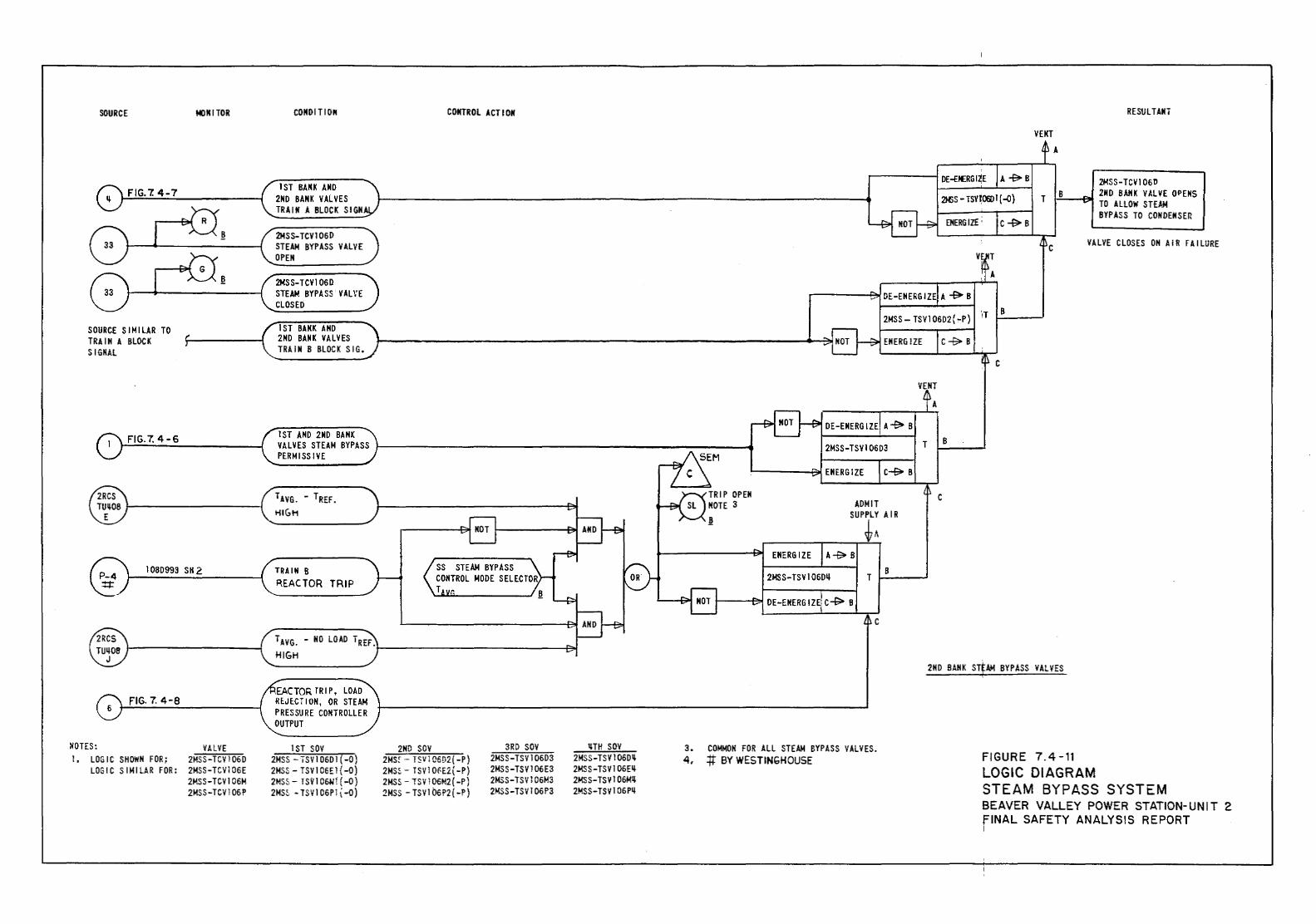
SOURCE
FIG. 7. 4-7
SOURCE SIMILAR TO TRA I H A BLOCK SIGMAL
FIG. 7. 4-6
MONITOR
®RCS T~~OB 1----------1
IOBD993 SH 2
FIG. 7. 4-8
NOTES: VALVE I, LOGIC SHOWN FOR; 2MSS-TCV106D
LOGIC SIMILAR FOR: 2MSS-TCV106E 2MSS-TCV106M 2MSS-TCVl 06P
CONDITION
1ST BANI< AND 2ND BANK VALVES TRAIN A BLOCK SIGH
2MSS-TCV1060 STEAM BYPASS VALVE OPEN
2MSS-TCV1 060 STEAM BYPASS VALVE CLOSED
1ST BANK AND 2ND BANK VALVES TRAIN B BLOCK SIG.
I ST AND 2ND BA HK VALVES STEAM BYPASS PERMISSIVE
......_ _____ _ TRAIN B REACTOR TRIP
CONTROL ACTION
SS STEAM BYPASS CONTROL MODE SELECTOR T
TAVG. - NO LOAD 'iREF. ~------------4~ HIGH
EACTOR TR I P, LOAD REJECTION, OR STEAM PRESSURE CONTROLLER OUTPUT
1ST SOV 2MSS -ISV1 06Dl ( -0) 2MSS- TSV 1 06E1 ( -0) 2MSS - TSV 1 06h'i [ -0) 2MS~ -TSV106Pli-O)
2ND SOY 2M Sf- T5V1 C6D2( -P) 2MSS- TSV 1 O~E2.( -P) 2MSS- TSV 106M2( -P) 2MSS - TSV 1 06P2 ( -P)
3RD SOY 2MSS-TSV106D3 2MSS-TSVl 06E3 2MSS-TSV106M3 2MSS-TSV 1 06P3
llTH SOY 2MSS-TSV106Dil 2MSS-TSV106Eil 2MSS-TSVI06Mil 2MSS-TSV106Pil
ADMIT SUPPLY AIR
~A
T B
c
3. COMMON FOR ALL STEAM BYPASS VALVES. 4, .ft BY WESTINGHOUSE
DE-ENERGIZE
VENT A
RESULTANT
2MSS-TCV106D 2MSS - TSV~OOJ I ( -0) T J..!B:..._-AII 2ND BANK VALVE OPENS
TO ALLOW STE.A.M BYPASS TO CONDENSER
c VALVE CLOSES ON AIR FAILURE
B
2ND BANK STfAM BYPASS VALVES
FIGURE 7.4-11 LOGIC DIAGRAM STEAM BYPASS SYSTEM BEAVER VALLEY POWER STATION-UNIT 2 fiNAL SAFETY ANALYSIS REPORT I
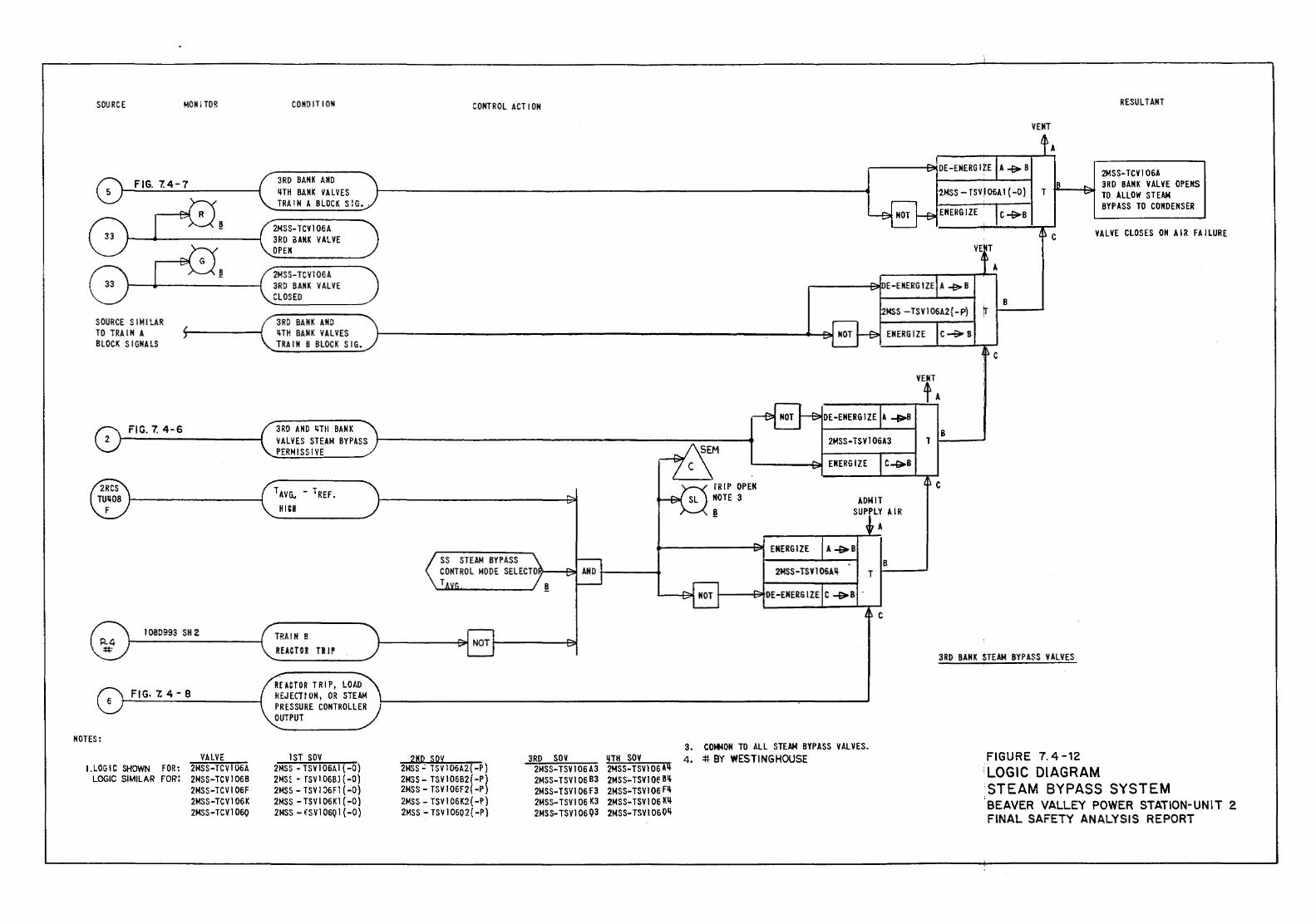
SOURCE MONJTO~
FIG. 7.4-7
SOURCE S l MILAR TO TRAIN A BLOCK SIGNALS
FIG. 7. 4-6 2
IOBD993 SH 2
FIG-7.4-8
NOTES:
!.LOGIC SHOWN FOR: LOGIC SIMILAR FOR:
VALVE 2MSS-TCVI06A 2MSS-TCV106B 2MSS-TCVI 06F 2MSS-TCV106K 2MSS-TCVI06Q
COHO IT I ON
3RO BANK AND LITH BANK VALVES TRAIN A BLOCK SiG •.
2MSS-TCV 1 06 A 3RO oANK VALVE OPEN
2MSS-TCV1 06A 3RD BANK VALVE CLOSED
3RO BANK AND LITH BANK VALVES TRAIN B BLOCK SIG.
3RO AND LITH BANK VALVES STEAM BYPASS PERMISSIVE
TP.A!N B REACTGR Til J P
REACTOR TRIP, LOAD REJECltON, OR STEAM PRESSURE CONTROLLER OUTPUT
1ST SOY 2MSS - TSV 1 06A 1 ( -0} 2MS~ - rsv1 06BJ ( -o) 2MSS - TSV 1 :>6F1 ( -0) 2MSS - TSVI 06Kl ( ~0) 2MSS- !SV 1 06Q 1 ( -0}
CONTROL ACT I ON
SS STEAM BYPASS CONTROL MODE SELECTOI?.---'::..1 T
2ND SOV 2MSS- TSV 1 06A2( -P} 2MSS- TSY106B2(-P} 2MSS- TSV106F2(-P} 2MSS- TSV 1 06K2( -P) 2MSS -TSV106Q2{-P)
3RD SOY 2MSS-TSVl 06 A3 2MSS-TSV 1 06 B3 2MSS-TSVI 06 F3 2MSS-TSV I 06 K3 2MSS-TSVI 06 Q3
IJTH SOY 2MSS-TSVI 06 All 2MS S-TSV 1 Of 811 2MSS-TSVl 06 Fll 2MSS-TSV1 06 Kll 2MSS-TSVI 060ll
rR IP OPEN NOTE 3
.!!c
ADMIT SUPPLY AIR
A
B T
c
3. COMMON TO ALL STEAM BYPASS VALVES. 4 • .:l:f. BY WESTINGHOUSE
VENT
A
c
B
B
RESULTANT
2MSS-TCV1 06A 3RO BANK VALVE OPENS TO ALLOW STEAM BYPASS TO CONDENSER
VALVE CLOSES ON AI~ FAILURE
T 1---_,
c
3RD BANK STEAM BYPASS VALVES
FIGURE 7. 4-12 'LOGIC DIAGRAM STEAM BYPASS SYSTEM BEAVER VALLEY POWER STATION-UNIT 2 FINAL SAFETY ANALYSIS REPORT
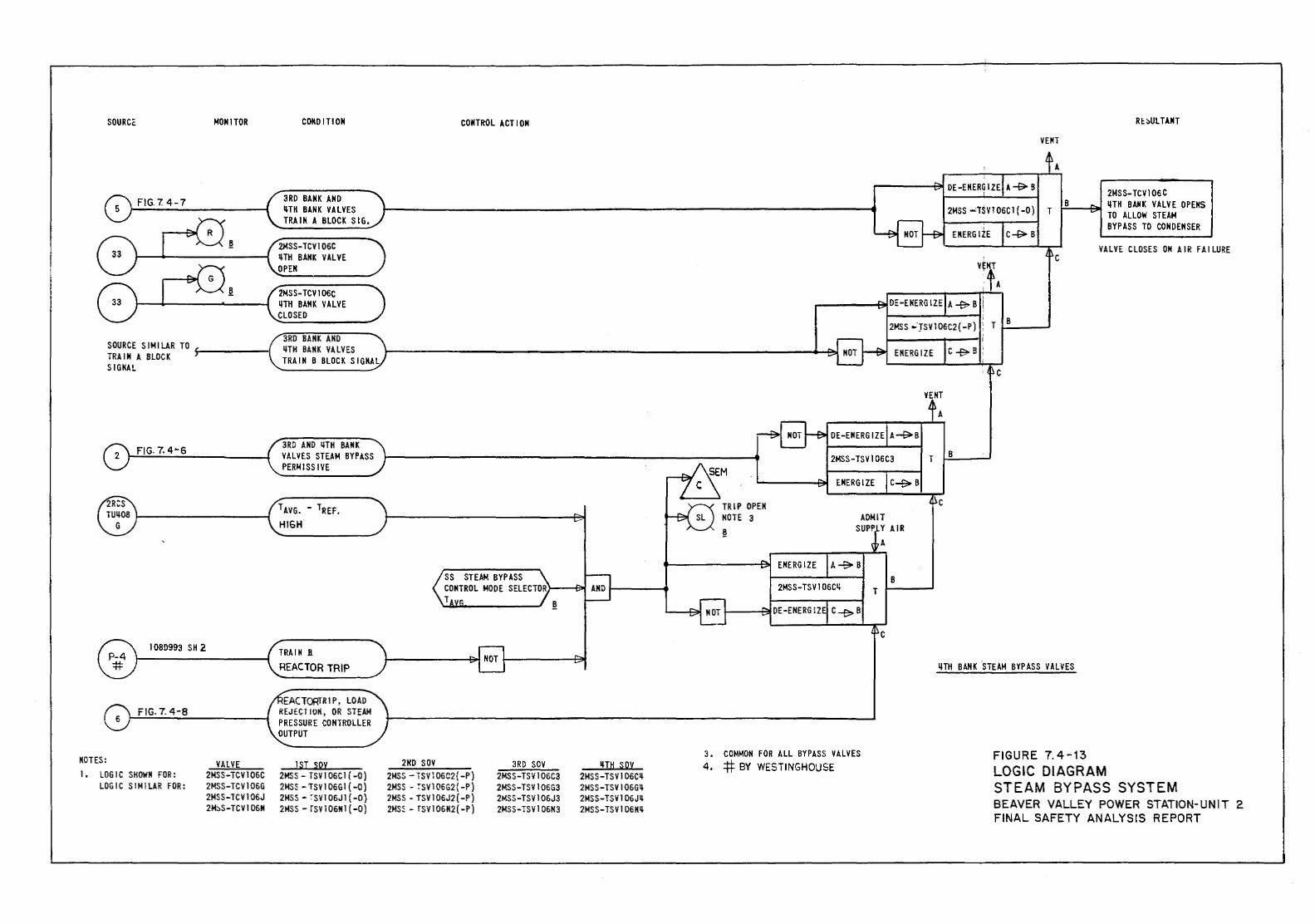
SOURCe MONITOR
FIG. 7. 4-7
SOURCE SIMILAR TO ~-----I TRAIN A BLOCK SIGNAL
FIG. 7. 4-6
10SD993 SH 2
FIG. 7. 4-8
NOTES: 1. LOGIC SHOWN FOR:
LOGIC SIMILAR FOR:
VALVE 2MSS-TCV106C 2MSS-TCV106G 2MSS-TCV 1 06J 2M:,S-TCV106N
CONDITION
3RD BANK AND ltTH BANK VALVES TRAIN A BLOCK SIG.
2MSS-TCV106C 11-TH SANK VALVE OPEN
2MSS-TCV106C ltTH BANK VALVE CLOSED
3RO BANK AND LITH BANK VALVES TRAIN 8 BLOCK SIGNAl
3RD AND LITH BANK VALVES STEAM BYPASS PERiollSSIVE
1 AVG. - 1REF. HIGH
TRAIN B.
REACTOR TRIP
EACT~RlP, LOAD REJECTION, OR STEAM PRESSURE CONTROLLER OUTPUT
lSI soy 2MSS- TSVl 06Cl ( -0) 2MS5 -TSV106G1 ( -0) 2MSS - ~SVl 06Jl ( -0) 2MSS- [SV106Nl ( -0)
CONTROL ACTION
SS STEAM BYPASS CONTROL MODE SELECTOR>----f~ T
2ND SOV 2MSS - TSVl 06C2{ -P) 2MSS - :-svl 06G2 ( -P) 2MSS - TSV 1 06J2 ( -P) 2MSS- fSV106N2{-P)
3RD SOV 2MSS-TSV106C3 2MSS-TSV106G3 2MSS-TSV106J3 2MSS-TSV106N3
LITH SOY 2MSS-TSV106CII-2MSS-TSV106GL! 2MSS-TSV106JL! 2MSS-TSV106Klt
TRIP OPEN NOTE 3
3. COMMON FOR ALL BYPASS VALVES 4. #-BY WESTINGHOUSE
c
B
VEIH
A
c
B
c
R~~ULTANT
2MSS-TCVl 06 C I-'S'--"""""""'~ ltTH SANK VALVE OPEitS
TO ALLOW STEAM BYPASS TO CONDENSER
VALVE CLOSES ON AIR FAILURE
LITH BANK 'sTEAM BYPASS VALVES
FIGURE 7.4-13 LOGIC DIAGRAM STEAM BYPASS SYSTEM BEAVER VALLEY POWER STATION-UNIT 2 FINAL SAFETY ANALYSIS REPORT
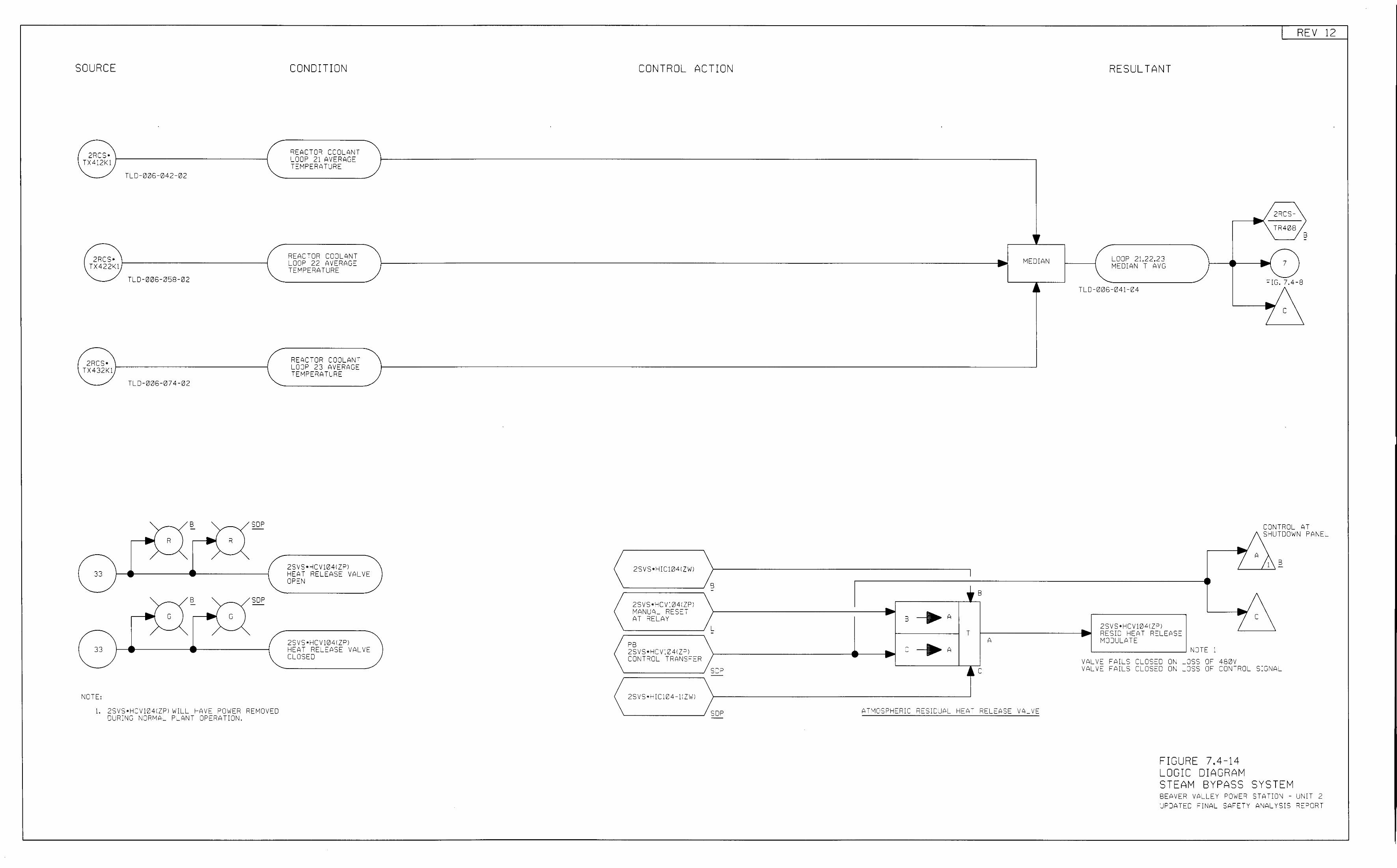
SOURCE
2RCS• TX4:2k1
TL0-006-042-02
2RCS• TX422k1
TLD-006-058-02
2RCS• TX432K1
TL0-0;:)6-074-02
SOP
SOP
t\OTE:
l. 2SVS•HCVliJ41ZPI 1-IILL l-AVE POWE'i REMOVED DURING ~ORMAL PLA~T OPERATION.
CONDITION
REACTOR COOLANT LOOP 21 AVERAGE TEMPERATURE
REACTOR CCOLI'>NT LOOP 22 AVERAGE TEMPERATURE
REACTOR COOLANT LOOP 23 AVERAGE TEMPERATLRE
2SVS•HCV1e41ZPI HEAT RELEASE VALVE OPEN
2SVS•HCV1041ZPI HEAT RELEASE VALVE CLOSED
CONTROL ACTION
2SVS•HIC1041ZWI
::==========~ B 2SVS•HCV:04:ZPI "1ANUAL RESET AT 'iELAY
::==========~ L PB 2SVS•HCV 10 41ZP I CJ~T'iCL TRANSFER
::::::==========::::: s 0 p
2SVS •H IC; 0 4-11 ZWI
'------------..J SOP
, r .. MEDIAN -
~ ~
B
B ___.A T
A C __.A
ATMOSPHERIC RESIDUAL HEAT RELEASE VALVE
RESULTANT
LOOP 21,22,23 MEDIAN T AVG
TLC-006-041-04
2SVS•HCV1041ZPI RESID HEAT RELEASE MODULATE
'----------___J NOTE 1 VALV~ FAILS CLCSEC 0~ LCSS OF 480V
REV 12
... /zRcs-
.,.. \TR408 B
c
-
.. 7 .... FIG. 7.4-8 .. 7 c
CCNTROL AT SI-UTOOWN PANEL
VALV~ FAILS CLCSEC 0~ LCSS OF CONTROL SIGNAL
FIGURE 7.4-14 LOGIC DIAGRAM STEAM BYPASS SYSTEM BEAVER VALLEY POWER STATION - UN:T 2 UPDATED FINAL SAFE-Y ANALYSIS REPORT
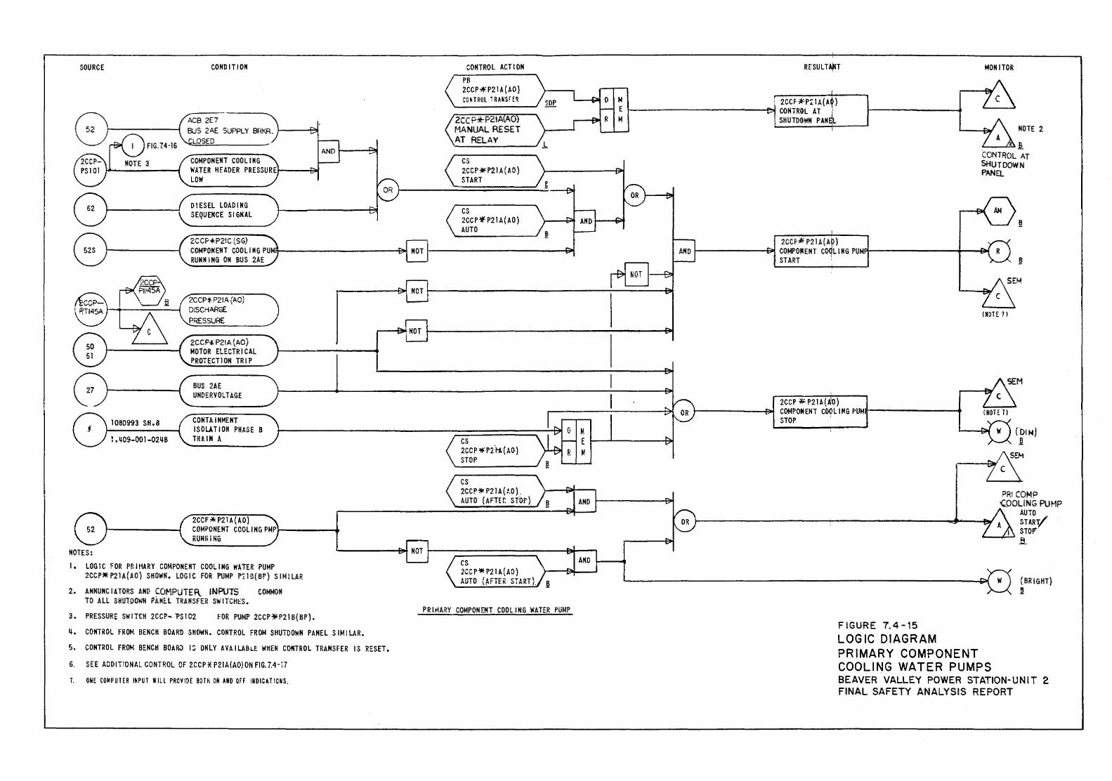
SOURCE
1 080993 Sit. 8
1.~09-001-02~B
NOTES:
CONDITION
COMPONENT COOLING WATER HEADER PRESSURE LOW
DIESEL LOADING SEQUENCE SIGNAL
2CCP*P21C (SG) COMPONENT COOLING PUM RUNNING ON BUS 2AE
2CCP~ P21A (AD} DISCHARGE PRESSURE
2CCP-t P21 A {AD) MOTOR ELECTRICAL PROTECTION TRIP
BUS 2AE UNOERVOLTAGE
CONTAINMENT ISOLATION PHASE B TR.UNA
2CCP'* P21A (AD) COMPONENT COOLING PMP}----_. RUNii I NG
1, LOGIC FOR PR HIARY COMPONENT COOLING WATER PUMP 2CCP*P21A(AO) SHOWN. LOGIC FOR PUMP P!Hl(B!') SIMILAR
2. A NNUNC I A TORS AND COMPUTE F\. INPUTS COMMON TO ALL SHUTDOWN PANEL TRANSFER SWITCHES.
~. PRESSURE SWIT£11 2CCP- ?S102 FOR PUMP 2CCP~P21B(BP).
~. CONTROL FROM BENCH BOARD SHOWN. CONTROL FROM SHUTDOWN PANEL SIMILAR.
5. CONTROL FROM BENCH BDARJ 13 ONLY AVAILABL~ WHEN CONTROL TRANSFER IS RESET.
6. SEE ADDITIONAL CONTROL OF 2CCP *P21A(AO) ON FIG. 7.4-17
1. ONE CO~ PUT ER INPUT WILL PROVIDE BOTH ON AND Off INO I CAll 0 MS.
CONTROL ACTION
PB 2CCP*P21 A (AO} CONTROL TRANS r ER
2CCP*P21A 0 MANUAL RESET AT RELAY
cs 2CCP-:H21 A (AD} START
cs 2CCP * P21 A (AD) AUTO
cs 2CCP ·'lHz"HI(AO) STOP
cs 2CC P '* P21A (.t.O) . AUTO (AFT£r. STOP}
cs 2CCP'* P21 A (AO} AUTO (~FTER START). I!
PRI~ARY COMPONENT CODLING WATER PUMP
ANO ;..---...
RESULT~T MONITOR
I 2CCF k-P.: IA(AO} CONTROL AT ', SHUTDOWN PAN~L
I NOTE 2
.a CONTROL AT SHUTDOWN
2CCF# P21 A(A~) COMPOM ENT coqu N G PUM START
2CCP #P21A(IIO) COMPONENT COOL 1 NG PUMill----------1 STOP
FIGURE 7.4-15
PANR
!HOTE 1 I
LOGIC DIAGRAM PRIMARY COMPONENT COOLING WATER PUMPS
ft
I!
(BRIGHT) I!
BEAVER VALLEY POWER STATION-UNIT 2 FINAL SAFETY ANALYSIS REPORT
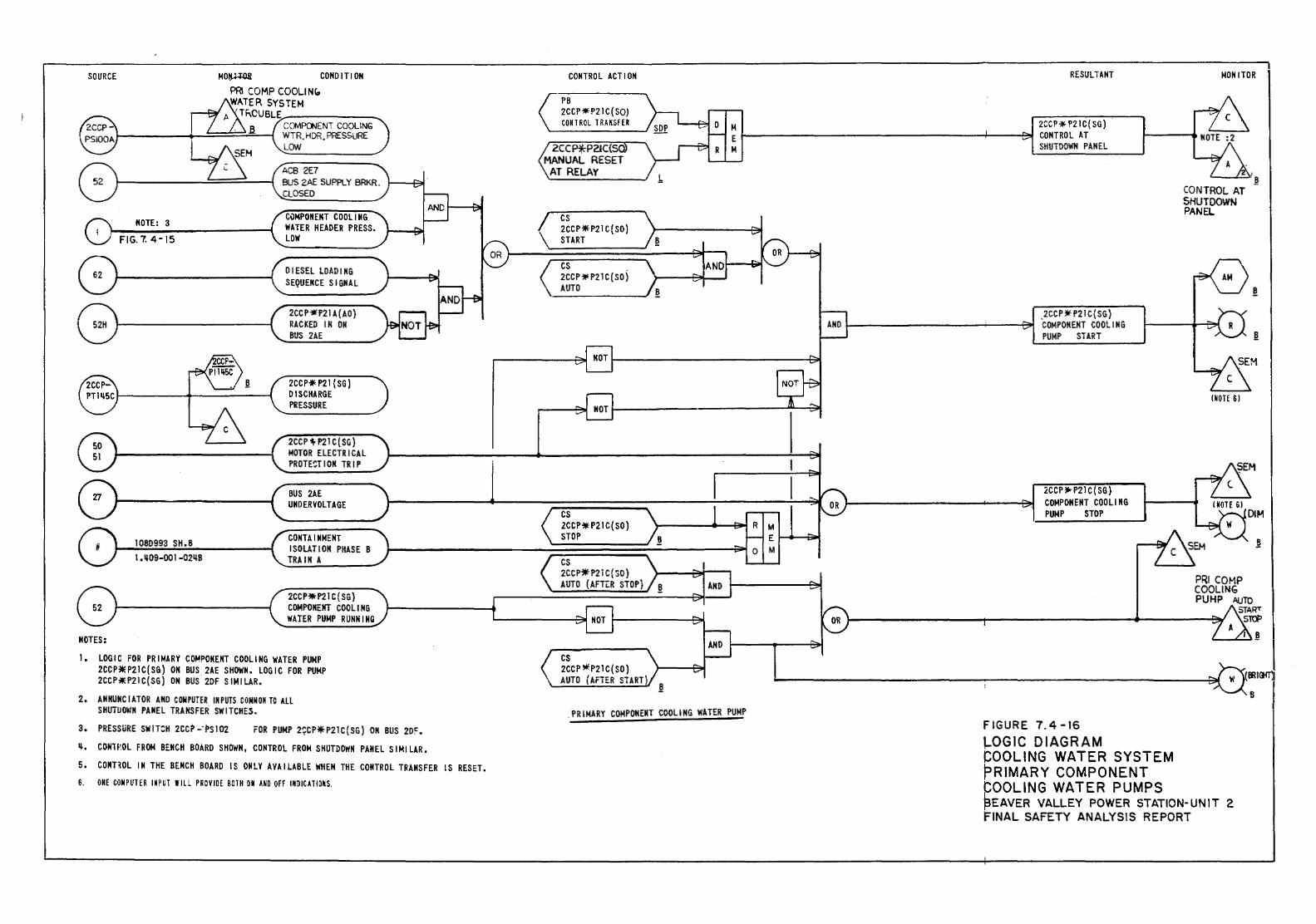
SOURCE MO!U+QJ! CONDITION
p
NOTE: 3
FIG. 7. 4-15
1080993 SH.B l.ll09-001-024-B
NOTES:
PRI COMP COOLINr., WATER SYSTEM
TRCUBLE
.B. COMPOOENT COOLING WTR. HDR. PRESSURE LON
ACB 2E7 BUS 2AE SUPPLY BRKR. CLOSED
CuMPONENT COOLING WATER HEADER PRESS. LOW
DIESEL LOADING SEQUENCE SIGNAL
2CCP*'P21 A(AO) RACKED IN ON BUS 2AE
2CCP*P21(SG) DISCHARGE PRESSURE
2CCP 'H21 C ( SG) MOTOR ELECTRICAL PROTECTION TRIP
BUS 2AE UNDERVOLTAGE
CONTAINMENT ISOLATION PHASE B
TRAIN A
2CCP*P21 C ( SG) COMPONENT COOLING WATER PUMP RUNNING
I. LOGIC FOR PRIMARY COMPONENT COOLING WATER PUNP 2CCP~P21C(SG) ON BUS 2AE SHOWN. LOGIC FOR PUMP 2CCP~P21C(SG) ON BUS 2DF SIMILAR.
2. ANNUNCIATOR AND COMPUTER IN PUTS CONN ONTO All SHUTUOWN PANEL TRANSFER SWITCHES.
3. PRESSURE SWITCH 2CCP -·f>s 102 FOR PUMP 2~CP*P21C(SG) ON BUS 2D~. ll. CONWOL FROM BENCH BOARD SHOWN, CONTROL FROM SHUTDOWK PANEL S I M I LAR. 5. CONT~OL IN THE BENCH BOARD IS ONLY AVAILABLE WHEN THE CONTROL TRANSFER IS RESET. 6. ONE CON P UTE R IN P U! WILL PROVIDE BOTH o• HO Off IMD ICATI OKS.
CONTROL ACTION
PB 2CCP *P21 C (SO) CONTROL T RA NSFE R
2CCP*P21C(S MANUAL RESET
AT RELAY
cs 2CCP* P21 C (SO) START
cs 2CCP ~ P21 C (SO) AUTO
cs lCCP* P21 C( SO) STOP
cs 2CCP*P2 i C{SO) AUTO (AFTLR STOPj
cs 2CCP *'P21 C( SO) AUTO (AfTER START
.PRIMARY COMPONENT COOLING WATER PUMP
RESULTANT
2CCP* P21 C ( SG) CONTROL AT SHUTDOWN PANEL
_2CCP * P21 C( SG) COMPONENT COOLING PUMP START
2CCP .-P21 C( SG) COMPONENT COOLING PUMP STOP
FIGURE 7.4-16 '-OGIC DIAGRAM COOLING WATER SYSTEM PRIMARY COMPONENT ~OOLING WATER PUMPS
MONITOR
/.!! CONTROL AT SHUTDOWN PANEL
~
.!!
PRI COKP COOLING PUHP AUTO
START Sl'CP
'---t.:...:..l.!!
~EAVER VALLEY POWER STATION-UNIT 2 rlNAL SAFETY ANALYSIS REPORT
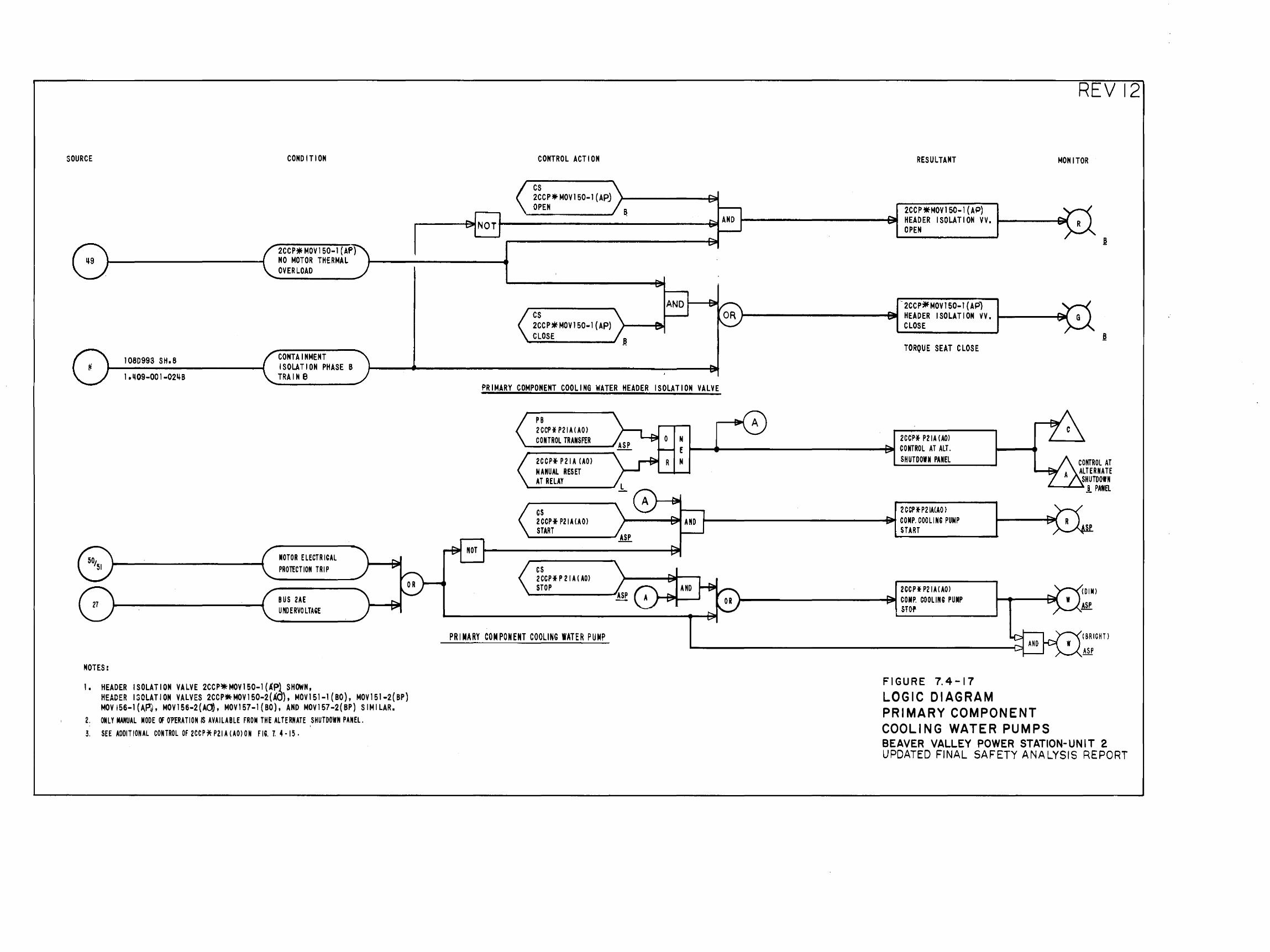
SOURCE
1080993 SH.B
COND I Tl ON
2CCP*MOVI50-1 (AP) NO MOTOR THERMAL OVERLOAD
CONTAINMENT ISOLATION PHASE B TRAIN B
NOTES:
1. HEADER ISOLATION VALVE 2CCP*MOV150-l(.I:P} SHOWN, HEADER ISOLATION VALVES 2CCP~MOVI50-2(AO}, MOV151-1 (BO), MOVI51-2(BP} MOVI56-1(Af'4, MOV156·2(AO), MOVI57-1{BO), AND MOVI57-2{BP) SIMILAR.
2. ONLY MANUAL MODE OF Ol'ERATION IS AVAilABLE FROM THE AlTERNATE ,SHUTDOWN PANEL. 3. SEE ADDITIONAL CONTROL OF 2CCP*P21A(A0)0N FIG. T. 4·15.
CONTROL ACTION
cs 2CCP* MOV150-1 (APJ OPEN
cs 2CCP*MOV150-I (AP) CLOSE
PRIMARY COMPONENT COOLING WATER HEADER ISOLATION VALVE
REVI2
RESULTANT MONITOR
2CCP*MOV150-1 (AP) HEADER ISOLATION VV. ~---.........f!iilll OPEN
-2CCP7if MOV 150-1 ( APl )-----------~ HEADER ISOLATION VV. 1----~ilf
CLOSE
TORQUE SEAT CLOSE
FIGURE 7. 4- I 7 LOGIC DIAGRAM PRIMARY COMPONENT COOLING WATER PUMPS BEAVER VALLEY POWER STATION- UNIT 2 UPDATED FINAL SAFETY ANA LYSIS REPORT
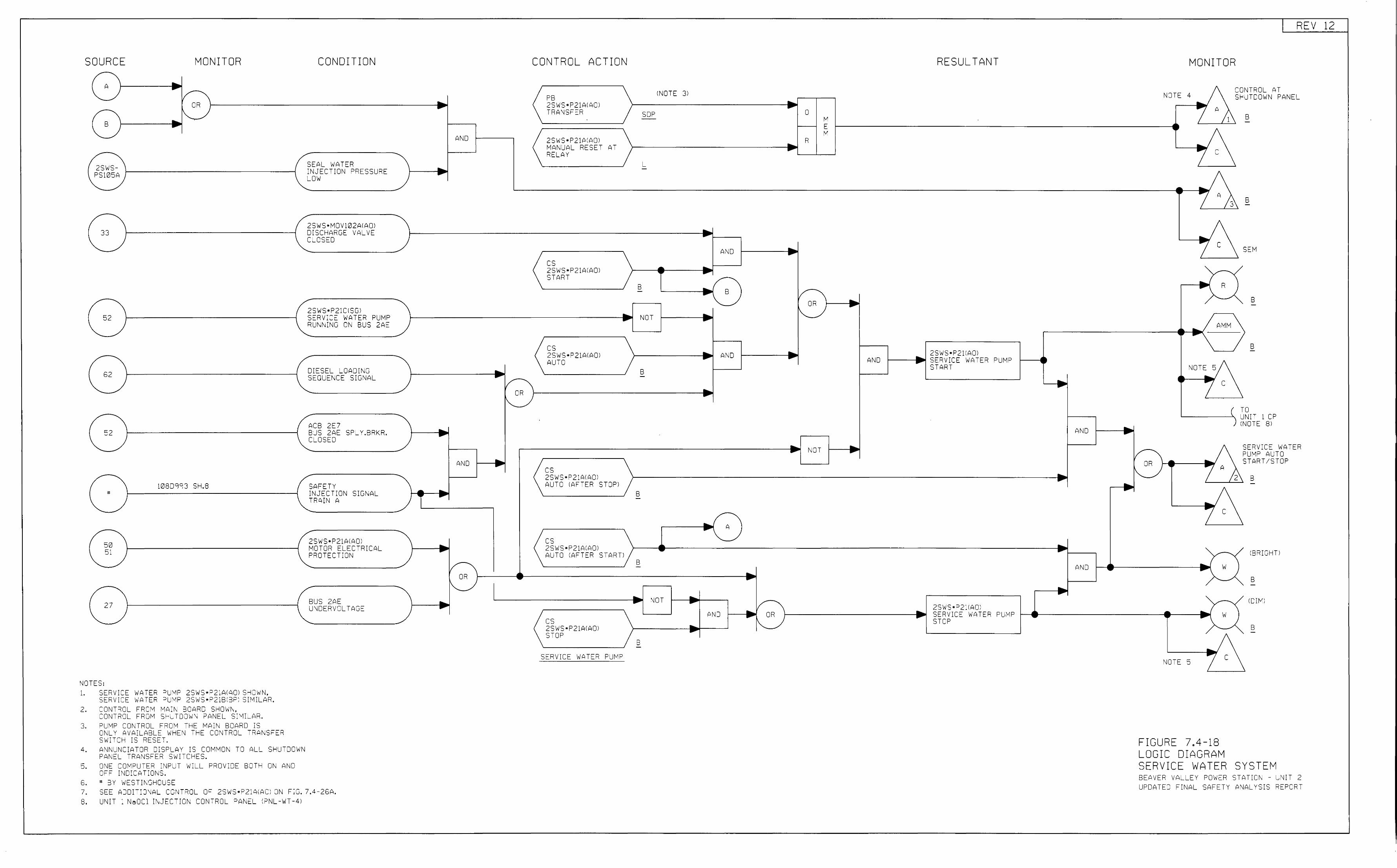
SOURCE
A
2SWS-PS105A
33
52
62
52
MONITOR
OR
108D=i93 SH.8 "
50 51
27
NOTES: 1. SERVICE WATER PU!v1P 2SWS•P21AIAOl SH0 1riN,
SERVICE viATER PUMP 2SWS•P21BIBP) SIMILAR. 2. CONT=iOL FROM MAIN BOARD SHmm,
CONTROL FROM SI-UH)OWN PANEL SIMILAR. 3. =>LMP COt\ TROL FROM -1-E MA:N BOARD IS
ONLY AVAILABLE WHE\J THE CONTROL TRANSFER Sw'ITCfc IS RESET.
4. ANNUNCIATOR DISPI_AY IS COM'v!ON TO ALL SHUTDOWN PANEL TRANSFER SWITCHES.
5. ONE COMPUTER INPL T 'w'ILL PROVIDE BOTH Ot\ AND OFF !ND:C?>TIONS.
5. " BY WESTJt\::;HOUSE
CONDITION
SEAL WATER INJECTION PRESSURE LOW
2S'w'S•MOV 102AI AOl DISCHARGE VALVE CLOSED
2SWS•P21CISG) SERVICE WATER PUMP RUNN:NG ON BUS 2AE
DIESEL _OAJING SEOLENCE SIGNAL
ACB 2E7 BUS 2AE SPL v .BRKR. CLOSED
SAFETY INJECTION SIG\JAL TRAIN {"
2SWS•P21AI{"Q) MOTOR ELECTRICAL PROTECTION
BUS 2AE Ut\DERVJLTAGE
7. SEE ADOI-:Ot\AL CONTRCL OF 2SWS•P2:AIA0) ON FIG. 7.4-26A. 8. UNIT 1 NaOCl :NJECTION CONTROL PANEL IP'\IL -WT -4)
At\J
• AND
~ .... ....
.... .... 1/-
OR 1"-.
... ...
• /-OR
"-
.. ....
~
CONTROL ACTION
PB 2SWS•P21AIA0) TRANSFER
2SWS•P21AIA0) MANUAL RESET AT RELAY
cs 2SWS•P21AIAOl START
cs 2SWS•P21AIAOl AUTO
cs 2S'w'S • P21AI AOl AUTO !AFTER STOP)
cs 2SWS•P2JA:AQ)
•
AUTO !AFTER START!
cs 2SWS•P21AIAOl STOP
SERVICE WATE=i PUMP
!NOTE 3)
SOP
L
.. B -
NOT
B -
B -
• B -
.... NOT .... ... ....
• B -
RESULTANT
0
R
... .. .... AND ....
• -~ B v-
- OR • • 1"-.
• .... AND • 2SWS•P211AOl .... AND SERVICE 'riATER PUMP ~ START _.
• AND • .... t\OT • ....
.... .... ~
-.. ) A .. ... ....
~ AND • ... .. 1/- 2SWS•P211AQ) .... • AND .... OR SERVICE WATER PUMP ~ I'-._ STOP
REV 12
MONITOR
NOTE 4
c
- R ....
..,/ AMM
.... \ NQTE 5 ....
7 c
/ OR ~ A
" .... 7 c
- w ....
--.( w
-....
NOTE 5 7 c
FIGURE 7.4-18 LOGIC DIAGRAM
CCNTROL AT SHUTDOWN PANEL
B
B
SEM
B
B
( T L
0 NIT 1 CP OTE 8) ) IN
s ? s
2
)
ERV:CE WATER UMP AUTO TART/STOP
B
IB=ii::;HTI
B
(J[M)
B
SERVICE WATER SYSTEM BEAVER VALLEY POWER STATION - LNIT 2 UPDATEC FINAL SAFETY ANALYS:S REPORT
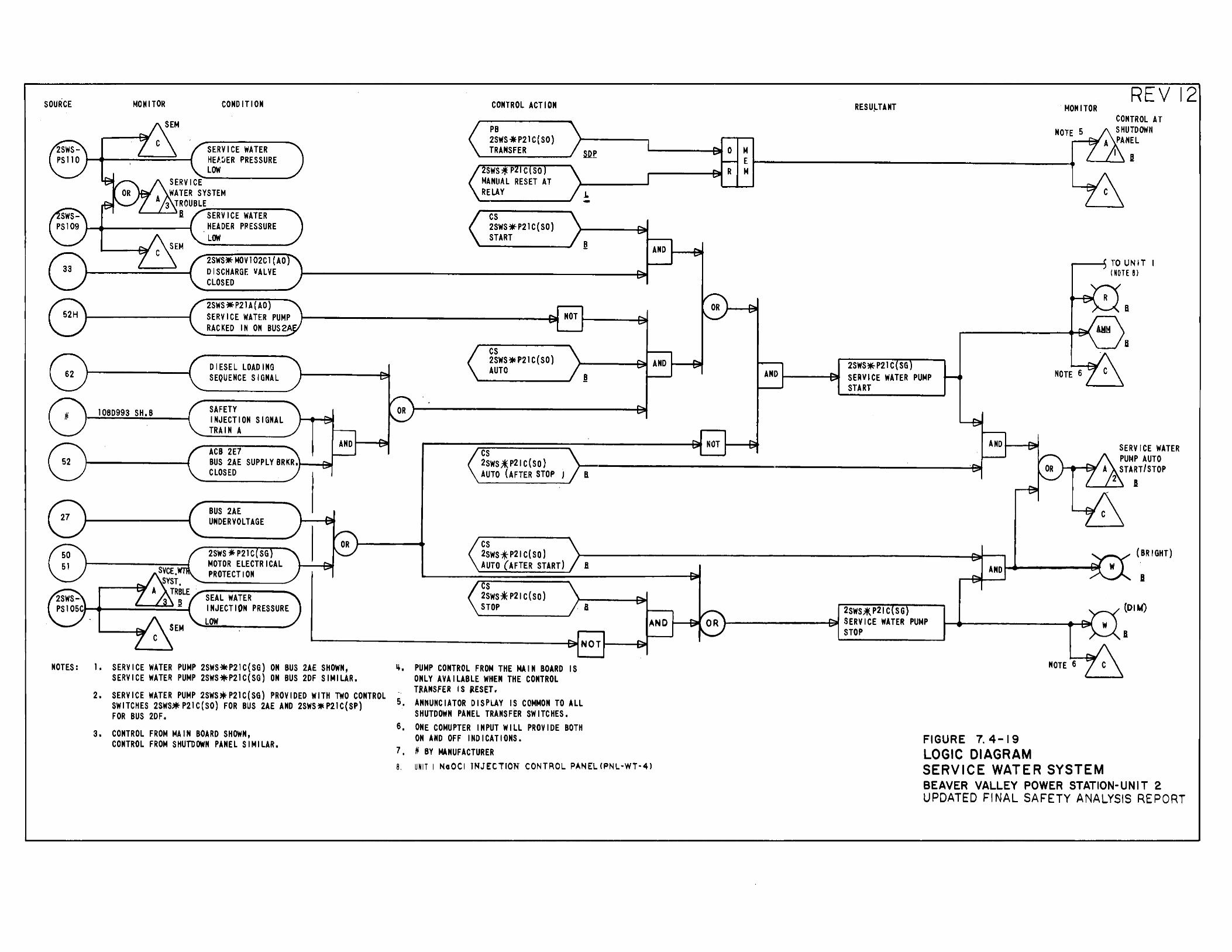
NOTES:
BUS 2AE UNDER VOLTAGE
2SWS * P21 C SG MOTOR ELECTRICAL PROTECTION
SEAL WATER INJECTION PRESSURE
LOW
cs 2SWS-!P21 C(SO) AUTO (AFTER START)
cs 2sws* P21 c (so} STOP
B
~----------------------------------~NOT~--~
1. SERVICE WATER PUMP 2SWS~P21C(SG) ON BUS 2AE SHOWN, SERVICE WATER PUMP 2SWS~P21C(SG) ON BUS 2DF SIMILAR.
ij. PUMP CONTROL FROM THE MAIN BOARD IS ONLY AVAILABLE WHEN THE CONTROL TRANSFER IS RESET. 2. SERVICE WATER PUMP 2SWS)fP21C(SG) PROVIDED WITH TWO CONTROL
SWITCHES 2SWS-*P21C(SO} FOR BUS 2AE AND 2SWS*P21C(SP) 5, ANNUNCIATOR DISPLAY IS COMMON TO ALL FOR BUS 2DF. SHUTDOWN PANEL TRANSFER SWITCHES.
3. CONTROL FROM MAIN BOARD SHOWN, CONTROL FROM SHUTDOWN PANEL SIMILAR.
6, ONE COMUPTER INPUT WILL PROVIDE BOTH ON AND OFF INDICATIONS.
7, ~BY MANUFACTURER 8. UNIT I NaOCI TNJECTTON CONTROL PANEL <PNL·WT·4J
2SWSJIE.P21C SG t----------t~ SERVICE WATER PUMP
STOP
FIGURE 7. 4-19 LOGIC DIAGRAM
NOTE 6
SERVICE WATER SYSTEM
(BRIGHT)
B
(DI t.f)
BEAVER VALLEY POWER STATION-UNIT 2 UPDATED FINAL SAFETY ANALYSIS REPORT
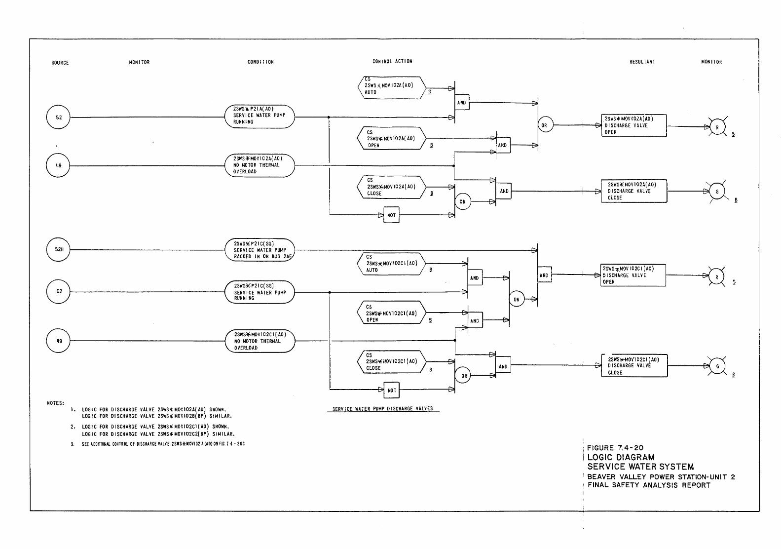
SOURCE MONITOR COHO IT I ON
2SWS1. P 21A( AO) SERVICE WATER PUMP RUNNING
2SWS* MOVI 0 2A( AD) NO MOTOR THERMAL OVERLOAD
NOTES: 1. LOGIC FOR DISCHARGE VALVE 2SWS>Ic M01'102A( AO) StiOWk.
LOGIC FOR Dl SCHARGE VALVE 2SWS' MOV102B( BP) SIMILAR.
2. LOGIC FOR DISCHARGE VALVE 2SWS !!( MOV102C1 (AD) SHOWN. LOGIC FOR DISCHARGE VALVE 2SWS~ f.IOVI02C2( BP) S UH LAR.
3, SEE A OOITIONAL com OL 0 F OISCHARGE VALV f 2 SWS *IIOVI 02 A (A Ill OM fIG. T. 4 - 2 6 C
CONTROL A CTI OH
2SWS 7!:, MOV I 02A (AD) AUTO
cs 2SWSlfMOV 102A( AD) OPEN !!
0; MOV102A(AO) '-..:LOSE
SERVICE WATER PU~P DISCHARGE VALVES
RESULTAkT
2SWS""' MOV f02A(.I.O) 0 I SCHARGE VALVE OPEN
2SWS¥ MDVI 02A{ AO) DISCHARGE VALVE CLOSE
·:FIGURE 7.4-20 i LOGIC DIAGRAM
SERVICE WATER SYSTEM
~toN I TOR
~
.!!
BEAVER VALLEY POWER STATION-UNIT 2 ; FINAL SAFETY ANALYSIS REPORT
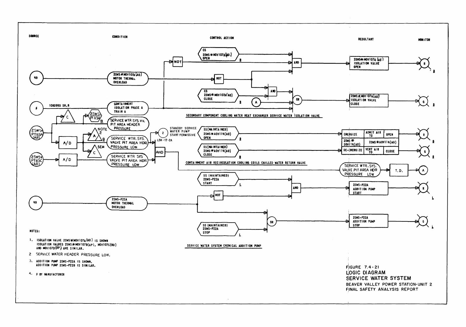
SOUICE
A/D
A/D
NOTES:
COlD IT I Oil
2SWS;II MOY I 07A MOTOR THERMlL OVERLOAD
CDNTl I liME liT ISOUTIOII PHASE A TRAIN A
SERVICE WTR SYS. VV. PIT AREA HEADER
PRESSURE
SERVICE WTR, SYS. VALVE PtT AREA HDR. .PRESSURE LOW
2SWS-P22A MOTOR THERMAL OVERLOAD
I, ISOUTIOII VALVE 2SWS*MDY107A.{AO) IS SHOWII ISOLATION VALVES 2SWS~MOYI07B(API, MOY107C(BO) AND MDY1070{BP) ARE SIMILAR.
2 SERVICE WATER HEADER PRESSURE LOW.
3, ADDITION PUMP 2SWS-P22A IS SHOWN, ADDITION PUMP 2SWS-P22B IS SIMILAR.
4. II BY MAIIUFACTURER
COIITROL ACT I 011
cs 2SWS*MOVI07A~) OPEN
cs 2SWS* MDV 1 D7A( AD) CLOSE
I
RESULT AliT
2SWS*MOV 1 074 (Ao· ) ISOLATIOtl VlLV£ OPE II
2SWS'*.MOY 107A AO )----------t:M ISOUTI 011 VALU
CLOSE
SECOIIDARY COMPONENT COOLING WATER HEAT EXCHANGER SERVICE WATER lSOLATION VALVE
STANDBY SERVICE WATER PUMP START PERMISSIVE
SS(MAINTAINED) 2SWS *lOY IIII(AO) OPEN
ADMIT AIR OPEN TO LSK-17-2A l
2SWS *AOYIIII(AO) SS(MAINUINED) 2SWS*AOYI III(AO} CLOSE '
I CONTAINMENT AIR RECIRCULATION COOLIN& COILS CHILLED WATER RETURN VALVE
CLOSE
SERVICE WTR.SY'S. L------;======~----------------------1 VALVE PIT AREA HDR
P ESSURE LOW T.D.
SS I NAINTAINEDI 2SWS-P22A START .!.
SS (NAINTAINEOI 2SWS-P22A STOP
SERVICE WATER SYSTEM CHEMICAL ADDITION PUMP
2SWS-P22A ADO IT I ON PUMP START
I 2SWS-P22A ADDITI 011 PUioiP STOP
~IGURE 7.4- 21 L;.OGIC DIAGRAM SERVICE WATER SYSTEM
MetiiTOit
BEAVER VALLEY POWER STATION-UNIT 2 F,INAL SAFETY ANALYSIS REPORT
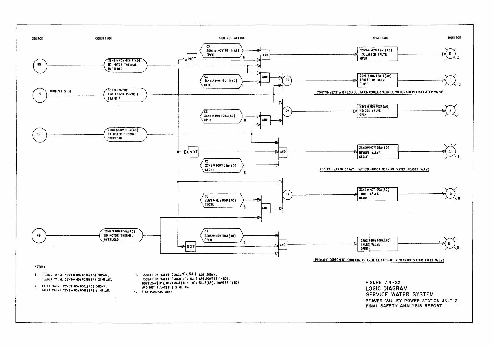
SOURCE
I 08099 3 SH. 8
NOTES:
CONDITION
2SWS"*;NOY 153-1 AO NO l«lTOR THERMAL OVERLOAD
CONTA IIINENT I SOLATION PHASE 8 TRAIN A
SWS"*-NDY 103A(AO) NO MOTOR THERMAL OYER LOAD
2SWS *MDVI 06A (AO) NO MOTOR THERMAL OVERLOAD
CONTROL ACTION
cs 2SWSl.<-MOYI53-1 (AD) OPEN
cs 2SWS,i; NOV 153-I(AO) CLOSE
cs 2SWS-* NOV I 03A (AD) OPEN
cs 2SWS~~OV103A{APl CLOSE
cs 2SWS *NOV I 06A (AD) CLOSE
cs 2SWS* MDV 1 06A (AD) OPEN
1. HEADER VALVE 2SWS* MDV 1 03A(AO) SHOWN, HEADER VALVE 2SWS* N!lV 1 038( BP) S IHI LAR.
3, ISOLATION VALVE 2SWS*MDV.!__53-I (AD) SHOWN,
2. INLET V.U VE 2SWSJiiHo!OVl 06A( AO) SHOWN, INLET VALVE 2SWS*MOV106B(BP) SIMILAR.
ISOLATION VALVE 2SWS* MDV I 53-21 AP) ,MOV152-J ( 80), MOY152-2{BP)3 MOV15~-1 (AO), MOVI5~-2(AP), MOV155-l(BO} AND NOV 155-2(BP) SIMILAR.
q, ' BY MANUFACTURER
RESULTANT
2SWU NOV153-l {AD) I SOLATION VALVE OPEN
2SWSfNOVI53-I (AO) 1--------------t3ill I SOLAri ON VALVE
CLOSE
CONTAINMENT AIR RECIRCULATION COOLER SERVICE WATER SUPPLY ISOLATOII Vf>J...VE
2SWS"*J.MOV 103A (AD) )--------------~ HEADE~ VALVE
OPEM
2SWS*iMOV1 03A(AO) 1-------------.e! HEADER VALVE
CLOSE
RECIRCULATION SPRAY HEAT EX£HANGER SERVICE WATER HEADER VALVE
2SWS ;(MDV I 06A (AD ) 1-------------~ INLET VALVE
CLOSE
2SWS *NOV 1 06A {AD) INLET; VALVE OPEN I
PRIMARY COMPONENT COOLING WATER HEAT EXCHANGER SERVICE WATER INLET VALVE
FIGURE 7.4-22 LOGIC DIAGRAM SERVICE WATER SYSTEM
MONITOR
B~AVER VALLEY POWER STATION-UNIT 2 FINAL SAFETY ANALYSIS REPORT
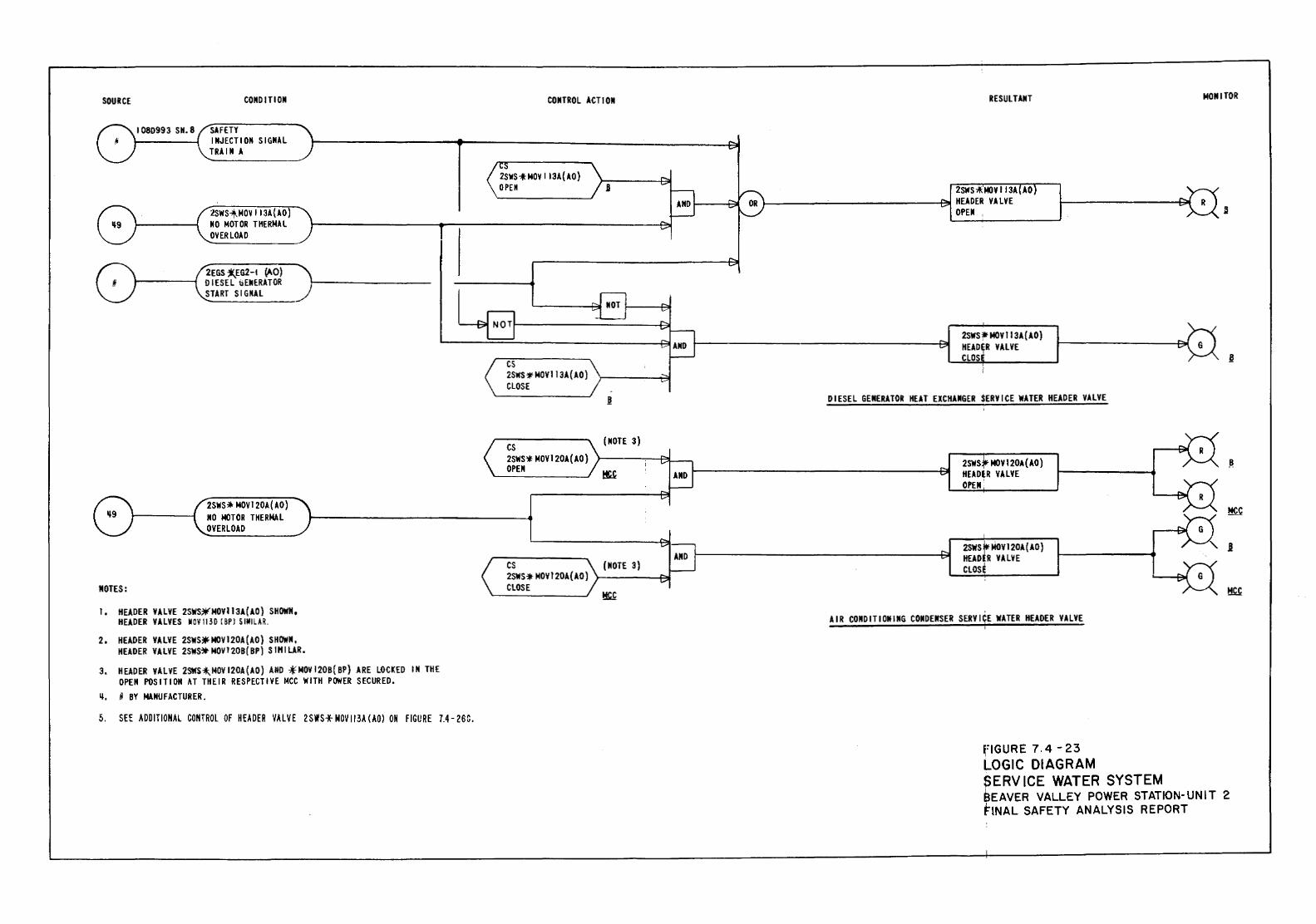
SOURCE
NOTES:
COND IliON
I 08D993 SH. 8 SAFETY IIIJECTI 011 S I GilA L TRAIII A
:.!SWSof_MOV 113A{AO) NO MOTOR THERMAL OVERLOAD
2EGS*.EG2-t (AO) DIESEL bENERATOR START SIGNAL
2SWS:* MOVI20A(AO) 110 MOTOR THERMAL OVERLOAD
!, HEADER VALVE 2SWS~MOVII3A(AO) SHOWN, HEADER VALVES MOV 1130 ( BPl S !MILAR.
2. HEADER VALVE 2SWS* MDV 120A (AD) SHOWN, HEADER VA LYE 2SWS~ NOV I 208 f BP J S 1 H ILAR.
3. HEADER VALVE 2SWS*.MDY 120A (AO) AND *NOV 1208( BP) ARE LOCKED I II THE OPEN POSITION AT THEIR RESPECTIVE MCC WITH POWER SECURED.
~. D BY MANUFACTURER.
5. SEE ADDITIONAL CONTROL OF HEADER ~AL~E 2 SWS* MOV 113A (AO) ON FIGURE 7.4- 26G.
CONTROL ACTI 011
2SWS-f NOV 113A(AO) OPEN
cs 2SWS1!' NOVI13A(AO) CLOSE
cs 2SWS* MOVI20A(AO) OPEN
(NOTE 3)
CS {NOTE 3) 2SWS* MOVI20A{AO) r------~ CLOSE
RESULTANT
2SWS~MOVII3A AO ~-----'---------811 HEADER VA LYE
OPEN
MONITOR
~ 2SWSj*MOVI13A{AO) ~ t-------------------P!JI HEAD~R VALVE t--------- G
~C~L~OS~--------~ §
DIESEL GENERATOR HEAT EXCHANGER SERVICE WATER HEADER VALVE
2SWS MOV120A{AO) HUDtR VALVE OPEN.
2SWS ~ MoV 120A (AD) HEADtR VALVE CLOS~
AIR CONDITIONING CONDENSER SERVICE WATER HEADER VALVE
~;IGURE 7.4-23 LOGIC DIAGRAM SERVICE WATER SYSTEM BEAVER VALLEY POWER STATION-UNIT 2 ~INAL SAFETY ANALYSIS REPORT
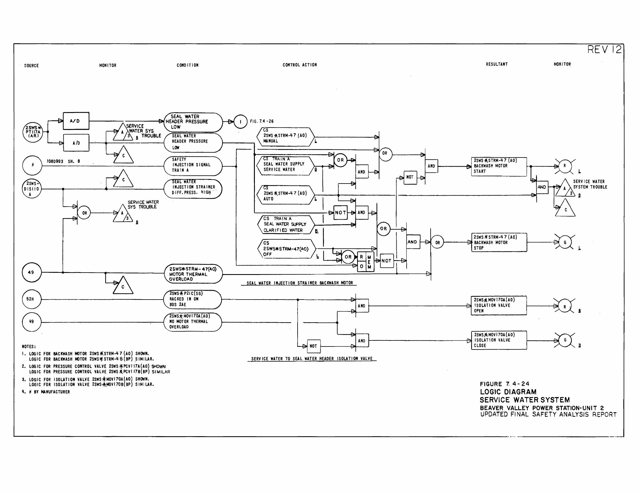
SOURCE MONITOR COMO IT I ON
A/0 SEAL WATER 1-----------...f:!W HEADER PRESSURE
A /o
1080993 SH. 8
SERVICE .----J::w A WATER SYS
B TROUBLE
SERVICE WATER SYS TROUBLE
LOW SEAL WATER HEADER PRESSURE LOW
SAFETY INJECTION SIGNAL TRAIN A
E W INJECT I ON STRAINER DIFF.PRESS. ltiGI} ..
2SWS*STR~- 47(AO) MOTOR THERMAL OVERLOAD
2SWS*P21C SG} RACKED IN ON BUS 2AE
· 2SWS;t MOV 170A (AO 1----------------~ ....... .,....._...,{ NO MOTOR THERMAL
OVERLOAD
NOTES: I. LOGIC FOR BACKWASH MOTOR 2SWS*.STRM-Ii7(AO) SHOWN.
LOGIC FOR BACKWASH MOTOR 2SWS*STRM-Ii8(BP) _SIMILAR. 2. LOGIC FOR PRESSURE CONTROL VALVE 2SWSfPCVI17A(AO) SHOWN
LOGIC FOR PRESSURE CONTROL VALVE 2SWS ;t,PCVII7B(BP) SIMILAR
3. LOGIC FOR ISOLATION VALVE 2SWS.fMOVI70A(AO) SHOWN. LOGIC FOR ISOLATION VALVE 2SWS~MOVI70B(BP) SIMILAR.
li. N BY MANUFACTURER
FIG. 7.4 ·26
cs
CONTROL ACT I ON
2SWS *-STRM-~ 7 (AO) MANUAL
AIN A SEAL WATER SUPPLY SERVICE WATER
s 2SWS *.STRM-~ 7 (AO) AUTO L
CS TRAIN A SEAL WATER SUPPLY CLARIFIED WATER
cs 2SWS*STRM-47(AO) OFF
NOT
SEAL WATER INJECTION STRAINER BACKWASH MOTOR
NOT
RESULTANT
2SWS *.STRM-~ 7 AO AND ~----t:ll)l BACKWASH MOTOR
START
2SWS *STRM-Ii 7 (AO) 1----~ BACKWASH MOTOR
STOP
2SWS*. MOV 170A ( AO) AND 1-----------------J:~ ISOLATION VALVE
OPEN
2SWS.*MOV 170A (AO) AND 1--------------~~ ISOLATION VALVf
MOtiiTOR
REVI2
.L
SERVICE WATER SYSTEM TROUBLE
3 .a
.L
I
NOT 1------94--..J CLOSE D
SERVICE WATER TO SEAL WATER HEADER ISOLATION VALVE
FIGURE 7. 4- 24 LOGIC DIAGRAM SERVICE WATER SYSTEM BEAVER VALLEY POWER STATION-UNIT 2 UPDATED Fl NAL SAFETY ANALYSIS REPORT
....._---------------------------------------------------------------------··-·-·--·------------
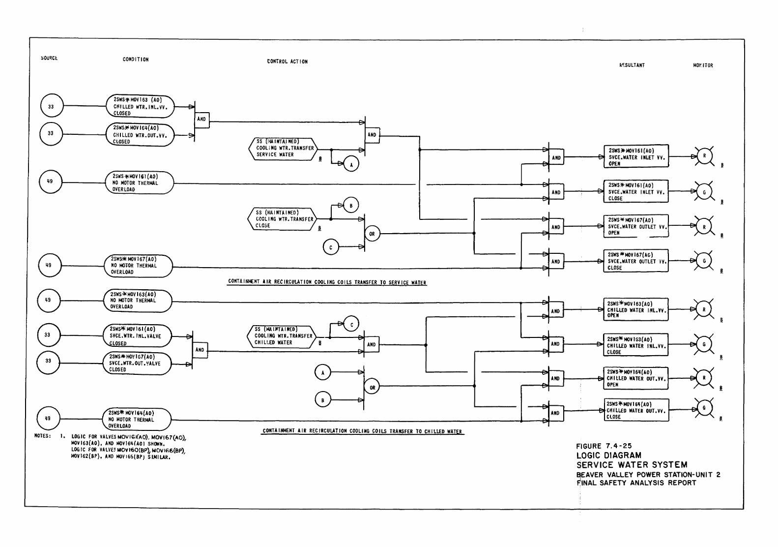
:,:ou~ct. CONDITION
2SWS'* MDV 163 ( AO) CHILLED WTR.INL,VV, CLOSED
2SWS:* MOV 16~(AO) Ctll LLED WTR. OUT. V V. CLOSED
2SWS *loiOV 16 I (AO) NO MOTOR THERMAL OVERLOAD
2SWS* MDV 167 ( AO) NO MOTOR THERMAL OVERLOAD
2SWS~MOV 163(AO) NO MOTOR THERMAL OVER LOAD
2SWS* MDV 161 {AD) SVCE.WTR. IHL.YALYE
LOS ED
2SWS*HOVIG7(AO) SYCE.WTR.OUT.~ALYE CLOSED
2SWS* MDV 16~ ( AO) NO MOTOR THERMAL OVERLOAD
NOTES: I. LOGIC FOR VALVES hiOV I GI(AO), MOV\67(AO), MOVI63{AO), AND MOVI6~(A01 SHOWN. LOG I C FOR VA LVH MOY 160(BP1 NOV 166(8P), MDVI62{BP), AND MOV165{8P) SIMILAR.
CONTROL ACT I ON
SS (MAINTAINED) CCGLI NG IIITR. TRANSFER }---6-----4==!11 CLOSE
CONTAINMENT AIR RECIRCULATION COOLING COILS TRANSFER TO SERVICE WATER
CONTAINMENT AIR RECIRCULATION COOLING COILS TRANSFER TO CHILLED WATER
kC.:SULTANT MO~ IT OR
2SWS.*MOYI61 {AO) 1----~ SVCE,WATER INLET YY • .,_--f::.t
OPEN
2SWS*MDV 161 {AO) 1------~~ SYCE.WATER lttLET VV. 1---......,illl
CLOSE
2SWS* MDV 167( AO) 1--------l:::;.t SYCE.WATER OUTLET VY.~-~
OPEN
2SWS •MDV 167(AG) ,__----t=-t SVCE.WATER OUTLET ·1v. ~--8(
CLOSE
FIGURE 7.4-25 LOGIC DIAGRAM SERVICE WATER SYSTEM B;EAVER VALLEY POWER STATION-UNIT 2 FINAL SAFETY ANALYSIS REPORT
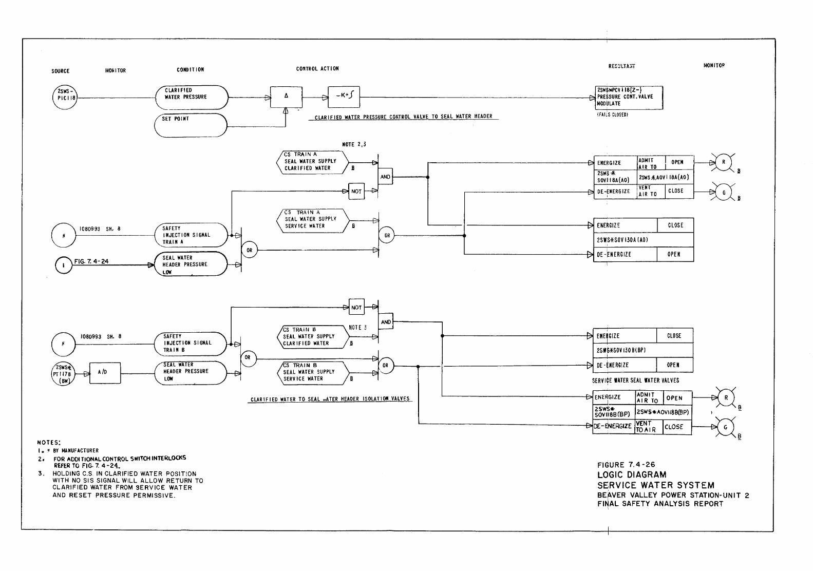
SOURCE rtOiiiTOR
I 080993 SH. 8
FIG. 7. 4-24
1080993 SH. 8
A /D
NOTES: I.~ BY ~NUFACTURER
CONDITION
CLARI FlED WATER PRESSURE
SET POINT
SAFETY INJECTION SIGNAL TRAIN A
SEAL WATER HEAD Ell PRESSURE LOW
SAFETY INJECTION SIGNAL TRAIN B
SEAL WATER HEADER PRESSURE LOW
2• FOR ADDITIONAL CONTROL SWITCH INTERLOCKS REFER TO FIG· 7. 4-24.
3. HOLDING C.S. IN CLARIFIED WATER POSITION WITH NO SIS SIGNAL WILL ALLOW RETURN TO CLARIFIED WATER FROM SERVICE WATER AND RESET PRESSURE PERMISSIVE.
COli Til OL ACTION
-K+f
RES:JLTAiiT
2SW$~V IIB(Z-) t---------------------------j:::>j PRESSURE CONT. VALVE
MODULATE
C LAR I F I ED WATER PR ESSU R£ COtiTR Ol VALVE TO SEAl WATER HEADER (fAILS CLOSED)
CS TRAIN A SEAl WATER SUPPLY CLAR I FlED WATER
CS TRAIN A SEAl WATER SUPPLY SERVICE WATER
CS TRAit~ B SEAl WATER SUPPLY CLARIFIED WATER
NOTE 2,3
fl
..-------------------P!I ENERGIZE ADMIT OPEN AIR TO
~z=s~ws~~=--~~~_J __ _, SOV II SA (AO) 2SWH.AOV I ISA (AD)
.---------------P>!! DE-ENERGIZE '
VENT AIR TO
2SW:S*SOV 130A ( AO l
e----------------~ EKE~SilE
CLOSE
CLOSE
OPEK
CLOSE ~~·--------~L-----~
2SW&fSOV 130 B ( BP l '
CS TRAIN B ,___...,.. __ ----------------91 OE-[NERGIZE OPEN SEAl WATER SUPPLY SERVICE WATER
CLARIFIED WATER TO SEAL nATER HEADER ISOLAT 1 ON VALVES
L-------------L-----~
SERVI~E WATER SEAL lATER VALVES
'-----------------~ENERGIZE ADMIT OPEN • AIR TO
zsws• SOVIISB(BP) 2SWS*AOVII8B(BP)
.__ ________________ ~DE-ENERGIZE ¥6~TR CLOSE
FIGURE 7. 4-26 LOGIC DIAGRAM
MONITO~
SERVICE WATER SYSTEM
B
8
BEAVER VALLEY POWER STATION-UNIT 2 FI~AL SAFETY ANALYSIS REPORT
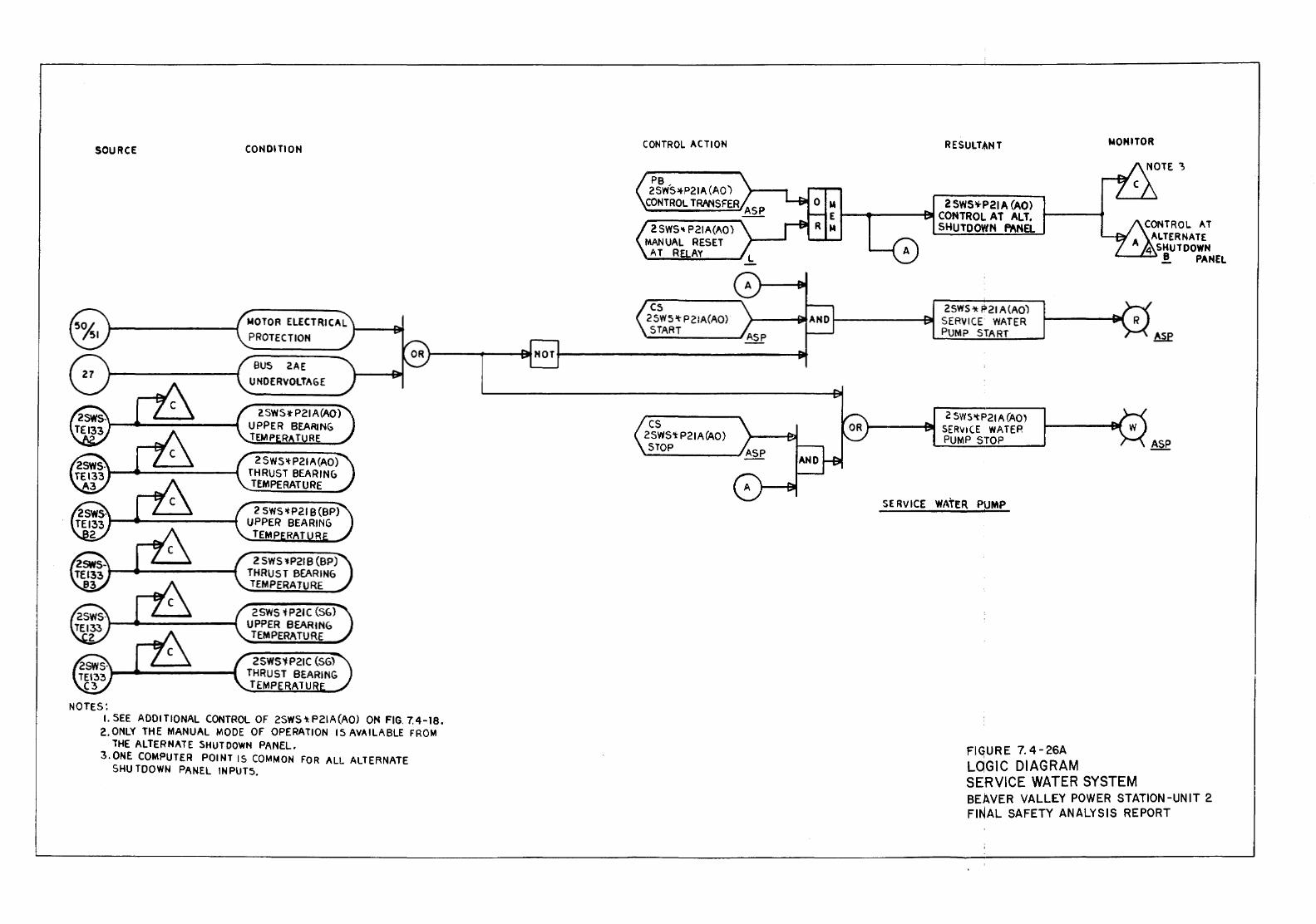
SOURCE
NOTES:
CONDITION
PROTECTION
BUS 2AE UNDERVOLTAGE
2SWS~t-P21A(AO) THRUST BEARIN() TEMPERATURE
2 SWS ~P21B (BP) THRUST BEARING TEMPERATURE
25WS 'tP21C (S{,) UPPER BEARING TEMPERATURE
2SWS'f:P21C (SG) THRUST BEARING TEMPERATU
I. SEE ADO I TIONAL CONTROL OF 2SWS "1: P 21 A (AO) ON FIG. 7. 4-18. 2.0NLY THE MANUAL MODE OF OPERATION 15 AVAILABLE FROM
THE ALTERNATE SHUTDOWN PANEL. 3.0NE COMPUTER POINT IS COMMON FOR ALL ALTERNATE
SHU TOOWN PANEL INPUTS,
CONTROL ACTION
2 SWS" P21A(AO) MANUAL RESET
AT RaAY
C5 25W5't P2!A(AO) START
cs 2SWS'tP21A(AO) STOP
RESULTANT NOHITOR
M 2 SWSll-P21 A (AO) E t---1---""1'1 CONTROL AT ALT.
CONTROL. AT
SERVICE
SHUTDOWN PANEL
2SWS"'k P21 A(AO) SERVICE WATER PUMP START
2 5WS'tP21 A (AO) SER\11 CE WATER PUMP STOP
WATER PUMP
FIG;UR E 7. 4- 26A
ALTERNATE 4 SHUTDOWN
....._........._~ .! PANEL
Asp
ASP
LOGIC DIAGRAM SERVICE WATER SYSTEM BEAVER VALLEY POWER STATION-UNIT 2 FINAL SAFETY ANALYSIS REPORT
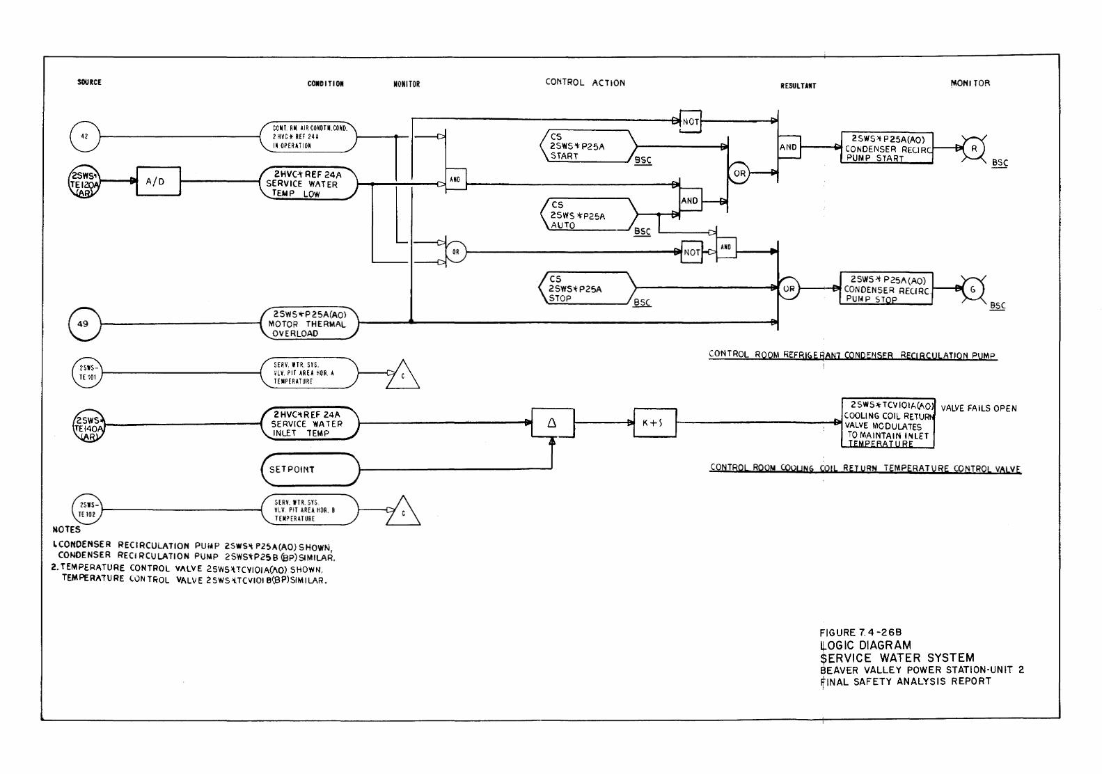
SOURCE
A/D
NOTES
COMOITIOII
CONT. RM A I R CO NOT N. COND. 2 HVC * REF 24A IN OPE RAT ION
2HVC-tREF 24A 1-------f SERVICE WATER
TEMP LOW
2 SWS >rP 25A(A0) MOTOR THERMAL OVERLOAD
S fRY. W T R. S YS. '/LV. PIT AREA HOR. A TEMPERATURE
2HVC>tREF 24A SERVICE WATER INLET TEMP
SETPOII'iT
SERV. ITR. SYS. VLV. PIT AREA HDR. 8 TEMP ERHURE
LCONOENSER RECIRCULATION PUhiP 2SWS-'t PZ5A(AO) SHOWN, CONDENSER RECIRCULATION PUMP 25WS'tP2~B (SP)SIMILAR.
2. TEMPERATURE CONTROL VALVE 2SWS.\I.TC\IIO!A(AO) SHOWN, TEMPERATURE CON TF;-QL VALVE 2SWS.!J.TCVIOI B(BP)SIMILAR.
MONITOR CONTROL ACTION
cs 2SWS>t- P25A START
cs 2SWS >I:'P25A AUTO
cs 25WS>I-P25A STOP
K+S
RESULTANT MONITOR
2SWS:>t P25A(AO) l------4iit C 0 N DENSER RECI R 1----1~
PUMP START
ZSWS.>t P25A(AO) ,____.._....;,.CONDENSER REURCI----1~
PU!llP ST
CONTROL ROOM REFRIGE FfANJ CONDENSER RE(! RCULATION PUMP
ZSWS·HCVIOI,'..(/\0 VALVE FAILS OPEN COOLING COIL RE'TU
..__-----------~ VALVE MCDULA'TES TO MAINTAIN INLET
CON'TROL RQOM COOUNG COIL RET URN TEMPERATURE CONTROL VALVE
FIGURE 7. 4-268 ~OGIC DIAGRAM $ERVICE WATER SYSTEM BEAVER VALLEY POWER STATION-UNIT 2 ~INAL SAFETY ANALYSIS REPORT
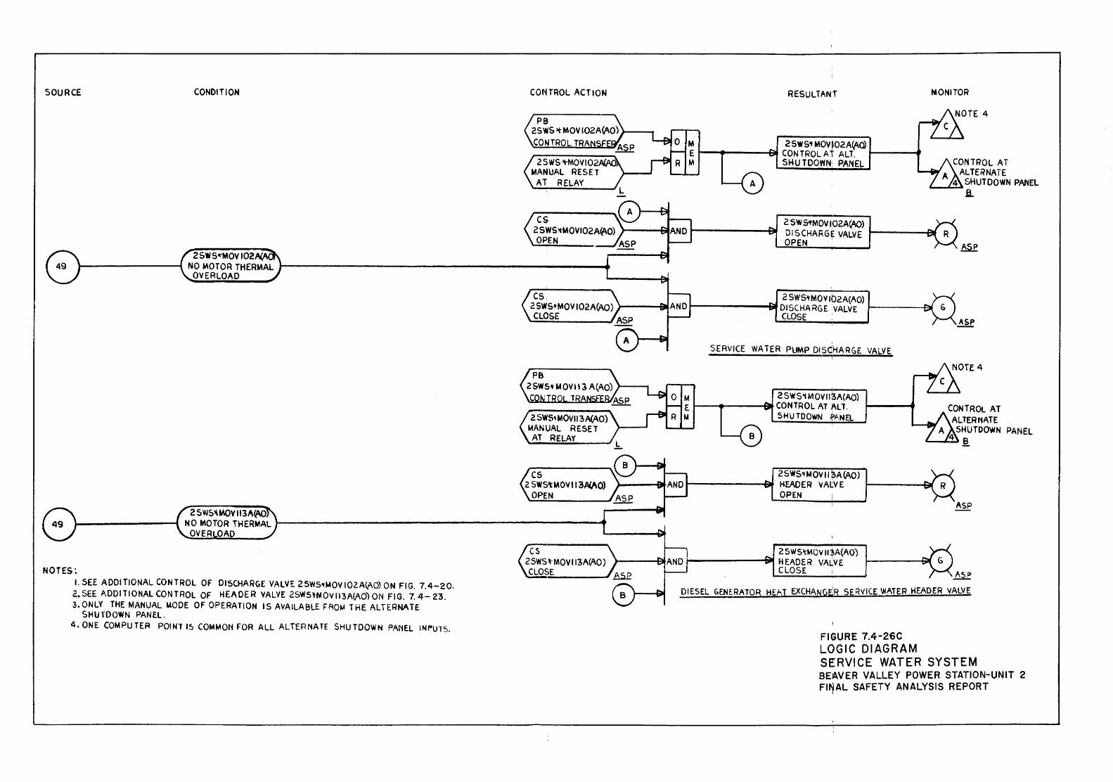
SOURCE CONDITION
NOTES: 1. SEE ADDITIONAL CONTROL OF DISCHARGE VALVE 25WS>tMOV 102A(AO) ON FIG. 7.4-20. 2. SEE ADO IT I ONAL CONTROL OF HEADER VALVE 2SWS'tM OV 113A(AO) ON FIG. 7. 4- 23. 3.0NLY THE MANUAL UODE OF OPERATION IS AVAILABLE FRO~ THE ALTERNATE
SHU fDOWN PANEL. 4. ONE COMPU TEA POINT 15 COMMON FOR All ALTERNATE SHU TOOWN PANEL INF'UT5.
CONTROL ACTION
PB 2SWS >t MOVI02A~O) l---. CONTROL TRA
2 SWS >t-MOVIO MANUAL RESET
AT RELA'<
cs. 2 SWS~MOV 102ACAO) )-----BI CLOSE
2 SWS~ MOVI13 Af..AO) MANUAL RESET
AT RELAY ~~~~--~~
cs 2 SWS\ MOY 113/!JI/\0)
OPEN
cs 2SWS:tMOVI13A(AO) CLOSE
RESULTANT MONITOR
M 25WS'tMOV~02A{AO) E 1---.----Bt CONTROL AT ALT. f----4 M SHU TOOWN: PANEL
2 SW S'tMOV 102AV\C) DISCHARGE VALVE 1------af OPEN .
2 SW5'1M0VIb2A(AO) 1-------lif DISCHARGE ·vALVE 1------et
ClOSE .
SERVICE WATER PUMP DISdHARGE VALVE
2 S W S>t M OV lli3A(AO) 1---e-----at CONTROL AT ALT.
SHU TO OWN ~f',NEL
2SW5'1'MQVII ~A CAO) 1---------t:W HEADER VAtVE 1------et
OPEN
2 SWS'tMOV II!A(AO) 1-------t:i)l HEADER VALVE
CLOSE
DIESEL GENERATOR HEAT EXCHANGE:R SERVICE WATER HEADER VALVE
FIGURE 7.4-26C LOGIC DIAGRAM SERVICE WATER SYSTEM BEAVER VALLEY POWER STATION-UNIT 2 FI~AL SAFETY ANALYSIS REPORT
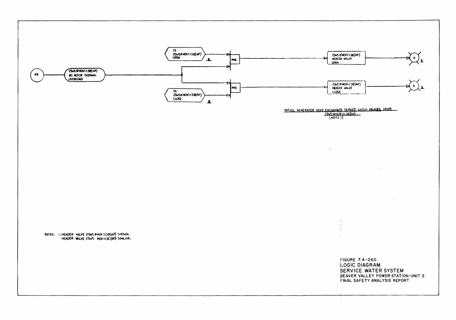
29.f'SfNOr'1131(4P) 10 f()TOI TH(RMI.l OYERl.OW
MOTES: 1 o HEADER VALVE 2SWS t...,., 1138{AP) SI-0\./N o
HOOER 'tkLVE 2SWS HOI113C (BO) SIMILAR •
ts ZSWS*IOII138(AP) CI'£H
cs
.JL
zsws.: ~113 ~""') }-----i:.,t CLOSE
~------------- ~ t€1-tf.~ 't,.LVf 1-· --------t- n ~ 25W~:«<~IIl8(AJ<) ·1 ~., " ~~0"-'ft.:..:.h""\",:-----...J
_OifSEL "t:HEBAIOB HEAT fta':Js!\cfelti f!A!tH HEA'*b VALVE
~NOTE 1)
I;IGURE 7.4-260 LOGIC DIAGRAM ,SERVICE WATER SYSTEM f3EAVER VALLEY POWER STATION-UNIT 2 fiNAL SAFETY ANALYSIS REPORT
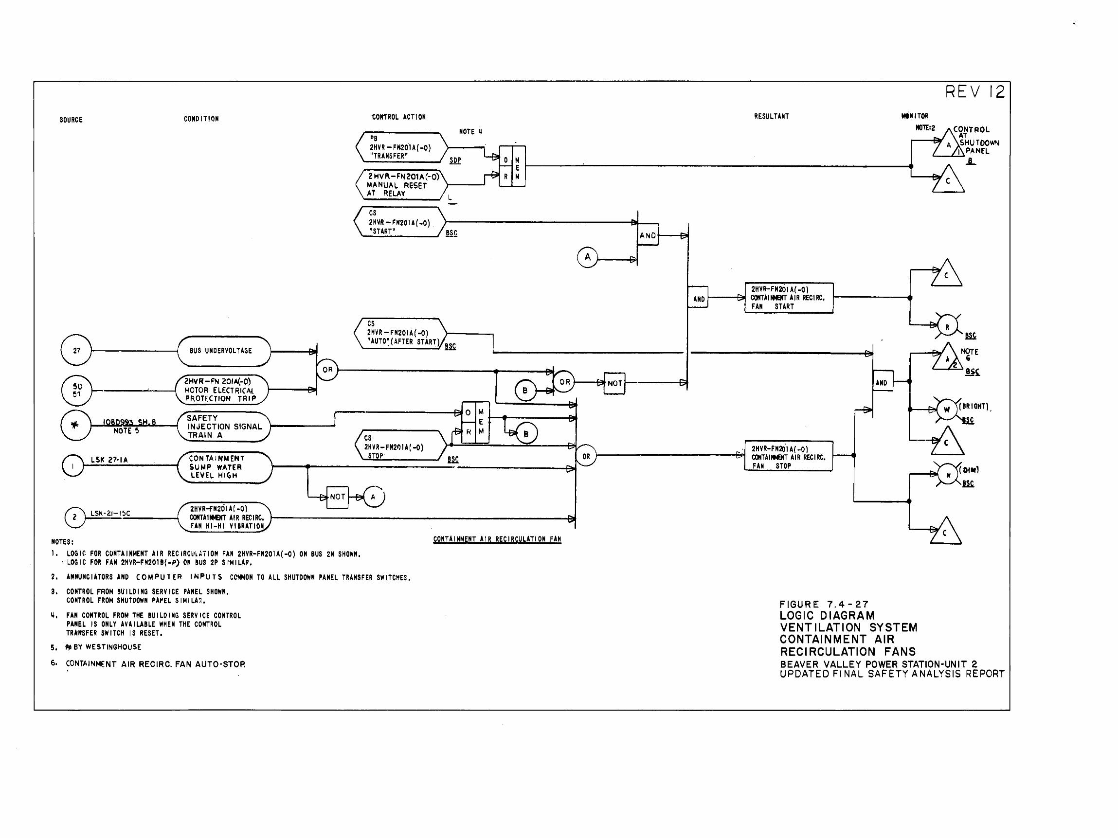
BUS UNDERVOLTAGE
®- 2HVR -FN 201A{-0) 1 ------------~--~ """~-0-TO-R--EL_E_cr_R_IC-A-l.~ ~----~~ PROTECTION TRIP
LSI< 27·1A
~5~C--------~
NOTES:
SAFETY INJECTION SIGNAL TRAlN A
CONTAINWENT SUMFI WATER LEVEL HIGH
2HVR-FN201A(-O) COMTAIMMT AIR RECIRC, FAN HI-HI VIBRATION
""--'"' N 0 T
1. LOGIC: FOR CONTAINMENT AIR RECIRCliLA'iiON FAN 2HVR-FN201A(-O} ON BUS 2N SHOWN, ·LOGIC FOR FAN 2HVR-FN2018(-P) ON BUS 2P SI'MILAP.
cs 2HVR- FN20IA( -0) "AUTO~(AFTER START)
cs 2HVR-FN2t>1A( -0}
STOP
CONTAINMENT AIR RECIRCULATION FAN
2. ANNUNCIATORS AND COMPUl ER INPUTS CCMMON TO ALL SHUTDOWN PANEL TRANSFER SWITCHES. 3, CONTROL FROM BUILDING SERVICE PANEL SHOWN.
CONTROL FROM SHUTDOWN PA~EL SIMILA~. ~. FAN CONTROL FROM THE BUILDING SERVICE CONTROL
PANEL IS ONLY AVAILABLE WHEN THE CONTROL TRA'JrtSFER SWITCH IS RESET.
5. ~BY WESTINGHOUSE
6. CONTAINMENT AIR RECIRC. FAN AUTO-STOP. '
REV 12 RESULTANT ~NITOR
MO'TE:2 CONTROL AT
2HVR-FN201A( -0) AND t---~ COMTAIItBT AIR RECIRC.
FAN START
2HVR-FN2)1 A( -0) COO'AINMBIT AIR RECIRC, FAN STOP
FIGURE 7.4-27
AND 1--4
LOGIC DIAGRAM VENTILATION SYSTEM CONTAINMENT AIR RECIRCULATION FANS
A SHUTOOW"-4 1 PANEL
'----"'-~..L
[ Dlflll,
ill.
BEAVER VALLEY POWER STATION-UNIT 2 UPDATED Fl NAL SAFETY ANALYSIS REPO~T
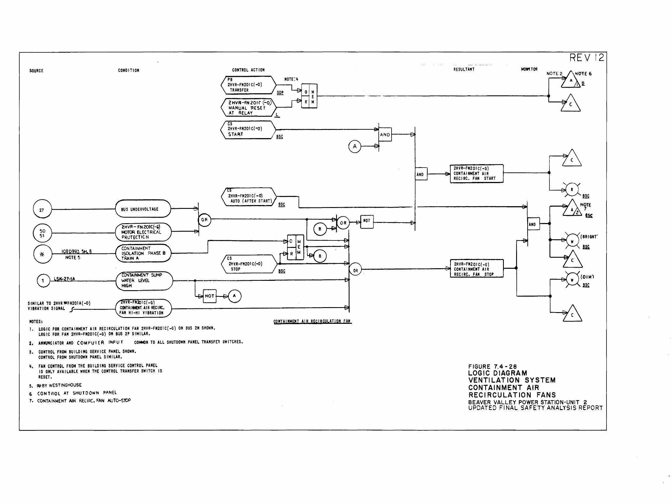
SOURCE
108099., NOTE~
8 LS.K-27-lA
SIMILAR TO 2HVR *FN201A( -0)
COMO I Tl ON
BUS UNDERVOLTAGE
2HVR- FN201C(-') MOTOR ELECTRICAL PROTECT IC N
CONTAIN~~ENT ISOLATION PHASf. B
.TRAIN A
c:ONTAINMENT SUMP )
HIGH . WATER LEVEL 1-----~~~-
VIBRATION SIGNAL .f-------1
NOTES: 1. LOGIC FOR CONTAINMENT AIR RECIRCULATION FAN 2HVR-FN201C(-G) ON BUS 2N SHOWN,
LOGIC FOR FAN 2HVR-FN201C(-G) ON BUS 2P SIMILAR.
CONTROL ACTION
PB 2HVR-FN201C(·O)
TRANSFER
2 HVA-FN 201 r (-0) MANUAL 'RESET \------' AT RELAY
cs 2HVR-FN201C(·O) STAAT
2HVR-FN201 C( -0) AUTO {AFTER START)
cs 2HVR-FN201C(·O)
STOP
BSC
CONTAINMENT AIR RECIRCULATION FAN
2. ANNUNCIATOR AND CONPUlER INF-1.1 r CO~ON TO ALL SHUTDOWN PANEL TRANSFE~ SWITCHES.
S. CONTROL FROM BUILDING SERVICE PANEL SHOWN. CONTROL FROM SHUTDOWN PANEL SIMILAR.
~. FAN CONTROL FROM THE BUILDING SERVICE CONTROL PANEL IS ONLY AVAILABLE WHEN THE CONTROL TRANSFER SWITCH IS RESET,
5. ~BY WESTINGHOUSE
6 CONTP.OL AT SHUTDOWN P~NEL
7, CONTAINMENT AIH RECIRC. FAN AUTO-SlOP
AND"--~
RESULTANT
2HVR'-FN201 C( -G) CONTAINMENT AIR RECIRC. FAN START
MOW! TOR
AND
2HVR-FN20l C( -G) .._-----------t::iJt CONTAINMENT AIR RECIRC, FAN STOP
FIGURE 7.4-28 LOGIC DIAGRAM VENTILATION SYSTEM CONTAINMENT AIR REC I RCU LAT 10 N FANS
REV r2
(BRIGHT'
BEAVER VALLEY POWER STATION-UNIT 2 UPDATED FINAL SAFETY ANALYSIS REPORT
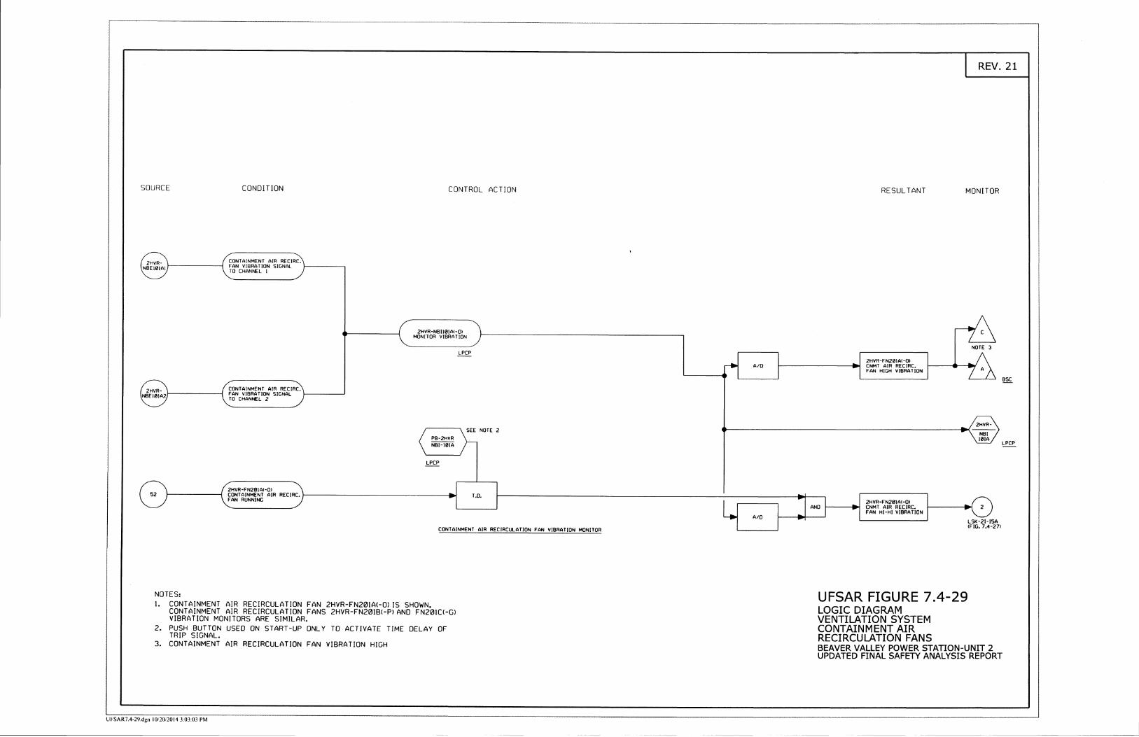
F rn s NJ
ts
a C)
C T c-)
m r-) c) z g 5 z cl C
f z n c) r D c-) 5 z fJ m a C -{ D z 3 O = cf D
IE
a) o z D 2 3 m z I ! D m r-) a, n c D { o z 'rl D z s @ T D 6 z 3 o = o 7t
35
PT
:! \l *F
(^)
N
:-Z
rr
o
cl -
{T
<r)
c)
mO
flC
=
OO
t0
z-a
Y
zz
'r
{ v
I *-
{-r
D,^
{D
DH
v,
l.i
l
z =
F
=z
z3
y.
Y3
3lr
l ii-
r -m
mz
Fo
-z
Z-r
l z
a
--D
c
=>
>i
H-;
;u
o
T:o
nm
v
rmm
! T
fJfJ
;!c)
a
mc-
)c-)
C
{ C
Ct-
D
(nr
r-
D
N =
DD
-{
{ -S
-1
-1H
,
l
HH
o
cr_
oo
z
Tz
zz
).)-t
'l
cJ'
rlr
D
Z
DD
zrz
z
=
{ N
-H
O
T
<{
<f]
a 3
T
+f-
t -l
.a
Z-
=
zN
15
NS
r39
;6
mP
rf
rO{
!- YF
a
3 s(
/)m
t3
ao
-:
Em
nO
r z
tq
N
z
o6
Tl?
g
gH F
Q<
tr C
EH
fl??E
T
dt A
tFo
;f i=
rs F
=f; =f
fidB
xl:
Az_
=tg
=xY
'a
+zz
'><
'i= T
=a
Fl;"
>*i
rn
},2F
' =
!rii 2>
N
Ja)
- \o
H=
r--l $ru
-{
z Hry 53
Dr
N
{ a
lno
Dc) zz
c")
I<D
9;,2
83fi
|--|
z-.
o-
,vZ
Dg
i9
a=
m r37 P
{ -n
C)
oD
oz
z(-
) -{
I<D
9A
Ze3
fir1
2 o-
-z> ai 6r
=m r!D c-
)
3 c)N
z- =s
oa
D2 sg @
(9 ilT 69
z
1111
ND
ZI
2-= -{
A)
Il Fi6 o
<r= EB
fD
:o Y
rr')
o z
E6
DE
1r1
ND
OI
zz
< {ft
PP
+-z
zz
i!rv
-mG
)
6=
' I
99
7t D m r) I, r)
zl!
ol@ ili Dll
,
TN
N>
zr
=1
;is
l*r
3 6Ei
DT
==
PC
] z
C -c U)
F { :5 I l.J \0 b- q9 l\) l.J E b UJ
(}J
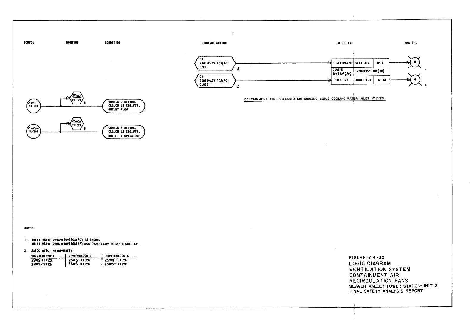
SOUtCE MONITOR
JIOTES:
1. IJILET Y.llYE 2SWS~.lOYIIO.l(AO) IS SHOWN.
COJIDITIOII
COifT.AIR RECIRC. CLG.COILS CLG.WTR. OUTLET FLOW
COJIT.AIR RECIRC. CLG.COILS CLG.WTR. OUTLET T-EMPERATURE
INLET Y.llYE 2SWS*AOYIIOB(BP) AND 2SWS•AOV110C\SOl SIMILAR.
2. ASSOCIATED INSTRUMEifTS: 2HYR* CLC201.l 2SWS-FTI32.l 2SWS-TEI32A
2HYR~CLC2018
2.SWS-FT 1328 2SWS-TEI328
2HVRilfCLC201 C 2SWS-FT132C zsws-TEI32C
COIITROL ACTION
cs 2SWS~AOVIIOA(AO} OPEN !
cs 2SWS~AOYIIOA(AO) CLOSE !
RESULTAMT MONITOR
VENT AIR OPEN
2SWS1-AOY I lOA ( AO)
ADMIT AIR CLOSE
CONTAINMENT AIR RECIRCULATION COOLING COILS COOLING WA'$R INLET VALVES
FIGURE 7.4-30 LQGIC DIAGRAM V~NTILATION SYSTEM CONTAINMENT AIR RECIRCULATION FANS
~
R
B~AVER VALLEY POWER STATION-UNIT 2 FINAL SAFETY ANALYSIS REPORT
!
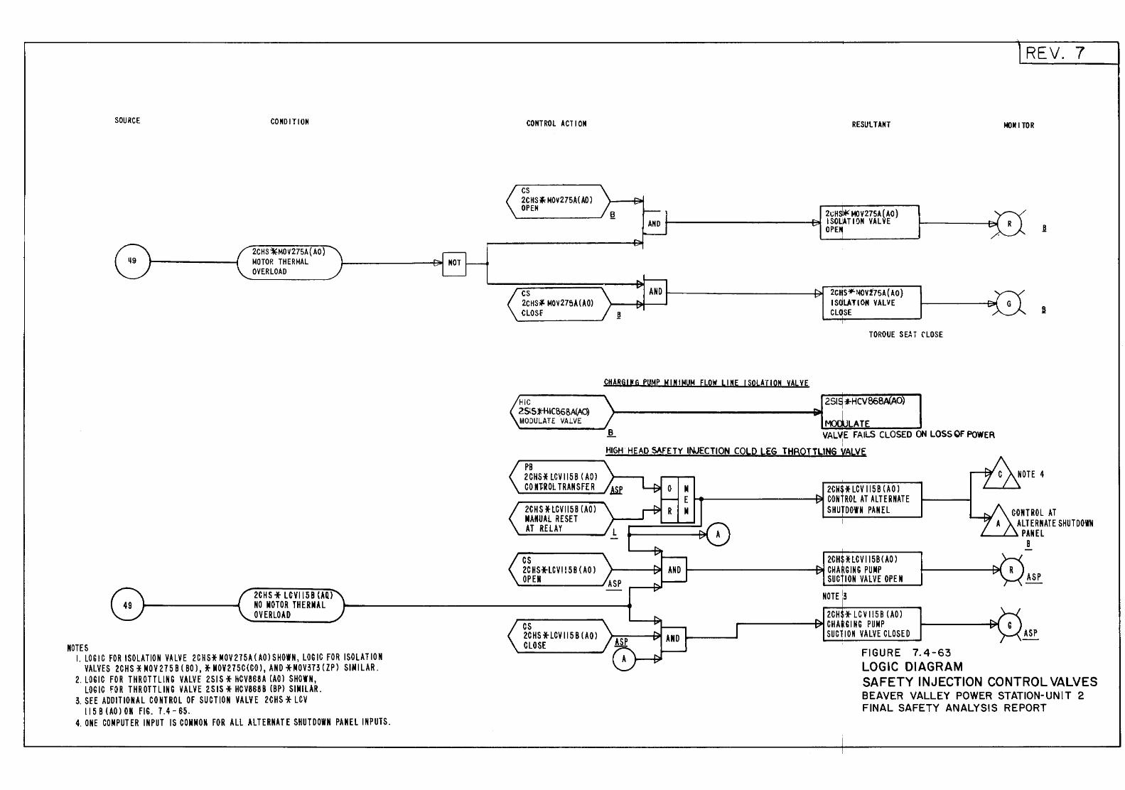
SOURCE
NOTES
CONDITION
2CHS~MOV275A{AO) MOTOR THERMAL OVERLOAD
2CHS * LCVIl58 (AQ) NO MOTOR THERMAL OVERLOAD
I. LOGIC FOR ISOLATION VALVE 2CHS* MOV 215A ( AO l SHOWN 1 LOGIC FOR ISOLAT 10 N VALVES 2CHS * MOV 215 B ( BO l 1 * MOV215C{CO 11 AND *MOV313 (ZPl SIMILAR.
2. LOGIC FOR T HROTTL IN G VALVE 2S IS* HCV868A (AO l SHOWN 1
LOG lC FOR T HR OTT LING VALVE 2 SIS* HC V868 B (BPl SIMILAR. 3. SEE ADDITIONAL CONTROL OF SU CTlO N VALVE 2CHS * LCV
ll5B{AOlOH FIG. 7.4-65. 4. ONE COMPUTER IN PUT l S COMMON FOR ALL ALTERNATE SHUT DOWN PANEl l NP UTS.
CONTROl ACTION
cs 2CHS* MOV275A(A0) OPEN
cs 2CHS~ MOV275A(A0) CLOSf
HIC 2S!St"HIC~68A(AO) MODULATE VALVE
RESULTANT
2~H MOV275A(AO) 1----------~ ISOliATIIJN VALVE
CHARG!!G PUMP MINIMUM FLOW LINE ISOLATION VALVE
OPE~
2CHS~~V175A{AO) I SOLATION VALVE CL~SE
TORQUE S~T rLOSE
LATE ~ 1/ALVE FAILS CLOSED ON LOSS OF POWER
I I
HIGH HEAD SAFETY INJECTION COLD LEG THROTTLING VALVE
REV. 7
NON I TOR
,.------...... P8 2CHS* LCVII58 ( AOl COn'ROL TRANSFER
2CH S * LCVII5 8 {AO l MANUAl RESET AT RElAY
cs 2CHS*LCV!! 58 ( AO l OPEN
cs 2CHS *LCV 115 B (AOl CLOSE
2CH$* LCV 1158 (AO l ...... --------91 CONtROl AT ALTERNATE
SHU DOWN PANEl
2CHf. HCV115B(AO l t-----------e~ CHA GJNG PUMP
SUC ION VAL V£ OPEN
2CH *LCVI!SB (AOl -------+~CHA,GING PUMP
SUCTION VALVE CLOSED
FIGURE 7.4-63 LOGIC DIAGRAM
CONTROL AT ALTERNATE SHUTDOWN
"----L..~ PAN El B
ASP
ASP
SAFETY INJECTION CONTROL VALVES BEAVER VALLEY POWER STATION-UNIT 2 FINAL SAFETY ANALYSIS REPORT
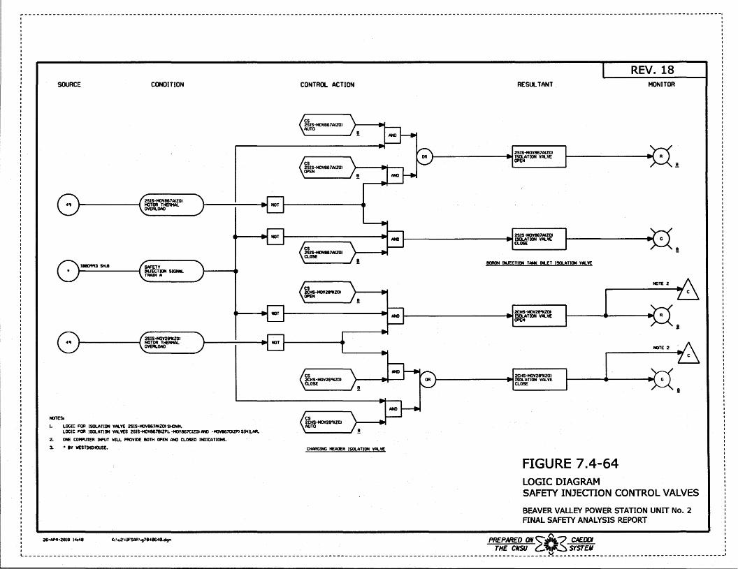
SOURCE CONDITION CONTROL ACTION
2SIS·MOV867AIZOI 4'1 MOTOR THERMAL NOT
OVERLOAD
11180'1'13 SH.II SAFE TV INJECTION SIGNM. TRAIN A
!
NOT
2SIS·MOV28'11Z0l 4'1 MOTOR THERMAL NOT
OVERLOAD
NOTES.
1. LOGIC FOR ISOLATION VALVE 2SIS·MOV867AIZOI SHOWN. LOGIC FOR ISOLATION VALVES 2SIS·MOVII678CZPI, -MOV867CCZOI ANO ·MOV86701ZPI SIMILAR.
2. ONE COMPUTER INPUT WILL PROVIOE BOTH OPEN ANO CLOSEO INDICATIONS. 3. • BY WESTINGHOUSE. CHARGING HEAOER ISOLATION VALVE
K1\u2\lFSAR\g78411648.dgn
RESULTANT
2SIS·MOV867AIZOI )---------.... ISOLATION VALVE
OPEN
2SIS-MOVII67AIZI» ISOLATION VAI.YE CLOSE
80RON INJECTION TANK INLET ISOLATION VAI.YE
2CHS·MOV2ti'IIZOI ISOLATION VAl. VE OPEN
2CHS·MOV28'11ZOI ISOLATION VALVE CLOSE
FIGURE 7.4-64 LOGIC DIAGRAM
REV. 18 MONITOR
.!.
!
NOTE 2
R
NOTE 2
!
SAFETY INJECfiON CONTROL VALVES
BEAVER VALLEY POWER STATION UNIT No. 2 FINAL SAFElY ANALYSIS REPORT
I I
PREPARED ONC::::J'"&? CAEDDI : THE CNSU ~-..---~ SYSTEM :
L---------------------------------------------------------------------------------------------------------------------------------~------------------------------------------1
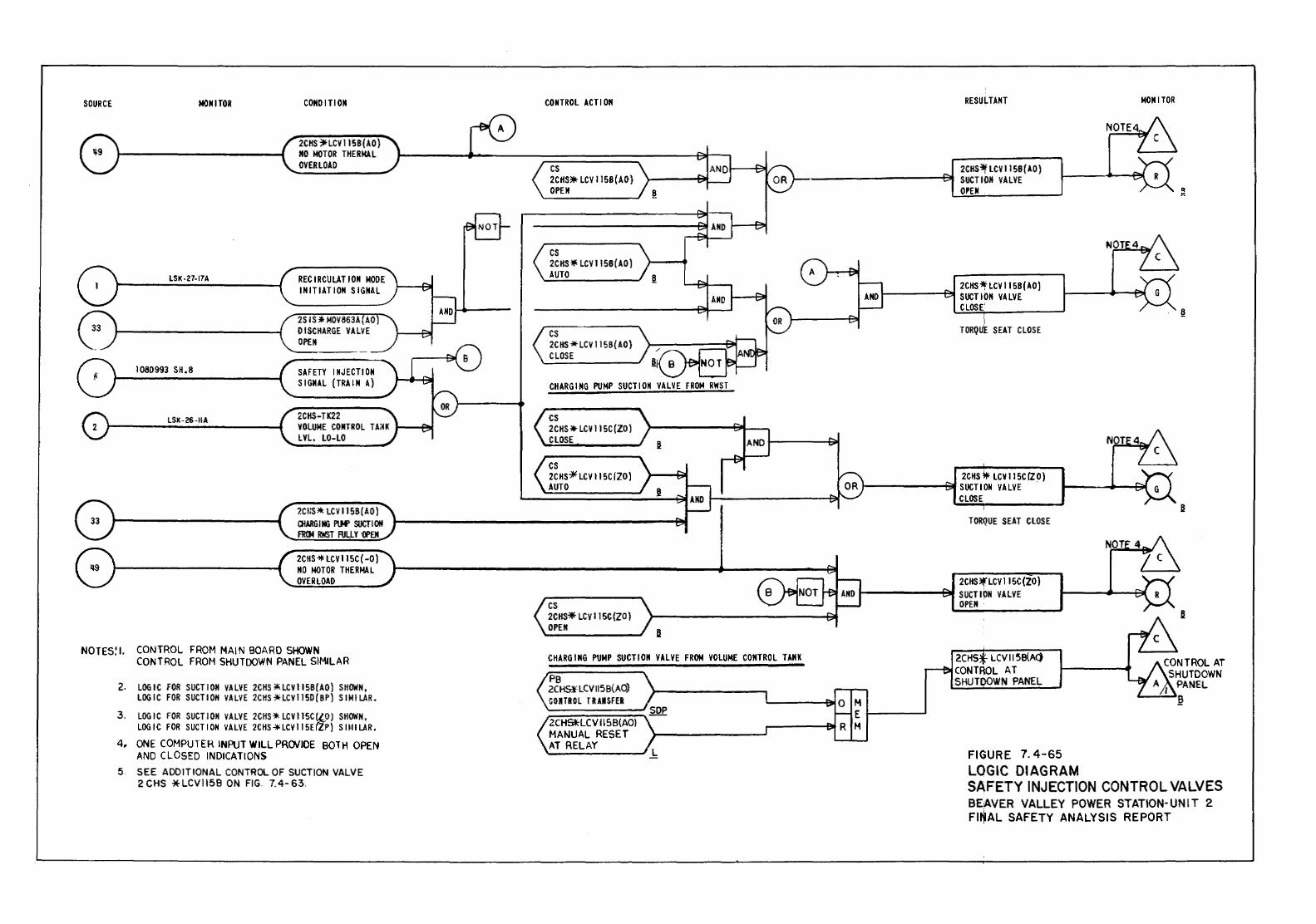
SOURCE MONITOR
LSK-27-17A
1080993 SH.8
LSK-26-IIA
CONDITION
2CHS ~LCV 115B(AO) NO MOTOR THERMAL OVERLOAD
RECIRCULATION MODE II+ITIATION SIGNAL
2S IS* MOV863A(AO} DISCHARGE VALVE OPEN
SAFETY I NJ ECTI ON SIGNAL (TRAIN A)
l:CHS-TK22 VOLUME CONTROL TA;~K 1----F~
LVL. LO-LO
7.CI1S* LCV 115S(AO) CHARGING PlM' SUCTION F1!()4 RWST RILLY ·OPEN
2CHS*LCV115C( -0) NO MOTOR THERMAL OVERLOAD
NOTES:L CONTROL FROM MAIN BOARD SHOWN CONTROL FROM SHUTDOWN PANEL SIMILAR
2. LOGIC FOR SUCTION VA LYE 2CHS * LCV 115B(AO) SHOWN, LOGIC FOR SUCTION VALVE 2CHS'*'LCV115D{BP) SIMILAR.
3. LOGIC FOR SUCTION VALVE 2CHS* LCV 115C (l_O) SHOWN, LOGIC FOR SUCTION VALVE 2CHS~LCV115E(ZP) SIMILAR.
4. ONE COMPUTER INPUT WILLPRCWIOE BOlH OPEN AND CLOSED INDICATIONS
5. SEE ADDITIONAL CONTROL OF SUCTION VALVE 2 CHS * LCV1158 ON FIG. 7.4- 63.
CONTROL ACTION
cs 2CHS* LCV 115B(AO) OPEN
cs 2CHS* LCVI15B{AO) AUTO
cs 2CHS * LCV 115B(AO) CLOSE
CHARGING PUMP SUCTION VALVE FROM RWST
cs 2CHS*LCV\15C(ZD} CLOSE
cs 2CHS-* LCV IISC/ZO} AUTO
cs 2CHS* LCV 115C {ZO} OPEN
CHARGING PUMP SUCTION VALVE FROM VOLUME CONTROL TANK
PB 20i9' LCV 115B(AO) GOI TAO L TR AIISFER
2CHS*-LCV 115B(AO) MANUAL RESET AT RELAY
RESULTANT
2CHS~LCVI15B(AO) SUCTIOI+ VALVE OPEN
2CHS~ LCV IISB(AO) 1-----""B! SUCTION VALVE
CLOSE
TORQuE SEAT CLOSE
2CHS * LCV 115C fZO) }--------t::311 SUCTION VA LYE
CLOSE
TORQUE SEAT CLOSE
2CHS~LCV115C(ZO) 1--------t:'l SUCTION VALVE
M E 1------' M
OPEN ·
2CHS LCV II ~B(A<) CONTij()L AT SHUTDOWN PANEL
FIGURE 7. 4-65 LOGIC DIAGRAM
NOTE
MONITOR
"' ""
CONTROL AT SHUTDOWN
PANEL ~
SAFETY INJECTION CONTROL VALVES BEAVER VALLEY POWER STATION- UNIT 2 FI~AL SAFETY ANALYSIS REPORT
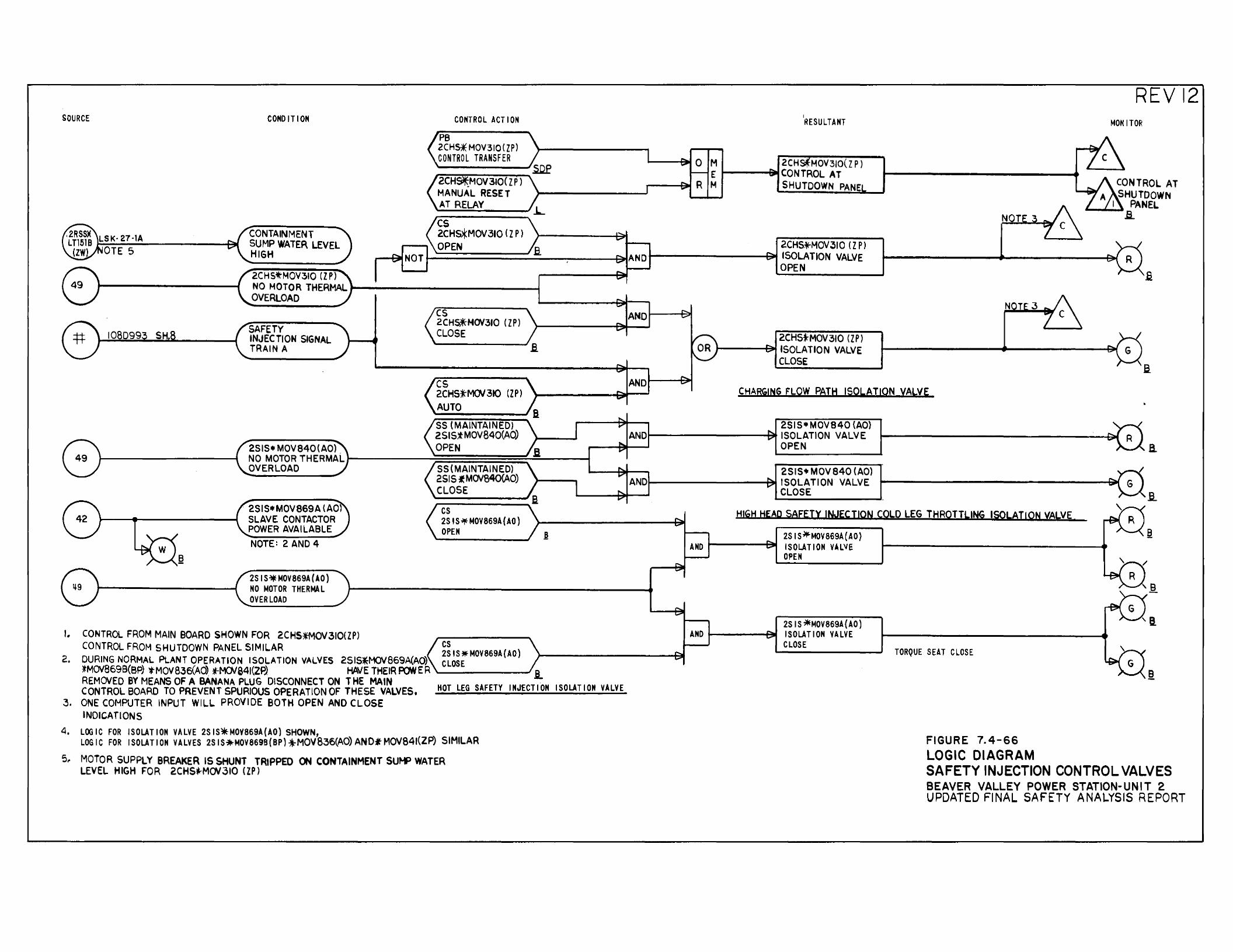
SOURCE
LSI<· 27·1A OTE 5
CONDITION
CONTAINMENT SUMP WATER LEVEL HIGH
2CHSt"MOV310 (Z Pl
CONTROL ACT I ON
PB 2CH~ MOV310 ( ZP) CONTROL TRANSFER
cs 2CH~MOV310 ( Z P) OPEN
NO MOTOR THERMAL t--------------1 OVERLOAD
108099 SAFETY INJECTION SIGNAL TRAIN A
cs 2CHS*HOV310 ( ZP) CLOSE
cs 2CHS*M0/310 (ZP) AUTO SS (MAINTAINED) 2SIS*MOV840(AO)
2515• MOV840(AO} . OPEN NOMOTORTHERMALr---------~=:=:=::=:=::~~--__, OVERLOAD SS{MAINTAINED)
2SIS•MOV869A (AO) SLAVE CONTACTOR POWER AVAILABLE NOTE: 2 AND 4
25 IS'*MOV869A(AO) NO MOTOR THERMAL OVER LOAD
J. CONTROL FROM MAIN BOARD SHOWN FOR 2CHS*MOV310(ZP)
2515 iMOV84Q(AO) CLOSE
cs 2S IS..l!fMOV869A(AO) OPEN
CONTROL FROM SHUTDOWN PANEL SIMILAR ~~IS•Mova6sA(AO} 2. DURING NORMAL PLANT OPERATION ISOLATION VALVES 251SlMOV869A(AO) CLOSE
~MOV869B(BP) 'tMOV836(AO) *-M(}JS41(ZP) HAVE THEIR POWER'---------' REMOVED BY MEANS OF A BANANA PLUG DISCONNECT ON THE MAIN CONTROL BOARD TO PREVENT SPURIOUS OPERATION OF THESE VALVES,
3. ONE COMPUTER INPUT WILL PROVIDE BOTH OPEN AND CLOSE INDICATIONS
HOT LEG SAFETY INJECTI.ON ISOLATION VALVE
4. LOGIC FOR ISOLATION VALVE 2S IS*MOVB69A(AO) SHOWN, LOGIC FOR ISOLATION VALVES 2SIS*MOV869B(BP)*MOV836(AO)AND*MOV841(ZP) SIMILAR
5.. MOTOR SUPPLY BREAKER IS SHUNT TRIPPED ON CONTAINMENT SUH? WATER LEVEL HIGH FOR 2CHStrMOV310 (ZP)
I
RESULTANT
M 2CH MOV310( Z P) E 1-----BIIICONTROL AT M SHUTDOWN PANE
2CHS*MOV 310 ( Z P) t--------~;..t ISOLATION VALVE
OPEN
2CHStMOV310 (ZP) t-----f3111 ISOLATION VALVE
CLOSE
REV 12 MONITOR
NOT
CHARGING FLOW PATH ISOLATION VALVE
2SIS•MOV840 {AO} ANDI-----------1'* ISOLATION VALVE
OPEN
2515+ MOV 840 (AO) ANOI-------------A~~~ ISOLATION VALVE
CLOSE
a
HIGH HEAP SAFETY INJECTION COLO LEG THROTTLING ISOLATION VALVE
2SIS~MOV869A(AO) AND ~-----+~ ISOLATION VALVE
OPEN
2S IS *MOV869A{AO) AND .,...._ __ --+o311 ISOLATION VALVE
CLOSE TORQUE SEAT CLOSE
FIGURE 7.4-66 LOGIC DIAGRAM SAFETY INJECTION CONTROL VALVES BEAVER VALLEY POWER STATION-UNIT 2 UPDATED FINAL SAFETY ANALYSIS REPORT
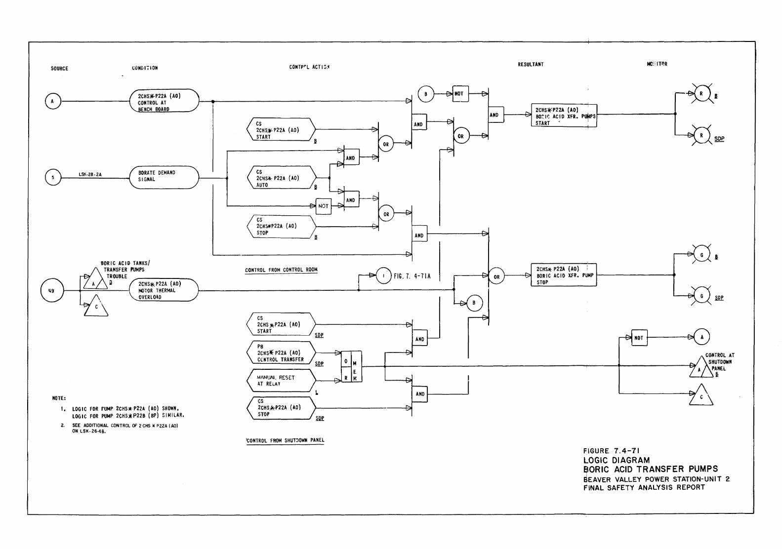
SOURCE CONDIIION
8-----4" 2CHS*-P22A (AO) CONTROL AT
EMCH BOARD
LSK-Z8-2A BORATE t>EMANO SIGNAL
BORIC ACID TANKS/ TRANSFER PUMPS
TROUBLE .a 2CH~ P22A ( AO)
~---+-=~===!:..____~ MOTOR THERMAL OVERLO~[)
NOTE:
I. LOGIC FOR rUio4P 2CHS * P22~ ( ~0) SHOWN, LOGIC FOR PUMP 2CHS.*P22B (BP) SIMILAR.
2. SEE ADDITIONAL CONTROL OF 2 CHS II P22A (AO) ON LS K- 26-6 8.
CONTP"L ACT I :j_i
cs 2CH S)'C P22A ( AO) START
cs 2CH~ P22A {AD) AUTO
cs 2CH&*P22A (AD) STOP
CONTROL FROM CONTROL ROOM
cs 2CHS *P22A ( AO) START
PB 2CHS* P22A (AO) CCNTROL TRANSFER
MANUAL RESET A.T RELA l
L
< ~~HS.*-P22A (AO) ) STOP .__________.., ill
tONTROL FROM SHUT~OWN PANEL
FIG. 7. 4-7\A
M
RESULTANT
2CHS¥P22A (AO) . 1----P31 BOr:l~ ACID XFR. Puj.ws~-------__.
START :
2CHS* P22A { AO) : BORIC ACID XfR. PUMP 1-------------t STOP
FIGURE 7.4-71 LOGIC DIAGRAM BORIC ACID TRANSFER PUMPS SEAVER VALLEY POWER STATION-UNIT 2 FINAL SAFETY ANALYSIS REPORT
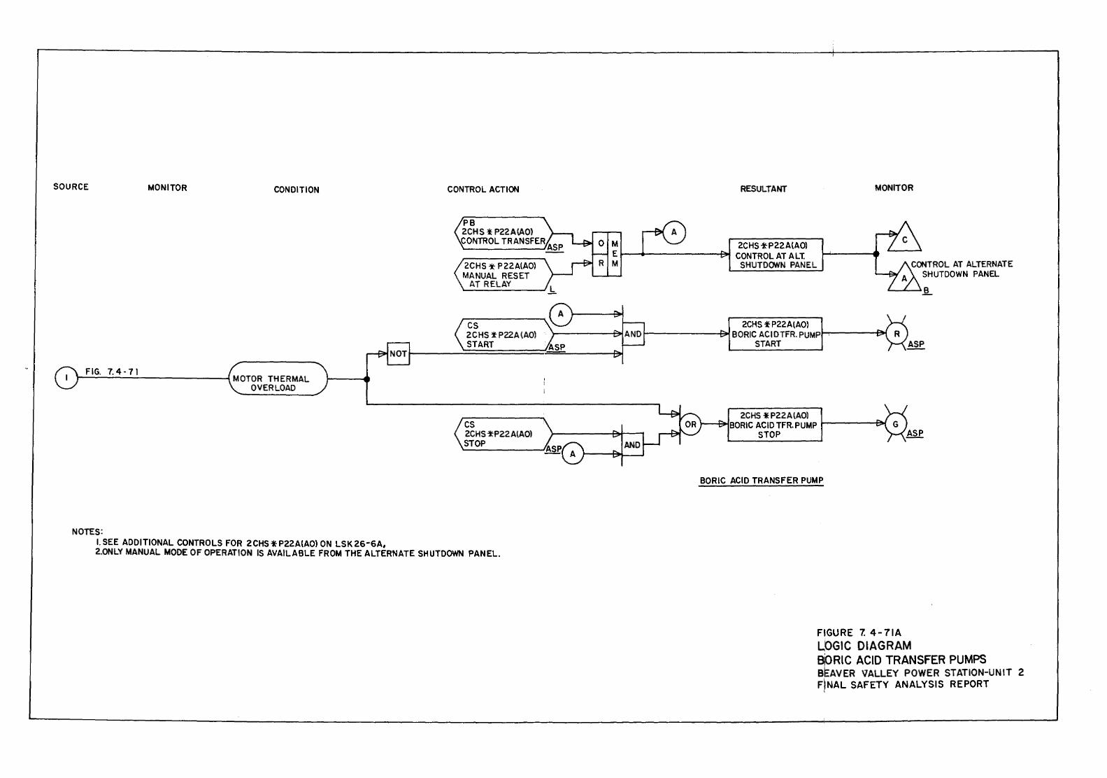
SOURCE MONITOR CONDITION
FIG. 7.4-71 '1-------------1 MOTOR THERMAL OVERLOAD
NOTES: I. SEE ADDITIONAL CONTROLS FOR 2CHS t: P22AtAO) ON LSK 26-SA,
CONTROL ACTION
2CHS -t- P22A(A0l MANUAL RESET
AT RELAY
cs 2 C HS t: P22A (AOl START
cs 2CHS -t-P22 A lAO) STOP
2.0NLY MANUAL MODE OF OPERATION IS AVAILABLE FROM THE ALTERNATE SHUTDOWN PANEL.
RESULTANT
2CHS -t;P22A{A0) 1o--__.,.-----~ CONTROL AT ALT.
SHUTDOWN PANEL
MONITOR
2CHS * P22A{A0l t--------E:;..t BORIC ACI DTFR. PUMPI--r----~
START
2CHS *P22AlAOl )---&!BORIC ACID TFR. PUMP I------13Jt.l
STOP
BORIC ACID TRANSFER PUMP
FIGURE 7. 4-71A LOGIC DIAGRAM BiORIC ACID TRANSFER PUMPS BEAVER VALLEY POWER STATION-UNIT 2 FINAL SAFETY ANALYSIS REPORT
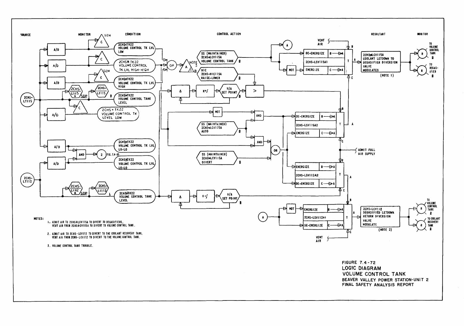
SOURCE MONITOR CONDITION CONTROL ACTIO~
2CHS(TK22 VOLUME CONTROL TK LVL A/0 LOW SS {NAINTAINEO)
2CHS4LCYIISA 2CHS* TK22 VOLUME CONTROL TANK
A/D VOLUME CONTROL TK. LVL HIGH· H! GH HIC
2CHS-HICIISA 2CH~K22 RAISE-LOWER
A/D VOLUME CONTROL TK LVL HIGH
K+J > 2CHOOK22 VOLUME CONTROL TANK LEVEL
2CHS * TK22 A/o VOLUME CONTROL Tl< ,
LEVEL LOW SS (MAINTl..INED) 2CHS-..LCV liSA AUTO
2CHS)(TK22 VOLUME CONTROL TK LVL LO-LO
SS (MAINTAINED) 2CHS~CY liSA DIVERT
2CH3jl"K22 VOLUME CONTROL TANK A K+j LEVEL
HOlES: I • UIIT AIR TO 2C HS HCV 115A TO DIVERT TO DWSI FIE RS,
YEll AIR FROII 2CHHCYI15A TO DIVERT TO VOlUIIE CONTROl TUK.
2 . A»ll IT AIR TO 2C N S- LCY 112 TO DIVERT TO THE COOLAIT RECOVEU TAU, VEIT AIR FRO II 2CHS-l CY 112 Til DIVE U TO THE VOLUIIE COlTROL Tm.
3. VOLUIIE COIITROL TAll« TROUBLE.
VENT AIR
DE-ENERGIZE
2CHS-LSVI15AI
ENERGIZE
DE-ENERGIZE
2CHS-LSVIISA2 T
ENERGIZE
2CHS-LSV112A2 T
DE-ENERGIZE
2CHS-LSVII2AI
DE-ENERGIZE
VEIH AIR
RESULT.U T
B
2CH5;11LCVII5A COOLANT LETDOWN TO T DEGASifiER DIVERSION VALVE MODULATES
c {NOTE I)
B
A
ADNIT FULL AIR SUPPLY
A
c
B
2CHS-LCY I 12 A DEGASIFIED LETDOWN
T RETURN DIVERSION VALVE MODULATE
c (NOTE 2)
FIGURE 7. 4-72 LOGIC DIAGRAM VQLUME CONTROL TANK
IIOIITOR
TO VOLUII£ CONTROL TAlK
.B TO Of CAS-If lEI .I
TO VOLUIIE comot TAU
s: TO COOL AU RECOVERY TAMI B
BEAVER VALLEY POWER STATION-UNIT 2 FINAL SAFETY ANALYSIS REPORT
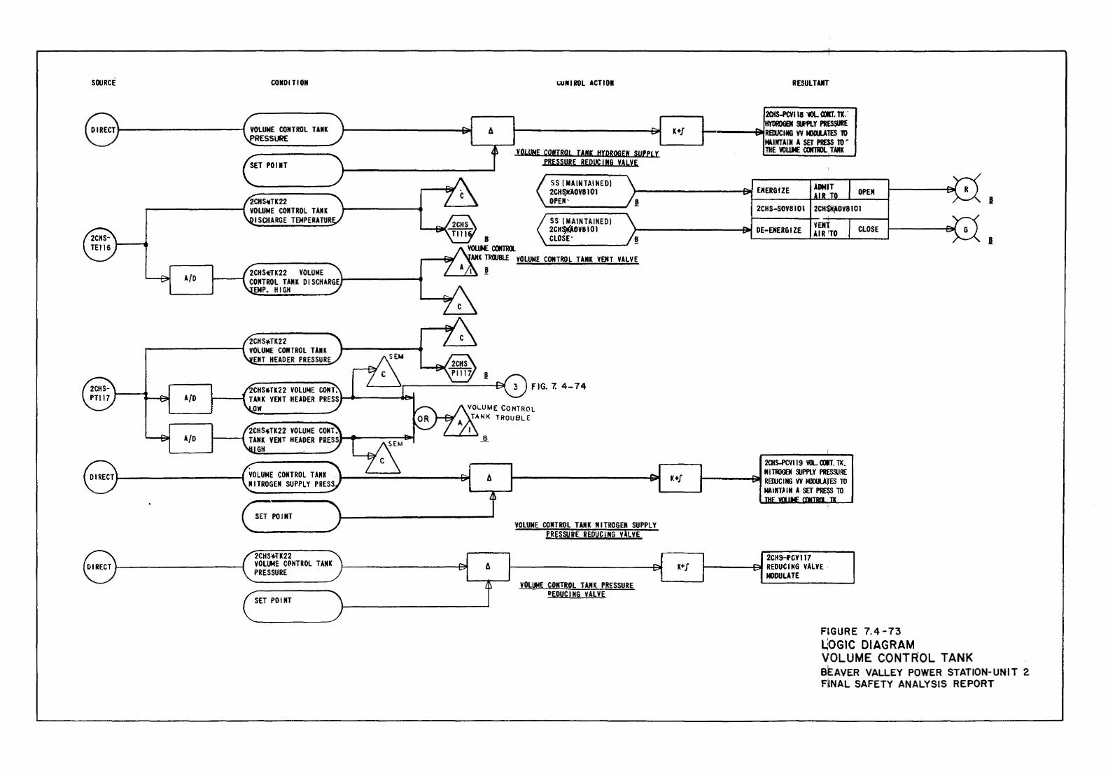
SOURCE CONDITION
~----------f VOLUME CONTROL TAIIK PRESSURE
2CHSI!ITK22 r----------4 VOLUME COIITROL TAIIK I SCHARGE TEMPERATUR
A/0 2CHS~TK22 VOLUME ---f CONTROL TANK 0 l SCHARGE 1--------4 ENP. HIGH
2CHS*TK22 VOLUME CONTROL TAIIK
ElfT HEADER PRESSURE
2CHS*TK22 VOLUME CONT. A/D TANK VENT HEADER PRESS
OW
2CHS*TK22 VOLUME CONT. A/D TANK VENT HEADER PRESS
GH
VOLUME CONTROL TANK NITROGEN SUPPLY PRESS
SET POINT
2CHS~K22 VOLUME CPNTROL TANK PRESSURE
SET POl NT
WRIROL ACTIOII
VOL!JHE COHIBOL TANK H(QBOGEN SUPPLY PRESSURE REPutiNG VALVE
SS {MAIN TAl NED) 2CH~OV8101 OPEN·
SS (MAIN TAlNEO) 2CH~OV8101 CLOSE'
VOLUME CONTROL TANK VENT VALVE
FIG. 7. 4-74
VOLUME CONTROL T AJI K NITROGEN SUPPLY PRESSURE REDUCING ViLVE
VOLUME CONTROL TANK PRESSURE I!EDUCING VALVE
K+f
K+f
K+J
RESULTANT
201S-PCVII8 WL. aJIIT. Tl .. IMlROOEN UPLY PRESSURE
t-·----9fRBlJCUI6 VV tm.UTES 10 MUirTAIIf A SET PRESS 10 ~ lliE WLLME <XIfTII)l.. T Nil
ENERGIZE
2CHS-50V8101
DE-ENERGIZE YENl AIR'TO
201S-PCV119 WL.aJIT. TK. N I TIIIGEII &IPPLY PRESSURE REDJCING VV MOOLATES TO NAIIIT-'IN A SET PRE$S TO
2CHHCV117 REDUCING VALVE MODULATE
OPEN
CLOSE
FIGURE 7.4-73 LOGIC DIAGRAM VOLUME CONTROL TANK
I
I
BEAVER VALLEY POWER STATION-UNIT 2 FINAL SAFETY ANALYSIS REPORT
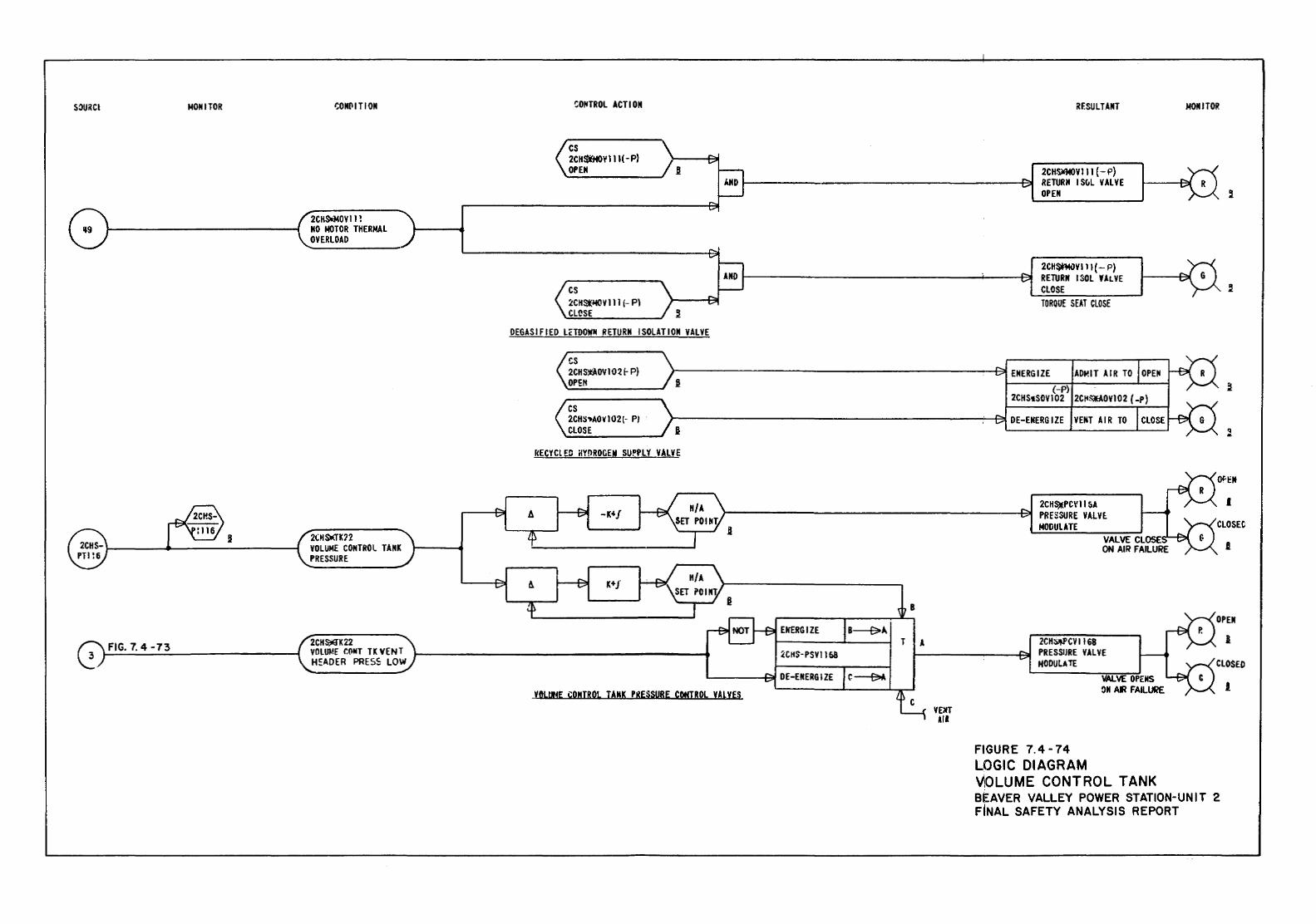
S~RCI MONITOR
FIG. 7. 4 -73
t;ONPITION
2CHOOIOYII! NO MOTOR THERMAL OVERLOAD
2CHs-a-K22 VOLUME CONTROL TANK PRESSURE
2CHWK22 VOLUME CONT TK VENT H~AOER PRESS LOW
t;OIHROL ACTION
cs 2CH$tHO\' Ill(- P} OPEN
cs :£CH~VIII (-Pl CLCSE
RESULTANT
2CH0040Vlll (- P) RETURN IS~L VALVE OPEN
2CH$*Mi)Yill (- P) RETURN ISOL 'ALVE CLOSE TORGUE SEAT CLOSE
DEGASIFIED LcTDOW" RETURN ISOLATION VALVE
A
cs 2CHmOVIO~ 1- P) OPEtl
cs 2CH~~AOV102(- P/ CLOSE
>------------------------811 ENERGIZE ~----~,_~~~------~--~
2CHS•SOVI02 2C~S¥AOVI02 (-P)
>-------------------------'-f~ DE-EHERG IZE VENT AIR TO
kECYClEC ~YOROGEN SU~PLY VALVE
-K"f
K+J
2CHS:.:PC\'li~A PRESSURE VALVE. MODULATE
MONITOR
q ..
I
OPEN ElfERGIZE
2CHS-PSVII53
YftLUHE CONTROL TANK PRESSURE COHJROL VAlVES WIT All
2CH:)lt.PCV 1168 PRESSIJRE VALVE MODULATE
FIGURE 7. 4 -74 LOGIC DIAGRAM V!OLUME CONTROL TANK BEAVER VALLEY POWER STATION-UNIT 2 FINAL SAFETY ANALYSIS REPORT
I
.l
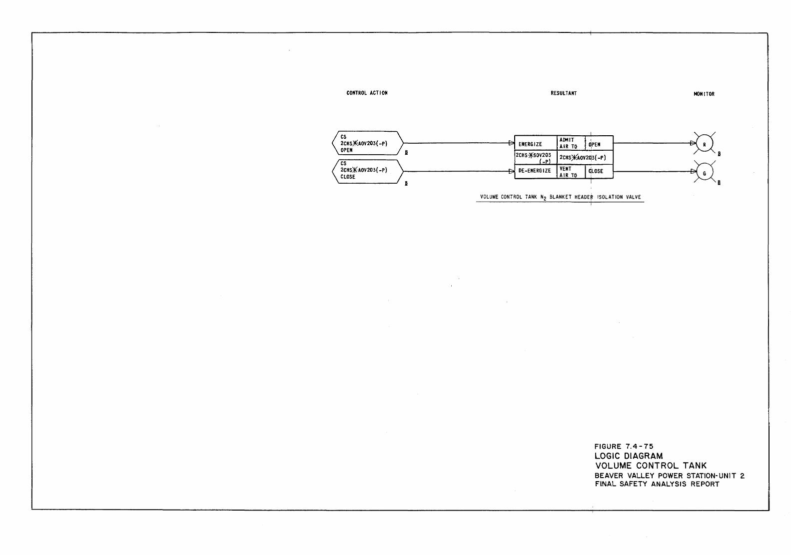
CONTROL ACTION
cs 2CHS~AOV203(-P) OPEN fl
cs 2CHS~AOV203{-P) CLOSE
B
RESULTANT NONITOR
I
" ADMIT I ~PEN ..... ~ ENERGIZE AIR TO ... R
2CHS~OV203 fl 2CHS*AOV2Q3{ -P) ( -Pl ... DE-ENERGIZE VENT I ~LOSE " v ..... G AIR TO
I B
VOLUME CONTROL TANK N2 BLANKET HEADE~ I SOL AT ION VALVE I
FIGURE 7.4-75 LOGIC DIAGRAM VOLUME CONTROL TANK BEAVER VALLEY POWER STATION-UNIT 2 FINAL SAFETY ANALYSIS REPORT
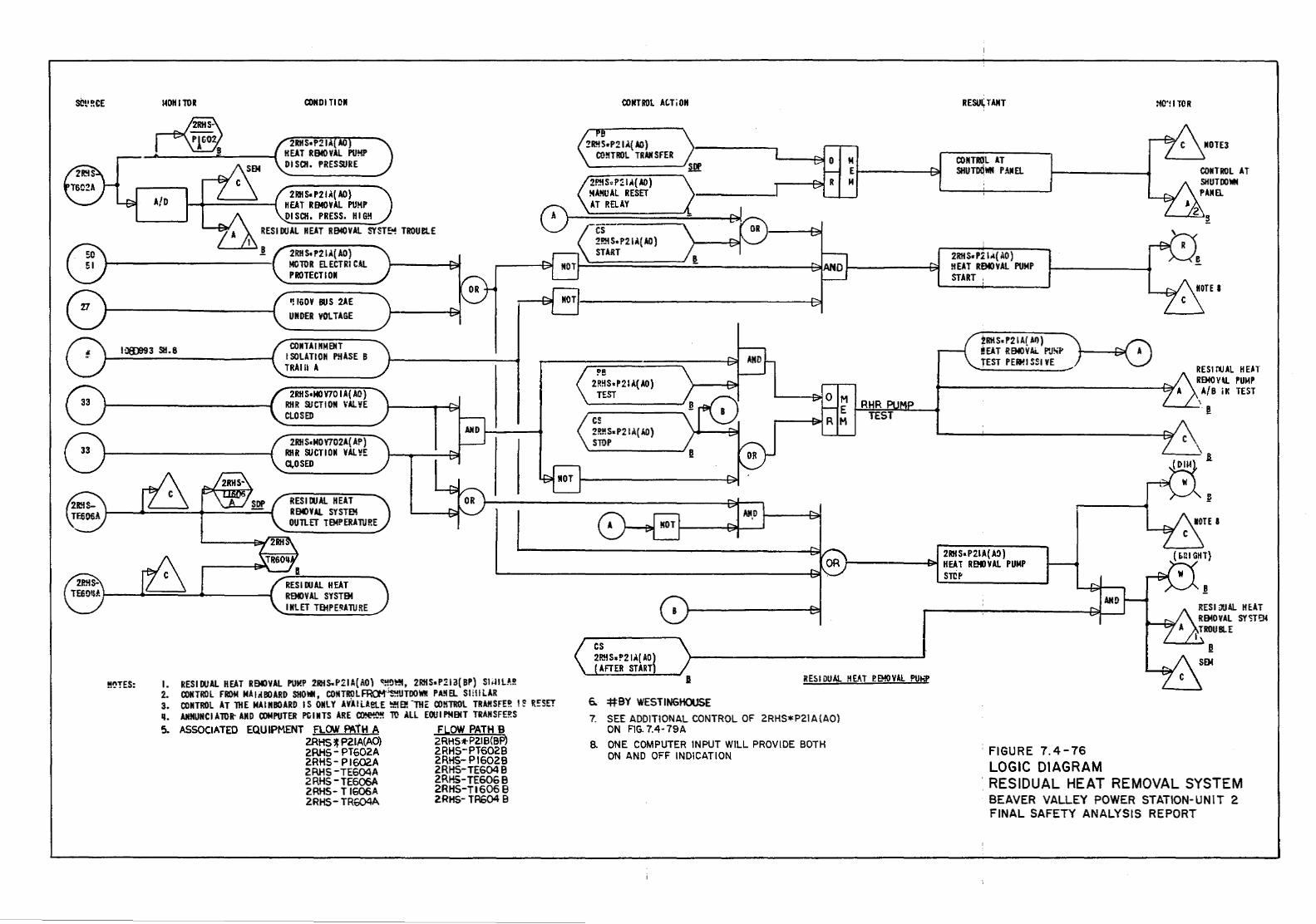
SCt1 ~CE
Q) 51
140tlllOR COMO! TIOII
r-®. 8
2RKS•P21.1( AD) A/0 HEAT REMOVAL PUMP 0 DISCH. PRESS. HIGM
2RHS.P21.1{ AO) MOTOR ELECTRICAL PROTECT lOll
'! 160V BUS 2AE ~ UNDER VOLTAGE
I :18)99 3 Sll. 8 COIITA I liM ENT I SOLATIOII PHASE B
!!IJTES:
TRAIII A
2RHS•MOV70 lA( AO) RKR 3.1CTIOM \'AI..YE CLOSED
2RHS•MO V702A( AP) RHR SUCTION YALYE Q.OSED
RESIDUAl HEAT ROOVAL. SYSTEM OUTLET TEMPERATURE
RES\ OOAl HEAT REMOVAL SYSTEM INLET TEMPE~ATURE
I. RES I DUAL HEAT ROO VAL PUMP 2RHS.P21 A{ AD) ~!!!ll'!t, 2RHS•P11 a{ BP) Sli-lll.A.!! 2. CONTROL FROM MAiiUIOARD SHO*, CONTR!)l~UTD0'1111 PA!IEL SIHILAR 3. CONTROL AT THE MAl II BOARD IS DillY AVliLAet..E ~E!! -THt: CO!!TROL TRAHSF!~ I~ R.~SET q, AMMUNC I A TOR- AltO COMPUTER Pli I II TS ARE ~ 'ro .\ll EOU I PMENT TRAil SFE!!S 5. ASSOCIATED EQUIPMENT FLCM' PATH A FLOW PATH B
2RHS~P21A(AO) 2RHS*P2.1B(BP) 2RHS-PT602A 2RHS-PT6028 2RHS- PI602A 2RHS- P\6029 2RHS -TE604A ZRHS-TE604 9 2RHS-TE606A 2RHS-TE606B 2RHS- T 1606A 2RHS-TI606 B 2RHS- TR604A 2.RHS- TR604 9
OONTRDL At;Ti 011
2P.!IS~P~ lA( AD) !4A..'IIJAL RESET
\AT RELAY
cs 2!!!1S•P211l{ AO) START
!'B 2!!!!S•P21J.( AD)
TEST
cs 2!!MS• P21 A( ItO) STOP
cs 2R!i s. !'21.1( AD)
AFTER START)
l!!f
RESU~TAIIT
M OOIITROL AT E SHUTDQWN PAIIEL M
2RtiS•P~ \"( AO) HEAT REMOVAl PUMP START ,
'
!RKS•P21A( AI)) !!EAT REMOVAL P'JSI' TEST PEit!ISSIVE
2RH Sa P21A(...,) 1--------1:~ HEAT ROOVAL PUMP
STCP
MC'll TOR
IIOTE3
~
RES I ruAL HE.6T REMOV\1. PUMP A/8 itc TEST
-~
\
I
'a
~
§
RES I iXJ.\1. HE.AT REMOVAL SY<;Te.t TROUBLE
B RES I DUAL !!EAT P.e«<VAL PU!-iP
6. #BY WESTINGHOUSE 7. SEE ADDITIONAL CONTROL OF 2RHS*P21A{A0}
ON FIG. 7.4-79A a ONE COMPUTER INPUT WILL PROVIDE BOTH
ON AND OFF INDICATION :FIGURE 7.4-76 LOGIC DIAGRAM
. RESIDUAL HEAT REMOVAL SYSTEM BEAVER VALLEY POWER STATION-UNIT 2 FINAL SAFETY ANALYSIS REPORT
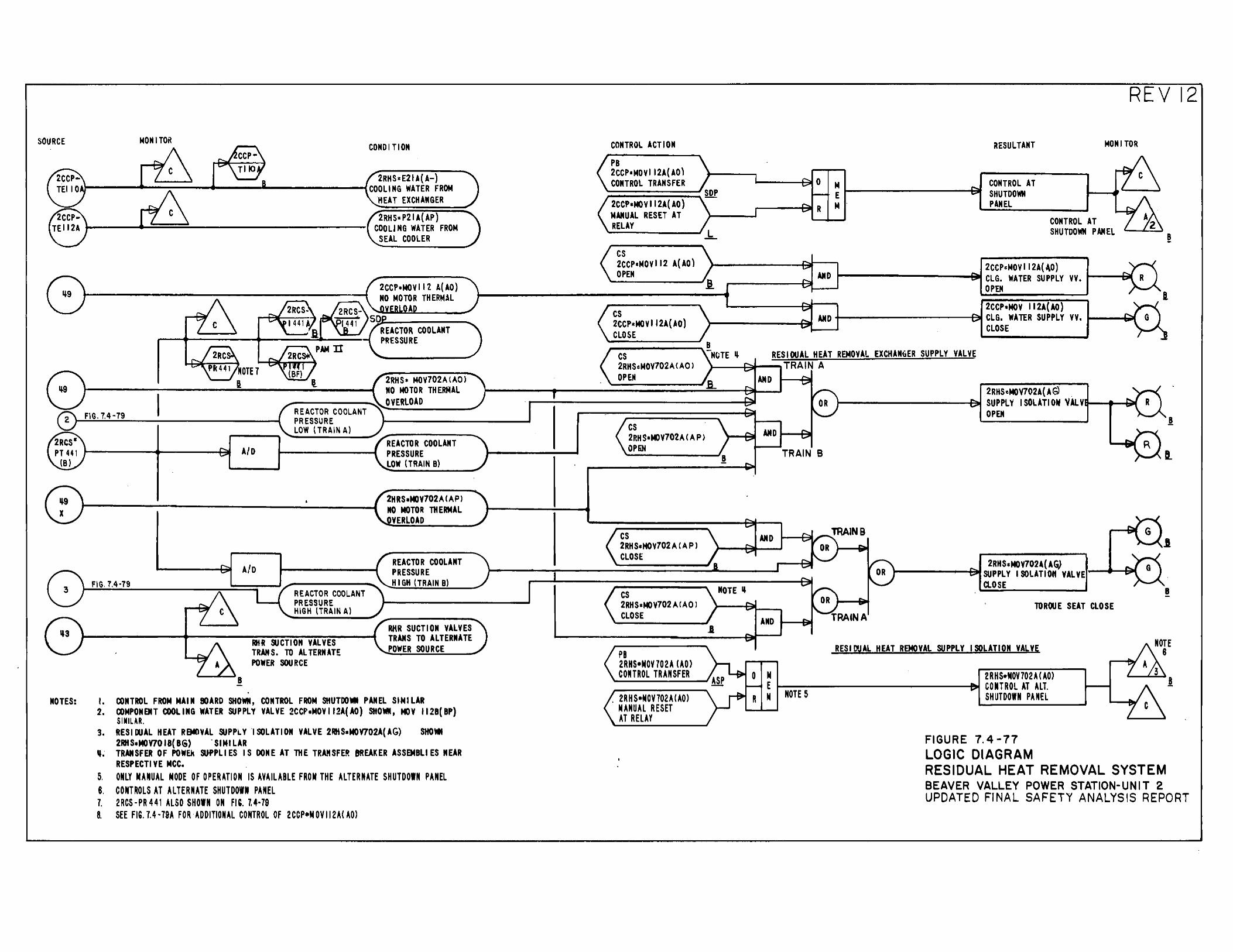
SOURCE
MOTES:
MONITOR
FIG. 7.4·79
B
A/D
REACTOR COOLANT PRESSURE LOW (TRAIN A)
REACTOR COOLANT PRESSURE HIGH (TRAIN A)
RHR SUCTIO" VALVES TRANS. TO ALTERNATE POWER SOURCE
CONDITION
2CCP•MOVII~ A(AO) NO MOTOR THERMAL
A
2RHS• MOV702A{A0l NO MOTOR THERMAL OVERLOAD
REACTOR COOLANT PRESSURE LOW (TRAIN B)
2HRS•t«JV702A (AP l NO MOTOR THERMAL
YERLOAD
REACTOR COOLANT PRESSURE HIGH (TRAIN B)
RHR SUCTION VALVES TRANS TO ALTERNATE POWER SOURCE
I. CONTROL FROM MAIN BOARD SHOWN, CONTROL FROM SHUTDOMI PANEL SIMILAR 2. COMPONEJIT COOLING WATER SUPPLY VALVE 2CCP•MOVI J2A(AO} SHOWN, HOY t12B(BP)
SIMILAR. 3. RESIWAL HEAT REMOVAL SUPPlY "lSOLATION VALVE 2RHS•MOV702A(AG) SHO.e
2RHS•MOY701B(BG) 'SIMILAR ,,. TRANSFER OF POWEk SU-PPLIES IS DONE AT lHE TRAttSFER Bf!EAKER ASSEMBLIES NEAR
RESPECT! VE MCC. 5. ONLY MANUAL NODE OF OPERATION IS AVAILABLE FROM THE ALTERNATE SHUTDOWN PANEL 8. CONTROLS AT ALTERNATE SHUTDOWN PANEL 7. 2RCS·PR441 ALSO SHOWN ON FIG. 7.4·79 8. SEE FIG. 7.4·79A FOR·ADDITIONAL CONTROL OF 2CCP•NOVII2A(A0)
CONTROL ACTION
PB 2CCP•MOYI 12A(AO) CONTROL TRANSFER
2CCP•MOVII2A(AO) MANUAL RESET AT RELAY
cs 2CCP•MOVII2 A(AO) OPEN
cs 2CCP•MOVII2A(AO) CLOSE
cs 2RHS~MOV702A<AOl
OPEN
cs 2RHS•t«JV702A CAP> OPEN
cs 2RH S•HOV702 A (A P) CLOSE
cs 2RH S•t«) '1702 A (A 0 l CLOSE
PB 2RHS•NOY702A (AO) CONTROL TRANSFER
. 2RHS•NOV702A(A0) NANUAL RESET AT RELAY
REVI2
Mt----------~ E M
itESULTANT
CONTROL AT SHUTDOWN PANEL
MONITOR
CONTROL AT SHUTDOWN PANEL
2CCP~MOVI 12A(40) ,..-----~ AMD ~---------+:a.i CLG. WATER SUPPLY VV • ..,_._.....,.
OPEN
2CCP•MOV 112A(AO) l---------'=::.. AND +------------f==!lll CLG. WATER SUPPLY VV ....... --t:.iiill
CLOSE
RESIDUAL HEAT REMOVAL EXCHANGER SUPPLY VALVE l----+;;;t---..TRA IN A
AND
TRAIN B
2RHSeNOV702A(AG'l r-----------f~ SUPPLY ISOLATION VlLVtt---.~~
OPEN
2RHS~MOV702-(A~ SUPPLY ISOLATIOft VALVE Cl.O SE
TOROUE SEAT CLOSE
RESI~JAL HEAT REMOVAL SUPPLY ISOLATION VALVE
N 2RHS•MOV702A(A0) ~ 1--NO-TE-5-----------....fi!J.I CONTROL AT ALT. "' SHUTDOWN PANEL
FIGURE 7. 4-77 LOGIC DIAGRAM
I
B
RESIDUAL HEAT REMOVAL SYSTEM BEAVER VALLEY POWER STATION~ UNIT 2 UPDATED FJNAL SAFETY ANALYSIS REPORT
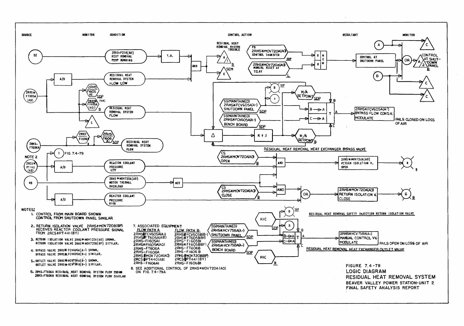
SOURCE MOll I TOR COIIDITI 011 COIIiROL ACTIOII RESULT AliT MOll I TOR
PB
2~S•P21A(AO) H~T RBI>VAL f'l~~!" RIJIIIIING
RES I DUAL HEAT RB«<VAL SYSTel
TROUBLE 2RHSM-MOV720A(AOi>--..., '!.D. CONTROl 1 tCAII SFEk '--~~
A/D RES !DUAL HEAT REMOVAL SYSTEM ~LOW LOW
RESIDUAL HEAT REMOVAL SYSTEM FLOW
-~ 2RHS*MOV 7ZOA(.A.O) MANUAL RESET AT TELAY
SS(MAINTAINED) 2RHS*FCV605A(A-) )--oii----
SHUTDOtYN R\NEL .sop SS(MAINTAI NED) 2RHS*FCV605A(A -1 BENCH BOARD
Kt..S
B
2RHS* FCV605A(A-t-----l T ~A.l.---£~BYPASS·FLOW COtH,V,
._M_OD_UL.;...A_;T....::E~-----' FAILS CLOSED ON LOSS OF AIR
RESIDUAL HEAT ROOVAL SYSTEM FLOW R~SIDUAL HEAT REMOVAL HEAT EXCHANGER B't'PASS VALVE
A/D REACTOR COOLANT I'RESSURE
cs 2RHSJIE-MC1/720ACAC9 OPEN
L~~
2RHS i!IMOV720A(AO) MOTOR THERMAL OVERLOAD
A/0 RU.CTOR COOLANT PRES3URE !!1~-
NGTEs: I. CONTROL FROM MAIN BOARD SHOWN
CONTROL FROM SHUTDOWN PANEL SIMILAR
2, RETURN ISOLATION VALVE 2RHSifMOV720B(BPl RECI!IVES REACTOP. COOLANT PRESSURE SIGNAL FROM 2RCS*PT441 (BY)
3, RETURH ISOLATION VALVE 2RHS'!fr MOVIZ::OA( AO) SHOWN. RETURN I SOLATION VALVE 2RHS* MOV7:0B( BP) S WI LAR.
4, BYPASS VALVE 2RHS* FCV605A (A-\ SHOWN, BYPASS VALVE 2RHS~FCVEOSB(B-) SIMILAR.
5 1 OUTLET VALVE 2RHS*HCV15BA(~-) SHOWN, OUTLET VALVE 2RHS*- HCY758 B{ 8-) S Ull LAR.
6, 2R'IS-FT606A RESIDUAL _HEAT ROOYAL SYSTEM FlO~ S!iOVC 2RHS-FT606B RESIDUAL HEAT ROO VAl SYSTEM FLOW SI!HLAR
1. ASSOCIATED EQUIPMENT SS(MAINTAINED) A.OW PATH A FLOW PATH 8 2RHS*HCV758A(A-)
2RHstfCV605A{A-) 2RHS.FCV605B<B-) SHUTornJN PA 2RH~T605A(A Ef} 2RHSfFT605BtB'O ;;;:~~~~:::::: 2 RH5-FI605AI 2R HS- F 160581 SS(MAINTAINED 2R HS*F16Q5A(AQ l 2RHS* F I 605 B(BF) 2RHS* HCV758A{A-) 2RHS-FTG06A 2RHS- FT606B BENC 2RHS-FI606A 2RHS-fl606 B H BOARD 2RHS IMov 1 zoAl"AO) zRHstNov 720B{BP) 2RCSfPT 440(ABl 2RCSfPT44 I (BY l 2RHS- F1606AI 2RHS- F 160bBI
8. SEE ADDITIONAL CONTROL OF 2RHS*MOV720A(AO) ON FIG. 7.4-79A
2~H ~MOV72~A(AO) R~TU~N ISOL~TIUN V. OPEN
2RHS*MOV 720A{AO) 1--------f::MRETURN ISOLATION V, t------1~
CLOSE
RESIDUAL HEAT REMOVAL SAFFfY lhJECT!OM RETURN ISOLATION VALVE
2RHS* HCV 758A{A-) r-:---------&-1 MA"UAL CONTROL VV,
MOOuLATE FAILS OPEN ON LOSS OF AIR RESIDUAL HEAT REMOVAL HI=" AI ~="XCHANG~B QWl.ET VALVE
FIGURE 7. 4-78 LOGIC DIAGRAM RESIDUAL HEAT REMOVAL SYSTEM BEAVER VALLEY POWER STATION-UNIT 2 FINAL SAFETY ANALYSIS REPORT
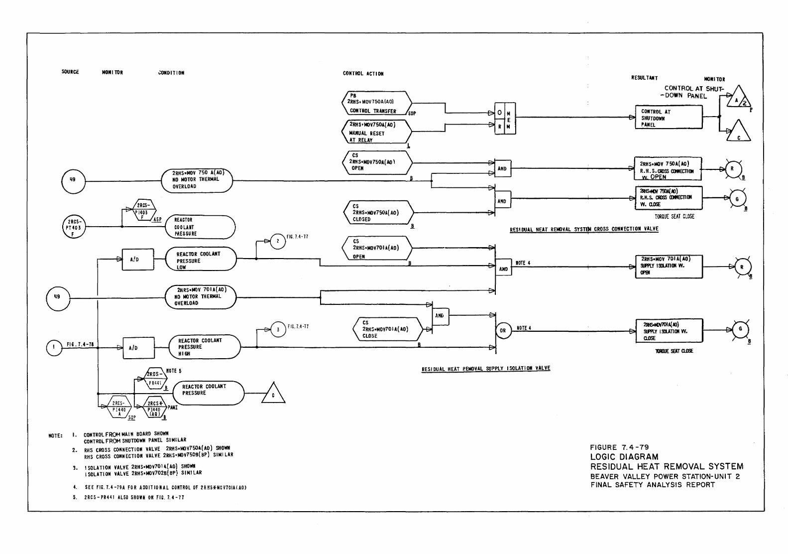
SOURCE MOM I TOR .;oMD1TION
2RHS•MOV 750 A(AO NO MOTOR THERMAL OVERLOAD
REACTOR COOLAKT PRESSURE
MOTE: I . CONTROL FROM MAIM BOARD SHOWN CONTROL FROM SHUTDOWN PAMEL S I Ml LAR
2. RHS CROSS COMMECTIOM VALVE 2RHS•MOV7SOA(AO) SHOWN RHS CROSS CONNECTION VALVE 2RHS•MOV750B(BP) SIMILAR
3. ISOLATION VALVE 2RHS•MOV701~(AO) SHOWN ISOLATION VALVE 2RHS•MOV702B(BP} SIMILAR
4. SEEm. 7.4-79A fOR A!JDITIONAL COMTROL Of 2RHSHOV701AIAOJ
5. 2RCS- PR441 ALSO SHOlfl! Oil FIG. 7. 4-77
CONTROL ACT1 ON
PB 2RH S• MOV750A (AO}
CONTROL TRANSFER
2RHS•MOV750A{ AO} NI.MUAL RESET AT RELAY
cs 2RHS•NOV750A{AO l
OPEN
RESUL TAIT MONITOR CONTROL AT SHUT-
-DOWN PANEL
CONTROL AT SHUTDOWN PANEL
2RHS•MOV 750A(AO) R • H • S • allSS aiiiECTI (II
OP N
2RIS.MW 73¥( /(')) ~---------+------e-1 R.H.s. aoss CDMB:Tllll w. Q..OSE
TOROUE SEAT Cl.GSE
RESIDUAL HEAT REMOVAL SYSTEM CROSS COMNECTIOM VALVE
IOTE 4 2RHS•MOY 701 A AO ~;;.;.;;...~------...;-----~ 9FPlY ISI..A.TION W.
NOTE 4
RESIDUAL HEAT P.EMOVAL SUPPLY ISOLATION VALVE
CP9I
2111SaMW7UI A( lfJ) 9J'PLY I SI..A.TION YY. Ci.DSE
FIGURE 7. 4-79 LOGIC DIAGRAM RESIDUAL HEAT REMOVAL SYSTEM BEAVER VALLEY POWER STATION-UNIT 2 FINAL SAFETY ANALYSIS REPORT
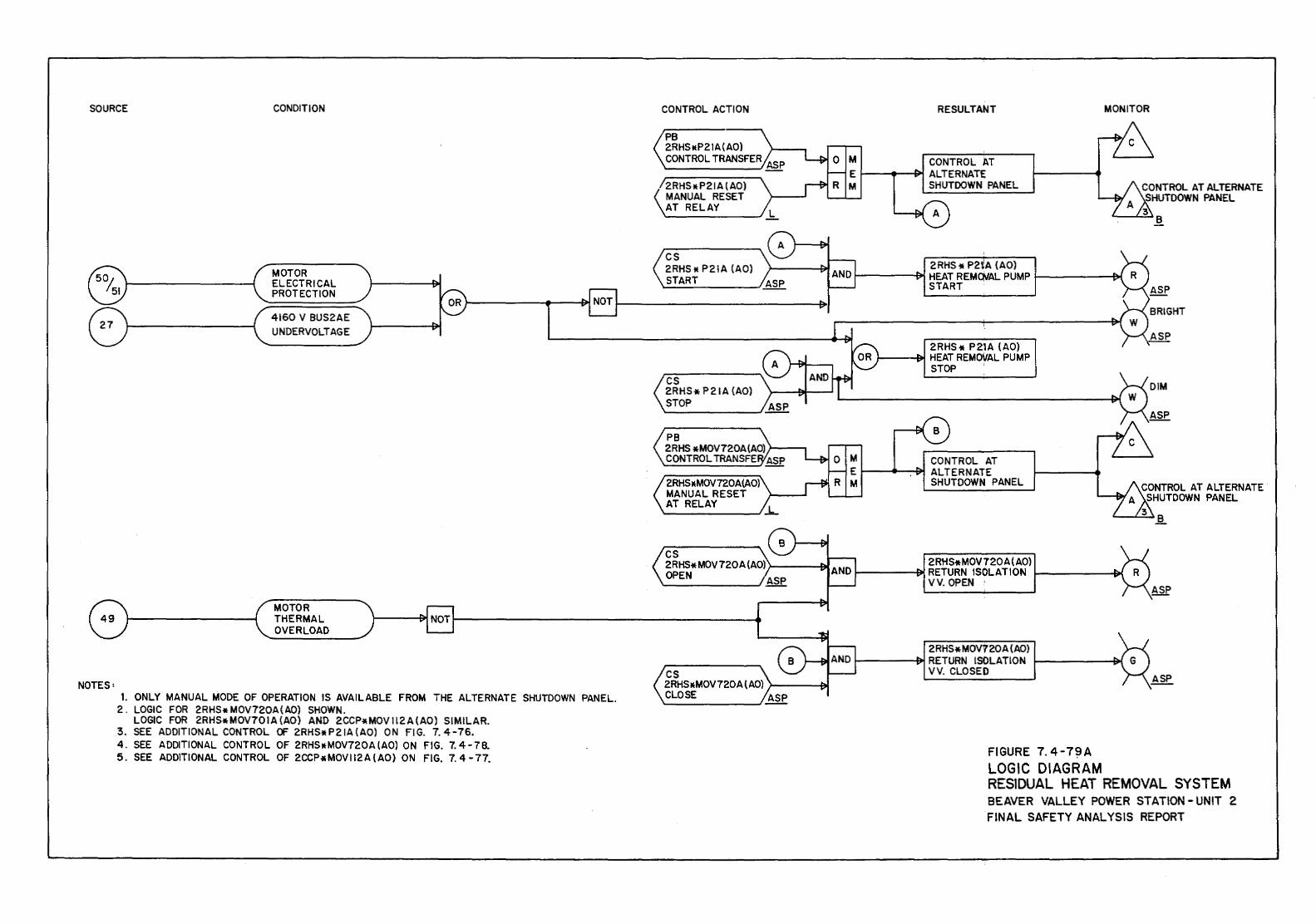
SOURCE CONDITION
NOTES:
MOTOR ELECTRICAL PROTECTION
4160 V BUS2AE UNDERVOLTAGE
MOTOR THERMAL OVERLOAD
1. ONLY MANUAL MODE OF OPERATION IS AVAILABLE FROM THE ALTERNATE SHUTDOWN PANEL. 2 . LOGIC FOR 2R HS * M OV720A { AO) SHOWN.
LOGIC FOR 2RHSttMOV701A(AO) AND 2CCPttMOV112A{AO) SIMILAR. 3. SEE ADDITIONAL CONTROL OF 2RHSttP21A(AO} ON FIG. 7.4-76. 4. SEE ADDITIONAL CONTROL OF 2RHSttMOV720A(AO) ON FIG. 7.4-78. 5. SEE ADDITIONAL CONTROL OF 2CCP * MOV 112 A ( AO) ON FIG. 7. 4 - 77.
CONTROL ACTION
PB 2RHSttP21A(AO) CONTROL TRANSFER ASP
2RHS•P21A(AO) MANUAL RESET AT RELAY
cs 2RHS tt P21A (AO) START
cs 2RHS• P21A (AO) STOP
2RHS•MOV720A(AO} MANUAL RESET AT RELAY
cs 2RHS* MOV720A{AO} J-----BC OPEN
cs 2RHS•MOV720A(AO) r----&1 CLOSE ASP
RESULTANT MONITOR
CONTROL AT ALTERNATE SHUTDOWN PANEL CONTROL AT ALTERNATE
SHUTDOWN PANEL
B
2RHS * P2tA {AO) HEAT REMOVAL PUMP START
2RHS* P21A {AO) HEAT REMOVAL PUMP STOP I
M CONTROL AT E t---.--£il'l ALTERNATE M SHUTDOWN PANEL CONTROL AT ALTERNATE.
A SHUTDOWN PANEL
Ji.
2RHS* MOV720 A ( AO) 1-----~ RETURN ISOLATION f------&-1
VV. OPEN ·
2RHS* MOV7 20A {AO) 1--------19>1 RETURN ISOLATION
VV. CLOSED
FIGURE 7. 4-79A LOGIC DIAGRAM RESIDUAL HEAT REMOVAL SYSTEM BEAVER VALLEY POWER STATION- UNIT 2 FINAL SAFETY ANALYSIS REPORT
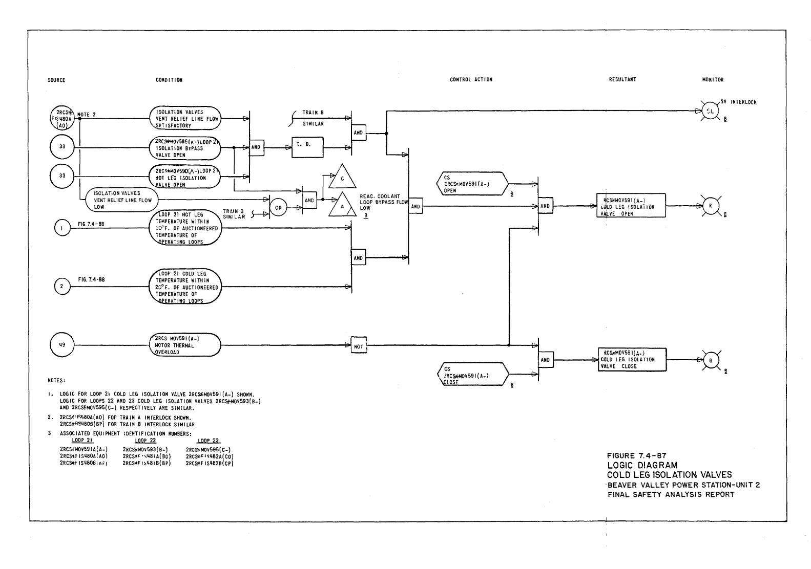
SOURCE
ISOLATION VALVES VENT RELIEF LINE FLOW LOW
FIG. 7.4-88
FIG. 7.4-88
NOTES:
CONDITION
I SOLA Tl OK VAL YES VENT RELIEF LINE FLOW SHISFACTORY
ZRC~OVSB~(A-)LOOP2 I SOLA Tl ON BTPASS VALVE OPEN
2RCS-ttMO V590(j\ -) ~00 P 2 HOT L[G ISOLATION
ALVE OPEN
OOP 21 HOT LEG TEMPERATURE WITHIN cO~F. OF AUCTIONEERED TEMPERATURE OF
ERATIIIG LOOPS
2RCS MOV591 (A-) MOTOR THERMAL OVERLOAD
TRAIN B SIMILAR
I. LOGIC FOR LOOP 21 COLD LEG ISOLATION VALVE 2RCS*MOV591 (A-} SHOWN. LOGIC FOR LOOPS 22 AND 23 COLD LEG ISOLATION VALVES 2RCstMOV593(B-} AND 2RCSfMOV595(C-) RESPECTIVELY ARE SIMILAR.
2. 2R CS-'f'19180A ( AO) FOP TRA IN A IN fER LOCK SHOWN. 2RCS~ISI+80S ( BP) FOR TRA IN B INTERLOCK S IM ILA R
3 ASSOCIATED EQUIPMENT IOE~TIFICATION NUMBERS: LOOP 21 LOOP 22 LOOP 23
2RCS~ MOV591 A (A-) 2 RCS)!MQV 593 (B-) 2RCS'+-MOV595 (C-) 2RCS1-F I sqSQA/ AQ} 2RCS.ll~ • .;qsl A( BC) 2RCS*~ I ~ij82A( CO) 2RCS.fiSq8061ArJ 2RCS*Ft~q81B(BP) 2RC~FISqB2B(CP)
TRAIN B
SIMILAR
REAC. COOLANT LOOP BYPASS FLO LOW
B
CONTROL ACTION
cs Z.RC S>I:MOV591 (A-) OPEN
cs ZRCSJOO)V591 ( A-1 CLOSE
RESULTANT
CS¥-M0¥591 {A-) C~LD LEG ISOLATION V/riLYE OPEN
!lCs,Ho!OV591(A-) !----~CilLO LEG ISOLATION
VALVE CLOSE
FIGURE 7.4-87 LOGIC DIAGRAM
MONITOR
sv I NTERLOCI!.
l
~
COLD LEG ISOLATION VALVES ·BEAVER VALLEY POWER STATION-UNIT 2 FINAL SAFETY ANALYSIS REPORT
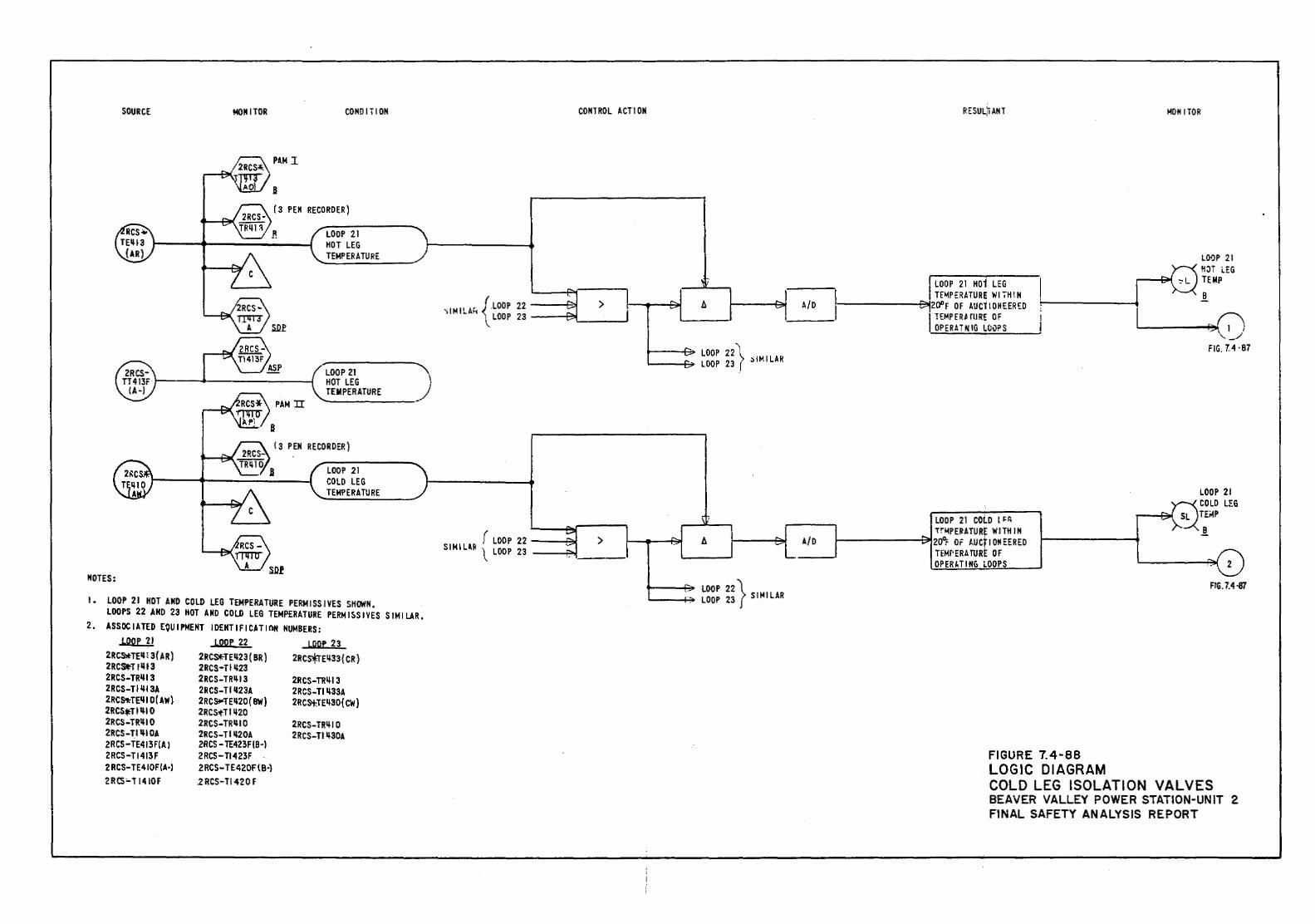
SOURCE MONITOR CONO ITI ON
PAM I
B
{3 PEN RECORDER)
LOOP 21 HOT LEG TEMPERATURE
LOOP 21 HOT LEG TEMPERATURE
( 3 PEN RECORDER)
LOOP 21 COLD LEG TEMPERATURE
NOTES:
I. lOOP 21 HOT AND COLD LEG TEMPERATURE PERMISSJVES SHOWN. LOOPS 22 AND 23 HOT AND COLD LEG TEMPERATURE PERMISSIVES SIMILAR.
2. ASSOCIATED EQUIPMENT IDENTIFICATION NUMBERS: LOOP 21 LOOP 22 LDD:e 23
2RCS*TEIJ! 3( A R) 2RCS*-TEII23 ( BR) 2RCsfrEIJ33(CR) 2RCSII."TIII13 2RCS•TIII23 2RCS-TR1113 2RCS-TRIJI3 2RCS-TRII13 2RCS-Till I 3A 2RCS-TIIJ23A 2RCS-TIII33A 2RC&f<TEIJ I 0 ( AW) 2RCSI":TEII2D(BW) 2RCSi:TEIJ30{ CW) 2RCStTIIII 0 2RCSi:TIIJ20 2RCS-TRIJIO 2RCS-TRIJIO 2RCS-TRIIIO 2RCS-TIIJIOA 2RCS-T IIJ20A 2RCS-TIIJ30A 2RCS-TE413F(A) 2RCS- TE423F 18-l 2RCS-TI413F 2RCS- TI423F 2RCS-TE410F(A-l 2RCS-TE420F{B-l 2RCS'-T 1410F 2RCS-TI420F
CONTROL ACTl ON
{_LOOP 22
'iiMILAf-1 LOOP 23 -----t:!JL __ _J > A/0
LOOP 22l IM ILAR 1-----b> LOOP 23 ( ;)
r LOOP 22 ---Bo! SIMILlR ~LOOP 23 ---f."'!t ____ l
> A/0
LOOP 22} 1--..--+-~. LOOP 23 S I lot IL AR
RESUL~ ANT
LOOP 21 COlD I ~r, Tr~PE~ATUR! WITHIN
1------~20~ OF AUC I~EERED TEMPERATUR OF OP ER I.T I HG LOOPS
FIGURE 7.4-88 LOGIC DIAGRAM
MONITOR
LOOP 21 HOT i.EG TEMP
B
1 _/
FIG. 7.4 · 87
LOOP 21 COLD LEG TE;.tP
.!
FIG. 7.4-87
COLD LEG ISOLATION VALVES BEAVER VALLEY POWER STATION-UNIT 2 FINAL SAFETY ANALYSIS REPORT
BVPS-2 UFSAR Rev. 0
7.5-1
7.5 SAFETY-RELATED DISPLAY INSTRUMENTATION 7.5.1 Introduction An analysis was conducted to identify the appropriate variables and to establish the appropriate design bases and qualification criterion for instrumentation employed by the operator for monitoring conditions in the reactor coolant system (RCS), the secondary heat removal system, and the reactor containment, including engineered safety functions and the systems employed for attaining a safe shutdown condition. The instrumentation is used by the operator to monitor Beaver Valley Power Station - Unit 2 (BVPS-2) throughout all operating conditions, including anticipated operational occurrences, accident, and post-accident conditions in accordance with the position stated in Section 1.8 for Regulatory Guide 1.97. 7.5.2 Description of Information Systems The BVPS-2 safety analyses and evaluations referenced in Chapter 15 and the Westinghouse Owners Group Emergency Response Guidelines define the design basis accident (DBA) event scenarios for which preplanned operator actions are required. Accident monitoring instrumentation is necessary to guide the operator in taking required actions to address these analyzed situations. However, instrumentation is also necessary for unforeseen situations (that is, to ensure that should BVPS-2 conditions evolve differently than predicted by the safety analyses, the main control room operating staff has sufficient information to evaluate and monitor the course of the event). Additional instrumentation is also needed to indicate to the operating staff whether the integrity of the in-core fuel clad, the RCS pressure boundary, or the reactor containment has degraded beyond the prescribed limits defined as a result of the BVPS-2 safety analyses and other evaluations. The following five classifications of variables have been identified to provide this instrumentation:
1. Operator manual actions, identified in the operating procedures that are associated with DBA events, are preplanned. Those variables that provide information needed by the operator to perform these manual actions are designated Type A. The basis for selecting Type A variables is given in Section 7.5.2.2.1.
2. Those variables needed to assess that BVPS-2 critical safety
functions are being accomplished or maintained, as identified in the BVPS-2 safety analyses and other evaluations, are designated Type B.
BVPS-2 UFSAR Rev. 0
7.5-2
3. Variables used to monitor for the gross breach, or the potential for gross breach, of the in-core fuel clad, the RCS pressure boundary, or the reactor containment, are designated Type C. Variables used to monitor the potential breach of containment have an arbitrarily determined extended range. The extended range is chosen to minimize the probability of instrument saturation even if conditions exceed those predicted by the safety analyses. The response characteristics of Type C information display channels will allow the main control room staff to detect conditions indicative of gross failure of any of the three fission product barriers, or the potential for gross failure of these barriers. Although variables selected to fulfill Type C functions may rapidly approach the values that indicate an actual gross failure, it is the final steady-state value reached that is important. Therefore, a high degree of accuracy is not necessary for Type C information display channels.
4. Those variables needed to assess the operation of individual
safety systems, and other systems important to safety, are designated Type D.
5. The variables that are required for use in determining the
magnitude of the postulated releases, and continually assessing any such releases of radioactive materials, are designated Type E.
The five classifications of variables are not mutually exclusive, in that a given variable (or instrument) may be included in one or more types. When a variable is included in one or more of the five classifications, the equipment monitoring this variable is specified in accordance with the highest category identified. Three categories of design and qualification criteria have been identified. The differentiation is made in order that a hierarchy of information is recognized in specifying accident monitoring instrumentation. Category 1 instrumentation has the highest performance requirements and should be utilized for information which cannot be lost under any circumstances. Category 2 and Category 3 instruments are of lesser importance in determining the state of BVPS-2 and do not require the same level of operational assurance. The primary differences between category requirements are in qualification, single failure, power supply, and display requirements. Category 1 requires seismic and environmental qualification, the application of the single failure criterion, utilization of emergency power sources, and an immediately accessible display. Category 2 requires seismic and environmental qualification commensurate with the required function but does not require the single failure criterion, emergency power sources, or an immediately accessible display. Category 2 does require a rigorous performance

BVPS-2 UFSAR Rev. 0
7.5-2a
verification for a single instrument channel. Category 3, which is high quality commercial grade equipment, does not require seismic
BVPS-2 UFSAR Rev. 16
7.5-3
or environmental qualification, single failure criterion, emergency power, or an immediately accessible display. Table 7.5-1 summarizes the following information for each variable identified:
1. Instrument range/status, 2. Environmental qualification, 3. Seismic qualification, 4. Display methodology (number of channels and indicator
device), and 5. Type/category.
7.5.2.1 Definitions 7.5.2.1.1 Design Basis Accident Events Those events, any one of which could occur during the lifetime of a particular plant, and those events not expected to occur but postulated because their consequences would include the potential for release of significant amounts of radioactive gaseous, liquid, or particulate material to the environment, are DBA events. Excluded are those events (defined as normal and anticipated operational occurrences in 10 CFR 50) expected to occur more frequently than once during the lifetime of a particular plant. The limiting accidents that were used to determine instrument functions are:
1. Loss-of-coolant accident (LOCA), 2. Main steam line break (MSLB), 3. Feedwater line break, and 4. Steam generator tube rupture.
7.5.2.1.2 Safe Shutdown (Hot Standby) The state of BVPS-2 in which the reactor is subcritical such that Keff is less than or equal to 0.99 and the RCS temperature is greater than or equal to 350°F. Additional features are provided to reach and maintain a cold shutdown plant condition. These are discussed in Section 5.4.7. 7.5.2.1.3 Controlled Condition The state of the plant that is achieved when the subsequent action portion of the BVPS-2 emergency operating procedures (EOP) is
BVPS-2 UFSAR Rev. 0
7.5-4
implemented and the critical safety functions are being accomplished or maintained by the main control room operating staff. 7.5.2.1.4 Critical Safety Functions Those safety functions that are essential to prevent a direct and immediate threat to the health and safety of the public. These are the accomplishing or maintaining of:
1. Reactivity control, 2. Reactor coolant system pressure control, 3. Reactor coolant inventory control, 4. Reactor core cooling, 5. Heat sink maintenance, and 6. Reactor containment environment.
7.5.2.1.5 Immediately Accessible Information Information that is visually available to the main control room operating staff immediately (that is, within human response time requirements) once they have made the decision that the information is needed. 7.5.2.1.6 Primary Information Information that is essential for the direct accomplishment of the preplanned manual actions necessary to bring BVPS-2 into a safe condition in the event of a DBA event. It does not include those variables that are associated with contingency actions. 7.5.2.1.7 Contingency Actions Those manual actions that address conditions beyond the DBA event. 7.5.2.1.8 Key Variables Those variables which provide the most direct measure of the information required. 7.5.2.1.9 Backup Information That information, made up of additional variables beyond those classified as key, that provide supplemental and/or confirmatory information to the main control room operating staff. Backup variables do not provide indications as reliable or complete as those provided by primary variables, and are not usually relied upon as the sole source of information.
BVPS-2 UFSAR Rev. 0
7.5-5
7.5.2.1.10 Categories 1, 2, and 3 References to Categories 1, 2, and 3 are as stated in Regulatory Guide 1.97 Category Classifications. 7.5.2.2 Variable Types The accident monitoring variables and information display channels are those required to enable the main control room operating staff to perform the functions defined by Type A, B, C, D, and E classifications as follows. 7.5.2.2.1 Type A Those variables that provide the primary information required to permit the main control room operating staff to:
1. Perform the diagnosis specified in the BVPS-2 EOPs, 2. Take the specified preplanned manually controlled actions,
for which no automatic control is provided and that are required for safety-related systems to accomplish their safety function, in order to recover from the DBA event, and
3. Reach and maintain a safe shutdown (hot standby) condition.
The verification of the actuation of safety-related systems has been excluded from the Type A definition. The variables which provide this verification are included in the definition of Type D. Variables in Type A are restricted to preplanned actions for DBA events. Contingency actions and additional variables which might be utilized will be in Types B, C, D, and E. 7.5.2.2.2 Type B Those variables that provide the main control room operating staff with information to assess the process of accomplishing or maintaining critical safety functions, that is, reactivity control, RCS pressure control, RCS inventory control, reactor core cooling, heat sink maintenance, and reactor containment environment. 7.5.2.2.3 Type C Those variables that provide the main control room operating staff the information to monitor:
1. The extent to which variables that indicate the potential for causing a gross breach of a fission product barrier have exceeded the design basis values, and
BVPS-2 UFSAR Rev. 0
7.5-6
2. That the in-core fuel clad, the RCS pressure boundary, or the reactor containment may have been subjected to gross breach.
These variables include those required to initiate the early phases of the emergency plan. Excluded are those associated with monitoring radiological release from BVPS-2, which are included in Type E. Type C variables used to monitor the potential for breach of a fission product barrier have an arbitrarily determined extended range. The extended range was chosen to minimize the probability of instrument saturation even if conditions exceed those predicted by the safety analysis. 7.5.2.2.4 Type D Those variables that provide the main control room operating staff with sufficient information to monitor the performance of:
1. Plant safety systems employed for mitigating the consequences
of an accident and subsequent BVPS-2 recovery to attain a safe shutdown condition. These include verification of the automatic actuation of safety-related systems, and
2. Other systems normally employed for attaining a safe shutdown
(hot standby) condition. 7.5.2.2.5 Type E Those variables that provide the main control room operating staff with information to:
1 Monitor the habitability of the main control room, 2. Estimate the mamitude of release of radioactive material
through identified pathways and continually assess such releases, and
3. Monitor and estimate radiation levels and radioactivity in
the environment surrounding BVPS-2. 7.5.2.3 Variable Categories The qualification requirements of the Type A, B, C, D, and E accident monitoring instrumentation are subdivided into three categories. Descriptions of the three categories are given in the following. Table 7.5-2 briefly summarizes the selection criteria for Type A, B, C, D, and E variables in each of the three categories. Table 7.5-3 briefly summarizes the design, qualification, and interface requirements of these three designated categories.
BVPS-2 UFSAR Rev. 0
7.5-7
7.5.2.3.1 Category 1 7.5.2.3.1.1 Selection Criteria for Category 1 The selection criteria for Category 1 variables have been subdivided according to the variable type. For Type A, those key variables used for diagnosis or providing information for necessary operator action have been designated Category 1. For Type B, those key variables which are used for monitoring the process of accomplishing or maintaining critical safety functions have been designated Category 1. For Type C, those key variables which are used for monitoring the potential for breach of a fission product barrier have been designated Category 1. There are no Type D or Type E Category 1 variables. 7.5.2.3.1.2 Qualification Criteria for Category 1 The instrumentation is environmentally and seismically qualified in accordance with Sections 3.11 and 3.10, respectively. Instrumentation shall continue to read within the required accuracy following, but not necessarily during, a seismic event. At least one instrumentation channel is qualified from a sensor up to and including a display. For the balance of the instrumentation channels, qualification applies up to and includes the channel isolation device (Refer to Section 7.5.2.3.4 with regard to extended range instrumentation qualification). 7.5.2.3.1.3 Design Criteria for Category 1
1. No single failure within either the accident monitoring
instrumentation, its auxiliary supporting features, or its power sources, concurrent with the failures that are a condition of or result from a specific accident, will prevent the main control room operating staff from being presented the required information. Where failure of one accident monitoring channel results in information ambiguity (for example, the redundant displays disagree), additional information is provided to allow the control room operating staff to analyze the actual conditions in the plant. This may be accomplished by providing additional independent channels of information of the same variable (addition of an identical channel), or by providing independent channels which monitor different variables that bear known relationships to the multiple channels (addition of a diverse channel(s)). Redundant or diverse channels are electrically independent and physically separated from each other, to the extent practicable with two train separation, and from equipment not classified important to safety in accordance with the position stated in Section 1.8 for Regulatory Guide 1.75.
BVPS-2 UFSAR Rev. 0
7.5-8
For situations such as isolation valves in series, the intent is generally to verify the isolation function. In such a situation a single indication on each valve is sufficient to satisfy the single failure criterion if those indications are from different trains (that is, unambiguous indication of isolation). If ambiguity does not result from failure of the channel, then a third redundant or diverse channel is not required.
2. The instrumentation is energized from station emergency power
sources and battery-backed where momentary interruption is not tolerable, as discussed in Regulatory Guide 1.32.
3. The out-of-service interval is based on normal Technical
Specification requirements for the system it serves where applicable, or where specified by other requirements.
4. Servicing, testing, and calibration programs are specified to
maintain the capability of the monitoring instrumentation. Those instruments, for which the required interval between testing is less than the normal time interval between BVPS-2 shutdowns, are provided with a capability for testing during power operation.
5. Whenever means for removing channels from service are
included in the design, the design provides administrative control of the access to such removal means.
6. The design provides administrative control of the access to
all set point adjustments, module calibration adjustments, and test points.
7. The monitoring instrumentation design minimizes the
development of conditions that would cause meters, annunciators, recorders, alarms, etc., to give anomalous indications that could be potentially confusing to the main control room operating staff.
8. The instrumentation is designed to facilitate the
recognition, location, replacement, repair, or adjustment of malfunctioning components or modules.
9. To the extent practicable, monitoring instrumentation inputs
are from sensors that directly measure the desired variables. An indirect measurement is made only when it can be shown by analysis to provide unambiguous information.
10. Periodic checking, testing, calibration, and calibration
verification is done in accordance with the applicable portions of Regulatory Guide 1.118.

BVPS-2 UFSAR Rev. 0
7.5-8a
11. The range selected for the instrumentation encompasses the expected operating range of the variable being monitored, to
BVPS-2 UFSAR Rev. 0
7.5-9
the extent that saturation does not negate the required action of the instrument, in accordance with the applicable portions of Regulatory Guide 1.105.
7.5.2.3.1.4 Information Processing and Display Interface Criteria for
Category 1 The interface criteria specified here provide requirements to be implemented in the processing and displaying of the information.
1. The main control room operating staff have immediate access to the information from redundant or diverse channels in units of measure familiar to them (that is, for temperature reading, degrees are used, not volts). Where two or more instruments are needed to cover a particular range, overlapping instrument spans are provided.
2. A historical record of at least one instrumentation channel
for each process variable is maintained. A recorded pre-event history for these channels is required for a minimum of 1 hour, and continuous recording of these channels is required following an accident until such time as continuous recording of such information is no longer deemed necessary. This recording is to be available when required and does not need to be immediately accessible.
The time period of 1 hour was selected based on a
representatively slow transient which is bounded by this time requirement. A 1/2 inch equivalent break area LOCA was selected since the trip occurs at approximately 50 minutes after initiation. Where direct and immediate trend or transient information is essential for operator information or action, the recording is immediately accessible.
7.5.2.3.2 Category 2 7.5.2.3.2.1 Selection Criteria for Category 2 The selection criteria for Category 2 variables are subdivided according to the variable type. For Types A, B, and C, those variables which provide preferred backup information are designated Category 2. For Type D, those key variables used for monitoring the performance of safety systems have been designated Category 2. For Type E, those key parameters to be monitored for use in determining the magnitude of the release of radioactive materials and for continuously assessing such releases have been designated Category 2. 7.5.2.3.2.2 Qualification Criteria for Category 2 Category 2 instrumentation is qualified from the sensor up to and including the isolation device for at least the environment in which it must operate to perform its intended function. Instrumentation
BVPS-2 UFSAR Rev. 0
7.5-10
associated with those safety-related systems that are required to operate following a safe shutdown earthquake (SSE), to mitigate a consequential plant incident, shall be seismically qualified. Environmental qualification will meet, or exceed the requirements of IEEE Standard 323-1971, 1974, and NUREG-0588, Revision 1 (USNRC 1981), which interprets BVPS-2 as being a Category II type plant. Seismic qualification is conducted in accordance with IEEE Standard 344-1971, 1975, if this instrumentation is part of a safety-related system. 7.5.2.3.2.3 Design Criteria for Category 2
1. The instrumentation is energized from a highly reliable on-site power source, not necessarily the emergency power source, which is battery-backed where momentary interruption is not tolerable.
2. The out-of-service interval is based on normal Technical
Specification requirements for the system it serves where applicable, or where specified by other requirements.
3. Servicing, testing, and calibration programs are specified to
maintain the capability of the monitoring instrumentation. For those instruments where the required interval between testing is less than the normal time interval between BVPS-2 shutdowns, a capability for testing during power operation is provided.
4. Whenever means for removing channels from service are
included in the design, the design facilitates administrative control of the access to such removal means.
5. The design facilitates administrative control of the access
to all setpoint adjustments, module calibration adjustments, and test points.
6. The monitoring instrumentation design minimizes the potential
for the development of conditions that would cause meters, annunciators, recorders, and alarms, etc., to give anomalous indications that could be potentially confusing to the operator.
7. The instrumentation is designed to facilitate the
recognition, location, replacement, repair, or adjustment of malfunctioning components or modules.
8. To the extent practicable, monitoring instrumentation inputs
are from sensors that directly measure the desired variables. An indirect measurement is made only when it can be shown by analysis to provide unambiguous information.
BVPS-2 UFSAR Rev. 15
7.5-11
9. Periodic checking, testing, calibration, and calibration verification is in accordance with applicable portions of Regulatory Guide 1.118.
10. The range selected for the instrumentation encompasses the
expected operating range of the variable being monitored, to the extent that saturation does not negate the required action of the instrument, in accordance with the applicable portions of Regulatory Guide 1.105.
7.5.2.3.2.4 Information Processing and Display Interface Criteria for Category 2.
The instrumentation signal is, as a minimum, processed for display on demand. Recording requirements are determined on a case-by-case basis.
7.5.2.3.3 Category 3 7.5.2.3.3.1 Selection Criteria for Category 3 The selection criteria for Category 3 variables have been subdivided according to the variable type. For Types A, B, and C, variables which can provide backup information are usually designated Category 3, unless they are primary backup variables, in which case they would be classified as Category 2. For Types D and E, those variables which provide preferred backup information have been designated Category 3.
7.5.2.3.3.2 Qualification Criteria for Category 3 The instrumentation is high quality commercial grade that is not required to provide information when exposed to a post-accident adverse environment. Only normal and abnormal environments are applicable.
7.5.2.3.3.3 Design Criteria for Category 3
1. Servicing, testing, and calibration programs are specified to
maintain the capability of the monitoring instrumentation. For those instruments where the required interval between testing is less than the normal interval between BVPS-2 shutdowns, a capability for testing during power operation is provided.
2. Whenever means for removing channels from service are
included in the design, the design facilitates administrative control of the access to such removal means.
3. The design facilitates administrative control of the access
to all set point adjustments, module calibration adjustments, and test points.
BVPS-2 UFSAR Rev. 0
7.5-12
4. The monitoring instrumentation design minimizes the potential for the development of conditions that would cause meters, annunciators, recorders, and alarms, etc, to give anomalous indications that could be potentially confusing to the operator.
5. The instrumentation is designed to facilitate the
recognition, location, replacement, repair, or adjustment of malfunctioning components or modules.
6. To the extent practicable, monitoring instrumentation
inputs are from sensors that directly measure the desired variables. An indirect measurement is made only when it can be shown by analysis to provide unambiguous information.
7.5.2.3.3.4 Information Processing and Display Interface Criteria for
Category 3 The instrumentation signal is, as a minimum, processed for display on demand. Recording requirements are determined on a case-by-case basis. 7.5.2.3.4 Extended Range Instrumentation Qualification Criteria The qualification environment for extended range instrumentation is based on the DBA events, except the assumed maximum value of the monitored variable shall be the value equal to the specified maximum range for the variable. The monitored variable is assumed to approach this peak by extrapolating the most severe initial ramp associated with the DBA events. The decay for this variable is considered proportional to the decay for the variable associated with the DBA events. No additional qualification margin needs to be added to the extended range variable. All environmental envelopes, except that pertaining to the variable measured by the information display channel, are those associated with the DBA events. The environmental qualification requirement for extended range equipment does not account for steady-state elevated levels that may occur in other environmental parameters associated with the extended range variable. For example, a sensor measuring containment pressure must be qualified for the measured process variable range (that is, three times design pressure for concrete containments), but the corresponding ambient temperature is not mechanistically linked to that pressure. Rather, the ambient temperature value is the bounding value for DBA events analyzed in Chapter 15. The extended range requirement is to ensure that the equipment will continue to provide information if conditions degrade beyond those postulated in the safety analysis. Since extended variable ranges are non-mechanistically determined, extension of associated parameter levels is not justifiable and is therefore not required.
BVPS-2 UFSAR Rev. 0
7.5-13
7.5.3 Description of Variables 7.5.3.1 Type A Variables Type A variables are defined in Section 7.5.2.2.1. They are the variables which provide primary information required to permit the main control room operating staff to:
1. Perform the diagnosis specified in the BVPS-2 EOPs, 2. Take specified preplanned manually controlled actions for
which no automatic control is provided and that are required for safety systems to accomplish their safety function to recover from a DBA event (verification of actuation of safety systems is excluded from Type A and is included as Type D), and
3. Reach and maintain a safe shutdown (hot standby) condition.
Key Type A variables have been designated Category 1. These are the variables which provide the most direct measure of the information required. The key Type A variables are:
1. Reactor coolant system pressure (wide range), 2. Reactor coolant hot leg temperature (Thot) (wide range), 3. Reactor coolant cold leg temperature (Tcold) (wide range), 4 Steam generator level (wide range), 5. Steam generator level (narrow range), 6. Pressurizer level, 7. Reactor containment pressure, 8. Steamline pressure, 9. Reactor containment water level (wide range), 10. Reactor containment water level (narrow range), 11. Primary plant demineralized water storage tank level, 12. Auxiliary feedwater flow, 13. Reactor containment area radiation level, 14. Core exit temperature, and 15. Secondary system radiation - main steamline radiation.
BVPS-2 UFSAR Rev. 0
7.5-14
Preferred backup Type A variables have been designated Category 2. RCS subcooling is designated as Type A, Category 2. The BVPS-2 recognizes that the degree of subcooling can be obtained from system pressure and temperature using Type A, Category 1 variables and a steam table. However, it is also recognized that the main control room staff will also have access to their subcooling monitor (required by the U.S. Nuclear Regulatory Commission (USNRC) NUREG-0737, Action Item 11.F.2). Therefore, RCS subcooling is considered a backup Type A variable which, in turn, requires Category 2 qualification. No Type A variable has been designated Category 3. A summary of the Type A variables is provided in table 7.5-4. 7.5.3.2 Type B Variables Type B variables are defined in Section 7.5.2.2.2. They are the variables that provide information to the main control room operating staff to assess the process of accomplishing or maintaining critical safety functions, that is:
1. Reactivity control, 2. Reactor coolant system pressure control, 3. Reactor coolant inventory control, 4. Reactor core cooling, 5. Heat sink maintenance, and 6. Reactor containment environment.
Variables which provide the most direct indication (that is, key variables) to assess each of the six critical safety functions have been designated Category 1. Preferred backup variables have been designated Category 2. All other backup variables are Category 3. The Type B variables are listed in Table 7.5-5. 7.5.3.3 Type C Variables Type C variables are defined in Section 7.5.2.2.3. Basically, they are the variables that provide the main control room operating staff with information to monitor the potential for breach or actual gross breach of:
1. In-core fuel clad,
BVPS-2 UFSAR Rev. 0
7.5-15
2. Reactor coolant system boundary, and 3. Containment boundary.
(Variables associated with monitoring of radiological release from BVPS-2 are included in Type E).
Those Type C key variables which provide the most direct measure of the potential for breach of one of the three fission product boundaries have been designated Category 1. Backup information indicating potential for breach is designated Category 2. Variables which indicate actual breach have been designated as preferred backup information and are qualified to Category 2. Table 7.5-6 summarizes the selection of Type C variables. 7.5.3.4 Type D Variables Type D variables are defined in Section 7.5.2.2.4. They are those variables that provide sufficient information to the main control room operating staff to monitor the performance of:
1. Plant safety systems employed for mitigating the consequences of an accident and subsequent BVPS-2 recovery to attain a safe shutdown condition, including verification of the automatic actuation of safety systems, and
2. Other systems normally employed for attaining a safe shutdown
condition. Type D key variables are designated Category 2. Preferred backup information is designated Type D, Category 3. The following systems or major components have been identified as requiring Type D information to be monitored:
1. Pressurizer level and pressure control (assess status of RCS following return to normal pressure and level control under certain post-accident conditions),
2. Chemical and volume control system (employed for attaining
safe shutdown under certain post-accident conditions), 3. Secondary pressure and level control (employed for
restoring/maintaining a secondary heat sink under post-accident conditions),
4. Emergency core cooling system, 5. Auxiliary feedwater system, 6. Containment systems,
BVPS-2 UFSAR Rev. 0
7.5-16
7. Component cooling water system, 8. Service water system, 9. Residual heat removal system, 10. Heating, ventilation, and air-conditioning systems (if
required for engineered safety features operation), 11. Electric power to vital safety systems, and 12. Verification of automatic actuation of safety systems.
Table 7.5-7 lists the key Type D variables identified for each system listed above. For the purpose of specifying seimsic qualification for Type D, Category 2 variables, it is assumed that a seismic event and a break in Category 1 piping will not occur concurrently. As a result, the limiting event is unisolated (single failure of a main steamline isolation valve) break in Class 2 main steam piping. Instrumentation associated with the safety systems which are required to mitigate, and the instrumentation necessary to monitor, this event should be seismically qualified. Similarly, the environmental qualification of Type D, Category 2 variables depends on whether the instrumentation is subject to a high energy line break (HELB) when required to provide information. 7.5.3.5 Type E Variables Type E variables are defined in Section 7.5.2.2.5. They are those variables that provide the main control room operating staff with information to:
1. Monitor the habitability of the main control room, 2. Estimate the magnitude of release of radioactive materials
through identified pathways, and 3. Monitor and estimate radiation levels and radioactivity in
the environment surrounding BVPS-2. Key Type E variables are qualified to Category 2 requirements. Preferred backup Type E variables are qualified to Category 3 requirements. Table 7.5-8 lists the key Type E variables. 7.5.4 Additional Information A cross-reference of the variable and category for each instrument identified in the BVPS-2 survey is included in Table 7.5-9.
BVPS-2 UFSAR Rev. 13
7.5-17
Table 7.5-1 identifies the instruments utilized at BVPS-2 which address the recommendations of both NUREG-0737 (USNRC 1980) and Regulatory Guide 1.97. The instruments identified meet the intent of the guidance provided in NUREG-0737. 7.5.5 Bypass and Inoperable Status Indication This plant computer-based system is utilized in conjunction with the main annunciator system to provide indication of the bypass or inoperability of each redundant portion of a system that performs a safety-related function. Bypass indication may be applied administratively or automatically. The systems which are covered by Table 7.5-10 are designed in accordance with the guidelines of Regulatory Guide 1.47. Specific inputs are shown on Figures 7.5-1, 7.5-2, 7.5-3, 7.5-4, 7.5-5, 7.5-6, 7.5-7, 7.5-8, 7.5-9, 7.5-10, 7.5-11, 7.5-12, 7.5-13, 7.5-14, 7.5-15, 7.5-16, 7.5-17, 7.5-18, 7.5-19, 7.5-20, 7.5-21, 7.5-22, 7.5-23, 7.5-24, 7.5-25, 7.5-26, 7.5-27, 7.5-28, 7.5-29, 7.5-30, 7.5-31, 7.5-32, 7.5-33 and 7.5-34. Compliance with Regulatory Guide 1.47 for bypassed and inoperable status design philosophy is described below:
1. A bypass indicator is provided for each protection system. "Bypass" includes any deliberate action which renders a protection system inoperable.
2. The indicator is at the system level with a separate
indicator for each train. 3. The indicator is operated automatically only by actions which
meet all these criteria: a. The action is deliberate. (Component failure may be
indicated by component failure indicators but should not operate the system bypass indicator. It is not the intent of the indicator to show operator errors or component failures.)
b. The action is expected to occur more often than once a
year. This "more often than once a year" criterion is interpreted liberally. If an accessible, permanently installed electrical control device will bypass a safety system, it is assumed that the device will be used more than once a year. Also, manual valves or nonremotely controlled devices within the containment are not accessible.
c. The action is expected when the protection system must
be operable. (Bypass of source range flux trip during normal power operation would not, for example, be indicated on the system bypass indicator. It may be indicated on a channel or component status indicator.)
d. The action renders the system inoperable, not merely
potentially inoperable. (If, for example, redundant, parallel, 100-percent valves are provided for the discharge line of a spray pump, the system bypass indicator would not
BVPS-2 UFSAR Rev. 0
7.5-18
be actuated by the closing of only one of those valves. Valve closing may be indicated on a component status indicator.
e. Some deliberate action has taken place in the protection
system or a necessary supporting system. (For example, if the cooling water inlet valve for a recirculation spray heat exchanger is deliberately closed, the system bypass indicator for the recirculation spray system would be operated.)
4. The bypass indicators are separate from other plant
indicators and grouped in a logical fashion. 5. A capability is provided to operate each bypass indicator
manually. This lets the operator provide bypass indication for an event that renders a safety system inoperable but does not automatically operate the system bypass indicator.
6. There is not any capability to defeat an automatic operation
of a bypass indicator. (Audible alarms may be silenced.) 7. The bypass indicators are accompanied by audible alarm. 8. The indication system is mechanically and electrically
isolated from the safety system to avoid degradation of the safety system. No fault in the indicator system can impair the ability of the safety system to perform its safety-related function. The bypass indicators are not considered safety-related; i.e., they need not be designed to safety system criteria such as IEEE Standard 279-1971.
9. In accordance with IEEE Standard 279-1971, Paragraph 4.20,
the operator must be able to determine why a system level bypass is indicated. This information is provided by the plant computer.
10. Service water system inoperative and diesel generator
inoperative indicators are provided. These support systems are unique and important enough to warrant bypass indicators.
11. The system design meets the recommendations of ICSB-21 as
follows:
a. Each safety system has a Train A (orange) and Train B (purple) bypass indicator. The indicators are grouped together by train on the main control board. Support systems have white bypass indicators and are arranged together with the associated train of bypass indicators. Safety system indicators are lit whenever any support subsystem is inoperable as described in No. 3 above.
b. Means by which the operator can cancel erroneous
bypassed indicators are not provided.
BVPS-2 UFSAR Rev. 16
7.5-19
c. The bypass indication system does not perform functions essential to safety. No operator action is required based solely on the bypass indication.
d. The indication system has no effect on plant safety
systems. e. The bypass indicating and annunciating function can be
tested during normal plant operation. 7.5.6 Safety Parameter Display System The BVPS-2 design incorporates a Safety Parameter Display System (SPDS), as required by NUREG-0737, Action Item I.D.2 (USNRC 1980). Liquid Crystal Diode (LCD) displays are installed in the Main Control Room, the Technical Support Center, and in the Emergency Response Facility. The Safety Parameter Display System is included in the BVPS-2 plant computer system. The BVPS-2 plant computer system is configured with redundant central processor units for increased reliability and availability. The SPDS is designed to display the status of the following six critical safety functions (CSFs) to the operators.
1. Sub-criticality Status - for loss-of-subcriticality, loss-of-core shutdown
2. Core Cooling Status - for inadequate core cooling, degraded
core cooling, saturated core cooling
3. Heat Sink Status - for loss-of-secondary heat sink, steam generator overpressure, steam generator high level, loss-of-normal steam release capabilities
4. Vessel Integrity Status - for imminent pressurized thermal
shock, anticipated pressurized thermal shock
5. Containment Integrity Status - for high containment pressure, containment flooding, high containment radiation level
6. Inventory Status - for high pressurizer level, low
pressurizer level, voids in reactor vessel. Dynamic color-coded status blocks representing the six CSFs are located on every user display. Design of the displays incorporates accepted human factors engineering principles so the displayed information can be readily perceived and comprehended by the SPDS users. The system is designed to ensure that sufficient isolation exists to preclude propagation of system faults and subsequent degradation to safety systems from which the SPDS input signals originate. For a more complete discussion of isolation methods, refer to FSAR Section 8.3.
BVPS-2 UFSAR Rev. 0
7.5-20
The design of the SPDS has been subjected to a verification and validation (V&V) program to confirm that the design is sufficient to provide reasonable assurance that a continuous display of valid and reliable information is available from which the plant safety status can be addressed. 7.5.7 References for Section 7.5 U.S. Nuclear Regulatory Commission (USNRC) 1980. Clarification of TMI Action Plan Requirements. NUREG-0737. USNRC 1981. Interim Staff Position on Environmental Qualification of Safety-Related Electrical Equipment; Resolution of Generic Technical Activity A-24. NUREG-0588, Revision 1.

BVPS-2 UFSAR
Tables for Section 7.5
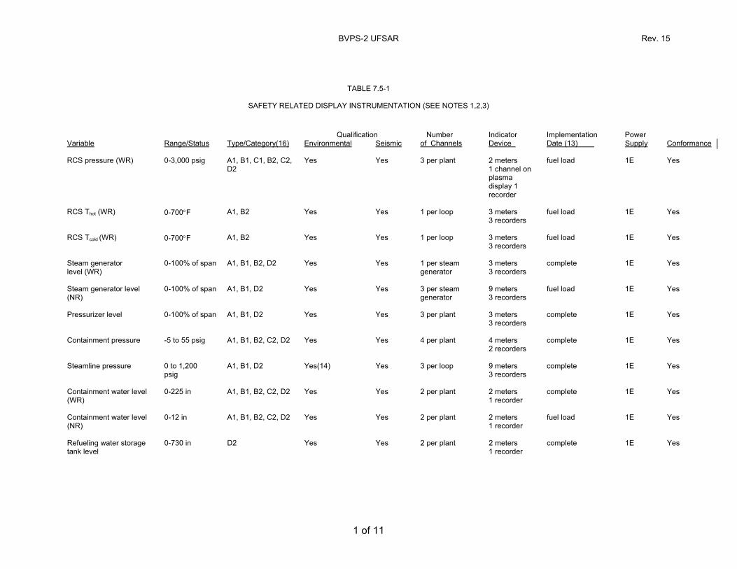
BVPS-2 UFSAR Rev. 15
1 of 11
TABLE 7.5-1
SAFETY RELATED DISPLAY INSTRUMENTATION (SEE NOTES 1,2,3) Qualification Number Indicator Implementation Power Variable Range/Status Type/Category(16) Environmental Seismic of Channels Device Date (13) Supply Conformance RCS pressure (WR) 0-3,000 psig A1, B1, C1, B2, C2,
D2 Yes Yes 3 per plant 2 meters
1 channel on plasma display 1 recorder
fuel load 1E Yes
RCS Thot (WR) 0-700°F A1, B2 Yes Yes 1 per loop 3 meters
3 recorders fuel load 1E Yes
RCS Tcold (WR) 0-700°F A1, B2 Yes Yes 1 per loop 3 meters
3 recorders fuel load 1E Yes
Steam generator level (WR)
0-100% of span A1, B1, B2, D2 Yes Yes 1 per steam generator
3 meters 3 recorders
complete 1E Yes
Steam generator level (NR)
0-100% of span A1, B1, D2 Yes Yes 3 per steam generator
9 meters 3 recorders
fuel load 1E Yes
Pressurizer level 0-100% of span A1, B1, D2 Yes Yes 3 per plant 3 meters
3 recorders complete 1E Yes
Containment pressure -5 to 55 psig A1, B1, B2, C2, D2 Yes Yes 4 per plant 4 meters
2 recorders complete 1E Yes
Steamline pressure 0 to 1,200
psig A1, B1, D2 Yes(14) Yes 3 per loop 9 meters
3 recorders complete 1E Yes
Containment water level (WR)
0-225 in A1, B1, B2, C2, D2 Yes Yes 2 per plant 2 meters 1 recorder
complete 1E Yes
Containment water level (NR)
0-12 in A1, B1, B2, C2, D2 Yes Yes 2 per plant 2 meters 1 recorder
fuel load 1E Yes
Refueling water storage tank level
0-730 in D2 Yes Yes 2 per plant 2 meters 1 recorder
complete
1E Yes
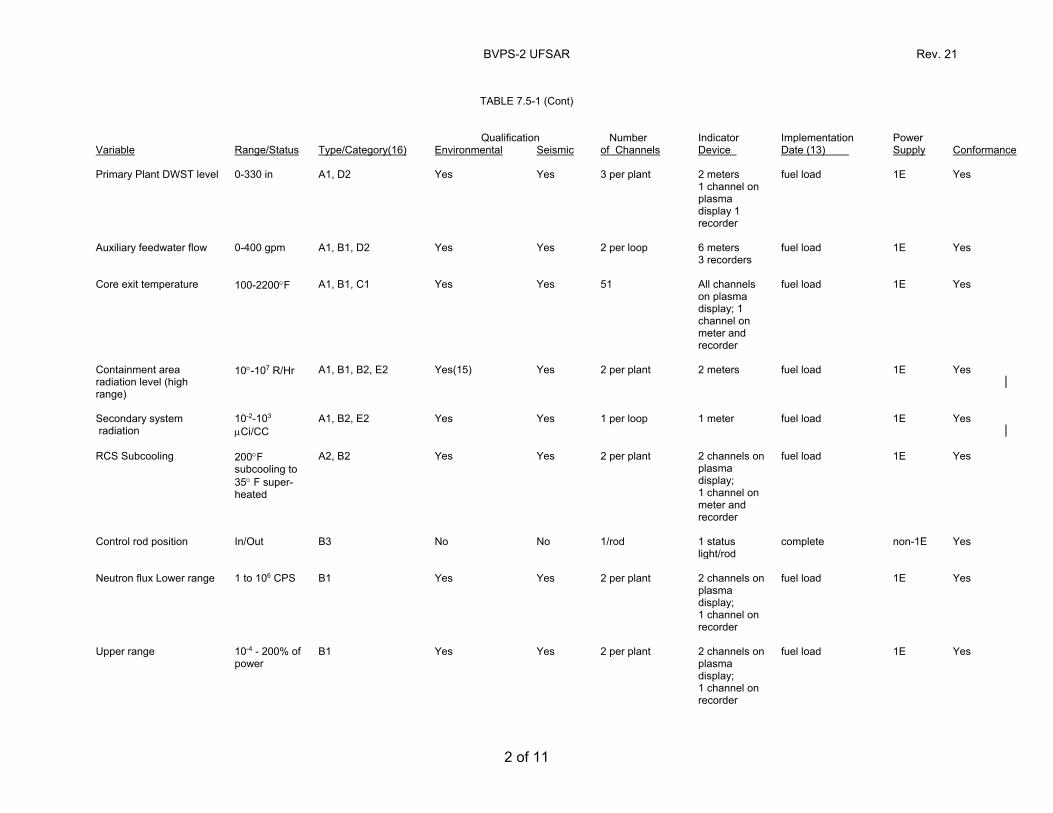
BVPS-2 UFSAR Rev. 21
2 of 11
TABLE 7.5-1 (Cont)
Qualification Number Indicator Implementation Power Variable Range/Status Type/Category(16) Environmental Seismic of Channels Device Date (13) Supply Conformance Primary Plant DWST level 0-330 in A1, D2 Yes Yes 3 per plant 2 meters
1 channel on plasma display 1 recorder
fuel load 1E Yes
Auxiliary feedwater flow 0-400 gpm A1, B1, D2 Yes Yes 2 per loop 6 meters
3 recorders fuel load 1E Yes
Core exit temperature 100-2200°F A1, B1, C1 Yes Yes 51 All channels
on plasma display; 1 channel on meter and recorder
fuel load 1E Yes
Containment area radiation level (high range)
10°-107 R/Hr A1, B1, B2, E2 Yes(15) Yes 2 per plant 2 meters
fuel load 1E Yes
Secondary system radiation
10-2-103 µCi/CC
A1, B2, E2 Yes Yes 1 per loop 1 meter
fuel load 1E Yes
RCS Subcooling 200°F
subcooling to 35° F super- heated
A2, B2 Yes Yes 2 per plant 2 channels on plasma display; 1 channel on meter and recorder
fuel load 1E Yes
Control rod position In/Out B3 No No 1/rod 1 status
light/rod complete non-1E Yes
Neutron flux Lower range 1 to 106 CPS B1 Yes Yes 2 per plant 2 channels on
plasma display; 1 channel on recorder
fuel load 1E Yes
Upper range 10-4 - 200% of
power B1 Yes Yes 2 per plant 2 channels on
plasma display; 1 channel on recorder
fuel load 1E Yes
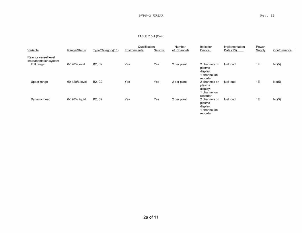
BVPS-2 UFSAR Rev. 15
2a of 11
TABLE 7.5-1 (Cont)
Qualification Number Indicator Implementation Power Variable Range/Status Type/Category(16) Environmental Seismic of Channels Device Date (13) Supply Conformance Reactor vessel level Instrumentation system Full range
0-120% level
B2, C2
Yes
Yes
2 per plant
2 channels on plasma display; 1 channel on recorder
fuel load
1E
No(5)
Upper range 60-120% level B2, C2 Yes Yes 2 per plant 2 channels on plasma display; 1 channel on recorder
fuel load 1E No(5)
Dynamic head 0-120% liquid B2, C2 Yes Yes 2 per plant 2 channels on plasma display; 1 channel on recorder
fuel load 1E No(5)
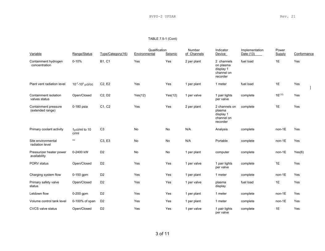
BVPS-2 UFSAR Rev. 21
3 of 11
TABLE 7.5-1 (Cont)
Qualification Number Indicator Implementation Power Variable Range/Status Type/Category(16) Environmental Seismic of Channels Device Date (13) Supply Conformance Containment hydrogen concentration
0-10% B1, C1 Yes Yes 2 per plant 2 channels on plasma display 1 channel on recorder
fuel load 1E Yes
Plant vent radiation level 10-7-105 µci/cc C2, E2 Yes Yes 1 per plant 1 meter
fuel load 1E Yes
Containment isolation valves status
Open/Closed C2, D2 Yes(12) Yes(12) 1 per valve 1 pair lights per valve
complete 1E(12) Yes
Containment pressure (extended range)
0-180 psia C1, C2 Yes Yes 2 per plant 2 channels on plasma display 1 channel on recorder
complete 1E Yes
Primary coolant activity 1µci/ml to 10
ci/ml C3 No No N/A Analysis complete non-1E Yes
Site environmental radiation level
** C3, E3 No No N/A Portable complete non-1E Yes
Pressurizer heater power availability
0-2400 kW D2 No No 1 per plant computer complete non-1E Yes(6)
PORV status Open/Closed D2 Yes Yes 1 per valve 1 pair lights
per valve complete 1E Yes
Charging system flow 0-150 gpm D2 Yes Yes 1 per plant 1 meter complete non-1E Yes Primary safety valve status
Open/Closed D2 Yes Yes 1 per valve plasma display
fuel load 1E Yes
Letdown flow 0-200 gpm D2 Yes Yes 1 per plant 1 meter complete non-1E Yes Volume control tank level 0-100% of span D2 Yes Yes 1 per plant 1 meter complete non-1E Yes CVCS valve status Open/Closed D2 Yes Yes 1 per valve 1 pair lights
per valve complete 1E Yes
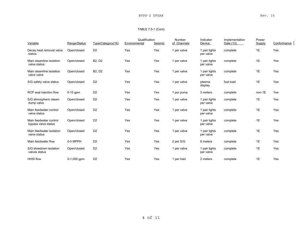
BVPS-2 UFSAR Rev. 15
4 of 11
TABLE 7.5-1 (Cont)
Qualification Number Indicator Implementation Power Variable Range/Status Type/Category(16) Environmental Seismic of Channels Device Date (13) Supply Conformance Decay heat removal valve status
Open/closed D2 Yes Yes 1 per valve 1 pair lights per valve
complete 1E Yes
Main steamline isolation valve status
Open/closed B2, D2 Yes Yes 1 per valve 1 pair lights per valve
complete 1E Yes
Main steamline isolation valve valve
Open/closed B2, D2 Yes Yes 1 per valve 1 pair lights per valve
complete 1E Yes
S/G safety valve status Open/closed D2 Yes Yes 1 per valve plasma
display fuel load 1E Yes
RCP seal injection flow 0-15 gpm D2 Yes Yes 1 per pump 3 meters complete non-1E Yes S/G atmospheric steam dump valve
Open/closed D2 Yes Yes 1 per valve 1 pair lights per valve
complete 1E Yes
Main feedwater control valve status
Open/closed D2 Yes Yes 1 per valve 1 pair lights per valve
complete 1E Yes
Main feedwater control bypass valve status
Open/closed D2 Yes Yes 1 per valve 1 pair lights per valve
complete 1E Yes
Main feedwater isolation valve status
Open/closed D2 Yes Yes 1 per valve 1 pair lights per valve
complete 1E Yes
Main feedwater flow 0-5 MPPH D2 Yes Yes 2 per S/G 6 meters complete 1E Yes S/G blowdown isolation valves status
Open/closed D2 Yes Yes 1 per valve 1 pair lights per valve
complete 1E Yes
HHSI flow 0-1,000 gpm D2 Yes Yes 1 per train 2 meters complete 1E Yes
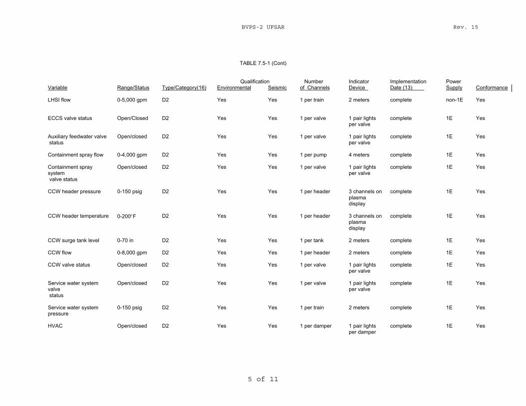
BVPS-2 UFSAR Rev. 15
5 of 11
TABLE 7.5-1 (Cont)
Qualification Number Indicator Implementation Power Variable Range/Status Type/Category(16) Environmental Seismic of Channels Device Date (13) Supply Conformance LHSI flow 0-5,000 gpm D2 Yes Yes 1 per train 2 meters complete non-1E Yes ECCS valve status Open/Closed D2 Yes Yes 1 per valve 1 pair lights
per valve complete 1E Yes
Auxiliary feedwater valve status
Open/closed D2 Yes Yes 1 per valve 1 pair lights per valve
complete 1E Yes
Containment spray flow 0-4,000 gpm D2 Yes Yes 1 per pump 4 meters complete 1E Yes Containment spray system valve status
Open/closed D2 Yes Yes 1 per valve 1 pair lights per valve
complete 1E Yes
CCW header pressure 0-150 psig D2 Yes Yes 1 per header 3 channels on
plasma display
complete 1E Yes
CCW header temperature 0-200°F D2 Yes Yes 1 per header 3 channels on
plasma display
complete 1E Yes
CCW surge tank level 0-70 in D2 Yes Yes 1 per tank 2 meters complete 1E Yes CCW flow 0-8,000 gpm D2 Yes Yes 1 per header 2 meters complete 1E Yes CCW valve status Open/closed D2 Yes Yes 1 per valve 1 pair lights
per valve complete 1E Yes
Service water system valve status
Open/closed D2 Yes Yes 1 per valve 1 pair lights per valve
complete 1E Yes
Service water system pressure
0-150 psig D2 Yes Yes 1 per train 2 meters complete 1E Yes
HVAC Open/closed D2 Yes Yes 1 per damper 1 pair lights
per damper complete 1E Yes
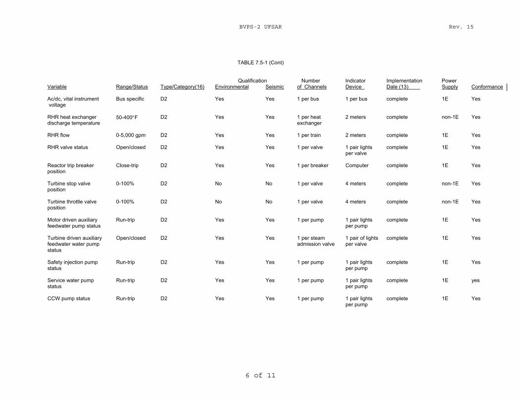
BVPS-2 UFSAR Rev. 15
6 of 11
TABLE 7.5-1 (Cont)
Qualification Number Indicator Implementation Power Variable Range/Status Type/Category(16) Environmental Seismic of Channels Device Date (13) Supply Conformance Ac/dc, vital instrument voltage
Bus specific D2 Yes Yes 1 per bus 1 per bus complete 1E Yes
RHR heat exchanger discharge temperature
50-400°F D2 Yes Yes 1 per heat exchanger
2 meters complete non-1E Yes
RHR flow 0-5,000 gpm D2 Yes Yes 1 per train 2 meters complete 1E Yes RHR valve status Open/closed D2 Yes Yes 1 per valve 1 pair lights
per valve complete 1E Yes
Reactor trip breaker position
Close-trip D2 Yes Yes 1 per breaker Computer complete 1E Yes
Turbine stop valve position
0-100% D2 No No 1 per valve 4 meters complete non-1E Yes
Turbine throttle valve position
0-100% D2 No No 1 per valve 4 meters complete non-1E Yes
Motor driven auxiliary feedwater pump status
Run-trip D2 Yes Yes 1 per pump 1 pair lights per pump
complete 1E Yes
Turbine driven auxiliary feedwater water pump status
Open/closed D2 Yes Yes 1 per steam admission valve
1 pair of lights per valve
complete 1E Yes
Safety injection pump status
Run-trip D2 Yes Yes 1 per pump 1 pair lights per pump
complete 1E Yes
Service water pump status
Run-trip D2 Yes Yes 1 per pump 1 pair lights per pump
complete 1E yes
CCW pump status Run-trip D2 Yes Yes 1 per pump 1 pair lights
per pump complete 1E Yes
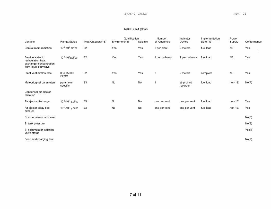
BVPS-2 UFSAR Rev. 21
7 of 11
TABLE 7.5-1 (Cont)
Qualification Number Indicator Implementation Power Variable Range/Status Type/Category(16) Environmental Seismic of Channels Device Date (13) Supply Conformance Control room radiation 10-2-103 mr/hr E2 Yes Yes 2 per plant 2 meters
fuel load 1E Yes
Service water to recirculation heat exchanger concentration from liquid pathways
10-4-101 µci/cc E2 Yes Yes 1 per pathway 1 per pathway fuel load 1E Yes
Plant vent air flow rate 0 to 75,000
SFCM E2 Yes Yes 2 2 meters complete 1E Yes
Meteorlogical parameters parameter
specific E3 No No 1 strip chart
recorder fuel load non-1E No(7)
Condenser air ejector radiation
Air ejector discharge 10-6-10-1 µci/cc E3 No No one per vent one per vent fuel load non-1E Yes Air ejector delay bed exhaust
10-6-10-1 µci/cc E3 No No one per vent one per vent fuel load non-1E Yes
SI accumulator tank level No(8) SI tank pressure No(8) SI accumulator isolation valve status
Yes(8)
Boric acid charging flow No(9)
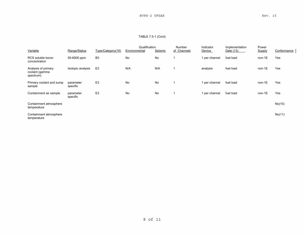
BVPS-2 UFSAR Rev. 15
8 of 11
TABLE 7.5-1 (Cont)
Qualification Number Indicator Implementation Power Variable Range/Status Type/Category(16) Environmental Seismic of Channels Device Date (13) Supply Conformance RCS soluble boron concentration
50-6000 ppm B3 No No 1 1 per channel fuel load non-1E Yes
Analysis of primary coolant (gamma spectrum)
Isotopic analysis E3 N/A N/A 1 analysis fuel load non-1E Yes
Primary coolant and sump sample
parameter specific
E3 No No 1 1 per channel fuel load non-1E Yes
Containment air sample parameter
specific E3 No No 1 1 per channel fuel load non-1E Yes
Containment atmosphere temperature
No(10)
Containment atmosphere temperature
No(11)
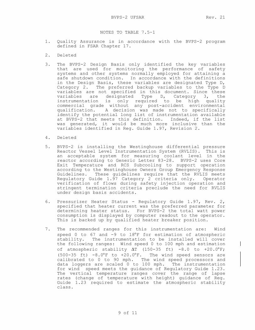
BVPS-2 UFSAR Rev. 21
9 of 11
NOTES TO TABLE 7.5-1
1. Quality Assurance is in accordance with the BVPS-2 program defined in FSAR Chapter 17.
2. Deleted 3. The BVPS-2 Design Basis only identified the key variables
that are used for monitoring the performance of safety systems and other systems normally employed for attaining a safe shutdown condition. In accordance with the definitions in the Design Basis, these variables are designated Type D, Category 2. The preferred backup variables to the Type D variables are not specified in this document. Since these variables are designated Type D, Category 3, the instrumentation is only required to be high quality commercial grade without any post-accident environmental qualification. A decision was made not to specifically identify the potential long list of instrumentation available at BVPS-2 that meets this definition. Indeed, if the list was generated, it would be much more inclusive than the variables identified in Reg. Guide 1.97, Revision 2.
4. Deleted 5. BVPS-2 is installing the Westinghouse differential pressure
Reactor Vessel Level Instrumentation System (RVLIS). This is an acceptable system for measuring coolant level in the reactor according to Generic Letter 83-28. BVPS-2 uses Core Exit Temperature and RCS Subcooling to support operation according to the Westinghouse Owners Group Emergency Response Guidelines. These guidelines require that the RVLIS meets Regulatory Guide 1.97 Category 2 criteria only. Operator verification of flows during safety injection operation and stringent termination criteria preclude the need for RVLIS under design basis accidents.
6. Pressurizer Heater Status - Regulatory Guide 1.97, Rev. 2,
specified that heater current was the preferred parameter for determining heater status. For BVPS-2 the total watt power consumption is displayed by computer readout to the operator. This is backed up by qualified heater breaker position.
7. The recommended ranges for this instrumentation are: Wind
speed 0 to 67 and -9 to 18°F for estimation of atmospheric stability. The instrumentation to be installed will cover the following ranges: Wind speed 0 to 100 mph and estimation of atmospheric stability ∆T (150-35 ft) -8.0 to +20.0°F; (500-35 ft) -8.0°F to +20.0°F. The wind speed sensors are calibrated to 0 to 90 mph. The wind speed processors and data loggers are scaled 0 to 100 mph. The instrumentation for wind speed meets the guidance of Regulatory Guide 1.23. The vertical temperature ranges cover the range of lapse rates (change of temperature with height) guidance of Reg. Guide 1.23 required to estimate the atmospheric stability class.
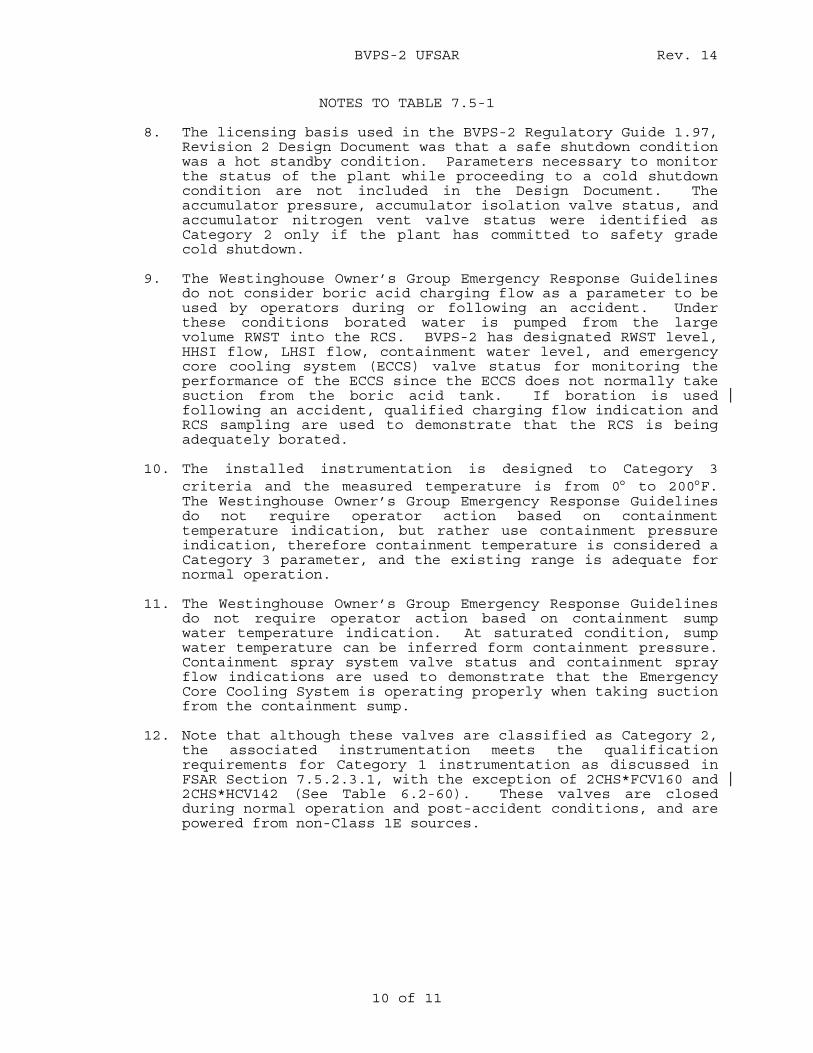
BVPS-2 UFSAR Rev. 14
10 of 11
NOTES TO TABLE 7.5-1 8. The licensing basis used in the BVPS-2 Regulatory Guide 1.97,
Revision 2 Design Document was that a safe shutdown condition was a hot standby condition. Parameters necessary to monitor the status of the plant while proceeding to a cold shutdown condition are not included in the Design Document. The accumulator pressure, accumulator isolation valve status, and accumulator nitrogen vent valve status were identified as Category 2 only if the plant has committed to safety grade cold shutdown.
9. T he Westinghouse Owner’s Group Emergency Response Guidelines
do not consider boric acid charging flow as a parameter to be used by operators during or following an accident. Under these conditions borated water is pumped from the large volume RWST into the RCS. BVPS-2 has designated RWST level, HHSI flow, LHSI flow, containment water level, and emergency core cooling system (ECCS) valve status for monitoring the performance of the ECCS since the ECCS does not normally take suction from the boric acid tank. If boration is used following an accident, qualified charging flow indication and RCS sampling are used to demonstrate that the RCS is being adequately borated.
10. The installed instrumentation is designed to Category 3
criteria and the measured temperature is from 0° to 200°F. The Westinghouse Owner’s Group Emergency Response Guidelines do not require operator action based on containment temperature indication, but rather use containment pressure indication, therefore containment temperature is considered a Category 3 parameter, and the existing range is adequate for normal operation.
11. The Westinghouse Owner’s Group Emergency Response Guidelines
do not require operator action based on containment sump water temperature indication. At saturated condition, sump water temperature can be inferred form containment pressure. Containment spray system valve status and containment spray flow indications are used to demonstrate that the Emergency Core Cooling System is operating properly when taking suction from the containment sump.
12. Note that although these valves are classified as Category 2,
the associated instrumentation meets the qualification requirements for Category 1 instrumentation as discussed in FSAR Section 7.5.2.3.1, with the exception of 2CHS*FCV160 and 2CHS*HCV142 (See Table 6.2-60). These valves are closed during normal operation and post-accident conditions, and are powered from non-Class 1E sources.
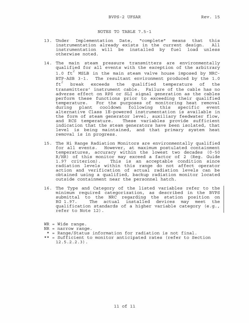
BVPS-2 UFSAR Rev. 15
11 of 11
NOTES TO TABLE 7.5-1
13. Under Implementation Date, “complete” means that this instrumentation already exists in the current design. All instrumentation will be installed by fuel load unless otherwise noted.
14. The main steam pressure transmitters are environmentally
qualified for all events with the exception of the arbitrary 1.0 ft
2 MSLB in the main steam valve house imposed by NRC-
BTP-ASB 3-1. The resultant environment produced by the 1.0 ft
2 break exceeds the qualified temperature of the
transmitters’ instrument cable. Failure of the cable has no adverse effect on RPS or SLI signal generation as the cables perform these functions prior to exceeding their qualified temperature. For the purposes of monitoring heat removal during plant cooldown following this specific event alternative Class 1E-powered instrumentation is available in the form of steam generator level, auxiliary feedwater flow, and RCS temperature. These variables provide sufficient indication that the steam generators have been isolated, that level is being maintained, and that primary system heat removal is in progress.
15. The Hi Range Radiation Monitors are environmentally qualified
for all events. However, at maximum postulated containment temperatures, accuracy within the lowest two decades (0-50 R/HR) of this monitor may exceed a factor of 2 (Reg. Guide 1.97 criterion). This is an acceptable condition since radiation levels within this range do not affect operator action and verification of actual radiation levels can be obtained using a qualified, backup radiation monitor located outside containment near the personnel hatch.
16. The Type and Category of the listed variables refer to the
minimum required categorization, as described in the BVPS submittal to the NRC regarding the station position on RG 1.97. The actual installed devices may meet the qualification standards of a higher variable category (e.g., refer to Note 12).
WR = Wide range. NR = narrow range. * = Range/Status information for radiation is not final. ** = Sufficient to monitor anticipated rates (refer to Section 12.5.2.2.3).
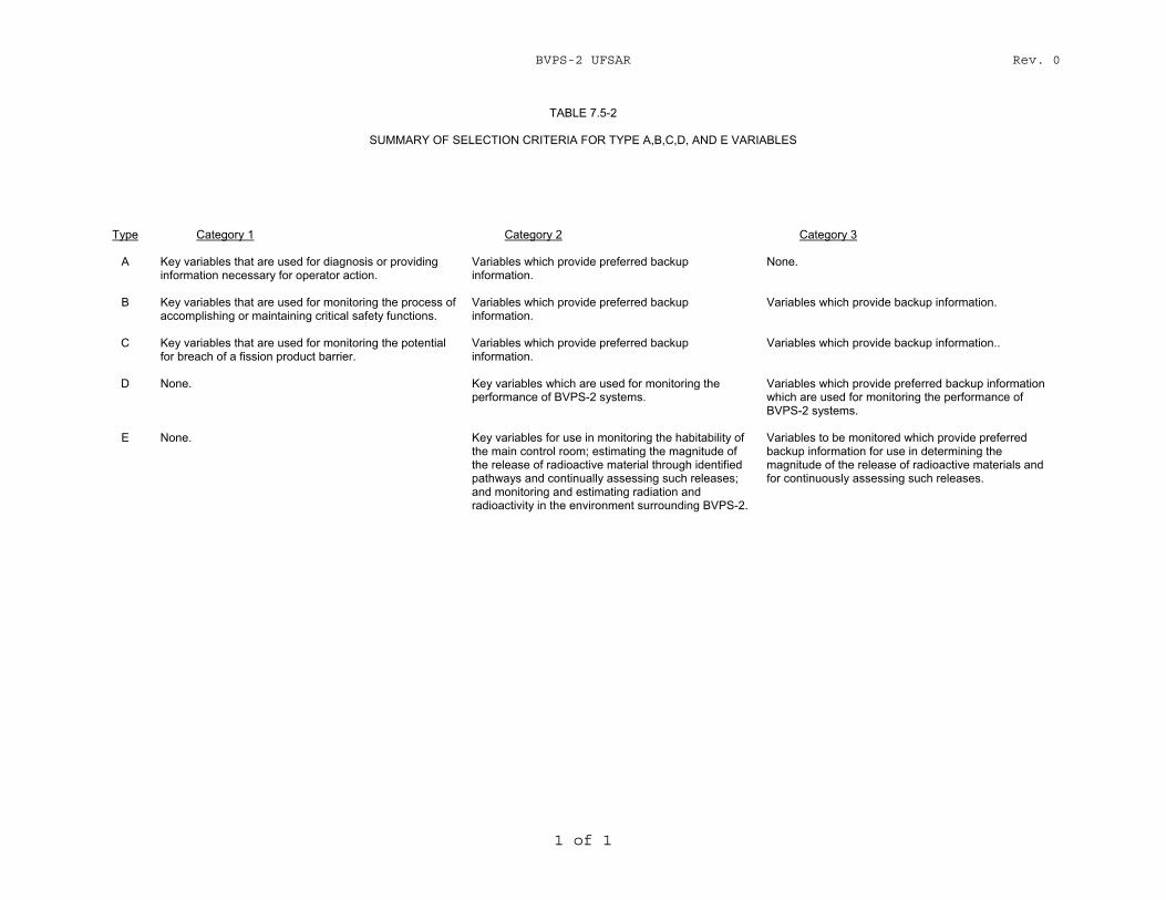
BVPS-2 UFSAR Rev. 0
1 of 1
TABLE 7.5-2
SUMMARY OF SELECTION CRITERIA FOR TYPE A,B,C,D, AND E VARIABLES Type Category 1 Category 2 Category 3
A Key variables that are used for diagnosis or providing
information necessary for operator action. Variables which provide preferred backup information.
None.
B Key variables that are used for monitoring the process of
accomplishing or maintaining critical safety functions. Variables which provide preferred backup information.
Variables which provide backup information.
C Key variables that are used for monitoring the potential
for breach of a fission product barrier. Variables which provide preferred backup information.
Variables which provide backup information..
D None. Key variables which are used for monitoring the
performance of BVPS-2 systems. Variables which provide preferred backup information which are used for monitoring the performance of BVPS-2 systems.
E None. Key variables for use in monitoring the habitability of
the main control room; estimating the magnitude of the release of radioactive material through identified pathways and continually assessing such releases; and monitoring and estimating radiation and radioactivity in the environment surrounding BVPS-2.
Variables to be monitored which provide preferred backup information for use in determining the magnitude of the release of radioactive materials and for continuously assessing such releases.

BVPS-2 UFSAR Rev. 0
1 of 1
TABLE 7.5-3
SUMMARY OF DESIGN, QUALIFICATION, AND INTERFACE REQUIREMENTS
Qualification Category 1 Category 2 Category 3
Environmental Yes As appropriate (Section 7.5.2.3.2.2)
No
Seismic Yes As appropriate
(Section 7.5.2.3.2.2)
No
Design
Single failure criterion
Yes No No
Power supply Emergency
diesel generator
Highly reliable on-site
As required (Section 7.5.2.3.3.3)
Channel-out-of-service
Technical Specifications
Technical Specifications
As required (Section 7.5.2.3.3.3)
Testability Yes Yes As required
(Section 7.5.2.3.3.3)
Interface
Minimum Immediately Demand Demand indication accessible Recording Yes As required
(Section 7.5.2.3.2.4)
As required (Section 7.5.2.3.3.4)
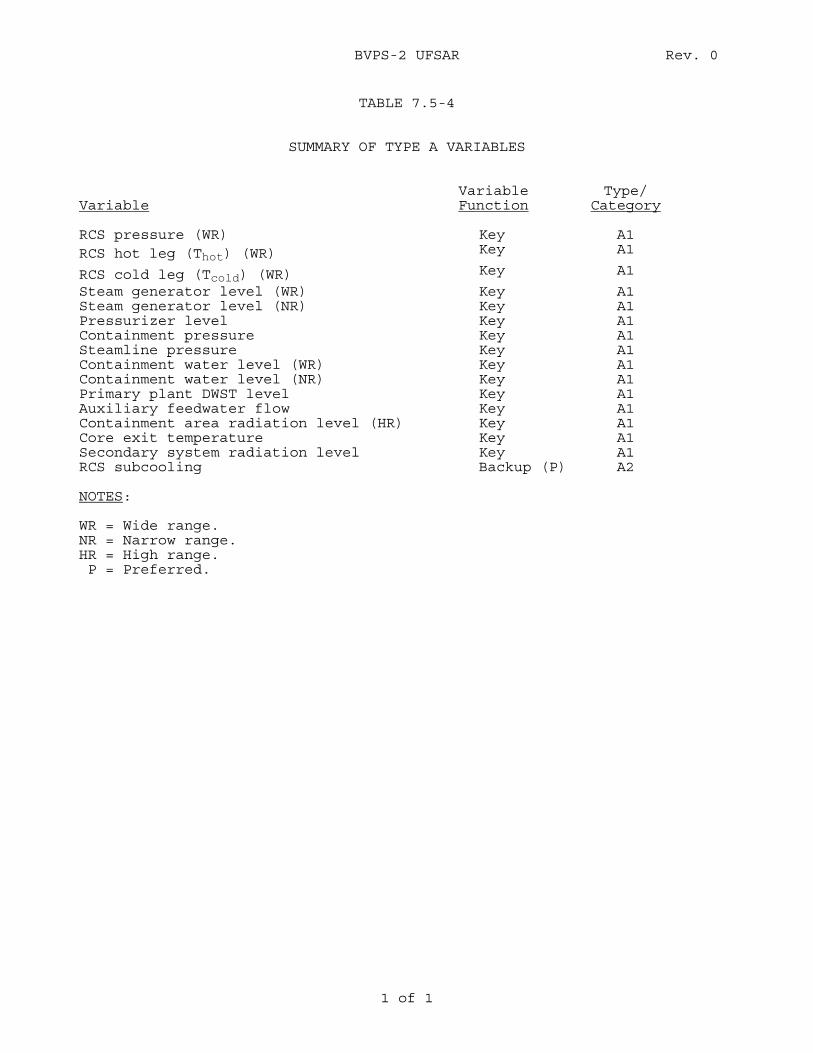
BVPS-2 UFSAR Rev. 0
1 of 1
TABLE 7.5-4
SUMMARY OF TYPE A VARIABLES
Variable
Variable Function
Type/ Category
RCS pressure (WR) Key A1 RCS hot leg (Thot) (WR) Key A1
RCS cold leg (Tcold) (WR) Key A1
Steam generator level (WR) Key A1 Steam generator level (NR) Key A1 Pressurizer level Key A1 Containment pressure Key A1 Steamline pressure Key A1 Containment water level (WR) Key A1 Containment water level (NR) Key A1 Primary plant DWST level Key A1 Auxiliary feedwater flow Key A1 Containment area radiation level (HR) Key A1 Core exit temperature Key A1 Secondary system radiation level Key A1 RCS subcooling Backup (P) A2 NOTES: WR = Wide range. NR = Narrow range. HR = High range. P = Preferred.
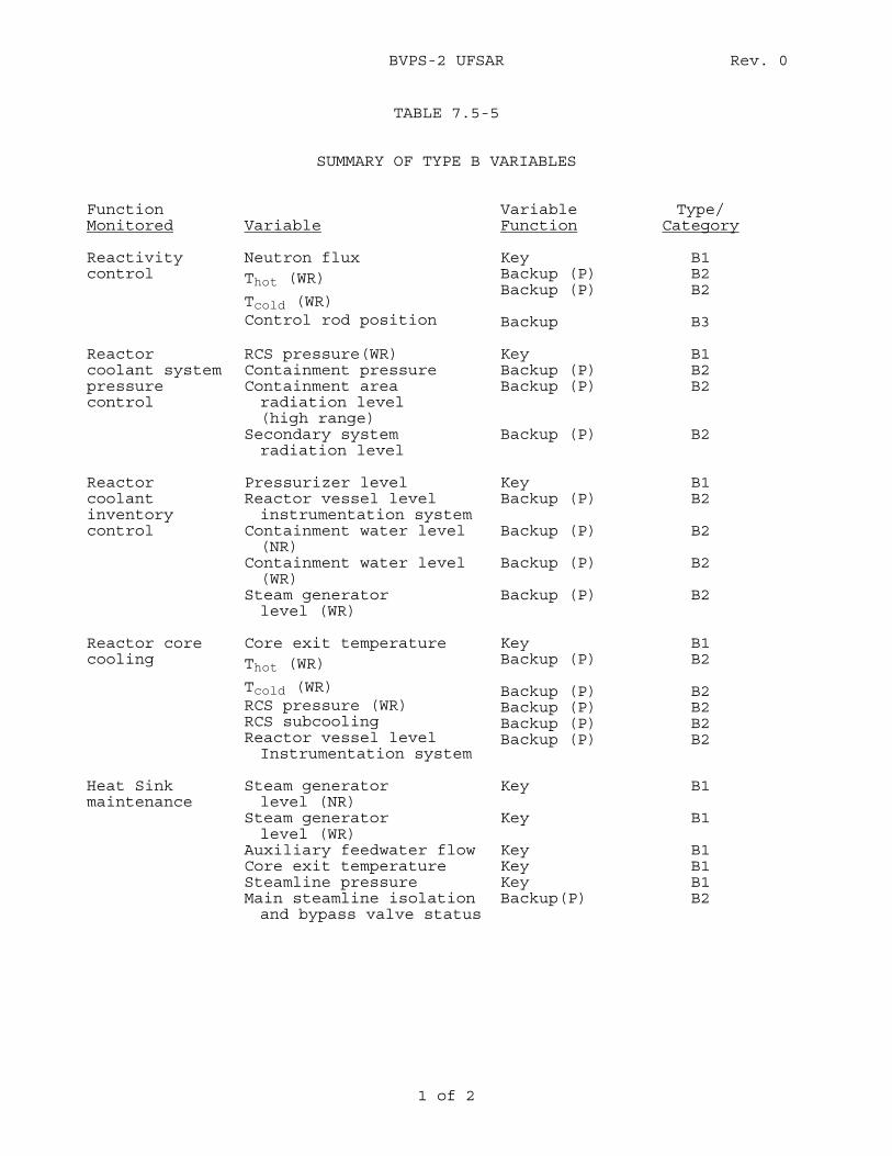
BVPS-2 UFSAR Rev. 0
1 of 2
TABLE 7.5-5
SUMMARY OF TYPE B VARIABLES
Function Monitored
Variable
Variable Function
Type/ Category
Reactivity control
Neutron flux Thot (WR)
Tcold (WR) Control rod position
Key Backup (P) Backup (P) Backup
B1 B2 B2 B3
Reactor coolant system pressure control
RCS pressure(WR) Containment pressure Containment area radiation level (high range)
Secondary system radiation level
Key Backup (P) Backup (P) Backup (P)
B1 B2 B2 B2
Reactor coolant inventory control
Pressurizer level Reactor vessel level instrumentation system
Containment water level (NR)
Containment water level (WR)
Steam generator level (WR)
Key Backup (P) Backup (P) Backup (P) Backup (P)
B1 B2 B2 B2 B2
Reactor core cooling
Core exit temperature Thot (WR)
Tcold (WR) RCS pressure (WR) RCS subcooling Reactor vessel level Instrumentation system
Key Backup (P) Backup (P) Backup (P) Backup (P) Backup (P)
B1 B2 B2 B2 B2 B2
Heat Sink maintenance
Steam generator level (NR)
Steam generator level (WR)
Auxiliary feedwater flow Core exit temperature Steamline pressure Main steamline isolation and bypass valve status
Key Key Key Key Key Backup(P)
B1 B1 B1 B1 B1 B2
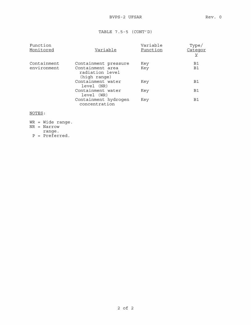
BVPS-2 UFSAR Rev. 0
2 of 2
TABLE 7.5-5 (CONT’D) Function Monitored
Variable
Variable Function
Type/ Categor
y Containment environment
Containment pressure Containment area radiation level (high range)
Containment water level (NR)
Containment water level (WR)
Containment hydrogen concentration
Key Key Key Key Key
B1 B1 B1 B1 B1
NOTES: WR = Wide range. NR = Narrow range. P = Preferred.
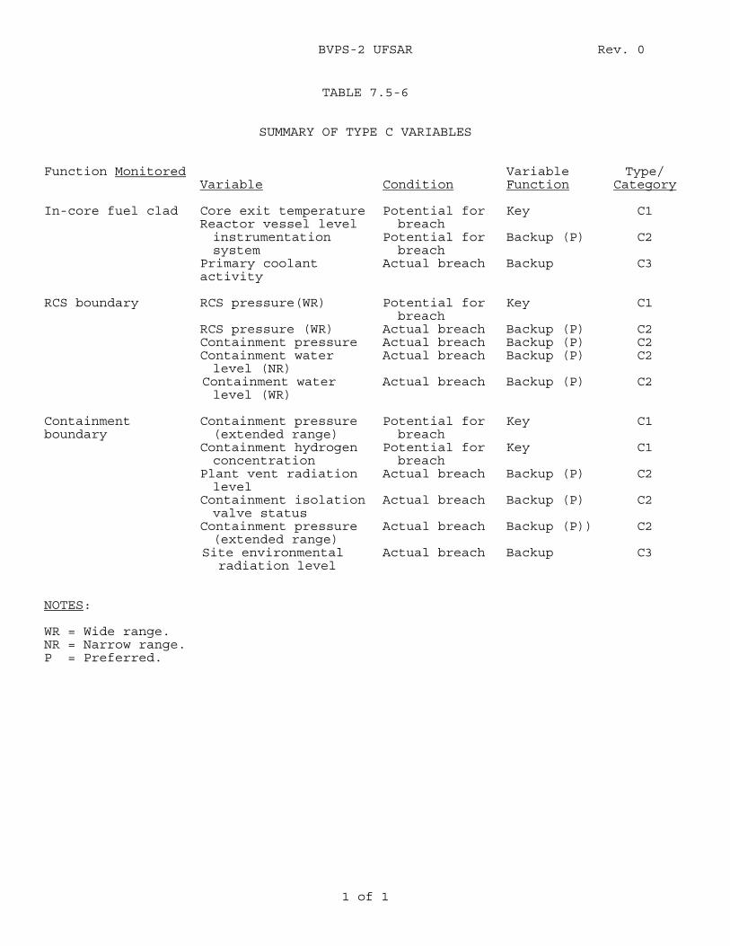
BVPS-2 UFSAR Rev. 0
1 of 1
TABLE 7.5-6
SUMMARY OF TYPE C VARIABLES
Function Monitored Variable
Condition
Variable Function
Type/ Category
In-core fuel clad Core exit temperature
Reactor vessel level instrumentation system
Primary coolant activity
Potential for breach
Potential for breach
Actual breach
Key Backup (P) Backup
C1
C2
C3
RCS boundary RCS pressure(WR)
RCS pressure (WR) Containment pressure Containment water level (NR)
Containment water level (WR)
Potential for breach
Actual breach Actual breach Actual breach Actual breach
Key Backup (P) Backup (P) Backup (P) Backup (P)
C1
C2 C2 C2
C2
Containment boundary
Containment pressure (extended range)
Containment hydrogen concentration
Plant vent radiation level
Containment isolation valve status
Containment pressure (extended range)
Site environmental radiation level
Potential for breach
Potential for breach
Actual breach Actual breach Actual breach Actual breach
Key Key Backup (P) Backup (P) Backup (P)) Backup
C1
C1
C2
C2
C2
C3
NOTES: WR = Wide range. NR = Narrow range. P = Preferred.
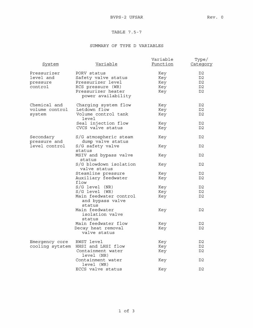
BVPS-2 UFSAR Rev. 0
1 of 3
TABLE 7.5-7
SUMMARY OF TYPE D VARIABLES
System
Variable Variable Function
Type/ Category
Pressurizer level and pressure control
PORV status Safety valve status Pressurizer level RCS pressure (WR) Pressurizer heater
power availability
Key Key Key Key Key
D2 D2 D2 D2 D2
Chemical and volume control system
Charging system flow Letdown flow Volume control tank
level Seal injection flow CVCS valve status
Key Key Key
Key Key
D2 D2 D2 D2 D2
Secondary pressure and level control
S/G atmospheric steam dump valve status
S/G safety valve status MSIV and bypass valve status
S/G blowdown isolation valve status
Steamline pressure Auxiliary feedwater flow S/G level (NR) S/G level (WR) Main feedwater control
and bypass valve status
Main feedwater isolation valve status
Main feedwater flow Decay heat removal
valve status
Key
Key
Key
Key
Key Key
Key Key Key
Key
Key Key
D2 D2 D2 D2 D2 D2 D2 D2 D2
D2 D2 D2
Emergency core cooling sytstem
RWST level HHSI and LHSI flow Containment water
level (NR) Containment water
level (WR) ECCS valve status
Key Key Key
Key
Key
D2 D2 D2 D2 D2
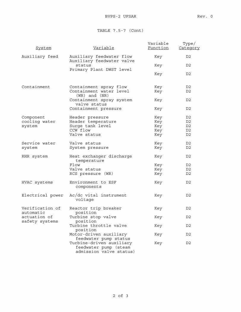
BVPS-2 UFSAR Rev. 0
2 of 3
TABLE 7.5-7 (Cont)
System
Variable
Variable Function
Type/ Category
Auxiliary feed Auxiliary feedwater flow
Auxiliary feedwater valve status
Primary Plant DWST level
Key
Key
Key
D2 D2 D2
Containment Containment spray flow
Containment water level (WR) and (NR)
Containment spray system valve status
Containment pressure
Key Key
Key
Key
D2 D2 D2 D2
Component cooling water system
Header pressure Header temperature Surge tank level CCW flow Valve status
Key Key Key Key Key
D2 D2 D2 D2 D2
Service water system
Valve status System pressure
Key Key
D2 D2
RHR system Heat exchanger discharge
temperature Flow Valve status RCS pressure (WR)
Key
Key Key Key
D2 D2 D2 D2
HVAC systems Environment to ESF
components Key D2
Electrical power Ac/dc vital instrument
voltage Key D2
Verification of automatic actuation of safety systems
Reactor trip breaker position
Turbine stop valve position
Turbine throttle valve position
Motor-driven auxiliary feedwater pump status
Turbine-driven auxiliary feedwater pump (steam admission valve status)
Key
Key
Key
Key
Key
D2 D2 D2 D2 D2
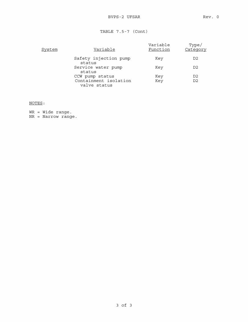
BVPS-2 UFSAR Rev. 0
3 of 3
TABLE 7.5-7 (Cont)
System
Variable
Variable Function
Type/ Category
Safety injection pump
status Service water pump
status CCW pump status Containment isolation
valve status
Key
Key
Key Key
D2 D2 D2 D2
NOTES: WR = Wide range. NR = Narrow range.
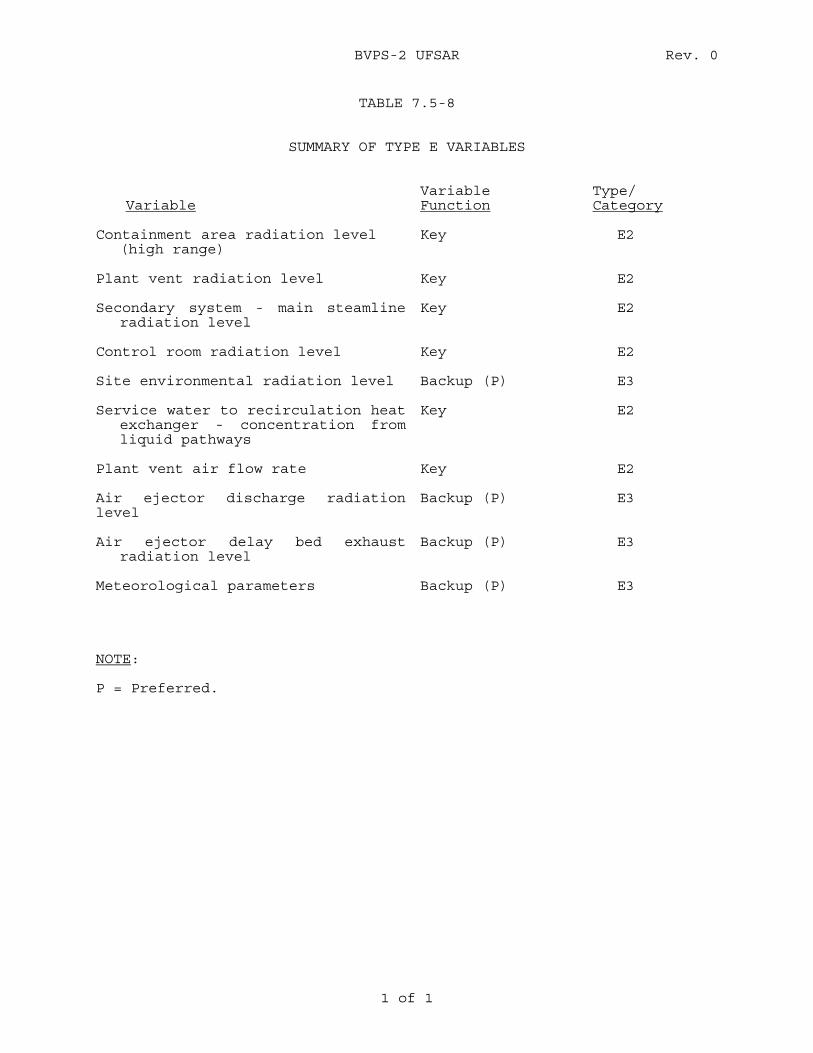
BVPS-2 UFSAR Rev. 0
1 of 1
TABLE 7.5-8
SUMMARY OF TYPE E VARIABLES
Variable Variable Function
Type/ Category
Containment area radiation level
(high range) Key E2
Plant vent radiation level Key E2 Secondary system - main steamline
radiation level Key E2
Control room radiation level Key E2 Site environmental radiation level Backup (P) E3 Service water to recirculation heat
exchanger - concentration from liquid pathways
Key E2
Plant vent air flow rate Key E2 Air ejector discharge radiation level
Backup (P) E3
Air ejector delay bed exhaust
radiation level Backup (P) E3
Meteorological parameters Backup (P) E3 NOTE: P = Preferred.
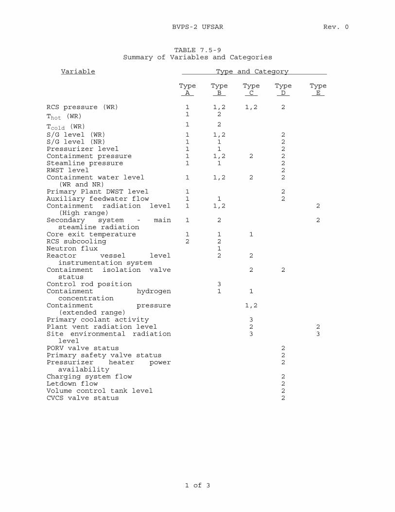
BVPS-2 UFSAR Rev. 0
1 of 3
TABLE 7.5-9 Summary of Variables and Categories
Variable Type and Category
Type A
Type B
Type C
Type D
Type E
RCS pressure (WR) 1 1,2 1,2 2 Thot (WR) 1 2
Tcold (WR) 1 2
S/G level (WR) 1 1,2 2 S/G level (NR) 1 1 2 Pressurizer level 1 1 2 Containment pressure 1 1,2 2 2 Steamline pressure 1 1 2 RWST level 2 Containment water level
(WR and NR) 1 1,2 2 2
Primary Plant DWST level 1 2 Auxiliary feedwater flow 1 1 2 Containment radiation level
(High range) 1 1,2 2
Secondary system - main steamline radiation
1 2 2
Core exit temperature 1 1 1 RCS subcooling 2 2 Neutron flux 1 Reactor vessel level
instrumentation system 2 2
Containment isolation valve status
2 2
Control rod position 3 Containment hydrogen
concentration 1 1
Containment pressure (extended range)
1,2
Primary coolant activity 3 Plant vent radiation level 2 2 Site environmental radiation
level 3 3
PORV valve status 2 Primary safety valve status 2 Pressurizer heater power
availability 2
Charging system flow 2 Letdown flow 2 Volume control tank level 2 CVCS valve status 2
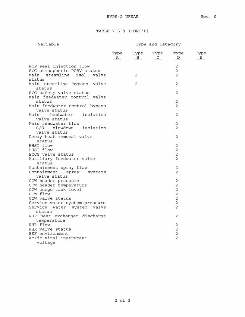
BVPS-2 UFSAR Rev. 0
2 of 3
TABLE 7.5-9 (CONT’D)
Variable Type and Category
Type A
Type B
Type C
Type D
Type E
RCP seal injection flow 2 S/G atmospheric PORV status 2 Main steamline isol valve status
2 2
Main steamline bypass valve status
2 2
S/G safety valve status 2 Main feedwater control valve
status
2
Main feedwater control bypass valve status
2
Main feedwater isolation valve status
2
Main feedwater flow 2 S/G blowdown isolation valve status
2
Decay heat removal valve status
2
HHSI flow 2 LHSI flow 2 ECCS valve status 2 Auxiliary feedwater valve status
2
Containment spray flow 2 Containment spray systems
valve status 2
CCW header pressure 2 CCW header temperature 2 CCW surge tank level 2 CCW flow 2 CCW valve status 2 Service water system pressure 2 Service water system valve
status 2
RHR heat exchanger discharge temperature
2
RHR flow 2 RHR valve status 2 ESF environment 2 Ac/dc vital instrument voltage
2
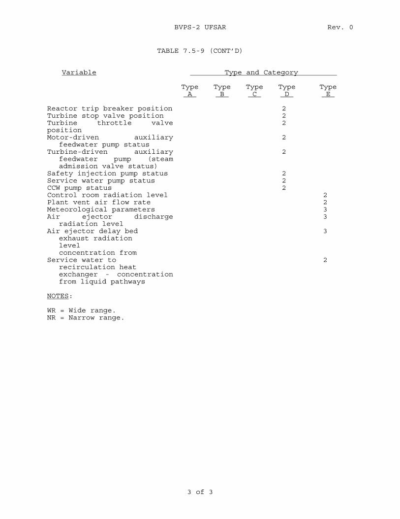
BVPS-2 UFSAR Rev. 0
3 of 3
TABLE 7.5-9 (CONT’D)
Variable Type and Category
Type A
Type B
Type C
Type D
Type E
Reactor trip breaker position 2 Turbine stop valve position 2 Turbine throttle valve position
2
Motor-driven auxiliary feedwater pump status
2
Turbine-driven auxiliary feedwater pump (steam admission valve status)
2
Safety injection pump status 2 Service water pump status 2 CCW pump status 2 Control room radiation level 2 Plant vent air flow rate 2 Meteorological parameters 3 Air ejector discharge
radiation level 3
Air ejector delay bed exhaust radiation level concentration from
3
Service water to recirculation heat exchanger - concentration from liquid pathways
2
NOTES: WR = Wide range. NR = Narrow range.
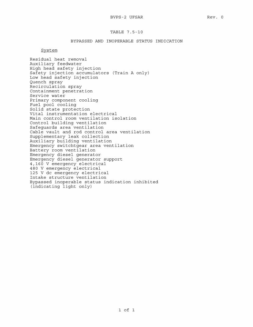
BVPS-2 UFSAR Rev. 0
1 of 1
TABLE 7.5-10
BYPASSED AND INOPERABLE STATUS INDICATION
System Residual heat removal Auxiliary feedwater High head safety injection Safety injection accumulators (Train A only) Low head safety injection Quench spray Recirculation spray Containment penetration Service water Primary component cooling Fuel pool cooling Solid state protection Vital instrumentation electrical Main control room ventilation isolation Control building ventilation Safeguards area ventilation Cable vault and rod control area ventilation Supplementary leak collection Auxiliary building ventilation Emergency switchtgear area ventilation Battery room ventilation Emergency diesel generator Emergency diesel generator support 4,160 V emergency electrical 480 V emergency electrical 125 V dc emergency electrical Intake structure ventilation Bypassed inoperable status indication inhibited (indicating light only)
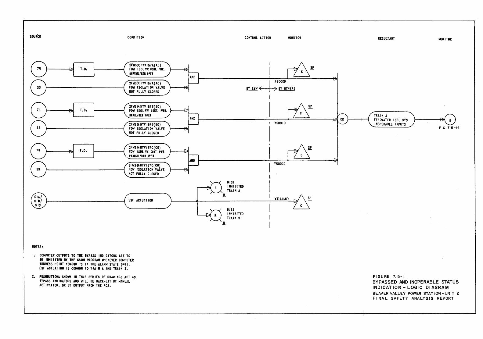
sou ICE
T .0.
T.D.
T.D.
NOTES:
CONDITION
2FWS~HYV157A(AO) FOW I SOL V¥. COU. Pll. UNAYAIL/111 OPEl
2FWS ~ HYV 157.1.{ AO) FDW ISOLATION VALVE NOT FULLY CLOSED
2FWS * HYV 157B( BO) FDW I SOL YY. COlT. PIR. UUIL/BIR OPEl
2FWS* HYV 157B( BO) FDW ISOLATION VALVE NOT FULLY CLOSED
2FWS ~HYV 157C( CO) FDW I SOL VY. COlT. PIR. UIAVAI L/ BlR OPE I
2FWS~HYV157C(CO) FDW ISOLATION VALVE NOT FULLY CLOSED
ESF ACTUATION
I, COMPUTER OUTPUTS TO THE BYPASS INDICATORS ARE TO BE I Nil I B I TED BY THE SSON PROGRAM WIIENEVER CtlofPUTER ADDRESS POINT YOijO~D IS IN THE ALARM STATE (=1). ESF ACTUATION IS COMMON TO TRAIN A AND TRAIN B.
2. PUSHBUTTON~ SHOWN IN THIS SERIES OF DRAWINGS ACT AS BYPASS INDICATORS AND WILL BE BACK-LIT BY MANUAL ACTIVATION, OR BY OUTPUT FROM THE PCS.
!.
BISI INHIBITED TRAIN A
BISI INHIBITED TRAIN B
CONTROL ACT I ON 1>40NITOR
l Y5000D ~~BY OTHERS
I Y5001D
Y5002D
Y0404D
RESULTANT
TRAIN A FEEDWATER ISOL SYS INOPERABLE INPUTS
FIGURE 7.5-1
OITOI
FIG. 7.5-14
BYPASSED AND INOPERABLE STATUS INDICATION- LOGIC 01 AGRAM BEAVER VALLEY POWER STATION- UNIT 2 FINAL SAFETY ANALYSIS REPORT
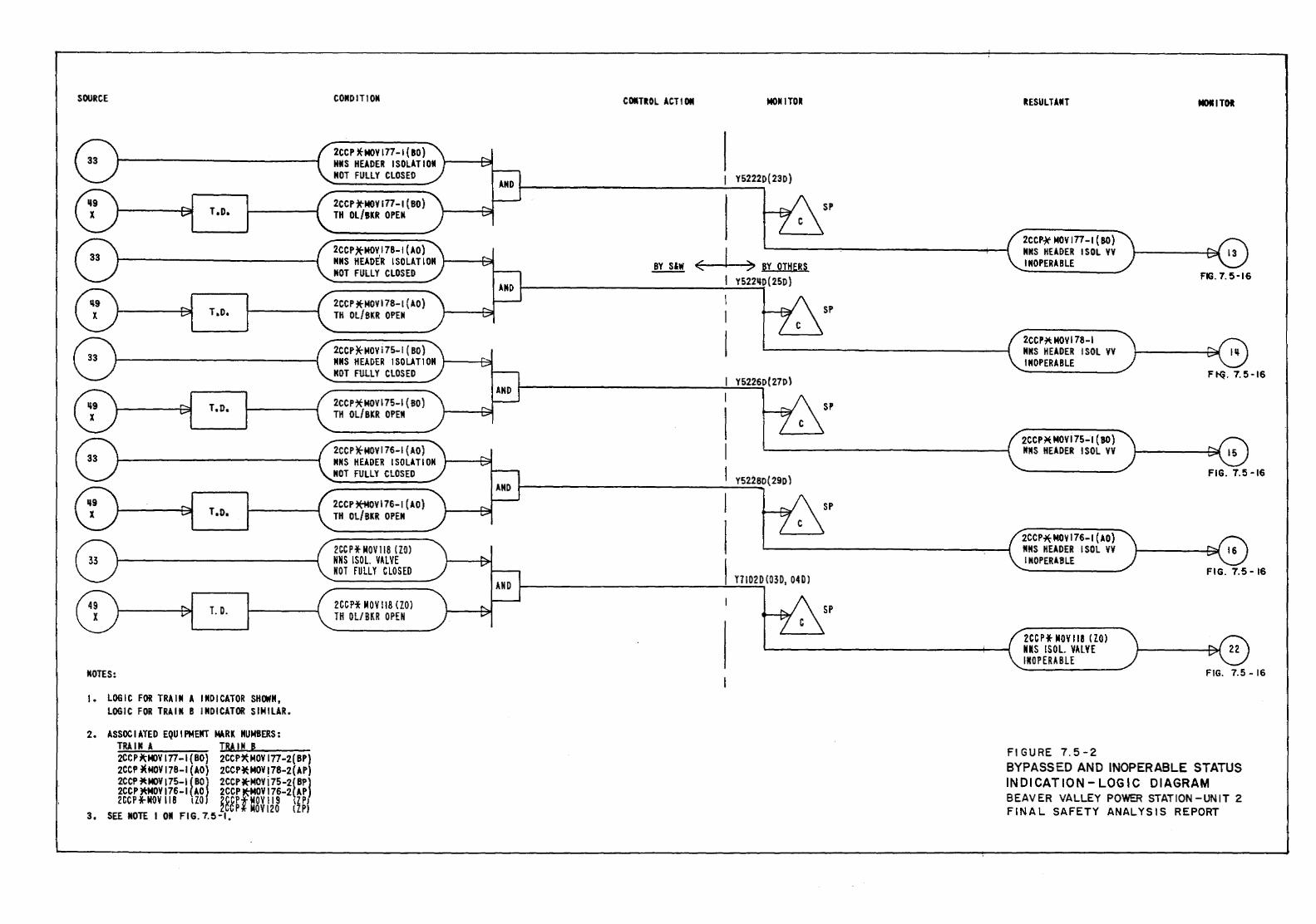
SOURCE
T .D.
T .o.
T.o.
T.o.
T. D.
NOTES:
1. LOGIC FOR TRAIN A INDICATOR SHOWN, LOGIC FOR TRAIN B INDICATOR SIMILAR.
2. ASSOC lA TED EQU I PMENT MlRK NUMBERS : T~IM A T~M~IN~B ______ _ 2CC P ~MOV 177 -I ( 80) 2CCP~ MDV 177 -2( BP) 2CCP *MDV 178-1 (AD) 2CCP*:MOV 178-2(AP) 2CCP i't:MOV 175-1 ( BDJ 2CCP.MOVj 75-2{ BP) 2CCP~OV!76-I(AD 2CCP~MOV176-2{AP) 2CCPf.MOVII8 1ZO ~~&PfMOV119 IZPJ
3, SEE MOTE I 011 FIG. 7.5-1, p MOVI 20 lZPI
CONDITION C'*lii:OL ACT I 011
2CCP )E-MOV 177-1 { 80) MMS HEADER ISOLATION NOT FULLY CLOSED
2CCP*NOY177-1 (BO) TH OL/BKR OPEN
2CCPjrMOVI78-I(AO) NilS HEADER ISOLATION .!!..!!! NOT FULLY CLOSED
2CCP *MDV 178-1 {AD) TH OL/BKR OPEN
2CCP*MOV 175-1 ( BO) NNS HEADER ISOL.ATIOH NOT FULLY CLOSED
2CCP:*MOVI75-1 {BO) TH OL/BKR OPEN
2CCP*MOVI76-1 {AO) NilS HEADER ISOLATION NOT FULLY CLOSED
2CCP~OVI76-I(AO) TH OL/BKR OPEN
2CC P* MOV 118 {ZOl NNS !SOL VALVE NOT fUllY CLOSED
2CCP* MOV 118 { ZOl TH Ol/ BlR OPEN
MONITOR
I Y5222D( 23D)
SP
( :;> ~y OTH~R~ Y522110(25D)
SP
Y5226D(27D)
SP
Y52280(290)
SP
Y7102D {03D, 04D J
SP
RESULTANT **ITOI
2CCP-)t MDV 177-1 (SO) NilS HEADER !SOL VV INOPERABLE
FIG. 7. 5-16
2CCP~ MDV 178 -I NilS HEADER !SOL YV INOPERABLE
Ftq. 7.5-16
2CCP~ MOVI75-I { 80) NilS HEADER !SOL VV
FIG. 7.5-16
2CCP* MDV 176-1 (AD} 11115 HEADER !SOL VY I MOPERA BL.E
FIG. 7.5-16
2CC P* MOY 118 { ZO) NIS !SOL VAlVE I MOP ERA Bl£
FIG. 7.5- 16
F I G U RE 7. 5 - 2 BYPASSED AND INOPERABLE STATUS INDICATION-LOGIC DIAGRAM BEAVER VALLEY POWER STATION-UNIT 2 FINAL SAFETY ANALYSIS REPORT
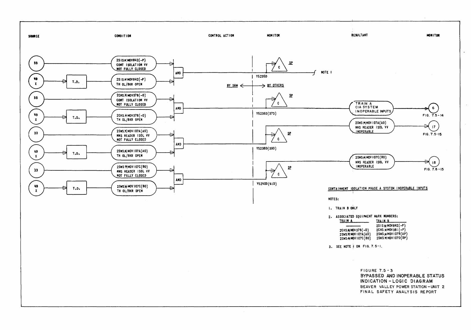
SMCE
r.o,
T,D,
T,O,
T,o,
COMO IT ION
2S IS* MOY8~2( -P) COHT ISOLATION VY NOT FULLY CLOSED
2S 1 S ~ MOY8~2( -P) TH OL/BKR OPEN
2CHS * MOV378 ( -0) COHT ISOLATION VV MOT FULLY CLOSED
2CHS x-MOV378 ( -0) TH OL/BKR OPEN
2SWS ~MDV I 07A { AO) NNS HEADER !SOL VV NOT FULLY CLOSED
2SWS:* MDV I 07A( AD) TH OL/BKR OPEN
2SWS;tMOVI07C{BO) NNS HEADER !SOL VV NOT FULLY CLOSED
2S'IIS~MOVI07C{BO) TH Ol/BKR OPEN
COMTR OL ACTI ON MOM IT OR MO•ITOI
MOTE I Y52350
BY S&W 7 BY OTHERS
Y5236D{ 370)
Y5238D(39D)
TRAIN A CIA SYSTEM INOPERABLE INPUTS
2SWS~MOVI07A{AO) MMS HEADER ISOL VV M P RABLE
FIG. 7.5-14
FIG. 7.5-16
; 2SWS~MOVI07C(BO) .------------------1 MMS HEADER ISOL VV
Y5211-0D(IliD)
INOPERABLE FIG. 7.5-.!5
COMTAIMMEMT ISOLATION PHASE A SYSTEM INOPERABLE INPUTS
MOTES:
2. ASSOCIATED EQUIPMENT MARK NUMBERS: TRAIN A T.LilR.a.A L.lll N.....~B~--
2CHS*MOV 378( -0) 2SWS*MOV I 07A(AO) 2SWS'*MOVI07C(BO)
25 I S*MOV81l2( -P) 2CHS Jt-MOV381 ( -P) 2SWS~MOVI07B(AP) 2SWS *MDV I 070( BP)
3. SEE MOTE il ON FIG. 7. 5 -!.
FIGURE 7.5-3 BYPASSED AND INOPERABLE STATUS INDICATION- LOG\ C DIAGRAM BEAVER VALLEY POWER STATION -UNIT 2 FINAL SAFETY ANALYSIS REPORT
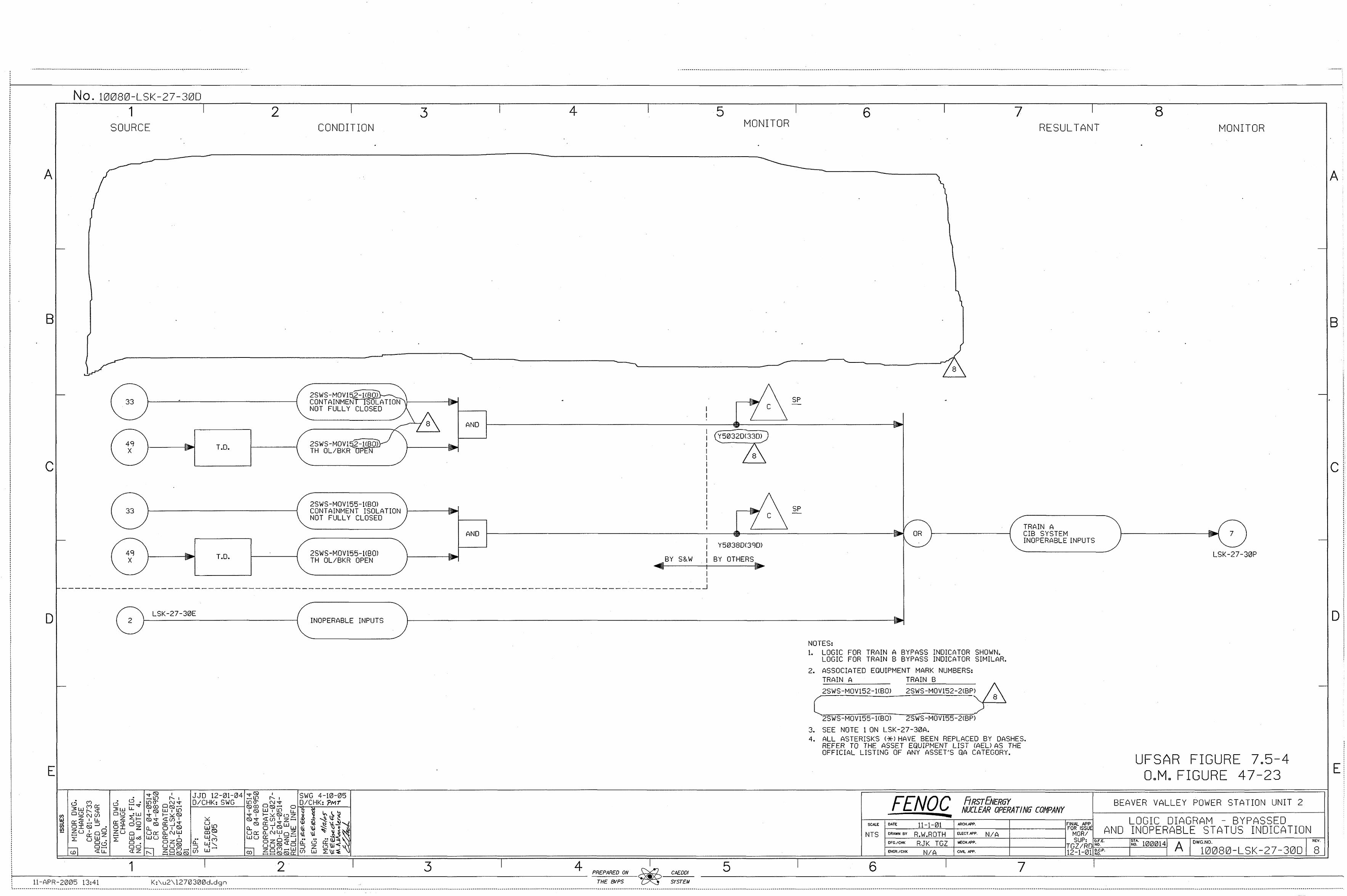
.
A
B
c
D
E
-
-
No. 10080-LSk-27-300 1
SOURCE
33
49 X
33
49 X
I 2
T.D.
T.D.
-------------------------------------------------------------------------------------------------------------------------------------------------------------·---------------------------------------------------,--- ---
I
CONDITION 3 I 4 I 5
MONITOR
2SWS-MOV15Z· HBOii-CONTAINMEN~ !_SOLA TI~ ""' ""'
I 6
SP NOT FULLy CLOSED \ I\ .... f----, I 7 c
j8\ AND ~----------------------~--~~======~---------~~ I I (t'5032D(33DJ)
2SWS-MOV152-HBOV ""' 1 1\ TH OL/BKR UI-'EN .... I ·. I 8 \
2SWS-MOV155-l<BO> CONTAINMENT ISOLATION NOT FULLY CLOSED
2SWS-MOV165-1<80) TH Ol/BKR OPEN
.. ... AND
... ....
I I I I I I I I """ SP I 7 C I If
~-------------------~·-~._~====~-----------~~~ OR I I I
""'BY S&W . 1 lllllli! i
I I
Y5038DC3CJO)
BY OTHERS .. .,. 1'-..___,
I 7 I
RESULTANT
TRAIN A CIB SYSTEM INOPERABLE INPUTS
8 MONITOR
-
-
7 -LSK-27-30P
-------------------------------------------------------------------------------------------------~
LSK-27-30E 2 INOPERABLE INPUTS
1--
-NOTES: l. LOGIC FOR TRAIN A BYPASS INDICATOR SHOWN.
LOGIC FOR TRAIN B BYPASS INDICATOR SIMILAR. 2. ASSOCIATED EQUIPMENT MARK NUMBERS:
TRAIN A TRAIN B
2SWS-MOV152-2<BPl .~
[~~~~-=~~~ 2SWS-MOV155-HBOl 2SWS-MOV155-2<BPl
2SWS-MOV152-HBOl
3. SEE NOTE 1 ON LSK-27-30A. 4. All ASTERISKS <*lHAVE BEEN REPLACED BY DASHES.
REFER TO THE ASSET EQUIPMENT LIST CAEU AS THE OFFICIAL LISTING OF ANY ASSET'S QA CATEGORY.
FENOC RRSTENERGY NUCLEAR OPERATING COMPANY
SCALE FINAL APP. 1-----=---"-'=---t------+------lFOR ISSUE
DATE 11-1-01 ARCH . .6PP.
DRAWN BY £LECT.AF'P. MGR/
-
UFSAR FIGURE 7.5-4 O.M. FIGURE 47-23
BEAVER VALLEY POWER STATION UNIT 2
LOGIC DIAGRAM - BYPASSED AND INOPERABLE STATUS INDICATION NTS
~--~~~~-----+-----~TG~~RO~~"~•~---,.~~~-l-0_0_0_14,--A-r-o=wc~.N~o-.------------,,"~"v~. 12-1-01 ~g-P. 10080-LSK-27-30D 8
R.W.ROTH N/A DF"G.ICHI< RJK TGZ MECH.~.
ENGR.ICHK N/A CIVIL M'P.
I 7 I i-------------1 _______ 1 _______ 2 _______ 1
______ 3 _______ 1 _______ 4_ PRePAReD ON ~ CA£001
ll-APR-2005 13:41 K:\u2\l270300d.dgn THe ENP$ ~ SfSTeM
5 I 6
A
B
c
D
E
---K------------------------•••••••••••-----------------------------•••••••••-------------------•••••••••O•o•••••••••••·------•••••••••••••••••••••••••••••••••••••••••••••••••••••••·------------••••••••••••••OoOOOOO __________________________________________ OO•OO•O••••••••OO•OOO•••••••••••••••••••••·---------------------------------•••••••••••••••••oOOoOOOO•O•o••••••••••oOOOO••••••••O••••••••••••••••••••••••••••••••••••·-------••••OOoo•••••••••••••••••••-----------••••••••••••••••••·-------------------------•••••••••••••••••--------------------••••••••----------••••••••••••------------•••••••••••0000•••••••••••••••••--------------------------·----.
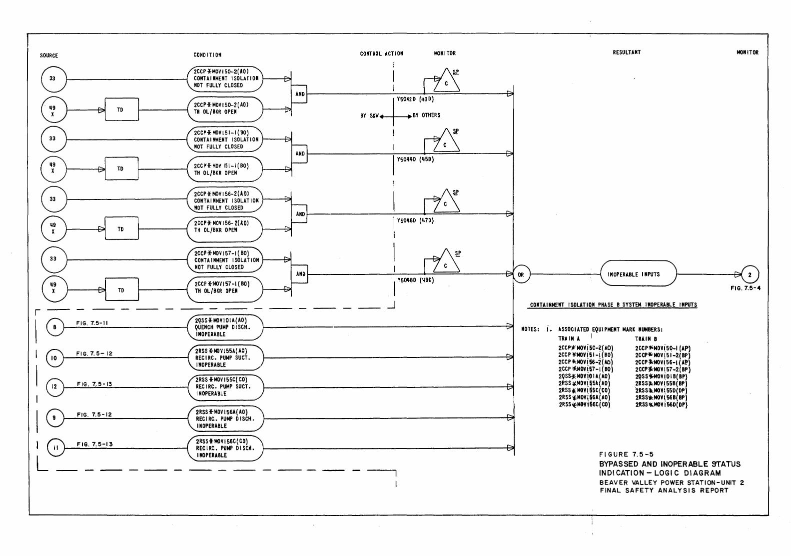
SOURCE
TD
TO
TO
TO
r
I FIG. 7.5-11
FIG. 7. 5- 12
FIG. 7.5-13
FIG. 7.5-12
FIG. 7.5-13
COHO ITI ON
2CCP *MDV I S0-2(AO) CONTAINMENT ISOLAfiOM 1---~ NOT FULLY CLOSED
2CCP* MOV 150-2 (AD) TH OL/BKR OPEN
2CC~* MOV I 51-1 ( BO) CONT A I NMENT I SO LA Tl 0 N 1-----Plil NOT FULLY CLOSED
2CCP'*MDV 151-I(BO} TH OL/BKR OPEN
2CCP * MOV 156-2 (A 0) CONTA I MMENT I SOL AT I OM ~-~ MOT FULLY CLOSED
2CCP* MDV I 56- 2( A 0) TH OL/BKR OPEN
2CC1"*MOV I 57-1 ( BO) CONTA 1 NMEMT I SOLA Tl OM 1---~ MOT FULLY CLOSED
2CCP *MDV 157-l ( BO) TH OL/BKR OPEN
2QSS *MDV I 0 l A{ AO) QUENCH PUMP DISCH. INOPERABLE
2RSS -l-MO V !55A( AD) RECIRC. PUMP SUCT. INOPERABLE
2RSS *MOVI55C( CO) RECIRC. PUMP SUCT. INOPERABLE
2RSS *:MDV 156A{ AD} RECIRC. PUMP DISCH. INOPERABLE
2RSS *MDV 156C {CO) RECIRC. PUMP DISCH. INOPERABLE
CONTROL ACliON t«lNITOR
I I Y504Z 0 (q3 D)
BY S&W~BY OTHERS
I Y50~~D (ll50)
1 Y501l60 ( ~70)
I
I I Y501J.BD ( ll9D)
_j
RESULTANT MONITOR
INOPERABLE INPUTS
FIG. 7.5-4
CONTAINMENT ISOLATION PHASE B SYSTEM INOPERABLE INPUTS
NOTES: 1. ASSOCIATED EQUIPMENT MARK NUMBERS: TRAIN A i TRAIN B 2CCP~ MOY! 50-?( AO) 2CC P 'I': MDV~ 50-l ( AP) 2CCP *MOY!51-! {BO) 2CCP4:MOY!51-2(BP) 2CC P ~NOV! Ss-2 ( A.O) 2CCP J:M()y 1. 56-J (A!'} 2CCP :fd40V !57-I ( BO) 2CCP~MOY! 57 -2{ BP) 2QSS*MOY!O I A( AD) 2QSS~V I_ 0 I B( BP) 2RSS ~MDV! ~SA ( AO) ,2RSSJ.,MOY! 558 ( BP) 2RSS j( MDV! SSC( CO} 2RSS4.MOY! 550( DP) 2RSS *MOV!$6A(AO) 2RSSW::MOY! 568( BP) 2RSS~MOYI56C(CO) 2RSS~MOYI56D(DP}
Fl GURE 7.5-5 BYPASSED AND INOPERABLE STATUS INDICATION- LOG! C DIAGRAM BEAVER VALLEY POWER STATION-UNIT 2 FINAL SAFETY ANALYSIS REPORT
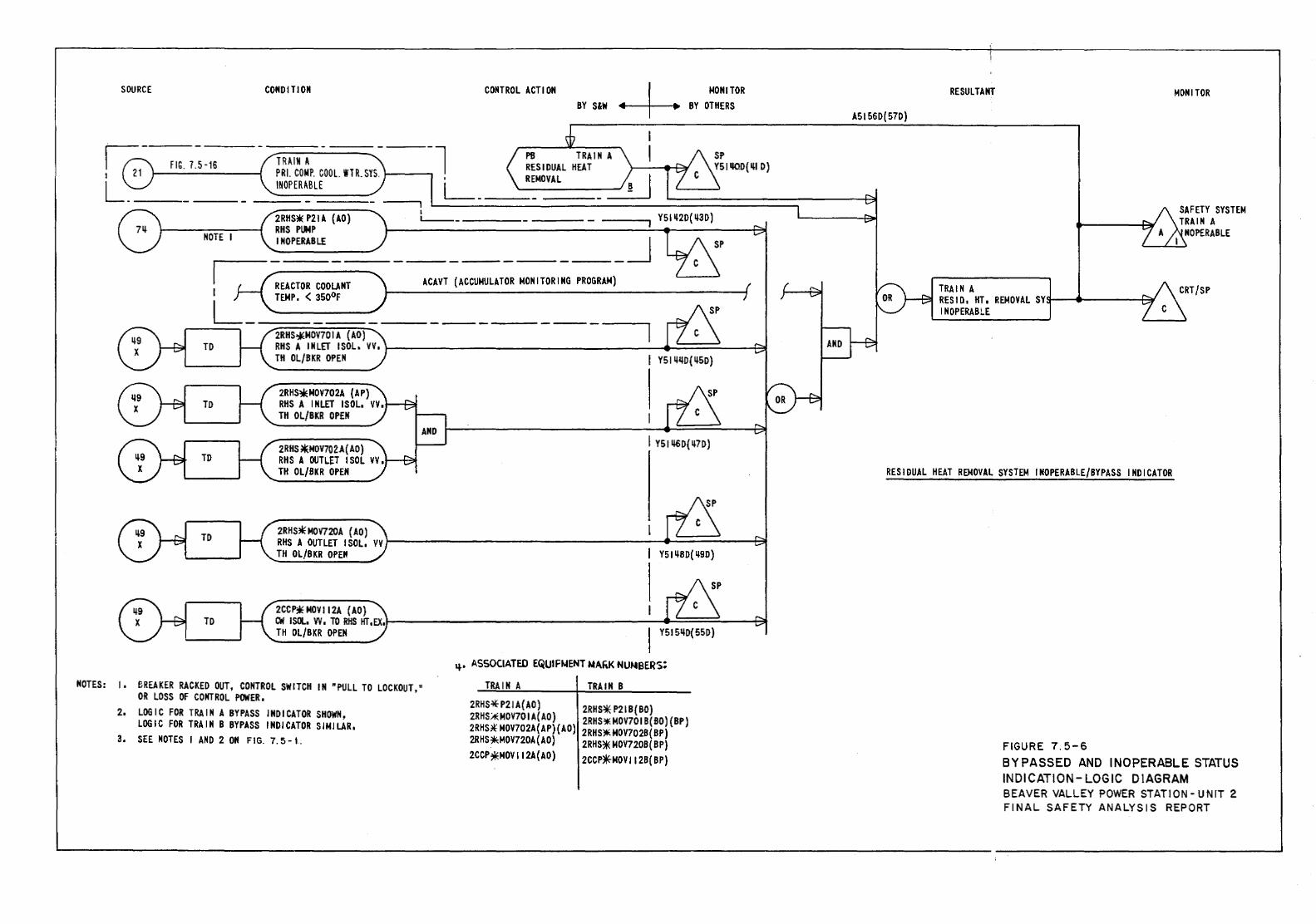
SOURCE
FIG. 7.5-16
NOTE I
CONDITION CONTROL ACTI ON BY S&W
TRAIN .A. 1-----.-l PB TRAIN A RESIDUAL HEAT PRI. COMP. COOL. WTR. SYS. , REMOVAL INOPERABLE L---~=-----
2RHS* P21 A (AD) RHS PUMP INOPERABLE
I t._ ____ _
I REACTOR COOLANT I TEMP, < 350°F
ACAVT (ACCUMULATOR MONITORING PROGRAM)
L- ---=:::::=:::..;:::;:;::::::;:~::::: ----------- - --------.
MONITOR BY OTHERS
2RHS~MOV701A (AD) RHS A INLET I SOL. VV, \.-----------------___:---4t-..:=====----~
TO
TO
TH OL/BKR OPEN
2RHS*MOV702A (AP) RHS A INLET ISOL, VV, TH OL/BKR OPEN
2RHS *MOV702.A( AD) RHS A OUTLET ISOL VV, TH OL/BKR OPEN
NOTES: 1. flREAKER RACKED OUT, CONTROL SWITCH IN "PULL TO LOCKOUT," OR LOSS OF CONTROL POWER,
2, LOGIC FOR TRAIN A BYPASS INDICATOR SHOWN, LOGIC FOR TRAIN B BYPASS INDICATOR SIMILAR,
3, SEE NOTES I AND 2 ON FIG. 7. 5 -I.
I YSI ij6Q( ~70)
YSI ~80( ~90)
Y515ij0(550)
q.. ASSOCIATED EQUIFt.tENT NA"K NUMBERS:
TRAIN A TRAIN B
2RHS-lfP21 A(AO) 2RHS* P21 B( BO) 2RHS.Aii_MOV70 I A(AD) 2RHS'* MOV701 B( SO) {BP) 2RHS*" MOV702A(AP) (AD) ZRHS)Ir<MDV702B(BP) 2RHS?ir<:MOV720A(AO} 2RHS* MOV720B( BP) 2CCP~MOVII2A(AD) 2CCP~MOVII2B(BP)
RESULTANT MONITOR
A5156D(57D)
TRAIN A RESID, HT, REMOVAL SYs--t-----+3t' INOPERABLE
RESIDUAL HEAT REMOVAL SYSTEM INOPERABLE/BYPASS INDICATOR
FIGURE 7. 5-6 BYPASSED AND INOPERABLE STATUS INDICATION- LOGIC DIAGRAM BEAVER VALLEY POWER STATION- UNIT 2 FINAL SAFETY ANALYSIS REPORT
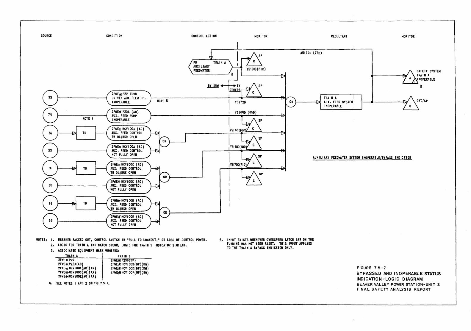
SOURCE
MOTE I
TO
TD
TD
CONDITION
2HiE* P22 TURB DRIVEN AUX FEED PP. INOPERABLE
2FWE* P23A (AO) AUX I FEED PUMP INOPERABLE
2FWE* HCV I OOA ( AO) AUX, FEED CONTROL TH OL/BKR OPEN
2FWE* HCV I OOA ( AO) AUX, FEED CONTROL NOT FULLY OPEN
2FWE* HCV I OOC (AD) AUX. FEED CONTROL TH OL/BRK OPEN
2FW~ HCV!OOC {AO) AUX. FEED CONTROL NOT FULLY OPEN
2FW~ HCVIOOE {AO) AUX. FEED CONTROL TH OL/BKR OPEN
2FWE~HCVIOOE (AO) AUX, FEED CONTROL NOT FULLY OPEN
CONTROL ACT I ON
NOTES: 1. BREAKER RACKED OUT, CONTROL SWITCH IN "PULL TO LOCKOUT,ft OR LOSS OF ~ONTROL POWER. 2. LOGIC FOR TRAIN A INDICATOR SHOWN, LOGIC FOR TRAIN B INDICATOR SIMILAR. 3. ASSOCIATED EQUIPMENT MARK NUMBERS:
TRAIN A 2FWE*P22 2FWE* P23A(AO) 2FWE-* HCV I OOA(AO) ( AR) 2FWE~HCVtOOC{AO)(AR) 2FWE~HCVIOOE(AO)(AR)
ll, SEE NOTES I AND 2 ON FIG. 7.5-1,
TRAIN B 2FWE'* P23B( BP) 2FWE~HCVIOOB{BP)(BW) 2FWE~HCVIOOD(BP){BW) 2FWE~HCVIOOF(BP){BW)
MO_NITOR
A51720 (73D)
RESULTANT
TRAIN A J
AUX. FEED SYST91 INOPERABLE
MONITOR
SAFETY SYSTEM TRAIN A INOPERABLE
I
AUXILIARY FEEDWATER SY$TEM INOPERABLE/BYPASS INDICATOR
5. INPUT EXISTS WHENEVER OVERSPEED LATCH BAR ON THE TURBINE KAS NOT BEEN RESET. THIS INPUT APPLIES TO THE TRAIN A BYPASS INDICATOR ONLY.
FIGURE 7.5-7 BYPASSED AND INOPERABLE STATUS INDICATION -LOGIC D lA GRAM BEAVER VALLEY POWER STAT ION-UNIT 2 FINAL SAFETY ANALYSIS REPORT
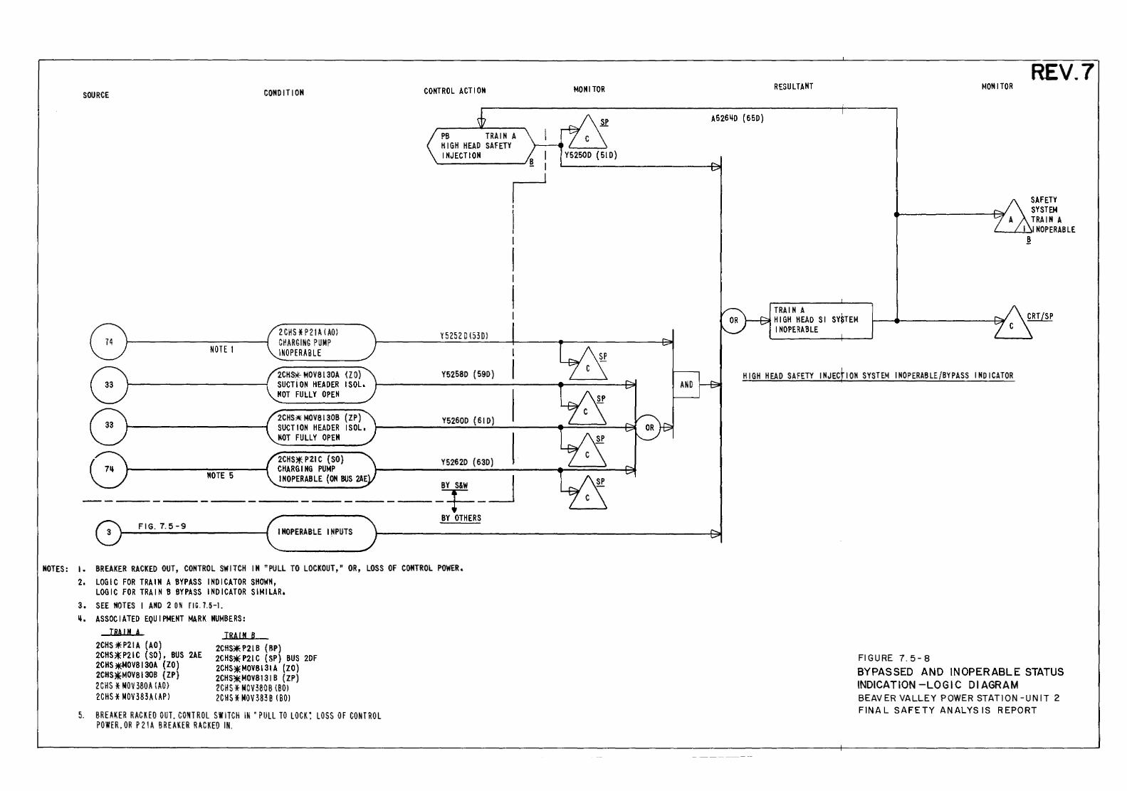
SOURCE
NOTE 1
MOTE 5
CONDIT I OM
lCHS *Pl1 ~ l ~0) CH~RGING PUMP INOPER~B LE
2CHS* MOV 8130A (l 0) SUCTiON HEADER !SOL. NOT FULLY OPEN
2CHS:* MOV8130B (ZP) SUCTION HEADER !SOL, NOT FULLY OPEN
2CHS*- P21 C (SO) CHARGING PUMP INOPERABLE (ON BUS 2AE
CONTROL ACTION
PB TRAIN A HIGH HEAD SAFETY INJECTION I
I
I I
1 I
I
I I
f
Y 5252 D 1530}
Y5258D (59D)
Y5260D (61D)
Y5262D {63D)
-----BY S&W _j ------1=--BY OTHERS
FIG. 7.5-9 INOPERABLE INPUTS
NOTES : I • BREAKER RACKED OUT, CONTROL SWITCH I H "PULL TO LOCKOUT, n OR, LOSS OF CONTROL POWER. 2. LOGIC FOR TRAIN A BYPASS INDICATOR SHOWN,
LOGIC FOR TRAIN B BYPASS INDICATOR SIMILAR, 3, SEE NOTES I AND 2 0 II FIG. 7.5-1. ~. ASSOCIATED EQUIPMENT MARK NUMBERS:
TRAIN A 2CHS*P21A (AO) 2CHS*P21C (SO), BUS 2AE 2CHS~OV8130A (ZO) 2CHS~MOV8130B (ZP) 2 CHS * MOV 380~ lAO) lCHS * MOV 383A ( ~p 1
TRAIN B 2CHS* P2l B ( BP) 2CHS*P21C {SP) BUS 2DF 2CHS* MOV8131 A (ZO) 2CHS*.MOV8131 B (ZP) 2CH S * MOV 380 B lBO I 2CHS * MOV 383 B l BOI
5. BREAKER R~CKEO OUT, CONTROL SWITCH IN' PULL TO LOCK: LOSS OF CONTROL POWER, OR P 21 A BREAKER RACKED IN.
MONITOR
A526~0 ( 65D)
RESULTANT
TRAIN A HIGH HEAD Sl SY~TEM INOPERABLE
MONITOR REV.7
SAFETY SYSTEM TRAIN A
~~~~INOPERABLE
~
HIGH HEAD SAFETY INJECfiON SYSTEM INOPERABLE/BYPASS INDICATOR
FIGURE 7.5-8 BYPASSED AND INOPERABLE STATUS INDICATION -LOGIC Dl AGRAM BEAVER VALLEY POWER STATION -UN IT 2 FINAL SAFETY ANALYSIS REPORT
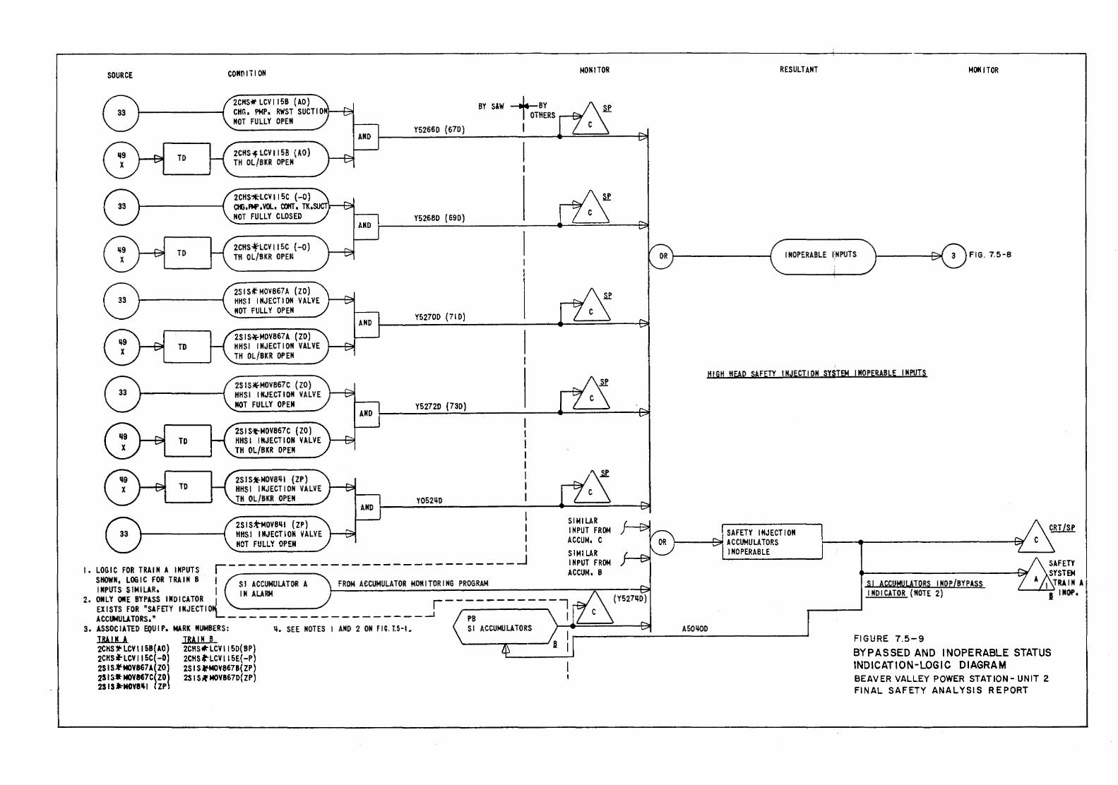
SOURCE
TO
TO
TO
CONOITION
2CHS. LCV IISB (AD) CHA, PMP, RWST SUCTION NOT FULLY OPEN
2CHS--fLCVII58 {AO) TH OL/BKR OPEN
2CHS~LCVIISC (-0) a«J,f'M',VOL, COKT. TK, NOT FULLY CLOSED
2CHS~LCVII5C {-o) TH OL/BKR OPEN
2S I Slf M0¥867 A (IO) HHSI INJECTION VALVE NOT FULLY OPEN
2SIS~MOV867A {ZO) HHSI INJECTION VALVE TH OL/BKR OPEN
2SIS~MOV867C {ZO) HHSI INJECTION VALVE NOT FULLY OPEN
2SIS~MOV867C (ZO) HHSI INJECTION VALVE TH OL/BKR OPEN
2SIS*MOV8ql {ZP) HHS I I MJECT l ON VALVE TH OL/BKR OPEN
2SIS~OV8ql {ZP) HHSI INJECTION VALVE NOT FULLY OPEN
BY S&W .....J._BY TeTHERS
Y52660 (670) I
Y5268D (690)
Y52700 {71 D)
Y5272D (730}
Y052qo
I I I I
1. LOGIC FOR TRAIN A INPUTS ~----------------------------_j
MONITOR
SIMILAR INPUT FROM ACCUM, C SIMILAR INPUT FROM ACCUM. B
SHOWN, LOGIC FOR TRAIN B I Sl ACCUMULATOR A FROM ACCUMULATOR MONITORING PROGRAM INPUTS SIMILAR, I 1M ALARM ~:.:.:.:.::...:.:.:..:.:.:.:::.::.::..;,.,:.:::...:.:.:~...:.:.:....:...:.....:..:.:..~,;__---------,~-----t?j
2. ONLY OtiE BYPASS INDICATOR {_ r-----------~ EXISTS FOR wSAFETY INJECTIO ACCII4UUTORS,w --------------- ____ _! PB I
3. ASSOCIATED EQUIP. MARK NUMBERS: q, SEE MOTES I AND 2 OM fiG.1.5·1. Sl ACCUMULATORS \.-~===--~~
RESULTANT MOH I TOR
INOPERABLE ~NPUTS FIG. 7.5-8
HIGH HEAD SAFEJY INJECTION SYSTEM INOPERABLE INPUTS
SAFETY INJECTION !------+~ACCUMULATORS
INOPERABLE
A5QqQD
Sl ACCUMULATORS INOP{BYPASS INDICATOR (MOTE 2)
T!U.!N A TRAIN B t---------------------' FIGURE 7.5-9 2CHS1' LCV II SB{AO) 2CHSI:' LCV II SO( BP) 2CHS,W.LCVIISC{-O) 2CHS ... LCVIISE{-P) 2SIS~MOV867A(ZO} 2SIS~MOVB67B(ZP) 2S IS .. MOV867C( ZO) 2S IS It M0¥8670{ ZP) 2S IS.M0¥8~1 l ZP\
BYPASSED AND INOPERABLE STATUS INDICATION-LOGIC DIAGRAM BEAVER VALLEY POWER STATION- UNIT 2 FINAL SAFETY ANALYSIS REPORT
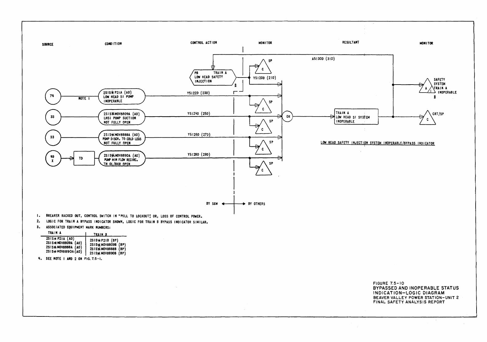
SOURCE
NOTE I
TD
COMO ITION
2SIS*P21J.. (AO) LOW HEAD S I PUMP INOPERABLE
2SJS~MOV8809A (AO) LHSI PUMP SUCTION MOT FULLY OPEN
2SIS;EMOV8888A (AO) PlMP DISCH. TO COLD tmS NOT FULLY OPEN
2SI~MOV8890A (AO) PUoF MIN Fl.O!rf RECIRC,
TH OL BKR OPEN
CONTROL ACTION
PB TRAIN A LOW HEAD SAFETY INJECTION
YSI22D (230)
Y5124-D ( ZSD)
Y5126D { 27D)
Y5128D {290)
MONITOR
YSI200 {210)
I I
I I
I • 2. 3.
BY S&W
BREAKER RACKED OUT, CONTROL SWITCH IN "PULL TO LOCKOUT~ OR, LOSS OF CONTROL POWER. LOGIC FOR TRAIN A BYPASS INDICATOR SHOWN, LOGIC FOR TRAIN B BYPASS INDICATOR SIMILAR. ASSOCIATED EQUIPMENT NARK NUMBERS:
+BY OTHERS
TRAIN A 2StS* P21A (AO) 2SIS~MOV8809A (AO) 2SIS~NOY8888A (AO) 2S IS* MOY8890A ( AO)
2SIS~P21B {SP) 2SIS~MOY8809B (BP) 2SIS~MOY8888B {BP) 2S IS* MOV 88908 { BP)
q. SEE NOTE I AND 2 011 FIG. 7.5 -I.
RESULTANT
ASI300 (310)
TRAIN A l--------+3l!LOW HEAD Sl SYStEM
INOPERABLE
MOM I TOll:
SAFETY SYSTEM TRAIN A
....___.._........._. INOPERABLE I
LOW HEAD SAFETY IMJECTIPN SYSTEM INOPERABLE{BYPASS INDICATOR
FIGURE 7.5-10 BYPASSED AND INOPERABLE STATUS INDICATION-LOGIC DIAGRAM BEAVER VALLEY POWER STATION-UNIT 2 FINAL SAFETY ANALYSIS REPORT
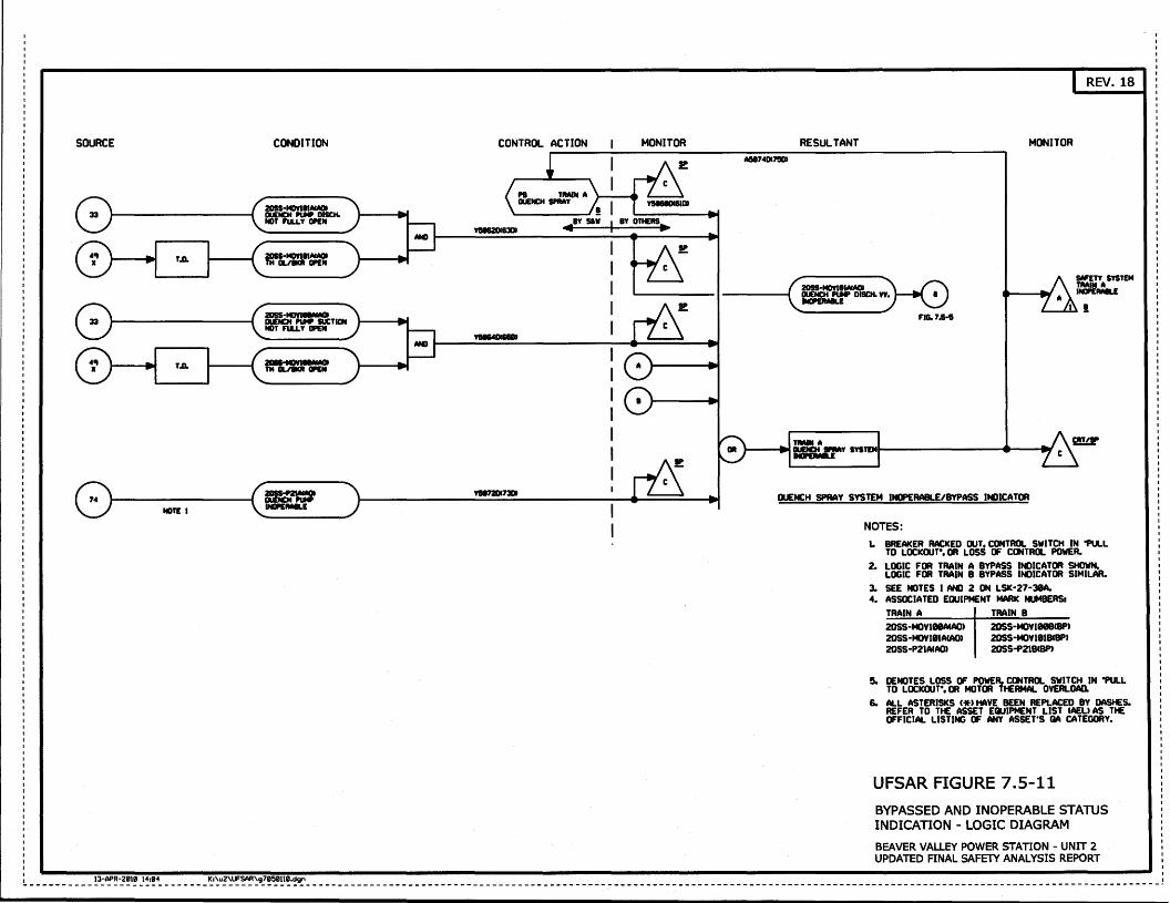
SOURCE
NOTE I
CONDITION
20SS-MDYIIIACAOI llUEIICH ....... DISCH. NOT Fu.LY c:ft:N
20SS·MDYIIIACAOI TH 01../IICR c:ft:N
CONTROL ACTION MONITOR A!11174DI7!101
RESULTANT
20SS-MDYIIIACAOI DUEIICH ....... DISCH. yy, INDI'£R4IILE
REV. 18
MONITOR
FIG.7.1-t
Dl.ENCH SPRAY SYSTEM INOPERABLE/BYPASS INDICATOR
NOTES: 1. BREAKER RACKED OUT, CONTROL SWITCH IN "PULL
TO LDCICOUT", DR LOSS OF CONTROL POWER. 2. LOGIC FOR TRAIN A BYPASS INDICATOR SHOWN.
LOGIC FOR TRAIN B BYPASS INDICATOR SIMILAR. 3. SEE NOTES I AND 2 ON LSIC-27·31A. 4. ASSOCIATED EQUIPMENT MARIC NlMERSI
TRAIN A 20SS-MOVIIIIIAW» 20SS-MOVIIIACAQ) 20SS·P21AlAOJ
TRAIN B 20SS·MOV1118(8P) 20SS·MOV1118CBPt 20SS·P218CBP)
So DENOTES LOSS OF POWER. CONTROL SWITCH IN "PU..L TO LDCI(OIJT", DR MOTOR Tt£RMAL OVERLOAD.
6. ALL ASTERISICS C*t HAVE BEEN REPLACED BY DASt£S. REFER TO Tt£ ASSET EQUIPMENT LIST IAEU AS Tt£ OFFICIAL LISTING OF ANY ASSET'S QA CATEGORY.
UFSAR FIGURE 7.5-11 BYPASSED AND INOPERABLE STATUS INDICATION - LOGIC DIAGRAM
BEAVER VALLEY POWER STATION - UNIT 2 UPDATED FINAL SAFElY ANALYSIS REPORT
I
__________ ~3.:1!~--2~1! _1~•!4_ _______ ~~~u~~~~,!'~9!~!_1!·~ _______________________________________________________________________________________ • _____________________________________________ ;
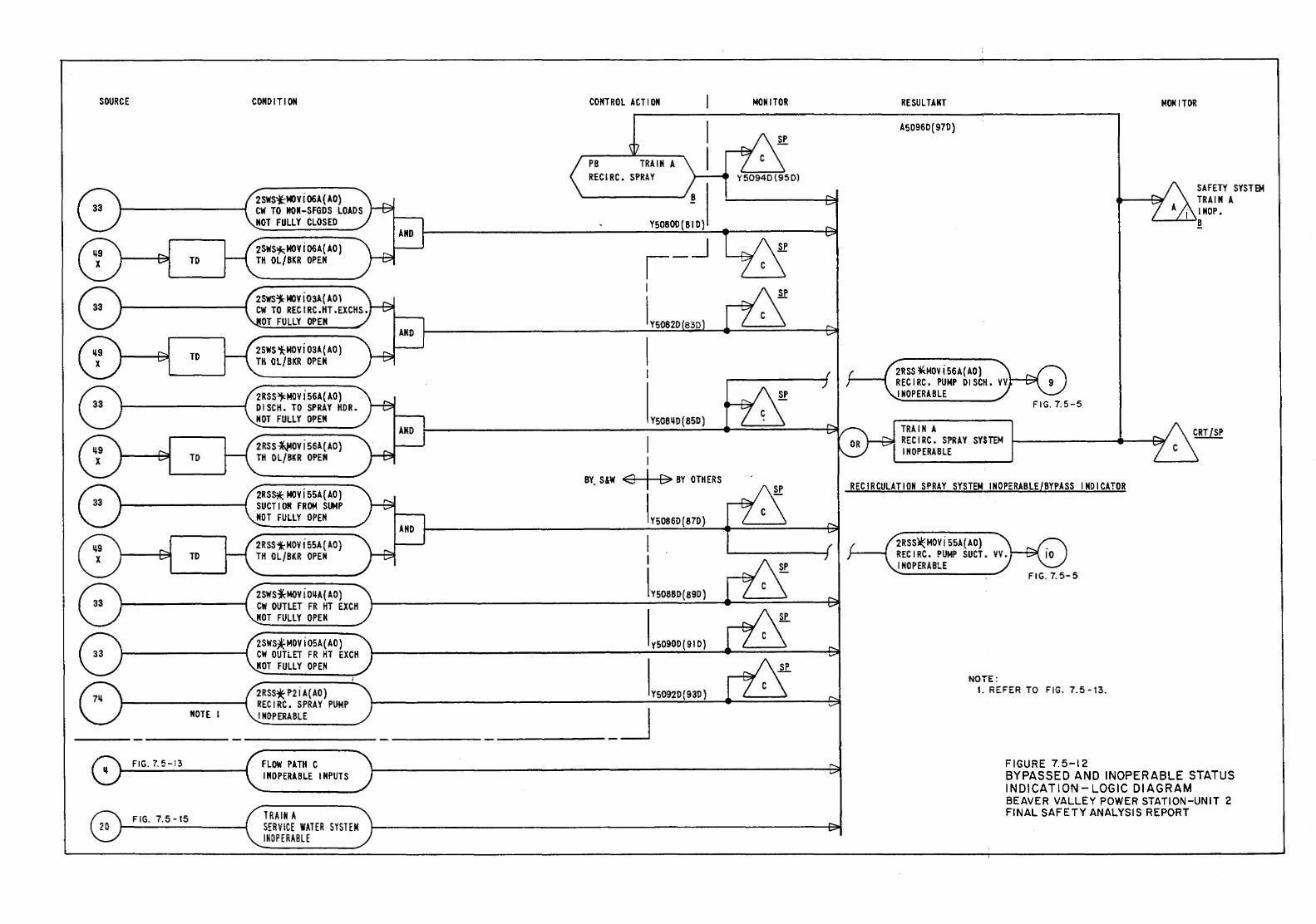
SOURCE
TO
TD
TO
TD
NOTE I
FIG. 7.5-13
FIG. 7.5-15
CONDIT I ON
2SWSitMOYi06A(AO) CW TO HON-SFGDS LOADS NOT FULLY CLOSED
2SWS~MOYi06A(AO) TH OL/BKR OPEN
2SWS~ MOY i 03A (AD\ CW TO RECIRC.HT.EXCHS.
OT FULLY OPEN
2SWS i;:MOYi 03A { AO) TH OL/BKR OPEN
2RSS~MOVi56A(AO) DISCH. TO SPRAY HDR. NOT FULLY OPEN
2RSS~OVi56A(AO) TH OL/BKR OPEN
2RS~ NOV i 55A ( AO) SUCTION FRON SUMP NOT FULLY OPEN
2RSSi;:MOV i 55A ( AO) TH OL/BKR OPEN
2SWS~MOViO~A{AO) CW OUTLET FR HT EXCH HOT FULLY OPEN
2SWS~MOViOSA(AO) CW OUTLET FR HT EXCH HOT FULLY OPEN
2RSS* P2 i A{ AO) RECIRC. SPRAY PUMP INOPERABLE
FLOW PATH C INOPERABLE INPUTS
TRAIN A SERVICE WATER SYSTEM ltWPERABLE
CONTROL ACT I ON NON I TOR
YS0800(BID)
l _ _j
Y50B~D{B5D)
BY, S&W <3 [> BY OTHERS SP
IY50B6D(B7D)
I I
L SOBBO ( B9D)
y5090D(91D)
Y5092D(93D)
___ _j
RESULTANT
A50960(97D)
2RSS ~MDV i 56 A{ AO) RECIRC. PUMP DISCH. VV INOPERABLE
TRAIN A RECIRC. SPRAY SYSTEM INOPERABLE
FIG. 7.5-5
RECIRCULATION SPRAY SYSTEM INOPERABLE/BYPASS INDICATOR
2RSS~MOVi55A(AO) RECIRC. PUMP SUCT. VV. I HOPERABLE
NOTE: I. REFER TO FIG. 7.5-13.
FIGURE 7.5-12
MONITOR
SAFETY SYSTEM TRAIN A INOP.
'-----'-....:....>~
BYPASSED AND INOPERABLE STATUS INDICATION-LOGIC DIAGRAM BEAVER VALLEY POWER STATION-UNIT 2 FINAL SAFETY ANALYSIS REPORT
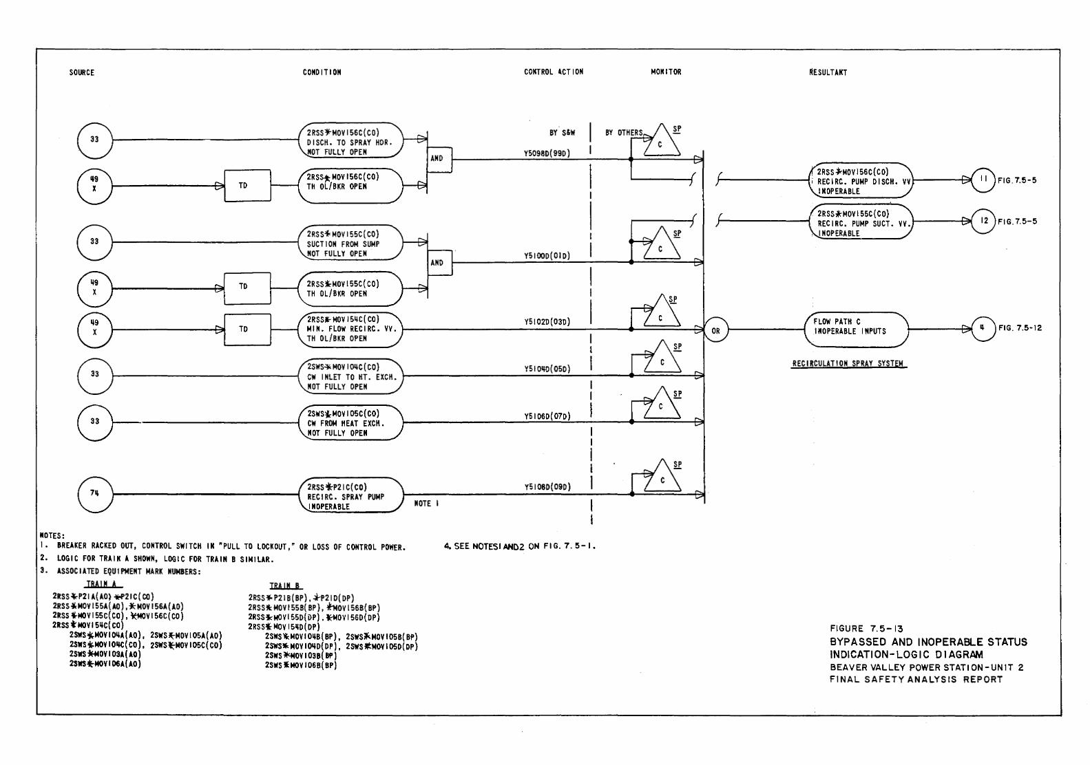
SOURCE
TO
TO
TO
0--
MOTES:
CONDIT! ON
2 RSS~MOV 156C (CO) DISCH. TO SPRAY HOR. NOT FULLY OPEN
2RSS .. MDV 156C (CO) TH OL/BKR OPEN
2RSS'f<MOV 155C( CO) SUCTION FROM SUMP NOT FULLY OPEN
2RSS *-to~OV 155C( CO) TH OL/BKR OPEN
2RSS. MDV IS~C( CO) MIN. FLOW RECIRC. VV. TH OL/BKR OPEN
2SWS~ lo!OV I OllC (CO) CW INLET TO HT. EXCK. NOT FULLY OPEN
2SWS~MOVI05C(CO) C\11 FROM HEAT EXCK. NOT FULLY OPEN
2RSS *P21 C( CO) RECIRC. SPRAY PUMP INOPERABLE NOTE I
1. BREAKER RACKED OUT, CONTROL SWITCH IN ~PULL TO LOCKOUT," OR LOSS OF CONTROL POWER. 2. LOGIC FOR TRAIN A SHOWN, LOGIC FOR TRAIN B SIMILAR. 3. ASSOCIATED EQUIPMENT MARK NUMBERS:
TRAil! A 2RSS ,..._P21 A(AO) +P21 C (CO} 2RSS olMOV 155A(AO), *MDV 156A(AO) 2RSS 4-MOV 155C( CO), ~V 156C( CO) 2RSS t MDV 151lC( CO)
2SWS~MOVIOilA(AO), 2SWS~MOYI05A{AO) 2SWS'i.MOV IOIK:( CO), 2SWS*:-MOV I OSC( CO) 2SWS~OYI03A(AO) 2SWS.;.MOY I 06A{AO)
TRAIN B 2RSS*- P21 B ( BP), ~P21 D( DP) 2RSS"-: MDV 155B( 8P), f-Mov 1568( BP) 2RSSfd.f()Vl55D{i>P), ~OVI560(DP) 2RSSl- MDV 15~0 ( OP)
2SWS '1<: MDV I OilS { BP) , 2SWSit(.MOV I 05 B( BP) 2sws-. MDV IOilD(DP), 2Sws.-:MOV I 05D(DP) 2SWS~OVI03B{BP) 2SWS I:MOV I 068( BP)
CONTROL 4CTION MOM IT OR
BY s&w
Y5098D(990)
YSIOOO(OID)
Y51020(03D)
Y5101Hl(05D)
Y51060(07D)
Y510B0(09D)
4. SEE NOTES! AND2 ON FIG. 7. 5-I.
RESULTANT
. 2RSS .}MQV 156C( CO) II FIG. 7.5-5 i RECIRC. PUMP DISCH. VV INOPERABLE
. 2RSS*MOV 155C (CO) RECIRC. PUMP SUCT. VV.
, I !!OPERABLE
FLOW PATH C INOPERABLE INPUTS FIG. 7.5-12
RECIRCULATION SPRAY SYSTEM
FIGURE 7.5-13 BYPASSED AND INOPERABLE STATUS INDICATION- LOGIC D I A GRAM BEAVER VALLEY POWER STATION-UNIT 2 FINAL SAFETY ANALYSIS REPORT
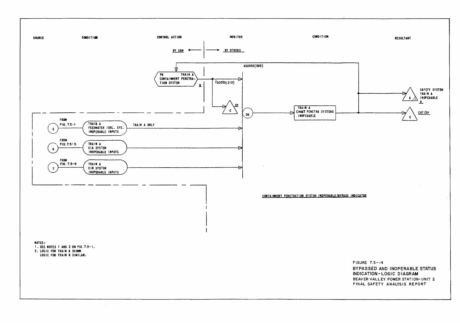
SOURCE
MOTES:
FROM FIG. 7.5-1
FROM FIG.7.5-3
FROM FIG. 7.5-4
TRAI" A TRAIN A ONLY
CONTROL ACTION MONITOR
BY OTHERS
PB TRAIN A COMTA I ICMEMT PEMETRA- >--~~----f~ TION SYSTEM
FEEOWATER I SOL SYS o 1----------------------.-...et INOPERABLE INPUTS
TRAIN A CIA SYSTEM IMOPERABLE INPUTS
TRAIN A CIB SYSTEM IMOPERABLE INPUTS
I o SEE MOTES I AND 2 ON- FIG. 7.5- I. 2. LOGIC FOR TRAIN i SHOWN
LOGIC FOR TRAIN B SIMILAR.
A5005D(06D)
COtiD IT ION RESULTAMT
SAFID SYSTEM ._---------rC,~ IRA IN A
J' ~ INOPERABLE ..L
TRAINA ~ CNWT PEMETRA SYSTEMS 1-------------- C ,CRT[SP
INOPERABLE
kONTAINMEMT P8NEIRAT!OM SYSTEM INOPERABLE/ByPAss INDICATOR
FIGURE 7.5-14 BYPASSED AND INOPERABLE STATUS INDICATION- LOGIC DIAGRAM BEAVER VALLEY POWER STATION-UNIT 2 FINAL SAFETY ANALYSIS REPORT
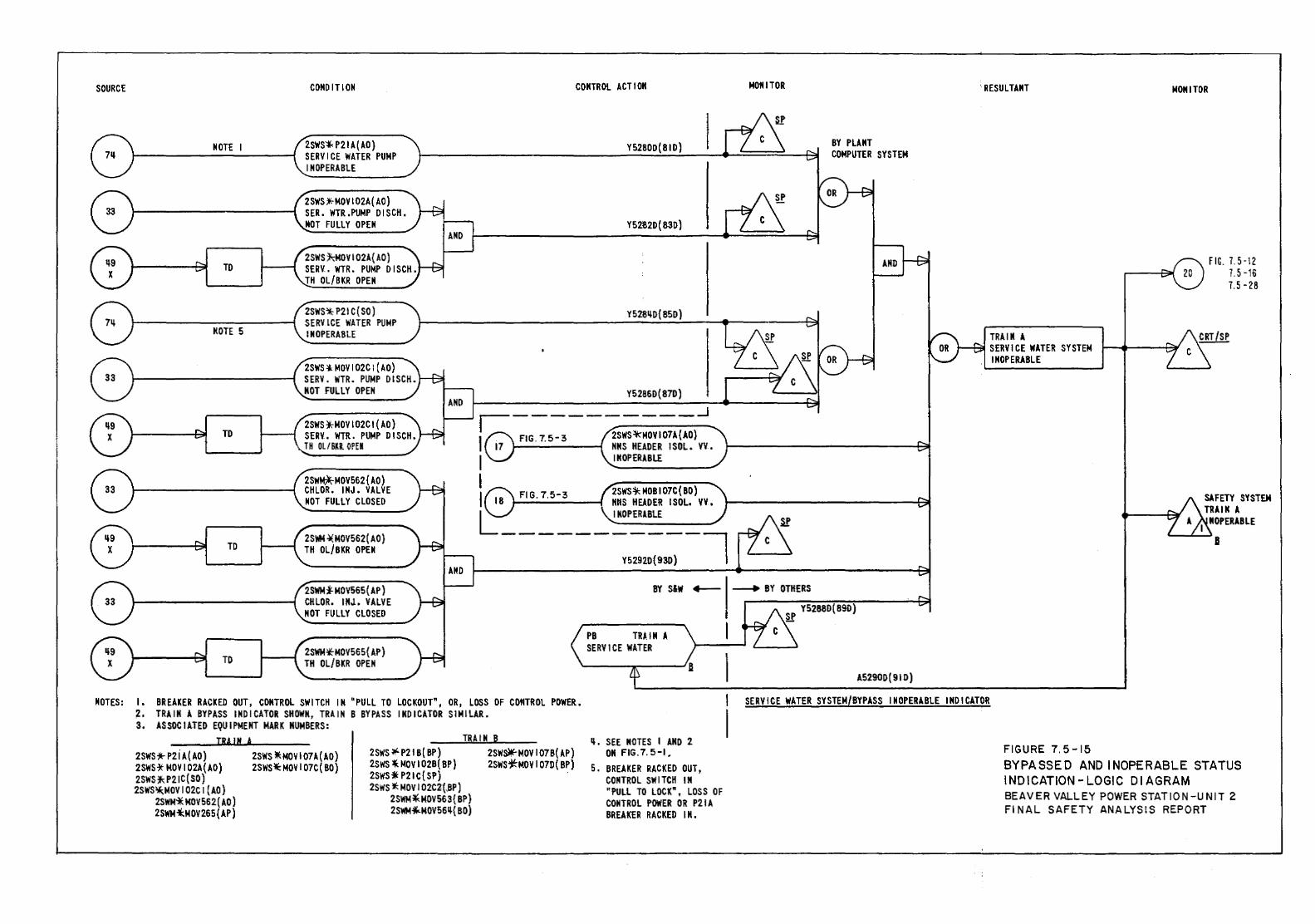
SOURCE
MOTE I
TO
MOTE 5
TO
TO
CONDITION
2SWS't< P21 A ( AO) SERVICE WATER PUMP INOPERABLE
2SWS ;1!;-MOV 102A( AO) SER. WTR.PUMP DISCH. MOT FULLY OPEN
2SWS~MOVI02A(AO) SER~. WTR. PUMP DISCH. TH OL/BKR OPEN
2SWS'* P21 C (SO) SERVICE WATER PUMP INOPERABLE
2SWS -1.: MDV I 02C 1 (AO) SERV. WTR. PUMP DISCH. MOT FULLY OPEN
2SWS)CMOVI02CI(AO) SERV. WTR. PUMP DISCH. TH OL/ BKR. OPE II
2SW~MOV562 ( AO) CHLOR. IMJ. VALVE MOT FULLY CLOSED
2S'IIM ~ MOVS62 (AD) TH OL/BKR OPEN
CONTROL ACTION
YS280D(81D)
Y5282D{83D)
Y528LlD( BSD)
Y5286D{87D) r--=-__________ _j
I FIG. 7.5-3 2SWS*MOVI07A(AO) 17 MMS HEADER I SOL. VV .•
1 ,IM_o_PE_RA_B_~------~
I FIG 2SWS*-MOB107C{BO) I . 7·5- 3 NitS HEADER ISOL. vv. I " ,l_NO_P_ER_A_BL_E ______ ~
L------~s:D(93~-l
MONITOR
BY PLANT COMPUTER SYSTEM
'RESULTANT
TRAIIt A SERVICE WATER SYSTEM INOPERABLE
MONITOR
FIG. 7.5-12 7.5-16 7.5-28
SAFETY SYSTEM TRAIN A
I ltOPERABLE '--......L..~B
2SWMi-MOV565{AP) CHLOR. INJ. VALVE NOT FULLY CLOSED
BY S&W 4--- --1> BY OTHERS
TO 2SWM-*"MOV565( AP) TH OL/BKR OPEN
MOTES: I • BREAKER RACKED OUT, CONTROL SWITCH I M "PULL TO LOCKOUT\ OR, LOSS OF CONTROL POWER. 2. TRAIN A BYPASS INDICATOR SHOWN, TRAIN B BYPASS INDICATOR SIMILAR. 3. ASSOCIATED EQUIPMENT MARK NUMBERS:
TRAIN A
2SWS* P2 i A(AO) 2SWS*MOVI02A(AO) 2SWSJ';: P21C (SO) 2SWS~MOV I 02C I (AD)
2SWM'* MDV 562 (AD) 2SWM~MOV265{AP)
2SWS W::MOV I 07A( AD) 2SWSlil:: MDV I 07C( 80)
TRAIN B 2SWS~P21 B( BP) 2SWS ~ MOV I 02B( BP) 2SWS* P21C{SP) 2SWS l!:. MDV I 02C2{,BP)
2SWM*MDV563{ BP) 2SWM ... MOV56Ll{ BO)
2SWs*- MDV I 07 B( AP) 2SWS;tMOVI07D(BP)
Ll. SEE NOTES I AND 2 ON FIG. 7. 5-I.
5. BREAKER RACKED OUT, CONTROL SWITCH IN "PULL TO LOCKft, LOSS OF CONTROL POWER OR P21A BREAKER RACKED IN.
A52900(910)
SERVICE WATER SYSTEM/BYPASS INOPERABLE INDICATOR
FIGURE 7. 5-15 BYPASSED AND INOPERABLE STATUS INDICATION-LOGIC DIAGRAM BEAVER VALLEY POWER STATION-UNIT 2 Fl NAL SAFETY ANALYSIS REPORT
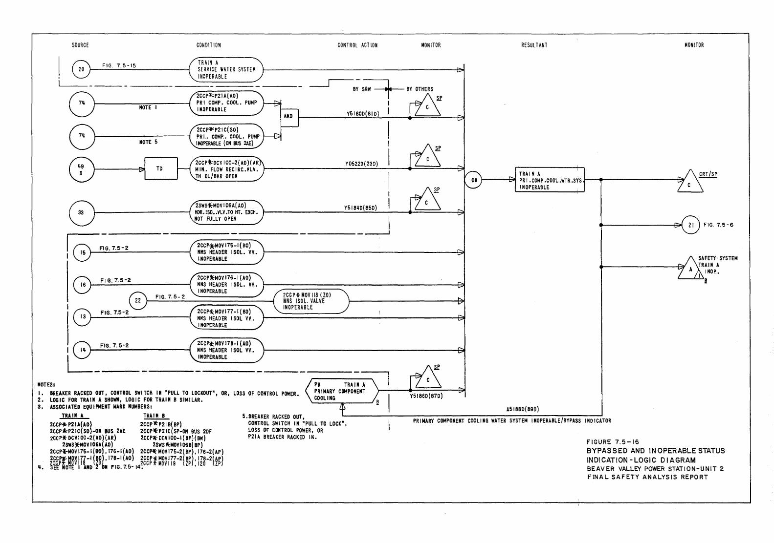
SOURCE
F!G. 7.5-15
CONDIT I ON
TRAIN A SERVICE WATER SYSTEM I NOPER ABLE
CONTROL ACT ION
- ___r---,-----~--~ -------- BY s&w t MOTE I
MOTE 5
TO
2CCP=I::;P21 A (AD) PRJ COMP. COOL. PUMP INOPERABLE
2CCPl""P21 C( SO) PR I.. COMP.. COOL. PUMP I MOPERABLE (ON BUS 2AE)
2CCP~OCVI00-2(AO)(AR MIK. FLOW RECIRC.VLV. TH OL/BKR OPEN
2SWS~MOVI06A(AO) 1-----------i HOR.ISOL.VLV .TO HT. EXCH.
Y5180D(810
Y05220(23D)
I
Y5181+D(85D) I MOT FULLY OPEN __ _j
FIG. 7.5-2
FIG. 7.5-2
I FIG. 7. 5-2
L::_ __ NOTES:
F!G. 7.5-2
2CCP~OVI75-I(BO} NMS HEADER ISOL. VV. INOPERABLE
2CCP~MOVI76-I(AO) NNS HEADER ISOL. VV. INOPERABLE
2CCP~MOV177-1 (BO) NNS HEADER ISOL VV. INOPERABLE
2CCP*MOV 178-1 (AD) NNS HEADER \SOL VV. INOPERABLE
2CCP f MDV I 18 ( ZO) NNS I SOL VALVE INOPERABLE
I. BREAKER RACKED OUT, CONTROL SWITCH IN ~PULL TO LOCKOUT", OR, LOSS OF CONTROL POWER. 2. LOGIC FOR TRAIN A SHOWN, LOGIC FOR TRAIN 8 SIMILAR. 3. ASSOCIATED EQUIPMENT MARK NUMBERS:
TRAIN A TRAIN B 5.BREAKER RACKED OUT, 2CCP._ P21 A(AO) 2CCP 1t"p21 8( BP) 2CCP~P21C(SO}-ON BUS 2AE 2CCP~P21C(SP-ON BUS 2DF 2CCP* DCV I 00-2{ AD) (AR) 2CCP~ DCV I 00-1 ( BP) { BW)
2SWS .. MDV I 06A (AD) 2SWS W:MOV I 068{ BP) 2CCP*-MOY 175-1 ( BO), 176-1 (AD) 2CC~ MOV 175-2( BP), 176-2{ AP) 2CCff~8V 177-1 ('8), 178-1 {AD) 2CCP.f MOVI77-2(BP), 178-2( AP1
~+. ~~~PioTE v 11 iNo ~~ bN FIG. r. s- 14~ccP * MDV 119 ( ZP I. 120 tZP l
CONTROL SWITCH IN nPULL TO LOCK", LOSS OF CONTROL POWER, OR P21A BREAKER RACKED IN.
MONITOR RESULTANT MON! TOR
TRAIN A '-"--~ PR I . COMP .COOL .WTR .SYS }----1~---------t~
INOPERABLE
AS\ 880( 890)
FIG. 7.5-6
SAFETY· SYSTEM TRAIN A
INOP.. '-----'~.B
PRIMARY COMPONENT COOLING WATER SYSTEM INOPERABLE/BYPASS INDICATOR
FIGURE 7.5-16 BYPASSED AND INOPERABLE STATUS INDICATION -LOGIC D \A GRAM BEAVER VALLEY POWER STATION-UNIT 2 FINAL SAFETY ANALYSIS REPORT
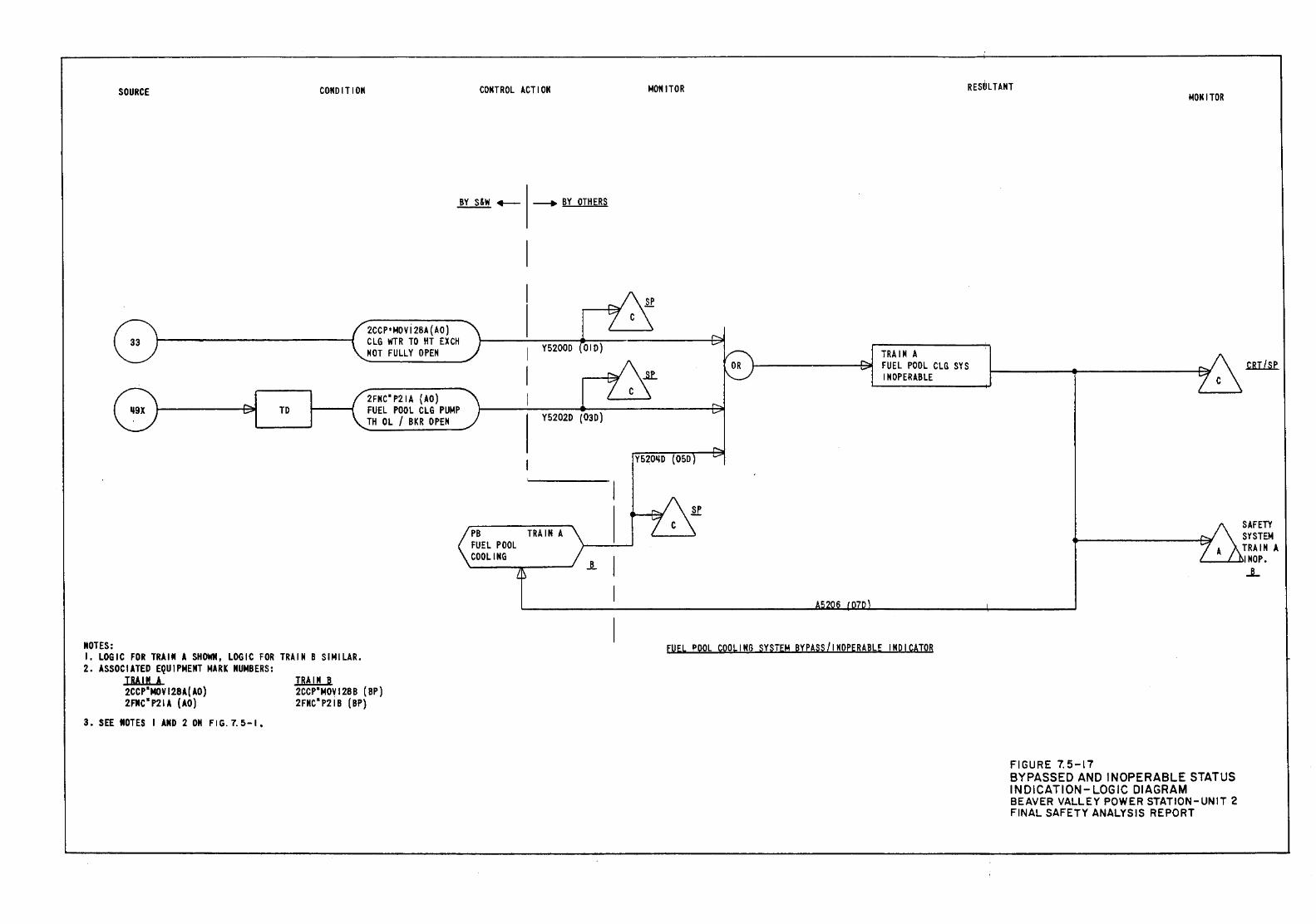
SOURCE CONDITION
TO
MOTES:
CONTROL ACTION
BY S&W .,.___ ~BY OTHERS
2CCP•~OVi2BA(AO) CLG WTR TO HT EXCH NOT FULLY OPEN
2FNC*P21A (AO) FUEL POOL CLG PU~P TH OL / BKR OPEN
Y52000 OlD)
Y5202D (030)
TRAIN A
..1.
I, LOGIC FOR TRAIN A SHOWN, LOGIC FOR TRAIN B SIMILAR. 2. ASSOCIATED EQUIPMENT MARK NUMBERS:
TRAIN A 2CCP*MOYl28A(AO) 2FIIC* P2l A (AO)
3. SEE MOTES I AND 2 OM FIG. 7.5-1.
TRAIN 8 2CCP*MOY128B (BP) 2FNC*P21B (BP)
~OM ITOR RESULTANT
Y5201tD (050
TRAIN A FUEL POOL CLG SYS INOPERABLE
FUEL POOL COOLING SYSTEM BYPASS/INOPERABLE INDICATOR
MONITOR
SAFffi SYSTEM TRAIN A
'---~I HOP •
FIGURE 7.5-17 BYPASSED AND INOPERABLE STATUS INDICATION-LOGIC DIAGRAM BEAVER VALLEY POWER STATION-UNIT 2 FINAL SAFETY ANALYSIS REPORT
..1..
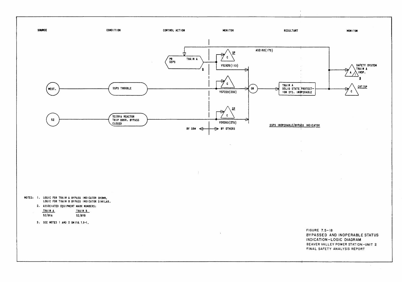
NOTES:
SOURCE CONDITION
1.
2.
3.
LOGIC FOR TRAIN A BYPASS INDICATOR SHOWN, LOGIC FOR TRAIN B BYPASS INDICATOR SIMILAR. ASSOCIATED EQUIPMENT MARK NUMBERS: TRAIN A TRAIN B 52/BYA 52/BYB
SEE NOTES 1 AND 2 ON fiC. 7.5-1.
SSPS TROUBLE
52/BYA REACTOR TRIP BRKR. BYPASS CLOSED
CONTROL ACT I OM MONITOR
Y52IOD(11D)
+ Y00260(27D)
BY S&W BY DlliERS
RESULTANT MOM I TOR
A5216D(17D)
TRAIN A SOLID STATE :PROTECT- 1--~111------i:::;l; ION SYS. INOPERABLE
SSPS INOPERABLE/BYPASS INDICATOR
FIGURE 7.5-18 BYPASSED AND INOPERABLE STATUS INDICATION -LOGIC DIAGRAM BEAVER VALLEY POWER STATION -UNIT 2 FINAL SAFETY ANALYSIS REPORT
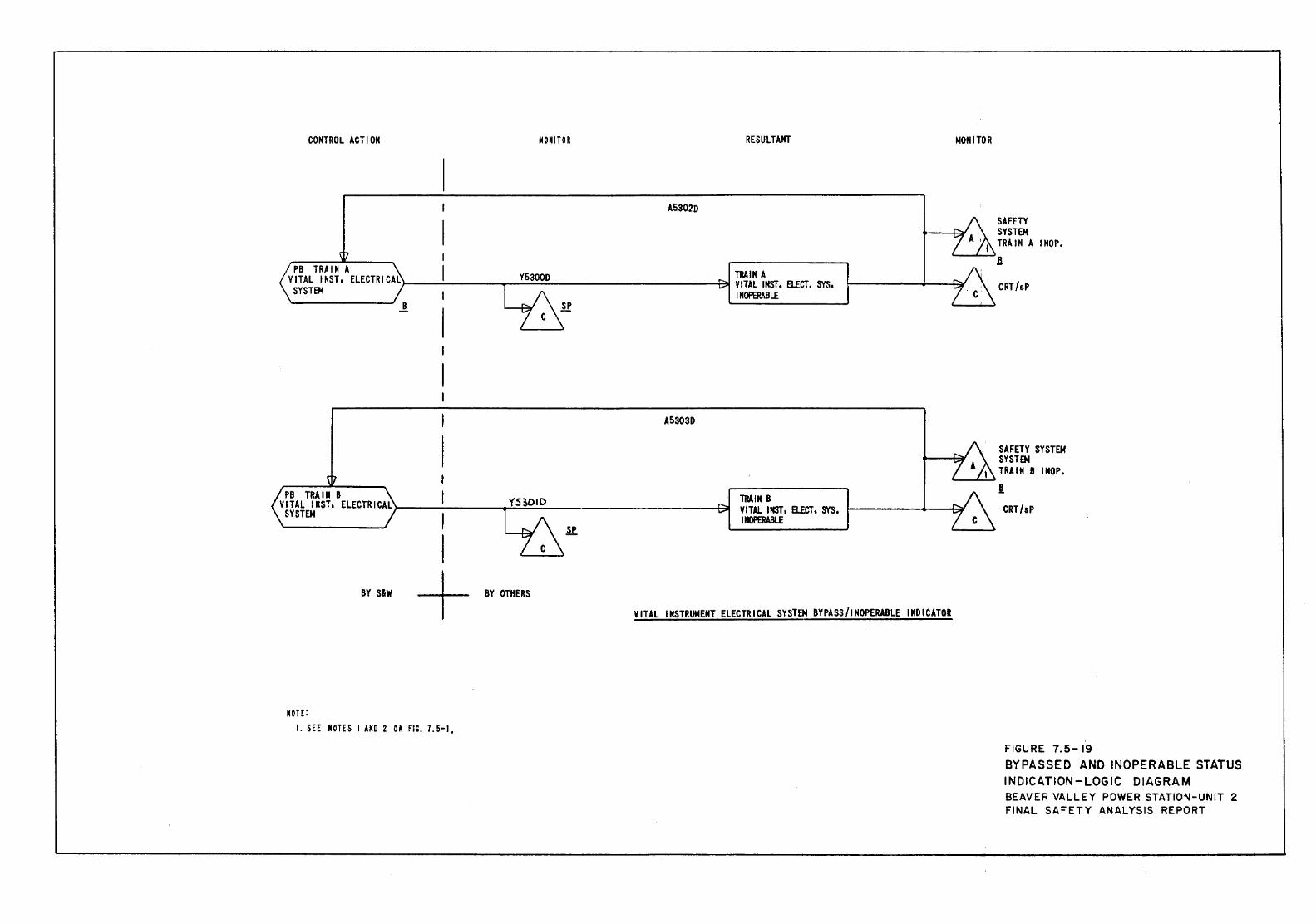
CONTROL ACTION liON I TOR RESULTANT
A5302D
,___ _____ ___; B
A5303D
I PB TRAIN B I
VITAL I NST, ElECTR ICAL>-------....,..:-=..::=;...._------------l:~ SYSTEM I
TRAIN B VITAl IMST, ELECT, SYS, llllPERABL.E
I ----t----- BY OTHERS BY S&W
VITAL INSTRUMENT ELECTRICAL SYSTEM BYPASS/INOPERABLE INDICATOR
Morr: I. SEE MOTES I AKD 2 0 M m. 7. 5-I,
MONITOR
'--.....~.....,;~
SAFETY SYSTEM TRll N A I NOP •
.B
CRT/sP
SAFETY SYSTEM SYSTEM TRAIN 8 INOP.
l -CRT /sP
FIGURE 7.5-19 BYPASSED AND INOPERABLE STATUS INDICATION-LOGIC DIAGRAM BEAVER VALLEY POWER STATION-UNIT 2 FINAL SAFETY ANALYSIS REPORT
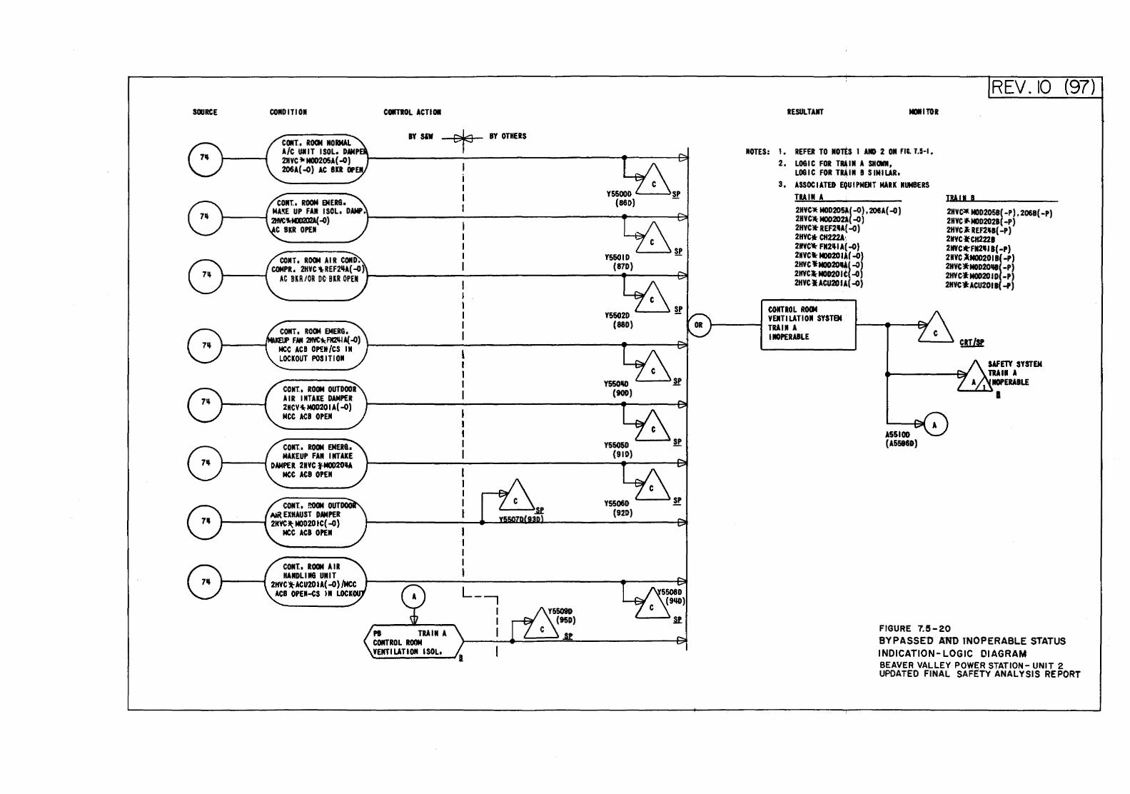
SCRJRCE CONDITIOII
CONT. I ROCI4 NORMAL A/C UIIIT ISOL, DAMP 2HYC 't<MOD205A( -0) 206A(-O) AC BIR OPEN
CONT. ROOM EMERG,
COIITIOL ACTION
BY SloW BY OTHERS
FNt 211VC~ fii:NI A(..()) NCC ACB OPEN/CS IN 1---------------------..----~ LOCKOUT POSITION
CONT., ROOM OUTDOOR AIR INTAKE DAMPER 2HCY~ MOD20 I A( -0) MCC ACB OPEN
CQIIT., ROOM EMERQ, MAKEUP FAN INTAKE
DAMPER 2HYC fM002011A MCC ACB OPEN
COIIT. I !lOOM OUT AIR EXHAUST DAMPER
1-----1 2HYC !1;: MOD20 IC( ..(1} MCC ACB OPEN
COIIT. I ROOM AIR HANDLIIIQ UNIT
2HYC1rACU201A(-O)/MCC ACB OPEII.CS IN LOCK
N Will A CONTROL ROOM VENTILATION ISOL,
YSSOIH) (900)
YSSOID (920)
RESULTANT MDIII TOR
NOTES: 1. REFER TO MOrtS I AND 2 ON fiC. 1.5-1. 2. LOGIC FOR TR4IN A SHOWN,
LOGIC FOR T~IN B SIMILAR. 3. ASSOC I ATED EQU I PMEIIT MARK NUMBERS
TRAIN A 2HYC* MOD205A( -0) , 206A( ..(1) 2HYC. M00202l( ..0) 2HYC)t REF2111A( -0) 2HYC* CH222A·, 2HYC_. FN2~1A(-O) 2HYC* MOD20 14( -0) 2HYC .. M0020if4( -0) 2HYC:tM00201C( ..0) 2HVC I ACU20 I A( -0)
COIITROL 10114 VENTI LAT I ON SYSTEM
t------1 TRAIN A INOPERABU
ASSIOD (AS!i86D)
REV. 10 (97)
TRAil B
2HYC:llt MOD2058( -P) , 2068( -P) 2HYC '*'MOD202B( -P) 2HYClt REF2111B( -P) 2HYC.CH2221 2HYC!l-FII21111 B( -P) 2HVC l-M00201 B( ..P) 2HYC.-MOD20111( -P) 2HYCJ: MOD20 I D( -P) 2HVC~ACU201B(..P)
SAFm SYSTEM TRAil A
NOPERABLE "--........,~I
FIGURE 7.5-20 BYPASSED AND TNOPERABLE STATUS INDICATION- LOGIC 01 AG RAM BEAVER VALLEY POWER STATION- UNIT 2 UPDATED FINAL SAFETY ANALYSIS REPORT
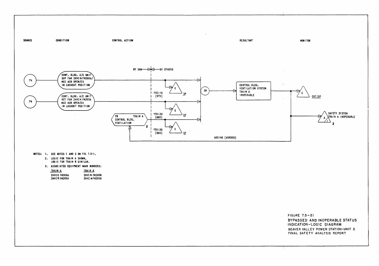
SOURCE CONDITION CONTROL ACTION
BY S&W c:fa BY OTHERS CONT. BLDG, A/C UNIT SUP FAN 2HVC"'-FN266A/ MCC ACB OPEN/CS ~------------+---...... -------+-?! IN LOCKOUT POSITION
NOTES: I. SEE NOTES 1 AND 2 ON m. 1.5-1. 2. LOGIC FOR TRAIN A SHOWN,
LOGIC FOR TRAIN B SIMILAR. 3. ASSOCIATED EQUIPMENT MARK NUMBERS:
TRAIN A 2HVC1: FN266A 2HVC*. FN265A
TRAIN B 2HVC~ FN266B 2HVC ~FN265B
PB TRAIN A CONTROL BLDG,
Y5511D (970)
VENT I LA Tl ON "--------' ~ I
I Y5513D I (990) I A5511lD (A5600D)
RESULTANT
CONTROL BLDG, VENTILATION SYSTEM TRAIN A INOPERABLE
MONITOR
FIGURE 7.5-21 BYPASSED AND INOPERABLE STATUS INDICATION-LOGIC DIAGRAM BEAVER VALLEY POWER STATION-UNIT 2 FINAL SAFETY ANALYSIS REPORT
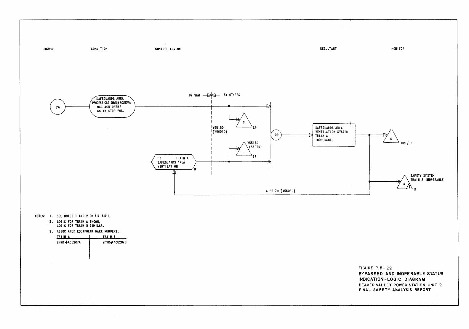
SOURCE CONDITION
SAFEGUARDS AREA PROCfSS CL.G 21f1RtACU207A
!-------1 MCC ACB OPEN/ CS IN STOP POS.
NOTES: I. SEE NOTES I AND 2 OM m. 7.5·1, 2. LOGIC FOR TRAIN A SHOWM,
LOGIC FOR TRAIN 8 SIMILAR. 3. ASSOCIATED EQUIPMENT MARK NUMBERS:
TR IN TRAIN 8 2HVR .fACU207A 2HVR,f.ACU207B
CONTROL ACTION
PB TRAIN A SAFEGUARDS AREA VENTILATION
BY S&W Df:o BY OTHERS
I I l IY5515D I(Y5601D) I l I I I I
RESULTANT
SAFEGUARDS AREA VENTILATION SYSTEM
1-------+31 TRAIN A INOPERABLE
A 5517D (A5603D)
MONITOR
FIGURE 7.5-22
SAFETY SYSTEM TRAIN A INOPERABLE
BYPASSED AND INOPERABLE STATUS INDICATION-LOGIC DIAGRAM BEAVER VALLEY POWER STATION-UNIT 2 FINAL SAFETY ANALYSIS REPORT
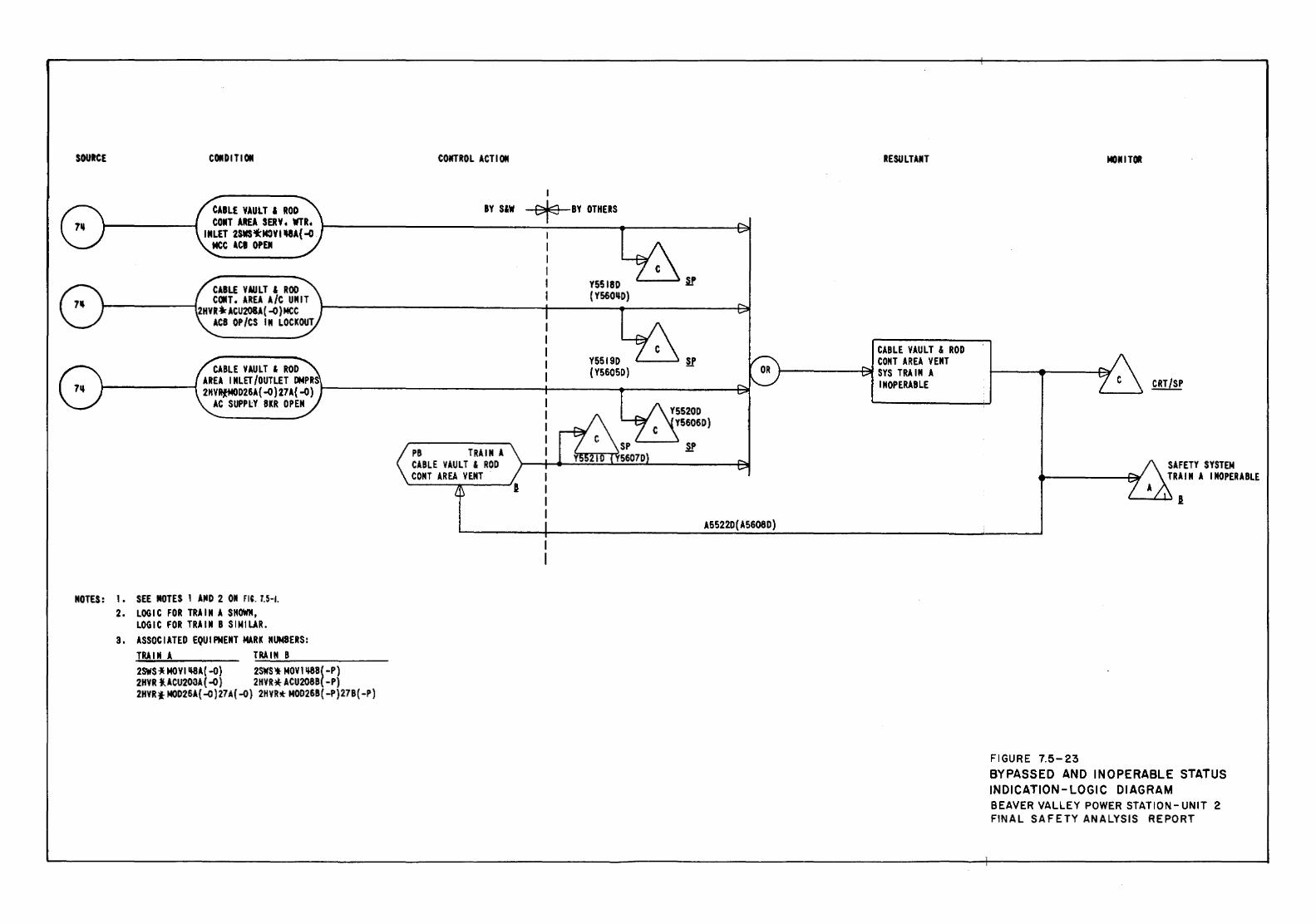
SOUIC£ COlt D ITI Olt CONTROl ACTIOM
Y5519D ""'"----' M' (Y5605D) CABLE VAULT & ROD
AREA INLET/OUTLET DMPR 1-------t 2HVRti«<D26A{ -Q)27A( -Q) t---------------+-----...-------~
AC SUPPlY BKR OPEN
MOTES: 1 • SEE MOTES 1 AND 2 Olt fiC. 7.5-1. 2. LOGIC FOR TRAIN A SHOWN,
LOGIC FOR TRAIN 8 SIMILAR. 3. ASSOCIATED EQUIPMENT MARK NUMBERS:
TRA I M A T:..:.:RA:.:..I:..:.:M~B;.._ _____ _ 2SWU~ MDVI ~A{ -o) 2SWS\l MOVl ~8( -P) 2HVR l{.ACU203A( -o) 2HYR* ACU208B( -P) 2HVRt M0026A( -o) 27A( -o) 2HYR* MOD26B( -P)27B( -P)
PB TRAIN A CABLE VAULT & ROD COMT AREA VENT
A5522D(A5608D)
RESULTAMT
CABLE VAULT & ROD COMT AREA VENT
1-------AI SYS TRAIN A INOPERABLE
MONITOR
FIGURE 7.5-23
SAFETY SYSTEM TRAIN A INOPERABLE
BYPASSED AND INOPERABLE STATUS INDICATION-LOGIC DIAGRAM BEAVER VALLEY POWER STATION-UNIT 2 FINAL SAFETY ANALYSIS REPORT
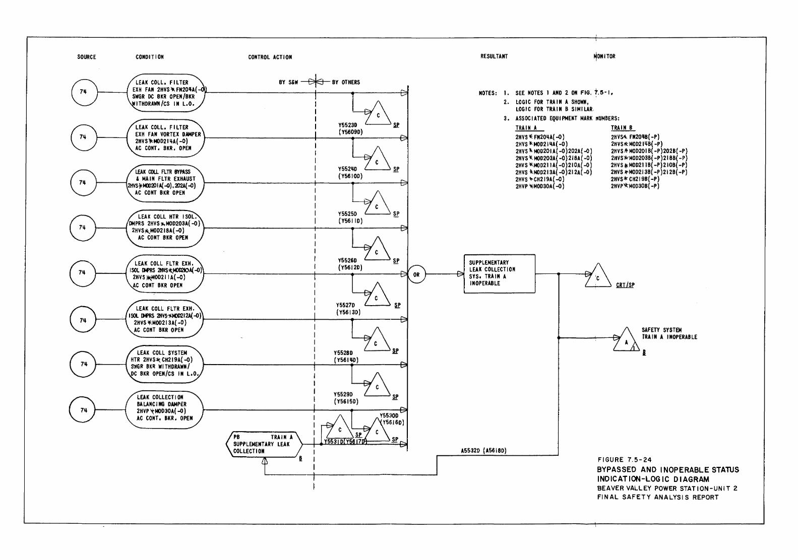
SOURCE CONDITION CONTROL ACTION
LEAK COLL 1 F I L TER BY S&W cts BY OTHERS EXH FAN 2HVS~FN20~A( -)1-------------+----..-------t=::f SWGR DC BKR OPEN/BKR
ITHDRAWH /CS IN L. 0,
LEAK COLL 1 F I L TEll Y5523D '-----' Sf EXH FAN VORTEX DAMPER t--------------i---(_Y_56..,.0~-"9D_J ____ t?t 2HVS~MOD21 ~A( -0) AC CONT. BKR. OPEN
Y552~D '----~ SP (Y5610D)
Y55250 SP (Y56J ID)
Y5526D ~ (Y5612D)
Y5527D ~ (Y5613D) LEAK COLL FLTR EXH.
...,___--'-' I SOL IM'RS 2HV8-':!\MJD212A( ~) 2HVS~J400213A( -0) t------------__,1-------4~---·-+31
AC CONT BKR OPEN
LEAK COLL SYSTEM HTR 2HVS~ CH219A( -0) .,___---t ~GR BKII WITHDRAWN/ DC BKR OPEN/CS IN L10.
LEAK COLLECT I ON BA LANC I NG DAMPER 2HVP 'tMOD30A( -0) AC CONT. BKR. OPEN
PB TRAIN A SUPPLEMENTARY LEAK COLLECTION
Y5528D {Y561~)
Y5529D (Y56150)
if
RESULTANT ~ON I TOR
NOTES: I. SEE NOTES I AND 2 ON FIG. 7.5·1, 2. LOGIC FOR TRAIN A SHOWN,
LOGIC FOR TRAIN B SIMILAR, 3. ASSOCIATED EQUIPMENT MARK ~UMBERS:
SU PPLEMEMTARY LEAK COLLECT I ON SYS1 TRAIN A INOPERABLE
A5532D {A5618D)
TRAIN A 2HVS '( FN20~A( -0) 2HVS l< MOD21 ~A ( -0) 2HVS tF. MOD201 A{ -0 )202A{ -0) 2HVS ~ MOD203A( -0) 218A ( -0) 2HVS *-MOD211A( -0)210A( -0) 2HVS lNOD213A( -0) 212A( -0) 2HVS •CH2 I 9A( -0) 2HVP ~MOD30A ( -0)
TRAIN B 2HYS4. FN20~( -P) 2HVSJt;:MOD21 ~B( -P) 2HVS It- MOD201 B( -P)202B( -P) 2HVS~MOD203B(-P)218B(-P} 2HVS ~ MOD211 B( -P) 210B( -P) 2HVS "'MOD213B( -P )212B( -P) 2HVS*' CH219B( -P) 2HVP'.tMOD30B( -P)
CRT/SP
SAFETY SYSTEM TRAIN A INOPERABLE
B.
FIGURE 7.5-24
BYPASSED AND INOPERABLE STATIJS INDICATION-LOGIC DIAGRAM BEAVER VALLEY POWER STATION-UNIT 2 Fl N AL SAFETY ANALYStS REPORT
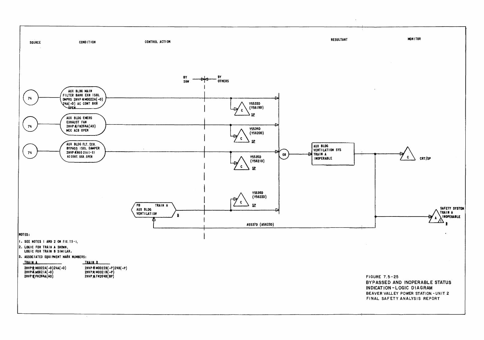
SOURCE
NOTES:
CONDITION
AUX BLDG EMERG EXHAUST FAN 2HVP~FH26~A(AO) MCC ACB OPEN
AUX BLDG fLT. EIH. BYPASS ISOL DAMPER 2HVP*Moil 2U (-OJ AC COIIT. BKR. 0 PEN
I • SEE NOTES I AND 2 ON FIG. 1.5 -1.
2. LOGIC FOR TRAIN A SHOWN, LOGIC FOR TRAIN B SIMILAR.
3. ASSOCIATED EQUIPMENT MARK NUMBERS: IRA IN A TRAI N B 2HVPt NOD22A{ ~) 2~A( ~) 2HVP * MOD2 2B( -P) 2 ~B( -P) 2HYP-.1: M0021A( -o) 2HVP*NOD21 B( -P) 2HYP{ FN26~A(AO) 2HYP * FN26~B( BP)
CONTROL ACTION
BY S&W
~ BY --i'f"~..,_- OTHERS
Y5533D (Y5619D)
'-----~~
Y553~D (Y5620D)
"---_. H
Y5535D (Y5621D)
~
Y5536D (Y5622D)
u
A5537D {A5623D)
RESULTANT
AUX BLDG VENTILATION SYS
'------911 TRAIN A INOPERABLE
MONITOR
CRT/SP
FIGURE 7.5-25
SAFETY SYSTBt TRAIN A
IIOPERAILE I I
BYPASSED AND INOPERABLE STATUS INDICATION -LOGIC DIAGRAM BEAVER VALLEY POWER STATION -UNIT 2 FINAL SAFETY ANALYSIS REPORT
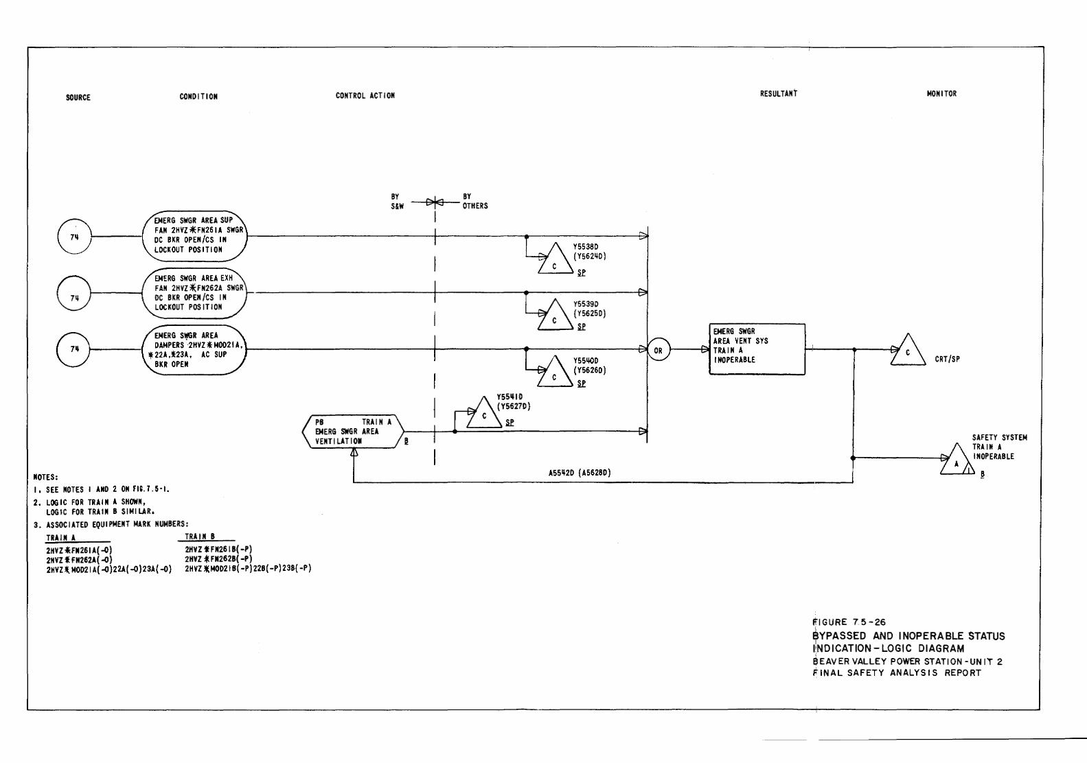
SOURCE CONDITION CONTROL ACTION
BY S&W
~ BY -+lL>J<l!IW=+- OTHERS I ENERG SWGR AREA SUP
FAN 2HVZ~FN261A SWGR DC BKR OPEN/CS IN r---------------------------~------------~r---------------~~ LOCKOUT POSITION
EMERG SWGR AREA EXH FAN 2HVZ*FN262A SWGR DC BKR OPEN/CS IN LOCKOUT POSITION
ENERG S,.SR AREA
Y5538D (Y5621W)
L--..lSf
Y55390 {Y5625D)
'---~Sf
DAMPERS 2HYZ * M0021 A, t----------------------------1----------~--------------~ • 22A ,l23A, AC SUP BKR OPEN
NOTES: I, SEE NOTES I AND 2 ON m. 1. 5·1. 2. LOGIC FOR TRAIN A SHOWN,
LOGIC FOR TRAIN B SIMILAR, 3. ASSOCIATED EQUIPMENT MARK NUMBERS:
TRAIN A 2HYZ *FN261 A( -0) 2HVZtFN262A( -o) 2HVU. MOD21 A( -o )22A( -0 )23A( -0)
TRAIN B 2HVZ fFN261B( -P) 2HVZ *FN262B( -P) 2HVZ tMOD21 B{ -P) 22B( -P) 23B{ -P)
PB TRAIN A EMERG SWGR AREA VENTILATION
Y55~1D
(Y5627D}
~
Y55LIOD {Y56260)
~___~u
A55~2D {A5628D)
RESULTANT
EMERG SWGR AREA VENT SYS ..,___-F;ai TRA I N A INOPERABLE
MONITOR
CRT/SP
SAFETY SYSTEM TRAIN A INOPERABLE
'---.L.U ~
itiGURE 75-26 i ~YPASSED AND INOPERABLE STATUS I:NDICATION- LOGIC DIAGRAM E!IEAVER VALLEY POWER STATION -UN IT 2 FINAL SAFETY ANALYSIS REPORT
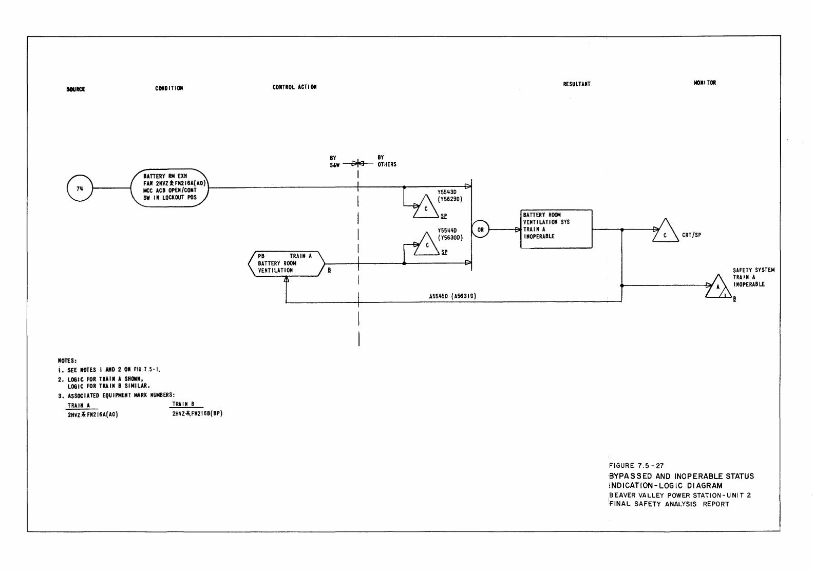
SOUilCE CONDITION COilTROl ACT! ON
BY BY S&W DfEJ OTHERS
BAITERY RN EXH I FAll 2HVZ~FII216A(AO) MCC ACB OPEII/COIIT t----------------f-----+------~ SW Ill lOCKOUT POS Y55~30
NOTES: i. SEE NOTES I AND 2 011 m. 7 .5-I. 2. LOGIC FOR TRAIN A SHOWN,
LOGIC FOR TRAIN B SIMILAR. 3. ASSOCIATED EQUIPMENT MARK NUMBERS:
TRAIN A 2HVZ * FM216A( AO)
TRAIN B 2HVZ-.1I,FM216B{BP)
PB TRAIN A BATTERY ROOM VENT llA Tl ON
{Y5629D)
Y55~~D
{Y5630D)
t---..)~
A55~5D {A5631D)
RESUll.liiT
BAITERY ROOM VENTI UTI OM SYS
J...-----1~ TRA I M A INOPERABLE
140111 TOI
CRT/SP
FIGURE 7.5-27
SAFETY SYSTEM TRAIN A INOPERABLE
BYPASSED AND INOPERABLE STATUS INDICATION-LOGIC DIAGRAM .BEAVER VALLEY POWER STAT I ON-UNIT 2 'FINAL SAFETY ANALYSIS REPORT
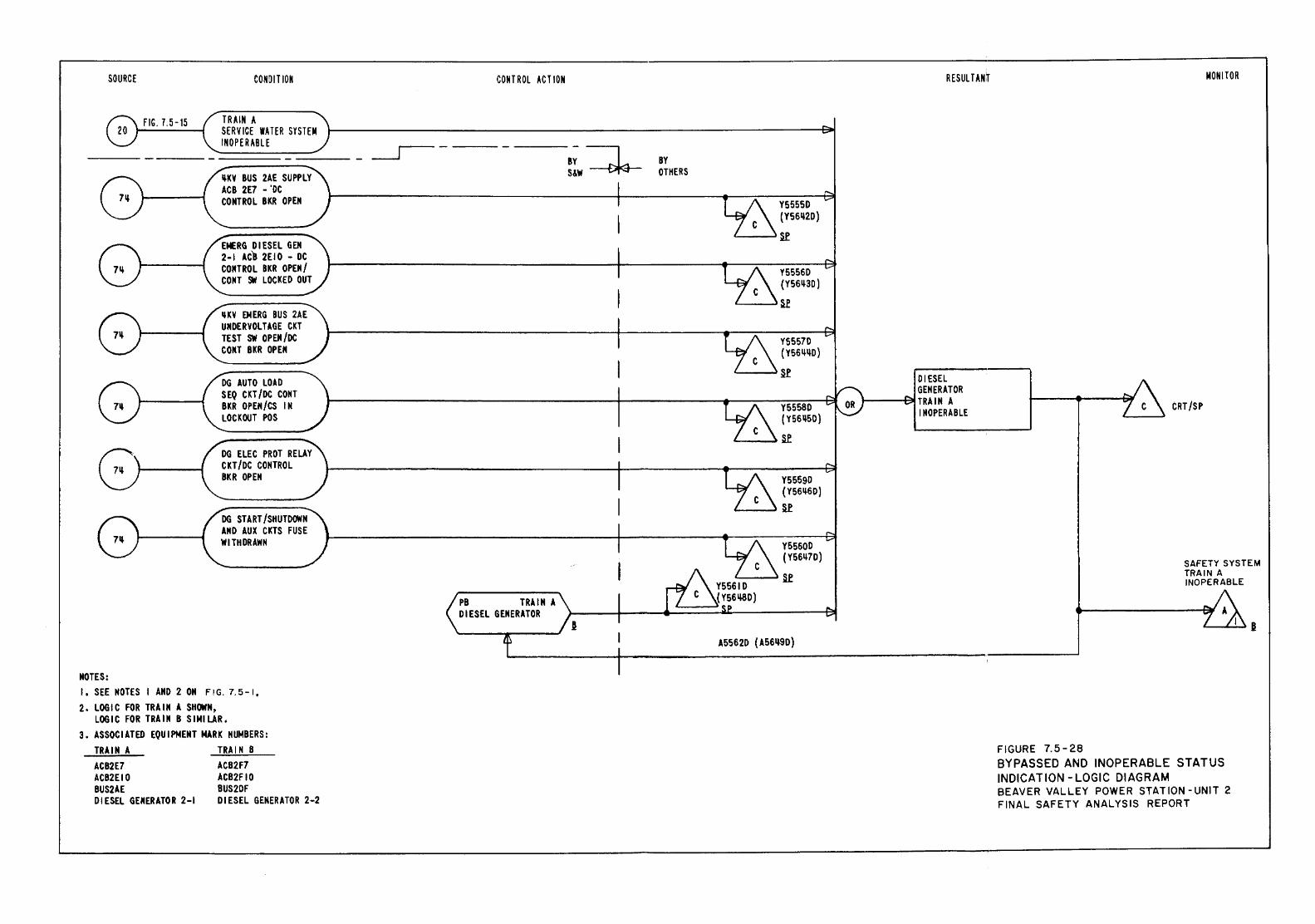
SOURCE
FIG. 7.5-15
NOTES:
CONDIT ION
TRAIN A SERVICE WATER SYSTEM
:""::::INO=P=ER=A=Bl=E =-:::-=:::::...__ _ _r- _ ~KV BUS 2AE SUPPLY ACB 2E7 -'DC CONTROL BKR OPEN
EMERG DIESEL GEM 2-1 ACB 2EIO - DC CONTROL BKR OPEN/ CONT SW LOCKED OUT
qKV EMERG BUS 2AE UNDERYOLTAGE CKT TEST SW OPEN /DC CONT BKR OPEN
DG AUTO LOAD SEQ CKT /DC CONT BKR OPEM/CS IN LOCKOUT POS
DG ELEC PROT RELAY CKT /DC CONTROL BKR OPEN
DG START/SHUTDOWN AND AUX CKTS FUSE WITHDRAWN
I, SEE NOTES I AND 2 ON FIG. 7.5-1,
2. LOGIC FOR TRAIN A SHOWN, LOGIC FOR TRAIN B SIMILAR.
3. ASSOCIATED EQUIPMENT MARK NUMBERS: TRAIN A ACB2E7 ACB2EIO BUS2AE DIESEL GENERATOR 2-1
TRAIN 8 ACB2F7 ACB2FIO BUS2DF DIESEL GENERATOR 2-2
CONTROl ACT ION
-~ BY S&W
BY OTHERS
Y5555D (Y561l2D)
<---J~
Y5556D (Y561l3D)
L---l~
Y5557D ( Y561lllD)
'---....:I .Sf
Y5558D (vssqso)
L....--~ Sf
Y5559D (Y561l6D)
'---....:1 u
Y5560D (Y561l7D)
L--~ Sf
A5562D (A56q9D)
RESULTANJ
DIESEL GENERATOR
1-----t~ TRAIN A INOPERABLE
FIGURE 7.5-28
MONITOR
CRT /SP
SAFETY SYSTEM TRAIN A INOPERABLE
BYPASSED AND INOPERABLE STATUS INDICATION -LOGIC DIAGRAM BEAVER VALLEY POWER STATION -UNIT 2 FINAL SAFETY ANALYSIS REPORT
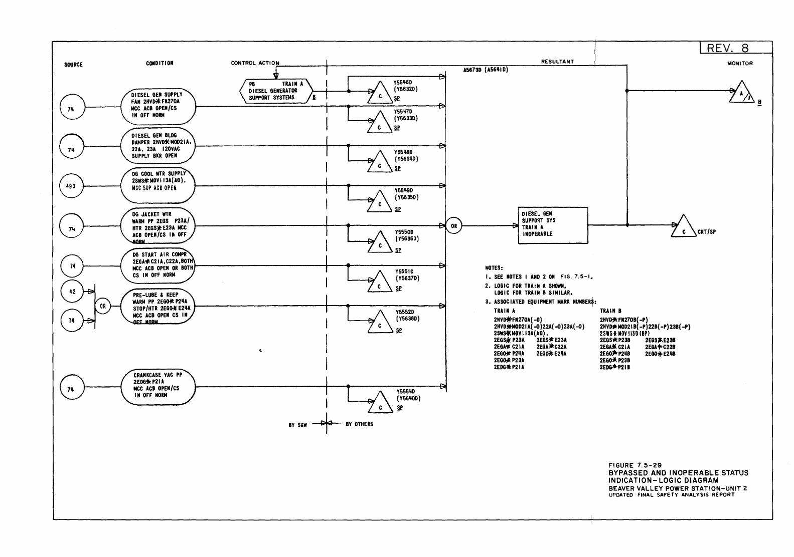
SOURCE COIID Ill OJI
DIESEl GEJI SUPPlY FAN 2HV~FM270l MCC ACB OPEN/CS IN OFF NORM
DIESEL GEM BLDG
PI TRAIN A Dl ESEL GENERATOR SUPPORT SYSTEMS
~-->
Y551J6D (Y5632D)
R Y55~7D
(Y5633D)
Sl
D~PER2HV~Mmn1A, ~---------------------------+----.-------------------~ 22l, 23l 120VAC SUPPlY BKR OPEN
DG COOL WTR SUPPLY 2SW~MOVI13l(l0), MCC SUP ACB OP Elt
DG JACKET WTR WARM pP 2EGS P23A/ HTR 2EG~E23A MCC ACB OPEN/CS IJI Off
DG START AIR COMPR
Y55~D {Y5631W)
L.---....)R
Y55~D (Y5635D)
.....__ .... Sl
Y5550D (Y5636D)
'--~Sl
2EGA.C21 A, C22A,IOT 1------------------------+-------------------....at MCC ACB OPEN OR BOTH CS IN OFF IIORM
CRANKCASE YAC PP 2EDG'IIcP21A MCC ACB OPEN/CS IN OFF NORM
I
Y5551D (Y5637D)
..___ .... R
Y5552D (Y5638D)
~-_.R
Y555140 { Y56110D)
R '---~
BY SlW + BY OTHERS
RESULTANT A5673D (A56'1 D)
DIESEl GEM SUPPORT SYS
J---------~;~ TRAIN A IIIOPERABLE
NOTES: I. SEE JIOTES I AND 2 011 FIG. 7.5-1. 2. LOGIC FOR TRAIN A SHOWN,
LOGIC FOR TRAIN B SIMILAR. 3, ASSOCIATED EQUIPMENT MARK NUMBERS:
I TRAIJI A TRAIN B 2HV~FJI270A(-D) 2HV~FN270B(-P) 2HVD~MOD21A(-0)22A(-0}23l(-O) 2HVDJtMOD21B(-P)22B(-P)23B(-P) 2swHtMOV 113l(AO), 2SIS I MOV 1130 I BPI 2EGS;k P23A 2EGS.E23A 2EGSlltP23B 2EGS:f.E23B 2EGA.1Jt C21 A 2EGA. C22A 2EGd( C21A 2E&A 1'-C22B 2EGD.-P2~A 2EG~E2~A 2EGOJilrP2~ 2EGO+E2118 2E~ P23A 2EGO._ P23B 2EDG-tP21A 2Eo&*-P211
FIGURE 7.5-29
REV. 8 MONITOR
BYPASSED AND INOPERABLE STATUS INDICATION- LOGIC DIAGRAM BEAVER VALLEY POWER STATION-UNIT 2 UPDATED FINAL SAFETY ANALYSIS REPORT
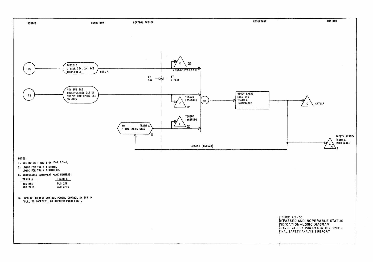
SOURCE CONDITION
ACB2EIO DIESEL GEN. 2-1 ACB INOPERABLE NOTE ~
MOTES: I, SEE NOTES I AND 2 ON FIG. 7. 5-1,
2. LOGIC FOR TRAIN A SHOWN, LOGIC FOR TRAIN B SIMILAR,
3. ASSOCIATED EQUIPMENT MARK NUMBERS: TRAIN A BUS 2AE ACB 2EIO
TRAIN B BUS 2DF ACB 2FIO
~. LOSS OF BREAKER CONTROL POWER, CONTROL SWITCH IN "PULL TO LOCKOUT", OR BREAKER RACKED OUT,
CONTROL ACTION
BY S&W -+ BY
OTHERS
Y5557D (Y56~1W)
'---~Sf
Y5561W (Y56510)
~160V El!tERG ELEC SYS
t-------1~ TRA llf A INOPERABLE
A5565D { A5652D}
RESULTANT
fiGURE 7.5-30
MONITOR
SAFETY SYSTEN TRAIN A INOPERABLE
~...,,...J._...)§
9YPASSED AND INOPERABLE STATUS INDICA TJON- LOGIC DIAGRAM $EAVER VALLEY POWER STATION-UNIT 2 ~INAL SAFETY ANALYSIS REPORT
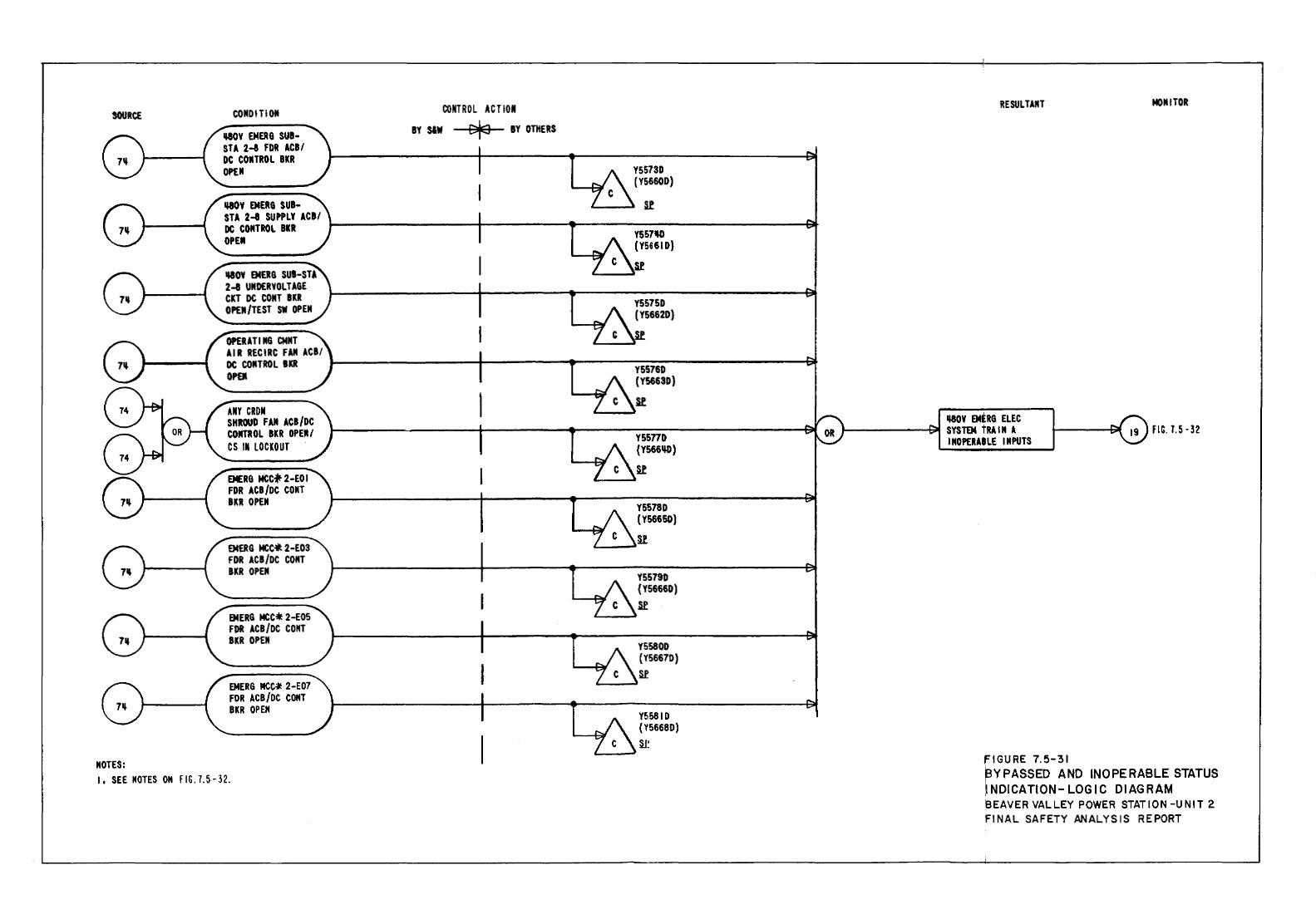
SOURCE
NOTES:
CONDITION
IWJY EMEJIG SUB-STA 2-1 FDR ACB/ DC COMTROL BlR OPU
1180Y EMERG SUI-STA 2-8 SUPPLY ACB/ DC CONTROL BlR OPU
IIIOY EMERG SUB-STA 2-8 UNDERYOLTAGE Cll DC CONT BKR OPEM/TEST SW OPEN
OPEUT I NG CMNT AIR RECIRC FAN ACB/
CONTROl ACT ION
BY S&W ~ BY OTHERS
Y5573D (Y5660D)
Sl
Y557'1) (Y5661D}
&e &..--~
DC CONTROLBO ~----------------~----------~--------Y~S~~~6~0 ------------------~ OPal ( Y5663D}
ANY CRDM SHROUD FAN ACB/DC CONTROL BKR OPEM/ CS 11 lOClOUT
EMERG MCC* 2-EO I FOR ACB/DC COMT BlR OPEN
EMERG MCC.ft. 2-EOS FOR ACB/DC COMT BKR OPEN
EMERG MCC* 2-EOS FOR ACB/OC COIIT BKR OPEII
EMERG MCC~ 2-E07 FOR ACB/DC CONT BKR OPEH
R
yssno (Y566~)
R
Y5578D {Y56650)
'--~n
Y5579D {Y56660) ~
Y5580D (Y5667D) Sf
Y5581D (Y5668D) ~
I, SEE NOTES OM FIG.7.5-32.
RESULTANT
II-80Y OORG ELEC J--------911 SYSTEM tRAIN A
I NOPERA8LE INPUTS
FIGURE 7.5-31
MONITOR
~YPASSED AND INOPERABLE STATUS ~INDICATION- LOGIC DIAGRAM 'BEAVER VALLEY POWER STATION-UNIT 2 FINAL SAFETY ANALYSIS REPORT
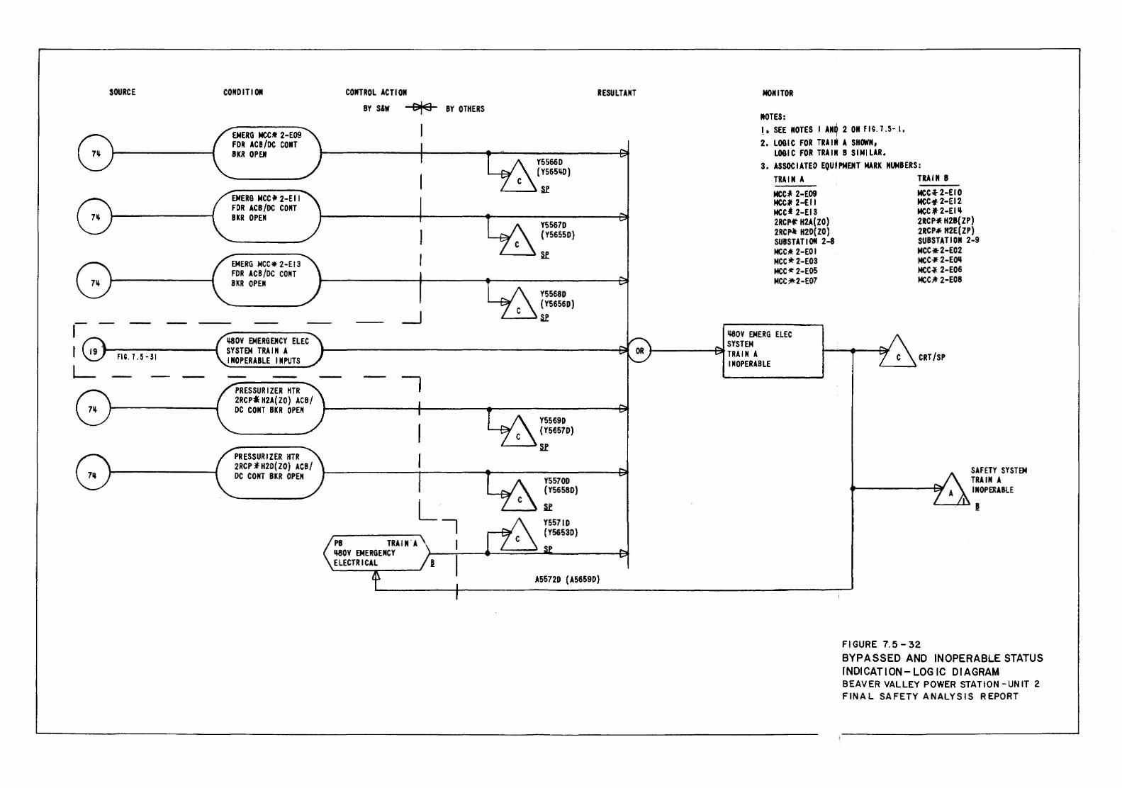
SOURCE
,--m.r.5-31
CONDIT! ON
EMERG MCCM 2-E09 FOR ACB/DC CONT BKR OPEN
EMERG MCC * 2-E II FOR ACB/DC CONT BKR OPEN
EMERG MCC* 2-Et3 FOR ACB/DC CONT BKR OPEN
LI80V EMERGENCY ELEC SYSTEM TRAIN A INOPERABLE INPUTS
PRESSURIZER HTR 2RCP:l H2A(ZO) ACB/ DC CONT BKR OPEN
PRESSURIZER itTR 2RCP :f- H2D(ZO) ACB/ DC COHT BKR OPEN
CONTROL ACTION
BY S&W ora I
_j
PB TRAIN'A LI80V EMERGENCY ELECTRICAL l
RESULTANT
BY OTHERS
Y5566D (Y5651W)
Sl
Y5567D {Y5655D)
s..e
Y5568D {Y5656D)
s..e
Y5569D { Y5657D)
L---Ju
A5572D (A5659D)
MONITOR
MOTES: I
lo SEE MOTES I AMO 2OM fl,. 7.5-1, - I
2. LOGIC FOR TRAIN A SHOWM, LOGIC FOR TRAIN B SIMILAR.
3. ASSOCIATED EQUIPMENT MARK NliiBERS: TRAIN A
MCCI2-E09 MCC# 2-EII Meet 2-E13 2RCp-J" H2A(ZO) 2RCfll- H2D{ZO) SUBSTATION 2-8 MCC:t 2-EDI MCC*2-E03 MCC:!f 2-E05 MCC:*2-E07
LI80V EMERG ELEC SYSTEM
t--------1~ TRAIN A INOPERABLE
TRAIN 8
MCC~2-EIO MCC·2-EI2 MCC" 2-EI ~ 2RCP-* H28{ZP) 2RCP#< H2E{ZP) SUBSTATION 2-9 MCC•2-E02 MCC-J- 2-EOIJ MCC.,J_ 2-E06 MCC;lt 2-EOS
CRT/SP
Fl GURE 7.5-32
SAFETY SYSTEM TRAIN A INOPERABLE
BYPASSED AND INOPERABLE STATUS rNDICATION- LOGIC DIAGRAM BEAVER VALLEY POWER STATION -UN IT 2 FINAL SAFETY ANALYSIS REPORT
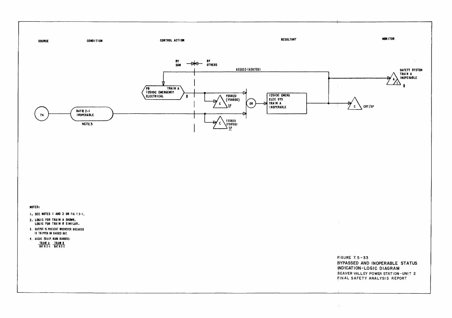
SOURCE COIIDITIOII
an• 2-1 INOPERABLE
NOTE3
IIOTES:
1, SEE NOTES I AIIO 2 ON FIU.5-I.
2. LOGIC FOR TRAIN A SHOWN, LOGIC FOR TRAIN B SIMILAR.
3. OUTPUT IS PRESEU JHENEVER BREAKER I S TRI PPEO OR RACKED 011 T.
4. ASSOC. EQUIP. IIARI NUMBERS: TRAil A TRAI I BAH 2-1 BA 112-2
COIITROL ACTIOII
BY S&W
PB TRAIN A 125VDC EMERGENCY ELECTRICAL
BY OTHERS
RESULTANT
A5583 D U5670D l
y 55830 (Y5670DJ
'---~ SP
125VDC EMERG ELEC SYS
~-Bt TRAIN A INOPERABLE
MOliTOR
FIGURE 7. 5-33
SAFETY SYSTEM TRAIN A INOPERABLE
I
BYPASSED AND INOPERABLE STATUS 'NDICATION-LOGIC DIAGRAM BEAVER VALLEY POWER STATION-UNIT 2 FINAL SAFETY ANALYSIS REPORT
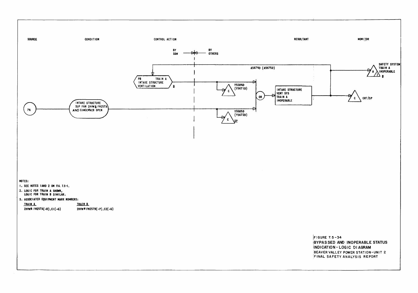
SOURCE CONI> IT ION
INTAKE STRUCTURE
CONTROL ACTION
PB TRAIN A INTAKE STRUCTURE
BY S&W
VENTILATION §
BY OTHERS
RESutTANT
A567~0 (A56750)
Y55B~O
(Y56710) INTAKE STRUCTURE VENT SYS
1--~TRAIN A INOPERABLE
SUP FAN 2HVW* FN257A AND CIMCCfl.CB OPEN .,_-----------------+----...----Y~S-::-58-:-:5:-0----t;:;l
MOTES: I • SEE NOTES I AND 2 OM m. 1.5-1. 2. LOGIC FOR TRAIN A SHOWM,
LOGIC FOR TRAIN B SIMILAR. 3. ASSOCIATED EQUIPMENT MARK NUMBERS:
TRAIN A TRAIN B 2HVW* FM257A(-D},CI(-G) 2HVW * FN257B( -P) , C2( -G)
(Y5672D)
MONIJ_OR
CRT /SP
FIGURE 7.5-34
SAFETY SYSTEM TRAI M A INOPERABLE
I I
BYPASSED AND INOPERABLE STATUS NDICATION- LOGIC Dl AGRAM
BEAVER VALLEY POWER STATION-UNIT 2 ·;FINAL SAFETY ANALYSIS REPORT
BVPS-2 UFSAR Rev. 16
7.6-1
7.6 ALL OTHER SYSTEMS REQUIRED FOR SAFETY 7.6.1 Instrumentation and Control Power Supply System 7.6.1.1 Description The following is a description of the instrumentation and control power supply system:
1. Figure 7.6-1 gives a single line diagram of the instrumentation and control power supply system.
2. There are four inverters and their associated distribution
panels. Each inverter is connected independently to one or more distribution panels.
3. The inverters provide a source of 118 V 60 Hz power for the
operation of the nuclear steam supply system instrumentation. This power is derived from the 480 V ac, three-phase, 60 Hz distribution system (preferred power supply), or the station batteries, which assure continued operation of instrumentation systems in the event of a station blackout.
4. Each of the four sets of distribution panels may be connected
to a backup source of 120 V ac power. The tie is through a local electrically-operated manual bypass switch, which is mechanically interlocked with the breaker connecting the inverter to the distribution panel such that the distribution panels cannot be connected to both sources simultaneously.
7.6.1.2 Analysis There are two independent 480 V ac power sources, each serving two inverters. Loss of either 480 V ac power source affects only two of the four inverters. There are four independent batteries. Each of the batteries are supplied with independent battery chargers. Since not more than two inverters are connected to the same bus, a loss of a single bus can only affect two of the four inverters. Each inverter is independently connected to its respective vital bus distribution panels so that loss of an inverter cannot affect more than one of the four sets of vital bus distribution panels.
BVPS-2 UFSAR Rev. 10
7.6-2
Each of the four sets of vital bus distribution panels is connected to a backup 120 V ac power source. Each panel can receive power from the 120 V ac backup source under administrative control. The manual bypass switch is interlocked to prevent paralleling of the inverters with the backup source. No single failure in the instrument and control power supply system or its associated power supplies can cause a loss of power to more than one redundant load. The inverters are designed to maintain their outputs within acceptable limits. The loss of the ac or dc inputs is alarmed in the main control room, as is the loss of an inverter output. There are no inverter breaker controls on the control board, as no manual transfers are necessary in the event of loss of the 480 V ac preferred power source. Physical separation and provisions to protect against fire are discussed in Chapter 8. The criteria applicable to the instrumentation and controls power supply system are based on the scope definitions presented in the Institute of Electrical and Electronics Engineers (IEEE) Standard 308-1974. The design is in compliance with IEEE Standard 308-1974 and Regulatory Guide 1.6. Availability of this system is continuously indicated by the operational status of the systems it serves (Figure 7.6-1) and is verified by periodic testing performed on the served systems. The inverters are seismically qualified in accordance with the qualification program described in Section 3.10. 7.6.2 Residual Heat Removal Isolation Valves 7.6.2.1 Description The residual heat removal (RHR) system isolation valves are normally closed and are only opened for RHR after system pressure is reduced to approximately 360 psig and system temperature has been reduced to approximately 350°F. They are the same type of valve and motor operator as those used for accumulator isolation, but they differ in their controls and in their indications in the following respect: The RHR valves are provided with control switches that have red (open) and green (closed) position indicating lights located on the main control board and emergency shutdown panel (ESP). These lights are powered by valve control power and actuated by valve motor operator limit switches. There are two motor-operated valves (MOVs) in series in each of the two RHR pump suction lines from the reactor coolant system (RCS) hot legs, and one MOV in each of the two RHR discharge lines. The two valves nearest the RCS (702A&B) are designated as the inner isolation
BVPS-2 UFSAR Rev. 12
7.6-3
valves, while the two valves nearest the RHR pumps (701A&B) are designated as the outer isolation valves. The valves in the discharge line are designated 720A&B. The interlock functions, provided for the outer isolation valves and discharge valve 720A shown on Figure 7.6-2, are identical (though derived from a diverse transmitter) to those provided for the inner isolation valves and discharge valve 720B shown on Figure 7.6-3. Each valve is interlocked so that it cannot be opened unless the RCS pressure is below approximately 360 psig. This interlock prevents the valve from being opened when the RCS pressure plus the RHR pump pressure would be above the RHR system design pressure. A second pressure interlock is provided to close the valve automatically if the RCS pressure subsequently increases to above approximately 700 psig. The pressure functions shown on Figure 7.6-3 are derived from a pressure transmitter designated PT441, which is supplied from a different vendor than the transmitter designated PT440 from which the pressure functions shown on Figure 7.6-2 are derived. This is the method used to achieve diversity. The autoclosure interlock may be manually defeated during normal RHR operation to prevent inadvertent RHR isolation valve closure. All four MOVs in the RHR suction lines are powered from Class lE power sources. Two of the four MOVs (one in each suction line) are powered from two separate Class lE power sources. This redundancy assures that the suction line to the RHR pump can be isolated when RCS pressure is above the preset value. In order to ensure that an RHR pump is available when required and one of the redundant power sources is not available, provisions are made to transfer power to the other Class lE redundant power source. This will allow opening of the two series valves in one of the RHR pump suction lines. Interlocks are provided to prevent paralleling of the two Class lE power sources. 7.6.2.2 Analysis Based on the scope definitions presented in the IEEE Standards 279-1971 and 308-1974, these criteria do not apply to the RHR isolation valve interlocks. However, in order to meet the U.S. Nuclear Regulatory Commission (USNRC) requirements and because of the possible severity of the consequences of loss of function, the following requirements of IEEE Standard 279-1971 apply to this circuit:
1. For the purpose of applying IEEE Standard 279-1971 to this circuit, the following-definitions will be used:
a. Protection system
The two valves in series in each 1ine and al1 components of their interlocking and closure circuits.
BVPS-2 UFSAR Rev. 0
7.6-4
b. Protective action The automatic initiation and maintenance of RHR system
isolation from the RCS pressures above the preset value.
2. Paragraph 4.10 of IEEE Standard 279-1971: The preceding pressure interlock signals and logic will be tested on-line to the maximum extent possible without adversely affecting safety. This test will include the analog signal through to the output relay (which provides the final output signal to the valve control circuit) by observing that the armature of the output relay has changed state. (Test does not include provisions available from safeguard test cabinet.) This is done in the best interests of safety since an actual actuation (opening) of the valve could potentially leave only one remaining valve to isolate the low pressure RHR system from the RCS.
3. Paragraph 4.15 of IEEE Standard 279-1971: This requirement
does not apply, as the set points are independent of the mode of the operation and are not changed.
Environmental qualification of the valves and wiring is discussed in Section 3.11. 7.6.3 Refueling Interlocks Electrical interlocks (limit switches), as discussed in Section 9.1.3, are provided for minimizing the possibility of damage to the fuel during fuel handling operations. 7.6.4 Accumulator Motor-Operated Valves The design of the interconnecting of these signals to the accumulator isolation valve meets the following criteria established in previous USNRC positions on this matter:
1. Automatic opening of the accumulator valves when, a) the primary coolant system pressure exceeds a preselected value (to be specified in the Technical Specifications), or b) a safety injection (SI) signal has been initiated. Both signals shall be provided to the valves.
2. Utilization of an SI signal to automatically remove
(override) any bypass features that are provided to allow an isolation valve to be closed for short periods of time when the RCS is at pressure (in accordance with the provisions of the proposed Technical Specifications). As a result of the confirmatory SI signal, isolation of an accumulator with the reactor at pressure is acceptable.
BVPS-2 UFSAR Rev. 0
7.6-5
The control circuit for these valves is shown on Figure 7.6-4. The valves and control circuits are further discussed in Sections 6.3.2 and 6.3.5. The SI system accumulator discharge isolation MOVs are normally open valves which are controlled from the main control board and the ESP. These valves are interlocked such that:
1. They open automatically on receipt of an SI signal with the main control board switch in either the auto or close position.
2. They open automatically whenever the RCS pressure is above
the SI unblock pressure (P-11) specified in the Technical Specifications only when the main control board switch is in the auto position.
3. They cannot be closed as long as an SI signal is present. 4. Power to valves is removed during normal plant operation to
prevent inadvertent or spurious closure of the valves. The three main control board and ESP control switches for these valves provide a spring return to auto from the open position and a maintain position in close. The maintain closed position is required to provide an administratively controlled manual block of the automatic opening of the valve at pressure above the SI unblock pressure (P-11]. The manual block or maintain closed position is required when performing periodic check valve leakage test when reactor is at pressure. The maximum permissible time that an accumulator valve can be closed when the reactor is at pressure is specified in the Technical Specifications. Administrative control is required to ensure that any accumulator valve, which has been closed at pressures above the SI unblock pressure, is returned to the auto position. Verification that the valve automatically returns to its normal full open position would also be required. During Beaver Valley Power Station - Unit 2 (BVPS-2) shutdown, the accumulator valves are in a closed position. To prevent an inadvertent opening of these valves during that period, the accumulator valve breakers should be opened or removed. Administrative control is again required to ensure that these valve breakers are closed during the prestart-up procedures. These normally open MOVs have alarms to indicate a malpositioning (with regard to their emergency core cooling system (ECCS) function during the injection phase). The alarms sound in the main control room.
BVPS-2 UFSAR Rev. 0
7.6-6
An alarm will sound for either accumulator isolation valve under the following conditions when the RCS pressure is above the SI unblocking pressure:
1. Valve stem limit switch indicates valve not open, 2. Valve motor operator limit switch indicates valve not open.
The alarms on this switch will repeat themselves at given intervals.
7.6.5 Switchover from Injection to Recirculation
During the initial injection phase following an accident, the refueling water storage tank (RWST) is used to supply borated water to the ECCS pumps. The changeover from the injection to the recirculation mode is initiated automatically. Protection logic is provided to automatically open the low head safety injection (LHSI) recirculation supply isolation valves when the RWST water level reaches a predetermined extreme low level set point, in conjunction with the initiation of the SI engineered safety features actuation signals, and automatic switchover will be as follows:
1. The RWST 2/4 extreme low level coupled with a latched-in SI
signal will automatically open valves 8811A/B (Figure 7.6-8, Sheets 1, 2, 3, 4, 5) connecting the recirculation pump discharge to the LHSI pump discharge lines. When valves 8811A/B are full open, the associated LHSI pump will be tripped (Figure 7.6-8, Sheet 3 shows pump tripping).
2. Similarly, the LHSI header cross-connect valves 8887A/B
(Figure 7.6-8, Sheet 4) will be automatically closed and valves 8812A/B (Figure 7.6-8, Sheet 5) supplying the suction of the charging/safety injection system will be automatically opened provided 8811A/B are fully open.
In the event that a SI signal is generated, these interlocks provide for the retention of that signal by latching relays. The retention of this signal is required since the emergency procedures would instruct the operator to reset the safeguards actuation signal at a time significantly in advance of the RWST low level setpoint signal generation. The details of achieving cold leg recirculation following SI are given in Section 6.3.2 and Table 6.3-7. Figure 7.6-8, Sheet 2, shows the logic which is used to automatically open the sump valves. 7.6.6 Reactor Coolant System Loop Isolation Valve Interlocks
Description The purpose of these interlocks is to ensure that an accidental start-up of an unborated and/or cold, isolated reactor coolant loop results only in a relatively slow reactivity insertion rate.
BVPS-2 UFSAR Rev. 12
7.6-7
The interlocks (refer to Figure 7.2-1, Sheet 16, for interlock logic functions) are required to perform a protective function. Therefore, there are:
1. A limit switch to indicate that a valve is fully open. 2. A limit switch to indicate that a valve is fully closed.
3. Two differential pressure switches in each line which bypasses a cold leg loop isolation valve. This is the line which contains the relief line isolation valve. It should be noted that flow through the relief line isolation valves indicates that: 1) the valves in the line are open, 2) the line is not blocked, and 3) the pump is running.
7.6.7 Interlocks for RCS Pressure Control During Low Temperature
Operation The basic function of the RCS pressure control during low temperature operation is discussed in Section 5.2.2. This pressure control includes semi-automatic actuation logic for two (of the three) pressurizer power-operated relief valves (PORVs). The function of this actuation logic is to continuously monitor RCS temperature and pressure conditions, with actuation logic armed by operator action by means of an arm/block main control board switch which is placed in the block position when BVPS-2 is at operating pressure. The monitored system temperature signals are processed to generate the reference pressure limit, which is compared to the actual monitored RCS pressure. This comparison will provide an actuation signal to an actuation device which, if manually armed, will cause the PORV to automatically open, as necessary, to prevent pressure conditions from exceeding allowable limits. Refer to Figure 7.2-1, Sheets 17 and 18, for the diagrams showing the basic elements used to process the generating station variables for this low temperature RCS overpressurization preventive interlocks. Sheets 7.2-1, Sheets 17 and 18 are the functional diagrams for PORV and block valves
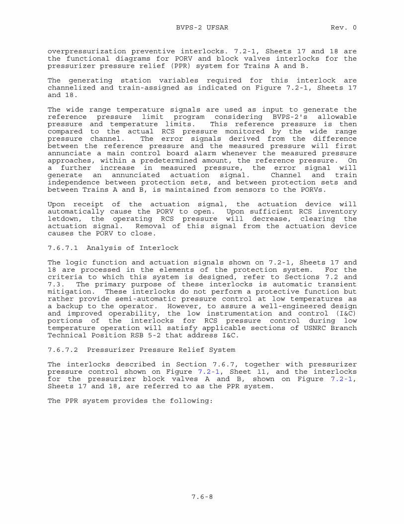
BVPS-2 UFSAR Rev. 0
7.6-8
overpressurization preventive interlocks. 7.2-1, Sheets 17 and 18 are the functional diagrams for PORV and block valves interlocks for the pressurizer pressure relief (PPR) system for Trains A and B. The generating station variables required for this interlock are channelized and train-assigned as indicated on Figure 7.2-1, Sheets 17 and 18. The wide range temperature signals are used as input to generate the reference pressure limit program considering BVPS-2's allowable pressure and temperature limits. This reference pressure is then compared to the actual RCS pressure monitored by the wide range pressure channel. The error signals derived from the difference between the reference pressure and the measured pressure will first annunciate a main control board alarm whenever the measured pressure approaches, within a predetermined amount, the reference pressure. On a further increase in measured pressure, the error signal will generate an annunciated actuation signal. Channel and train independence between protection sets, and between protection sets and between Trains A and B, is maintained from sensors to the PORVs. Upon receipt of the actuation signal, the actuation device will automatically cause the PORV to open. Upon sufficient RCS inventory letdown, the operating RCS pressure will decrease, clearing the actuation signal. Removal of this signal from the actuation device causes the PORV to close. 7.6.7.1 Analysis of Interlock The logic function and actuation signals shown on 7.2-1, Sheets 17 and 18 are processed in the elements of the protection system. For the criteria to which this system is designed, refer to Sections 7.2 and 7.3. The primary purpose of these interlocks is automatic transient mitigation. These interlocks do not perform a protective function but rather provide semi-automatic pressure control at low temperatures as a backup to the operator. However, to assure a well-engineered design and improved operability, the low instrumentation and control (I&C) portions of the interlocks for RCS pressure control during low temperature operation will satisfy applicable sections of USNRC Branch Technical Position RSB 5-2 that address I&C. 7.6.7.2 Pressurizer Pressure Relief System The interlocks described in Section 7.6.7, together with pressurizer pressure control shown on Figure 7.2-1, Sheet 11, and the interlocks for the pressurizer block valves A and B, shown on Figure 7.2-1, Sheets 17 and 18, are referred to as the PPR system. The PPR system provides the following:
BVPS-2 UFSAR Rev. 17
7.6-8a
1. Capability for RCS overpressure mitigation during cold shutdown, heatup, and cooldown operations to minimize the potential for impairing reactor vessel integrity when operating at or near the vessel ductility limits and the system is manually armed.
2. Capability for RCS depressurization following Condition II,
III, and IV events. 3. An interlock that, with the pressurizer PORVs and PORV block
valves in auto control, closes the PORV block valves and prevents spurious signals from the PPR control system from inadvertently opening the PORVs when pressurizer pressure is low and the system in not manually armed.
7.6.7.3 Description of PPR System Interlock Interlocks for the PPR system control the opening and closing of the pressurizer PORVs and the PORV block valves. These interlocks provide the following functions:
1. Pressurizer pressure control, 2. RCS pressure control during low temperature operation, and 3. RCS pressure control to achieve and maintain a cold shutdown
and to heat up using equipment that is required for safety.
The interlock functions that provide pressurizer pressure control are derived from process parameters as shown on Figure 7.2-1, Sheets 6 and 11. The interlock logic functions as well as process parameter inputs required for low temperature operation are shown on Figure 7.2-1, Sheet 17 and 18. The functions include those needed for the PORV block valves as well as the pressurizer PORVs to meet both interlock logic and manual operation requirements where manual operation is at the main control board. 7.6.7.4 Service Water System Isolation Valves to the Turbine Plant
Component Cooling Water Heat Exchangers The service water system isolation valves to the turbine plant component cooling water heat exchangers (2SWS-MOV107A through D) perform the safety function of isolating the safety-related portion of the service water system from the nonsafety portion in the event of a CIA signal. This portion of the circuitry is designed to IEEE Standard 279-1971. Two service water system isolation valves (2SWS- MOV107A and D) also isolate the safety-related portion of the service water system from the nonsafety portion in the event of a service water low pressure signal. This portion of the circuit does not conform entirely to IEEE Standard 279-1971 in that the guidance of its Sections 4.10, 4.17, 4.19, and 4.20 are not met. Since this additional function (low pressure isolation) is not a signal "... that actuate(s) reactor trip ..." or a signal "... that,

BVPS-2 UFSAR Rev. 12
7.6-8b
in the event of a serious reactor accident, actuate (s) engineered safeguards such as containment isolation…”, conformance with IEEE Standard 279-1971 is not considered to be required. This portion of the circuit does, however, conform with IEEE Standard 279-1971 in areas other than those listed above.
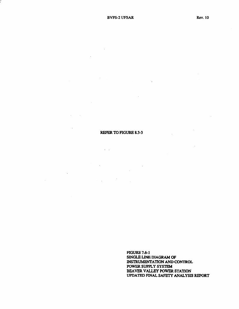
BVPS-2 UFSAR
REFER TO FIGURE 8.3-3
FIGURE 7.6-1 SINGLE LINE DIAGRAM OF INSlRUMENTATION AND CONlROL POWER SUPPLY SYSTEM
Rev. 10
BEAVER VALLEY POWER STATION UPDA1ED FINAL SAFETY ANALYSIS REPORT
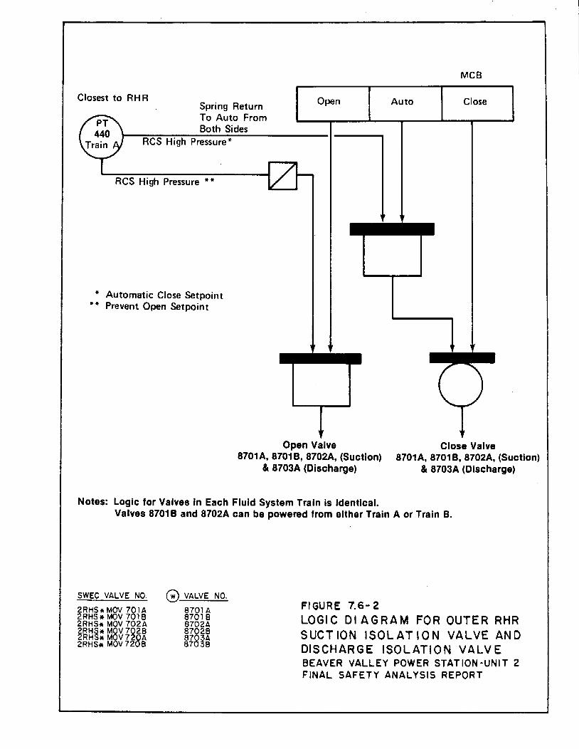
Closest to RH R Spring Return To Auto From Both Sides
RCS High Pressure*
RCS High Pressure **
* Automatic Close Setpoint ** Prevent Open Setpoint
MCB
Open Auto Close
Open Valve Close Valve 8701 A, 8701 B, 8702A, (Suction)
& 8703A (Discharge) 8701 A, 8701 B, 8702A, (Suction)
& 8703A (Discharge)
Notes: Logic for Valves In Each Fluid System Train is Identical. Valves 8701 B and 8702A can be powered from either Train A or Train B.
SWEC VALVE NO.
2RHS* MOV 781A 2RHS* MOV 7 18 2RHS* MOV 702A 2RHS* M§V 7028 2RHS* M V 728A 2RHS* M V72 8
G VALVE NO.
8781 A 87 18 8702A 87028 ~i8~~
FIGURE 7.6-2 LOGIC 01 AGRAM FOR OUTER RHR SUCTION ISOLATION VALVE AND DISCHARGE ISOLATION VALVE BEAVER VALLEY POWER STATION-UNIT 2 FINAL SAFETY ANALYSIS REPORT
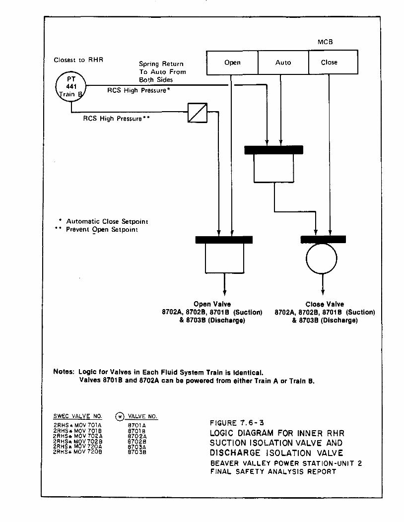
Closest to RHR Spring Return To Auto From Both Sides
RCS High Pressure*
RCS High Pressure**
* Automatic Close Setpoint ** Prevent 9pen Setpoint
MCB
Open Auto Close
Open Valve Close Valve 8702A, 87028, 8701 B (Suction)
& 87038 (Discharge) 8702A, 87028, 8701 B (Suction)
& 87038 (Discharge)
Notes: Logic for Valves in Each Fluid System Train is Identical. Valves 87018 and 8702A can be powered from either Train A or Train B.
SWEC VALVE NO. 2RHS* MOV 701A 2RHS* MOV 7018 2RHS* MOV 702A 2RHS* M8V7028 2RHS• M V 720A 2RHS* MOV 7208
0 VALVE NO. 8701A 87018 8702A 87028 8703A 87038
FIGURE 7. 6-3 LOGIC DIAGRAM FOR INNER RHR SUCTION ISOLATION VALVE AND DISCHARGE ISOLATION VALVE BEAVER VALLEY POWER STATION-UNIT 2 FINAL SAFETY ANALYSIS REPORT
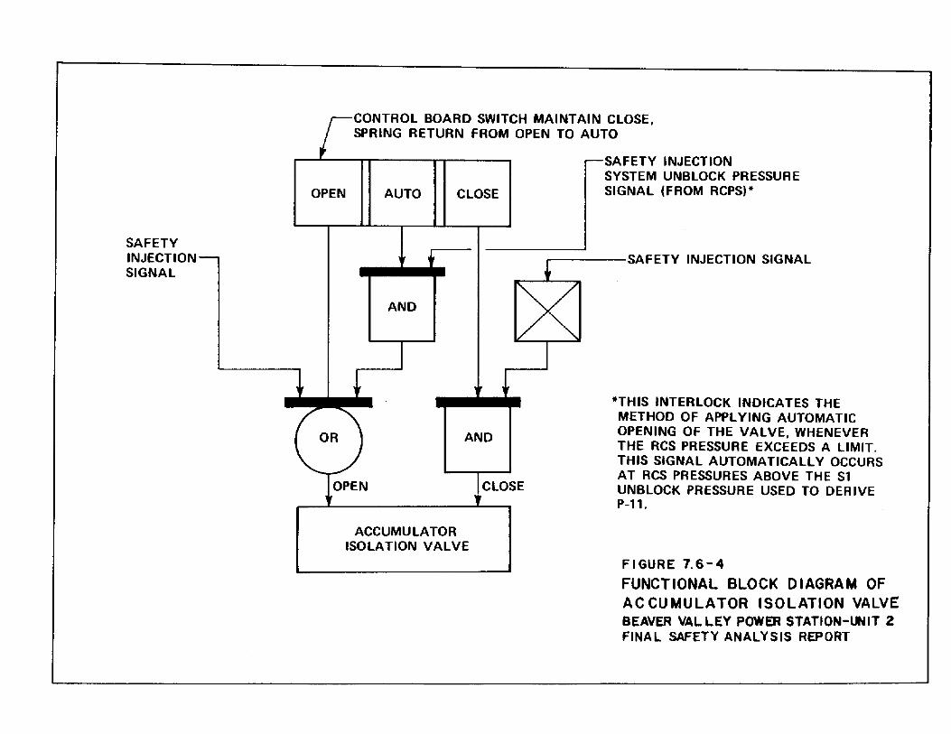
SAFETY INJECTION SIGNAL
OPEN
CONTROL BOARD SWITCH MAINTAIN CLOSE, SPRING RETURN FROM OPEN TO AUTO
AUTO CLOSE
AND
AND
CLOSE
ACCUMULATOR ISOLATION VALVE
SAFETY INJECTION SYSTEM UNBLOCK PRESSURE SIGNAL (FROM RCPS)*
...------SAFETY INJECTION SIGNAL
*THIS INTERLOCK INDICATES THE METHOD OF APPLYING AUTOMATIC OPENING OF THE VALVE, WHENEVER THE RCS PRESSURE EXCEEDS A LIMIT. THIS SIGNAL AUTOMATICALLY OCCURS AT RCS PRESSURES ABOVE THE Sl UNBLOCK PRESSURE USED TO DERIVE P-11.
Fl GURE 7.6-4 FUNCTIONAL BLOCK DIAGRAM OF AC CU MULA TOR ISOLATION VALVE BEAVER VAL LEY POWER STATION-lMIT 2 FINAL SAFETY ANALYSIS REPORT
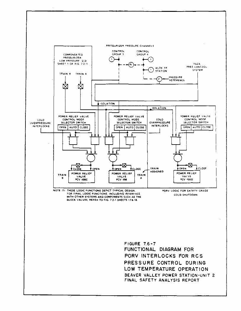
COLD OVERPRESSURE
INTERLOCKS
CDMPENSA TE 0 PRESSURIZER
LOW PRESSURE 12:31 S~HT 1 OF FIG 7 2-11
1 RAIN B TRAIN A
TRAIN 8
POWER RELIEF VALVE
PCV 455C
PRESSURIZER P!IESSURE C~ANNELS
CONTROL CONTROL GROUP J GROUP 4
0-t ~ +- _ ....J'A0---+ PAl A
I ~ ..__ __ /7\ ALQK F~ PRES CONT;'iOL ~ STATION SYSTEM
I I I L - PRESSURE
1--------f REFERENCE
ISOLATION
POWER REI.IEF VALVE
PCV 456
TRAIN A
ISOLATION
COLO OVERPRESSURE
INTERLOCKS
__j
TRAIN ASSIGNED
POWER RELIEF VALVE CONTROL MODE
SELECTOR SWITC~
POWER RELIEF VALVE
PCV 4S5D
NOTE 111 THESE LOGIC FUNCTIONS DEPICT TYPICAL DESIGN. PORV LOGIC FOR SAFETY GRADE
COLD SHUTDOWN FOR FINAL LOGIC FUNCTIONS. INCLUDING INTERFACE WITH OTHER SYSTEMS AND COMPONENTS SUCH AS THE BLOCK VALVES. REFER TO FIG. 72-1 SHEETS 17& 18.
FIGURE 7.6-7 FUNCTIONAL DIAGRAM FOR PORV INTERLOCKS FOR R C S PRESSURE CONTROL DURING LOW TEMPERATURE OPERATION BEAVER VALLEY POWER STATION-UNIT 2 FINAL SAFETY ANALYSIS REPORT
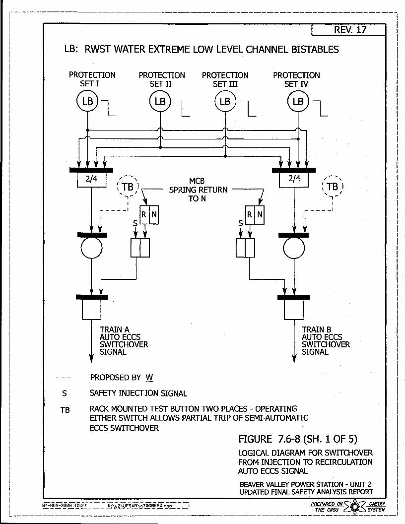
1---------------------------------------------------------------l
I REV. 17 l I l 1 LB: RWST WATER EXTREME LOW LEVEL CHANNEL BISTABLES l
l l PROTECTION PROTECTION PROTECTION PROTECTION I
SET I SET II SET III SET IV 1 I
s TB
2/4 / ' MCB 2/4 / ' ~TB'.----
, I ., ... SPRING RETURN --__, ~ TB I ' I ., ...
I r--- _I
TRAIN A AUTO ECCS SWITCH OVER SIGNAL
PROPOSED BY W
SAFETY INJECTION SIGNAL
TON I
r--- _I I I
TRAIN B AUTO ECCS SWITCH OVER SIGNAL
RACK MOUNTED TEST BUTTON TWO PlACES - OPERATING EITHER SWITCH ALLOWS PARTIAL TRIP OF SEMI-AUTOMATIC ECCS SWITCHOVER
FIGURE 7.6-8 (SH. 1 OF 5) LOGICAL DIAGRAM FOR SWITCHOVER FROM INJECTION TO RECIRCULATION AUTO ECCS SIGNAL BEAVER VALLEY POWER STATION - UNIT 2 UPDATED FINAL SAFElY ANALYSIS REPORT
I I I I I I I I I I I I I I I I I I I I I I I I I I I I I I I I I I I I I I I I I I I I I I I I I I I I I I I. I I I
lil4-NoV-200S10:27 --- K:\;;-2\UFSAR\;:;-7060080.d-;;~ -~ PREPAAED ON,#'t.,/ CAEDDI II --------- ----- - "'- --=--- THE CNSU c~:::..:t.~~ SfST"EM
L-----------------------------------------------------~------1
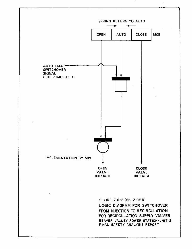
SPRING RETURN TO AUTO
OPEN AUTO CLOSE MCB
AUTO ECCS -------SWITCHOVER SIGNAL (FIG. 7.6-8 SHT. 1)
IMPLEMENTATION BY S/W
OPEN VALVE
881 1A(B)
CLOSE VALVE
8811A(B)
FIGURE 7.6-8 (SH. 2 OF 5)
LOGIC DIAGRAM FOR SWITCHOVER FROM INJECTION TO RECIRCULATION FOR RECIRCULATION SUPPLY VALVES BEAVER VALLEY POWER STATION-UNIT 2 FINAL SAFETY ANALYSIS REPORT
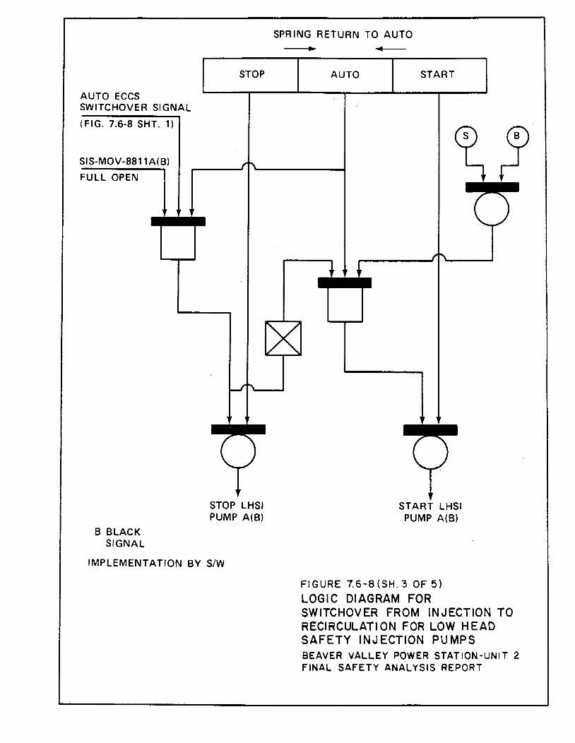
AUTO ECCS SWITCHOVER SIGNAL
(FIG. 7.6-8 SHT. 1)
SIS-MOV-8811A(B)
FULL OPEN
B BLACK SIGNAL
STOP
STOP LHSI PUMP A(B)
IMPLEMENTATION BY S/W
SPRING RETURN TO AUTO .. AUTO START
START LHSI PUMP A(B)
FIGURE 7.6-8(SH.3 OF 5) LOGIC DIAGRAM FOR SWITCHOVER FROM INJECTION TO RECIRCULATION FOR LOW HEAD SAFETY INJECTION PUMPS BEAVER VALLEY POWER STATION-UNIT 2 FINAL SAFETY ANALYSIS REPORT
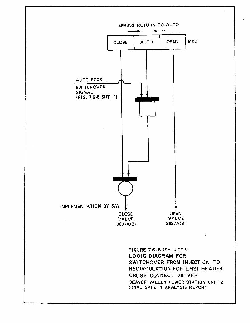
AUTO ECCS
SWITCHOVER SIGNAL
SPRING RETURN TO AUTO -.......;~~ ...,___
CLOSE AUTO OPEN MCB
(FIG. 7.6-8 SHT. 1)
IMPLEMENTATION BY S/W
CLOSE VALVE
8887A(B)
OPEN VALVE
8887A(B)
FIGURE 7.6 .. 8 (SH. 40F5) LOGIC DIAGRAM FOR SWITCHOVER FROM INJECTION TO RECIRCULATION FOR LHSI HEADER CROSS CONNECT VALVES BEAVER VALLEY POWER STATION-UNIT 2 FINAL SAFETY ANALYSIS REPORT
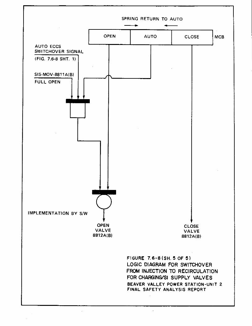
AUTO ECCS SWITCHOVER SIGNAL
(FIG. 7.6-8 SHT. 1)
SIS-MOV-881 1A(B)
FULL OPEN
IMPLEMENTATION BY S/W
OPEN
OPEN VALVE
8812A(B)
SPRING RETURN TO AUTO .. ... AUTO CLOSE
CLOSE VALVE
8812A(B)
Fl GURE 7. 6-8 (SH. 5 OF 5)
MCB
LOGIC DIAGRAM FOR SWITCHOVER FROM INJECTION TO RECIRCULATION FOR CHARGING/51 SUPPLY VALVES BEAVER VALLEY POWER STATION-UNIT 2 FINAL SAFETY ANALYSIS REPORT
BVPS-2 UFSAR Rev. 16
7.7-1
7.7 CONTROL SYSTEMS NOT REQUIRED FOR SAFETY The general design objectives of the Beaver Valley Power Station - Unit 2 (BVPS-2) control systems are:
1. To establish and maintain power equilibrium between primary and secondary system during steady state unit operation,
2. To constrain operational transients to preclude unit trip and
reestablish steady-state unit operation, and 3. To provide the reactor operator with monitor instrumentation
that indicates all required input and output control parameters of the systems.
4. To provide the operator the capability of assuming manual
control of the system. 7.7.1 Description The BVPS-2 control systems described in this section perform the following functions:
1. Reactor control system a. Enables the nuclear plant to accept a step load increase
or decrease of 10-percent and a ramp increase or decrease of 5-percent/min within the load range of 15 to 100-percent without reactor trip, steam dump, or pressurizer relief actuation, subject to possible xenon limitations.
b. Maintains reactor coolant average temperature Tavg within
prescribed limits by creating the bank demand signals for moving groups of rod cluster control assemblies (RCCAS) during normal operational transients. Automatic control rod insertion may be used for temperature (Tavg) control. However, rod withdrawal can only be performed manually due to the deletion of the automatic rod withdrawal capability. Manual control of rod operation may be performed at any time within the range of the defined insertion limits. The Tavg control also supplies a signal to pressurizer water level control and steam dump control.
2. Rod control system
a. Provides for reactor power modulation by manual or
automatic control (automatic rod insertion only) of control rod banks in a preselected sequence and for manual operation of individual banks.
b. Systems for monitoring and indicating
(1) Provide alarms to alert the operator if the
required core reactivity shutdown margin is not available due to excessive control rod insertion.
BVPS-2 UFSAR Rev. 16
7.7-2
(2) Permit display control rod positioning. (3) Provide alarms to alert the operator in the event
of control rod deviation exceeding a preset limit.
3. Control system interlocks
a. Prevent further withdrawal of the control banks when signal limits are approached that predict departure from nucleate boiling ratio (DNBR) limit or kw/ft limit.
b. Inhibit automatic turbine load change as required by the
nuclear steam supply system.
4. Pressurizer pressure control
Maintains or restores the pressurizer pressure to the design pressure (which is well within reactor trip and relief and safety valve actuation set point limits) following normal operational transients that induce pressure changes by control (manual or automatic) of heaters and spray in the pressurizer. Provides steam relief by controlling the pressurizer power-operated relief valves (PORVs).
5. Pressurizer water level control
Establishes, maintains, and restores pressurizer water level
within specified limits as a function of the average coolant temperature. Changes in water level are caused by coolant density changes induced by the change in Tavg as a function of load. Water level control is produced by charging flow control (manual or automatic), as well as by manual selection of letdown orifices. Maintaining coolant level in the pressurizer within prescribed limits provides for control of the reactor coolant water inventory.
6. Steam generator water level control
a. Establishes and maintains the steam generator water
level to within predetermined limits during normal operating transients.
b. Restores the steam generator water level to within
predetermined limits at unit trip conditions. Regulates the feedwater flow rate such that under operation transients the heat sink for the reactor coolant system (RCS) does not decrease below a minimum. Steam generator water inventory control is manual or automatic through the use of feedwater control valves.
BVPS-2 UFSAR Rev. 16
7.7-3
7. Steam dump control
a. Permits BVPS-2 to accept a sudden loss of load without incurring reactor trip. Steam is dumped to the condenser as necessary to accommodate excess power generation in the reactor during turbine load reduction transients.
b. Ensures that stored energy and residual heat are removed
following a reactor trip to bring BVPS-2 to equilibrium no load conditions without actuation of the steam generator safety valves.
c. Maintains BVPS-2 at no load conditions and permits a
manually controlled cooldown of the nuclear plant.
8. Incore instrumentation Provides information on the neutron flux distribution and on
the core outlet temperatures at selected core locations.
7.7.1.1 Reactor Control System The reactor control system enables BVPS-2 to follow load changes including the acceptance of step load increases or decreases of 10 percent, and ramp increases or decreases of 5 percent/min within the load range of 15 to 100 percent without reactor trip, steam dump, or pressure relief (subject to possible xenon limitations). The system is also capable of restoring coo1ant average temperature to within the programmed temperature deadband following a change in load. Manual control rod operation may be performed at any time. The reactor control system controls the reactor coolant average temperature by regulation of control rod bank position. The reactor coolant loop average temperatures are determined from hot leg and cold leg measurements in each reactor coolant loop. There is an average coolant temperature (Tavg) computed for each loop, where:
2)( coldavghot
avg
TTT
+= (7.7-1)
The error between the programmed reference temperature (based on turbine first stage pressure) and the median of the Tavg measured temperatures (which is processed through a lead-lag compensation unit) from each of the reactor coolant loops constitutes the primary control signal, as shown in general on Figure 7.7-1 and in more detail on the functional diagram, Figure 7.2-1, Sheet 9. The system is capable of restoring coolant average temperature to the programmed value following a change in load. The programmed coolant temperature increases linearly with turbine load from zero power to the full power condition. The median Tavg signal is also supplied to the pressurizer level control, steam dump control, and rod insertion limit monitoring control system.
BVPS-2 UFSAR Rev. 15
7.7-4
The temperature inputs to the control systems are derived using the median signal selector. An additional control input signal is derived from the reactor power versus turbine load mismatch signal. This additional control input signal improves system performance by enhancing response and reducing transient peaks. 7.7.1.2 Rod Control System 7.7.1.2.1 Rod Control System The rod control system receives rod speed and direction signals from the Tavg control system. The rod speed demand signal varies over the corresponding range of 8 to 72 steps/min depending on the magnitude of the input signal. Automatic rod withdrawal capabilities have been disabled for enhanced reactivity management. Manual control is provided to move a control bank in or out at a prescribed fixed speed. Rods are withdrawn (or inserted) in a predetermined programmed sequence by the automatic programming equipment. The manual and automatic controls are further interlocked with the control interlocks (Table 7.7-1). The shutdown banks are always in the fully withdrawn position during normal operation, and are moved to this position at a constant speed by manual control prior to criticality. A reactor trip signal causes them to fall by gravity into the core. There are two shutdown banks. The control banks are the only rods that can be manipulated under automatic control. Each control bank is divided into two groups to obtain smaller incremental reactivity changes per step. All RCCAs in a group are electrically paralleled to move simultaneously. There is individual position indication for each RCCA. Power to rod drive mechanisms is supplied by two motor-generator sets operating from two separate 480 V three-phase buses. Each generator is the synchronous type and is driven by a 200 hp induction motor. The ac power is distributed to the rod control power cabinets through the two series-connected reactor trip breakers.
BVPS-2 UFSAR Rev. 16
7.7-5
The variable speed rod drive programmer affords the ability to insert small amounts of reactivity at low speed to accomplish fine control of reactor coolant average temperature about a small temperature deadband, as well as furnishing control at high speed. A summary of the RCCA sequencing characteristics is given as follows:
1. Two groups within the same bank are stepped such that the relative position of the groups will not differ by more than one step.
2. The control banks are programmed such that withdrawal of the
banks is sequenced in the following order; control bank A, control bank B, control bank C, and control bank D. The programmed insertion sequence is the opposite of the withdrawal sequence, that is, the last control bank withdrawn (bank D) will be the first control bank inserted.
3. The control bank withdrawals are programmed such that when
the first bank reaches a preset position, the second bank begins to move out simultaneously with the first bank. When the first bank reaches the top of the core, it stops, while the second bank continues to move toward its fully withdrawn position. When the second bank reaches a preset position, the third bank begins to move out, and so on. This withdrawal sequence continues until the unit reaches the desired power level. The control bank insertion sequence is the opposite of the withdrawal sequence.
4. Overlap between successive control banks is adjustable
between 0 to 50-percent (0 to 115 steps), with an accuracy of +l step.
5. Rod speeds for either the shutdown banks or manual operation
of the control banks are capable of being controlled between a minimum of 8 steps/min and a maximum of 72 steps/min (+0 steps/min, -10 steps/min).
7.7.1.2.2 Rod Control System Features Credible rod control equipment malfunctions which could potentially cause inadvertent positive reactivity insertions due to inadvertent rod withdrawal, incorrect overlap, or malpositioning of the rods are as listed:
1. Failures in the manual rod controls:
a. Rod motion control switch (in-hold-out) b. Bank selector switch
2. Failures in the overlap and bank sequence program control:
BVPS-2 UFSAR Rev. 0
7.7-6
a. Logic cabinet systems b. Power supply systems
7.7.1.2.2.1 Failures in the Manual Rod Controls The rod motion control switch is a three-position lever switch. The three positions are: in, hold, and out. These positions are effective when the bank selector switch is in manual. Failure of the rod motion control switch (contacts failing shorted or activated relay failures) would have the potential, in the worst case, to produce positive reactivity insertion by rod withdrawal when the bank selector switch is in the manual position or in a position which selects one of the banks. When the bank selector switch is in the automatic position, the rods would obey the automatic commands and any failures in the rod motion control switch would have no effect on the rod motion regardless of whether the rod motion control switch is in the in, hold, or out position. In the case where the bank selector switch is selecting a bank and a failure occurs in the rod motion switch that would command the bank to move out even when the rod motion control switch was in an in or hold position, the selected bank could inadvertently withdraw. This failure is bounded in the safety analysis (Chapter 15) by the uncontrolled bank withdrawal subcritical and at power transients. A reactivity insertion of up to 75 pcm/sec is assumed in the analysis due to rod movement. This value of reactivity insertion rate is consistent with the withdrawal of two banks. A failure that can cause more than one group of four mechanisms to be moved at one time within a power cabinet is not a credible event, because the circuit arrangement for the moveable and lift coils would cause the current available to the mechanisms to divide equally between coils in the two groups (in a power supply). The drive mechanism is designed such that it will not operate on half-current. A second feature in this scenario would be the multiplexing failure detection circuit included in each power cabinet. This failure detection circuit would stop rod withdrawal (or insertion). The second case considered in the potential for inadvertent reactivity insertion due to possible failures is when the bank selector switch is in the manual position. Such a case could produce a failure in the rod motion control switch, a scenario where the rods could inadvertently withdraw in a programmed sequence. The overlap and bank sequence are programmed when the switch selection is in either automatic or manual. This scenario is also bounded by the reactivity values assumed in the accident analysis (Chapter 15). In this case, the operator can trip the reactor, or the protection system would trip the reactor via power range neutron flux-high or overtemperature ΔT.
BVPS-2 UFSAR Rev. 0
7.7-7
7.7.1.2.2.2 Failure of the Bank Selector Switch A failure of the bank selector switch produces no consequences when the in-hold-out switch is in the hold position. This is due to the following design feature:
The bank selector switch is series-wired with the in-hold-out lever switch for manual and individual control rod bank operation. With the in-hold-out lever switch in the hold position, the bank selector switch can be positioned without rod movement.
7.7.1.2.2.3 Failures in the Overlap and Bank Sequence Program Control The rod control system design prevents the movement of the groups out of sequence, as well as limiting the rate of reactivity insertion. The main feature that performs the function of preventing malpositioning produced by groups out of sequence is included in the block supervisory memory buffer and control. This circuitry accepts and stores the externally generated command signals. In the event of an out of sequence input command to the rods while they are in movement, this circuit will inhibit the buffer memory from accepting the command. If a change of signal command appears, this circuit would stop the system after allowing the slave cyclers to finish their current sequencing. Failure of the components related to this system will also produce insertion limit and rod deviation alarms (Sections 7.7.1.3.3 and 7.7.1.3.4, respectively). Failures within the system such as failures of supervisory logic cards, pulser cards, etc, will also cause an urgent alarm.
1. An urgent alarm will be followed by the following actions:
a. Automatic de-energizing of the lift coil and reduced current energizing of the stationary gripper coils and moveable gripper coils,
b. Activation of the alarm light, urgent failure, on the
power supply cabinet front panel, and c. Activation of rod control, urgent failure, annunciator
window in the main control room.
2. The urgent alarm is produced in general by:
a. Regulation failure detector, b. Phase failure detector, c. Logic error detector, d. Multiplexing error detector, and
BVPS-2 UFSAR Rev. 16
7.7-8
e. Interlock failure detector. 7.7.1.2.2.4 Logic Cabinet Failures The rod control system is designed to limit the rod speed control signal output to a value that will cause the pulser (logic cabinet) to drive the control rod driving mechanism at 72 steps/min. If a failure should occur in the pulses or the reactor control system, the highest stepping rate possible is 77 steps/min, which corresponds to one step every 780 ms. A commanded stepping rate higher than 77 steps/min would result in go pulses entering a slave cycler while it is sequencing its mechanisms through a 780 ms step. This condition stops the control bank motion automatically and alarms are activated locally and in the main control room. It also causes the affected slave cycler to reject further go pulses until it is reset. The positive reactivity insertion rates for failure modes are bounded by the Chapter 15 analysis assumptions. 7.7.1.2.2.5 Failures Causing Movement of the Rods Out of Sequence No single failure was discovered (Shopsky 1977) that would cause a rapid uncontrolled withdrawal of control bank D (taken as worst case) when operating in the automatic bank overlap control mode with the reactor at near full power output. The analysis revealed that many of the failures postulated were in a safe direction and that rod movement is blocked by the rod urgent alarm. 7.7.1.2.2.6 Power Supply System Failures Analysis of the power cabinet disclosed no single component failures that would cause the uncontrolled withdrawal of a group of rods serviced by the power cabinet. The analysis substantiates that the design of a power cabinet is fail-preferred in regards to a rod withdrawal accident if a component fails. The end results of the failure is either that of blocking rod movement or that of dropping an individual rod, or rods, or a group of rods. No failure with the power cabinet, which could cause erroneous drive mechanism operation, will remain undetected. Sufficient alarm monitoring (including an urgent alarm) is provided in the design of the power cabinet for fault detection of those failures which could cause erroneous operation of a group of mechanisms. As noted in the foregoing, diverse monitoring systems are available for detection of failures that cause the erroneous operation of an individual CRDM.
BVPS-2 UFSAR Rev. 16
7.7-9
7.7.1.2.2.7 Conclusion In summary, no single failure within the rod control system can cause either reactivity insertions or malpositioning of the control rods that would result in core thermal conditions not bounded by the analyses contained in Chapter 15. 7.7.1.3 Plant Control Signals for Monitoring and Indicating 7.7.1.3.1 Monitoring Functions Provided by Nuclear Instrumentation
System The power range channels are important because of their use in monitoring power distribution in the core within specified safe limits. They are used to measure power level, axial power imbalance, and radial power imbalance. These channels are capable of recording overpower excursions up to 200-percent of full power. Suitable alarms are derived from these signals, as described in the following discussion. The basic power range signals are:
1. Current from each upper section ionization chamber for each of the four power range detectors,
2. Current from each lower section ionization chamber for each
of the four power range detectors, and 3. Total current from each of the four power range detectors
(sum of the currents from top upper and lower section ionization chambers for each of the four power range detectors).
Derived from these basic signals are the following:
1. Indicated nuclear power (four signals). 2. Lower radial flux tilt alarm (ratio of the maximum of the
four lower ionization chamber currents to the average of the four lower ionization chamber currents).
3. Upper radial flux tilt alarm (ratio of the maximum of the
four upper ionization chamber currents to the average of the four upper ionization chamber currents).
4. Average flux deviation alarm (ratio of the maximum channel
power (total current for upper and lower sections to the minimum channel power of the four channels).
BVPS-2 UFSAR Rev. 15
7.7-10
5. Axial flux difference indication (ΔI) (upper ionization chamber current minus the lower ionization chamber current for each detector).
6. Axial offset deviation alarms (ratio of the difference
between the upper and lower ionization chamber currents for a detector to the sum of the upper and lower ionization chamber currents for that detector). This is done for each detector by the BVPS-2 computer.
Nuclear power and axial unbalance are selectable for recording. 7.7.1.3.2 Rod Position Monitoring of Control Rods Two separate systems are provided to sense and display control rod position as described below:
1. Digital Rod Position Indication System The digital rod position indication system measures the
actual position of each control and shutdown rod using a detector which consists of discrete coils mounted concentrically over a hollow tube. The tube fits over the rod travel housing. The coils are located axially along the tube and magnetically sense the position of the rod drive shaft as it approaches the detector coil location. For each detector, the coils are interlaced into two data channels and are connected to the containment electronics (data A and B) by separate multiconductor cables. By employing two separate channels of information, the digital rod position indication system can continue to function (at reduced accuracy) when one channel fails. Multiplexing is used to transmit the digital position signals from the containment electronics to the control board display unit.
There are four banks of control rods and two banks of
shutdown rods. Each bank contains eight rods. The rod positions for the control banks of rods are indicated
by columns of light-emitting diodes (LEDs) that illuminate in discrete steps at six-step intervals throughout the range of travel of each control rod. Since the shutdown rods are normally either at the bottom or fully withdrawn, the rod positions for the shutdown banks of rods are indicated in discrete steps in six-step intervals, from rod bottom to 18 steps and from 210 steps to 228 steps (actual indication at rod bottom and rod top positions). A single LED for each shutdown rod illuminates when that particular rod is in an intermediate position between the
BVPS-2 UFSAR Rev. 12
7.7-11
two discrete positions discussed above. The accuracy of indication is +4 steps throughout the range of travel for each control rod, and from rod bottom to 18 steps and from 210 steps to 228 steps for each shutdown rod.
Included in the system is a rod at bottom signal for each
shutdown rod and control rod that operates a local alarm and activates a control room annunciator when the rod is at the bottom position.
2. Demand Position System
The demand position system counts pulses generated in the rod drive control system to provide a digital readout of the demanded bank position.
The demand position and digital rod position indication systems are separate systems, but safety criteria were not involved in the separation, which was a result only of operational requirements. Operating procedures require the reactor operator to compare the demand and indicated (actual) readings from the rod position indication system to verify operation of the rod control system. 7.7.1.3.3 Control Bank Rod Insertion Monitoring When the reactor is critical, the normal indication of reactivity status in the core is the position of the control bank in relation to reactor power (as indicated by the RCS loop T) and coolant average temperature. These parameters are used to calculate insertion limits for the control banks. The purpose of the control bank rod insertion monitor is to give warning to the operator of excessive rod insertion. The insertion limit maintains sufficient core reactivity shutdown margin following reactor trip, provides a limit on the maximum inserted rod worth in the unlikely event of a hypothetical rod ejection, and limits rod insertion such that acceptable nuclear peaking factors are maintained. Since the amount of shutdown reactivity required for the design shutdown margin following a reactor trip increase with increasing power, the allowable rod insertion limits must be raised (the rods must be withdrawn further) with increasing power. Two parameters which are proportional to power are used as inputs to the insertion monitor. These are the ΔT between the hot leg and the cold leg, which is a direct function of reactor power, and Tavg, which is programmed as a function of power.
BVPS-2 UFSAR Rev. 12
7.7-12
The rod insertion limit monitor is a feature that alerts the operator to a reduced shutdown reactivity condition. The value for E is chosen such that the low-low alarm would normally be actuated before the insertion limit is reached. The value for D is chosen to allow the operator to follow normal boration procedures. Figure 7.7-2 shows a block diagram representation of the control rod bank insertion monitor. The monitor is shown in more detail on the functional diagram, Figure 7.2-1, Sheet 9. In addition to the rod insertion monitor for the control banks, the BVPS-2 computer, which monitors individual rod positions, provides an alarm that is associated with the rod deviation alarm discussed in Section 7.7.1.3.4. This alarm is provided to warn the operator if any shutdown RCCA leaves the fully withdrawn position. Rod insertion limits are established by:
1. Establishing the allowed rod reactivity insertion at full power consistent with the purposes given previously,
2. Establishing the differential reactivity worth of the control
rods when moved in normal sequence, 3. Establishing the change in reactivity with power level by
relating power level to rod position, or 4. Linearizing the resultant limit curve. All key nuclear
parameters in this procedure are measured as part of the initial and periodic physics testing program.
Any unexpected change in the position of the control bank under automatic control, or a change in coolant temperature under manual control, provides a direct and immediate indication of a change in the reactivity status of the reactor. In addition, samples are taken periodically of coolant boron concentration. Variation in concentration during core life provide an additional check on the reactivity statue of the reactor, including core depletion. 7.7.1.3.4 Rod Deviation Alarms The demanded and measured rod position signals are displayed on the main control board. They are also monitored by the BVPS-2 computer, which provides a visual printout and an audible alarm whenever an individual rod position signal deviates from the other rods in the bank by a preset limit. The alarm can be set with appropriate
BVPS-2 UFSAR Rev. 15
7.7-13
allowance for instrument error and within sufficiently narrow limits to preclude exceeding core design hot channel factors. Figure 7.7-3 is a block diagram of the rod deviation comparator and alarm system. 7.7.1.3.5 Rod Bottom Alarm A rod bottom signal for the control rods bistable in the analog rod position system is used to operate a control relay, which generates the rod bottom rod drop alarm. 7.7.1.4 Control System Interlocks The listing of the BVPS-2 control system interlocks, along with the description of their derivations and functions, is presented in Table 7.7-1. It is noted that the designation numbers for these interlocks are preceded by C. The development of these logic functions is shown in the functional diagrams, Figure 7.2-1, Sheets 9 to 16. 7.7.1.4.1 Rod Stops Rod stops are provided to prevent abnormal power conditions, which could result from excessive control rod withdrawal initiated by either a control system malfunction or operator violation of administrative procedures. Rod stops are the C-1, C-2, C-3, and C-4 control interlocks identified in Table 7.7-1. The C-3 rod stop, derived from overtemperature ΔT, and the C-4 rod stop, derived from overpower ΔT, are also used for turbine runback, which is discussed in the following section. 7.7.1.4.2 Automatic Turbine Load Runback Automatic turbine load runback is initiated by an approach to an overpower or overtemperature condition. This will prevent high power operation that might lead to an undesirable condition, which, if reached, will be protected by reactor trip. Turbine load reference reduction is initiated by either an overtemperature or overpower ΔT signal. Two out of three coincidence logic is used. A rod stop and turbine runback are initiated when ΔT > ΔTrod stop for both the overtemperature and the overpower condition.
BVPS-2 UFSAR Rev. 0
7.7-14
For either condition in general ΔTrod stop = ΔTsetpoint -Bp where: Bp = A set point bias ATsetpoint = The overtemperature ΔT reactor trip value and the
overpower ΔT reactor trip value for the two conditions.
The turbine runback is continued until ΔT is equal to or less than ΔT rod stop. This function serves to maintain an essentially constant margin to trip. 7.7.1.5 Pressurizer Pressure Control The RCS pressure is controlled by using either the heaters (in the water region) or the spray (in the steam region) of the pressurizer plus steam relief for large transients. The electric immersion heaters are located near the bottom of the pressurizer. A portion of the heater group is proportionally controlled to correct small pressure variations. These variations are due to heat losses, including heat losses due to a small continuous spray. The remaining (backup) heaters are turned on when the pressurizer pressure- controlled signal demands approximately 100-percent proportional heater power. The spray nozzles are located on the top of the pressurizer. Spray is initiated when the pressure controller spray demand signal is above a given set point. The spray rate increases proportionally with increasing spray demand signal until it reaches a maximum value. Steam condensed by the spray reduces the pressurizer pressure. A small continuous spray is normally maintained to reduce thermal stresses and thermal shock in the pressurizer spray line and to help maintain uniform water chemistry and temperature in the pressurizer. The pressurizer PORVs limit system pressure for large positive pressure transients. In the event of a large load reduction not exceeding the design plant load rejection capability, the pressurizer PORVs might be actuated for the most adverse conditions, for example, the most negative Doppler coefficient and the minimum incremental rod worth. The relief capacity of the pressurizer PORVs is sized large enough to limit the system pressure to prevent actuation of high pressure reactor trip for the preceding condition. A block diagram of the pressurizer pressure control system on Figure 7.7-4.
BVPS-2 UFSAR Rev. 14
7.7-15
7.7.1.6 Pressurizer Water Level Control The pressurizer operates by maintaining a steam cushion over the reactor coolant. As the density of the reactor coolant adjusts to the various temperatures, the steam water interface moves to absorb the variations with relatively small pressure disturbances. The water inventory in the RCS is maintained by the CVCS. During normal plant operation, the charging flow varies to produce the flow demanded by the pressurizer water level controller. The pressurizer water level is programmed as a function of coolant median average temperature. The pressurizer water level decreases as the load is reduced from full load. This is a result of coolant contraction following programmed coolant temperature reduction from full power to low power. The programmed level is designed to match as nearly as possible the level changes resulting from the coolant temperature changes. A block diagram of the pressurizer water level control system is shown on Figure 7.7-5. 7.7.1.7 Steam Generator Water Level Control Each steam generator is equipped with a three-element feedwater flow controller which maintains a programmed water level. The three-element feedwater controller regulates the feedwater valve by continuously comparing the feedwater flow signal, the water level signal, the programmed level, and the pressure-compensated steam flow signal. Isolated input signals to the feedwater control system are provided from the protection system and processed by a median signal selector as discussed in Section 7.2.2.2.3, Control and Protection System Interaction. Continued delivery of feedwater to the steam generators is required as a sink for the heat stored and generated in the reactor following a reactor trip and turbine trip. An override signal closes the feedwater valves when the average coolant temperature is below a given temperature and the reactor has tripped. Manual override of the feedwater control system is available at all times. When BVPS-2 is operating at very low power (as during start-up), the steam and feedwater flow signals will not be useable for control. Therefore, a secondary automatic control system is provided for operation at low power. This system uses the steam generator water level programmed set point signal in conjunction with the power range neutron flux signal in a bypass valve that is in parallel with the main feedwater regulating valve. Switchover from the bypass feedwater control system (FWCS) (low power) to the main FWCS is initiated by the operator at approximately 15-percent power. A block diagram of the steam generator water level control system is shown on Figure 7.7-6.
BVPS-2 UFSAR Rev. 16
7.7-16
7.7.1.8 Steam Dump Control The steam dump system, as described in Section 10.4.4, is capable of accepting greater than 40 percent of full load steam flow at full load steam pressure, which supports the BVPS-2 50 percent load rejection. The automatic steam dump system is able to accommodate this abnormal load rejection and to reduce the effects of the transient imposed upon the RCS. By passing main steam directly to the condenser and atmosphere, an artificial load is thereby maintained on the primary system. The rod control system can then reduce the reactor temperature to a new equilibrium value without causing overtemperature and/or overpressure conditions. If the difference between the reference Tavg (Tref) based on turbine first stage pressure and the lead/lag compensated median Tavg exceeds a predetermined amount, and the interlock mentioned as follows is satisfied, a demand signal will actuate the steam dump to maintain the RCS temperature within control range until a new equilibrium condition is reached. To prevent actuation of steam dump on small load perturbations, an independent load rejection sensing circuit is provided. This circuit senses the rate of decrease in the turbine load as detected by the turbine first stage pressure. It is provided to unblock the dump valves when the rate of load rejection exceeds a preset value corresponding to a 10-percent step load decrease or a sustained ramp load decrease of 5-percent/min. A block diagram of the steam dump control system is shown on Figure 7.7-7. 7.7.1.8.1 Load Rejection Steam Dump Controller This circuit prevents large increase in reactor coolant temperature following a large, sudden load decrease. The error signal is a difference between the lead/lag compensated median Tavg and the reference Tavg is based on turbine first stage pressure. The Tavg signal is the same as that used in the Rod Control System. The lead/lag compensation for the Tavg signal is to compensate for lags in the BVPS-2 thermal response and in valve positioning. Following a sudden load decrease, Tref is immediately decreased and Tavg tends to increase, thus generating an immediate demand signal for steam dump. Since control rods are available, in this situation steam dump terminates as the error comes within the maneuvering capability of the control rods.
BVPS-2 UFSAR Rev. 16
7.7-17
7.7.1.8.2 Plant Trip Steam Dump Controller Following a reactor trip, the load rejection steam dump controller is defeated and the reactor trip steam dump controller becomes active. Since control rods are not available in this situation, the demand signal is the error signal between the lead/lag compensated median Tavg and the no load reference Tavg. When the error signal exceeds a predetermined set point, the dump valves are tripped open in a prescribed sequence. As the error signal reduces in magnitude indicating that the RCS Tavg is being reduced toward the reference no-load value, the dump valves are modulated by the BVPS-2 trip controller to regulate the rate of removal decay heat and thus gradually establish the equilibrium hot standby condition. Following a reactor trip only, sufficient steam dump capacity is necessary to maintain steam pressure below the steam generator safety valve set point (approximately 40-percent capacity to the condenser), the two groups of valve are opened. The error signal determines whether a group is to be tripped open or modulated open. The valves are modulated when the error is below the trip-open set points. 7.7.1.8.3 Steam Header Pressure Controller Residual heat removal is maintained by the steam generator pressure controller (manually selected), which controls the amount of steam flow to the condensers. This controller operates a portion of the same steam dump valves to the condensers, which are used during the initial transient following turbine reactor trip or load rejection. 7.7.1.9 Incore Instrumentation The incore instrumentation system consists of chromel-alumel thermocouples, at fixed core outlet positions, and moveable miniature neutron detectors, which can be positioned at the center of selected fuel assemblies anywhere along the length of the fuel assembly vertical axis. The basic system for insertion of these detectors is shown on Figure 7.7-8. 7.7.1.9.1 Thermocouples The chromel-alumel thermocouples are inserted into guide tubes that penetrate the reactor vessel head through seal assemblies and terminate at the exit flow end of the fuel assemblies. The thermocouples are provided with two primary seals, a conoseal and swage type seal from conduit to head. The thermocouples are supported in guide tubes in the upper core support assembly. Thermocouple readings are monitored by the computer, with backup readout provided by a precision indicator with manual point selection located in the main control room. Information from the incore instrumentation is available even if the BVPS-2 computer is not in service.
BVPS-2 UFSAR Rev. 0
7.7-18
7.7.1.9.2 Moveable Neutron Flux Detector Drive System Miniature fission chamber detectors can be remotely positioned in retractable guide thimbles to provide flux mapping of the core. The stainless steel detector shell is welded to the leading end of helical wrap drive cable and to stainless steel sheathed coaxial cable. The retractable thimbles, into which the miniature detectors are driven, are pushed into the reactor core through conduits which extend from the bottom of the reactor vessel down through the concrete shield area and then up to a thimble seal table. Their distribution over the core is nearly uniform, with about the same number of thimbles located in each quadrant. The thimbles are closed at the leading ends, are dry inside, and serve as the pressure barrier between the reactor water pressure and the atmosphere. Mechanical seals between the retractable thimbles and the conduits are provided at the seal table. During reactor operation, the retractable thimbles are stationary. They are extracted downward from the core during refueling to avoid interference within the core. A space above the seal table is provided for the retraction operation. The drive system for the insertion of the miniature detectors consists basically of drive assemblies, five path rotary transfer assemblies and ten path transfer assemblies, as shown on Figure 7.7-8. The drive system pushes hollow helical wrap drive cables into the core with the miniature detectors attached to the leading ends of the cables and small diameter sheathed coaxial cables threaded through the hollow centers back to the ends of the drive cables. Each drive assembly consists of a gear motor, which pushes a helical wrap drive cable and a detector through a selective thimble path by means of a special drive box, and includes a storage device that accommodates the total drive cable length. Cap plugs will be provided to plug leaking thimbles. A small leak would probably not prevent access to the seal table and thus a leaking thimble could be isolated. A large leak might require cold shutdown for access to the isolation seal table. 7.7.1.9.3 Control and Readout Description The control and readout system provides means for inserting the miniature neutron detectors into the reactor core and withdrawing the detectors while recording neutron flux versus detector position. The control system is located in the main control room. Limit switches in each transfer device provide feedback of path selection operation. Each gear box drives an encoder for position feedback. One five path operation selector is provided for each drive unit to insert the detector in one of five functional modes of operation. One ten path operation selector is also provided for each drive unit that is then
BVPS-2 UFSAR Rev. 23
7.7-19
used to route a detector into any one of up to ten selectable paths. A common path is provided to permit cross calibration of the detectors. The main control room contains the necessary equipment for control, position indication, and flux recording for each detector. Flux-mapping consists of selecting flux thimbles in given fuel assemblies at various core quadrant locations. The detectors are driven to the top of the core and stopped automatically. A recording (position versus flux level) is initiated with the slow withdrawal of the detectors through the core from top to a point below the bottom. In a similar manner, other core locations are selected and recorded. Each detector provides axial flux distribution data along the center of a fuel assembly. Detector output is then analyzed to obtain a flux map of the core. The number and location of these thimbles have been chosen to permit measurement of local to average peaking factors to an accuracy of +5-percent (95-percent confidence). Measured nuclear peaking factors will be increased by 5-percent to allow for this accuracy. An additional increase to the measured nuclear peaking factor for reduced flux thimble availability is discussed in Sections 3.3.7 and 5.1.6 of the Licensing Requirements Manual. This system is used to verify that the power distribution is within the limits of the Technical Specifications. Operating plant experience has demonstrated the adequacy of the incore instrumentation in meeting the design bases stated. 7.7.1.10 Ultrasonic Feedwater Flow Meter The ultrasonic feedwater flow meter system is used in measuring feedwater flow and calculating thermal power. Nuclear plants are licensed to operate at a specified core thermal power, and the uncertainty of the calculated values of this thermal power determines the probability of exceeding the power levels assumed in the design-basis transient and accident analyses. The ultrasonic feedwater flow meter system provides measurements of feedwater mass flow and temperature yielding a total power uncertainty of 0.6% of reactor thermal power. The system consists of an electronic cabinet located in the Process Controls Area, and a measurement section (spool piece) installed in the 26-inch main feedwater header. Transducers that transmit and receive the pulses are mounted in the measurement section spool piece. Digital ultrasonic feedwater flow meter electronics are controlled by software to measure line integral velocities at precise locations with respect to the pipe centerline. Transit time differences between pulses are used to determine the fluid velocity and temperature. The mass flow rate and feedwater temperature are displayed on the local display panel, and transmitted to the plant process computer for use in the calorimetric measurement.
BVPS-2 UFSAR Rev. 23
7.7-19a
An alarm is provided in the control room to alert operators should the system require maintenance. The system software was developed and is maintained using a verification and validation program compliant with IEEE standard 7-4.3.2-1993 and ASME standard NQA-2a-1990. 7.7.2 Analysis The BVPS-2 control systems are designed to assure high reliability in any anticipated operational occurrences. Equipment used in these systems is designed and constructed with a high level of reliability. Proper positioning of the control rods is monitored in the main control room by bank arrangements of the individual position columns for each RCCA. A rod deviation alarm alerts the operator of a deviation of one RCCA from the other rack in that bank position. There are also insertion limit monitors with visual and audible annunciation. A rod bottom alarm signal is provided to the main control room for each full length RCCA. Four excore long ion chambers also detect asymmetrical flux distribution indicative of rod misalignment. Overall reactivity control is achieved by the combination of soluble boron and RCCAs. Long term regulation of core reactivity is accomplished by adjusting the concentration of boric acid in the reactor coolant. Short term reactivity control for power changes is accomplished by the reactor control system which automatically or manually moves RCCAs. This system uses input signals that include neutron flux, coolant temperature, and turbine load.
BVPS-2 UFSAR Rev. 0
7.7-20
The BVPS-2 control systems will prevent an undesirable condition in the operation of the nuclear plant that, if reached, will be protected by reactor trip. The description and analysis of this protection is covered in Section 7.2. Worst-case failure modes of the BVPS-2 control systems are postulated in the analysis of off-design operational transients and accidents covered in Chapter 15, such as the following:
1. Uncontrolled RCCA withdrawal from a subcritical condition, 2. Uncontrolled RCCA withdrawal at power 3. Misalignment of RCCA 4. Loss of external electrical load and/or turbine trip, 5. Loss of all ac power to the station auxiliaries (station
blackout), 6. Excessive heat removal due to feedwater system malfunctions, 7. Excessive load increase incident, and 8. Accidental depressurization of the RCS.
These analyses will show that a reactor trip set point is reached in time to protect the health and safety of the public under these postulated incidents and that the resulting coolant temperatures will produce a DNBR well above the limiting value of 1.30. Thus, there will be no clad damage and no release of fission products to the RCS under the assumption of these postulated worst-case failure modes of the BVPS-2 control system. 7.7.2.1 Separation of Protection and Control Systems In some cases, it is advantageous to employ control signals derived from individual protection channels through isolation amplifiers contained in the protection channel. As such, a failure in the control circuitry does not adversely affect the protection channel. Test results have shown that postulated faults on the isolated output portion of the circuit (nonprotection side of the circuit) will not affect the input (protection) side of the circuit. Where a single random failure can cause a control system action that results in a condition requiring protective action and can also prevent proper action of a protection system channel designed to protect against the condition, the remaining redundant protection channels are capable of providing the protective action even when degraded by a second random failure. This meets the applicable requirements in Paragraph 4.7 of IEEE Standard 279-1971.
BVPS-2 UFSAR Rev. 2B
7.7-20a
The loop Tavg and ΔT channel required inputs to the steam dump system, the reactor control system, the control rod insertion monitor and the pressurizer level control system are electrically isolated prior to being routed to the control cabinets. A median signal is then calculated for Tavg and ΔT in the control cabinets utilizing a Median Signal Selector (MSS) for input to the appropriate control systems.
BVPS-2 UFSAR Rev. 0
7.7-21
7.7.2.2 Response Considerations of Reactivity Reactor shutdown with control rods is completely independent of the control functions, since the trip breakers interrupt power to the rod drive mechanisms regardless of existing control signals. The design is such that the system can withstand accidental withdrawal of control groups or unplanned dilution of soluble boron without exceeding acceptable fuel design limits. The design meets the requirements of General Design Criterion (GDC) 25. No single electrical or mechanical failure in the rod control system could cause the accidental withdrawal of a single RCCA from the partially inserted bank at full power operation. The operator could deliberately withdraw a single RCCA in the control bank. This feature is necessary in order to retrieve a rod, should one be accidentally dropped. In the extremely unlikely event of simultaneous electrical failures which could result in single RCCA withdrawal, rod deviation would be displayed on a main control room annunciator, and the individual rod position readouts would indicate the relative positions of the other rods in the bank. Withdrawal of a single RCCA by operator action, whether deliberate or by a combination of errors, would result in activation of the same alarm and the same visual indications. Each bank of control and shutdown rods in the system is divided into two groups (group 1 and group 2) of up to four mechanisms each. The rods comprising a group operate in parallel through multiplexing thyristors. The two groups in a bank move sequentially such that the first group is always within one step of the second group in the bank. The group 1 and group 2 power circuits are installed in different cabinets, as shown on Figure 7.7-9, which also shows that one group is always within one step (5/8 inch) of the other group. A definite sequence of actuation or deactuation of the stationary grippers moveable grippers and lift coils of a mechanism is required to withdraw the RCCA attached to the mechanism. Since the four stationary grippers, moveable grippers, and lift coils associated with the RCCAs of a rod group are driven in parallel, any single failure which could cause rod withdrawal would affect a minimum of one group of RCCAs. Mechanical failures are in the direction of insertion, or immobility. Figure 7.7-10 is provided for a discussion of design features that assure that no single electrical failure could cause the accidental withdrawal of a single RCCA from the partially inserted bank at full power operation. Figure 7.7-10 shows the typical parallel connections on the lift, moveable, and stationary coils for a group of rods. Since single failures in the stationary or moveable circuits will result in dropping or preventing rod(s) motion, the discussion of single failure will be addressed to the lift coil circuits: 1) due to the method of wiring the pulse transformers which fire the lift coil
BVPS-2 UFSAR Rev. 0
7.7-22
multiplex thyristors, three of the four thyristors in a rod group when required to fire if, for example, the gate signal lead failed open at open at point X
l. Upon up demand, one rod in group 1 and four rods in
group 2 would withhdraw. A second failure at point X2 in the group 2 circuit is required to withdraw an RCCA; 2) timing circuit failures will affect the four mechanisms of a group or the eight mechanisms of the bank and will not cause a single rod withdrawal; and 3) more than two simultaneous component failures are required (other than the open wire failures) to allow withdrawal of a single rod. The identified multiple failure involving the least number of components consists of open circuit failure of the proper 2 out of 16 wires connected to the gate of the lift coil thyristors. The probability of open wire (or terminal) failure is 0.016 x 10
-6/hr by
MIL-HDBK-217D. These wire failures would have to be accompanied by failure, or disregard, of the preceding indications. The probability of this occurrence is therefore too low to have any significance. Concerning the human element, to erroneously withdraw a single RCCA the operator would have to improperly set the bank selector switch, the lift coil disconnect switches, and hold the manual switch in the out position. In addition, the rod position indicators would have to be disregarded or ineffective. Such a series of errors would require a complete lack of understanding and administrative control. A probability number cannot be assigned to a series of errors such as these. The rod position indication system provides direct visual displays of each control rod assembly position. The BVPS-2 computer has alarms for deviation of rods from their banks. In addition, a rod insertion limit monitor provides an audible and visual alarm to warn the operator of an approach to an abnormal condition due to dilution. The low-low insertion limit alarm alerts the operator to follow emergency boration procedures. The facility reactivity control systems are such that acceptable fuel damage limits will not be exceeded even in the event of a single malfunction of either system. An important feature of the control rod system is that insertion is provided by gravity fall of the rods. In all analyses involving reactor trip, the single, highest worth RCCA is postulated to remain stuck in its full out position. One means of detecting a stuck control rod assembly is available from the actual rod position information displayed on the main control board. The control board position readouts, one for each control rod, give the BVPS-2 control room operator the actual position of the rod in steps. The indications are grouped by banks (for example, control bank A, control bank B, etc) to indicate to the operator the deviation of one rod with respect to other rods in a bank. This serves as a means to identify rod deviation.
BVPS-2 UFSAR Rev. 16
7.7-23
The BVPS-2 computer monitors the actual position of all rods. Should a rod be misaligned from the other rods in that bank by more than a predetermined amount, the rod deviation alarm is actuated. Misaligned RCCAs are also detected and alarmed in the main control room via the flux tilt monitoring system, which is independent of the BVPS-2 computer. Isolated signals derived from the nuclear instrumentation system (Lipchak 1974) are compared with one another to determine if a preset amount of deviation of average power level has occurred. Should such a deviation occur, the comparator output will operate a bistable unit to actuate a main control board annunciator. This alarm will alert the operator to a power imbalance caused by a misaligned rod. By use of individual rod position readouts, the operator can determine the deviating control rod and take corrective action. The design of the plant control systems meets the requirements of GDC 23. The CVCS can compensate for all xenon reactivity transients. The CVCS is not used, however, to compensate for the reactivity effects of fuel/water temperature changes accompanying power level changes. The CVCS will maintain the reactor in the cold shutdown state irrespective of the disposition of the control rods. The rod control system can compensate for xenon reactivity transients over the allowed range of rod travel. Xenon transients of larger magnitude must be accommodated by boration or by reactor trip. The rod control system can also compensate for the reactivity effects of fuel/water temperature changes accompanying power changes over the full range from full load to no load at the design maximum load update. 7.7.2.3 Step Load Changes Without Steam Dump The BVPS-2 control system restores equilibrium conditions, without a trip, following a plus or minus 10-percent step change in load demand over the 15 to 100 percent power range with a combination of manual and automatic control. Automatic control allows control rod insertion only. With automatic rod withdrawal disabled, control rod withdrawal can only be performed manually. Steam dump is blocked for load decrease less than or equal to 10-percent. A load demand greater than full power is prohibited by the turbine control load limit devices. The BVPS-2 control system minimizes the reactor coolant average temperature deviation during the transient within a given value and restores average temperature to the programmed set point. Excessive pressurizer pressure variations are prevented by using spray and heaters and pressurizer PORVs in the pressurizer. The reactor control system limits nuclear power overshoot to acceptable values following a 10-percent increase in load to 100-percent.
BVPS-2 UFSAR Rev. 16
7.7-24
7.7.2.4 Loading and Unloading Ramp loading and unloading of 5-percent/min can be accepted over the 15 to 100-percent power range with a combination of manual and automatic control without tripping the plant. Automatic control allows control rod insertion only. With automatic rod withdrawal disabled, control rod withdrawal can only be performed manually. The function of the reactor control system is to maintain the coolant average temperature as a function of turbine generator load. The coolant average temperature increases during loading and causes a continuous insurge to the pressurizer as a result of coolant expansion. The pressurizer spray limits the resulting pressure increase. Conversely, as the coolant average temperature is decreasing during unloading, there is a continuous outsurge from the pressurizer resulting from coolant contraction. The pressurizer heaters limit the resulting system pressure decrease. The pressurizer water level is programmed such that the water level is above the set point for heater cut out during the loading and unloading transients. The primary concern during loading is to limit the overshoot in nuclear power and to provide sufficient margin in the overpower and overtemperature ΔT set points. 7.7.2.5 Load Rejection Furnished by Steam Dump System When a load rejection occurs, if the difference between the required temperature set point of the RCS and the actual average temperature exceeds a predetermined amount, a signal will actuate the steam dump to maintain the RCS temperature within control range until a new equilibrium condition is reached. The reactor power is reduced at a rate consistent with the capability of the rod control system. Reduction of the reactor power is automatic. The steam dump flow reduction is as fast as RCCAs are capable of reducing nuclear power. The rod control system can then reduce the reactor temperature to a new equilibrium value without causing overtemperature and/or overpressure conditions. The steam dump steam flow capacity is greater than 40 percent of full load steam flow at full load steam pressure, which supports the BVPS-2 50 percent load rejection. The steam dump flow reduces proportionally as the average coolant temperature is reduced. The artificial load is therefore removed as the coolant average temperature is restored to its programmed equilibrium value. The dump valves are modulated by the reactor coolant average temperature signal. The required number of steam dump valves can be tripped quickly to stroke full open or modulate, depending upon the magnitude of the temperature error signal resulting from loss of load. 7.7.2.6 Turbine Generator Trip With Reactor Trip Whenever the turbine generator trips at an operating power above the P-9 permissive setpoint, the reactor also trips. The turbine generator is operated with a programmed average temperature as a
BVPS-2 UFSAR Rev. 16
7.7-25
function of load, with the full load average temperature significantly greater than the equivalent saturation pressure of the main steam safety valve set point. The thermal capacity of the RCS is greater than that of the secondary system, and because the full load average temperature is greater than the no load temperature, a heat sink is required to remove heat stored in the reactor coolant to prevent actuation of steam generator safety valves for a trip from full power. This heat sink is provided by the combination of controlled release of steam to the condenser and by makeup of feedwater to the steam generators. The steam dump system is controlled from the reactor coolant average temperature signal, whose set point values are programmed as a function of turbine load. Actuation of the steam dump is rapid to prevent actuation of the steam generator safety valves. With the dump valves open, the average coolant temperature starts to reduce quickly to the no load set point. A direct feedback of temperature acts to proportionally close the valves to minimize the total amount of steam which is bypassed. Following the turbine trip with reactor trip above the P-9 permissive setpoint, the feedwater flow is cut off when the average coolant temperature decreases below a given temperature or when the steam generator water level reaches a given high level. Additional feedwater makeup is then controlled manually to restore and maintain steam generator water level while assuring that the reactor coolant temperature is at the desired value. Residual heat removal is maintained by the steam header pressure controller (manually selected) which controls the amount of steam flow to the condensers. This controller operates a portion of the same steam dump valves to the condensers, which are used during the initial transient following turbine and reactor trip. The pressurizer pressure and level fall rapidly during the transient because of coolant contraction. The pressurizer water level is programmed so that the level following the turbine and reactor trip is above the low level heater cutoff set point. If heaters become uncovered following the trip, the CVCS will provide full charging flow to restore water level in the pressurizer. Heaters are then turned on to restore pressurizer pressure to normal. The steam dump and feedwater control systems are designed to prevent the average coolant temperature from falling below the programmed no load temperature following the trip, to ensure adequate reactivity shutdown margin. 7.7.2.7 Primary Component Cooling Water System The primary component cooling water (PCCW) system, described in Section 9.2.2.1, supplies cooling water to various non-nuclear safety (NNS) class systems during normal plant operation. Under accident
BVPS-2 UFSAR Rev. 12
7.7-26
conditions or loss of power, the NNS class portion of the system is isolated and no cooling is provided. Water level in the surge tank for the neutron shield tank is maintained manually. High and low water levels are alarmed in the main control room. The reactor vessel support shield tank has a temperature element on the downstream side with alarm and indication in the main control room. Temperature is controlled in each of the following pieces of equipment by temperature control valves on the downstream side of each:
1. Boron recovery system
a. Bottoms cooler b. Distillate cooler c. Evaporator condenser
2. Radioactive liquid waste system
a. Bottoms cooler b. Distillate cooler c. Evaporator condenser
3. Radioactive gaseous waste system
a. Compressor cooler b. Trim cooler c. Condenser
The compressor coolers are also equipped with local temperature indication. During the life of BVPS-2, the NNS class portions of the PCCW system are either in continuous or intermittent operation. All components are accessible for periodic visual inspections. Section 7.3 discusses the safety-related portion of the PCCW system. 7.7.2.8 Containment Leakage Monitoring System The containment system leakage monitoring system is not an engineered safety features system. It is an NNS class system. The containment leakage monitoring system is described in Section 6.2.6.
BVPS-2 UFSAR Rev. 22
7.7-27
7.7.2.9 Turbine Control System A discussion of the turbine control system, including the redundant turbine overspeed protection system, is presented in Sections 10.2.2.4 and 10.2.4.
BVPS-2 UFSAR Rev. 0
7.7-28
7.7.2.10 Plant Safety Monitoring System The plant safety monitoring system (PSMS) is used to process and output the inadequate core cooling (ICC) variables in proper format to internal plasma displays, and external indicators, displays, cabinets and other equipment. The PSMS consists of three types of modular components: the remote processing unit (RPU), the display processing unit (DPU), and the plasma display. These components perform the data acquisition and processing, the data base consolidation and comparison, and the data selection and display, respectively. The system is seismically and environmentally qualified, is configured to address single-failure criteria, and qualification details are available in Section 3.10 and 3.11. In addition, the PSMS has the capability for on-line testing without affecting reactor protection and control.
BVPS-2 UFSAR Rev. 16
7.7-29
The plasma display modules are redundant, qualified, graphic/alpha-numeric modules for displaying reactor vessel level core cooling margin (Tsaturation), and the core exit thermocouples on demand. These displays will be used to detect the approach to inadequate core cooling. Sections 3.10 and 3.11 provided details of the seismic and environmental qualification. 7.7.2.13 High-High Steam Generator Water Level Trip System A two out of three high-high steam generator water level signal in any loop is called "the high-high steam generator water level trip" and the signal will cause feedwater isolation and trip the turbine. This trip is modeled in the safety analysis to mitigate the consequences of an Excessive Heat Removal Due to Feedwater System Malfunction events. This trip provides equipment protection since it limits moisture carryover that could damage the turbine blading. When the water level in any steam generator reaches the high-high water level setpoint, the P-14 interlock is activated. Table 7.7-1 lists additional information pertaining to this function. Once activated, a P-14 signal will trip the turbine, trip all main feedwater pumps, close the main feedwater control valves, close the main feedwater control bypass valves, and close all main feedwater isolation valves. This function is displayed on the Functional Diagram for Main Feedwater Control and Isolation shown on Figure 7.3-18.
7.7.3 References for Section 7.7 FENOC Letter to U.S. Nuclear Regulatory Commission, License Amendment Request Nos. 289 and 161 (Attachment C, Items 6 and 8), Letter Number L-01-006, dated January 18, 2001. Lipchak, J.B. and Stokes, R.A. 1974. Nuclear Instrumentation System. WCAP-8255 (for background information only). Shopsky, W.E. 1977. Failure Modes and Effects Analysis of the Solid State Full Length Rod Control System. WCAP-8976. U.S. Department of Defense 1982. Reliability Prediction of Electronic Equipment. MIL-HDBK-217D. USNRC - Safety Evaluation by the Office of Nuclear Reactor Regulation Related to Amendment Nos. 243 and 122 to Facility Operating License Nos. DPR-66 and NPF-73, Page 5, dated September 24, 2001. Westinghouse 1980. Westinghouse Reactor Vessel Level Instrumentation System for Monitoring Inadequate Core Cooling. December 1980.

BVPS-2 UFSAR
Tables for Section 7.7
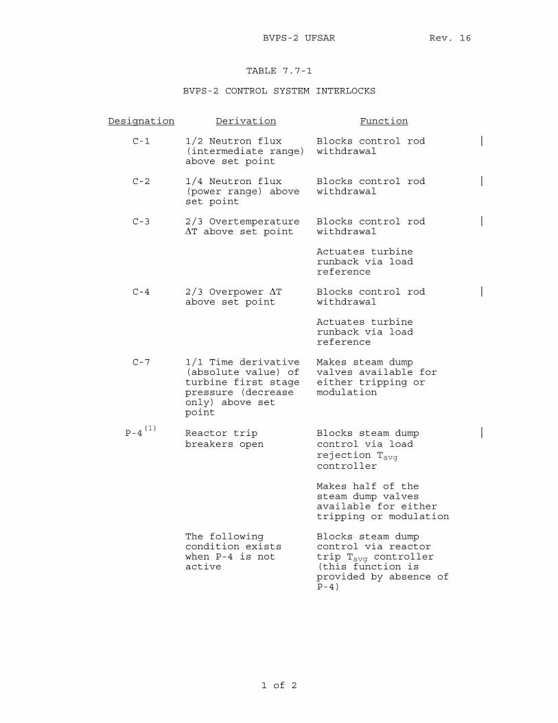
BVPS-2 UFSAR Rev. 16
1 of 2
TABLE 7.7-1
BVPS-2 CONTROL SYSTEM INTERLOCKS
Designation
Derivation
Function
C-1 1/2 Neutron flux
(intermediate range) above set point
Blocks control rod withdrawal
C-2 1/4 Neutron flux
(power range) above set point
Blocks control rod withdrawal
C-3 2/3 Overtemperature
ΔT above set point Blocks control rod withdrawal
Actuates turbine
runback via load reference
C-4 2/3 Overpower ΔT
above set point Blocks control rod withdrawal
Actuates turbine
runback via load reference
C-7 1/1 Time derivative
(absolute value) of turbine first stage pressure (decrease only) above set point
Makes steam dump valves available for either tripping or modulation
P-4
(1) Reactor trip breakers open
Blocks steam dump control via load rejection Tavg controller
Makes half of the
steam dump valves available for either tripping or modulation
The following
condition exists when P-4 is not active
Blocks steam dump control via reactor trip Tavg controller (this function is provided by absence of P-4)
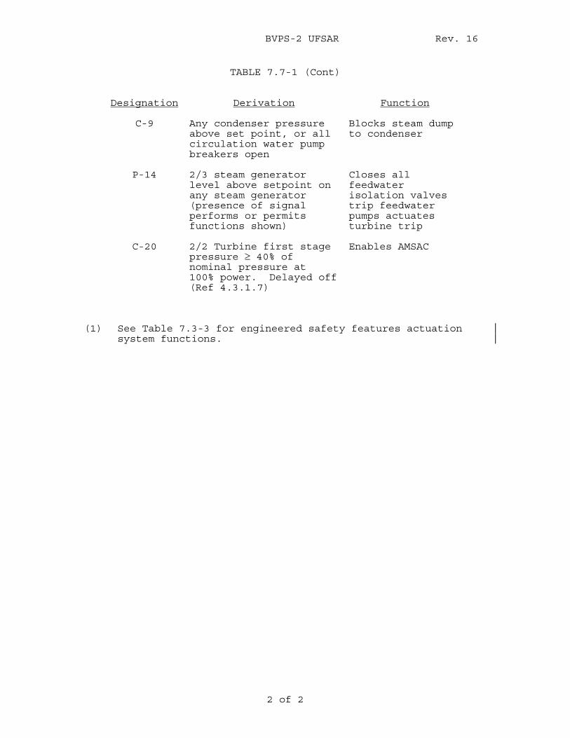
BVPS-2 UFSAR Rev. 16
2 of 2
TABLE 7.7-1 (Cont)
Designation
Derivation
Function
C-9 Any condenser pressure
above set point, or all circulation water pump breakers open
Blocks steam dump to condenser
P-14 2/3 steam generator
level above setpoint on any steam generator (presence of signal performs or permits functions shown)
Closes all feedwater isolation valves trip feedwater pumps actuates turbine trip
C-20 2/2 Turbine first stage
pressure ≥ 40% of nominal pressure at 100% power. Delayed off (Ref 4.3.1.7)
Enables AMSAC
(1) See Table 7.3-3 for engineered safety features actuation
system functions.
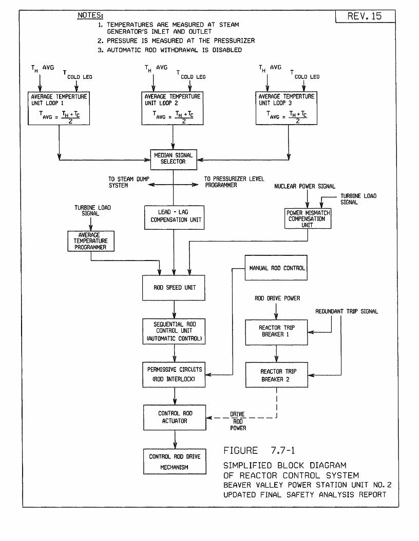
NOTES:
AVERAGE TEMPERTURE UNIT LOOP 1
TAVG = TH +Tc 2
1. TEMPERATURES ARE MEASURED AT STEAM GENERATOR'S INLET AND OUTLET
2. PRESSURE IS MEASURED AT THE PRESSURIZER 3. AUTOMATIC ROD WITHDRAWAL IS DISABLED
TH AVG T
~ CO~ LEG
AVERAGE TEMPERTURE UNIT LOOP 2
TAVG = TH + Tc 2
TH AVG T
~ CO~ LEG
AVERAGE TEMPERTURE UNIT LOOP 3
TAVG = TH + Tc 2
.... MEDIAN SIGNAL .., '-------------lrltJ!IDi SELECTOR 141t----------.~
TO STEAM DUMP SYSTEM ...,.._f-----11---~~..,.
TO PRESSURIZER LEVEL PROGRAMMER
REV D 15
TURBINE LOAD SIGNAL
NUCLEAR POWER SIGNAL . I r- TURBINE LOAD f t SIGNAL
+ AVERAGE TEMPERATURE PROGRAMMER
I
LEAD -LAG COMPENSATION UNIT
ROD SPEED UNIT
SEQUENTIAL ROD CONTROL UNIT
CAUTOMA TIC CONTROL>
POWER MISMATCH COMPENSATION
UNIT
---- MANUAL ROO CONTROL
ROD DRIVE POWER
+ REDUNDANT TRIP SIGNAL
REACTOR TRIP BREAKER 1
I
PERMISSIVE CIRCUITS ...,....,E-------J
CROD INTERLOCK) REACTOR TRIP BREAKER 2 -
CONTROL ROD ACTUATOR
CONTROL ROD DRIVE
MECHANISM
I I I
r-t __ DRIV~ ___ J ROD
POWER
FIGURE 7a7-1 SIMPLIFIED BLOCK DIAGRAM OF REACTOR CONTROL SYSTEM BEAVER VALLEY POWER STATION UNIT N0.2 UPDATED FINAL SAFETY ANALYSIS REPORT
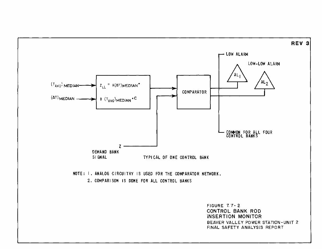
(.6.T)MEDIAN ---11"'~ ,
DEMAND BANK S I GN AL
z------
,..
"" COMPARATOR
TYPICAL OF ONE CONTROL BANK
.....-LOW ALARM
~LOW-LOW ALARM
1----'-------.11 A I
'- COMMON FOR All FOUR CONTROL BANKS
REV 3
NOTE: I • ANALOG CIRCUITRY IS US.ED FOR THE COMPARATOR NElWOR K. 2. COMPARISON IS DONE FOR ALL CONTROL BANKS
FIGURE 7. 7- 2 CONTROL BANK ROD INSERTION MONITOR BEAVER VALLEY POWER STATION -UNIT 2 FINAL SAFETY ANALYSIS REPORT
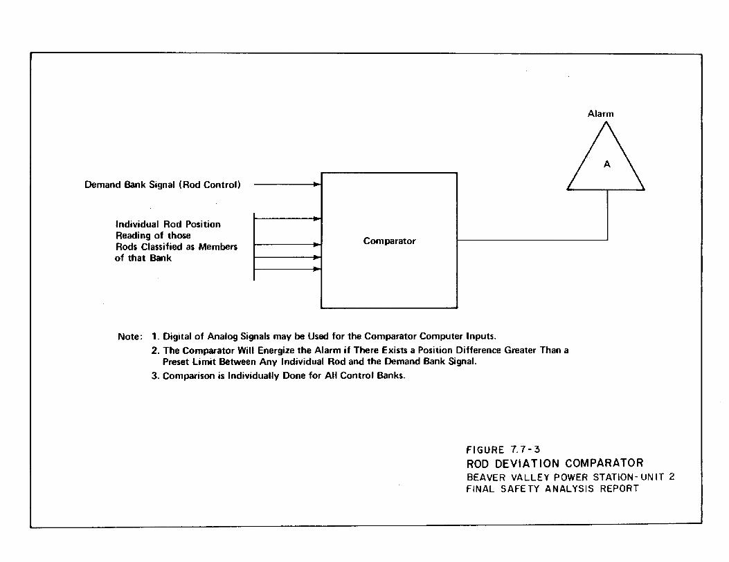
Demand Bank Signal (Rod Control)
Individual Rod Position Reading of those Rods Classified as Members of that Bank
Alarm
A
Comparator
Note: 1. Digital of Analog Signals may be Used for the Comparator Computer Inputs. 2. The Comparator Will Energize the Alarm if There Exists a Position Difference Greater Than a
Preset Limit Between Any Individual Rod and the Demand Bank Signal. 3. Comparison is Individually Done for All Control Banks.
FIGURE 7. 7-3 ROD DEVIATION COMPARATOR BEAVER VALLEY POWER STATION- UN IT 2 FINAL SAFETY ANALYSIS REPORT
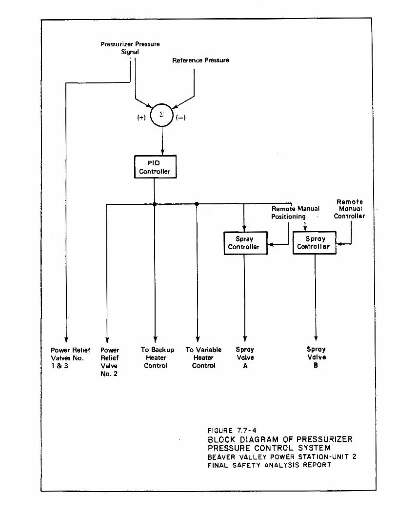
Povver Relief Valves No. 1 & 3
Pressurizer Pressure Signal
Reference Pressure
Povver Relief Valve No.2
(+)
PID Controller
It
To Backup Heater
Control
(-)
To Variable Heater Control
Spray Controller
lr
Spray Valve
A
FIGURE 7.7-4
--. Remote Manual Positioning
+ Spray
Controller
Spray Valve
8
Remote Manual
Controller
BLOCK DIAGRAM OF PRESSURIZER PRESSURE CONTROL SYSTEM BEAVER VALLEY POWER STATION-UNIT 2 FINAL SAFETY ANALYSIS REPORT
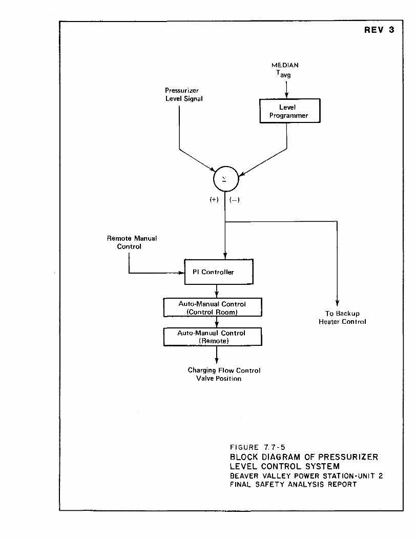
Remote Manual Control
Pressurizer Level Signal
(+) (-)
PI Controller
Auto-Manual Control (Control Room)
Auto-Manual Control (Remote)
Charging Flow Control Valve Position
ME. DIAN Tavg
Level Programmer
FIGURE 7. 7-5
REV 3
To Backup Heater Control
BLOCK DIAGRAM OF PRESSURIZER LEVEL CONTROL SYSTEM BEAVER VALLEY POWER STATION-UNIT 2 FINAL SAFETY ANALYSIS REPORT
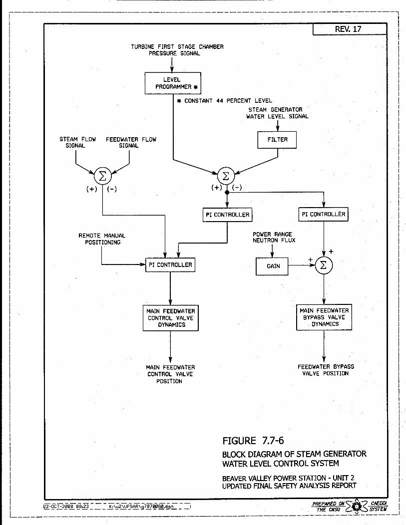
TURBINE FIRST STAGE CHAMBER PRESSURE SIGNAL
LEVEL PROGRAMMER *
* CONSTANT 44 PERCENT LEVEL STEAM GENERATOR
WATER LEVEL SIGNAL
REV. 17
STEAM FLOW FEEDWATER FLOW SIGNAL SIGNAL
(+) (-)
REMOTE MANUAL POSITIONING
MAIN FEEDWATER CONTROL VALVE
DYNAMICS
MAIN FEEDWATER CONTROL VALVE
POSITION
PI CONTROLLER
POWER RANGE NEUTRON FLUX
FIGURE 7.7-6
MAIN FEEDWATER BYPASS VALVE
DYNAMICS
FEEDWATER BYPASS VALVE POSITION
BLOCK DIAGRAM OF STEAM GENERATOR WATERLEVELCONTROLSYSTEM
BEAVER VALLEY POWER STATION - UNIT 2 UPDATED FINAL SAFETY ANALYSIS REPORT
I I I I I I I
122-0cT-200808:23--- K:\;;-2\UFSAR\_9-7070060.d-;:,~ -, PREPARED ON~i''t.? CAEDDI II --------------- ---=--- THE CNSU C::...1.,t~ SYST"EII L-----------------------------------------------------~------1
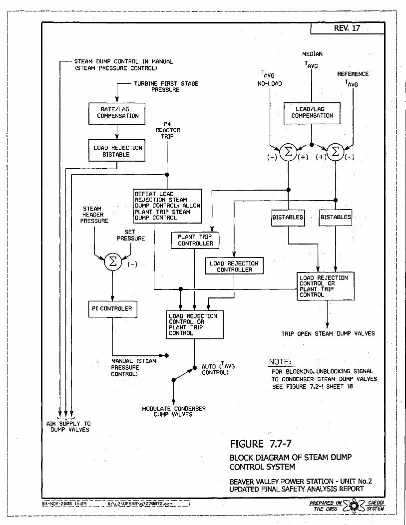
STEAM DUMP CONTROL IN MANUAL <STEAM PRESSURE CONTROL>
TURBINE FIRST STAGE PRESSURE
RATE/LAG COMPENSATION
P4 REACTOR
TRIP LOAD REJECTION
BISTABLE
STEAM HEADER
PRESSURE
DEFEAT LOAD REJECTION STEAM DUMP CONTROL: ALLOW PLANT TRIP STEAM DUMP CONTROL
SET PRESSURE PLANT TRIP
CONTROLLER
PI CONTROLER LOAD REJECTION CONTROL OR PLANT TRIP CONTROL
NO-LOAD
MEDIAN
LEAD/LAG COMPENSATION
REV. 17
REFERENCE
TRIP OPEN STEAM DUMP VALVES
MANUAL <STEAM PRESSURE CONTROL>
AUTO (T AVG CONTROL>
NOTE: FOR BLOCKING,UNBLOCKING SIGNAL TO CONDENSER STEAM DUMP VALVES SEE FIGURE 7.2-1 SHEET 10
'---v-' AIR SUPPLY TO
DUMP VALVES
MODULATE CONDENSER DUMP VALVES
FIGURE 7.7-7 BLOCK DIAGRAM OF STEAM DUMP CONTROL SYSTEM
BEAVER VALLEY POWER STATION - UNIT No.2 UPDATED FINAL SAFETY ANALYSIS REPORT
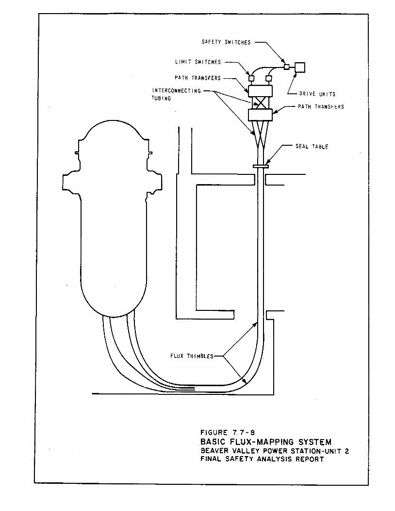
SAFETY SWITCHES
LIMIT SWITCHES
PATH TRANSFERS
INTERCONNECTING TUBING
__ ----..~1 c
FLUX THIMBLES
FIGURE 7. 7-8
PATH TRANSFERS
BASIC FLUX ... MAPPING SYSTEM BEAVER VALLEY POWER STATION-UNIT 2 FINAL SAFETY ANALYSIS REPORT
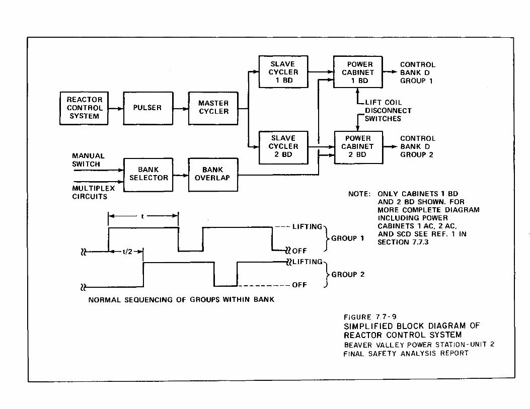
REACTOR CONTROL r-+ PULSER r--. SYSTEM
MANUAL SWITCH
BANK SELECTOR
....._... MULTIPLEX CIRCUITS
I· t
ll I. t/2_, I
ll I
r+
MASTER CYCLER ~
~
BANK OVERLAP
SLAVE CYCLER
1 BD ~
SLAVE CYCLER
2 BD ~
POWER CABINET
1 BD ~
CONTROL BANK D GROUP 1
lLIFT COl L ECT s
DISCONN rSWITCHE
POWER CABINET --+-
2 BD
CONTROL BANK D GROUP 2
NOTE: ONLY CABINETS 1 BD
L--- LIFTING} GROUP 1
lOFF
AND 2 BD SHOWN. FOR MORE COMPLETE DIAGRAM INCLUDING POWER CABINETS 1 AC, 2 AC, AND SCD SEE REF. 1 IN SECTION 7.7.3
I IILIFTING GROUP 2
L.....---J.-.-------- OFF }
NORMAL SEQUENCING OF GROUPS WITHIN BANK
FIGURE 7. 7-9 SIMPLIFIED BLOCK DIAGRAM OF REACTOR CONTROL SYSTEM BEAVER VALLEY POWER STATION-UNIT 2 FINAL SAFETY ANALYSIS REPORT
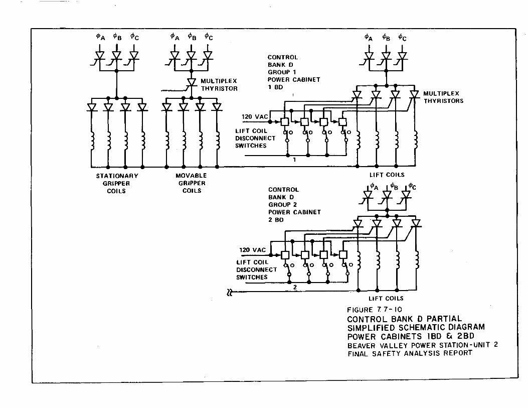
STATIONARY GRIPPER
COILS
MOVABLE GRIPPER
COILS
120 VAC
CONTROL BANK D GROUP 1 POWER CABINET 1 BD
LIFT COIL DISCONNECT SWITCHES
1
CONTROL BANK D GROUP 2 POWER CABINET 2 80
120 VAC
LIFT COIL DISCONNECT SWITCHES
LIFT COILS
MULTIPLEX THYRISTORS
z~~--------~2~--------~~~--~~ LIFT COILS
FIGURE 7 7- 10 CONTROL BANK D PARTIAL SIMPLIFIED SCHEMATIC DIAGRAM POWER CABINETS 1BD & 2BD BEAVER VALLEY POWER STATION-UNIT 2 FINAL SAFETY ANALYSIS REPORT
Related Documents