Copyright © 2001 Honeywell Inc. • All rights reserved EN0B-0319 GE51 R1001 V5422L / V5422E ACTUATED BUTTERFLY VALVES GENERAL The V5422L and V5422E Actuated Butterfly Valves are suitable for heating and cooling applications as well as in boiler management systems. They can also be employed for industrial applications, general services, water treatment, etc. The V5422L series is equipped with floating-control actuators (230 V, three-point). The V5422E series is equipped with modulating-control actuators with a standard control signal of 0...10 V (2...10 V, 0...20 mA, and 4...20 mA also possible). The actuators and valves are provided factory-mounted. The position control and the end stops are completely justified. FEATURES • With factory-mounted electric actuator • Centric butterfly valve with elastomer liner • Wide DN range (DN250 through DN600) • For heating water containing up to 50° glycol • Wafer body • For modulating and floating control • maintenance-free control drive • mechanical setting indicator • includes manual operation • ample reserve torque • sizable terminal compartment for cabling • long unit lifetime SPECIFICATIONS Valves Sizes DN250...DN600 Nominal pressure rating PN10 Shut-off pressure 10 bar Tightness bubble-tight Temperature of medium -10...+130 °C Body Wafer, ductile iron GG25 Rilsan/epoxy-coated Liner EPDM EW (max. 130 °C) Disc GGG40, epoxy-coated Shaft Stainless steel 1.4028 (AISI 420) Actuators Motor voltage 230 Vac (±10%), 50 to 60 Hz Current, running time See Table 1 Angle of rotation 90° Duty cycles max. 30% (class S4 IEC60034) Running noise 65 dBA Ambient temperature -20...+70 °C Motor insulation class F according to VDE 0530 Protection class IP67 as per DIN 40050 Cable gland PG16, cable ∅ 9...16 mm SPECIFICATION DATA

Welcome message from author
This document is posted to help you gain knowledge. Please leave a comment to let me know what you think about it! Share it to your friends and learn new things together.
Transcript

Copyright © 2001 Honeywell Inc. • All rights reserved EN0B-0319 GE51 R1001
V5422L / V5422EACTUATED BUTTERFLY VALVES
GENERALThe V5422L and V5422E Actuated Butterfly Valves aresuitable for heating and cooling applications as well as inboiler management systems. They can also be employed forindustrial applications, general services, water treatment, etc.
The V5422L series is equipped with floating-control actuators(230 V, three-point).
The V5422E series is equipped with modulating-controlactuators with a standard control signal of 0...10 V (2...10 V,0...20 mA, and 4...20 mA also possible).
The actuators and valves are provided factory-mounted. Theposition control and the end stops are completely justified.
FEATURES• With factory-mounted electric actuator• Centric butterfly valve with elastomer liner• Wide DN range (DN250 through DN600)• For heating water containing up to 50° glycol• Wafer body• For modulating and floating control• maintenance-free control drive• mechanical setting indicator• includes manual operation• ample reserve torque• sizable terminal compartment for cabling• long unit lifetime
SPECIFICATIONSValvesSizes DN250...DN600Nominal pressure rating PN10Shut-off pressure 10 barTightness bubble-tightTemperature of medium -10...+130 °CBody Wafer, ductile iron GG25
Rilsan/epoxy-coatedLiner EPDM EW (max. 130 °C)Disc GGG40, epoxy-coatedShaft Stainless steel 1.4028 (AISI 420)
ActuatorsMotor voltage 230 Vac (±10%), 50 to 60 HzCurrent, running time See Table 1Angle of rotation 90°Duty cycles max. 30% (class S4 IEC60034)Running noise 65 dBAAmbient temperature -20...+70 °CMotor insulation class F according to VDE 0530Protection class IP67 as per DIN 40050Cable gland PG16, cable ∅ 9...16 mm
SPECIFICATION DATA
V5422L / V5422E ACTUATED BUTTERFLY VALVES
EN0B-0319 GE51 R1001 2
Table 1. Type list for different valve sizes and corresponding dataActuator current (A)Floating
versionModulating
version Nominal StartRun time
(sec)Actuator
torque (Nm)Valve size
(DN)Kvs
(m3/h)Weight
(kg)V5422L1006 V5422E1001 1.2 1.7 30 600 250 4800 39.2V5422L1014 V5422E1019 1.2 1.7 30 600 300 7000 48V5422L1022 V5422E1027 2.0 3.0 30 800 350 8300 60V5422L1030 V5422E1035 1.2 1.7 60 1200 400 11000 87V5422L1048 V5422E1043 2.5 3.5 60 1500 450 14000 127V5422L1055 V5422E1050 2.5 3.5 105 2500 500 18000 193V5422L1063 V5422E1068 2.5 3.5 120 4000 600 25000 250
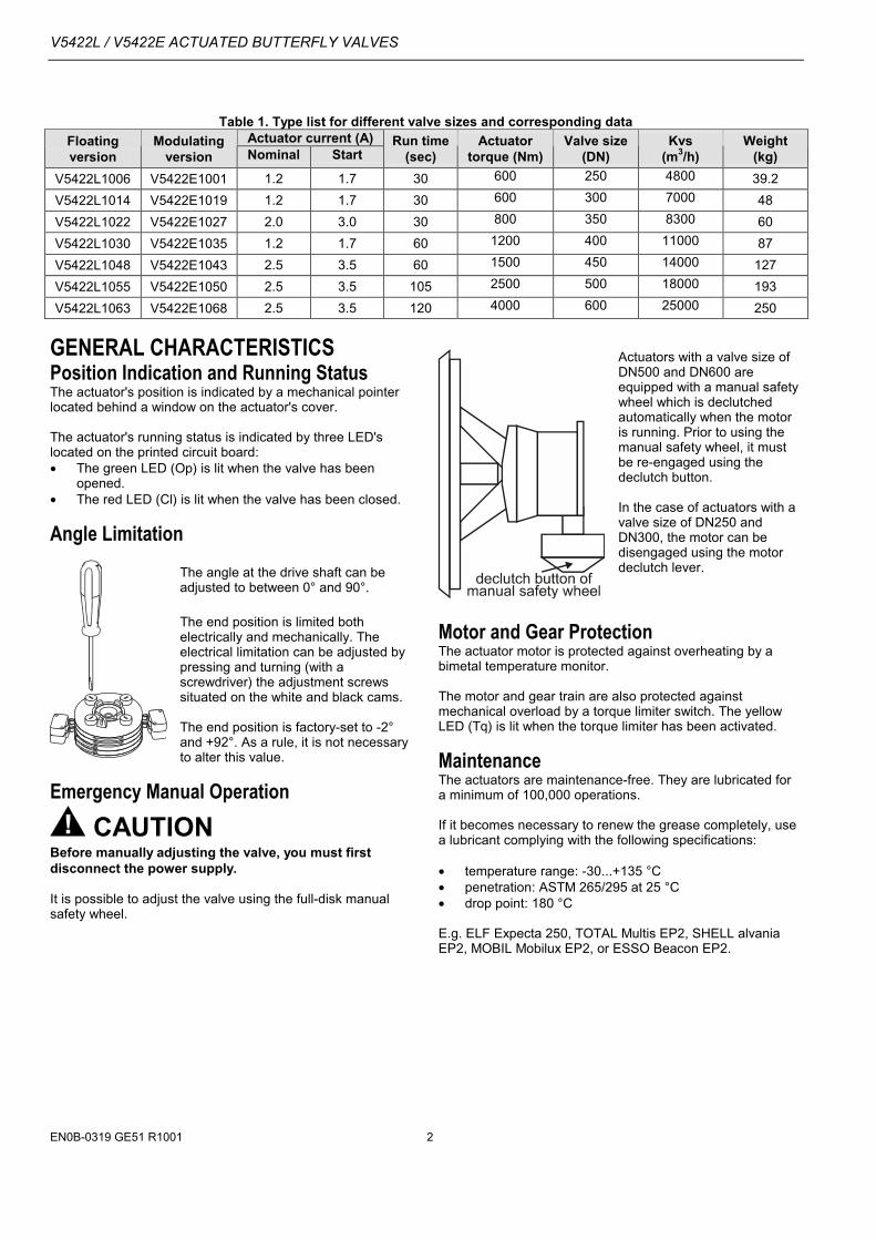
GENERAL CHARACTERISTICSPosition Indication and Running StatusThe actuator's position is indicated by a mechanical pointerlocated behind a window on the actuator's cover.
The actuator's running status is indicated by three LED'slocated on the printed circuit board:• The green LED (Op) is lit when the valve has been
opened.• The red LED (Cl) is lit when the valve has been closed.
Angle LimitationThe angle at the drive shaft can beadjusted to between 0° and 90°.
The end position is limited bothelectrically and mechanically. Theelectrical limitation can be adjusted bypressing and turning (with ascrewdriver) the adjustment screwssituated on the white and black cams.
The end position is factory-set to -2°and +92°. As a rule, it is not necessaryto alter this value.
Emergency Manual Operation
CAUTIONBefore manually adjusting the valve, you must firstdisconnect the power supply.
It is possible to adjust the valve using the full-disk manualsafety wheel.
Actuators with a valve size ofDN500 and DN600 areequipped with a manual safetywheel which is declutchedautomatically when the motoris running. Prior to using themanual safety wheel, it mustbe re-engaged using thedeclutch button.
In the case of actuators with avalve size of DN250 andDN300, the motor can bedisengaged using the motordeclutch lever.
Motor and Gear ProtectionThe actuator motor is protected against overheating by abimetal temperature monitor.
The motor and gear train are also protected againstmechanical overload by a torque limiter switch. The yellowLED (Tq) is lit when the torque limiter has been activated.
MaintenanceThe actuators are maintenance-free. They are lubricated fora minimum of 100,000 operations.
If it becomes necessary to renew the grease completely, usea lubricant complying with the following specifications:
• temperature range: -30...+135 °C• penetration: ASTM 265/295 at 25 °C• drop point: 180 °C
E.g. ELF Expecta 250, TOTAL Multis EP2, SHELL alvaniaEP2, MOBIL Mobilux EP2, or ESSO Beacon EP2.
V5422L / V5422E ACTUATED BUTTERFLY VALVES
EN0B-0319 GE51 R10013
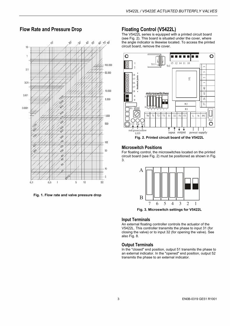
Flow Rate and Pressure Drop
Fig. 1. Flow rate and valve pressure drop
Floating Control (V5422L)The V5422L series is equipped with a printed circuit board(see Fig. 2). This board is situated under the cover, wherethe angle indicator is likewise located. To access the printedcircuit board, remove the cover.
Fig. 2. Printed circuit board of the V5422L
Microswitch PositionsFor floating control, the microswitches located on the printedcircuit board (see Fig. 2) must be positioned as shown in Fig.3.
Fig. 3. Microswitch settings for V5422L
Input TerminalsAn external floating controller controls the actuator of theV5422L. This controller transmits the phase to input 31 (forclosing the valve) or to input 32 (for opening the valve). Seealso Fig. 8.
Output TerminalsIn the "closed" end position, output 51 transmits the phase toan external indicator. In the "opened" end position, output 52transmits the phase to an external indicator.

V5422L / V5422E ACTUATED BUTTERFLY VALVES
EN0B-0319 GE51 R1001 4
Modulating Control (V5422E)The V5422E series is equipped with a printed circuit board(see Fig. 4). This board (together with a feedback potentio-meter) is situated under the cover, where the angle indicatoris likewise located. To access the printed circuit board,remove the cover.
Fig. 4. Printed circuit board of the V5422E
Microswitch PositionsFig. 5 shows the settings of the microswitches located on theprinted circuit board (see Fig. 4) at delivery-time.
Fig. 5. Microswitch settings for the V5422E at delivery
Microswitches 1, 2, 3, and 4 are used to set the input signalrange (0/2...10 V or 0/4...20 mA) and the correspondingoutput signal (see Table 2).
Table 2. Resetting Microswitchesinput/output
signal Microswitch positions
7 6 5 4 3 2 10...10 V A A A B B B B2...10 V A A A A B B B
4...20 mA A A A A A A A0...20 mA A A A B A A A
Terminals for Input/Output SignalsAn external modulating controller controls the actuator of theV5422E by means of an analog signal provided at terminal70/71. An analog output signal for position indication isprovided at terminal 71/72.
Adjusting the Input/Output Signal OffsetThe offset of modulating actuators is adjusted at the factoryand should not be changed. If you wish to change the offset(using offset potentiometer P2; see Fig. 4), note that aexcessively small offset will result in oscillation of theactuator.
Reversing Rotation DirectionIn the case of the V5422E, it is possible to reverse thedirection of rotation of the valve by adjusting the feedbacksignals. The feedback signals are adjusted by resetting themicroswitches and replugging the feedback potentiometer'scables. To do this, proceed as follows:
1. Turn the power off.2. Reset the microswitches as shown in Table 2, but with
microswitch 7 in position B.3. Replug the feedback potentiometer's cables as shown in
Fig. 6.
Fig. 6. Replugging the feedback potentiometer's cables
4. Apply the desired control signal (10 V or 20 mA, as thecase may be) for the closing position.
5. Turn the power back on.6. Using a small screwdriver, adjust the potentiometer P1
(located on the printed circuit board; see Fig. 4) until thevalve closes completely.
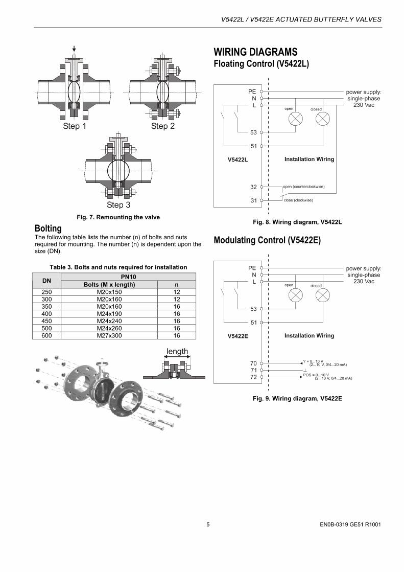
Valve MountingInstall the actuated valve in the pipe according the followingsteps (see also Fig. 7).
1. Spread the valve's flanges to facilitate installation. Thevalve's disc must be partially open.
2. Set all stay-bolts while keeping the valve's disc slightlyopen and without tightening the nuts.
3. Open the valve's disc completely. Ensure that the pipingis aligned. Tighten diagonally opposite the nuts until theflanges are in contact with the body of the valve. Neveruse gaskets or grease. Never weld the flanges after thevalve has been installed.
V5422L / V5422E ACTUATED BUTTERFLY VALVES
EN0B-0319 GE51 R10015
Fig. 7. Remounting the valve
BoltingThe following table lists the number (n) of bolts and nutsrequired for mounting. The number (n) is dependent upon thesize (DN).
Table 3. Bolts and nuts required for installationPN10DN Bolts (M x length) n
250 M20x150 12300 M20x160 12350 M20x160 16400 M24x190 16450 M24x240 16500 M24x260 16600 M27x300 16
WIRING DIAGRAMSFloating Control (V5422L)
Fig. 8. Wiring diagram, V5422L
Modulating Control (V5422E)
Fig. 9. Wiring diagram, V5422E

V5422L / V5422E ACTUATED BUTTERFLY VALVES
Home and Building ControlHoneywell AGBöblinger Straβe 17D-71101 SchönaichPhone: (49) 7031 63701Fax: (49) 7031 637493http://europe.hbc.honeywell.com
Subject to change without notice. Printed in Germany Manufacturing location certified to
EN0B-0319 GE51R1001
ACTUATED VALVE DIMENSIONS
Fig. 10. Actuated butterfly valve (side view)
Fig. 11. Actuated butterfly valve (top view)
Fig. 12. Actuated butterfly valve (cross-sectional view)
Table 4. Actuator dimensions and weightActuator dimensions (mm)Valve
size (DN) A B C D EWeight
(kg)250 509 169 315 89 177 17300 509 169 315 89 177 17350 509 169 315 89 177 17400 564 172 417 133 167 30450 564 172 417 133 167 30500 754 566 442 109 281 68600 645 497 442 154 28 70
Table 5. Valve dimensions and weightValve dimensions (mm)Valve
size (DN) A B C D HWeight
(kg)250 280 196 68 324 243.5 22.2300 315 232 78 378 292.5 30.8350 330 257 78 425 329.5 41.5400 365 292 102 475 375.5 57.2450 400 359 114 ^538 426 95.0500 440 397 127 595 577 125600 525 467 154 695 572 180
SPARE PARTSTable 6. Spare parts (available, upon request)
Order No.Valve size (DN) Packing ring O-ring Nitrile250 LI-DE 0250 EW SP-DE 0250300 LI-DE 0300 EW SP-DE 0300350 LI-DE 0350 EW SP-DE 0350400 LI-DE 0400 EW SP-DE 0400450 LI-DE 0450 EW SP-DE 0450500 LI-DE 0500 EW SP-DE 0500600 LI-DE 0600 EW SP-DE 0600
Related Documents