BUILDING SERVICES 451 S. State Room 215 Salt Lake City, Utah 84114 (M,T, TH, F 7:30am - 4:30pm W 9:00am-4:30pm) (801) 535-6000 www.slcpermits.com Project Information Contact Name Date BLD # Phone Total Valuation Electrical Valuation E-mail Permit Type Commercial Residential Site Address: Comments: State License # Size of System (kW): Mounted To: Roof Ground Located on: Primary Structure Accessory Structure Type Of System: A/C Module Micro-Inverter Standard String Required Information Site plan showing location of major components on the property. This drawing need not be exactly to scale, but it should represent relative location of components at site (see supplied example site plan). Electrical diagram showing PV array configuration, wiring system, over current protection, inverter, disconnects, required labels, and A/C connection to building. See supplied standard electrical diagram on Page 7 of this application. This permit becomes null and void if work or construction authorized is not commenced within 180 days, or if construction or work is suspended or abandoned for a period of 180 days at any time after work is commenced. I hereby certify that I have read and examined this application and know the same to be true and correct. All provisions of laws and ordinances governing this type of work will be complied with whether specified herein or not. The granting of a permit does not presume to give authority to violate or cancel the provisions of any other state or local law regulating construction and that I make this statement under penalty of perjury. Signature & Date: Owner Contractor Other:________________ SOLAR PV PERMIT PROCESS 1 of 7

Welcome message from author
This document is posted to help you gain knowledge. Please leave a comment to let me know what you think about it! Share it to your friends and learn new things together.
Transcript

BUILDING SERVICES 451 S. State Room 215 Salt Lake City, Utah 84114 (M,T, TH, F 7:30am - 4:30pmW 9:00am-4:30pm) (801) 535-6000
www.slcpermits.com
Project InformationContact Name Date BLD #
Phone
Total Valuation
Electrical Valuation
Permit Type Commercial Residential
Site Address:
Comments:
State License #
Size of System (kW):
Mounted To:
Roof
Ground
Located on:
Primary Structure
Accessory Structure
Type Of System:
A/C Module
Micro-Inverter
Standard String
Required Information
Site plan showing location of major components on the property. This drawing need not be exactly to scale, but it should represent relative location of components at site (see supplied example site plan).
Electrical diagram showing PV array configuration, wiring system, over current protection, inverter, disconnects, required labels, and A/C connection to building. See supplied standard electrical diagram on Page 7 of this application.
This permit becomes null and void if work or construction authorized is not commenced within 180 days, or if construction or work is suspended or abandoned for a period of 180 days at any time after work is commenced. I hereby certify that I have read and examined this application and know the same to be true and correct. All provisions of laws and ordinances governing this type of work will be complied with whether specified herein or not. The granting of a permit does not presume to give authority to violate or cancel the provisions of any other state or local law regulating construction and that I make this statement under penalty of perjury.
Signature & Date: Owner Contractor Other:________________
SOLAR PV PERMIT PROCESS
1 of 7
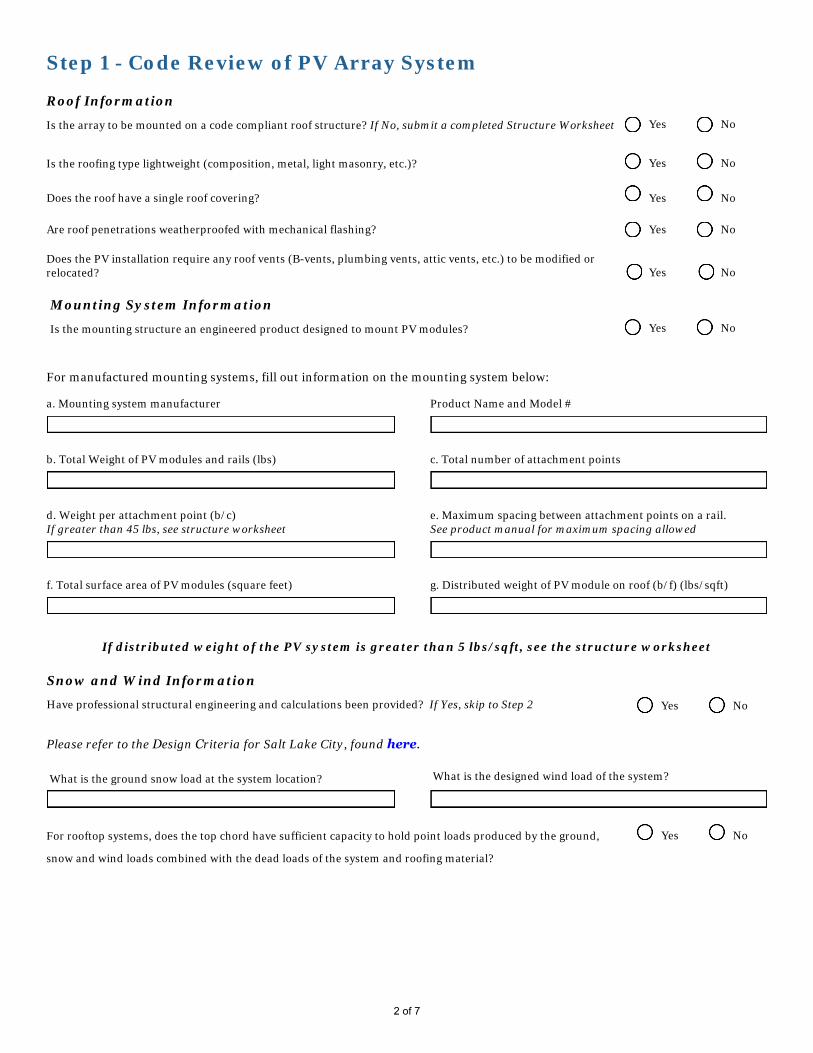
Step 1 - Code Review of PV Array System
Roof Information
Is the array to be mounted on a code compliant roof structure? If No, submit a completed Structure Worksheet Yes No
Is the roofing type lightweight (composition, metal, light masonry, etc.)? Yes No
Does the roof have a single roof covering? Yes No
Are roof penetrations weatherproofed with mechanical flashing? Yes No
Does the PV installation require any roof vents (B-vents, plumbing vents, attic vents, etc.) to be modified or relocated? Yes No
Mounting System Information
Is the mounting structure an engineered product designed to mount PV modules? Yes No
For manufactured mounting systems, fill out information on the mounting system below:
a. Mounting system manufacturer Product Name and Model #
b. Total Weight of PV modules and rails (lbs) c. Total number of attachment points
d. Weight per attachment point (b/c)If greater than 45 lbs, see structure worksheet
e. Maximum spacing between attachment points on a rail.See product manual for maximum spacing allowed
f. Total surface area of PV modules (square feet) g. Distributed weight of PV module on roof (b/f) (lbs/sqft)
If distributed weight of the PV system is greater than 5 lbs/sqft, see the structure worksheet
Snow and Wind Information
Have professional structural engineering and calculations been provided? If Yes, skip to Step 2 Yes No
Please refer to the Design Criteria for Salt Lake City, found here.
What is the ground snow load at the system location? What is the designed wind load of the system?
NoFor rooftop systems, does the top chord have sufficient capacity to hold point loads produced by the ground, Yes
snow and wind loads combined with the dead loads of the system and roofing material?
2 of 7

Structure Worksheet
If array is roof mounted:
This section is for evaluating roof structural members that are site built. This includes rafter systems and site built trusses. Manufactured truss and roof joist systems, when installed with proper spacing, meet the roof structure requirements covered in item 2 below.
Roof Construction
Rafters
Trusses
Other
Describe site-built rafter or site-built truss system:
Rafter Size: Inches X Inches
Rafter spacing: Inches
Maximum unsupported span: Feet, inches
Are the rafters over-spanned? If Yes, complete the rest of this section
Yes No
If the roof system has a. Over-spanned rafters or trussesb. The array is over 5 lbs/sqft on any roof construction, orc. The attachments with a dead load exceeds 45 lbs per attachment, ord. Excess capacity after the sum of dead loads, with snow and wind loads is less than IRC requirements for live loads;
Please provide one of the following: i. A framing plan that shows details for how you will strengthen the rafters,
ii. Confirmation certified by a design professional that the existing roof structure will support the array
If array is ground mounted:
Show array supports, framing members, foundation posts, and footings,
Provide information on mounting structure(s) construction. If the mounting structure is unfamiliar to the local jurisdiction and is more than six (6) feet above grade, it may require engineering calculations certified by a design professional.
Show detail on module attachment method to mounting structure.
3 of 7
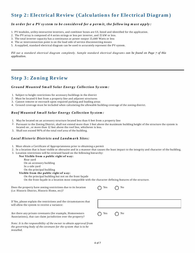
Step 2: Electrical Review (Calculations for Electrical Diagram)
In order for a PV system to be considered for a permit, the following must apply:
1. PV modules, utility-interactive inverters, and combiner boxes are UL listed and identified for the application.2. The PV array is composed of 4 series strings or less per inverter, and 15 kW or less.3. The total inverter capacity has a continuous ac power output 13,440 Watts or less4. The ac interconnection point is on the load side of service disconnecting means5. A supplied, standard electrical diagram can be used to accurately represent the PV system.
Step 3: Zoning Review
Ground Mounted Small Solar Energy Collection System:
1. Subject to height restrictions for accessory buildings in the district2. Must be located 6 feet from a property line and adjacent structures3. Cannot remove or encroach upon required parking and loading areas4. Ground coverage must be included when calculating the allowable building coverage of the zoning district.
Roof Mounted Small Solar Energy Collection System:
1. May be located on an accessory structure located less than 6 feet from a property line2. Pursuant to the Zoning District, shall not extend more than 3 feet above the maximum building height of the structure the system is
located on , or more than 12 feet above the roof line, whichever is less.3. Shall not exceed 90% of the total roof area of the building.
Local Historic Districts and Landmark Sites:
1. Must obtain a Certificate of Appropriateness prior to obtaining a permit2. In a location that is least visible or obtrusive and in a manner that causes the least impact to the integrity and character of the building.3. Location restrictions will be reviewed based on the following hierarchy:
Not Visible from a public right of way: Rear yard On an accessory building In a side yard On the principal building
Visible from the public right of way: On the principal building but not on the front façade On the front façade in a location most compatible with the character defining features of the structure.
Does the property have zoning restrictions due to its location (i.e: Historic District, Historic Home, etc)?
Yes No
If Yes, please explain the restrictions and the circumstances that will allow the system to receive a variance:
Are there any private covenants (for example, Homeowners Associations), that can claim jurisdiction over the property?
Note: It is the responsibility of the owner to obtain approval from the governing body of the covenant for the system that is to be installed.
Yes No
4 of 7
Fill out a standard electrical diagram completely. Sample standard electrical diagrams can be found on Page 7 of this application.

Step 4: Fire Review
In order for a PV system to be considered for a permit, the following must apply:
Does the provided Site Plan show a clearly dimensioned pathway and a clearly dimensioned access path to and around the panels? Fire Code requires a minimum of 3' to ridge and along one side for access.
The Fire Code Official must be able to determine that a rational approach has been used and any reductions in clear area from those required by code are warranted.
Yes No
Are all system disconnects located in the same location as the utility disconnects?
Yes No
Do you agree to provide weather resistant, permanently affixed labels to all equipment, conduits, raceways, and junction boxes every 10 feet?
Yes No
Do you agree to provide clearly labeled metal conduits, or MC cable until the first readily accessible disconnect is reached, when conduits containing DC current conductors are under the roof deck or in the attic space?
Yes No
All metal parts of all modules, modules supports, system equipment, and conductor enclosures shall be bonded together and connected to the grounding system. The bonding shall also be to the electrical utility.
Do you agree to provide? Yes No
Bipolar source and output circuit equipment shall be labeled as follows: "Warning: Bipolar Photovoltaic Array. Disconnection of neutral or grounded conductors may result in overvoltage on array inverter"
Do you agree to provide? Yes No
For Standard String Systems only:
Disconnection of photovoltaic equipment shall be labeled as follows: "Warning: ELECTRIC SHOCK HAZZARD. Do not touch terminals. Terminals on both the line and load sides may be energized in the open position."
Do you agree to provide? Yes No N/A
Underground photovoltaic power systems shall be labeled as follows: "Warning: ELECTRIC SHOCK HAZZARD. The DC conductors of this photovoltaic system are underground and may be energized." Do you agree to provide?
Do you agree to provide? Yes No N/A
5 of 7

SITE PlAN
SAM
PLE
EXAMPLE
6 of 7
Exped
ited Per
mit Pr
oc
ess for
PV
Systems
5
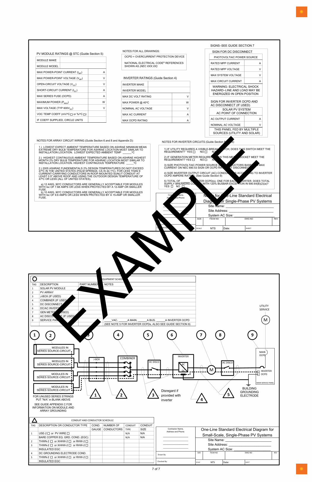
Notes for Standard String System Electrical Diagram
Contractor Name,Address and Phone:
____________________________________________________________________
Notes for One-Line Standard ElectricalDiagram for Single-Phase PV Systems
Site Name: __________________________Site Address: ________________________System AC Size: ______________________
SIZE FSCM NO DWG NO REV
SCALE NTS Date: SHEET
Drawn By:
Checked By:
MAX POWER-POINT CURRENT (IMP)
MAX POWER-POINT VOLTAGE (VMP)
OPEN-CIRCUIT VOLTAGE (VOC)
SHORT-CIRCUIT CURRENT (ISC)
MAX SERIES FUSE (OCPD)
MAXIMUM POWER (PMAX)
MAX VOLTAGE (TYP 600VDC)
VOC TEMP COEFF (mV/oC or %/oC )
IF COEFF SUPPLIED, CIRCLE UNITS
A
V
V
A
A
W
V
MODULE MAKE
MODULE MODEL
PV MODULE RATINGS @ STC (Guide Section 5)
MAX DC VOLT RATING
MAX POWER @ 40oC
NOMINAL AC VOLTAGE
MAX AC CURRENT
MAX OCPD RATING
V
W
V
A
A
INVERTER MAKE
INVERTER MODEL
INVERTER RATINGS (Guide Section 4)
1) IF UTILITY REQUIRES A VISIBLE-BREAK SWITCH, DOES THIS SWITCH MEET THEREQUIREMENT? YES NO N/A
2) IF GENERATION METER REQUIRED, DOES THIS METER SOCKET MEET THEREQUIREMENT? YES NO N/A
3) SIZE PHOTOVOLTAIC POWER SOURCE (DC) CONDUCTORS BASED ON MAXCURRENT ON NEC 690.53 SIGN OR OCPD RATING AT DISCONNECT
4) SIZE INVERTER OUTPUT CIRCUIT (AC) CONDUCTORS ACCORDING TO INVERTEROCPD AMPERE RATING. (See Guide Section 9)
5) TOTAL OF ______ INVERTER OCPD(s), ONE FOR EACH INVERTER. DOES TOTALSUPPLY BREAKERS COMPLY WITH 120% BUSBAR EXCEPTION IN 690.64(B)(2)(a)?YES NO
NOTES FOR INVERTER CIRCUITS (Guide Section 8 and 9):
1.) LOWEST EXPECT AMBIENT TEMPERATURE BASED ON ASHRAE MINIMUM MEANEXTREME DRY BULB TEMPERATURE FOR ASHRAE LOCATION MOST SIMILAR TOINSTALLATION LOCATION. LOWEST EXPECTED AMBIENT TEMP ______oC
2.) HIGHEST CONTINUOUS AMBIENT TEMPERATURE BASED ON ASHRAE HIGHESTMONTH 2% DRY BULB TEMPERATURE FOR ASHRAE LOCATION MOST SIMILAR TOINSTALLATION LOCATION. HIGHEST CONTINUOUS TEMPERATURE _____oC
2.) 2005 ASHRAE FUNDEMENTALS 2% DESIGN TEMPERATURES DO NOT EXCEED47oC IN THE UNITED STATES (PALM SPRINGS, CA IS 44.1oC). FOR LESS THAN 9CURRENT-CARRYING CONDUCTORS IN ROOF-MOUNTED SUNLIT CONDUIT ATLEAST 0.5" ABOVE ROOF AND USING THE OUTDOOR DESIGN TEMPERATURE OF47oC OR LESS (ALL OF UNITED STATES),
a) 12 AWG, 90oC CONDUCTORS ARE GENERALLY ACCEPTABLE FOR MODULESWITH Isc OF 7.68 AMPS OR LESS WHEN PROTECTED BY A 12-AMP OR SMALLERFUSE.
b) 10 AWG, 90oC CONDUCTORS ARE GENERALLY ACCEPTABLE FOR MODULESWITH Isc OF 9.6 AMPS OR LESS WHEN PROTECTED BY A 15-AMP OR SMALLERFUSE.
NOTES FOR ARRAY CIRCUIT WIRING (Guide Section 6 and 8 and Appendix D):
OCPD = OVERCURRENT PROTECTION DEVICE
NATIONAL ELECTRICAL CODE® REFERENCESSHOWN AS (NEC XXX.XX)
NOTES FOR ALL DRAWINGS:
SIGNS–SEE GUIDE SECTION 7
SIGN FOR DC DISCONNECT
SIGN FOR INVERTER OCPD ANDAC DISCONNECT (IF USED)
RATED MPP CURRENT
RATED MPP VOLTAGE
MAX SYSTEM VOLTAGE
MAX CIRCUIT CURRENT
A
V
V
A
PHOTOVOLTAIC POWER SOURCE
WARNING: ELECTRICAL SHOCKHAZARD–LINE AND LOAD MAY BEENERGIZED IN OPEN POSITION
AC OUTPUT CURRENT
NOMINAL AC VOLTAGE
A
V
SOLAR PV SYSTEMAC POINT OF CONNECTION
THIS PANEL FED BY MULTIPLESOURCES (UTILITY AND SOLAR)
Exp
edit
ed P
erm
it P
ro
ces
s fo
r P
V S
yste
ms
4
Standard String System Electrical Diagram
EXAMPLE
7 of 7
RD7548
Typewritten Text
RD7548
Typewritten Text
RD7548
Typewritten Text
RD7548
Typewritten Text
RD7548
Typewritten Text
RD7548
Typewritten Text
RD7548
Typewritten Text
RD7548
Typewritten Text
RD7548
Typewritten Text
RD7548
Typewritten Text
STANDARD STRING SYSTEM ELECTRICAL DIAGRAM
RD7548
Typewritten Text
RD7548
Typewritten Text
RD7548
Typewritten Text
NOTE FOR STANDARD STRING SYSTEM ELECTRICAL DIAGRAM
RD7548
Typewritten Text
RD7548
Typewritten Text
RD7548
Typewritten Text
RD7548
Typewritten Text
RD7548
Typewritten Text
RD7548
Typewritten Text
RD7548
Typewritten Text
RD7548
Typewritten Text
RD7548
Typewritten Text
RD7548
Typewritten Text
RD7548
Typewritten Text
RD7548
Typewritten Text
RD7548
Typewritten Text
RD7548
Typewritten Text
RD7548
Typewritten Text
RD7548
Typewritten Text
RD7548
Typewritten Text
RD7548
Typewritten Text
RD7548
Typewritten Text
RD7548
Typewritten Text
RD7548
Typewritten Text
RD7548
Typewritten Text
Related Documents