Broadband volume holographic imaging Arnab Sinha and George Barbastathis We demonstrate transmission geometry volume holograms working under broadband illumination. We show that increased illumination bandwidth enhances the lateral field of view of planar reference holograms. We exploit this phenomenon to design volume holographic spectrum analyzers and present results from an experimental prototype. Furthermore, we show that there is a trade-off involved, because an improvement in the field of view results in a reduction of image contrast as a function of depth. We experimentally demonstrate this trade-off and discuss possible ways to overcome it. © 2004 Optical Society of America OCIS codes: 090.7330, 110.0110, 110.6770. 1. Introduction Volume holographic imaging VHI is a recent imaging technique 1 that exploits the Bragg selectivity 2,3 of volu- metric diffraction gratings 4 to optically slice the object space of the imaging system. VHI systems have been used in several applications: a confocal microscope with the volume hologram replacing the pinhole, 5 a real-time scan-free four-dimensional hyperspectral microscope, 6 and a long-range surface profilometer. 7,8 VHI systems have particularly simple recording geom- etries. We have previously investigated 9 VHI sys- tems that were recorded with a spherical reference and a planar signal beam and also VHI systems that were recorded with planar reference PR and signal beams. We have shown that, under monochromatic illumina- tion, the depth resolution for VHI exhibits a quadratic dependence on the object distance. Appropriately de- signed objective optics can optimize the resolution for a particular distance. Liu et al. 6 demonstrated a fluorescent broadband VHI system that could acquire hyperspectral data in real time. The authors took advantage of the shift 10,11 and angular 2 selectivity of volume holograms to record gratings corresponding to different depths in the object space. The fluorescent probes illuminated a slit in each of these depths because of the wavelength selectivity. 12 The gratings were recorded such that the diffracted beam from each grating focused on dif- ferent parts on the CCD camera. To our knowledge, this was the first demonstration of a real-time hyper- spectral microscope. Here we present a detailed anal- ysis of broadband VHI and new theoretical and experimental results relating the depth contrast to the illumination bandwidth of this system. This paper is arranged as follows: In Section 2 we derive and verify the properties of the diffracted field under multicolor readout and illustrate how this can be used to design volume holographic spectrum ana- lyzers. In Section 3 we examine the operation of a volume holographic spectrometer. In Section 4 we show both theoretically and experimentally that the improved field of view FOV that is due to broadband illumination results in a trade-off in terms of a degra- dation of the depth resolution of the imaging system. In Section 5 we initiate some preliminary discussion about possible methods to offset the resolution degra- dation and conclude with some directions for future research. 2. Properties of the Diffracted Field in Planar Reference Volume Holographic Imaging under Multicolor Readout Figure 1a is a schematic that shows the recording procedure for PR VHI. The volume hologram is the three-dimensional 3-D interference pattern of two mutually coherent planar beams; a normally incident reference beam and a signal beam are inclined at an angle s 1 rad with respect to the z ˆ axis. The recording wavelength is f . All angles and wave- lengths are measured inside the volume hologram that is assumed to have a refractive index n and is L units thick. The reference beam E f r can be written as E f r exp i 2 z f . (1) The authors are with the Department of Mechanical Engineer- ing, Massachusetts Institute of Technology, Room 3-466, 77 Mas- sachusetts Avenue, Cambridge, Massachusetts 021239. The e-mail address for A. Sinha is [email protected]. Received 15 December 2003; revised manuscript received 29 May 2004; accepted 2 July 2004. 0003-693504275214-08$15.000 © 2004 Optical Society of America 5214 APPLIED OPTICS Vol. 43, No. 27 20 September 2004

Welcome message from author
This document is posted to help you gain knowledge. Please leave a comment to let me know what you think about it! Share it to your friends and learn new things together.
Transcript
B
A
1
VtmsuwrmVetarWtdsp
Vrsttast
ise
M
5
roadband volume holographic imaging
rnab Sinha and George Barbastathis
We demonstrate transmission geometry volume holograms working under broadband illumination. Weshow that increased illumination bandwidth enhances the lateral field of view of planar referenceholograms. We exploit this phenomenon to design volume holographic spectrum analyzers and presentresults from an experimental prototype. Furthermore, we show that there is a trade-off involved,because an improvement in the field of view results in a reduction of image contrast as a function of depth.We experimentally demonstrate this trade-off and discuss possible ways to overcome it. © 2004 OpticalSociety of America
OCIS codes: 090.7330, 110.0110, 110.6770.
ftsyei
dublvsiidIadr
2RM
Fptmrarlit
. Introduction
olume holographic imaging �VHI� is a recent imagingechnique1 that exploits the Bragg selectivity2,3 of volu-etric diffraction gratings4 to optically slice the object
pace of the imaging system. VHI systems have beensed in several applications: a confocal microscopeith the volume hologram replacing the pinhole,5 a
eal-time �scan-free� four-dimensional hyperspectralicroscope,6 and a long-range surface profilometer.7,8
HI systems have particularly simple recording geom-tries. We have previously investigated9 VHI sys-ems that were recorded with a spherical reference andplanar signal beam and also VHI systems that were
ecorded with planar reference �PR� and signal beams.e have shown that, under monochromatic illumina-
ion, the depth resolution for VHI exhibits a quadraticependence on the object distance. Appropriately de-igned objective optics can optimize the resolution for aarticular distance.Liu et al.6 demonstrated a fluorescent broadband
HI system that could acquire hyperspectral data ineal time. The authors took advantage of thehift10,11 and angular2 selectivity of volume hologramso record gratings corresponding to different depths inhe object space. The fluorescent probes illuminatedslit in each of these depths because of the wavelength
electivity.12 The gratings were recorded such thathe diffracted beam from each grating focused on dif-
The authors are with the Department of Mechanical Engineer-ng, Massachusetts Institute of Technology, Room 3-466, 77 Mas-achusetts Avenue, Cambridge, Massachusetts 021239. The-mail address for A. Sinha is [email protected] 15 December 2003; revised manuscript received 29ay 2004; accepted 2 July 2004.0003-6935�04�275214-08$15.00�0© 2004 Optical Society of America
214 APPLIED OPTICS � Vol. 43, No. 27 � 20 September 2004
erent parts on the CCD camera. To our knowledge,his was the first demonstration of a real-time hyper-pectral microscope. Here we present a detailed anal-sis of broadband VHI and new theoretical andxperimental results relating the depth contrast to thellumination bandwidth of this system.
This paper is arranged as follows: In Section 2 weerive and verify the properties of the diffracted fieldnder multicolor readout and illustrate how this cane used to design volume holographic spectrum ana-yzers. In Section 3 we examine the operation of aolume holographic spectrometer. In Section 4 wehow both theoretically and experimentally that themproved field of view �FOV� that is due to broadbandllumination results in a trade-off in terms of a degra-ation of the depth resolution of the imaging system.n Section 5 we initiate some preliminary discussionbout possible methods to offset the resolution degra-ation and conclude with some directions for futureesearch.
. Properties of the Diffracted Field in Planareference Volume Holographic Imaging underulticolor Readout
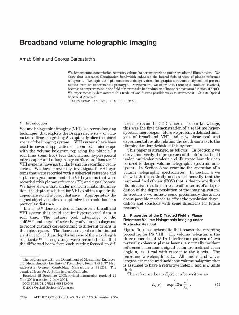
igure 1�a� is a schematic that shows the recordingrocedure for PR VHI. The volume hologram is thehree-dimensional �3-D� interference pattern of twoutually coherent planar beams; a normally incident
eference beam and a signal beam are inclined at anngle �s �� 1 rad with respect to the z axis. Theecording wavelength is �f. All angles and wave-engths are measured inside the volume hologram thats assumed to have a refractive index n and is L unitshick.
The reference beam Ef �r� can be written as
Ef�r� � exp�i2�z� � . (1)
f
Ti
Tesdm
Ft
fatllaonudwth
oalaoa
tte
ssco�adUv
Isfiws
pp
IaclA
A
st
Fp
he signal beam Es�r� can be expressed in the parax-al approximation as
Es�r� � exp�i2��1 ��s
2
2 � z�f
� i2��s
x�f� . (2)
he volume hologram is the recorded 3-D interfer-nce pattern of the reference and signal beams. It istored as a weak modulation ���r� �Ef Es�
2 of theielectric constant. The Bragg-matched term of theodulation is given by
���r� � exp�i2�
�f�x�s � z
�s2
2 �� . (3)
or the purpose of this derivation, we assume thathe hologram has an infinite lateral extent.
Figure 1�b� is a schematic of the readout procedureor PR VHI. An objective lens of focal length f andperture a is placed in front of the volume hologramo collimate the field arising from a probe point sourceocated at rp � �xp, yp, zp� and is emitting at a wave-ength �p. If a probe of wavelength �p � �f is placedt the Bragg-matched location �0, 0, �f �, then thebjective lens can perfectly collimate the probe and aormally incident probe beam is incident on the vol-me hologram. The volume hologram would theniffract a continuation of the signal beam, i.e., a planeave propagating in direction �s. A Fourier-
ransform lens �of focal length F� that is placed be-ind the hologram focuses the diffracted plane wave
ig. 1. Setup for PR VHI. �a� Recording and �b� readout with aoint source collimated by an objective lens.
20
nto the detector. However, if the probe is not ex-ctly Bragg matched, then the objective lens can noonger ensure that the field input to the hologram is
normally incident plane wave. In this situation,nly the Bragg-matched components of the input fieldre diffracted by the hologram.To examine the effect of Bragg mismatch, we use a
ransfer function13 approach. The 3-D Fourierransform of the dielectric constant modulation ��valuated at kp � kd, i.e.,
A�kp, kd� � S �
���r� � exp�i�kp � kd� � r�d3r,
(4)
pecifies the spatial response of the hologram to aingle spatial frequency in the input field. Hence, itan be thought of as the spatial-frequency response,r transfer function, of the volume hologram. In Eq.4�, S is a constant determined by the polarizationnd index modulation; our analysis normalizes theiffracted intensities, so this factor can be ignored.nder the paraxial approximation, the probe waveector is
kp � 2��fxx � fyy �1�p
�1 ��p
2� fx2 � fy
2�
2 � z� . (5)
n Eq. �5�, fx � cos �x��p and fy � cos �y��p are thepatial-frequency components of the input probeeld. �x and �y represent the angle that the plane-ave component makes with the x and y axes, re-
pectively.Similarly, because of the Fourier lens, we can ex-
ress the diffracted wave vector in the paraxial ap-roximation as
kd � 2�� x�
�p Fx �
y�
�p Fy �
1�p
�1 �� x�2 � y�2�
2F2 � z� .
(6)
n Eq. �6�, the spatial-frequency components x���pFnd y���pF are defined on the basis of the detectoroordinates �x�, y��. For the PR hologram of infiniteateral extent and thickness L described in Eq. �3�,˜ �x���pF, y���pF; fx, fy� is given by9
˜ � x�
�p F,
y�
�p F; fx, fy� � ��fx �
x�
�p F�
�s
�f���fy �
y�
�p F�� sinc�L�� x�2 � y�2�
2�p F2 ��p� fx
2 � fy2�
2�
�s2
2�f�� . (7)
Equation �7� can be used to calculate the spatialpectrum of the diffracted field Ed if the spatial spec-rum of the input field Ep is known according to
Ed� x�
�p F,
y�
�p F� � Ep� fx, fy�A
� � x�
� F,
y�
� F; fx, fy�dfxdfy. (8)
p p
September 2004 � Vol. 43, No. 27 � APPLIED OPTICS 5215
eptw
Icuhdst
Opd
Ttstdohavt
d�ltv
ftodfiwf
wp
ropm�tewtsb
ostt72lseu9t�tTwHpVsl�pa�taTpw
Ff
5
We first examine the response of a probe sourcemitting at a wavelength �p located at the front focallane of the objective lens. It will be convenient inhe later part of the analysis to define a normalizedavelength parameter
� ��p
�f. (9)
t is possible to Bragg match this probe source12 be-ause of the wavelength selectivity property of vol-me holographic gratings. To Bragg match theologram, a probe beam must be displaced in the xirection by an amount x that depends on � as can beeen from Eqs. �7� and �8�. This probe is then calledhe Bragg degenerate. The required displacement is
xf
��s�1 � ��
2. (10)
n the basis of Eqs. �7� and �10�, a Bragg-degeneraterobe is mapped onto a specific location x� on theetector that satisfies the relation
x�
F�
�s�1 � ��
2. (11)
he PR hologram is also degenerate in the y direc-ion.9 As a result, the volume hologram can image alit in the Bragg plane. From Eq. �11�, we see thathe volume hologram can also simultaneously mapifferent spectral frequencies onto different locationsn the detector plane. As a result, the PR volumeologram can be used to design a real-time spectrumnalyzer based on the dispersive properties of theolume holographic grating. This is discussed fur-her in Section 3.
We now examine a probe source that is axiallyisplaced by � from the Bragg-matched location �Eq.10��. Therefore the objective lens can no longer col-imate the probe field. Instead, the field incident onhe hologram is a spherical wave originating at theirtual object position
zp �f � f � ��
�
f 2
�(12)
or � �� f. Only the on-axis Fourier component ofhis spherical probe is Bragg matched; therefore theverall intensity diffracted from the hologram is re-uced. The analysis of the diffracted field is per-ormed in a manner similar to Ref. 9 by use of Weyl’sdentity to define the spatial spectrum of a sphericalave and with Eqs. �7� and �8�. The observed dif-
racted intensity on the detector is
I� x�, y�, ��
Ib circ� �r��
Fa��f 2�sinc2�L�s
�p
� �x�
F�
�s�1 � ��
2 �� , (13)
216 APPLIED OPTICS � Vol. 43, No. 27 � 20 September 2004
here Ib � I�x� � �sF, y� � 0, �� is the peak intensityroduced by the probe and
�r��2 � �x� � F��s�1 � ��
2�
��s�1 � ��
2f ��2
� � y��2
(14)
epresents the geometric image of the aperture of thebjective lens �equivalently, the defocused image of therobe� outside which the diffracted power is approxi-ately zero. It is interesting to note that when �p �
f, i.e., � � 1, the Bragg slit remains centered insidehe geometric image of the aperture for all �. How-ver, if � � 1, the center of the defocused spot changesith � according to Eq. �14�, and the Bragg slit appears
o move relative to the disk. This phenomenon has aignificant effect on the depth resolution of a broad-and PR VHI system, which we discuss in Section 4.We now present experimental verification of the the-
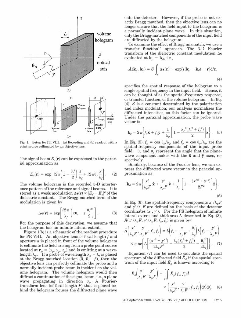
retical analysis discussed above. Figure 2 shows achematic of the experimental setup used. The objec-ive lens has a focal length f � 50.2 mm and an aper-ure a � 4 mm, the Fourier-transforming lens has F �5 mm, and the volume hologram was recorded in a-mm-thick crystal of LiNbO3 with a doubled Nd:YAGaser ��f � 532 nm� with a normal reference beam andignal beam inclined at �s � 0.2 rad; the diffractionfficiency of the hologram was �5%, and the camerased a JAI CV-235 industrial CCD with a pixel size of�m. The PR VHI system was read out in turn by
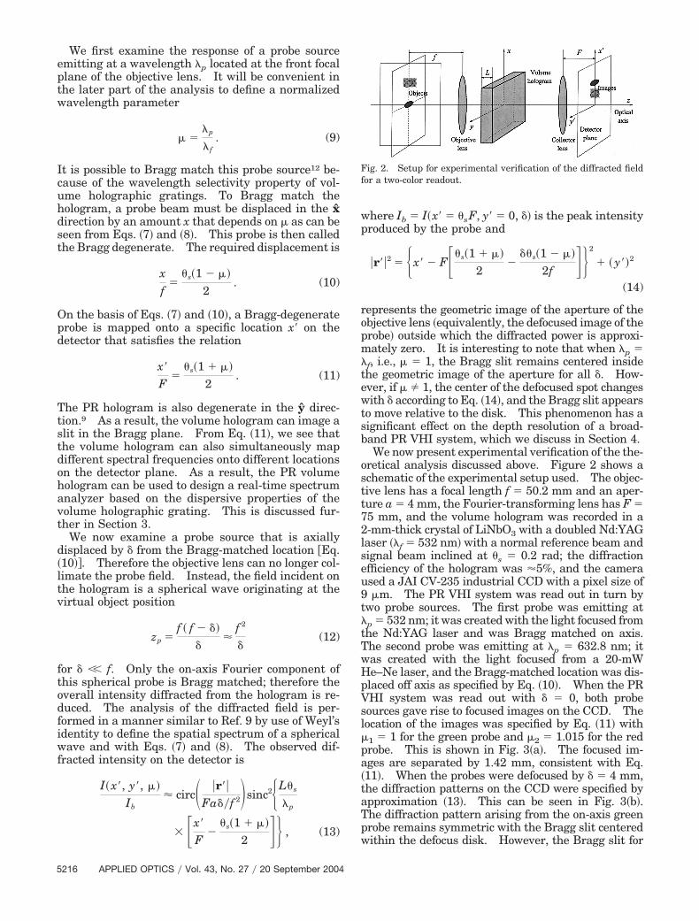
wo probe sources. The first probe was emitting atp � 532 nm; it was created with the light focused fromhe Nd:YAG laser and was Bragg matched on axis.he second probe was emitting at �p � 632.8 nm; itas created with the light focused from a 20-mWe–Ne laser, and the Bragg-matched location was dis-laced off axis as specified by Eq. �10�. When the PRHI system was read out with � � 0, both probeources gave rise to focused images on the CCD. Theocation of the images was specified by Eq. �11� with1 � 1 for the green probe and �2 � 1.015 for the redrobe. This is shown in Fig. 3�a�. The focused im-ges are separated by 1.42 mm, consistent with Eq.11�. When the probes were defocused by � � 4 mm,he diffraction patterns on the CCD were specified bypproximation �13�. This can be seen in Fig. 3�b�.he diffraction pattern arising from the on-axis greenrobe remains symmetric with the Bragg slit centeredithin the defocus disk. However, the Bragg slit for
ig. 2. Setup for experimental verification of the diffracted fieldor a two-color readout.
td
3
Wa4pPBtww
ItaIs
TacWp
VtmvfiocLbartpesW
Ft�A
Fnpmst6c4
he off-axis red probe is no longer centered within theisk and shifts by 117 �m, as predicted in Eq. �14�.
. Volume Holographic Spectrometer
e now examine the operation of a volume holograms a spectrometer. Consider the schematic of Fig.�a�, where the specimen of an unknown spectrum islaced at the front focus of the objective lens. TheR VHI system is designed so that the width of theragg slit is smaller than the pixel size on the detec-
or to reduce the cross talk between two adjacentavelengths. In other words, the detector pixelidth �x� must satisfy
�x� �F�p,max
L�s. (15)
n inequality �15�, �p,max is the longest wavelengthhat the PR VHI system can map onto the detector,nd it is limited by the aperture of the objective lens.n addition, the wavelength resolution of the PR VHIpectrum analyzer ��p is
��p �2�f�p,max
L� 2 . (16)
ig. 3. Experimentally observed diffracted field for readout withwo mutually incoherent Bragg-matched point sources emitting atp � 532 nm and �p � 632.8 nm. �a� Defocus � � 0, �b� � � 4 mm.ll lateral dimensions are in millimeters.
s
20
he k-sphere formulation13 can also be used to designPR VHI spectrum analyzer and is a useful graphical
onstruct to understand the behavior of the system.e do not go into the details of the k sphere in this
aper, but more information can be found in Ref. 14.We experimentally implemented the simple PR
HI spectrum analyzer of Fig. 4�a�. The illumina-ion was a broadband incoherent white-light sourceanufactured by Sunoptic Technologies �Jackson-
ille, Florida�. Different narrow-bandpass spectrallters were alternately placed at the focal plane of thebjective lens of focal length f � 100 mm. We re-orded the volume hologram in the same crystal ofiNbO3 described above using two mutually coherenteams ��f � 532 nm�: normally incident referencend signal beams inclined at an angle �s � 16° withespect to the normal. The same JAI CV-235 indus-rial CCD camera was used to capture the diffractionatterns. Each camera pixel was 9 �m wide, andight pixels were binned together to form a singlepectral measurement pixel of width �x� � 72 �m.e chose F � 75 mm to satisfy � � 540 nm in
ig. 4. Schematic of the PR VHI spectrometer. �a� The illumi-ation whose spectrum is unknown is placed at the Bragg-matchedlane of the PR VHI system; the illumination spectrum is theeasured one-dimensional intensity function �appropriately
caled� on the detector. �b� Measured spectrum where we usedwo narrow-bandpass optical filters at 488 � 6 nm �blue� and 532 �
nm �green�. The separation between the green and blue slitsorresponds to 43.92 nm, and the actual wavelength separation is4 nm.
p,max
September 2004 � Vol. 43, No. 27 � APPLIED OPTICS 5217
iontruTccass
4H
Wamts
wact
AIsmtirbecsp
piotbttcVba
attcobiobts
sawA
Fanp
Fp
5
nequality �15�. From these values, the spectral res-lution was estimated from Eq. �16� to be ��p � 3.66m. Figure 4�b� shows the Bragg slits observed onhe camera with the PR VHI system. Each slit cor-esponds to one bandpass spectral filter. The filterssed were 488 � 6 nm �blue� and 532 � 6 nm �green�.he centers of the slits are separated by 12 pixelsorresponding to a 43.92-nm difference between theenter wavelengths �the actual separation is 44 nm�,nd the full width at half-maximum �FWHM� of eachlit is approximately three pixels corresponding to apectral width of 10.98 nm.
. Depth Resolution of Planar Reference Volumeolographic Imaging under Broadband Illumination
e define the depth resolution for a PR VHI systems the FWHM of the point-spread function �PSF�easured by an integrating detector placed behind
he volume hologram. For a monochromatic PR VHIystem, the normalized PSF is calculated as9
Id
I0�
1�
0
2�
d� 0
1
d�� sinc2�aL sin �s�
�f 2 � sin �� ,
(17)
here I0 represents the peak Bragg-matched powert � � 0. The depth resolution �zFWHM for a mono-hromatic �wavelength of �p� point source located athe Bragg-matched position specified in Eq. �10� is9
�zFWHM �5.34f 2�p
a�s L. (18)
ll the variables in Eq. �18� were defined in Section 2.n addition to the wavelength dependence of �zFWHMpecified in Eq. �18�, the depth resolution for theonochromatic source with � � 1 is also effected by
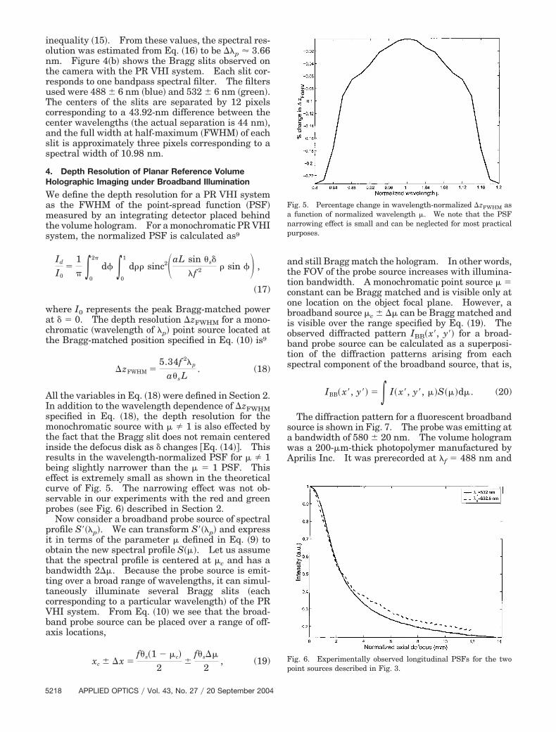
he fact that the Bragg slit does not remain centerednside the defocus disk as � changes �Eq. �14��. Thisesults in the wavelength-normalized PSF for � � 1eing slightly narrower than the � � 1 PSF. Thisffect is extremely small as shown in the theoreticalurve of Fig. 5. The narrowing effect was not ob-ervable in our experiments with the red and greenrobes �see Fig. 6� described in Section 2.Now consider a broadband probe source of spectral
rofile S���p�. We can transform S���p� and expresst in terms of the parameter � defined in Eq. �9� tobtain the new spectral profile S���. Let us assumehat the spectral profile is centered at �c and has aandwidth 2��. Because the probe source is emit-ing over a broad range of wavelengths, it can simul-aneously illuminate several Bragg slits �eachorresponding to a particular wavelength� of the PRHI system. From Eq. �10� we see that the broad-and probe source can be placed over a range of off-xis locations,
xc � �x �f�s�1 � �c�
2�
f�s��
2, (19)
218 APPLIED OPTICS � Vol. 43, No. 27 � 20 September 2004
nd still Bragg match the hologram. In other words,he FOV of the probe source increases with illumina-ion bandwidth. A monochromatic point source � �onstant can be Bragg matched and is visible only atne location on the object focal plane. However, aroadband source �c � �� can be Bragg matched ands visible over the range specified by Eq. �19�. Thebserved diffracted pattern IBB�x�, y�� for a broad-and probe source can be calculated as a superposi-ion of the diffraction patterns arising from eachpectral component of the broadband source, that is,
IBB� x�, y�� � I� x�, y�, ��S���d�. (20)
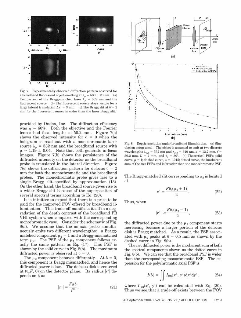
The diffraction pattern for a fluorescent broadbandource is shown in Fig. 7. The probe was emitting atbandwidth of 580 � 20 nm. The volume hologramas a 200-�m-thick photopolymer manufactured byprilis Inc. It was prerecorded at �f � 488 nm and
ig. 5. Percentage change in wavelength-normalized �zFWHM asfunction of normalized wavelength �. We note that the PSF
arrowing effect is small and can be neglected for most practicalurposes.
ig. 6. Experimentally observed longitudinal PSFs for the twooint sources described in Fig. 3.
pwlshs�idp7mpsOas
plrVm8nmtasd
tdap
Ta
T
tidad
tFtp
wT
FaCfllm
Fuw5cs
rovided by Ondax, Inc. The diffraction efficiencyas � � 60%. Both the objective and the Fourier
enses had focal lengths of 50.2 mm. Figure 7�a�hows the observed intensity for � � 0 when theologram is read out with a monochromatic laserource �p � 532 nm and the broadband source with
� 1.19 � 0.04. Note that both generate in-focusmages. Figure 7�b� shows the persistence of theiffracted intensity on the detector as the broadbandrobe is translated in the lateral direction. Figure�c� shows the diffraction pattern for defocus � � 2m for both the monochromatic and the broadband
robes. The monochromatic probe gives rise to aingle Bragg slit specified by approximation �13�.n the other hand, the broadband source gives rise towider Bragg slit because of the superposition of
everal spectral terms according to Eq. �20�.It is intuitive to expect that there is a price to be
aid for the improved FOV offered by broadband il-umination. This trade-off manifests itself in a deg-adation of the depth contrast of the broadband PRHI system when compared with the correspondingonochromatic case. Consider the schematic of Fig.
�a�. We assume that the on-axis probe simulta-eously emits two different wavelengths: a Bragg-atched component �1 � 1 and a Bragg-mismatched
erm �2. The PSF of the �1 component follows ex-ctly the same pattern as Eq. �17�. This PSF ishown by the solid curve in Fig. 8�b�. The maximumiffracted power is observed at � � 0.The �2 component behaves differently. At � � 0,
his component is Bragg mismatched, and hence theiffracted power is low. The defocus disk is centeredt ��sF, 0� on the detector plane. Its radius �r�� de-ends on � as
�r�� �Fa�
f 2 . (21)
ig. 7. Experimentally observed diffraction pattern observed forbroadband fluorescent object emitting at �p � 580 � 20 nm. �a�omparison of the Bragg-matched laser �p � 532 nm and theuorescent source. �b� The fluorescent source stays visible for a
arge lateral translation �x� � 3 mm. �c� The Bragg slit at � � 2m for the fluorescent source is wider than the laser Bragg slit.
20
he Bragg-matched slit corresponding to �2 is locatedt
x� �F�s��2 � 1�
2. (22)
hus, when
�r�� �F�s��2 � 1�
2, (23)
he diffracted power due to the �2 component startsncreasing because a larger portion of the defocusisk is Bragg matched. As a result, the PSF associ-ted with �2 peaks at � � 0.5 mm as shown by theashed curve in Fig. 8�b�.The net diffracted power is the incoherent sum of both
he spectral components shown as the dotted curve inig. 8�b�. We can see that the broadband PSF is widerhan the corresponding monochromatic PSF. The ex-ression for the polychromatic axial PSF is
I��� � IBB� x�, y��dx�dy�, (24)
here IBB�x�, y�� can be calculated with Eq. �20�.hus we see that a trade-off exists between the FOV
ig. 8. Depth resolution under broadband illumination. �a� Sim-lation setup used. The object is assumed to emit at two discreteavelengths �p,1 � 532 nm and �p,2 � 540 nm, a � 12.7 mm, f �0.2 mm, L � 2 mm, and �s � 30°. �b� Theoretical PSFs solidurve, � � 1; dashed curve, � � 1.015; dotted curve, the incoherentum of the two PSFs and is broader than the monochromatic PSF.
September 2004 � Vol. 43, No. 27 � APPLIED OPTICS 5219
aiu
bis
Ftbtt
5
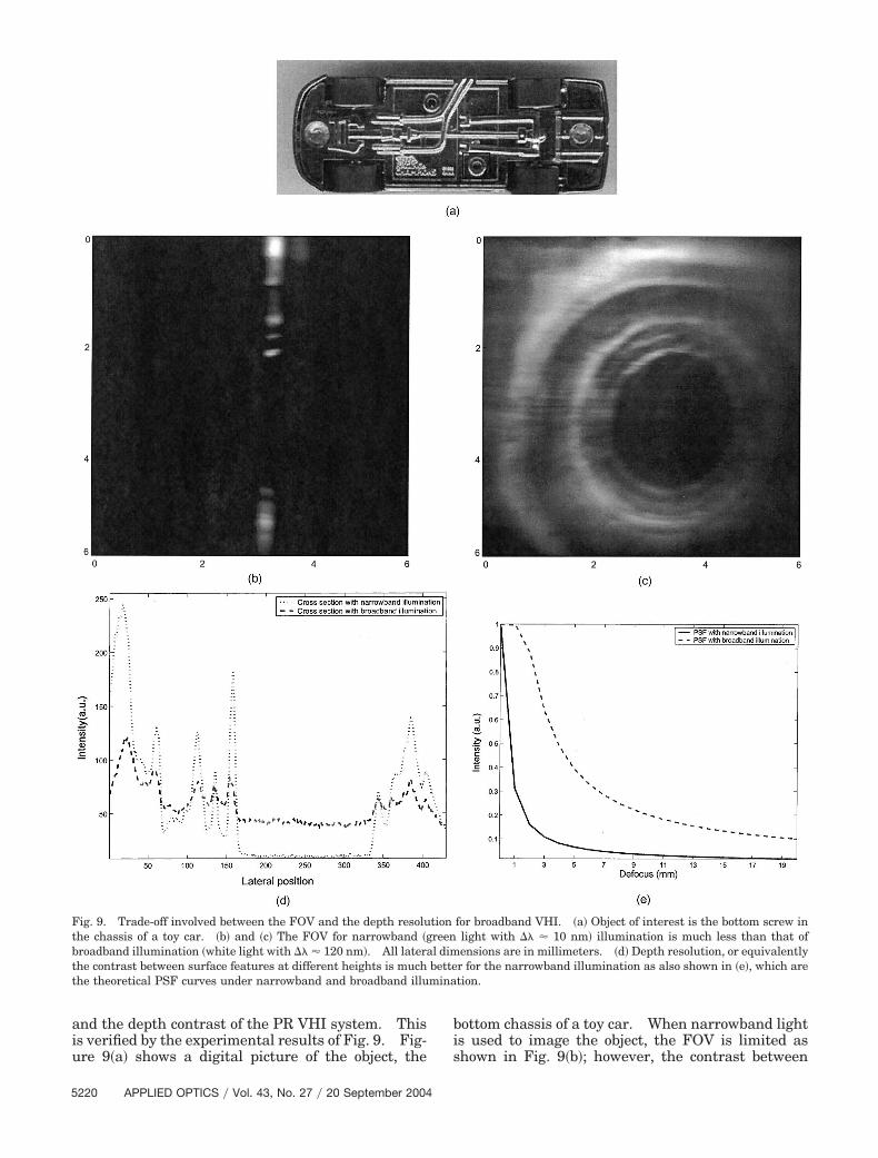
nd the depth contrast of the PR VHI system. Thiss verified by the experimental results of Fig. 9. Fig-re 9�a� shows a digital picture of the object, the
220 APPLIED OPTICS � Vol. 43, No. 27 � 20 September 2004
ottom chassis of a toy car. When narrowband lights used to image the object, the FOV is limited ashown in Fig. 9�b�; however, the contrast between
ig. 9. Trade-off involved between the FOV and the depth resolution for broadband VHI. �a� Object of interest is the bottom screw inhe chassis of a toy car. �b� and �c� The FOV for narrowband �green light with �� � 10 nm� illumination is much less than that ofroadband illumination �white light with �� � 120 nm�. All lateral dimensions are in millimeters. �d� Depth resolution, or equivalentlyhe contrast between surface features at different heights is much better for the narrowband illumination as also shown in �e�, which arehe theoretical PSF curves under narrowband and broadband illumination.
stObFoochtdm
5
IsafbrTlsooi
usVbtsFats
dltttdzmVtt
l
MTsCbt�
R
1
1
1
1
1
1
1
1
urfaces at different heights, which is a measure ofhe depth resolution, is high as shown in Fig. 9�d�.n the other hand, Fig. 9�c� shows the same objecteing imaged with broadband illumination. TheOV of the system now incorporates the entire objectf interest, and it is possible to take a one-shot imagef the object. However, the depth resolution, i.e., theontrast between the surfaces at different heights,as deteriorated as a consequence of an increase inhe FOV. We estimated that the depth resolutionegraded by a factor of 2.8 �see Fig. 9�e�� as the illu-ination bandwidth was increased.
. Discussion and Conclusions
t is worthwhile to mention that a trade-off alwayseems to manifest itself between the depth resolutionnd the FOV of the system. This has been observedor confocal microscopy when the pinhole is replacedy a slit and also for PR VHI when the hologram isead out with a line source instead of a point source.8he trade-off can also be expressed in terms of the
imited shift invariance of depth-selective imagingystems.15 However, it is possible to offset this res-lution degradation when several images of the objectf interest are acquired and when digital postprocess-ng methods are used.16
We have shown that a volume hologram can besed to design an imaging system that also acts as apectrum analyzer by exploiting the properties ofHI under broadband illumination. Thus we canuild four-dimensional �also referred to as hyperspec-ral� imaging systems6 that can measure both 3-Dpatial and spectral attributes of objects of interest.urthermore, we have shown that the enhanced FOVfforded by broadband illumination results in a de-erioration of depth resolution. We explored the rea-on for this trade-off and verified it experimentally.We have worked on several methods to offset the
egradation of depth resolution under broadband il-umination. The simplest scheme is to acquire mul-iple 3-D perspectives of the object and triangulatehese perspectives by a simple point multiplication ofhe obtained PSFs. More-sophisticated techniqueseal with image inversion with least-squares optimi-ation techniques.16 We are currently exploringore-sophisticated numerical techniques such as theiterbi-algorithm-based deconvolution17 and Radon
ransform approaches to recover information in realime.
We are grateful to Wenyang Sun and Tina Shih foraboratory assistance and to Kehan Tian, Robert
20
urphey, and Brian H. Miles for helpful discussions.his project was funded by the U.S. Air Force Re-earch Laboratories �Eglin Air Force Base� and theharles Stark Draper Laboratory. George Bar-astathis also acknowledges the support of the Na-ional Science Foundation through the CAREERformerly Young Investigator� Award.
eferences1. G. Barbastathis and D. J. Brady, “Multidimensional tomo-
graphic imaging using volume holography,” Proc. IEEE 87,2098–2120 �1999�.
2. E. N. Leith, A. Kozma, J. Upatnieks, J. Marks, and N. Massey,“Holographic data storage in three-dimensional media,” Appl.Opt. 5, 1303–1311 �1966�.
3. P. Yeh, Introduction to Photorefractive Nonlinear Optics�Wiley, New York, 1993�.
4. P. J. van Heerden, “Theory of optical information storage insolids,” Appl. Opt. 2, 393–400 �1963�.
5. G. Barbastathis, M. Balberg, and D. J. Brady, “Confocal mi-croscopy with a volume holographic filter,” Opt. Lett. 24, 811–813 �1999�.
6. W. Liu, D. Psaltis, and G. Barbastathis, “Real-time spectralimaging in three spatial dimensions,” Opt. Lett. 27, 854–856�2002�.
7. A. Sinha and G. Barbastathis, “Volume holographic telescope,”Opt. Lett. 27, 1690–1692 �2002�.
8. A. Sinha and G. Barbastathis, “Volume holographic imagingfor surface metrology at long working distances,” Opt. Exp. 11,3202–3209 �2003�, http:��www.opticsexpress.org.
9. A. Sinha, W. Sun, T. Shih, and G. Barbastathis, “Volume ho-lographic imaging in the transmission geometry,” Appl. Opt.43, 1–19 �2004�.
0. D. Psaltis, M. Levene, A. Pu, G. Barbastathis, and K. Curtis,“Holographic storage using shift multiplexing,” Opt. Lett. 20,782–784 �1995�.
1. G. Barbastathis, M. Levene, and D. Psaltis, “Shift multiplex-ing with spherical reference waves,” Appl. Opt. 35, 2403–2417�1996�.
2. D. Psaltis, F. Mok, and H. Y.-S. Li, “Nonvolatile storage inphotorefractive crystals,” Opt. Lett. 19, 210–212 �1994�.
3. G. Barbastathis and D. Psaltis, “Volume holographic multi-plexing methods,” in Holographic Data Storage, H. Coufal, D.Psaltis, and G. Sincerbox, eds. �Springer, New York, 2000�.
4. A. Sinha, “Imaging using volume holograms,” Ph.D. disserta-tion �Massachusetts Institute of Technology, Cambridge,Mass., 2004�.
5. A. Stein and G. Barbastathis, “Axial imaging necessitates lossof lateral shift invariance,” Appl. Opt. 41, 6055–6061 �2002�.
6. A. Sinha, W. Sun, and G. Barbastathis, “N-ocular volume ho-lographic imaging,” Appl. Opt. �2004�, submitted for publica-tion.
7. M. A. Neifeld and Y. Wu, “Parallel image restoration with atwo-dimensional likelihood-based algorithm,” Appl. Opt. 41,4812–4824 �2002�.
September 2004 � Vol. 43, No. 27 � APPLIED OPTICS 5221
Related Documents


![3D Holographic Millimeter-Wave Imaging for Concealed Metallic … · 2018. 6. 27. · Various imaging techniques include infrared imaging [ 5, 6], passive millimeter-wave (MMW) imaging](https://static.cupdf.com/doc/110x72/60cad3ad9597fd36557ea88e/3d-holographic-millimeter-wave-imaging-for-concealed-metallic-2018-6-27-various.jpg)
