IEEE TRANSACTIONS ON ANTENNAS AND PROPAGATION, VOL. XX, NO. X, YYYY 20XX 1 Broadband Flexible Fully Textile-Integrated Bandstop Frequency Selective Surface Leticia Alonso-Gonz´ alez, Student Member, IEEE, Samuel Ver-Hoeye, Member, IEEE, Miguel Fern´ andez-Garc´ ıa, and Fernando Las-Heras Andr´ es, Senior Member, IEEE Abstract—A broadband flexible fully textile-integrated band- stop frequency selective surface working at a central frequency of 5 GHz and presenting a 1.8 GHz bandwidth has been designed, manufactured and experimentally characterised. The frequency selective surface consists of two isolated layers of periodic square-shaped conductive rings and, due to its symmetries, its performance is largely independent of polarisation and angle of incidence. The textile frequency selective surface has been simulated and experimentally validated under bent conditions providing a stable performance. Index Terms—Flexible, frequency selective surface (FSS), bandstop, textile, textile-integrated circuits. I. I NTRODUCTION D URING the last few years, there has been an over- whelming interest in frequency selective surfaces (FSS) due to the wide number of applications in which they can be used [1], such as absorbers [2], artificial magnetic conductors [3], electromagnetic shielding, among others. The electromag- netic shielding can be achieved thanks to the bandpass [4] or bandstop [5, 6] responses of the FSS, depending on the periodic structure. Different approaches have been used to develop FSS, from conventional designs based on resonators implemented over rigid substrates [7–9], FSS based on 3D printing [10], the use of high permittivity ceramic materials in order to avoid conductive materials [11], thicker multiband designs based on substrate integrated waveguide (SIW) technology [12] or multilayered designs [13]. The before mentioned alterna- tives present different advantages, such as the possibility of achieving high precision details in the fabricated prototypes. Nevertheless, none of them are flexible or washable through industrial processes, and their dimensions are constrained by the prototyping machine or 3D printer, leading to a limited number of unit cells in the manufactured design. Some solutions have also been developed to integrate the FSS into the textile. As an example, in [14], a flexible and portable textile-reflectarray backed by an FSS is proposed using two separate embroidered fabrics connected through Velcros. However, this solution requires two fabrics and is not appropiate for low profile applications. In [15], an inkjet This work has been supported by Gobierno de Espa˜ na TEC2015-72110- EXP, MINECO-17-TEC2016-80815-P and FPU14/00016 grant, and by the Gobierno del Principado de Asturias (PCTI)/FEDER-FSE under projects IDI/2016/000372 and IDI/2017/000083. The authors are with the Signal Theory and Communications Area, Depart- ment of Electrical Engineering, University of Oviedo, Gij´ on E-33203, Spain (e-mail: [email protected] - [email protected]). printed FSS over a fabric is presented, whereas in [16], an FSS is proposed employing the screen printing technology. These procedures present the difficulty of achieving a thin and conductive printed layer over an uneven substrate, leading to the necessity of double-printing the layout or using interme- diate impermeable coatings between the fabric and the ink, increasing the number of required subprocesses. Furthermore, the ink must be properly printed on the fabric to avoid its deterioration due to the wear out. With the aim of pushing textile components to the mi- crowave range, a weaving-based procedure to design, simulate and manufacture RF textile-integrated structures has already been thoroughly discussed in [17, 18]. Moreover, this weaving- based procedure presents the advantage of avoiding posterior adhesives, coatings or sewing procedures to manufacture the flexible prototypes. For applications such as momentarily shielding a room from a certain frequency, a flexible woven structure can work as a smart curtain, which is easy to install, uninstall, keep or transport. Moreover, industrial weaving looms allow the automatically manufacturing of very large prototypes, in comparison with standard prototyping machines. For this reason, flexible textile-integrated FSS can overcome the problems attributed to standard FSS, opening a new field of research. In this paper, a broadband flexible fully textile-integrated bandstop FSS has been designed. It can be manufactured with existing industrial textile machinery, making it suitable for mass production in larger dimensions than conventional FSS based on rigid substrates. The proposed FSS is based on two isolated layers of periodic conductive square-rings and its performance is independent of the incident wave direction and polarisation. Moreover, the proposed FSS has been simulated and experimentally validated under bent conditions, providing a stable performance. The paper is organised as follows. In Section II, the structure of the FSS will be explained. In Section III, a description of the employed materials will be presented. In Section IV, the translation into a woven FSS will be discussed. In Section V, the simulated data will be presented. In Section VI, the fab- rication process of the FSS will be explained. In Section VII, the experimental validation will be presented and discussed. II. STRUCTURE OF THE FSS A broadband bandstop FSS is proposed to work at 5 GHz with a 1.8 GHz bandwidth. The FSS has been designed from a unit cell to which periodic boundary conditions (PBC)

Welcome message from author
This document is posted to help you gain knowledge. Please leave a comment to let me know what you think about it! Share it to your friends and learn new things together.
Transcript
IEEE TRANSACTIONS ON ANTENNAS AND PROPAGATION, VOL. XX, NO. X, YYYY 20XX 1
Broadband Flexible Fully Textile-IntegratedBandstop Frequency Selective Surface
Leticia Alonso-Gonzalez, Student Member, IEEE, Samuel Ver-Hoeye, Member, IEEE,Miguel Fernandez-Garcıa, and Fernando Las-Heras Andres, Senior Member, IEEE
Abstract—A broadband flexible fully textile-integrated band-stop frequency selective surface working at a central frequency of5 GHz and presenting a 1.8 GHz bandwidth has been designed,manufactured and experimentally characterised. The frequencyselective surface consists of two isolated layers of periodicsquare-shaped conductive rings and, due to its symmetries, itsperformance is largely independent of polarisation and angleof incidence. The textile frequency selective surface has beensimulated and experimentally validated under bent conditionsproviding a stable performance.
Index Terms—Flexible, frequency selective surface (FSS),bandstop, textile, textile-integrated circuits.
I. INTRODUCTION
DURING the last few years, there has been an over-whelming interest in frequency selective surfaces (FSS)
due to the wide number of applications in which they can beused [1], such as absorbers [2], artificial magnetic conductors[3], electromagnetic shielding, among others. The electromag-netic shielding can be achieved thanks to the bandpass [4]or bandstop [5, 6] responses of the FSS, depending on theperiodic structure.
Different approaches have been used to develop FSS, fromconventional designs based on resonators implemented overrigid substrates [7–9], FSS based on 3D printing [10], theuse of high permittivity ceramic materials in order to avoidconductive materials [11], thicker multiband designs basedon substrate integrated waveguide (SIW) technology [12]or multilayered designs [13]. The before mentioned alterna-tives present different advantages, such as the possibility ofachieving high precision details in the fabricated prototypes.Nevertheless, none of them are flexible or washable throughindustrial processes, and their dimensions are constrained bythe prototyping machine or 3D printer, leading to a limitednumber of unit cells in the manufactured design.
Some solutions have also been developed to integrate theFSS into the textile. As an example, in [14], a flexible andportable textile-reflectarray backed by an FSS is proposedusing two separate embroidered fabrics connected throughVelcros. However, this solution requires two fabrics and isnot appropiate for low profile applications. In [15], an inkjet
This work has been supported by Gobierno de Espana TEC2015-72110-EXP, MINECO-17-TEC2016-80815-P and FPU14/00016 grant, and by theGobierno del Principado de Asturias (PCTI)/FEDER-FSE under projectsIDI/2016/000372 and IDI/2017/000083.
The authors are with the Signal Theory and Communications Area, Depart-ment of Electrical Engineering, University of Oviedo, Gijon E-33203, Spain(e-mail: [email protected] - [email protected]).
printed FSS over a fabric is presented, whereas in [16], anFSS is proposed employing the screen printing technology.These procedures present the difficulty of achieving a thin andconductive printed layer over an uneven substrate, leading tothe necessity of double-printing the layout or using interme-diate impermeable coatings between the fabric and the ink,increasing the number of required subprocesses. Furthermore,the ink must be properly printed on the fabric to avoid itsdeterioration due to the wear out.
With the aim of pushing textile components to the mi-crowave range, a weaving-based procedure to design, simulateand manufacture RF textile-integrated structures has alreadybeen thoroughly discussed in [17, 18]. Moreover, this weaving-based procedure presents the advantage of avoiding posterioradhesives, coatings or sewing procedures to manufacture theflexible prototypes. For applications such as momentarilyshielding a room from a certain frequency, a flexible wovenstructure can work as a smart curtain, which is easy to install,uninstall, keep or transport. Moreover, industrial weavinglooms allow the automatically manufacturing of very largeprototypes, in comparison with standard prototyping machines.For this reason, flexible textile-integrated FSS can overcomethe problems attributed to standard FSS, opening a new fieldof research.
In this paper, a broadband flexible fully textile-integratedbandstop FSS has been designed. It can be manufacturedwith existing industrial textile machinery, making it suitablefor mass production in larger dimensions than conventionalFSS based on rigid substrates. The proposed FSS is based ontwo isolated layers of periodic conductive square-rings and itsperformance is independent of the incident wave direction andpolarisation. Moreover, the proposed FSS has been simulatedand experimentally validated under bent conditions, providinga stable performance.
The paper is organised as follows. In Section II, the structureof the FSS will be explained. In Section III, a description ofthe employed materials will be presented. In Section IV, thetranslation into a woven FSS will be discussed. In Section V,the simulated data will be presented. In Section VI, the fab-rication process of the FSS will be explained. In Section VII,the experimental validation will be presented and discussed.
II. STRUCTURE OF THE FSS
A broadband bandstop FSS is proposed to work at 5 GHzwith a 1.8 GHz bandwidth. The FSS has been designed froma unit cell to which periodic boundary conditions (PBC)
IEEE TRANSACTIONS ON ANTENNAS AND PROPAGATION, VOL. XX, NO. X, YYYY 20XX 2
TABLE IDIMENSIONS OF THE FSS
Dimensions (mm)
Top layer Bottom layer Unit cell
LT WT LB WB L H
34 5 30 7.5 45 1
have been applied, leading to an ideal infinite FSS. Figure1a represents an overview of the unit cell and the boundaryconditions. The tangential component of the magnetic field,HT, in the two boundaries which are parallel to the YZ–planeis zero and the tangential component of the electric field, ET,in the two boundaries which are parallel to the XZ–planeis zero, leading to a PBC environment. The unit cell hasbeen iluminated with a plane wave, whose polarisation axisis vertically oriented (Y–axis), propagating in the k directionfrom port 1 to port 2, so that the S21 parameter can becalculated.
Figure 1b depicts a side view of the unit cell and itslayers. The unit cell is composed of three layers, the topand the bottom layers which are separated by an isulatinglayer (middle layer), leading to a total height of the unit celldenoted by H. The top layer of the unit cell is composed ofa square-shaped ring resonator, whose side and width are LTand WT, respectively, as it can be seen in Fig. 1c. Similarly,the bottom layer of the unit cell is composed of a square-shaped ring resonator, whose side and width are LB and WB,respectively, as it can be seen in Fig. 1d. The total length ofthe square-shaped unit cell is L. All the mentioned dimensionsare summarised in Table I.
The proposed FSS is fully integrated in textile, therefore,the conductive and dielectric parts are manufactured usingdifferent types of threads. The employed materials will beexplained in Section III and the translation into a wovenprototype will be detailed in Section IV. For this reason, thedimensions summarised in Table I have been calculated oncea sample of the textile substrate has been electromagneticallycharacterised, as it will be explained in Section IV.
III. DESCRIPTION OF THE EMPLOYED MATERIALS
Different materials have been employed for the design of theFSS, for both the weft and the warp directions. The weft direc-tion coincides with the width of the fabric and, consequently,with the width of the loom, while the warp direction coincideswith the length of the fabric. The warp threads are previouslyassembled in the loom, whereas the weft yarns are successivelyinserted in the woven structure during the fabrication process.In the proposed FSS, the warp direction coincides with thedirection of the Y–axis. Consequently, the weft direction isoriented in the X–axis direction. In this section, a descriptionof the employed materials and, therefore, the structure of thewoven substrate is presented.
A. Description of the Electrically Conductive Materials
Electrically conductive Shieldex 117f17 2-ply yarns, [19],with a resistance of 3.9 Ω/cm have been used for the conduc-
X
Y
ZE
H
k
ET = 0
HT = 0Port 1
Port 2
D
(a)
Top layer
Middle layer
Bottom layer
Insulator
H
(b)
WT
LT
(c)
WB
LB
L
(d)
Fig. 1. Schematic drawing of the proposed unit cell, conductive materials(yellow) and dielectric materials (grey). The dimensions are summarised inTable I. (a) Overview of the unit cell and boundary conditions (D = 1.5 m).(b) Side view of the unit cell and its layers. (c) Top layer of the unit cell andits dimensions. (d) Bottom layer of the unit cell and its dimensions.
tive warp and weft threads. The ply number means the numberof initial threads that are twisted around one another to createa single and stronger thread. These threads consist of two pliesand each ply is formed by 17 filaments and weights 117 dtex.The diameter of the Shieldex 117f17 2-ply yarns is dShieldex =0.3 mm. Figure 2a shows a sample of a Shieldex 117f17 2-plyyarn, whereas in Fig. 2b the unraveled filaments from a singleply are depicted.
B. Description of the Dielectric Materials
For the dielectric parts of the FSS two different types ofthreads have been used. For the weft threads, high tenacitywhite polyethersulfone (commonly known as PES) 550 dtexhas been employed. The diameter of the PES yarns is dPES

IEEE TRANSACTIONS ON ANTENNAS AND PROPAGATION, VOL. XX, NO. X, YYYY 20XX 3
Ply 1 Ply 2
(a)
Filament
(b)
Fig. 2. Employed conductive thread. (a) Shieldex 117f17 2-ply thread sample.(b) Unraveled filaments from one single ply.
(a)
Filament
(b)
Fig. 3. Employed dielectric weft thread. (a) High tenacity PES 550 dtexthread sample. (b) Unraveled filaments.
= 0.3 mm. Figure 3a shows a sample of a high tenacity PESthread, whereas Fig. 3b describes the unraveled filaments ofthe sample sample. For the warp threads, white polyethylene-terephthalate (commonly known as PET or polyester) 76f24,which means that it is composed of 76 filaments with 24dtex, has been used. The diameter of the PET yarns is dPET =0.1 mm. Figure 4a depicts a sample of a PET 76f24 thread,whereas Fig. 4b shows the unraveled filaments of the samesample.
IV. DESIGN OF THE WOVEN FSS
A broadband bandstop FSS is proposed. The FSS hasbeen designed from a unit cell to which PBC has beenapplied, leading to an ideal infinite FSS. Nevertheless, a finiteversion composed of 9× 9 unit cells has also been simulated
(a)
Filament
(b)
Fig. 4. Employed dielectric warp thread. (a) PET 76f24 dtex thread sample.(b) Unraveled filaments.
1 mm
Weft direction
War
p di
rect
ion
(a)
1 mmWarp PET
Weft PES
(b)
Fig. 5. Woven substrate. (a) Top view. (b) Side view.
to compare the simulations with the measurements. First, asample of the dielectric substrate has been manufactured andelectromagnetically characterised in order to design the FSSand, therefore, translate it into a woven prototype.
The substrate of the FSS is a multilayered fabric composedof three layers of weft PES threads interwoven using warpPET yarns, leading to a satin woven structure. Due to the airgaps between the threads, a sample of the substrate has beenmanufactured and electromagnetically characterised using anAgilent Technologies 85072A Split Cylinder Resonator andits relative dielectric permittivity and loss tangent have beenfound to be εsubs = 1.7 and tan(δ)subs = 0.00362, respectively.Figure 5a represents the top view of a sample of the wovensubstrate whereas Fig. 5b shows a side view of the wovensubstrate.
The woven prototype is composed of three layers: twodielectric layers in which the conductive square-rings areinserted, separated by an insulating layer. The three layers areidentical, except for the positions where the dielectric threadshave been substituted by conductive threads to implementthe resonators. The conductive square rings placed in the toplayer are translated into 5 Shieldex threads as shown in Fig.6a, which will be simulated as 5 conductive strips, separateda distance sT between centres and whose widths are dT =dShieldex, as it can be seen in Fig. 6c. The conductive squarerings placed in the bottom layer are translated into 7 Shieldex

IEEE TRANSACTIONS ON ANTENNAS AND PROPAGATION, VOL. XX, NO. X, YYYY 20XX 4
WT
LT
(a)
WB
LB
L
(b)
dTsT
(c)
dBsB
(d)
Fig. 6. Schematic drawing of the proposed unit cell and its dimensions.The dimensions are summarised in Table II. (a) Top view. (b) Bottom view.(c) Detailed view of the dimensions (top view). (d) Detailed view of thedimensions (bottom view).
TABLE IIDIMENSIONS OF THE WOVEN FSS
Dimensions (mm)
Top layer Bottom layer Unit cell
LT WT dT sT LB WB dB sB L H
34 5 0.3 1.175 30 7.5 0.3 1.2 45 1
threads as shown in Fig. 6b, which will be simulated as 7conductive strips, separated a distance sB between centres andwhose widths are dB = dShieldex, as it can be seen in Fig. 6d.The mentioned dimensions are summarised in Table II.
V. SIMULATIONS
The proposed design has been analysed using the 3D full–wave High Frequency Structure Simulator (HFSS) software.First, an infinite FSS modelled as one unit cell (describedin Section IV) with PBC has been simulated under normalincidence conditions and the result has been compared withthe simulation of a finite structure. Then, the behaviour of thefinite FSS in terms of angle of polarisation, angle of incidenceand radius of curvature has been studied.
Two infinite arrays of resonators have been simulated ap-plying PBC to a unit cell placing two ports at a distance ofD/2 = 0.75 m from each side of the FSS, respectively, as pre-viously illustrated in Fig. 1a. In Fig. 7, the individual behaviourof the resonators, using PCB, in the top and bottom layers hasbeen represented. The resonators in the top and bottom layerspresent a bandstop behaviour at a central frequency of 3.4 GHzand 5.1 GHz, respectively. The simulated individual behaviourof the electric field is depicted in Fig. 8. Figure 8a representsthe electric field at 5.1 GHz for a unit cell with PBC composedonly of the top layer resonators, whereas Fig. 8b represents
Frequency (GHz)
|S21| (
dB)
2
20
-20
-40
-602.5 3.5 4 5.5 7
Top layer resonatorsBottom layer resonators
0
3 4.5 5 6 6.5
Fig. 7. Simulated individual behaviour of the resonators in the top and bottomlayers using the PCB conditions.
their behaviour at 3.4 GHz. Figure 8c represents the electricfield at 3.4 GHz for a unit cell with PBC composed only ofthe bottom layer resonators, whereas Fig. 8d represents theirbehaviour at 5.1 GHz.
An infinite FSS (using both arrays of resonators) has beensimulated, leading to a broadband bandstop behaviour of thecomplete FSS, as a result of the coupling phenomena betweenthe two layers of resonators. A finite version 9 × 9 unit–cell has also been simulated in the middle between two hornantennas separated a distance D. The simulated S21 parameter,normalised by the response in the abscence of the FSS, isshown in Fig. 9a. The dimensions of the simulated hornsare identical to the dimensions of the real horns which havebeen used for the experimental validation. The comparisonbetween the simulation of both |S21| parameters can be seenin Fig. 10. The non-shaded range of frequencies represents thefrequencies in which a single-mode operation of the horns isguaranteed.
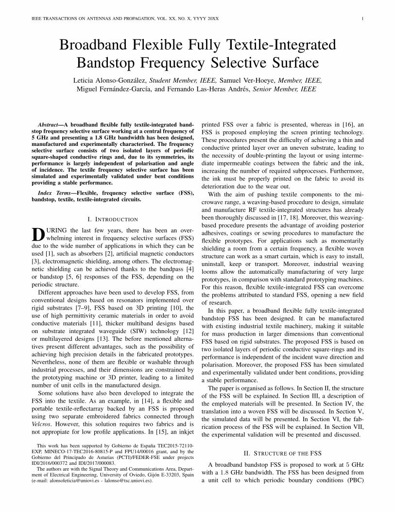
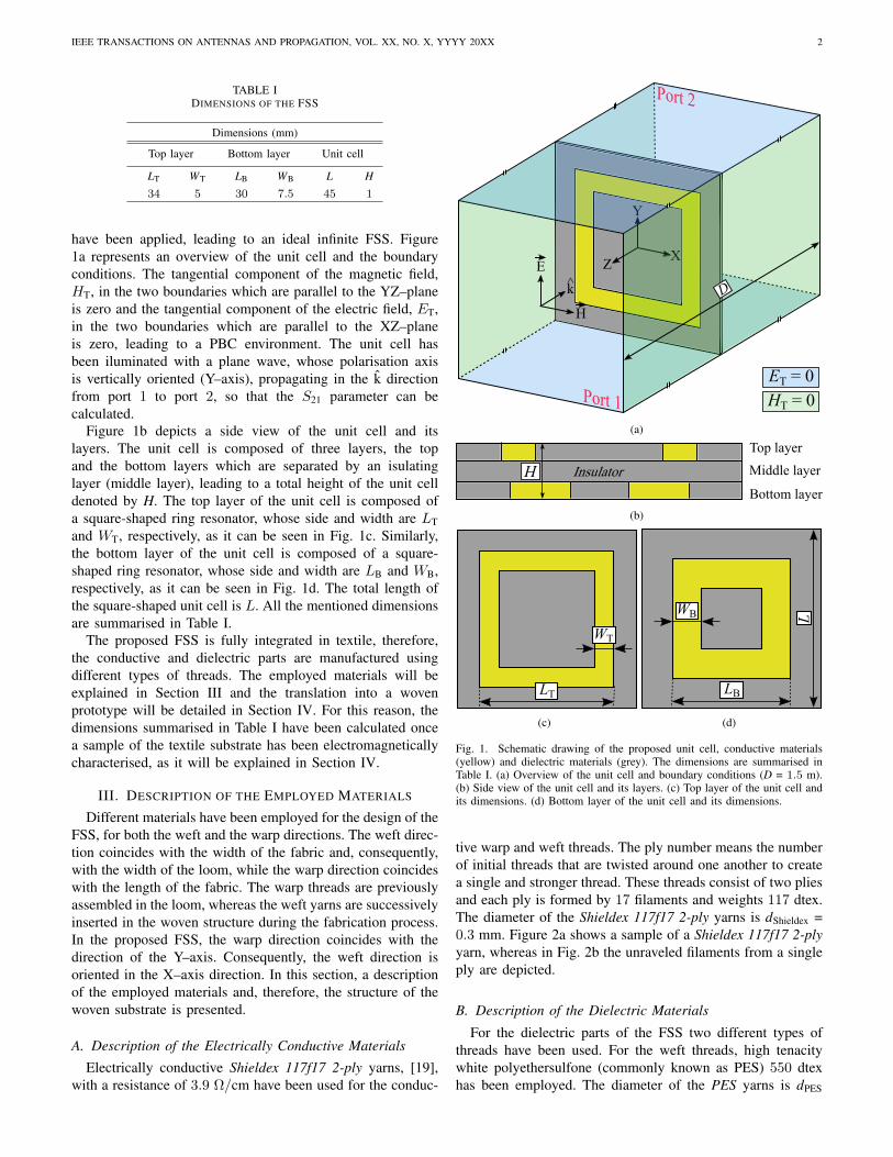
To study the behaviour of the designed FSS in terms ofthe angle of polarisation, the FSS has been simulated rotatingit around its Z–axis, from θ = 0 to θ = 45 as depicted inFig. 9b. The simulated |S21| parameter for the different anglesof polarisation is shown in Fig. 11. Although the minimumvalue of the |S21| parameter is modified with the angle ofpolarisation, the attenuation level remains over 10 dB in thenon–shaded region. Consequently, the FSS presents an stableperformance in terms of the angle of polarisation.
To study the behaviour of the designed FSS in terms ofthe angle of incidence, the FSS has been simulated rotating itaround its Y–axis, from φ = 0 to φ = 45 as depicted in Fig.9c. The simulated |S21| parameter for the different angles ofincidence is shown in Fig. 12. The simulated FSS presents astable performance in terms of its angle of incidence.
To study the behaviour of the designed FSS in terms of itsradius of curvature, the FSS has been simulated bending itaround a cylinder whose axis is parallel to the X–axis, from aradius R = 400 mm to R = 600 mm, as depicted in Fig. 9d. Theminimum distance between the FSS and the transmiter horn isD/2. The simulated |S21| parameter for the different radii ofcurvature is shown in Fig. 13. Although the minimum valueof the |S21| parameter is modified with the radius of curvature,the attenuation level remains over 10 dB in the non–shadedregion. Consequently, the FSS presents an stable performancein terms of the radius of curvature.

IEEE TRANSACTIONS ON ANTENNAS AND PROPAGATION, VOL. XX, NO. X, YYYY 20XX 5
Z X
Y
(a)
Z X
Y
(b)
Z X
Y
(c)
Z X
Y
(d)
0-10.9-21.8-27.3-38.2-49.1
dB
(e)
Fig. 8. Simulated individual behaviour of the normalised electric field (PBC).(a) Resonators in the top layer at 5.1 GHz. (b) Resonators in the top layer at3.4 GHz. (c) Resonators in the bottom layer at 3.4 GHz. (d) Resonators inthe bottom layer at 5.1 GHz. (e) Common scale for (a) to (d) representations.
VI. FABRICATION PROCESS
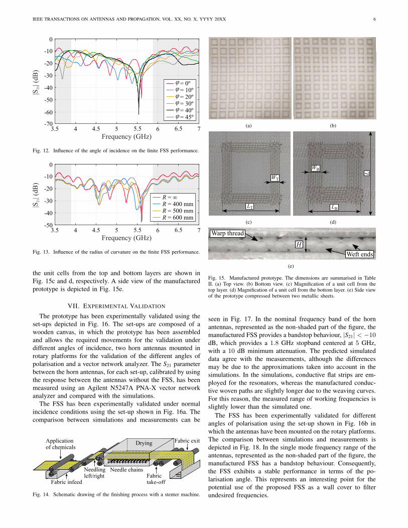
A finite 9× 9 unit cells FSS has been manufactured usingan industrial MuGrip loom. The manufacturing process hasbeen based on satin weaving. The conductive warp yarnsare previously mounted in the loom and the conductive weftthreads are inserted in the fabric during the fabrication processleading to two conductive lattices in either side of the fabric,instead of the required square-rings. As the leftover conductivematerial has not been interwoven in the fabric during themanufacturing process, but it has been left loose, it then can beeasily removed. A finishing process is needed after removingthe fabric from the loom in order to achieve the requirements.Figure 14 depicts a generic finishing process which starts withthe insertion of the fabric in liquid chemicals, then needlingthe fabric and finally applying heat to dry it. The manufacturedFSS has been heated at 185 on the frame of the stentermachine.
The top and bottom views of the manufactured prototypecan be seen in Fig. 15a and b, whereas a magnification of
X
Y
ZD
(a)
θX
Y
Z
(b)
φX
Y
Z
(c)
RX
Y
Z
(d)
Fig. 9. Schematic drawings of the different set–ups to simulate the finite FSS(D = 1.5 m). (a) Normal incidence. (b) Angle of polarisation. (c) Angle ofincidence. (d) Radius of curvature.
Frequency (GHz)
|S21| (
dB)
3.5
0
-10
-20
-30
-40
-504 4.5 5 5.5 6 6.5 7
Infinite FSS (PBC)Finite FSS (9⨯9 unit cells)
Fig. 10. Simulated |S21| parameter for an infinite FSS (unit cell and PBC)and for a finite FSS (9× 9 unit cells).
Frequency (GHz)
|S21| (
dB)
3.5
0
-10
-20
-30
-40
-50
4 4.5 5 5.5 6 6.5 7-60
θ = 0ºθ = 10ºθ = 20ºθ = 30ºθ = 40ºθ = 45º
Fig. 11. Influence of the polarisation angle on the finite FSS performance.
IEEE TRANSACTIONS ON ANTENNAS AND PROPAGATION, VOL. XX, NO. X, YYYY 20XX 6
Frequency (GHz)
|S21| (
dB)
3.5
0
-10
-20
-30
-40
-50
4 4.5 5 5.5 6 6.5 7
-60
= 0º= 10º= 20º= 30º= 40º= 45º
φφφφφφ
-70
Fig. 12. Influence of the angle of incidence on the finite FSS performance.
Frequency (GHz)
|S21| (
dB)
3.5
0
-10
-20
-30
-40
-504 4.5 5 5.5 6 6.5 7
R = ∞R = 400 mmR = 500 mmR = 600 mm
Fig. 13. Influence of the radius of curvature on the finite FSS performance.
the unit cells from the top and bottom layers are shown inFig. 15c and d, respectively. A side view of the manufacturedprototype is depicted in Fig. 15e.
VII. EXPERIMENTAL VALIDATION
The prototype has been experimentally validated using theset-ups depicted in Fig. 16. The set-ups are composed of awooden canvas, in which the prototype has been assembledand allows the required movements for the validation underdifferent angles of incidence, two horn antennas mounted inrotary platforms for the validation of the different angles ofpolarisation and a vector network analyzer. The S21 parameterbetween the horn antennas, for each set-up, calibrated by usingthe response between the antennas without the FSS, has beenmeasured using an Agilent N5247A PNA-X vector networkanalyzer and compared with the simulations.
The FSS has been experimentally validated under normalincidence conditions using the set-up shown in Fig. 16a. Thecomparison between simulations and measurements can be
Applicationof chemicals
Fabric infeed
Needling left/right
Needle chainsFabric take-off
Fabric exitDrying
Fig. 14. Schematic drawing of the finishing process with a stenter machine.
(a) (b)
WT
LT
(c)
L
LB
WB
(d)
Warp thread
Weft ends
H
(e)
Fig. 15. Manufactured prototype. The dimensions are summarised in TableII. (a) Top view. (b) Bottom view. (c) Magnification of a unit cell from thetop layer. (d) Magnification of a unit cell from the bottom layer. (e) Side viewof the prototype compressed between two metallic sheets.
seen in Fig. 17. In the nominal frequency band of the hornantennas, represented as the non-shaded part of the figure, themanufactured FSS provides a bandstop behaviour, |S21| < −10dB, which provides a 1.8 GHz stopband centered at 5 GHz,with a 10 dB minimum attenuation. The predicted simulateddata agree with the measurements, although the differencesmay be due to the approximations taken into account in thesimulations. In the simulations, conductive flat strips are em-ployed for the resonators, whereas the manufactured conduc-tive woven paths are slightly longer due to the weaving curves.For this reason, the measured range of working frequencies isslightly lower than the simulated one.
The FSS has been experimentally validated for differentangles of polarisation using the set-up shown in Fig. 16b inwhich the antennas have been mounted on the rotary platforms.The comparison between simulations and measurements isdepicted in Fig. 18. In the single mode frequency range of theantennas, represented as the non-shaded part of the figure, themanufactured FSS has a bandstop behaviour. Consequently,the FSS exhibits a stable performance in terms of the po-larisation angle. This represents an interesting point for thepotential use of the proposed FSS as a wall cover to filterundesired frequencies.

IEEE TRANSACTIONS ON ANTENNAS AND PROPAGATION, VOL. XX, NO. X, YYYY 20XX 7
Rx horn
FSSPNA-X
Tx horn
D
(a)
Rotary platformRotary platform
θθ
(b)
Rotary canvas
φ
(c)
R
(d)
Fig. 16. Measurement set-ups (D = 1.5 m). (a) Normal incidence. (b)Polarisation angle set-up. (c) Angle of incidence set-up. (d) Bending angleset-up.
The FSS has also been experimentally validated for differentangles of incidence using the set-up shown in Fig. 16c witha rotary canvas. The comparison between simulations andmeasurements can be seen in Fig. 19. As predicted, in thesingle mode frequency range of the antennas, the manufacturedFSS has a bandstop behaviour. Therefore, the FSS also exhibits
Frequency (GHz)
|S21| (
dB)
3.5
0
-10
-20
-30
-40
-504 4.5 5 5.5 6 6.5 7
Infinite FSS (sim.)Finite FSS (sim.)
Finite FSS (meas.)
Fig. 17. Simulated |S21| parameter for an infinite FSS (unit cell and PBC)and for a finite FSS (9 × 9 unit cells) vs. measured |S21| parameter for themanufactured FSS.
Frequency (GHz)
|S21| (
dB)
3.5
0
-10
-20
-30
-40
-50
4 4.5 5 5.5 6 6.5 7-60
θ = 0ºθ = 10ºθ = 20ºθ = 30ºθ = 40º
sim.sim.sim.sim.sim.sim.
meas.meas.meas.meas.meas.meas. θ = 45º
Fig. 18. Simulated and measured influence of the polarisation angle on thefinite FSS performance.
a stable performance in terms of the angle of incidence, rein-forcing its applicability in the aforementioned wall covering.
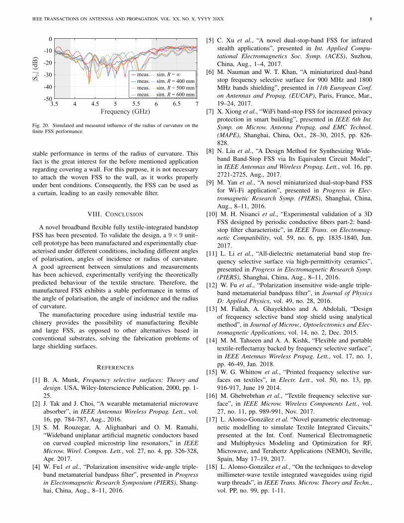
Due to its flexibility, the FSS has been experimentallyvalidated for different radii of curvature using the set-upshown in Fig. 16d. The FSS has been bent around differentcardboard pieces to achieve the required radius of curvature.The comparison between simulations and measurements isshown in Fig. 20. As predicted in the simulations, in the singlemode frequency range of the antennas, the manufactured FSShas a bandstop behaviour. Consequently, the FSS exhibits a
Frequency (GHz)
|S21| (
dB)
3.5
0
-10
-20
-30
-40
-50
4 4.5 5 5.5 6 6.5 7
-60
= 0º= 10º= 20º= 30º= 40º
sim.sim.sim.sim.sim.sim. = 45º
φφφφφφ
meas.meas.meas.meas.meas.meas.
-70
Fig. 19. Simulated and measured influence of the angle of incidence on thefinite FSS performance.
IEEE TRANSACTIONS ON ANTENNAS AND PROPAGATION, VOL. XX, NO. X, YYYY 20XX 8
Frequency (GHz)
|S21| (
dB)
3.5
0
-10
-20
-30
-40
-504 4.5 5 5.5 6 6.5 7
sim.sim.sim.sim.
meas.meas.meas.meas.
R = ∞R = 400 mmR = 500 mmR = 600 mm
Fig. 20. Simulated and measured influence of the radius of curvature on thefinite FSS performance.
stable performance in terms of the radius of curvature. Thisfact is the great interest for the before mentioned applicationregarding covering a wall. For this purpose, it is not necessaryto attach the woven FSS to the wall, as it works properlyunder bent conditions. Consequently, the FSS can be used asa curtain, leading to an easily removable filter.
VIII. CONCLUSION
A novel broadband flexible fully textile-integrated bandstopFSS has been presented. To validate the design, a 9× 9 unit–cell prototype has been manufactured and experimentally char-acterised under different conditions, including different anglesof polarisation, angles of incidence or radius of curvature.A good agreement between simulations and measurementshas been achieved, experimentally verifying the theoreticallypredicted behaviour of the textile structure. Therefore, themanufactured FSS exhibits a stable performance in terms ofthe angle of polarisation, the angle of incidence and the radiusof curvature.
The manufacturing procedure using industrial textile ma-chinery provides the possibility of manufacturing flexibleand large FSS, as opposed to other alternatives based inconventional substrates, solving the fabrication problems oflarge shielding surfaces.
REFERENCES
[1] B. A. Munk, Frequency selective surfaces: Theory anddesign. USA, Wiley-Interscience Publication, 2000, pp. 1-25.
[2] J. Tak and J. Choi, “A wearable metamaterial microwaveabsorber”, in IEEE Antennas Wireless Propag. Lett., vol.16, pp. 784-787, Aug., 2016.
[3] S. M. Rouzegar, A. Alighanbari and O. M. Ramahi,“Wideband uniplanar artificial magnetic conductors basedon curved coupled microstrip line resonators,” in IEEEMicrow. Wirel. Compon. Lett., vol. 27, no. 4, pp. 326-328,Apr. 2017.
[4] W. Fu1 et al., “Polarization insensitive wide-angle triple-band metamaterial bandpass filter”, presented in Progressin Electromagnetic Research Symposium (PIERS), Shang-hai, China, Aug., 8–11, 2016.
[5] C. Xu et al., “A novel dual-stop-band FSS for infraredstealth applications”, presented in Int. Applied Compu-tational Electromagnetics Soc. Symp. (ACES), Suzhou,China, Aug., 1–4, 2017.
[6] M. Nauman and W. T. Khan, “A miniaturized dual-bandstop frequency selective surface for 900 MHz and 1800MHz bands shielding”, presented in 11th European Conf.on Antennas and Propag. (EUCAP), Paris, France, Mar.,19–24, 2017.
[7] X. Xiong et al., “WiFi band-stop FSS for increased privacyprotection in smart building”, presented in IEEE 6th Int.Symp. on Microw. Antenna Propag. and EMC Technol.(MAPE), Shanghai, China, Oct., 28–30, 2015, pp. 826-828.
[8] N. Liu et al., “A Design Method for Synthesizing Wide-band Band-Stop FSS via Its Equivalent Circuit Model”,in IEEE Antennas and Wireless Propag. Lett., vol. 16, pp.2721-2725, Aug., 2017.
[9] M. Yan et al., “A novel miniaturized dual-stop-band FSSfor Wi-Fi application”, presented in Progress in Elec-tromagnetic Research Symp. (PIERS), Shanghai, China,Aug., 8–11, 2016.
[10] M. H. Nisanci et al., “Experimental validation of a 3DFSS designed by periodic conductive fibers part-2: band-stop filter characteristic”, in IEEE Trans. on Electromag-netic Compatibility, vol. 59, no. 6, pp. 1835-1840, Jun.2017.
[11] L. Li et al., “All-dielectric metamaterial band stop fre-quency selective surface via high-permittivity ceramics”,presented in Progress in Electromagnetic Research Symp.(PIERS), Shanghai, China, Aug., 8–11, 2016.
[12] W. Fu et al., “Polarization insensitive wide-angle triple-band metamaterial bandpass filter”, in Journal of PhysicsD: Applied Physics, vol. 49, no. 28, 2016.
[13] M. Fallah, A. Ghayekhloo and A. Abdolali, “Designof frequency selective band stop shield using analyticalmethod”, in Journal of Microw., Optoelectronics and Elec-tromagnetic Applications, vol. 14, no. 2, Dec. 2015.
[14] M. M. Tahseen and A. A. Kishk, “Flexible and portabletextile-reflectarray backed by frequency selective surface”,in IEEE Antennas Wireless Propag. Lett., vol. 17, no. 1,pp. 46-49, Jan. 2018.
[15] W. G. Whittow et al., “Printed frequency selective sur-faces on textiles”, in Electr. Lett., vol. 50, no. 13, pp.916-917, June 19 2014.
[16] M. Ghebrebrhan et al., “Textile frequency selective sur-face”, in IEEE Microw. Wireless Components Lett., vol.27, no. 11, pp. 989-991, Nov. 2017.
[17] L. Alonso-Gonzalez et al. “Novel parametric electromag-netic modelling to simulate Textile Integrated Circuits,”presented at the Int. Conf. Numerical Electromagneticand Multiphysics Modeling and Optimization for RF,Microwave, and Terahertz Applications (NEMO), Seville,Spain, May 17–19, 2017.
[18] L. Alonso-Gonzalez et al., “On the techniques to developmillimeter-wave textile integrated waveguides using rigidwarp threads”, in IEEE Trans. Microw. Theory and Techn.,vol. PP, no. 99, pp. 1-11.

IEEE TRANSACTIONS ON ANTENNAS AND PROPAGATION, VOL. XX, NO. X, YYYY 20XX 9
[19] Shieldex Trading, “Shieldex® Conductive TwistedYarn Silver Plated Nylon 66 Yarn 117/17 dtex 2-ply,” PN# 260121011717, 2010 [Revised Jan. 2012].[Online]. Available: www.shopvtechtextiles.com/assets/images/260121011717.pdf. [Accessed Jan. 21, 2018].
Leticia Alonso-Gonzalez (S’14) received the M.Sc.degree in telecommunications engineering from theUniversity of Oviedo, Gijon, Spain, and the M.Sc.degree in Systems and Control Engineering from theNational University of Distance Learning (UNED),Spain, in 2014 and 2018, respectively, and she iscurrently working toward the Ph.D. degree at theUniversity of Oviedo.
Since 2014, she has been working as a researcherin the Signal Theory and Communications Group,University of Oviedo. She was a Visiting Scholar at
the George Green Institute for Electromagnetics Research at the Universityof Nottingham (UK) in 2017. Her main research effort is focused on thedesign, simulation and manufacturing techniques to develop microwave andmillimetre-wave passive circuits and antennas fully integrated in textiletechnology.
Samuel Ver-Hoeye (M’05) received the M.Sc. de-gree in electronic engineering from the University ofGent, Gent, Belgium, in 1999, and the Ph.D. degreefrom the University of Cantabria, Santander, Spain,in 2002.
He is currently an Associate Professor with theDepartment of Electrical and Electronic Engineer-ing, University of Oviedo, Gijon, Spain. His mainresearch interests are focused on the design and anal-ysis of nonlinear oscillator based circuits, millimeterwave and terahertz antennas, circuits and systems,
graphene based components, and textile integrated circuits and antennas.
Miguel Fernandez-Garcıa received the M.Sc. de-gree in telecommunication engineering, the M.Sc.degree in information technology and mobile com-munications and the Ph.D. degree from the Univer-sity of Oviedo, Gijon, Spain, in 2006, 2010, and2010, respectively.
From 2006 to 2008, he was a Research Fellowwith the Signal Theory and Communications Group,University of Oviedo, where he has been an As-sociate Professor since 2008. His current researchinterests include nonlinear analysis and optimization
techniques for the design of oscillator-based circuits, active antennas andfrequency multipliers and mixers at the microwave, millimeter/submillimeter-wave, and terahertz frequency bands.
Fernando Las-Heras Andres (M’86–SM’08) re-ceived the M.S. and Ph.D. degrees in telecommu-nication engineering from the Technical Universityof Madrid (UPM), Madrid, Spain, in 1987 and 1990,respectively.
He was a National Graduate Research Fellowfrom 1988 to 1990 and an Associate Professor from1991 to 2000 with the Department of Signal, Sys-tems and Radiocom, UPM. He was the Vice-Dean ofTelecommunication Engineering with the TechnicalSchool of Engineering, Gijon, from 2004 to 2008.
He was a Visiting Researcher with Syracuse University, New York, NY, USA,and a Visiting Lecturer with the National University of Engineering, Lima,Peru, and the Ecole Superieure d’Ingenieurs en Genie Electrique, Rouen,France. He has been the Head with the Signal Theory and CommunicationsResearch Group, Department of Electrical Engineering, University of Oviedo,Gijon, Spain, since 2001, and has been a Full Professor since 2003. He hasauthored over 450 technical journal and conference papers in the areas ofelectromagnetic radiation, propagation and scattering theory and applicationsas well as inverse problems.
Dr. Las-Heras held the Telefonica Chair on “RF Technologies, ICTs Appliedto Environment and Climate Change”, and ICTs and Smartcities,” from 2005to 2015. He was a member of the Board of Directors of the IEEE SpainSection from 2012 to 2015, and a member of the Science, Technology andInnovation Council of Asturias, Spain, in 2010. He is a member of the IEEEMicrowaves and Antennas Propagation Chapter (AP03/MTT17) Board from2016 to 2018.
Related Documents