IEEE Communications Surveys & Tutorials • First Quarter 2005 2 SURVEYS IEEE COMMUNICATIONS The Electronic Magazine of Original Peer-Reviewed Survey Articles STYLIANOS KARAPANTAZIS AND FOTINI-NIOVI P AVLIDOU ARISTOTLE UNIVERSITY OF THESSALONIKI ABSTRACT This article is a survey on communication aspects of High Altitude Platforms (HAPs), namely airships or aircraft positioned in the stratosphere between 17 and 22 km. HAPs can be considered as a novel solution for providing telecommunications services. This survey begins with an introduction to HAPs, that is, some historical information and advantages of HAPs compared to terrestrial and satellite networks, followed by information about suitable airships and aircraft, frequency bands allocated to HAPs, possible architectures, and some points on the system structure. We continue with the studies that have been carried out on channel modeling and interference, antennas, transmission and coding techniques. We also refer to access and resource allocation techniques that have been performed so far. Finally, the sur- vey concludes with the types of applications that HAPs are suitable for, in addition to some related projects. BROADBAND COMMUNICATIONS VIA HIGH-ALTITUDE PLATFORMS: A SURVEY FIRST QUARTER 2005, VOLUME 7, NO. 1 www.comsoc.org/pubs/surveys he increasing demand for broadband mobile communica- tions has led to the successful and rapid deployment of both terrestrial and satellite wireless networks. Besides the high data rates, current wireless networks can be inexpen- sive, support reconfigurability, and provide time- and space- varying coverage at low cost. In parallel with these two well established methods for pro- viding wireless communication services, in recent years anoth- er alternative has attracted the attention of the telecommunications community. It is based on quasi-station- ary aerial platforms operating in the stratosphere (Fig. 1), known by different names as High Altitude Platforms 1 (HAPs) or Stratospheric Platforms (SPFs), and located 17–22 km above the Earth’s surface. The idea is not new. The Mont- golfier brothers invented and demonstrated the hot-air bal- loons in 1783 and later the German military officer Ferdinand Zeppelin developed the rigid dirigible, lighter-than-air vehicle, known as the zeppelin. Because of safety problems, subse- quent activity was mainly confined to hot-air balloons for recreational purposes, small balloons for meteorological use, and tethered aerostats (“balloons on strings” operating at an altitude of 5000m or more). Only in the the past few years has there been a resurgence in balloons and airships due to tech- nology advancement. HAPs have similarities and differences with terrestrial wireless and satellite systems, the most important of which are summarized in Table 1, which is an updated version of a table in [1]. The most important advantages of HAP systems are their easy and incremental deployment, flexibility/reconfigura- bility, low-cost operation, low propagation delay, high eleva- tion angles, broad coverage, broadcast/multicast capability, broadband capability, ability to move around in emergency sit- uations, etc, but there are also crucial disadvantages, such as the monitoring of the station, the immature airship technolo- gy, and the stabilization of the on-board antenna. A very interesting feature is that for the same bandwidth allocation terrestrial systems need a huge number of base stations to provide the needed coverage, while GEO satellites face limi- tations on the minimum cell size projected on the Earth’s sur- face and LEO satellites suffer from handover problems. Therefore, HAPs seem to be a very good design compromise. As can be seen in Table 1, HAPs represent an economical- ly attractive way for the provision of communications. The cost for the development of satellite systems is much greater, and it may be economically more efficient to cover a large area with many HAPs rather than with many terrestrial base stations or with a satellite system. In addition, due to their long development period, satellite systems always run the risk of becoming obsolete by the time they are in orbit. HAPs also enjoy more favorable path-loss characteristics compared with both terrestrial and satellite systems, while they can frequently take off and land for maintenance and upgrading. Actually, today it is very interesting and challenging to examine and T 1 In ITU the term High Altitude Platform Station (HAPS) is used to describe a station located on an object at an altitude of 20 to 50 km and at a specified, nominal, fixed point relative to the Earth. 1553-877X

Welcome message from author
This document is posted to help you gain knowledge. Please leave a comment to let me know what you think about it! Share it to your friends and learn new things together.
Transcript

IEEE Communications Surveys & Tutorials • First Quarter 20052
S U R V E Y SI E E E C O M M U N I C A T I O N S
T h e E l e c t r o n i c M a g a z i n e o f O r i g i n a l P e e r - R e v i e w e d S u r v e y A r t i c l e s
STYLIANOS KARAPANTAZIS AND FOTINI-NIOVI PAVLIDOUARISTOTLE UNIVERSITY OF THESSALONIKI
ABSTRACTThis article is a survey on communication aspects of High Altitude Platforms
(HAPs), namely airships or aircraft positioned in the stratosphere between 17 and 22km. HAPs can be considered as a novel solution for providing telecommunicationsservices. This survey begins with an introduction to HAPs, that is, some historical
information and advantages of HAPs compared to terrestrial and satellite networks,followed by information about suitable airships and aircraft, frequency bands
allocated to HAPs, possible architectures, and some points on the system structure.We continue with the studies that have been carried out on channel modeling andinterference, antennas, transmission and coding techniques. We also refer to access
and resource allocation techniques that have been performed so far. Finally, the sur-vey concludes with the types of applications that HAPs are suitable for, in addition
to some related projects.
BROADBAND COMMUNICATIONS VIAHIGH-ALTITUDE PLATFORMS: A SURVEY
FIRST QUARTER 2005, VOLUME 7, NO. 1
www.comsoc.org/pubs/surveys
he increasing demand for broadband mobile communica-tions has led to the successful and rapid deployment ofboth terrestrial and satellite wireless networks. Besides
the high data rates, current wireless networks can be inexpen-sive, support reconfigurability, and provide time- and space-varying coverage at low cost.
In parallel with these two well established methods for pro-viding wireless communication services, in recent years anoth-er alternative has attracted the attention of thetelecommunications community. It is based on quasi-station-ary aerial platforms operating in the stratosphere (Fig. 1),known by different names as High Altitude Platforms1 (HAPs)or Stratospheric Platforms (SPFs), and located 17–22 kmabove the Earth’s surface. The idea is not new. The Mont-golfier brothers invented and demonstrated the hot-air bal-loons in 1783 and later the German military officer FerdinandZeppelin developed the rigid dirigible, lighter-than-air vehicle,known as the zeppelin. Because of safety problems, subse-quent activity was mainly confined to hot-air balloons forrecreational purposes, small balloons for meteorological use,and tethered aerostats (“balloons on strings” operating at analtitude of 5000m or more). Only in the the past few years hasthere been a resurgence in balloons and airships due to tech-nology advancement.
HAPs have similarities and differences with terrestrialwireless and satellite systems, the most important of which aresummarized in Table 1, which is an updated version of a tablein [1]. The most important advantages of HAP systems aretheir easy and incremental deployment, flexibility/reconfigura-bility, low-cost operation, low propagation delay, high eleva-tion angles, broad coverage, broadcast/multicast capability,broadband capability, ability to move around in emergency sit-uations, etc, but there are also crucial disadvantages, such asthe monitoring of the station, the immature airship technolo-gy, and the stabilization of the on-board antenna. A veryinteresting feature is that for the same bandwidth allocationterrestrial systems need a huge number of base stations toprovide the needed coverage, while GEO satellites face limi-tations on the minimum cell size projected on the Earth’s sur-face and LEO satellites suffer from handover problems.Therefore, HAPs seem to be a very good design compromise.
As can be seen in Table 1, HAPs represent an economical-ly attractive way for the provision of communications. Thecost for the development of satellite systems is much greater,and it may be economically more efficient to cover a largearea with many HAPs rather than with many terrestrial basestations or with a satellite system. In addition, due to theirlong development period, satellite systems always run the riskof becoming obsolete by the time they are in orbit. HAPs alsoenjoy more favorable path-loss characteristics compared withboth terrestrial and satellite systems, while they can frequentlytake off and land for maintenance and upgrading. Actually,today it is very interesting and challenging to examine and
T
1 In ITU the term High Altitude Platform Station (HAPS) is used todescribe a station located on an object at an altitude of 20 to 50 km and ata specified, nominal, fixed point relative to the Earth.
1553-877X

IEEE Communications Surveys & Tutorials • First Quarter 2005 3
evaluate a mixed infrastructure comprising HAPs, terrestrial,and satellite systems which could lead to a powerful integrat-ed network infrastructure by making up for the weaknesses ofeach other [2].
Moreover, the growing exigencies for mobility and ubiqui-tous access to multimedia services call for the development ofnew-generation, wireless telecommunications systems. In thisrespect, 4G networks are expected to fulfill the vision for opti-
mal connectivity anywhere, anytime, providing higher bit ratesat low cost, and toward this end, HAPs can play an importantrole in the evolution of systems beyond 3G. Among the widespectrum of services that 4G networks are called to support,multicast services represent one of the most interesting cate-gories. However, if Multimedia Broadcast and Multicast Ser-vices (MBMS) were to be provided by the terrestrial segment,they would lead to high traffic load. Satellite systems can be
nnnn Figure 1. The atmosphere layers.
600
Exosphere
Ionosphere
Mesosphere
Stratosphere
Troposphere
G layer
E layerD layer
Ozone layer
Meteoroids
500
(mile
s)
400
300
200
100
50
25
10
5
965.6
804.7
(km
)
643.7
482.8
321.8
161
80.4
40.2
16
8
n Figure 2. Solar-powered unmanned airships.
NAL “SPF” (Stratospheric PlatForm)(Japan)
ATG “StratSat” (UK)
Lockheed Martin NESS (US) European Space Agency (ESA)

IEEE Communications Surveys & Tutorials • First Quarter 20054
nnnn Table 1. Basic characteristics of terrestrial wireless, satellite, and HAP systems.
Availability and Huge cellular/PCS market drives Specialized, more stringent requirements Terrestrial terminals applicablecost of mobile high volumes resulting in small, lead to expensive bulky terminals withterminals low-cost, low-power units short battery life
Propagation Low Causes noticeable impairment in voice Lowdelay communications in GEO (and MEO to
some extent)
Health concerns Low-power handsets minimize High-power handsets due to large path Power levels like in terrestrialwith radio emissions concerns losses (possibly alleviated by careful systems (except for large coveragefrom handsets antenna design) areas)
Communications Mature technology and Considerably new technology for LEOs Terrestrial wireless technology,technology risk well-established industry and MEOs; GEOs still lag behind cellular/ supplemented with spot-beam
PCS in volume, cost and performance antennas; if widely deployed,opportunities for specializedequipment (scanning beams tofollow traffic)
Deployment Deployment can be staged, Service cannot start before the entire One platform and ground supporttiming substantial initial build-out to system is deployed typically enough for initial
provide sufficient coverage for commercial servicecommercial service
System growth Cell-splitting to add capacity, System capacity increased only by adding Capacity increase throughrequiring system reengineering: satellites; hardware upgrade only with spot-beam resizing, and additionaleasy equipment upgrade/repair replacement of satellites platforms; equipment upgrades
relatively easy
System complexity Only user terminals are mobile Motion of LEOs and MEOs is a major Motion low to moderate (stabilitydue to motion of source of complexity, especially when characteristics to be proven)components intersatellite links are used
Operational Well-understood High for GEOs, and especially LEOs due Some proposals require frequentcomplexity and to continual launches to replace old or landings of platforms (to refuel orcost failed satellites to rest pilots)
Radio channel Rayleigh fading limits distance Free-space-like channel with Ricean Free-space-like channel at distances“quality” and data rate, path loss up to fading; path loss roughly 20 dB/decade; comparable to terrestrial
50 dB/decade; good signal quality GEO distance limits spectrum efficiencythrough proper antenna placement
Indoor coverage Substantial coverage achieved Generally not available (high-power Substantial coverage possiblesignals in Iridium to trigger ringing onlyfor incoming calls)
Breadth of A few kilometres per base Large regions in GEO (up to the 34% of the Hundreds of kilometers per geographical station earth surface); global for LEO and MEO platform (up to 200km)coverage
Cell diameter 0.1–1 km 50km in the case of LEOs. More than 1–10 km400km for GEOs
Shadowing from Causes gaps in coverage; Problem only at low elevation angles Similar to satelliteterrain requires additional equipment
Communications Numerous base stations to be Single gateway collects traffic from a Comparable to satelliteand power infra- sited, powered, and linked by large areastructure; real estate cables or microwaves
Esthetic issues and Many sites required for coverage Earth stations located away from Similar to satellitehealth concerns and capacity; “smart” antennas populated areaswith towers might make them more visible;and antennas continued public debates
expected
Public safety concern Not an issue Occasional concern about space junk Large craft floating or flying overheadabout flying objects falling to Earth can raise significant objections
Cost Varies More then $200 million for a GEO Unspecified (probably more thansystem. Some billion for a LEO system $50 million), but less than the cost(e.g., $5 billion for Iridium, $9 billion for required to deploy a terrestrialTeledesic) network with many base stations
Issue Terrestrial wireless Satellite High Altitude Platform

IEEE Communications Surveys & Tutorials • First Quarter 2005 5
employed for the distribution ofthis kind of service by virtue of theirintrinsic capability of broadcastingand multicasting. Even thoughsatellite systems possess manyattractive features, some of theiradvantages are negated by the largepropagation delays in the case ofMEO and GEO satellites, and theunreliability of the satellite channeland the high complexity in the caseof LEO satellite systems. To thisend, HAP systems can be employedsince they represent a solution pre-serving most of the advantages ofsatellites, while avoiding some oftheir drawbacks.
Although HAPs are conceivedas complementary systems to ter-restrial and satellite networks, thepotential of stand-alone HAP sys-tems was discussed in some studies.It is rather difficult and economi-cally inefficient to cover remoteand impervious areas with cellularnetworks, xDSL, or fiber networks.However, HAPs constitute a realasset to wireless infrastructureoperators to provide telecommuni-cation services in these areas.
Except for the case where aHAP can be used to provide manyusers with access to core networks,two other positions of the HAP inthe end-to-end path can be distin-guished. A HAP can be employed,in isolation from any core networks,in order to connect private networks, such as corporate LANs,or to provide trunk connections between core networks.
In this survey, some system structure information isgiven, in addition to the frequency bands allocated toHAPs. Then, several studies in the area of network design,channel modeling, interference, and antennas are summa-rized. We also refer to studies focused on resource manage-ment. Finally, we present the potential applications of HAPnetworks and related projects. At this point it is worth men-tioning that when several studies were focused on a specifictopic, these were referenced in the text on a time-line basis,with the first citation representing the most seminal work inthe field.
AERIAL VEHICLES, KEY ISSUES ANDSPECTRUM ALLOCATION
TYPES OF AERIAL VEHICLES
Throughout the history of HAPs we can distinguish three cat-egories of proposed aerial vehicles:• Unmanned airships (essentially balloons, termed
“aerostats”) with propulsion systems, which are semi-rigid or non-rigid, huge and mainly solar-powered bal-loons, over 100 m long with a payload of about 800 kg ormore (Fig. 2). The aim is that this type of aerial vehicleshould be able to stay aloft up to five years or more.
n Figure 3. Solar-powered unmanned aircraft.
Heliplat
AeroVironment /NASA“HELIOS” (US)Wingspan: 75mPayload: 50 - 100kgr
AeroVironment /NASA“Pathfinder Plus” (US)Wingspan: 36.9mPayload: 50kgr
HELINET project Heliplat(Artist’s impression)(Politechnico di Torino)Wingspan: 70mPayload: 100kgr
nnnn Figure 4. Manned aircraft.
Angel Technologies HALO (Proteus 9)Manned aircraft for the delivery ofcommunication services
M-55 stratospheric aircraft(Geoscan Network)Piloted aircraft for the delivery ofwireless services and remote sensing
nnnn Figure 5. Unmanned fueled aircraft.
Global Hawk (US)Altitude: 65,000 feetSpeed: 454 mph
Predator (US)Altitude: 25,000 feetSpeed: 135 mph

IEEE Communications Surveys & Tutorials • First Quarter 20056
• Solar-powered unmanned aircraft, also known as HighAltitude Long Endurance Platforms (HALE Platforms),use electric motors and propellers as propulsion, whilesolar cells mounted on the wings and stabilizers providepower during the day and charge the on-board fuel cells(Fig. 3). Although the average flight duration of suchvehicles has not been specified yet, some proposals makeclaims of continuous flight up to six months or more.
• Manned aircraft, which have an average flight durationof several hours due to fuel constraints and human fac-tors (Fig. 4).Solar-powered unmanned aircraft and manned aircraft are
also called High Altitude Aeronautical Platforms (HAAPs).
Table 2 (an updated version of the table in [3]) provides ageneral comparison of the three types of aerial vehicles. Fig-ure 5 presents another type of unmanned aircraft, oftenreferred to as unmanned aerial vehicles (UAVs), which aresmall fueled unmanned airplanes. They are used only for mili-tary short-time surveillance (up to 40 hours), and they fly gen-erally at modest altitudes.
HAPs are located at 17–22 km above the Earth’s surfacebecause these altitudes are well above the air lanes, the windconditions in the stratosphere are normally predictable (theaverage wind velocities are shown in Fig. 6 with season andlocation variations) and, further, the zone of 17 to 22 kmsuffers from a relatively mild turbulence. The most prefer-able altitudes fall from 19 to 22 km, while from 17 to 19 kmthe velocities are also low. Generally, wind velocities increaseover the altitude of 25 km. Besides, as the altitude increasesthe air density is reduced, making the placement of the vehi-cle very difficult. For example, at 12 km (the maximum alti-tude of airplane lanes) the density is about 25 percentcompared to that at the sea level, while at 24 km it is onlyabout 3.6 percent.
nnnn Table 2. A general comparison among airships, solar-powered unmanned aircraft, and manned aircraft.
Size Length 150 ~ 200 m Wingspan 35 ~70 m Length ≈ 30 m
Total weight ≈ 30 ton ≈ 1 ton ≈ 2.5 ton
Power source Solar cells (+fuel cells) Solar cells (+fuel cells) Fossil fuel
Environmentally friendly 4 4 8
Response in emergency 8 4 4
situations
Flight duration Up to five years Unspecified (≈ 6 months) 4-8 hours
Position keeping (radius) Within 1 km cube 1-3 km ≈ 4 km
Mission payload 1000 ~ 2000 kg 50 ~ 300 kg Up to 2000 kg
Power for mission ≈ 10 kW ≈ 3 kW ≈ 40 kW
Example Japan, Korea, China, ATG, Helios, Pathfinder Plus HALO (AngelLockheed Martin, (AeroVironment), Heliplat Technologies) M-55SkyStation etc. (European project) (Geoscan Network)
Solar-poweredAirships (unmanned) unmanned aircraft Manned aircraft
n Figure 6. Wind velocity with respect to the altitude. (This figureappeared in [4].)
Windspeed (m/sec)
Alt
itud
e (k
m)
10
40
35
30
25
20
15
10
5
20 30 40 50 60 70
n Figure 7. Solar power flux on a HAP at an altitude of 17 km as a function of seasonal extreme, time, and latitude. (This fig-ure appeared in [4].)
Time h
22 December
22 June
36°N40°N
45°N
36°N
40°N45°N
2000
250
Sola
r po
wer
W/m
2
500
750
1000
1250
24161284

IEEE Communications Surveys & Tutorials • First Quarter 2005 7
KEY ISSUES
HAPs can provide quasi-stationary communication relay plat-forms, but several points should be examined carefully in thedesign of the system. For airships as well as for aircraft, themovement is a problem to be faced. Aircraft usually fly on atight circle (about 2 km radius or more), while airships cantheoretically stay still and they only need to compensate forthe winds. The ITU has specified that a HAP should be keptwithin a circle of 400 m radius, with height variations of ±700 m [5], so that services are available almost all the time,while the HeliNet project has specified two position cylinders;one with 2.5 km radius and 1 km height, within which serviceswill be available for 99.9 percent of the time, and another with4 km radius and 3 km height, within which services will beavailable for 99 percent of the time. It is easier for airshipsthan for aircraft to be quasi-stationary, but it is rather difficultto remotely control the airship’s position as it is drifted bywinds or pressure variations. GPS can play an important rolein the precise positioning of high-altitude aerial vehicles,although it is not a trivial task. Other issues to be examinedare the aerodynamics (the behavior of large semi-rigid struc-tures and the thermodynamic behavior of large gas volumescannot scale from small prototypes), the feasibility and require-ments of inter-platform links and links to satellites (again, theeffect of the platform’s movement should be considered), andthe link budget for platform-to-ground links and vice versa.
The choice of energy source is also of fundamental impor-tance. An early design of unmanned airplanes from Jet Propul-sion Laboratories (JPL) proposed the use of microwave beamsemanating from the ground. However, the transmission effi-ciency is low, the cost of the ground station is quite high, andthe radiation to other flying objects can be considerable.Another approach concerns fossil fuel, but the platformbecomes heavy, and therefore expensive to be lifted and placedat an altitude. Solar energy has considerable appeal, particular-ly if we assume that, for either buoyancy or aerodynamic lift inthe thin atmosphere, the HAP will contain large surfaces suit-able for collectors. At the equatorial level, the solar power fluxcan reach up to 1300 W/m2, which is quite adequate for theHAP energy source even if we assume solar cell efficiencies of10–15 percent. However, there is always the problem that ener-gy has to be stored for overnight use. And for increasing lati-tudes, during winter months the available power for overnight
use will not be sufficient. Adding batteries, such aslithium-ion at about 110 Whr/kg, makes for a verylarge (and expensive) HAP.
Several projects have addressed the design ofsolar-powered long-endurance aircraft. Amongthem the most relevant is the study performedwithin the NASA Environmental Research Air-craft and Sensor Technology (ERAST) Program,which yielded the realization of a HAP prototypenamed Helios, which flew in August 2001, estab-lishing a new altitude record (96,500 ft) using acompletely solar-powered platform. AdvancedTechnologies Group proposes to supplement solar
powered technology with diesel engines. The majority of theavailable power is consumed by the propulsion and stability sys-tem, the RF power amplifiers, and the antennas, thereforepower can be used more efficiently through careful spot beamand antenna design or through power-efficient modulation/cod-ing schemes. Airships can afford power levels similar to thoseof conventional fuel planes (10–20 kW) because of the largesurface area on which solar cells can be deployed. On the otherhand, solar-powered unmanned aircraft can have payloadpower less than 3 kW. Figure 7 presents the solar power flux ona HAP as a function of season, day, and latitude variations.
SPECTRUM ALLOCATION
Several frequency bands have been allocated to the LMDS(Local Multipoint Distribution System) types of services (such ashigh-speed Internet and other data services) over 24 GHz. Table3 presents the frequency bands allocated for LMDS or similarservices. The ITU has allocated specifically for HAP services 600MHz at 48/47 GHz (shared with satellites) worldwide (in Asiathe 31/28 GHz band is assigned). HAPs can also be deployed insome 3G services (around 2 GHz). There is also a potential useof the bands in the range 18–32 GHz for fixed services. Thisrange is allocated in Region 3 for broadband wireless applica-tions. The sharing of the 31/28 GHz band has been examined byITU-R extensively for Japan, and approval was obtained atWRC-2000 under operational constraints. There is a need forthe 31/28 GHz band because the 48/47 GHz band is susceptibleto rain attenuation, creating a serious problem in Asia and tropi-cal regions. Table 4 presents the link margins required to guaran-tee services for the 28 and 47 GHz bands. In WRC2003 in Juneit was agreed to extend the use of these frequencies to Region 2,and currently much pressure is exercised on ITU in order tomake the 31/28 GHz band available in Europe. Table 5 (anupdated version of the table in [3]) summarizes the current avail-able frequency bands for HAP applications.
ARCHITECTURES AND SERVICES
NETWORK DESIGN
A typical HAP design should seek high reliability, low powerconsumption, and light payload, thus leading to an architec-ture that places most of the system complexity on the ground
nnnn Table 3. Frequency bands allocated for LMDS or similar services (this Tableappeared in [6]).
U.S.A. LMDS 27.50–28.35, 31.00–31.30, 29.10–29.25
Venezuela LMDS 27.50–28.50, 28.50–29.50, 31.00–31.10
Argentina LMCS 27.35–28.35, 31.15–31.30LMCS 26.35–27.35, 31.00–31.15LMCS 25.35–26.35, 29.10–29.25MVDS 37.00–38.00MVDS 38.00–39.00MVDS 39.00–40.00
Canada LMCS 8 → 500MHz bands 25.85–29.85
Romania LMCS 2 → 500MHz bands 27.50–28.50
Korea B-WLL Several bands 24.25–26.70, 40.50–42.50
Europe MVDS 40.50-42.50
Philippines LMDS 3 → 1 GHz bands 25.35–28.35
Russia LMDS 27.50–29.50
Country/region Acronym Bands (GHz)
nnnn Table 4. Link margins required to guaranteeservice for given percentages of time at an eleva-tion angle of 30° when a Mediterranean type ofclimate is considered (this Table appeared in[7]).
28 GHz 32.5 dB 12.3 dB 3.3 dB
47 GHz 64.1 dB 26 dB 7.4 dB
Percentage of time 99.99% 99.9% 99%

IEEE Communications Surveys & Tutorials • First Quarter 20058
segment. This is the case of a transparent HAP, namely a HAPthat acts as a relay station, transferring information from anuplink to a downlink channel. However, a HAP can be a pro-cessing device incorporating a level of functionality itself (amultichannel transponder, user and feeder-beam antennas,antenna interfaces, DSP system, etc), often referred to as anOn-Board Processing (OBP) system.
A general HAP architecture is illustrated in Fig. 8. ITUhas proposed that footprints of a radius more than 150 kmcan be served from a HAP. These HAPs could cover a wholecountry, e.g., in [8] a structure comprising 16 HAPs was pro-posed for covering Japan with a minimum elevation angle of10°, whereas in [9] it was mentioned that 18 HAPs can coverGreece, including all the islands. Fig. 9 presents the radius ofthe maximum coverage area versus the altitude of the HAP,as this was calculated in [10]. The lower the minimum eleva-tion angle, the larger the coverage area but the propagationor blocking loss becomes high at the edge of the servicingarea. A practical minimum elevation angle for BroadbandWireless Access is 5°, while 15° is more commonly consideredin order to avoid excessive ground clutter problems. This
implies that for a platform positioned at an altitude of 20 kmthe radius of the coverage area is approximately 200 km.Ground stations, which connect the HAP network with otherterrestrial networks, can be placed on roofs of buildings. Forremote areas where there is no substantial terrestrial infra-structure, satellites can be used as backhaul.
Regarding broadband applications, a cellular architecture(Fig. 10) with frequency reuse and cells of a few kilometersdiameter provides high spectral efficiency, and hence networkcapacity. Fixed Channel Allocation (FCA) as well as DynamicChannel Allocation (DCA) schemes have been examined forhomogeneous and non-homogeneous traffic load per cell.Further, DCA is also particularly useful when the environ-ment or traffic load is hard to predict. Another possible archi-tecture discussed in the HeliNet Network [4, 11–13] ispresented in Fig. 11. The platform is connected to terrestrialnetworks through a ground gateway, while a backhaul link canbe provided via a LEO/MEO/GEO satellite system. Also,interplatform links could exist for unifying far-flung groups ofpeople. Based on a similar architecture but without the use ofsatellite backhaul links, the recently commenced CAPANINAproject aims to provide “broadband to all.”
Several backhaul links are required to connect the HAP
nnnn Table 5. Current frequency bands allocated for communications via HAPs.
47.9–48.2 GHz Global Up and downlinks Fixed service Fixed and mobile services47.2–47.5 GHz Fixed satellite service
(uplink)Radio astronomy bandneighboring
31.0–31.3 GHz 40 countries worldwide Uplink Fixed service Fixed and mobile services(20 countries in Asia, Space science service inRussia, Africa, etc. and some areasin Region 2) Space science service band
(passive) neighbouring
27.5–28.35 GHz1 40 countries worldwide Downlink Fixed service Fixed and mobile services(20 countries in Asia, Fixed satellite serviceRussia, Africa, etc. and (uplink)in Region 2)
1885–1980 MHz Regions 1 and 3 Up and downlinks IMT-2000 Fixed and mobile services2010–2025 MHz (in particular, terrestrial2110–2170 MHz IMT-2000 and PCS)
1885–1980 MHz Region 2 Up and downlinks IMT-2000 Fixed and mobile services2110–2160 MHz (in particular, terrestrial
IMT-2000 and PCS)
Region 1: Europe, Africa, Russia, the Middle East, and MongoliaRegion 2: North and South AmericaRegion 3: Asia, except for the Middle East, Pacific countries, and Iran
1 The use of this band will be reviewed in WRC-07 after further sharing studies with fixed satellite services
Frequency band Areas Direction of Services Services to bethe link shared with
n Figure 8. A general architecture of a HAP system.
Minimumelevation
angle
GS
nnnn Table 6. Downlink data rates per backhaul linkfor different scenarios using the 28GHz band,assuming 5° HAP antenna, 1° ground antenna at10km ground distance, and 50MHz bandwidth(this Table appeared in [14]).
99.90% 99.00% Clear air
240 320 320
Data rate per link (Mb/s)

IEEE Communications Surveys & Tutorials • First Quarter 2005 9
network into a wider network. Backhaul redundancy can beproved useful in the case of a link failure. As proposed in [13]three factors can reduce the backhaul requirements (withrespect to the HeliNet project):• Local services — e.g., for LAN interconnection, where
two users are served from the same Heliplat, and do notneed to communicate significantly over the backhaul.
• Local and/or on-board caching — This will be useful forboth video-on-demand (VOD) and Internet Web pagedownloads.
• Broadcast and multicast services — If the same trans-
mission is sent simultaneously to n users, the backhaulrequirement reduces to 1/n of that required from individ-ual transmissions.User and backhaul links are usually asymmetric [13], with
the downlink carrying on average more traffic than the uplink.This means that the backhaul uplink will also carry more traf-fic than the downlink backhaul link. One advantage of thisarchitecture is that multiple uplinks can be served from eachbackhaul station because power is not constrained for groundtransmissions (assuming that there is sufficient bandwidthavailable). This extra capacity can be used to reduce the num-ber of backhaul ground stations, or to increase the choice ofmulticast transmissions available to users, or increase thematerial available in the on-board caches. Regarding backhaultraffic that will be sent over a satellite, this will be further lim-ited by both power and bandwidth constraints. Table 6 showsthat for a bandwidth of 50 MHz, and for variable rate modu-
n Figure 9. Radius of the maximum coverage area as a functionof the HAP’s altitude.
Altitude (km)
25 300
0
100
Radi
us o
f m
axim
um c
over
age
area
(km
)
200
300
400
500
600
700
2015105
n Figure 10. A cellular architecture.
nnnn Figure 11. The architecture scenario of the HeliNet network.
Alternative backhaul forremote areas via satellite
Local backhaul links tobase stations, for lessremote areas User
traffic
Interplatform link
60 km
To fibernetwork
To fibernetwork

IEEE Communications Surveys & Tutorials • First Quarter 200510
lation, the links can support data rates from 240 up to 320Mb/s if a 256 QAM modulation scheme is used. If the 48 GHzband was used, the capacity would be reduced due to rainmargin and path losses. The number of cells that can beserved from a single backhaul link are illustrated in Table 7.
An architecture similar to the one presented in the frame-work of the HeliNet project was presented in [15]. The pro-posed system comprised HAPs and satellites, while opticallinks were employed to connect neighboring HAPs or a HAPwith a satellite. The use of Dense Wavelength Division Multi-plex (DWDM) technology was proposed for the optical links.Even though optical links are characterized by high transmis-sion rates, the pointing and tracking technology for opticalcommunications still remains rather challenging. Toward thisend, the adaptation of FLEXTEC, a state-of-the-art finepointing and tracking technology developed for optical com-munications in space, was proposed. FLEXTEC can enable
nnnn Figure 12. Cell forming according to traffic.
(a) (b)
nnnn Table 7. Number of cells served by an individualbackhaul link for the 28GHz band, using a 2° steer-able ground antenna at 30km ground distance (thisTable appeared in [14]).
Low user data rate 8.0 5.3 5.3(12.5 MHz BW)
High user data rate 12.0 4.0 2.7(25 MHz BW)
Scenario Number of cells per backhaul link
99.90% 99.00% Clear air
n Figure 13. The aerial cell.
n Figure 14. Example of theoretical sectorization pattern with two outer circles.
1
2
0
n Figure 15. Ring-shaped cells.
Cell 1
Cell 2Cell 3
GS
n Figure 16. Cell scanning.
Scanning beam
Coverage area

IEEE Communications Surveys & Tutorials • First Quarter 2005 11
maximum transmission rates through its unique two-axis tip-tilt mirror subsystem.
An architecture consisting of terrestrial, HAP, and GEOsatellite layers was presented in [16]. The terrestrial layercomprised all the user terminals, as well as control and man-agement stations. The HAP layer consisted of the set of HAPsused to cover different areas on the ground. HAPs withoutOBP (on-board processing) capabilities and inter-HAP linkswere conceived in the proposed scenario. The GEO satellitewith OBP was employed to provide communications amongusers belonging to different HAP coverage areas. Concerningthe proposed architecture, some open research issues werealso mentioned.
An interesting architecture with macrocells and microcellswas considered in [10]. Figure 12 illustrates a scenario with aHAP above the city center. Microcells can follow the spatialand temporal changes of traffic. In the late evening, micro-cells can be placed at the center of each macrocell, as present-ed in Fig. 12b.
In [17] the system performance was evaluated in terms ofallowed traffic channels for a stand-alone UMTS rural cellserved only by the aerial base station (BS), and for a ruralmacrocell served by the aerial BS within a cellular scheme (Fig.13). In order to improve the system performance, a cell wasdivided into different sectors, with a circular sector in the centerand a number of outer circles divided into sectors, as illustratedin Fig. 14. The above cases were examined in both the presenceand absence of cell sectorization and always under worst-caseassumptions, so four scenarios were studied. The maximumnumber of traffic channels was determined by the acceptableinterference level. As expected, the number of available chan-nels was greater in the stand-alone case. It was also inferred thatcell sectorization increases the capacity of the system.
Another three architectural solutions were proposed in [1].The first was called Ring-shaped Cell Clustering (Fig. 15) andthe coverage was made up of a set of concentric rings. Thissimplifies the design of multibeam steerable antennas andhandoff algorithms, since each cell has only one or two neigh-bors. The second solution was Cell Scanning (Fig. 16). Thebeam scans each cell at regular (for real-time applications) orirregular (for non-real-time applications) intervals. The trafficintended for a cell should be buffered until the scanning beamvisits that cell. Likewise, the data at each user terminal shouldbe buffered until the beam visits the respective cell. Maybemore than one beam could be used to scan cells in a stag-gered manner. The third solution proposed in [1] was a strato-spheric radio-relay maritime communications system (Fig. 17).Chains of HAPs can be placed above the Atlantic ship lanes,offering typical maritime services such as voice, data, video,paging, and broadcasting.
In [18] the architecture of the HALO network was dis-cussed (Fig. 18). The HALO network architecture utilizesmultiple beams on the ground, arranged in a typical cellularpattern. Each spot beam in the pattern functions as a singlecell. Due to the aircraft’s motion, a beam covers a cell for aspecific time interval. Therefore, a beam handover may arise.
SYSTEM AVAILABILITY
Generally, the system availability is defined as the percentageof time for which services are not affected by outage (due toshadowing or blocking). The study in [19] proposed a newsimple analytical procedure to calculate availability of HAP orsatellite systems with spatial diversity. The technique was
nnnn Figure 17. A HAPs-based system for maritime services.
L-banduserlinks
Toterrestrialnetworks
~600 miles mm-waveinter-HAPradio link
Toterrestrialnetworks
Land-basedgateway
Land-basedgateway
Ku-b
and
feed
er li
nk Ku-band
feeder link
n Figure 18. The architecture of the HALO network. (This figureappeared in [18].)
AircraftSide view
Ring 1
Top view
Aircraft orbit
User B
User BUser A
User A
27
45
6
3
13 12
30
55 5453
5251
5049
48
47
46
87
86
85
8483
8281
807978777675
7473
7271
70
6968
67
66
65
64
6362
6160
59 5857 56
29
9493
92
91
90
89
88
125
124
123
122
121
120119
118117116115114
113
112
111
110
109
108
107
106
105
104
103
102
101100
9998 97 96 95
28
27
2635
36
37
3839
40 41 4243
44
45
34
3332 31
1110
98
25
2423
22212019
18
17
16
1514
1
Ring 2Ring 3Ring 4Ring 5Ring 6

IEEE Communications Surveys & Tutorials • First Quarter 200512
based on the statistical comparison of azimuth angles of links,the elevation provided by the system, and the masking anglesof the surrounding skyline. Comparative results were given forsatellite-based and HAPs-based systems. A channel is avail-able only if there are LOS (line-of-sight) conditions. Theresults showed that HAPs (positioned 21 km above the sur-face of the Earth) that have a coverage radius of about 50 kmgive full availability even in dense urban environments. Ascoverage increases, performance becomes deficient in urbanareas, but one HAP is always enough for covering a large city.
SERVICES
The communication services provided by HAPs can be divid-ed into two major categories: low data rate services for mobileterminals and high data rate services for fixed terminals. Dueto their large coverage, HAPs have an advantage over terres-trial networks in two types of applications. The first is broad-casting (or multicasting). In this case HAPs present many ofthe benefits of GEO satellite systems providing in additionuplink channels for interactive video and Internet access. Thesecond type of application concerns communications in areaswith low population and a high need for mobile services(islands, ocean, etc.). The cost per subscriber in terrestrialwireless systems is quite high for low traffic densities becauseof the access points needed to cover the respective area.Hence, HAPs show a clear advantage over their competitors.Further, HAPs achieve a substantial indoor coverage at agood quality of service and at low cost.
To be immediately profitable, HAPs can be used for nichemarket applications, providing new services to users that arenot currently served by terrestrial wireless, fiber, cable, orxDSL systems. However, as technology develops further,mass-market applications can become available soon. Forinstance, broadband communications from HAPs could beused to replace backhaul infrastructure for terrestrial mobilecommunications, especially in rural areas currently served byterrestrial microwave links.
The movement of the aerial vehicle imposes a constrainton the maximum data rate that can be transferred. For fixedstations with fixed antennas, the displacement of the HAPmay cause deviation of the main lobe. The required data ratewill determine the choice of steerable or fixed antennas. Use-ful operation is much more restricted for high elevation angles(short distances) due to the fact that the angle changes moresignificantly. If fixed antennas are desirable in order to elimi-nate cost, then a wider beamwidth antenna could be used inareas directly under the platform, while narrower beamwidthantennas would be used as distance increases. This would alsolead to a gain increase as distance increases, but this will belower than in the case of steerable antennas. Thus, many tech-nological problems need to be solved. A good review of the
research on the technology for a stratosphericcommunications system in Korea was given in[20].
CAPACITY
Bandwidth is always an important design issue.In [21] and [6], the Shannon equation was solvednumerically and a graph showing the requiredminimum bandwidth for a given Carrier to Noiseratio (C/N0) for a fixed data rate is given in Fig.19. In [14] the achievable downlink data ratesper cell for different scenarios in the 28 GHzband were estimated (Table 8). A HAP user willexperience intracellular interference from its
serving beam and intercellular interference from the adjacentbeams. By using down-link power control, the power transmit-ted to a user depends on the user’s location (basically on thedistance from the cell center). In [22] a distance-based down-link power control model was evaluated for HAP W-CDMA(Wideband — Code Division Multiple Access) systems forincreasing the system capacity.
The improvement in spectrum utilization for broadbandservices in mm-wave bands using multiple high-altitude plat-forms was investigated in [23]. HAPs can never be as spec-trally efficient as terrestrial broadband systems because theminimum size of their cell is limited by the maximum size ofthe antenna that can be accommodated on the platform.However, the user antenna can be highly directive, allowinga good spatial discrimination between HAPs in a HAP con-stellation. The increase of capacity for multiple platformconfigurations was studied in [23], and results for the sce-nario of one beam (cell) per HAP were given. In Fig. 20 themain HAP and one interfering HAP are shown. The perfor-mance of the single cell, multiple HAP scenario was assessedfor different numbers of HAPs, different HAPs spacingradii, and user antennas with a range of directionalities. TheCIR (carrier to interference ratio) was determined acrossthe coverage area and then converted into bandwidth effi-ciency (η ≈ log 2 (1 + CIR)). As the number of HAPs increas-es, CIR becomes worse. In addition, an increase in theHAPs spacing radius does not impact on CIR. As for the
n Figure 19. Minimum bandwidth required for a 10 Mb/s user for a given C/N0(Shannon Equation RB/W = log2 (1+ C/N0).) (This is figure appeared in[6].)
C/N0 [dBHz]
115 120700
2Band
wid
th [
MH
z]
4
6
8
10
1101051009590858075
n Figure 20. Interference in a ground terminal in the case of amultiple HAPs scenario.
Coverage area
Interfer
ence
HAPinterferenceHAPmain

IEEE Communications Surveys & Tutorials • First Quarter 2005 13
user antenna beamwidths, the smaller the beamwidth, thebetter the performance. The concept was extended to amultibeam (cellular) layout from each platform, and it wasshown that CIR is little affected as the number of HAPsincreases while bandwidth efficiency increases almost in linewith the number of HAPs.
As mentioned in both [21] and [6], the displacement ofthe platform introduces two problems. The first has to dowith the backhaul link, which will be longer. A solutionwould be to have several ground stations and the HAP willconnect to the one with the shortest LOS path. The secondproblem is that cells on the far edge of the coverage areamay no longer have an acceptable link budget for practicalpurposes. Therefore, the maximum displacement distanceshould be limited so that the link budget is always sufficient.However, even though platform displacement is consideredto be a problem, it may be beneficial in terms of coveringspatial changes in traffic. Typically, with a HAP displace-ment of 6 km a saving of 3–8 percent on the minimumrequired bandwidth per cluster can be achieved compared tothe case in which the HAP is fixed in the desired position.The level of bandwidth saving depends on the transmitterpower. An increase in the transmitted power results in anincrease in bandwidth saving. The results showed that theminimum received C/N0 (on the edge of the coverage area)is worsened by the displacement, but this does not affect thepeak minimum bandwidth requirements. The maximum C/N0(with a rain rate of 28 mm/h) is the same in all cases andachieved in the cell at the sub-platform point.
CHANNEL MODELING ANDTRANSMISSION TECHNIQUES
CHANNEL MODELING
A study of wireless channel modeling and its basic parametersfor terrestrial, satellite, and HAP systems was given in [1].Propagation models aim at predicting the average receivedsignal power at a given distance from the transmitter (large-scale propagation models), as well as the fluctuations of thereceived power over very short travel distances (a few wave-lengths), or short time durations in the order of seconds(small-scale propagation or fading models). In built-up areas,fading occurs because there is no line-of-sight path betweenthe transmitter and the receiver. However, even when a line-of-sight exists, multipath, which creates small-scale fadingeffects, occurs due to reflections from the ground or sur-rounding structures. It is worth mentioning that even in thecase of a fixed receiver, the received power may fade due tothe movement of the surrounding objects. In transmissionbetween a satellite or a HAP and a ground terminal, propaga-tion often takes place via many paths. A significant portion ofthe total energy arrives at the receiver by way of a direct wave.The remaining power is received by way of aspecular ground reflected wave and the many ran-domly scattered rays that form a diffuse wave.Therefore, a signal is received from a number ofdifferent paths. The signals of the different pathsare all replicas of the same transmitted signal butwith different amplitudes, phases, delays, andarrival angles. Adding these signals at the receiv-er may be constructive or destructive.
Satellite communications links typicallyundergo free-space propagation, where thereceived power decays as a function of the trans-mitter-receiver distance raised to a power of
two. A log-normal distribution describes the random shad-owing effects that occur over a large number of measure-ment locations which have the same transmitter-receiverseparation distance. HAP channels have many commonpoints with satellite channels, while their path loss is muchlower than in the case of a LEO satellite system. Small-scalefading is usually described by a Ricean distribution for bothHAP and satellite links, although some channel models con-sider a Rayleigh distribution in order to describe the small-scale fading in urban areas. Some studies related to HAPsmake use of satellite channel models, and the avid reader isreferred to [24], which represents a thorough review of theland mobile satellite channel models. Compared to wirelessterrestrial links, HAP links have more favorable propagationcharacteristics. In wireless terrestrial systems, the receivedpower decays as a function of the transmitter-receiver dis-tance raised to a power of four. Additionally, the Rayleighdistribution is commonly used to describe the small-scalefading envelope. In HAP links, there exists a dominant sig-nal component such as a line-of-sight path, and the small-scale fading envelope distribution is Ricean. The mainparameters of terrestrial wireless and HAP links are illus-trated in Table 9. A critical parameter is the Ricean factorK, which is defined as the ratio of the dominant componentto the scatter contribution. Typically, the range of K is 0–20dB, and the larger its value, the higher the energy gain inHAP-based systems compared to terrestrial systems, whereK is close to zero (Rayleigh fading).
Regarding channel modeling in HAP systems, a physicalstatistical model for macro- and megacellular propagation wasdeveloped in [25, 26] for IMT-2000 communications systemsin the S-Band (1550–5200 MHz) and validated by experimen-tal measurements at 1.6 GHz. Particularly, in [25] a methodwas developed to predict the coverage area, considering thefade depth as a function of the coverage diameter for differ-
nnnn Table 8. Downlink data rates per cell for differ-ent scenarios using the 28GHz band, at 30kmground distance, 2° steerable antenna (this Tableappeared in [14]).
Low rate (12.5MHz BW) 301 60 60
High rate (25MHz BW) 202 80 120
1 This data rate assumes 8AMPM modulation (3bits per symbol) and no coding with a margin of1.1dB2 This data rate assumes QPSK (2 bits per symbol)and half rate coding, and as such is lower than thelow bandwidth case. The margin for 8AMPM is–0.9dB, which would yield a data rate of 60 Mb/s
Scenario (28 GHz) Data rate (Mb/s)
99.90% 99.00% Clear air
nnnn Table 9. Basic wireless terrestrial and HAP channel parameters.
Wireless r–4 Rayleigh 60–80 dBterrestrial (40–50 dB due to propagation-induced
difference and 20–30 dB due to fading)
HAP r–2 Ricean 12–22 dB(2 dB due to propagation-induceddifference and 10–20 dB due to fading)
Path Fast fades Dynamic range in a cell-based systemloss distribution

IEEE Communications Surveys & Tutorials • First Quarter 200514
ent outage levels. The model proposed in [26] was built on theadvantages of both physical and empirical models. It wasshown that the model performed well in analyzing polariza-tion (MIMO) multiplexing schemes because of its physicalbackground.
In [27] a study of small-scale fading for a communicationlink at 2GHz between a terrestrial user (fixed or mobile)and a HAP was carried out in the presence of scatterers onthe terrain. The analysis was based on a theoretical modelfor terrestrial links which was extended to the HAP-basedsystem.
A channel model based on a semi-Markov process wasproposed and analyzed in [28]. Both a two-state and a three-state channel were assessed. The two-state channel model wasused to describe “good” (Ricean fading) and “bad” (Rayleighfading) channel conditions, while in the three-state channelmodel, the first state described the LOS condition (Riceandistribution), the second state represented the shadowed con-dition (Rayleigh-Lognormal distribution), whereas the thirdstate denoted the condition when the radio propagation iscompletely blocked (Lognormal distribution). Obviously, thethree-state channel model allows a better approximation ofthe received signal compared to the two-state model.
Generally, the movement of the aerial vehicle or themobile terminal results in a Doppler shift in frequency. In [29]this point was examined for the case of the platform acting asa GSM base station. A more complete channel model wasderived including the Doppler effect and taking into accountthe directivity of the on-board antenna.
RAIN EFFECTS
Although rain attenuation effects are negligible at the rangeof 2 GHz, they are predominant at higher frequencies, espe-cially above 20 GHz. The higher the frequency, the higher theattenuation and the impact on QoS. Figure 21 illustrates theattenuation in dB/km due to rain, mist, water vapor, and oxy-gen, while Fig. 22 presents the attenuation due to dry air andH2O. Rain effects were studied in [6, 13, 30]. Rain attenuatesthe signal by scattering or absorbing radiation. In [13] it wasmentioned that for HAP availability of 99.9 percent andabove, rain is the dominant attenuation factor at 28 GHz andabove. Other factors, such as clouds, water vapor, oxygen, andscintillation, offer less variability and hence do not contributeat availabilities above 99 percent. Rain attenuation (in dB/km)can be expressed as
γR = kRα (1)
where R is the rain rate (mm/h). The values of k and α can beobtained from ITU-R PN 838-1 and depend on climatic zoneand transmission frequency. Table 10 lists some rainfall rateswhich are exceeded 0.01 percent of the time for different cli-mate zones [31]. The predicted attenuation along a slant pathLs , taking into account a slant path reduction factor r is given by
A = γR Ls r (2)
(3)
and LG is the corresponding horizontal distance relating tothe slant path and L0 = e–0.015R [32]. In [6] the rain effect at30 GHz for different ground distances was studied and Fig. 23shows the results. A comparison was given for two scenarios:one with a ground base station (GBS) and one with a plat-form base station (PBS). In the case of a PBS, the signal isnot traveling through rain for long, as rain occurs in the firstfew kilometers of the atmosphere. However, for the case of aGBS, the signal travels through rain for the whole distance ofthe path. For each scenario and for different climatic zonesthere is a crossover point in the received power which deter-mines the best solution. A study of the link outages as a func-tion of rainfall was given in [33]. Rain variability is also ofinterest and studies [34, 35] introduced a rain attenuation cor-rection factor for the variability of rain with altitude, takinginto account the rainstorm type.
Strategies for ameliorating rain effects were discussed in[13, 30, 36]. Space, time, and frequency diversity were studiedin the HeliNet project. As far as space diversity is concerned,an optimal separation distance between ground stations exists.As it was mentioned in [7], this is rather different from thecase of satellite links, in which there is no significant increasein path length, and thus in attenuation, with distance from thecenter of the coverage area, giving no optimum separationdistance. The main goal is to avoid a localized rain outage.
where rLL
G=
+
1
10
n Figure 21. Attenuation due to rain, mist, water vapor, andoxygen as a function of the frequency.
Frequency (GHz)
65mm/h 25mm/h 7mm/h
2.3gr/m3 (visibility 30m)
0.26gr/m3 (visibility 150m)13gr/m3
6.5gr/m3
0.01
Loss
(dB
/km
)
0.1
1
10
10 15 20 25 30 35 40 45 50
OxygenWater vaporMistRain
n Figure 22. Attenuation due to dry air and H20 as a function ofthe frequency.
Att
enua
tion
(dB
/km
) 20
10
1
0.1
0.0010.005
Frequency (GHz)
47 GHz
2010521 50 100200 350
Dry airH2O
nnnn Table 10. Rainfall rates for different climatezones which are exceeded for 0.01 percent of thetime.
8 A Desert
19 D USA (California)
28 F UK
42 K USA (Great Lakes)North India
Rainfall rate Climate zone Typical regions(mm/h)

IEEE Communications Surveys & Tutorials • First Quarter 2005 15
Different diversity methods can be assigned to different trafficand user categories. Studies [13, 30] focused on the effect ofthe antenna beamwidth on the rain scattering interference, fortransmission at 28 and 48 GHz. The problem is illustrated inFig. 24. In [36] it was mentioned that an increase in the signalpower may overcome rain attenuation but does not reduceinterference, whereas an increase in the number of reusechannels reduces interference by reducing the number ofneighboring co-channel cells affected by rain.
PENETRATION LOSS
Although the issue of outdoor to indoor propagation has beenwell examined for the case of satellite and terrestrial systems,this issue has been scarcely addressed in the literature forcommunication links at high elevation angles, which is thecase with HAP systems. A study [37] examined the relationbetween the building penetration loss and elevation angles ofa HAP for the range of 2 GHz. The mean penetration loss fora target building for elevation angles from 60˚ and above wascalculated, both for the ground and first floor. As expected,the penetration loss was smaller on the first floor, leading tothe conclusion that the penetration loss is an increasing func-tion of the elevation angle.
INTERFERENCE ANALYSIS
Interference is a very important issue in any communicationsystem. In a HAPs-based system interference is caused byantennas serving cells on the same channels and arises fromoverlapping main lobes or sidelobes. We can discriminate twokinds of interference: interference originating from users ofthe HAP-based network and interference from/to terrestrialor satellite systems sharing the same or adjacent frequencybands. Considering the first case it is worth mentioning thedifferences in interference levels between terrestrial and HAPnetworks. Terrestrial systems are generally interference limit-ed, but it is difficult to predict the interference levels fromplace to place as they strongly depend on terrain and buildingpatterns. In contrast, propagation in HAPs systems is achievedmainly through free space, thus the interference levels can bepredicted quite successfully.
In [38] the other-cell-to-same-cell interference factor f, forthe reverse link of a power controlled HAP CDMA system,
was evaluated (in CDMA systems the reverse link capacity islimited by interference by users in the same cell or in othercells). The HAPs uplink interference geometry is illustrated inFig. 25. The reference cell is considered to be located directlybelow the platform, served by the station BS0. A mobile sta-tion in the jth cell is served by BSj, but at the same time itproduces an interference power to BS0. It was shown that theother-cell interference is largely dependent on the first fourtiers of the surrounding cells.
n Figure 23. The effect of rain on signal attenuation at 30 GHzfor ground distances 0–50 km. Vertical lines indicate rain ratesfor typical climate zones that must be tolerated to achieve anavailability of 99.99%. (This figure appeared in [6].)
Rain rate [mm/h]
A D F K
105 15 25 35 5000
10
Rain
att
enua
tion
[dB
]
20
30
40
35
25
15
5
50
45
20 30 40 45
GD 0kmGD 15kmGD 25kmGD 50km
Climate zones (availability 99.99%)
n Figure 24. Geometry of rain scattering. The radiation beamedtoward user B is scattered by the rain and causes co-channelinterference to user A, who is located in another cell.
User B
User A
Scatter
n Figure 25. HAPs uplink interference geometry.
Reference cell
jth interference cell
Bso Bsj

IEEE Communications Surveys & Tutorials • First Quarter 200516
The effects of the antenna specifications on CIR and thus onQoS were investigated in [36, 39, 40]. Key equations for deter-mining the CIR for differently spaced antenna profiles werederived in [39]. In particular, two symmetric antenna profileswere compared, a |sinc3βx| approximation (horn antenna) anda patch array antenna profile. Figure 26 shows that the footprintsize and hence ground coverage is seen to depend heavily on therequired level of CIR. It was shown that for differently spacedboresight separation angles there is a maximum achievable CIRvalue, because of the interfering antenna sidelobes. The patchantenna profile performed similar to the |sinc3βx| profile, butthe increased sidelobe interference caused a reduction in thetotal coverage. Also, the number of frequencies required todeliver 100 percent coverage was increased.
Studies [36, 40] concentrated on two different channelreuse schemes: one with four channels and another with sevenchannels. When few channels are reused, the cell edges sufferinterference from neighboring main lobes, while sidelobe sup-pression reduces interference only at the center of the cell.However, when more channels are reused, the angular separa-tion between co-channel cells is greater and the interference
is reduced for the majority of the coverage area. This meansthat for a certain CIR threshold, the scheme with seven chan-nels achieves a greater coverage area. In other words, whenfor the four-channel scheme there is not multichannel cover-age at the cell edges, the seven-channel scheme presentsmultibeam coverage, which can be useful for a handoffmechanism. Figure 27 illustrates the fractional simultaneouscoverage for the cases of –40 and –50 dB sidelobe levels, Fig.28 presents the CIR profile through the center of the cover-age area for sidelobe at –40 dB, while in Fig. 29 the geograph-
n Figure 26. |sinc3βx| antenna performance. Total ground cov-erage for a 10-degree boresight separation angle of co-channelantennas. Coverage is dependent on the required ground CIR.The white areas indicate CIR below 0 dB. (This figure appearedin [39].)
15 20
-15
Gro
und
dist
ance
(km
)
-10
-5
0
2
10
15
20
1050-5-10
Ground coverage vs. specific levels of CIR for10-degree antenna spacing
-15
2
0
4
6
8
10
14
12
16
18
20
n Figure 27. Effect of sidelobe level on coverage for one of fourand seven channels. (This figure appeared in [40].)
CIR (dB)
Cov
erag
e
0.2
0.4
0.6
0.8
1
15 20
4 ch. 7 ch. 7 ch.4 ch.
25 30 35 40
Sidelobe at –40 dBSidelobe at –50 dB
n Figure 28. CIR profile through center of service area for side-lobes at –40 dB. (This figure appeared in [36].)
km50
18
dB
20
22
24
26
28
6040302010
CIR 7 channelsCIR 4 channelsPower
n Figure 29. Geographical channel overlap shown as multi-channel coverage. (This figure appeared in [40].)
CIR (dB)
Cov
erag
e
0.2
0.4
0.6
0.8
1
7 ch.6 ch.
5 ch.4 ch.
3 ch.
2 ch.
1 ch.
105 15 20 25 30
n Figure 30. Interference from HAPs to a GEO satellite.
FSS Earthstation
Interference

IEEE Communications Surveys & Tutorials • First Quarter 2005 17
ical channel overlap is shown as multichannel coverage for thecluster of seven cells.
Regarding interference from/to other systems, we can dis-tinguish the following cases of interference paths: betweenHAPs ground stations and other terrestrial stations or satelliteearth stations; between HAPs ground stations and space sta-tions, i.e. satellites; between HAPs on-board stations andother terrestrial stations; and finally between HAPs on-boardstations and space stations. Studies [9, 41] dealt with the inter-ference from a HAPs-based network to a GEO network (Fig.30) and the interference from a GEO Earth station to a HAPgateway. The authors in [41] investigated the interference at31/28 GHz in Japan, while in [9] the interference at 47 GHzwas examined for a potential use of HAPs in Greece. Bothstudies showed that the interference level was acceptable inboth scenarios. Moreover, in [42, 41] interference mitigationtechniques were presented. It was shown that the interferenceto GEO services can be reduced by improving the radiationpattern of the on-board antenna by beam shaping (Fig. 31).While for the case of HAPs ground stations interfering withother ground services, the minimum elevation angle could beincreased (Fig. 32). A mitigation technique was described in[42] that is a modified Maximal-Ratio-Combining (MRC)beamformer for on-board digital beamforming (DBF). It was
shown that as the sidelobe level of the antenna decreases theBER performance improves.
The interference levels always affect the supported numberof users. Calculations of the number of users versus Eb/Io, thatis, the bit energy per interference Power Spectral Density(PSD in Watts/Hz), for different service rates were carried outin [10]. Figure 33 presents the minimum number of users fora UMTS HAP station.
A UMTS coverage planning using a HAP station was per-formed in [43]. The fade margin, namely the amount by whicha received signal level may be reduced without causing systemperformance to fall below a specified threshold value, was cal-culated for different elevation angles and outage probabilitiesby using an empirical model. Then the interference factor fwas calculated for both uplink and downlink and for differentisoflux footprints.
TRANSMISSION AND CODING
Transmission/coding techniques have always constituted an issueof paramount importance in every communication system. TheHeliNet project aimed at the evaluation of linear and non-linearmodulation schemes (QPSK, QAM, M-APSK (starQAM),CPM, GMSK, and MA-MSK). The modulation schemes wereevaluated in the non-linear region of the transmitted poweramplifier. Suitable Forward Error Correction (FEC) coding
n Figure 31. Improvement of the radiation pattern of an on-board antenna by beam shaping.
Inte
rfere
nce
Redu
ced
inte
rfere
nce
n Figure 32. Increase of the minimum operational elevationangle.
HAPs GS HAPs GS
n Figure 33. Minimum number of users with UMTS CDMA. (These figures appeared in [10].)
Eb/Io [dB]
(a)
7 800
20
Num
ber
of u
sers
40
60
80
100
120
140
160
180
654321
Eb/Io=0.2dBEb/Io=7.9dB
Service rate 8kb/sService rate 32kb/s
Service rate [Kb/s]
(b)
140 16000
20
Num
ber
of u
sers
40
60
80
100
120
140
160
180
12010080604020

IEEE Communications Surveys & Tutorials • First Quarter 200518
schemes should be identified for each type of service, alwayswith respect to delay, BER, and computational cost. Convolu-tional codes, turbo codes, product codes, and RS codes werealso examined in the framework of the HeliNet project. Regard-ing synchronization, this should include both carrier and symboltiming correction. If we take into consideration that fast fadingdoes not impose a serious problem in the case of HAPs, coher-ent demodulation may be applied. Furthermore, although equal-ization is usually not essential, it can prove useful in the case oflow elevation angles. In [6] the case of adaptive modulationschemes was considered. These schemes are particularly effec-tive for power-limited aerial vehicles, namely solar-poweredunmanned vehicles. It was mentioned that a higher-order modu-lation scheme can be used in clear air conditions, such as 8-PSK,which will increase the data rate by 50 percent, so that addition-al lower availability services can be supplied. It was also men-tioned that the power budget can be reduced further (byapproximately 4 dB) if a rate 1/3 turbo code is used. The keyobjective is to develop a range of modulation/coding schemes,suitable to serve the broadband telecommunication services(with specified QoS and BER requirements), applicable underdifferent attenuation conditions. These will range from low-rateschemes involving powerful FEC coding when attenuation issevere, up to high-rate multilevel modulation schemes whenchannel conditions are good.
An interesting approach is the use of adaptive coding andmodulation based on channel conditions. Due to the central-ized nature of the HAP, the base station on board the HAP isaware of the channel losses to the subscribers, and can selectthe most appropriate modulation and coding scheme. Themodulation parameters can be controlled either dynamically,
i.e. slot-by-slot, and can be changed during the con-nection, or they can be assigned at the call setup andremain invariable during the call duration. A band-width-efficient coding and modulation scheme can beused for LOS conditions, whereas power-efficientschemes can be employed to counteract shadowing.The adaptive coding and modulation schemes can becombined with space and platform diversity tech-niques, yielding an increased system throughput and amore reliable system, especially in the case of provid-ing broadband services to passengers in high-speedpublic transport vehicles.
Investigation of power- and bandwidth-efficientcoding and modulation schemes were conducted inthe framework of the HeliNet project. Three modula-tion schemes were examined for low, medium, andhigh data rate applications: GMSK, 16-QAM, androunded 64-QAM, respectively. Besides the modula-tion schemes, two concatenated coding schemes werealso developed. Table 11 shows the suitability of fourtransmission options that are based on the aforemen-tioned modulation and coding schemes
In [44] the applicability of Space-Time Block Codes(STBC) was studied for communications via HAPs. The prin-ciple of STBC is to provide two or more statistically indepen-dent channels for transmission or reception of the sameinformation. Both the transmitter (HAP) and the receiver(mobile station) had two antennas, while the channel was sim-ulated using Lutz’s model. (For more information on thismodel refer to [24].) The modulation scheme considered wasQPSK, and BER performance evaluations were presented foruncoded and STBC signals, for both urban and open areas.As expected, the STBC scheme presented an enhanced per-formance compared to the uncoded scheme.
The application of concatenated coding, comprising a ReedSolomon encoder, interleaving, and a convolutional encoder,was evaluated in [45] for a DQPSK modulation scheme. Theperformance of the system was assessed for different values ofthe user’s elevation angle by the commonly used Bit ErrorRate (BER) vs. Eb/N0 diagrams. In the simulation a Riceanfading model was used whose K factor was a function of theelevation angle. As the elevation angle decreased, the K factorwas reduced, resulting in Rayleigh fading for elevation anglessmaller than 12°. Obviously, the smaller the elevation angle,the worse the performance of the system.
ANTENNAS
The antenna system is one of the most important performancefactors in a HAP configuration. In [3, 8] the required func-tions for a successful broadband HAP antenna were summa-rized in the rules:
nnnn Table 11. Four transmission options and their suitability for broadband services (this Table appeared in [7]).
Option 1 64-QAM uncoded 120 Mb/s Clear air 4 4 4 4
Option 2 16-QAM uncoded 80 Mb/s 99.0% 4 4 4 4
Option 3 16-QAM coded 55 Mb/s 99.90% ~ 4 4 4
Option 4 GMSK coded 23 Mb/s 99.90–99.99% 8 8 4 4
4 Service can be supported at full data rate~ Service may be supported at reduced data rate8 Service cannot be supported
Modulation and Max. Bit rate Internet access Video-on-demand Video-conference Telephonycoding per cell Availability (60 Mb/s) (36 Mb/s) (18 Mb/s) (6 Mb/s)
nnnn Figure 34. Typical examples of multibeam footprints proposed in theITU-R recommendation: a) elliptical-beam uniform footprint model(367 beams); b) circular-beam multizone footprint model (397 beams).
(a) (b)

IEEE Communications Surveys & Tutorials • First Quarter 2005 19
• Use of high radio frequency in order to secure a suffi-cient bandwidth.
• Directional antenna with a high gain to cope with attenu-ation in high frequencies. As mentioned above, co-chan-nel cells are interference limited by antenna beamoverlap. Minimization of interference can be attained bysidelobe minimization. Beam-forming can use eitherphased-array antennas or lightweight, possible inflatableparabolic dishes with mechanical steering.
• A multibeam antenna that accommodates 100 beams ormore, both for transmission and for reception, to coverviews as wide as 120° or more from the stratosphere witha high gain and to achieve effective use of the frequen-cies involved. ITU-R typical examples of multibeam foot-print pattern for broadband access, each of which has300–400 cells in the Ka band, are shown in Fig. 34. InFig. 34a footprints on the ground form a circular patternof the same size, regardless of the direction and the ele-vation angle, while the cross-sections of the antennabeams are elliptical. Further, in Fig. 34b a model is givenwhere a service area is divided into several zones, accord-ing to the elevation angle, so that the beam gain in eachzone is constant, hence the footprints become necessarilyelliptical.
• Cancellation of the influences of altitude/position varia-tions of the HAP on the footprint on the ground bymeans of beam control.
• Reduced weight, size, and power consumption of the mis-sion payload.
• Must operate reliably in the stratospheric environment.Considering the movement of HAPs we see that it is nec-
essary to compensate this movement by mechanical or elec-tronic steering. A serious constraint is the available payloadaperture. As the size of cells decreases, their number increas-es and also the required payload aperture increases. Thestructure size of an antenna array was calculated in [10] as afunction of the radius of the central cell (broadside cell), for a
platform at 21 km operating at 2.2 GHz (Fig. 35). The size ofthe antenna array is also determined by the altitude of theplatform for a specified radius of the central cell. As the alti-tude of the platform increases, the size of the array alsoincreases. However, the higher the operating frequency, thesmaller the array.
Two types of multibeam antennas meeting the aboverequirements were described in [3, 8, 46]: a Multibeam Horn(MBH) antenna of the mechanical-drive type for operation at48/47 GHz, and a Digital Beamforming (DBF) antenna of theelectronic-scanning type for operation at 31/28 GHz. Basicconfigurations of the antennas are shown in Fig. 36, and thebasic specifications of the respective antennas are presented
n Figure 35. The size of a square array antenna as a function ofthe radius of the central cell for a HAP operating at 2.2 GHzand at an altitude of 21 km. (This figure appeared in [10].)
The radius of the central cell [km]
1.8 200
2
Arr
ay s
ize
[m]
4
6
8
10
12
14
1.61.41.210.80.60.40.2
nnnn Figure 36. Basic configuration of prototype multibeam antennas (in case of receiving): a) multi-beam horn (MBH) antenna; b) digital beamforming (DBF) antenna. (This figure appeared in[3].)
Horn antennas
(a) (b)
To demodulatorTo demodulator
D/C
LNA
Controlsignal
3-axis gimbal control mechanismSpatial digital signal processing (DSP)
D/C
LNA
D/C
LNA
A/D
D/C
A/D
D/C
A/D
D/C
LNALNALNA

IEEE Communications Surveys & Tutorials • First Quarter 200520
in Table 12. In [3] it was mentioned that the prototype anten-nas were developed as limited-function redundant models,which permitted evaluation and demonstration of the concept,and photographs of the antennas are seen in Fig. 37. Recent-ly, in the framework of the national Japanese “SkyNet” pro-ject, the basic functions of the MBH and DBF antennasystems were successfully tested, using a helicopter, while it isanticipated that in the future, an experiment will take place inthe stratosphere using an unmanned airplane.
The main features of the MBH antenna [3, 8, 46] are thebroad bandwidth (depending on existing technology), theexcellent wide-angle characteristics of gain and axial ratio, andthe comparatively low development expense. The footprints ofthis antenna are fixed cells, so using a different frequency foreach beam results in four or seven frequencies in the spatialdomain. Furthermore, the antenna must feature a sufficientlylow side-lobe level. Considering the movement of a grounduser terminal or the drift of the HAP (due to variations inatmospheric pressure or wind), it is obvious that a handoff
action becomes necessary. With this antenna, each elementrequires an aperture, as each element acts as a directionalantenna. When the antenna is composed of a few dozen orhundreds of elements, the antenna becomes oversized, andthe number of cables connecting the repeater and the respec-tive antenna also increases, making the gimbal difficult torotate because the Radio Frequency (RF) cables may betwisted. Therefore, this antenna is considered not to be partic-ularly suitable for a large-scale multibeam antenna applica-tion. To overcome the twisted cable problems, an improvedmechanical control mechanism was developed. It employedindividual steering mechanism for each of the horn antennasinstead of the gimbal control mechanism in order to keep thefootprint of the beams fixed even with the platform rotationin the horizontal plane. The steering motions of the antennaswere linked to each other, so that only one motor could driveall the antennas in the horizontal plane in principle. General-ly, this antenna lacks flexibility, relative to the DBF antennadiscussed below.
nnnn Table 12. Main specifications of the multibeam antenna prototypes (this table appeared in [3])
Frequency band Tx 47.2–47.5 GHz Tx 27.5–28.35 GHzRx 47.9–48.2 GHz Rx 31.0–31.3 GHz
Antenna type Seven corrugated horns 16 (4×4) patch array
Spot beamwidth 12° 10° ~ 13°
Number of beams Seven fixed beams Nine fixed beams; three tracking beams
Bandwidth 300 MHz or more 4 MHz
EIRP 6.3 dBW or more 11 ~ 15 dBW
G/T –15.4 dB/K or more –13 ~ –17 dB/K
Compensation for platform Position sensor and three-axis Adaptive beamforming with spatialfluctuation gimbal control mechanism digital signal processing
Transmission bit rate 56 Mb/s 4 Mb/s
Power consumption 1.0 kW or less 1.6 kW or less
Weight 150 kg or less 74.2 kg
Others Frequency reuse factor: 7 or less Sampling rate: 32 MHzIsolation between co-channel Resolution: 12 bitsbeams: 30 dB or more DSP device: FPGA
(Rx: 100 k gates × 61; Tx: 100 k gates × 31)
Item MBH antenna DBF antenna
n Figure 37. Prototypes of multibeam antennas: a) MBH antenna (Rx) (seven elements, 47/48 GHz band); b) DBF antenna (Rx) (16elements, 28/31 GHz band). (This photo appeared in [8].)
Horn antenna elements
(a) (b)
Arrayantenna
LNAmodules
IFcircuits
DBF processors (FPGA)and interfaces
Mechanical drive
About 27cm
Corrugatedhorn antenna

IEEE Communications Surveys & Tutorials • First Quarter 2005 21
In the DBF antenna [3, 8, 46], a beam is formed by acombination of the array antenna and spatial digital signalprocessing. It is an “intelligent” next-generation antenna,referred to as a “smart antenna” or a “software antenna.” Theantenna supports automatic acquisition, tracking, interfer-ence separation, and so on by performing spatial parallelprocessing of signals received from the ground-user stations,thereby forming an antenna pattern. Since there is nomechanical drive component, this antenna is considered tobe suitable for multi-element, large-scale, multibeam forma-tions. This antenna is flexible, accurately steerable, accom-modates a number of ground-user stations, provides amaximum gain continuously to a specific user, supports effi-cient frequency reuse performance by space-division multipleaccess (SDMA), removes undesired incoming interferingwaves, reduces the interference to other systems (such assatellite systems), and also can estimate the Direction ofArrival (DOA) of authorized or unauthorized electromag-netic waves. Furthermore, since there are not mechanicalcomponents in such an antenna, the only problem withrespect to the operation of a DBF antenna in the strato-sphere is to find a way to cool it. Finally, it is considered tobe robust against failure of a few components in the arrayantenna, while a high-speed calibration technique of thetransmitting-receiving array antenna is possible via signalprocessing. However, remaining challenges are the improve-ment in the processing speed, the problem of heat-dissipa-tion, and the improvement in gain and axial ratio for casesof large scan angles.
In [47, 48] the requirements of an on-board antennasuitable for the use of a HAP as a GSM base station werestudied. A “smart antenna” was considered, which canestimate the position of the user, and modify and steerthe radiation pattern of the antenna toward the locationof the user. It is comprised of two basic function ele-ments. The first is the Direction of Arrival estimator,while the second is the actual beam steerer. After thisgeneral structure, different software/hardware implemen-tation configurations are possible. One approach, calledswitching beam, consists of a multibeam antenna with highdirectivity beams. A particular beam is switched on when
a user is located within the beam footprint . Anotherapproach includes a digital processor (the beamformer)jointly with the antenna array. The beamforming tech-nique does not actually modify the radiation pattern ofthe array, but operates at the software level, implementinga digital spatial filter. The hardware complexity is lower inthe case of the beamformer. Hence, a beamformer smartantenna is more suitable for a HAP. Some general consid-erations for designing a smart antenna suitable for HAP-GSM systems were given in [48]. In [47] the average errorin both azimuth and elevation angles estimation was eval-uated and compared to the main beam width.
For ground terminals, highly directive antennas arerequired for high data rate applications. When the terminal ison a moving vehicle, then it should have a steering capability.Conceptually, the simplest solution is mechanically steeredantennas, which provide good performance at low cost. How-ever, high-speed steering may become problematic due to thelarge mass of such an antenna. DBF antennas can achieverapid scanning, but this advantage is nullified by the cost asso-ciated with the very large number of antenna active elementsthat is required to achieve a high gain aperture. In the frame-work of the CAPANINA project, ongoing work is concentrat-ed on the development and assessment of hemispherical lensantennas. Hemispherical lens antennas offer several advan-tages: only the feed, which has much less mass than the lens,has to be steered; multiple feeds can be employed for multiplebeams; and there is no scan loss. Although there exist somedisadvantages that are associated with any mechanicallysteered solution, these are ameliorated by the light weight ofthe feed.
In [18] a terminal antenna for the HALO Network waspresented. A small dual-feed antenna was used with a mil-limeter wavelength (MMW) transmitter and receiver mountedon it. An antenna tracking unit used a pilot tone transmittedfrom the HALO aircraft to point its antenna at the airplane.Steerable antennas were deemed necessary for the HALOnetwork due to the plane’s motion.
As far as the Heliplat on-board antenna is concerned,active steering arrays were rejected due to power limitations,and aperture-type antennas were preferred [13]. The size of
n Figure 38. CIR contours for one channel of four: a) circular beams; b) optimized elliptic beams. (This figure appeared in [40].)
23 23
23
23
23
23
23
23
23
23
2313
13 13
13
13
1313 13 13
13 13
1313
10
10
10
10
10
10
23
(a) (b)
24
24 24
24
24
24
24 24
24
24
24
24
212121
21 21 21
15
21
21212121
21 21 21 21
212121

IEEE Communications Surveys & Tutorials • First Quarter 200522
cells determines the required aperture size. For a service areaof 60 km diameter and for an aperture of about 1 m2, thenumber of on-board antennas at 28 GHz is around 120. Thesuitable antenna types for the Heliplat payload were men-tioned in [7]. Corrugated horn antennas were said to be suit-able for projecting the near-to-center cells. Lens antennaswere considered for the other cells. Besides lens antennas, anoffset-fed reflector was said to represent a good candidate forthe outermost cells.
In [40] elliptic beams were proposed to maximize power atcell edges. Elliptic beams have been shown to offer advan-tages in terms of optimized power at cell edges, which is ofutmost importance where RF link budgets are marginal. Fig-ure 38 presents a study of CIR coverage areas for circular andelliptic beams. The proposed method provides uniform powerdistribution across the service area, which in turn allows thesame Customer Premises Equipment (CPE) and other hard-ware to be used. In addition, extra capacity may be achievedthrough polarization diversity. Although circular horn technol-ogy is well established, elliptic beam antennas may requiredevelopment.
The worst case displacement of the platform wasaddressed in [6, 49]. In [6] it was shown that this variationcan be kept within typically 5 dB by providing steerableantennas, at both base and fixed stations. Figure 39 and Fig.40 present the power margin required to overcome theeffects of worst case platform displacement for differentground distances and for a rainfall rate of 28 mm/h, forsteerable and fixed station antennas, respectively. In [49]the impact of airship location variations on the performanceof the system was examined. The degradation in the earthstation’s Equivalent Isotropic Radiated Power (EIRP) andthe Gain to Noise Temperature (G/T) ratio were examinedfor two types of antennas, a patch array and a circular aper-ture antenna. It was shown that only for low-gain antennasthe variation of EIRP and G/T has a negligible value com-pared to other link parameter variations. It is worth men-tioning that currently in the framework of the CAPANINAproject, methods for steering an array of aperture antennasare being examined in order to counteract the movement ofthe platform.
Studies [50, 51] focused on the impact of the amplitudeand phase errors on the sidelobe level of the on-board anten-na which should be fairly low in IMT-2000 systems. An algo-
rithm for simulating the statistical sidelobe level for a HAPantenna was presented, and simulation results showed thatstrict requirements on the sidelobe level can be met if theamplitude and phase errors are minor, a condition that can beachieved only by using digital beamforming. In [51] the designand fabrication of a simplified experimental model with fourchannel receivers and four linearly array cross dipole antennasfor HAPs was presented and verified for operation in the SBand.
An interesting study of the antenna type that is suitable forsolar-powered vehicles, namely power-limited vehicles, wasgiven in [52] . In particular, a modulated retro-directivetransponder was presented which reflects energy back in thedirection of the interrogating signal. The geometry is illustrat-ed in Fig. 41. Also, four ways to increase the link budget werepresented.
RESOURCE MANAGEMENT
RESOURCE ALLOCATION
Resource allocation represents an issue of paramount impor-tance for any communication system. As far as HAP systemsare concerned, few studies in the literature [53, 54] have treat-ed this issue. FCA and DCA techniques have been developedand compared. In [53] a dynamic resource assignment schemewas proposed based on genetic algorithms with improved con-vergence performance. Channel assignment techniques for aHAP spot beam architecture were presented in study [54] forequal size, identical circular cells. A power roll-off approxima-tion was developed to aid simulation and modeling of theschemes, assuming a base station at the center of each cell fora cluster of three, four, and seven cells.
In the framework of the HeliNet project, resource alloca-tion strategies were developed for both packet-based commu-nications and connection-oriented traffic, based on theTDMA frame of the IEEE 802.16 standard. Three channelselection schemes based on interference predictions wereexamined for packet-based communications. The performanceevaluation of these schemes can be found in [7]. Concerningconnection-oriented resource allocation, strategies that exploitthe overlapping area between contiguous cells were alsoassessed [7].
n Figure 39. Power margin required to overcome the effects ofworst case platform displacement with steerable fixed stationantennas for different ground distances and a rainfall rate of 28 mm/h. (This figure appeared in [6].)
Platform displacement [km]10 500
0
1
Extr
a at
tenu
atio
n [d
B]
2
3
4
5
6
7
8
9
10
5
GD 0kmGD 15kmGD 25kmGD 50km
n Figure 40. Power margin required to overcome the effects ofworst case platform displacement with fixed FS antennas (5°beamwidth) for different ground distances and a rainfall rate of28 mm/h. (This figure appeared in [6].)
Platform displacement [km]7 80
0
2
Extr
a at
tenu
atio
n [d
B]
4
6
8
10
12
14
16
18
20
654321
GD 0kmGD 15kmGD 25kmGD 50km

IEEE Communications Surveys & Tutorials • First Quarter 2005 23
CALL ADMISSION CONTROL
A downlink Call Admission Con-trol (CAC) scheme for a UMTSHAP station was presented in [55].The potential movement of theHAP was compensated by appro-priate station-keeping mechanismsor electronic beam steering. InCDMA systems CAC algorithmsregulate the total number ofmobiles in the service area in orderto guarantee that all mobiles meettheir respective QoS requirements,namely that the SIR is above a pre-defined level. An incoming call willincrease the interfering level, so theforward link power transmitted toall mobiles must be increased tosatisfy the SIR requirements. Theinterference geometry is shown inFig. 42. In terrestrial systems, eachbase station has a fixed, maximum available downlink power.According to the scheme presented in [55], the call wasaccepted if a feasible power vector, that is, the downlinkpower transmitted to all mobiles, was found so as to satisfythe SIR requirements at available power levels. A unique fea-ture of HAPs is that all transmitting beams originate from thesame antenna on-board and it is easy to allocate the availablepower to the beams according to their demands. Blockingprobability (Pb), call dropping probability (Pd), and grade ofservice (GoS = Pb + 10Pd) were used to evaluate the CACschemes.
Two centralized CAC schemes were proposed in [56] for aHAP carrying a W-CDMA payload: one with priority queuingand the other with random service. Taking into account thereverse link interference for a mobile terminal, interference iscreated by the power received from other mobiles within itsservice area and from mobiles located at other cells. In orderto assure that all the service classes maintain their respectiveQoS, a required SIR level should be satisfied. This imposes aconstraint on the maximum total received power at an arbi-trary base station. The schemes were evaluated in terms of Pb,Pd and GoS.
The literature lacks studies that examine Call AdmissionControl for integrated terrestrial-HAPs, HAPs-Satellite, orterrestrial-HAPs-Satellite architectures. 4G systems will com-prise inter-working networks, and HAPs definitely constitutean attractive solution for the provision of broadband multime-dia services. Considering that multi-mode terminals will bemade available in the upcoming years, the development ofinnovative CAC schemes is deemed necessary: CAC schemesthat will decide on the serving network according to the appli-cation and its QoS requirements, the traffic load of each can-didate serving network, the pricing, etc. Moreover, in 4Gnetworks a handover between different networks is required.A handover between different networks is usually referred toas a vertical handover. In this context, the development ofseamless soft handover schemes is also crucial.
MEDIUM ACCESS TECHNIQUES
Resource allocation is directly connected to medium accesstechniques and network protocols in order to guarantee ahigh quality of service for multimedia traffic. For broadbandwireless access (BWA) services it is likely that a modified ver-sion of the broadband standards IEEE 802.16/ETSI BRAN isapplicable. Also, DVB (digital video broadcasting) and other
satellite formats could be used. The choice of network proto-cols (such as TCP/IP, Wireless ATM, Wireless IP, andHIPERACCESS protocols) should be made on the basis ofnetwork topology (integration with terrestrial and satellitenetworks). Considering the movement of user terminals, oreven the movement of the HAP, suitable handoff algorithmsshould be specified for different cell sizes and steerability ofthe on-board antenna array.
A novel Dynamic Broadband Multiple Access (DBMA)scheme is being developed at York University that is based onPacket Reservation Multiple Access (PRMA) schemes. Thisscheme is intended for use in both terrestrial and high altitudeplatform networks. The scheme is being designed for operationin the mm-wave bands (e.g. LMDS) for broadband multimedia
nnnn Figure 41. A modulated retro-directive passive transponder placed on a HAP and illumi-nated by a ground station. (This figure appeared in [52].)
Groundstation
Groundstation
Reflected data signal(low power)
Interrogating carrier(high power)
Conventional uplink(medium power)
ReceiverData
Antenna
HAP
Transmissionlines
Modulator
Modulator
Retro-array elements, x N
n Figure 42. HAP downlink interference geometry.
Interference
BSlBSk
Mobile i
Mobile j
Cell k
Cell l
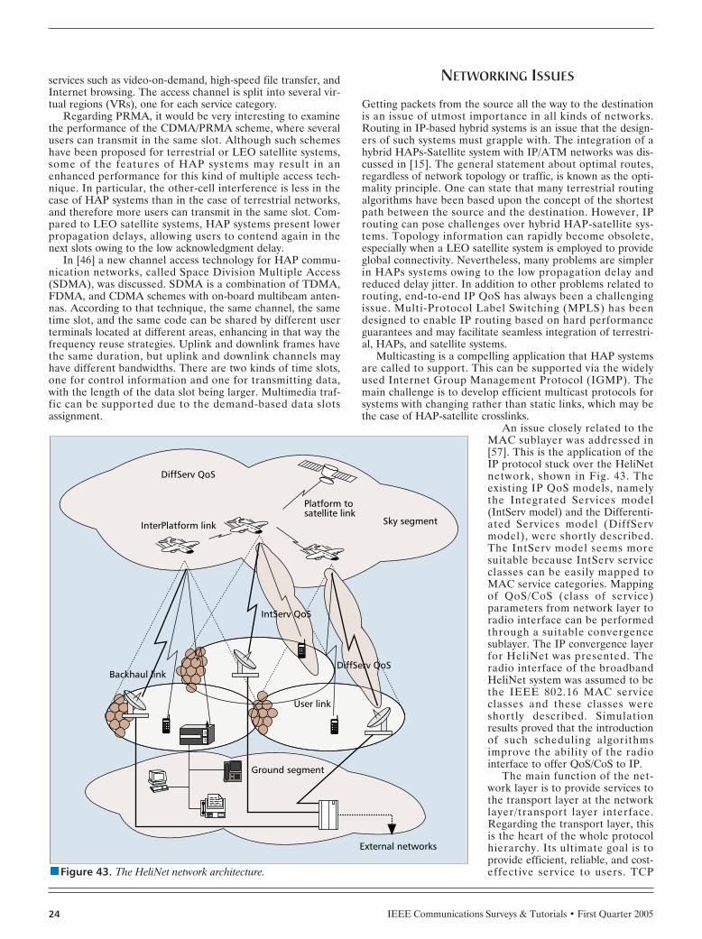
IEEE Communications Surveys & Tutorials • First Quarter 200524
services such as video-on-demand, high-speed file transfer, andInternet browsing. The access channel is split into several vir-tual regions (VRs), one for each service category.
Regarding PRMA, it would be very interesting to examinethe performance of the CDMA/PRMA scheme, where severalusers can transmit in the same slot. Although such schemeshave been proposed for terrestrial or LEO satellite systems,some of the features of HAP systems may result in anenhanced performance for this kind of multiple access tech-nique. In particular, the other-cell interference is less in thecase of HAP systems than in the case of terrestrial networks,and therefore more users can transmit in the same slot. Com-pared to LEO satellite systems, HAP systems present lowerpropagation delays, allowing users to contend again in thenext slots owing to the low acknowledgment delay.
In [46] a new channel access technology for HAP commu-nication networks, called Space Division Multiple Access(SDMA), was discussed. SDMA is a combination of TDMA,FDMA, and CDMA schemes with on-board multibeam anten-nas. According to that technique, the same channel, the sametime slot, and the same code can be shared by different userterminals located at different areas, enhancing in that way thefrequency reuse strategies. Uplink and downlink frames havethe same duration, but uplink and downlink channels mayhave different bandwidths. There are two kinds of time slots,one for control information and one for transmitting data,with the length of the data slot being larger. Multimedia traf-fic can be supported due to the demand-based data slotsassignment.
NETWORKING ISSUES
Getting packets from the source all the way to the destinationis an issue of utmost importance in all kinds of networks.Routing in IP-based hybrid systems is an issue that the design-ers of such systems must grapple with. The integration of ahybrid HAPs-Satellite system with IP/ATM networks was dis-cussed in [15]. The general statement about optimal routes,regardless of network topology or traffic, is known as the opti-mality principle. One can state that many terrestrial routingalgorithms have been based upon the concept of the shortestpath between the source and the destination. However, IProuting can pose challenges over hybrid HAP-satellite sys-tems. Topology information can rapidly become obsolete,especially when a LEO satellite system is employed to provideglobal connectivity. Nevertheless, many problems are simplerin HAPs systems owing to the low propagation delay andreduced delay jitter. In addition to other problems related torouting, end-to-end IP QoS has always been a challengingissue. Multi-Protocol Label Switching (MPLS) has beendesigned to enable IP routing based on hard performanceguarantees and may facilitate seamless integration of terrestri-al, HAPs, and satellite systems.
Multicasting is a compelling application that HAP systemsare called to support. This can be supported via the widelyused Internet Group Management Protocol (IGMP). Themain challenge is to develop efficient multicast protocols forsystems with changing rather than static links, which may bethe case of HAP-satellite crosslinks.
An issue closely related to theMAC sublayer was addressed in[57]. This is the application of theIP protocol stuck over the HeliNetnetwork, shown in Fig. 43. Theexisting IP QoS models, namelythe Integrated Services model(IntServ model) and the Differenti-ated Services model (DiffServmodel), were shortly described.The IntServ model seems moresuitable because IntServ serviceclasses can be easily mapped toMAC service categories. Mappingof QoS/CoS (class of service)parameters from network layer toradio interface can be performedthrough a suitable convergencesublayer. The IP convergence layerfor HeliNet was presented. Theradio interface of the broadbandHeliNet system was assumed to bethe IEEE 802.16 MAC serviceclasses and these classes wereshortly described. Simulationresults proved that the introductionof such scheduling algorithmsimprove the ability of the radiointerface to offer QoS/CoS to IP.
The main function of the net-work layer is to provide services tothe transport layer at the networklayer/transport layer interface.Regarding the transport layer, thisis the heart of the whole protocolhierarchy. Its ultimate goal is toprovide efficient, reliable, and cost-effective service to users. TCPnnnn Figure 43. The HeliNet network architecture.
Ground segment
External networks
Backhaul link
User link
IntServ QoS
DiffServ QoS
Sky segmentInterPlatform link
DiffServ QoS
Platform tosatellite link

IEEE Communications Surveys & Tutorials • First Quarter 2005 25
(Transmission Control Protocol) was designed to provide areliable end-to-end byte stream over an unreliable network.The study in [58] investigated the performance of TCP-basedapplications in a system comprising HAPs/UAVs and a GEOsatellite. HAPs/UAVs can be employed to provide an emer-gency communication infrastructure when cellular base sta-tions and Hot Spots are out of service due to natural hazardsor terrorist attacks. Mobile users on the ground can use theHAPs/UAVs to communicate with each other and access theInternet via the satellite. Two different TCP protocols wereassessed, namely TCP Westwood and TCP New Reno. More-over, a PEP (performance enhancing proxy) scheme was pro-posed, according to which the TCP connection was split at theHAP/UAV. This intermediary performs processing on behalfof TCP endpoints to the greater benefit of performance. Fig-ure 44 illustrates the average throughput for different combi-nations of transport protocols, utilization of the splitmechanism, and various packet error losses (PER) in the linkbetween the mobile user and the HAP/UAV. The combineduse of TCP Westwood and the TCP split presented the bestperformance.
APPLICATIONS AND RELATED PROJECTS
APPLICATIONS
One of the attractive features of HAP systems is their rapiddeployment time. If traffic volumes rise, this temporary net-work can be replaced by a terrestrial wireless or wired net-work. Furthermore, HAPs are very well suited to limited-scopeapplications. For example, they can be used to cover a season-al or a one time event, e.g. the Olympic Games or a musicconcert. They can also be used for providing temporary ser-vices in disaster relief scenarios. For the bulk of emergencymanagement applications, unmanned aircraft hold significantadvantages over airships, mainly due to their immediateresponse time. Permanent communication applications thatcould be provided by HAPs are very wideband Internet access(e.g. 10 Mb/s in downlink and 2 Mb/s in uplink), entertain-ment video and audio, videoconferencing, cellular telephony[17, 48], broadband LMDS services, and access provision todigital networks (i.e. ISDN, Internet).
Different scenarios can be conceived as described in [17].The first scenario employs the HAP as a “backup” base sta-tion covering a wide rural area, partially served by terrestrialbase stations. The role of the HAP is to serve users in the
regions not covered by the terrestrial network. The HAP inthis case acts as an “umbrella.” The second scenario considersthe HAP providing a full-service coverage of a wide ruralarea, where no terrestrial network is active. In this case, theuser density is much higher, imposing some technologicalcomplexity in terms of antenna technology and traffic man-agement. HAPs can be easily integrated with the GSM stan-dard, and their use as GSM base stations for low-user-density,impervious or sea regions, and for emergency applications wasstudied in [48]. Different solutions may be considered. Thefirst is a base station completely on-board; the second is anon-board repeater using GSM frequencies on the link with thereference station, and the third is an on-board repeater usingfrequencies with the reference station not belonging to theGSM band. Regarding the first case, a radio link is needed tocarry the traffic from the aerial platform to the base stationcontroller (BSC) which connects the HAP with the groundnetwork. This radio link can use GSM frequency bands orother bands. Considering power and weight constraints, a BTS(base transceiver station) redesigning is needed. The secondand the third solutions reduce the hardware on-board equip-ment. If GSM frequency bands are used, then the spectralefficiency is reduced while the risk of interference increases. Ifhigher frequency bands are used, smaller antennas are need-ed. Regarding the BTS, it can serve a limited number ofusers. In that article, it was shown that the use of the HeliPlatplatform can be applied to GSM transmission without sub-stantially modifying the standard. Figure 45 shows the attenu-ation curves of a terrestrial and an aerial system as a functionof the distance between mobile terminals and cell centers.When considering UMTS transmission, full compatibility withthe terrestrial standard seriously limits the system perfor-mance, and ad hoc strategies have to be adopted to designeffective cellular stratospheric systems.
The flexibility of the system allows for utilization of HAPsnot only for carrying telecommunication payloads but also forremote sensing: earth observation, satellite navigation applica-tions, pollution monitoring, meteorological measurements,real-time monitoring of seismic or coastal regions and terres-trial structures, traffic monitoring and control, and agriculturesupport. With respect to remote sensing applications, imagesprovided by HAPs are expected to be competitively priced,compared to equivalent images from satellites, due to lowerinfrastructure costs.
In [11, 12] the possible HAP applications were categorizedas high power applications, typically provided from an airship,or as low power applications, provided from an unmannedsolar-powered plane, and were considered to be niche market
n Figure 44. Average throughput over a 230 sec transmission inthe case of a mixed infrastructure comprising HAPs/UAVs and a GEO satellite. (This figure appeared in [58].)
PER (in the link from a mobile user to the HAP/UAV)
0.008200
300
Ave
rage
thr
ough
put
(Kbi
t/s)
0.0060.0040.0020 0.01
400
500
600
700
800
900
Westwood ABSE splitWestwood ABSE end-to-endNew Reno splitNew Reno end-to-end
n Figure 45. Received power dynamics. (This figure appeared in[48].)
Distance of the user from the cell center (km)50 60
-60
-50
Pow
er d
ynam
ics
(dB)
-40
-30
-20
-10
0
4030
Power dynamics of the terrestrial system
Power dynamics of the HELIPLAT-based system
20100

IEEE Communications Surveys & Tutorials • First Quarter 200526
applications. 3G mobile services from HAPs will enable arapid deployment. Over the longer term, HAPs can be used tocover regions with no substantial terrestrial infrastructure, orthey can be used to cover areas subjected to short-term hightraffic demands. HAPs are also suitable for developing coun-tries where there is a lack of existing infrastructure and thegrowth in mobile phone ownership is rapid. Moreover, HAPscan be used to provide broadband wireless applications. Themajor competition is optical fiber. However, for regions withdispersed geography, such as the U.S. and the developingworld, fiber may be less widely available. Regarding lowpower applications, HAPs may provide communications forprimary businesses such as oil, gas and mining industries thatoften operate in remote regions, split across several sites. Abackhaul link could be established via a local fiber backboneor via a satellite. The other low power applications are eventor emergency servicing and the enhancement of communica-tions in developing countries with poor infra-structure.
In [59] the role of HAPs for the provision ofnavigation and positioning services was studied.HAPs can have an active role in Global NavigationSatellite Systems (GNSS) as augmentation systemsto GPS or Galileo, easily performing direction ofarrival estimation thanks to their high position,collecting and broadcasting position information.But the real advantage of HAPs emerges from thefact that they can be used for providing both com-munication and navigation services, with mutualbenefits for both systems, and they can be integrat-ed with terrestrial networks (Fig. 46). By usingHAPs it is possible to broadcast differential cor-rections evaluated by a terrestrial reference sta-tion. One useful technique for differentialcorrection is to use a radio beacon able to transmita satellite-like signal-in-space itself. For this rea-son, it can be considered a terrestrial satellitealways in view and always available to the user,within a certain area. This system is defined as asatellite-like signal transmitter, typically called apseudosatellite or pseudolite. In [60] a system thatsubstitutes the terrestrial pseudosatellite with a
pair of ground control stations with a controlled HAP wasproposed. It was called stratolite. One constraint in the design-ing of such systems is that the position of the HAP should befinely controlled. Except for the accuracy, another benefit ofhybrid positioning systems is that a smart user can select theoptimal set of measurements according to the location. As forthe integration of HAPs and satellites for both communica-tions and navigation, the benefits can lead to cheaperenhanced solutions for infomobility applications. The naviga-tion message can carry structured information, not only neces-sary for positioning, but also additional information on timingand availability of each navigation/communication satellitecommunication channel. A hybrid architecture is depicted inFig. 47.
HAPs/UAVs can also be used for reconnaissance andsurveillance missions, e.g. for transmission of video imagerythrough UAVs and satellites, demonstration of pre-strike tar-geting, and observation of the strikes for near-time bombdamage assessment (Fig. 48). A benefit of using HAPs forthese applications is that they demand limited transmittingpower from user terminals, and therefore this providesenhanced low probability of interception. Considering thehuge size of airships, they might seem unsuitable for militarypurposes. However, their envelope is largely transparent tomicrowaves and they present an extremely low radar cross-section. The potential convergence of UAVs and HAPs formilitary communications was addressed in [61].
RELATED PROJECTS
Recently some projects focusing on aerial vehicles in thestratosphere have been funded. HeliNet was a project basedupon high altitude very long endurance unmanned solar aero-dynamic platforms, funded by the European Commission’s 5th
program. In the framework of the HeliNet project [62], asmall prototype solar powered airframe was partially devel-oped in conjunction with some key elements of power andpropulsion systems. The prototype was based on the design ofan unmanned solar-powered aircraft, named Heliplat. Heliplatwas especially tailored for long endurance operations at analtitude of 17 km, supporting a payload of 100 kg and offeringtotal available power for telecommunications applications of
n Figure 46. A terrestrial cellular network integrated with a cellby an aerial platform (macrocell). (This figure appeared in[59].)
User User
UserTerrestrial
network gateway
User-BTSlink
Aerial BTS
n Figure 47. System architecture for provision of integrated services. (This fig-ure appeared in [59].)
GNSSaugmentationground station
Aerial BTS
Augmentationdata link
GPSGLONASS
Galileo
User-BTSlink
Rangingsignals
Hybrid userterminal
Terrestrialnetwork gateway

IEEE Communications Surveys & Tutorials • First Quarter 2005 27
800 W. Apart from the Heliplat, three prototype applicationswere examined as well, i.e. broadband telecommunication ser-vices, remote sensing, and navigation/localization. Amongexamples of broadband services that can be accommodatedare broadcast TV, video-on-demand, Internet services and e-mail, LAN interconnection and Intranet, bulk file transfer,speech, and video conferencing. Environmental surveillanceapplications involve regional services for agriculture, hydrolo-gy, fire protection, flooding prevention, traffic monitoring anddisaster relief support, pollution monitoring and meteorologi-cal measurement, real-time monitoring of seismic or coastalregions and terrestrial structures, etc. As for navigation ser-vices, the possibility of integrating HeliNet and GNSS2/Galileoto yield additional services was studied. Predictive mainte-nance of the railways is another case where HeliNet couldplay a significant role, either as a complement to the existingsystems or as a stand-alone system.
After the successful completion of the HeliNet project, theinterest in HAPs remained in the European Commission, andin November 2003 the EC started a new research projectnamed CAPANINA [63], which is being partially funded bythe 6th European Union’s Framework initiative. Built on theHeliNet project, Capanina aims at the development of low-cost broadband technology from HAPs to deliver cost effec-tive solutions to users in urban and remote rural areas, or tousers traveling inside high-speed public transport vehicles (e.g.trains). In addition to the identification of appropriate appli-cations and services and associated business models that willhelp to deliver “Broadband to All,” the project intends todevelop aerial links capable of delivering up to 120 Mb/s, astaggering connection 2000 times faster than today’s dial-upconnections and more than 200 times faster than a typical“wired” broadband facility. Users in rural and other impervi-ous areas will benefit from the unique wide-area, high-capaci-ty wireless coverage provided by HAPs. Additionally, use of“smart” roof-top antennas on trains will provide the movinguser with high-speed Internet connectivity. Both mm-waveband and free-space optic communications technologies willbe used. Free-space optic communications have the potentialto deliver very high data rates in clear air conditions, and canbe used for interplatform links and to supplement mm-waveband communications for backhaul traffic. In four years’ time,the project hopes to see commercial services in operationfrom tethered balloons, although the high altitude platform
side may take longer. Three trials are envisaged to take place.The first one started in the summer of 2004 in the UK, mak-ing use of a tethered balloon at an altitude of 300 m. Thescope of this trial will be to demonstrate end-to-end networkconnectivity, broadband access up to 120 Mb/s to a fixed userthrough the 28 GHz band, the use of optical HAP-to-groundlinks, as well as to assess the use of tethered balloons to deliv-er “Broadband for All.” The second trial, which will takeplace in Sweden, will use a free flying stratospheric balloonwith the aim of assessing the atmospheric impacts on opticalcommunications. The third trial, which is actually still underdiscussion, is likely to involve the use of a HAP in order toperform broadband trials.
Another HAP airship project is a Japanese national R&Dproject [3, 8, 46], also referred to as “SkyNet,” commenced in1998 and led by the Science and Technology Agency and theMinistry of Posts and Telecommunications. Further, the Com-munications Research Laboratory (CRL) and the Telecom-munications Advancement Organization of Japan (TAO),which were merged into the National Institute of Informationand Communications Technology (NICT) in 2004, are playinga central role in developing on-board equipment and groundequipment, focusing on the three fields of fixed communica-tions, mobile communications, and broadcasting. This projectaims at producing an integrated network of some 15 airshipsto serve most of Japan, providing interactive broadband com-munication services operating in the 28 GHz band, 3G com-munications, as well as broadcasting and emergency services.Perhaps this project represents the most comprehensive pro-ject on HAPs (spending is 100M€ to date). In the frameworkof this project, prototypes of “DBF” and “MBH” antennaswere developed and demonstrated. Additionally, two proto-type airships have been developed. The first airship, named“Ground-to-Stratosphere (GTS),” measures 47 m, has nopropulsion system, and was successfully used to obtain ther-mal, buoyancy, and position control techniques through theascent to the altitude of about 15 km and descent to a plannedarea in the ocean. The second airship, named “Low-AltitudeStationary (LAS),” measures 68 m and has a propulsion sys-tem. It will be used in order to obtain station-keeping mecha-nisms, as well as to evaluate control models obtained duringthe GTS flight. In June 2002, in collaboration with AeroVi-ronment (a spin-off from NASA), its subsidiary SkyTower andNASA, the world’s first digital high-definition television(HDTV) broadcast transmission from an altitude of 20 kmwas successfully tested. Pathfinder Plus, an unmanned, solar-powered aerial vehicle manufactured by AeroVironment, wasused. This test was followed by an IMT-2000 (3G) mobileapplication that demonstrated video telephony using an off-the-shelf handset sold in Japan. In addition to this trial,another trial was planned for the last quarter of 2004, with thegoal to demonstrate the use of optical links using the LASprototype airship. Currently, basic technologies on solar cellsand fuel cells are under development and are being evaluated.
A similar but much more modest project than “SkyNet” isunderway in Korea, jointly managed by the Electronics andTelecommunications Research Institute (ETRI) and KoreanAerospace Research Institute (KARI). Although the projectwill initially work with a low altitude platform, an airship isplanned for 2008. The platform will provide 3G services aswell as services at 48/47 GHz.
ESA has recently set up some studies related to telecom-munications from HAPs. Initially, the most promising strato-spheric service candidates were selected as broadbandconnectivity, 3G base station service, and digital audio broad-casting (DAB)/DVB-T. Moreover, criteria for the selection ofan appropriate platform were defined and a clear preference
n Figure 48. HAPs for military applications.

IEEE Communications Surveys & Tutorials • First Quarter 200528
was given to solar powered systems. A rough cost estimatewas performed based on analogue experience for manned air-ships and manned airplanes which show a linear relationbetween platform life cycle costs and maximum take-off mass.The ongoing work now concentrates on the development ofsuitable telecommunication system architectures as well as thedesign of a possible European stratospheric platform.
In the U.S., significant interest has been drawn towardHAPs. Recently, the U.S. Missile Defense Agency (MDA)funded project, known as High Altitude Airship (HAA)Advanced Concept Technology Demonstration (ACTD), hasbeen concentrating on the role of unmanned airships inHomeland security. Although the prototype airship will stayaloft for about one month, carrying a 1800 kg payload, futureairships are expected to stay airborne for up to a year andcarry a payload greater than 1800 kg. Initially, airships willgive persistent wide-area surveillance against a full spectrumof air, land, and sea threats, while the next stage of this pro-ject will focus on the development of an airship that could beused in ballistic and cruise missile defense. It is envisionedthat by the end of the decade there will 12 airships around theperimeter of the U.S.
Sanswire Technologies, Inc., a U.S. company, has enteredinto a joint venture with Telesphere Communications, Inc., tolaunch a series of high altitude airships called “Stratellites” inorder to provide high-speed wireless Internet access to theentire continental United States and parts of Canada andMexico. The airships will be held stationary in the strato-sphere at an altitude of 21 km and will be remotely controlledfrom tracking stations on the ground. Each Stratellite isdesigned to stay aloft for up to 12 months, at which time itwould be replaced by a duplicate Stratellite, allowing a seam-less exchange that will prevent outages to subscribers.
The NASA ERAST program (Environmental ResearchAircraft and Sensor Technology) covers several areas ofresearch, and aims toward three types of long endurance plat-forms (Centurion, Alliance I, and Helios). Through fundingsupport from NASA, AeroVironment has developed theunmanned solar-powered aircraft named Helios, which iscapable of continuous flight for up to six months or more ataltitudes greater than 60,000 ft. Helios will provide a Telecom-munications platform from stratosphere, hence the name“SkyTower” that was given to the stratospheric communica-
tions platform. The stratosphericcommunication network will becomprised of airborne segmentsthat will communicate with userterminals and gateway stationsserving as an intermediate inter-face between the aircraft and theexisting Internet and PSTN con-necting systems.
SkyStation Inc. and the HighAltitude Long Operation (HALO)Network project by Angel Tech-nologies Inc. were two U.S. pro-jects aiming to provide digitalbroadband telecommunicationapplications from stratosphericplatforms. SkyStation proposed anetwork based on a lighter than airstratosphere airship. However, theconstraints imposed by airships’drawbacks limited the evolution ofthis project. As far as the HALOnetwork is concerned [18], theHALO-Proteus aircraft was spe-
cially developed a few years ago to operate as a solitary “hub”in a broadband wireless metropolitan network, capable ofserving thousands of users on the ground. A fleet of three air-craft would have been cycling in shifts to achieve continuousservice. The proposed system was manned in order to obtainFederal Aviation Administration (FAA) approval and usedcurrent technology, but the designers hoped that once theconcept was proven the aircraft could be manned by a singlepilot and then eventually be unmanned. However, little hasbeen heard from this venture lately despite the fact that thisnetwork represented generally established technology. Theproposed HALO network is illustrated in Fig. 49. The servicesto be delivered included T1 access, ISDN access, Web brows-ing, high-quality videoconferencing, large file transfers, andEthernet LAN bridging.
Geoscan (UK) Plc is a British-Russian Technology Part-nership that has been developing a network based on the Rus-sian M-55 stratospheric aircraft. The Geoscan Network willprovide broadband fixed wireless services, 3G and 4G ser-vices, and solutions for earth observation and natural disastermonitoring. With the flight time being four or five hours, fouror five aircraft will be flying in turn in order to provide contin-uous service.
Advanced Technologies Group (ATG) of Bedford, U.K.wishes to develop a range of airships. ATG, at one time incollaboration with SkyStation International of the U.S., pro-posed an airship named StratSat, 200 m in length, supportinga communications payload of up to 800 kg. Lindstrand Bal-loons, another U.K. company, has also proposed HAP air-ships. A novel design of HAP comprising several smallerairships joined together in an “airworm” configuration hasbeen developed by the University of Stuttgart. This sausage-like formation aims to provide the lift while avoiding some ofthe structural and aerodynamic problems associated with verylarge airships. As far as unmanned aerial vehicles are con-cerned, General Atomics is a U.S. (San Diego) based manu-facturer of UAVs , while the Global Hawk project of theDefense Advanced Research Projects Agency (DARPA) isconcentrated on the use of UAVs for military applications,such as reconnaissance.
While HAPs have many appealing features, their technologyis still immature. From this perspective, tethered aerostats con-stitute an attractive alternative for the provision of broadband
nnnn Figure 49. The HALO network. (This figure appeared in [18].)
Frequency options: 28 or38 GHz service availability
50 Gb/s throughput capacityTo satellites
1-15HALOTM gateway beams
100-1000subscriber beams
50-75 miles
Coveragecells
Suburban and ruralareas
Urban area

IEEE Communications Surveys & Tutorials • First Quarter 2005 29
services. They may operate at an altitude of 5000 m or more, although there are evident implications for airtraffic safety and their use is highly restricted, with the majorityoperating at much lower altitudes. Platform Wireless Interna-tional Corporation developed an Airborne Relay Communica-tions system (“ARC System”) which was successfullydemonstrated in March 2001. This system uses a 150-ft longtethered aerostat at 15,000 ft. and is able to provide wirelesscommunication services similar to those offered by current ter-restrial cellular systems. In March 2004 the Platform WirelessInternational Corporation was awarded a contract for the designof an ARC System-based national telecommunications networkfor a prominent corporate conglomerate in South Asia. Similarto Platform Wireless International Corporation, SkyLINC Ltd.is an innovative company that is developing its own system,named LIBRA, for the delivery of broadband services from atethered balloon. With the ability to offer expandable, 2 Mb/ssymmetric links to a coverage area of up to 5000 km2, LIBRArepresents a cost-effective alternative to existing terrestrialmasts. Another major application of tethered aerostats issurveillance. Large numbers are deployed along the U.S.-Mexi-can border to detect unauthorized crossings, while aerostats arecurrently deployed by the DoD and by the U.S. for military pur-poses, as part of the “Homeland Security” initiative.
FUTURE PERSPECTIVES
A raft of technologies is currently in use and under develop-ment in order to satisfy the growing demand for high data ratecommunications. Among them, Digital Subscriber Line(xDSL), 2.5G and 3G networks, WLANs, and satellites havebeen widely used for the provision of communication services.However, it has always been a dream of communications engi-neers to develop a wireless system that, while covering a widearea, would provide broadband services with low propagationdelay. With some of their outstanding characteristics, as well astheir capability to provide a variety of services beyond justtelecommunications, HAPs seem to represent a dream cometrue for those communications engineers working on the “idealwireless system.” While possessing many of the advantages ofterrestrial and satellite systems and having the potential to pro-vide broadband communications in a cost effective way, HAPsdo not intend to replace existing technologies, but rather com-plement them. Moreover, HAPs have the potential to deliver awide spectrum of services and applications. Except for broad-band services, they have the potential to deliver 3G-basedcommunications, remote sensing, and navigation applications,while they are also particularly suited to disaster relief applica-tions. It is envisaged that a HAP will be capable of providing acompelling range of these services and applications, presentinga profitable case in this way. However, HAPs are at a similarstage of development as communications satellites were in the1960s, and only recently, some substantive projects have com-menced. Hopefully, in the next few years some of these pro-jects will come to fruition, confirming the usefulness of HAPs,and populating the skies with the first networks of this kind.
REFERENCES[1] G. M. Djuknic, J. Freidenfelds, and Y. Okunev, “Establishing
Wireless Communications Services via High Altitude Platforms:A Concept Whose Time Has Come?,” IEEE Commun. Mag., vol.35, no. 9, Sept. 1997, pp. 128–35.
[2] M. Antonini et al., “Stratospheric Relay: Potentialities of NewSatellite-High Altitude Platforms Integrated Scenarios,” Proc.IEEE Aerospace Conf., 2003, Mar. 8–15, vol. 3, Montana, USA,2003, pp. 1211–19.
[3] R. Miura and M. Suzuki, “Preliminary Flight Test Program onTelecom and Broadcasting Using High Altitude Platform Sta-tions,” Wireless Pers. Commun., An Int’l. J., Kluwer AcademicPublishers, vol. 24, no. 2, Jan. 2003, pp. 341–61.
[4] T. C. Tozer and D. Grace, “High-Altitude Platforms for WirelessCommunications,” IEE Electronics & Commun. Eng. J., vol. 13,no. 3, June 2001, pp. 127–37.
[5] Recommendation ITU-R F.1500, “Preferred Characteristics ofSystems in the FS using High Altitude Platforms Operating inthe Bands 47.2–47.5 GHz and 47.9–48.2 GHz,” Int’l. Telecom-mun. Union, 2000.
[6] D. Grace et al., “Providing Multimedia Communications Ser-vices from High Altitude Platforms,” Int’l. J. Satellite Commun.,Wiley InterScience, vol. 19, no. 6, Nov./Dec. 2001, pp. 559–80.
[7] D. Grace et al., “The European HeliNet Broadband Communi-cations Application — An Update on Progress,” 4th Strato-spheric Platform Systems Wksp. 2003 (SPSW 2003), 26–27 Feb.2003, Shinagawa, Tokyo, Japan.
[8] R. Miura and M. Oodo, “Wireless Communications SystemUsing Stratospheric Platforms — R&D Program on Telecomand Broadcasting System Using High Altitude Platform Sta-tions,” J. Commun. Research Laboratory, CommunicationsResearch Laboratory, Tokyo, Japan, vol. 48, no. 4, 2001, pp.33–48.
[9] V. Milas, M. Koletta, and P. Constantinou, “Interference andCompatibility Studies Between Satellite Systems and Systemsusing High Altitude Platform Stations,” Proc. 1st Int’l. Conf.Advanced Satellite Mobile Systems — ASMS 2003, 10–11 July2003, Frascati, Italy.
[10] B. El-Jabu and S. Steele, “Cellular Communications UsingAerial Platforms,” IEEE Trans. Vehic. Tech., vol. 50, no. 3, May2001, pp. 686–700.
[11] D. Grace, T. C. Tozer, and N. E. Daly, “Communications fromHigh Altitude Platforms — A European perspective,” 2ndStratospheric Platforms System Wksp. 2000 (SPSW 2000),21–22 Sept. 2000, Tokyo, Japan.
[12] T. C. Tozer and D. Grace, “Broadband Service Delivery fromHigh Altitude Platforms,” Communicate 2000 Online Conf.,2–13 October 2000, London, UK.
[13] D. Grace et al., “Broadband Communications from High Alti-tude Platforms — The HeliNet Solution,” in Proc. Wireless Pers.Mobile Conf. (WPMC 2001), vol. 1, 9–12 Sept. 2001, Aalborg,Denmark, pp. 75–80.
[14] T. C. Tozer and D. Grace, “Helinet — The European Solar-Powered HAP Project,” UVS Tech 2001 Conf. & Exhibition,Euro UVS, 6–7 Dec. 2001, Brussels, Belgium (invited paper).
[15] J. Farserotu et al., “Scalable, Hybrid Optical-RF Wireless Com-munication System for Broadband and Multimedia Service toFixed and Mobile Users,” Wireless Pers. Commun., An Int’l. J.,Kluwer Academic Publishers, vol. 24, no. 2, Jan. 2003, pp.327–39.
[16] P. Gace et al., “An Integrated Satellite-HAP-Terrestrial SystemArchitecture: Resources Allocation and Traffic ManagementIssues,” 2004 IEEE 59th Veh. Tech. Conf., VTC2004-Spring,17–19 May 2004, Milan, Italy.
[17] E. Falletti et al., “Integration of a HAP within a TerrestrialUMTS Network: Interference Analysis and Cell Dimensioning,”Wireless Pers. Commun., An Int’l. J., Kluwer Academic Publish-ers, vol. 24, no. 2, Jan. 2003, pp. 291–325.
[18] N. J. Colella, J. N. Martin, and I. F. Akyildiz, “The HALO Network™,”IEEE Commun. Mag., vol. 38, no. 6, June 2000, pp. 142–48.
[19] M. A. Vazquez-Castro, D. Belay-Zelek, and A. Curiese-Guer-rero, “Availability of Systems based on Satellite with SpatialDiversity and HAPs,” IEE Electronics Letters, vol. 38, no. 6, 14Mar. 2002, pp. 286–88.
[20] Jong-Min Park et al., “Technology Development for WirelessCommunications System Using Stratospheric Platform inKorea,” 13th IEEE Int’l. Symp. Pers., Indoor and Mobile RadioCommun., 2002 (PIMRC 2002), Proc., vol. 4, 15–18 Sept. 2002,Lisbon, Portugal, pp. 1596–600.
[21] D. Grace et al., “Communications Performance of High Alti-tude Platform Networks Operating in the mm-Wave Bands,” inProc. 3rd Int’l. Airship Convention and Exhibition, 2000, 1-5July 2000, Friedrichshafen, Germany.

IEEE Communications Surveys & Tutorials • First Quarter 200530
[22] B. T. Ahmed, M. C. Ramon, and L. H. Ariet, “On the Down Link Capacity of High Altitude Platform W-CDMA System,” Proc. IST — Mobile & Wireless Communications Sum-mit 2003, vol. 2, 15–18 June 2003, Aveiro, Portugal, pp.765–68.
[23] D. Grace et al., “Improving Spectrum Utilization for Broad-band Services in mm-Wave Bands using High Altitude Plat-forms,” IEE Conf., “Getting the Most Out of the RadioSpectrum,” 24–25 Oct. 2002, London, UK.
[24] M. Karaliopoulos and F.-N. Pavlidou, “Review of Modeling ofthe Land Mobile Satellite Channel,” IEE Electronics and Com-mun. Eng. J., vol. 11, no. 5, Oct. 1999, pp. 235–48.
[25] C. Oestges and D. Vanhoenacker-Janvier, “Coverage Modeling of High-Altitude Platforms Communication Systems,”IEE Electronics Letters, vol. 37, no. 2, 18 Jan. 2001, pp.119–21.
[26] C. Oestges, “A Stochastic Geometrical Vector Model ofMacro- and Megacellular Communication Channels,” IEEETrans. Vehic. Tech., vol. 51, no. 6, Nov. 2002, pp. 1352–60.
[27] F. Dovis et al., “Small-Scale Fading for High-Altitude Platform(HAP) Propagation Channels,” IEEE JSAC, vol. 20, no. 3, Apr.2002, pp. 641–47.
[28] J. Luis Cuevas-Ruiz and J. A. Delgado-Penin, “Channel Model-ing and Simulation in HAPS Systems,” 5th European WirelessConf. Mobile and Wireless Systems Beyond 3G (EuropeanWireless 2004), 24–27 Feb. 2004, Barcelona, Spain.
[29] M. Pent et al., “HELIPLAT as a GSM Base Station: The Chan-nel Model,” 6th Int’l. Wksp. Digital Signal Processing Tech-niques for Space Applications (DSP ’98), 23–25 Sept. 1998,ESTEC, Noordwijk, The Netherlands.
[30] C. L. Spillard et al., “Effect of Station Antenna Beamwidth onRain Scatter Interference in High-Altitude Platform Links,” IEEElectronics Letters, vol. 38, no. 20, 26 Sept. 2002, pp.1211213.
[31] ITU Recommendations Assembly, “Characteristics of Precipita-tion for Propagation Modeling,” Recommendation ITU-RPN.837-1, 1992-4.
[32] ITU Recommendations Assembly, “Propagation Data and Pre-diction Methods Required for the Design of Earth-SpaceTelecommunication Systems,” Recommendation ITU-R P.618-5,1986-97.
[33] C. L. Spillard, D. Grace, and T. C. Tozer, “The Effect of DelayTolerance on Fade Margin,” Int’l. Wksp. COST Actions 272 and280 Satellite Communications — From Fade Mitigation to Ser-vice Provision, 26–28 May 2003, ESTEC, Noordwijk, TheNetherlands.
[34] J. Bandera et al., “Vertical Variation of Reflectivity and Specif-ic Attenuation in Stratiform and Convective Rainstorms,” IEEElectronics Letters, vol. 35, no. 7, 1 Apr. 1999, pp. 599–600.
[35] J. Bandera et al., “Vertical Path Reduction Factor for High Ele-vation Communication Systems,” IEE Electronics Letters, vol.35, no. 18, 2 Sept. 1999, pp. 1584–85.
[36] J. Thornton et al., “Broadband Communications from a High-Altitude Platform: The European Helinet Program,” IEE Elec-tronics & Commun. Eng. J., vol. 13, no. 3, June 2001,pp.138–44.
[37] D. I. Axiotis and M. E. Theologou, “2 GHz Outdoor to IndoorPropagation at High Elevation Angles,” Proc. 13th IEEE Int’l. Symp. Pers., Indoor and Mobile Radio Commun. 2002(PIMRC 2002), vol. 4, 15–18 Sept., Lisbon, Portugal, pp.901–05.
[38] Y. C. Foo et al., “Other-Cell Interference and Reverse LinkCapacity of High Altitude Platform Station CDMA System,” IEEElectronics Letters, vol. 36, no. 22, 26 Oct. 2000, pp. 1881–82.
[39] N. E. Daly et al., “Prediction of Frequency Reuse Behaviour forHigh Altitude Platforms,” Proc. 3rd Int’l. Airship Conventionand Exhibition, 2000, 1–5 July 2000, Friedrichshafen, Germany.
[40] J. Thornton et al., “Optimizing an Array of Antennas for Cel-lular Coverage from High Altitude Platform,” IEEE Trans. Wire-less Commun., vol. 2, no. 3, May 2003, pp. 484–92.
[41] M. Oodo et al., “Sharing and Compatibility Study BetweenFixed Service using High Altitude Platform Stations (HAPs) andOther Services in the 31/28 GHz Bands,” Wireless Pers. Com-mun., An Int’l. J., Kluwer Academic Publishers, vol. 23, no. 1,Oct. 2002, pp. 3–14.
[42] R. Jin, R. Miura et al., “Modified MRC Beamformer to Sup-press Strong Interferences for On-Board DBF Antenna inHAPs,” IEE Electronics Letters, vol. 38, no. 16, 1 Aug. 2002,pp. 847–48.
[43] K. Siamitros, N. Dimitriou, and R. Tafazolli, “UMTS CoveragePlanning using a High Altitude Platform Station (HAPS),” Proc.5th Int’l. Symp. Wireless Personal Multimedia Commun., 2002,vol. 3, 27–30 Oct. 2002, Sheraton Waikiki, Honolulu, Hawaii,pp. 1157–61.
[44] J. A. Delgado-Penin et al., “Space-Time Coding and Processingto Improve Radio Communication Coverage from High AltitudePlatforms (HAPs) — An Approach,” Data Systems In AerospaceConf. (DASIA’01), 28 May–1 June 2001, Nice, France.
[45] F. Ulloa-Vasquez and J. A. Delgado-Penin, “Performance Sim-ulation in High Altitude Platforms (HAPs) Communications Sys-tems,” Data Systems In Aerospace Conf. (DASIA’01), 13–16May 2002, Dublin, Ireland.
[46] G. Wu, R. Miura, and Y. Hase, “A Broadband Wireless AccessSystem Using Stratospheric Platforms,” Proc. Global Telecom-munications Conf. 2000 (GLOBECOM ’00), vol. 1, 27 Nov.–1Dec., San Francisco, USA, pp. 225–30.
[47] F. Dovis and F. Sellone, “Smart Antenna System Design forAirborne GSM Base-Stations,” Proc. 2000 IEEE Sensor Arrayand Multichannel Sig. Proc. Wksp., 16–17 Mar. 2000, Cam-bridge, UK, 2000., pp. 429–33.
[48] M. Mondin, F. Dovis, and P. Mulassano, “On the Use of HALEPlatforms as GSM Base Stations,” IEEE Pers. Commun., vol. 8,no. 2, Apr. 2001, pp. 37–44.
[49] B.-J. Ku et al., “Degradation Analysis of User Terminal EIRPand G/T due to Station-Keeping Variation of Stratospheric Plat-form,” ETRI J., vol. 22, no. 2, Mar. 2000, ETRI Journal, Elec-tronics and Telecommunications Research Institute, vol.22,no.1, Mar. 2000, pp. 12–19.
[50] B.-J. Ku et al., “Radiation Pattern of Multibeam Array Anten-na with Digital Beamforming for Stratospheric CommunicationSystem: Statistical Simulation,” ETRI J., vol. 24, no. 3, June2002, pp. 197–204.
[51] B.-J. Ku et al., “Design of Linear Array Antenna System forHAPs in S Band,” Proc. 13th IEEE Int’l. Symp. Personal, Indoorand Mobile Radio Communications 2002 (PIMRC 2002), vol. 4,15–18 Sept., Lisbon, Portugal, pp. 1582–85.
[52] J. Thornton, “Dimensioning a Retro-Directive Array for Com-munications via Stratospheric Platform,” ETRI J., Electronicsand Telecommunications Research Institute, vol. 24, no. 2,April 2002, pp. 153–60.
[53] C. He et al., “Dynamic Resource Assignment for StratosphericPlatform Communication System with Multibeam Antenna,”Proc. IEEE Int’l. Conf. Commun. 2001 (ICC 2001), vol. 10,11–14 June 2001, Helsinki, Finland, pp. 3155–59.
[54] D. Grace et al., “Channel Assignment Strategies for a HighAltitude Platform Spot-Beam Architecture,” Proc. 13th IEEEInt’l. Symp. Pers., Indoor and Mobile Radio Commun. 2002(PIMRC 2002) , vol. 4, 1–18 Sept., Lisbon, Portugal, pp.1586–90.
[55] Y. C. Foo, W. L. Lim, and R. Tafazolli, “Centralized DownlinkCall Admission Control for High Altitude Platform StationUMTS with On-Board Power Resource Sharing,” Proc. Vehic.Tech. Conf., IEEE 56th Vehic. Tech. Conf. 2002 (VTC 2002-Fall),vol. 1, 24–28 Sept. 2002, Vancouver, Canada, pp. 549–53.
[56] Y. C. Foo, W. L. Lim, and R. Tafazolli, “Centralized TotalReceived Power-Based Call Admission Control for High AltitudePlatform Station UMTS,” Proc. 13th IEEE Int’l. Symp. Personal,Indoor and Mobile Radio Commun., 2002, vol. 4, 15–18 Sept.,Lisbon, Portugal, pp. 1577–81.
[57] J. Bostic et al., “Delivering IP with QoS/CoS over HeliNet,”Proc. 13th IEEE Int’l. Symp. Pers., Indoor and Mobile RadioCommun. 2002 (PIMRC 2002), vol. 4, 15–18 Sept., Lisbon, Por-tugal, pp. 1591–95.
[58] C. E. Palazzi et al., “Satellite Coverage in Urban Areas usingUnmanned Airborne Vehicles (UAVs),” IEEE 59th Vehic. Tech.Conf. 2004, VTC2004-Spring, 17–19 May 2004, Milan, Italy.
[59] D. Avagnina et al., “Wireless Networks Based on High-Alti-tude Platforms for the Provision of Integrated Navigation/Com-munication Services,” IEEE Commun. Mag., vol. 40, no. 2, Feb.2002, pp. 119–125.

IEEE Communications Surveys & Tutorials • First Quarter 2005 31
[60] F. Dovis, P. Mulassano, and G. Boiero, “System Analysis of aStratolite-Based Local Segment for Galileo,” GNSS Conf. 2001,8–11 May, Seville, Spain.
[61] T. C. Tozer et al., “UAVs and HAPs-Potential Convergence forMilitary Communications,” IEE Colloquium on Military SatelliteCommun., 6 June 2000, London, UK.
[62] http://www.helinet.polito.it (HeliNet Project).[63] http://www.capanina.org (CAPANINA Project).
ADDITIONAL READING[1] D. Grace et al., “LMDS from High Altitude Aeronautical Plat-
forms,” Proc. Global Telecommun. Conf. 1999 (GLOBECOM’99), vol. 5, 5–9 Dec. 1999, Rio de Janeiro, Brazil, pp. 2625–29.
[2] D. Grace, T. C. Tozer, and N. E. Daly, “Communications fromHigh Altitude Platforms — A Complementary or DisruptiveTechnology?,” IEE Colloquium “New Access Network Technolo-gies,” 31 Oct. 2000, UK.
[3] G. Olmo, T. C. Tozer, and D. Grace, “The European HeliNetProject,” in Proc. 3rd Int’l. Airship Convention and Exhibition,2000, 1–5 July 2000, Friedrichshafen, Germany.
[4] T. Tozer, “High Altitude Platforms for Communications Ser-vices,” IEEE-VTS News, vol. 50, no. 4, Dec. 2003, pp. 4–9.
[5] S. Ohmori, Y. Yamao, and N. Nakajima, “The Future Genera-tions of Mobile Communications Based on Broadband AccessMethods,” Wireless Pers. Commun., An Int’l. J, Kluwer Aca-demic Publishers, vol. 17, no. 2–3, June 2001, pp. 175–90.
[6] E. Magli, G. Olmo, and M. A. Spirito, “Study of a RemoteSensing and Localization System on Heliplat,” 6th Int’l. Wksp.Digital Signal Proc. Techniques for Space Applications 1998(DSP ’98), 23–25 Sept. 1998, Noordwijk, The Netherlands.
[7] F. Dovis et al., “HeliNet: A European Project for SustainableEnvironmental Monitoring,” EUROMED-SAFE 1999 Conf.: ASafer Environment for Sustainable Development: The Euro-Mediterranean Cooperation, 27–30 Oct. 1999, Naples, Italy(Invited Paper).
[8] F. Dovis, P. Mulassano, and F. Sellone, “HeliPlat: A HALE Plat-form for Telecommunication and Remote Sensing Applica-tions,” 5th Bayona Wksp. Emerging Tech. in Telecommun., 6–8Sept. 1999, Bayona-Vigo, Spain.
[9] F. Dovis et al., “HeliNet: A Network of UAV-HALE StratosphericPlatforms. System Concepts and Applications to EnvironmentalSurveillance,” Data Systems in Aerospace 2000 (DASIA 2000),22–26 May 2000, Montreal, Canada.
[10] E. Magli et al., “HELINET: An Integrated Network ofUnmanned Aerial Vehicles for Optical Earth Surveillance,”SPIE’s 45th Annual Meeting, Airborne Reconnaissance XXIV,30 July–4 Aug. 2000, San Diego, USA.
[11] E. Falletti, L. Lo Presti, and F. Sellone, “He LOST-HeliplatLocalization System Based on Smart Antennas Technology,” inProc. IEEE 56th Vehic. Tech. Conf. 2002, VTC 2002-Fall, vol. 1,24-28 Sept. 2002, Vancouver, Canada, pp. 275–79.
[12] P. H. Diamandis and N. J. Colella, “Broadband Data Servicesfrom a HALO Aircraft,” in Proc. IEEE Radio and Wireless Conf.1998 (RAWCON ’98), 9–12 Aug. 1998, Colorado Springs, USA,pp. 9–14.
[13] J. N. Martin and N. J. Colella, “Broadband Wireless Communi-cations via Stratospheric HALO Aircraft,” IEEE Military Com-mun. Conf. 1998 (MILCOM 98), vol. 1, 18–21 Oct. 1998,Boston, USA, pp. 45–49.
[14] J. N. Martin and N. J. Colella, “High-Speed Internet Access viaStratospheric HALO Aircraft,” IEEE Emerging Tech. Symp.:Broadband, Wireless Internet Access 2000, 10–11 Apr. 2000,Dallas, Texas USA.
[15] C. A. Robinson, Jr., “High Capacity Aerial Vehicles Aid Wire-less Communications,” Signal, AFCEA’s Official Publication,Apr. 1997, pp. 16–20.
[16] T. Tsujii et al., “Estimation of Residual Tropospheric Delay forHigh-Altitude Vehicles: Towards Precise Positioning of a Strato-spheric Airship,” 13th Int’l. Technical Meeting of the SatelliteDivision of the Institute of Navigation ION GPS 2000, 19–22Sept. 2000, Utah, USA.
[17] T. Tsujii et al., “A Technique for Precise Positioning of HighAltitude Platforms System (HAPS) Using a GPS Ground Refer-ence Network,” 14th Int’l. Technical Meeting of the SatelliteDivision of the Institute of Navigation ION GPS 2001, 11–14Sept. 2001, Utah, USA.
[18] K. T. Nock, M. K. Heun, and K. Aaron, “Global StratosphericBalloon Constellations,” Advances in Space Research, ElsevierScience, vol. 30, no. 5, 2002, pp. 1233–38.
[19] A. Pankine et al., “Stratospheric Satellites for Earth ScienceApplications,” in Proc. IEEE Int’l. Geoscience and Remote Sens-ing Symp., 2002 (IGARSS ’02), vol. 1, 24-28 June 2002, Toron-to, Ontario Canada, pp. 362–64.
[20] M. Gerla and K. Xu, “Integrating Mobile Swarms with Large-Scale Sensor Networks Using Satellites,” IEEE 59th Vehic. Tech.Conf. 2004, VTC2004-Spring, 17–19 May 2004, Milan, Italy.
[21] D. Schawe, C. H. Rohardt, and G. Wichmann, “AerodynamicDesign Assessment of Strato 2C and its Potential forUnmanned High Altitude Airborne Platforms,” Aerospace Sci-ence and Tech., Elsevier Science, vol. 6, no. 1, Jan. 2002, pp.43–51.
[22] E. B. Alberti and J. A. Delgado-Penin, “Effects of Packet For-mat and SBAS Measurements Rate on the Emergency Controlof an UAV,” Data Systems In Aerospace Conf. (DASIA’02),13–16 May, Dublin, Ireland.
[23] http://www.nal.go.jp/npl/spf/0index.html (National AerospaceLaboratory of Japan).
[24] http://www.skytowerglobal.com (Skytower Telecommunica-tions homepage).
[25] http://www.geoscanuk.co.uk (Geoscan Plc).
BIOGRAPHIESSTYLIANOS KARAPANTAZIS [M] ([email protected]) received his diplomain electrical and computer engineering from the Aristotle Universi-ty of Thessaloniki, Greece, in 2003. He is currently workingtoward his Ph.D. degree in the same department. He is involvedin Greek and European projects focused on satellite communica-tions. His research interests include radio resource management insatellite and HAP networks.
FOTINI-NIOVI PAVLIDOU ([email protected]) received the PhD degree inelectrical engineering from the Aristotle University of Thessaloniki,Greece, in 1988 and the diploma in mechanical-electrical engi-neering in 1979 from the same institution. She is currently anassociate professor at the department of electrical and computerengineering at the Aristotle University, teaching in the under-graduate and post-graduate program in the areas of mobile com-munications and telecommunications networks. Her researchinterests are in the field of mobile and personal communications,satellite and HAP communications, multiple access systems, rout-ing and traffic flow in networks, and QoS studies for multimediaapplications over the Internet. She is involved in many nationaland international projects in these areas, and she has chaired theEuropean COST262 Action on Spread Spectrum Techniques. Shehas served as a member of the TPC of many IEEE/IEE conferences.She is a permanent reviewer for many international journals. Shehas published about 80 papers in refereed journals and confer-ences. She is a senior member of IEEE, currently chairing the jointIEEE VTS & AESS Chapter in Greece.
Related Documents