1 Series PV Variable Volume Piston Pumps Catalog HY28-2661-CD/US zp03

Welcome message from author
This document is posted to help you gain knowledge. Please leave a comment to let me know what you think about it! Share it to your friends and learn new things together.
Transcript

Parker Hannifin CorporationHydraulic Pump DivisionMarysville, Ohio USA
Catalog HY28-2661-CD/US Variable Volume Piston Pumps
1
Series PVVariable VolumePiston Pumps
Catalog HY28-2661-CD/US zp03
GR941312
Chassin Conexiones Tel. (461) 615 59 10 Atn Ing. Alberto Hernández Chasin

Parker Hannifin CorporationHydraulic Pump DivisionMarysville, Ohio USA
Variable Volume Piston PumpsCatalog HY28-2661-CD/US
2
Introduction Series PV
Quick Reference Data Chart
DisplacementPump Delivery *Approx. Noise Levels dB(A) Power at Max.
Pumpcc/rev
@ (7 bar) 100 PSI @ Full Flow and 1500 RPM 1800 RPM, Max. OperatingModel
(In3/rev)in LPM (GPM) 70 bar 207 bar 343 bar Displacement & Speed
1200 RPM 1800 RPM (1000 PSI) (3000 PSI) (5000 PSI) 345 bar (5000 PSI) (RPM)
PV016 16 (.98) 19.2 (5.1) 28.8 (7.6) 56 60 68 18.5 kw (24.8 hp) 3000
PV020 20 (1.2) 24.0 (6.3) 36.0 (9.5) 56 60 68 23.4 kw (31.4 hp) 3000
PV023 23 (1.4) 27.6 (7.3) 41.4 (10.9) 56 60 68 25.1 kw (33.6 hp) 3000
PV032 32 (1.9) 38.4 (10.1) 57.6 (15.2) 59 62 69 35.1 kw (47.0 hp) 2800
PV040 40 (2.4) 48.0 (12.7) 72.0 (19.0) 59 62 69 46.5 kw (62.4 hp) 2800
PV046 46 (2.8) 55.2 (14.6) 82.8 (21.9) 59 62 69 50.2 kw (67.3 hp) 2800
PV063 63 (3.8) 75.6 (20.0) 113.4 (30.0) 66 70 74 70.1 kw (94.0 hp) 2800
PV080 80 (4.8) 96.0 (25.4) 144.0 (38.0) 66 70 74 89.2 kw (119.6 hp) 2500
PV092 92 (5.6) 110.4 (29.2) 165.6 (43.8) 66 70 74 136.8 kw (183.5 hp) 2300
PV140 140 (8.5) 168.0 (44.4) 252.1 (66.6) 70 74 76 149.4 kw (200.4 hp) 2800
PV180 180 (10.9) 216.0 (57.1) 324.0 (85.6) 71 75 77 210.0 kw (282.0 hp) 2300
PV270 270 (16.5) 324.0 (85.6) 486.0 (128.4) 77 79 81 298.0 kw (400.0 hp) 1800
* The noise level values are based on anechoic room measurements at a distance of 1 meter in accordance with DIN 45645.

Parker Hannifin CorporationHydraulic Pump DivisionMarysville, Ohio USA
Catalog HY28-2661-CD/US Variable Volume Piston Pumps
3
Introduction Series PV
General Description
All control of the pump outlet flow is achieved by theproper positioning of the swash plate. Control isaccomplished when the bore area forces of the servopiston acting on one end of the swash plate workingagainst the combined effects of the bias spring, andthe rod area forces of the servo piston acting on theother end.
As the shaft in the figure below is rotated by a primemover, it in turn rotates the cylinder barrel. As thecylinder barrel rotates, it drives the pumping pistons ina circular path with the piston slippers supportedhydrostatically against the angled swash plate. In one-half of the revolution, the pumping pistons are forced
away from the port plate drawing in fluid, and in theother half of the revolution, the pumping pistons areforced toward the port plate driving out fluid.
The volume of fluid the pump will displace in onerevolution of the shaft is dependent upon the area ofthe pumping piston, the number of pumping pistonsand the angle of the swash plate. The swash plate isshown at maximum angle and will produce maximumdisplacement. As the swash plate is moved toward avertical position (perpendicular to shaft centerline), thedisplacement will decrease until it reaches the verticalposition and displacement is zero.

Parker Hannifin CorporationHydraulic Pump DivisionMarysville, Ohio USA
Variable Volume Piston PumpsCatalog HY28-2661-CD/US
4
Pressure and Load Sensing Compensators
Load-sensingcompensator withinterface NG6 foraccessoriescode FF1
Shown is load sensing compensator codeFF1 with an NG6 interface on top of the control valve.That allows direct mounting of a pilot valve for pressurecompensation. This version includes the pilot orifice.Due to the interaction of flow and pressure compensationthis package is not the "ideal" control characteristic.The deviation is caused by the pilot valves characteristic.
remote pressurecompensator withinterface NG6 foraccessoriescode FR1
Standard pressure compensator code F*S
The standard pressure compensator adjusts the pumpdisplacement according to the actual need of thesystem in order to keep the pressure constant.As long as the system pressure at outlet port P is lowerthan the set pressure (set as spring preload of thecompensator spring) the working port A of thecompensator valve is connected to the case drain andthe piston area is unloaded. Bias spring and systempressure on the annulus area keep the pump at fulldisplacement.When the system pressure reaches the set pressurethe compensator valve spool connects port P1 to A andbuilds up a pressure at the servo piston resulting in adownstroking of the pump. The displacement of thepump is controlled in order to match the flow requirementof the system.
Remote pressure compensator code FR1
Version FR1 of the remote pressure compensatorprovides on its top side an interface NG6, DIN 24340(CETOP 03 at RP35H, NFPA D03).This interface allows a direct mounting of a pilot valve.Besides manual or electrohydraulic operated valves it isalso possible to mount complete multiple pressurecircuits directly on the compensator body. Parkeroffers a variety of these compensator accessoriesready to install. See page 38 of this catalog.All remote pressure compensators have a factorysetting of 15 bar (217 PSI) differential pressure. Withthis setting, the controlled pressure at the pump outlet is higher than the pressure controlled by the
standard pressurecompensatorcode F*S* = pressure rating
pilot valve.
Parker Hannifin CorporationHydraulic Pump DivisionMarysville, Ohio USA
Catalog HY28-2661-CD/US Variable Volume Piston Pumps
5
Horsepower Compensators
Hydraulic-mechanical horsepower compensatorThe hydraulic-mechanical horsepower compensator consists of a modifiedremote pressure compensator (Code *L*) and a pilot valve. This pilotvalve. This pilot valve is integrated into the pump and is adjusted by a cam sleeve.The cam sleeve has a contour that is designed and machined for the individualdisplacement and the nominal horsepower setting.
At a large displacement the opening pressure (given by the cam sleeve diameter)is lower than at small displacements. This makes the pump compensate alonga constant horsepower (torque) curve.
For all nominal powers of standard electric motors Parker offers a dedicated camsleeve. The exchange of this cam sleeve (e. g.: to change horsepower setting)can easily be done without disassembly of the pump.On top of that an adjustment of the horsepower setting can be done within certainlimits by adjusting the preload of the pilot control cartridge spring . That allowsan adjustment of a constant horsepower setting for other than the nominalspeeds (1500 RPM) or for other horsepowers.The ordering code for the horse power option is as follows:The first digit designates the horsepower setting:
Code B = 5 HP etc. up toCode 3 = 200 HPThe second digit designates the pilot flow source:
Code L internal pilot pressure, remote pressure function.
The third digit designates the possibility to adjust the overriding pressurecompensation:
Code A comes with a top side NG6/D03 interface on the control valve tomount any suitable pilot valve or Parker pump accessories.
Code C includes a pilot valve for manual pressure adjustment. Max. setting:350 bar (5075 PSI).
horse power comp.,pilot flow internalinterface on topcode *LA
horse power comp.,pilot flow internalpressure pilot valveincludedcode *LC
= included
Parker Hannifin CorporationHydraulic Pump DivisionMarysville, Ohio USA
Variable Volume Piston PumpsCatalog HY28-2661-CD/US
6
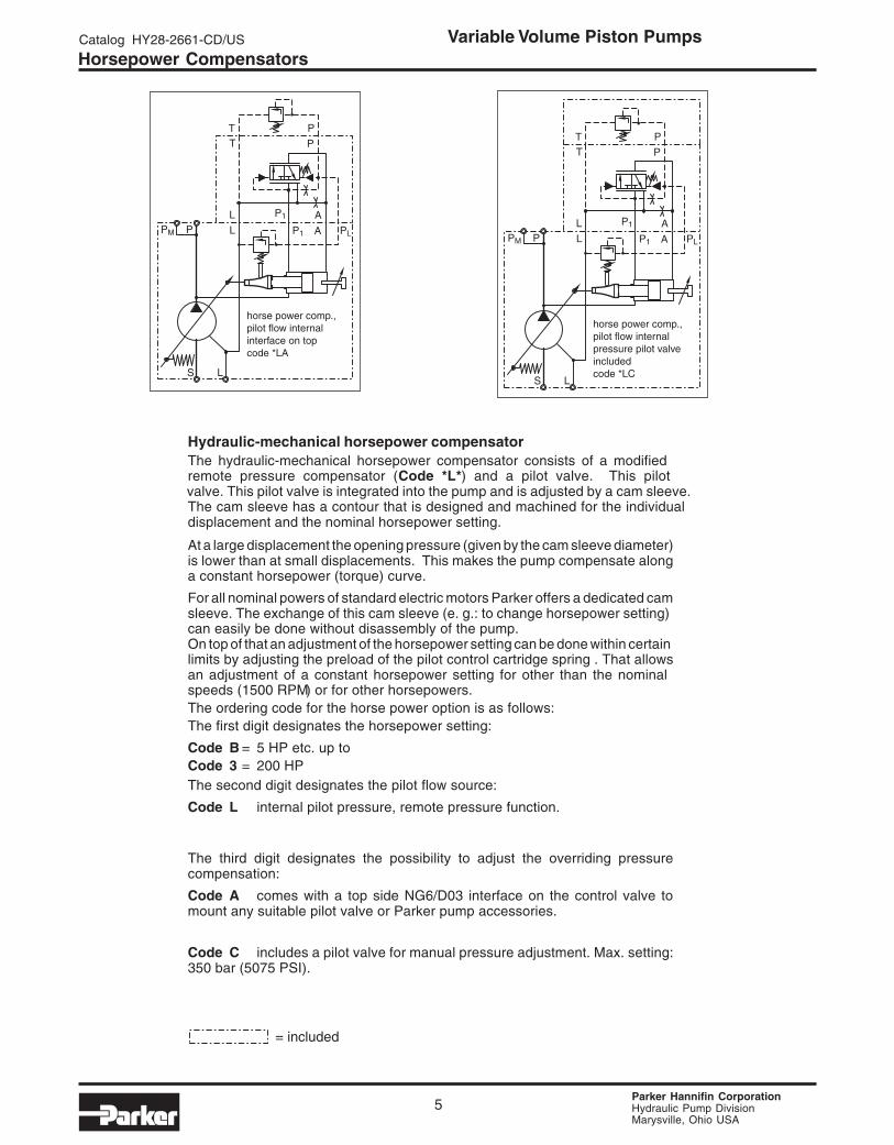
Noise Levels
Typical sound level for single pumps, measured inunechoic chamber according to DIN 45 635, part 1 and26. microphone distance 1 m. speed: n = 1500 min-1.
All data measured with mineral oil viscosity 30 mm²/s(cSt) at 50°C.
0 100 200 3000 1450 2900 4351
barpsi
0 100 200 3000 1450 2900 4351
barpsi
0 100 200 3000 1450 2900 4351
barpsi
0 100 200 3000 1450 2900 4351
barpsi
0 100 200 3000 1450 2900 4351
barpsi
0 100 200 3000 1450 2900 4351
barpsi
71
5
5

Parker Hannifin CorporationHydraulic Pump DivisionMarysville, Ohio USA
Catalog HY28-2661-CD/US Variable Volume Piston Pumps
7
Noise reduction measures
Operating noise of pumps
The normal operating noise of a pump and consequentlythe operating noise of the entire hydraulic system is largelydetermined by where and how the pump is mounted andhow it is connected to the downstream hydraulic system.Also size, style and installation of the hydraulic tubinghave a major influence on the overall noise emitted by ahydraulic system.
Noise reduction measures
Talking about operating noise of a hydraulicpump, primary and secondary pump noisehas to be taken into consideration.
Primary pump noise is caused byvibrations of the pump body due tointernal alternating forces stressing thebody structure.Flexible elements help to prevent pumpbody vibration being transmitted to otherconstruction elements, where possibleamplification may occur. Such elementscan be:
Bell housing with elastic dampening flangewith vulcanized labyrinth (1)
Floating and flexible coupling (2)
Damping rails (3) or silent blocks for mounting theelectric motor or the foot mounting flange
Flexible tube connections (compen-sators) or hoses oninlet, outlet and drain port of the pump.
Exclusive use of gas tight tube fittings for inlet connectionsto avoid ingression of air causing cavitation and excessivenoise.
Secondary pump noise is caused by vibration inducedinto all connected hydraulic components by the flow andpressure pulsation of the pump. This secondary noiseadds typical 7 - 10 dBA to the noise of a pump measuredin the sound chamber according to DIN 45 635. Thereforepipework, its mounting and the mounting of all hydrauliccomponents like pressure filters and control elements hasa major influence to the overall system noise level.Pulsation reduction with precompression volume:the PV is equipped with a new technology for flow ripplereduction. This method reduces the pulsation at the pumpoutlet by 40 - 60 %. That leads to a significant reductionof the overall system noise without additional cost andwithout additional components (silencers etc.). The typicalreduction reaches 2 - 4 dBA. That means: with a pump ofthe PV series the secondary noise adds only some 5 - 7dBA to the pump noise instead of the usually found 7 - 10dBA.Figure 2 compares the measured pulsation of a systemwith 6 pumps of 180 cm³/rev each.
Other measuresSmall diameter tubes do not only cause high flow speeds,turbulences inside the tubes and cavitation in the pump,they also produce noise.Only correctly sized connections of the largest possiblediameter according to the port size of the pump should beused.
Figure 1: components to avoid vibration transfer fromthe pump to the drive/installation and their position in thepower unit (numbers refer to the text on the left)
Figure 2: comparison of the pressure pulsation in asystem with 6 old PV pumps versus the same systemwith 6 PVplus pumps. The pulsation reduction effect ofthe precompression volume is evident.
Last, but not least the connection between pump anddriving motor can be the cause of an unacceptably highnoise emission.Even when the mounting space is limited there aresuitable means and components to reduce the noisesignificantly.The vibration of the pump body, created by high alternatingforces in the rotating group and the pulsation of the outputflow excite every part of the system connected to thepump mechanically or hydraulically .
Parker Hannifin CorporationHydraulic Pump DivisionMarysville, Ohio USA
Variable Volume Piston PumpsCatalog HY28-2661-CD/US
8
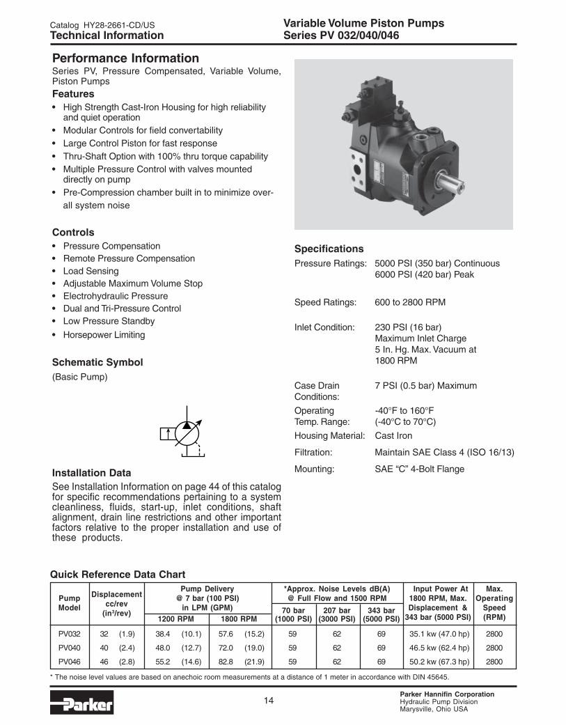
SpecificationsPressure Ratings: 5000 PSI (350 bar) Continuous
6000 PSI (420 bar) Peak
Speed Ratings: 600 to 3000 RPM
Inlet Condition: 230 PSI (16 bar)Maximum Inlet Charge5 In. Hg. Max. Vacuum at1800 RPM
Case Drain 7 PSI (0.5 bar) MaximumConditions:
Operating -40°F to 160°FTemp. Range: (-40°C to 70°C)
Housing Material: Cast Iron
Filtration: Maintain SAE Class 4 (ISO 16/13)
Mounting: SAE “B” 4-Bolt Flange
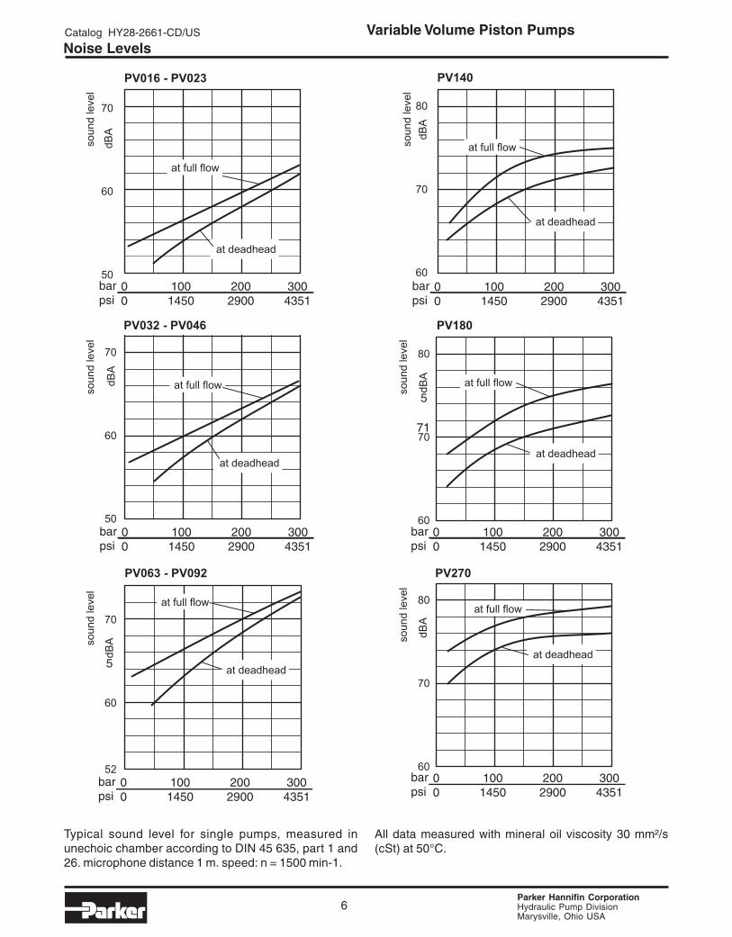
Performance InformationSeries PV, Pressure Compensated, Variable Volume,Piston Pumps
Features• High Strength Cast-Iron Housing for high reliability
and quiet operation• Modular Controls for field convertability• Large Control Piston for fast response• Thru-Shaft Option with 100% thru torque capability• Multiple Pressure Control with valves mounted
directly on pump• Pre-Compression chamber to minimize over-all
system noise
Controls• Pressure Compensation• Remote Pressure Compensation• Load Sensing• Adjustable Maximum Volume Stop• Electrohydraulic Pressure• Dual and Tri-Pressure Control• Low Pressure Standby• Horsepower Limiting
Schematic Symbol(Basic Pump)
Installation DataSee Installation Information on page 44 of this catalogfor specific recommendations pertaining to systemcleanliness, fluids, start-up, inlet conditions, shaftalignment, drain line restrictions and other importantfactors relative to the proper installation and use ofthese products.
Series PV 016/020/023
Quick Reference Data Chart
DisplacementPump Delivery *Approx. Noise Levels dB(A) Input Power At Max.
Pumpcc/rev
@ 7 bar (100 PSI) @ Full Flow and 1500 RPM 1800 RPM, Max. OperatingModel
(in3/rev)in LPM (GPM) 70 bar 207 Bar 343 bar Displacement & Speed
1200 RPM 1800 RPM (1000 PSI) (3000 PSI) (5000 PSI) 343 bar (5000 PSI) (RPM)
PV016 16 (.98) 19.2 (5.1) 28.8 (7.6) 56 60 68 18.5 kw (24.8 hp) 3000
PV020 20 (1.2) 24.0 (6.3) 36.0 (9.5) 56 60 68 23.4 kw (31.4 hp) 3000
PV023 23 (1.4) 27.6 (7.3) 41.4 (10.9) 56 60 68 25.1 kw (33.6 hp) 3000
* The noise level values are based on anechoic room measurements at a distance of 1 meter in accordance with DIN 45645.
Technical Information

Parker Hannifin CorporationHydraulic Pump DivisionMarysville, Ohio USA
Catalog HY28-2661-CD/US Variable Volume Piston Pumps
9
Ordering Information Series PV 016/020/023
Code Pump Variations
1 Standard
9* Reduced Stroke
* Specify in cc/rev.
Code Rotation*
R CW
L CCW
* As viewed fromshaft end.
Code Multiple Pumps
Omit Single
Factory mounted— to rear of another
pump
CodeCM3/REV(In3/rev.)
016 16 (.98)020 20 (1.2)
023 23 (1.4)
PV
Multiple Pump Displace- Rotation Variations Shaft & Threads Thru-Shaft Seals Control Paint MultiplePumps Variable ment Mounting Code Option Options Pumps
Piston
*Drain, gage, and flusing ports.**Mounting and connecting threads
edoCelpitluMspmuP
timO pmuPelgniS
__yrotcaFpmuP
nOdetnuoMraeR
Code Thru-Shaft Option
T1 Thru-Shaft Capable, Single Pump w/Cover
Y7 2 Bolt SAE "AA" Pilot 2.00/SAE "AA" 1/2" Keyed
A7 2 Bolt SAE "A" Pilot 3.25/SAE "A" 9T 16/32 DP
B3 4 Bolt SAE "B" Pilot 4.00/SAE "B" 13T 16/32 DP
J3* 4 Bolt 100mm Pilot/W25x1.5x15x8f Spline DIN 5480
W3 4 Bolt SAE "B" Pilot 4.00/SAE "BB" 15T 16/32 DP
*Must be used with port/thread option 1.
edoC *troP **sdaerhT
1 PPSB cirteM
3 FNU CNU
7 9416OSI CNU
8 9416OSI cirteM
Code Control Options
F • • Standard Pressure CompensatorAdjustment Type
S Screw With NutPressure Range
W 70-350 bar (1015-5075 PSI)H 40-210 bar (580-3050 PSI)D 10-140 bar (150-2050 PSI)
F • • Remote/Load Sense CompensatorControl Port
1 NG6/Cetop3 (D1VW) Pattern *P With PVAC1PC**S** Max Pressure Valve MountedZ NG6 with Pressure Valve Mnt'd**
Compensator Control TypeR Remote PressureF Load Sensing
• L • Horsepower Compensator ControlControl Port
A NG6/Cetop3 (DIVW) Pattern*C NG6 with PVAC1PCS*S** Valve MountedZ NG6 with Pressure Valve Mounted**
Input Horsepower at 1800 RPMB 5.0 (175 in-lb Torque)C 7.5 (262 in-lb Torque)D 10.0 (350 in-lb Torque)E 15.0 (525 in-lb Torque)G 20.0 (700 in-lb Torque)
* Maximum pressure adjustment not included, but recommended. (SeePVAC Section)
* * Valve to be mounted at factory must be ordered as a separate lineitem. Consult factory. See PVAC section for pressure valve options.
edoC tfahS toliP
D )BBEAS(deyeK"1 "B"EAStloB4
E )BBEAS(enilpST51 "B"EAStloB4
K deyeKmm52 mm001tloB4
Lf8x51x5.1x52W
0845NIDenilpSmm001tloB4
Code Painting
Omit No Paint
P Paint
Code Seals
N Nitrile
V Fluorocarbon
E EPRW Nitrile w/PTFE
Shaft Seal
Parker Hannifin CorporationHydraulic Pump DivisionMarysville, Ohio USA
Variable Volume Piston PumpsCatalog HY28-2661-CD/US
10
Technical Information Series PV 016/020/023
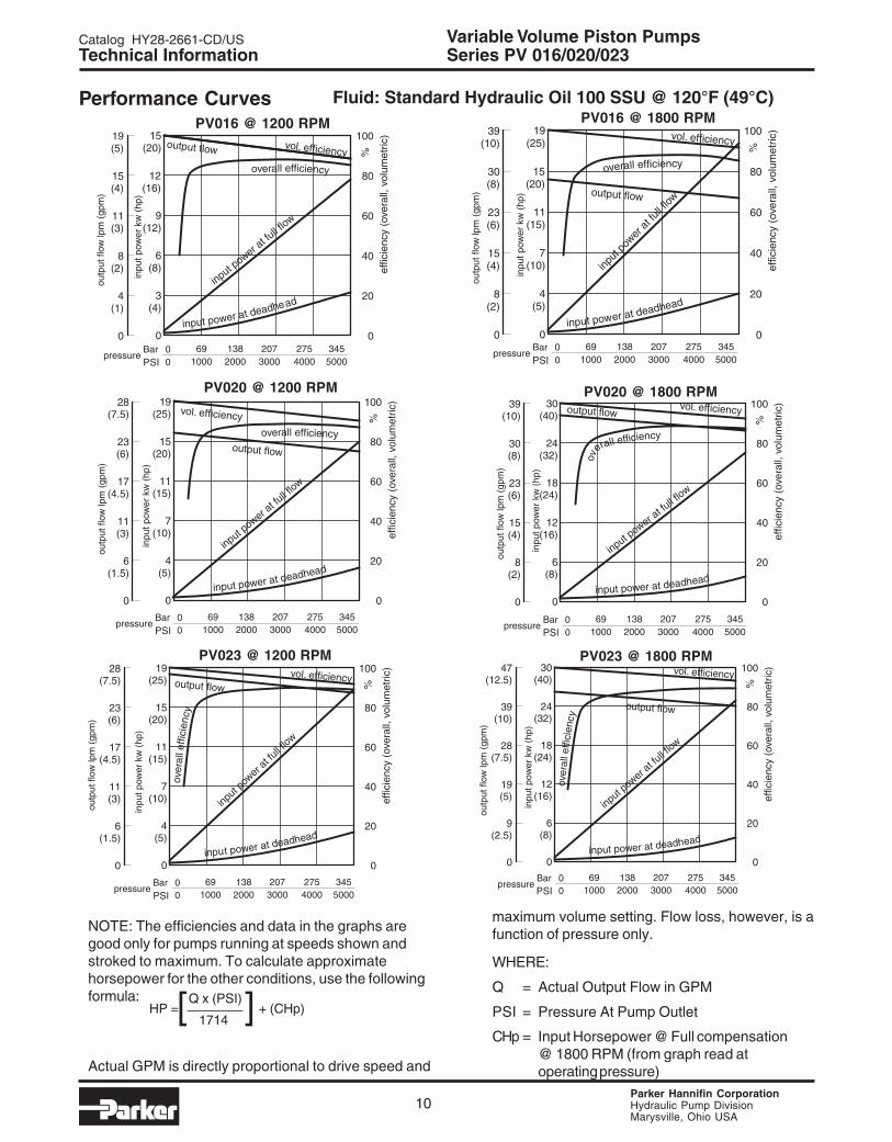
Performance Curves Fluid: Standard Hydraulic Oil 100 SSU @ 120°F (49°C)
NOTE: The efficiencies and data in the graphs aregood only for pumps running at speeds shown andstroked to maximum. To calculate approximatehorsepower for the other conditions, use the followingformula:
Actual GPM is directly proportional to drive speed and
maximum volume setting. Flow loss, however, is afunction of pressure only.
WHERE:
Q = Actual Output Flow in GPM
PSI = Pressure At Pump Outlet
CHp = Input Horsepower @ Full compensation@ 1800 RPM (from graph read atoperating pressure)
[ ]HP = Q x (PSI) + (CHp) 1714
PV016 @ 1200 RPM PV016 @ 1800 RPM
PSIPSI
PV020 @ 1200 RPM PV020 @ 1800 RPM
PSIPSI
PV023 @ 1200 RPM PV023 @ 1800 RPM
PSIPSI

Parker Hannifin CorporationHydraulic Pump DivisionMarysville, Ohio USA
Catalog HY28-2661-CD/US Variable Volume Piston Pumps
11
44.9(1.77)
89.8(3.54)
89.8 (3.54)
44.9 (1.77)
12 (.47)
B
52(2.0)
13(.5)
32(1.3)
197.5 (7.78)
max. 212 (8.35)
16.5 (.65)
16.5 (.65)
132 (5.2)
max. 133 (5.2)
80(3.1)
140(5.5)
22(.87)
170.5 (6.71)162 (6.4)
89 (3.5)
28 (1.1)-0.25 (.009) 48
(1.89)
55(2.17)
15 (.59)
127 (5.0)
A 120(4.7)
94(3.7)
Shaft Option "K"(Ø25mm Ref)8mm x 7mm keyMax Torque = 300 Nm (2655 In-Lbs)
thread M10 - 22 deep
X
View X
flushing port; G 3/8optional M 18 x 1.5; ISO 6149-1(threads options 7 and 8)or 3/4 - 16 UNF (thread option)
gage port G 1/4optional M 12 x 1.5; ISO 6149-1( 7 and 8)7/16 - 20 UNF (threads option 3)threads options
Shown with standard pressure compensator
drain port: G1/2optional M22 x 1.5; ISO 6149-1 (thread options7 and 8) or 7/8-14 UNF (thread option 3)
Optional Drain or Gage Port(see below for sizes)
Ø 25 (.98)
mounting hole for horsepower compensator pilotor displacement feedbackLVDT
"ØC"
Shaft Option "K"
Adjustable Vol. Stop1.5 cc/rev Per Rev.
Series PV 016/020/023Technical Information
edoC A B CØ
E,D "0.4 "73. "0.5
L,K mm001 mm9 mm521

Parker Hannifin CorporationHydraulic Pump DivisionMarysville, Ohio USA
Variable Volume Piston PumpsCatalog HY28-2661-CD/US
12
Series PV 016/020/023Technical Information
58.7(2.31)
30.2(1.19) 23.8
(.94)
50.8(2.00)
Ø 100 (3.9)
43(1.7)
Outlet:Option 3 & 73/4" 4 Bolt Flange3/8-16 UNC-2B ThreadsOption 1 & 819mm 4 Bolt FlangeM10 ThreadsHigh Pressure Series (Code 62)
Inlet:Option 3 & 71-1/4" 4 Bolt Flange7/16-14 UNC-2B ThreadsOption 1 & 832mm 4 Bolt FlangeM10 ThreadsStandard Pressure Series (Code 61)
Shaft Option "L"W25mm x 1.5mm x 15mm x 8fDIN 5480Max Torque = 405 Nm (3584 In-Lbs)
46(1.81)
Ø 101.6 (4.00)
Shaft Option "E"(SAE "BB")15 Teeth 16/32 Pitch30o Involute SplineMax Torque= 300 Nm (2655 In-Lbs)
.250 SAE KEY
25.40 (1.00)25.37 (.999)Ø
50(1.97)
27.94 (1.10)28.19 (1.11)
Shaft Option "D"(SAE "BB")Max Torque= 300 Nm (2655 In-Lbs)
Ø 101.6 (4.00)

Parker Hannifin CorporationHydraulic Pump DivisionMarysville, Ohio USA
Catalog HY28-2661-CD/US Variable Volume Piston Pumps
13
F
CB
DA
197.5 (7.78)225 (8.9)
47.5(1.87)
E
drive output: splined shaft
Thru-Shaft Load LimitationsThe maxiumum allowable torque of the individual shaftmust not be exceeded. For 2-pump combinationsthere is no problem because the PV series offers100% thru torque capabilities. For 3-pumpcombinations or more the limit torque could be reachedor exceeded. Therefore it is necessary to calculatethe torque factor and compare the sum of each pumpstorque factor to the table to make sure it does notexceed the torque limit factor.
Torque
Pump Shaft Limit Factor
D 17700
PV016-023 E 17700
K 17700
L 20130
Required: Sum of all calculated torque factors
must be <torque limit factor.
Torque factor of any pump =
Pressure (bar) x Displacement (cc/rev)
Thru-Shaft Options
Series PV 016/020/023Technical Information
*Coupling included with pump when ordered from Greeneville, TN.
edoC A B C D *E F
7A "52.3Ø "881.4 - 61-"8/3 ENILPSPD23/61T9"A"EAS -
3B "00.4Ø - "635.3 - ENILPSPD23/61T31"B"EAS 31-"2/1
3J mm001Ø - mm44 - ENILPSf8X5.1X52W 01M
3W "00.4Ø - "635.3 - ENILPSPD23/61T51"BB"EAS 31-"2/1
7Y "00.2Ø "052.3 - 81-61/5 DEYEK"2/1"AA"EAS -
Parker Hannifin CorporationHydraulic Pump DivisionMarysville, Ohio USA
Variable Volume Piston PumpsCatalog HY28-2661-CD/US
14
Performance InformationSeries PV, Pressure Compensated, Variable Volume,Piston PumpsFeatures• High Strength Cast-Iron Housing for high reliability
and quiet operation• Modular Controls for field convertability• Large Control Piston for fast response• Thru-Shaft Option with 100% thru torque capability• Multiple Pressure Control with valves mounted
directly on pump• Pre-Compression chamber built in to minimize over- all system noise
Controls• Pressure Compensation• Remote Pressure Compensation• Load Sensing• Adjustable Maximum Volume Stop• Electrohydraulic Pressure• Dual and Tri-Pressure Control• Low Pressure Standby
• Horsepower Limiting
Schematic Symbol(Basic Pump)
Installation DataSee Installation Information on page 44 of this catalogfor specific recommendations pertaining to a systemcleanliness, fluids, start-up, inlet conditions, shaftalignment, drain line restrictions and other importantfactors relative to the proper installation and use ofthese products.
SpecificationsPressure Ratings: 5000 PSI (350 bar) Continuous
6000 PSI (420 bar) Peak
Speed Ratings: 600 to 2800 RPM
Inlet Condition: 230 PSI (16 bar)Maximum Inlet Charge5 In. Hg. Max. Vacuum at1800 RPM
Case Drain 7 PSI (0.5 bar) MaximumConditions:
Operating -40°F to 160°FTemp. Range: (-40°C to 70°C)
Housing Material: Cast Iron
Filtration: Maintain SAE Class 4 (ISO 16/13)
Mounting: SAE “C” 4-Bolt Flange
Technical Information Series PV 032/040/046
Quick Reference Data Chart
DisplacementPump Delivery *Approx. Noise Levels dB(A) Input Power At Max.
Pumpcc/rev
@ 7 bar (100 PSI) @ Full Flow and 1500 RPM 1800 RPM, Max. OperatingModel
(in3/rev)in LPM (GPM) 70 bar 207 bar 343 bar Displacement & Speed
1200 RPM 1800 RPM (1000 PSI) (3000 PSI) (5000 PSI) 343 bar (5000 PSI) (RPM)
PV032 32 (1.9) 38.4 (10.1) 57.6 (15.2) 59 62 69 35.1 kw (47.0 hp) 2800
PV040 40 (2.4) 48.0 (12.7) 72.0 (19.0) 59 62 69 46.5 kw (62.4 hp) 2800
PV046 46 (2.8) 55.2 (14.6) 82.8 (21.9) 59 62 69 50.2 kw (67.3 hp) 2800
* The noise level values are based on anechoic room measurements at a distance of 1 meter in accordance with DIN 45645.
Parker Hannifin CorporationHydraulic Pump DivisionMarysville, Ohio USA
Catalog HY28-2661-CD/US Variable Volume Piston Pumps
15
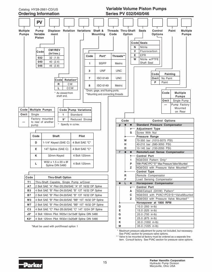
edoC tfahS toliP
D )CEAS(deyeK"4/1-1 "C"EAStloB4
E )CEAS(enilpST41 "C"EAStloB4
K deyeKmm23 mm521tloB4
Lf8x02x5.1x23W
0845NIDenilpSmm521tloB4
Ordering Information Series PV 032/040/046
Code Pump Variations
1 Standard
9* Reduced Stroke
* Specify in cc/rev.
Code Rotation*
R CW
L CCW
* As viewed fromshaft end.
Code Multiple Pumps
Omit Single
Factory mounted— to rear of another
pump
CodeCM3/REV(In3/rev.)
032 32 (1.9)
040 40 (2.4)046 46 (2.8)
*Drain, gage, and flusing ports.**Mounting and connecting threads
*Must be used with port/thread option 1
Code Thru-Shaft Option
T1 Thru-Shaft Capable, Single Pump w/Cover
A7 2 Bolt SAE "A" Pilot Ø3.250/SAE "A" 9T 16/32 DP Spline
B3 4 Bolt SAE "B" Pilot Ø4.00/SAE "B" 13T 16/32 DP Spline
B7 2 Bolt SAE "B" Pilot Ø4.00/SAE "B" 13T 16/32 DP Spline
W3 4 Bolt SAE "B" Pilot Ø4.00/SAE "BB" 15T 16/32 DP Spline
W7 2 Bolt SAE "B" Pilot Ø4.00/SAE "BB" 15T 16/32 DP Spline
C3 4 Bolt SAE "C" Pilot Ø5.00/SAE "C" 14T 12/24 DP Spline
J3* 4 Bolt 100mm Pilot /W25x1.5x15x8f Spline DIN 5480
K3* 4 Bolt 125mm Pilot /W32x1.5x20x8f Spline DIN 5480
edoC *troP **sdaerhT
1 PPSB cirteM
3 FNU CNU
7 9416OSI CNU
8 9416OSI cirteM
PV
Multiple Pump Displace- Rotation Variations Shaft & Threads Thru-Shaft Seals Control Paint MultiplePumps Variable ment Mounting Code Option Options Pumps
Piston
Code Control Options
F • • Standard Pressure CompensatorAdjustment Type
S Screw With NutPressure Range
W 70-350 bar (1015-5075 PSI)H 40-210 bar (580-3050 PSI)D 10-140 bar (150-2050 PSI)
F • • Remote/Load Sense CompensatorControl Port
1 NG6/D03 Pattern Only*P With PVAC1PC**S** Max Pressure Valve MountedZ NG6/D03 with Pressure Valve Mounted**
Control TypeR Remote CompensatorF Load Sensing Compensator
• L • Horsepower CompensatorControl Port
A NG6/Cetop3 (DIVW) Pattern*C NG6/D03 with PVAC1PCS*S**ValveMountedZ NG6/D03 with Pressure Valve Mounted**
Horsepower at 1800 RPMD 10.0 (350 in-lb)E 15.0 (525 in-lb)G 20.0 (700 in-lb)H 25.0 (875 in-lb)K 30.0 (1050 in-lb)M 35.0 (1225 in-lb)
* Maximum pressure adjustment for pump not included, but necessary.See PVAC section for pressure valve options.
* * Valve to be mounted at factory must be ordered as a separate lineitem. Consult factory. See PVAC section for pressure valve options.
Code Painting
Omit No Paint
P Paint
Code Seals
N NitrileV Fluorocarbon
E EPR
W Nitrile w/PTFEShaft Seal
Code MultiplePumps
Omit Single Pump— Pump Factory
Mountedon Rear
Parker Hannifin CorporationHydraulic Pump DivisionMarysville, Ohio USA
Variable Volume Piston PumpsCatalog HY28-2661-CD/US
16
Technical Information Series PV 032/040/046
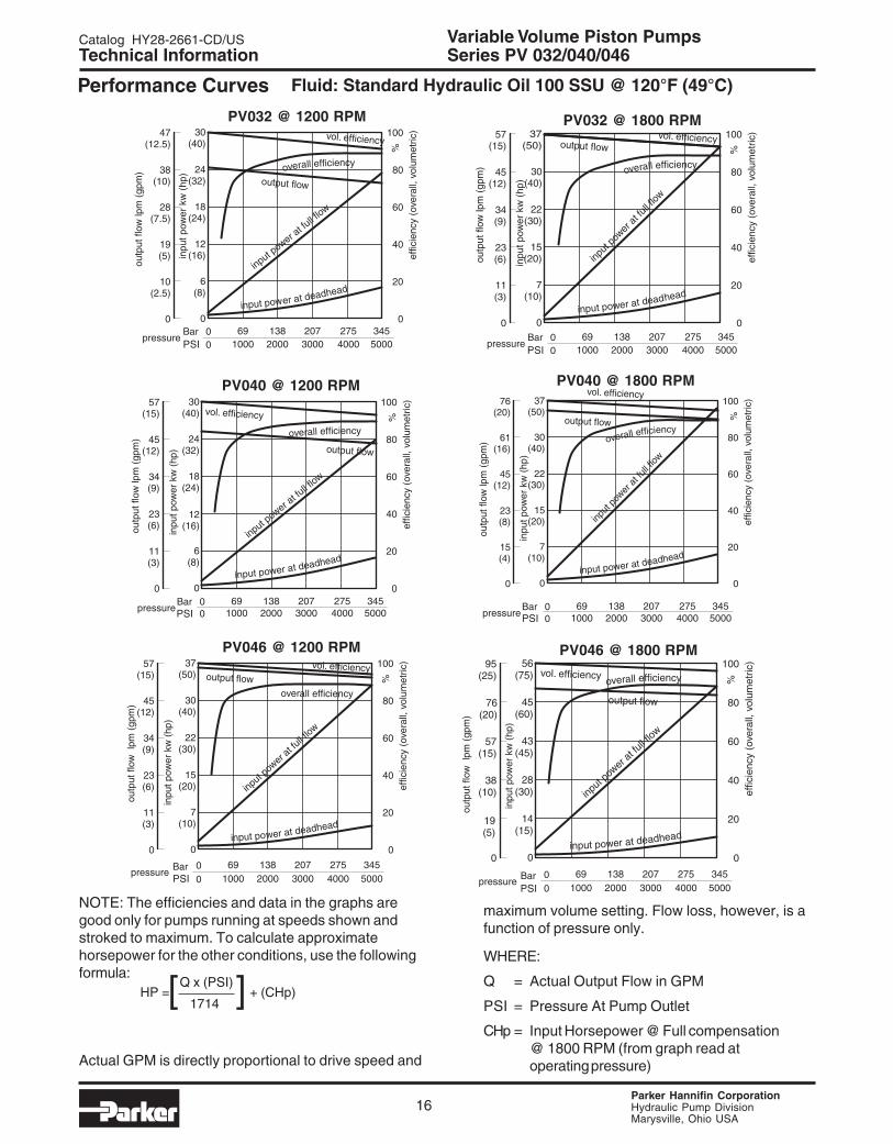
Performance Curves Fluid: Standard Hydraulic Oil 100 SSU @ 120°F (49°C)
NOTE: The efficiencies and data in the graphs aregood only for pumps running at speeds shown andstroked to maximum. To calculate approximatehorsepower for the other conditions, use the followingformula:
Actual GPM is directly proportional to drive speed and
maximum volume setting. Flow loss, however, is afunction of pressure only.
WHERE:
Q = Actual Output Flow in GPM
PSI = Pressure At Pump Outlet
CHp = Input Horsepower @ Full compensation@ 1800 RPM (from graph read atoperating pressure)
[ ]HP = Q x (PSI) + (CHp) 1714
PV032 @ 1200 RPM PV032 @ 1800 RPM
PSIPSI
PV040 @ 1200 RPM PV040 @ 1800 RPM
PSIPSI
PV046 @ 1200 RPM PV046 @ 1800 RPM
PSIPSI

Parker Hannifin CorporationHydraulic Pump DivisionMarysville, Ohio USA
Catalog HY28-2661-CD/US Variable Volume Piston Pumps
17
153(6.0)
107(4.2)
92(3.6)
156(6.1)
max. 130 (5.1)
146 (5.7)
190 (7.5)
197 (7.8)
17 (.7)
60 (2.4) 66 (2.6) 35 (1.4)
-0.25 (.009)
98(3.8)
X
68(2.7)
"A"150(5.9)
22 (.9)
22 (.9)
227 (8.9)
max. 245 (9.6)
15 (.6)
37 (1.4)
View X
flushing port G1/2 optional M 22 x 1.5; ISO 6149-1(threads options 7 and 8)or 7/8 - 14 UNF (threads option 3)
gage port G1/4optional M 12 x 1.5; ISO 6149-1( 7 and 8)7/16 - 20 UNF (threads option 3)threads options
Optional Drain or Gage Port (see below for size)
Shown with standard pressure compensator
mounting hole forhorsepower compensator pilotor displacement feedback LVDT
14 (.6)
114.5(4.51)
57.25 (2.254)
114.5(4.51)
57.25 (2.254)
Shaft Option "K"(Ø32mm ref)10mm x 8mm KeyMax Torque= 570 Nm (5045 in-lbs)
B
drain port G3/4 opt.Optional M27 x 2;ISO 6149-1 (Thread Opt.7 and 8 ) or 1 1/16-12 UNF(Thread Option 3)
Ø32 (1.25)
28 (1.1)
"ØC"
Shaft Option "K"
Adjustable Vol. Stop2.2 cc/rev Per Rev.
Technical Information Series PV 032/040/046
edoC A B CØ
E,D "0.5 "05. "73.6
L,K mm521 mm9 mm061
Parker Hannifin CorporationHydraulic Pump DivisionMarysville, Ohio USA
Variable Volume Piston PumpsCatalog HY28-2661-CD/US
18
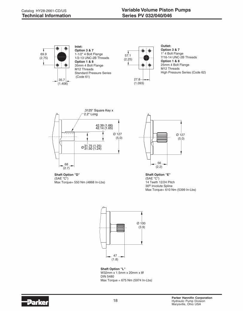
Technical Information Series PV 032/040/046
69.9(2.75)
35.7(1.406)
27.8(1.093)
57.1(2.25)
Ø 100 (3.9)
47(1.8)
Outlet:Option 3 & 71" 4 Bolt Flange7/16-14 UNC-2B ThreadsOption 1 & 825mm 4 Bolt FlangeM12 ThreadsHigh Pressure Series (Code 62)
Inlet:Option 3 & 71-1/2" 4 Bolt Flange1/2-13 UNC-2B ThreadsOption 1 & 835mm 4 Bolt FlangeM12 ThreadsStandard Pressure Series (Code 61)
Shaft Option "L"W32mm x 1.5mm x 20mm x 8fDIN 5480Max Torque = 675 Nm (5974 In-Lbs)
56(2.2)
Ø 127 (5.0)
Shaft Option "E"(SAE "C")14 Teeth 12/24 Pitch30o Involute SplineMax Torque= 610 Nm (5399 In-Lbs)
.3125" Square Key x2.2" Long
31.75 (1.25)31.50 (1.24)Ø
68(2.7)
42.39 (1.66)42.14 (1.65)
Shaft Option "D"(SAE "C")Max Torque= 550 Nm (4868 In-Lbs)
Ø 127 (5.0)
Parker Hannifin CorporationHydraulic Pump DivisionMarysville, Ohio USA
Catalog HY28-2661-CD/US Variable Volume Piston Pumps
19
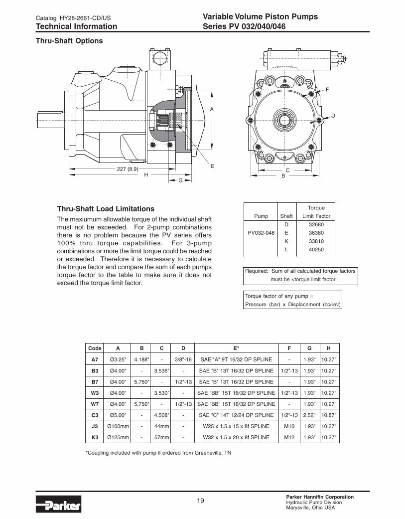
Technical Information Series PV 032/040/046
Required: Sum of all calculated torque factors
must be <torque limit factor.
Torque factor of any pump =
Pressure (bar) x Displacement (cc/rev)
Thru-Shaft Load LimitationsThe maxiumum allowable torque of the individual shaftmust not be exceeded. For 2-pump combinationsthere is no problem because the PV series offers100% thru torque capabilities. For 3-pumpcombinations or more the limit torque could be reachedor exceeded. Therefore it is necessary to calculatethe torque factor and compare the sum of each pumpstorque factor to the table to make sure it does notexceed the torque limit factor.
Torque
Pump Shaft Limit Factor
D 32680
PV032-046 E 36380
K 33810
L 40250
Thru-Shaft Options
C
F
B
DA
227 (8.9)H
G
E
edoC A B C D *E F G H
7A "52.3Ø "881.4 - 61-"8/3 ENILPSPD23/61T9"A"EAS - "39.1 "72.01
3B "00.4Ø - "635.3 - ENILPSPD23/61T31"B"EAS 31-"2/1 "39.1 "72.01
7B "00.4Ø "057.5 - 31-"2/1 ENILPSPD23/61T31"B"EAS - "39.1 "72.01
3W "00.4Ø - "035.3 - ENILPSPD23/61T51"BB"EAS 31-"2/1 "39.1 "72.01
7W "00.4Ø "057.5 - 31-"2/1 ENILPSPD23/61T51"BB"EAS - "39.1 "72.01
3C "00.5Ø - "805.4 - ENILPSPD42/21T41"C"EAS 31-"2/1 "25.2 "78.01
3J mm001Ø - mm44 - ENILPSf8x51x5.1x52W 01M "39.1 "72.01
3K mm521Ø - mm75 - ENILPSf8x02x5.1x23W 21M "39.1 "72.01
*Coupling included with pump if ordered from Greeneville, TN

Parker Hannifin CorporationHydraulic Pump DivisionMarysville, Ohio USA
Variable Volume Piston PumpsCatalog HY28-2661-CD/US
20
Performance InformationSeries PV, Pressure Compensated, Variable Volume,Piston Pumps
Features• High Strength Cast-Iron Housing for high reliability
and quiet operation
• Modular Controls for field convertability
• Large Control Piston for fast response
• Thru-Shaft Option with 100% thru torque capability
• Multiple Pressure Control with valves mounteddirectly on pump
• Pre-Compression chamber to minimize over-
all system noise
Controls• Pressure Compensation
• Remote Pressure Compensation
• Load Sensing
• Adjustable Maximum Volume Stop
• Electrohydraulic Pressure Control
• Dual and Tri-Pressure
• Low Pressure Standby
• Horsepower Limiting
Schematic Symbol(Basic Pump)
Installation DataSee Installation Information on page 44 of this catalogfor specific recommendations pertaining to systemcleanliness, fluids, start-up, inlet conditions, shaftalignment, drain line restrictions and other importantfactors relative to the proper installation and use ofthese products.
Technical Information Series PV 063/080/092
SpecificationsPressure Ratings: 5000 PSI (350 bar) Continuous
6000 PSI (420 bar) Peak
Speed Ratings: 600 to 2800 RPM (PV063)600 to 2500 RPM (PV080)600 to 2300 RPM (PV092)
Inlet Conditions: 230 PSI (16 bar)Maximum Inlet Charge5 In. Hg. Max. Vacuum at1800 RPM
Case Drain 7 PSI (0.5 bar) MaximumConditions:
Operating -40°F to 160°FTemp. Range: (-40°C to 70°C)
Housing Material: Cast Iron
Filtration: Maintain SAE Class 4 (ISO 16/13)
Mounting: SAE “D” 4-Bolt Flange
Quick Reference Data Chart
DisplacementPump Delivery *Approx. Noise Levels dB(A) Input Power At Max.
Pumpcc/rev
@ 7 bar (100 PSI) @ Full Flow and 1500 RPM 1800 RPM, Max. OperatingModel
(in3/rev)in LPM (GPM) 70 bar 207 bar 343 bar Displacement & Speed
1200 RPM 1800 RPM (1000 PSI) (3000 PSI) (5000 PSI) 343 bar (5000 PSI) (RPM)
PV063 63 (3.8) 75.6 (20.0) 113.4 (30.0) 66 70 74 70.1 kw (94.0 hp) 2800
PV080 80 (4.8) 96.0 (25.4) 144.0 (38.0) 66 70 74 89.2 kw (119.6 hp) 2500
PV092 92 (5.6) 110.4 (29.2) 165.6 (43.8) 66 70 74 136.8 kw (183.5 hp) 2300
* The noise level values are based on anechoic room measurements at a distance of 1 meter in accordance with DIN 45645.

Parker Hannifin CorporationHydraulic Pump DivisionMarysville, Ohio USA
Catalog HY28-2661-CD/US Variable Volume Piston Pumps
21
edoC tfahS toliP
D )DEAS(deyeK"4/3-1 "D"EAStloB4
E )CCEAS(enilpST71 "D"EAStloB4
K deyeKmm04 mm061tloB4
Lf8x52x5.1x04W
0845NIDenilpSmm061tloB4
Code Pump Variations
1 Standard
9* Reduced Stroke
* Specify in cc/rev.
Code Rotation*
R CW
L CCW
* As viewed fromshaft end.
Code Multiple Pumps
Omit Single
Factory mounted— to rear of another
pump
CodeCM3/REV(In3/rev.)
063 63 (3.8)
080 80 (4.8)
092 92 (5.6)
*Drain, gage, and flusing ports.**Mounting and connecting threads
*Must be used with port/thread option 1
PV
Multiple Pump Displace- Rotation Variations Shaft & Threads Thru-Shaft Seals Control Paint MultiplePumps Variable ment Mounting Code Option Options Pumps
Piston
Ordering Information Series PV 063/080/092
Code Thru-Shaft Option
T1 Thru-Shaft Capable/ Single Pump w/Cover
A7 2 Bolt SAE "A" Pilot Ø3.250/SAE "A" 9T 16/32 DP Spline
B3 4 Bolt SAE "B" Pilot Ø4.00/SAE "B" 13T 16/32 DP Spline
B7 2 Bolt SAE "B" Pilot Ø4.00/SAE "B" 13T 16/32 DP Spline
C3 4 Bolt SAE "C" Pilot Ø5.00/SAE "C" 14T 12/24 DP Spline
C7 2 Bolt SAE "C" Pilot Ø5.00/SAE "C" 14T 12/24 DP Spline
D3 4 Bolt SAE "D" Pilot Ø6.00/SAE "D" 13T 8/16 DP Spline
J3* 4 Bolt 100mm Pilot /W25x1.5x15x8f Spline DIN 5480
K3* 4 Bolt 125mm Pilot /W32x1.5x20x8f Spline DIN 5480
L3* 4 Bolt 160mm Pilot /W40x1.5x25x8f Spline DIN 5480
W3 4 Bolt SAE "B" Pilot 4.00/SAE "BB" 15T 16/32 DP Spline
W7 2 Bolt SAE "B" Pilot 4.00/SAE "BB" 15T 16/32 DP Spline
Code Control Options
F • • Standard Pressure CompensatorAdjustment Type
S Screw With NutPressure Range
W 70-350 bar (1015-5075 PSI)H 40-210 bar (580-3050 PSI)D 10-140 bar (150-2050 PSI)
F • • Remote/Load Sense CompensatorControl Port
1 NG6/Cetop3 (D1VW) Pattern *P With PVAC1PC**S** Max Pressure Valve MountedZ NG6 with Pressure Valve Mnt'd**
Compensator Control TypeR Remote PressureF Load Sensing
• L • Horsepower Compensator ControlControl Port
A NG6 /Cetop3 (DIVW) Pattern*C NG6 with PVAC1PCS*S** Valve MountedZ NG6 with Pressure Valve Mounted**
Input Horsepower at 1800 RPMG 20.0 (700 in-lb Torque)H 25.0 (875 in-lb Torque)K 30.0 (1050 in-lb Torque)M 35.0 (1225 in-lb Torque)S 50.0 (1750 in-lb Torque)T 60.0 (2100 in-lb Torque)U 75.0 (2625 in-lb Torque)
* Maximum pressure adjustment not included, but recommended. (See
PVAC Section)
* * Valve to be mounted at factory must be ordered as a separate lineitem. Consult factory. See PVAC section for pressure valve options.
edoC *troP **sdaerhT
1 PPSB cirteM
3 FNU CNU
7 9416OSI CNU
8 9416OSI cirteM
Code Painting
Omit No PaintP Paint
Code Seals
N Nitrile
V Fluorocarbon
E EPRW Nitrile w/PTFE
Shaft Seal
Code MultiplePumps
Omit Single Pump— Pump Factory
Mountedon Rear

Parker Hannifin CorporationHydraulic Pump DivisionMarysville, Ohio USA
Variable Volume Piston PumpsCatalog HY28-2661-CD/US
22
Technical Information Series PV 063/080/092
Performance Curves Fluid: Standard Hydraulic Oil 100 SSU @ 120°F (49°C)
NOTE: The efficiencies and data in the graphs aregood only for pumps running at speeds shown andstroked to maximum. To calculate approximatehorsepower for the other conditions, use the followingformula:
Actual GPM is directly proportional to drive speed and
maximum volume setting. Flow loss, however, is afunction of pressure only.
WHERE:
Q = Actual Output Flow in GPM
PSI = Pressure At Pump Outlet
CHp = Input Horsepower @ Full compensation@ 1800 RPM (from graph read atoperating pressure)
[ ]HP = Q x (PSI) + (CHp) 1714
PV063 @ 1200 PRM PV063 @ 1800 PRM
PSIPSI
PV080 @ 1200 RPM PV080 @ 1800 RPM
PSIPSI
PV092 @ 1200 RPM PV092 @ 1800 RPM
PSIPSI
Parker Hannifin CorporationHydraulic Pump DivisionMarysville, Ohio USA
Catalog HY28-2661-CD/US Variable Volume Piston Pumps
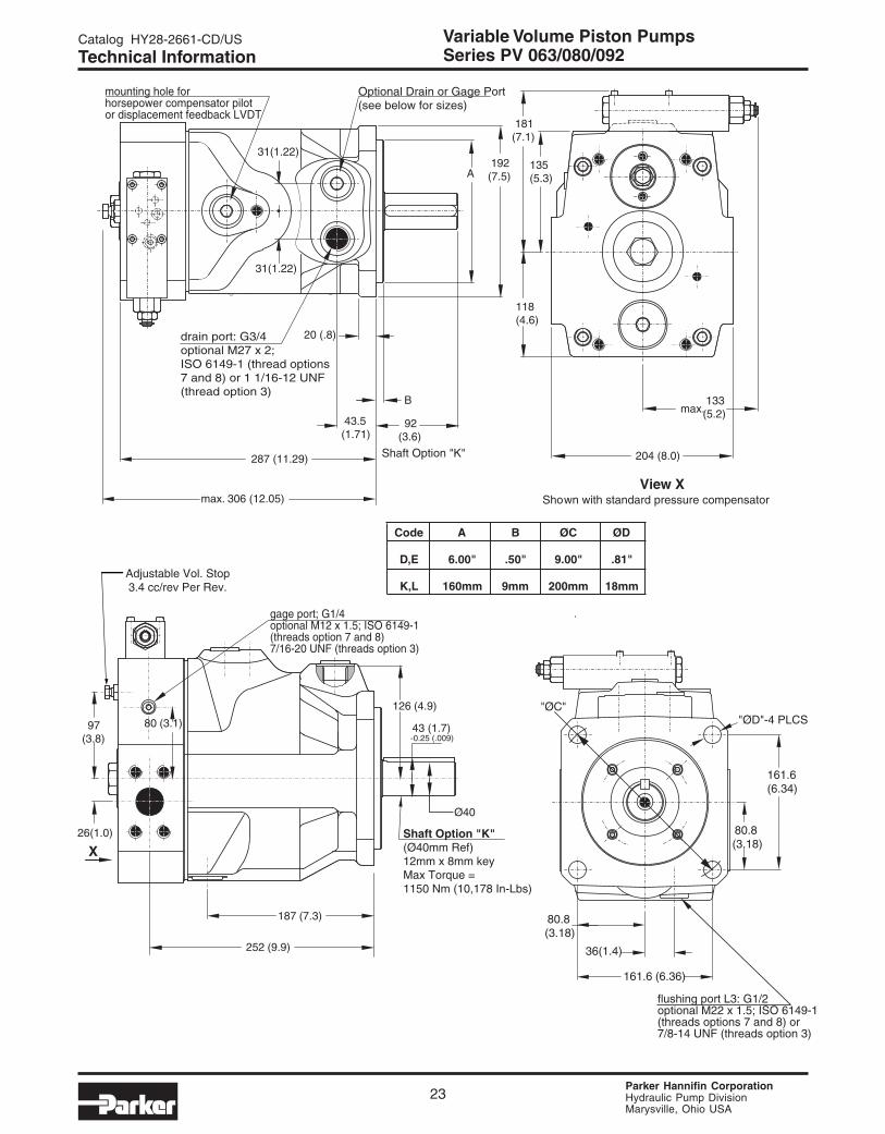
23
flushing port L3: G1/2optional M22 x 1.5; ISO 6149-1(threads options 7 and 8) or7/8-14 UNF (threads option 3)
80.8(3.18)
161.6 (6.36)
80.8 (3.18)
161.6(6.34)
"ØD"-4 PLCS
252 (9.9)
187 (7.3)
97(3.8)
80 (3.1)
26(1.0)
126 (4.9)
36(1.4)
192(7.5)
20 (.8)
43.5(1.71)
B
92(3.6)
287 (11.29)
max. 306 (12.05)
204 (8.0)
118(4.6)
135(5.3)
181(7.1)
31(1.22)
31(1.22)
max. 133(5.2)
43 (1.7)-0.25 (.009)
X
A
View X
gage port; G1/4optional M12 x 1.5; ISO 6149-1(threads option 7 and 8)7/16-20 UNF (threads option 3)
Shown with standard pressure compensator
mounting hole forhorsepower compensator pilotor displacement feedback LVDT
drain port: G3/4optional M27 x 2; ISO 6149-1 (thread options7 and 8) or 1 1/16-12 UNF (thread option 3)
Optional Drain or Gage Port(see below for sizes)
Ø40
Shaft Option "K"(Ø40mm Ref)12mm x 8mm keyMax Torque = 1150 Nm (10,178 In-Lbs)
"ØC"
Shaft Option "K"
Adjustable Vol. Stop3.4 cc/rev Per Rev.
Series PV 063/080/092Technical Information
edoC A B CØ DØ
E,D "00.6 "05. "00.9 "18.
L,K mm061 mm9 mm002 mm81

Parker Hannifin CorporationHydraulic Pump DivisionMarysville, Ohio USA
Variable Volume Piston PumpsCatalog HY28-2661-CD/US
24
Series PV 063/080/092Technical Information
77.8(3.06) 66.6
(2.62)
42.9(1.69)
31.8(1.25)
56(2.2)
Ø 160 (6.3)
Outlet:Option 3 & 71-1/4" 4 Bolt Flange1/2-13 UNC-2B ThreadsOption 1 & 832mm 4 Bolt FlangeM12 ThreadsHigh Pressure Series (Code 62)
Inlet:Option 3 & 72" 4 Bolt Flange1/2-13 UNC-2B ThreadsOption 1 & 850mm 4 Bolt FlangeM12 ThreadsStandard Pressure Series (Code 61)
Shaft Option "L"W40mm x 1.5mm x 25mm x 8fDIN 5480Max Torque = 1400 Nm (12,391In-Lbs)
75(2.9)
Ø 152.4 (6.00)
Shaft Option "E"(SAE "D")13 Tooth, 18/16 DPFlat Root, Side FitMax Torque = 1218 Nm (15,080 In-Lbs)
44.45 (1.75)44.40 (1.74)
.437" Square Key X 3.1" Long
Ø
90(3.5)
49.43 (1.94)49.17 (1.93)
Shaft Option "D"(SAE "D")Max Torque= 1320 Nm (11,683 In-Lbs)
Ø 152.4 (6.00)
Parker Hannifin CorporationHydraulic Pump DivisionMarysville, Ohio USA
Catalog HY28-2661-CD/US Variable Volume Piston Pumps
25
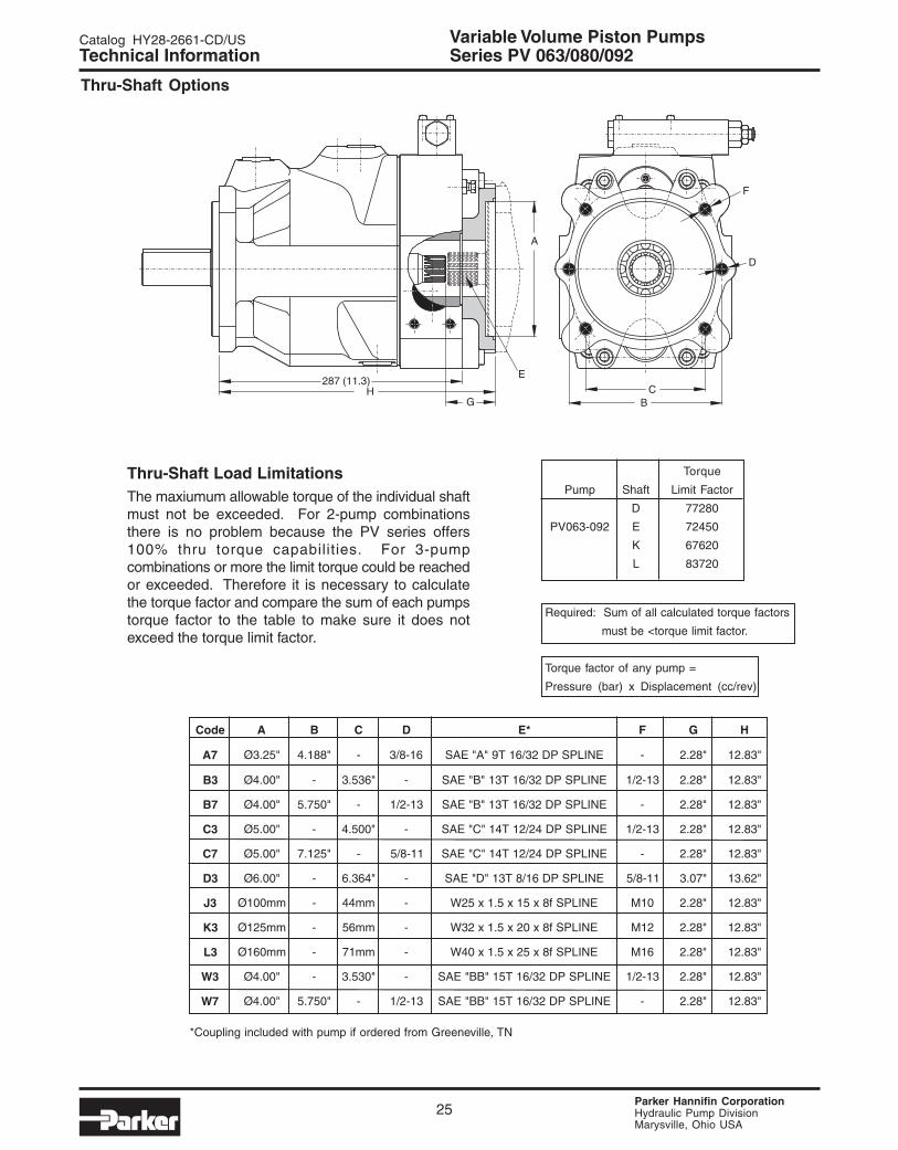
Technical Information Series PV 063/080/092
Required: Sum of all calculated torque factors
must be <torque limit factor.
Torque factor of any pump =
Pressure (bar) x Displacement (cc/rev)
Thru-Shaft Load LimitationsThe maxiumum allowable torque of the individual shaftmust not be exceeded. For 2-pump combinationsthere is no problem because the PV series offers100% thru torque capabilities. For 3-pumpcombinations or more the limit torque could be reachedor exceeded. Therefore it is necessary to calculatethe torque factor and compare the sum of each pumpstorque factor to the table to make sure it does notexceed the torque limit factor.
Torque
Pump Shaft Limit Factor
D 77280
PV063-092 E 72450
K 67620
L 83720
Thru-Shaft Options
287 (11.3)C
F
B
D
A
HG
E
edoC A B C D *E F G H
7A "52.3Ø "881.4 - 61-8/3 ENILPSPD23/61T9"A"EAS - "82.2 "38.21
3B "00.4Ø - "635.3 - ENILPSPD23/61T31"B"EAS 31-2/1 "82.2 "38.21
7B "00.4Ø "057.5 - 31-2/1 ENILPSPD23/61T31"B"EAS - "82.2 "38.21
3C "00.5Ø - "005.4 - ENILPSPD42/21T41"C"EAS 31-2/1 "82.2 "38.21
7C "00.5Ø "521.7 - 11-8/5 ENILPSPD42/21T41"C"EAS - "82.2 "38.21
3D "00.6Ø - "463.6 - ENILPSPD61/8T31"D"EAS 11-8/5 "70.3 "26.31
3J mm001Ø - mm44 - ENILPSf8x51x5.1x52W 01M "82.2 "38.21
3K mm521Ø - mm65 - ENILPSf8x02x5.1x23W 21M "82.2 "38.21
3L mm061Ø - mm17 - ENILPSf8x52x5.1x04W 61M "82.2 "38.21
3W "00.4Ø - "035.3 - ENILPSPD23/61T51"BB"EAS 31-2/1 "82.2 "38.21
7W "00.4Ø "057.5 - 31-2/1 ENILPSPD23/61T51"BB"EAS - "82.2 "38.21
*Coupling included with pump if ordered from Greeneville, TN

Parker Hannifin CorporationHydraulic Pump DivisionMarysville, Ohio USA
Variable Volume Piston PumpsCatalog HY28-2661-CD/US
26
Quick Reference Data Chart
DisplacementPump Delivery *Approx. Noise Levels dB(A) Input Power At Max
Pumpcc/rev
@ 7 bar (100 PSI) @ Full Flow and 1500 RPM 1800 RPM, Max. OperatingModel
(in3/rev)in LPM (GPM) 70 bar 207 bar 343 bar Displacement & Speed
1200 RPM 1800 RPM (1000 PSI) (3000 PSI) (5000 PSI) 343 bar (5000 PSI) (RPM)
PV140 140 (8.59) 168 (44.4) 234 (61.8) 70 74 76 149.4 kw (200.4 hp) 2400
PV180 180 (10.98) 216 (57.1) 324 (85.6) 71 75 77 210.3 kw (282.0 hp) 2200
* The noise level values are based on anechoic room measurements at a distance of 1 meter in accordance with DIN 45645.
Performance InformationSeries PV 140/180 Pressure Compensated, VariableVolume, Piston Pumps
Features• High Strength Cast-Iron Housing for reliable and
quiet operation
• Modular Controls for field convertibility
• Large Control Piston for smooth/fast response
• Multiple Pressure Control with valves mounteddirectly on pump
• Pre-Compression chamber to minimize over-allsystem noise
Controls• Pressure Compensation
• Remote Pressure Compensation
• Load Sensing
• Adjustable Maximum Volume Stop
• Electrohydraulic Pressure
• Dual and Tri-Pressure Control
• Low Pressure Standby
• Horsepower Limiting
Schematic Symbol(Basic Pump)
Installation DataSee Installation Information on page 44 of this catalogfor specific recommendations pertaining to systemcleanliness, fluids, start-up, inlet conditions, shaftalignment, drain line restrictions and other importantfactors relative to the proper installation and use ofthese products.
Technical Information Series PV 140/180
SpecificationsPressure Ratings: 5000 PSI (350 bar) Continuous
6000 PSI (420 bar) Peak
Speed Ratings: 750 to 2400 RPM
Inlet Condition: 725 PSI (50 bar) Maximum3 In-Hg Vacuum at 1500 RPM0 In-Hg Vacuum at 1800 RPM
Case Drain 7 PSI (.5 bar) MaximumConditions:
Operating -40°F to 160°FTemp. Range: (-40°C to 70°C)
Housing Material: Cast Iron
Filtration: Maintain SAE Class 4 (ISO 16/13)
Mounting: SAE “D” 4-Bolt Flange
Parker Hannifin CorporationHydraulic Pump DivisionMarysville, Ohio USA
Catalog HY28-2661-CD/US Variable Volume Piston Pumps
27
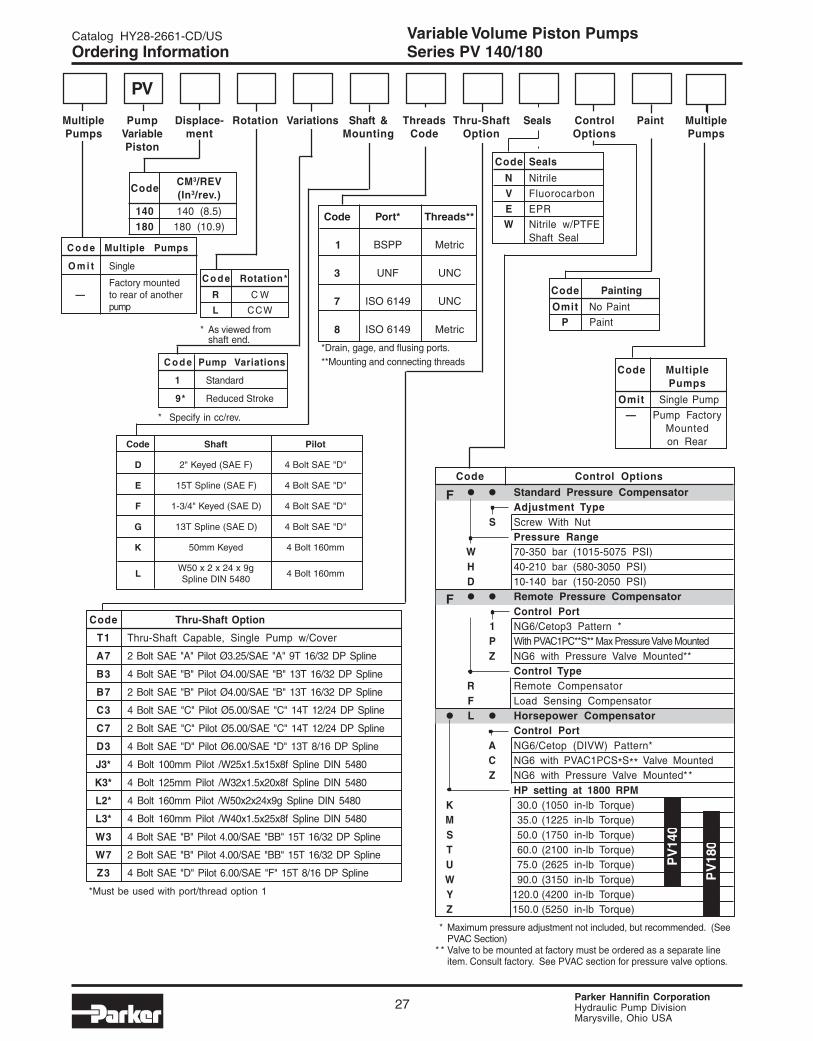
Ordering Information Series PV 140/180
*Must be used with port/thread option 1
C o d e Pump Variations
1 Standard
9* Reduced Stroke
* Specify in cc/rev.
C o d e Rotation*
R C W
L CCW
* As viewed fromshaft end.
C o d e Multiple Pumps
O m i t Single
Factory mounted— to rear of another
pump
CodeCM3/REV(In3/rev.)
140 140 (8.5)
180 180 (10.9)
*Drain, gage, and flusing ports.**Mounting and connecting threads
PV
140
PV
180
PV
Multiple Pump Displace- Rotation Variations Shaft & Threads Thru-Shaft Seals Control Paint MultiplePumps Variable ment Mounting Code Option Options Pumps
Piston
Code Thru-Shaft Option
T1 Thru-Shaft Capable, Single Pump w/Cover
A7 2 Bolt SAE "A" Pilot Ø3.25/SAE "A" 9T 16/32 DP Spline
B3 4 Bolt SAE "B" Pilot Ø4.00/SAE "B" 13T 16/32 DP Spline
B7 2 Bolt SAE "B" Pilot Ø4.00/SAE "B" 13T 16/32 DP Spline
C3 4 Bolt SAE "C" Pilot Ø5.00/SAE "C" 14T 12/24 DP Spline
C7 2 Bolt SAE "C" Pilot Ø5.00/SAE "C" 14T 12/24 DP Spline
D3 4 Bolt SAE "D" Pilot Ø6.00/SAE "D" 13T 8/16 DP Spline
J3* 4 Bolt 100mm Pilot /W25x1.5x15x8f Spline DIN 5480
K3* 4 Bolt 125mm Pilot /W32x1.5x20x8f Spline DIN 5480
L2* 4 Bolt 160mm Pilot /W50x2x24x9g Spline DIN 5480
L3* 4 Bolt 160mm Pilot /W40x1.5x25x8f Spline DIN 5480
W3 4 Bolt SAE "B" Pilot 4.00/SAE "BB" 15T 16/32 DP Spline
W7 2 Bolt SAE "B" Pilot 4.00/SAE "BB" 15T 16/32 DP Spline
Z3 4 Bolt SAE "D" Pilot 6.00/SAE "F" 15T 8/16 DP Spline
Code Control Options
F • • Standard Pressure CompensatorAdjustment Type
S Screw With NutPressure Range
W 70-350 bar (1015-5075 PSI)H 40-210 bar (580-3050 PSI)D 10-140 bar (150-2050 PSI)
F • • Remote Pressure CompensatorControl Port
1 NG6/Cetop3 Pattern *P With PVAC1PC**S** Max Pressure Valve MountedZ NG6 with Pressure Valve Mounted**
Control TypeR Remote CompensatorF Load Sensing Compensator
• L • Horsepower CompensatorControl Port
A NG6/Cetop (DIVW) Pattern*C NG6 with PVAC1PCS*S** Valve MountedZ NG6 with Pressure Valve Mounted**
HP setting at 1800 RPMK 30.0 (1050 in-lb Torque)M 35.0 (1225 in-lb Torque)S 50.0 (1750 in-lb Torque)T 60.0 (2100 in-lb Torque)U 75.0 (2625 in-lb Torque)W 90.0 (3150 in-lb Torque)Y 120.0 (4200 in-lb Torque)Z 150.0 (5250 in-lb Torque)
* Maximum pressure adjustment not included, but recommended. (SeePVAC Section)
* * Valve to be mounted at factory must be ordered as a separate lineitem. Consult factory. See PVAC section for pressure valve options.
edoC *troP **sdaerhT
1 PPSB cirteM
3 FNU CNU
7 9416OSI CNU
8 9416OSI cirteM
edoC tfahS toliP
D )FEAS(deyeK"2 "D"EAStloB4
E )FEAS(enilpST51 "D"EAStloB4
F )DEAS(deyeK"4/3-1 "D"EAStloB4
G )DEAS(enilpST31 "D"EAStloB4
K deyeKmm05 mm061tloB4
Lg9x42x2x05W
0845NIDenilpSmm061tloB4
Code Painting
Omit No PaintP Paint
Code Seals
N Nitrile
V Fluorocarbon
E EPRW Nitrile w/PTFE
Shaft Seal
Code MultiplePumps
Omit Single Pump
— Pump FactoryMountedon Rear

Parker Hannifin CorporationHydraulic Pump DivisionMarysville, Ohio USA
Variable Volume Piston PumpsCatalog HY28-2661-CD/US
28
Performance Curves
Technical Information Series PV 140/180
[ ]HP = Q x (PSI) + (CHp) 1714
NOTE: The efficiencies and data in the graphs aregood only for pumps running at speeds shown andstroked to maximum. To calculate approximatehorsepower for the other conditions, use the followingformula:
Actual GPM is directly proportional to drive speed andmaximum volume setting. Flow loss, however, is afunction of pressure only.
WHERE:
Q = Actual Output Flow in GPM
PSI = Pressure At Pump Outlet
CHp = Input Horsepower @ Full compensation@ 1800 RPM (from graph read atoperating pressure)
Fluid: Standard Hydraulic Oil 100 SSU @ 120°F (49°C)
PV180 @ 1200 RPM PV180 @ 1800 RPM
PSIPSI
PV140 @ 1200 RPM PV140 @ 1800 RPM
PSIPSI
37
75

Parker Hannifin CorporationHydraulic Pump DivisionMarysville, Ohio USA
Catalog HY28-2661-CD/US Variable Volume Piston Pumps
29
80.8(3.18)
161.6 (6.36)
161.6(6.36)
80.8 (3.18)
"ØD"-4 PLCS
204(8.0)
158(6.2)
145(5.7)
200 (7.8)
max. 133 (5.2)
View X
flushing port: G3/4optional M 27 x 2; ISO 6149-1(threads options 7 and 8) or1 1/16-12 UNF (threads option 3)
gage port;G1/4optional M 12 x 1.5; ISO 6149-1( 7 and 8)7/16 - 20 UNF (threads option 3)threads options
293 (11.5)
233 (9.2)
pressure port: 295 (11.6)suction port: 305 (12.0)
105 (4.1)106(4.2)
53.5 (2.1)-0.25 (.009)
98 (3.9)
X
B
92(3.6)
Ø 50 (1.9)
196(7.7)
35 (1.3)
35 (1.3)
350 (13.8)
max. 385 (15.2)
48(1.8)
Optional Drain or Gage Port(see below for size)
drain port; G1optional M33 x 2; ISO 6149-1(threads options 7 and 8)or 1 5/16 - 12 UNF(threads option 3)
40 (1.6)
Shown with standard pressure compensator
mounting hole forhorsepower compensatorpilot or LVDT fordisplacement feedback
20 (.8)
Shaft Option "K"(Ø 50mm Ref.)14mm x 9 mm KeyMax Torque =1900 Nm (16,816 In-Lbs)
A
"ØC"
Shaft Option "K"
Adjustable Vol. Stop8.4 cc/rev Per Rev.
Technical Information Series PV 140/180
edoC A B CØ DØ
E,D "00.6 "05. "00.9 "18.
L,K mm061 mm9 mm002 mm81

Parker Hannifin CorporationHydraulic Pump DivisionMarysville, Ohio USA
Variable Volume Piston PumpsCatalog HY28-2661-CD/US
30
Technical Information Series PV 140/180
31.8(1.25)
66.6(2.62)
88.9(3.50)
50.8(2.00)
Outlet:Option 3 & 71-1/4" 4 Bolt Flange1/2-13 UNC-2B ThreadsOption 1 & 832mm 4 Bolt FlangeM12 ThreadsHigh Pressure Series (Code 62)
Inlet:Option 3 & 72-1/2" 4 Bolt Flange1/2-13 UNC-2B ThreadsOption 1 & 863mm 4 Bolt FlangeM16 ThreadsStandard Pressure Series (Code 61)
88(3.5)
Ø 152.4 (6.00)
Shaft Option "E"(SAE "F")15 Teeth, 8/16 Pitch30o Involute SplineMax Torque = 2680 Nm (23,720 In-Lbs)
50.8(2.00)
1/2" square key X 2.9" LG
Ø
99.4(3.9)
56.39 (2.22)
Shaft Option "D"(SAE "F")Max Torque= 2000 Nm (17,701 In-Lbs)
Ø 44.45 (1.75)-0.05 (.001)
49.3 (1.94) ±0.13 (.005)
75(2.9)
Ø 152.4 (6.00)
key.437 square x2.16" long
Shaft Option "F"(SAE "D")Max Torque= 1320 Nm (11,683 In-Lbs)
75(2.9)
Ø 152.4 (6.00)
Shaft Option "L"W50mm x 2mm x 24mm x 9gDIN 5480Max Torque = 2650 Nm (23,454 In-Lbs)
Ø160 (6.3)
78(3.1)
Shaft Option "G"(SAE "D")13 Teeth 8/16 Pitch30o Involute SplineMax Torque = 1640 Nm (14,515 In-Lbs)
Ø 152.4 (6.00)
Parker Hannifin CorporationHydraulic Pump DivisionMarysville, Ohio USA
Catalog HY28-2661-CD/US Variable Volume Piston Pumps
31
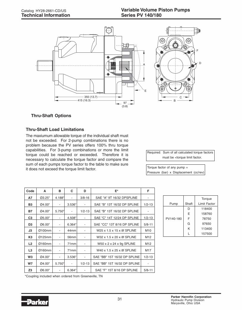
Technical Information Series PV 140/180
Required: Sum of all calculated torque factors
must be <torque limit factor.
Torque factor of any pump =
Pressure (bar) x Displacement (cc/rev)
Torque
Pump Shaft Limit Factor
D 118400
E 158760
PV140-180 F 78750
G 97650
K 113400
L 157500
Thru-Shaft Load LimitationsThe maxiumum allowable torque of the individual shaft mustnot be exceeded. For 2-pump combinations there is noproblem because the PV series offers 100% thru torquecapabilities. For 3-pump combinations or more the limittorque could be reached or exceeded. Therefore it isnecessary to calculate the torque factor and compare thesum of each pumps torque factor to the table to make sureit does not exceed the torque limit factor.
Thru-Shaft Options
350 (13.7)415 (16.3)
97(3.8)
A
BC
F
D
E
*Coupling included when ordered from Greeneville, TN
edoC A B C D *E F
7A "52.3Ø "881.4 - 61-8/3 ENILPSPD23/61T9"A"EAS -
3B "00.4Ø - "635.3 - ENILPSPD23/61T31"B"EAS 31-2/1
7B "00.4Ø "057.5 - 31-2/1 ENILPSPD23/61T31"B"EAS -
3C "00.5Ø - "805.4 - ENILPSPD42/21T41"C"EAS 31-2/1
3D "00.6Ø - "463.6 - ENILPSPD61/8T31"CC"EAS 11-8/5
3J mm001Ø - mm44 - ENILPSf8x51x5.1x52W 01M
3K mm521Ø - mm65 - ENILPSf8x02x5.1x23W 21M
2L mm061Ø - mm17 - ENILPSg9x42x2x05W 21M
3L mm061Ø - mm17 - ENILPSf8x52x5.1x04W 71M
3W "00.4Ø - "635.3 - ENILPSPD23/61T51"BB"EAS 31-2/1
7W "00.4Ø "057.5 - 31-2/1 ENILPSPD23/61T51"BB"EAS -
3Z "00.6Ø - "463.6 - ENILPSPD61/8T51"F"EAS 11-8/5
Parker Hannifin CorporationHydraulic Pump DivisionMarysville, Ohio USA
Variable Volume Piston PumpsCatalog HY28-2661-CD/US
32
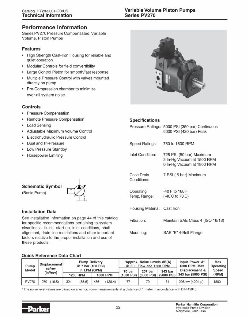
Performance InformationSeries PV270 Pressure Compensated, VariableVolume, Piston Pumps
Features• High Strength Cast-Iron Housing for reliable and
quiet operation
• Modular Controls for field convertibility
• Large Control Piston for smooth/fast response
• Multiple Pressure Control with valves mounteddirectly on pump
• Pre-Compression chamber to minimize
over-all system noise.
Controls• Pressure Compensation
• Remote Pressure Compensation
• Load Sensing
• Adjustable Maximum Volume Control
• Electrohydraulic Pressure Control
• Dual and Tri-Pressure
• Low Pressure Standby
• Horsepower Limiting
Schematic Symbol(Basic Pump)
Installation DataSee Installation Information on page 44 of this catalogfor specific recommendations pertaining to systemcleanliness, fluids, start-up, inlet conditions, shaftalignment, drain line restrictions and other importantfactors relative to the proper installation and use ofthese products.
Technical Information Series PV270
SpecificationsPressure Ratings: 5000 PSI (350 bar) Continuous
6000 PSI (420 bar) Peak
Speed Ratings: 750 to 1800 RPM
Inlet Condition: 725 PSI (50 bar) Maximum3 In-Hg Vacuum at 1500 RPM0 In-Hg Vacuum at 1800 RPM
Case Drain 7 PSI (.5 bar) MaximumConditions:
Operating -40°F to 160°FTemp. Range: (-40°C to 70°C)
Housing Material: Cast Iron
Filtration: Maintain SAE Class 4 (ISO 16/13)
Mounting: SAE “E” 4-Bolt Flange
Quick Reference Data Chart
DisplacementPump Delivery *Approx. Noise Levels dB(A) Input Power At Max
Pumpcc/rev
@ 7 bar (100 PSI) @ Full Flow and 1500 RPM 1800 RPM, Max. OperatingModel
(in3/rev)in LPM (GPM) 70 bar 207 bar 343 bar Displacement & Speed
1200 RPM 1800 RPM (1000 PSI) (3000 PSI) (5000 PSI) 343 bar (5000 PSI) (RPM)
PV270 270 (16.5) 324 (85.6) 486 (128.4) 77 79 81 298 kw (400 hp) 1800
* The noise level values are based on anechoic room measurements at a distance of 1 meter in accordance with DIN 45645.
Parker Hannifin CorporationHydraulic Pump DivisionMarysville, Ohio USA
Catalog HY28-2661-CD/US Variable Volume Piston Pumps
33
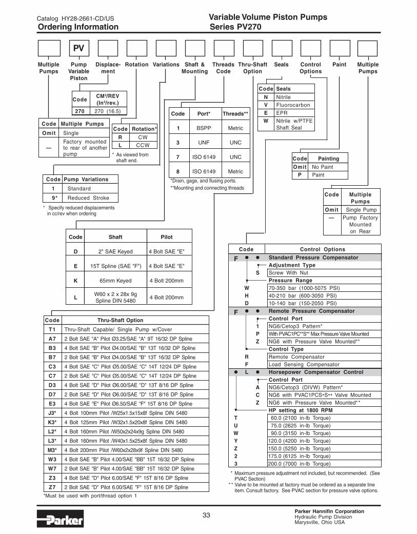
Ordering Information Series PV270
PV
Multiple Pump Displace- Rotation Variations Shaft & Threads Thru-Shaft Seals Control Paint MultiplePumps Variable ment Mounting Code Option Options Pumps
Piston
Code Pump Variations
1 Standard
9* Reduced Stroke
* Specify reduced displacementsin cc/rev when ordering
Code Rotation*
R CW
L CCW
* As viewed fromshaft end.
Code Multiple Pumps
Omit Single
Factory mounted— to rear of another
pump
CodeCM3/REV(In3/rev.)
270 270 (16.5)
*Must be used with port/thread option 1
*Drain, gage, and flusing ports.**Mounting and connecting threads
Code Thru-Shaft Option
T1 Thru-Shaft Capable/ Single Pump w/Cover
A7 2 Bolt SAE "A" Pilot Ø3.25/SAE "A" 9T 16/32 DP Spline
B3 4 Bolt SAE "B" Pilot Ø4.00/SAE "B" 13T 16/32 DP Spline
B7 2 Bolt SAE "B" Pilot Ø4.00/SAE "B" 13T 16/32 DP Spline
C3 4 Bolt SAE "C" Pilot Ø5.00/SAE "C" 14T 12/24 DP Spline
C7 2 Bolt SAE "C" Pilot Ø5.00/SAE "C" 14T 12/24 DP Spline
D3 4 Bolt SAE "D" Pilot Ø6.00/SAE "D" 13T 8/16 DP Spline
D7 2 Bolt SAE "D" Pilot Ø6.00/SAE "D" 13T 8/16 DP Spline
E3 4 Bolt SAE "E" Pilot Ø6.50/SAE "F" 15T 8/16 DP Spline
J3* 4 Bolt 100mm Pilot /W25x1.5x15x8f Spline DIN 5480
K3* 4 Bolt 125mm Pilot /W32x1.5x20x8f Spline DIN 5480
L2* 4 Bolt 160mm Pilot /W50x2x24x9g Spline DIN 5480
L3* 4 Bolt 160mm Pilot /W40x1.5x25x8f Spline DIN 5480
M3* 4 Bolt 200mm Pilot /W60x2x28x9f Spline DIN 5480
W3 4 Bolt SAE "B" Pilot 4.00/SAE "BB" 15T 16/32 DP Spline
W7 2 Bolt SAE "B" Pilot 4.00/SAE "BB" 15T 16/32 DP Spline
Z3 4 Bolt SAE "D" Pilot 6.00/SAE "F" 15T 8/16 DP Spline
Z7 2 Bolt SAE "D" Pilot 6.00/SAE "F" 15T 8/16 DP Spline
Code Control Options
F • • Standard Pressure CompensatorAdjustment Type
S Screw With NutPressure Range
W 70-350 bar (1000-5075 PSI)H 40-210 bar (600-3050 PSI)D 10-140 bar (150-2050 PSI)
F • • Remote Pressure CompensatorControl Port
1 NG6/Cetop3 Pattern*P With PVAC1PC**S** Max Pressure Valve MountedZ NG6 with Pressure Valve Mounted**
Control TypeR Remote CompensatorF Load Sensing Compensator
• L • Horsepower Compensator ControlControl Port
A NG6/Cetop3 (DIVW) Pattern*C NG6 with PVAC1PCS*S** Valve MountedZ NG6 with Pressure Valve Mounted**
HP setting at 1800 RPMT 60.0 (2100 in-lb Torque)U 75.0 (2625 in-lb Torque)W 90.0 (3150 in-lb Torque)Y 120.0 (4200 in-lb Torque)Z 150.0 (5250 in-lb Torque)2 175.0 (6125 in-lb Torque)3 200.0 (7000 in-lb Torque)
* Maximum pressure adjustment not included, but recommended. (SeePVAC Section)
* * Valve to be mounted at factory must be ordered as a separate lineitem. Consult factory. See PVAC section for pressure valve options.
edoC *troP **sdaerhT
1 PPSB cirteM
3 FNU CNU
7 9416OSI CNU
8 9416OSI cirteM
edoC tfahS toliP
D deyeKEAS"2 "E"EAStloB4
E )"F"EAS(enilpST51 "E"EAStloB4
K deyeKmm56 mm002tloB4
Lg9x82x2x06W0845NIDenilpS
mm002tloB4
Code Painting
Omit No PaintP Paint
Code Seals
N NitrileV Fluorocarbon
E EPR
W Nitrile w/PTFEShaft Seal
Code MultiplePumps
Omit Single Pump— Pump Factory
Mountedon Rear

Parker Hannifin CorporationHydraulic Pump DivisionMarysville, Ohio USA
Variable Volume Piston PumpsCatalog HY28-2661-CD/US
34
Performance Curves
Technical Information Series PV270
[ ]HP = Q x (PSI) + (CHp) 1714
NOTE: The efficiencies and data in the graphs aregood only for pumps running at speeds shown andstroked to maximum. To calculate approximatehorsepower for the other conditions, use the followingformula:
Actual GPM is directly proportional to drive speed andmaximum volume setting. Flow loss, however, is afunction of pressure only.
WHERE:
Q = Actual Output Flow in GPM
PSI = Pressure At Pump Outlet
CHp = Input Horsepower @ Full compensation@ 1800 RPM (from graph read atoperating pressure)
Fluid: Standard Hydraulic Oil 100 SSU @ 120°F (49°C)
PV270 @ 1200 RPM PV270 @ 1800 RPM
PSIPSI

Parker Hannifin CorporationHydraulic Pump DivisionMarysville, Ohio USA
Catalog HY28-2661-CD/US Variable Volume Piston Pumps
35
A 45 (1.8)
45 (1.8)
25 (.9)
B
60 (2.4)
115(4.5)
max. 510 (20.1)
69 (2.7)-0.25 (.009)
172 (6.8)128(5.0)
113(4.4)
306 (12.0)
378 (14.8)
403 (15.8)
184(7.2)
230(9.1)
176(6.9)
250 (9.8)
265 (10.4)
gage port; G1/4optional M 12 x 1.5; ISO 6149-1 ( 7 and 8)or 7/16 - 20 UNF ( 3)
threads optionsthreads option
flushing port; G 3/4optional M 27 x 2; ISO 6149-1( 7 and 8)or 1 1/16 - 12 UNF( 3)
threads options
threads option
view X
X
50(1.9)
472.5 (18.6)
mounting hole for horse-power pilot or LVDT fordisplacement feedback
Ø 65 (2.5)
optional draing or gage port(see below for size)
224.5(8.84)
112.25(4.419)
112.25(4.419)
224.5(8.84)
"ØD"- 4 PLCS
Shaft Option "K"(Ø65mm Ref)18mm x 11mm keyMax Torque = 2850 Nm (25,225 In-Lbs)
Shown with standard pressure compensator
drain port; G 1 1/4optional M42 x 2; ISO 6149-1(threads option 7 and 8)or 1 5/8-12 UNF (threads option 3)
"ØC"
Shaft Option "K"
Adjustable Vol. Stop10.2 cc/rev Per Rev.
Technical Information Series PV270
edoC A B CØ DØ
E,D "05.6 "05. "05.21 "18.
L,K mm002 mm9 mm052 mm22
Parker Hannifin CorporationHydraulic Pump DivisionMarysville, Ohio USA
Variable Volume Piston PumpsCatalog HY28-2661-CD/US
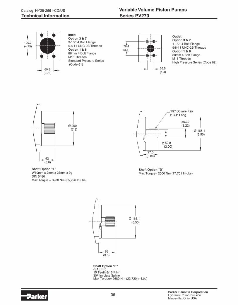
36
Technical Information Series PV270
Ø 200 (7.9)
92(3.6)
69.8(2.75)
120.7(4.75)
36.5(1.4)
79.4(3.1)
Outlet:Option 3 & 71-1/2" 4 Bolt Flange5/8-11 UNC-2B ThreadsOption 1 & 838mm 4 Bolt FlangeM16 ThreadsHigh Pressure Series (Code 62)
Inlet:Option 3 & 73-1/2" 4 Bolt Flange5.8-11 UNC-2B ThreadsOption 1 & 888mm 4 Bolt FlangeM16 ThreadsStandard Pressure Series (Code 61)
Shaft Option "L"W60mm x 2mm x 28mm x 9gDIN 5480Max Torque = 3980 Nm (35,226 In-Lbs)
88(3.5)
Ø 165.1 (6.50)
Shaft Option "E"(SAE FF)15 Teeth 8/16 Pitch30o Involute SplineMax Torque= 2680 Nm (23,720 In-Lbs)
1/2" Square Key 2 3/4" Long
50.8 (2.00)
Ø
56.39 (2.22)
Shaft Option "D"Max Torque= 2000 Nm (17,701 In-Lbs)
97.5(3.84)
Ø 165.1 (6.50)

Parker Hannifin CorporationHydraulic Pump DivisionMarysville, Ohio USA
Catalog HY28-2661-CD/US Variable Volume Piston Pumps
37
Required: Sum of all calculated torque factors
must be <torque limit factor.
Torque factor of any pump =
Pressure x Displacement (cc/rev) bar
Torque
Pump Shaft Limit Factor
D 119,000
PV270 E 159,700
K 170,100
L 236,250
Thru-Shaft Load LimitationsThe maxiumum allowable torque of the individual shaftmust not be exceeded. For 2-pump combinationsthere is no problem because the PV series offers100% thru torque capabilities. For 3-pumpcombinations or more the limit torque could bereached or exceeded. Therefore it is necessary tocalculate the torque factor and compare the sum ofeach pumps torque factor to the table to make sureit does not exceed the torque limit factor.
Technical Information Series PV270
edoC A B C D *E F
7A "52.3Ø "881.4 - 61-8/3 ENILPSPD23/61T9"A"EAS -
3B "00.4Ø - "635.3 - ENILPSPD23/61T31"B"EAS 31-2/1
7B "00.4Ø "057.5 - 31-2/1 ENILPSPD23/61T31"B"EAS -
3C "00.5Ø - "805.4 - ENILPSPD42/21T41"C"EAS 31-2/1
7C "00.5Ø "521.7 - 11-8/5 ENILPSPD42/21T41"C"EAS -
3D "00.6Ø - "463.6 - ENILPSPD61/8T31"CC"EAS 11-8/5
7D "00.6Ø "000.9 - 11-8/5 ENILPSPD61/8T31"D"EAS -
3E "05.6Ø - "938.8 - ENILPSPD61/8T51"F"EAS 01-4/3
3J mm001Ø - mm44 - ENILPSf8x51x5.1x52W 01M
3K mm521Ø - mm65 - ENILPSf8x02x5.1x23W 21M
2L mm061Ø - mm17 - ENILPSg9x42x2x05W 21M
3L mm061Ø - mm17 - ENILPSf8x52x5.1x04W 71M
3M mm002Ø - mm88 - ENILPSg9x82x2x06W 02M
3W "00.4Ø - "635.3 - ENILPSPD23/61T51"BB"EAS 31-2/1
7W "00.4Ø "057.5 - 31-2/1 ENILPSPD23/61T51"BB"EAS -
3Z "00.6Ø - "463.6 - ENILPSPD61/8T51"F"EAS 11-8/5
7Z "00.6Ø "000.9 - 11-8/5 ENILPSPD61/8T51"F"EAS -
*Coupling included when ordered from Greeneville, TN
E
A
531.5 (20.93) 97(3.8)
CB
F
D
thru drive option
472.5 (18.60)
Parker Hannifin CorporationHydraulic Pump DivisionMarysville, Ohio USA
Variable Volume Piston PumpsCatalog HY28-2661-CD/US
38
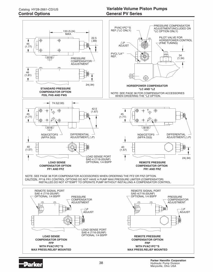
Control Options General PV Series
(1.34) 34
(1.77) 45
(1.67) 42.5
(1.77) 45
(.89)22.5
(1.77) 45
24(.94)
(1.57) 40
74.5(2.93)
24(.94)
(1.57) 40
(1.81) 46
MAX.133 (5.24)
CAUTION:
WHEN ORDERING THE *LZ OPTION.NOTE: SEE PAGE 38 FOR COMPENSATOR ACCESSORIES
REF.(*LC ONLY)PVAC1PC**S
REF.PVCL*LA**
ADJUST P
*LC OPTION ONLY)ADJUSTMENT(INCLUDED ONPRESSURE COMPENSATOR
(FINE TUNING)HORSEPOWER CONTROLPILOT VALVE FOR
*LC AND *LZHORSEPOWER COMPENSATOR
NOTE: SEE PAGE 38 FOR COMPENSATOR ACCESSORIES WHEN ORDERING THE FFZ OR FRZ OPTION.
INSTALLED.DO NOT ATTEMPT TO OPERATE PUMP WITHOUT INSTALLING A COMPENSATOR CONTROL. FF1& FR1 CONTROL OPTIONS DO NOT HAVE A PUMP MAX.PRESSURE LIMITER (COMPENSATOR)
OPTIONAL 1/4 BSPPSAE-4(7/16-20UNF)REMOTE SIGNAL PORT
ADJUSTMENTCOMPENSATORPRESSURE
ADJUST P
OPTIONAL 1/4 BSPPSAE-4 (7/16-20UNF)LOAD SENSE PORT
OPTIONAL 1/4 BSPPSAE-4 (7/16-20UNF)LOAD SENSE PORT
(NFPA D03)NG6/CETOP3
ADJUSTMENT( P)DIFFERENTIAL
T
P
T
P
MAX PRESS.RELIEF MOUNTEDWITH PVAC1PC**S
FRPCOMPENSATOR OPTION
REMOTE PRESSURE
OPTIONAL 1/4 BSPPSAE-4 (7/16-20UNF)REMOTE SIGNAL PORT
ADJUSTMENTCOMPENSATORPRESSURE
ADJUST P
MAX PRESS.RELIEF MOUNTEDWITH PVAC1PC**S
FFPCOMPENSATOR OPTION
LOAD SENSE
(NFPA D03)NG6/CETOP3
ADJUSTMENT( P)DIFFERENTIAL
FF1 AND FFZCOMPENSATOR OPTION
LOAD SENSE
ADJUSTMENTCOMPENSATORPRESSURE
FR1 AND FRZCOMPENSATOR OPTION
REMOTE PRESSURE
FDS, FHS AND FWSCOMPENSATOR OPTIONSTANDARD PRESSURE
Parker Hannifin CorporationHydraulic Pump DivisionMarysville, Ohio USA
Catalog HY28-2661-CD/US Variable Volume Piston Pumps
39
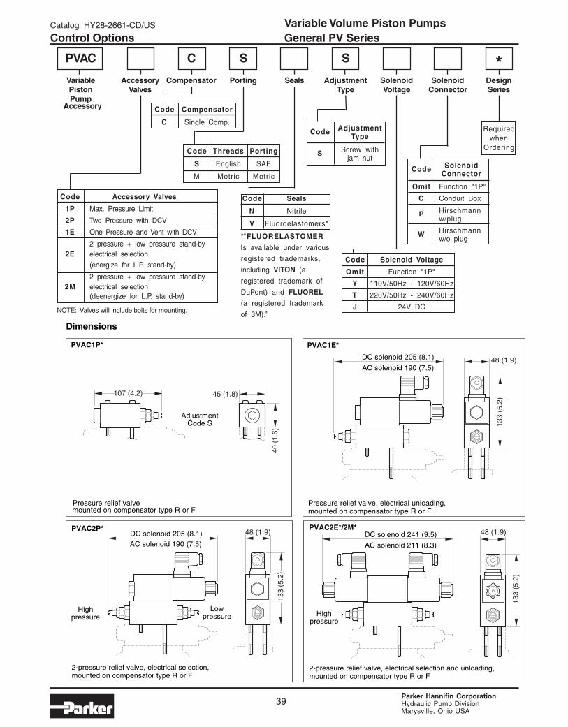
Code SolenoidConnector
Omit Function "1P"
C Conduit Box
P Hirschmannw/plug
W Hirschmannw/o plug
Code Accessory Valves
1P Max. Pressure Limit
2P Two Pressure with DCV
1E One Pressure and Vent with DCV
2 pressure + low pressure stand-by2E electrical selection
(energize for L.P. stand-by)
2 pressure + low pressure stand-by2M electrical selection
(deenergize for L.P. stand-by)
NOTE: Valves will include bolts for mounting.
PVAC C S S *Variable Accessory Compensator Porting Seals Adjustment Solenoid Solenoid DesignPiston Valves Type Voltage Connector SeriesPump
Code Threads Porting
S English SAE
M Metric Metric
Code AdjustmentType
S Screw withjam nut
Code Solenoid Voltage
Omit Function "1P"
Y 110V/50Hz - 120V/60Hz
T 220V/50Hz - 240V/60Hz
J 24V DC
Requiredwhen
Ordering
Accessory Code Compensator
C Single Comp.
Code Seals
N Nitrile
V Fluoroelastomers*
*“FLUORELASTOMER
Is available under various
registered trademarks,
including VITON (a
registered trademark of
DuPont) and FLUOREL
(a registered trademark
of 3M).”
PVAC1E*PVAC1P*
AdjustmentCode S
Pressure relief valve
PVAC2P* PVAC2E*/2M*
2-pressure relief valve, electrical selection,mounted on compensator type R or F
Highpressure
DC solenoid 205 (8.1)AC solenoid 190 (7.5)
Pressure relief valve, electrical unloading,mounted on compensator type R or F
Lowpressure
2-pressure relief valve, electrical selection and unloading,mounted on compensator type R or F
DC solenoid 205 (8.1)
AC solenoid 190 (7.5)
Dimensions
DC solenoid 241 (9.5)
AC solenoid 211 (8.3)
Highpressure
mounted on compensator type R or F
107 (4.2)
40 (
1.6)
45 (1.8)
48 (1.9)
133
(5.2
)
48 (1.9)
133
(5.2
)
48 (1.9)
133
(5.2
)
Control Options General PV Series
Parker Hannifin CorporationHydraulic Pump DivisionMarysville, Ohio USA
Variable Volume Piston PumpsCatalog HY28-2661-CD/US
40
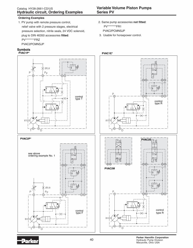
PVAC1E*
controltype R
PVAC2P*
see aboveordering example No. 1
controltype F
controltype T
controltype R
PVAC2E
PVAC2M
PVAC1P*Symbols
Hydraulic circuit, Ordering Examples Series PVOrdering Examples
1. PV pump with remote pressure control,
relief valve with 2 pressure stages, electrical
pressure selection, nitrile seals, 24 VDC solenoid,
plug to DIN 46350 accessories fitted:
PV********FRZ
PVAC2PCMNSJP
2. Same pump accessories not fitted:
PV********FR1
PVAC2PCMNSJP
3. Usable for horsepower control.

Parker Hannifin CorporationHydraulic Pump DivisionMarysville, Ohio USA
Catalog HY28-2661-CD/US Variable Volume Piston Pumps
41
PV Description Remark PVplusField 1 Pump type Field 1
PV Axial piston pump, open circuit, swashplate PVtype, variable displacement
PV Description Remark PVplusField 2 Nominal size, displacement Field 2
016 16 cm³/rev displacement 016020 20 cm³/rev displacement 020023 23 cm³/rev displacement 023028 28 cm³/rev displacement no longer available,
in future series PVM up to 250 bar032 32 cm³/rev displacement 032040 40 cm³/rev displacement 040046 46 cm³/rev displacement 046063 63 cm³/rev displacement 063080 80 cm³/rev displacement 080092 92 cm³/rev displacement 092130 130 cm³/rev displacement 140 cm³/rev displacement 140180 180 cm³/rev displacement 180250 250 cm³/rev displacement 270 cm³/rev displacement 270
PV 046 R 1 A 1 T 1 N PWS XX YY1 2 3 4 5 6 7 8 9 10 11 12
PV Description Remark PVplusField 3 Rotation Field 3
R clockwise (looking on shaft) RL counter-clockwise (looking on shaft) L
PV Description Remark PVplusField 4 Variation Field 4
1 standard 19 displacement adjusted 9
PV Description Remark PVplusField 5 Mounting interface, shaft Field 5
A SAE, 2/4-hole, keyed shaft 4 Bolt SAE Pilot, SAE Keyed Shaft DB SAE, 2/4-hole, splined shaft 4 Bolt SAE Pilot, SAE Spline Shaft EC SAE, 4-hole, splined shaft, second pump no longer availableD SAE, 4-hole, keyed shaft DE SAE, 4-hole, splined shaft EJ metric, splined shaft, second pump no longer availableK metric, keyed shaft KL metric, splined shaft L
PV Description Remark PVplusField 6 Was: displacement adjustment Now: ports, threads Field 6
1 with displacement adjustment metric, BSPP 1SAE, UNF 3SAE, ISO 6149 7metric, ISO 6149 8
PV 046 R 1 D 3 T 1 N FWS XX YY1 2 3 4 5 6 7 8 9 10 11 12
Cross reference ordering codes Parker series PV and Parker series PV plus
Code example PV:
code field no.:
Code example PV:
code field no.:
Direct Comparison Parker PV plus vs. Parker PV

Parker Hannifin CorporationHydraulic Pump DivisionMarysville, Ohio USA
Variable Volume Piston PumpsCatalog HY28-2661-CD/US
42
PV
Description Remark
PVplusField Thru drive and Second Pump Option Field
7T Thru shaft Capable with Cover
A 2/4 Bolt SAE "A" Pilot 3.25"/SAE "A" 9T Spline Coupler
2/4 Bolt SAE "B" Pilot 4.00"/SAE "B" 13T Spline Coupler
PV 046 R 1 A 1 T 1 N PWS XX YY1 2 3 4 5 6 7 8 9 10 11 12
PV 046 R 1 D 3 T 1 N FWS XX YY1 2 3 4 5 6 7 8 9 10 11 12
4 Bolt 80mm Pilot/W ? x ? x ? x 8f DIN 5480 Coupler
4 Bolt 100mm Pilot/W 25 x 1.5 x 15 x 8f DIN 5480 Coupler
4 Bolt 125mm Pilot/W 32 x 1.5 x 20 x 8f DIN 5480 Coupler
2/4 Bolt SAE "B" Pilot 4.00"/SAE "BB" 15T Spline Coupler
2 Bolt SAE "AA" Pilot 2.00"/SAE "A" 9T Spline
PV Description Remark PVplusField 9 Seal material Field 9
N NBR NV FPM V
PV Description Remark PVplusField 10 Compensator options Field 10
**S standard pressure compensator only fast response option available F*S*RC remote pressure compensator only fast response option available FRC*R1 remote pressure compensator with D03 interface only fast response option available FR1*F1 load-sensing compensator with D03 interface only fast response option available FF1*L* horse power compensator no longer for load sensing *L*
PV Description Remark PVplusField 11 Design series pump Field 11
not required on order
PV Description Remark PVplusField 12 Design series compensator Field 12
not required on order
814
C
H
8
2
KW
27
B 7
J 2
Y 7
7TA
814
C**
H
3
3
K****W
33
B 3
J 3
Y# 7
B* 7
C*** 7
W 7
2/4 Bolt SAE "C" Pilot 5.00"/SAE "C" 14T Spline Coupler
2 Bolt SAE "A" Pilot 3.25"/SAE "A" 9T Spline Coupler 4 Bolt SAE "B" Pilot 4.00"/SAE "B" 13T Spline Coupler
2 Bolt SAE "B" Pilot 4.00"/SAE "B" 13T Spline Coupler
4 Bolt SAE "C" Pilot 5.00"/SAE "C" 14T Spline Coupler
2 Bolt SAE "C" Pilot 5.00"/SAE "C" 14T Spline Coupler
2 Bolt SAE "B" Pilot 4.00"/SAE "BB" 15T Spline Coupler
4 Bolt SAE "B" Pilot 4.00"/SAE "BB" 15T Spline Coupler
*Not available with size 1**Size 2 or larger***Not available with size 1 and 2****Only available with 032 and larger#Only available with size 1
*Consult Factory for assistance in crossing over PV model codes that
are not shown.
Cross reference ordering codes Parker series PV and Parker series PV plus
Code example PV:
code field no.:
Code example PV:
code field no.:
Direct Comparison Parker PV plus vs. Parker PV
Parker Hannifin CorporationHydraulic Pump DivisionMarysville, Ohio USA
Catalog HY28-2661-CD/US Variable Volume Piston Pumps
43
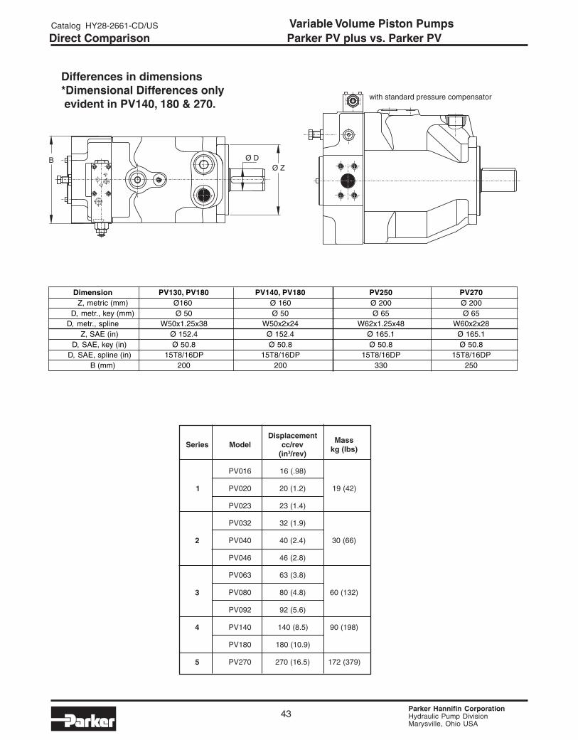
Direct Comparison Parker PV plus vs. Parker PV
Dimension PV130, PV180 PV140, PV180 PV250 PV270Z, metric (mm) Ø160 Ø 160 Ø 200 Ø 200
D, metr., key (mm) Ø 50 Ø 50 Ø 65 Ø 65D, metr., spline W50x1.25x38 W50x2x24 W62x1.25x48 W60x2x28
Z, SAE (in) Ø 152.4 Ø 152.4 Ø 165.1 Ø 165.1D, SAE, key (in) Ø 50.8 Ø 50.8 Ø 50.8 Ø 50.8
D, SAE, spline (in) 15T8/16DP 15T8/16DP 15T8/16DP 15T8/16DPB (mm) 200 200 330 250
Differences in dimensions*Dimensional Differences only evident in PV140, 180 & 270.
seireS ledoMtnemecalpsiD
ver/ccni( 3 )ver/
ssaM)sbl(gk
610VP )89.(61
1 020VP )2.1(02 )24(91
320VP )4.1(32
230VP )9.1(23
2 040VP )4.2(04 )66(03
640VP )8.2(64
360VP )8.3(36
3 080VP )8.4(08 )231(06
290VP )6.5(29
4 041VP )5.8(041 )891(09
081VP )9.01(081
5 072VP )5.61(072 )973(271
Parker Hannifin CorporationHydraulic Pump DivisionMarysville, Ohio USA
Variable Volume Piston PumpsCatalog HY28-2661-CD/US
44
Use of Relief ValveThe use of a relief valve, while not mandatory is
recommended in the main circuit to supresshydraulic shock loads and adds additional systemprotection.
Fluid RecommendationsPremium quality hydraulic oil with a viscosity range
between 150-250 SSU (30-50 cst.) at 100°F (38°C).
Normal operating viscosity range between 80-1000
SSU (17-180 cst.). Maximum start-up viscosity is
4000 SSU (1000cst.).
Note: Consult Parker when exceeding 160°F (71°C)
operation. Oil should have maximum anti-wear
properties, rust and oxidation treatment.
FiltrationFor maximum pump and system component life,the system should be protected from contaminationat a level not to exceed 125 particles greater than10 microns per milliliter of fluid. (SAE Class 4/ISO16/13.) Due to the nature of variable displacementpumps, variations in pump inlet conditions, fluidacceleration losses, system aeration, and dutycycle we do not recommend suction line filters. Wedo recommend the use of a properly sized, in-tank,suction strainer. Contact your Parker representativefor assistance.
Start-UpOn initial start-up, the pump case must be filledwith fluid. Pressure adjustments should be reducedand the circuit should be open to permit priming.
Special InstallationsConsult your Parker representative for anyapplication requiring the following:
Pressure above rated, drive speed above maximum,
indirect drive, fluid other than petroleum oil, fluid
temperature above 160°F (71°C)
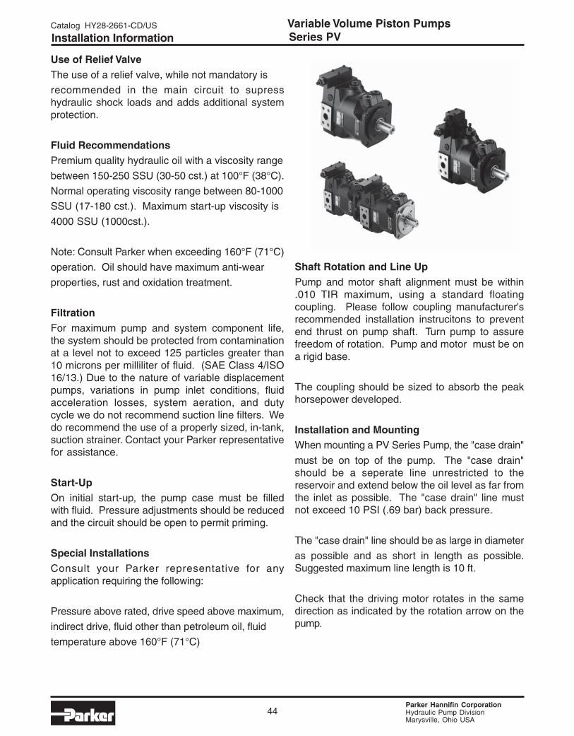
Shaft Rotation and Line UpPump and motor shaft alignment must be within.010 TIR maximum, using a standard floatingcoupling. Please follow coupling manufacturer'srecommended installation instrucitons to preventend thrust on pump shaft. Turn pump to assurefreedom of rotation. Pump and motor must be ona rigid base.
The coupling should be sized to absorb the peakhorsepower developed.
Installation and MountingWhen mounting a PV Series Pump, the "case drain"
must be on top of the pump. The "case drain"should be a seperate line unrestricted to thereservoir and extend below the oil level as far fromthe inlet as possible. The "case drain" line mustnot exceed 10 PSI (.69 bar) back pressure.
The "case drain" line should be as large in diameter
as possible and as short in length as possible.Suggested maximum line length is 10 ft.
Check that the driving motor rotates in the samedirection as indicated by the rotation arrow on thepump.
Installation Information Series PV
Parker Hannifin CorporationHydraulic Pump DivisionMarysville, Ohio USA
Catalog HY28-2661-CD/US Variable Volume Piston Pumps
45
Wear protection, wear reduction
Wear protection resp. wear reduction
In hydraulic components there are many glidingcontacts partly under high (side) loads. Besidethe correct viscosity, which on one hand isresponsible for the required supply of lubricatingfluid to the gap, on the other hand assures a stablelubricating film, the wear reduction capability ofthe hydraulic fluid is of major importance.
The describing parameter, the, Schadenskraftstufe"(load carrying capability), is determined in the FZG-normal test A/8, 3/90 according to DIN 51354 part2 (gear transmission test rig, 12 defined load stepsat 90o Cstar t temperature and 8,3 m/scircumferance speed).
Depending on the nominal working pressure thefollowing FZG Numbers is recommended!
nominal pressure bar (PSI) FZG
80 - 125 (1160 - 1812) > 5
125 - 200 (1812 - 2900) 5 - 6
200 - 250 (2900 - 3625) 7 - 9
250 - 320 (3625 - 4641) > 10
> 320 (4641) > 12
Max pressure limit: 1,25 x nominal pressure
Mineral oils are offered according to DIN 51 524
in different fluid types:
- HL-fluids according to DIN 51 524 part 2, normal
working load conditions, FZG 6-10.
- HLP-fluids according to DIN 51 524 part 3,
higher working load conditions, FZG > 10.
Modern HLP-fluids today usually come with a FZG
>12. They are equipped with wear prohibiting
additives, which ensure a high safety of operation
under severe working conditions.
Wear Protection, Wear Reduction Series PV

Parker Hannifin CorporationHydraulic Pump DivisionMarysville, Ohio USA
Variable Volume Piston PumpsCatalog HY28-2661-CD/US
46
Related Documents