Boeing Composite Airframe Damage Tolerance and Service Experience Allen J. Fawcett (ATF/DER) and Gary D. Oakes (ATF) Boeing Commercial Airplanes 787 Program

Welcome message from author
This document is posted to help you gain knowledge. Please leave a comment to let me know what you think about it! Share it to your friends and learn new things together.
Transcript

Boeing Composite Airframe Damage Tolerance and Service Experience
Allen J. Fawcett (ATF/DER) and Gary D. Oakes (ATF)Boeing Commercial Airplanes
787 Program

OutlineOutline
Boeing Design Criteria for Damage Tolerant CFRP Primary Structures and the relationship to MaintainabilityCFRP Structures Service Experience

Key Design Criteria for Primary CFRP Structure which effect MaintainabilityKey Design Criteria for Primary CFRP Structure which effect Maintainability
− Static strength as related to BVID (Barely Visible Impact Damage)
− Damage tolerance as related to VID (Visible Impact Damage)
− Environment and events as related to Lightning strike, Moisture, Temperature, Runway debris, Tool damage, Rapid decompression, Engine blade loss, Rotor burst, Hail, Bird impact, Tire and wheel threats
Stiffness and flutter
Durability• Fatigue• Corrosion
Fail safety
Producibility
Maintainability• Repairability• Inspectability
StructuresDesignCriteria
Design loads
Static strength
Damage Tolerance and safe life
Environment and discrete events
Crashworthiness

Sample Damage Tolerance Criteria-ImpactSample Damage Tolerance Criteria-Impact
1” to 4”diameter hemispherical impactor
Visible Damage with a high probability to be found during HMVNo damage growth for 2 times the planned inspection interval with LEFCapable of residual Limit strength
No energy cut-offVisible Impact Damage (VID) (Damage Tolerance FAR 25-571b)
1” diameter-hemispherical impactor
Barely visible damage which may not be found during HMVNo damage growth for 3 DSOs with LEFCapable of Ultimate strength
Consider higher than 1200 in-lbsConsider multiple, superimposed impactsConsider clustered impacts
Large Tool Drop (BVID)-repeat impact threat areas (FAR 25.305, AC20-107A)
1” diameter-hemispherical impactor
Barely visible damage which may not be found during HMVNo damage growth for 3 DSOs with LEFCapable of Ultimate strength
Up to 1200 in-lbs or a defined dent depth cut-off (considering relaxation) based on level of visibility as related to the inspection method.
Large Tool Drop (BVID)-general acreage(FAR 25.305, AC20-107A)
1” diameter-hemispherical impactor
No visible damageNo non-visible damage growth for 3 DSOsAccounted for in Ultimate Design Allowables
48 in-lbs normal to surface.Small Tool Drop
NotesRequirementCriteriaThreat

Barely Visible Impact Damage DefinedBarely Visible Impact Damage Defined
BVID
Small damages which may not be found during heavy maintenance general visual inspections using typical lighting conditions from a distance of five (5) feet
− Typical dent depth – 0.01 to 0.02 inches (OML)− Dent depth relaxation must be accounted for

Barely Visible Impact DamageBarely Visible Impact Damage
Small damages which may not to be found during heavy maintenance general visual inspections using typical lighting conditions from a distance of five (5) feet
Ultimate design strength requiredNo detrimental damage growth during Design Service Objective with LEFValidated by testing
BVID Impact Location

Criteria Requirements for Visible DamageCriteria Requirements for Visible Damage
Airframe must support design limit loads without failure.
No detrimental damage growth during fatigue cycling representative of the structure’s inspection interval.
− One missed inspection is assumed (two interval requirement)− Validated by testing
Airframe must be able to support residual strength loads until the damage is found and repaired.
− Damage state contains both visibly detectable and associated non-visibly detectable damage. Impact
Location

Wing Skin Visible Impact DamageWing Skin Visible Impact Damage
OML Impact, 1” Diameter impactor
Impact Energy: Greater than 8000 in-lbs
Residual Limit Load
No Growth for a missed inspection interval

Fuselage Skin Visible Impact DamageFuselage Skin Visible Impact Damage
Residual Limit Load
No Growth for a missed inspection interval
OML VID Impact
Inside damage associated with OML VID

Sample Damage Tolerance Criteria-ImpactSample Damage Tolerance Criteria-Impact
Ultimate design strength, no moisture intrusion and no detrimental damage growth during DSO for smaller size simulated hail ball. Limit residual strength for larger size simulated hail ball. Hail ball sizes and velocities based on statistical data.
Simulated hail ball up to a specified airspeed. In-flight Hail
Analysis, supported by component tests, shall demonstrate that the airframe will sustain required residual strength loadings without failure.
The airframe shall be capable of completing a flight during which complete failure of a structural segment, such as a frame or stiffener, with associated skin or web, occurs due to an undefined source.
“Failsafety”
Ultimate design strength, no moisture intrusion and no detrimental damage growth during DSO.
Up to 500 in-lb impact with simulated hail ball.Ground Hail ~ Non-Removable Structure
Ultimate design strength and no detrimental damage growth during DSO, including effect of environment
0.50-inch dia spherical object @ tangential tire speed. Runway Debris
RequirementCriteriaThreat

Sample Damage Tolerance Criteria-ImpactSample Damage Tolerance Criteria-Impact
Analyses, supported by large component testing, shall demonstrate ability to predict containment of dynamically imposed penetration damage to the pressurized fuselage.
The airplane should be able to complete a flight during which damage occurs due to uncontained:
- Fan blade impact or engine failure.- Failure of rotating machinery.
Accidental Damage ~ Breaching of
Pressurized Fuselage ~Threats from Rotating
Machinery
Compliance with these requirements is to be by analysis, supported by testing.
Structure, inside or outside of a pressurized fuselage compartment, whose failure could interfere with continued safe flight and landing, must withstand sudden release of pressure through an opening in any compartment resulting from:
- An opening, without regard to a specific cause, up to 20.0 sq. ft
- Opening due to probable airplane or equipment failures.
Accidental Damage ~ Breaching of
Pressurized Fuselage ~ Sudden Decompression
Residual strength demonstrated after cyclic load testing for two inspection intervals during which detection of the disbond or fracture is determined to likely occur
1) Demonstrate that damage to a bondline, due to manufacturing, environment, or accident, does not propagate to a residual strength condition of less than limit load, (or)2) Be designed with arrestment features such that limit load strength is maintained with a complete disbond between adjacent arrestment features.
Delamination or Disbonding of Bonded
Interfaces
Bird impact tests on test articles or components representative of A/C design.Where relevant data exists, compliance by analysis may be utilized.
Continued safe flight and landing following impact of a 4-lb bird (8lb for empennage) at Vc @ sea level, or 0.85 Vc @ 8000 feet.
Bird Impacts
RequirementCriteriaThreat

Sample Damage Tolerance Criteria-Lightning StrikeSample Damage Tolerance Criteria-Lightning Strike
Visually detectable damageImmediate structural repair not requiredIntermediate inspections may be requiredPermanent repair may be required after deferral period
Approximately 80th to 90th
percentile strike energy levelDispatch Lightning strike
Structural repair not requiredSealing/restoration of protection may be necessary at some point
Approximately 50th percentile strike energy level
NominalLightning strike
No penetration of fuel tankNo sparking or hot spotting in fuel tankProtection of systems from lightning attachmentContinued safe flight and landing loads per AC25-571-1c para 8.c.(1) and (2)
Strike level in accordance with zoning diagram
High Energy Strike
RequirementCriteriaThreat

Example –Lightning StrikeExample –Lightning Strike
CFRP structures must meet same lightning strike regulatory requirements as Aluminum structuresAdditionally 787 structures are designed, by requirement, to resist economic levels of lightning strike
787 composite panel; nominal strike causes superficial damage only. This damage would be expected to be within ADL and the airplane would be dispatched with deferred structural repair
Aluminum panel; nominal strike punctures through a similar gage aluminum panel. Immediate structural repair required to dispatch the airplane. Operational schedule impacted

Maintainability by Design
Utilization of in-service history to define and document appropriate ADLs validated by test.All structure is required to have a viable repair plan as part of the product definition data Viable repair plans will contain a suite of repairs including low/medium temp. wet lay-up and bolted repairsAll structure is required to be repairable using a minimalized list of standard techniques and materials
Environment and discrete events
Stiffness and flutter
Crashworthiness
Producibility
Maintainability• Repairability• Inspectability
StructuresDesignCriteria
Design loads
Static strength
Durability• Fatigue• Corrosion
Damage Toleranceand Safe Life
Fail Safety
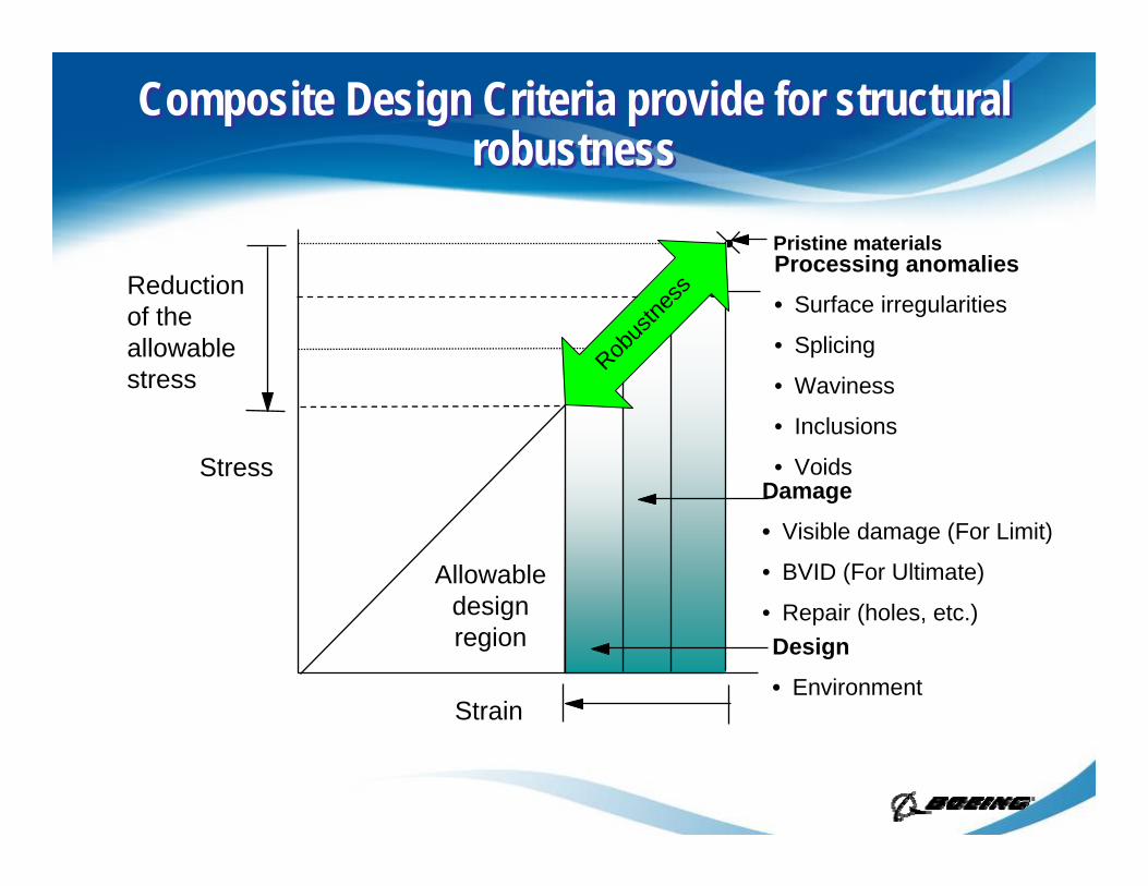
Composite Design Criteria provide for structural robustness
Composite Design Criteria provide for structural robustness
Processing anomalies
• Surface irregularities
• Splicing
• Waviness
• Inclusions
• VoidsDamage
• Visible damage (For Limit)
• BVID (For Ultimate)
• Repair (holes, etc.)Design
• Environment
Pristine materials
Allowable design region
Strain
Stress
Reduction of the allowable stress Rob
ustne
ss

Structural Design Criteria support MaintainabilityStructural Design Criteria support Maintainability
ADLs will be based on visible damage detection parameters- i.e. length, width and depth
Visual inspection techniques as for current aluminum airplanes
Instrumented Non Destructive Test (NDT) will not be required for damages within published ADLs
No new NDT techniques or equipment planned-inspections based on current 777 techniques and equipment modified to account for 787structural configurations
Instrumented NDT may be required for damages which exceed published ADLs
Methods validated by probability of detection studies and application on test articles.

Repairable by DesignRepairable by Design
Flush Bolted
123
Flush Bonded External Bolted

Repairs Validated by Structural TestRepairs Validated by Structural Test
MaterialSpecimens
Elements
Assemblies
Components
Airplanes
Increasing Levels of Complexity
Static TestFatigue TestGround & Flight Tests
Numerous test articles ranging from coupons to components have (or will have) repairs of the types planned for the SRM (including bolted, bonded, QCR, etc.) installed on them and will be tested.Tests include (but are not limited to): static and fatigue (with and without BVID, with and without environment), Tension, Compression and Combined Loads

OutlineOutline
Boeing Design Criteria for Damage Tolerant CFRP Boeing Design Criteria for Damage Tolerant CFRP Primary Structures and the relationship to Primary Structures and the relationship to MaintainabilityMaintainabilityCFRP Structures Service Experience

Service HistoryService History
Hundreds of CFRP and GFRP components havebeen in-service on Boeing aircraft since the late 50’s-including both honeycomb and solid laminate designs.
Majority of components have an acceptableservice record .
Large CFRP primary structures (737 NASA ACEE stabilizers-5 shipsets, 757/767 rudder/elevator, 777 empennage, flaps, rudder/elevator-500+ shipsets, ) have had an outstanding service history to date.

Boeing/NASA ACEE 737 Composite Horizontal Stabilizer Program
As part of the ACEE program, Boeing redesigned, manufactured, certified, & deployed five shipsets of 737-200 horizontal stabilizers using graphite-epoxy compositesBoeing 737 Composite Stabilizer Program Objectives:
Achieve a 20% weight reduction with respect to the existing metal structureManufacture at least 40% (by weight) of the components from composite materialsDemonstrate cost competitiveness of the structureObtain FAA certification for the structureEvaluate the structure in service

Horizontal Stabilizer Description
MATERIALNARMCO T300/5208
STRUCTURAL ARRANGEMENT Stiffened Skin Structural Box arrangement with I-section stiffener panels: the entire skin/ stiffener combination was co-cured toensure high bond reliability. Bolted Titanium spar lugs: this concept used two titanium plates bonded and bolted externally to apre-cured graphite-epoxy chord Honeycomb ribs were used because of the simplicity of the concept in terms of tooling, fabrication and cost
The structural arrangement was designed such that maximum commonality was achieved with the 737 metal configuration

737 Fleet Status
Five Shipsets were manufactured and certified in August 1982
Stabilizers removed from service 2002 (approx. 52000 hours, 48000 flights); teardown of L/H unit at Boeing; teardown of R/H unit at NIAR, Wichita State
B & D14 August 1984
5 / 1042
Stabilizers removed from service 2002 (approx. 39000 hours, 55000 flights); partial teardown of R/H unit at Boeing
B & C17 July 19844 / 1036
Damaged beyond repair 1990; partial teardown completed in 1991 (17300 hours, 19300 flights)
B11 May 19843 / 1025
In service (61372 hours, 46380 flights, as of May 31, 2006)
A21 March 1984
2 /1012In service (60024 hours, 44712 flights)A2 May 19841 / 1003
Status as of March 31, 2006 (except as noted)AirlineEntry into Service
Shipset / Production
Line #

737 Horizontal Stabilizer In-Service Experience737 Horizontal Stabilizer In-Service Experience
Four reported service-induced damage incidents2 De-icer impact damages on upper surface panels. Impacts were relatively minor. Damage limited to the skin, not affecting the stiffener elements.− Repair accomplished on site, in-situ using a low temperature, wet
layup repair.Fan blade penetration of lower skin. Penetration missed the stiffener elements. Damage was limited to a small area of the skin panel.− Repair accomplished on site, in-situ using a low temperature, wet
layup repair.Impact indications found on the lower leading edge panel forward of the front spar. Visible damage to the front spar web and upper and lower chord radii.− Bolted repair using titanium reinforcements
All units returned to service

777 In-Service Experience-CFRP Floor Beams777 In-Service Experience-CFRP Floor Beams
− No reported in-service repairs of composite floor beams*
− Fatigue cracking and corrosion in aluminum floor beams is fairly common and costly
* 500 aircraft in service

777 In-Service Experience-CFRP Empennage777 In-Service Experience-CFRP Empennage
5 reported service-induced damage incidents associated with the main torque boxes
FOD damage due to engine run-up− Area of skin/stringer disbond repaired with blind fasteners
Tip damage due to impact while taxiing− No damage to CFRP primary structural components
Hailstorm damage− No damage to main torque box structure
Damage due to impact with maintenance stand− Damage to front spar, main torque box skins, aux spar and leading edges− Bolted titanium sheet metal repair on front spar, skin, other parts replaced
Damage due to impact with service truck− Damage to front spar and main torque box skin− Bolted titanium sheet metal repair on front spar and skin

777 In-Service Experience-Details777 In-Service Experience-Details
Empennage Stringer Disbond - Engine Thrown Debris
AOG Damage Description
Straight-forward, effective repair

777 In-Service ExperienceSydney Hailstorm
777 In-Service ExperienceSydney Hailstorm

777 In-Service ExperienceSydney Hailstorm
777 In-Service ExperienceSydney Hailstorm
2.5” to 3.0” hail dented the fixed 5 ply honeycomb structure shown here but did no damage to the CFRP main torque box

777 In-Service Experience-Details777 In-Service Experience-Details
Skin/Spar Damage—Ground Handling Equipment Impact
Conventional Bolted Repair
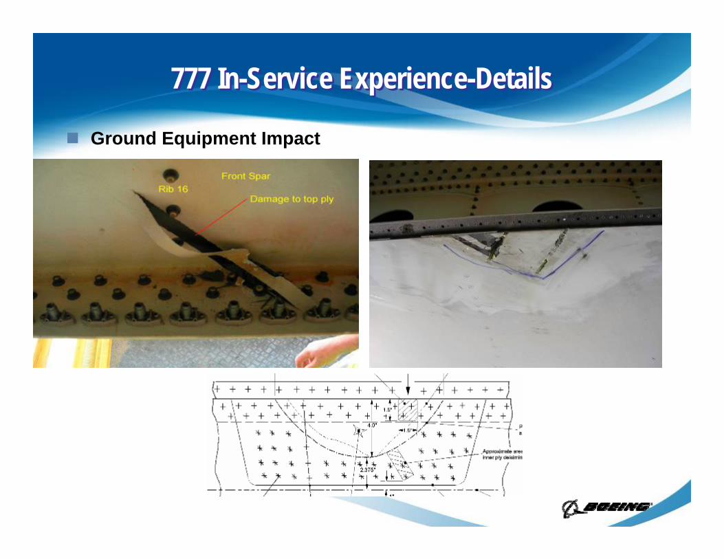
777 In-Service Experience-Details777 In-Service Experience-Details
Ground Equipment Impact

SummarySummary
In-service experience with primary composite structure has been excellentVisual based inspection program validated. In-service NDT techniques validatedDamage occurrences are at or below those for equivalent metal structureRepair techniques have proven to be effective and efficiently applied
Related Documents