BLUE POWER World quality leader in independent electric power

Welcome message from author
This document is posted to help you gain knowledge. Please leave a comment to let me know what you think about it! Share it to your friends and learn new things together.
Transcript

BLUE POWERWorld quality leader in independent electric power

ABOUt VictROn EnERgy
With over 30 years’ experience, Victron Energy enjoys an unrivalled reputation for technical innovation, reliability and quality, and is a world leader in the supply of self-supporting electric power. Our products have been designed to meet the most demanding situations faced by a diversity of craft, recreational and commercial alike, whilst we also cater for many other industrial and commercial applications. Our product range includes sine wave inverters and inverter/ chargers, battery chargers, DC/DC converters, transfer switches, Gel and AGM batteries, alternators, battery monitors, complete network solutions and many other innovative solutions.
[ Products range ]
• Sinewave Inverters • Combined Inverter/chargers • Automatic Battery Chargers • DC DC Converters • Transfer Switches • Deep Cycle Gel and AGM batteries • High Power Alternators • Battery Monitors • DC Distribution Units • Control and Distribution Panels• Battery Isolators • Shore Power Connection Kits• System Monitoring and Control• Solar Panels
[ Applications ]
• Solar and wind power systems• Yachts and commercial vessels • Special vehicles such as live broadcasting vehicles, ambulances, service vans, trains, caravans etc • Industrial • Telecom• Emergency power supply • Remote areas where there is no continuous supply

chARActERistics 230VAc/50hZ
PhOEnix inVERtER230VAC/50HZ
• sinusMax - superior engineering True sine wave inverter with optimised efficiency but without compromise in performance. Employing hybrid HF technology, the result is a top quality product with compact dimensions, light in weight and capable of supplying power, problem-free, to any load.
• Extra start-up power A unique feature of the SinusMax technology is very high start-up power. Phoenix inverters, however, are well suited to power up difficult loads such as refrigeration compressors, electric motors and similar appliances.
• Virtually unlimited power thanks to parallel and 3-phase operation capability Up to 10 units Phoenix 24/5000 can operate in parallel to achieve 50KVA power output. Operation in 3-phase configuration is also possible.
• to transfer the load to another Ac source: the automatic transfer switch If an automatic transfer switch is required on models rated at 1200 VA or more, we re- commend using the Phoenix Multiplus instead. The switch is included in these products and the charger function of the Multi can be disabled. For our lower power models we recommend the use of our Filax Automatic Transfer Switch. Computers and other electronic equipment will continue to operate without disruption because both the Filax and the Phoenix Multi feature a very short switchover times (less than 20 milliseconds).
• computer interface All models rated at 1200 VA or more have a RS-485 computer interface. Together with the VEConfigure software, all parameters of the inverters can be customised. The inverters can also be connected to VEnet, the power control network of Victron Energy.
[ 12V: 180-5000 VA ][ 24V: 180-5000 VA ][ 48V: 180-5000 VA ]
Computer controlledoperation and monitoring (Victron Interface Mk2)
Battery Alarm An excessively high or low battery voltage is indicated by an audible and visual alarm, and a relay for remote signalling.
1) Battery cables of 1.5 meter 2) Multipurpose relay which can be set for general alarm, DC under voltage or genset starts signal function 3) Suitable for parallel and 3-phase 4) Protectiona. Output short circuit b. Overload c. Battery voltage too high d. Battery voltage too low e. Battery reverse polarity detection f. 230 V AC on inverter output g. Input voltage ripple too high h. Temperature too high
AccEssORiEs Phoenix 12 Voltinverter 14 Volt 48 Volt
12/18024/180
12/35024/35048/350
12/75024/75048/750
C12/1200C24/1200
C12/1600C24/1600
C12/2000C24/2000
12/300024/300048/3000
24/500048/5000
Input voltage range (VCD) 10.5 - 15.521.0 - 31.042.0 - 62.0
10.5 - 15.521.0 - 31.042.0 - 62.0
10.5 - 15.521.0 - 31.042.0 - 62.0
9.5 - 1619.5 - 32.2
9.5 - 1619.5 - 33
9.5 - 1619.5 - 33
9.5 - 1619.5 - 3338 - 66
9.5 - 1619.5 - 3338 - 66
Cont. output power at 25 ˚C (VA) 180 350 750 1200 (3) 1600 (3) 2000 (3) 3000 (3) 5000 (3)
Cont. power at 25 ˚C / 40 ˚C (W) 175 / 150 300 / 250 700 / 650 1000 / 900 (4) 1300 / 1200 (4) 1600 / 1450 (4) 2500 / 2000 (4) 4500 / 4000 (4)
Peak power (W) (W)
200 500 1400 2400 23003000
4000 6000 10000
Max. Efficiency 12/24/48 V (%) 91 / 92 / 92 90 / 91 / 92 91 / 93 / 94 93 / 94 93 / 94 93 / 94 93 / 94 / 95 94 / 95
Zero-load power 12/24/48V (w) 2.2 / 3.0 / 4.0 3.0 / 3.5 / 4.0 12 / 12 / 12 8 / 11 8 / 11 10 / 10 15 / 15 / 16 25
Zero-load power in AES mode n.a. n.a. 3/4/5 5/8 5/8 8/10 10/10/12 20/20
Muti purpose relay driver or relay (2)
relay relay relay relay x2 relay x2
Protection (4) a,b,d,h a,b,d,h a,b,d,h a,b,d,c,d,f,g,h a,b,d,c,d,f,g,h a,b,d,c,d,f,g,h a-h a-h
Common Characteristics Output: 230 V ± 2% /50/60 Hz ± 0,2% (switch selectable) Operating temperature range: -20 to +50˚C Humidity: max 95%
ENCLOSURE
Material & Colour Aluminium (blue RAL 5012)
Battery-connection 1) 1) Screw conn. 1) 1) M8 bolts M8 bolts 4 M8 bolts
230 V AC-connection IEC-320 (IEC-320 plug included) or Schuko G-ST18i G-ST18i Spring-clamp Screw-clamp
Protection category IP20 IP20 IP20 IP21 IP21 IP21 IP21 IP21
Weight (kg) 2.7 3.5 2.7 10 10 12 18 30
Dimensions (hxwxd in mm) 72x132x200 72x155x237 72x180x295 375x214x110 375x214x110 520x255x125 362x258x218 444x328x240
ACCESSORIES
Remote panel (RS485) √ (PIV) √ (PIV) √ (PIV) √ (PIV) √ (PIV)
Remote on-off switch √ √ √ √ √ √ √ √
Automatic transfer switch FILAX FILAX FILAX Phoenix Multi Quattro
STANDARDS
Safety EN 60950 EN 60335-1
Emission / Immunity EN 55014-1 / EN55014-2
Automotive Directive 95/54/EC and 2004/104/EC
BMV-600-S Battery Monitor
Phoenix Inverter Control (PIV)

chARActERistics 120VAc/60hZ
• sinusMax - superior engineering True sine wave inverter with optimised efficiency but without compromise in performance. Employing hybrid HF technology, the result is a top quality product with compact dimensions, light in weight and capable of supplying power, problem-free, to any load.
• Extra start-up power A unique feature of the SinusMax technology is very high start-up power. Phoenix inverters, however, are well suited to power up difficult loads such as refrigeration compressors, electric motors and similar appliances.
• Virtually unlimited power thanks to parallel and 3-phase operation capability Up to 6 units Phoenix 24/3000 can operate in parallel to achieve 18KVA power output. Operation in 3-phase configuration is also possible.
• to transfer the load to another Ac source: the automatic transfer switch If an automatic transfer switch is required on models rated at 1200 VA or more, we re- commend using the Phoenix Multiplus instead. The switch is included in these products and the charger function of the Multi can be disabled. For our lower power models we recommend the use of our Filax Automatic Transfer Switch. Computers and other electronic equipment will continue to operate without disruption because both the Filax and the Phoenix Multi feature a very short switchover times (less than 20 milliseconds).
[ 12V: 180-5000 VA ][ 24V: 180-5000 VA ]
AccEssORiEs
PhOEnix inVERtER120VAC/60HZ
Phoenix 12 Voltinverter 24 Volt
12/18024/180
12/35024/350
12/75024/750
Input voltage range (VCD) 10.5 - 15.5 / 21.0 - 31.0
Cont. output power at 25 ˚C (VA) 180 350 750
Cont. power at 25 ˚C / 40 ˚C (W) 175 / 150 300 / 250 700 / 650
Peak power (W) (W) 350 700 1400
Max. Efficiency 12/24/48 V (%) 87 / 88 89 /89 91 / 93
Zero-load power 12/24/48V (w) 2.6 / 3.8 3.1 / 5.0 14 / 14
Zero-load power in AES mode n.a. 3 / 4 / 5
Protection (5) a - g
Common Characteristics Output: Output: 120 V ± 2% / 60 Hz ± 0,2% (switch selectable) Operating temperature range: 0 - 122 ˚F Humidity: max 95%
ENCLOSURE
Material & Colour Aluminium (blue RAL 5012)
Battery-connection 1) 1) Screw conn.
230 V AC-connection NEMA5-15R
Protection category IP20 IP20 IP20
Weight (kg) 2.7 / 5.4 3.5 / 7.7 2.7 / 5.4
Dimensions (hxwxd in mm) 72x132x200 72x155x237 72x180x295
ACCESSORIES
Remote panel (RS485)
Remote on-off switch √ √ √
Automatic transfer switch FILAX FILAX FILAX
STANDARDS
Safety EN 60950 EN 60950 EN 60950
Emission / Imunnity EN 55014-1 / EN55014-2
Automotive Directive 95/54/EC and 2004/104/EC
1) Battery cables of 1.5 meter 2) Relay driver: open Collector 66V 3) Multipurpose relay which can be set for general alarm, DC under voltage or genset starts signal function 4) Suitable for parallel and 3-phase 5) Protectiona. Output short circuit b. Overload c. Battery voltage too high d. Battery voltage too low e. Battery reverse polarity detection f. 230 V AC on inverter output g. Input voltage ripple too high h. Temperature too high
BMV-600 S Battery Monitor
Phoenix InverterControl (PIV)
Computer controlledoperation andmonitoring (VictronInterface Mk2)
Battery AlarmAn excessively high or low battery voltage isindicated by an audibleand visual alarm, and a relay for remote signalling.

MULtiPLUs230VAC/50HZ
chARActERistics 230VAc/50hZ
• Multi-functional, with intelligent mains and generator power management The multi gets its name from the multiple functions it can perform. It is a powerful true sine wave inverter, a sophisticated battery charger that features adaptive charge technology, and a high-speed AC transfer switch in a single compact enclosure.
• Uninterrupted Ac power (UPs function) In the event of a grid failure, or mains or generator power being disconnected, the inverter within the Multi is automatically activated and takes over the supply to the connected loads. This happens so fast (less than 20 milliseconds) that computers and other electronic equipment will continue to operate without disruption.
• Powercontrol - Dealing with limited generator, shore side or grid power With the Phoenix Multi Control Panel a maximum generator or shore current can be set. The Multi will then take account of other AC loads and use whatever is extra for charging, this preventing the generator or mains supply from being overloaded.
• PowerAssist - Boosting the capacity of grid or generator power, an innovative feature of the MultiPlus This feature takes the principle of PowerControl to a further dimension allowing the MultiPlus to supplement the capacity of the alternative source. Where peak power is so often required only for a limited period, the Phoenix MultiPlus will make sure that insufficient shore or generator power is immediately compensated for by power from the battery.
• Four stage adaptive charger and dual bank battery charging The main output provides a powerful charge to the battery system by means of advanced ‘adaptive charge’ software that fine-tunes the three stage automatic process to suit the condition of the battery, and adds a fourth stage for long periods of float charging. In addition to this, the Multi will charge a second battery using an independent trickle charge output intended for a main engine or generator starter battery.
[ 12V: 800-3000 VA ][ 24V: 800-8000 VA ][ 48V: 3000 - 10000 VA ]
AccEssORiEs
VEBus digitial panelThis is a remote controland monitoring panelfor the Phoenix Multiplus
Blue Power panelVE.Net / VE.Bus panel
Computer controlledoperation andmonitoring (VictronInterface Mk2)
Victron Global Remote
Multiplus 12V / 24V / 48V C12/800/16C24/800/35
C12/1200/50C24/1200/25
C12/1600/70C24/1600/40
C12/2000/80C24/2000/50
12/3000/12024/3000/7048/3000/35
24/5000/12048/5000/70
24/800048/8000 48/10000
PowerControl / PowerAssist Yes / Yes
Transfer switch (A) 16 30 16 or 50 50 100 100
INVERTER
Input voltage range (VCD) 9,5 – 17 V 19 – 33 V 38 – 66 V
Output 230 V ± 2% /50 Hz ± 0,1% Frequency: 50 Hz ± 0.1 %
Cont. output power at 25 ˚C (VA) (5) 800 1200 1600 2000 3000 5000 8000 10000
Cont. output power at 25/40 ˚C (W) 700 / 650 1000 / 950 1300 / 1200 1600 / 1450 2500 / 2000 4250 / 3350 7000 / 6300 9000 / 8000
Peak power (W) 1600 2400 3000 4000 6000 10.000 16000 20000
Maximum efficiency (%) 92 / 94 93 / 94 93 / 94 / 95 94 / 95 95 / 96 96
Zero-load power (W) 8 / 10 9 / 11 15 / 15 / 16 25 / 25 30 / 35 35
Zero-load power in AES Modus 5 / 8 7 / 9 10 / 10 / 12 20 / 20 25 / 30 30
Zero-load power in Search Modus 2 / 3 3 / 4 4 / 5 / 5 5 / 6 8 / 10 10
CHARGER
AC input 187-265 VAC, 45-55 HZ, Power factor:1
Charge voltage ‘absorption’ (V DC) 14,4 / 28,8 / 57,6
Charge voltage ‘float’ (V DC) 13,8 / 27,6 / 55,2
Storage mode (V DC) 13,2 / 26,4 / 52,8
Charge current starter battery (A) 4 (Only by the 12V and 24V)
Battery temperature sensor Yes
GENERAL
Auxiliary output (A) (5) n.a. Yes (10A) Yes (25A) 50 50
Multi purpose relay driver or relay relay driver (7) relay 3x relay
Protection (5) a - g
VE.Bus communication port For parallel and three phase operation, remote monitoring and system integration
General purpose com. port (7) 1x 1x 3x 3x
Common Characteristics Operating temp. range: -20 - 50 ˚C (fan assisted cooling) Humidity (non condesing) : max 95%
ENCLOSURE
Common Characteristics Material & Colour: aluminum (blau RAL 5012) Protection category: IP 21
Battery-connection Battery cabels 1,5 m M8 Studs
230 V AC-connection G-ST18i Stecker Spring-clamp Screw-clamp
Weight (kg) 10 12 18 30 41 45
Dimensions (hxwxd in mm) 375x214x110 520x255x125 362x258x218 444x328x240 470x350x280 470x350x280
STANDARDS
Safety EN 60335-1, EN60335-2-29
Emission / Immunity EN55014-1, EN 61000-3-2 / EN 55014-2, EN 61000-3-3
Automotive Directive 95/54/EC and 2004/104/EC
1) Can be adjusted to 60 HZ; 120 V 60 Hz on, request 2) Protection key: a) output short circuit b) overload c) battery voltage too high
d) battery voltage too low e) temperature too high f) 230 VAC on inverter output g) input voltage ripple too high 3) Non linear load, crest factor 3:1 4) At 25 °C ambient
5) Switches off when no external AC source available, Available on 3kVA models with 50A transfer switch only 6) Programmable relay that can a. o. be set for general alarm,
DC undervoltage or genset start /stop function, AC rating: 230V/4A DC rating: 4A up to 35VDC, 1A up to 60VDC 7) Open collector output 66V 40mA

chARActERistics 230VAc/50hZ
• two Ac inputs with integrated transfer switch
• two Ac outputs The main output has no-break functionality. The second output is live only when AC is available on one of the inputs of the Quattro.
• Virtually unlimited power thanks to parallel operation Up to 6 Quattro’s can operate in parallel.
• three phase capability Three units can be configured for three-phase output.
• Powercontrol - Dealing with limited generator, shore-side or grid power
• PowerAssist - Boosting shore or generator power
• solar energy: Ac power available even during a grid failure The Quattro can be used in off grid as well as grid connected PV and other alternative energy systems.
• A grid connected PV system will shut down when the grid fails! not anymore with a Quattro and batteries
[ 12V: 3000 VA ][ 24V: 3000 VA ]
[ 12V: 5000 VA ][ 24V: 5000 VA ][ 48V: 5000 VA ]
QUAttRO230VAC/50HZ
Quattro 12/3000/12024/3000/70
12/5000/20024/5000/120 48/5000/70
24/800048/8000
48/10000
PowerControl / PowerAssist Yes / Yes
Integrated Transfer switch Input voltage range: 187-265 VAC Input frequency: 45-55 Hz Power factor: 1
Maximum feed through current (A) 50/30 30/30 / 50/30 2x100 2x100
INVERTER
Input voltage range (V DC) 9.5-17 / 19-33 9.5-17 / 19-33 / 38 66 19-33 / 38-66 38-66
Output (1) Output voltage: 230 VAC ± 2%
Cont. output power at 25 ˚C (VA) (2) 3000 5000 8000 10000
Cont. output power at 25 ˚C (W) 2500 4250 7000 9000
Cont. output power at 40 ˚C (W) 2000 3350 6300 8000
Peak power (W) 6000 7500 / 7800 16000 20000
Maximum efficiency (%) 92 / 94 94 / 95 95 / 96 96
Zero-load power (W) 15 30 30 / 35 35
Load shedding output 0 / 25 10 / Switches off when no external AC source available
CHARGER
Charge voltage ‘absorption’ (V DC) 14.4 / 28.8 14.4 / 28.8 / 57.6 28.8 / 57.6 57.6
Charge voltage ‘float’ (V DC) 13.8 / 27.6 13.8 / 27.6 / 55.2 27.6 / 55.2 55.2
Storage mode (V DC) 13.2 / 26.4 13.2 / 26.4 / 52.8 26.4 / 52.8 52.8
Charge current house battery (A) 120 / 70 200 / 120 / 70 200 / 110 140
Charge current starter battery (A) 4 (12V and 24V models only)
Battery temperature sensor Yes
GENERAL
Multi purpose relay (1) 1x 3x / 1x / 1x 3x 3x
General purpose com. port (7) 1x 2x / 1x / 1x 2x 2x
Common Characteristics (3) Operating temp.: -20 to +50 ˚C (fan assisted cooling) Humidity (non condensing) : max 95% / a-f
ENCLOSURE
Common Characteristics Material & Colour: aluminium (blue RAL 5012) Protection category: IP 21
Battery-connection Four M8 bolts (2 plus and 2 minus connections)
230 V AC-connection Screw clamp 13 mm² (AWG 6)
Weight (kg) 19 30 41 45
Dimensions (hxwxd in mm) 362x258x218 444x328x240 470 x 350 x 280
STANDARDS
Safety EN 60335-1, EN 60335-2-29
Emissions / immunity EN 55014-1, EN 61000-3-2 / EN 55014-2, EN61000-3-3
Automotive Directive 2004/104/EC
1) Multipurpose relay which can be set for general alarm, DC under voltage or genset starts signal function 2) Suitable for parallel and 3-phase 3) Protection a. Output short circuit b. Overload c. Battery voltage too high d. Battery voltage too low e. Battery reverse polarity detection f. 230 V AC on inverter output g. Input voltage ripple too high h. Temperature too high
[ 24V: 8000 VA ][ 48V: 8000 VA ]
[ 48V: 10000 VA ]

chARActERistics 120VAc/60hZ
• Multi-functional, with intelligent shore and generator power management The multi gets its name from the multiple functions it can perform. It is a powerful true sine wave inverter, a sophisticated battery charger that features adaptive charge technology, and a high-speed AC transfer switch in a single compact enclosure.
• Uninterrupted Ac power (UPs function) In the event of a grid failure, or mains or generator power being disconnected, the inverter within the Multi is automatically activated and takes over the supply to the connected loads. This happens so fast (less than 20 milliseconds) that computers and other electronic equipment will continue to operate without disruption.
• Virtually unlimited power thanks to parallel operation and three phase capability Up to 6 Multi’s can operate in parallel to achieve higher power output. Three units of the same model can be configured for three-phase output.
• Powercontrol - Dealing with limited generator or grid power With the Phoenix Multi Control Panel a maximum generator or shore current can be set. The Multi will then take account of other AC loads and use whatever is extra for charging, this preventing the generator or shore supply from being overloaded.
• PowerAssist - Boosting the capacity of shore or generator power, an innovative feature of the MultiPlus This feature takes the principle of PowerControl to a further dimension allowing the MultiPlus to supplement the capacity of the alternative source. Where peak power is so often required only for a limited period, the Phoenix MultiPlus/Quattro will make sure that insufficient shore or generator power is immediately compensated for by power from the battery.
• Four stage adaptive charger and dual bank battery charging The main output provides a powerful charge to the battery system by means of advanced ‘adaptive charge’ software that fine-tunes the three stage automatic process to suit the condition of the battery, and adds a fourth stage for long periods of float charging. In addition to this, the Multi will charge a second battery using an independent trickle charge output intended for a main engine or generator starter battery.
[ 12V: 2000-5000 VA ][ 24V: 2000-5000 VA ]
Input 1
Input 2
L1 ( no break)
L 2
N
GND
L2-1
L1-1
N 1
GND
L2-2
L1-2
N 2
GND
Output
120Vac
120Vac
120Vac
120Vac
120Vac
120Vac
Input 1
Input 2
L1 ( no break)
N
GND
L1-1
N 1
GND
L1-2
N 2
GND
Output
230Vac
230Vac
230Vac
PhOEnix MULtiPLUs/QUAttRO120VAC/60HZ
Multiplus12V / 24V
C 12/2000/80-30 120V 12/3000/120-50 120V 24/3000/70-50 120V
Quattro 24/5000/120 - 2x60120/240V
PowerControl Yes
PowerAssist Yes
Transfer switch (A) 30 A 50 A 60 A
INVERTER
Input voltage range (V DC) 9.5-17V 19-33V
Output Output voltage: 120 VAC ± 2% Frequency: 60 Hz ± 0,1%
Cont. output power at 25 ˚C (VA) (2) 2000 3000 5000
Cont. output power at 25/40 ˚C (W) 1600/1450 2500/2000 4250/3350
Peak power (w) 4100 6000 7500
Maximum efficiency (%) 93/94 93/94 94
Zero-load power (W) 10/10 15/15 30
CHARGER
AC input 120V or 120/240V Input voltage range: 95-140 VAC Input frequency: 45 65 Hz Power factor:1
Charge voltage ‘absorption’ (V DC) 14.4/28.8
Charge voltage ‘float’ (V DC) 13.8/27.6
Storage mode (V DC) 13.2/26.4
Charge current house battery (A) 80/50 120/70 120
Charge current starter battery (A) 4
Battery temperature sensor Yes
GENERAL
Multi purpose relay driver or relay (1) Relay
Protection (3) a-h
Common characteristics Operating temp. range: 0-120 ˚F (fan assisted cooling) Humidity (non condensing): max 95%
ENCLOSURE
Common Characteristics Material & Colour: aluminum (blue RAL 5012) Protection category: IP 21
Battery-connection M8 Studs Four M8 Blots (2+, 2-)
230 V AC-connection Spring-clamp Screw-clamp
Protection category IP 21
Weight (kg) 13 18 30
Dimensions (hxwxd in mm) 520x255x120 362x258x218 444x328x240
STANDARDS
Safety EN 60335-1, EN 60335-2-29
Emission / Immunity EN 55014-1, EN 55014-2/EN61000-3-2, EN 61000-3-3
Automotive Directive 95/54/EC abd 2004/104/EC
1) Multipurpose relay which can be set for general alarm, DC under voltage or genset starts signal function 2) Suitable for parallel and 3-phase 3) Protection a. Output short circuit b. Overload c. Battery voltage too high d. Battery voltage too low e. Battery reverse polarity detection f. 230 V AC on inverter output g. Input voltage ripple too high h. Temperature too high
120VAC split-phase version
230 VAC single-phase version

chARActERistics
• Universal input: 90-265 VAc or 90-350 VDc The charger will operate on whatever supply is available.
• Adaptive 4-stage charge characteristics: bulk - absorption - float - storage The Blue Power charger features a microprocessor controlled ‘adaptive’ battery management. The ‘adaptive’ feature will automatically optimise the charging process relative to the way the battery is being used.
• Less maintenance and aging when the battery is not in use: the storage Mode The storage mode kicks in whenever the battery has not been subjected to discharge during 24 hours. In the storage mode float voltage is reduced to 2,2 V/cell (13,2 V for a 12 V battery) to minimise gassing and corrosion of the positive plates. Once a week the voltage is raised back to the absorption level to ‘equalize’ the battery. This feature prevents stratification of the electrolyte and sulphation, a major cause of early battery failure.
• Protected against overheating and silent fan cooling Output current will reduce as temperature increases up to 60˚C but the Blue Power charger will not fail. The load and temperature controlled fan is practically inaudible.
• two LED’s for status indication Yellow LED: bulk charge (blinking fast), absorption (blinking slow). float (solid) Green LED: power on
[ 12V: 7-15 A ][ 24V: 5-8 A ]
BLUE POWER BAttERy chARgER iP20
Blue power charger IP 20 12/712/1012/15
24/524/8
Input voltage range 90-265 VAC, 90-350 VDC
Frequency 45-65 or DC
Charge voltage ‘absorption’ (V DC) 14.4 28.8
Charge voltage ‘float’ (V DC) 14 28
Charge voltage ‘storage’ (V DC) 13.2 26.4
Charge current (A) 7/10/15 5/8
Charge characteristic 4-stage adaptive
Minimum battery capacity (Ah) 24/36/55 16/24
Can be used as power supply Yes
Protection Battery reverse polarity (fuse in battery cable)Output short circuit, over temperature
Operating range -20 tot 60 °C Humidity: Max 95%
ENCLOSURE
Material & Colour Aluminium (blue RAL 5012)
Battery-connection Black and red cable of 1,5 meter
230 V AC-connection Cable of 1,5 meter with Europe class 1 plug (CE certified)
Protection category IP20
Weight (kg) 1.3
Dimensions (hxwxd in mm) 50x85x200
STANDARDS
Safety EN60335-1, EN60335-2-29
Emission EN55014-1, EN61000-3-2
Immunity EN55014-2, EN61000-3-3

chARActERistics[ 12V: 7-17 A ][ 24V: 3-12 A ]
BLUE POWER BAttERy chARgER iP65
• completely encapsulated: waterproof, shockproof and ignition protected Water, oil or dirt will not damage the Blue Power charger. The casing is made of cast aluminium and the electronics are molded in resin.
• Protected against overheating Can be used in a hot environment such as a machine room. Output current will reduce as temperature increases up to 60°C, but the Blue Power charger will not fail.
• Automatic three stage charging Once the absorption voltage has been reached to a low break point current (see specifications), or after a 20 hour absorption period. The battery is therefore effectively protected against overcharging and can remain permanently connected to the charger. The charger will automatically reset and start a new charge cycle after interruption of the AC supply.
• two LED’s for status indication Yellow LED: battery being charged Green LED: float charge, the battery is charged
9
Blue Power charger 12/7 12/17 24/3 24/12
Input voltage range (V AC) (1) 200-265
Frequency (Hz) 45-65
Charge voltage ‘absorption’ (V DC) 14.4 28.8
Charge voltage ‘float’ (V DC) 13.7 27.2
Charge current (A) 7 17 3 12
Charge characteristic 3 stage with max. 20 hours absorption time
Minimum battery capacity (Ah) 15 35 6 24
Breakpoint current (A) 0.7 1.7 0.3 1.2
Can be used as power supply Yes
Protection Battery reverse polarity (fuse in battery cable) Output short circuit, over temperature
Operating range -20 to 60 °C, Humidity Max: 100%
ENCLOSURE
Material & Colour Aluminium (blue RAL 5012)
Battery-connection Black and red cable of 1,5 meter
230 V AC-connection Cable of 1,5 meter with Europe class 1 plug (CE-certified)
Protection category IP 65
Weight (kg) 1.1 1.4 1.1 1.4
Dimensions (hxwxd in mm) 43x80x155 47x99x193 43x80x155 47x99x193
STANDARDS
Safety EN60335-1, EN 60335-2-29
Emission EN55014-1, EN61000-3-2
Immunity EN55014-2, EN61000-3-3
1) 120V / 60 Hz available

chARActERistics
• Adaptive 4-stage charge characteristic: bulk - absorption - float - storage The Phoenix charger features a microprocessor controlled ‘adaptive’ battery management system that can be preset to suit different types of batteries. The ‘adaptive’ feature will automatically optimise the process relative to the way the battery is being used.
• the right-amount of charge: adaptive charge When only shallow discharges occur (a yacht connected to shore power for example) the absorption time is kept short in order to prevent overcharging of the battery. After a deep discharge the absorption time is automatically increased to make sure that the battery is completely recharged.
• Preventing damage due to excessive gassing: the Batterysafe mode (see fig1. below) If, in order to quickly charge a battery, a high charge current in combination with a high absorption voltage has been chosen, the Phoenix charger will prevent damage due to excessive gassing by automatically limiting the rate of voltage increase once the gassing voltage has been reached (see the charge curve between 14,4 V and 15,0 V in fig.1 below).
• Less maintenance and aging when the battery is not in use: the storage mode (see fig.1 below) The storage mode kicks in whenever the battery has not been subjected to discharge during 24 hours. In the storage mode float voltage is reduced to 2,2 V/cell (13,2 V for 12 V battery) to minimise gassing and corrosion of the positive plates. Once a week the voltage is raised back to the absorption level to ‘equalize’ the battery. This feature prevents stratification of the electrolyte and sulphation, a major cause of early battery failure.
• to increase battery life: temperature compensation Every Phoenix charger comes with a battery temperature sensor. When connected, charge voltage will automatically decrease with increasing battery temperature.
• Battery voltage sense In order to compensate for voltage loss due to cable resistance, Phoenix chargers are provided with a voltage sense facility so that the battery always receives the correct charge voltage.
• computer interface Every Phoenix Charger is ready to communicate with a computer through its RS-485 data port. Together with our VEConfigure software, all parameters of the chargers can be customised. The chargers can also be connected to VENet, or to other computerised monitoring control systems.
[ 12V: 30-50 A ][ 24V: 16-25 A ]
PhOEnix BAttERy chARgER
Battery Monitor
Fig. 1
Computer controlled operation and monitoring(Victron interface Mk2b)
Phoenix Charger Control
Battery AlarmAn excessively high or lowbattery voltage is indicatedby an audible and visual alarm.
AccEssORiEs
Phoenix charger 12V/24V
12/3024/16
12/5024/25
Input voltage range 90-265 VAC, 90-400 VDC
Frequency (Hz) 45-65, PF:1
Charge voltage ‘absorption’ (V DC) 14.4 / 28.8
Charge voltage ‘float’ (V DC) 13.8 / 27.6
Storage mode (V DC) 13.2 / 26.4
Battery bank 3
Charge current house batt. (A)(2) 30/16 50/25
Charge current starter batt. (A) 4
Charge characteristics 4 stage adaptive
Battery capacity (Ah) 100-400100-200
200-800100-400
Temperature sensor Yes
Can be used as power supply Yes
Forced cooling Yes
Protection (1) a,b,c,d
Common characteristics Temperature: -20 to 60 °C (0 - 140°F) Max humidity: 95%
ENCLOSURE
Material & Colour Aluminium (blue RAL 5012)
Battery-connection M6 Studs
230 V AC-connection Screw-clamp 4mm²
Protection category IP21
Weight (kg) 3.8
Dimensions (hxwxd in mm) 350x200x108
STANDARDS
Safety EN60335-2-29
Emission EN55014, EN61000-3-2, EN61000-3-3
Immunity EN55014-2
Vibration IEC68-2-6: 10-150Hz/1.0G
Automotive directive 95/54/EC
1) Protection a. Output short circuit b. Battery reverse polarity detection c. Battery voltage too high d. Temperature too high 2) Up to 40 °C ambient

chARActERistics[ 24V: 30-50-80-100 A ][ 48V: 25-50 A ]
skyLLA tg BAttERy chARgER
• Perfect chargers for any type of battery Charge voltage can be precisely adjusted to suit any sealed or unsealed battery system. In particular, sealed maintenance free batteries must be charged correctly in order to ensure a long service life. Over voltage will result in excessive gassing and venting of a sealed battery. The battery will dry out and fail.
• controlled charging Every TG charger has a microprocessor, which accurately controls the charging in three steps. The charging process takes place in accordance with the IUoUo characteristics and charges more rapidly than other processes.
• Use of tg chargers as a power supply As a result of the perfectly stabilized output voltage, a TG charger can be used as a power supply if batteries or large buffer capacitors not available.
• two outputs to charge 2 battery banks The TG chargers feature 2 isolated outputs. The second output, limited to approximately 4 A and with a slightly lower output voltage, is intended to top up a starter battery.
• to increase battery life: temperature compensation Every Skylla TG charger comes with a battery temperature sensor. When connected, charge voltage will automatically decrease with increasing battery temperature. This feature is especially recommended for sealed batteries which otherwise might be overcharged and dry out due to venting.
• Battery voltage sense In order to compensate for voltage loss due to cable resistance, TG chargers are provided with a voltage sense facility so that the battery always receives the correct charge voltage.
Battery Monitor Skylla Control
Skylla TG GMDSS
AccEssORiEs
Skylla24V / 48V
24/30 TG24/30 GMDSS
24/50 TG24/50 GMDSS24/50 TG3 phase
24/80 TG 24/100 TG24/100 TG3 phase
48/25 TG 48/50 TG
Input voltage 185-265VAC, 320-450VAC or 180-400VDC (3)
Frequency (Hz) 45-65
Charge voltage ‘absorption’ (VDC) 28.5 57
Charge voltage ‘float’ (VDC) 26.5 53
Battery capacity (Ah) 150-300 250-500 400-800 500-1000 125-250 250-500
Charge current house batt. (A) (2) 30 50 75 100 25 50
Charge current starter batt. (A) 4 n.a.
Charge characteristics IUoUo
Temperature sensor √
Can be used as power supply √
Potential free contacts √
Protection (1) a,b,c,d
Common characteristics Temperature: -20 to 60 °C (0 - 140 °F) Max humidity: 95%
ENCLOSURE
Material & Colour Aluminium (blue RAL 5012)
Battery-connection M8 Studs
230 V AC-connection Screw-clamp 2,5 mm² (AWG 6)
Protection category IP21
Weight (kg) 5.5/6 5.5/13 10 10/23 5.5 10
Dimensions (hxwxd in mm) 365x250x147 365x250x147365x250x257
365x250x257 365x250x257515x260x265
365x250x147 365x250x257
STANDARDS
Safety EN60335-2-29
Emissions EN55014, EN61000-3-2, EN61000-3-3
Immunity EN55014-2
Automotive divective 95/54/EC
1) Protection a. Output short circuit b. Battery reverse polarity detection c. Battery voltage too high d. Temperature too high 2) Up to 40 °C ambient
1) Protection a. Output short circuit b. Battery reverse polarity detection c. Battery voltage too high d. Temperature too high 2) Up to 40 °C ambientWide input voltage 90-265 VAC and GL approval model available
GMDSS panel

chARActERistics
• Quality without compromiseAluminium epoxy powder coated cases with drip shield and stainless steel fixings withstand the rigors of adverse environments: heat, humidity and salt air. Circuit boards are protected with an acrylic coating for maximum corrosion resistance. Temperature sensors ensure that power components will always operate within specified limits, if needed, by automatic reduction of output current under extreme environmental conditions.
• Universal 90 to 265 Volt input voltage rangeAll models will operate without any adjustment needed over a 90 to 265 Volt input voltage range, whether 50 Hz or 60 Hz.
• three outputs that each can supply the full output currentThree isolated outputs to simultaneously charge 3 battery banks. Each output is capable to supply the full rated current.
• three stage charging, with temperature compensationThe Centaur charges at bulk rate until the output has reduced to 70% of the rated Amps, at which a 4 hour timer begins. After the timed period the charger switches to float rate. An internal temperature sensor is used to compensate the charge voltage with 2 mV/˚C (1mV/˚F) per cell.
[ 12V: 20-30-40-50-60-80-100-200 A ][ 24V: 16-30-40-60-80-100 A ]
cEntAUR BAttERy chARgER
Battery Monitor Battery AlarmAn excessively high or lowbattery voltage is indicatedby an audible and visual alarm.
1. Fasten the separate mounting plate (A) to the wall where you want to place the battery charger, and simply hook up the Centaur.
2. Secure the bottom of the backside (B) to the wall.
AccEssORiEs
Centaur Charger 12/20 12/3024/16
12/40 12/50 12/6024/30
12/8024/40
12/10024/60 24/80
12/20024/100
Common characteristics
Input voltage: 90 - 265 VAC or 90 - 400 VDC Input frequency: 45 - 65 Hz Power factor: 1
Charge voltage ‘absorption’ (VDC)
14.3 / 28.5 (1)
Charge voltage ‘float’ (VDC)
13.5/27 (1)
Output banks 3
Recommendedbattery capacity (Ah)
80-200 120-30045-150
160-400 200-500 240-600120-300
320-800160-400
400-1000240-600 320-800
800-2000400-1000
Charge current (A)(2)
20 30/16 40 50 60/30 80/40 100/60 80 200/100
Total output ammeter
Yes
Charge characteristics
IUoUo (Three stage charging)
Temperature sensor
Internal, -2mV / °C (-1mV / °F) per cell
Forced Cooling Yes, temperature and current controlled fan
Ignition protected Yes
Protection Output short circuit, over temperature
Operating range Temperature: -20 to 60 °C (0 - 140 °F) Humidity max: 95%
ENCLOSURE
Material & Colour Aluminium (blue RAL5012)
AC-connection Screw-clamp 4mm² (AWG 6)
Battery-connection
IP21
Protection category
M6 Studs M8 Studs
Weight kg (lbs) 3.8 5 12 16
Dimension (hxwxd in mm)
355x215x110 426x239x135 505x255x130 505x255x230
STANDARDS
Safety EN 60335-2-29, UL 1236
Emission EN 55014, EN61000-3-2, EN 61000-3-3
Immunity EN 55014-2
1) Standard setting. Optium charge/float voltages for Flooded Lead-acid, Gel-Cell or AGM batteries selectable by dip switch. 2) Up to 40 °C (1oo °F) ambient. Output will reduce to approximately 80% of nominal at 50 °C (120 °F) and 60% of nominal at 60 °C (140 °F)

Possibly the widest range on the market!An ever-increasing is being used on vehicles and industrial systems.Because most low-voltage equip-ment is designed for 12 Volts, Victron Energy supplies DC/DC con-verters which deliver a stable 12 Volt supply from a 24 Volt system.These products are also distin-guished by high efficiency, together with absolute safety. An inferior supply can cause irreparable dam-age to your 12 Volt system, but the use of an Orion voltage converter prevents problems of that type. Next to converters from 24 V to 12 V, a wide range of other models avail-able.
Battery chargerThe Orion 24/12-20 and 24/12-30 can also be used as a 13.8 Volt bat-tery charger for a 12 Volt starter or accessory battery in an otherwise 24 V system.
To charge a 24 V battery from a 12 V system the Orion 12/27,6-12 can be used. The output voltage of this model can be adjusted with a po-tentiometer.
A super wide input range buck-boost regulator: The Orion 7-35/12-3 is an isolated converter with a very wide input range, suitable for both 12 V and 24 V systems, and a fixed 12,6 V output.
ORiOn Dc/Dc cOnVERtER
Non isolated converters Orion24/12-5
Orion24/12-8
Orion24/12-12
Orion24/12-20
Orion24/12-30
Orion24/12-60
Orion12/24-7
Orion12/24-10
Input voltage range (V) 18-35 18-35 20-35 20-35 20-35 20-35 9-18 9-18
Output voltage (V) 13.2 13.2 13.2 13.8 13.8 13.8 24 24
Max. output current (A) 5.5 8 12 20 30 60 7 10
Fan assisted cooling (temp. Controlled)
no no no no yes yes no no
Galvanic isolation no no no no no no no no
Off load current <5mA <5mA <5mA appr. 25mA appr. 25mA appr. 50mA <15mA <15mA
Temperature increase after30 minutes at full load (° C)
30 20 30 25 33 33 30 30
Weight (kg) 0.17 0.25 0.26 0.48 0.6 1.2 0.3 0.4
Dimensions (hxwxd in mm) 49x88x68 49x88x98 49x88x98 49x88x126 49x88x151 88x100x180 49x88x98 49x88x126
Note: two units orion 24/12-60 can be connected in parallel to obtain a 120A converter
Isolated converters Orion xx/yy-100W Orion xx/yy-200W Orion xx/yy-360W
Power rating (W) 100 (12,5V/8A or 24V/4A) 200 (12,5V/16A or 24V/8A) 360 (12,5V/30A or 24V/15A)
Galvanic isolation yes yes yes
Temperature increase after 30 minutes at full load (C)
25 30 30
Fan assisted cooling (temp. Controlled) no yes yes
Weight (kg) 0.5 0.6 1.4
Dimensions (hxwxd in mm) 49 x 88 x 152 49 x 88 x 182 64 x 163 x 160
Input voltage (xx) 12 V (9-18V) or 24 V (20-35 V) or 48 V (30-60 V) or 96 V (60-120 V), 110 V
Output voltage (yy) 12,5 V or 24 V
Isolated 24V battery charger:Orion 12/27,6-12
Input 9 - 18 V, output 27,6 V, current limit 12 A, fan assisted coolingOutput voltage adjustable with potentiometer Weight 1,4 kg, dimensions 64 x 163 x 160 mm
Isolated buck-boost regulator:Orion 7-35/12-3
Input 7 - 35 V, output 12,6 V current limit 3 A, derate current linearly from 3 A at 18 V to 1,5 A at 7 VWeight 1,4 kg, dimensions 64 x 163 x 160 mm
COMMON CHARACTERISTICS
Output voltage stability 2 % (Orion 12/24-7 and Orion 12/24-10: + 0% / -5%)
Output voltage tolerance 3%
Output noise < 50 mV rms
Off load current < 25 mA (isolated converters)
Efficiency Non isolated: appr. 92% Isolated: appr. 85%
Isolation > 400 Vrms between input, output and case (isolated products only)
Operating temperature - 20 to + 30 °C. Derate linearly to 0 A at 70 °C
Humidity Max 95% non condensing
Casework Anodised aluminium
Connections 6.3 mm push-on flat blade connectors
PROTECTION
Overcurrent Short circuit proof
Overheating Reduction of output voltage
Reverse polarity conn Fuse and reverse connected diode across input
Overvoltage Varistor (also protects against load dump)
STANDARDS
Emission EN 50081-1
Immunity EN 50082-1
Automotive Directive 95/45/EC
chARActERistics

Argo Battery Isolator 702SC 903SC 1202SC 1203SC 1602SC 1603SC
Maximum charge (A) 50 70 100 100 130 130
Maximum alternator current (A)
70 90 120 120 160 160
Number of batteries 2 3 2 3 2 3
Connection M6 Studs M8 Studs
Connectioncompensation diode
M4
Weight kg (lbs) 0,8 (1.8) 1,2 (2.6) 0,8 (1.8) 1,2 (2.6) 1,2 (2.6) 1,5 (3.3)
Dimensions H x B x L in mm(H x B x L in mm)
60 x 120 x 80(2.4 x 4.7 x 3.2)
60 x 120 x 150(2.4 x 4.7 x 6.0)
60 x 120 x 100(2.4 x 4.7 x 3.9)
60 x 120 x 150(2.4 x 4.7 x 6.0)
60 x 120 x 200(2.4 x 4.7 x 7.9)
Argo FET Battery Isolator Argofet 100-2 Argofet 100-3 Argofet 200-2 Argofet 200-3
Maximum charge (A) 100 100 200 200
Maximum alternator current (A) 100 100 200 200
Number of batteries 2 3 2 3
Connection M8 Studs
Weight kg (lbs) Weight kg (lbs)
Maße h x w x d in mm(h x w x d in Zoll)
65 x 120 x 200(2.6 x 4.7 x 7.9)
Cyrix Batterycombiner
Cyrix-i 12/24-100
Continuous current (A) 100
Connect voltage (V) From 13V to 13,8V and 26 to 27,6V with intel-ligent trend detection
Disconnect voltage (V) From 11V to 12,8V and 22 to 25,7V with intel-ligent trend detection
Current consumption when open
<3 mA
Connection for remote on/off Ja
Weight kg (lbs) 0,11 (0.24)
Dimensions h x w x d in mm(h x w x d in Zoll)
46 x 46 x 80(1.8 x 1.8 x 3.2)
Model Cyrix-i 12/24-200Cyrix-i 24/48-200
Cyrix-i 12/24-400Cyrix-i 24/48-400
Continuous current 200A 400A
Peak current 1000A during 1 Sec. 2000A during 1 Sec.
Input voltage 12/24V ModelInput voltage 24/48V Model
8-36VDC16-72VDC
8-36VDC16-72VDC
Connect/disconnect profiles See table See table
Over voltage disconnect 16V / 32 / 64V 16V / 32 / 64V
Current consumption when open 4 mA 4 mA
Emergency start Yes, 30s Yes, 30s
Microswitch for remote moni-toring
Yes Yes
Status indication Bicolour-LED
Weight kg (lbs) 0,9 (2.0)
Dimensions: h x w x d in mm(h x w x d in Zoll)
78 x 102 x 110(3.1 x 4.0 x 4.4)
victron energy
Diode Battery Isolator CE
B+
B+
R
Diode battery isolators allow simultaneous charging of two or more batteries from one alternator, without connecting the batteries together. Discharging the accessory battery for example will not result in also discharging the starter battery. The Argo battery isolators feature a low voltage drop thanks to the use of Schottky diodes: at low current the voltage drop is approximately 0,3 V and at the rated output approximately 0,45 V.All models are fitted with a compensation diode that can be used to slightly increase the output voltage of the alternator. This compensated for the voltage drop over the diodes in the isolater.
Similarly to diode battery isolators, FET isolators allow simultaneous charging of two or more batteries from one alternator (or a single output battery charger), without connecting the batteries together. Discharging the accessory battery for example will not result in also discharging the starter battery.In contrast with diode battery isolators, FET isolators have virtually no voltage loss. Voltage drop is less than 0,02 Volt at low current and averages 0,1 Volt at higher currents. The new Argofet isolators have a special current limited energize input that will power the B+ when the engine run/stop switch is closed.
no voltage lossThe Cyrix battery combiner is a microprocessor controlled heavy duty relay that automatically connects batteries in parallel when one of the has reached a preset voltage (indicating that the battery is being charged), and disconnects when the voltage decreases below float level (indicating that one or more batteries are being discharged). Cyrix battery separators are an excellent replacement for diode isolators. The main feature is that there is virtually no voltage loss so that the output voltage of alternators or battery chargers does not need to be increased.
Prioritising the starter batteryIn a typical setup the alternator is directly connected to the starter battery. The accessory battery, and possibly also a bow thruster and other batteries are each connected to the starter battery by Cyrix battery combiners. When a Cyrix senses that the starter battery has reached its connect voltage it will engage, to allow for parallel charging of the other batteries.
Bidirectional voltage sensingThe Cyrix senses the voltage of both connected batteries. It will therefore also engage if for example the accessory battery is being charged by a battery charger.
Parallel connection in case of emergency The Cyrix can also be engaged with a switch to connect batteries in parallel manually. This is especially useful in case of emergency when the starter battery is discharged of damaged.
ARgO FEt Battery isolators: no voltage loss
cyRix microprocessor controlled battery combiner
BAttERy isOLAtOR
ARgO DiODE BAttERy isOLAtORs

BAttERy MOnitORing
Precision monitoringThe essential function of a battery monitor is to calculate am-pere-hours consumed and the state of charge of a battery. Ampere-hours consumed is calculated by integrating the current flowing in or out of the battery. In case of a constant current, this integration is equivalent to current multiplied by time. A discharge current of 10A during 2 hours, for exam-ple, amounts to 20Ah consumed. All our battery monitors are based on a powerful microprocessor, programmed with the algorithms needed for precision monitoring.
standard information and alarmsBattery voltage (V)Battery charge/discharge current (A)Ampere-hours consumed (Ah)State of charge (%)Time to go at the current rate of dischargeVisual and audible alarm: over- and under voltage, and/or battery dischargedProgrammable alarm or generator start relay.
BMV 600-s: low cost ultra high resolution monitorHighest resolution: 10mA (0,01A) with 500A shunt.Lowest current consumption: 1mA.Easiest to wire: the BMV 600 comes with stunt, 10 meter RJ 12 UTP cable and 2 meter battery cable with fuse. No other components needed.Easiest to install: separate front bezel for square or round appearance; ring for rear mounting and screws for front mounting.Broadest voltage range: 9-90 VDC without prescaler needed.
BMV 602-s: two batteries and communication portIn addition to all the features of the BMV600, the BMV602 can measure the voltage of a second battery and has a commu-nication port. (Isolated RS232 interface is needed tot connect to a computer)
BMV 602-hs: 35 to 150VDc voltage rangeNo prescaler needed.
VE.net Battery controller: any number of batteriesOne VE.Net panel will connect to any number of battery controllers.Comes with 500A/50mV shunt and can be programmed for any other shunt.With use, abuse and data memory.Temperature sensor and connection kit included.
chARActERistics Battery Monitoring BMV 600 - S BMV 602 - S BMV 602 - HS VE.NetBattery Controller
Power supply voltage range 9-90 VDC 9-90 VDC 35-150 VDC 9-60 VDC
Current draw, back light off 4mA at 12V3mA at 24V
4mA at 12V3mA at 24V
3mA 3mA at 48VDC
Input voltage range (VDC) 9-90 VDC 9-90 VDC 35-150 VDC 39-60 VDC
Battery capacity (Ah) 20-9999 Ah 20-60000Ah
Operating temperature range -20 - 50 °C (0 - 120 °F)
Measures voltage of second battery No Yes Yes No
Communication port No Yes Yes Yes (VE.Net)
Potential free contacts 60V/1A (N/O)
RESOLUTION (with 500 A shunt)
Current ± 0.01A ± 0.1A
Voltage ± 0.01V
Amp hours ± 0.1Ah
State of charge (0-100%) ± 0.1%
Time to go ± 1 min
Temperature (0-50 °C or 30-120 °F) n.a. ± 1 °C (± 1°F)
Accuracy of current measurement ± 0.3%
Accuracy of voltage measurement ± 0.4%
INSTALLATION AND DIMENSIONS
Installation Flush mount DIN rail
Front 63 mm diameter 22 x 75 mm (0.9 x 2.9 inch)
Front bezel 69 x 69 mm (2.7 x 2.7 inch) n.a.
Body diameter 52 mm (2.0 inch) n.a.
Body depth 31 mm (1.2 inch) 105 mm (4.1 inch)
ACCESSORIES
Shunt (included) 500 A / 50 mV 500 A / 50 mV
Cables (included) 10 meter 6 core UTP with RJ12 connectorsand cable with fuse for ‘+’ connection
Supplied with 1m cables
Temperature sensor n.a. Supplied with 3m cable
Computer interface n.a. Optional Optional n.a.

chARActERistics
VE nEt
• VE NET stands for VICTRON ENERGY NETWORK, a low power network that will monitor all essential equipment and alarms, and keep you informed through automatic e-mails, text messages, and even voice calls. Similarly the wireless connection could be used to access all systems on board remotely. For the ultimate in monitoring and control of your power system, VE.Net represents the state of the art. As a truly integrated solution, VE.Net provides the following components:
• 1. Blue power panel - multi character display and interface panel
• 2. Battery Controller - full function battery monitoring module (any number can be connected to the network).
• 3. Generator control - full monitoring and control of your generator including auto start/stop functionality.
• 4. VRM module - enables full access to system status and control remotely through the internet. It also gives a historical overview with graphs and bars trough our internet website.
VE.Net can also be integrated with any number of other devices including an on board PC, power distribution systems and or senders and alarms. Your imagination is the only limit to what is possible.
Victron global Remote
• The Global Remote is a modem which sends alarms, warnings and system status reports to cellular phones via text messages (SMS). It can also log data from Victron Battery Monitors, Multi’s, Quattro’s and Inverters to a website through a GPRS connection. The usage of this website is free of charge. The idea is simple: you can use it to get SMS alarms from a Multi, a Battery System, or both. When monitoring the usage of batteries, it can be extremely helpful to receive under and overvoltage alarms; whenever they occur. For this purpose, the Global Remote is perfect. A prepaid SIM-card (for example) in combination with the Global Remote is adequate for remotely monitoring your system. Taking it one step further, an internet browser and -connection is all you need to view all of the data online. You can simply create an account on the website and add your modem(s). Subsequently you can configure the GPRS connection, which will enable you to monitor the historic data of several basic properties such as system voltages, power levels and status information. All of this data is graphed. These graphs are available in daily, weekly and monthly timeframes. Victron Remote Management is the name of the system which consists of the VGR and the monitoring website. To get a preview: please go to http://www.victronenergy.com, and login at ‘Victron Remote Management’ via the Login menu on the upper right of the page.
victron energyB L U E P O W E R
victron global remote
SIM
BMV-602 battery monitor
SETUP
+-
SELECT
AGM12-200
RJ12 UTP Cable
12/24Vdc
MK2 interface(included with VGR )
1x Y cable (16-way plug to male DB9 + 12-way socket)
RJ45 UTP
DB9 male
gender changer
null modem
VGR900100000 victronener gy
B L U E P O W E
R
MK
2.2a

OthERs
Batteries
• VRLA AGM: design life 7-10 years• VRLA GEL: design life 12 years• VRLA GEL 2 volt cells: design life 20 years• The AGM range has very low internal resistance making them particularly suitable for high current discharge and charging.• The GEL model range offer best deep cycle durability and overall longer life. • The use of high purity materials and lead calcium grids ensure that for both AGM and GEL products have particularly low self discharge so that they will not go flat during long periods without charge.• Both ranges are supplied with M8 drilled, flat copper terminals ensuring best possible connection contact and eliminating the need for battery terminals. Manufactured under ISO 9002 quality standards, they are compliant with both CE and UL specifications in ABS fireproof containers and come with Victron’s 2 year world-wide warranty.
FiLAx transfer switch
• Filax: the ultra fast transfer switch The Filax has been designed to switch sensitive loads, such as computers or modern entertainment equipment from one AC source to another. The priority source typically is the mains, a generator or shore power. The alternate source typically is an inverter.
PowerMan transfer switches
• Ideal to build a no-break power supply with several paralleled Multi’s. The PowerMan transfer switch enables seamless power transfer from one or more AC sources to several paralleled Multi’s. In-built AC current monitoring ensures that the AC power management functionality of the Multi’s remains available.
BatteryProtect (Models: BP-40i, BP-60i, BP-200i)
• The BatteryProtect disconnects the battery from non-essential loads before it is completely discharged (which would damage the battery) or before it has insufficient power left to crank the engine.
EsP system panel
• The new ESP panel system provides a contemporary designed range of panels that cover the core engineering systems. The main system panel is the heart of the range. This provides AC and DC monitoring, Multi control and backlight control. Additional panels include AC and DC circuit breaker panels, a general control panel, a VE Net panel.

inVERtER/chARgER systEM With intELLigEnt shORE AnD gEnERAtOR POWER MAnAgEMEnt
POWER cOntROL ©
POWER Assist ©
Powercontrol: Dealing with limited generator or grid power All models in the MultiPlus range feature powerful battery chargers. When the largest model is work-ing hard it can draw almost 10A from a 230V supply. Using the remote panel it is possible to ‘dial-in’ the maximum current that is available from mains or generator. The MultiPlus will then automatically regulate the charger taking account of other system AC loads and ensuring the charger only uses what is spare. This way it is possible to avoid tripping the mains power or overloading the generator.
PowerAssist: Boosting the power available from mains or generator, an innovative feature of Multiplus. The feature that most distinguishes the MultiPlus from other inverter / chargers is PowerAssist. This feature takes the principle of PowerControl to a further dimension by allowing a MultiPlus to supplement the power available from mains or generator to ‘assist’ during periods of high demand. Peak power demand is almost always sustained only for short periods, either a few minutes (in the case of items like cooking appliances) or just a few seconds (in the case of the burst of energy needed to start an air-conditioning or refrigeration compressor).
With the capacity of the generator or mains power set on the remote panel, the MultiPlus detects when the load is becoming too much for the supply and will instantly provide the extra power required. When the demand has reduced, the unit returns to charging the battery. This feature is equally effective in large and small systems helping to reduce the required generator capacity or to achieve greater things with limited mains power. There is even a special feature to enable the MultiPlus/Quattro to work perfectly with portable generators.
MULtiPLUs PRinciPLE
Battery charger reduces its output, if required, to avoid overload of supply when system consumption is high.
inverter boosts incoming power, if required, to avoid overload of supply when system consumption exceeds supply.
AC distributionPHOENIX MULTI CONTROL
0
4
8
12 16 20
24
28
30
mains oninverter on
boost
equalize
�oat
overload
low battery
temperature
on charger onlyshore current limiter
o
Battery 12V/300AhrServices
Multi remote panel MultiPlus
RCD
16A
Reduced charge to battery
13A
Water Heater (10A)
Microwave (6A)
Fridge (1A)
TV / DVD (1A)
Computer (1A)
Kettle (13A)
Hairdryer (8A)
Power Tools (2A)
multi plus 12/3000/120phoenix
temperature
low battery
overload
inverter onmains on
bulk
absorption
�oat
www.victronenergy.com
Public grid
AC distributionPHOENIX MULTI CONTROL
0
4
8
12 16 20
24
28
30
mains oninverter on
boost
equalize
�oat
overload
low battery
temperature
on charger onlyshore current limiter
o
Battery 12V/300AhrServices
Multi remote panel MultiPlus
RCD
16A
Battery delivers energy to “Power Assist” incoming power
21A
Water Heater (10A)
Microwave (6A)
Fridge (1A)
TV / DVD (1A)
Computer (1A)
Kettle (13A)
Hairdryer (8A)
Power Tools (2A)
multi plus 12/3000/120phoenix
temperature
low battery
overload
inverter onmains on
bulk
absorption
�oat
www.victronenergy.com
Public grid

systEM APPLicAtiOn
cOMFORt systEM cOMFORt PLUs systEM
Appliance System
Lighting Quattro 12/3000/120
Communication & navigation BMV602-S battery monitor
Water heater 2x12V/200AH and 1X80AH batteries
Microwave oven Digital control remote panel
2 ring introduction hob Alternator 12/150
Coffee machine/Kettle DC Link Box
TV/DVD Isolation transformer
Laptop Cyrix batttery separator
Smal chargers (mobile phone, electric shaver)
Refrigerator and freezer
Appliance System
Lighting 2 xQuattro 24/5000/120
Communication & navigation VE-NET Battery controller
Water heater 4x12V/200AH and 1X80AH batteries
Electric gallery with 4 ring induction hob, microwave/combi oven, refrig-erator, freezer, washer/dryer.
Blue Power panel
Coffee machine and kettle Alternator 12/150
TV/DVD DC Link box
Multimedia PC Isolation transformers
Small chargers (mobile, phone, shaver etc)
Modest air-conditioning
COMFORT SYSTEM - 7 KVA (30A) CAPACITY
COMFORT PLUS SYSTEM - 25 KVA CAPACITY
MARINE 7
Accessory 12V/400Ah(2 x 12V 200Ahr)
AC distribution
DC distribution
ShorePower (16A)
Quattro
Water Heater (10A)
Microwave (6A)
Fridge (1A)
TV / DVD (1A)
Induction Hob
Coffee Maker (8A)
Hairdryer (8A)
Power Tools (2A)
Cabin Light
Water Pump
Navigation Equip.
Bilge Pumps
Shower Pump
Only active with shore/genset
VEBus digital panel BMV-602 Battery Monitor
DC Link Box
32A/30mARCD/RCBO
Genset230V/50Hz4kVA
PHOENIX MULTI CONTROL
mains oninverter on
boost
equalize
float
overload
low battery
temperature
on charger only
shore current limiteroff
BMV-602battery monitor
SETUP
+-
SELECT
QUATTRO12 120
MARINE 7
Accessory 24V/1000Ah(12 x 2V 1000Ahr)
AC distribution
DC distribution
ShorePower (32A)
2 x Quattro 24/5000/120
Cabin Light
Water Pump
Navigation Equip.
Bilge Pumps
Shower Pump
Only active with shore/genset
DC Link Box
32A/30mARCD/RCBO
Genset230V/50Hz15kVA
QUATTRO24 120
Water Heater (10A)
Microwave (6A)
Fridge (1A)
TV / DVD (1A)
Computer (1A)
Coffee Maker (8A)
Hairdryer (8A)
Washer/dryer (13A)
Air - Con (Partial)
Induction Hob
Blue Power panelVE.NET
VE.NETBattery
Controller
cancel enter
QUATTRO24 12050005000

BLUEsOLAR POLycRystALLinE PAnELs
• Low voltage-temperature coefficient enhances high-temperature operation.
• Exceptional low-light performance and high sensitivity to light across the entire solar spectrum.
• 25-year limited warranty on power output and performance.
• 2-year Limited warranty on materials and workmanship.
• Sealed, waterproof, multi-functional junction box gives high level of safety.
• High performance bypass diodes minimize the power drop caused by shade.
• Advanced EVA (Ethylene Vinyl Acetate) encapsulation system with triple-layer back sheet meets the most stringent safety requirements for high-voltage operation.
• A sturdy, anodized aluminum frame allows modules to be easily roof-mounted with a variety of standard mounting systems.
• Highest quality, high-transmission tempered glass provides enhanced stiffness and impact resistance.
• Pre wired quick-connect system with PV-ST01 connectors.
BlueSolar Panel 130W PV-ST01 connectors
Type Module Size Glass size Weight
Electrical data under STC (1)
NominalPower
Max-PowerVoltage
Max-PowerCurrent
Open-CircuitVoltage
Short-circuitCurrent
PMPP VMPP IMPP Voc Isc
Module MM MM KG W V A V A
BSP30-12 532x418x23 527x413 3 30 18 1.66 21.6 1.83
BSP50-12 810x534x35 804x528 6.5 50 18 2.78 21.6 3.05
BSP80-12 1196x534x35 1189x528 8 80 18 4.44 21.6 4.88
BSP130-12 1456x666x35 1450x660 13 130 18 7.23 21.6 7.94
BSP180-12 1580x808x35 1574x802 15 180 36 4.95 43.2 5.45
BSP280-12 1930x980x50 1924x974 19 280 36 7.78 43.2 8.55
INVERTER
Module BSP30-12 BSP50-12 BSP80-12 BSP130-12 BSP130-12 BSP280-24
Nominal Power (±3% tolerance) 30W 50W 80W 130W 180W 280W
Cell type Monocrystalline Polycrystalline Monocrystalline Polycrystalline Monocrystalline Monocrystalline
Number of cells in series 36 72
Maximum system voltage (V) 1000V
Temperature coefficient of Isc (%) +0.06/°C +0.06/°C +0.06/°C +0.06/°C +0.06/°C +0.06/°C
Temperature coefficient of Voc (%) -0.35/°C -0.35/°C -0.35/°C -0.35/°C -0.35/°C -0.35/°C
Temperature coefficient of -0.47/°C -0.47/°C -0.47/°C -0.47/°C -0.47/°C -0.47/°C
Temperature coefficient of IMPP +0.06/°C +0.06/°C +0.06/°C +0.06/°C +0.06/°C +0.06/°C
Temperature coefficient of VMPP -0.34/°C -0.34/°C -0.34/°C -0.34/°C -0.34/°C -0.34/°C
Temperature Range -40°C to +80°C -40°C to +80°C
Surface Maximum Load Capacity 200kg/m²
Allowable Hail Load Steel ball Steel ball (weight 227g, diameter 25mm) fall down from 1m height
Junction Box Type PV-RH0301 PV-RH0301
Connector Type PV-ST01/M PV-ST01/F
Length of Cables 900mm 900mm
Output tolerance +/-3% +/-3%
Frame Aluminium
Product warranty 2 years
Warranty on electrical performance 10 years 90% + 15 years 80% of power output
Smallest packaging unit 2 panels
Quantity per pallet 88 panels 44 panels 44 panels 40 panels 52 panels 36 panels
1) STC (Standard Test Conditions): 1000W/m2, 25ºC, AM (Air Mass) 1.5
BlueSolar Panel 130W PV-ST01 connectors
AC distribution
2 x Quattro 48/10000/140
DC Link Box
32A/30mARCD/RCBO
Genset230V/50Hz
QUATTRO48 140
Water Heater (10A)
Microwave (6A)
Fridge (1A)
TV / DVD (1A)
Computer (1A)
Coffee Maker (8A)
Hairdryer (8A)
Washer/dryer (13A)
Air - Con (Partial)
Induction Hob
Blue Power panel VE.NET
VE.NETBattery
Controller
cancel enter
QUATTRO48 1401000010000
PV system
Grid inverter
VE Solar Switch
Public grid
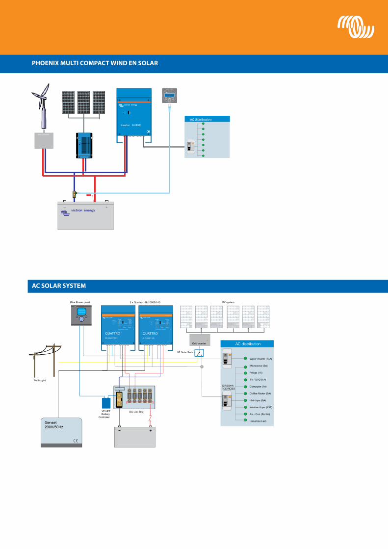
PhOEnix MULti cOMPAct WinD En sOLAR
Ac sOLAR systEM
BMV-602 battery monitor
SETUP
+-
SELECT
PHOENIX MULTICOMPACT MARINE 5
AC distribution Inverter 24/8000
mains
charger
failure
WIND CONVERTER
Bat. Select
CHG.MODE
POWER
LOAD BATTERY PV
- + - + - +
Type Module Size Glass size Weight
Electrical data under STC (1)
NominalPower
Max-PowerVoltage
Max-PowerCurrent
Open-CircuitVoltage
Short-circuitCurrent
PMPP VMPP IMPP Voc Isc
Module MM MM KG W V A V A
BSP30-12 532x418x23 527x413 3 30 18 1.66 21.6 1.83
BSP50-12 810x534x35 804x528 6.5 50 18 2.78 21.6 3.05
BSP80-12 1196x534x35 1189x528 8 80 18 4.44 21.6 4.88
BSP130-12 1456x666x35 1450x660 13 130 18 7.23 21.6 7.94
BSP180-12 1580x808x35 1574x802 15 180 36 4.95 43.2 5.45
BSP280-12 1930x980x50 1924x974 19 280 36 7.78 43.2 8.55
INVERTER
Module BSP30-12 BSP50-12 BSP80-12 BSP130-12 BSP130-12 BSP280-24
Nominal Power (±3% tolerance) 30W 50W 80W 130W 180W 280W
Cell type Monocrystalline Polycrystalline Monocrystalline Polycrystalline Monocrystalline Monocrystalline
Number of cells in series 36 72
Maximum system voltage (V) 1000V
Temperature coefficient of Isc (%) +0.06/°C +0.06/°C +0.06/°C +0.06/°C +0.06/°C +0.06/°C
Temperature coefficient of Voc (%) -0.35/°C -0.35/°C -0.35/°C -0.35/°C -0.35/°C -0.35/°C
Temperature coefficient of -0.47/°C -0.47/°C -0.47/°C -0.47/°C -0.47/°C -0.47/°C
Temperature coefficient of IMPP +0.06/°C +0.06/°C +0.06/°C +0.06/°C +0.06/°C +0.06/°C
Temperature coefficient of VMPP -0.34/°C -0.34/°C -0.34/°C -0.34/°C -0.34/°C -0.34/°C
Temperature Range -40°C to +80°C -40°C to +80°C
Surface Maximum Load Capacity 200kg/m²
Allowable Hail Load Steel ball Steel ball (weight 227g, diameter 25mm) fall down from 1m height
Junction Box Type PV-RH0301 PV-RH0301
Connector Type PV-ST01/M PV-ST01/F
Length of Cables 900mm 900mm
Output tolerance +/-3% +/-3%
Frame Aluminium
Product warranty 2 years
Warranty on electrical performance 10 years 90% + 15 years 80% of power output
Smallest packaging unit 2 panels
Quantity per pallet 88 panels 44 panels 44 panels 40 panels 52 panels 36 panels
1) STC (Standard Test Conditions): 1000W/m2, 25ºC, AM (Air Mass) 1.5

WinD En sOLAR sOLUtiOns
sPEciFicAtiOns OF thE sOLARsWitch
Protected loads
Unprotected loads
Public grid
Solar panel
Grid inverter
water heater
1.Alarm 2.Genset start 3.Load shedding
1. 2. 3.
VE.BUS mains multi
solar programmable relays
SolarSwitch
When the public grid is available, the Victron SolarSwitch will connect the solar inverter directly to the grid.If the grid fails, the power from the solar inverter will be redirected to the output of the MultiPlus. The MultiPlus replaces the grid and will balance the power mismatch between the load and the solar inverter. A power shortage will be supplemented by the MultiPlus, discharg-ing the battery, and excess power will be used to recharge the battery.Once the batteries are fully charged, the excess power can be redirected to a water heater (relay not shown), or a dump load (not shown), or the grid inverter can be stopped by slightly changing the output frequency of the MultiPlus (this is a standard feature of the MultiPlus).In order to prevent the batteries from discharging completely in case of insufficient solar power, some or all loads can be can be shut down with programmable relays available on the SolarSwitch (not shown).
SolarSwitch
AC inputs (Mains, MultiPlus/Quattro and Solar) Input voltage range: 187-265 VAC Input frequency: 45 – 65 Hz
Maximum switch through current (A) 25A
Maximum power consumption (W) < 4W
GENERAL
Auxiliary programmable Relay (3X) (1) Max load: 8A 250VAC
Status LED 1 Blue / 1 Yellow / 1 Red
Common Characteristics Operating temp.: -20 to +50°C Humidity (non condensing) : max 95%
ENCLOSURE
Common Characteristics Material & Colour: Housing polyamide 6.6 / greenCover unbreakable polycarbonate / Transparent Protection: IP 20
230 V AC-connection Screw terminals 5.2mm² (10 AWG)
Auxiliary relay connection Screw terminals 2.5mm² (19 AWG)
Weight (grams) 750
Dimensions (hxwxd in mm) 88 x 215 x 110
STANDARDS
Safety EN 60335-1, EN 60335-2-29
Emission / Immunity EN55014-1, EN 55014-2, EN 61000-3-3
1) Three programmable relays Can be programmed with VEConfigure Application examples: Alarm, generator start or load shedding functionAC rating: 230V/4A DC rating: 4A up to 35VDC, 1A up to 60VDC
nO-BREAk BAck-UP FOR gRiD cOnnEctED sOLAR systEM

POWER cOntROL ©
- Low cost PWM controller.- internal temperature sensor.- three stage battery charging (bulk, absorption, float).- Protected against over current.- Protected against short circuit.- Protected against reverse polarity connection of the solar panels and/or battery.- With low voltage load disconnect output.
Battery charger reduces its output, if required, to avoid overload of supply when system consumption is high.
BLUEsOLAR 12/24-10 10A At 12V OR 24V
BLUEsOLAR DUO 12/24-20 20A At 12V OR 24V
BLUEsOLAR chARgE cOntROLLERs
- PWM controller.- charges two separate batteries. For example the starter battery and the service battery of a boat or mobile home.- Programmable charge current ratio (standard setting: equal current to both batteries).- charge voltage settings for three battery types (gel, AgM and Flooded).- internal temperature sensor and optional remote temperature sensor.- Protected against over current.- Protected against short circuit.- Protected against reverse polarity connection of the solar panels and/or battery.
BLUEsOLAR MPPt 12/24-40 40A At 12V OR 24V
- Maximum Power Point tracking (MPPt) controller. increases charge current by up to 30% compared to a PWM controller.- charge voltage settings for eight battery types, plus two equalize settings.- Remote temperature sensor.- Protected against over current.- Protected against short circuit.- Protected against reverse polarity connection of the solar panels and/or battery.- With low voltage load disconnect output.
BLUESOLAR MPPT 12/24-40
BLUESOLAR 12/24-10
BLUESOLAR DUO 12/24-20
BLUE sOLAR chARgE cOntROLLERs

Victron Energy B.V. / De Paal 351351 JG Almere / The NetherlandsPhone: +31 (0)36 535 97 00 Fax: +31 (0)36 535 97 40e-mail: [email protected]
SAL064120020 - 00 - 1004
Related Documents