AUTOMOBILE ENGINEERING – I (15MET361) PRASHANTH KUMAR S PRABHU K S ASSISTANT PROFESSORS DEPARTMENT OF MECHANICAL ENGINEERING, NCET, BENGALURU Page 1 MODULE III SUPER CHARGERS AND TURBO CHARGERS Superchargers and Turbochargers: Naturally aspirated engines, Forced induction, Types of superchargers, Turbocharger construction and operation, Intercooler, Turbocharger lags. 3.1 Introduction to Naturally Aspirated Engine: The power developed by a naturally aspirated engine depends upon, i) Amount of air introduced into cylinder per cycle ii) Degree of utilization of the inducted air iii) The engine speed and thermal efficiency iv) Quantity of fuel admitted and its combustion characteristics. By increasing engine speed or by increasing air density at the inlet, it is possible to increase the amount of air inducted in to engine cylinder per unit time. As engine speed increases, inertia load increases and this calls for rigid and robust engine to with stand stresses. Also higher engine speed causes decrease in volumetric efficiency, higher friction and increased bearing loads. The method of increasing the inlet air density is called super charging. This increases power output of the engine. The super charging is achieved by supply in air or air- fuel mixture at a pressure higher than the pressure at which the engine naturally aspirates air. This increases air density and hence mass of air or air fuel mixture inducted for the same swept volume and there by increases power output of the engine. A device called super charger is used to increase the pressure of air. The power output of the engine can also be increased by increasing compression ratio. The high compression ratio results in increase of Brake mean effective pressure and the maximum cylinder pressure. For a given maximum cylinder pressure more power can be obtained by super charging compared to that obtained by raising compression ratio. The increase in compression ratio also increases exhaust temperature and results in higher thermal loads. Turbo charging uses energy of exhaust gases to drive a turbine that increases inlet air density.

Welcome message from author
This document is posted to help you gain knowledge. Please leave a comment to let me know what you think about it! Share it to your friends and learn new things together.
Transcript

AUTOMOBILE ENGINEERING – I (15MET361) PRASHANTH KUMAR S
PRABHU K S
ASSISTANT PROFESSORS
DEPARTMENT OF MECHANICAL ENGINEERING, NCET, BENGALURU Page 1
MODULE III
SUPER CHARGERS AND TURBO CHARGERS
Superchargers and Turbochargers:
Naturally aspirated engines,
Forced induction,
Types of superchargers,
Turbocharger construction and
operation,
Intercooler,
Turbocharger lags.
3.1 Introduction to Naturally Aspirated Engine:
The power developed by a naturally aspirated engine depends upon,
i) Amount of air introduced into cylinder per cycle
ii) Degree of utilization of the inducted air
iii) The engine speed and thermal efficiency
iv) Quantity of fuel admitted and its combustion characteristics.
By increasing engine speed or by increasing air density at the inlet, it is possible to
increase the amount of air inducted in to engine cylinder per unit time. As engine speed
increases, inertia load increases and this calls for rigid and robust engine to with stand
stresses. Also higher engine speed causes decrease in volumetric efficiency, higher friction
and increased bearing loads.
The method of increasing the inlet air density is called super charging. This
increases power output of the engine. The super charging is achieved by supply in air or air-
fuel mixture at a pressure higher than the pressure at which the engine naturally aspirates air.
This increases air density and hence mass of air or air fuel mixture inducted for the same
swept volume and there by increases power output of the engine. A device called super
charger is used to increase the pressure of air.
The power output of the engine can also be increased by increasing compression
ratio. The high compression ratio results in increase of Brake mean effective pressure and
the maximum cylinder pressure. For a given maximum cylinder pressure more power can be
obtained by super charging compared to that obtained by raising compression ratio.
The increase in compression ratio also increases exhaust temperature and results in
higher thermal loads. Turbo charging uses energy of exhaust gases to drive a turbine that
increases inlet air density.
AUTOMOBILE ENGINEERING – I (15MET361) PRASHANTH KUMAR S
PRABHU K S
ASSISTANT PROFESSORS
DEPARTMENT OF MECHANICAL ENGINEERING, NCET, BENGALURU Page 2
3.2 Superchargers and Turbochargers:
A supercharger is an air compressor that increases the pressure or density of air
supplied to an internal combustion engine. This gives each intake cycle of the engine more
oxygen, letting it burn more fuel and do more work, thus increasing power. Power for the
supercharger can be provided mechanically by means of a belt, gear, shaft, or chain connected
to the engine's crankshaft.
When power is provided by a turbine powered by exhaust gas, a supercharger is
known as a turbo supercharger– typically referred to simply as a turbocharger or just turbo.
Common usage restricts the term supercharger to mechanically driven units.
3.2.1 General Overview of Superchargers:
Superchargers are an external mechanism driven off the engine's auxiliary drive belt.
The mechanism can work in many fashions, but all have the same basic effect: to increase the
force on the incoming air to the engine. Since superchargers are belt-driven, they do create
small amounts of parasitic drag on the engine, however the effects of the supercharger
greatly outweigh the drag.
Generally, superchargers work with gear ratios to create the desired speed of the
impeller (or other air-moving mechanism). If fewer boosts is desired, a larger drive-pulley
can be interchanged onto the supercharger. If greater boost is desired, a smaller pulley is
used. However, boost levels can be controlled in other ways too. A waste gate or blow-off-
valve can be used in conjunction with a correctly sized pulley to have great control over
boost levels.
The points to be noted during super charging are
1. It increases power output of the engine
2. Super charging results in higher forces. The engine should be designed to with stand these
higher forces.
3. The power required for air compression has to be taken from engine itself. But net power
output will be more than power output without super charging for the same capacity.
4. The higher pressure and temperature may lead to detonation. Therefore fuel with better
antiknock characteristics is required.

AUTOMOBILE ENGINEERING – I (15MET361) PRASHANTH KUMAR S
PRABHU K S
ASSISTANT PROFESSORS
DEPARTMENT OF MECHANICAL ENGINEERING, NCET, BENGALURU Page 3
3.3 Forced induction:
Forced induction is the process of delivering compressed air to the intake of an
internal combustion engine. A forced induction engine uses a gas compressor to increase the
pressure, temperature and density of the air. An engine without forced induction is considered
a naturally aspirated engine. Forced induction is used in the automotive and aviation industry
to increase engine power and efficiency. A forced induction engine is essentially two
compressors in series. The compression stroke of the engine is the main compression that
every engine has an additional compressor feeding into the intake of the engine makes it a
forced induction.
A compressor feeding pressure into another greatly increases the total compression
ratio of the entire system. This intake pressure is called boost. This particularly helps aviation
engines, as they need to operate at high altitude.
Higher compression engines have the benefit of maximizing the amount of useful
energy extracted per unit of fuel. Therefore, the thermal efficiency of the engine is increased
in accordance with the vapor power cycle analysis of the second law of thermodynamics. The
reason all engines are not higher compression is because for any given octane, the fuel will
prematurely detonate with a higher than normal compression ratio.
This is called pre-ignition, detonation or knocks and can cause severe engine damage.
High compression on a naturally aspirated engine can reach the detonation threshold fairly
easily. However, a forced induction engine can have a higher total compression without
detonation because the air charge can be cooled after the first stage of compression, using an
intercooler.
One of the primary concerns in internal combustion emissions is a factor called the
NOx fraction, or the amount of nitrogen/oxygen compounds the engine produces. This level is
government regulated for emissions as commonly seen at inspection stations. High
compression causes high combustion temperatures. High combustion temperatures lead to
higher NOx emissions, thus forced induction can give higher NOx fractions.
3.4 Superchargers:
A supercharger is an air compressor that increases the pressure or density of air
supplied to an internal combustion engine. This gives each intake cycle of the engine more
oxygen, letting it burn more fuel and do more work, thus increasing power. Power for the
supercharger can be provided mechanically by means of a belt, gear, shaft, or chain connected
to the engine's crankshaft.
AUTOMOBILE ENGINEERING – I (15MET361) PRASHANTH KUMAR S
PRABHU K S
ASSISTANT PROFESSORS
DEPARTMENT OF MECHANICAL ENGINEERING, NCET, BENGALURU Page 4
When power is provided by a turbine powered by exhaust gas, a supercharger is
known as a turbo supercharger– typically referred to simply as a turbocharger or just turbo.
Common usage restricts the term supercharger to mechanically driven units.
3.4.1 Objectives of Super Charging
Mainly super charging is done to induct more amount of air into cylinder per unit time
and hence to burn more amount of fuel to increase power output.
Following are the objectives of supercharging
1. To obtain better performance from the existing engine.
2. To compensate for loss of power due to high altitudes for air craft engines.
3. For a given weight and bulk of the engine, super-charging increases power output.
4. This is important in air craft, marine and automotive engines where weight and space
are considered.
3.4.2 ADVANTAGES AND DISADVANTAGES OF SUPER CHARGING
Advantages
1. Power output of the engine can be increased
2. More quantity of charge can be inducted in to engine cylinder
3. Better atomization of fuel is possible
4. Better mixing of air and fuel can be obtained
5. Better scavenging of exhaust gases is possible
6. Torque is improved for whole speed range and better torque at low speeds
7. Faster acceleration of the engine is possible
8. The specific fuel consumption is lowered slightly
9. A better mechanical efficiency and efficient combustion is possible
10 In CI engines, exhaust smoke is reduced
Disadvantages
1. Detonation tendency increases in SI engines
2. Heat losses due to turbulence and thermal stresses are more
3. The valve overlap period increases up to 60° of crank angle
4. Better lubrication is required
5. Better cooling of piston and valves is required
6. It increases cost of the engine
AUTOMOBILE ENGINEERING – I (15MET361) PRASHANTH KUMAR S
PRABHU K S
ASSISTANT PROFESSORS
DEPARTMENT OF MECHANICAL ENGINEERING, NCET, BENGALURU Page 5
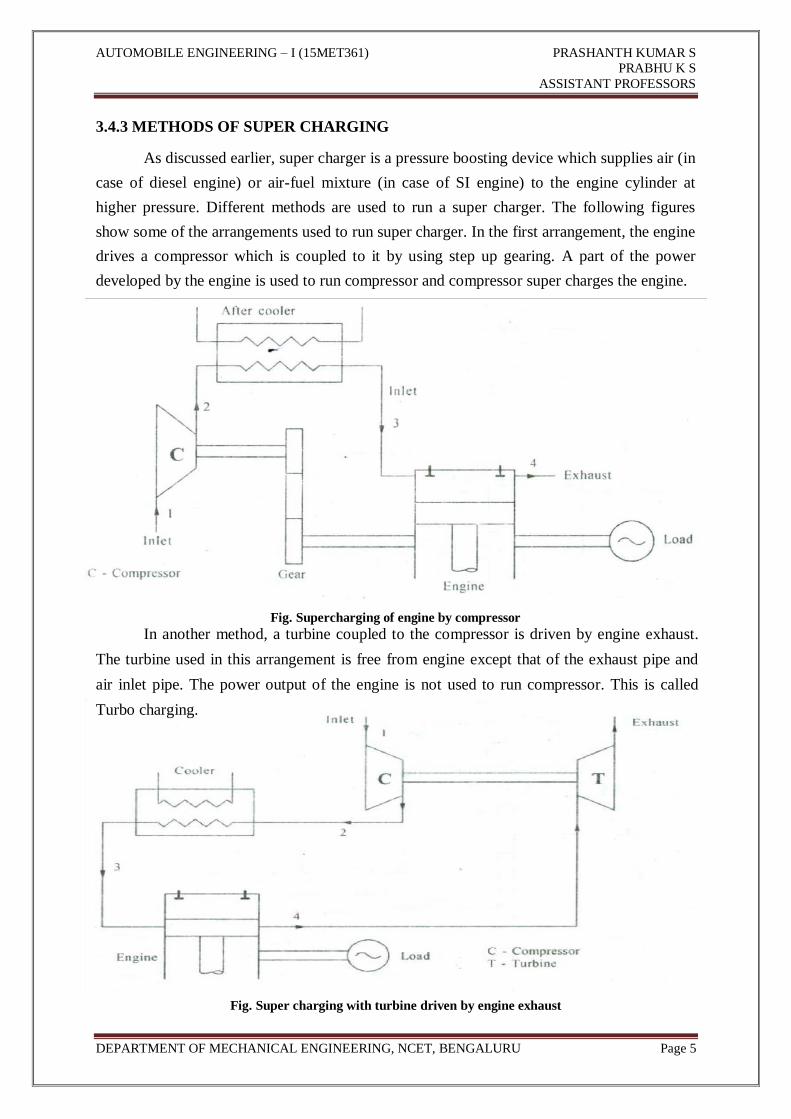
3.4.3 METHODS OF SUPER CHARGING
As discussed earlier, super charger is a pressure boosting device which supplies air (in
case of diesel engine) or air-fuel mixture (in case of SI engine) to the engine cylinder at
higher pressure. Different methods are used to run a super charger. The following figures
show some of the arrangements used to run super charger. In the first arrangement, the engine
drives a compressor which is coupled to it by using step up gearing. A part of the power
developed by the engine is used to run compressor and compressor super charges the engine.
Fig. Supercharging of engine by compressor In another method, a turbine coupled to the compressor is driven by engine exhaust.
The turbine used in this arrangement is free from engine except that of the exhaust pipe and
air inlet pipe. The power output of the engine is not used to run compressor. This is called
Turbo charging.
Fig. Super charging with turbine driven by engine exhaust
AUTOMOBILE ENGINEERING – I (15MET361) PRASHANTH KUMAR S
PRABHU K S
ASSISTANT PROFESSORS
DEPARTMENT OF MECHANICAL ENGINEERING, NCET, BENGALURU Page 6
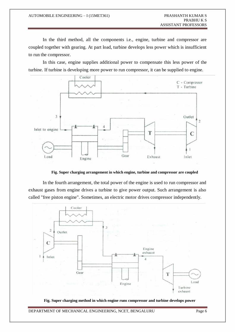
In the third method, all the components i.e., engine, turbine and compressor are
coupled together with gearing. At part load, turbine develops less power which is insufficient
to run the compressor.
In this case, engine supplies additional power to compensate this less power of the
turbine. If turbine is developing more power to run compressor, it can be supplied to engine.
Fig. Super charging arrangement in which engine, turbine and compressor are coupled
In the fourth arrangement, the total power of the engine is used to run compressor and
exhaust gases from engine drives a turbine to give power output. Such arrangement is also
called "free piston engine". Sometimes, an electric motor drives compressor independently.
Fig. Super charging method in which engine runs compressor and turbine develops power
AUTOMOBILE ENGINEERING – I (15MET361) PRASHANTH KUMAR S
PRABHU K S
ASSISTANT PROFESSORS
DEPARTMENT OF MECHANICAL ENGINEERING, NCET, BENGALURU Page 7
3.5 Types of superchargers:
Usually reciprocating compressors, displacement type rotary blowers, centrifugal
compressors are used to supercharge engine for various applications. If engine crank shaft
drives super charger, then it is called mechanical super charger. If the super charger is driven
by a gas turbine which runs on exhaust gases from the engine, then it is called Turbo-
charger.
The main types of super charger are,
1) Centrifugal type
2) Roots blower
3) Vane blower.
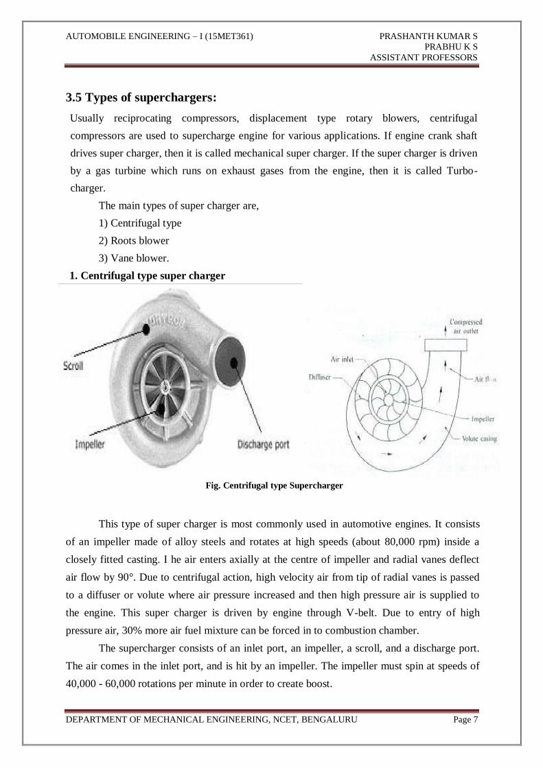
1. Centrifugal type super charger
Fig. Centrifugal type Supercharger
This type of super charger is most commonly used in automotive engines. It consists
of an impeller made of alloy steels and rotates at high speeds (about 80,000 rpm) inside a
closely fitted casting. I he air enters axially at the centre of impeller and radial vanes deflect
air flow by 90°. Due to centrifugal action, high velocity air from tip of radial vanes is passed
to a diffuser or volute where air pressure increased and then high pressure air is supplied to
the engine. This super charger is driven by engine through V-belt. Due to entry of high
pressure air, 30% more air fuel mixture can be forced in to combustion chamber.
The supercharger consists of an inlet port, an impeller, a scroll, and a discharge port.
The air comes in the inlet port, and is hit by an impeller. The impeller must spin at speeds of
40,000 - 60,000 rotations per minute in order to create boost.

AUTOMOBILE ENGINEERING – I (15MET361) PRASHANTH KUMAR S
PRABHU K S
ASSISTANT PROFESSORS
DEPARTMENT OF MECHANICAL ENGINEERING, NCET, BENGALURU Page 8
At idle speeds, the impeller does not have enough rotational speed to produce any
boost. The impeller utilizes centrifugal forces in order to produce boost.
The impeller is the integral part of the centrifugal supercharger (depicted as black
fins). As the air comes in at the center of the compressor blades, the impeller grabs the
incoming air from the inlet port (1).
Since the impeller is turning at tens-of-thousands of revolutions per minute, the air is
naturally thrown back and towards the outskirts of the fins due to centrifugal forces created by
its rotational inertia (2 &3).
"At the outside of the blades, a "scroll" is waiting to catch the air molecules. Just
before entering the scroll, the air molecules are forced to travel through a venturi (depicted as
the larger grey circle), which creates the internal compression, as the air travels around the
scroll (4).
The diameter of the scroll increases, which slows the velocity of the air, but further
increases its pressure (5)"
While a centrifugal supercharger is capable of very high levels of boost and high levels of
horsepower increase, the boost doesn't occur until high RPMs are reached (normally the
supercharger starts creating boost around 3000 RPMs).
Advantages & Disadvantages of Centrifugal Super Charger 1. Low initial cost, less power requirement and high conversion efficiency
2. It requires less maintenance and handles any quantity of air
3. It requires more space due to larger impeller
AUTOMOBILE ENGINEERING – I (15MET361) PRASHANTH KUMAR S
PRABHU K S
ASSISTANT PROFESSORS
DEPARTMENT OF MECHANICAL ENGINEERING, NCET, BENGALURU Page 9
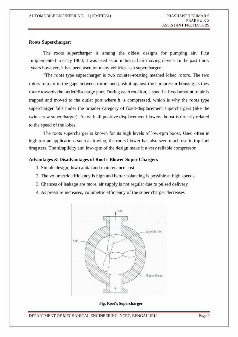
Roots Supercharger:
The roots supercharger is among the oldest designs for pumping air. First
implemented in early 1900, it was used as an industrial air-moving device. In the past thirty
years however, it has been used on many vehicles as a supercharger.
"The roots type supercharger is two counter-rotating meshed lobed rotors. The two
rotors trap air in the gaps between rotors and push it against the compressor housing as they
rotate towards the outlet/discharge port. During each rotation, a specific fixed amount of air is
trapped and moved to the outlet port where it is compressed, which is why the roots type
supercharger falls under the broader category of fixed-displacement superchargers (like the
twin screw supercharger). As with all positive displacement blowers, boost is directly related
to the speed of the lobes.
The roots supercharger is known for its high levels of low-rpm boost. Used often in
high torque applications such as towing, the roots blower has also seen much use in top-fuel
dragsters. The simplicity and low-rpm of the design make it a very reliable compressor
Advantages & Disadvantages of Root's Blower Super Chargers
1. Simple design, low capital and maintenance cost
2. The volumetric efficiency is high and better balancing is possible at high speeds.
3. Chances of leakage are more, air supply is not regular due to pulsed delivery
4. As pressure increases, volumetric efficiency of the super charger decreases
Fig. Root’s Supercharger

AUTOMOBILE ENGINEERING – I (15MET361) PRASHANTH KUMAR S
PRABHU K S
ASSISTANT PROFESSORS
DEPARTMENT OF MECHANICAL ENGINEERING, NCET, BENGALURU Page 10
Vane Blowers
It is a positive displacement rotary type super charger. This consists of a cylindrical
casing, a rotor with four slots; remain in contact with casing at least at one point all the time.
The rotor is eccentrically mounted and vanes slides in and out of the rotor slots in radial
direction. The air is induced in the space between the blades due to outward movement of
vanes, which increases the space between the blades.
When the space reduces near the outlet of super charger, it discharges air. The space
between inner surface of body and drum decreases from inlet to outer side. The air which
enters at inlet, decreases in volume and hence pressure increases as air reaches outlet. The
movement of vanes causes flow pulsating and noisy.
Advantages & Disadvantages of Vane Blowers
1. Suitable for high capacity engines
2. High pressure ratio is possible and delivers large quantity of air.
3. Maintenance cost and power requirement is high.
4. The vanes rub against cylinders and wears out rapidly.
Fig. Vane supercharger
3.6 SUPER CHARGING LIMITS:
The parameters such as engine knock, thermal and mechanical loads limit the power
output of the engine. Usually in SI engines, knock limit are reached first, where as in diesel
engines thermal and mechanical loads limits are reached first. If supercharging is to be done
in an existing engine, it is necessary to analyze the factors that limit the extent of super
charging. This in turn depends up on engine's ability to with stand gas loading, thermal
stresses, durability, reliability, fuel economy etc.

AUTOMOBILE ENGINEERING – I (15MET361) PRASHANTH KUMAR S
PRABHU K S
ASSISTANT PROFESSORS
DEPARTMENT OF MECHANICAL ENGINEERING, NCET, BENGALURU Page 11
In SI engines, the extent of super charging is mainly limited by kriock. The super
charging reduces ignition delay and this result in engine knock at these high pressures.
Therefore increase in super charging pressure increases the tendency to detonate. Generally
for SI engines, super charging is employed only for air craft and racing car engines. The
super charger pressure is in the range of 1.3 to-1.5 bar, corresponds to 30 to 50% super
charging.
In CI engines, super charging limits are not due to combustion. The engine runs
better, smoother and quieter due to decrease in ignition delay at high super charging pressure
and temperature. But the degree of super charging is limited by thermal and mechanical load
on the engine and mainly depends on the type of super charger used and engine design. Also
the engine reliability decreases at maximum cylinder pressure, this increases heat release rate
and hence thermal load on the engine. For intake pressures less than 1.5 atm, the cost of super
charging is not justified.
3.6 Turbocharger construction and operation:
Turbochargers are a type of superchargers. It effectively 'charges' the incoming air,
which is the definition of supercharging. The turbo differs from a supercharger in that it
derives its power from a different source than previously described designs. The previous
designs received power from the driveshaft of the engine. Turbochargers derive their power
from exhaust gasses.
Turbochargers use the power of the exhaust, much like a hydroelectric dam converts
power from the water into mechanical energy. A hydroelectric dam sends water through a
hydroelectric turbine. The turbine design redirects the flow of the water into a circle which is
caught by fins/blades. The water turns these blades, which turns a driveshaft. When the water
has released most all of its energy to the fins, the water then exits the turbine through a port at
the center.
Turbochargers in cars act nearly the same way except the water is replaced with
exhaust from the engine. The drive shaft, in-turn, powers a centrifugal supercharger.
Turbochargers are very efficient, because they do not leech off of the engine's power. The
turbo has some downsides however. Boost cannot be controlled by simply changing a pulley.
Boost must be controlled by a wastage or blow off valve. Another downside to a turbocharger
is the superheating of the intake air. Since the turbine must be run by hot exhaust gasses, the
heat transfers via conduction to the compressor.

AUTOMOBILE ENGINEERING – I (15MET361) PRASHANTH KUMAR S
PRABHU K S
ASSISTANT PROFESSORS
DEPARTMENT OF MECHANICAL ENGINEERING, NCET, BENGALURU Page 12
The compressor becomes superheated, and therefore heats the incoming air to the
engine. This can be counteracted by implementing an intercooler.
The other main con of a turbocharger is something called turbo-lag. Turbo-lag is the
time it takes for the turbo to spool up and produce power. Since an engine does not create
large amounts of exhaust in low RPMs, the turbo creates small amounts of boost, and must
have time to gain rotational inertia from the exhaust.
Despite the added downsides, turbochargers can create very large amounts of horsepower
and is able to deliver added torque that a regular centrifugal supercharger lacks.
Fig. Exhaust turbo charging of a single cylinder engine
Working:
The turbine uses energy from the exhaust gases to convert heat energy into rotational
motion. This rotational motion of turbine drives the compressor, which draws in ambient air
from the surrounding and pumps compressed air with high density and pressure into the
intake manifold.
AUTOMOBILE ENGINEERING – I (15MET361) PRASHANTH KUMAR S
PRABHU K S
ASSISTANT PROFESSORS
DEPARTMENT OF MECHANICAL ENGINEERING, NCET, BENGALURU Page 13
The exhaust gas enters the turbine inlet side of the turbocharger through a pressurized
chamber and a series of filters. The nozzle blade rings concentrates the exhaust gas on to the
turbine wheel. The movement of the turbine wheel rotates the shaft which in turn rotates the
impellor of the compressor. A part of this air goes to the labyrinths seal from the outlet side of
the turbine.
As the impeller rotates, air is sucked in through the center of the impeller and due to
the heavy rotational movement, experiences circumferential velocity which pushes it
outwards. A radial velocity is gained which pushes the air further outwards on to the inducer.
An additional resultant velocity is gained due to the accurately designed inducer inlet
angle which gives maximum compressor efficiency. Excessive pressure leads to spoiling or
fouling of the impeller and inducer surfaces. These results in change in angle of incidence and
thus drop in efficiency.
All heavy fuel engines are subjected to heavy load variations which results in
fluctuation of exhaust gas pressure. A prolonged fluctuation in pressure leads to detrimental
effects on the internal parts of the compressor. For this reason, constant pressure chambers are
provided in most of the engines. The exhaust gas, instead of directly entering from the engine,
first goes to the pressure chamber and from there it is circulated to the turbine at constant
pressure. This reduces the excessive stress that gets created on the shaft bearing and sealing.
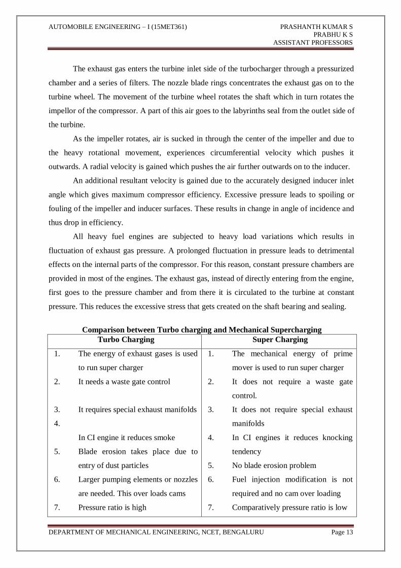
Comparison between Turbo charging and Mechanical Supercharging
Turbo Charging Super Charging
1. The energy of exhaust gases is used
to run super charger
2. It needs a waste gate control
3. It requires special exhaust manifolds
4.
In CI engine it reduces smoke
5. Blade erosion takes place due to
entry of dust particles
6. Larger pumping elements or nozzles
are needed. This over loads cams
7. Pressure ratio is high
1. The mechanical energy of prime
mover is used to run super charger
2. It does not require a waste gate
control.
3. It does not require special exhaust
manifolds
4. In CI engines it reduces knocking
tendency
5. No blade erosion problem
6. Fuel injection modification is not
required and no cam over loading
7. Comparatively pressure ratio is low
AUTOMOBILE ENGINEERING – I (15MET361) PRASHANTH KUMAR S
PRABHU K S
ASSISTANT PROFESSORS
DEPARTMENT OF MECHANICAL ENGINEERING, NCET, BENGALURU Page 14
8. It is bulky and heavy
9. Easy scavenging
10. Poor response to load change
8. It is light and compact
9. Scavenging is difficult
10. Better response to load change
3.5.1 Limitations of turbo charging:
1) The turbo charging needs special exhaust manifolds
2) Larger pumping elements or nozzles are required to inject more fuel per unit time.
This over loads cams and other components.
3) The turbine blade efficiency is very sensitive to gas velocity
4) It is difficult to maintain satisfactory air charging over the complete operating range
of the engine.
3.6 Intercooler:
The air charge leaving the compressed air is at much higher temperature than ambient
conditions. The temperature of air increases further to 60-950
C due to super charging. When
this high temperature air expands, its density decreases and hence mass of air entering the
engine cylinder decreases. This decreases availability of oxygen required for complete
combustion. If additional hot air is supplied, it increases operating temperature of the engine.
Therefore an inter cooler or after cooler or charge cooling is used to overcome this difficulty.
The use of inter cooler cools the charge there by decreases temperature of air entering into
engine cylinder.
An intercooler is an integral part of most blown setups. The power that a non-
intercooled turbocharger created could be maximized by using an intercooler. An intercooler
can be compared to a radiator, yet for intake air, and not coolant fluid.
The intercooler fits on the intake tract to the engine from the supercharger. Generally
only centrifugal superchargers (turbochargers included) can be intercooled, due to their
mounting options. The intercooler dramatically cools the compressed air, and in effect, packs
the air closer together.
The intercooler obviously boosts the power of the engine by stuffing more oxygen into
the cylinders. The cylinders can therefore create a larger and more vigorous explosion, and
therefore produce more power. Intercoolers can come in two types: air-air, or air-water. Air-
air systems use ambient air to directly cool the pressurized air. Air-water systems first cool
water with the ambient air around the car, and is then filtered into an internal coolant system,
where the cooled water cools the charge-air.
AUTOMOBILE ENGINEERING – I (15MET361) PRASHANTH KUMAR S
PRABHU K S
ASSISTANT PROFESSORS
DEPARTMENT OF MECHANICAL ENGINEERING, NCET, BENGALURU Page 15
3.7 Turbocharger lags:
It is time period required for exhaust gases to accelerate the turbine and compressor. It
represents short delay period before the boost pressure increases.
Turbo lag is a unique phenomenon encountered in turbocharged internal combustion
engines, whereby an operator experiences a short delay in full engine response after pressing
the accelerator pedal. This occurs because a turbocharger relies on pressure from exhaust
gasses, and needs a short amount of time to generate the pressure needed — known as
spooling up. Turbo lag is considered a negative characteristic in automobiles, and one that
engineers strive to mitigate in a number of different ways.
To understand turbo lag, a working knowledge of how turbochargers work and why
they are used is helpful. The idea behind adding a turbo system to an engine is to augment the
power generated by the engine alone through simple combustion. This basic concept is known
as supercharging, of which turbo charging is but one variant.
A turbo works by using exhaust air to spin a turbine, which is attached to the same
shaft as a compressor. Compressed air created as the turbine spins the compressor is, in turn,
fed into the engine. This allows more horsepower to be generated by improving the engine's
volumetric efficiency, a trait based in part on the fundamental precept that the more oxygen in
a given volume of air, the more potential energy that volume has compared to alternatives like
belt-drive superchargers or simply increasing the displacement of an engine, turbo charging is
an attractive option.
This is because the proportion of horsepower a turbo creates, as compared to the
weight of its parts — a characteristic known as power to weight ratio is favorable compared
to these other options. Turbo are thus relatively common in gasoline engines, and almost
standard in mass-produced diesel engines, which are known as turbo diesels.
Turbo engines have been particularly embraced by several automobile manufacturers,
including Saab®, Mercedes Benz®, and Volkswagen®. The basic design of a turbocharger
consists of a metal — usually aluminum — center housing and hub rotating assembly
(CHRA), a turbine, a compressor, and a central shaft.

AUTOMOBILE ENGINEERING – I (15MET361) PRASHANTH KUMAR S
PRABHU K S
ASSISTANT PROFESSORS
DEPARTMENT OF MECHANICAL ENGINEERING, NCET, BENGALURU Page 16
QUESTIONS
1. Explain the purpose of super charging.
2. With neat sketch and explain any two types of super chargers.
3. Give the complete Comparison between mechanical supercharging and turbo
charging.
4. Distinguish between turbocharger and super charger.
5. What is turbo charger lag and explain how it can be controlled.
6. Explain different methods of supercharging.
7. What are the objectives of supercharging?
8. What are the advantages and disadvantages of supercharging?
9. With a neat sketch explain the various methods of supercharging.
10. Explain the types of supercharger.
11. What is supercharging limits?
12. Explain the principles of working of turbo charging.
13. Define intercooler, turbocharger lag.
14. Mention the limitations of turbo charging.
15. What is supercharging? Compare supercharged engines with naturally aspirated
engines.
16. Explain different methods of supercharging.
17. Sketch and explain turbo charging.
18. Give the objectives of supercharging and explain any two arrangements of
supercharging.
19. What is the need of turbo charging? Explain anyone method of turbo
charging giving its merits and demerits.
20. What are the objectives of supercharging?
21. What is the effect of super charging on the following parameters?
a) Power output
b) Mechanical efficiency
c) Fuel consumption.
22. With a neat sketch, explain centrifugal type supercharger.

AUTOMOBILE ENGINEERING – I (15MET361) PRASHANTH KUMAR S
PRABHU K S
ASSISTANT PROFESSORS
DEPARTMENT OF MECHANICAL ENGINEERING, NCET, BENGALURU Page 17
MODULE IV
IGNITION SYSTEMS Battery Ignition Systems,
Magneto Ignition System,
Transistor Assist Contacts.
Electronic Ignition,
Automatic Ignition Advance Systems
4.1 Introduction
We know that in case of Internal Combustion (IC) engines, combustion of air and fuel
takes place inside the engine cylinder and the products of combustion expand to produce
reciprocating motion of the piston. This reciprocating motion of the piston is in turn converted
into rotary motion of the crank shaft through connecting rod and crank. This rotary motion of
the crank shaft is in turn used to drive the generators for generating power. We also know that
there are 4-cycles of operations viz.: suction; compression; power generation and exhaust.
These operations are performed either during the 2-strokes of piston or during 4-strokes of
the piston and accordingly they are called as 2-stroke cycle engines and 4-stroke cycle engines.
In case of petrol engines during suction operation, charge of air and petrol fuel will be taken
in. During compression this charge is compressed by the upward moving piston. And just
before the end of compression, the charge of air and petrol fuel will be ignited by means of
the spark produced by means of for spark plug. And the ignition system does the function of
producing the spark in case of spark ignition engines.
Figure 4.1 shows atypical spark plug used with petrol engines. It mainly consists of a
central electrode and metal tongue. Central electrode is covered by means of porcelain
insulating material. Through the metal screw the spark plug is fitted in the cylinder head plug,
when the high tension voltage of the order of 30000 volts is applied across the spark
electrodes, current jumps from one electrode to another producing a spark.
AUTOMOBILE ENGINEERING – I (15MET361) PRASHANTH KUMAR S
PRABHU K S
ASSISTANT PROFESSORS
DEPARTMENT OF MECHANICAL ENGINEERING, NCET, BENGALURU Page 18
Whereas in case of diesel (Compression Ignition-CI) engines only air is taken in
during suction operation and in compressed during compression operation and just before the
end of compression, when diesel fuel is injected, it gets ignited due to heat of compression of
air. Once the charge is ignited, combustion starts and products of combustion expand, i.e. they
force the piston to move downwards i.e. they produce power and after producing the power
the gases are exhausted during exhaust operation.
4.1.1 Objectives After studying this unit, you should be able to
• Explain the different types of ignition systems,
• Differentiate between battery and magneto ignition system
• Know the drawbacks of conventional ignition system, and
• Appreciate the importance of ignition timing and ignition advance.
4.2 Ignition System Types
Basically Convectional Ignition systems are of 2 types:
1. Battery or Coil Ignition System,
2. Magneto Ignition System.
Both these conventional, ignition systems work on mutual electromagnetic induction
principle. Battery ignition system was generally used in 4-wheelers, but now-a-days it is more
commonly used in 2-wheelers also (i.e. Button start, 2-wheelers like Pulsar, Kinetic Honda;
Honda-Activa, Scooty, Fiero, etc.). In this case 6 V or 12 V batteries will supply necessary
current in the primary winding. Magneto ignition system is mainly used in 2-wheelers, kick start
engines. (Example, Bajaj Scooters, Boxer, Victor, Splendor, Passion, etc.). In this case magneto
will produce and supply current to the primary winding. So in magneto ignition system
magneto replaces the battery.
1. Battery or Coil Ignition System:
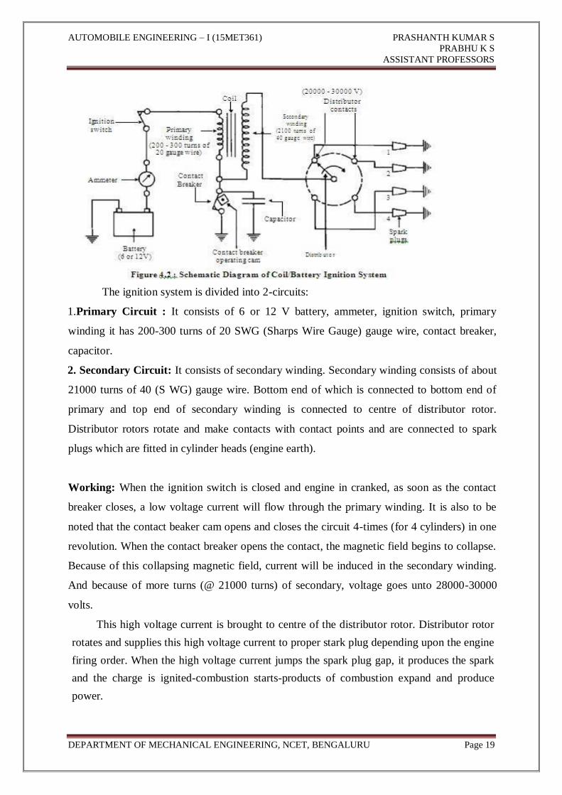
Figure 4.2 shows line diagram of battery ignition system for a 4-cylinder petrol
engine. It mainly consists of a 6 or 12 volt battery, ammeter, ignition switch, auto-transformer
(step up transformer), contact breaker, capacitor, distributor rotor, distributor contact points,
spark plugs, etc. Note that the Fig. 4.1 shows the ignition system for 4-cylinder petrol engine,
here there are 4-spark plugs and contact breaker cam has 4-corners. (If it is for 6cylinder
engine it will have 6-spark plugs and contact breaker cam will be a perfect hexagon).
AUTOMOBILE ENGINEERING – I (15MET361) PRASHANTH KUMAR S
PRABHU K S
ASSISTANT PROFESSORS
DEPARTMENT OF MECHANICAL ENGINEERING, NCET, BENGALURU Page 19
The ignition system is divided into 2-circuits:
1.Primary Circuit : It consists of 6 or 12 V battery, ammeter, ignition switch, primary
winding it has 200-300 turns of 20 SWG (Sharps Wire Gauge) gauge wire, contact breaker,
capacitor.
2. Secondary Circuit: It consists of secondary winding. Secondary winding consists of about
21000 turns of 40 (S WG) gauge wire. Bottom end of which is connected to bottom end of
primary and top end of secondary winding is connected to centre of distributor rotor.
Distributor rotors rotate and make contacts with contact points and are connected to spark
plugs which are fitted in cylinder heads (engine earth).
Working: When the ignition switch is closed and engine in cranked, as soon as the contact
breaker closes, a low voltage current will flow through the primary winding. It is also to be
noted that the contact beaker cam opens and closes the circuit 4-times (for 4 cylinders) in one
revolution. When the contact breaker opens the contact, the magnetic field begins to collapse.
Because of this collapsing magnetic field, current will be induced in the secondary winding.
And because of more turns (@ 21000 turns) of secondary, voltage goes unto 28000-30000
volts.
This high voltage current is brought to centre of the distributor rotor. Distributor rotor
rotates and supplies this high voltage current to proper stark plug depending upon the engine
firing order. When the high voltage current jumps the spark plug gap, it produces the spark
and the charge is ignited-combustion starts-products of combustion expand and produce
power.
AUTOMOBILE ENGINEERING – I (15MET361) PRASHANTH KUMAR S
PRABHU K S
ASSISTANT PROFESSORS
DEPARTMENT OF MECHANICAL ENGINEERING, NCET, BENGALURU Page 20
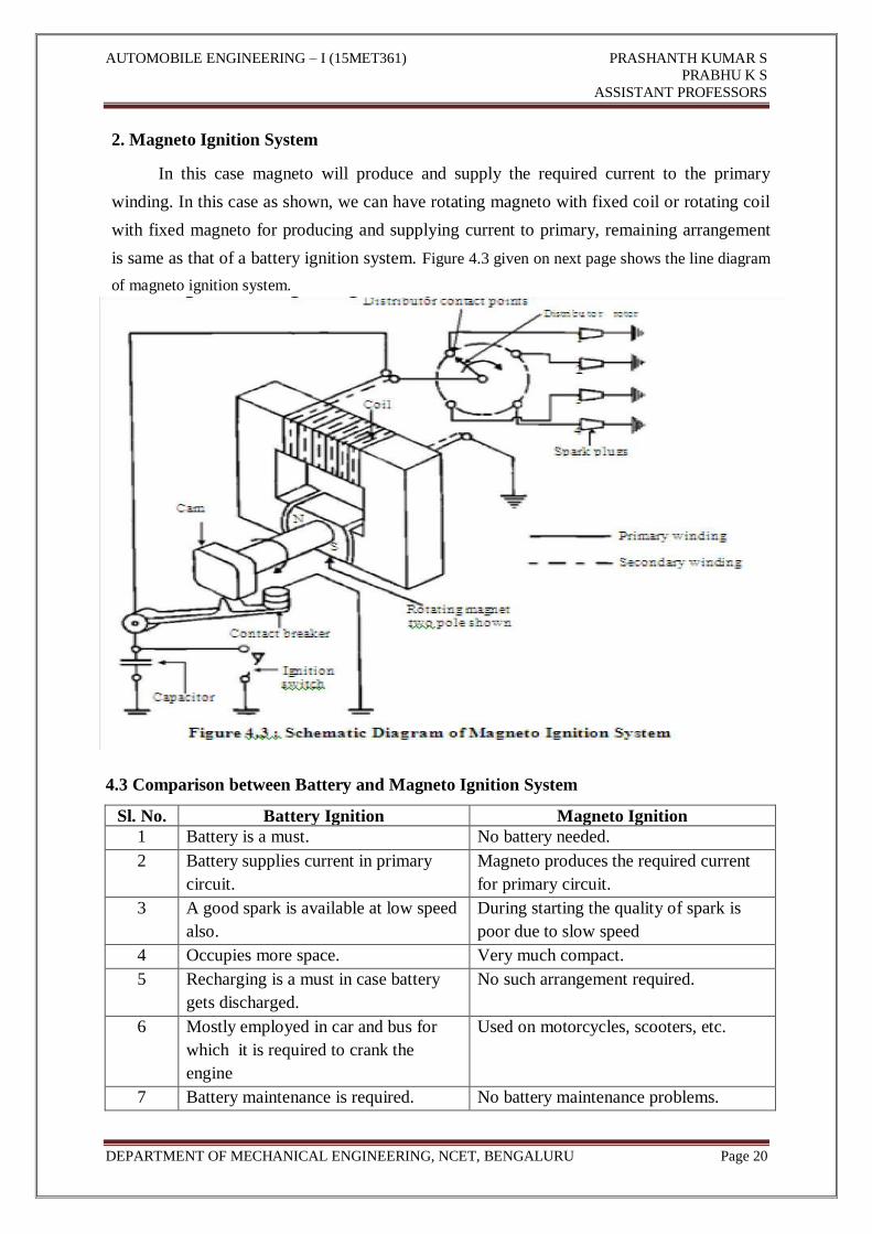
2. Magneto Ignition System
In this case magneto will produce and supply the required current to the primary
winding. In this case as shown, we can have rotating magneto with fixed coil or rotating coil
with fixed magneto for producing and supplying current to primary, remaining arrangement
is same as that of a battery ignition system. Figure 4.3 given on next page shows the line diagram
of magneto ignition system.
4.3 Comparison between Battery and Magneto Ignition System
Sl. No. Battery Ignition Magneto Ignition
1 Battery is a must. No battery needed.
2 Battery supplies current in primary
circuit.
Magneto produces the required current
for primary circuit.
3 A good spark is available at low speed
also.
During starting the quality of spark is
poor due to slow speed
4 Occupies more space. Very much compact.
5 Recharging is a must in case battery
gets discharged.
No such arrangement required.
6 Mostly employed in car and bus for
which it is required to crank the
engine
Used on motorcycles, scooters, etc.
7 Battery maintenance is required. No battery maintenance problems.
AUTOMOBILE ENGINEERING – I (15MET361) PRASHANTH KUMAR S
PRABHU K S
ASSISTANT PROFESSORS
DEPARTMENT OF MECHANICAL ENGINEERING, NCET, BENGALURU Page 21
Note: The Function of the capacitor is to reduce arcing at the contact breaker (CB) points.
Also when the CB opens the magnetic field in the primary winding begins to collapse. When
the magnetic field is collapsing capacitor gets fully charged and then it starts discharging and
helps in building up of voltage in secondary winding. Contact breaker cam and distributor
rotor are mounted on the same shaft. In 2-stroke cycle engines these are motored at the same
engine speed. And in 4-stroke cycle engines they are motored at half the engine speed.
4.4 Drawbacks (Disadvantages) Of Conventional Ignition Systems
Following are the drawbacks of conventional ignition systems:
1. Because of arcing, pitting of contact breaker point and which will lead to regular
maintenance problems.
2. Poor starting: After few thousands of kilometers of running, the timing becomes
inaccurate, which results into poor starting (Starting trouble).
3. At very high engine speed, performance is poor because of inertia effects of the
moving parts in the system.
4. Sometimes it is not possible to produce spark properly in fouled spark plugs.
In order to overcome these drawbacks Electronic Ignition system is used.
4.5 Advantages of Electronic Ignition System
Following are the advantages of electronic ignition system:
1. Moving parts are absent-so no maintenance.
2. Contact breaker points are absent-so no arcing.
3. Spark plug life increases by 50% and they can be used for about 60000 km without
any problem.
4. Better combustion in combustion chamber, about 90-95% of air fuel mixture is
burnt compared with 70-75% with conventional ignition system.
5. More power output.
6. More fuel efficiency.
4.6 Types of Electronic Ignition System
1. Capacitance Discharge Ignition system.
2. Transistorized system
3. Piezo-electric Ignition system
4. The Texaco Ignition system

AUTOMOBILE ENGINEERING – I (15MET361) PRASHANTH KUMAR S
PRABHU K S
ASSISTANT PROFESSORS
DEPARTMENT OF MECHANICAL ENGINEERING, NCET, BENGALURU Page 22
4.6.1 Capacitance Discharge Ignition System
It mainly consists of 6-12 V battery, ignition switch, DC to DC convertor, charging
resistance, tank capacitor, Silicon Controlled Rectifier (SCR), SCR-triggering device, step up
transformer, spark plugs. A 6-12 volt battery is connected to DC to DC converter i.e. power
circuit through the ignition switch, which is designed to give or increase the voltage to 250-
350 volts. This high voltage is used to charge the tank capacitor (or condenser) to this voltage
through the charging resistance.
The charging resistance is also so designed that it controls the required current in the
SCR Depending upon the engine firing order, whenever the SCR triggering device, sends a
pulse, then the current flowing through the primary winding is stopped. And the magnetic
field begins to collapse. This collapsing magnetic field will induce or step up high voltage
current in the secondary, which while jumping the spark plug gap produces the spark, and the
charge of air fuel mixture is ignited.
Figure 4.4 : Capacitance Discharge Ignition System
4.6.2 Transistorized Assisted Contact (TAC) Ignition System
Figure 4.5 shows the TAC system.

AUTOMOBILE ENGINEERING – I (15MET361) PRASHANTH KUMAR S
PRABHU K S
ASSISTANT PROFESSORS
DEPARTMENT OF MECHANICAL ENGINEERING, NCET, BENGALURU Page 23
Figure 4.5 : Transistorized Assisted Contact (TAC) Ignition System
Advantages
1. The low breaker-current ensures longer life.
2. The smaller gap and lighter point assembly increase dwell time minimize contact
bouncing and improve repeatability of secondary voltage.
3. The low primary inductance reduces primary inductance reduces primary current
drop-off at high speeds.
Disadvantages
1. As in the conventional system, mechanical breaker points are necessary for timing
the spark.
2. The cost of the ignition system is increased.
3. The voltage rise-time at the spark plug is about the same as before.
4.6.3 Piezo-electric Ignition System
The development of synthetic piezo-electric materials producing about 22 kV by
mechanical loading of a small crystal resulted in some ignition systems for single cylinder
engines. But due to difficulties of high mechanical loading need of the order of 500 kg timely
control and ability to produce sufficient voltage, these systems have not been able to come up.
4.6.4 The Texaco Ignition System
Due to the increased emphasis on exhaust emission control, there has been a sudden
interest in exhaust gas recirculation systems and lean fuel-air mixtures. To avoid the problems
of burning of lean mixtures, the Texaco Ignition system has been developed.
AUTOMOBILE ENGINEERING – I (15MET361) PRASHANTH KUMAR S
PRABHU K S
ASSISTANT PROFESSORS
DEPARTMENT OF MECHANICAL ENGINEERING, NCET, BENGALURU Page 24
It provides a spark of controlled duration which means that the spark duration in crank
angle degrees can be made constant at all engine speeds. It is a AC system. This system
consists of three basic units, a power unit, a control unit and a distributor sensor. This system
can give stable ignition up to A/F ratios as high as 24
4.7 Importance of Ignition Timing and Ignition Advance
Ignition timing is very important, since the charge is to be ignited just before (few
degrees before TDC) the end of compression, since when the charge is ignited, it will take
some time to come to the required rate of burning.
Ignition Advance
The purpose of spark advance mechanism is to assure that under every condition of
engine operation, ignition takes place at the most favorable instant in time i.e. most
favorable from a standpoint of engine power, fuel economy and minimum exhaust dilution.
By means of these mechanisms the advance angle is accurately set so that ignition occurs
before TDC point of the piston. The engine speed and the engine load are the control
quantities required for the automatic adjustment of the ignition timing. Most of the engines
are fitted with mechanisms which are integral with the distributor and automatically regulate
the optimum spark advance to account for change of speed and load. The two mechanisms
used are as follows,
(a) Centrifugal advance mechanism,
(b) Vacuum advance mechanism.
Centrifugal Advance Mechanism
The centrifugal advance mechanism controls the ignition timing for full- load
operation. The adjustment mechanism is designed so that its operation results in the desired
advance of the spark. The cam is mounted, movably, on the distributor shaft so that as the
speed increases, the flyweights which are swung farther and farther outward, shaft the cam in
the direction of shaft rotation.
As a result, the cam lobes make contact with the breaker lever rubbing block
somewhat earlier, thus shifting the ignition point in the early or advance direction. Depending
on the speed of the engine, and therefore of the shaft, the weights are swung outward a
greater or a lesser distance from the center. They are then held in the extended position, in a
state of equilibrium corresponding to the shifted timing angle, by a retaining spring which

AUTOMOBILE ENGINEERING – I (15MET361) PRASHANTH KUMAR S
PRABHU K S
ASSISTANT PROFESSORS
DEPARTMENT OF MECHANICAL ENGINEERING, NCET, BENGALURU Page 25
exactly balances the centrifugal force. The weights shift the cam either or a rolling contact or
sliding contact basis.
For this reasons we distinguish between the rolling contact type and the sliding
contact type of centrifugal advance mechanism. The beginning of the timing adjustment in
the range of low engine speeds and continues adjustment based on the full load curve are
determined by the size of the weights by the shape of the contact mechanisms (rolling or
sliding contact type), and by the retaining springs, all of which can be widely differing
designs. The centrifugal force controlled cam is fitted with a lower limit stop for purposes
of setting the beginning of the adjustment, and also with an upper limit stop to restrict the
greatest possible full load adjustment. A typical sliding contact type centrifugal advance
mechanism is shown in Figures 4.6(a) and (b).
Vacuum Advance Mechanism
Vacuum advance mechanism shifts the ignition point under partial load operation.
The adjustment system is designed so that its operation results in the prescribed partial load
advance curve. In this mechanism the adjustment control quantity is the static vacuum
prevailing in the carburetor, a pressure which depends on the position of the throttle valve at
any given time and which is at a maximum when this valve is about half open. This explains
the vacuum maximum.
The diaphragm of a vacuum unit is moved by changes in gas pressure. The position
of this diaphragm is determined by the pressure differential at any given moment between
the prevailing vacuum and atmospheric pressure. The beginning of adjustment is set by the
pre-established tension on a compression spring.
AUTOMOBILE ENGINEERING – I (15MET361) PRASHANTH KUMAR S
PRABHU K S
ASSISTANT PROFESSORS
DEPARTMENT OF MECHANICAL ENGINEERING, NCET, BENGALURU Page 26
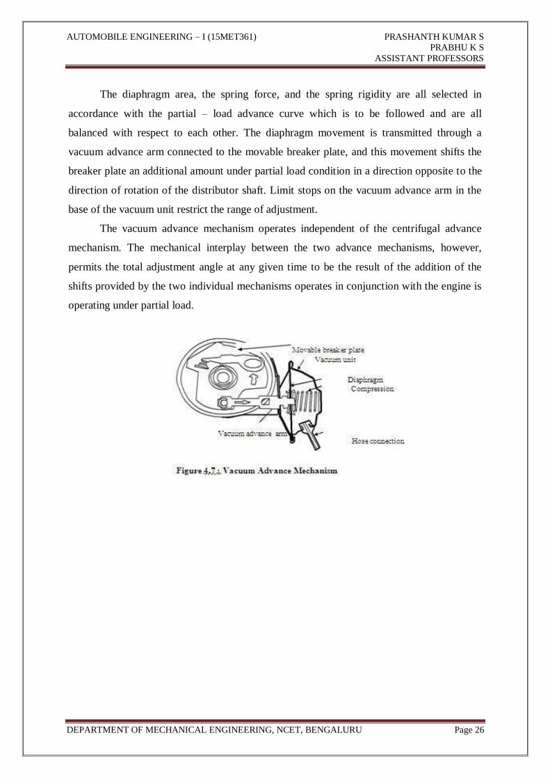
The diaphragm area, the spring force, and the spring rigidity are all selected in
accordance with the partial – load advance curve which is to be followed and are all
balanced with respect to each other. The diaphragm movement is transmitted through a
vacuum advance arm connected to the movable breaker plate, and this movement shifts the
breaker plate an additional amount under partial load condition in a direction opposite to the
direction of rotation of the distributor shaft. Limit stops on the vacuum advance arm in the
base of the vacuum unit restrict the range of adjustment.
The vacuum advance mechanism operates independent of the centrifugal advance
mechanism. The mechanical interplay between the two advance mechanisms, however,
permits the total adjustment angle at any given time to be the result of the addition of the
shifts provided by the two individual mechanisms operates in conjunction with the engine is
operating under partial load.

AUTOMOBILE ENGINEERING – I (15MET361) PRASHANTH KUMAR S
PRABHU K S
ASSISTANT PROFESSORS
DEPARTMENT OF MECHANICAL ENGINEERING, NCET, BENGALURU Page 27
QUESTIONS
1. Name the different types of ignition system.
2. What is the battery voltage generally used in automobile ignition system?
3. What is the voltage resulting the spark at the plug electrodes?
4. What are requirements of an ignition system?
5. Name the various components of Battery coil ignition system.
6. What is the function of an ignition coil?
7. What is low tension and high tension magneto?
8. Differentiate between battery and magneto coil ignition system.
9. What is ignition advance?
10. What is the purpose of providing ignition advance?
11. Name the various methods of ignition advance.
12. With sketch explain the working of centrifugal advance.
13. With sketch explain the working of vacuum advance.
14. Explain with a neat sketch, working of a battery ignition system
15. Explain the working of vacuum advance
16. What are the advantages of using an electronic ignition system?
17. Explain working of electronic ignition system with help of a sketch.
18. List the requirements of ignition system.
19. Compare battery and magneto ignition systems.
20. Give the requirements of ignition system and explain magneto ignition system with
sketch.
21. What is the need of electronic ignition system? Explain TAC electronic ignition
system.
22. Name the different types of ignition system? Explain with a neat sketch. Magneto
Ignition system.
23. What is an ignition advance? Explain with sketch the centrifugal ignition advance.
24. Explain the working of rotating armature type and rotating magneto ignition system.
25. Explain the purpose of providing ignition advance with the parameters that affects
ignition advance.
26. Draw a neat circuit diagram of battery ignition system and explain functions of
various devices in circuit.

AUTOMOBILE ENGINEERING – I (15MET361) PRASHANTH KUMAR S
PRABHU K S
ASSISTANT PROFESSORS
DEPARTMENT OF MECHANICAL ENGINEERING, NCET, BENGALURU Page 28
27. What are the requirements of ignition system?
28. With neat circuit diagram explain the principals of electronic ignition system.
29. What is the ignition advance and list the factors affecting ignition advance.
30. Name the different types of ignition system? Explain with a neat sketch magneto
ignition system.
31. What is an ignition advance explain with sketch the centrifugal ignition advance.
32. What are the advantages of electronic ignition system using contract breaker.
Explain with sketch, transistorized ignition system.
33. Explain with a neat sketch working of battery ignition system.
34. Explain the working of vacuum advance.
35. What are the advantages of electronic ignition system?
Related Documents