A Method for Designing a Compact Back Loaded Horn Loudspeaker System Martin J. King 40 Dorsman Dr. Clifton Park, NY 12065 [email protected]

Welcome message from author
This document is posted to help you gain knowledge. Please leave a comment to let me know what you think about it! Share it to your friends and learn new things together.
Transcript

7/29/2019 BLH Design Article
http://slidepdf.com/reader/full/blh-design-article 1/16
A Method for Designing a Compact Back Loaded HornLoudspeaker System
Martin J. King40 Dorsman Dr.
Clifton Park, NY 12065
7/29/2019 BLH Design Article
http://slidepdf.com/reader/full/blh-design-article 2/16
A Method for Designing a Compact Back Loaded Horn Loudspeaker SystemBy Martin J. King, 06/20/12 (revised 09/03/12)
Copyright 2012 by Martin J. King. All Rights Reserved.
Page 1 of 15
Introduction :
For the past 15+ years, I have been studying back loaded horn enclosuredesigns for full range drivers. This involved reverse engineering almost every backloaded horn design I have been able to find on the Internet. If a cross-section plot or picture is provided to scale internal dimensions, or even better detailed drawings are
provided for other DIY builders to follow, then I have probably run a simulation to seehow the design performs. Of particular interest were fully documented designs that alsoincluded measured electrical impedance and SPL frequency response plots to correlateagainst my MathCad worksheet predictions. When actual test data was provided thesimulations usually correlated well and I have learned a lot of modeling techniquesthrough these exercises.
In parallel with reverse engineering other people’s designs, I have put a lot of effort into my own design studies with mixed results. It is not too hard to produce a paper design with a calculated response that looks really bad and not worth building. Or if thecalculated response looks promising the size of the resulting enclosure is huge, againnot worth building. The number of designs analyzed and stored on my hard drive has to
be over one hundred.
After all these years of computer work, I am somewhat embarrassed to admit Ihave yet to build a back loaded horn of any kind. I have not found a design that standsout analytically as a great performer in a reasonably sized enclosure worth the effortrequired to build it. This is clearly bordering on a textbook case of analysis paralysis. Thebiggest problem is achieving adequate bass response in a reasonably sized and simpleenclosure design.
About three years ago, I started to overcome some of the problems I had beenstruggling with for all these years. This was precipitated by newer versions of myMathCad back loaded horn worksheets along with a fresh perspective on how a back
loaded horn really works at low frequencies in a typical listening room. The first designgenerated from this fresh look at the problem was built by a couple of different DIYersand the feedback was that the bass was too much. A relatively compact and simpleenclosure design that produced too much bass, this was a problem that could be solvedwith a slight redesign. The intent of this document is to lay out the rational for a backloaded horn design process and to propose a speaker enclosure that is relatively small,simple to build, and works well with several different Fostex full range drivers.
Definition of a Horn :
The first step is to define what a horn is in terms of its acoustic and physicalproperties. Consulting Wikipedia(1), the following definition is provided.
“ A horn is a tapered sound guide designed to provide an acoustic impedance match between a
sound source and free air. This has the effect of maximizing the efficiency with which sound
waves from the particular source are transferred to the air. Conversely, a horn can be used at the
receiving end to optimize the transfer of sound from the air to a receiver.”
The easy part of this definition is the expanding geometry, the physical property.Everybody can visualize this type of geometry and in many people ’s minds this is thesole property that defines a back loaded horn enclosure. But the tougher part of the

7/29/2019 BLH Design Article
http://slidepdf.com/reader/full/blh-design-article 3/16
A Method for Designing a Compact Back Loaded Horn Loudspeaker SystemBy Martin J. King, 06/20/12 (revised 09/03/12)
Copyright 2012 by Martin J. King. All Rights Reserved.
Page 2 of 15
definition is the acoustic property, an impedance match between the source and the air in the room, which is not so easy to visualize. The second part of the definition isdetermined by the effective size of the horn’s mouth, the resulting acoustic impedance,and the frequency range being reproduced.
Figure 1 shows the real (red curve) and imaginary (blue dashed curve) parts of
the assumed acoustic impedance used in most derivations of the equations of motion for a horn. This acoustic impedance is applied as a boundary condition at the horn’s mouth.These simplified curves are derived assuming a rigid circular piston vibrating in aninfinite baffle. It turns out that for a square piston in an infinite baffle, with the same area,the calculated acoustic impedance as a function of frequency is very similar. Moreaccurately calculated acoustic impedance curves, that include the specific mouth shape(rectangular aspect ratio in particular) and finite baffle edge sources, are used in newer MathCad worksheets but the curve in Figure 1 should be familiar and adequatelydemonstrates the significant points.
Figure 1 : Square or Circular Horn Mouth Acoustic Impedance
Red Curve - Real Part
Blue Curve - Imaginary Part
0 2 4 6 8 10 12 140
0.25
0.5
0.75
1
1.25
R
e a l a n d I m a g i n a r y I m p e d a n c e C o m p s .
Smouth Re Zmouthr
c
Smouth Im Zmouthr
c
2r d
c
aL
At low values of 2kaL, where k is equal to /c (r d/c in the plot above) and aL is
the piston radius, the acoustic impedance is mostly imaginary due to the mass loadingproduced by the air directly in front of the mouth. Low frequency sound waves travelingalong the expanding geometry are reflected back generating standing waves at discretefrequencies determined by the path length and expansion rate. Standing waves are aproperty of transmission line enclosures and not of horn enclosures.
As 2kaL increases, the real part of the impedance also increases leading toenergy transfer from the mouth into the room. The real part of the acoustic impedanceacts as a damper for any standing waves dissipating energy into the room that otherwisewould have been reflected back into the enclosure. This efficient resistive coupling of themouth to the room is the second part of what defines a horn.
The frequency at which sound waves start to be efficiently transmitted into a
room is usually defined at 2kaL = 2 as shown in Figure 1. At this frequency the real part
7/29/2019 BLH Design Article
http://slidepdf.com/reader/full/blh-design-article 4/16
A Method for Designing a Compact Back Loaded Horn Loudspeaker SystemBy Martin J. King, 06/20/12 (revised 09/03/12)
Copyright 2012 by Martin J. King. All Rights Reserved.
Page 3 of 15
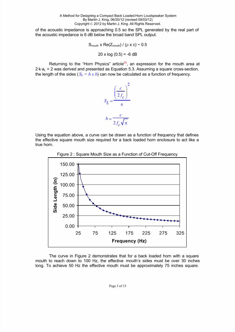
of the acoustic impedance is approaching 0.5 so the SPL generated by the real part of the acoustic impedance is 6 dB below the broad band SPL output.
Smouth x Re(Zmouth) / ( x c) ~ 0.5
20 x log (0.5) = -6 dB
Retur ning to the “Horn Physics” article(2), an expression for the mouth area at
2kaL = 2 was derived and presented as Equation 5.3. Assuming a square cross-section,
the length of the sides (S L = b x b) can now be calculated as a function of frequency.
S L
c
2 f c
2
b c2 f c
Using the equation above, a curve can be drawn as a function of frequency that definesthe effective square mouth size required for a back loaded horn enclosure to act like atrue horn.
Figure 2 : Square Mouth Size as a Function of Cut-Off Frequency
0.00
25.00
50.00
75.00
100.00
125.00
150.00
25 75 125 175 225 275 325
Frequency (Hz)
S i d e
L e n g t h ( i n
)
The curve in Figure 2 demonstrates that for a back loaded horn with a squaremouth to reach down to 100 Hz, the effective mouth’s sides must be over 30 incheslong. To achieve 50 Hz the effective mouth must be approximately 75 inches square.

7/29/2019 BLH Design Article
http://slidepdf.com/reader/full/blh-design-article 5/16
A Method for Designing a Compact Back Loaded Horn Loudspeaker SystemBy Martin J. King, 06/20/12 (revised 09/03/12)
Copyright 2012 by Martin J. King. All Rights Reserved.
Page 4 of 15
Clearly for a back loaded horn enclosure to behave as a true horn all the way down tothe lowest bass frequencies the effective mouth size must be huge.
What this means for the modest sized back loaded horn enclosures found on theInternet is that they are dominated by transmission line behavior at low frequencies andreally do not start to act like horns until they reach a frequency of a few hundred hertz.
Trying to use equations derived from classic horn theory to set flare rates, mouth areas,coupling volumes, or throat areas for a compact back loaded horn operating at lowfrequencies is really misdirected. If things work well acoustically it is by luck and not byproper application of horn physics.
Recognizing the transmission line behavior at low frequencies, and designingwith this in mind, the behavior of back loaded horn enclosures should be easier tounderstand and optimize. Then at higher frequencies, horn physics will take over and thedesign methodology should shift recognizing this change in acoustic behavior. At midrange frequencies the acoustic impedance at the throat will start to become resistive andinteract with the coupling volume to roll off the horn ’s output. Even though the TLbehavior dominates at low frequencies, I will still refer to this type of enclosure as a back
loaded horn because horn physics comes into the mix at mid range frequencies tocontrol and attenuate the mouth’s SPL output.
Influence of Room Boundaries :
Room boundaries will have two effects on the performance of a back loaded hornenclosure at low frequencies. First, sound waves emanating from the mouth reflecting off nearby boundaries return and provide additional pressure loading of the mouth changingthe acoustic impedance. The effective mouth area will appear to be larger than thephysical mouth area. Second, every room boundary cuts the volume that the horn mouthis radiating into leading to an increased sound pressure level at the listening position.This second effect is equivalent to changing the “ang” input variable in the HornResp
freeware program(3)
. These two results are important considerations during the design of compact back loaded horn enclosures.
Looking a little closer at the change in acoustic impedance at the back loadedhorn’s mouth, nearby room boundaries create reflections of the outgoing sound waves.These reflections should be thought of as emanating from phantom horn mouths on theother side of each room boundary. Each room boundary can be visualized as a mirror producing additional phantom horns equidistant behind or below the wall or floor respectively. The pressure seen at the mouth is the sum of the mouth’s self pressureloading and the pressure loading arriving from each of the nearby phantom mouths. Thecloser the horn’s mouth is to the boundary, the more significant the influence of thesereflections on the acoustic impedance. The net result will be a lowering of the frequency
at which the real part of the acoustic impedance passes through 0.5 in Figure 1; theeffective mouth will appear to be acoustically bigger than its physical dimensions.
These phantom horns, reflected on the other side of room boundaries, can alsobe visualized as additional sound sources that are summed at the listening position. Atlow frequencies where the wavelengths of sound are long, the SPL from the phantomsources will add constructively to the direct SPL from the actual speaker. However, asthe frequency rises and the wavelength of sound decreases, the SPL from the phantomsources will start to arrive out of phase with the SPL from the actual speaker producing
7/29/2019 BLH Design Article
http://slidepdf.com/reader/full/blh-design-article 6/16
A Method for Designing a Compact Back Loaded Horn Loudspeaker SystemBy Martin J. King, 06/20/12 (revised 09/03/12)
Copyright 2012 by Martin J. King. All Rights Reserved.
Page 5 of 15
severe dips. The best designs will take advantage of the sound reinforcement at lowfrequencies and roll off the mouth’s SPL output before the destructive interference startsto occur at higher frequencies.
Looking back at my previous documents addressing back loaded horn designs,the original goal was for the horn geometry to be so efficient that when its low frequency
SPL output was combined with the driver ’s SPL output the need for any form of bafflestep compensation would be eliminated. In a no compromise system(4) (5) where size isnot an issue, this approach is probably still valid. Unfortunately as nice as this conceptsounds, I no longer believe that this is possible for a reasonably sized back loaded hornenclosure design.
If at this point you buy into the transmission line analogy at lower frequencies,then placing the back loaded horn speaker out in the room will lead to the same problemof baffle step losses at low frequencies associated with sealed or ported enclosuredesigns. The expanding transmission line geometry will help produce a little more bassSPL output compared to a straight or tapered transmission line. But the key concept isusing the room boundaries to both acoustically load the back loaded horn’s mouth and
generating low frequency reflections that arrive at the listening position in phasereinforcing the bass region of the SPL frequency response.
Based on the discussion in the last few paragraphs, it should not be a bigsurprise that a back loaded horn design with the mouth on the rear baffle will probablybe preferred over a mouth located on the front baffle. A mouth on the rear baffle of aback loaded horn pushed into a room corner will maximize the mouth’s acousticimpedance boundary condition and provide an extended frequency range for theconstructive reinforcement. The low frequency performance can be adjusted bychanging the distance to the corner; smaller distances will produce larger acousticreturns.
Goals for a Back Loaded Horn Enclosure :
The primary goal of a back loaded horn enclosure is to produce a significantamount of bass output to reinforce the driver’s falling SPL response at low frequencies.Typically a back loaded horn enclosure is the first choice of DIYers with high efficiencyfull range drivers driven by low powered tube amps. A simple set of goals for a backloaded horn enclosure design are listed below.
1. Produce significant broad band bass SPL output to reinforce the driver ’sSPL output at low frequencies.
2. Roll off the SPL output from the horn’s mouth in the 100 – 300 Hz rangeeliminating destructive interference at the listening position
3. Control driver low frequency displacement, many efficient full rangedrivers have Xmax values of 1.0 mm or less.
4. If the driver displacement can be controlled / attenuated at lowfrequencies then the impedance peak associated with a driver’s resonantfrequency can be flattened.
Almost all of the back loaded horn designs I found on the Internet and analyzed indetail did not meet all of these goals. Typically the output from the mouth was peaky andstill contributing well up into the mid range frequencies. The peaky output from the

7/29/2019 BLH Design Article
http://slidepdf.com/reader/full/blh-design-article 7/16
A Method for Designing a Compact Back Loaded Horn Loudspeaker SystemBy Martin J. King, 06/20/12 (revised 09/03/12)
Copyright 2012 by Martin J. King. All Rights Reserved.
Page 6 of 15
mouth was caused by discrete standing wave resonances along the horn’s length. The
peaky output did nothing to attenuate the driver’s output resulting in constructive anddestructive interference at the listening position and dramatic swings in the system’sSPL response. Looking at the electrical impedance typically showed a series of peaks inthe magnitude plot indicative of standing wave resonances. The enclosures acted morelike undamped transmission lines which is really what they were despite the back loaded
horn label applied by the designer.
Designing a Hybrid Transmission Line / Back Loaded Horn Enclosure :
Recognizing that a back loaded horn enclosure is acting as a transmission line atlow frequencies, and does not exhibit any horn like behavior until it reaches the midrange, a design method based on transmission line acoustics can be applied. The firststep is to size the effective mouth consistent with a horn tuned between 100 and 500 Hz,this frequency range is where the mouth’s output should be rolled off. The mouth’s
physical sizing needs to take into account any of the room boundaries where there isdirect contact; for example the floor when the mouth is located at the bottom of the frontor rear baffle or even better downward firing. From Figure 2, tuning a mouth for 300 Hz
indicates a square area with 12.75 inch long sides. If the mouth is placed at the floor,this area can potentially be cut in half to achieve approximately the same tuningfrequency.
Once the mouth has been sized, the throat area and the length of the horn needto be iterated to achieve the desired fundamental tuning frequency and acoustic gain.The fundamental tuning frequency can be seen as the first peak in the acousticimpedance plot that is shown in each MathCad worksheet. Since the corner loading isgoing to reinforce the output at this frequency, the tuning of the transmission line’s firstquarter wavelength resonance can be set below the driver ’s resonant frequency.
Juggling the driver’s Qts, the expanding line’s tuning frequency, and the amount of corner loading the only way to get optimized final horn geometry is by iterating the
simulations.
Once the horn geometry has been determined, the coupling volume should besized. Equation 5.4 from the horn physics article (2) can be used to calculate the minimumcoupling volume.
This equation represents the minimum size for a coupling volume that will start to roll off the mouth’s SPL at the desired horn tuning frequency. The coupling volume can be
made larger with little impact. The bigger lever for attenuating the mouth’s output is thecoupling volume’s longest dimension and the driver position. The longest dimension anddriver position will set the quarter wave resonance between the driver and the closedend of the transmission line creating a deep null in the mouth’s SPL output. Between
tuning the coupling volume to act as a stub tube, and the coupling volume naturallyrolling off the horn’s output as frequency increases, the back loaded horn’s contributionto the system SPL response can essentially be eliminated above a selected frequency.Sizing of the mouth to establish the frequency for the onset of horn behavior, sizing thecoupling volume, and determining the internal layout of the coupling volume are
V
c S 0
2 f h
7/29/2019 BLH Design Article
http://slidepdf.com/reader/full/blh-design-article 8/16
A Method for Designing a Compact Back Loaded Horn Loudspeaker SystemBy Martin J. King, 06/20/12 (revised 09/03/12)
Copyright 2012 by Martin J. King. All Rights Reserved.
Page 7 of 15
variables that need to be optimized so everything coincides with the frequency at whichthe mouth’s SPL output is to be attenuated.
Sound simple? I have followed these basic steps many times and designed backloaded horns with expansion profiles ranging from a straight linear taper to acomplicated expansion like an exponential or hyperbolic profile. Every time the
calculated output starts to look promising, the question of how to fold the geometry andfit it into a simple box that is both compact and easy to build kills the design.
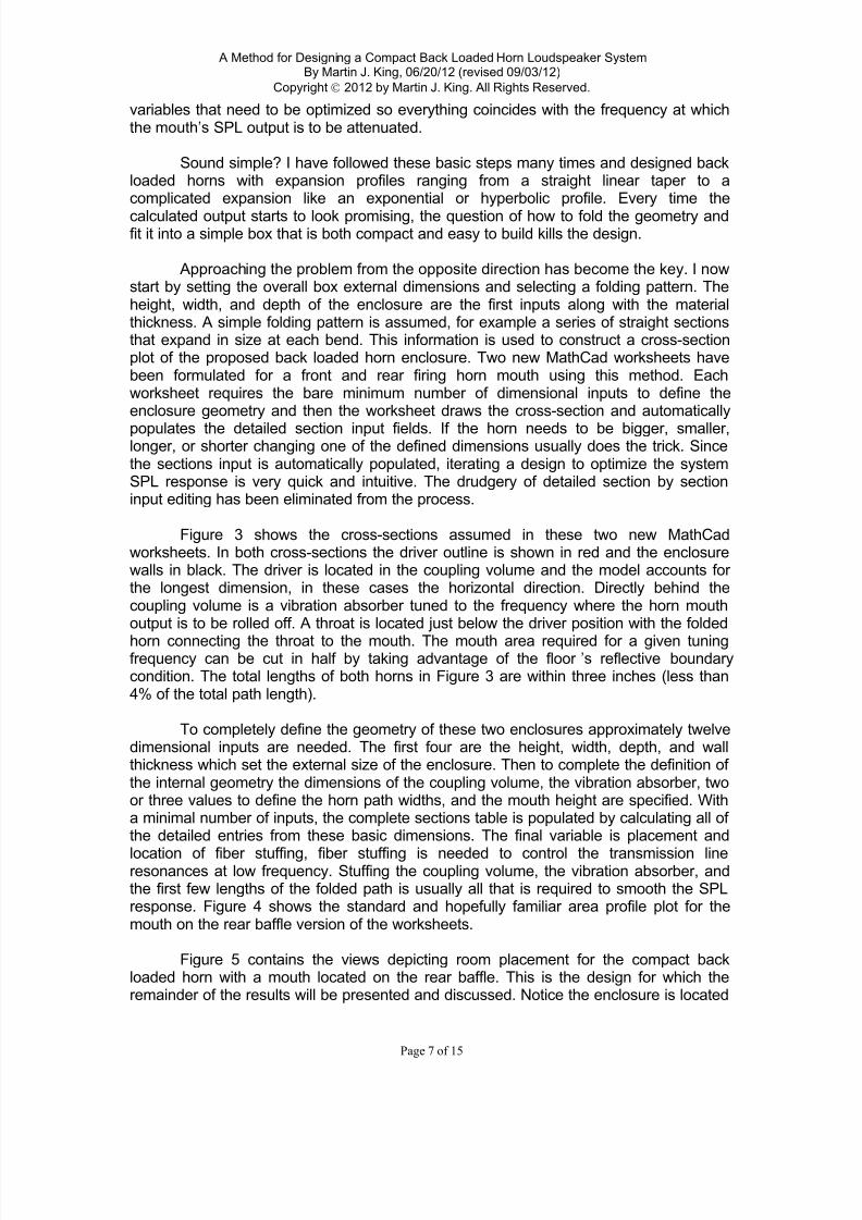
Approaching the problem from the opposite direction has become the key. I nowstart by setting the overall box external dimensions and selecting a folding pattern. Theheight, width, and depth of the enclosure are the first inputs along with the materialthickness. A simple folding pattern is assumed, for example a series of straight sectionsthat expand in size at each bend. This information is used to construct a cross-sectionplot of the proposed back loaded horn enclosure. Two new MathCad worksheets havebeen formulated for a front and rear firing horn mouth using this method. Eachworksheet requires the bare minimum number of dimensional inputs to define theenclosure geometry and then the worksheet draws the cross-section and automatically
populates the detailed section input fields. If the horn needs to be bigger, smaller,longer, or shorter changing one of the defined dimensions usually does the trick. Sincethe sections input is automatically populated, iterating a design to optimize the systemSPL response is very quick and intuitive. The drudgery of detailed section by sectioninput editing has been eliminated from the process.
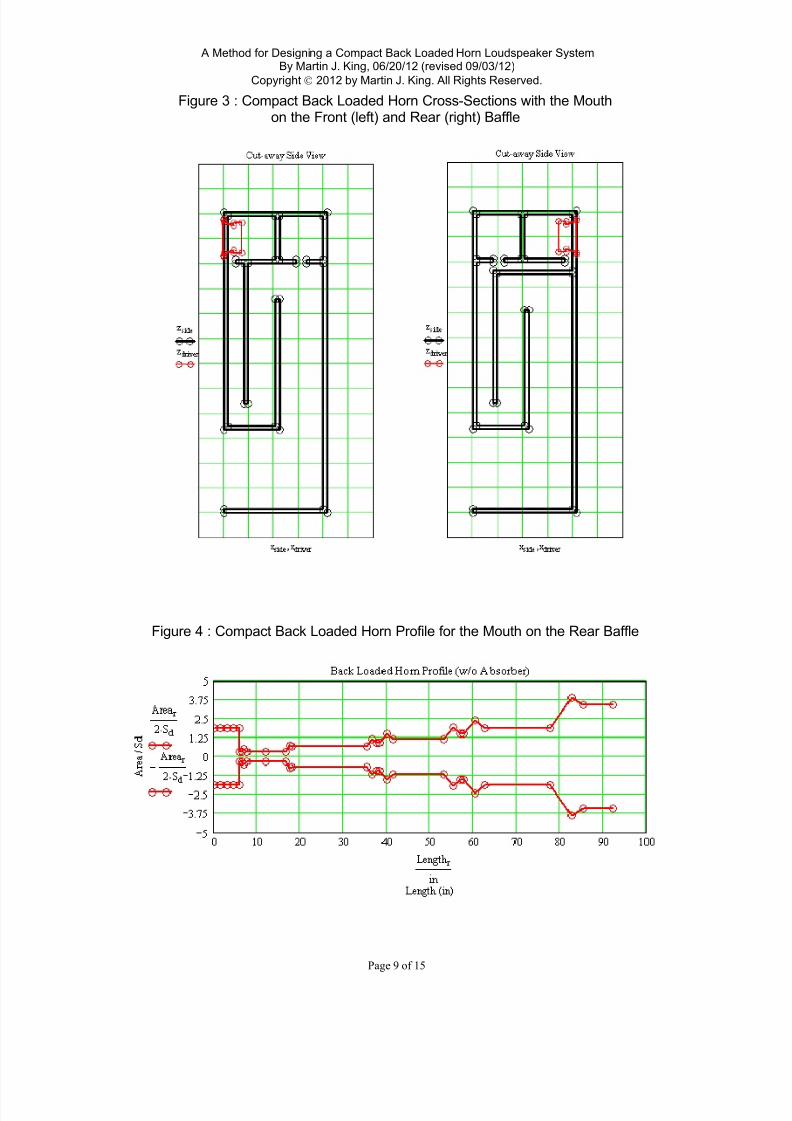
Figure 3 shows the cross-sections assumed in these two new MathCadworksheets. In both cross-sections the driver outline is shown in red and the enclosurewalls in black. The driver is located in the coupling volume and the model accounts for the longest dimension, in these cases the horizontal direction. Directly behind thecoupling volume is a vibration absorber tuned to the frequency where the horn mouthoutput is to be rolled off. A throat is located just below the driver position with the folded
horn connecting the throat to the mouth. The mouth area required for a given tuningfrequency can be cut in half by taking advantage of the floor ’s reflective boundarycondition. The total lengths of both horns in Figure 3 are within three inches (less than4% of the total path length).
To completely define the geometry of these two enclosures approximately twelvedimensional inputs are needed. The first four are the height, width, depth, and wallthickness which set the external size of the enclosure. Then to complete the definition of the internal geometry the dimensions of the coupling volume, the vibration absorber, twoor three values to define the horn path widths, and the mouth height are specified. Witha minimal number of inputs, the complete sections table is populated by calculating all of the detailed entries from these basic dimensions. The final variable is placement and
location of fiber stuffing, fiber stuffing is needed to control the transmission lineresonances at low frequency. Stuffing the coupling volume, the vibration absorber, andthe first few lengths of the folded path is usually all that is required to smooth the SPLresponse. Figure 4 shows the standard and hopefully familiar area profile plot for themouth on the rear baffle version of the worksheets.
Figure 5 contains the views depicting room placement for the compact backloaded horn with a mouth located on the rear baffle. This is the design for which theremainder of the results will be presented and discussed. Notice the enclosure is located

7/29/2019 BLH Design Article
http://slidepdf.com/reader/full/blh-design-article 9/16
A Method for Designing a Compact Back Loaded Horn Loudspeaker SystemBy Martin J. King, 06/20/12 (revised 09/03/12)
Copyright 2012 by Martin J. King. All Rights Reserved.
Page 8 of 15
very close to the room corner to take advantage of all the reflections produced by thefloor and the two walls. The responses will be calculated at a 1 meter distance, on theaxis of the driver, as shown by the small purple square in the three plots.
7/29/2019 BLH Design Article
http://slidepdf.com/reader/full/blh-design-article 10/16
A Method for Designing a Compact Back Loaded Horn Loudspeaker SystemBy Martin J. King, 06/20/12 (revised 09/03/12)
Copyright 2012 by Martin J. King. All Rights Reserved.
Page 9 of 15
Figure 3 : Compact Back Loaded Horn Cross-Sections with the Mouthon the Front (left) and Rear (right) Baffle
Figure 4 : Compact Back Loaded Horn Profile for the Mouth on the Rear Baffle

7/29/2019 BLH Design Article
http://slidepdf.com/reader/full/blh-design-article 11/16
A Method for Designing a Compact Back Loaded Horn Loudspeaker SystemBy Martin J. King, 06/20/12 (revised 09/03/12)
Copyright 2012 by Martin J. King. All Rights Reserved.
Page 10 of 15
Figure 5 : Room Corner Placement of the Compact Back loaded Horn
7/29/2019 BLH Design Article
http://slidepdf.com/reader/full/blh-design-article 12/16
A Method for Designing a Compact Back Loaded Horn Loudspeaker SystemBy Martin J. King, 06/20/12 (revised 09/03/12)
Copyright 2012 by Martin J. King. All Rights Reserved.
Page 11 of 15
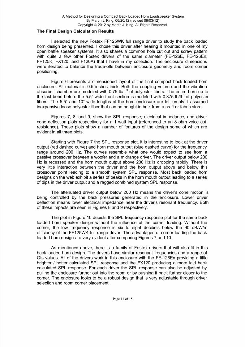
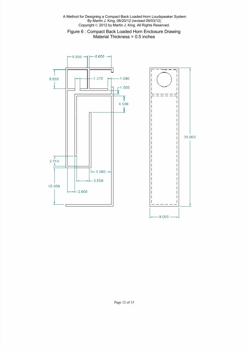
The Final Design Calculation Results :
I selected the new Fostex FF125WK full range driver to study the back loadedhorn design being presented. I chose this driver after hearing it mounted in one of myopen baffle speaker systems. It also shares a common hole cut out and screw patternwith quite a few other Fostex drivers of the same diameter (FE-126E, FE-126En,
FF125K, FX120, and F120A) that I have in my collection. The enclosure dimensionswere iterated to balance the trade-offs between enclosure geometry and room corner positioning.
Figure 6 presents a dimensioned layout of the final compact back loaded hornenclosure. All material is 0.5 inches thick. Both the coupling volume and the vibrationabsorber chamber are modeled with 0.75 lb/ft3 of polyester fibers. The entire horn up tothe last bend before the 5.5” wide front section is modeled with 0.375 lb/ft3 of polyester fibers. The 5.5” and 10” wide lengths of the horn enclosure are left empty. I assumedinexpensive loose polyester fiber that can be bought in bulk from a craft or fabric store.
Figures 7, 8, and 9, show the SPL response, electrical impedance, and driver
cone deflection plots respectively for a 1 watt input (referenced to an 8 ohm voice coilresistance). These plots show a number of features of the design some of which areevident in all three plots.
Starting with Figure 7 the SPL response plot, it is interesting to look at the driver output (red dashed curve) and horn mouth output (blue dashed curve) for the frequencyrange around 200 Hz. The curves resemble what one would expect to see from apassive crossover between a woofer and a midrange driver. The driver output below 200Hz is recessed and the horn mouth output above 200 Hz is dropping rapidly. There isvery little interaction between the driver and the horn output above and below thiscrossover point leading to a smooth system SPL response. Most back loaded horndesigns on the web exhibit a series of peaks in the horn mouth output leading to a series
of dips in the driver output and a ragged combined system SPL response.
The attenuated dr iver output below 200 Hz means the driver’s cone motion isbeing controlled by the back pressures generated in the enclosure. Lower driver deflection means lower electrical impedance near the driver’s resonant frequency. Bothof these impacts are seen in Figures 8 and 9 respectively.
The plot in Figure 10 depicts the SPL frequency response plot for the same backloaded horn speaker design without the influence of the corner loading. Without thecorner, the low frequency response is six to eight decibels below the 90 dB/W/mefficiency of the FF125WK full range driver. The advantages of corner loading the backloaded horn design are very evident after comparing Figures 7 and 10.
As mentioned above, there is a family of Fostex drivers that will also fit in thisback loaded horn design. The drivers have similar resonant frequencies and a range of Qts values. All of the drivers work in this enclosure with the FE-126En providing a littlebrighter / hotter calculated SPL response and the FX120 producing a more laid backcalculated SPL response. For each driver the SPL response can also be adjusted bypulling the enclosure further out into the room or by pushing it back further closer to thecorner. The enclosure looks to be a robust design that is very adjustable through driver selection and room corner placement.
7/29/2019 BLH Design Article
http://slidepdf.com/reader/full/blh-design-article 13/16
A Method for Designing a Compact Back Loaded Horn Loudspeaker SystemBy Martin J. King, 06/20/12 (revised 09/03/12)
Copyright 2012 by Martin J. King. All Rights Reserved.
Page 12 of 15
Figure 6 : Compact Back Loaded Horn Enclosure DrawingMaterial Thickness = 0.5 inches

7/29/2019 BLH Design Article
http://slidepdf.com/reader/full/blh-design-article 14/16
A Method for Designing a Compact Back Loaded Horn Loudspeaker SystemBy Martin J. King, 06/20/12 (revised 09/03/12)
Copyright 2012 by Martin J. King. All Rights Reserved.
Page 13 of 15
Figure 7 : SPL Response at 1 m on the Axis of the Driver
Figure 8 : Electrical Impedance Magnitude
Figure 9 : Cone Displacement

7/29/2019 BLH Design Article
http://slidepdf.com/reader/full/blh-design-article 15/16
A Method for Designing a Compact Back Loaded Horn Loudspeaker SystemBy Martin J. King, 06/20/12 (revised 09/03/12)
Copyright 2012 by Martin J. King. All Rights Reserved.
Page 14 of 15
Figure 10 : SPL Response at 1 m on the Axis of the Driver w/o the Room Corner
Conclusions :
Figure 2 pretty much tells the entire story behind back loaded horn design.Expanding geometry and mouth size determine the acoustic behavior of back loadedhorn enclosures. My contention is that almost all designs found on the Internet labeledback loaded horns are really transmission lines that transition to horn behavior at midrange frequencies. As such, designing the enclosure using horn sizing equations and notusing transmission line theory is neglecting the physics of the problem and relying moreon luck to produce an enclosure that performs as desired. Using transmission linemethods and room boundaries to reinforce the bass frequencies is one method for accurately and optimally designing this type of speaker enclosure.
Future Work :
The worksheet models shown in Figure 3 are the first two in a series of preformatted back loaded horn design worksheets. Using a limited number of geometricvariables to describe a specific design and pre populating the section input fields allowsfor quick and accurate iteration of the calculated performance. This allows the designer to rapidly focus in on an optimized geometry. The next step in the development of thesetwo models is to create an option for the path to continuously taper between the throatand the mouth. The final step will be to extend these models to simulate the symmetricdouble mouthed back loaded horns that have become very popular over the past fewyears.
The longer range goal is to create additional back loaded horn worksheets that
closely integrate with room corners so that the effective mouth area starts to approachthe requirements shown in Figure 2 for low frequency horn behavior. These worksheetswill have calculated mouth acoustic impedances that account for the boundaryreflections and push the transmission line to horn transition much lower in frequency. Iam hoping that these additional worksheets will allow bass horn performance inmoderately sized enclosures that are not too complicated to build. Quick and easysimulations that produce accurate SPL frequency responses should open up many newopportunities for high performance back loaded horn enclosure designs.

7/29/2019 BLH Design Article
http://slidepdf.com/reader/full/blh-design-article 16/16
A Method for Designing a Compact Back Loaded Horn Loudspeaker SystemBy Martin J. King, 06/20/12 (revised 09/03/12)
Copyright 2012 by Martin J. King. All Rights Reserved.
Page 15 of 15
References :
1. http://en.wikipedia.org/wiki/Horn_(acoustic)
2. http://www.quarter-wave.com/Horns/Horn_Physics.pdf
3. http://www.hornresp.net.ms/
4. http://www.passdiy.com/pdf/KleinHorn.pdf
5. http://www.passdiy.com/pdf/KleinHorn2.pdf
Related Documents