Autec Power Systems Tel:-(805)522-0888 Fax:(805)522 93 -8777 Email:[email protected] Bibliography of Terms and Introduction to Power Topologies

Welcome message from author
This document is posted to help you gain knowledge. Please leave a comment to let me know what you think about it! Share it to your friends and learn new things together.
Transcript

Autec Power Systems Tel:-(805)522-0888 Fax:(805)52293
-8777 Email:[email protected] �
Bibliography of Terms and Introduction to
Power Topologies
Autec Power Systems Tel:-(805)522-0888 Fax:(805)522-948777 Email:[email protected]
Altitude: The maximum elevation at which the converter can be used without de-rating. Ambient Temperature: The environmental temperature in which the power supply is operating, e.g., "room temperature." For forced air-cooled power supplies, the ambient temperature is considered air intake temperature. Bandwidth: The frequency band over which something is measured. Typically used in electromagnetic compatibility (EMC) testing and the measurement of output noise. Battery Backup: A power supply system that utilizes a battery to provide a source of energy for AC line failures. The battery provides input energy to maintain the DC outputs from failing. The DC source from the battery requires a special DC to DC converter. Burn In: The process of identifying power supply reliability by operating the unit at full load and rated temperature immediately after manufacture, typically for 8 hours. CFM/LFM and LFM/CFM: To convert from CFM to LFM and vice-versa, we need the cross section area of the power supply. This would be the actual area that the air is being blown through. The formula is CFM = LFM x cross sectional area. Chassis Grounding: Metal framework around converters that will normally be connected to ground internally. Some DC to DC converters have insulated cases. Chassis Mounting: Mounted to a metal or other rigid surface in the host equipment. The supply may use the chassis mount as a heat sink. Common Mode Noise: Common Mode Noise are caused by common mode current that do no circulate between AC mains and power supply. Balanced common mode currents flow simultaneously in power supply line and neutral input wires such that the common mode line current is equal in magnitude and in phase with common mode neutral current Constant Current Power Supply: A power supply delivering a constant current over a given voltage and resistive load range. The current is regulated as apposed to the voltage in a in a constant voltage power supply. Constant Voltage Power Supply: A power supply delivering a constant voltage over a given current and resistive load range. The voltage is regulated as apposed to the current in a in a constant current power supply. Control Section: In a closed-loop system, the circuitry which maintains the power supply's stability is referred to as the control section by incorporating an error amplifier to the feedback of the system.
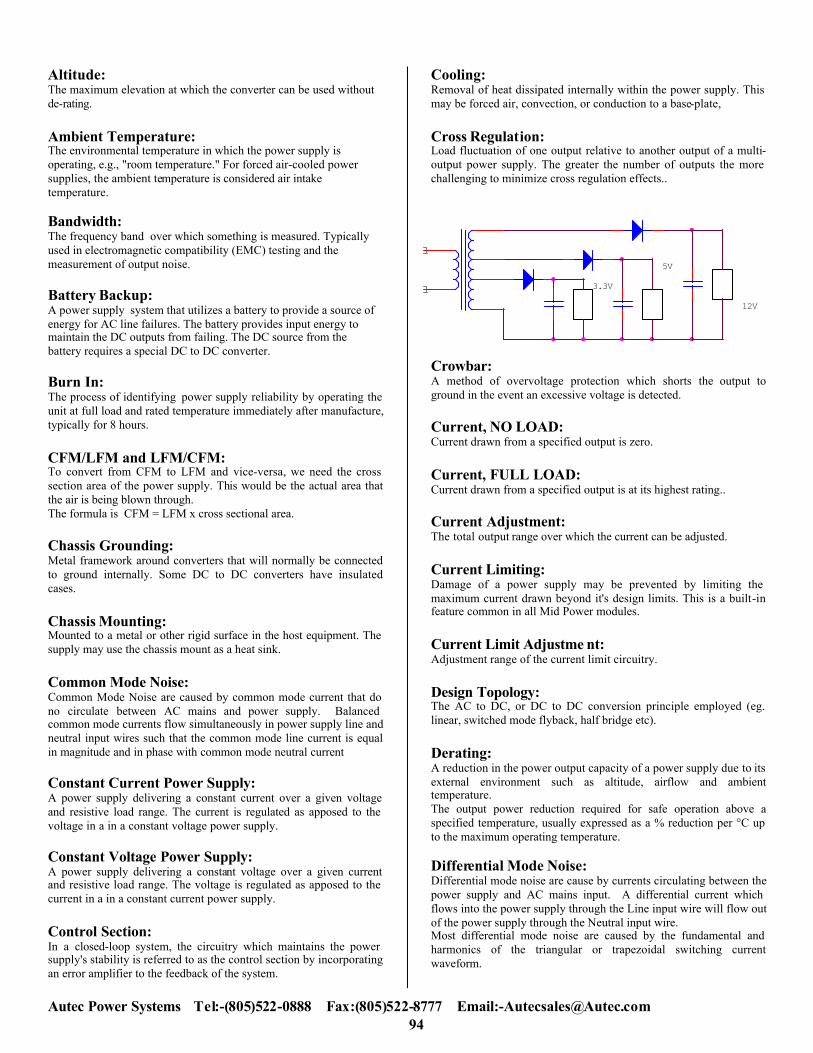
Cooling: Removal of heat dissipated internally within the power supply. This may be forced air, convection, or conduction to a base-plate, Cross Regulation: Load fluctuation of one output relative to another output of a multi-output power supply. The greater the number of outputs the more challenging to minimize cross regulation effects..
Crowbar: A method of overvoltage protection which shorts the output to ground in the event an excessive voltage is detected. Current, NO LOAD: Current drawn from a specified output is zero. Current, FULL LOAD: Current drawn from a specified output is at its highest rating.. Current Adjustment: The total output range over which the current can be adjusted. Current Limiting: Damage of a power supply may be prevented by limiting the maximum current drawn beyond it's design limits. This is a built-in feature common in all Mid Power modules. Current Limit Adjustme nt: Adjustment range of the current limit circuitry. Design Topology: The AC to DC, or DC to DC conversion principle employed (eg. linear, switched mode flyback, half bridge etc). Derating: A reduction in the power output capacity of a power supply due to its external environment such as altitude, airflow and ambient temperature. The output power reduction required for safe operation above a specified temperature, usually expressed as a % reduction per °C up to the maximum operating temperature. Differential Mode Noise: Differential mode noise are cause by currents circulating between the power supply and AC mains input. A differential current which flows into the power supply through the Line input wire will flow out of the power supply through the Neutral input wire. Most differential mode noise are caused by the fundamental and harmonics of the triangular or trapezoidal switching current waveform.
12V
5V
3.3V

Autec Power Systems Tel:-(805)522-0888 Fax:(805)522 95
-8777 Email:[email protected]
Double Insulation: Independent insulation applied to basic insulation in order to reduce the risk of electric shock in the event of a failure of the basic insulation. Drift: A change of output voltage over a period of time, independent of input, load and temperature variations. Electrostatic Discharge Precautions: Autec power supplies are built to withstand static electricity discharges. The power supplies are tested against the standard EN61000-4-2 Electrostatic discharge immunity test. All Autec power supplies can withstand up to level 4 as defined by this standard which is 8kV contact discharge and 15kV air discharge. (If power supply is of open frame construction, then it must be mounted in a suitable metal box.) Efficiency: The ratio of total output power versus true input power expressed as a percentage. Encapsulated: Totally encapsulated and hermetically sea led in cast epoxy resin or similar plastic. Enclosed: Fully enclosed power supply. Environmental Operating Temperature: The range of ambient or baseplate temperature in °C over which a power supply can be operated safely at either rated or derated output power. External Synchronization: The ability to synchronize the power supply switching frequency to an external oscillator. Input Filter: Indicates built-in line input filter to attenuate reflected ripple current. Foldback Current Limiting: The method of limiting the total output current, thus protecting the power supply, during output overload conditions. Frequency The range of AC mains frequency over which the power supply operates within specification. Ground Loop: Undesirable voltages caused by ground currents of several circuits flowing in a common ground or ground plane. Handling precautions protected: Autec power supplies are safe from electrostatic discharges and can be handled safely in normal warehouse and factory environments. The design of all Autec power supplies ensure that any electrostatic sensitive devices are fully protected once assembled into the complete power supply.
Hold-Up Time: The minimum time the power supply output(s), under full rated load, remain in regulation after loss of input power. Humidity: The maximum moisture content in the surrounding air for operation of the power supply over the specified operating temperature range. Expressed as a percentage, it is the ratio of the actual mass of water vapor present to the mass of water vapor in the same volume of saturated air at the same temperature and pressure. Impedance: The apparent impedance presented by the power supply to its output terminals. Input Voltage: The AC voltage range (in RMS root-mean-square) for which the power supply is design to operate. Inrush Current: The AC input current as measured during initial turn-on of the power supply. This current reduces to a lower steady-state current once the input capacitors charge. ISO9001: Autec manufacturing sites follow the ISO9001 Quality system which includes electrostatic handling of materials. This is defined in BS EN100015-1 1998 on taking all necessary electrostatic discharge precautions throughout the materials handling and manufacturing processes. All electrostatic precautions are audited on a regular basis to ensure consistent quality Input Common: Normally referenced to the negative side of the power supply input. Isolation: The dielectric separation between the power supply input and output, expressed as a DC test voltage, and a resistance which includes parallel capacitance. Isolation Transformer: A transformer in which the primary winding is completely isolated or separated form all secondary windings. L Bracket: Open chassis construction, chassis normally having L shaped cross section. Leakage Current: The current flowing from the input lines to the protective earth conductor when the input voltage is at nominal. Line Regulation The percentage change in output voltage caused by the input voltage varying over the specified range. Load Regulation: The percentage change in output voltage due to a change in output loading. This is usually a measurement of the output voltage deviation as the loading is changed from no load to full load.

Autec Power Systems Tel:-(805)522-0888 Fax:(805)522 96
-8777 Email:[email protected]
Logic Compatibility Type of logic signal that can be used without level change or impedance transforms. Minimum Load: The minimum amount of current which must be drawn from an output to maintain within output regulation limit. Module Load Sense: The sense termination of the power supply must be connected properly otherwise a failure can occur. When connecting sense leads, always use twisted pair cable, which minimizes line inductance and eliminates noise pickup. Twisted output power cables can eliminated noise too. Attaching a capacitor across the load is recommended to reduce noise and line inductance effects. The value of the capacitor should be carefully selected to avoid resonance, which could cause instability. Adding a low Ohm value resistor in series with the sense circuit can stabilize output voltage. Connection should be made at the power supply terminals using a precision film-type resistor. MTBF (Mean Time Between Failures): This is an indicator of reliability, and may be calculated or demonstrated. Autec calculated values are based upon Bellcore TR-332. Demonstrated values are usually arrived at by operating a population of power supplies at elevated ambient temperature at full load. MTTR: The predicted average length of time to (Mean Time To Repair) repair a faulty unit with the specified spares kit. Nominal Voltage : AC input voltage range for which the power supply is suitable for operation. OFF Control Input Voltage: Logic "lo" threshold. ON Control Input Voltage: Logic "hi" threshold. Open Frame PCB Format: Construction of a power supply is on a printed circuit board (PCB) without chassis or cover. Output Good: A TTL signal which indicates that the output voltage is within its specified regulation levels. If the output goes out of regulation, the state of this signal changes. Output Noise: The differential mode output ripple and noise as measured with a 20 MHz bandwidth. Output Power: The specified level of power of which a power supply is rated to deliver. Typically, power supplies have a continuous rating and a peak rating. These are usually a function of the ambient temperature. See "Derating."
Output Power: The rated continuous power measured in Watt. Overload Protection: A protective feature that limits output power or current demands to prevent damage to the converter. Overvoltage Protection: The use of circuitry which will protect the user's system in the event of a failure in the power supply. This circuit will limit the output voltage to a predetermined limit which, if exceeded, will cause the power supply to shut down. Overshoot: A transient change in output voltage in excess of specified regulation limits. Parallel Operation: The ability of two or more power supply outputs set to the same voltage, to be connected in parallel, to provide increased output current. Peak Current: The maximum amount of current which an output is capable of sourcing for brief periods of time. PCB Mounting: Designed for direct mounting onto printed circuit boards. Power Factor: Power factor is defined as the ratio of the actual power of an alternating current to the apparent power, or the ratio of the resistance to impedance. Power factor is calculated by determining the cosine of the phase angle between the voltage applied to a load and the current passing through the load. Power Factor Correction (PFC): Technique of increasing the power factor of a power supply. Switching power supplies without power factor correction draw current in short, high-magnitude pulses. These pulses can be smoothed out by using active or passive techniques. This reduces the input rms current and apparent input power, thereby increasing the power factor. Power factor correction is the process of installing reactive electronic components that bring the power factor of a branch or circuit closer to “unity power factor” or a power factor of 1.0. Unity power factor is obtained only when current and voltage are in phase. Loads that are inductive in nature require the installation of elements with capacitive terminal characteristics which have the primary function of improving power factor. In an application, power factor correction is accomplished by the installation of capacitors to a normally inductive circuit. As a result, power factor is increased and the total current through the circuit is closer in phase with the applied voltage. Power-factor correction is used in the design of systems that are very sensitive to unusually high currents passing through the load.

Autec Power Systems Tel:-(805)522-0888 Fax:(805)522-978777 Email:[email protected]
Power Factor (Harmonic Frequencies): Non-sinusoidal waveforms are composed of a fundamental frequency and its harmonic frequencies. Harmonics are higher frequency sine waves that are multiples of the fundamental non-sinusoidal waveform. The output of many electrical and electronic devices will be a non-sinusoidal wave when a sinusoidal input is applied. Instantaneous Power = E sin ωt x I sin(ωt+φ) Where E and I are the peak amplitudes of the voltage and current sinewaves and φ is the pahase difference between them. Hence. P=EI/2[Cosφ - cos(2ωt+φ)] The power waveform is a cosine wave at twice the frequency with an offset equal to. EI/2Cosφ = E/Sqrt2 x 1/ Sqrt2cosφ (Fig 1) To obtain power the above waveform is integrated with respect to time and since cos(2ω + φ) integrates to zero. Average power =E/Sqrt2 cosφ = Erms x Irms cosφ watts. Power Factor = real power/apparent power = watts/volts x amps = cosφ
Power Fail: A TTL signal which indicates that the input power has failed regulation limits. This signal gives the user a chance to store information or switch over to backup power before the system goes down. Power Limiting: The limiting of the total output power of a power supply. Programming: The control of power supply output voltage and/or current by varying an external parameter (voltage, current or resistance). Protection: Indicates if the power supply is fused internally. The recommended fuse rating for the power supply may be provided. Reflected Ripple: The AC current generated at the input of a AC/DC power supply or DC/DC converter by the switching action of the power switch.
Reinforced Insulation: An improved basic insulation with such mechanical and electrical properties that, in itself, the insulation provides the same degree of protection against electrical shock as double insulation. It may consist of one or more layers of insulation material. Remote Adjustment: The ability to vary output voltage and/or current over a specified range by an external control. Remote Inhibit: Power supply shutdown into a standby or idle mode by application of an external signal to the inhibit terminal. Remote Sense: The monitoring of the output voltage directly at the load rather than at the power supply output terminals; this improves regulation. Remote Sensing is accomplished by using two leads, a (+) sense lead and a (-) sense lead. The positive sense lead is connected to a positive terminal of the remote load and the negative sense lead is connected to the negative terminal of the load. Any voltage regulation measurements that are required should be made at the nodes where the remote sense leads are connected.
Remote Sensing: Remote Sensing is a power supply function that senses voltage directly at the load which takes the line drop variation out of power supply load regulation equation. The use of Remote Sensing is particularly important if the load is located away from the power supply; or if the current through the load varies erratically. Remote Sensing is also used when two or more power supplies are connected in parallel or when they are connected in redundant mode through Schottky diodes. When the voltage at the load decreases, the power supply compensates for the voltage loss ( up to 0.5V) by increasing the voltage at the supply’s output terminals. Power supplies can operate without the sense leads connected but it is recommended that sense leads are used whenever provided by the power supply manufacturer, if the load conditions, or the length of the output cables dictate that voltage drops will occur at the load. Resolution: The smallest incremental step adjustment possible by use of built-in controls. Reverse Voltage Protection: A built-in circuit (or element) that protects the power supply from damage when a reverse polarity applied across the input terminals,
E
I
Power
Average Power=1/2EI cos ff
ff
Voltage, Current and power curves in a single phase AC circuit
Average power = ½ EI, cosφ.
+
-

Autec Power Systems Tel:-(805)522-0888 Fax:(805)522 98
-8777 Email:[email protected]
RFI Standards: Limits laid down by various national and international regulatory agencies for radio frequency interference generated by electrical and electronic equipment Ripple and Noise: The sum of the switching ripple and all the voltage noise components expressed as a peak to peak amplitude over a specified bandwidth. The differential mode measurement is taken over a 20 MHz bandwidth. Safety Approved: Approval, listing or certification of the power supply has been obtained for the standards specified. Safety Circuit: Any circuit (either the primary or the secondary) that is relied upon to reduce risks of electrical shock or fire (an interlock circuit, for example). Safety Isolation: The electrical separation between the primary and secondary circuits and the safety standards to which the power supply conforms in this respect. Safety Standards: Standards laid down by various national and international regulatory agencies. Secondary Circuits: Secondary circuits are those circuits supplied from transformer output windings that are electrically separated from the primary windings. Series Operation: The ability of two or more power supply outputs to be wired in series to provide a higher output voltage. Setting Accuracy: The percentage difference between the actual voltage setting and the nominal output voltage at rated load and nominal line input voltage. Shock Standards: Definition of the mechanical "bump" tests that can be applied to the power supply without damage. Short Circuit Protection: In the event that the output is shorted, this circuit will protect the power supply by limiting the amount of current flowing through the short circuit. Shutdown Idle Current: Current drawn by the power supply during standby mode. Storage Temperature: The range of ambient temperatures over which a power supply may be stored long term without damage. Temperature expressed in °C. Switching Frequency: The switching speed of the power supply power switch.
Switching Spike: The peak to peak amplitude of the voltage spike which occurs at switching frequency on the output of switched mode power supply. Temperature Coefficient: The effect of ambient temperature changes upon output voltage regulation, expressed as a percentage change per degree of temperature. Temperature Derating: The reduction in output power due to an increase in ambient temperature. Temperature Range: Operating: The specified ambient temperature over which it is safe to operate the power supply. Storage: The specified ambient temperature in which the power supply can be stored without risk of damage. Thermal Protection: An internal temperature trip that shuts down the power supply if the internal temperature exceeds a predetermined limit. Transient Response: The maximum time for the output voltage to return within regulation limits following a specific load step change. Turn-ON Delay: The time in seconds for the output(s) to reach their nominal voltage(s) within regulation limits after the input is being switched on. Ventilated Case: Enclosed in a metal case with ventilation slots for cooling by convection or forced air. Vibration Standards: Definition of the amplitude and frequency of mechanical vibration that can be applied to the power supply without damage. Voltage Adjustment: The range over which the output voltage can be adjusted (and the means of adjustment). Voltage Balance: The difference, expressed as a percentage between the voltage magnitudes of a twin output power supply, where the outputs have the same nominal voltage but the opposite polarity. Voltage Range : The range of input voltage over which the power supply operates.
Autec Power Systems Tel:-(805)522-0888 Fax:(805)522 99
-8777 Email:[email protected]
The EMC Directive The EMC Directive, 89/336/EEC, requires that end user equipment meets prescribed electromagnetic compatibility requirements. In the majority of cases, conformity to the EMC directive can be demonstrated by compliance with EN50081 for emissions and EN50082 for susceptibility. These are known as the “Generic EMC
The EN50081 emissions standard includes reference to EN60555-2 which relates to household appliances and limits the harmonics of line current which may be drawn from the mains supply. This means that household appliances need to meet the limits of EN60555-2 in order to demonstrate conformity with the EMC directive. However, professional and industrial equipment is not currently within the scope of EN60555-2. A related standard, EN61000-3-2, has been published in the Official Journal of the European Commission and is, therefore, available for reference. This standard includes limits for line current harmonics for all equipment with input current up to and including 16A. However, it is not referred to from EN50081 and, therefore, is not a mandatory requirement in order to demonstrate conformity with the EMC directive. The exception to this is in the case where a product specific standard exists which does refer to EN61000-3-2. In this circumstance, the product specific standard takes precedence over the generic standard and equipment within the scope of that standard will need to meet the requirements of EN61000-3-2. This is the position at the date of publication of this note. However, a date of withdrawal of EN60555-2 has been set at 1/1/2001 beyond which a replacement standard will need to be incorporated in the generic standards. EN61000-3-2 has been cited as the intended replacement for EN60555-2. The impact of this will be that all end user electrical and electronic apparatus will need to meet the requirements of EN61000-3-2 from 1/1/2001. This situation is explained in CENELEC communication, CLC(SG)637 published in July, 1997. (This communication also discusses the withdrawal of Amendment A12 to EN61000-3-2 in which an implementation date of June 1998 had previously been proposed.) Safety Approval of North American Products UL/CSA Bi-National Standard Traditionally, for comprehensive commercial coverage of the North American market, manufacturers of electrical and electronic equipment were required to submit their products to both the Canadian and US safety agencies. This inevitably would create a long and expensive approval process, as both agencies would require product samples and supporting documentation for approval to the IEC950 family of standards. The alternative rout is, the BI-national standard. This is a joint publication from UL and CSA that became effective during 1995. It is a combination of UL1950 and CSA 22.2 No. 950 safety standards, both of which are based on the IEC950 safety publication. In general, any products tested and approved to the BI-national standard by either CSA or UL meet all the applicable requirements for safety of that product type in both Canada and the US. The main advantages of this method are reduced cost and time as only one agency is now involved, resulting in a more efficient and timely approval process. Products tested and approved to the BI-national standard by CSA carry the NRTL/C mark and carry full regulatory acceptance in Canada and the US. Products tested and approved by UL carry the UL/c mark and also have full regulatory acceptance in Canada and the US. This means any Autec power supply bearing either the CUS marking can simply be incorporated within a users system, regardless of which North American agency the system is submitted to, for final approval. During this system approval the power supply should only
be evaluated to see if it is operating within its limits, as specified in the BI-National safety test report. EMC(Electromagnetic Compatibility): The requirement for electromagnetic emissions and susceptibility dictated by the physical environment and regulatory governing bodies in whose jurisdiction a piece of equipment is operated EMI (Electromagnetic Interference): Signals emanating from internal or external sources that disrupt or prevent operation of electronic systems. In present practice, the term "EMI" (which refers to the emission of unwanted signals), has been replaced by "EMC" (which refers to both emissions and susceptibility). IEC 601 (EN60601): The safety standard specified by the International Electrotechnical Commission, which cover electrical medical and dental equipment that is intended for professional use. Although this specification's primary focus is on safety, there are some requirements regarding reliable operation.

Autec Power Systems Tel:-(805)522-0888 Fax:(805)522 100
-8777 Email:[email protected]
Power Supply Topologies
1. Linear Power Supplies
2. Switch-Mode Power Supplies a. Flyback Converter (Buck-Boost) b. Forward Converter (Buck regulator) c. Boost-Buck or Æuk Converter d. Push-Pull Converter e. Half-Bridge Converter f. Full-Bridge Converter
3. Control Techniques
a. Current Mode PWM b. Resonant Mode
Switch Mode Power Supplies Switching power supplies regulate by varying the duty cycle of a transistor on the primary side of the transformer in a fast switching technique. This produces high efficiency and reliability with minimum heat generation. The control technique is known as Pulse Width Modulation (PWM) and typically ranges from 40kHz to 150kHz. The pulse width is longer at lower input voltages and shorter at higher input voltages. Flyback Converter (Buck-Boost) The Flyback Converter has become very popular for power requirements below about 150 Watts because of its circuit simplicity and low cost. The flyback converter is functionally identical to a buck-boost converter. It is known as flyback converter because the diode turn-on occurs when the inductor output coil voltage “flies back” as the input switch turns off. Fig. 1 shows the fundamental principles of flyback conversion. When T1 conducts, current rises linearly in the primary of the transformer. The transformer is designed to have a high inductance so that energy is stored as the flux
builds up. Winding polarity ensures that diode D1 is reverse biased during this period so no transformer secondary current flows. When T1 turns off, flux in the transformer decays
generating a secondary current which flows to the load and charges capacitor Co. Energy is stored in the transformer field during the "on" period of the switch T1 and transferred to the load during the "off" (flyback) period. Capacitor Co is a reservoir maintaining voltage across the load during the "on" period. Comparing the output voltage with a reference voltage and using the difference to vary the “on” time of T1 achieves regulation of the secondary voltage. Energy transfer to the secondary is therefore controlled to maintain secondary voltage independently of load and supply voltage changes. Varying the "on" time of T1 may be carried out by pulse width modulation (PWM) driven at a constant frequency by a local oscillator, or, in the simplest and lowest cost schemes, by self-oscillation. In this case as the load changes, the frequency varies to vary the "on" time
Forward Converter (Buck Regulator)
The forward converter is cost effective from 100 to 250 watts. As Fig. 2 shows, it is more complex than the basic flyback circuit, but its operation is still fairly simple. When switching transistor Q1 is turned "on", current builds up in the primary and secondary windings simultaneously. Because winding polarity forward biases D1, secondary current flows via L to the load and flux builds up in L creating an energy store. Q1 turns "off", primary current collapses reversing the secondary voltage. D1 is now reversed biased blocking current flow in the transformer secondary, but D2, the "flywheel" diode, now conducts allowing L to discharge into the load. Unlike the flyback converter current flows from the energy storage inductor to the load during on and off times of the switch Q1 resulting in half the peak currents in the secondary diodes and inherently lower output ripple.
Boost-Buck (Æuk Converter) Like the buck-boost, the boost-buck exhibits a polarity reversal between the input and output. The center capacitor serves as a transfer voltage source. It takes energy from the input side, stores it briefly, and then sends it on to the load. This arrangement is also known as a Æuk Converter, named after the developer who patented it in the mid-1970s.
Ci
D1
Lr
T1
Ui UoCo
Figure One – Buck-Boost Converter
Ci
D1
Vi
VoCo
D2
D3
L
Q1
Figure Two – Forward Converter
Autec Power Systems Tel:-(805)522-0888 Fax:(805)522 101
-8777 Email:[email protected]
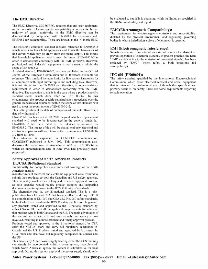
Push Pull Converter To make more efficient use of the magnetic cores, push pull converters have been developed. Essentially, the push pull converter consists of two forward converters driven by anti-phase inputs. The two diodes D1 and D2 in the secondary act as both forward and flywheel diodes. Ideally conduction times of Q1 and Q2 are equal, the transformer is driven symmetrically, and unlike the single ended converters, because there is no DC component in the drive, no air gap is necessary in the magnetic path. This results in approximately half the core volume for the same power. A major difficulty arises with this circuit because the transformer saturates if the characteristics of the switching transistors are not precisely matched. Core saturation results in rapid thermal runaway and destruction of one of the transistors. Solutions to this problem are complex and expensive. So for higher power (200 watt plus) applications, half bridge and full bridge converters have been developed.
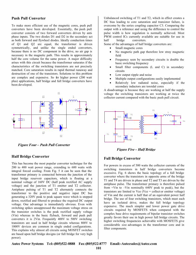
Half Bridge Converter This has become the most popular converter technique for the 200 to 400 watt power range, extending to 600 watts with integral forced cooling. From Fig. 5 it can be seen that the transformer primary is connected between the junction of the input bridge reservoir capacitors, which is floating at a nominal voltage of 160V DC (half peak rectified AC supply voltage) and the junction of T1 emitter and T2 collector. Antiphase pulsing of T1 and T2 alternately connects the transformer to the positive and negative input DC bus generating a 320V peak to peak square wave which is stepped down, rectified and filtered to produce the required DC output voltage. One advantage is immediately obvious. Even with switching spikes unsuppressed the maximum voltage stress on the transistor switches is the peak rectified supply voltage (Vin) whereas in the basic flyback, forward and push pull converters it is 2Vin. Frequently 400V to 500V switching transistors are used in half bridge circuits whereas 800V to 1000V devices are common in single ended configurations. This explains why almost all circuits using MOSFET switches are based upon half bridge designs (or full bridge for very high power).
Unbalanced switching of T1 and T2, which in effect creates a DC bias leading to core saturation and transistor failure, is overcome by the series coupling capacitor C3. Comparing the output with a reference and using the difference to control the pulse width is how regulation is normally achieved. Most PWM control ICs currently available are suitable for use in half bridge converters. Some of the advantages of half bridge converters are:
• Small magnetic cores • No magnetic path gap therefore low stray magnetic
field • Frequency seen by secondary circuits is double the
basic switching frequency • Small filter components (L and C) in secondary
circuits • Low output ripple and noise • Multiple output configurations easily implemented • Relatively low radiated noise, especially if the
secondary inductors are toroidal cores A disadvantage is because they are working at half the supply voltage the switching transistors are working at twice the collector current compared with the basic push pull circuit.
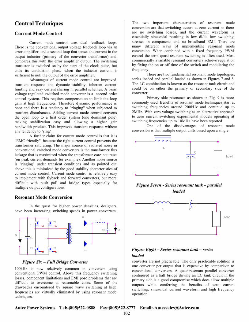
Full Bridge Converter For powers in excess of 500 watts the collector currents of the switching transistors in half bridge converters become excessive. Fig. 6 shows the basic topology of a full bridge converter where the transistors in opposite arms of the bridge T1 and T4 are driven in phase and T2 and T3 are driven by the antiphase pulse. The transformer primary is therefore pulsed from +Vin to -Vin nominally 640V peak to peak), but the transistors are limited to Vce (Vce = collect or emitter voltage) of Vin and the current is half that of an equivalent power half bridge. The use of four switching transistors, which must each have an isolated drive, makes the full bridge topology expensive. The much simpler and lower power gate drive circuits required by MOSFETS when compared with the complex base drive requirements of bipolar transistor switches greatly favors their use in high power full bridge circuits. The higher switching frequencies achievable with MOSFETS give considerable size advantages in the transformer core and in filter components.
Vi Ci
Co Vo
D1
D2
LQ1
Q2
Figure Four – Push Pull Converter
Vi
Ci1
Co Vo
D1
D2
L T1
T2Ci2
Figure Five – Half Bridge
Autec Power Systems Tel:-(805)522-0888 Fax:(805)522 102
-8777 Email:[email protected]
D1
T2
Vi
L
D2
Co Vo
T1
T4 T3
Ci
Figure Six – Full Bridge Converter
LC
Load
Figure Seven - Series resonant tank – parallel loaded
L C
Load
Figure Eight – Series resonant tank – series loaded
Control Techniques Current Mode Control
Current mode control uses dual feedback loops. There is the conventional output voltage feedback loop via an error amplifier, and a second loop that senses the current in the output inductor (primary of the converter transformer) and compares this with the error amplifier output. The switching transistor is switched on by the start of the clock pulse, but ends its conduction phase when the inductor current is sufficient to null the output of the error amplifier.
Advantages of current mode control are improved transient response and dynamic stability, inherent current limiting and easy current sharing in parallel schemes. A basic voltage regulated switched mode converter is a second order control system. This requires compensation to limit the loop gain at high frequencies. Therefore dynamic performance is poor and there is a tendency to "ringing" when subjected to transient disturbances. Adding current mode control converts the open loop to a first order system (one dominant pole) making stabilization easy and allowing a higher gain bandwidth product. This improves transient response without any tendency to "ring".
A further claim for current mode control is that it is "EMC friendly", because the tight current control prevents the transformer saturating. The major source of radiated noise in conventional switched mode converters is the transformer flux leakage that is maximized when the transformer core saturates (on peak current demands for example). Another noise source is "ringing" under transient conditions and as pointed out above this is minimized by the good stability characteristics of current mode control. Current mode control is relatively easy to implement with flyback and forward converters, but more difficult with push pull and bridge types especially for multiple output configurations. Resonant Mode Conversion
In the quest for higher power densities, designers have been increasing switching speeds in power converters.
100kHz is now relatively common in converters using conventional PWM control. Above this frequency switching losses, component limitations and EMI pose problems that are difficult to overcome at reasonable costs. Some of the drawbacks encountered by square wave switching at high frequencies are virtually eliminated by using resonant mode techniques.
The two important characteristics of resonant mode conversion are that switching occurs at zero current so there are no switching losses, and the current waveform is essentially sinusoidal resulting in low dI/dt, low switching stresses in components and no broadband EMI. There are many different ways of implementing resonant mode conversion. When combined with a fixed frequency PWM control the term quasi-resonant switching is often used. Most commercially available resonant converters achieve regulation by fixing the on or off time of the switch and modulating the frequency.
There are two fundamental resonant mode topologies, series loaded and parallel loaded as shown in Figures 7 and 8. The LC combination is known as the resonant tank circuit and could be on either the primary or secondary side of the converter.
Primary side resonance as shown in Fig. 9 is more commonly used. Benefits of resonant mode techniques start at switching frequencies around 200kHz and continue up to 2MHz. With zero voltage switching as an alternative approach to zero current switching experimental models operating at switching frequencies up to 10MHz have been reported.
One of the disadvantages of resonant mode conversion is that multiple output units based upon a single
converter are not practicable. The only practicable solution is one converter per output that is expensive by comparison to conventional converters. A quasi-resonant parallel converter configured as a half bridge driving an LC tank circuit in the primary side is a good compromise which does allow multiple outputs while conferring the benefits of zero current switching, sinusoidal current waveform and high frequency operation.
Related Documents


![[] Topologies for Uninterruptible Power Supplies[1993]{Krishnan}](https://static.cupdf.com/doc/110x72/577cc6881a28aba7119e8654/-topologies-for-uninterruptible-power-supplies1993krishnan.jpg)
