1 BELT TECHNICAL HANDBOOK 2012.1

Welcome message from author
This document is posted to help you gain knowledge. Please leave a comment to let me know what you think about it! Share it to your friends and learn new things together.
Transcript
1 BELT TECHNICAL HANDBOOK 2012.1
2 BELT TECHNICAL HANDBOOK 2012.1
BELT CONVEYOR STRAIGHT, CURVE AND INCLINED TECH HANDBOOK
TABLE OF CONTENTS
TABLE OF CONTENTS .................................................................................................................................. 2, 3
GENERAL SAFETY STATEMENTS .................................................................................................................. 4
-Introduction ..................................................................................................................................................... 4
-Cautions, Warnings and Hazards ..................................................................................................................... 4
SAFETY INFORMATION ............................................................................................................................... 5
-Safety Labels .................................................................................................................................................... 5, 6
-Installation Safety ............................................................................................................................................ 7
-Electrical Safety ................................................................................................................................................ 8
-Operational Safety ........................................................................................................................................... 9
-Maintenance and Service Safety...................................................................................................................... 10, 11
-Belt Safety Instructions .................................................................................................................................... 12
RECEIVING AND INSPECTION ...................................................................................................................... 13
-Returns, Damages and Shortages ................................................................................................................... 13
-Removal of Crating .......................................................................................................................................... 13
GENERAL INSTALLATION ............................................................................................................................ 14
-Understanding Pop-Out Rollers ....................................................................................................................... 14
-Belt Lacing ........................................................................................................................................................ 14
-Checking Unit Squareness ................................................................................................................................ 15
-Squaring ........................................................................................................................................................... 15
-Coupling / Attaching Bed Sections ................................................................................................................... 16
LEG SUPPORTS AND INSTALLATION............................................................................................................ 17
-Permanent Installation of Legs ........................................................................................................................ 17-19
-Leg Adjustments .............................................................................................................................................. 17-19
KNEE BRACES, CASTERS AND CEILING HANGERS ........................................................................................ 20
-Installing Knee Braces and Casters .................................................................................................................. 20, 21
-Installing Ceiling Hangers ................................................................................................................................. 22
MULTI-TIER SUPPORTS ............................................................................................................................... 23
-Installation of Multi-Tier Supports ................................................................................................................... 23
ASSEMBLY .................................................................................................................................................. 24
-Straight Belt Conveyor Installation Instructions .............................................................................................. 24, 25
-Inclined Belt Conveyor Installation Instructions .............................................................................................. 26-28
INSTRUCTIONS FOR BELT TRACKING .......................................................................................................... 29
-Belt Type 1 ....................................................................................................................................................... 29
-Belt Type 2 ....................................................................................................................................................... 30
-Belt Type 3 ....................................................................................................................................................... 31
-Belt Type 4 ....................................................................................................................................................... 32, 33
-Belt Type 5 ....................................................................................................................................................... 34, 35
- Belt Curve Tensioning ..................................................................................................................................... 36
PRE-START-UP OVERVIEW .......................................................................................................................... 37
-Preparing for Initial Start-Up ........................................................................................................................... 37
-Drive Chain and Sprocket Alignment ............................................................................................................... 38
-Drive Chain and Sprocket Tension ................................................................................................................... 39
-Gear Reducer Vent Plug ................................................................................................................................... 39

3 BELT TECHNICAL HANDBOOK 2012.1
BELT CONVEYOR STRAIGHT, CURVE AND INCLINED TECH HANDBOOK
TABLE OF CONTENTS (Continued)
MAINTENANCE ........................................................................................................................................... 40
-Inspection and Lubrication .............................................................................................................................. 40
-Maintenance Schedules ................................................................................................................................... 41
-Report on Miscellaneous Maintenance Performed ......................................................................................... 42
TROUBLESHOOTING AND REPLACEMENT PARTS ........................................................................................ 43
-Troubleshooting ............................................................................................................................................... 43
PARTS LISTS ................................................................................................................................................ 44
-Belt Straight Roller Bed .................................................................................................................................... 44
-Belt Straight Slider Bed .................................................................................................................................... 45
-Belt Curve......................................................................................................................................................... 46
-Incline Belt Style 1 ............................................................................................................................................ 47
-Incline Belt Style 2 ............................................................................................................................................ 48
-Decline Belt Style 3 .......................................................................................................................................... 48
NOTES ........................................................................................................................................................ 49
WARRANTY ................................................................................................................................................ 50
4 BELT TECHNICAL HANDBOOK 2012.1
BELT CONVEYOR STRAIGHT, CURVE AND INCLINED TECH HANDBOOK
GENERAL SAFETY STATEMENTS
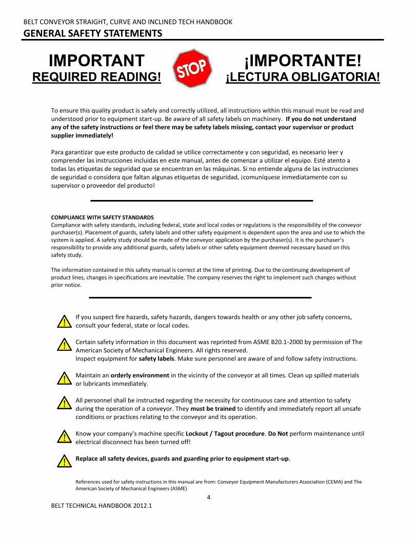
To ensure this quality product is safely and correctly utilized, all instructions within this manual must be read and understood prior to equipment start-up. Be aware of all safety labels on machinery. If you do not understand any of the safety instructions or feel there may be safety labels missing, contact your supervisor or product supplier immediately! Para garantizar que este producto de calidad se utilice correctamente y con seguridad, es necesario leer y comprender las instrucciones incluidas en este manual, antes de comenzar a utilizar el equipo. Esté atento a todas las etiquetas de seguridad que se encuentran en las máquinas. Si no entiende alguna de las instrucciones de seguridad o considera que faltan algunas etiquetas de seguridad, ¡comuníquese inmediatamente con su supervisor o proveedor del producto!
COMPLIANCE WITH SAFETY STANDARDS Compliance with safety standards, including federal, state and local codes or regulations is the responsibility of the conveyor purchaser(s). Placement of guards, safety labels and other safety equipment is dependent upon the area and use to which the system is applied. A safety study should be made of the conveyor application by the purchaser(s). It is the purchaser’s responsibility to provide any additional guards, safety labels or other safety equipment deemed necessary based on this safety study. The information contained in this safety manual is correct at the time of printing. Due to the continuing development of product lines, changes in specifications are inevitable. The company reserves the right to implement such changes without prior notice.
If you suspect fire hazards, safety hazards, dangers towards health or any other job safety concerns, consult your federal, state or local codes. Certain safety information in this document was reprinted from ASME B20.1-2000 by permission of The American Society of Mechanical Engineers. All rights reserved. Inspect equipment for safety labels. Make sure personnel are aware of and follow safety instructions. Maintain an orderly environment in the vicinity of the conveyor at all times. Clean up spilled materials or lubricants immediately. All personnel shall be instructed regarding the necessity for continuous care and attention to safety during the operation of a conveyor. They must be trained to identify and immediately report all unsafe conditions or practices relating to the conveyor and its operation. Know your company’s machine specific Lockout / Tagout procedure. Do Not perform maintenance until electrical disconnect has been turned off! Replace all safety devices, guards and guarding prior to equipment start-up.
References used for safety instructions in this manual are from: Conveyor Equipment Manufacturers Association (CEMA) and The American Society of Mechanical Engineers (ASME)
IMPORTANT REQUIRED READING!
¡IMPORTANTE! ¡LECTURA OBLIGATORIA!
5 BELT TECHNICAL HANDBOOK 2012.1
BELT CONVEYOR STRAIGHT, CURVE AND INCLINED TECH HANDBOOK
SAFETY INFORMATION: SAFETY LABELS
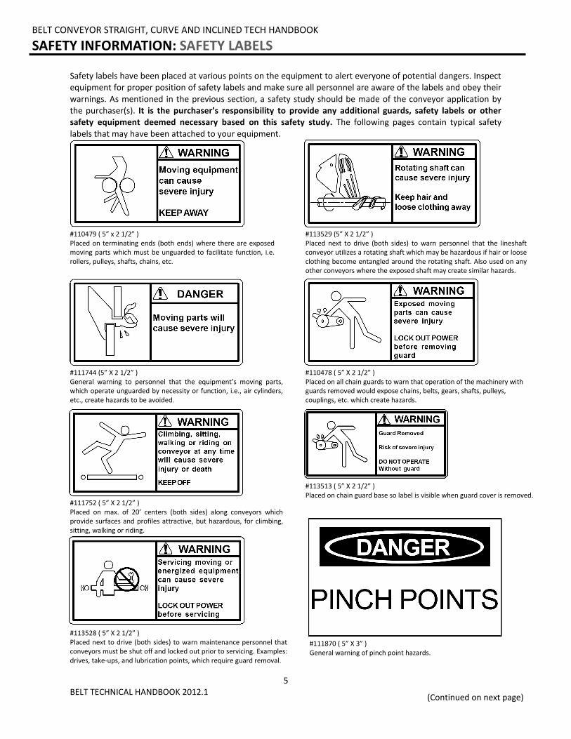
Safety labels have been placed at various points on the equipment to alert everyone of potential dangers. Inspect equipment for proper position of safety labels and make sure all personnel are aware of the labels and obey their
warnings. As mentioned in the previous section, a safety study should be made of the conveyor application by the purchaser(s). It is the purchaser’s responsibility to provide any additional guards, safety labels or other safety equipment deemed necessary based on this safety study. The following pages contain typical safety
labels that may have been attached to your equipment.
#110479 ( 5” x 2 1/2” ) Placed on terminating ends (both ends) where there are exposed moving parts which must be unguarded to facilitate function, i.e. rollers, pulleys, shafts, chains, etc.
#113529 (5” X 2 1/2” ) Placed next to drive (both sides) to warn personnel that the lineshaft conveyor utilizes a rotating shaft which may be hazardous if hair or loose clothing become entangled around the rotating shaft. Also used on any other conveyors where the exposed shaft may create similar hazards.
#111744 (5” X 2 1/2” ) General warning to personnel that the equipment’s moving parts, which operate unguarded by necessity or function, i.e., air cylinders, etc., create hazards to be avoided.
#110478 ( 5” X 2 1/2” ) Placed on all chain guards to warn that operation of the machinery with guards removed would expose chains, belts, gears, shafts, pulleys, couplings, etc. which create hazards.
#111752 ( 5” X 2 1/2” ) Placed on max. of 20’ centers (both sides) along conveyors which provide surfaces and profiles attractive, but hazardous, for climbing, sitting, walking or riding.
#113513 ( 5” X 2 1/2” ) Placed on chain guard base so label is visible when guard cover is removed.
#113528 ( 5” X 2 1/2” ) Placed next to drive (both sides) to warn maintenance personnel that conveyors must be shut off and locked out prior to servicing. Examples: drives, take-ups, and lubrication points, which require guard removal.
#111870 ( 5” X 3” ) General warning of pinch point hazards.
(Continued on next page)

6 BELT TECHNICAL HANDBOOK 2012.1
BELT CONVEYOR STRAIGHT, CURVE AND INCLINED TECH HANDBOOK
SAFETY INFORMATION: SAFETY LABELS (Continued)
#111750 ( 1 3/4” x 1 1/4” ) Generally placed on smaller guards to alert personnel of potential danger if guard is removed and power is not locked out.
#111749 ( 3” x 1 1/4” ) Placed on shipping brace which stabilizes equipment during shipping. Brace must be removed before operating! May cause severe injury if not removed.
#110491 (10” x 7” ) Placed on equipment where conveyors may start without warning.
7 BELT TECHNICAL HANDBOOK 2012.1
1) LOADING / UNLOADING Have trained personnel load or unload equipment. The conveyor must be properly handled when transferring from the unloading area to final site location to prevent damage.
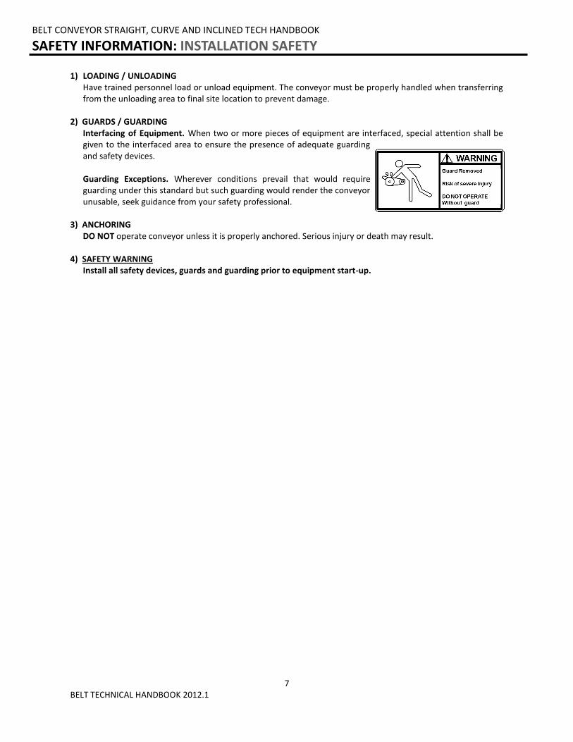
2) GUARDS / GUARDING Interfacing of Equipment. When two or more pieces of equipment are interfaced, special attention shall be
given to the interfaced area to ensure the presence of adequate guarding and safety devices.
Guarding Exceptions. Wherever conditions prevail that would require
guarding under this standard but such guarding would render the conveyor unusable, seek guidance from your safety professional.
3) ANCHORING DO NOT operate conveyor unless it is properly anchored. Serious injury or death may result. 4) SAFETY WARNING Install all safety devices, guards and guarding prior to equipment start-up.
BELT CONVEYOR STRAIGHT, CURVE AND INCLINED TECH HANDBOOK
SAFETY INFORMATION: INSTALLATION SAFETY
8 BELT TECHNICAL HANDBOOK 2012.1
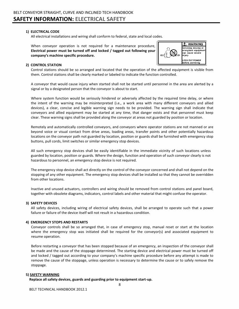
1) ELECTRICAL CODE All electrical installations and wiring shall conform to federal, state and local codes. When conveyor operation is not required for a maintenance procedure,
Electrical power must be turned off and locked / tagged out following your company’s machine specific procedure.
2) CONTROL STATION
Control stations should be so arranged and located that the operation of the affected equipment is visible from them. Control stations shall be clearly marked or labeled to indicate the function controlled. A conveyor that would cause injury when started shall not be started until personnel in the area are alerted by a signal or by a designated person that the conveyor is about to start. Where system function would be seriously hindered or adversely affected by the required time delay, or where the intent of the warning may be misinterpreted (i.e., a work area with many different conveyors and allied devices), a clear, concise and legible warning sign needs to be provided. The warning sign shall indicate that conveyors and allied equipment may be started at any time, that danger exists and that personnel must keep clear. These warning signs shall be provided along the conveyor at areas not guarded by position or location. Remotely and automatically controlled conveyors, and conveyors where operator stations are not manned or are beyond voice or visual contact from drive areas, loading areas, transfer points and other potentially hazardous locations on the conveyor path not guarded by location, position or guards shall be furnished with emergency stop buttons, pull cords, limit switches or similar emergency stop devices. All such emergency stop devices shall be easily identifiable in the immediate vicinity of such locations unless guarded by location, position or guards. Where the design, function and operation of such conveyor clearly is not hazardous to personnel, an emergency stop device is not required. The emergency stop device shall act directly on the control of the conveyor concerned and shall not depend on the stopping of any other equipment. The emergency stop devices shall be installed so that they cannot be overridden from other locations. Inactive and unused actuators, controllers and wiring should be removed from control stations and panel board, together with obsolete diagrams, indicators, control labels and other material that might confuse the operator.
3) SAFETY DEVICES All safety devices, including wiring of electrical safety devices, shall be arranged to operate such that a power
failure or failure of the device itself will not result in a hazardous condition. 4) EMERGENCY STOPS AND RESTARTS Conveyor controls shall be so arranged that, in case of emergency stop, manual reset or start at the location
where the emergency stop was initiated shall be required for the conveyor(s) and associated equipment to resume operation.
Before restarting a conveyor that has been stopped because of an emergency, an inspection of the conveyor shall
be made and the cause of the stoppage determined. The starting device and electrical power must be turned off and locked / tagged out according to your company’s machine specific procedure before any attempt is made to remove the cause of the stoppage, unless operation is necessary to determine the cause or to safely remove the stoppage.
5) SAFETY WARNING
Replace all safety devices, guards and guarding prior to equipment start-up.
BELT CONVEYOR STRAIGHT, CURVE AND INCLINED TECH HANDBOOK
SAFETY INFORMATION: ELECTRICAL SAFETY
9 BELT TECHNICAL HANDBOOK 2012.1
BELT CONVEYOR STRAIGHT, CURVE AND INCLINED TECH HANDBOOK
SAFETY INFORMATION: OPERATIONAL SAFETY
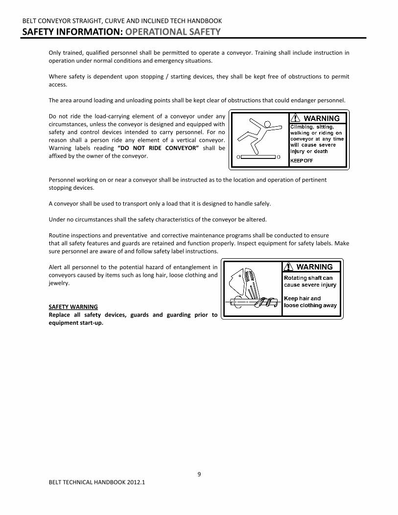
Only trained, qualified personnel shall be permitted to operate a conveyor. Training shall include instruction in operation under normal conditions and emergency situations. Where safety is dependent upon stopping / starting devices, they shall be kept free of obstructions to permit access. The area around loading and unloading points shall be kept clear of obstructions that could endanger personnel. Do not ride the load-carrying element of a conveyor under any circumstances, unless the conveyor is designed and equipped with safety and control devices intended to carry personnel. For no reason shall a person ride any element of a vertical conveyor. Warning labels reading “DO NOT RIDE CONVEYOR” shall be affixed by the owner of the conveyor. Personnel working on or near a conveyor shall be instructed as to the location and operation of pertinent stopping devices. A conveyor shall be used to transport only a load that it is designed to handle safely. Under no circumstances shall the safety characteristics of the conveyor be altered. Routine inspections and preventative and corrective maintenance programs shall be conducted to ensure that all safety features and guards are retained and function properly. Inspect equipment for safety labels. Make sure personnel are aware of and follow safety label instructions. Alert all personnel to the potential hazard of entanglement in conveyors caused by items such as long hair, loose clothing and jewelry. SAFETY WARNING Replace all safety devices, guards and guarding prior to equipment start-up.
10 BELT TECHNICAL HANDBOOK 2012.1
1) MAINTENANCE (REPAIR) Maintenance and service shall be performed by trained, qualified personnel only.
Where lack of maintenance and service would cause a hazardous condition, the user shall establish a maintenance program to ensure that conveyor components are maintained in a condition that does not constitute a hazard to personnel.
No maintenance or service shall be performed when a conveyor is in operation. See “Lubrication” and “Adjustment or Maintenance During Operation” for exceptions. When a conveyor is stopped for maintenance or service, the starting devices, prime mover, powered accessories or electrical must be locked / tagged out in accordance with a formalized procedure designed to protect all persons or groups involved with the conveyor against an unexpected restart. Personnel should be alerted to the hazard of stored energy, which may exist after the power source is locked out. All safety devices and guards shall be replaced before starting equipment for normal operation.
2) ADJUSTMENT OR MAINTENANCE DURING OPERATION When adjustments or maintenance must be done while equipment is in operation, only trained, qualified
personnel who are aware of the hazards of the conveyor in motion shall be allowed to make adjustments, perform maintenance or service. Conveyors shall NOT be maintained or serviced while in operation unless proper maintenance or service requires the conveyor to be in motion. If conveyor operation is required, personnel shall be made aware of the hazards and how the task may be safely accomplished.
3) LUBRICATION Conveyors shall NOT be lubricated while in operation unless it is impractical to shut them down for
lubrication. Only trained and qualified personnel who are aware of the hazards of the conveyor in motion shall be allowed to lubricate a conveyor that is operating.
Where the drip of lubricants or process liquids on the floor constitutes a hazard, drip pans or other means of
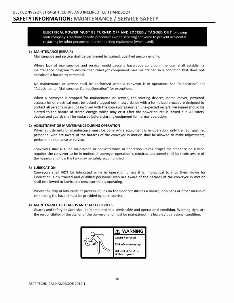
eliminating the hazard must be provided by purchaser(s). 4) MAINTENANCE OF GUARDS AND SAFETY DEVICES Guards and safety devices shall be maintained in a serviceable and operational condition. Warning signs are
the responsibility of the owner of the conveyor and must be maintained in a legible / operational condition.
BELT CONVEYOR STRAIGHT, CURVE AND INCLINED TECH HANDBOOK
SAFETY INFORMATION: MAINTENANCE / SERVICE SAFETY
ELECTRICAL POWER MUST BE TURNED OFF AND LOCKED / TAGGED OU T following your company’s machine specific procedures when servicing conveyor to prevent accidental restarting by other persons or interconnecting equipment (when used).
11 BELT TECHNICAL HANDBOOK 2012.1
BELT CONVEYOR STRAIGHT, CURVE AND INCLINED TECH HANDBOOK
SAFETY INFORMATION: MAINTENANCE / SERVICE SAFETY (Continued)
5) INSPECTIONS Routine inspections with preventative and /or corrective maintenance programs shall be conducted to ensure
that all safety features and devices are maintained and function properly. All personnel shall inspect for hazardous conditions at all times. Remove sharp edges or protruding objects.
Repair or replace worn or damaged parts immediately. 6) CLEANING Where light cleaning and/or casing cleaning are required, they shall be performed by trained personnel. The
conveyor electrical power must be turned off and locked / tagged out following your company’s machine specific procedures. Special attention may be required at feed and discharge points.
7) SAFETY WARNING Replace all safety devices, guards and guarding prior to equipment start-up.

12 BELT TECHNICAL HANDBOOK 2012.1
BELT CONVEYOR STRAIGHT, CURVE AND INCLINED TECH HANDBOOK
SAFETY INFORMATION: BELT CONVEYOR SAFETY INSTRUCTIONS
PARTICULAR DANGER AND PINCH POINTS 1) Any point at which a belt bends around a roller or pulley. 2) Any point where two rollers or pulleys (sheaves for spurs) are close together and produce a “wringer” effect. 3) Any point where accessories are located that also have moving parts.
13 BELT TECHNICAL HANDBOOK 2012.1
BELT CONVEYOR STRAIGHT, CURVE AND INCLINED TECH HANDBOOK
RECEIVING AND INSPECTION: RETURNS, DAMAGES AND SHORTAGES
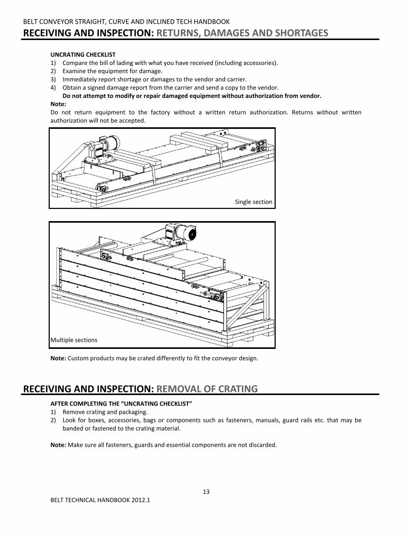
UNCRATING CHECKLIST 1) Compare the bill of lading with what you have received (including accessories). 2) Examine the equipment for damage. 3) Immediately report shortage or damages to the vendor and carrier. 4) Obtain a signed damage report from the carrier and send a copy to the vendor.
Do not attempt to modify or repair damaged equipment without authorization from vendor. Note: Do not return equipment to the factory without a written return authorization. Returns without written authorization will not be accepted.
AFTER COMPLETING THE “UNCRATING CHECKLIST” 1) Remove crating and packaging. 2) Look for boxes, accessories, bags or components such as fasteners, manuals, guard rails etc. that may be
banded or fastened to the crating material. Note: Make sure all fasteners, guards and essential components are not discarded.
MOTOR DRIVEN ROLLER CONVEYOR STRAIGHT AND CURVE TECH HANDBOOK
RECEIVING AND INSPECTION: REMOVAL OF CRATING
Single section
Note: Custom products may be crated differently to fit the conveyor design.
Multiple sections
14 BELT TECHNICAL HANDBOOK 2012.1
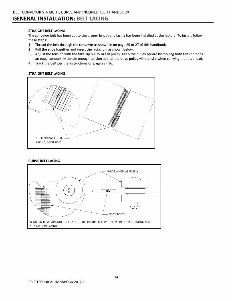
STRAIGHT BELT LACING
BELT CONVEYOR STRAIGHT, CURVE AND INCLINED TECH HANDBOOK
GENERAL INSTALLATION: BELT LACING
STRAIGHT BELT LACING The conveyor belt has been cut to the proper length and lacing has been installed at the factory. To install, follow these steps: 1) Thread the belt through the conveyor as shown in on page 25 or 27 of this handbook. 2) Pull the ends together and insert the lacing pin as shown below. 3) Adjust the tension with the take-up pulley or tail pulley. Keep the pulley square by moving both tension bolts
an equal amount. Maintain enough tension so that the drive pulley will not slip when carrying the rated load. 4) Track the belt per the instructions on page 29 - 36.
CURVE BELT LACING
BELT LACING
GUIDE WHEEL ASSEMBLY
BEND PIN TO WRAP UNDER BELT AT OUTSIDE RADIUS. THIS WILL KEEP PIN FROM ROTATING AND
SLIDING INTO LACING.
TUCK PIN BACK INTO
LACING, BOTH SIDES
15 BELT TECHNICAL HANDBOOK 2012.1
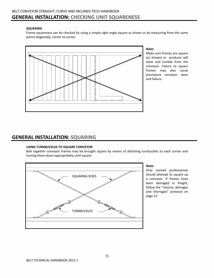
SQUARING Frame squareness can be checked by using a simple right angle square as shown or by measuring from the same points diagonally, corner to corner.
Note: Make sure frames are square (as shown) or products will skew and tumble from the conveyor. Failure to square frames may also cause premature conveyor wear and failure.
BELT CONVEYOR STRAIGHT, CURVE AND INCLINED TECH HANDBOOK
GENERAL INSTALLATION: CHECKING UNIT SQUARENESS
BELT CONVEYOR STRAIGHT, CURVE AND INCLINED TECH HANDBOOK
GENERAL INSTALLATION: SQUARING
SQUARING RODS
USING TURNBUCKLES TO SQUARE CONVEYOR Bolt together conveyor frames may be brought square by means of attaching turnbuckles to each corner and turning them down appropriately until square.
Note: Only trained professionals should attempt to square up a conveyor. If frames have been damaged in freight, follow the “returns, damages and shortages” protocol on page 13.
TURNBUCKLES
16 BELT TECHNICAL HANDBOOK 2012.1
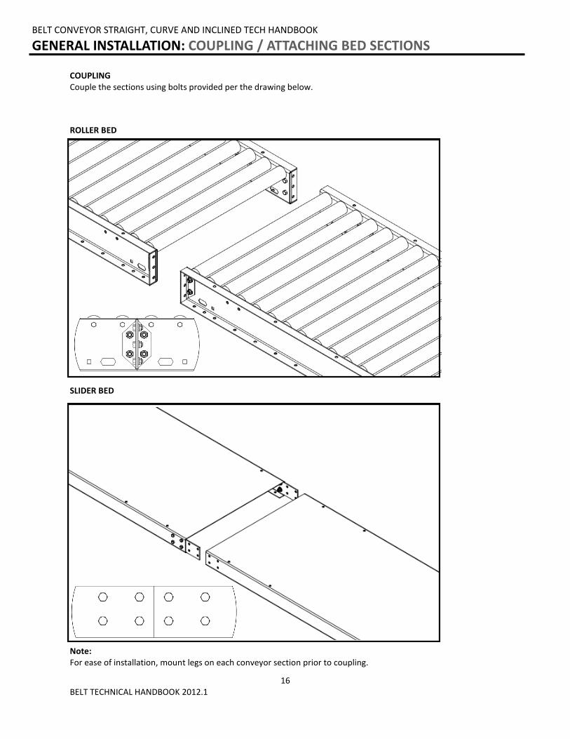
COUPLING Couple the sections using bolts provided per the drawing below.
BELT CONVEYOR STRAIGHT, CURVE AND INCLINED TECH HANDBOOK
GENERAL INSTALLATION: COUPLING / ATTACHING BED SECTIONS
Note: For ease of installation, mount legs on each conveyor section prior to coupling.
ROLLER BED
SLIDER BED
17 BELT TECHNICAL HANDBOOK 2012.1
BELT CONVEYOR STRAIGHT, CURVE AND INCLINED TECH HANDBOOK
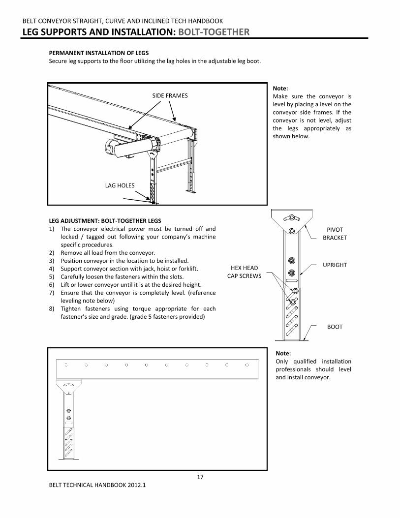
LEG SUPPORTS AND INSTALLATION: BOLT-TOGETHER
PERMANENT INSTALLATION OF LEGS Secure leg supports to the floor utilizing the lag holes in the adjustable leg boot.
Note: Make sure the conveyor is level by placing a level on the conveyor side frames. If the conveyor is not level, adjust the legs appropriately as shown below.
LEG ADJUSTMENT: BOLT-TOGETHER LEGS 1) The conveyor electrical power must be turned off and
locked / tagged out following your company’s machine specific procedures.
2) Remove all load from the conveyor. 3) Position conveyor in the location to be installed. 4) Support conveyor section with jack, hoist or forklift. 5) Carefully loosen the fasteners within the slots. 6) Lift or lower conveyor until it is at the desired height. 7) Ensure that the conveyor is completely level. (reference
leveling note below) 8) Tighten fasteners using torque appropriate for each
fastener’s size and grade. (grade 5 fasteners provided)
Note: Only qualified installation professionals should level and install conveyor.
SIDE FRAMES
LAG HOLES
BOOT
HEX HEAD CAP SCREWS
UPRIGHT
PIVOT BRACKET
18 BELT TECHNICAL HANDBOOK 2012.1
BELT CONVEYOR STRAIGHT, CURVE AND INCLINED TECH HANDBOOK
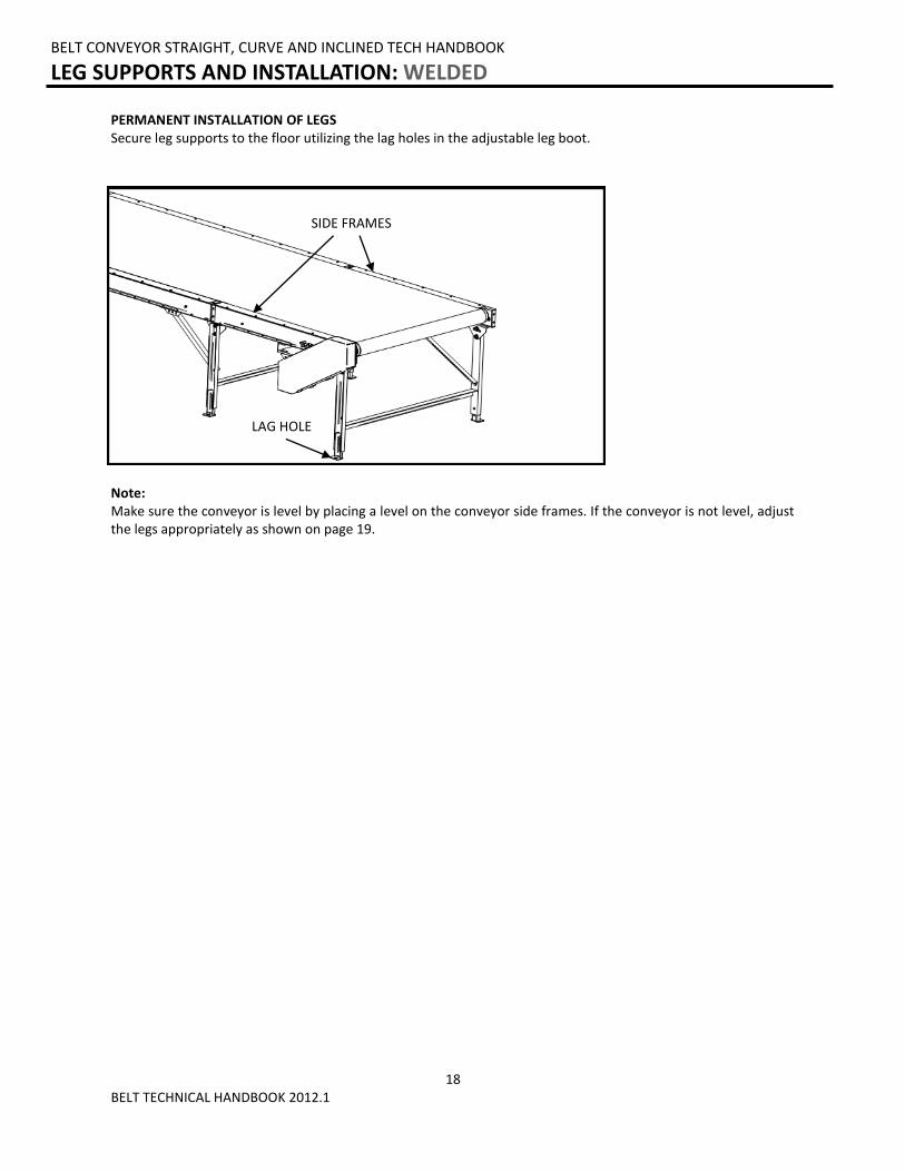
LEG SUPPORTS AND INSTALLATION: WELDED
PERMANENT INSTALLATION OF LEGS Secure leg supports to the floor utilizing the lag holes in the adjustable leg boot.
Note: Make sure the conveyor is level by placing a level on the conveyor side frames. If the conveyor is not level, adjust the legs appropriately as shown on page 19.
SIDE FRAMES
LAG HOLE
19 BELT TECHNICAL HANDBOOK 2012.1
TOP
UPRIGHT
FOOT-PAD
RETAINING BOLT
JACK-BOLT PLATE
TOP
UPRIGHT
FOOT TOP PLATE
FOOT-PAD
JAM NUT
JACK-BOLT
RETAINING BOLT
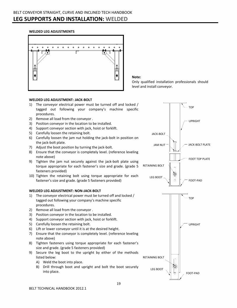
WELDED LEG ADJUSTMENT: JACK-BOLT 1) The conveyor electrical power must be turned off and locked /
tagged out following your company’s machine specific procedures.
2) Remove all load from the conveyor . 3) Position conveyor in the location to be installed. 4) Support conveyor section with jack, hoist or forklift. 5) Carefully loosen the retaining bolt. 6) Carefully loosen the jam nut holding the jack-bolt in position on
the jack-bolt plate. 7) Adjust the boot position by turning the jack-bolt. 8) Ensure that the conveyor is completely level. (reference leveling
note above) 9) Tighten the jam nut securely against the jack-bolt plate using
torque appropriate for each fastener’s size and grade. (grade 5 fasteners provided)
10) Tighten the retaining bolt using torque appropriate for each fastener’s size and grade. (grade 5 fasteners provided)
WELDED LEG ADJUSTMENT: NON-JACK-BOLT 1) The conveyor electrical power must be turned off and locked /
tagged out following your company’s machine specific procedures.
2) Remove all load from the conveyor . 3) Position conveyor in the location to be installed. 4) Support conveyor section with jack, hoist or forklift. 5) Carefully loosen the retaining bolt. 6) Lift or lower conveyor until it is at the desired height. 7) Ensure that the conveyor is completely level. (reference leveling
note above) 8) Tighten fasteners using torque appropriate for each fastener’s
size and grade. (grade 5 fasteners provided) 9) Secure the leg boot to the upright by either of the methods
listed below: A) Weld the boot into place. B) Drill through boot and upright and bolt the boot securely
into place.
WELDED LEG ADJUSTMENTS
Note: Only qualified installation professionals should level and install conveyor.
LEG BOOT
LEG BOOT
BELT CONVEYOR STRAIGHT, CURVE AND INCLINED TECH HANDBOOK
LEG SUPPORTS AND INSTALLATION: WELDED
20 BELT TECHNICAL HANDBOOK 2012.1
BELT CONVEYOR STRAIGHT, CURVE AND INCLINED TECH HANDBOOK
KNEE BRACES, CASTERS AND CEILING HANGERS: INSTALLING KNEE BRACES
MOTOR DRIVEN ROLLER CONVEYOR STRAIGHT AND CURVE TECH HANDBOOK
KNEE BRACES, CASTERS AND CEILING HANGERS: INSTALLING CASTERS
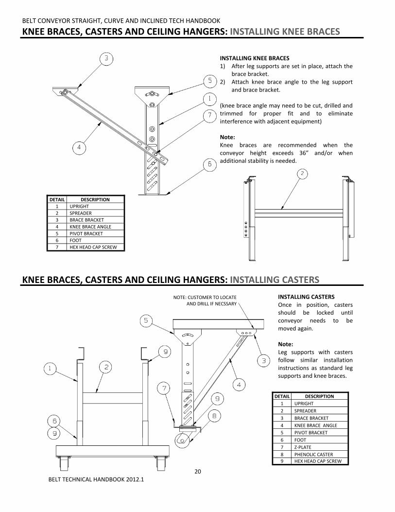
INSTALLING KNEE BRACES 1) After leg supports are set in place, attach the
brace bracket. 2) Attach knee brace angle to the leg support
and brace bracket. (knee brace angle may need to be cut, drilled and trimmed for proper fit and to eliminate interference with adjacent equipment) Note: Knee braces are recommended when the conveyor height exceeds 36” and/or when additional stability is needed.
INSTALLING CASTERS Once in position, casters should be locked until conveyor needs to be moved again. Note: Leg supports with casters follow similar installation instructions as standard leg supports and knee braces.
NOTE: CUSTOMER TO LOCATE AND DRILL IF NECSSARY
DETAIL DESCRIPTION
1 UPRIGHT
2 SPREADER
3 BRACE BRACKET
4 KNEE BRACE ANGLE
5 PIVOT BRACKET
6 FOOT
7 HEX HEAD CAP SCREW
DETAIL DESCRIPTION
1 UPRIGHT
2 SPREADER
3 BRACE BRACKET
4 KNEE BRACE ANGLE
5 PIVOT BRACKET
6 FOOT
7 Z-PLATE
8 PHENOLIC CASTER
9 HEX HEAD CAP SCREW
21 BELT TECHNICAL HANDBOOK 2012.1
BELT CONVEYOR STRAIGHT, CURVE AND INCLINED TECH HANDBOOK
KNEE BRACES, CASTERS AND CEILING HANGERS: INSTALLING WELDED KNEE BRACES
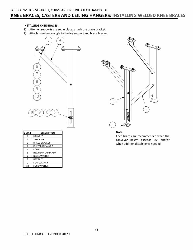
INSTALLING KNEE BRACES 1) After leg supports are set in place, attach the brace bracket. 2) Attach knee brace angle to the leg support and brace bracket.
Note: Knee braces are recommended when the conveyor height exceeds 36” and/or when additional stability is needed.
DETAIL DESCRIPTION
1 UPRIGHT
2 SPREADER
3 BRACE BRACKET
4 KNEEBRACE ANGLE
5 FOOT
6 HEX HEAD CAP SCREW
7 BEVEL WASHER
8 HEX NUT
9 FLAT WASHER
10 LOCK WASHER
22 BELT TECHNICAL HANDBOOK 2012.1
BELT CONVEYOR STRAIGHT, CURVE AND INCLINED TECH HANDBOOK
KNEE BRACES, CASTERS AND CEILING HANGERS: INSTALLING CEILING HANGERS
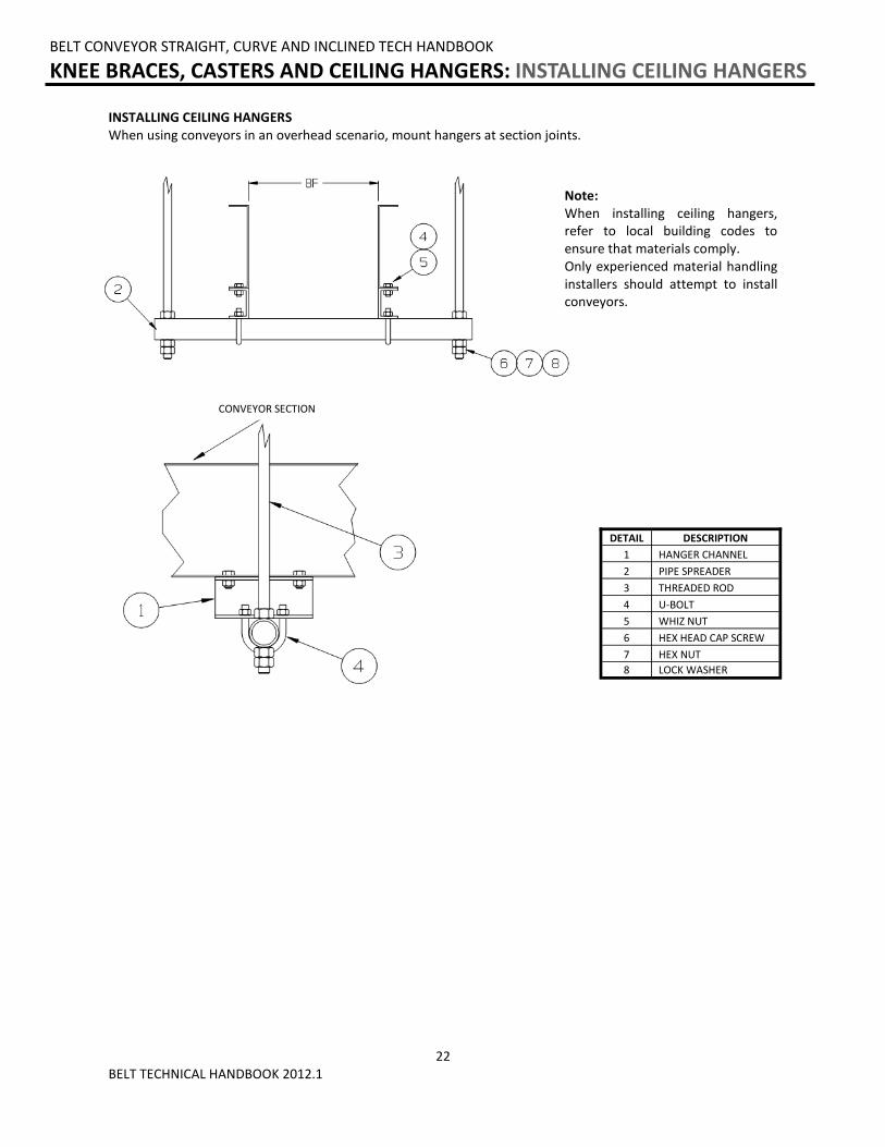
INSTALLING CEILING HANGERS When using conveyors in an overhead scenario, mount hangers at section joints.
Note: When installing ceiling hangers, refer to local building codes to ensure that materials comply. Only experienced material handling installers should attempt to install conveyors.
CONVEYOR SECTION
DETAIL DESCRIPTION
1 HANGER CHANNEL
2 PIPE SPREADER
3 THREADED ROD
4 U-BOLT
5 WHIZ NUT
6 HEX HEAD CAP SCREW
7 HEX NUT
8 LOCK WASHER
23 BELT TECHNICAL HANDBOOK 2012.1
BELT CONVEYOR STRAIGHT, CURVE AND INCLINED TECH HANDBOOK
MULTI-TIER SUPPORTS: INSTALLATION OF MULTI-TIER SUPPORTS
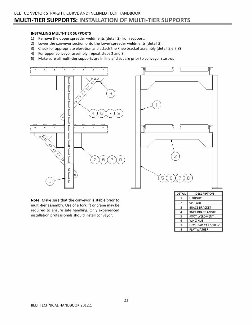
Note: Make sure that the conveyor is stable prior to multi-tier assembly. Use of a forklift or crane may be required to ensure safe handling. Only experienced installation professionals should install conveyor.
INSTALLING MULTI-TIER SUPPORTS 1) Remove the upper spreader weldments (detail 3) from support. 2) Lower the conveyor section onto the lower spreader weldments (detail 3). 3) Check for appropriate elevation and attach the knee bracket assembly (detail 5,6,7,8) 4) For upper conveyor assembly, repeat steps 2 and 3. 5) Make sure all multi-tier supports are in line and square prior to conveyor start-up.
DETAIL DESCRIPTION
1 UPRIGHT
2 SPREADER
3 BRACE BRACKET
4 KNEE BRACE ANGLE
5 FOOT WELDMENT
6 WHIZ NUT
7 HEX HEAD CAP SCREW
8 FLAT WASHER
24 BELT TECHNICAL HANDBOOK 2012.1
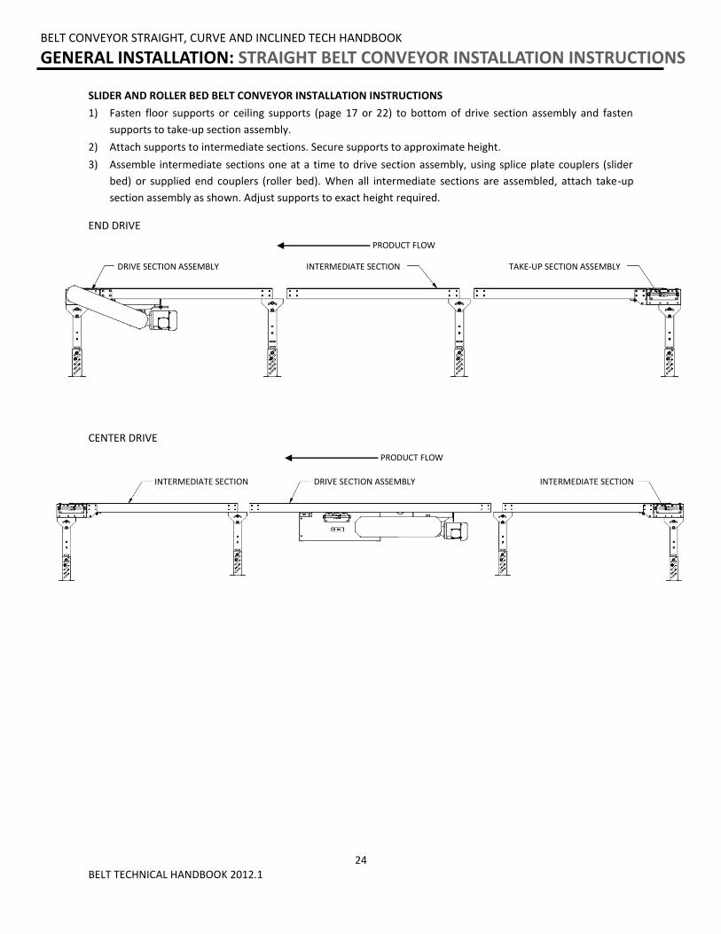
SLIDER AND ROLLER BED BELT CONVEYOR INSTALLATION INSTRUCTIONS
1) Fasten floor supports or ceiling supports (page 17 or 22) to bottom of drive section assembly and fasten
supports to take-up section assembly.
2) Attach supports to intermediate sections. Secure supports to approximate height.
3) Assemble intermediate sections one at a time to drive section assembly, using splice plate couplers (slider
bed) or supplied end couplers (roller bed). When all intermediate sections are assembled, attach take-up
section assembly as shown. Adjust supports to exact height required.
BELT CONVEYOR STRAIGHT, CURVE AND INCLINED TECH HANDBOOK
GENERAL INSTALLATION: STRAIGHT BELT CONVEYOR INSTALLATION INSTRUCTIONS
END DRIVE
CENTER DRIVE
TAKE-UP SECTION ASSEMBLY
PRODUCT FLOW
DRIVE SECTION ASSEMBLY INTERMEDIATE SECTION INTERMEDIATE SECTION
DRIVE SECTION ASSEMBLY INTERMEDIATE SECTION
PRODUCT FLOW
25 BELT TECHNICAL HANDBOOK 2012.1
BELT CONVEYOR STRAIGHT, CURVE AND INCLINED TECH HANDBOOK
GENERAL INSTALLATION: STRAIGHT BELT CONVEYOR INSTALLATION INSTRUCTIONS
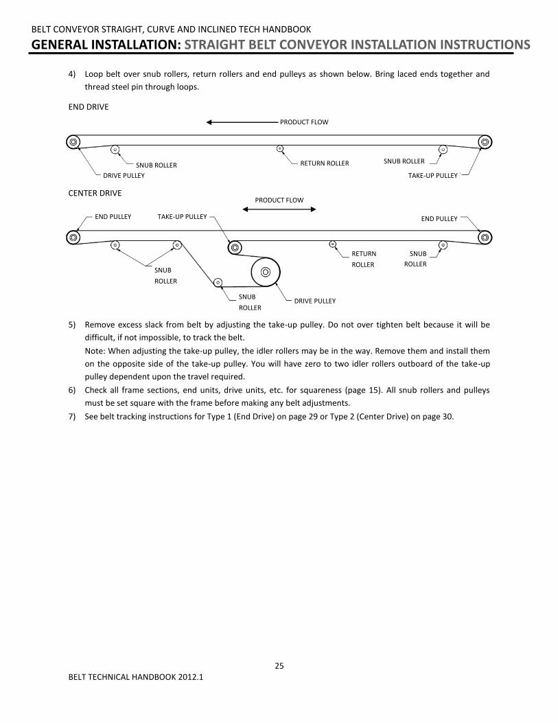
5) Remove excess slack from belt by adjusting the take-up pulley. Do not over tighten belt because it will be
difficult, if not impossible, to track the belt.
Note: When adjusting the take-up pulley, the idler rollers may be in the way. Remove them and install them
on the opposite side of the take-up pulley. You will have zero to two idler rollers outboard of the take-up
pulley dependent upon the travel required.
6) Check all frame sections, end units, drive units, etc. for squareness (page 15). All snub rollers and pulleys
must be set square with the frame before making any belt adjustments.
7) See belt tracking instructions for Type 1 (End Drive) on page 29 or Type 2 (Center Drive) on page 30.
CENTER DRIVE PRODUCT FLOW
END PULLEY
RETURN
ROLLER
END PULLEY
SNUB
ROLLER
TAKE-UP PULLEY
DRIVE PULLEY
SNUB
ROLLER
SNUB
ROLLER
4) Loop belt over snub rollers, return rollers and end pulleys as shown below. Bring laced ends together and
thread steel pin through loops.
DRIVE PULLEY
RETURN ROLLER SNUB ROLLER
SNUB ROLLER
TAKE-UP PULLEY
PRODUCT FLOW
END DRIVE
26 BELT TECHNICAL HANDBOOK 2012.1
BELT CONVEYOR STRAIGHT, CURVE AND INCLINED TECH HANDBOOK
GENERAL INSTALLATION: INCLINED BELT CONVEYOR INSTALLATION INSTRUCTIONS
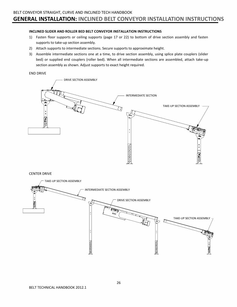
INCLINED SLIDER AND ROLLER BED BELT CONVEYOR INSTALLATION INSTRUCTIONS
1) Fasten floor supports or ceiling supports (page 17 or 22) to bottom of drive section assembly and fasten
supports to take-up section assembly.
2) Attach supports to intermediate sections. Secure supports to approximate height.
3) Assemble intermediate sections one at a time, to drive section assembly, using splice plate couplers (slider
bed) or supplied end couplers (roller bed). When all intermediate sections are assembled, attach take-up
section assembly as shown. Adjust supports to exact height required.
END DRIVE
CENTER DRIVE
INTERMEDIATE SECTION
INTERMEDIATE SECTION ASSEMBLY
TAKE-UP SECTION ASSEMBLY
DRIVE SECTION ASSEMBLY
TAKE-UP SECTION ASSEMBLY
DRIVE SECTION ASSEMBLY
TAKE-UP SECTION ASSEMBLY
27 BELT TECHNICAL HANDBOOK 2012.1
BELT CONVEYOR STRAIGHT, CURVE AND INCLINED TECH HANDBOOK
GENERAL INSTALLATION: INCLINED BELT CONVEYOR INSTALLATION INSTRUCTIONS
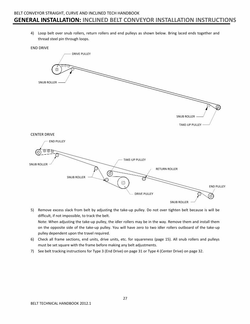
4) Loop belt over snub rollers, return rollers and end pulleys as shown below. Bring laced ends together and
thread steel pin through loops.
END DRIVE
5) Remove excess slack from belt by adjusting the take-up pulley. Do not over tighten belt because is will be
difficult, if not impossible, to track the belt.
Note: When adjusting the take-up pulley, the idler rollers may be in the way. Remove them and install them
on the opposite side of the take-up pulley. You will have zero to two idler rollers outboard of the take-up
pulley dependent upon the travel required.
6) Check all frame sections, end units, drive units, etc. for squareness (page 15). All snub rollers and pulleys
must be set square with the frame before making any belt adjustments.
7) See belt tracking instructions for Type 3 (End Drive) on page 31 or Type 4 (Center Drive) on page 32.
SNUB ROLLER
DRIVE PULLEY
TAKE-UP PULLEY
SNUB ROLLER
END PULLEY
END PULLEY
CENTER DRIVE
RETURN ROLLER
SNUB ROLLER
SNUB ROLLER
TAKE-UP PULLEY
DRIVE PULLEY
SNUB ROLLER
28 BELT TECHNICAL HANDBOOK 2012.1
BELT CONVEYOR STRAIGHT, CURVE AND INCLINED TECH HANDBOOK
GENERAL INSTALLATION: INCLINED BELT CONVEYOR INSTALLATION INSTRUCTIONS
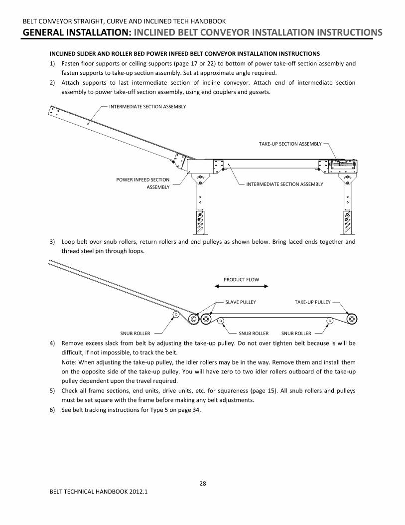
INCLINED SLIDER AND ROLLER BED POWER INFEED BELT CONVEYOR INSTALLATION INSTRUCTIONS
1) Fasten floor supports or ceiling supports (page 17 or 22) to bottom of power take-off section assembly and
fasten supports to take-up section assembly. Set at approximate angle required.
2) Attach supports to last intermediate section of incline conveyor. Attach end of intermediate section
assembly to power take-off section assembly, using end couplers and gussets.
3) Loop belt over snub rollers, return rollers and end pulleys as shown below. Bring laced ends together and
thread steel pin through loops.
4) Remove excess slack from belt by adjusting the take-up pulley. Do not over tighten belt because is will be
difficult, if not impossible, to track the belt.
Note: When adjusting the take-up pulley, the idler rollers may be in the way. Remove them and install them
on the opposite side of the take-up pulley. You will have zero to two idler rollers outboard of the take-up
pulley dependent upon the travel required.
5) Check all frame sections, end units, drive units, etc. for squareness (page 15). All snub rollers and pulleys
must be set square with the frame before making any belt adjustments.
6) See belt tracking instructions for Type 5 on page 34.
POWER INFEED SECTION
ASSEMBLY
SNUB ROLLER SNUB ROLLER
SLAVE PULLEY
SNUB ROLLER
TAKE-UP PULLEY
INTERMEDIATE SECTION ASSEMBLY
INTERMEDIATE SECTION ASSEMBLY
TAKE-UP SECTION ASSEMBLY
PRODUCT FLOW
29 BELT TECHNICAL HANDBOOK 2012.1
BELT CONVEYOR STRAIGHT, CURVE AND INCLINED TECH HANDBOOK
INSTRUCTIONS FOR BELT TRACKING: BELT TYPE 1
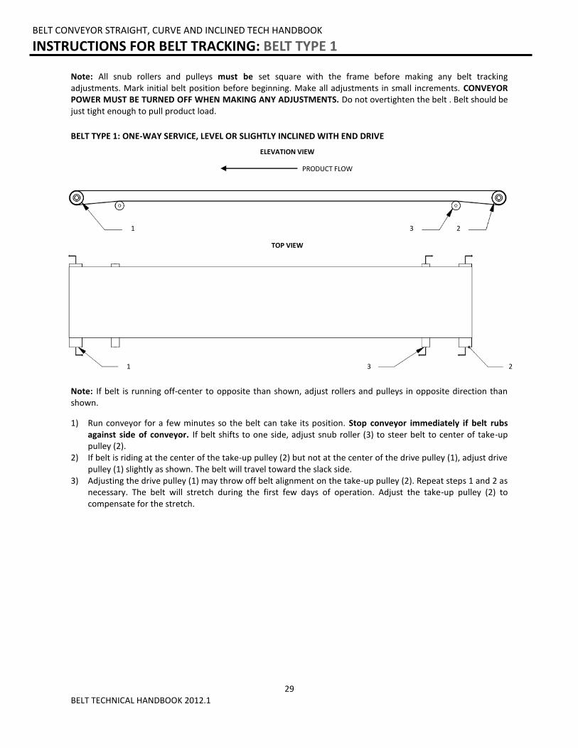
BELT TYPE 1: ONE-WAY SERVICE, LEVEL OR SLIGHTLY INCLINED WITH END DRIVE
1) Run conveyor for a few minutes so the belt can take its position. Stop conveyor immediately if belt rubs against side of conveyor. If belt shifts to one side, adjust snub roller (3) to steer belt to center of take-up pulley (2).
2) If belt is riding at the center of the take-up pulley (2) but not at the center of the drive pulley (1), adjust drive pulley (1) slightly as shown. The belt will travel toward the slack side.
3) Adjusting the drive pulley (1) may throw off belt alignment on the take-up pulley (2). Repeat steps 1 and 2 as necessary. The belt will stretch during the first few days of operation. Adjust the take-up pulley (2) to compensate for the stretch.
Note: If belt is running off-center to opposite than shown, adjust rollers and pulleys in opposite direction than shown.
Note: All snub rollers and pulleys must be set square with the frame before making any belt tracking adjustments. Mark initial belt position before beginning. Make all adjustments in small increments. CONVEYOR POWER MUST BE TURNED OFF WHEN MAKING ANY ADJUSTMENTS. Do not overtighten the belt . Belt should be just tight enough to pull product load.
ELEVATION VIEW
PRODUCT FLOW
1 2 3
1 2 3
TOP VIEW
30 BELT TECHNICAL HANDBOOK 2012.1
1
2
3 5
6 7
4
Note: If belt is running off-center to opposite than shown, adjust rollers and pulleys in opposite direction than shown.
BELT CONVEYOR STRAIGHT, CURVE AND INCLINED TECH HANDBOOK
INSTRUCTIONS FOR BELT TRACKING: BELT TYPE 2
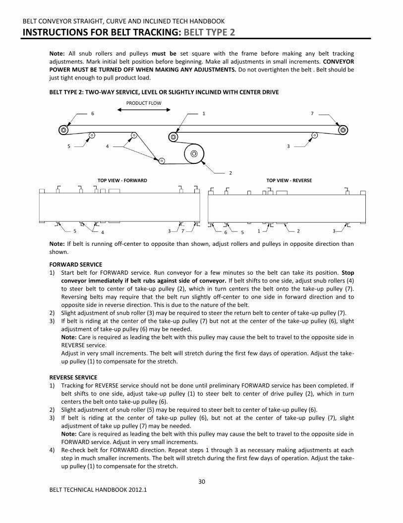
BELT TYPE 2: TWO-WAY SERVICE, LEVEL OR SLIGHTLY INCLINED WITH CENTER DRIVE
FORWARD SERVICE 1) Start belt for FORWARD service. Run conveyor for a few minutes so the belt can take its position. Stop
conveyor immediately if belt rubs against side of conveyor. If belt shifts to one side, adjust snub rollers (4) to steer belt to center of take-up pulley (2), which in turn centers the belt onto the take-up pulley (7). Reversing belts may require that the belt run slightly off-center to one side in forward direction and to opposite side in reverse direction. This is due to the nature of the belt.
2) Slight adjustment of snub roller (3) may be required to steer the return belt to center of take-up pulley (7). 3) If belt is riding at the center of the take-up pulley (7) but not at the center of the take-up pulley (6), slight
adjustment of take-up pulley (6) may be needed. Note: Care is required as leading the belt with this pulley may cause the belt to travel to the opposite side in REVERSE service. Adjust in very small increments. The belt will stretch during the first few days of operation. Adjust the take-up pulley (1) to compensate for the stretch.
REVERSE SERVICE 1) Tracking for REVERSE service should not be done until preliminary FORWARD service has been completed. If
belt shifts to one side, adjust take-up pulley (1) to steer belt to center of drive pulley (2), which in turn centers the belt onto take-up pulley (6).
2) Slight adjustment of snub roller (5) may be required to steer belt to center of take-up pulley (6). 3) If belt is riding at the center of take-up pulley (6), but not at the center of take-up pulley (7), slight
adjustment of take up pulley (7) may be needed. Note: Care is required as leading the belt with this pulley may cause the belt to travel to the opposite side in FORWARD service. Adjust in very small increments.
4) Re-check belt for FORWARD direction. Repeat steps 1 through 3 as necessary making adjustments at each step in much smaller increments. The belt will stretch during the first few days of operation. Adjust the take-up pulley (1) to compensate for the stretch.
Note: All snub rollers and pulleys must be set square with the frame before making any belt tracking adjustments. Mark initial belt position before beginning. Make all adjustments in small increments. CONVEYOR POWER MUST BE TURNED OFF WHEN MAKING ANY ADJUSTMENTS. Do not overtighten the belt . Belt should be just tight enough to pull product load.
TOP VIEW - FORWARD
PRODUCT FLOW
TOP VIEW - REVERSE
3 4 5 7 6 3 2 5 1
31 BELT TECHNICAL HANDBOOK 2012.1
BELT CONVEYOR STRAIGHT, CURVE AND INCLINED TECH HANDBOOK
INSTRUCTIONS FOR BELT TRACKING: BELT TYPE 3
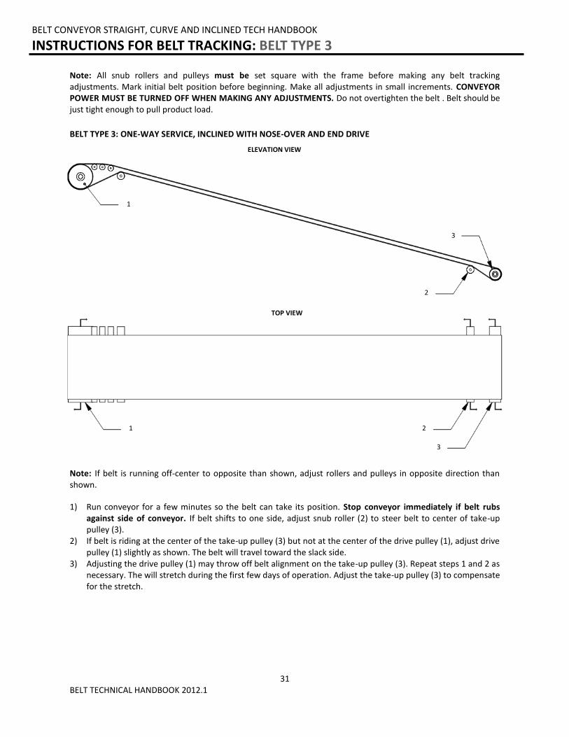
BELT TYPE 3: ONE-WAY SERVICE, INCLINED WITH NOSE-OVER AND END DRIVE
1) Run conveyor for a few minutes so the belt can take its position. Stop conveyor immediately if belt rubs against side of conveyor. If belt shifts to one side, adjust snub roller (2) to steer belt to center of take-up pulley (3).
2) If belt is riding at the center of the take-up pulley (3) but not at the center of the drive pulley (1), adjust drive pulley (1) slightly as shown. The belt will travel toward the slack side.
3) Adjusting the drive pulley (1) may throw off belt alignment on the take-up pulley (3). Repeat steps 1 and 2 as necessary. The will stretch during the first few days of operation. Adjust the take-up pulley (3) to compensate for the stretch.
Note: All snub rollers and pulleys must be set square with the frame before making any belt tracking adjustments. Mark initial belt position before beginning. Make all adjustments in small increments. CONVEYOR POWER MUST BE TURNED OFF WHEN MAKING ANY ADJUSTMENTS. Do not overtighten the belt . Belt should be just tight enough to pull product load.
Note: If belt is running off-center to opposite than shown, adjust rollers and pulleys in opposite direction than shown.
1
3
ELEVATION VIEW
TOP VIEW
1 2
3
2
32 BELT TECHNICAL HANDBOOK 2012.1
BELT CONVEYOR STRAIGHT, CURVE AND INCLINED TECH HANDBOOK
INSTRUCTIONS FOR BELT TRACKING: BELT TYPE 4
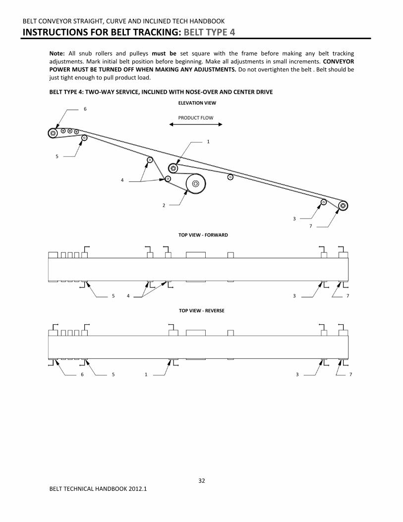
BELT TYPE 4: TWO-WAY SERVICE, INCLINED WITH NOSE-OVER AND CENTER DRIVE
Note: All snub rollers and pulleys must be set square with the frame before making any belt tracking adjustments. Mark initial belt position before beginning. Make all adjustments in small increments. CONVEYOR POWER MUST BE TURNED OFF WHEN MAKING ANY ADJUSTMENTS. Do not overtighten the belt . Belt should be just tight enough to pull product load.
6
7
ELEVATION VIEW
5
2
4
1
TOP VIEW - FORWARD
TOP VIEW - REVERSE
7 3 5
6 7 3 5 1
PRODUCT FLOW
3
4
33 BELT TECHNICAL HANDBOOK 2012.1
BELT CONVEYOR STRAIGHT, CURVE AND INCLINED TECH HANDBOOK
INSTRUCTIONS FOR BELT TRACKING: BELT TYPE 4
BELT TYPE 4: TWO-WAY SERVICE, INCLINED WITH NOSE-OVER AND CENTER DRIVE
FORWARD SERVICE 1) Start belt for FORWARD service. Run conveyor for a few minutes so the belt can take its position. Stop
conveyor immediately if belt rubs against side of conveyor. If belt shifts to one side, adjust snub rollers (4) to steer belt to center of take-up pulley (2), which in turn centers the belt onto the take-up pulley (7). Reversing belts may require that the belt run slightly off-center to one side in forward direction and to opposite side in reverse direction. This is due to the nature of the belt.
2) Slight adjustment of snub roller (3) may be required to steer the return belt to center of take-up pulley (7). 3) If belt is riding at the center of the take-up pulley (7) but not at the center of the take-up pulley (6), slight
adjustment of take-up pulley (6) may be needed. Note: Care is required as leading the belt with this pulley may cause the belt to travel to the opposite side in REVERSE service. Adjust in very small increments. The belt will stretch during the first few days of operation. Adjust the take-up pulley (1) to compensate for the stretch.
REVERSE SERVICE 1) Tracking for REVERSE service should not be done until preliminary FORWARD service has been completed. If
belt shifts to one side, adjust take-up pulley (1) to steer belt to center of drive pulley (2), which in turn centers the belt onto take-up pulley (6).
2) Slight adjustment of snub roller (5) may be required to steer belt to center of take-up pulley (6). 3) If belt is riding at the center of take-up pulley (6), but not at the center of take-up pulley (7), slight
adjustment of take up pulley (7) may be needed. Note: Care is required as leading the belt with this pulley may cause the belt to travel to the opposite side in FORWARD service. Adjust in very small increments.
4) Re-check belt for FORWARD direction. Repeat steps 1 through 3 as necessary making adjustments at each step in much smaller increments. The belt will stretch during the first few days of operation. Adjust the take-up pulley (1) to compensate for the stretch.
Note: All snub rollers and pulleys must be set square with the frame before making any belt tracking adjustments. Mark initial belt position before beginning. Make all adjustments in small increments. CONVEYOR POWER MUST BE TURNED OFF WHEN MAKING ANY ADJUSTMENTS. Do not overtighten the belt . Belt should be just tight enough to pull product load.
34 BELT TECHNICAL HANDBOOK 2012.1
BELT CONVEYOR STRAIGHT, CURVE AND INCLINED TECH HANDBOOK
INSTRUCTIONS FOR BELT TRACKING: BELT TYPE 5
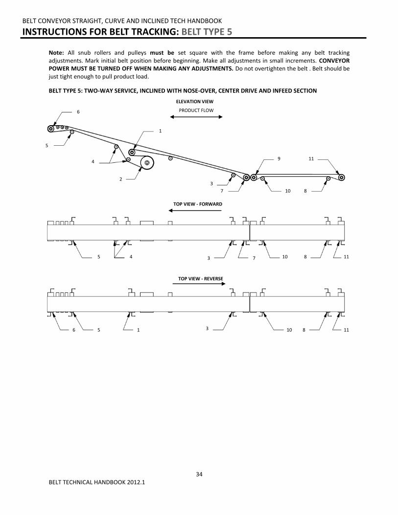
BELT TYPE 5: TWO-WAY SERVICE, INCLINED WITH NOSE-OVER, CENTER DRIVE AND INFEED SECTION
Note: All snub rollers and pulleys must be set square with the frame before making any belt tracking adjustments. Mark initial belt position before beginning. Make all adjustments in small increments. CONVEYOR POWER MUST BE TURNED OFF WHEN MAKING ANY ADJUSTMENTS. Do not overtighten the belt . Belt should be just tight enough to pull product load.
ELEVATION VIEW
TOP VIEW - FORWARD
TOP VIEW - REVERSE
6 3 10 5 8 11 1
PRODUCT FLOW
6
7
3
5
2
4 9
1
10 8
11
7 3 10 5 8 11 4
35 BELT TECHNICAL HANDBOOK 2012.1
BELT CONVEYOR STRAIGHT, CURVE AND INCLINED TECH HANDBOOK
INSTRUCTIONS FOR BELT TRACKING: BELT TYPE 5
BELT TYPE 5: TWO-WAY SERVICE, INCLINED WITH NOSE-OVER, CENTER DRIVE AND INFEED SECTION
FORWARD SERVICE INCLINE CONVEYOR: 1) Start belt for FORWARD service. Run conveyor for a few minutes so the belt can take its position. Stop
conveyor immediately if belt rubs against side of conveyor. If belt shifts to one side, adjust snub rollers (4) to steer belt to center of take-up pulley (2), which in turn centers the belt onto the take-up pulley (7). Reversing belts may require that the belt run slightly off-center to one side in forward direction and to opposite side in reverse direction. This is due to the nature of the belt.
2) Slight adjustment of snub roller (3) may be required to steer the return belt to center of take-up pulley (7). 3) If belt is riding at the center of the take-up pulley (7) but not at the center of the take-up pulley (6), slight
adjustment of take-up pulley (6) may be needed. Note: Care is required as leading the belt with this pulley may cause the belt to travel to the opposite side in REVERSE service. Adjust in very small increments. The belt will stretch during the first few days of operation. Adjust the take-up pulley (1) to compensate for the stretch.
INFEED CONVEYOR: 1) To track infeed section, adjust snub roller (8) to steer belt to the center of take-up pulley (11). 2) If belt is riding at the center of take-up pulley (11), but not at the center of the take-up pulley (9), snub roller
(10) must be adjusted slightly. Additional skewing of take-up pulley (11) may be required. Note: Care is required as leading the belt with this pulley may cause the belt to travel to the opposite side in REVERSE service. Adjust in very small increments. The belt will stretch during the first few days of operation. Adjust the take-up pulley (11) to compensate for the stretch.
REVERSE SERVICE DECLINE CONVEYOR: 1) Tracking for REVERSE service should not be done until preliminary FORWARD service has been completed. If
belt shifts to one side, adjust take-up pulley (1) to steer belt to center of drive pulley (2), which in turn centers the belt onto take-up pulley (6).
2) Slight adjustment of snub roller (5) may be required to steer belt to center of take-up pulley (6). 3) If belt is riding at the center of take-up pulley (6), but not at the center of take-up pulley (7), slight
adjustment of take up pulley (7) may be needed. Note: Care is required as leading the belt with this pulley may cause the belt to travel to the opposite side in FORWARD service. Adjust in very small increments.
DISCHARGE SECTION: 1) To track discharge section, adjust snub roller (10) to steer belt to center of take-up pulley (9). 2) If belt is riding at the center of take-up pulley (9), but not at the center of take-up pulley (11), snub roller (10)
must be adjusted slightly. Additional skewing of take-up pulley (9) may be required. Note: Care is required as leading the belt with this pulley may cause the belt to travel to the opposite side in FORWARD service.
3) Re-check belt for FORWARD direction. Repeat steps 1 through 3 as necessary making adjustments at each step in much smaller increments. The belt will stretch during the first few days of operation. Adjust the take-up pulley (11) to compensate for the stretch.
Note: All snub rollers and pulleys must be set square with the frame before making any belt tracking adjustments. Mark initial belt position before beginning. Make all adjustments in small increments. CONVEYOR POWER MUST BE TURNED OFF WHEN MAKING ANY ADJUSTMENTS. Do not overtighten the belt . Belt should be just tight enough to pull product load.
36 BELT TECHNICAL HANDBOOK 2012.1
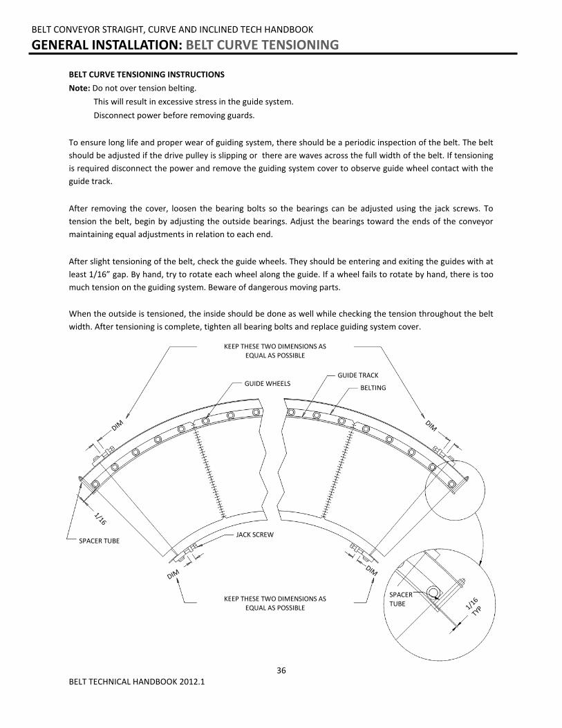
BELT CURVE TENSIONING INSTRUCTIONS
Note: Do not over tension belting.
This will result in excessive stress in the guide system.
Disconnect power before removing guards.
To ensure long life and proper wear of guiding system, there should be a periodic inspection of the belt. The belt
should be adjusted if the drive pulley is slipping or there are waves across the full width of the belt. If tensioning
is required disconnect the power and remove the guiding system cover to observe guide wheel contact with the
guide track.
After removing the cover, loosen the bearing bolts so the bearings can be adjusted using the jack screws. To
tension the belt, begin by adjusting the outside bearings. Adjust the bearings toward the ends of the conveyor
maintaining equal adjustments in relation to each end.
After slight tensioning of the belt, check the guide wheels. They should be entering and exiting the guides with at
least 1/16” gap. By hand, try to rotate each wheel along the guide. If a wheel fails to rotate by hand, there is too
much tension on the guiding system. Beware of dangerous moving parts.
When the outside is tensioned, the inside should be done as well while checking the tension throughout the belt
width. After tensioning is complete, tighten all bearing bolts and replace guiding system cover.
BELT CONVEYOR STRAIGHT, CURVE AND INCLINED TECH HANDBOOK
GENERAL INSTALLATION: BELT CURVE TENSIONING
KEEP THESE TWO DIMENSIONS AS EQUAL AS POSSIBLE
GUIDE WHEELS GUIDE TRACK
BELTING
JACK SCREW
KEEP THESE TWO DIMENSIONS AS EQUAL AS POSSIBLE
SPACER TUBE
SPACER TUBE
DIM
1/16
DIM
DIM
DIM
1/16
TYP
37 BELT TECHNICAL HANDBOOK 2012.1
BELT CONVEYOR STRAIGHT, CURVE AND INCLINED TECH HANDBOOK
PRE-START-UP OVERVIEW: PREPARING FOR INITIAL START-UP
1) Review pages 7 through 12 prior to starting any equipment.
2) Verify that conveyor sections, leg supports, etc. were installed properly.
3) Verify that drive chains and sprockets are installed, aligned and tensioned properly.
4) Verify set screws are tight in sprockets, bearings and all components that have them in.
5) Verify that all drive and mounted bearing bolts are fastened securely.
6) Verify that all motor control wiring is connected properly.
7) Verify that conveyor is not loaded with product.
8) Verify that gearboxes are filled with the proper amount of oil or that they were factory filled with lube. (If your conveyor is equipped with a Boston 700 Series Reducer, it is filled with oil, sealed and lubed for life thus requiring no oil changes. Literature provided with equipment will give detailed info on gearbox lube info.)
9) Verify that the gearbox has necessary vent plugs installed if applicable. (If your conveyor is equipped with a Boston 700 Series Reducer, it is supplied with a PosiVent® and no vent plug is required. Literature provided with equipment will give detailed info on gearbox vent plug requirements.)
38 BELT TECHNICAL HANDBOOK 2012.1
BELT CONVEYOR STRAIGHT, CURVE AND INCLINED TECH HANDBOOK
PRE-START-UP OVERVIEW: DRIVE CHAIN AND SPROCKET ALIGNMENT
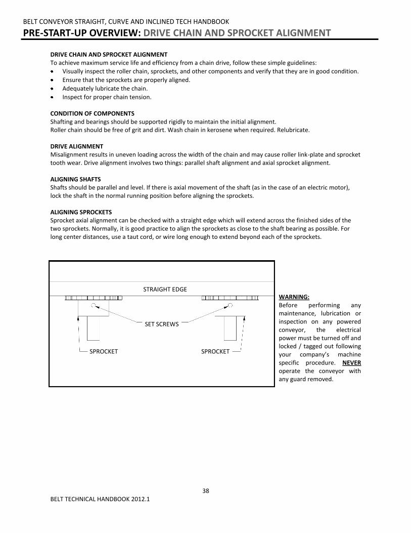
DRIVE CHAIN AND SPROCKET ALIGNMENT To achieve maximum service life and efficiency from a chain drive, follow these simple guidelines:
Visually inspect the roller chain, sprockets, and other components and verify that they are in good condition.
Ensure that the sprockets are properly aligned.
Adequately lubricate the chain.
Inspect for proper chain tension. CONDITION OF COMPONENTS Shafting and bearings should be supported rigidly to maintain the initial alignment. Roller chain should be free of grit and dirt. Wash chain in kerosene when required. Relubricate. DRIVE ALIGNMENT Misalignment results in uneven loading across the width of the chain and may cause roller link-plate and sprocket tooth wear. Drive alignment involves two things: parallel shaft alignment and axial sprocket alignment. ALIGNING SHAFTS Shafts should be parallel and level. If there is axial movement of the shaft (as in the case of an electric motor), lock the shaft in the normal running position before aligning the sprockets. ALIGNING SPROCKETS Sprocket axial alignment can be checked with a straight edge which will extend across the finished sides of the two sprockets. Normally, it is good practice to align the sprockets as close to the shaft bearing as possible. For long center distances, use a taut cord, or wire long enough to extend beyond each of the sprockets.
WARNING: Before performing any maintenance, lubrication or inspection on any powered conveyor, the electrical power must be turned off and locked / tagged out following your company’s machine specific procedure. NEVER operate the conveyor with any guard removed.
STRAIGHT EDGE
SPROCKET SPROCKET
SET SCREWS
39 BELT TECHNICAL HANDBOOK 2012.1
BELT CONVEYOR STRAIGHT, CURVE AND INCLINED TECH HANDBOOK
PRE-START-UP OVERVIEW: DRIVE CHAIN AND SPROCKET TENSION
CHAIN DRIVEN LIVE ROLLER CONVEYOR STRAIGHT AND CURVE TECH HANDBOOK
PRE-START-UP OVERVIEW: GEAR REDUCER VENT PLUG
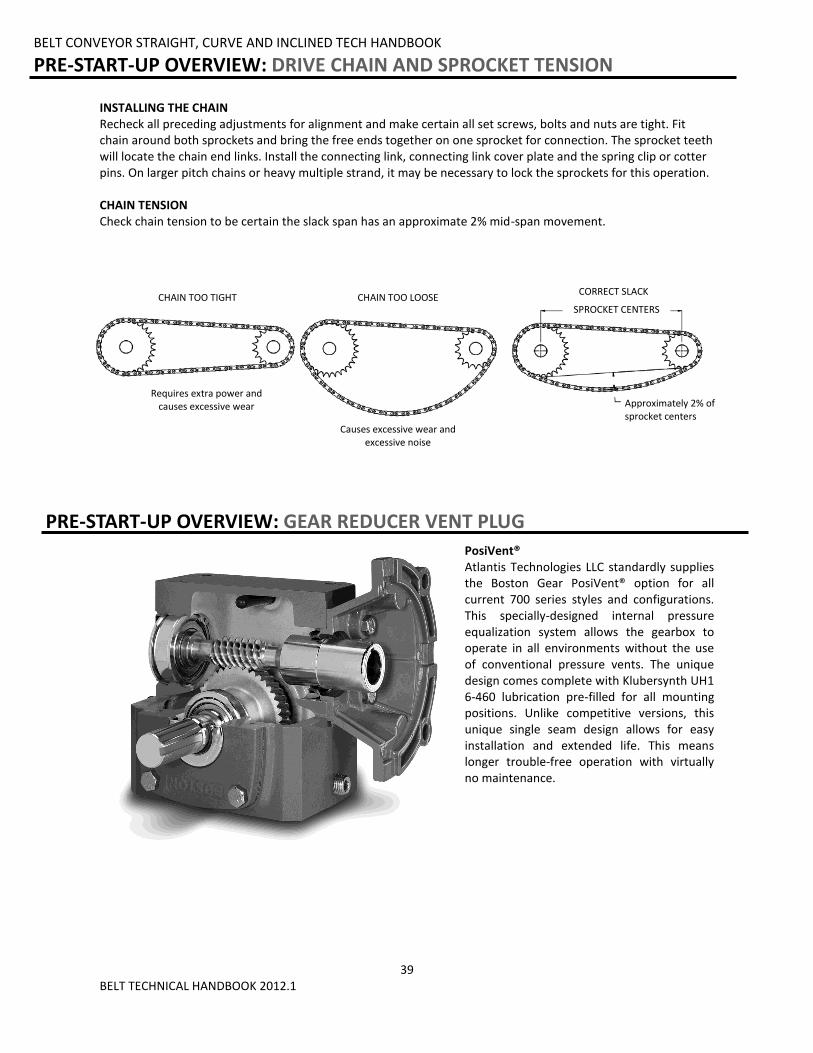
PosiVent® Atlantis Technologies LLC standardly supplies the Boston Gear PosiVent® option for all current 700 series styles and configurations. This specially-designed internal pressure equalization system allows the gearbox to operate in all environments without the use of conventional pressure vents. The unique design comes complete with Klubersynth UH1 6-460 lubrication pre-filled for all mounting positions. Unlike competitive versions, this unique single seam design allows for easy installation and extended life. This means longer trouble-free operation with virtually no maintenance.
INSTALLING THE CHAIN Recheck all preceding adjustments for alignment and make certain all set screws, bolts and nuts are tight. Fit chain around both sprockets and bring the free ends together on one sprocket for connection. The sprocket teeth will locate the chain end links. Install the connecting link, connecting link cover plate and the spring clip or cotter pins. On larger pitch chains or heavy multiple strand, it may be necessary to lock the sprockets for this operation. CHAIN TENSION Check chain tension to be certain the slack span has an approximate 2% mid-span movement.
CHAIN TOO TIGHT CHAIN TOO LOOSE SPROCKET CENTERS
Requires extra power and causes excessive wear
Causes excessive wear and excessive noise
CORRECT SLACK
Approximately 2% of sprocket centers
40 BELT TECHNICAL HANDBOOK 2012.1
BELT CONVEYOR STRAIGHT, CURVE AND INCLINED TECH HANDBOOK
MAINTENANCE: INSPECTION AND LUBRICATION
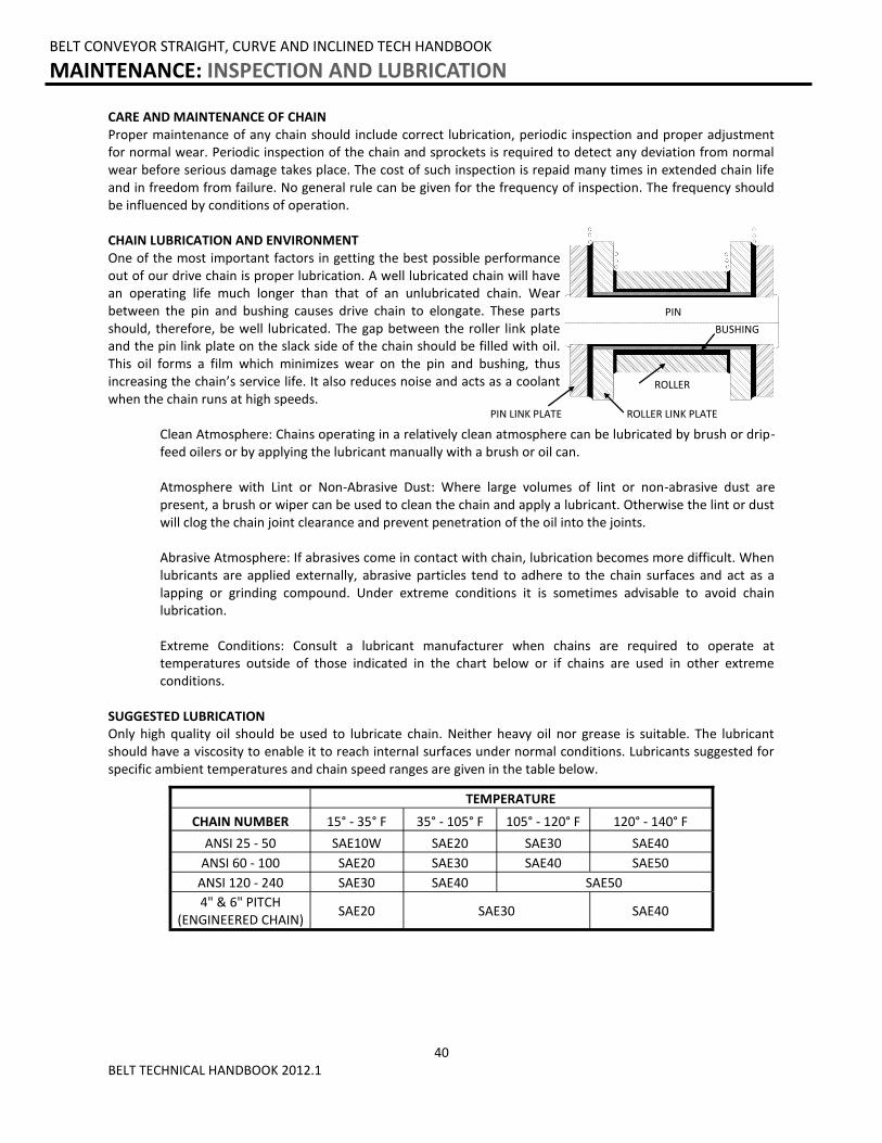
CARE AND MAINTENANCE OF CHAIN Proper maintenance of any chain should include correct lubrication, periodic inspection and proper adjustment for normal wear. Periodic inspection of the chain and sprockets is required to detect any deviation from normal wear before serious damage takes place. The cost of such inspection is repaid many times in extended chain life and in freedom from failure. No general rule can be given for the frequency of inspection. The frequency should be influenced by conditions of operation. CHAIN LUBRICATION AND ENVIRONMENT One of the most important factors in getting the best possible performance out of our drive chain is proper lubrication. A well lubricated chain will have an operating life much longer than that of an unlubricated chain. Wear between the pin and bushing causes drive chain to elongate. These parts should, therefore, be well lubricated. The gap between the roller link plate and the pin link plate on the slack side of the chain should be filled with oil. This oil forms a film which minimizes wear on the pin and bushing, thus increasing the chain’s service life. It also reduces noise and acts as a coolant when the chain runs at high speeds. Clean Atmosphere: Chains operating in a relatively clean atmosphere can be lubricated by brush or drip- feed oilers or by applying the lubricant manually with a brush or oil can. Atmosphere with Lint or Non-Abrasive Dust: Where large volumes of lint or non-abrasive dust are present, a brush or wiper can be used to clean the chain and apply a lubricant. Otherwise the lint or dust will clog the chain joint clearance and prevent penetration of the oil into the joints. Abrasive Atmosphere: If abrasives come in contact with chain, lubrication becomes more difficult. When lubricants are applied externally, abrasive particles tend to adhere to the chain surfaces and act as a lapping or grinding compound. Under extreme conditions it is sometimes advisable to avoid chain lubrication. Extreme Conditions: Consult a lubricant manufacturer when chains are required to operate at temperatures outside of those indicated in the chart below or if chains are used in other extreme conditions. SUGGESTED LUBRICATION Only high quality oil should be used to lubricate chain. Neither heavy oil nor grease is suitable. The lubricant should have a viscosity to enable it to reach internal surfaces under normal conditions. Lubricants suggested for specific ambient temperatures and chain speed ranges are given in the table below.
TEMPERATURE
CHAIN NUMBER 15° - 35° F 35° - 105° F 105° - 120° F 120° - 140° F
ANSI 25 - 50 SAE10W SAE20 SAE30 SAE40
ANSI 60 - 100 SAE20 SAE30 SAE40 SAE50
ANSI 120 - 240 SAE30 SAE40 SAE50
4" & 6" PITCH (ENGINEERED CHAIN)
SAE20 SAE30 SAE40
PIN
BUSHING
ROLLER
ROLLER LINK PLATE PIN LINK PLATE
41 BELT TECHNICAL HANDBOOK 2012.1
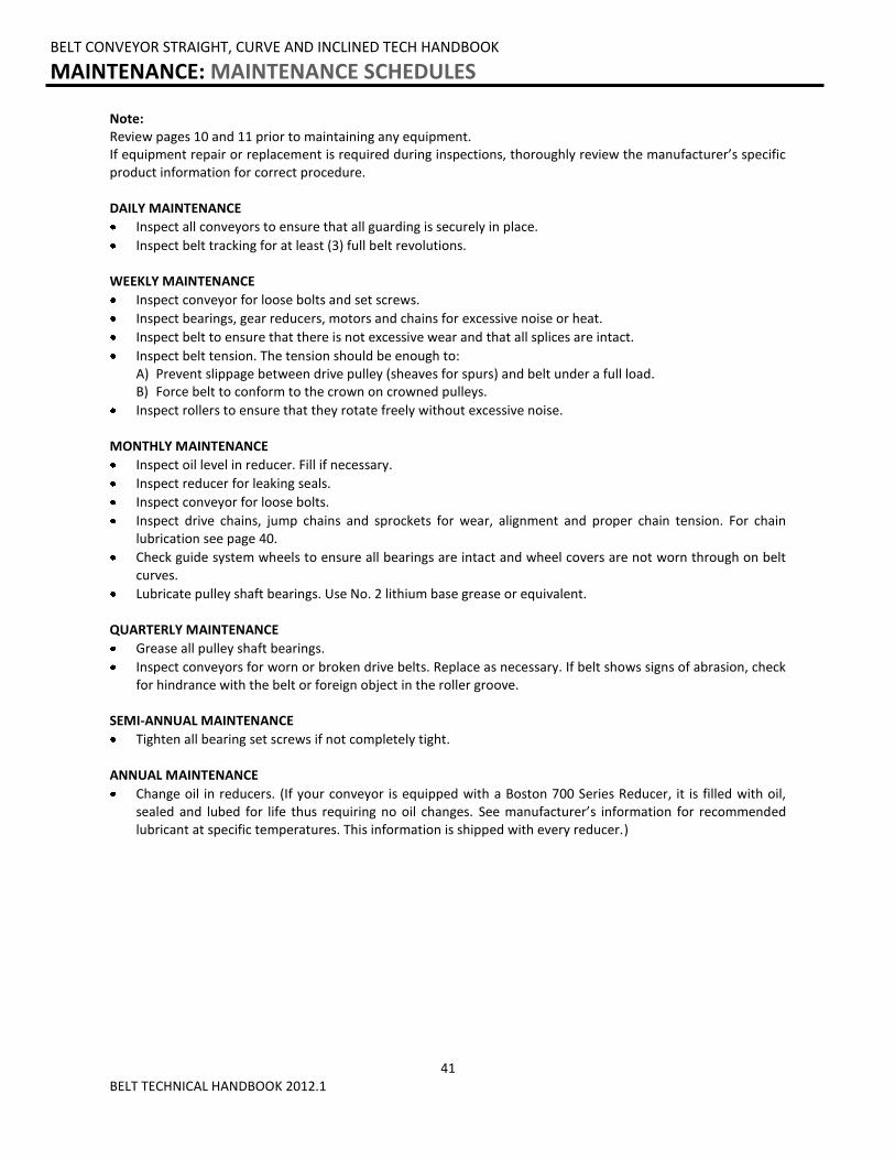
Note: Review pages 10 and 11 prior to maintaining any equipment. If equipment repair or replacement is required during inspections, thoroughly review the manufacturer’s specific product information for correct procedure. DAILY MAINTENANCE
Inspect all conveyors to ensure that all guarding is securely in place.
Inspect belt tracking for at least (3) full belt revolutions. WEEKLY MAINTENANCE
Inspect conveyor for loose bolts and set screws.
Inspect bearings, gear reducers, motors and chains for excessive noise or heat.
Inspect belt to ensure that there is not excessive wear and that all splices are intact.
Inspect belt tension. The tension should be enough to: A) Prevent slippage between drive pulley (sheaves for spurs) and belt under a full load. B) Force belt to conform to the crown on crowned pulleys.
Inspect rollers to ensure that they rotate freely without excessive noise. MONTHLY MAINTENANCE
Inspect oil level in reducer. Fill if necessary.
Inspect reducer for leaking seals.
Inspect conveyor for loose bolts.
Inspect drive chains, jump chains and sprockets for wear, alignment and proper chain tension. For chain lubrication see page 40.
Check guide system wheels to ensure all bearings are intact and wheel covers are not worn through on belt curves.
Lubricate pulley shaft bearings. Use No. 2 lithium base grease or equivalent. QUARTERLY MAINTENANCE
Grease all pulley shaft bearings.
Inspect conveyors for worn or broken drive belts. Replace as necessary. If belt shows signs of abrasion, check for hindrance with the belt or foreign object in the roller groove.
SEMI-ANNUAL MAINTENANCE
Tighten all bearing set screws if not completely tight. ANNUAL MAINTENANCE
Change oil in reducers. (If your conveyor is equipped with a Boston 700 Series Reducer, it is filled with oil, sealed and lubed for life thus requiring no oil changes. See manufacturer’s information for recommended lubricant at specific temperatures. This information is shipped with every reducer.)
BELT CONVEYOR STRAIGHT, CURVE AND INCLINED TECH HANDBOOK
MAINTENANCE: MAINTENANCE SCHEDULES

42 BELT TECHNICAL HANDBOOK 2012.1
REPORT ON MISCELLANEOUS MAINTENANCE PERFORMANCE Date___________ Maintenance Performed: ____________________________________________________________________________________________________________________________________________________________________________________________________________________________________________________________________________________ Date___________ Maintenance Performed: ____________________________________________________________________________________________________________________________________________________________________________________________________________________________________________________________________________________ Date___________ Maintenance Performed: ____________________________________________________________________________________________________________________________________________________________________________________________________________________________________________________________________________________ Date___________ Maintenance Performed: ____________________________________________________________________________________________________________________________________________________________________________________________________________________________________________________________________________________ Date___________ Maintenance Performed: ____________________________________________________________________________________________________________________________________________________________________________________________________________________________________________________________________________________ Date___________ Maintenance Performed: ____________________________________________________________________________________________________________________________________________________________________________________________________________________________________________________________________________________ Date___________ Maintenance Performed: ____________________________________________________________________________________________________________________________________________________________________________________________________________________________________________________________________________________
BELT CONVEYOR STRAIGHT, CURVE AND INCLINED TECH HANDBOOK
MAINTENANCE: REPORT ON MISCELLANEOUS MAINTENANCE PERFORMANCE

43 BELT TECHNICAL HANDBOOK 2012.1
BELT CONVEYOR STRAIGHT, CURVE AND INCLINED TECH HANDBOOK
TROUBLESHOOTING AND REPLACEMENT PARTS: TROUBLESHOOTING
TROUBLE CAUSE SOLUTION
Conveyor not starting or motor stalling
Motor is overloaded Check conveyor load. Remove excessive load.
Motor is drawing excessive current
Check circuit breaker
Excessive drive chain/sprocket wear
Inadequate lubrication Apply chain lubricant
Misaligned sprockets Align sprockets
Loose drive chain Tension drive chain
Loud popping or grinding noise
Faulty bearing Replace bearing
Loose drive sprocket set screw Tighten set screw and check key
Loose drive chain Tension drive chain
Motor and gear reducer makes excessive noise
Damaged gears Replace unit
Faulty bearing Replace bearing
Motor or reducer overheating
Conveyor overloaded Check conveyor load. Remove excessive load.
Low voltage to motor Correct voltage level
Reducer lubricant level low Fill reducer reservoir
Drive pulley turns but belt does not move or moves with a jerky motion
Conveyor overloaded Check conveyor load. Remove excessive load.
Loose conveyor belt Tighten conveyor belt
Belt installed upside down Install belt right side up
Belt slips and squeals Loose conveyor belt Tighten conveyor belt
Portion of belt creeps to one side
Belt ends not square Use T-Square to cut ends of belt squarely and re-install
Belt is bowed
Allow new belt to "break in"
If belt is "broke in", replace with a new belt
Excessive belt stretch Belt over tensioned Reduce belt tension. Check drive pulley for proper lagging.
Belt creeps to one side of head pulley
Head pulley or idlers preceding are out of alignment
Realign by advancing (adjust in the direction of belt travel) the end of the end of the pulley or idler to which the belt has shifted
Belt creeps to one side at one spot along the length of conveyor
One or more idlers preceding the trouble spot are out of alignment
Realign by advancing (adjust in the direction of belt travel) the end of the idler to which the belt has shifted
Improper loading of belt Center load on belt
Frozen idlers Replace idlers
Conveyor frame out of square or not level
Square and level conveyor frame
Debris build up on pulleys or idlers
Remove debris from pulleys or idlers
44 BELT TECHNICAL HANDBOOK 2012.1
BELT CONVEYOR STRAIGHT, CURVE AND INCLINED TECH HANDBOOK
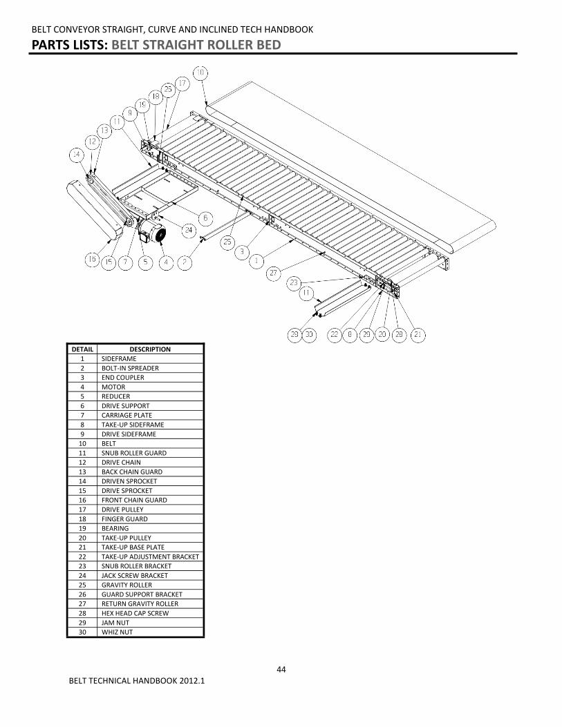
PARTS LISTS: BELT STRAIGHT ROLLER BED
DETAIL DESCRIPTION
1 SIDEFRAME
2 BOLT-IN SPREADER
3 END COUPLER
4 MOTOR
5 REDUCER
6 DRIVE SUPPORT
7 CARRIAGE PLATE
8 TAKE-UP SIDEFRAME
9 DRIVE SIDEFRAME
10 BELT
11 SNUB ROLLER GUARD
12 DRIVE CHAIN
13 BACK CHAIN GUARD
14 DRIVEN SPROCKET
15 DRIVE SPROCKET
16 FRONT CHAIN GUARD
17 DRIVE PULLEY
18 FINGER GUARD
19 BEARING
20 TAKE-UP PULLEY
21 TAKE-UP BASE PLATE
22 TAKE-UP ADJUSTMENT BRACKET
23 SNUB ROLLER BRACKET
24 JACK SCREW BRACKET
25 GRAVITY ROLLER
26 GUARD SUPPORT BRACKET
27 RETURN GRAVITY ROLLER
28 HEX HEAD CAP SCREW
29 JAM NUT
30 WHIZ NUT
45 BELT TECHNICAL HANDBOOK 2012.1
BELT CONVEYOR STRAIGHT, CURVE AND INCLINED TECH HANDBOOK
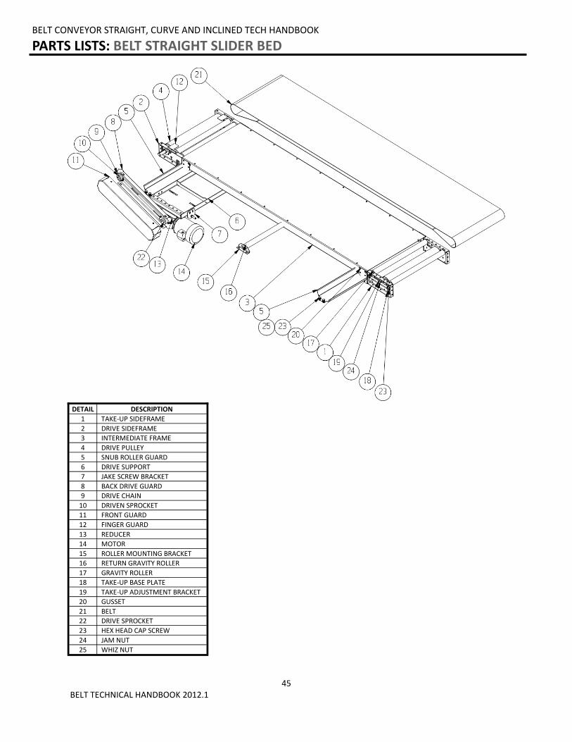
PARTS LISTS: BELT STRAIGHT SLIDER BED
DETAIL DESCRIPTION
1 TAKE-UP SIDEFRAME
2 DRIVE SIDEFRAME
3 INTERMEDIATE FRAME
4 DRIVE PULLEY
5 SNUB ROLLER GUARD
6 DRIVE SUPPORT
7 JAKE SCREW BRACKET
8 BACK DRIVE GUARD
9 DRIVE CHAIN
10 DRIVEN SPROCKET
11 FRONT GUARD
12 FINGER GUARD
13 REDUCER
14 MOTOR
15 ROLLER MOUNTING BRACKET
16 RETURN GRAVITY ROLLER
17 GRAVITY ROLLER
18 TAKE-UP BASE PLATE
19 TAKE-UP ADJUSTMENT BRACKET
20 GUSSET
21 BELT
22 DRIVE SPROCKET
23 HEX HEAD CAP SCREW
24 JAM NUT
25 WHIZ NUT
46 BELT TECHNICAL HANDBOOK 2012.1
BELT CONVEYOR STRAIGHT, CURVE AND INCLINED TECH HANDBOOK
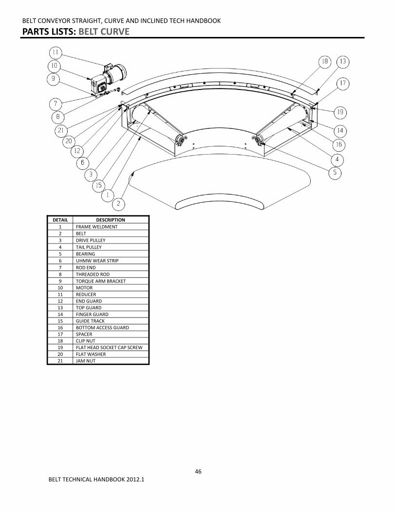
PARTS LISTS: BELT CURVE
DETAIL DESCRIPTION
1 FRAME WELDMENT
2 BELT
3 DRIVE PULLEY
4 TAIL PULLEY
5 BEARING
6 UHMW WEAR STRIP
7 ROD END
8 THREADED ROD
9 TORQUE ARM BRACKET
10 MOTOR
11 REDUCER
12 END GUARD
13 TOP GUARD
14 FINGER GUARD
15 GUIDE TRACK
16 BOTTOM ACCESS GUARD
17 SPACER
18 CLIP NUT
19 FLAT HEAD SOCKET CAP SCREW
20 FLAT WASHER
21 JAM NUT
47 BELT TECHNICAL HANDBOOK 2012.1
BELT CONVEYOR STRAIGHT, CURVE AND INCLINED TECH HANDBOOK
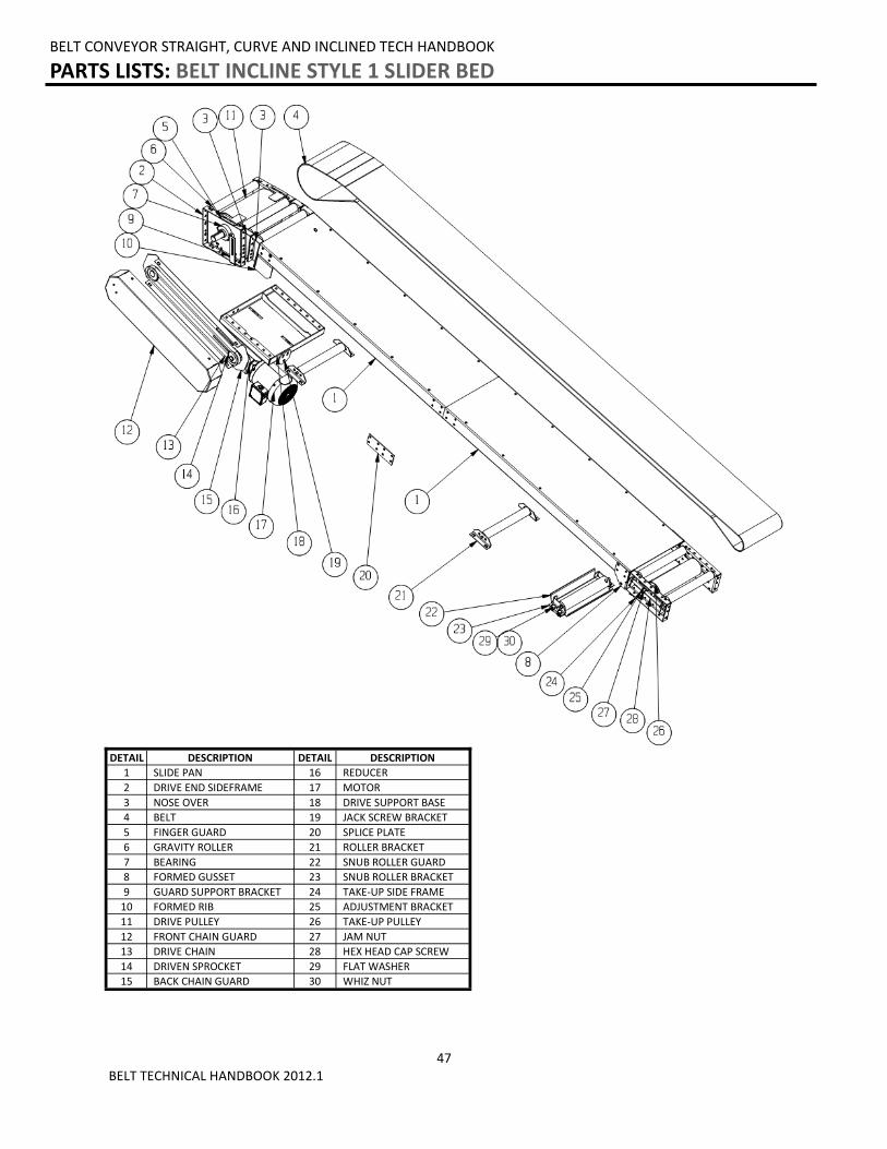
PARTS LISTS: BELT INCLINE STYLE 1 SLIDER BED
DETAIL DESCRIPTION DETAIL DESCRIPTION
1 SLIDE PAN 16 REDUCER
2 DRIVE END SIDEFRAME 17 MOTOR
3 NOSE OVER 18 DRIVE SUPPORT BASE
4 BELT 19 JACK SCREW BRACKET
5 FINGER GUARD 20 SPLICE PLATE
6 GRAVITY ROLLER 21 ROLLER BRACKET
7 BEARING 22 SNUB ROLLER GUARD
8 FORMED GUSSET 23 SNUB ROLLER BRACKET
9 GUARD SUPPORT BRACKET 24 TAKE-UP SIDE FRAME
10 FORMED RIB 25 ADJUSTMENT BRACKET
11 DRIVE PULLEY 26 TAKE-UP PULLEY
12 FRONT CHAIN GUARD 27 JAM NUT
13 DRIVE CHAIN 28 HEX HEAD CAP SCREW
14 DRIVEN SPROCKET 29 FLAT WASHER
15 BACK CHAIN GUARD 30 WHIZ NUT
48 BELT TECHNICAL HANDBOOK 2012.1
BELT CONVEYOR STRAIGHT, CURVE AND INCLINED TECH HANDBOOK
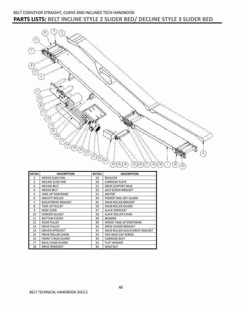
PARTS LISTS: BELT INCLINE STYLE 2 SLIDER BED/ DECLINE STYLE 3 SLIDER BED
DETAIL DESCRIPTION DETAIL DESCRIPTION
1 INFEED SLIDE PAN 19 REDUCER
2 INCLINE SLIDE PAN 20 CARRIAGE PLATE
3 INCLINE BELT 21 DRIVE SUPPORT BASE
4 INFEED BELT 22 JACK SCREW BRACKET
5 TAKE-UP SIDEFRAME 23 MOTOR
6 GRAVITY ROLLER 24 POWER TAKE-OFF GUARD
7 ADJUSTMENT BRACKET 25 SNUB ROLLER BRACKET
8 TAKE-UP PULLEY 26 SNUB ROLLER GUARD
9 NOSE OVER 27 SLAVE SPROCKET
10 FORMED GUSSET 28 SLAVE ROLLER CHIAN
11 BOTTOM COVER 29 BEARING
12 IDLER PULLEY 30 INFEED TAKE-UP SIDEFRAME
13 DRIVE PULLEY 31 DRIVE GUARD BRACKET
14 DRIVEN SPROCKET 32 SNUB ROLLER ADJUSTMENT BRACKET
15 DRIVE ROLLER CHAIN 33 HEX HEAD CAP SCREW
16 FRONT CHAIN GUARD 34 CARRIAGE BOLT
17 BACK CHAIN GUARD 35 FLAT WASHER
18 DRIVE SPROCKET 36 WHIZ NUT

49 BELT TECHNICAL HANDBOOK 2012.1
Notes:
________________________________________________________________________________________________________________________________________________________________________________________________________________________________________________________________________________________________________________________________________________________________________________________________________________________
____________________________________________________________________________________________________________________________________________________________________________________________________________________________________________________________________________________________________________________________________________________________________________________________________________________________________________________________________________________________________________________________________________________________________________________________________________________________________________________________________________________________________________________________________________________________________________________________________________________________________________________________________________________________________________________________________________________________________________________________________________________________________________________________________________________________________________________________________________________________________________________________________________________________________________________________________________________________________________________________________________________________________________________________________________________________________________________________________________________
BELT CONVEYOR STRAIGHT, CURVE AND INCLINED TECH HANDBOOK
NOTES
50 BELT TECHNICAL HANDBOOK 2012.1
BELT CONVEYOR STRAIGHT, CURVE AND INCLINED TECH HANDBOOK
ABBREVIATED WARRANTY
Atlantis Technologies LLC warrants that the Equipment will be free of defects in workmanship and material (if properly installed, operated and maintained) for a period of one year or 2080 hours of use, whichever is sooner, from date of shipment to Customer, subject to the limitations hereunder set forth. If within the one year warranty period, Atlantis receives from the Customer written notice of any alleged defects in the Equipment and if the Equipment is not found to be in conformity with this warranty (the Customer having provided Atlantis a reasonable opportunity to perform any appropriate tests thereon) Atlantis will, at its option, either repair the Equipment or supply a replacement therefore.
*The above stated information is in reference to a section of Atlantis Technologies’ full Terms and Conditions of sale. This information does not constitute an agreement, but simply reference information. To obtain a full copy of Atlantis Technologies’ Terms and Conditions of Sale, please contact your Sales Representative.

51 BELT TECHNICAL HANDBOOK 2012.1
Related Documents