Beamforming Algorithms for UWB Radar-based Stroke Detection: Trade-off Performance-Complexity E. Ricci, E. Cianca and T. Rossi Department of Electronic Engineering, University of Rome “Tor Vergata”, Rome, Italy E-mail: [email protected] Received 19 April 2016; Accepted 1 May 2016; Publication 21 May 2016 Abstract The use of UWB (Ultra-Wide Band) radar microwave imaging in stroke detec- tion opens the possibility to develop low cost, fast response and transportable diagnostic devices, which could play a key role in emergency scenarios. The feasibility of such a device is strictly related to the trade-off performance- complexity, which depends from the chosen beamforming algorithm, the number of antennas and the radar mode (monostatic/multistatic). This paper aims to provide a better understanding of this trade-off for several beam- forming algorithms and radar configurations (monostatic/multistatic) applied to stroke detection. Comparisons are performed assuming an antenna system with a low number of antennas (namely 8) with respect to more commonly considered settings for this application (from 16 to 48 antennas). The study is based on FDTD simulations and considered beamforming algorithms are: Delay & Sum (considered in most of the works on UWB radar stroke detection); MIST algorithms and adapted versions of the MIST and RAR algorithms originally proposed for breast cancer detection. Keywords: Brain stroke detection, beamforming algorithms, microwave UWB radar. Journal of Communication, Navigation, Sensing and Services, Vol. 1, 11–28. doi: 10.13052/jconasense2246-2120.2016.002 c 2016 River Publishers. All rights reserved.

Welcome message from author
This document is posted to help you gain knowledge. Please leave a comment to let me know what you think about it! Share it to your friends and learn new things together.
Transcript
Beamforming Algorithms for UWBRadar-based Stroke Detection:
Trade-off Performance-Complexity
E. Ricci, E. Cianca and T. Rossi
Department of Electronic Engineering, University of Rome “Tor Vergata”,Rome, ItalyE-mail: [email protected]
Received 19 April 2016; Accepted 1 May 2016;Publication 21 May 2016
Abstract
The use of UWB (Ultra-Wide Band) radar microwave imaging in stroke detec-tion opens the possibility to develop low cost, fast response and transportablediagnostic devices, which could play a key role in emergency scenarios. Thefeasibility of such a device is strictly related to the trade-off performance-complexity, which depends from the chosen beamforming algorithm, thenumber of antennas and the radar mode (monostatic/multistatic). This paperaims to provide a better understanding of this trade-off for several beam-forming algorithms and radar configurations (monostatic/multistatic) appliedto stroke detection. Comparisons are performed assuming an antenna systemwith a low number of antennas (namely 8) with respect to more commonlyconsidered settings for this application (from 16 to 48 antennas). The study isbased on FDTD simulations and considered beamforming algorithms are:Delay & Sum (considered in most of the works on UWB radar strokedetection); MIST algorithms and adapted versions of the MIST and RARalgorithms originally proposed for breast cancer detection.
Keywords: Brain stroke detection, beamforming algorithms, microwaveUWB radar.
Journal of Communication, Navigation, Sensing and Services, Vol. 1, 11–28.doi: 10.13052/jconasense2246-2120.2016.002c© 2016 River Publishers. All rights reserved.
12 E. Ricci et al.
1 Introduction
Microwave Imaging (MWI) is an emerging diagnostic branch based on theobservation that microwaves penetrate biological tissues and are reflected bydiscontinuities in the dielectric properties of the crossed tissues. Differenttissues, or the same tissue but in different functional condition (i.e. cancerousand healthy tissue) have different dielectric properties in the microwaveband. Two types of active microwave imaging techniques exist: tomographyimaging, that uses the scattered signals to reconstruct the profile of thedielectric properties of the tissues; UWB radar imaging, whose objective is toidentify the presence and location of significant backscattered energy arisingfrom the dielectric discontinuities between two different types of tissues. Thispaper is focused on UWB radar imaging.
Much works can be found on UWB radar imaging for breast cancerdetection [1–5], MWI has been also recently applied to brain imaging[6–9]. For both applications, the main pro offered by MWI lies in a non-ionizing, non-invasive screening technology that may help in reducing thenumber of false positives and false negatives [2]. However, in case of brainimaging, MWI offers the further advantage of allowing the design of a low cost,transportable and fast-response device that could efficiently complement thetraditional high-resolution imaging systems, such as CT (Computed Tomog-raphy) and MRI (Magnetic Resonance Imaging), in emergency scenarios. Asfor the heart attack, stroke patients should be dispatched at the highest levelof care available in the shortest time possible. In this context a transportablesystem, able to evaluate the presence of an acute brain lesion, can be placedin specialized ambulances, to perform a fast diagnosis and shorten the delayof treatment. In particular, the identification of a haemorrhagic nature of theevent could help to differentiate the subgroup of “haemorrhagic” patients from“possible ischemic” patients to select the most adequate hospital destinations.Therefore, in case of brain imaging, besides the potential to reduce the falsepositives and false negatives, it is important to keep low size, cost and theresponse time of the diagnostic device, which are related to the computationalcomplexity of the performed signal processing. The latter is based on twomain steps: a backscattered signals artifacts removal phase and a beamformingalgorithm.
As a matter of fact, most of the works in UWB radar for stroke detectionare based on a monostatic system and the Delay & Sum (DAS) beamformingalgorithm [8, 9], which is characterized by low computational complexity butalso limited robustness to artifacts. To achieve good performance, a very high
Beamforming Algorithms for UWB Radar-based Stroke Detection 13
number of antennas must be used (e.g. 16 and 32 in [9]). To improve theperformance and reduce the number of antennas, two different approaches arepossible:
• Optimizing the artifact removal phase [10, 11];• Using more complex beamforming algorithms [2, 3].
This paper aims to provide a better understanding of the trade-off performance-computational complexity of different beamforming algorithms applied toUWB radar stroke detection. We consider the following algorithms:
• Delay & Sum;• Microwave Imaging Space-Time (MIST) [2, 3] algorithm, which was
originally proposed for breast cancer detection;• a modified version of the Robust andArtifacts Resistant (RAR) algorithm
proposed in [12] for stroke detection.
In this paper, those algorithms are compared considering different perfor-mance metrics, taking also into account the computational complexity, bothin a monostatic and multistatic mode.
2 Signal Processing
This section presents the processing carried out on the received signals toobtain an image of backscattered microwave energy.
In the monostatic mode each antenna transmits a broadband pulse andreceives the backscattered signals to be processed. In the multistatic modeeach antenna transmits a broadband pulse and all the antennas, including thetransmitter, receive the backscattered signals. However, not all signals carryuseful information. For example, the channels related to antennas that are not inline of sight, since the head is interposed between them, do not contain relevantinformation. On the other hand, channels related to adjacent antennas havevery high information content and must be used by the processing algorithms.
Let xji be the signal associated to the jith channel, in which the ith antennatransmits and the jth antenna receives. The monostatic signals are those withj = i. Considering N antennas, the number of monostatic channel is C = N.The useful multistatic signals, that will be used for processing, are those withj = i ± 1, i.e. only the channels associated with adjacent antennas. ConsideringN antennas, the number of total multistatic channels is C = N * N and thenumber of useful multistatic channels is C = 2 * N. Hence, two groupsof channels are defined, the monostatic channels (j = i) and the selected
14 E. Ricci et al.
multistatic channels (j = i ± 1) with C = N + 2 * N channels, only thosesignals groups are the input of processing algorithms.
2.1 PLSR Artifact Removal
In this paper, the considered artifact removal is the PLSR (Partial Least SquareRegression) artifact removal algorithm proposed in [10]. In particular, theartifact on each channel is estimated as a linear combination of the artifactin all other channels, utilizing the maximization of correlation as constraintand relying on the assumption that the artifacts in all channels are similar, butnot identical. Finally, the estimate artifact is subtracted to the correspondingsignal and this procedure is repeated for each signal of each different channel.
Moreover, before passing the backscattered signals to the pre-processingalgorithm, a first cleaning of the signal is performed by a simple low passfilter [10], which helps to remove artifact components that are outside themain bandwidth extension of the stroke contribution.
2.2 Beamforming Algorithms
The goal of beamforming is spatial filtering, i.e. separation of signals thathave similar temporal frequency content but originate from different spatiallocations. The output of a beamformer is a weighted combination of the signalsreceived by each antenna. The beamformer is based on the principle of signalscoherent sum. The received signals are synthetically focused in a focal point oftissue through time shifts to approximately align them. The output is a map ofbackscattering energy in which each focal point is associated to the intensityof corresponding pixel in the energy map. If a strong scatterer exists at the focalpoint, i.e. the point represents a transition between tissues having differentdielectric properties, signals are summed coherently and the energy will berelatively high. On the other hand, if the focal point is homogeneous tissue,signals are summed incoherently and the energy level is low. All the focalpoints positions of the tissue to be examined are updating the time-shift phase.
2.2.1 Delay & Sum algorithmThe DAS is the simplest beamforming algorithm, widely used in brainapplication in monostatic mode [8, 9]. After the time-shift step, the alignedsignals are summed for each time sample n and focal point r0, as in (1):
z[n, r0] =C∑
i=1
xi[n − delay(r0)] =C∑
i=1
xi[n − (na − τi(r0))] (1)

Beamforming Algorithms for UWB Radar-based Stroke Detection 15
where C is the number of channels, xi is the backscattered signals of the ith
channel, na is the reference time to which all received signals are aligned andτ i(r0) is the roundtrip propagation delay for location r0 in the ithchannel.
Finally, the energy output of the focal point is computed as the sum ofsquared samples within a window h, as described in (2):
P [r0] =∑
n
|z[n, r0]h[n, r0]|2 (2)
The DAS algorithm has some drawbacks and requires further improvements.The main problem is the coarse time alignment, due to the phenomenon ofspreading, i.e. temporal enlargement of the transmitted pulse and consequentenergy dispersion. Moreover, the DAS provides limited capability to discrim-inate against clutter. On the other hand, the DAS has very low computationalcomplexity; this is a desirable characteristic in the design of a low-cost andfast-response device.
2.2.2 Microwave imaging space-time algorithmThe MIST algorithm was proposed for breast cancer application based onmonostatic radar in [2] and then optimized for multistatic approach in[3]. In [13], MIST algorithm has been modified and optimized for strokedetection.
After the time-shift step, the time aligned signals are passed through abank of FIR (Finite Impulse Response) filters, in order to provide amplitudeequalization and a finer alignment compared to the previous phase. A detaileddescription of the MIST algorithm used in our application can be foundin [13].
The output z is calculated for each time sample n and focal point r0 as:
z[n, r0] =C∑
i=1
L−1∑
l=0
wixi[n − l − (na − τi(r0))] (3)
where C is the number of channels, xi is the backscattered signals of the ith
channel, na is the reference time to which all received signals are aligned andτ i(r0) is the roundtrip propagation delay for location r0 in the ith channel, L isthe filters length and wi is the filter coefficients in the ith channel. The energyoutput of the focal point is computed as in (2).
The MIST has the not negligible disadvantage of a high computationalcomplexity, due to the introduction of the FIR filters.
16 E. Ricci et al.
2.2.3 Robust and artifact resistantThe RAR (Robust and Artifact Resistant) was proposed in [5] for breastcancer detection based on monostatic radar. A modification (Modified RAR)was proposed in [12] for head stroke detection both for monostatic andmultistatic radar. The algorithm is a modified version of the DAS in which aweighting factor is introduced for each focal point, in order to compensate thedrawbacks of the DAS without significantly increasing of the computationalcomplexity.
The first two steps are the signals time alignment and the signals summa-tion, as in (1). Then, an adaptive weight factor is introduced, by multiplyingPearson’s correlation coefficient of neighbouring pairwise transmitting-receiving antennas and selecting the M higher values. Let i be the numberof useful channel, the weight factor is calculated as follows:
wf [r0] =M∏
i=1
ci[r0] (4)
where M is the number of relevant correlation coefficients and ci is the cor-relation coefficient associated to the ith channel. A more detailed descriptionof the proposed Modified RAR algorithm can be found in [12].
The correlation coefficients are particularly useful as a measure of signalssimilarity. Based on the assumption that the signals are delayed version of thetransmitted pulse, a high correlation is expected at the same scatterer location.
In the modified RAR proposed in [12], and considered here, the numberof correlation coefficients used for the weighting factor is an arbitrary valueM chosen on the basis on MWI system features (number of antennas anddistance between them), the pre-processing algorithm used (the less effectiveis the pre-processing algorithm, the higher is the number M of coefficientsrequired to reduce the residual artifacts) and the trade-off between performanceand complexity (increasing M, the performance but also the complexityincreases).Alow number of the selected correlation coefficients would involvea worst discrimination between stroke and other scatterers, increasing the falsepositives. Whereas, a high number of the selected correlation coefficientswould lead to information loss. The M value used in this paper is C formonostatic mode and C/3 for multistatic mode, where C is the number ofuseful channels.
Finally the energy of the r0 focal point is calculated as follows:
P [r0] =α∑
n=1
wf [r0]z[n, r0] (5)
Beamforming Algorithms for UWB Radar-based Stroke Detection 17
where n = 1, . . . α is the samples number, wf is the weight factor and z isthe output calculated as in (1). If a scatterer is in a focal point r0, most of thecorrelation coefficients have high value and wf(r0) will be high. Conversely, ifa focal point represents a residual artifact, most of the correlation coefficientshave low value. Thus, wf(r0) maintains a low weight factor associated with thecorresponding focal point, even in the presence of an abnormal high correlationcoefficient, which could lead to a high intensity energy value.
The algorithm robustness is based on building an adaptive weighting factorfor each specific focal point.
3 Trade-off Performance-Complexity
3.1 System Model
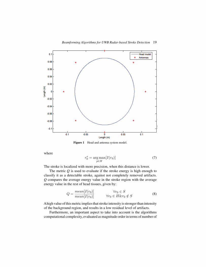
The diagnostic device is composed by an 8 UWB antenna array systemlocated around the head to be analyzed, arranged in an anatomical helmet-like structure. The number of antennas has been selected to limit the costsof the diagnostic device. The number of useful channel is C = 24. Eachantenna transmits an UWB pulse (Ricker pulse) into the tissues and collects thebackscattered signals, i.e. signals scattered from tissue discontinuities. Tworadar approaches are considered: monostatic and multistatic.
The transmitted pulse has a bandwidth that extends from 1 to 4 GHz, as aconsequence of a good trade-off between radar spatial resolution and wavesattenuation inside the human brain [14].
Backscattered signals have been generated using Finite-Difference Time-Domain (FDTD) software. The latter are then pre-processed to removeuseless information (artifacts). Then, the “cleaned” signals are processed bya beamforming algorithm, in order to build a map of backscattering energy ofthe head under examination. The antenna array assembly, the type of signaltransmitted by the antennas and the 3D head model are the input data of theFDTD software.
The head has been modelled as a 3D multi-layered structure (skin, bone,brain matter). The 3D model consists in a blended ellipsoid, simulating the realhead size [4]. In Cartesian coordinate system, the planar section of the modelhas semi axis along x of 80 mm and along y of 90 mm. The depth along z is100 mm. The head consists of a roughly 2 mm thick skin layer, a 6 mm thickbone layer and brain matter. Since biological tissues are dispersive medium,it is necessary to take the dispersive behaviour into account. The electricproperties have been evaluated according Cole-Cole model. In particular the
18 E. Ricci et al.
calculated parameters are fitted to a second-order polynomial. The dispersiveproprieties of the head tissues have been included in the FDTD model, settingdifferent dispersive electrical properties for skin, bone, brain matter andbleedings. Table 1 reports the main parameters of the different head tissuesconsidered in the model for the computation of the backscattered signals, atcenter frequency of 2.5 GHz [15].
Furthermore, we have also assumed the presence of a coupling medium,a mixture of different substance with dielectric constant similar to skin,between the antennas system and the head. This liquid increases electro-magnetic energy transmission inside the skull and reduces the reflectioncontribution.Also the coupling medium has been included in the FDTD model.
Figure 1 shows the planar section of the system model described, with aplanar section of the head as an ellipse and the antenna system as asterisks.
Noisy backscattered signals have been generated by adding whiteGaussian noise with a SNR of 10 dB. A spherical bleeding (haemorrhage)with a diameter of 20 mm, around 4 cc of blood, placed in different positionsof the head has been considered. Usually, the haemorrhages closer to the scalpare more difficult to localize as very close to the main source of artifacts.
3.2 Performance Metrics
Let us denote with I the obtained energy map, S the set of points that forma 2-D window around the detected target in the head, and H the set of allpoints within the head area, the following metrics have been used to comparedifferent beamforming algorithms.
The absolute distance Δ between the actual location of stroke χ and thelocation of the stroke predicted by the estimated maximum energy value in thebackscattering energy map I is a measure of the effectiveness of the proposedsystem in locating the stroke.
Δ = ‖r∗0 − χ‖ (6)
Table 1 Head properties at 2.5 GHz [15]Tissue Dielectric Constant Loss Tangent Conductivity (S/m)Skin 37.952 0.28184 1.4876Bone 11.352 0.25597 0.40411Brain matter 36.107 0.24699 0.24699Blood 58.181 0.31981 2.5878
Beamforming Algorithms for UWB Radar-based Stroke Detection 19
Figure 1 Head and antenna system model.
wherer∗0 = arg max
p∈H[I(r0)] (7)
The stroke is localized with more precision, when this distance is lower.The metric Q is used to evaluate if the stroke energy is high enough to
classify it as a detectable stroke, against not completely removed artifacts.Q compares the average energy value in the stroke region with the averageenergy value in the rest of head tissues, given by:
Q =mean[I(r0)]mean[I(r0)]
∀r0 ∈ S∀r0 ∈ H&r0 /∈ S
(8)
Ahigh value of this metric implies that stroke intensity is stronger than intensityof the background region, and results in a low residual level of artifacts.
Furthermore, an important aspect to take into account is the algorithmscomputational complexity, evaluated as magnitude order in terms of number of
20 E. Ricci et al.
basic mathematic operations (sums and products), as function of the algorithmsfree parameters. Low computational complexity is a key design driver for thisapplication, as it has an impact both on the response time of the device andon the cost.
3.3 Comparative Results
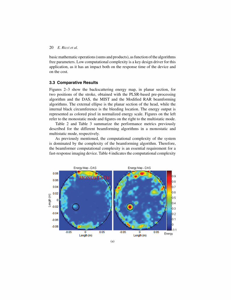
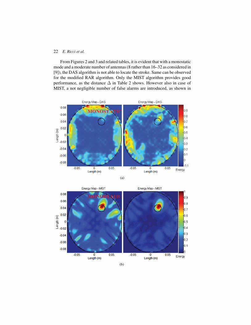
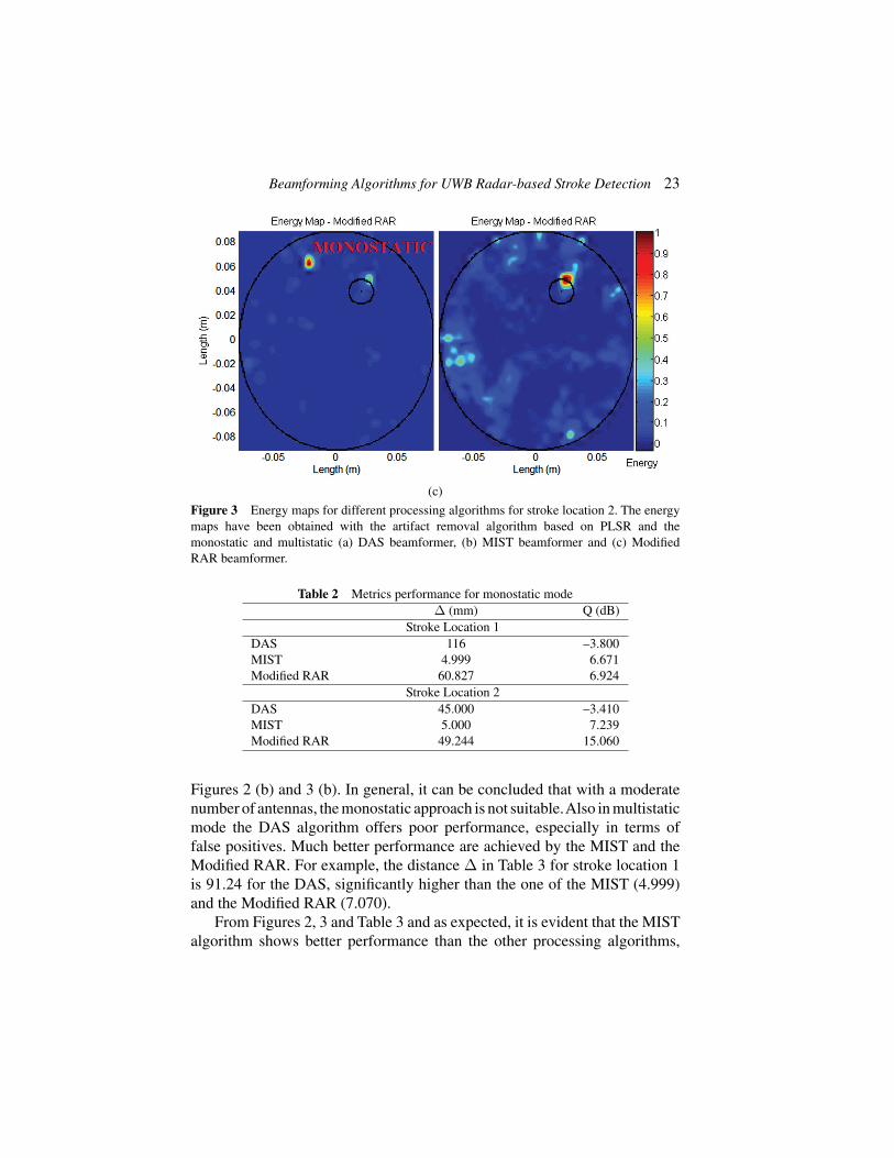
Figures 2–3 show the backscattering energy map, in planar section, fortwo positions of the stroke, obtained with the PLSR-based pre-processingalgorithm and the DAS, the MIST and the Modified RAR beamformingalgorithms. The external ellipse is the planar section of the head, while theinternal black circumference is the bleeding location. The energy output isrepresented as colored pixel in normalized energy scale. Figures on the leftrefer to the monostatic mode and figures on the right to the multistatic mode.
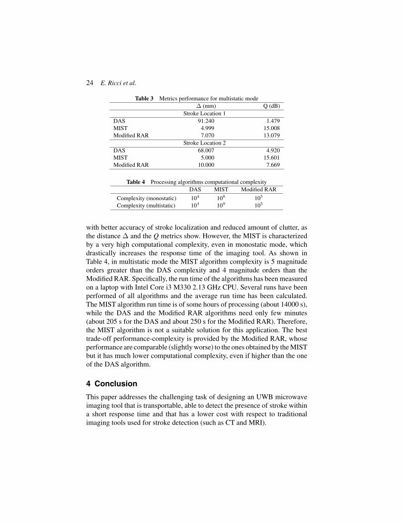
Table 2 and Table 3 summarize the performance metrics previouslydescribed for the different beamforming algorithms in a monostatic andmultistatic mode, respectively.
As previously mentioned, the computational complexity of the systemis dominated by the complexity of the beamforming algorithm. Therefore,the beamformer computational complexity is an essential requirement for afast-response imaging device. Table 4 indicates the computational complexity
(a)

Beamforming Algorithms for UWB Radar-based Stroke Detection 21
(b)
(c)
Figure 2 Energy maps for different processing algorithms for stroke location 1. The energymaps have been obtained with the artifact removal algorithm based on PLSR and themonostatic and multistatic (a) DAS beamformer, (b) MIST beamformer and (c) ModifiedRAR beamformer.
of the DAS, MIST and Modified RAR algorithms, in monostatic and multi-static mode, for each pixel of the energy map, evaluated in terms of numberof basic mathematical operations, in magnitude order, as function of the algo-rithms free parameters (channels number, sample number, FIR filters length).
22 E. Ricci et al.
From Figures 2 and 3 and related tables, it is evident that with a monostaticmode and a moderate number of antennas (8 rather than 16–32 as considered in[9]), the DAS algorithm is not able to locate the stroke. Same can be observedfor the modified RAR algorithm. Only the MIST algorithm provides goodperformance, as the distance Δ in Table 2 shows. However also in case ofMIST, a not negligible number of false alarms are introduced, as shown in
(a)
(b)
Beamforming Algorithms for UWB Radar-based Stroke Detection 23
(c)
Figure 3 Energy maps for different processing algorithms for stroke location 2. The energymaps have been obtained with the artifact removal algorithm based on PLSR and themonostatic and multistatic (a) DAS beamformer, (b) MIST beamformer and (c) ModifiedRAR beamformer.
Table 2 Metrics performance for monostatic modeΔ (mm) Q (dB)
Stroke Location 1DAS 116 –3.800MIST 4.999 6.671Modified RAR 60.827 6.924
Stroke Location 2DAS 45.000 –3.410MIST 5.000 7.239Modified RAR 49.244 15.060
Figures 2 (b) and 3 (b). In general, it can be concluded that with a moderatenumber of antennas, the monostatic approach is not suitable.Also in multistaticmode the DAS algorithm offers poor performance, especially in terms offalse positives. Much better performance are achieved by the MIST and theModified RAR. For example, the distance Δ in Table 3 for stroke location 1is 91.24 for the DAS, significantly higher than the one of the MIST (4.999)and the Modified RAR (7.070).
From Figures 2, 3 and Table 3 and as expected, it is evident that the MISTalgorithm shows better performance than the other processing algorithms,
24 E. Ricci et al.
Table 3 Metrics performance for multistatic modeΔ (mm) Q (dB)
Stroke Location 1DAS 91.240 1.479MIST 4.999 15.008Modified RAR 7.070 13.079
Stroke Location 2DAS 68.007 4.920MIST 5.000 15.601Modified RAR 10.000 7.669
Table 4 Processing algorithms computational complexityDAS MIST Modified RAR
Complexity (monostatic) 104 108 105
Complexity (multistatic) 104 109 105
with better accuracy of stroke localization and reduced amount of clutter, asthe distance Δ and the Q metrics show. However, the MIST is characterizedby a very high computational complexity, even in monostatic mode, whichdrastically increases the response time of the imaging tool. As shown inTable 4, in multistatic mode the MIST algorithm complexity is 5 magnitudeorders greater than the DAS complexity and 4 magnitude orders than theModified RAR. Specifically, the run time of the algorithms has been measuredon a laptop with Intel Core i3 M330 2.13 GHz CPU. Several runs have beenperformed of all algorithms and the average run time has been calculated.The MIST algorithm run time is of some hours of processing (about 14000 s),while the DAS and the Modified RAR algorithms need only few minutes(about 205 s for the DAS and about 250 s for the Modified RAR). Therefore,the MIST algorithm is not a suitable solution for this application. The besttrade-off performance-complexity is provided by the Modified RAR, whoseperformance are comparable (slightly worse) to the ones obtained by the MISTbut it has much lower computational complexity, even if higher than the oneof the DAS algorithm.
4 Conclusion
This paper addresses the challenging task of designing an UWB microwaveimaging tool that is transportable, able to detect the presence of stroke withina short response time and that has a lower cost with respect to traditionalimaging tools used for stroke detection (such as CT and MRI).
Beamforming Algorithms for UWB Radar-based Stroke Detection 25
Different beamforming algorithms (DAS, MIST and Modified RAR) havebeen compared in terms of different performance metrics and also computa-tional complexity, both in monostatic and multistatic mode. Moreover, in theconsidered comparison, the number of antennas has been kept lower than inother literature works as it also contribute to the size/weight and cost of thedevice. Performance evaluation has considered the presence of noise.
First of all, when the number of antennas is low, the monostatic approachis not able to guarantee good performance, regardless the beamforming algo-rithm. A multistatic approach provides much better performance at expense ofan increased computational complexity. This increase in computational com-plexity makes the MIST algorithm not feasible for this application. The besttrade-off performance-complexity is provided by the modified RAR algorithmin a multistatic mode, which achieves performance that are comparable, or justslightly worse, with the ones of the MIST. This is an important result towardthe implementation of a low cost and fast-response device, which is the maindriver for the use of a MWI approach in stroke detection.
References
[1] Li, X., Hagness, S. (2001). Confocal microwave imaging algorithm forbreast cancer detection. IEEE Microw. Compon. Lett. 11, 130–132.
[2] Bond, E., Li, X., Hagness, S., Van Veen, B. (2003). Microwave imagingvia space-time beamforming for early detection of breast cancer. IEEETrans. Antennas Propag. 51, 1690–1750.
[3] O’Halloran, M., Jones, E., Glavin, M. (2010). Quasi-multistatic MISTbeamforming for the early detection of breast cancer. IEEE Trans.Biomed. Eng. 57, 830–840.
[4] Zhang, H., Flynn, B., Erdogan, A., Arslan, T. (2012). “Microwaveimaging for brain tumor detection using an UWB Vivaldi antenna array,”in Antenna Propagation Conference LAPC, Loughborough.
[5] Yin, T., Ali, F., Reyes-Aldasoro, C. (2015). A robust and artifact resistantalgorithm of ultrawideband imaging system for breast cancer detection.IEEE Trans. Biomed. Eng. 62, 1514–1525.
[6] Fhager, A., Persson, M. (2012). “Stroke detection and diagnosis witha microwave helmet,” in Proceeding of the 6th European ConferenceAntennas Propagation, EuCAP, 1796–1798,
[7] Persson, M., Fhager, A., Trefnà, H., Yinan, Y., McKelvey, T.,Pegenius, G. et al. (2014). Microwave-based stroke diagnosis makingglobal prehospital thrombolytic treatment possible. IEEE Trans. Biomed.Eng. 61, 2806–2817.

26 E. Ricci et al.
[8] Ireland, D., Bialkowski, M. (2011). Microwave head imaging for strokedetection. Progr. Electromagn. Res. 21, 163–175.
[9] Mohammed, B. J., Abbosh, A., Mustafa, S., Ireland, D. (2014). Micro-wave system for head imaging. IEEE Trans. Instrum. Meas. 63, 117–123.
[10] Ricci, E., Di Domenico, S., Cianca, E., Rossi, T. (2015). “Artifact removalalgorithms for stroke detection using a multistatic MIST beamformingalgorithm,” in Proceeding of the 37th Annual International ConferenceEMBC, 1930–1933.
[11] Mustafa, S., Mohammed, B., Abbosh, A. (2013). Novel preprocessingtechniques for accurate microwave imaging of human brain. IEEEAntennas Wireless Propag. Lett. 12, 460–463.
[12] Ricci, E., Colucciello, A., di Domenico, S., Cianca, E., Rossi, T. (2015).“Modified RAR and PLSR-based artifact removal for stroke detection inUWB radar imaging,” in Proceeding of the 5th International ConferenceWireless Vitae, San Jose, CA.
[13] Ricci, E., Maggio, F., Rossi, T., Cianca, E., Ruggieri, M. (2015). “UWBradar imaging based on space-time beamforming for stroke detection,”in Proceeding of the 6th European Conference IFMBE, Dubrovnik, HR,946–949.
[14] Scapaticci, R., Di Donato, L., Crocco, L. (2012). A feasibility study onmicrowave imaging for brain stroke monitoring. Prog. Electromagn. Res.40, 305–324.
[15] Dielectric Properties of Body Tissues in the Frequency Range 10 Hz–100 GHz Available at: http://niremf.ifac.cnr.it/tissprop/
Biographies
E. Ricci received her M.Sc. degree in Medical Engineering in 2012 atUniversity of Rome Tor Vergata, where she is PhD student in the Departmentof Electronic Engineering. Her research is focused on medical imaging,biomedical signal processing, microwave imaging and UWB radar forbiomedical application.
Beamforming Algorithms for UWB Radar-based Stroke Detection 27
E. Cianca is assistant professor at the Department of Electronic Engineeringof the University of Rome Tor Vergata. Her research activity is focused onDSP and beamforming for radar and wireless communications.
T. Rossi isAssistant Professor at University of Rome Tor Vergata. His researchactivity is focused on space systems, DSP and beamforming for radar and TLCapplications.

Related Documents