VOL. 6, NO. 8, AUGUST 2011 ISSN 1819-6608 ARPN Journal of Engineering and Applied Sciences ©2006-2011 Asian Research Publishing Network (ARPN). All rights reserved. www.arpnjournals.com BEAM WIDTH ENHANCEMENT OF L1 AND L5 OF GLOBAL POSITIONING SYSTEM (GPS) ANTENNA Ahmed Al-Shaheen College of Medicine, Misan University, Maysan, Iraq E-Mail: [email protected] ABSTRACT In this paper we enhance the beam width for Global Positioning System (GPS) application rectangular patch microstrip antenna for two designs at L1 centered at 1.75742 GHz and L5 centered at 1.17642 GHz. Two antennas are mounted on the hexa-pyramidal ground plane to utilize for broadening the beam width for wide coverage area with circularly polarized radiation pattern, the antenna substrate is FR4 of ε r = 4.4 with thickness of 3.2 mm. The parametric study has been done to choose the optimum parameters for the top ground plane, base of ground plane, and drooped angle, the yielding results of this study shows that the beam width is up to 160 o and 170 o for E-plane and H-plane, respectively with a gain of -1.2 dB for RHCP radiation pattern at resonance frequency of 1.575 GHz antenna at top ground plane 40 mm and base ground plane 125 mm and 50 o for drooped angle. While, for the beam width is up to 150 o and 160 o for E- plane and H-plane respectively, with a gain of -1.67 dB for RHCP radiation pattern at resonance frequency of 1.176 GHz antenna at top ground plane 60 mm and base ground plane 150 mm and 60 o for drooped angle. The results are compared with the traditional rectangular patch microstrip antenna for the GPS application. The band width is 43 MHz and 54.7 MHz for to 1.57542 GHz and 1.17642, respectively. Keywords: GPS antenna, beam width enhancement, microstrip antenna, drooped ground plane. INTRODUCTION The application of the global positioning system GPS antenna on the land is differ from the application in the sea, it is more complicate, because the ship in the sea is moving according to the motion of the sea waves, and then the navigation of the ship becomes more difficult if the antenna is narrow beam width. An L band from 1.1 GHz to 1.6 GHz is fabricated and tested. The simulated and measured results show that the beam widths at lower frequencies are broadened and uniform radiation patterns over the whole operating frequency band are obtained [1]. A GPS textile wearable patch antenna was designed in order to meet such requirements. Performance investigations on a realized prototype were carried out by means of measurements in open space and in two real- work situations, showing an excellent behavior in open- space and a slight performance degradation when textiles and/or human body are present. However, the performance of the proposed antenna is sufficiently satisfactory and promising for application in wearable textile systems [2]. Circularly polarized patch antennas are widely used in some mobile satellite communications and most communication systems. A typical technique for producing circular polarization wave involves the use of feeding structure to excite two orthogonal linearly polarized modes of equal amplitude and a 90 o phase difference, coupling technique has been used in [3] in terms of to achieving circular polarized radiation by developing a square ring patch antenna feed by the strip line, The prototype has been designed, fabricated and found to have an impedance bandwidth of 1.1% and a 3- dB axial-ratio bandwidth of about 0.03% at GPS frequency of 1573 MHz. A new GPS microstrip patch antenna designed for dual-band (L1 and L2) operation is introduced. The antenna design is based on the reduced-surface-wave (RSW) concept. In [4], the radiation characteristics of this new design will be compared to a dual band choke-ring and a dual-band pinwheel antenna. This planar dual-band antenna lacks the design complications associated with the frequently-used stacked-patch method for realizing dual- band microstrip antenna performance. Thus, the simplicity of the design, together with the reduced horizon and backside radiation levels and excellent circular polarization characteristics indicate that this new antenna design is a promising candidate for dual-band, high- precision applications. A prototype of the pyramidal multiband antenna loaded with its cutoff and open-ended waveguide is simulated and fabricated to allow bringing closer the feeding ports of the antenna and consequently, obtaining quasi-omnidirectional radiation pattern at the operating frequencies. Folded and drooped microstrip antennas are investigated in this communication for their potential applications in GPS marine navigation. Numerical and experimental results are reported to identify the effects of the percentage of the patch extending around to the folded side, position, and angle of the bend on the performance of the proposed antennas in comparison to the conventional flat counterparts. The folded antennas provide marginally improved 3-dB beam width and excellent phase center stability without degrading the bore-sight gain. A novel drooped square annular element operating in the TM mode is proposed and validated both numerically and experimentally. The drooped annular antenna is shown to have substantially improved above-horizon coverage to suit applications requiring acquisition of satellites from horizon to horizon with a pattern ripple less than 2 dB over the upper hemisphere and with an impedance bandwidth of 2%. The polarization rejection is marginally degraded at 15

Welcome message from author
This document is posted to help you gain knowledge. Please leave a comment to let me know what you think about it! Share it to your friends and learn new things together.
Transcript

VOL. 6, NO. 8, AUGUST 2011 ISSN 1819-6608
ARPN Journal of Engineering and Applied Sciences
©2006-2011 Asian Research Publishing Network (ARPN). All rights reserved.
www.arpnjournals.com
BEAM WIDTH ENHANCEMENT OF L1 AND L5 OF GLOBAL
POSITIONING SYSTEM (GPS) ANTENNA
Ahmed Al-Shaheen College of Medicine, Misan University, Maysan, Iraq
E-Mail: [email protected] ABSTRACT
In this paper we enhance the beam width for Global Positioning System (GPS) application rectangular patch microstrip antenna for two designs at L1 centered at 1.75742 GHz and L5 centered at 1.17642 GHz. Two antennas are mounted on the hexa-pyramidal ground plane to utilize for broadening the beam width for wide coverage area with circularly polarized radiation pattern, the antenna substrate is FR4 of εr = 4.4 with thickness of 3.2 mm. The parametric study has been done to choose the optimum parameters for the top ground plane, base of ground plane, and drooped angle, the yielding results of this study shows that the beam width is up to 160o and 170o for E-plane and H-plane, respectively with a gain of -1.2 dB for RHCP radiation pattern at resonance frequency of 1.575 GHz antenna at top ground plane 40 mm and base ground plane 125 mm and 50o for drooped angle. While, for the beam width is up to 150o and 160o for E-plane and H-plane respectively, with a gain of -1.67 dB for RHCP radiation pattern at resonance frequency of 1.176 GHz antenna at top ground plane 60 mm and base ground plane 150 mm and 60o for drooped angle. The results are compared with the traditional rectangular patch microstrip antenna for the GPS application. The band width is 43 MHz and 54.7 MHz for to 1.57542 GHz and 1.17642, respectively. Keywords: GPS antenna, beam width enhancement, microstrip antenna, drooped ground plane. INTRODUCTION
The application of the global positioning system GPS antenna on the land is differ from the application in the sea, it is more complicate, because the ship in the sea is moving according to the motion of the sea waves, and then the navigation of the ship becomes more difficult if the antenna is narrow beam width. An L band from 1.1 GHz to 1.6 GHz is fabricated and tested. The simulated and measured results show that the beam widths at lower frequencies are broadened and uniform radiation patterns over the whole operating frequency band are obtained [1]. A GPS textile wearable patch antenna was designed in order to meet such requirements. Performance investigations on a realized prototype were carried out by means of measurements in open space and in two real-work situations, showing an excellent behavior in open-space and a slight performance degradation when textiles and/or human body are present. However, the performance of the proposed antenna is sufficiently satisfactory and promising for application in wearable textile systems [2].
Circularly polarized patch antennas are widely used in some mobile satellite communications and most communication systems. A typical technique for producing circular polarization wave involves the use of feeding structure to excite two orthogonal linearly polarized modes of equal amplitude and a 90o phase difference, coupling technique has been used in [3] in terms of to achieving circular polarized radiation by developing a square ring patch antenna feed by the strip line, The prototype has been designed, fabricated and found to have an impedance bandwidth of 1.1% and a 3-dB axial-ratio bandwidth of about 0.03% at GPS frequency of 1573 MHz.
A new GPS microstrip patch antenna designed for dual-band (L1 and L2) operation is introduced. The
antenna design is based on the reduced-surface-wave (RSW) concept. In [4], the radiation characteristics of this new design will be compared to a dual band choke-ring and a dual-band pinwheel antenna. This planar dual-band antenna lacks the design complications associated with the frequently-used stacked-patch method for realizing dual-band microstrip antenna performance. Thus, the simplicity of the design, together with the reduced horizon and backside radiation levels and excellent circular polarization characteristics indicate that this new antenna design is a promising candidate for dual-band, high-precision applications.
A prototype of the pyramidal multiband antenna loaded with its cutoff and open-ended waveguide is simulated and fabricated to allow bringing closer the feeding ports of the antenna and consequently, obtaining quasi-omnidirectional radiation pattern at the operating frequencies. Folded and drooped microstrip antennas are investigated in this communication for their potential applications in GPS marine navigation. Numerical and experimental results are reported to identify the effects of the percentage of the patch extending around to the folded side, position, and angle of the bend on the performance of the proposed antennas in comparison to the conventional flat counterparts. The folded antennas provide marginally improved 3-dB beam width and excellent phase center stability without degrading the bore-sight gain. A novel drooped square annular element operating in the TM mode is proposed and validated both numerically and experimentally. The drooped annular antenna is shown to have substantially improved above-horizon coverage to suit applications requiring acquisition of satellites from horizon to horizon with a pattern ripple less than 2 dB over the upper hemisphere and with an impedance bandwidth of 2%. The polarization rejection is marginally degraded at
15
VOL. 6, NO. 8, AUGUST 2011 ISSN 1819-6608
ARPN Journal of Engineering and Applied Sciences
©2006-2011 Asian Research Publishing Network (ARPN). All rights reserved.
www.arpnjournals.com
bore-sight. At the horizon, the cross component becomes dominant by 1.5 dB [6].
In this paper we enhance the beam width for wide coverage of GPS antenna in L1 with center resonant frequency of 1.57542 GHz and L5 with centered resonant frequency of 1.17642 GHz by utilizing from the mounted the antenna on the hexa-pyramidal ground plane with pyramid with variable height controlled by drooped angle α.
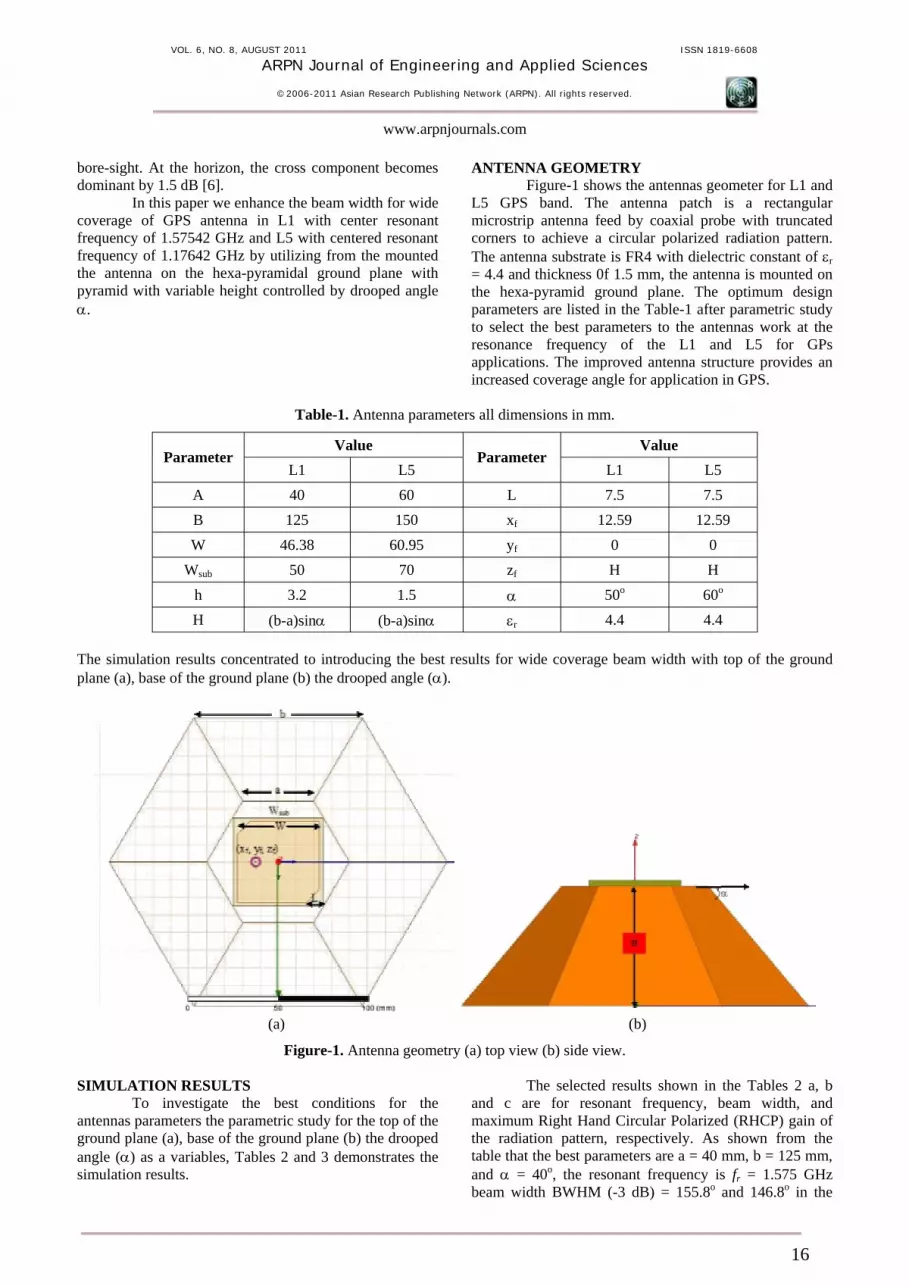
ANTENNA GEOMETRY Figure-1 shows the antennas geometer for L1 and
L5 GPS band. The antenna patch is a rectangular microstrip antenna feed by coaxial probe with truncated corners to achieve a circular polarized radiation pattern. The antenna substrate is FR4 with dielectric constant of εr = 4.4 and thickness 0f 1.5 mm, the antenna is mounted on the hexa-pyramid ground plane. The optimum design parameters are listed in the Table-1 after parametric study to select the best parameters to the antennas work at the resonance frequency of the L1 and L5 for GPs applications. The improved antenna structure provides an increased coverage angle for application in GPS.
Table-1. Antenna parameters all dimensions in mm.
Value Value Parameter
L1 L5 Parameter
L1 L5 A 40 60 L 7.5 7.5 B 125 150 xf 12.59 12.59 W 46.38 60.95 yf 0 0
Wsub 50 70 zf H H h 3.2 1.5 α 50o 60o
H (b-a)sinα (b-a)sinα εr 4.4 4.4 The simulation results concentrated to introducing the best results for wide coverage beam width with top of the ground plane (a), base of the ground plane (b) the drooped angle (α).
(a) (b)
Figure-1. Antenna geometry (a) top view (b) side view. SIMULATION RESULTS
To investigate the best conditions for the antennas parameters the parametric study for the top of the ground plane (a), base of the ground plane (b) the drooped angle (α) as a variables, Tables 2 and 3 demonstrates the simulation results.
The selected results shown in the Tables 2 a, b and c are for resonant frequency, beam width, and maximum Right Hand Circular Polarized (RHCP) gain of the radiation pattern, respectively. As shown from the table that the best parameters are a = 40 mm, b = 125 mm, and α = 40o, the resonant frequency is fr = 1.575 GHz beam width BWHM (-3 dB) = 155.8o and 146.8o in the
16
VOL. 6, NO. 8, AUGUST 2011 ISSN 1819-6608
ARPN Journal of Engineering and Applied Sciences
©2006-2011 Asian Research Publishing Network (ARPN). All rights reserved.
www.arpnjournals.com
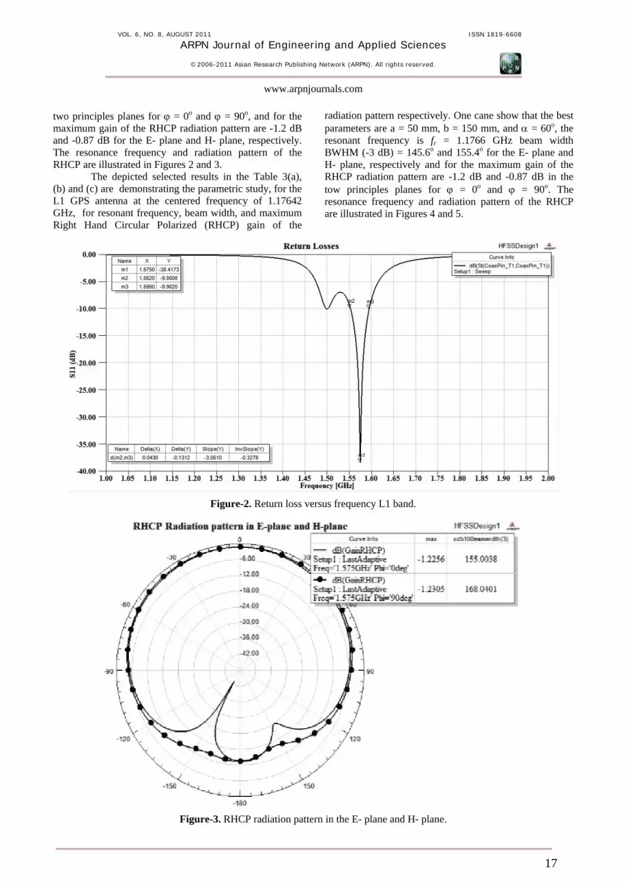
two principles planes for ϕ = 0o and ϕ = 90o, and for the maximum gain of the RHCP radiation pattern are -1.2 dB and -0.87 dB for the E- plane and H- plane, respectively. The resonance frequency and radiation pattern of the RHCP are illustrated in Figures 2 and 3.
The depicted selected results in the Table 3(a), (b) and (c) are demonstrating the parametric study, for the L1 GPS antenna at the centered frequency of 1.17642 GHz, for resonant frequency, beam width, and maximum Right Hand Circular Polarized (RHCP) gain of the
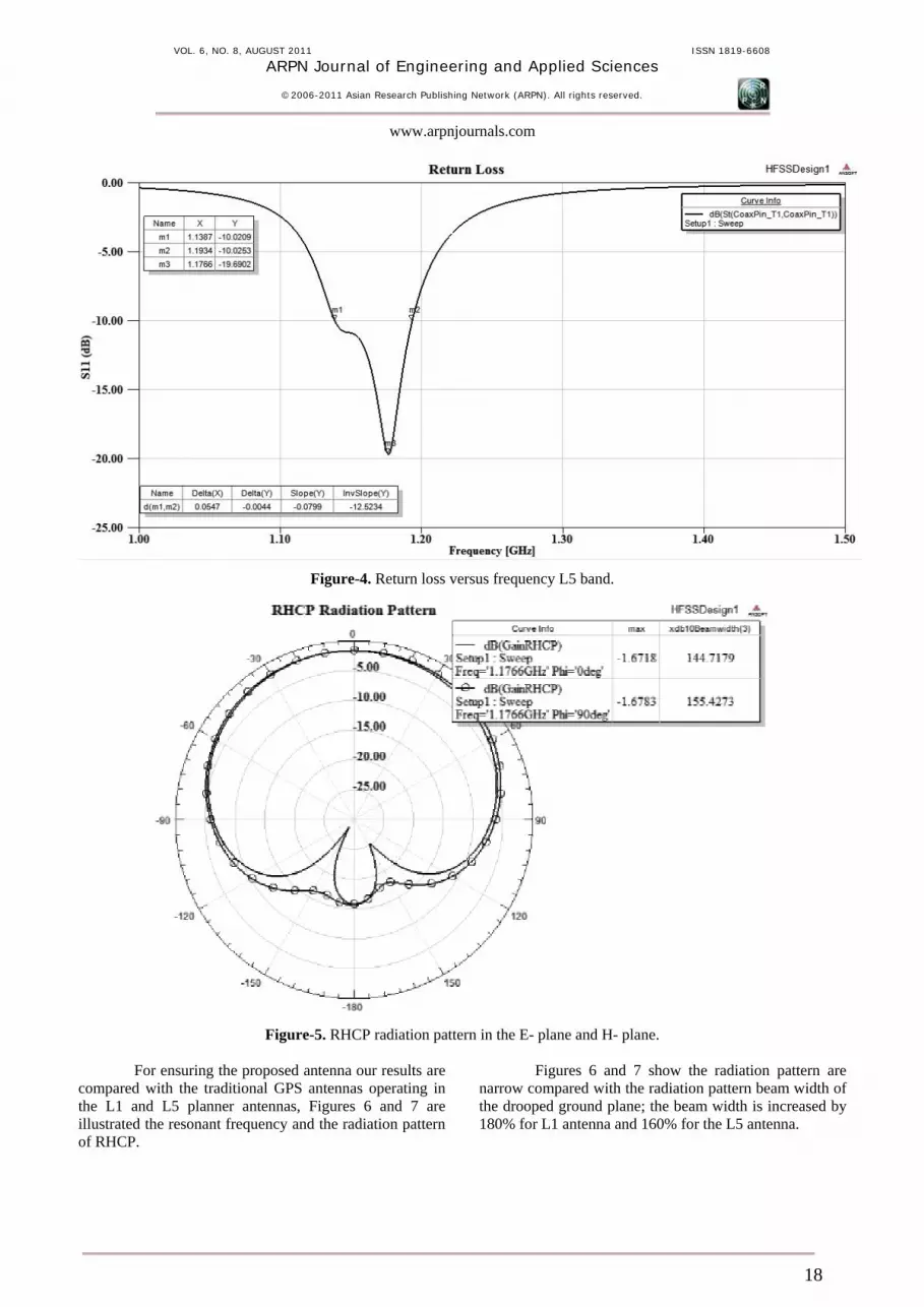
radiation pattern respectively. One cane show that the best parameters are a = 50 mm, b = 150 mm, and α = 60o, the resonant frequency is fr = 1.1766 GHz beam width BWHM (-3 dB) = 145.6o and 155.4o for the E- plane and H- plane, respectively and for the maximum gain of the RHCP radiation pattern are -1.2 dB and -0.87 dB in the tow principles planes for ϕ = 0o and ϕ = 90o. The resonance frequency and radiation pattern of the RHCP are illustrated in Figures 4 and 5.
Figure-2. Return loss versus frequency L1 band.
Figure-3. RHCP radiation pattern in the E- plane and H- plane.
17
VOL. 6, NO. 8, AUGUST 2011 ISSN 1819-6608
ARPN Journal of Engineering and Applied Sciences
©2006-2011 Asian Research Publishing Network (ARPN). All rights reserved.
www.arpnjournals.com
Figure-4. Return loss versus frequency L5 band.
Figure-5. RHCP radiation pattern in the E- plane and H- plane.
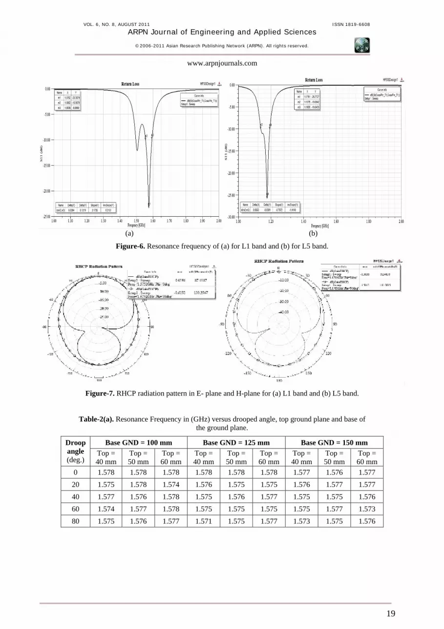
For ensuring the proposed antenna our results are compared with the traditional GPS antennas operating in the L1 and L5 planner antennas, Figures 6 and 7 are illustrated the resonant frequency and the radiation pattern of RHCP.
Figures 6 and 7 show the radiation pattern are narrow compared with the radiation pattern beam width of the drooped ground plane; the beam width is increased by 180% for L1 antenna and 160% for the L5 antenna.
18
VOL. 6, NO. 8, AUGUST 2011 ISSN 1819-6608
ARPN Journal of Engineering and Applied Sciences
©2006-2011 Asian Research Publishing Network (ARPN). All rights reserved.
www.arpnjournals.com
(a) (b)
Figure-6. Resonance frequency of (a) for L1 band and (b) for L5 band.
Figure-7. RHCP radiation pattern in E- plane and H-plane for (a) L1 band and (b) L5 band.
Table-2(a). Resonance Frequency in (GHz) versus drooped angle, top ground plane and base of the ground plane.
Base GND = 100 mm Base GND = 125 mm Base GND = 150 mm Droop angle (deg.)
Top = 40 mm
Top = 50 mm
Top = 60 mm
Top = 40 mm
Top = 50 mm
Top = 60 mm
Top = 40 mm
Top = 50 mm
Top = 60 mm
0 1.578 1.578 1.578 1.578 1.578 1.578 1.577 1.576 1.577 20 1.575 1.578 1.574 1.576 1.575 1.575 1.576 1.577 1.577 40 1.577 1.576 1.578 1.575 1.576 1.577 1.575 1.575 1.576 60 1.574 1.577 1.578 1.575 1.575 1.575 1.575 1.577 1.573 80 1.575 1.576 1.577 1.571 1.575 1.577 1.573 1.575 1.576
19
VOL. 6, NO. 8, AUGUST 2011 ISSN 1819-6608
ARPN Journal of Engineering and Applied Sciences
©2006-2011 Asian Research Publishing Network (ARPN). All rights reserved.
www.arpnjournals.com
Table-2(b). Beam width in (deg.) of the RHCP radiation pattern gain in the E-plane and H-plane versus drooped angle,
top ground plane and base of the ground plane.
Base GND = 100 mm Base GND = 125 mm Base GND = 150 mm
Top = 40 mm Top = 50 mm Top = 60 mm Top = 40 mm Top = 50 mm Top = 60 mm Top = 40 mm Top = 50 mm Top = 60 mm Droop angle (deg.) E-
plane H-
plane E-
plane H-
plane E-
plane H-
plane E-
plane H-
plane E-
plane H-
plane E-
plane H-
plane E-
plane H-
plane E-
plane H-
plane E-
plane H-
plane 0 80.7 67.8 82.7 67.8 80.7 67.8 81.2 62.8 81.2 62.8 81.2 62.8 92.8 69.1 92.8 69.1 92.8 69.1
20 95.7 79.3 93.8 76.9 90.7 75.6 118 98.5 113.9 95.2 107.3 88.4 131.7 119.4 129.4 117.6 124 111.5
40 124.6 111.2 115.2 98.5 105 88.5 156.8 146.8 143 136 130.2 119.8 107 130.8 105 125 108.8 118.5
60 150 141.7 128.3 119 111.6 101.3 134.5 166.2 139.5 98.5 111.7 120.8 72.12 77.6 73.2 78.8 75.8 82.9
80 140.2 141.3 122.7 122.3 110.1 104.2 93 156.7 91 120.2 93 105.3 80.6 83.1 80 79.9 78.7 78.4
Table-2(c). Maximum Gain in (dB) in the E-plane and H-plane versus drooped angle, top ground plane
and base of the ground plane.
Base GND = 100 mm Base GND = 125 mm Base GND = 150 mm Top = 40
mm Top = 50
mm Top = 60
mm Top = 40
mm Top = 50
mm Top = 60
mm Top = 40
mm Top = 50
mm Top = 60
mm Droop angle (deg.) E-
plane H-
plane E-
plane H-
plane E-
plane H-
plane E-
plane H-
plane E-
plane H-
plane E-
plane H-
plane E-
plane H-
plane E-
plane H-
plane E-
plane H-
plane 0 3.13 3.30 3.31 3.31 3.31 3.31 3.1 3.1 3.12 3.11 3.12 3.11 2.48 2.47 2.48 2.46 2.48 2.46
20 2.36 2.36 2.47 2.46 2.59 2.57 0.89 0.81 1.11 1.06 1.44 1.42 -0.03 0.15 0.05 0.125 0.41 0.46
40 0.58 0.57 1.09 1.09 1.84 1.82 -1.2 -0.87 -0.66 -0.58 1.19 1.19 0.3 0.35 0.49 0.49 0.73 0.73
60 -0.64 -0.65 0.41 0.41 1.30 1.29 -0.75 -0.75 -0.07 -0.07 0.57 0.57 1.61 1.61 1.69 1.68 2.06 2.06
80 -0.47 -0.47 0.50 0.49 1.34 1.34 -0.37 -0.37 0.54 0.54 1.16 1.16 1.29 1.29 1.96 1.96 2.29 2.29
Table-3(a). Resonance Frequency in (GHz) versus drooped angle, top ground plane and base of the ground plane.
Base GND = 100 mm Base GND = 125 mm Base GND = 150 mm Droop angle (deg.) Top = 55
mm Top = 60
mm Top = 65
mm Top = 55
mm Top = 60
mm Top = 65
mm Top = 55 mm Top = 60 mm
Top = 65 mm
0 1.1757 1.1757 1.1757 1.1777 1.1777 1.1777 1.1743 1.1743 1.1745
20 1.1761 1.1765 1.1748 1.1755 1.1765 1.1760 1.1752 1.1744 1.1772
40 1.1737 1.1742 1.1766 1.1751 1.1770 1.1761 1.1738 1.1759 1.1754
60 1.1737 1.1753 1.1761 1.1733 1.1747 1.1765 1.1746 1.1766 1.1737
80 1.1724 1.1747 1.1725 1.1741 1.1723 1.1736 1.1734 1.1746 1.1740
Table-3(b). Beam width in (deg.) of the RHCP radiation pattern gain in the E-plane and H-plane versus drooped angle,
top ground plane and base of the ground plane.
Base GND = 100 mm Base GND = 125 mm Base GND = 150 mm
Top = 55 mm Top = 60 mm Top = 65 mm Top = 55 mm Top = 60 mm Top = 65 mm Top = 55 mm Top = 60 mm Top = 65 mm Droop angle (deg.) E-
plane H-
plane E-
plane H-
plane E-
plane H-
plane E-
plane H-
plane E-
plane H-
plane E-
plane H-
plane E-
plane H-
plane E-
plane H-
plane E-
plane H-
plane 0 88.3 79.6 88.3 79.6 88.3 79.6 85 73.9 85 74 85 74 86.1 69.2 86.1 69.2 86.1 69.2
20 92.8 83.2 92.8 82.8 91.2 82.2 94.5 80.3 95.1 80.4 93.2 79.8 104.7 86 104.9 87.3 103.3 87
40 101.3 90.9 98.6 90.2 96.8 88.3 116 103.1 111 99.1 108 96.2 139.2 132.4 134.7 126.6 130.8 122.6
60 106.4 99.3 103.5 96.2 101.8 94 129.5 126.7 123.5 117.7 118.7 112.1 152.7 166 145.6 155.4 135.7 145.1
80 108.7 104.5 105.5 100.3 101.6 96.8 124.1 126.3 119.4 123 116.5 117 127 157.4 120.8 147.7 117.6 139.6
20
VOL. 6, NO. 8, AUGUST 2011 ISSN 1819-6608
ARPN Journal of Engineering and Applied Sciences
©2006-2011 Asian Research Publishing Network (ARPN). All rights reserved.
www.arpnjournals.com
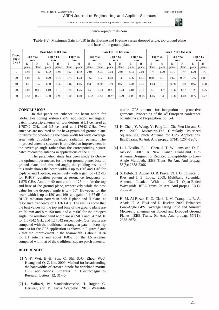
Table-3(c). Maximum Gain in (dB) in the E-plane and H-plane versus drooped angle, top ground plane
and base of the ground plane.
Base GND = 100 mm Base GND = 125 mm Base GND = 150 mm Top = 55
mm Top = 60
mm Top = 65
mm Top = 55
mm Top = 60
mm Top = 65
mm Top = 55
mm Top = 60
mm Top = 65
mm Droop angle (deg.) E-
plane H-
plane E-
plane H-
plane E-
plane H-
plane E-
plane H-
plane E-
plane H-
plane E-
plane H-
plane E-
plane H-
plane E-
plane H-
plane E-
plane H-
plane 0 1.92 1.92 1.92 1.92 1.92 1.92 2.04 2.04 2.04 2.04 2.04 2.04 1.79 1.79 1.79 1.79 1.79 1.79
20 1.82 1.82 1.79 1.79 1.73 1.73 1.52 1.52 1.48 1.48 1.56 1.56 0.81 0.81 0.69 0.69 0.85 0.85
40 1.6 1.57 1.30 1.30 1.46 1.46 0.30 0.30 0.59 0.58 0.70 0.70 -1.14 -1.15 -0.88 -0.90 -0.67 -0.68
60 0.83 0.83 1.10 1.10 1.25 1.25 -0.71 -0.71 -0.23 -0.23 0.10 0.10 -1.9 -1.9 -1.56 -1.57 -1.25 -1.25
80 0.53 0.53 0.90 0.90 1.00 1.00 -0.52 -0.52 -0.29 -0.29 -0.05 -0.05 -1.46 -1.46 -1.08 -1.08 -0.77 -0.77
CONCLUSIONS
In this paper we enhance the beam width for Global Positioning system (GPS) application rectangular patch microstrip antenna of tow designs at L1 centered at 1.75742 GHz and L5 centered at 1.17642 GHz. Two antennas are mounted on the hexa-pyramidal ground plane to utilize for broadening the beam width for wide coverage area with circularly polarized radiation pattern. The improved antenna structure is provided an improvement in the coverage angle rather than the corresponding square patch microstrip antenna in applications of the GPS.
The parametric study has been made to choose the optimum parameters for the top ground plane, base of ground plane, and drooped angle, the yielding results of this study shows the beam width is up to 160o and 170o for E-plane and H-plane, respectively with a gain of -1.2 dB for RHCP radiation pattern at resonance frequency of 1.575 GHz. And a = 40 mm and b = 125 mm for the top and base of the ground plane, respectively while the best value for the drooped angle is α = 50o. However, for the beam width is up to 150o and 160o and gain of -1.67 dB for RHCP radiation pattern in both E-plane and H-plane, at resonance frequency of 1.176 GHz. The results show that the best values for the top and base of the ground plane are a= 60 mm and b = 150 mm, and α = 60o for the drooped angle, the resultant band width are 43 MHz and 54.7 MHz for 1.57542 GHz and 1.17642 respectively. Our results are compared with the traditional rectangular patch microstrip antenna for the GPS application as shown in Figures 6 and 7 that the improvement in the beamwidth is about 180% for L1 antenna and about 160% for the L5 antenna compared with that of the traditional square patch antenna. REFERENCES [1] Y.-F. Wei, B.-H. Sun, C. Shi, S.-G. Zhou, W.-J.
Huang and Q.-Z. Liu. 2009. Method for broadbanding the bandwidths of crossed dipole for wideband marine GPS applications. Progress in Electromagnetics Research Letters. 12: 31-40.
[2] L. Vallozzi, W. Vandendriessche, H. Rogier, C.
Hertleer, and M. Lucia Scarpello. 2010. Wearable
textile GPS antenna for integration in protective garments. Proceeding of the 4th European conference on antenna and Propagation. pp. 1-4.
[3] H. Chen, Y. Wang, Yi-Fang Lin, Che-Yen Lin and S.
Pan. 2009. Microstrip-Fed Circularly Polarized Square-Ring Patch Antenna for GPS Applications. IEEE Trans. 0n Ant. And propag. 57(4): 1264-1267.
[4] L. I. Basilio, R. L. Chen, J. T. Williams and D. R.
Jackson. 2007. A New Planar Dual-Band GPS Antenna Designed for Reduced Susceptibility to Low-Angle Multipath. IEEE Trans. 0n Ant. And propag. 55(8): 2358-2366.
[5] S. Hebib, H. Aubert, O. R. Pascal, N. J. G. Fonseca, L.
Ries and J. E. Lopez. 2009. Multiband Pyramidal Antenna Loaded With a Cutoff Open-Ended Waveguide. IEEE Trans. 0n Ant. And propag. 57(1): 266-270.
[6] H. M. Al-Rizzo, K. G. Clark, J. M. Tranquilla, R. A.
Adada, T. A. Elwi and D. Rucker. 2009. Enhanced Low-Angle GPS Coverage Using Solid and Annular Microstrip antennas on Folded and Drooped Ground Planes. IEEE Trans. 0n Ant. And propag. 57(11): 2368-3672.
21
Related Documents