Basics of Permanent Magnet Motors and Field Oriented Control Ondrej HOLY Tomas DRESLER

Welcome message from author
This document is posted to help you gain knowledge. Please leave a comment to let me know what you think about it! Share it to your friends and learn new things together.
Transcript
Basics of Permanent Magnet Motors and
Field Oriented Control
Ondrej HOLY
Tomas DRESLER
Physics lecture
• Now we’ll take a look at basic physics happening in the motor
• It’s no rocket science and we will discuss only few equations
describing, why the motor turns and what’s the relation between the
current, voltage, momentum, torque and speed
• No more than 10 slides!
2
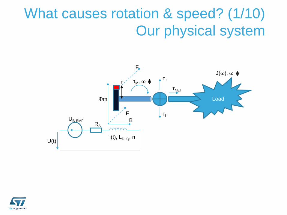
What causes rotation & speed? (1/10)
Our physical system
Load
i(t), LD, Q, n
Φm
r
F τI
τTτM, ω, ϕ
τNET
FJ(ω), ω, ϕ
U(t)
UB-EMFRS
B
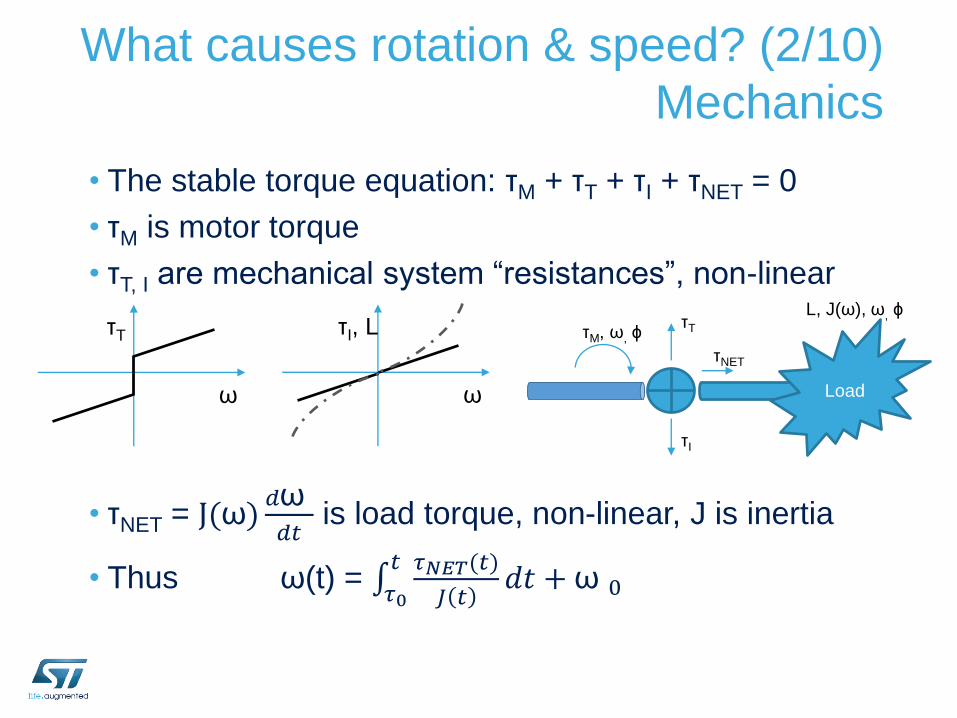
What causes rotation & speed? (2/10)
Mechanics
• The stable torque equation: τM + τT + τI + τNET = 0
• τM is motor torque
• τT, I are mechanical system “resistances”, non-linear
• τNET = J(ω)𝑑ω𝑑𝑡
is load torque, non-linear, J is inertia
• Thus ω(t) = 𝜏0𝑡 𝜏𝑁𝐸𝑇(𝑡)
𝐽 𝑡𝑑𝑡 + ω 0
τT
ω
τI, L
ω Load
τI
τTτM, ω, ϕ
τNET
L, J(ω), ω, ϕ
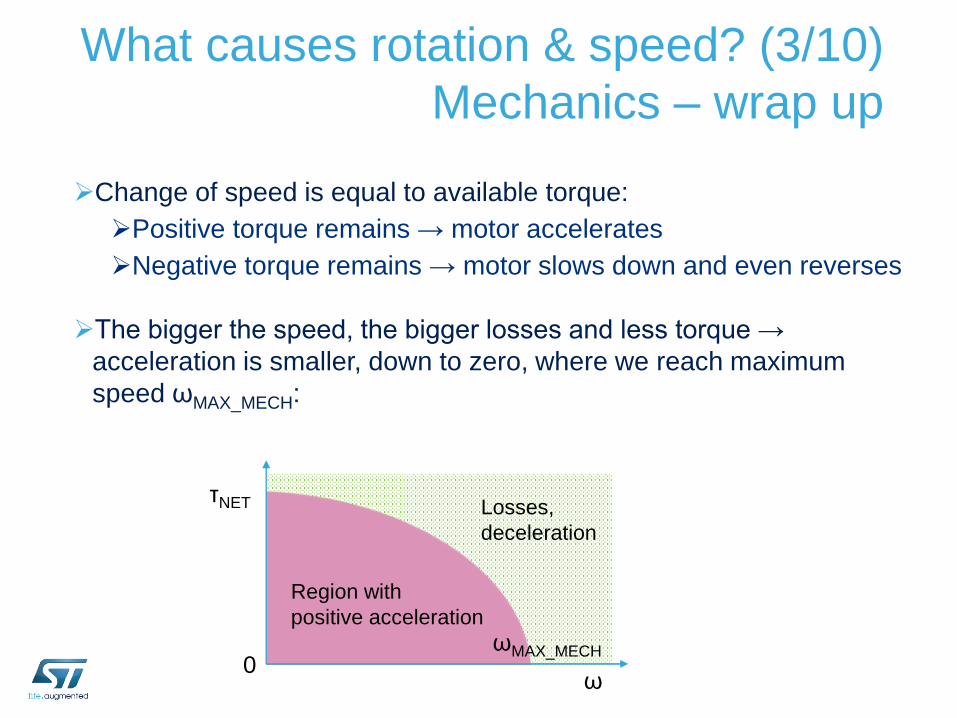
What causes rotation & speed? (3/10)
Mechanics – wrap up
Change of speed is equal to available torque:
Positive torque remains → motor accelerates
Negative torque remains → motor slows down and even reverses
The bigger the speed, the bigger losses and less torque →
acceleration is smaller, down to zero, where we reach maximum
speed ωMAX_MECH:
τNET
0ω
ωMAX_MECH
Region with
positive acceleration
Losses,
deceleration
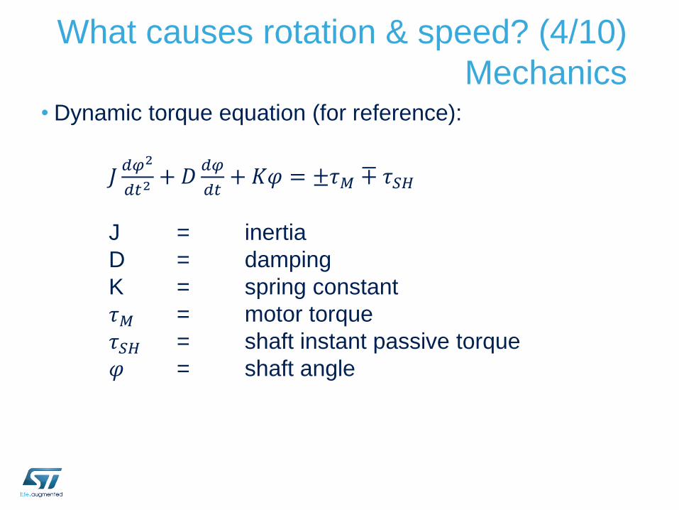
What causes rotation & speed? (4/10)
Mechanics• Dynamic torque equation (for reference):
𝐽𝑑𝜑2
𝑑𝑡2+ 𝐷
𝑑𝜑
𝑑𝑡+ 𝐾𝜑 = ±𝜏𝑀 ∓ 𝜏𝑆𝐻
J = inertia
D = damping
K = spring constant
𝜏𝑀 = motor torque
𝜏𝑆𝐻 = shaft instant passive torque
𝜑 = shaft angle
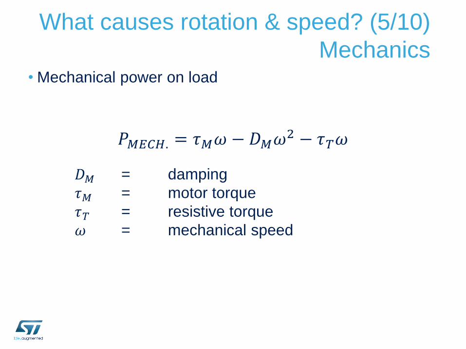
What causes rotation & speed? (5/10)
Mechanics• Mechanical power on load
𝑃𝑀𝐸𝐶𝐻. = 𝜏𝑀𝜔 − 𝐷𝑀𝜔2 − 𝜏𝑇𝜔
𝐷𝑀 = damping
𝜏𝑀 = motor torque
𝜏𝑇 = resistive torque
𝜔 = mechanical speed
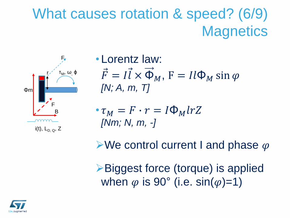
What causes rotation & speed? (6/9)
Magnetics
• Lorentz law:
𝐹 = 𝐼 𝑙 × Φ𝑀, F = 𝐼𝑙Φ𝑀 sin𝜑[N; A, m, T]
• 𝜏𝑀 = 𝐹 ∙ 𝑟 = 𝐼Φ𝑀𝑙𝑟𝑍[Nm; N, m, -]
We control current I and phase 𝜑
Biggest force (torque) is applied
when 𝜑 is 90° (i.e. sin(𝜑)=1)
i(t), LD, Q, Z
Φm
r
F
τM, ω, ϕ
F
B
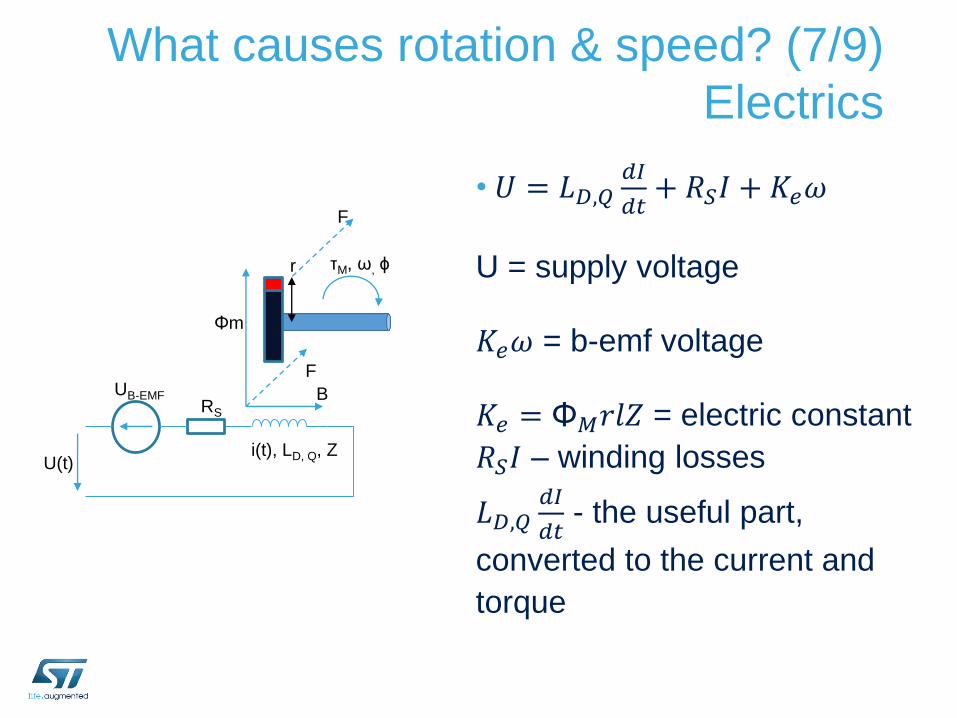
What causes rotation & speed? (7/9)
Electrics
• 𝑈 = 𝐿𝐷,𝑄𝑑𝐼
𝑑𝑡+ 𝑅𝑆𝐼 + 𝐾𝑒𝜔
U = supply voltage
𝐾𝑒𝜔 = b-emf voltage
𝐾𝑒 = Φ𝑀𝑟𝑙𝑍 = electric constant
𝑅𝑆𝐼 – winding losses
𝐿𝐷,𝑄𝑑𝐼
𝑑𝑡- the useful part,
converted to the current and
torque
i(t), LD, Q, Z
Φm
r
F
τM, ω, ϕ
F
U(t)
UB-EMFRS
B
What causes rotation & speed? (8/9)
Electrics – wrap up
• Speed is proportional to the voltage
• Torque is proportional to the current
Torque constant [Nm/A] is proportional to
electrical constant [V/krpm]
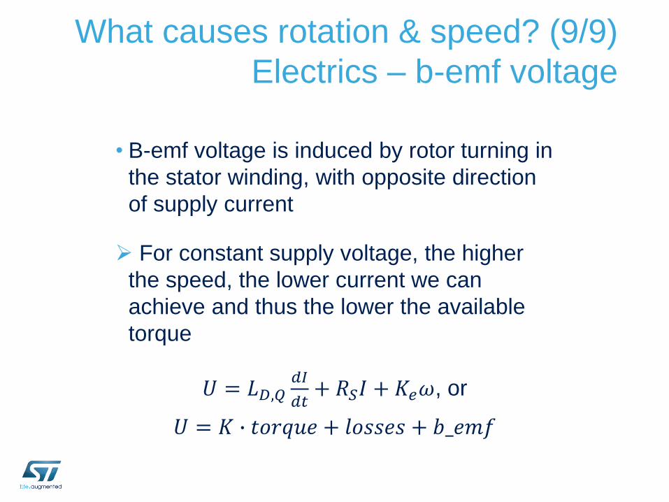
What causes rotation & speed? (9/9)
Electrics – b-emf voltage
• B-emf voltage is induced by rotor turning in
the stator winding, with opposite direction
of supply current
For constant supply voltage, the higher
the speed, the lower current we can
achieve and thus the lower the available
torque
𝑈 = 𝐿𝐷,𝑄𝑑𝐼
𝑑𝑡+ 𝑅𝑆𝐼 + 𝐾𝑒𝜔, or
𝑈 = 𝐾 ∙ 𝑡𝑜𝑟𝑞𝑢𝑒 + 𝑙𝑜𝑠𝑠𝑒𝑠 + 𝑏_𝑒𝑚𝑓
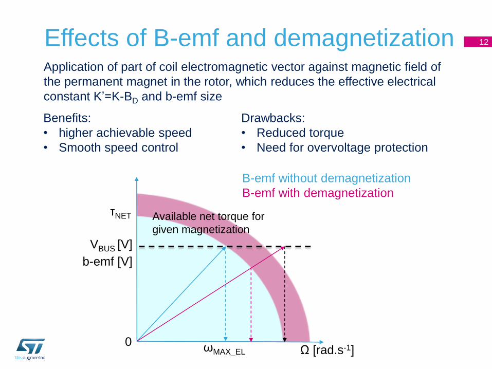
Effects of B-emf and demagnetization 12
VBUS [V]
0Ω [rad.s-1]ωMAX_EL
B-emf without demagnetization
B-emf with demagnetization
b-emf [V]
τNET Available net torque for
given magnetization
Application of part of coil electromagnetic vector against magnetic field of
the permanent magnet in the rotor, which reduces the effective electrical
constant K’=K-BD and b-emf size
Benefits:
• higher achievable speed
• Smooth speed control
Drawbacks:
• Reduced torque
• Need for overvoltage protection
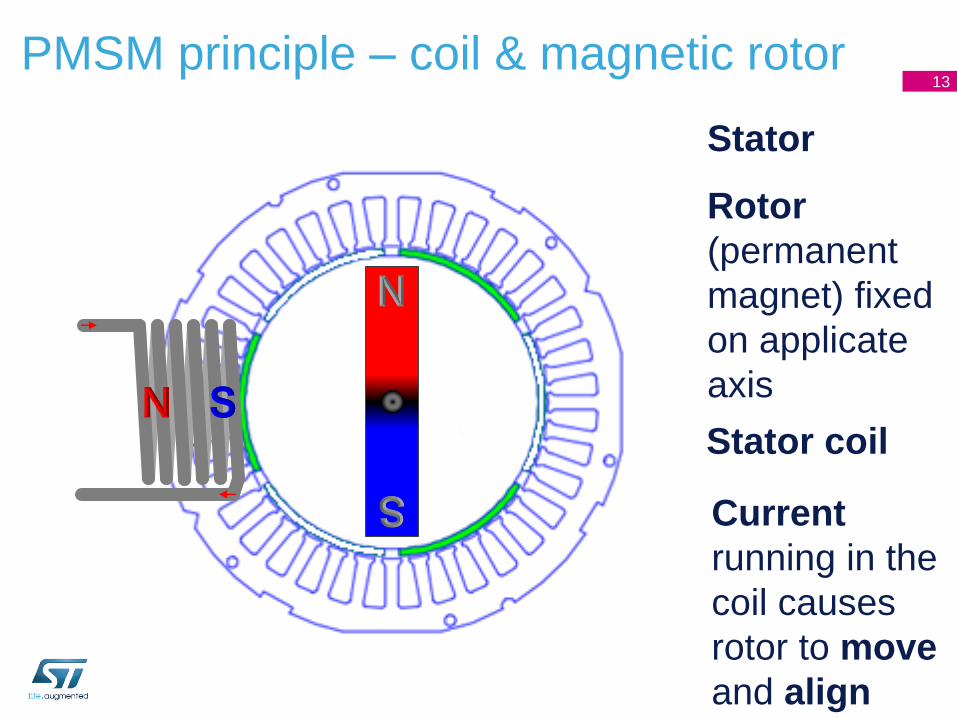
Stator
PMSM principle – coil & magnetic rotor13
Rotor
(permanent
magnet) fixed
on applicate
axis
Stator coil
Current
running in the
coil causes
rotor to move
and align
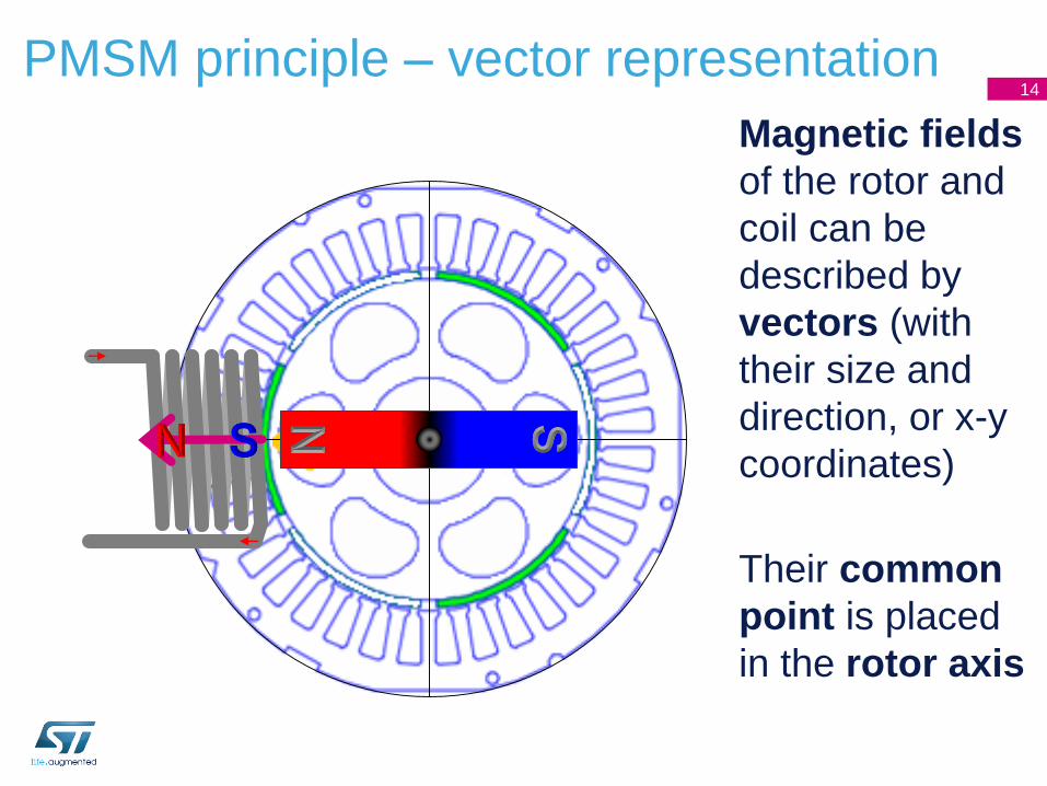
Magnetic fields
of the rotor and
coil can be
described by
vectors (with
their size and
direction, or x-y
coordinates)
PMSM principle – vector representation 14
Their common
point is placed
in the rotor axis
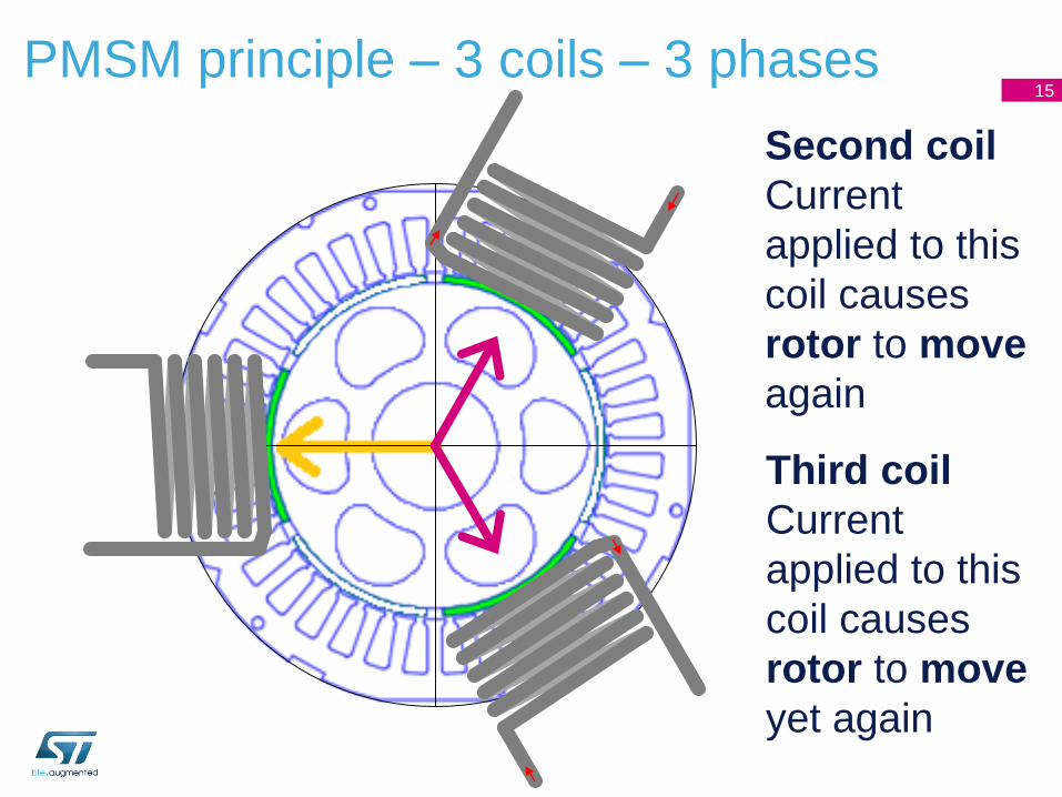
PMSM principle – 3 coils – 3 phases15
Second coil
Current
applied to this
coil causes
rotor to move
again
Third coil
Current
applied to this
coil causes
rotor to move
yet again
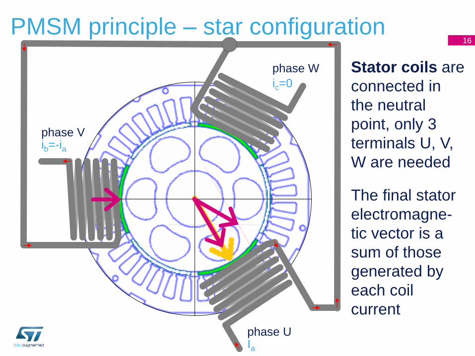
PMSM principle – star configuration16
phase UIa
phase V
phase W
ic=0
Stator coils are
connected in
the neutral
point, only 3
terminals U, V,
W are needed
The final stator
electromagne-
tic vector is a
sum of those
generated by
each coil
current
ib=-ia
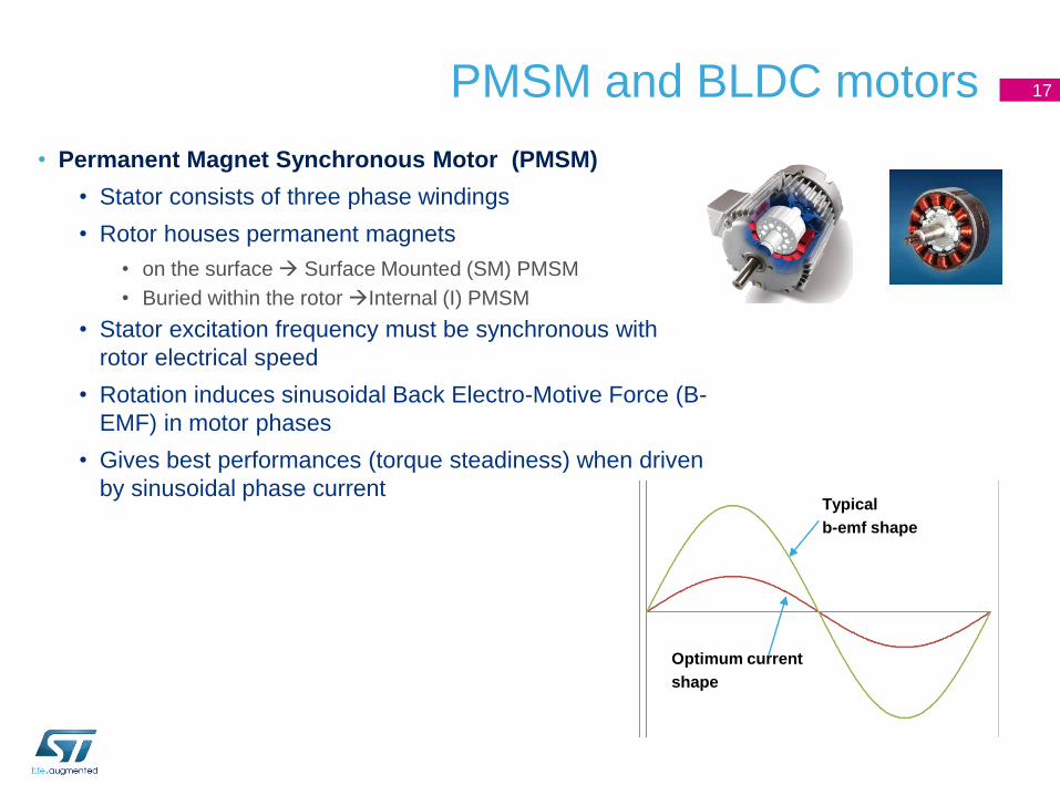
PMSM and BLDC motors
• Permanent Magnet Synchronous Motor (PMSM)
• Stator consists of three phase windings
• Rotor houses permanent magnets
• on the surface Surface Mounted (SM) PMSM
• Buried within the rotor Internal (I) PMSM
• Stator excitation frequency must be synchronous with
rotor electrical speed
• Rotation induces sinusoidal Back Electro-Motive Force (B-
EMF) in motor phases
• Gives best performances (torque steadiness) when driven
by sinusoidal phase current
17
Typical
b-emf shape
Optimum current
shape
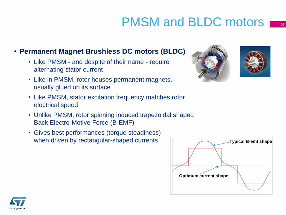
PMSM and BLDC motors 18
• Permanent Magnet Brushless DC motors (BLDC)
• Like PMSM - and despite of their name - require
alternating stator current
• Like in PMSM, rotor houses permanent magnets,
usually glued on its surface
• Like PMSM, stator excitation frequency matches rotor
electrical speed
• Unlike PMSM, rotor spinning induced trapezoidal shaped
Back Electro-Motive Force (B-EMF)
• Gives best performances (torque steadiness)
when driven by rectangular-shaped currents Typical B-emf shape
Optimum current shape
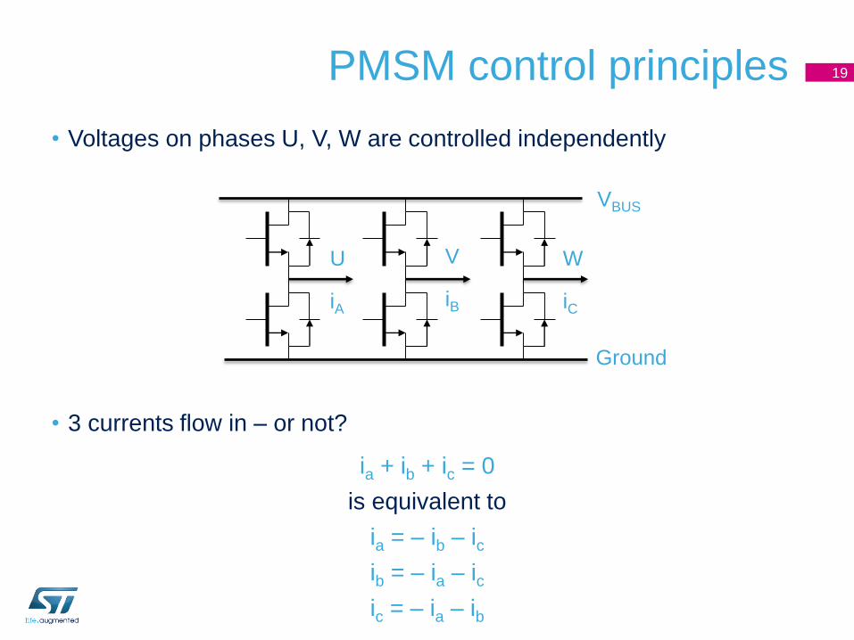
• Voltages on phases U, V, W are controlled independently
• 3 currents flow in – or not?
ia + ib + ic = 0
is equivalent to
ia = – ib – ic
ib = – ia – ic
ic = – ia – ib
PMSM control principles 19
VBUS
Ground
U
iA
V
iB
W
iC

PMSM control principles
• All mentioned methods use Pulse Width Modulation with fixed
frequency and variable pulse length to control effective voltage on the
phases
• Block commutation
• Historically used
• Simple to implement
• Drawbacks in control: higher torque ripple, slow reaction on load change
• Sinusoidal Field Oriented Control (FOC)
• More complicated and more expensive
• More difficult to implement, requires DSP-like functionality
• Rapid reaction on torque/load change, low torque ripple, full 4-quadrant operation
20
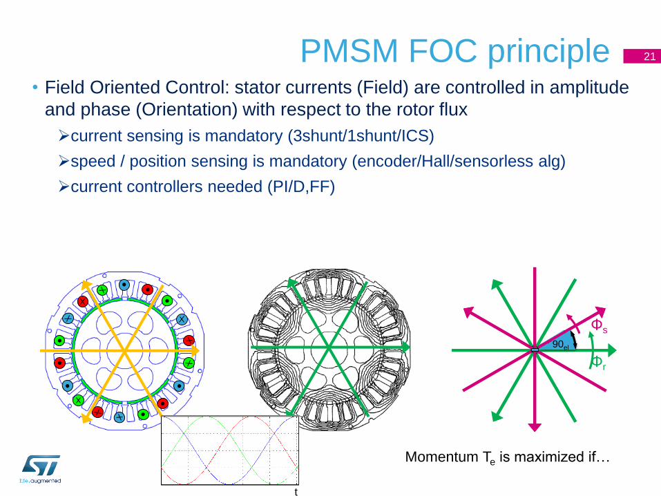
PMSM FOC principle• Field Oriented Control: stator currents (Field) are controlled in amplitude
and phase (Orientation) with respect to the rotor flux
current sensing is mandatory (3shunt/1shunt/ICS)
speed / position sensing is mandatory (encoder/Hall/sensorless alg)
current controllers needed (PI/D,FF)
21
Momentum Te is maximized if…
Φr
Φs
90el90el
t
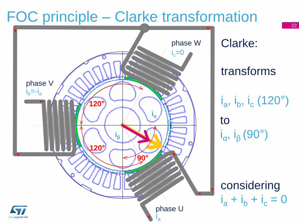
FOC principle – Clarke transformation22
phase UIa
phase V
phase W
ic=0
iα
iβ
Clarke:
transforms
120°
120°
90°
ib=-ia
ia, ib, ic (120°)
to
iα, iβ (90°)
considering
ia + ib + ic = 0
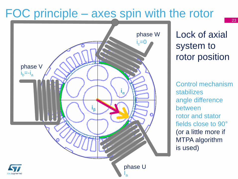
FOC principle – axes spin with the rotor23
phase UIa
phase V
phase W
ic=0
iα
iβ
Lock of axial
system to
rotor position
ib=-ia
Control mechanism
stabilizes
angle difference
between
rotor and stator
fields close to 90°
(or a little more if
MTPA algorithm
is used)
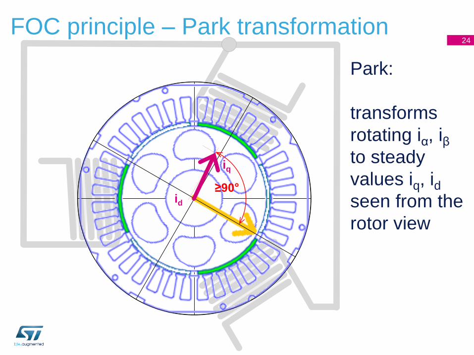
FOC principle – Park transformation24
Park:
transforms
rotating iα, iβto steady
values iq, idseen from the
rotor view
≥90°
iq
id

Why FOC ? 25
• Best energy efficiency even during transient operation.
• Responsive speed control to load variations.
• Decoupled control of both electromagnetic torque and flux.
• Acoustical noise reduction due to sinusoidal waveforms.
• Active electrical brake and energy reversal.
ąß
Clarke Park Park -1
Independent control
of flux and torque
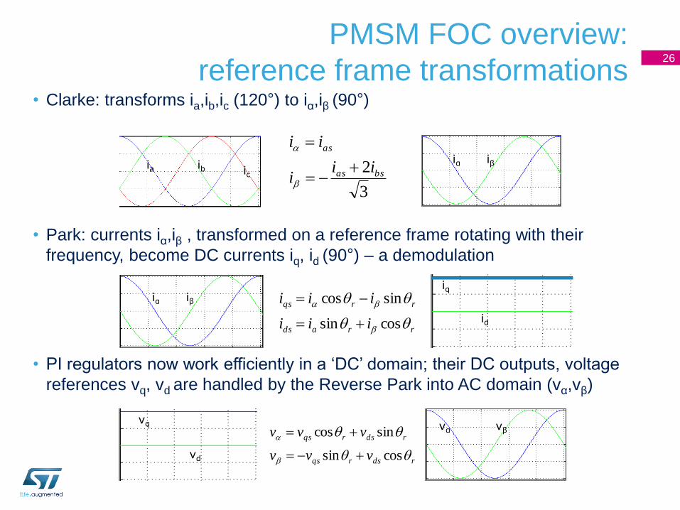
PMSM FOC overview:
reference frame transformations26
• Clarke: transforms ia,ib,ic (120°) to iα,iβ (90°)
• Park: currents iα,iβ , transformed on a reference frame rotating with their
frequency, become DC currents iq, id (90°) – a demodulation
• PI regulators now work efficiently in a ‘DC’ domain; their DC outputs, voltage
references vq, vd are handled by the Reverse Park into AC domain (vα,vβ)
3
2 bsas
as
iii
ii
ia ib ic
iα iβ
rrads
rrqs
iii
iii
cossin
sincos
iα iβ
iq
id
rdsrqs
rdsrqs
vvv
vvv
cossin
sincos
vq
vd
vα vβ
Related Documents