EPOCHE 2013 LLP ERASMUS IP Excellence in Photogrammetry for Open Cultural Landscape & Heritage Education

Welcome message from author
This document is posted to help you gain knowledge. Please leave a comment to let me know what you think about it! Share it to your friends and learn new things together.
Transcript

EPOCHE 2013 LLP ERASMUS IP
Excellence in Photogrammetry
for Open Cultural Landscape & Heritage Education
June, 2013

CONTENTS
1. Introduction
2. Topography and Photography
2.1 Levels data 2.2 Field measurements
3. Photogrammetric Image Processing
3.1Working with Photomodeler Scanner 3.2Working with Photoscan 3.3Working with VeCAD
4. Digital 3D Modelling
5. Conclusion and Discussion
6. Acknowledgements
7. Bibliography
8. Appendix A’
9. Appendix B’

1. INTRODUCTION
The EPOCHE LLP Erasmus Intensive Program IP (Excellence in Photogrammetry for Open Cultural Landscape & Heritage Education is about the improvement of traditional methods for surveying, documenting and Web-based Education for Archaeological Sites and Cultural Landscapes & Heritage, using low-
cost techniques as innovative practices under digital Photogrammetry. This paper presents tools and applications for 3D digitization, for the analysis of 3D artefacts and associated information.
Group A members came to Thassos with Eppoche LLP Erasmus in order to produce digital 3D models of objects with historical interest. The members from the group are from different countries. The software used were the following: VeCAD,Autocad,PhotoModeler ,Photoscan and Calib in order to make the 3D models and the ortophotoplane.
Keywords: Photogrammetry, Photomodeler, Photoscan, VeCAD, Calibration, 3D Modeling, Orthophotoplane,Autocad.
2. TOPOGRAPHY AND PHOTOGRAPHY
2.1 Levels data
Starting with topography and photography in order to collect the primary data (first level data). The first level data are measurements like distances, angels and images.
After we take the measurements we are going to the office to produce the second level data (coordinates) based on the first level data. Downloading the measurements from the total station into the computer and put them in excel to calculate the errors in order to use them.
The third level is based on the second level data where we produce 3D modeling using Photomodeler.
The forth level could be something based on third, could be a multimedia. The section of a model is a fourth level data.
The fifth level is the more important .Here the project has to be done; we have to make the decision.
2.2 Field measurements
The field measurements ore based on collecting information, measurements, points and photos on each project. First we must go on the field and study the building to know how to start the procedure and draw sketches from the group to note the control points.

The Facede (VeCAD) We used a non metric camera, switched off the auto-focus function. The
camera that has been used was from Fujifilm with the following characteristics.
Fujifilm Finepix J20
General Dimensions 91 x 56 x 17.4 m Weight 96.5 g
Image Capture Digital video capture Yes Face recognition Yes
Max. image resolution (new) 3648 x 2736 Inside The Camera Optical sensor CCD
Zoom range 3 Light sensitivity Auto, ISO 64/100/200/400/800/1,600
Lens aperture F3.1 to F14.1 Shutter speed 8 to 1/2000 sec Focal length 35mm to 105mm (35mm equivalent) Creative controls Yes Sensor Resolution (max) 10 megapixels Resolution 10 megapixels Normal focus range (min) 40 cm Macro focus range (min) 10 cm Photodetectors (max) 10 million Photodetectors (effective) 10 million
Outside The Camera Viewfinder type NoneType of flash Built-inTripod mount YesVideo out YesBattery charger Adapter includedStorage type(s) Secure Digital, Secure Digital HCLCD size (new) 2.7 inch
Image size sensor Width 6.17 Height 4.55
The photos that were taken on the field must be calibrated using Calib software. Before calibrating the pictures, we have to load the parameters of the camera into the program.
The control points from the building are measured using a total station from Topcon South Nts 325r.

Total Station South NTS-325
The NTS series Total Stations are versatile with complete on-board applications. The internal memory is available up to 8000 points. The body style is similar to a Topcon Total Station and is combined with easy to use operation. The smart appearance and advanced operations are as attractive as its price. Product Introduction:1. Handy EDM, Big Memory2. High Accuracy & Long Measuring Range3. Convenient Data Management System4. Complete Compensation Application5. Compensation Auto Electronic6. Long-time Working Battery
7. Superb Waterproof & Dustproof FunctionsSPECIFICATION:* Measuring Range (under fair weather condition) : -1 P = 1.6KM -3 P = 2.3KM* Accuracy: 5 " 3 + 2 PPM Measurement Method: -Horizontal = Dual -Vertical = Dual* Display: Double Side
The Pillar of ancient temple (pic. 3) (Photomodeler Scanner)
The steps in order to do a 3D models are:Use-d non metric camera, switched off the auto-focus functionCalibrated in Photomodeler scannerArtificial targets were put around the objectPhotos were taken including at least six common points from next
one (pic. 1)With manual measure, member of the group took distances and
sketched it.
picture 1

The Memorial War Monuments (pic.2 ) (Photomodeler scanner)It was done in the same way like the pillar of ancient temple as we can see in
the next chapter.
The Artefact and the Lion sculpture (Photoscan)
We using the same non metric camera switched off the auto-focus function to take picture of the sculpture. Photos were taken around the object by covering all the surfaces from different angles. With manual measure using a measuring tape, member of the group took at least 2 distances: one horizontal and another vertical and sketched them in order to verify if the project in Photoscan was correctly done.
3. PHOTOGRAMMETRIC IMAGE PROCESSING
3.1 Working with Photomodeler Scanner
First step was to choose a digital non-metric camera, Fujifilm Finepix J20 with 10 mega pixels, switched-off the autofocus function. After that, we choose monuments with historic interest (standing pillar from old temple (pic.3) and a remembering monuments (pic.2) about national’s heroes.
picture 2 picture 3
The next step was on the field observing the monuments. After studying the place, artificial targets were put around the objects in order to take photos of the

monuments from the same distance making a circle to each of them. The photos were taken in order to have at least six common targets, photo by photo. Also a sketch was made to note the distances.
Back to the office work, using the software the camera needs to be calibrated. Taking nine photos of the artificial target (pic.4), one horizontal, one vertical in each side and one top.
picture 4
The next step is to open Photomodeler Scanner camera calibration project and import the photos(pic.5 ).After that go next and execute calibration. The saved project button was click in order to save the calibrated photos.
picture 5 picture 6
After finishing camera calibration the project in Photomodeler Scanner requires some steps before finishing the 3D model. First we restarted the software after that the basic line project. The pictures from the object are imported (first we worked with monument).The next step is to recognize the camera. From the photos that were taken on the field only some of them are chosen to work with in modeling.

By clicking on two photos they appeared to interface, the program is working with two photos at the same time. In order to orient the picture, at least six points has to be found .After selected the points on each photo, the button reference the points is activated. F5 or process to orient the photos is the command to make the program processing those two photos.
Points from the picture that was oriented now can be connected using lines. After that opening 3D view the lines and the points can be noticed on the screen.
Now that there are two photos oriented, a third photo must be opened and select the common points with the first 2 photos oriented.

Joining six points from new photo and the old photo the orientation of the third photo is in process. Repeating this process with all the selected photos which were chosen at first the monument is oriented. Very important function was marking points mode which put the points in photos.
After points and lines were drawn in the software the next step is to create surfaces using the command markingsurface toolspath mode. For putting photos on 3D model view, choosing options and fast texture and the quality texture. After finishing all the steps the monument is done in 3D model. It can be rotated at 360 degrees to see the entire monument.
To verify that the work was done correctly we have to measure on the 3D models the same dimension that was measured on the field. If they are equal that means the 3D model was done correctly.
At the end the final step is to export the project in different files like .dxf, .3ds, .wrl.

After finishing with the monument the next step is to do the pillar in the same way using also Photomodeler repeating the same steps in order to model the Pillar monument, but with some additional steps due to its complicated and different shape.
The pictures from the object are imported (first we worked with monument). The next step is to recognize the camera. From the photos that were taken on the field only some of them are chosen to work with in modeling.
By clicking on two photos they appeared to interface, the program is working with two photos at the same time. In order to orient the picture, at least six points has to be found. After selected the points on each photo, the button reference the points is activated. F5 or process to orient the photos is the command to make the program processing those two photos. Points from the picture that was oriented now can be connected using lines. After that opening 3D view the lines and the points can be noticed on the screen.
Now that there are two photos oriented, a third photo must be opened and select the common points with the first 2 photos oriented.
Joining six points from new photo and the old photo the orientation of the third photo is in process. Repeating this process with all the selected photos which were chosen at first the monument is oriented. Very important function was marking points mode which put the points in photos .After points and lines were drawn in the

software the next step is to create surfaces using the command markingsurface toolspath mode. For better results open 3D models view, choosing options and fast texture and the quality texture.
Another function when creating the pillar is Mark cylinder mode> create cylinder line in order to do draw more accurate shape of the pillar. The base of the cylinder is curve. The curve is made using the same points in two photos with referenceproceed.
After finishing all of the step the pillar is done in 3D model. It can be rotated at 360 degrees to see the entire pillar. To verify that the work was done correctly we have to measure on the 3D models the same dimension that was measured on the field.If they are equal that means the 3D model was done correctly.
At the end the final step is to export the project in different files like .dxf, .3ds , .wrl.
3.2Working with Agisoft PhotoScan
First step was to prepare the camera, switch off the autofocus. Then to pick an object, in this case Group 1 chooses a Crouching Lion which was found in the area of the Gate of Sotas, probably late Hellenistic Period. Also the group worked on an ancient Artefact from the garden of the museum.

Group A took photos with common points around the object covering all surfaces from different angles. Also took manual measurements and made sketches of it.
Back to base Group A worked on the software Photoscan. First steps to create the models was to open Photoscan. Importing the photos using Add chunk>right click>add new photos. In this project is good to work with many photos .The photos must be taking properly not with half a picture in shadow and the other half at the light.
Opening first photo> Intelligent scissors and click around the object, removing unnecessary objects .When was done, invert selection>add selection. Repeated this with all the photos .Choose all the photos>workflow>align photos. Unchecked contain features by mask and after that process points. The geometry is built using the command: workflow>built geometry>exact methods>high quality.

Face count 2000000>ok>process .Finally using the command build texture>blending mode average>mapping mode generic the artifact is done by pressing the ok button.
The final result it will look like in the picture.
At the end after finishing the lion and the artefact the program must be exported in .3ds, .wrl, .dxf formats.

3.3 Working with VeCad
To create a Photogrammetric Rectification based on Measured Control Points had executed some steps. First, go on the field and took some measurements of the control points and photos of the building which were used to rectify the images. For the measurements we using a total station from Topcon South Nts-325r and for taking photos a camera from Fujifilm Finepix J20 with 10 mega pixels.
After finishing the measurements and taking photos, downloading them and put them in excel to correct the errors and to find the final x, y, z. The next step is to copy the final coordinates in a txt file created with Notepad.
Before starting working in VeCad first calibration of the images that were selected for the rectification has to be done.
In order to calibrate the camera, we took four photos of the target, and inserted them in Calib software. After that adding camera image sensor that were searched on web and number of rows and columns, now the parameters of the camera can be calculated.

After that putting our photos in the program and loading the parameters the photos can be calibrated and the rectification can be started.
Starting the specialized software VeCad with the button can be inserted control points in the Cad environment. The format of control points should be id XY.
Because the text was too big, selecting it and changed the size of the text using the window properties, text height.
Using the main menu item InsertRaster Image inserting a .bmp image of
the facade to be rectified. Placing the image using a rectangular region and fit the image in a good scale in the current drawing, in order to identify both the ground control points location and their codes and their corresponding location on the image.
First locate the control points on the image, in order to de that place point drawing elements on the image to identify the ground control points, using the

command ‘Creates single point’ from the toolbar. After finishing place the points activate the command to start the
image rectification. Activating the button first and then selecting the whole image to rectify and pressed the right mouse button. Identifying the points from the first image and match those with the ground control points, using the
following button indentifying firstly a control point on the image and then his correspondent point in ground space.
After selecting all the points click the right mouse button. It appeared a report dialog where were the standard deviation error of rectification. (pic.24)
picture 7
After clicking OK, we give the image file name of the rectified image and to specify the pixel size in ground coordinate.
The rectification of the image was done. After finishing with the first picture the next step is to start doing the other image in the same mode and the project will be finished. (pic.25)

picture 8
The next step after rectifying the images from the house in VeCad is to open the new software called Autocad where using the command InsertRaster Image the house is placed on the program. Creating new layers for the house, we can start drawing the rocks and the margins of the building. After finishing drawing the raster image can be removed. Before close the software, when saving the program it must be saved together with the photo that was used. (pic.26)
picture 26

4. DIGITAL 3D MODELING
We use 3D Modeling of realworld objects, buildings and scenes, including virtual reconstruction of historical buildings and monuments that no longer or only partially exist digital documentation of historical buildings and monuments for restoration purposes in case of fire, flood, war, earthquake. Also, the ability for virtual interaction without the risk of damage and production of e-learning data for educational resources, virtual tourism, virtual museum exhibits and interactive on demand 3-d visualization of the object, building or scene. 3D Modeling applications include:
digital documentation of buildings
monuments and sites

robot navigation and obstacle recognition augmented and virtual reality architectural surveying computer games virtual tourism forensics and inverse camera sciences
The lion

The artifact
These applications specify requirements, such as high geometric accuracy, details capturing, quality photorealism, virtual video-on-demand, high automation and low user interaction, low cost, models for 3D digitization and data processing (Athanasios D. Styliadis, Automation in Construction, 2008).
5. CONCLUSIONS AND DISCUSSION
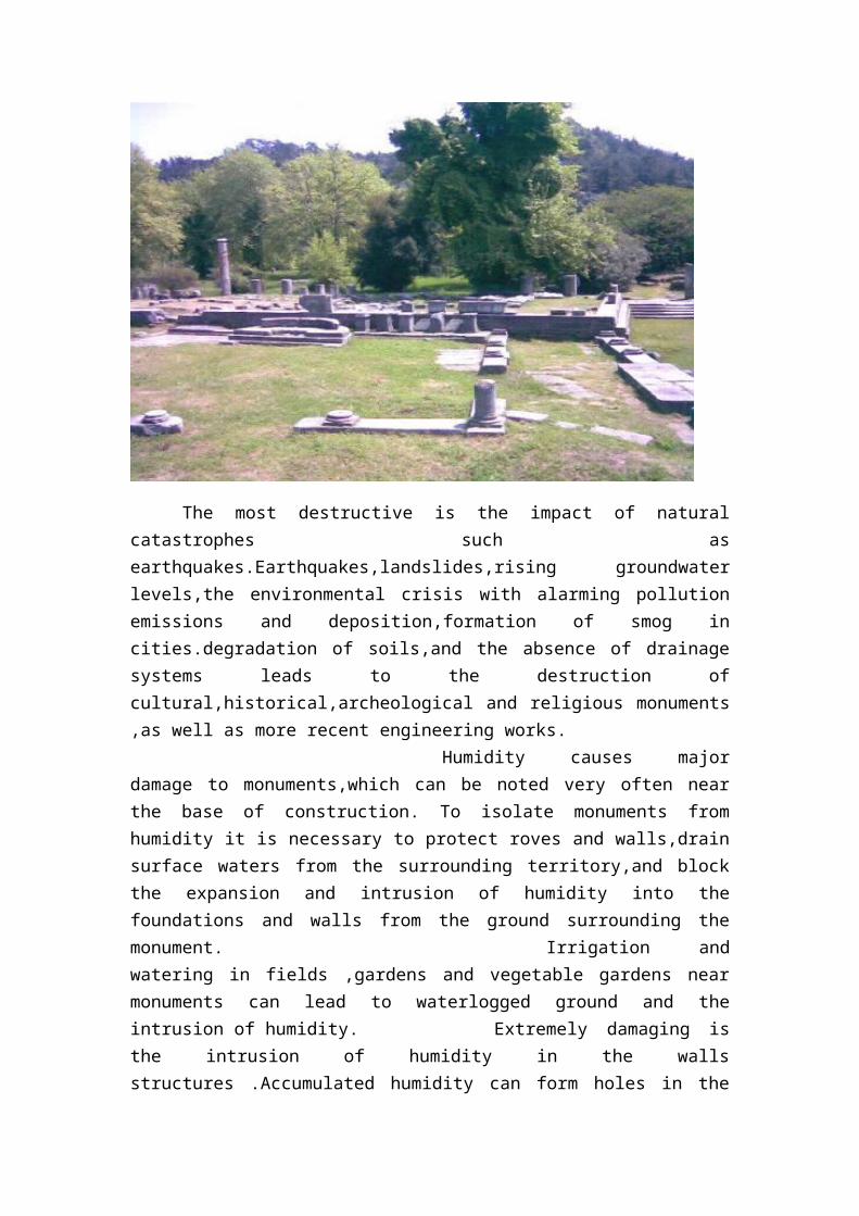
The historic environment is made up of the buildings, monuments, sites and landscapes that reflect our history. If we did not have measures in place to protect and conserve the historic environment, important places would risk being changed and losing what makes them special, or being destroyed and lost forever.

The most destructive is the impact of natural catastrophes such as earthquakes.Earthquakes,landslides,rising groundwater levels,the environmental crisis with alarming pollution emissions and deposition,formation of smog in cities.degradation of soils,and the absence of drainage systems leads to the destruction of cultural,historical,archeological and religious monuments ,as well as more recent engineering works.
Humidity causes major damage to monuments,which can be noted very often near the base of construction. To isolate monuments from humidity it is necessary to protect roves and walls,drain surface waters from the surrounding territory,and block the expansion and intrusion of humidity into the foundations and walls from the ground surrounding the monument.
Irrigation and watering in fields ,gardens and vegetable gardens near monuments can lead to waterlogged ground and the intrusion of humidity.
Extremely damaging is the intrusion of humidity in the walls structures .Accumulated humidity can form holes in the walls,freezing in the winter,melting in the spring and destroying mortar,thus separating internal and external layers and weakening the structure of the monument.This mainly causes damage to the south and in part the western walls of monumens,whereas northem and eastern faces usually remain less damaged as a consequence of smaller temperature fluctuations.
Recommendations for necessary measures
Offices responsible for urban areas ,for environmental protection and for historical and cultural monuments protection should elaborate basic environmental and urban plans,identifying environmentally unfavorable territories and creating programs of environmental activities.
In the elaboration of general plans, detailed plans and projects, it is necessary to consider their possible negative impacts and separate these from the protected zones of cultural and historic monuments (historic, administrative, and natural boundaries), regulating built-up zones and protecting natural landscape zones.
Near zones for protected historic and cultural monuments, projects reviews should be the basis for detailed planning and construction of territorial districts and other settlements. Construction and other works, as well as economic activities within such zones, should be implemented only with the permission of the authorized state body.
It is necessary to investigate existing geological and related conditions surrounding monuments, in particular those, such as environment pollution, causing damages.
6. ACKOWLEDGEMENTST
This paper is the result of a team work from the ERASMUS IP Project sustained by The European Union. The team was formed from five students from four different countries: Romania, Hungary,Slovakia and Greece.The Group A wish to

thank to Doctor Professor A.Styliadis ,Doctor T. Jancso, Lecturer S. Herban, Prof. Ing. A. Kopacik, Phd., Doctor L.Sechidis, the organization comitee.
7. BIBLIOGRAPHY
http://downloads.agisoft.ru/pdf/photoscan-pro_0_9_0_en.pdf http://www.photomodeler.com/products/scanner/default.html
http://vecad-dll-ocx.soft32.com/
8.APPENDIX A’
Description and Historic Data of Thassos Island
Thassos is the northern island of Thrakiki sea in Greece, across the coast of eastern Macedonia, near the Gulf of Keramoti and the Nestos River Delta. The tradition has linked its name with Thassos, son of Poseidon or other version of Aginora, king of the Phoenicians.
According to official historical evidence the first inhabitants of the region were Phoenicians, who installed a commercial station in Thassos. It has previously described as the greenest island, a small nursery in the middle of the sea. The term Ypsario (1,127 m,) is full of cedar trees, fir trees, oaks and chestnuts, and the lower the altitude, stick up olives, and pine trees, framing the endless beaches. The nature dominated by two entities: the northeast dominated by steep ravines, while the southwest shore overgrown leads smoothly into riches beaches. It is such a natural attraction to identify, according to mythology, Thasos island of the Sirens.
picture 9

Some, exported products are minerals like gold and iron, marbles, timber and wine. Thassos is the homeland of the famous painters Polygnotos, Aglaophon, Aristophon, of the sculpturists Polycletus, Sosicles, Pythagoras, of the satirical poet Hegimon, of the sophist Stisimvrotos, of the great Olympic winner Theagenis. Currency of Thassos is rich and aesthetically significant and was kept for seven centuries. . There is also, one of the largest museums in northern Greece and the most important in Eastern Macedonia and Thrace which exhibits Thassos Archeological findings from the historic to the Byzantine period. The centre of the religious belief of Thassians, as well as of all ancient Greeks was the Greek twelve Gods of Olymp, while nowadays they are Christian Orthodox.
9.APPENDIX B’
A.Photomodeler ScannerPhotoModeler helps you create accurate, high-quality 3D models and
measurements from photographs using your own camera. PhotoModeler is the baseproduct. PhotoModeler Scanner contains all the capabilities of PhotoModeler, andadds scanning and dense surface modeling.
PhotoModeler as the base product is a powerful and affordable tool to build accurate models and get measurements from your photos. Use PhotoModeler to build:
CAD-like models of a wide variety of objects and scenes. Models using points, lines, edges, surfaces (photo textured or shaded) and
other entities. Automated projects, using the included target detection features
PhotoModeler's main features:Easy to Use and Learn: Includes an advanced Windows user interface,
Wizards for easy project set-up, extensive multimedia tutorials, printed user guide, and extensive on-line help.
Modeling Tools: Create models using PhotoModeler's Point, Line, Curve, Edge, Cylinder, and Shape marking tools.
Surface Tools: Add surfaces to features defined by Points, Lines, Curves, and Edges. Create NURBS Surfaces from Lines, Edges, and Curves.
Photo-textures: Add photo-textures and colours to surfaces. Export textures with 3DS, OBJ, VRML, and 3DM.
3D Viewer: View, measure, select objects, and interactively rotate the created 3D models with full photo-textures.
Measurement Tools: Perform point, distance, length and area measurements right within PhotoModeler.
Coded Targets: Automate the setup (initial marking and referencing) of the project, or the extraction 3D data points using targets with a special code ring that the

software recognizes in the images. See Automation and Coded Targets.Scale/Rotate/Translate: This feature provides you the ability to apply proper
scale to your project and set your model in the proper coordinate system for exporting.
Export Capabilities: Export your model to Autodesk DXF (2D and 3D), 3D Studio .3ds, Wavefront OBJ, VRML (1&2), IGES, OpenNURBS/Rhino, StereoLithography STL, RAW, Maya Script, Max Script, FBX, and Google Earth’s KML and KMZ. See the Exports page.
Import Capabilities: Import 3D data for use as control points, affine (coordinate systems), mesh comparison, or photo projection.
Photograph Handling: Work with any number of photographs, add new photographs at any time, and import many different image formats. * Image Control: Use extensive Zoom Tools for accurate sub-pixel marking, Photo Rotate for easier viewing, and Image Enhancement for increased visibility.
Camera Support: Use images from digital, film, or video cameras. Automatic Camera Orientation determines the position of the camera when the image was taken. Use different cameras in the same project.
Camera Calibrator: Accurately measure your camera's focal length, principal point, digitizing aspect ratio and lens distortion.
Photo-Projections: Check project quality by projecting 3D data onto your photos.
Customizable Interface: Control the layout and appearance of your PhotoModeler screen. Customizable items include toolbars, short cut keys, and colors for items such as 3D objects, Projections, and the 3D Viewer.
Architecture and PreservationPhotoModeler software is widely used as a measurement and modeling tool in
architectural, preservation, conservation and cultural resource management applications for:
Documenting and measuring older buildings and structures for conservation and preservation
Generating 3D models for visualization and view studiesGenerating elevation drawings of your existing structuresGenerating rectified photographs of facades from single and multiple photo
projects Producing photo-textured 3D models for realistic walk-bys Surveying existing structures and objects With PhotoModeler Scanner, obtain scans of facades, esp. those with complex shapes and
B.Agisoft PhotoScan Agisoft PhotoScan is an advanced image-based 3D modeling solution aimed at
creating professional quality 3D content from still images. Based on the latest multi-view 3D reconstruction technology, itoperates with arbitrary images and is efficient in

both controlled and uncontrolled conditions. Photos can be taken from any position, providing that the object to be reconstructed is visible on at least two photos. Both image alignment and 3D model reconstruction are fully automated.
Generally the final goal of photographs processing by PhotoScan is to build a textured 3D model. The procedure of photographs processing and 3D model construction comprises three main stages. 1. The first stage is photographs alignment. At this stage PhotoScan searches for common points on photographs and matches them, as well as it finds the position of the camera for each picture and refines camera calibration parameters. As a result a sparse point cloud and a set of camera positions are formed. The point cloud represents the results of photos alignment and will not be directly used in the further 3D model construction procedure (except for the point cloud based reconstruction method). However it can be exported for further usage in external programs. For instance, the point cloud model can be used in a 3D editor as a reference. On the contrary the set of camera positions is required for further 3D model construction by PhotoScan. 2. The next stage is building geometry.
Based on the estimated camera positions and pictures themselves a 3D polygon mesh, representing the object surface, is build by PhotoScan. Four algorithmic methods available in PhotoScan can be applied to 3D mesh generation: Arbitrary - Smooth, Arbitrary - Sharp, Height field - Smooth and Height field - Sharp methods. Additionally there is a Point Cloud based method for fast geometry generation based on the sparse point cloud alone. Having built the mesh, it may be necessary to edit it. Some corrections, such as mesh decimation, removal of detached components, closing of holes in the mesh, etc. can be performed by PhotoScan. For more complex editing you have to engage external 3D editor tools. PhotoScan allows to export the mesh, edit it by another software and import it back. 3. After the geometry (i.e. the mesh) is constructed, it can be textured and / or used for orthophoto generation. Several texturing modes are available in PhotoScan, they are described in the corresponding section of this manual.
Before loading your photographs into PhotoScan you need to take them and select those suitable for 3D model reconstruction. Photographs can be taken by any standard digital camera, as long as you follow some specific capturing guidelines. This section explains the general principles of taking and selecting pictures that provide the most appropriate data for 3D model generation.
Basic rules
Use a digital camera with reasonably high resolution (5 MPix or more). Wide angle lenses suit better for reconstructing spatial relations between
objects than telephoto ones. Avoid not textured and flat objects or scenes. Avoid shiny and transparent objects. Avoid unwanted foregrounds and moving objects as much as possible. Shoot shiny objects under a cloudy sky. Shoot pictures of the scene with a lot of overlap. Capture most important scene content from multiple viewpoints (3 or more).
Do not crop or geometrically transform the images. More photos is better than not enough. Spending some time planning your shot might be very useful. If you intend to set a reference coordinate system for reconstructed 3D model,
make sure to identify or place on ground markers that will be used to set reference coordinate system and scale. Measure reference distance.
Make sure to study the following schemes and read the list of restrictions before you get out for shooting photographs.
General workflow
The processing of images by PhotoScan includes the following main steps:
• loading photos into PhotoScan;
Before starting any operation it is necessary to point out what photos will be used as a source for 3D reconstruction. In fact, photographs themselves are not loaded into PhotoScan until they are needed. So, when you "load photos" you only indicate photographs that will be used for further processing.
• inspecting loaded images, removing unnecessary images;Loaded photos are displayed on the Workspace pane along with flags
reflecting their status.The following flags can appear next to the photo name: NC (Not calibrated): Notifies that the EXIF data available is not sufficient to
estimate the camera focal length. In this case PhotoScan assumes that the corresponding photo was taken using 50mm lens (35mm film equivalent). If the actual focal length differs significantly from this value, manual calibration may be required. More details on manual camera calibration can be found in the Camera calibration section.
NA (Not aligned): Notifies that external camera orientation parameters were not estimated for the current photo yet. Images loaded to PhotoScan will not be aligned until you perform the next step - photos alignment.
• aligning photos;Once photos are loaded into PhotoScan, they need to be aligned. At this stage
PhotoScan finds the camera position for each photo and builds a point cloud model.
• building 3D model;3D model reconstruction is a computationally intensive operation and can take
a long time, depending on the quantity and resolution of loaded photos. It is recommended to build a model with the lowest quality first to estimate the applicability of the chosen reconstruction method, and then to recompute the results

using a higher quality setting. It is also recommended to save the project before building the geometry.
• exporting results.PhotoScan supports export of processing results in various representations.
Sparse and dense point clouds, camera calibration data, 3D models, orthophotos, and digital elevation models can be generated according to the user requirements.
Point clouds and camera calibration data can be exported right after photo alignment is completed. All other export options are available after the geometry is built. In some cases editing model geometry in the external software may be required. PhotoScan supports model export for editing in external software and then allows to import it back.
PhotoScan supports model export in the following formats:
Wavefront OBJ 3DS file format WRL COLLADA Stanford PLY Autodesk DXF U3D Adobe PDF
C.VeCadVeCAD is a 3D vector graphics library. It serves as a foundation for your own
customized drawing applications (CAD/GIS). The library is furnished in two discreet formats; as a run-time Windows 32 bit DLL; and, as an OCX (ActiveX control).
Both are included. These components can be used with applications written in the popular Visual IDE languages such as Visual Basic, Delphi, C++ Builder and Visual C++.The VeCAD package also includes a powerful CAD editor in executable form, based entirely on the VeCAD engine. Use this application to visualize your own project's possibilities. Supported formats: AutoCAD DWG/ DXF, Native VEC format.
D.CalibWith the Calib program we can calibrate the camera and the photos. Before
the calibration we have to take minimum 4 photos about a picture of chess table. We need the camera’s parameters and the number of rows and columns of chess table. With the pictures we can calibrate the camera. The program gives us a parameter file.We can calibrate the picture of the building with this file. With the calibrate
pictures we can make 3D models or orthophotos.
Gabriela Beatris ILES[UPT, RO]
She was born in Salonta, on 19.07.1992. She lives in Romania, in Tinca, a village near Oradea. She is studying Surveying Measurements and Cadaster at the Polytechnic University of Timisoara. She enjoys spending her free time with her friends, traveling and reading and she is interested in 3D modeling. E-Mail: [email protected] Facebook account: Beatris Iles
Ivan HATALA[STU, SL]
He was born on 25.01.1990. He lives in Slovakia. He is studying Geodesy and Cartography at the Slovak University of Technology. He enjoys reading, watching formula-1, playing pool and he is interested in photogrammetry. E-Mail: i [email protected] Facebook account: Ivan Hatala
Mónika WEBER[UWH-GEO,HU]
She was born on 22.10.1990 in Siófok. She lives in Hungary in Lajoskomárom, near Siófok. She is studying Land Surveying at University of West-Hungary Faculty of Geoinformatics. She enjoys reading, fishing and riding and she interested in 3D modeling. E-mail: [email protected] Facebook account: Wéber Mónika
Alexander DATSOS , [TEI.K, GR]
He was born in Permet Albania on 04.02.1988. He lives in Greece in Athens. He is studying Landscape Architecture at the University of Kavala. He enjoys reading, 3D modeling and he is interested in photogrammetry. E-Mail: landscape.arhitecture @outlook.com Facebook account: Alexander Datsos
György András,[UAB, RO]
He was born on 1991.05.05. in Targu Mures. He is a student in the III-rd year at “1 December 1918” University from Alba Iulia, Romania at land surveying and cadastre.He likes to spend his free time doing extreme sports: flying, riding motorcycles, climbing mountains, to travel.. E-mail: [email protected] Facebook acoount: György András
Related Documents