DIGITAL LASER MFP The keynote of Product A4 Tandem CMFP to Maximize Office Productivity - Speed CLX-6200ND,6200FX,6210FX(20/20 ppm) CLX-6240FX(24/24 ppm) - Resolution 2,400 X 600 dpi (effective output) - CPU CLX-6200ND,6200FX,6210FX(360MHz) CLX-6240FX(533MHz) - Memory CLX-6200ND,6200FX,6210FX(128 MB) CLX-6240FX(256MB) - Duplex - ADF (6200FX) , DADF(6200ND,6210FX,6240FX) Manual SERVICE Basic Model : CLX-6210FX,6240FX CLX-6240FX/XEF

Welcome message from author
This document is posted to help you gain knowledge. Please leave a comment to let me know what you think about it! Share it to your friends and learn new things together.
Transcript
DIGITAL LASER MFP The keynote of Product
A4 Tandem CMFP to Maximize OfficeProductivity
- Speed CLX-6200ND,6200FX,6210FX(20/20 ppm)CLX-6240FX(24/24 ppm)
- Resolution 2,400 X 600 dpi (effective output)
- CPU CLX-6200ND,6200FX,6210FX(360MHz)CLX-6240FX(533MHz)
- Memory CLX-6200ND,6200FX,6210FX(128 MB)CLX-6240FX(256MB)
- Duplex
- ADF (6200FX) , DADF(6200ND,6210FX,6240FX)
ManualSERVICE
Basic Model : CLX-6210FX,6240FX
CLX-6240FX/XEF

ELECTRONICS
Samsung Electronics Co.,Ltd. August. 2007Printed in Korea.VERSION NO. : 1.00 CODE : 6240-FX0XEF
GSPN (Global Service Partner Network)
North America : service.samsungportal.comLatin America : latin.samsungportal.comCIS : cis.samsungportal.comEurope : europe.samsungportal.comChina : china.samsungportal.comAsia : asia.samsungportal.comMideast & Africa : mea.samsungportal.com
1. Precautions
1.1 Safety Warning 1-11.2 Caution for safety 1-21.3 ESD Precautions 1-51.4 Super Capacitor or Lithium Battery Precautions 1-5
2. Product spec and feature
2.1 Product Specifications 2-12.1.1 Product Overview 2-12.1.2 Specifications 2-2
2.2 System Overview 2-182.2.1 Main parts of system 2-212.2.2 H/W Configuration 2-32
3. Disassembly and Reassembly
3.1 General Precautions on Disassembly 3-13.2 Screws used in the printer 3-23.3 Disassembly Procedure 3-53.3.1 COVER Rev Exit & COVER L/R 3-53.3.3 COVER REAR & COVER MIDDLE REAR 3-83.3.4 SCAN Ass'y 3-93.3.5 DADF 3-103.3.6 Reverse Ass'y 3-113.3.7 COVER MIDDLE Ass'y 3-123.3.8 HVPS 3-133.3.9 Main Board 3-133.3.10 SMPS Board 3-14
Contents
3.3.11 Fuser Control Board 3-143.3.12 LSU 3-153.3.13 CRUM 3-163.3.14 Fuser Drive Ass'y 3-163.3.15 Pick up roller 3-17
4. Alignment & Troubleshooting
4.1 Alignment and Adjustments 4-14.1.1 Control Panel(CLX-6200FX, CLX-6210FX, CLX-6240FX only) 4-14.1.2 Control Panel(CLX-6200ND only) 4-34.1.3 LED Function 4-44.1.4 Jam Removal 4-54.1.5 System setup 4-154.1.6 Error Message 4-49
4.2 Troubleshooting 4-544.2.1 Procedure of Checking the Symptoms 4-544.2.2 The cause and solution of image quality 4-554.2.3 The cause and solution of the paper feeding 4-674.2.4 Copy Problems 4-754.2.5 OPE Problems 4-784.2.6 Other Problems 4-79
5. Exploded Views & Parts List
Thumbnail 5-25.1 Main 5-45.2 Cover Unit 5-55.3 Front Cover 5-65.4 MP Tray 5-7
Continued
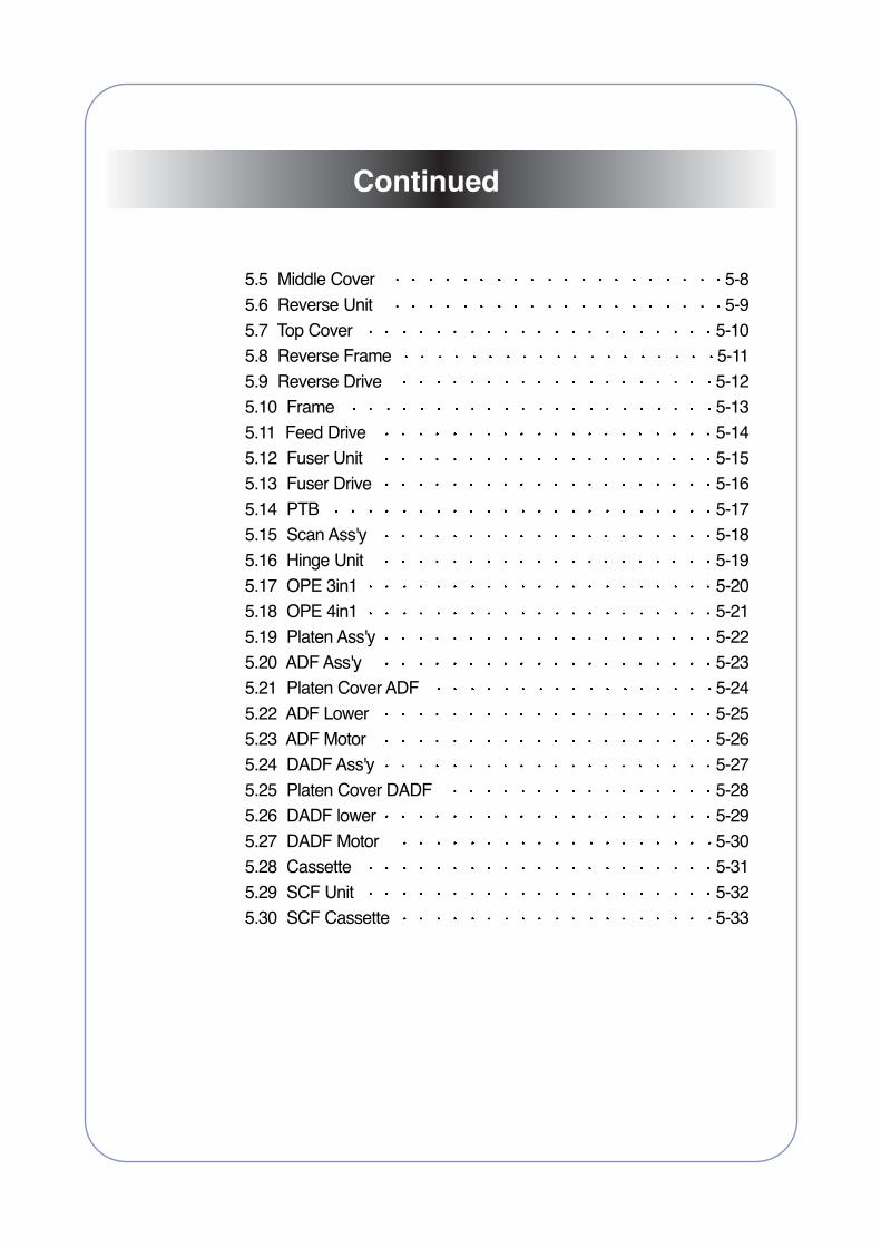
5.5 Middle Cover 5-85.6 Reverse Unit 5-95.7 Top Cover 5-105.8 Reverse Frame 5-115.9 Reverse Drive 5-125.10 Frame 5-135.11 Feed Drive 5-145.12 Fuser Unit 5-155.13 Fuser Drive 5-165.14 PTB 5-175.15 Scan Ass'y 5-185.16 Hinge Unit 5-195.17 OPE 3in1 5-205.18 OPE 4in1 5-215.19 Platen Ass'y 5-225.20 ADF Ass'y 5-235.21 Platen Cover ADF 5-245.22 ADF Lower 5-255.23 ADF Motor 5-265.24 DADF Ass'y 5-275.25 Platen Cover DADF 5-285.26 DADF lower 5-295.27 DADF Motor 5-305.28 Cassette 5-315.29 SCF Unit 5-325.30 SCF Cassette 5-33
Continued
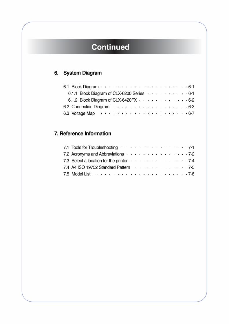
6. System Diagram
6.1 Block Diagram 6-16.1.1 Block Diagram of CLX-6200 Series 6-16.1.2 Block Diagram of CLX-6420FX 6-2
6.2 Connection Diagram 6-36.3 Voltage Map 6-7
7. Reference Information
7.1 Tools for Troubleshooting 7-17.2 Acronyms and Abbreviations 7-27.3 Select a location for the printer 7-47.4 A4 ISO 19752 Standard Pattern 7-57.5 Model List 7-6
Continued
Service Manual
Precautions
1-1 Samsung Electronics
1. PrecautionsIn order to prevent accidents and to prevent damage to the equipment please read the precautions listedbelow carefully before servicing the printer and follow them closely.
1.1 Safety Warning
(1) Only to be serviced by appropriately qualified service engineers.High voltages and lasers inside this product are dangerous. This printer should only be serviced by a suitablytrained and qualified service engineer.
(2) Use only Samsung replacement partsThere are no user serviceable parts inside the printer. Do not make any unauthorized changes or additions to the printer, these could cause the printer to malfunction and create electric shock or fire hazards.
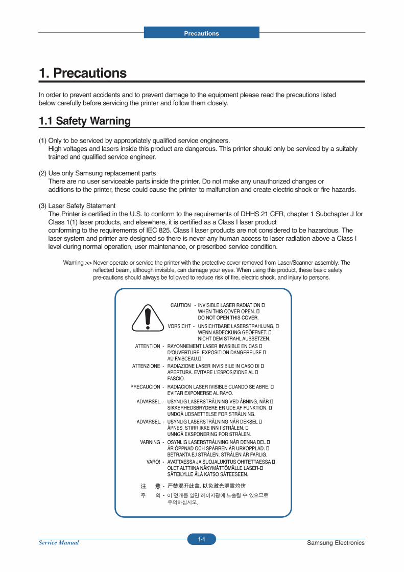
(3) Laser Safety StatementThe Printer is certified in the U.S. to conform to the requirements of DHHS 21 CFR, chapter 1 Subchapter J forClass 1(1) laser products, and elsewhere, it is certified as a Class I laser product conforming to the requirements of IEC 825. Class I laser products are not considered to be hazardous. Thelaser system and printer are designed so there is never any human access to laser radiation above a Class Ilevel during normal operation, user maintenance, or prescribed service condition.
Warning >> Never operate or service the printer with the protective cover removed from Laser/Scanner assembly. Thereflected beam, although invisible, can damage your eyes. When using this product, these basic safety pre-cautions should always be followed to reduce risk of fire, electric shock, and injury to persons.
CAUTION - INVISIBLE LASER RADIATION �WHEN THIS COVER OPEN. �DO NOT OPEN THIS COVER.
VORSICHT - UNSICHTBARE LASERSTRAHLUNG, �WENN ABDECKUNG GEÖFFNET. �NICHT DEM STRAHL AUSSETZEN.
ATTENTION - RAYONNEMENT LASER INVISIBLE EN CAS �D’OUVERTURE. EXPOSITION DANGEREUSE �AU FAISCEAU.�
ATTENZIONE - RADIAZIONE LASER INVISIBILE IN CASO DI �APERTURA. EVITARE L’ESPOSIZIONE AL �FASCIO.
PRECAUCION - RADIACION LASER IVISIBLE CUANDO SE ABRE. �EVITAR EXPONERSE AL RAYO.
ADVARSEL. - USYNLIG LASERSTRÅLNING VED ÅBNING, NÅR �SIKKERHEDSBRYDERE ER UDE AF FUNKTION. �UNDGÅ UDSAETTELSE FOR STRÅLNING.
ADVARSEL. - USYNLIG LASERSTRÅLNING NÅR DEKSEL �ÅPNES. STIRR IKKE INN I STRÅLEN. �UNNGÅ EKSPONERING FOR STRÅLEN.
VARNING - OSYNLIG LASERSTRÅLNING NÄR DENNA DEL �ÄR ÖPPNAD OCH SPÄRREN ÄR URKOPPLAD. �BETRAKTA EJ STRÅLEN. STRÅLEN ÄR FARLIG.
VARO! - AVATTAESSA JA SUOJALUKITUS OHITETTAESSA �OLET ALTTIINA NÄKYMÄTTÖMÄLLE LASER-�SÄTEILYLLE ÄLÄ KATSO SÄTEESEEN.

Service Manual
Precautions
1-2 Samsung Electronics
1.2 Caution for safety
1.2.1 Toxic material
This product contains toxic materials that could cause illness if ingested.
(1) If the LCD control panel is damaged it is possible for the liquid inside to leak. This liquid is toxic. Contact with the skinshould be avoided, wash any splashes from eyes or skin immediately and contact your doctor. If the liquid gets intothe mouth or is swallowed see a doctor immediately.
(2) Please keep toner cartridges away from children. The toner powder contained in the toner cartridge may be harmfuland if swallowed you should contact a doctor.
1.2.2 Electric Shock and Fire Safety Precautions
Failure to follow the following instructions could cause electric shock or potentially cause a fire.
(1) Use only the correct voltage, failure to do so could damage the printer and potentially cause a fire or electricshock.
(2) Use only the power cable supplied with the printer. Use of an incorrectly specified cable could cause the cableto overheat and potentially cause a fire.
(3) Do not overload the power socket, this could lead to overheating of the cables inside the wall and could lead toa fire.
(4) Do not allow water or other liquids to spill into the printer, this can cause electric shock. Do not allow paperclips, pins or other foreign objects to fall into the printer these could cause a short circuit leading to an electricshock or fire hazard..
(5) Never touch the plugs on either end of the power cable with wet hands, this can cause electric shock. Whenservicing the printer remove the power plug from the wall socket.
(6) Use caution when inserting or removing the power connector. The power connector must be inserted com-pletely otherwise a poor contact could cause overheating possibly leading to a fire. When removing the powerconnector grip it firmly and pull.
(7) Take care of the power cable. Do not allow it to become twisted, bent sharply round corners or otherwise damaged. Do not place objects on top of the power cable. If the power cable is damaged it could overheat andcause a fire or exposed cables could cause an electric shock. Replace a damaged power cable immediately,do not reuse or repair the damaged cable. Some chemicals can attack the coating on the power cable, weakening the cover or exposing cables causing fire and shock risks.
(8) Ensure that the power sockets and plugs are not cracked or broken in any way. Any such defects should berepaired immediately. Take care not to cut or damage the power cable or plugs when moving the machine.
(9) Use caution during thunder or lightening storms. Samsung recommend that this machine be disconnected fromthe power source when such weather conditions are expected. Do not touch the machine or the power cord if itis still connected to the wall socket in these weather conditions.
(10) Avoid damp or dusty areas, install the printer in a clean well ventilated location. Do not position the machinenear a humidifier. Damp and dust build up inside the machine can lead to overheating and cause a fire.
(11) Do not position the printer in direct sunlight. This will cause the temperature inside the printer to rise possiblyleading to the printer failing to work properly and in extreme conditions could lead to a fire.
(12) Do not insert any metal objects into the machine through the ventilator fan or other part of the casing, it couldmake contact with a high voltage conductor inside the machine and cause an electric shock.
Service Manual
Precautions
1-3 Samsung Electronics
1.2.3 Handling Precautions
The following instructions are for your own personal safety, to avoid injury and so as not to damage the printer
(1) Ensure the printer is installed on a level surface, capable of supporting its weight. Failure to do so could causethe printer to tip or fall.
(2) The printer contains many rollers, gears and fans. Take great care to ensure that you do not catch your fingers,hair or clothing in any of these rotating devices.
(3) Do not place any small metal objects, containers of water, chemicals or other liquids close to the printer which ifspilled could get into the machine and cause damage or a shock or fire hazard.
(4) Do not install the machine in areas with high dust or moisture levels, beside on open window or close to ahumidifier or heater. Damage could be caused to the printer in such areas.
(5) Do not place candles, burning cigarettes, etc. on the printer, these could cause a fire.
1.2.4 Assembly / Disassembly Precautions
Replace parts carefully, always use Samsung parts. Take care to note the exact location of parts and also
cable routing before dismantling any part of the machine. Ensure all parts and cables are replaced correctly.
Please carry out the following procedures before dismantling the printer or replacing any parts.
(1) Check the contents of the machine memory and make a note of any user settings. These will be erased if themainboard is replaced.
(2) Ensure that power is disconnected before servicing or replacing any electrical parts.
(3) Disconnect printer interface cables and power cables.
(4) Only use approved spare parts. Ensure that part number, product name, any voltage, current or temperaturerating are correct.
(5) When removing or re-fitting any parts do not use excessive force, especially when fitting screws into plastic.
(6) Take care not to drop any small parts into the machine.
(7) Handling of the OPC Drum
- The OPC Drum can be irreparably damaged if it exposed to light.Take care not to expose the OPC Drum either to direct sunlight or to fluorescent or incandescent room lighting. Exposure for as little as 5 mins can damage the surface’s photoconductive properties and will resultin print quality degradation. Take extra care when servicing the printer. Remove the OPC Drum and store it ina black bag or other lightproof container. Take care when working with the covers(especially the top cover)open as light is admitted to the OPC area and can damage the OPC Drum.
- Take care not to scratch the green surface of OPC Drum Unit.If the green surface of the Drum Cartridge is scratched or touched the print quality will be compromised.
Service Manual
Precautions
1-4 Samsung Electronics
1.2.5 Disregarding this warning may cause bodily injury
(1) Be careful with the high temperature part.The fuser unit works at a high temperature. Use caution when working on the printer. Wait for the fuser to cooldown before disassembly.
(2) Do not put finger or hair into the rotating parts.When operating a printer, do not put hand or hair into the rotating parts (Paper feeding entrance, motor, fan,etc.). If do, you can get harm.
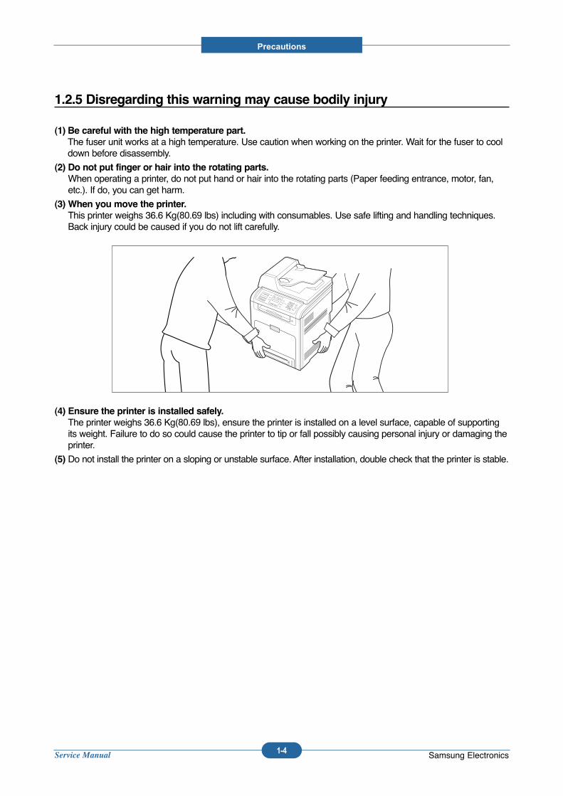
(3) When you move the printer.This printer weighs 36.6 Kg(80.69 lbs) including with consumables. Use safe lifting and handling techniques.Back injury could be caused if you do not lift carefully.
(4) Ensure the printer is installed safely.The printer weighs 36.6 Kg(80.69 lbs), ensure the printer is installed on a level surface, capable of supportingits weight. Failure to do so could cause the printer to tip or fall possibly causing personal injury or damaging theprinter.
(5) Do not install the printer on a sloping or unstable surface. After installation, double check that the printer is stable.

Service Manual
Precautions
1-5 Samsung Electronics
1.3 ESD Precautions
Certain semiconductor devices can be easily damaged by static electricity. Such components are commonly called“Electrostatically Sensitive (ES) Devices”, or ESDs. Examples of typical ESDs are: integrated circuits, some fieldeffect transistors, and semiconductor “chip” components.
The techniques outlined below should be followed to help reduce the incidence of component damage caused bystatic electricity.
Caution >>Be sure no power is applied to the chassis or circuit, and observe all other safety precautions.
1. Immediately before handling a semiconductor component or semiconductor-equipped assembly, drain off anyelectrostatic charge on your body by touching a known earth ground. Alternatively, employ a commercially avail-able wrist strap device, which should be removed for your personal safety reasons prior to applying power to theunit under test.
2. After removing an electrical assembly equipped with ESDs, place the assembly on a conductive surface, such asaluminum or copper foil, or conductive foam, to prevent electrostatic charge buildup in the vicinity of the assem-bly.
3. Use only a grounded tip soldering iron to solder or desolder ESDs.
4. Use only an “anti-static” solder removal device. Some solder removal devices not classified as “anti-static” cangenerate electrical charges sufficient to damage ESDs.
5. Do not use Freon-propelled chemicals. When sprayed, these can generate electrical charges sufficient to dam-age ESDs.
6. Do not remove a replacement ESD from its protective packaging until immediately before installing it. Mostreplacement ESDs are packaged with all leads shorted together by conductive foam, aluminum foil, or a compa-rable conductive material.
7. Immediately before removing the protective shorting material from the leads of a replacement ESD, touch the pro-tective material to the chassis or circuit assembly into which the device will be installed.
8. Maintain continuous electrical contact between the ESD and the assembly into which it will be installed, until com-pletely plugged or soldered into the circuit.
9. Minimize bodily motions when handling unpackaged replacement ESDs. Normal motions, such as the brushingtogether of clothing fabric and lifting one’s foot from a carpeted floor, can generate static electricity sufficient todamage an ESD.
1. Exercise caution when replacing a super capacitor or Lithium battery. There could be a danger of explosion andsubsequent operator injury and/or equipment damage if incorrectly installed.
2. Be sure to replace the battery with the same or equivalent type recommended by the manufacturer.
3. Super capacitor or Lithium batteries contain toxic substances and should not be opened, crushed, or burned fordisposal.
4. Dispose of used batteries according to the manufacture’s instructions.
1.4 Super Capacitor or Lithium Battery Precautions
Service Manual
Product spec and feature
2-1 Samsung Electronics
2. Product specification and feature
2.1 Product Specifications
2.1.1 Product Overview
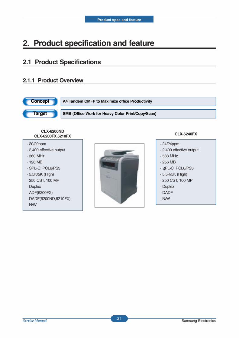
Concept A4 Tandem CMFP to Maximize office Productivity
Target SMB (Office Work for Heavy Color Print/Copy/Scan)
20/20ppm
2,400 effective output
360 MHz
128 MB
SPL-C, PCL6/PS3
5.5K/5K (High)
250 CST, 100 MP
Duplex
ADF(6200FX)
DADF(6200ND,6210FX)
N/W
CLX-6200ND
CLX-6200FX,6210FX
24/24ppm
2,400 effective output
533 MHz
256 MB
PL-C, PCL6/PS3
5.5K/5K (High)
250 CST, 100 MP
Duplex
DADF
N/W
CLX-6240FX
Service Manual
Product spec and feature
2-2 Samsung Electronics
2.1.2 Specifications
Product Specifications are subject to change without notice. See below for product specifications.
2.1.2.1 General Print Engine
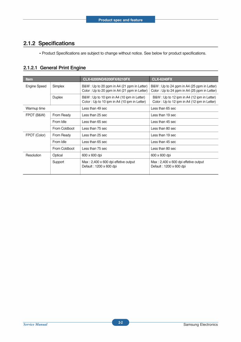
Item CLX-6200ND/6200FX/6210FX CLX-6240FX
Engine Speed Simplex B&W : Up to 20 ppm in A4 (21 ppm in Letter) B&W : Up to 24 ppm in A4 (25 ppm in Letter)Color : Up to 20 ppm in A4 (21 ppm in Letter) Color : Up to 24 ppm in A4 (25 ppm in Letter)
Duplex B&W : Up to 10 ipm in A4 (10 ipm in Letter) B&W : Up to 12 ipm in A4 (12 ipm in Letter) Color : Up to 10 ipm in A4 (10 ipm in Letter) Color : Up to 12 ipm in A4 (12 ipm in Letter)
Warmup time Less than 49 sec Less than 65 sec
FPOT (B&W) From Ready Less than 25 sec Less than 19 sec
From Idle Less than 65 sec Less than 45 sec
From Coldboot Less than 75 sec Less than 80 sec
FPOT (Color) From Ready Less than 25 sec Less than 19 sec
From Idle Less than 65 sec Less than 45 sec
From Coldboot Less than 75 sec Less than 80 sec
Resolution Optical 600 x 600 dpi 600 x 600 dpi
Support Max : 2,400 x 600 dpi effetive output Max : 2,400 x 600 dpi effetive outputDefault : 1200 x 600 dpi Default : 1200 x 600 dpi
Service Manual
Product spec and feature
2-3 Samsung Electronics
2.1.2.2 Controller & S/W
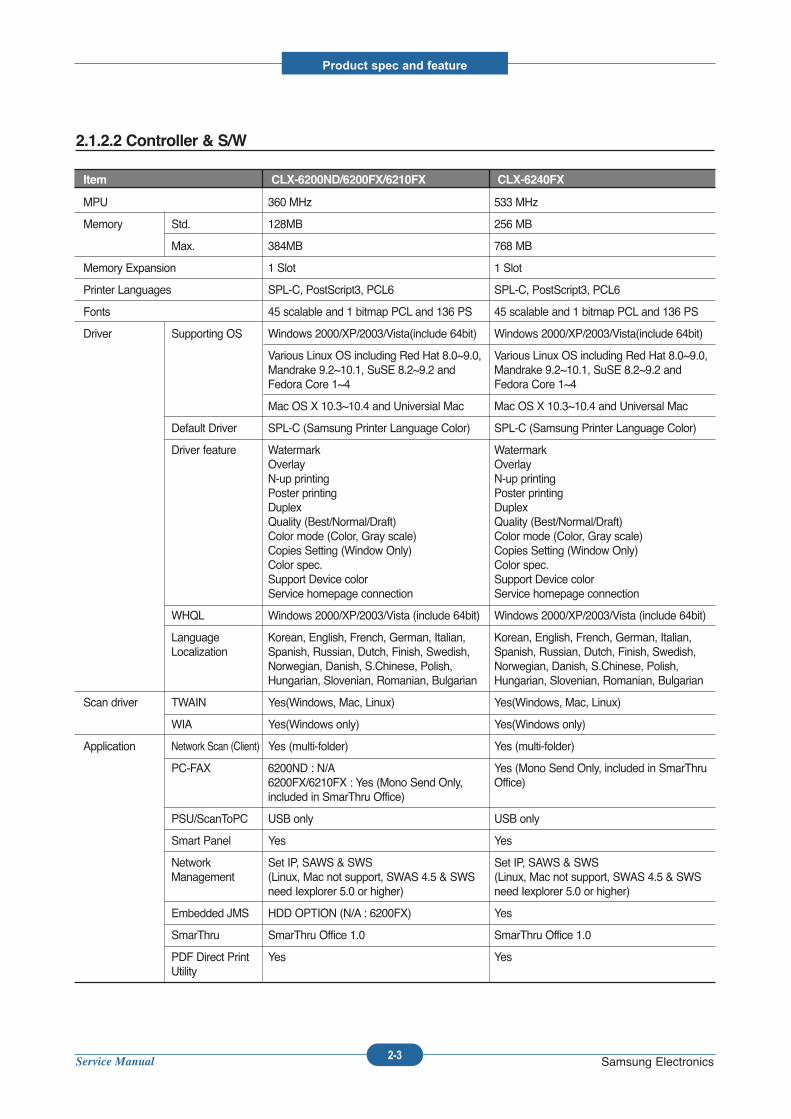
Item CLX-6200ND/6200FX/6210FX CLX-6240FX
MPU 360 MHz 533 MHz
Memory Std. 128MB 256 MB
Max. 384MB 768 MB
Memory Expansion 1 Slot 1 Slot
Printer Languages SPL-C, PostScript3, PCL6 SPL-C, PostScript3, PCL6
Fonts 45 scalable and 1 bitmap PCL and 136 PS 45 scalable and 1 bitmap PCL and 136 PS
Driver Supporting OS Windows 2000/XP/2003/Vista(include 64bit) Windows 2000/XP/2003/Vista(include 64bit)
Various Linux OS including Red Hat 8.0~9.0, Various Linux OS including Red Hat 8.0~9.0, Mandrake 9.2~10.1, SuSE 8.2~9.2 and Mandrake 9.2~10.1, SuSE 8.2~9.2 and Fedora Core 1~4 Fedora Core 1~4
Mac OS X 10.3~10.4 and Universial Mac Mac OS X 10.3~10.4 and Universal Mac
Default Driver SPL-C (Samsung Printer Language Color) SPL-C (Samsung Printer Language Color)
Driver feature Watermark WatermarkOverlay OverlayN-up printing N-up printingPoster printing Poster printingDuplex DuplexQuality (Best/Normal/Draft) Quality (Best/Normal/Draft)Color mode (Color, Gray scale) Color mode (Color, Gray scale)Copies Setting (Window Only) Copies Setting (Window Only)Color spec. Color spec.Support Device color Support Device colorService homepage connection Service homepage connection
WHQL Windows 2000/XP/2003/Vista (include 64bit) Windows 2000/XP/2003/Vista (include 64bit)
Language Korean, English, French, German, Italian, Korean, English, French, German, Italian, Localization Spanish, Russian, Dutch, Finish, Swedish, Spanish, Russian, Dutch, Finish, Swedish,
Norwegian, Danish, S.Chinese, Polish, Norwegian, Danish, S.Chinese, Polish, Hungarian, Slovenian, Romanian, Bulgarian Hungarian, Slovenian, Romanian, Bulgarian
Scan driver TWAIN Yes(Windows, Mac, Linux) Yes(Windows, Mac, Linux)
WIA Yes(Windows only) Yes(Windows only)
Application Network Scan (Client) Yes (multi-folder) Yes (multi-folder)
PC-FAX 6200ND : N/A Yes (Mono Send Only, included in SmarThru6200FX/6210FX : Yes (Mono Send Only, Office)included in SmarThru Office)
PSU/ScanToPC USB only USB only
Smart Panel Yes Yes
Network Set IP, SAWS & SWS Set IP, SAWS & SWSManagement (Linux, Mac not support, SWAS 4.5 & SWS (Linux, Mac not support, SWAS 4.5 & SWS
need Iexplorer 5.0 or higher) need Iexplorer 5.0 or higher)
Embedded JMS HDD OPTION (N/A : 6200FX) Yes
SmarThru SmarThru Office 1.0 SmarThru Office 1.0
PDF Direct Print Yes YesUtility
Service Manual
Product spec and feature
2-4 Samsung Electronics
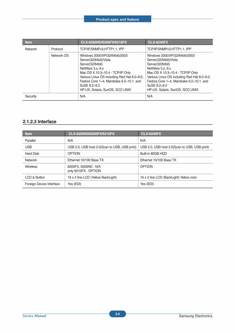
2.1.2.3 Interface
Item CLX-6200ND/6200FX/6210FX CLX-6240FX
Parallel N/A N/A
USB USB 2.0, USB host 2.0(Scan to USB, USB print) USB 2.0, USB host 2.0(Scan to USB, USB print)
Hard Disk OPTION Built-in 80GB HDD
Network Ethernet 10/100 Base TX Ethernet 10/100 Base TX
Wireless 6200FX, 6200ND : N/A OPTIONonly 6210FX : OPTION
LCD & Button 16 x 2 line LCD (Yellow BackLight) 16 x 2 line LCD (BackLight) Yellow color
Foreign Device Interface Yes (EDI) Yes (EDI)
Item CLX-6200ND/6200FX/6210FX CLX-6240FX
Network Protocol TCP/IP,SNMPv3,HTTP1.1, IPP TCP/IP,SNMPv3,HTTP1.1, IPP
Network OS Windows 2000/XP(32/64bit)/2003 Windows 2000/XP(32/64bit)/2003 Server(32/64bit)/Vista Server(32/64bit)/VistaServer(32/64bit) Server(32/64bit) NetWare 5.x, 6.x NetWare 5.x, 6.x Mac OS X 10.3~10.4 - TCP/IP Only Mac OS X 10.3~10.4 - TCP/IP OnlyVarious Linux OS including Red Hat 8.0~9.0, Various Linux OS including Red Hat 8.0~9.0, Fedora Core 1~4, Mandrake 9.2~10.1, and Fedora Core 1~4, Mandrake 9.2~10.1, and SuSE 8.2~9.2 SuSE 8.2~9.2HP-UX, Solaris, SunOS, SCO UNIX HP-UX, Solaris, SunOS, SCO UNIX
Security N/A N/A
Service Manual
Product spec and feature
2-5 Samsung Electronics
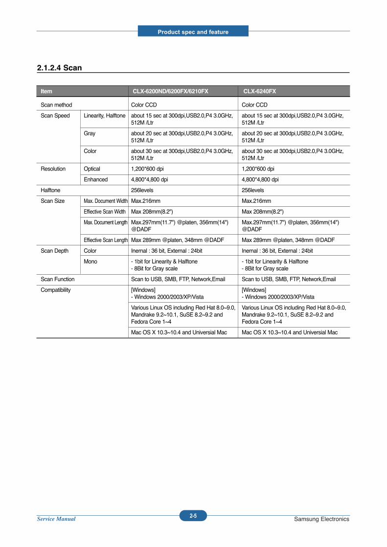
Scan method Color CCD Color CCD
Scan Speed Linearity, Halftone about 15 sec at 300dpi,USB2.0,P4 3.0GHz, about 15 sec at 300dpi,USB2.0,P4 3.0GHz,512M /Ltr 512M /Ltr
Gray about 20 sec at 300dpi,USB2.0,P4 3.0GHz, about 20 sec at 300dpi,USB2.0,P4 3.0GHz,512M /Ltr 512M /Ltr
Color about 30 sec at 300dpi,USB2.0,P4 3.0GHz, about 30 sec at 300dpi,USB2.0,P4 3.0GHz,512M /Ltr 512M /Ltr
Resolution Optical 1,200*600 dpi 1,200*600 dpi
Enhanced 4,800*4,800 dpi 4,800*4,800 dpi
Halftone 256levels 256levels
Scan Size Max. Document Width Max.216mm Max.216mm
Effiective Scan Width Max 208mm(8.2") Max 208mm(8.2")
Max. Document Length Max.297mm(11.7") @platen, 356mm(14") Max.297mm(11.7") @platen, 356mm(14") @DADF @DADF
Effiective Scan Length Max 289mm @platen, 348mm @DADF Max 289mm @platen, 348mm @DADF
Scan Depth Color Inernal : 36 bit, External : 24bit Inernal : 36 bit, External : 24bit
Mono - 1bit for Linearity & Halftone - 1bit for Linearity & Halftone- 8Bit for Gray scale - 8Bit for Gray scale
Scan Function Scan to USB, SMB, FTP, Network,Email Scan to USB, SMB, FTP, Network,Email
Compatibility [Windows] [Windows] - Windows 2000/2003/XP/Vista - Windows 2000/2003/XP/Vista
Various Linux OS including Red Hat 8.0~9.0, Various Linux OS including Red Hat 8.0~9.0, Mandrake 9.2~10.1, SuSE 8.2~9.2 and Mandrake 9.2~10.1, SuSE 8.2~9.2 andFedora Core 1~4 Fedora Core 1~4
Mac OS X 10.3~10.4 and Universial Mac Mac OS X 10.3~10.4 and Universial Mac
Item CLX-6200ND/6200FX/6210FX CLX-6240FX
2.1.2.4 Scan
Service Manual
Product spec and feature
2-6 Samsung Electronics
2.1.2.5 Copy
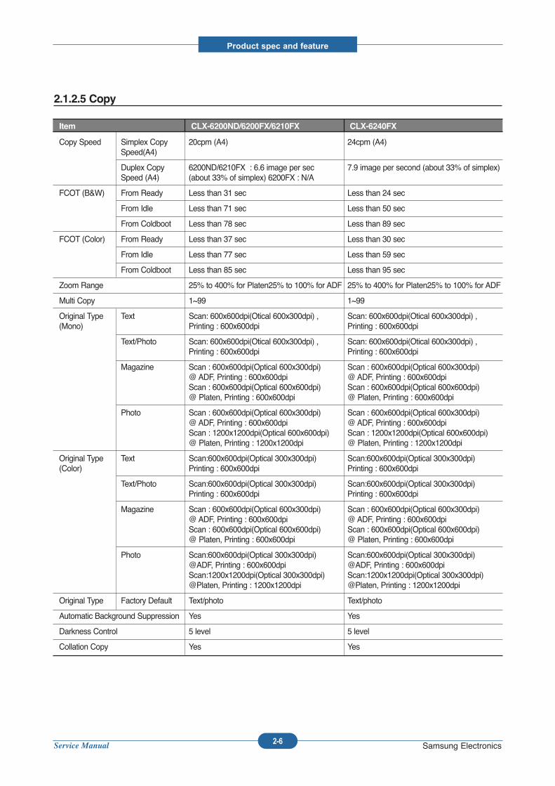
Item CLX-6200ND/6200FX/6210FX CLX-6240FX
Copy Speed Simplex Copy 20cpm (A4) 24cpm (A4)Speed(A4)
Duplex Copy 6200ND/6210FX : 6.6 image per sec 7.9 image per second (about 33% of simplex)Speed (A4) (about 33% of simplex) 6200FX : N/A
FCOT (B&W) From Ready Less than 31 sec Less than 24 sec
From Idle Less than 71 sec Less than 50 sec
From Coldboot Less than 78 sec Less than 89 sec
FCOT (Color) From Ready Less than 37 sec Less than 30 sec
From Idle Less than 77 sec Less than 59 sec
From Coldboot Less than 85 sec Less than 95 sec
Zoom Range 25% to 400% for Platen25% to 100% for ADF 25% to 400% for Platen25% to 100% for ADF
Multi Copy 1~99 1~99
Original Type Text Scan: 600x600dpi(Otical 600x300dpi) , Scan: 600x600dpi(Otical 600x300dpi) , (Mono) Printing : 600x600dpi Printing : 600x600dpi
Text/Photo Scan: 600x600dpi(Otical 600x300dpi) , Scan: 600x600dpi(Otical 600x300dpi) , Printing : 600x600dpi Printing : 600x600dpi
Magazine Scan : 600x600dpi(Optical 600x300dpi) Scan : 600x600dpi(Optical 600x300dpi) @ ADF, Printing : 600x600dpi @ ADF, Printing : 600x600dpiScan : 600x600dpi(Optical 600x600dpi) Scan : 600x600dpi(Optical 600x600dpi) @ Platen, Printing : 600x600dpi @ Platen, Printing : 600x600dpi
Photo Scan : 600x600dpi(Optical 600x300dpi) Scan : 600x600dpi(Optical 600x300dpi) @ ADF, Printing : 600x600dpi @ ADF, Printing : 600x600dpiScan : 1200x1200dpi(Optical 600x600dpi) Scan : 1200x1200dpi(Optical 600x600dpi) @ Platen, Printing : 1200x1200dpi @ Platen, Printing : 1200x1200dpi
Original Type Text Scan:600x600dpi(Optical 300x300dpi) Scan:600x600dpi(Optical 300x300dpi) (Color) Printing : 600x600dpi Printing : 600x600dpi
Text/Photo Scan:600x600dpi(Optical 300x300dpi) Scan:600x600dpi(Optical 300x300dpi) Printing : 600x600dpi Printing : 600x600dpi
Magazine Scan : 600x600dpi(Optical 600x300dpi) Scan : 600x600dpi(Optical 600x300dpi) @ ADF, Printing : 600x600dpi @ ADF, Printing : 600x600dpiScan : 600x600dpi(Optical 600x600dpi) Scan : 600x600dpi(Optical 600x600dpi) @ Platen, Printing : 600x600dpi @ Platen, Printing : 600x600dpi
Photo Scan:600x600dpi(Optical 300x300dpi) Scan:600x600dpi(Optical 300x300dpi) @ADF, Printing : 600x600dpi @ADF, Printing : 600x600dpiScan:1200x1200dpi(Optical 300x300dpi) Scan:1200x1200dpi(Optical 300x300dpi) @Platen, Printing : 1200x1200dpi @Platen, Printing : 1200x1200dpi
Original Type Factory Default Text/photo Text/photo
Automatic Background Suppression Yes Yes
Darkness Control 5 level 5 level
Collation Copy Yes Yes
Service Manual
Product spec and feature
2-7 Samsung Electronics
Item CLX-6200ND/6200FX/6210FX CLX-6240FX
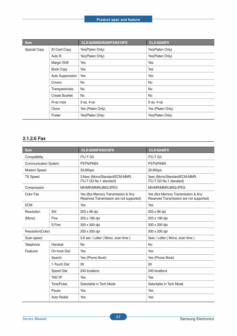
Special Copy ID Card Copy Yes(Platen Only) Yes(Platen Only)
Auto fit Yes(Platen Only) Yes(Platen Only)
Margin Shift Yes Yes
Book Copy Yes Yes
Auto Suppression Yes Yes
Covers No No
Transparencies No No
Create Booklet No No
N-up copy 2-up, 4-up 2-up, 4-up
Clone Yes (Platen Only) Yes (Platen Only)
Poster Yes(Platen Only) Yes(Platen Only)
2.1.2.6 Fax
Item CLX-6200FX/6210FX CLX-6240FX
Compatibility ITU-T G3 ITU-T G3
Communication System PSTN/PABX PSTN/PABX
Modem Speed 33.6Kbps 33.6Kbps
TX Speed 3.6sec (Mono/Standard/ECM-MMR, 3sec (Mono/Standard/ECM-MMR,ITU-T G3 No.1 standard) ITU-T G3 No.1 standard)
Compression MH/MR/MMR/JBIG/JPEG MH/MR/MMR/JBIG/JPEG
Color Fax Yes (But Memory Transmission & Any Yes (But Memory Transmission & Any Reserved Transmission are not supported) Reserved Transmission are not supported)
ECM Yes Yes
Resolution Std 203 x 98 dpi 203 x 98 dpi
(Mono) Fine 203 x 196 dpi 203 x 196 dpi
S.Fine 300 x 300 dpi 300 x 300 dpi
Resolution(Color) 200 x 200 dpi 200 x 200 dpi
Scan speed 3.6 sec / Letter ( Mono, scan time ) 3sec / Letter ( Mono, scan time )
Telephone Handset No No
Features On hook Dial Yes Yes
Search Yes (Phone Book) Yes (Phone Book)
1-Touch Dial 30 30
Speed Dial 240 locations 240 locations
TAD I/F Yes Yes
Tone/Pulse Selectable in Tech Mode Selectable in Tech Mode
Pause Yes Yes
Auto Redial Yes Yes
Service Manual
Product spec and feature
2-8 Samsung Electronics
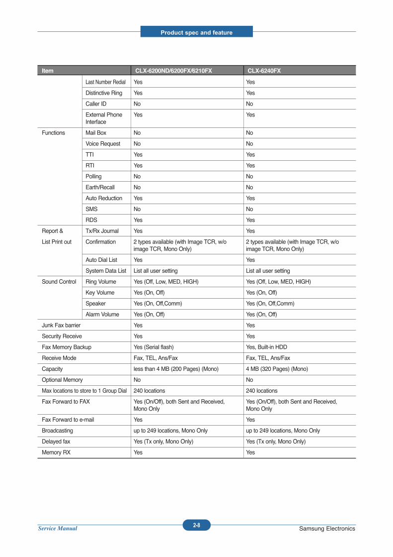
Item CLX-6200ND/6200FX/6210FX CLX-6240FX
Last Number Redial Yes Yes
Distinctive Ring Yes Yes
Caller ID No No
External Phone Yes YesInterface
Functions Mail Box No No
Voice Request No No
TTI Yes Yes
RTI Yes Yes
Polling No No
Earth/Recall No No
Auto Reduction Yes Yes
SMS No No
RDS Yes Yes
Report & Tx/Rx Journal Yes Yes
List Print out Confirmation 2 types available (with Image TCR, w/o 2 types available (with Image TCR, w/oimage TCR, Mono Only) image TCR, Mono Only)
Auto Dial List Yes Yes
System Data List List all user setting List all user setting
Sound Control Ring Volume Yes (Off, Low, MED, HIGH) Yes (Off, Low, MED, HIGH)
Key Volume Yes (On, Off) Yes (On, Off)
Speaker Yes (On, Off,Comm) Yes (On, Off,Comm)
Alarm Volume Yes (On, Off) Yes (On, Off)
Junk Fax barrier Yes Yes
Security Receive Yes Yes
Fax Memory Backup Yes (Serial flash) Yes, Built-in HDD
Receive Mode Fax, TEL, Ans/Fax Fax, TEL, Ans/Fax
Capacity less than 4 MB (200 Pages) (Mono) 4 MB (320 Pages) (Mono)
Optional Memory No No
Max locations to store to 1 Group Dial 240 locations 240 locations
Fax Forward to FAX Yes (On/Off), both Sent and Received, Yes (On/Off), both Sent and Received, Mono Only Mono Only
Fax Forward to e-mail Yes Yes
Broadcasting up to 249 locations, Mono Only up to 249 locations, Mono Only
Delayed fax Yes (Tx only, Mono Only) Yes (Tx only, Mono Only)
Memory RX Yes Yes
Service Manual
Product spec and feature
2-9 Samsung Electronics
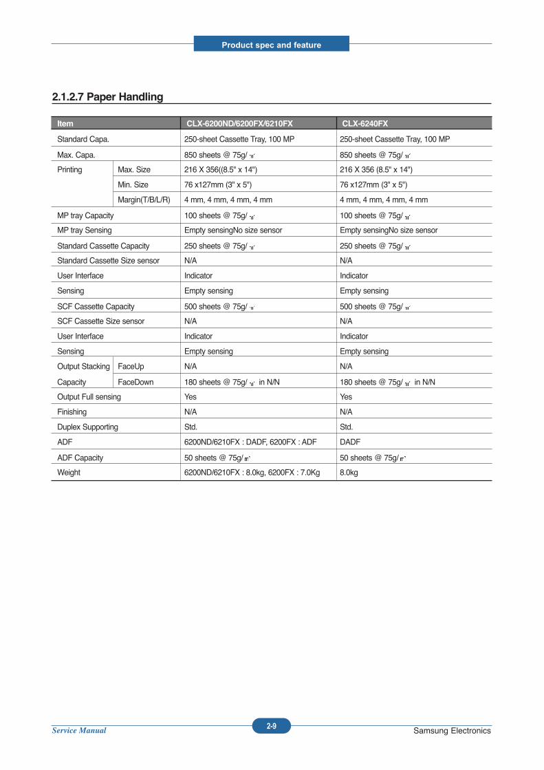
2.1.2.7 Paper Handling
Item CLX-6200ND/6200FX/6210FX CLX-6240FX
Standard Capa. 250-sheet Cassette Tray, 100 MP 250-sheet Cassette Tray, 100 MP
Max. Capa. 850 sheets @ 75g/ 850 sheets @ 75g/
Printing Max. Size 216 X 356((8.5" x 14") 216 X 356 (8.5" x 14")
Min. Size 76 x127mm (3" x 5") 76 x127mm (3" x 5")
Margin(T/B/L/R) 4 mm, 4 mm, 4 mm, 4 mm 4 mm, 4 mm, 4 mm, 4 mm
MP tray Capacity 100 sheets @ 75g/ 100 sheets @ 75g/
MP tray Sensing Empty sensingNo size sensor Empty sensingNo size sensor
Standard Cassette Capacity 250 sheets @ 75g/ 250 sheets @ 75g/
Standard Cassette Size sensor N/A N/A
User Interface Indicator Indicator
Sensing Empty sensing Empty sensing
SCF Cassette Capacity 500 sheets @ 75g/ 500 sheets @ 75g/
SCF Cassette Size sensor N/A N/A
User Interface Indicator Indicator
Sensing Empty sensing Empty sensing
Output Stacking FaceUp N/A N/A
Capacity FaceDown 180 sheets @ 75g/ in N/N 180 sheets @ 75g/ in N/N
Output Full sensing Yes Yes
Finishing N/A N/A
Duplex Supporting Std. Std.
ADF 6200ND/6210FX : DADF, 6200FX : ADF DADF
ADF Capacity 50 sheets @ 75g/ 50 sheets @ 75g/
Weight 6200ND/6210FX : 8.0kg, 6200FX : 7.0Kg 8.0kg
Service Manual
Product spec and feature
2-10 Samsung Electronics
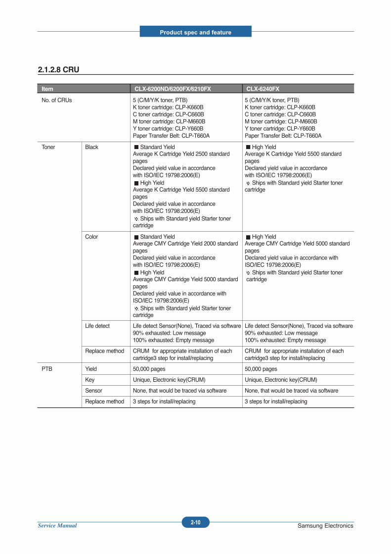
2.1.2.8 CRU
Item CLX-6200ND/6200FX/6210FX CLX-6240FX
No. of CRUs 5 (C/M/Y/K toner, PTB) 5 (C/M/Y/K toner, PTB)K toner cartridge: CLP-K660B K toner cartridge: CLP-K660BC toner cartridge: CLP-C660B C toner cartridge: CLP-C660BM toner cartridge: CLP-M660B M toner cartridge: CLP-M660BY toner cartridge: CLP-Y660B Y toner cartridge: CLP-Y660BPaper Transfer Belt: CLP-T660A Paper Transfer Belt: CLP-T660A
Toner Black Standard Yield High YieldAverage K Cartridge Yield 2500 standard Average K Cartridge Yield 5500 standardpages pages Declared yield value in accordance Declared yield value in accordance with ISO/IEC 19798:2006(E) with ISO/IEC 19798:2006(E)High Yield Ships with Standard yield Starter toner
Average K Cartridge Yield 5500 standard cartridgepages Declared yield value in accordance with ISO/IEC 19798:2006(E)Ships with Standard yield Starter toner
cartridge
Color Standard Yield High YieldAverage CMY Cartridge Yield 2000 standard Average CMY Cartridge Yield 5000 standard pages pagesDeclared yield value in accordance Declared yield value in accordance with with ISO/IEC 19798:2006(E) ISO/IEC 19798:2006(E)High Yield Ships with Standard yield Starter toner
Average CMY Cartridge Yield 5000 standard cartridgepages Declared yield value in accordance with ISO/IEC 19798:2006(E)Ships with Standard yield Starter toner
cartridge
Life detect Life detect Sensor(None), Traced via software Life detect Sensor(None), Traced via software 90% exhausted: Low message 90% exhausted: Low message 100% exhausted: Empty message 100% exhausted: Empty message
Replace method CRUM for appropriate installation of each CRUM for appropriate installation of each cartridge3 step for install/replacing cartridge3 step for install/replacing
PTB Yield 50,000 pages 50,000 pages
Key Unique, Electronic key(CRUM) Unique, Electronic key(CRUM)
Sensor None, that would be traced via software None, that would be traced via software
Replace method 3 steps for install/replacing 3 steps for install/replacing
Service Manual
Product spec and feature
2-11 Samsung Electronics
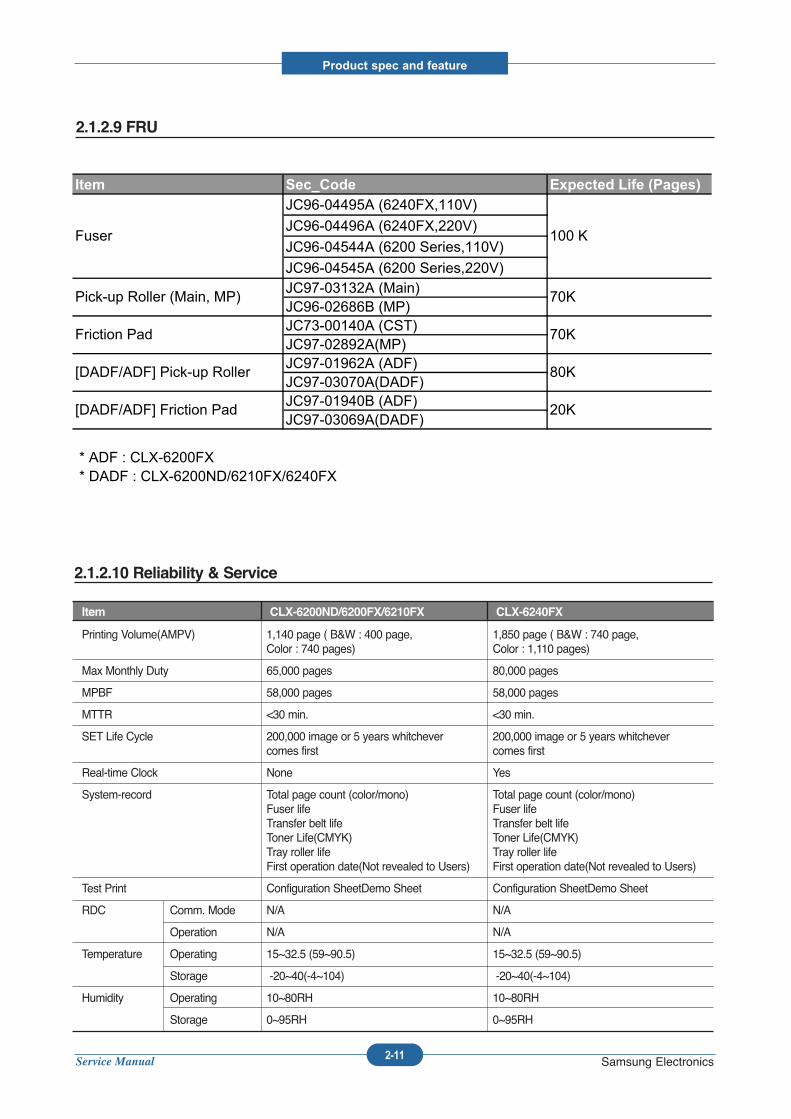
2.1.2.9 FRU
2.1.2.10 Reliability & Service
Item CLX-6200ND/6200FX/6210FX CLX-6240FX
Printing Volume(AMPV) 1,140 page ( B&W : 400 page, 1,850 page ( B&W : 740 page, Color : 740 pages) Color : 1,110 pages)
Max Monthly Duty 65,000 pages 80,000 pages
MPBF 58,000 pages 58,000 pages
MTTR <30 min. <30 min.
SET Life Cycle 200,000 image or 5 years whitchever 200,000 image or 5 years whitchevercomes first comes first
Real-time Clock None Yes
System-record Total page count (color/mono) Total page count (color/mono)Fuser life Fuser lifeTransfer belt life Transfer belt lifeToner Life(CMYK) Toner Life(CMYK)Tray roller life Tray roller lifeFirst operation date(Not revealed to Users) First operation date(Not revealed to Users)
Test Print Configuration SheetDemo Sheet Configuration SheetDemo Sheet
RDC Comm. Mode N/A N/A
Operation N/A N/A
Temperature Operating 15~32.5 (59~90.5) 15~32.5 (59~90.5)
Storage -20~40(-4~104) -20~40(-4~104)
Humidity Operating 10~80RH 10~80RH
Storage 0~95RH 0~95RH
Item Sec_Code Expected Life (Pages)JC96-04495A (6240FX,110V)JC96-04496A (6240FX,220V)JC96-04544A (6200 Series,110V)JC96-04545A (6200 Series,220V)JC97-03132A (Main)JC96-02686B (MP)JC73-00140A (CST)JC97-02892A(MP)JC97-01962A (ADF)JC97-03070A(DADF)JC97-01940B (ADF)JC97-03069A(DADF)
* ADF : CLX-6200FX * DADF : CLX-6200ND/6210FX/6240FX
100 KFuser
Friction Pad
Pick-up Roller (Main, MP) 70K
70K
[DADF/ADF] Pick-up Roller 80K
20K[DADF/ADF] Friction Pad
Service Manual
Product spec and feature
2-12 Samsung Electronics
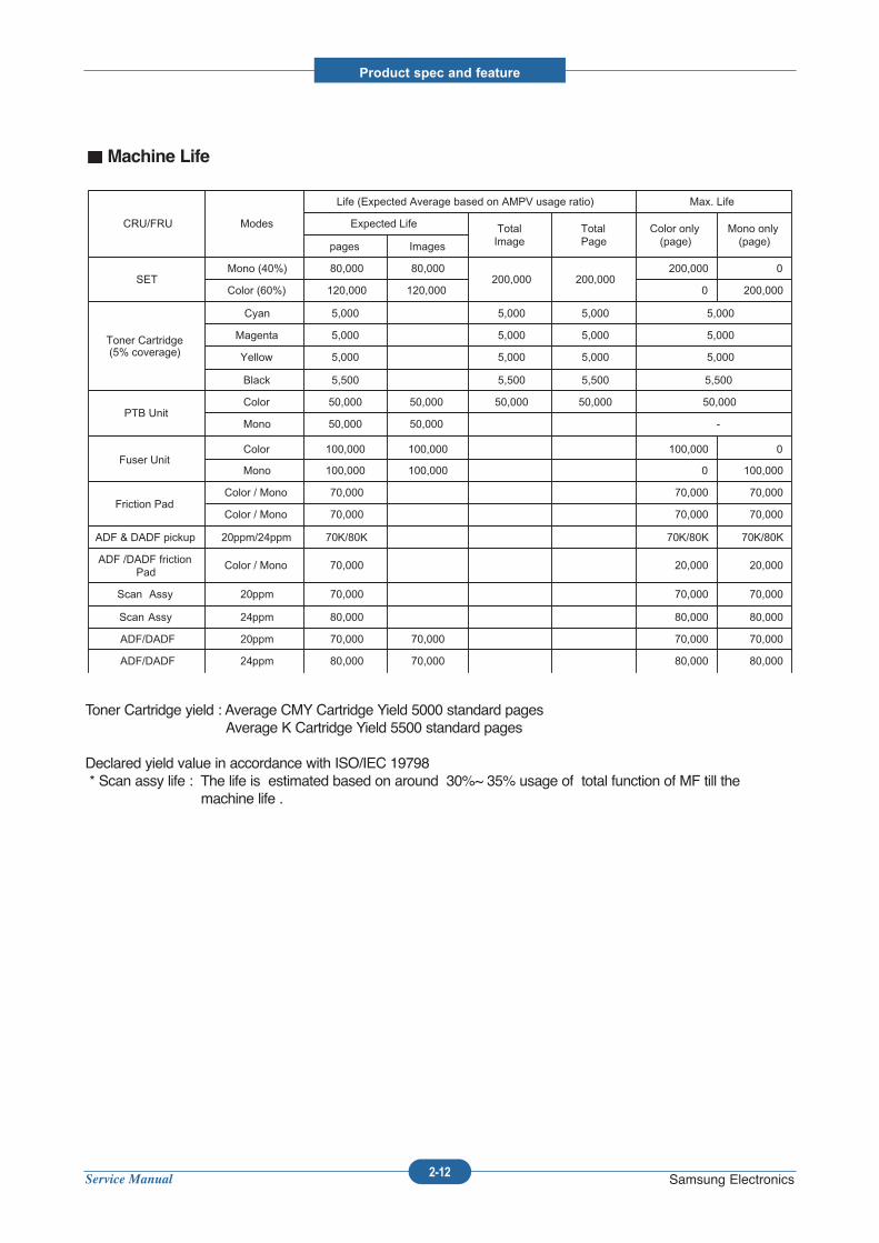
Machine Life
Toner Cartridge yield : Average CMY Cartridge Yield 5000 standard pagesAverage K Cartridge Yield 5500 standard pages
Declared yield value in accordance with ISO/IEC 19798* Scan assy life : The life is estimated based on around 30%~ 35% usage of total function of MF till the
machine life .
80,00080,00070,00080,00024ppmADF/DADF
70,00070,00070,00070,00020ppmADF/DADF
80,00080,00080,00024ppmScan Assy
70,00070,00070,00020ppmScan Assy
20,00020,00070,000Color / MonoADF /DADF friction Pad
70K/80K70K/80K70K/80K20ppm/24ppmADF & DADF pickup
70,00070,00070,000Color / MonoFriction Pad
70,000 70,000 70,000Color / Mono
100,000 0 100,000100,000 Mono
0 100,000 100,000100,000 Color Fuser Unit
-50,000 50,000 Mono
50,000 50,000 50,000 50,000 50,000 ColorPTB Unit
5,500 5,500 5,500 5,500 Black
5,000 5,000 5,000 5,000 Yellow
5,000 5,000 5,000 5,000 Magenta
5,000 5,000 5,000 5,000 Cyan
Toner Cartridge(5% coverage)
200,000 0 120,000 120,000Color (60%)
0 200,000 200,000 200,000
80,00080,000Mono (40%)SET
Imagespages
Mono only(page)
Color only(page)
TotalPage
Total Image
Expected Life
Max. LifeLife (Expected Average based on AMPV usage ratio)
ModesCRU/FRU
Service Manual
Product spec and feature
2-13 Samsung Electronics
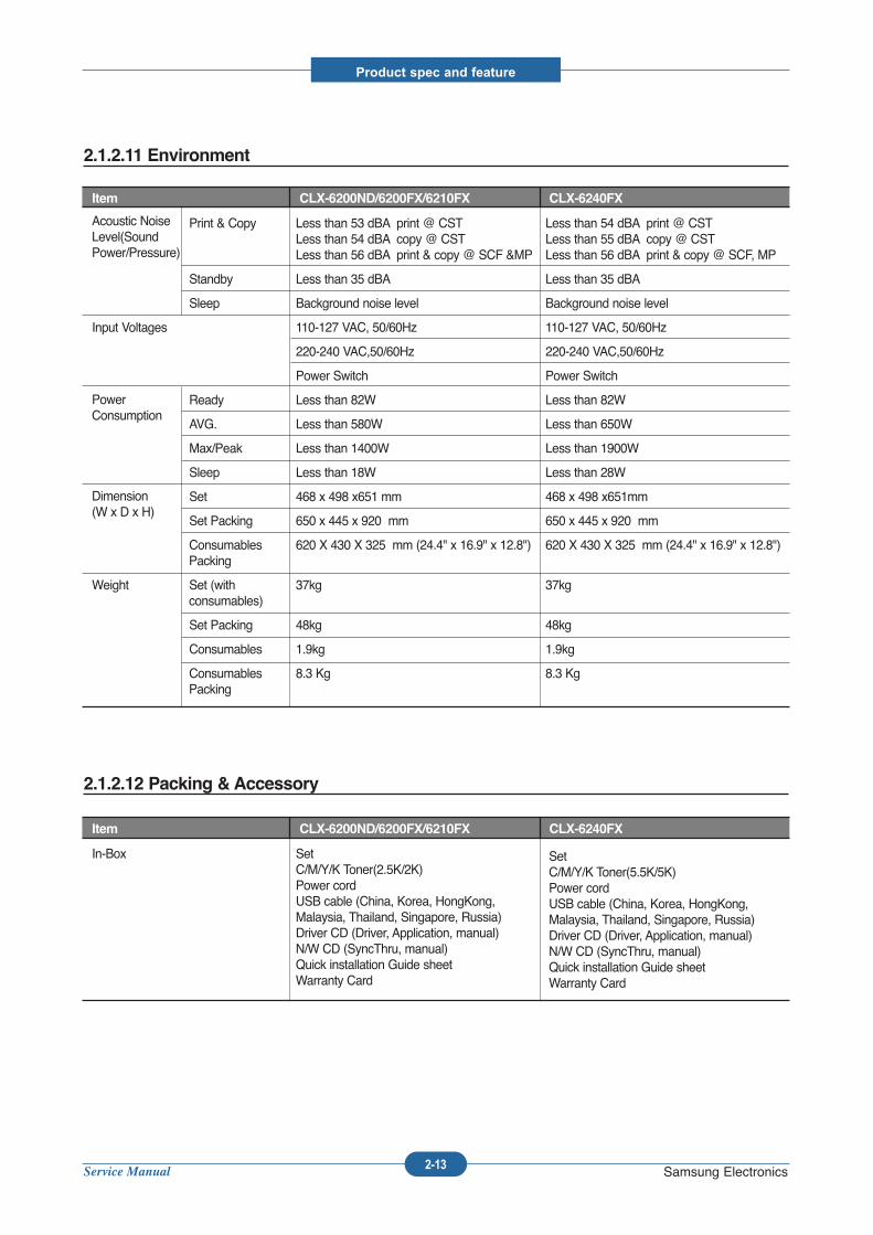
2.1.2.11 Environment
Item CLX-6200ND/6200FX/6210FX CLX-6240FX
Print & Copy Less than 53 dBA print @ CST Less than 54 dBA print @ CSTLess than 54 dBA copy @ CST Less than 55 dBA copy @ CSTLess than 56 dBA print & copy @ SCF &MP Less than 56 dBA print & copy @ SCF, MP
Standby Less than 35 dBA Less than 35 dBA
Sleep Background noise level Background noise level
Input Voltages 110-127 VAC, 50/60Hz 110-127 VAC, 50/60Hz
220-240 VAC,50/60Hz 220-240 VAC,50/60Hz
Power Switch Power Switch
Ready Less than 82W Less than 82W
AVG. Less than 580W Less than 650W
Max/Peak Less than 1400W Less than 1900W
Sleep Less than 18W Less than 28W
Set 468 x 498 x651 mm 468 x 498 x651mm
Set Packing 650 x 445 x 920 mm 650 x 445 x 920 mm
Consumables 620 X 430 X 325 mm (24.4" x 16.9" x 12.8") 620 X 430 X 325 mm (24.4" x 16.9" x 12.8")Packing
Weight Set (with 37kg 37kgconsumables)
Set Packing 48kg 48kg
Consumables 1.9kg 1.9kg
Consumables 8.3 Kg 8.3 KgPacking
Acoustic NoiseLevel(SoundPower/Pressure)
PowerConsumption
Dimension(W x D x H)
2.1.2.12 Packing & Accessory
Item CLX-6200ND/6200FX/6210FX CLX-6240FX
In-Box SetC/M/Y/K Toner(2.5K/2K)Power cordUSB cable (China, Korea, HongKong, Malaysia, Thailand, Singapore, Russia)Driver CD (Driver, Application, manual)N/W CD (SyncThru, manual)Quick installation Guide sheetWarranty Card
SetC/M/Y/K Toner(5.5K/5K)Power cordUSB cable (China, Korea, HongKong, Malaysia, Thailand, Singapore, Russia)Driver CD (Driver, Application, manual)N/W CD (SyncThru, manual)Quick installation Guide sheetWarranty Card
Service Manual
Product spec and feature
2-14 Samsung Electronics
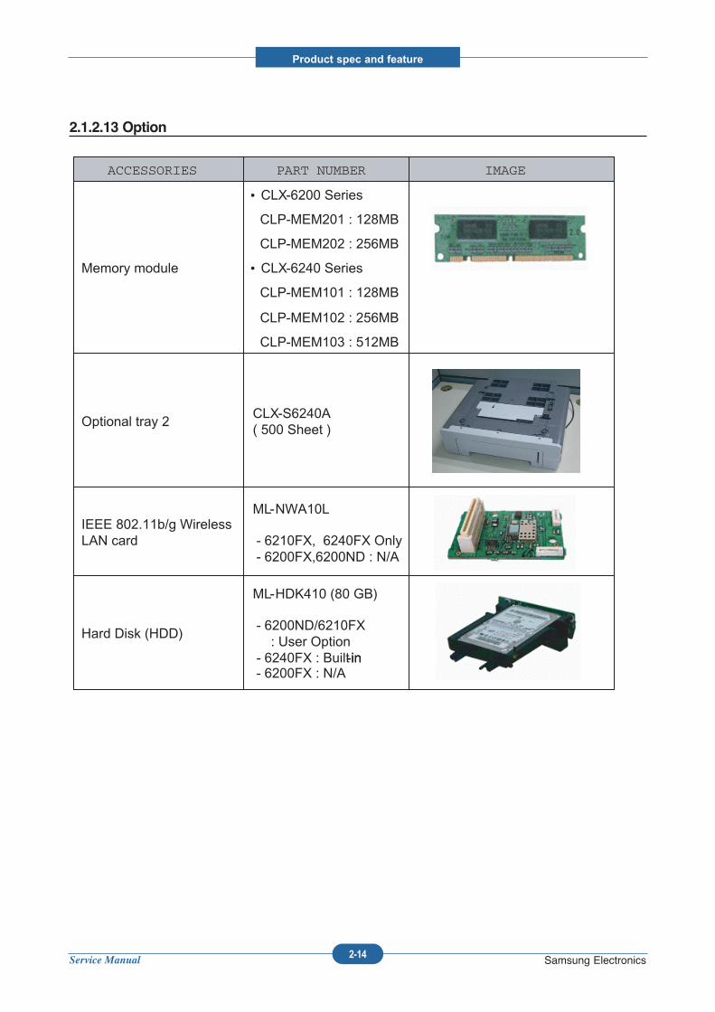
2.1.2.13 Option
ML-HDK410 (80 GB)
- 6200ND/6210FX : User Option
- 6240FX : Built-in- 6200FX : N/A
Hard Disk (HDD)
ML-NWA10L
- 6210FX, 6240FX Only- 6200FX,6200ND : N/A
IEEE 802.11b/g WirelessLAN card
CLX-S6240A ( 500 Sheet )
Optional tray 2
CLP-MEM103 : 512MB
CLP-MEM102 : 256MB
CLP-MEM101 : 128MB
CLX-6240 Series
CLP-MEM202 : 256MB
CLP-MEM201 : 128MB
CLX-6200 Series
Memory module
IMAGEPART NUMBERACCESSORIES
-in
IMAGEPART NUMBERACCESSORIES
Service Manual
Product spec and feature
2-15 Samsung Electronics
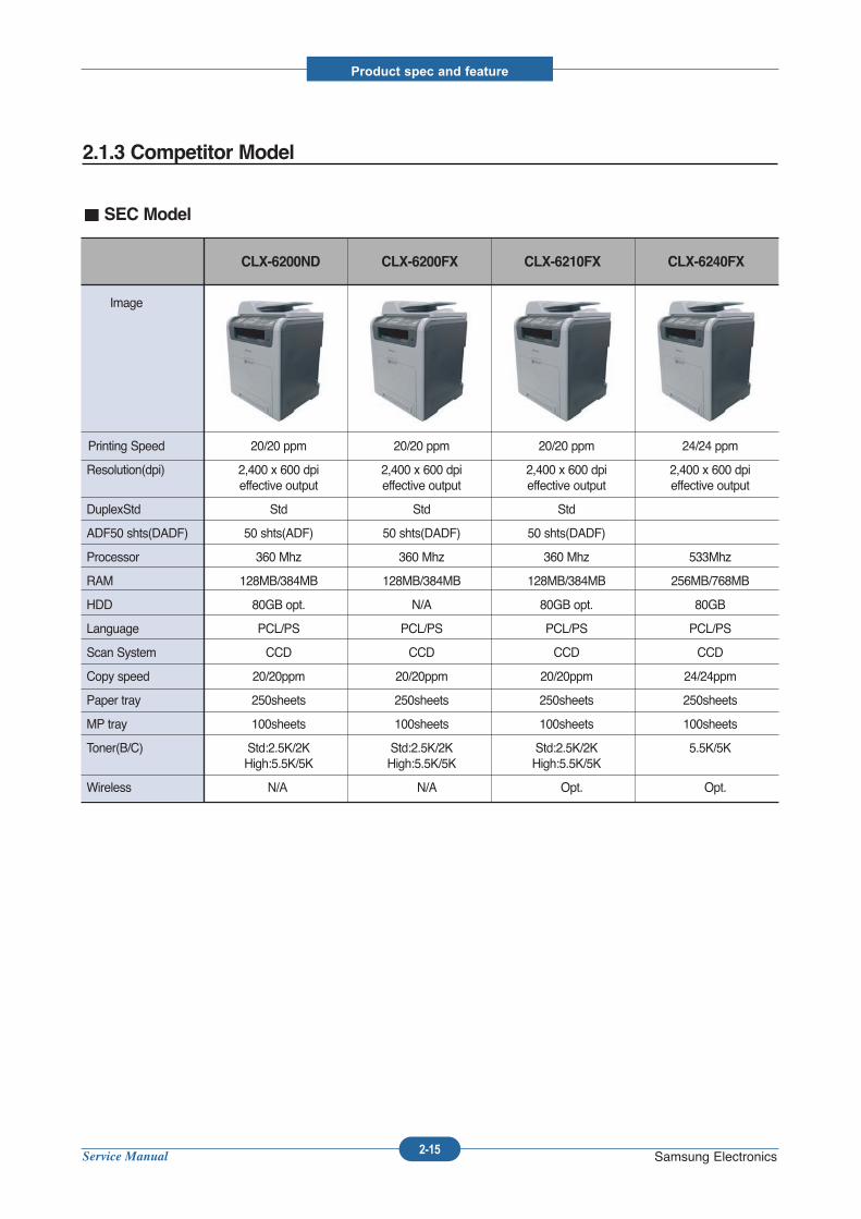
2.1.3 Competitor Model
Image
Printing Speed 20/20 ppm 20/20 ppm 20/20 ppm 24/24 ppm
Resolution(dpi) 2,400 x 600 dpi 2,400 x 600 dpi 2,400 x 600 dpi 2,400 x 600 dpieffective output effective output effective output effective output
DuplexStd Std Std Std
ADF50 shts(DADF) 50 shts(ADF) 50 shts(DADF) 50 shts(DADF)
Processor 360 Mhz 360 Mhz 360 Mhz 533Mhz
RAM 128MB/384MB 128MB/384MB 128MB/384MB 256MB/768MB
HDD 80GB opt. N/A 80GB opt. 80GB
Language PCL/PS PCL/PS PCL/PS PCL/PS
Scan System CCD CCD CCD CCD
Copy speed 20/20ppm 20/20ppm 20/20ppm 24/24ppm
Paper tray 250sheets 250sheets 250sheets 250sheets
MP tray 100sheets 100sheets 100sheets 100sheets
Toner(B/C) Std:2.5K/2K Std:2.5K/2K Std:2.5K/2K 5.5K/5KHigh:5.5K/5K High:5.5K/5K High:5.5K/5K
Wireless N/A N/A Opt. Opt.
CLX-6200ND CLX-6200FX CLX-6210FX CLX-6240FX
SEC Model
Service Manual
Product spec and feature
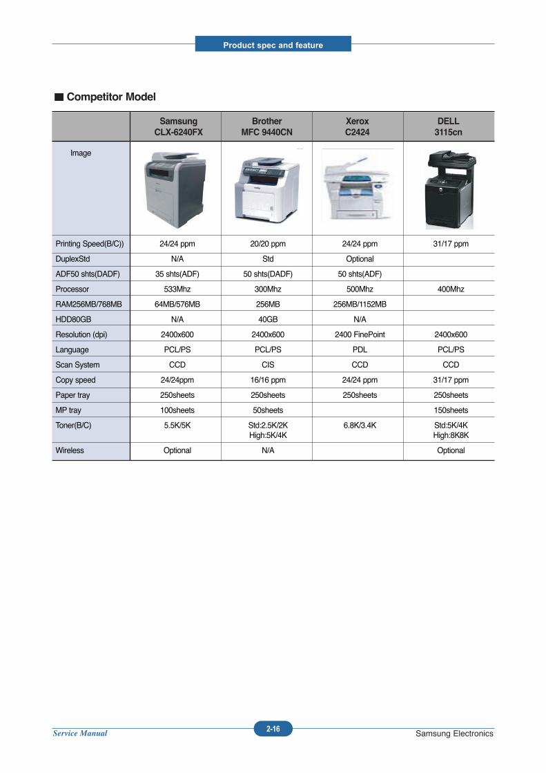
2-16 Samsung Electronics
Image
Printing Speed(B/C)) 24/24 ppm 20/20 ppm 24/24 ppm 31/17 ppm
DuplexStd N/A Std Optional
ADF50 shts(DADF) 35 shts(ADF) 50 shts(DADF) 50 shts(ADF)
Processor 533Mhz 300Mhz 500Mhz 400Mhz
RAM256MB/768MB 64MB/576MB 256MB 256MB/1152MB
HDD80GB N/A 40GB N/A
Resolution (dpi) 2400x600 2400x600 2400 FinePoint 2400x600
Language PCL/PS PCL/PS PDL PCL/PS
Scan System CCD CIS CCD CCD
Copy speed 24/24ppm 16/16 ppm 24/24 ppm 31/17 ppm
Paper tray 250sheets 250sheets 250sheets 250sheets
MP tray 100sheets 50sheets 150sheets
Toner(B/C) 5.5K/5K Std:2.5K/2K 6.8K/3.4K Std:5K/4KHigh:5K/4K High:8K8K
Wireless Optional N/A Optional
Samsung Brother Xerox DELL
CLX-6240FX MFC 9440CN C2424 3115cn
Competitor Model
Service Manual
Product spec and feature
2-17 Samsung Electronics
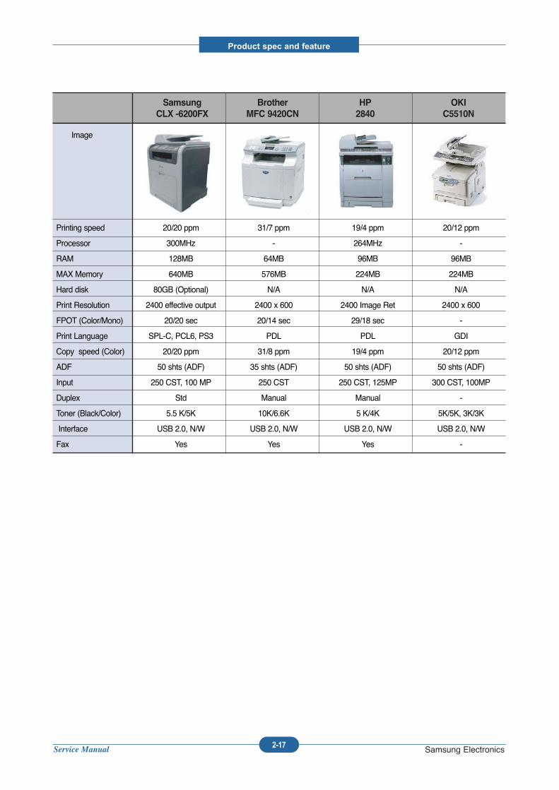
Image
Printing speed 20/20 ppm 31/7 ppm 19/4 ppm 20/12 ppm
Processor 300MHz - 264MHz -
RAM 128MB 64MB 96MB 96MB
MAX Memory 640MB 576MB 224MB 224MB
Hard disk 80GB (Optional) N/A N/A N/A
Print Resolution 2400 effective output 2400 x 600 2400 Image Ret 2400 x 600
FPOT (Color/Mono) 20/20 sec 20/14 sec 29/18 sec -
Print Language SPL-C, PCL6, PS3 PDL PDL GDI
Copy speed (Color) 20/20 ppm 31/8 ppm 19/4 ppm 20/12 ppm
ADF 50 shts (ADF) 35 shts (ADF) 50 shts (ADF) 50 shts (ADF)
Input 250 CST, 100 MP 250 CST 250 CST, 125MP 300 CST, 100MP
Duplex Std Manual Manual -
Toner (Black/Color) 5.5 K/5K 10K/6.6K 5 K/4K 5K/5K, 3K/3K
Interface USB 2.0, N/W USB 2.0, N/W USB 2.0, N/W USB 2.0, N/W
Fax Yes Yes Yes -
Samsung Brother HP OKI
CLX -6200FX MFC 9420CN 2840 C5510N
Service Manual
Product spec and feature
2-18 Samsung Electronics
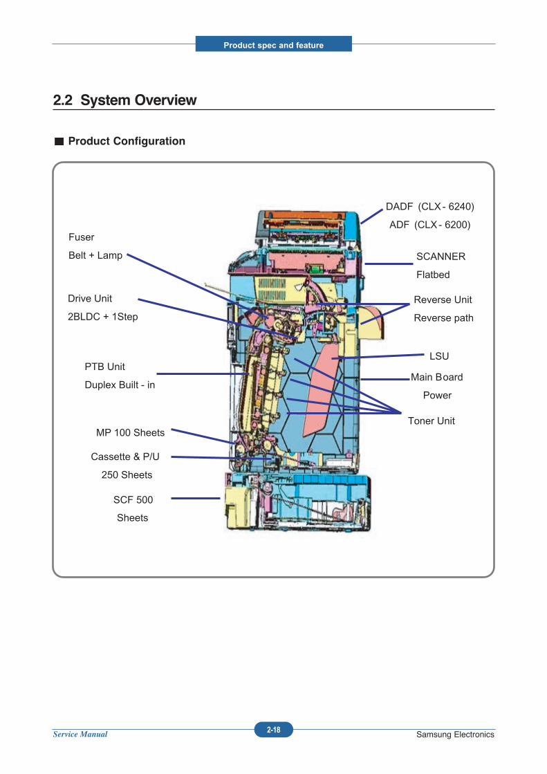
2.2 System Overview
Product Configuration
DADF (CLX - 6240)
ADF (CLX - 6200)
SCF 500
Sheets
SCANNER
Flatbed
Cassette & P/U
250 Sheets
MP 100 Sheets
Reverse Unit
Reverse path
Main Board
Power
Drive Unit
2BLDC + 1Step
Fuser
Belt + Lamp
Toner Unit
PTB Unit
Duplex Built - in
LSU
Service Manual
Product spec and feature
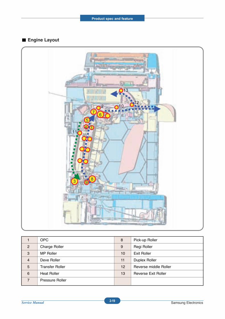
2-19 Samsung Electronics
1 OPC
2 Charge Roller
3 MP Roller
4 Deve Roller
5 Transfer Roller
6 Heat Roller
7 Pressure Roller
8 Pick-up Roller
9 Regi Roller
10 Exit Roller
11 Duplex Roller
12 Reverse middle Roller
13 Reverse Exit Roller
Engine Layout
93
1411
5
72
6
10
8
12
13
93
1411
5
72
6
10
8
12
13
Service Manual
Product spec and feature
2-20 Samsung Electronics
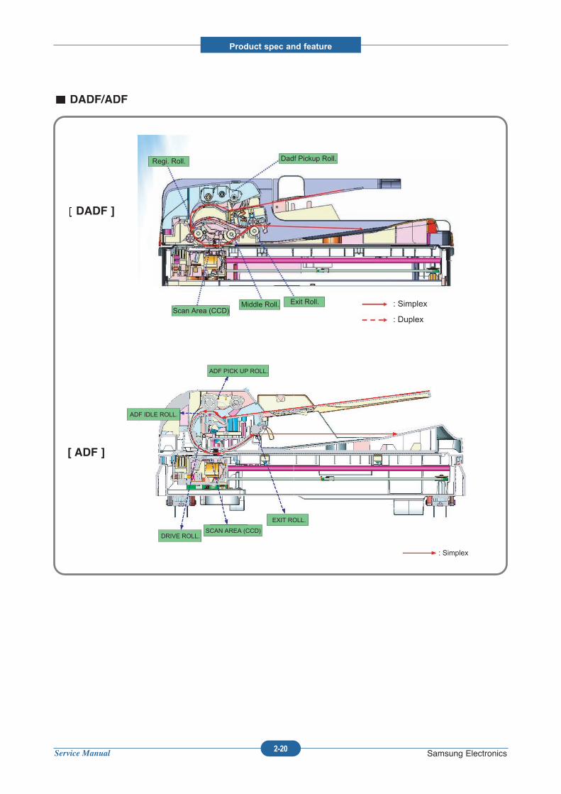
DADF/ADF
Regi. Roll.
Middle Roll.
ADF PICK UP ROLL.
ADF IDLE ROLL.
DRIVE ROLL.
EXIT ROLL.
SCAN AREA (CCD)
Exit Roll.
Dadf Pickup Roll.
Scan Area (CCD) : Simplex
: Duplex
: Simplex
DADF ]
[ ADF ]
Service Manual
Product spec and feature
2-21 Samsung Electronics
2.2.1 Main parts of system
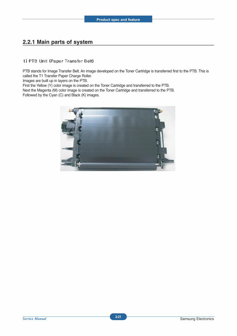
PTB stands for Image Transfer Belt. An image developed on the Toner Cartridge is transferred first to the PTB. This iscalled the T1 Transfer Paper Charge Roller.Images are built up in layers on the PTB.First the Yellow (Y) color image is created on the Toner Cartridge and transferred to the PTB.Next the Magenta (M) color image is created on the Toner Cartridge and transferred to the PTB.Followed by the Cyan (C) and Black (K) images.
Service Manual
Product spec and feature
2-22 Samsung Electronics
2) Transfer Roller
Once the complete, full color, image, has been built up on the PTB the Transfer Roller is used totransfer the image on to paper.
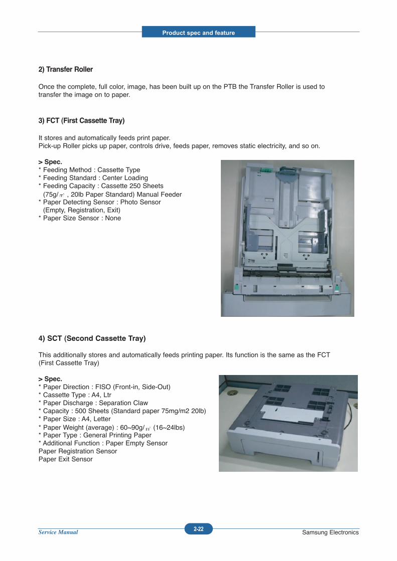
3) FCT (First Cassette Tray)
It stores and automatically feeds print paper.Pick-up Roller picks up paper, controls drive, feeds paper, removes static electricity, and so on.
> Spec.
* Feeding Method : Cassette Type* Feeding Standard : Center Loading* Feeding Capacity : Cassette 250 Sheets(75g/ , 20lb Paper Standard) Manual Feeder
* Paper Detecting Sensor : Photo Sensor (Empty, Registration, Exit)
* Paper Size Sensor : None
4) SCT (Second Cassette Tray)
This additionally stores and automatically feeds printing paper. Its function is the same as the FCT(First Cassette Tray)
> Spec.
* Paper Direction : FISO (Front-in, Side-Out)* Cassette Type : A4, Ltr* Paper Discharge : Separation Claw* Capacity : 500 Sheets (Standard paper 75mg/m2 20lb)* Paper Size : A4, Letter* Paper Weight (average) : 60~90g/ (16~24lbs)* Paper Type : General Printing Paper* Additional Function : Paper Empty SensorPaper Registration SensorPaper Exit Sensor
Service Manual
Product spec and feature
2-23 Samsung Electronics
5) MPT (Multi Purpose Tray)
The Multi-Purpose Tray not only feeds general printing paper but is also used for many other kindsof paper such as those paper sizes not supported by the cassette, envelopes, etc.
> Spec.
* Capacity : Cut Sheet : 100 Sheets (Standard paper 75mg/m2 bond)* OHP : 300 Sheets* Envelope & Label & Card Stock : 10 Sheets* Paper Arrangement : Center Loading* Power : Main Motor (Stepper Motor)* Driving Management : Solenoid* Paper Discharge : Friction Pad Method* Paper Size : Legal, Folio, A4, Letter, Executive, JIS B5, A5, A6* Paper Weight (Average) : 75~163g/m2 bond(20 to 43lb)* Paper Type : General, Label, Post Card, Transparency, Envelope, Card Stock (Tracing Paper is notserved)* Additional Function : Paper Empty Sensor
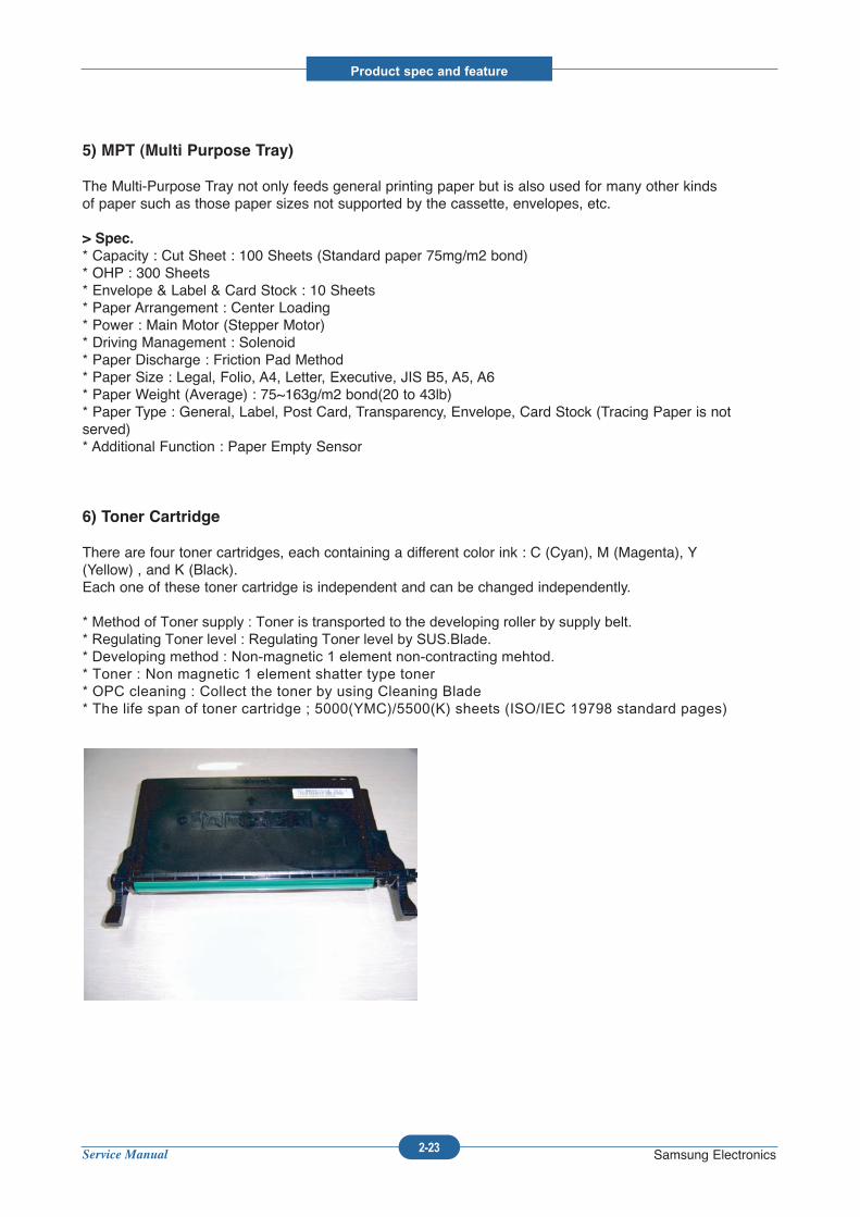
6) Toner Cartridge
There are four toner cartridges, each containing a different color ink : C (Cyan), M (Magenta), Y(Yellow) , and K (Black).Each one of these toner cartridge is independent and can be changed independently.
* Method of Toner supply : Toner is transported to the developing roller by supply belt.* Regulating Toner level : Regulating Toner level by SUS.Blade.* Developing method : Non-magnetic 1 element non-contracting mehtod.* Toner : Non magnetic 1 element shatter type toner* OPC cleaning : Collect the toner by using Cleaning Blade * The life span of toner cartridge ; 5000(YMC)/5500(K) sheets (ISO/IEC 19798 standard pages)
Service Manual
Product spec and feature
2-24 Samsung Electronics
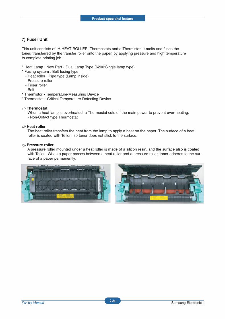
7) Fuser Unit
This unit consists of IH-HEAT ROLLER, Thermostats and a Thermistor. It melts and fuses thetoner, transferred by the transfer roller onto the paper, by applying pressure and high temperatureto complete printing job.
* Heat Lamp : New Part - Dual Lamp Type (6200:Single lamp type)* Fusing system : Belt fusing type- Heat roller : Pipe type (Lamp inside)- Pressure roller- Fuser roller- Belt
* Thermistor - Temperature-Measuring Device* Thermostat - Critical Temperature-Detecting Device
ThermostatWhen a heat lamp is overheated, a Thermostat cuts off the main power to prevent over-heating.- Non-Cotact type Thermostat
Heat rollerThe heat roller transfers the heat from the lamp to apply a heat on the paper. The surface of a heatroller is coated with Teflon, so toner does not stick to the surface.
Pressure rollerA pressure roller mounted under a heat roller is made of a silicon resin, and the surface also is coatedwith Teflon. When a paper passes between a heat roller and a pressure roller, toner adheres to the sur-face of a paper permanently.
Service Manual
Product spec and feature
2-25 Samsung Electronics
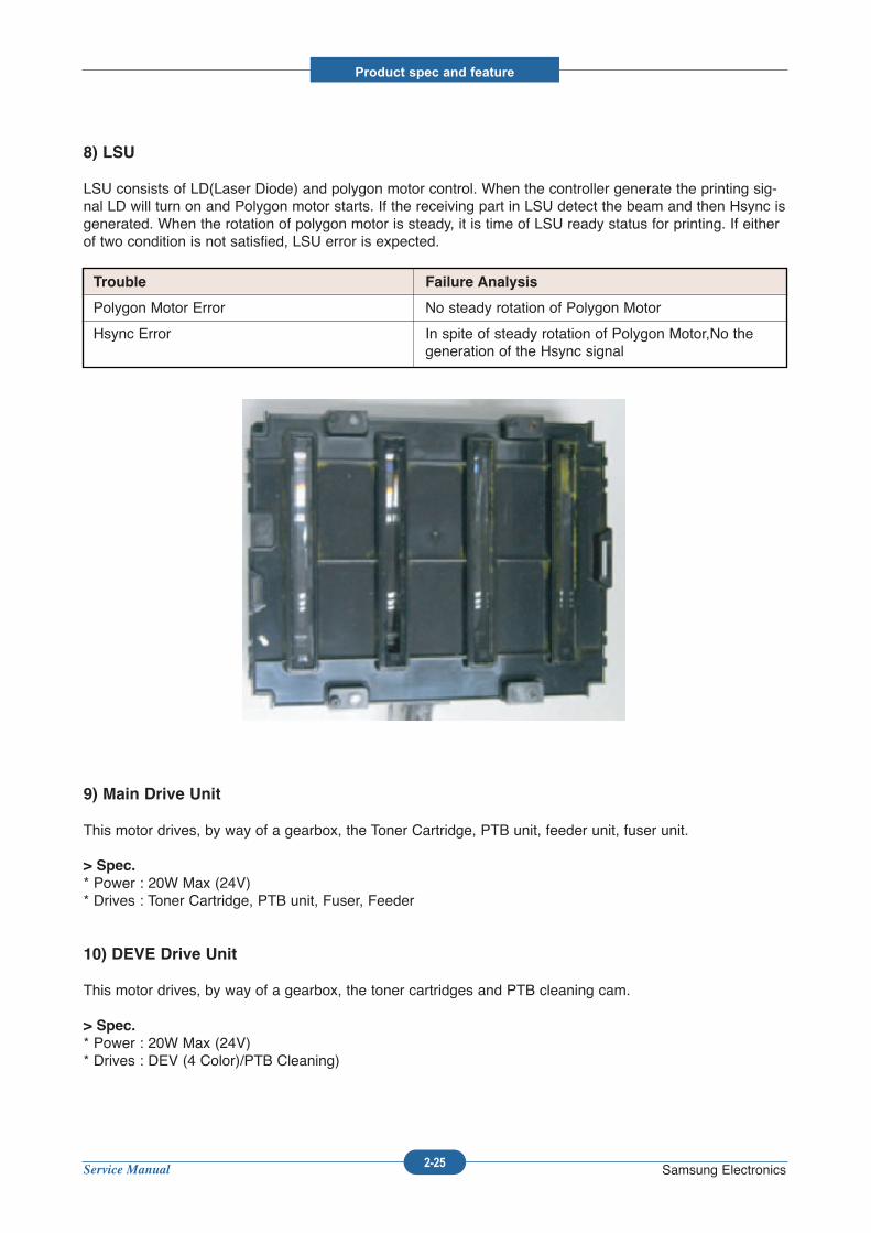
8) LSU
LSU consists of LD(Laser Diode) and polygon motor control. When the controller generate the printing sig-nal LD will turn on and Polygon motor starts. If the receiving part in LSU detect the beam and then Hsync isgenerated. When the rotation of polygon motor is steady, it is time of LSU ready status for printing. If eitherof two condition is not satisfied, LSU error is expected.
9) Main Drive Unit
This motor drives, by way of a gearbox, the Toner Cartridge, PTB unit, feeder unit, fuser unit.
> Spec.
* Power : 20W Max (24V)* Drives : Toner Cartridge, PTB unit, Fuser, Feeder
10) DEVE Drive Unit
This motor drives, by way of a gearbox, the toner cartridges and PTB cleaning cam.
> Spec.
* Power : 20W Max (24V)* Drives : DEV (4 Color)/PTB Cleaning)
Trouble Failure Analysis
Polygon Motor Error No steady rotation of Polygon Motor
Hsync Error In spite of steady rotation of Polygon Motor,No thegeneration of the Hsync signal
Service Manual
Product spec and feature
2-26 Samsung Electronics
11) SMPS (Switching Mode Power Supply)
This power supply uses the AC supply voltage to generate the DC voltages used by the system.The SMPS has 5 output channels (+3.3V, +5V, +24V).
12) HVPS (High Voltage Power Supply)
The HVPS creates the high voltages (Transfer, Charge, Attr, Supply DC, Supply AC) used for theelectro photographic process. The high voltage is created from the 24V line from the SMPS. HighVoltage output is supplied to the toner cartridge, PTB unit.
13) Main Controller PBA
The Main controller PBA is very important as it is the heart of printer. It has several major functionblocks.
* CPU : This manages the printing order from the host, creates bitmap data for theengine to print and controls various devices that are needed to operate the printer.*Engine Control Block: This manages images and controls various kinds of I/O* Memory Block : The operating system uses this to store video data and printing orders given by host.* ROM Block : The printer OS and PDL Interpreter are stored here.* In addition there are USB 2.0 Block, IEEE 1284 Block, Option Block, OPE Panel, etc.
14) Drive PBA
Each toner cartridge requires the HV Supply only when that colour image is being processed. Thisunit takes its HV source from the HVPS and using 4 solenoids selects which cartridge is to receivethe Supply voltage. This section also contains the DEVE motor, DEVE clutch, and DEVE solenoiddrives. These are activated in sequence as required by the printing process.
15) DEVE CRUM PBA
This detects new or used toner cartridges and also checks that cartridges are approved parts. If atoner cartridge is not suitable for the machine an error message is displayed.
Service Manual
Product spec and feature
2-27 Samsung Electronics
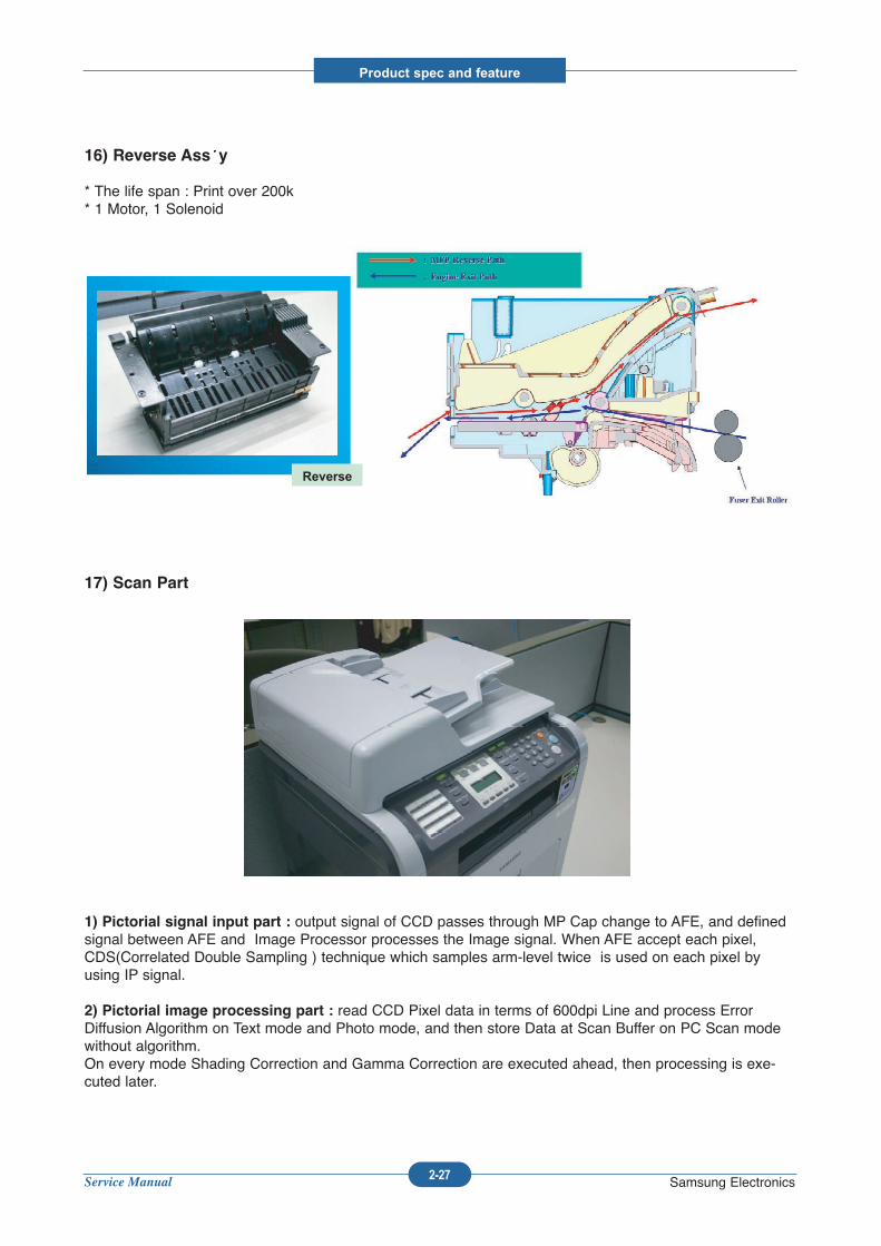
16) Reverse Ass y
* The life span : Print over 200k* 1 Motor, 1 Solenoid
17) Scan Part
1) Pictorial signal input part : output signal of CCD passes through MP Cap change to AFE, and definedsignal between AFE and Image Processor processes the Image signal. When AFE accept each pixel,CDS(Correlated Double Sampling ) technique which samples arm-level twice is used on each pixel byusing IP signal.
2) Pictorial image processing part : read CCD Pixel data in terms of 600dpi Line and process ErrorDiffusion Algorithm on Text mode and Photo mode, and then store Data at Scan Buffer on PC Scan modewithout algorithm.On every mode Shading Correction and Gamma Correction are executed ahead, then processing is exe-cuted later.
Reverse
Service Manual
Product spec and feature
2-28 Samsung Electronics
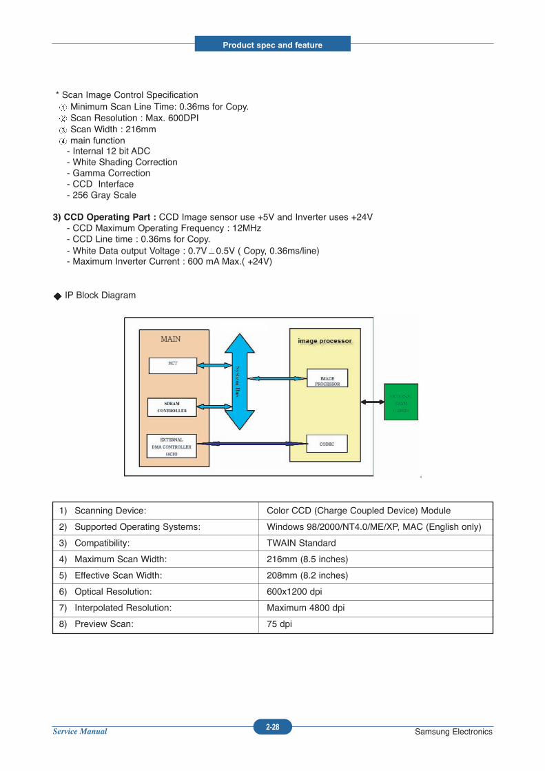
* Scan Image Control SpecificationMinimum Scan Line Time: 0.36ms for Copy.Scan Resolution : Max. 600DPIScan Width : 216mmmain function- Internal 12 bit ADC- White Shading Correction- Gamma Correction - CCD Interface- 256 Gray Scale
3) CCD Operating Part : CCD Image sensor use +5V and Inverter uses +24V- CCD Maximum Operating Frequency : 12MHz- CCD Line time : 0.36ms for Copy.- White Data output Voltage : 0.7V 0.5V ( Copy, 0.36ms/line)- Maximum Inverter Current : 600 mA Max.( +24V)
IP Block Diagram
1) Scanning Device: Color CCD (Charge Coupled Device) Module
2) Supported Operating Systems: Windows 98/2000/NT4.0/ME/XP, MAC (English only)
3) Compatibility: TWAIN Standard
4) Maximum Scan Width: 216mm (8.5 inches)
5) Effective Scan Width: 208mm (8.2 inches)
6) Optical Resolution: 600x1200 dpi
7) Interpolated Resolution: Maximum 4800 dpi
8) Preview Scan: 75 dpi
Service Manual
Product spec and feature
2-29 Samsung Electronics
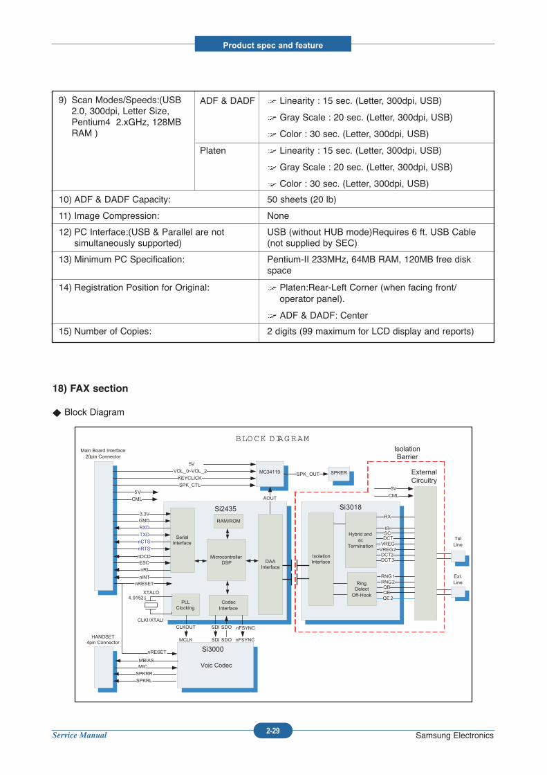
18) FAX section
Block Diagram
IsolationInterface
Hybrid anddc
Termination
Ring DetectOff-Hook
RX
IBSCDCTVREGVREG2DCT2DCT3
RNG1RNG2QBQEQE2
Si3018Si2435
DAAInterface
MicrocontrollerDSP
PLLClocking
RAM/ROM
ExternalCircuitry
Isolation Barrier
CLKOUT
RXD
CodecInterface
4.9152§XTALO
CLKI /XTALI
SDI SDO nFSYNC
TXD
nCTS
nRTS
nDCDESC
nRI
nINT
Voic Codec
Si3000
MCLK nFSYNCSDI SDO
nRESET
nRESET
MBIASMIC
HANDSET4pin Connector
Main Board Interface20pin Connector
GND3.3V
Tel Line
Ext. Line
5V
CML
BLOCK DIAGRAM
MC34119
AOUT
SPK_CTL
KEYCLICK
VOL_0~VOL_2SPK_OUT SPKER
SerialInterface
5VCML
5V
SPKRR
SPKRL
ADF & DADF Linearity : 15 sec. (Letter, 300dpi, USB)
Gray Scale : 20 sec. (Letter, 300dpi, USB)
Color : 30 sec. (Letter, 300dpi, USB)
Platen Linearity : 15 sec. (Letter, 300dpi, USB)
Gray Scale : 20 sec. (Letter, 300dpi, USB)
Color : 30 sec. (Letter, 300dpi, USB)
10) ADF & DADF Capacity: 50 sheets (20 lb)
11) Image Compression: None
12) PC Interface:(USB & Parallel are not USB (without HUB mode)Requires 6 ft. USB Cablesimultaneously supported) (not supplied by SEC)
13) Minimum PC Specification: Pentium-II 233MHz, 64MB RAM, 120MB free diskspace
14) Registration Position for Original: Platen:Rear-Left Corner (when facing front/operator panel).
ADF & DADF: Center
15) Number of Copies: 2 digits (99 maximum for LCD display and reports)
9) Scan Modes/Speeds:(USB2.0, 300dpi, Letter Size,Pentium4 2.xGHz, 128MBRAM )
Service Manual
Product spec and feature
2-30 Samsung Electronics
Implemented by based on the silicon DAA (Data Access Arrangement) Solution, and is roughly composedof two Chip Solution
SI2435(SSD) A Modem Chip which embeds SSD (System Side Device) for interfacing betweenLSD and Voice Codec(SI3000)
SI3018 (LSD) A LIU (Line Interface Unit) Chip which is controlled by SSD and satisfies eachPSTN Requirements by modulating internal Configuration with connecting Tel Line.
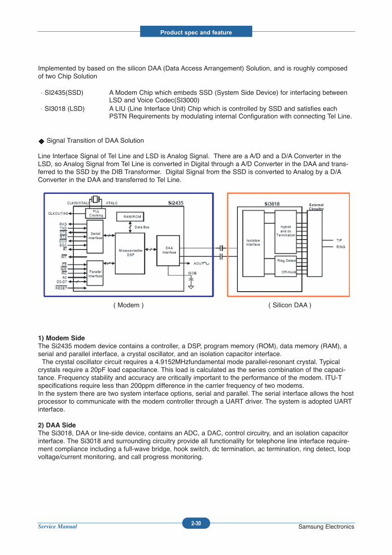
Signal Transition of DAA Solution
Line Interface Signal of Tel Line and LSD is Analog Signal. There are a A/D and a D/A Converter in theLSD, so Analog Signal from Tel Line is converted in Digital through a A/D Converter in the DAA and trans-ferred to the SSD by the DIB Transformer. Digital Signal from the SSD is converted to Analog by a D/AConverter in the DAA and transferred to Tel Line.
1) Modem Side
The Si2435 modem device contains a controller, a DSP, program memory (ROM), data memory (RAM), aserial and parallel interface, a crystal oscillator, and an isolation capacitor interface.The crystal oscillator circuit requires a 4.9152MHzfundamental mode parallel-resonant crystal. Typical
crystals require a 20pF load capacitance. This load is calculated as the series combination of the capaci-tance. Frequency stability and accuracy are critically important to the performance of the modem. ITU-Tspecifications require less than 200ppm difference in the carrier frequency of two modems.In the system there are two system interface options, serial and parallel. The serial interface allows the hostprocessor to communicate with the modem controller through a UART driver. The system is adopted UARTinterface.
2) DAA Side
The Si3018, DAA or line-side device, contains an ADC, a DAC, control circuitry, and an isolation capacitorinterface. The Si3018 and surrounding circuitry provide all functionality for telephone line interface require-ment compliance including a full-wave bridge, hook switch, dc termination, ac termination, ring detect, loopvoltage/current monitoring, and call progress monitoring.
( Modem ) ( Silicon DAA )
Service Manual
Product spec and feature
2-31 Samsung Electronics
3) Speaker Driver
The AOUT signal from the Si2435 modem chip is only available in the serial DTE interface mode. AOUT isa 50% duty cycle, 32kHz, square wave pulse-width modulated (PWM) by voice band audio, such as calprogress tones.
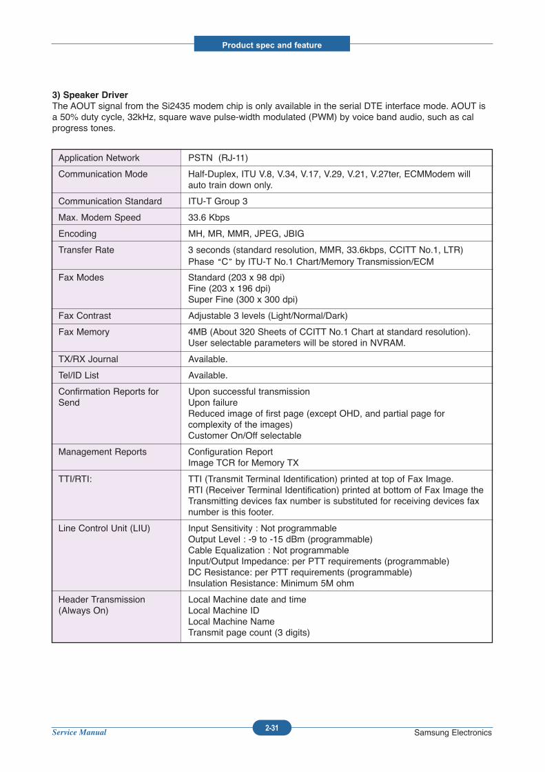
Application Network PSTN (RJ-11)
Communication Mode Half-Duplex, ITU V.8, V.34, V.17, V.29, V.21, V.27ter, ECMModem willauto train down only.
Communication Standard ITU-T Group 3
Max. Modem Speed 33.6 Kbps
Encoding MH, MR, MMR, JPEG, JBIG
Transfer Rate 3 seconds (standard resolution, MMR, 33.6kbps, CCITT No.1, LTR)Phase C by ITU-T No.1 Chart/Memory Transmission/ECM
Fax Modes Standard (203 x 98 dpi)Fine (203 x 196 dpi)Super Fine (300 x 300 dpi)
Fax Contrast Adjustable 3 levels (Light/Normal/Dark)
Fax Memory 4MB (About 320 Sheets of CCITT No.1 Chart at standard resolution).User selectable parameters will be stored in NVRAM.
TX/RX Journal Available.
Tel/ID List Available.
Confirmation Reports for Upon successful transmissionSend Upon failure
Reduced image of first page (except OHD, and partial page for complexity of the images)Customer On/Off selectable
Management Reports Configuration ReportImage TCR for Memory TX
TTI/RTI: TTI (Transmit Terminal Identification) printed at top of Fax Image.RTI (Receiver Terminal Identification) printed at bottom of Fax Image theTransmitting devices fax number is substituted for receiving devices faxnumber is this footer.
Line Control Unit (LIU) Input Sensitivity : Not programmableOutput Level : -9 to -15 dBm (programmable)Cable Equalization : Not programmableInput/Output Impedance: per PTT requirements (programmable)DC Resistance: per PTT requirements (programmable)Insulation Resistance: Minimum 5M ohm
Header Transmission Local Machine date and time(Always On) Local Machine ID
Local Machine NameTransmit page count (3 digits)
Service Manual
Product spec and feature
2-32 Samsung Electronics
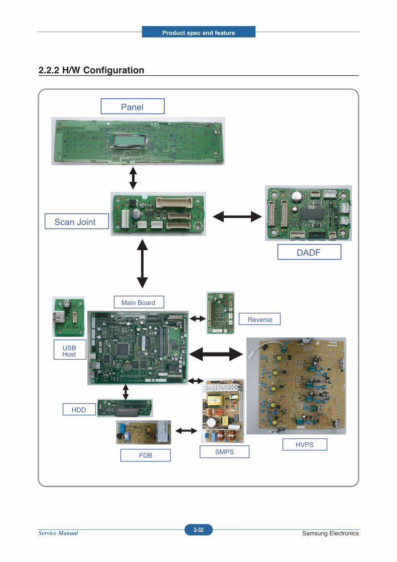
2.2.2 H/W Configuration
Panel
Scan Joint
DADF
SMPS
Main Board
HVPS FDB
HDD
Reverse
USB Host
Service Manual
Product spec and feature
2-33 Samsung Electronics
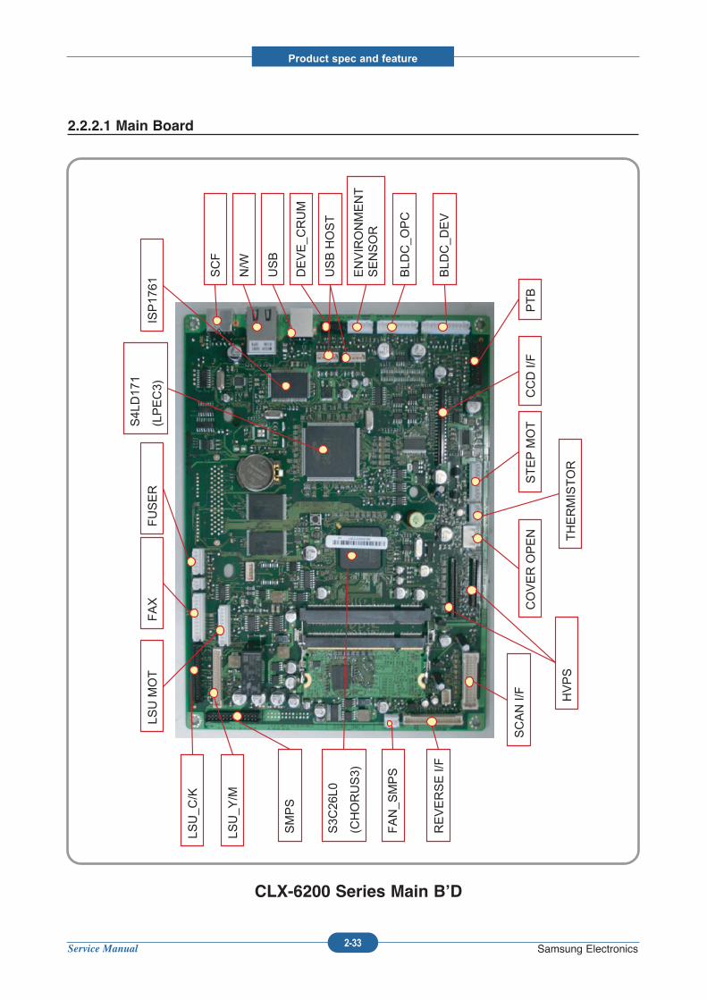
2.2.2.1 Main Board
LSU_C
/K
LSU MOT
FAX
LSU_Y
/M
S4L
D17
1
(LPEC3)
SMPS
FAN_S
MPS
REVERSE I/F
SCAN I/F
THERMISTOR
STEP MOT
N/W
DEVE_C
RUM
ENVIRONMENT
SENSOR
BLD
C_O
PC
BLD
C_D
EV
PTB
ISP17
61FUSER
CCD I/F
COVER OPEN
HVPS
USB
SCF
S3C
26L0
(CHORUS3)
USB HOST
CLX-6200 Series Main B’D
Service Manual
Product spec and feature
2-34 Samsung Electronics
BLD
C_D
EV
BLD
C_O
PC
ENVIRONMENT
SENSOR
PTB
STEP MOT
SCAN
SMPS
REVERSE
LSU_M
OT
LSU Y/M
RM70
65C
S4L
D17
1(LPEC3)
HVPS
USB HOST
USB HOST
N/W
S3C
A6S
0(Xm)
S4L
D14
6(CIP5)
HDD
LSU C/K
FUSER
WNIC
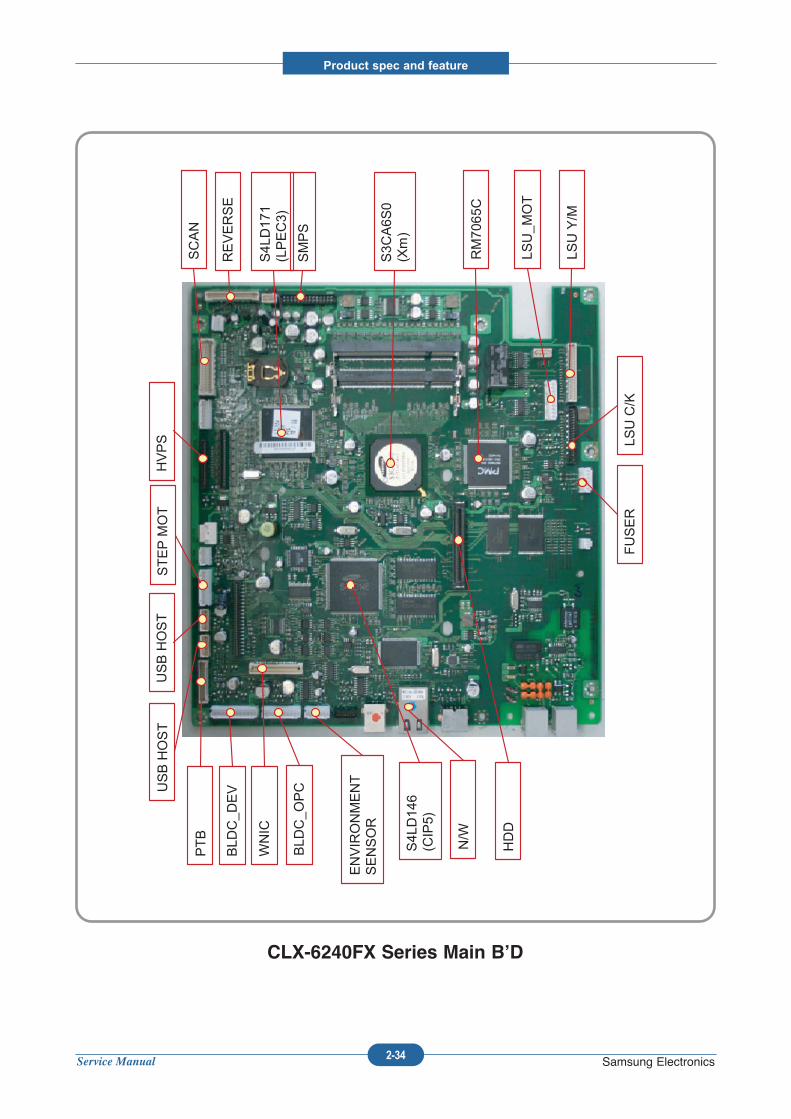
CLX-6240FX Series Main B’D
Service Manual
Product spec and feature
2-35 Samsung Electronics
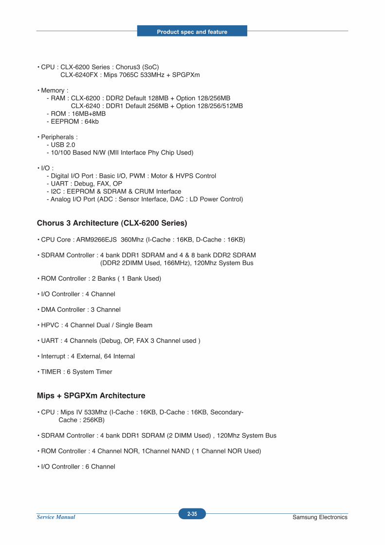
• CPU : CLX-6200 Series : Chorus3 (SoC)CLX-6240FX : Mips 7065C 533MHz + SPGPXm
• Memory : - RAM : CLX-6200 : DDR2 Default 128MB + Option 128/256MB
CLX-6240 : DDR1 Default 256MB + Option 128/256/512MB- ROM : 16MB+8MB- EEPROM : 64kb
• Peripherals : - USB 2.0 - 10/100 Based N/W (MII Interface Phy Chip Used)
• I/O : - Digital I/O Port : Basic I/O, PWM : Motor & HVPS Control- UART : Debug, FAX, OP- I2C : EEPROM & SDRAM & CRUM Interface - Analog I/O Port (ADC : Sensor Interface, DAC : LD Power Control)
Chorus 3 Architecture (CLX-6200 Series)
• CPU Core : ARM9266EJS 360Mhz (I-Cache : 16KB, D-Cache : 16KB)
• SDRAM Controller : 4 bank DDR1 SDRAM and 4 & 8 bank DDR2 SDRAM(DDR2 2DIMM Used, 166MHz), 120Mhz System Bus
• ROM Controller : 2 Banks ( 1 Bank Used)
• I/O Controller : 4 Channel
• DMA Controller : 3 Channel
• HPVC : 4 Channel Dual / Single Beam
• UART : 4 Channels (Debug, OP, FAX 3 Channel used )
• Interrupt : 4 External, 64 Internal
• TIMER : 6 System Timer
Mips + SPGPXm Architecture
• CPU : Mips IV 533Mhz (I-Cache : 16KB, D-Cache : 16KB, Secondary-Cache : 256KB)
• SDRAM Controller : 4 bank DDR1 SDRAM (2 DIMM Used) , 120Mhz System Bus
• ROM Controller : 4 Channel NOR, 1Channel NAND ( 1 Channel NOR Used)
• I/O Controller : 6 Channel
Service Manual
Product spec and feature
2-36 Samsung Electronics
• DMA Controller : 4 Channel
• HPVC : 4 Channel Dual / Single Beam
• UART : 5 Channels (Debug, OP, FAX 3 Channel used)
• Interrupt : 10 External
• TIMER : 6 System Timer
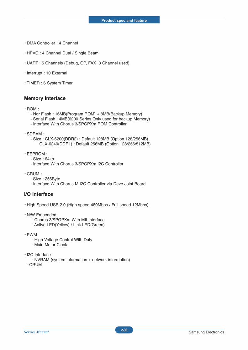
Memory Interface
• ROM : - Nor Flash : 16MB(Program ROM) + 8MB(Backup Memory)- Serial Flash : 4MB(6200 Series Only used for backup Memory) - Interface With Chorus 3/SPGPXm ROM Controller
• SDRAM : - Size : CLX-6200(DDR2) : Default 128MB (Option 128/256MB)
CLX-6240(DDR1) : Default 256MB (Option 128/256/512MB)
• EEPROM : - Size : 64kb- Interface With Chorus 3/SPGPXm I2C Controller
• CRUM : - Size : 256Byte- Interface With Chorus M I2C Controller via Deve Joint Board
I/O Interface
• High Speed USB 2.0 (High speed 480Mbps / Full speed 12Mbps)
• N/W Embedded- Chorus 3/SPGPXm With MII Interface- Active LED(Yellow) / Link LED(Green)
• PWM - High Voltage Control With Duty- Main Motor Clock
• I2C Interface - NVRAM (system information + network information)
- CRUM
Service Manual
Product spec and feature
2-37 Samsung Electronics
2.2.2.2 Power Flow
• SMPS- Type V (standard type)- +24V : For use Mechanical Part (Motor & Actuator (Solenoid, Clutch)), CCDM- +5V : Logic, Analog, Sensor
• Main B’D- Supply From SMPS +5V- Power Supply with Regulator (3.3V & 1.2V & 1.0V : Switching Regulator)- 3.3V : I/O Operating (Digital & Analog)- 1.0V : Chorus 3 Core Voltage- 1.2V : SPGPXm Core Voltage
• HVPS- High Voltage Source for EP Condition- Supply From SMPS +24V- Controlled By PWM Pulse & I/O
Service Manual
Product spec and feature
2-38 Samsung Electronics
1 2 3
4
5
67
8
CHARGER
DEV SUPPLY
TRANSFER
ATTR
ERASER
FUSER BIAS
COVER OPEN SWITCH
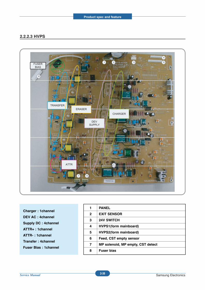
2.2.2.3 HVPS
Charger : 1channel
DEV AC : 4channel
Supply DC : 4channel
ATTR+ : 1channel
ATTR- : 1channel
Transfer : 4channel
Fuser Bias : 1channel
1 PANEL
2 EXIT SENSOR
3 24V SWITCH
4 HVPS1(form mainboard)
5 HVPS2(form mainboard)
6 Feed, CST empty sensor
7 MP solenoid, MP empty, CST detect
8 Fuser bias
Service Manual
Product spec and feature
2-39 Samsung Electronics
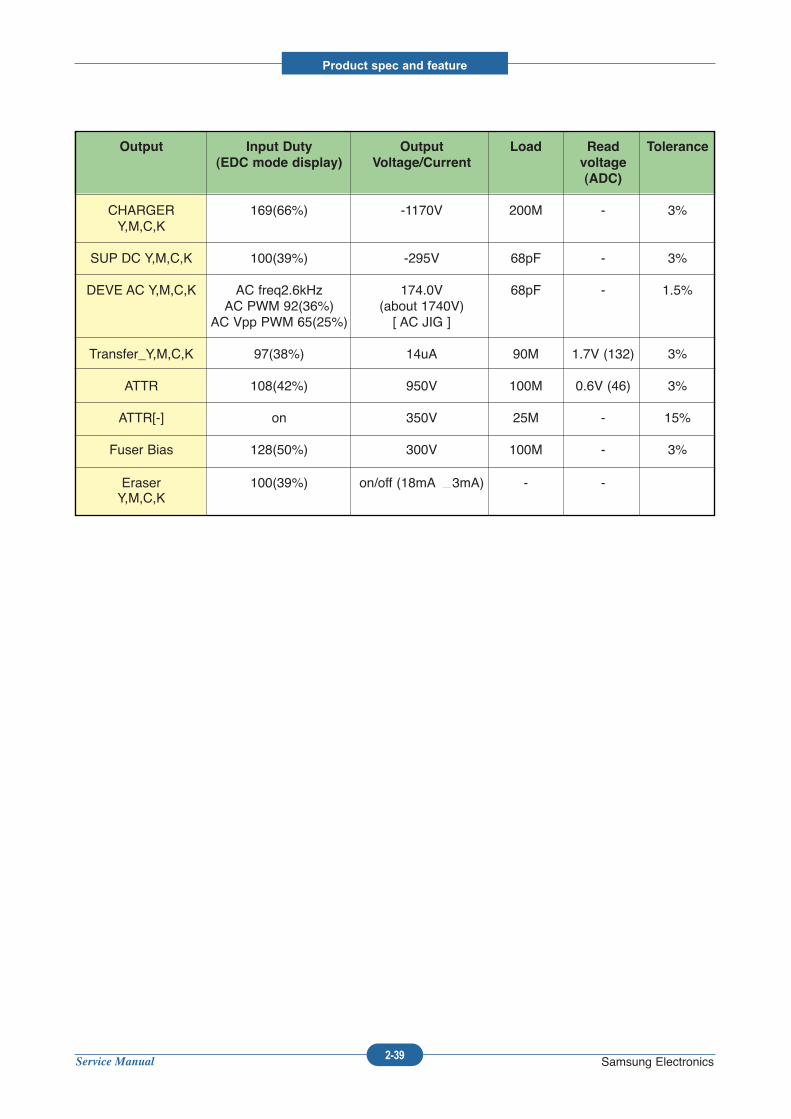
Output Input Duty Output Load Read Tolerance
(EDC mode display) Voltage/Current voltage
(ADC)
CHARGER 169(66%) -1170V 200M - 3%Y,M,C,K
SUP DC Y,M,C,K 100(39%) -295V 68pF - 3%
DEVE AC Y,M,C,K AC freq2.6kHz 174.0V 68pF - 1.5%AC PWM 92(36%) (about 1740V)
AC Vpp PWM 65(25%) [ AC JIG ]
Transfer_Y,M,C,K 97(38%) 14uA 90M 1.7V (132) 3%
ATTR 108(42%) 950V 100M 0.6V (46) 3%
ATTR[-] on 350V 25M - 15%
Fuser Bias 128(50%) 300V 100M - 3%
Eraser 100(39%) on/off (18mA 3mA) - -Y,M,C,K
Service Manual
Product spec and feature
2-40 Samsung Electronics
1
1
2
2
3
4
4
3
FUSE
FUSE
PHOTO TRIAC
PHOTO TRIAC
TRIAC
TRIAC
VARISTOR
VARISTOR
CLP-660
CLP-610
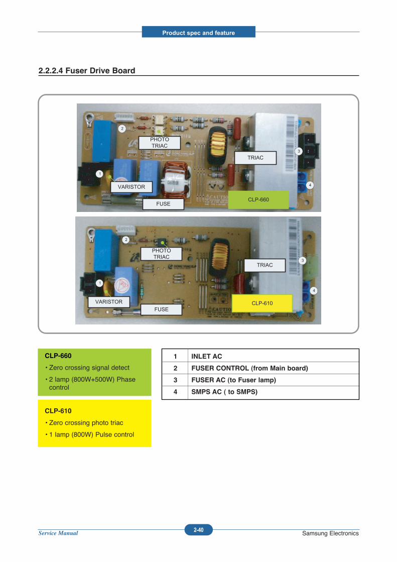
2.2.2.4 Fuser Drive Board
CLP-660
• Zero crossing signal detect
• 2 lamp (800W+500W) Phasecontrol
CLP-610
• Zero crossing photo triac
• 1 lamp (800W) Pulse control
1 INLET AC
2 FUSER CONTROL (from Main board)
3 FUSER AC (to Fuser lamp)
4 SMPS AC ( to SMPS)
Service Manual
Product spec and feature
2-41 Samsung Electronics
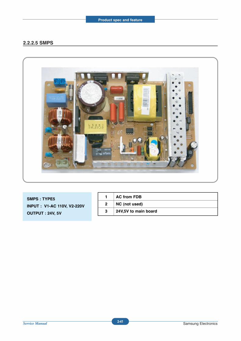
2.2.2.5 SMPS
SMPS : TYPE5
INPUT : V1-AC 110V, V2-220V
OUTPUT : 24V, 5V
1 AC from FDB
2 NC (not used)
3 24V,5V to main board
Service Manual
Product spec and feature
2-42 Samsung Electronics
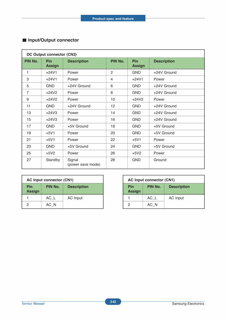
DC Output connector (CN3)
PIN No. Pin Description PIN No. Pin Description
Assign Assign
1 +24V1 Power 2 GND +24V Ground
3 +24V1 Power 4 +24V1 Power
5 GND +24V Ground 6 GND +24V Ground
7 +24V2 Power 8 GND +24V Ground
9 +24V2 Power 10 +24V2 Power
11 GND +24V Ground 12 GND +24V Ground
13 +24V3 Power 14 GND +24V Ground
15 +24V3 Power 16 GND +24V Ground
17 GND +5V Ground 18 GND +5V Ground
19 +5V1 Power 20 GND +5V Ground
21 +5V1 Power 22 +5V1 Power
23 GND +5V Ground 24 GND +5V Ground
25 +5V2 Power 26 +5V2 Power
27 Standby Signal 28 GND Ground(power save mode)
AC Input connector (CN1)
Pin PIN No. Description
Assign
1 AC_L AC Input
2 AC_N
AC Input connector (CN1)
Pin PIN No. Description
Assign
1 AC_L AC Input
2 AC_N
Input/Output connector
Service Manual
Product spec and feature
2-43 Samsung Electronics
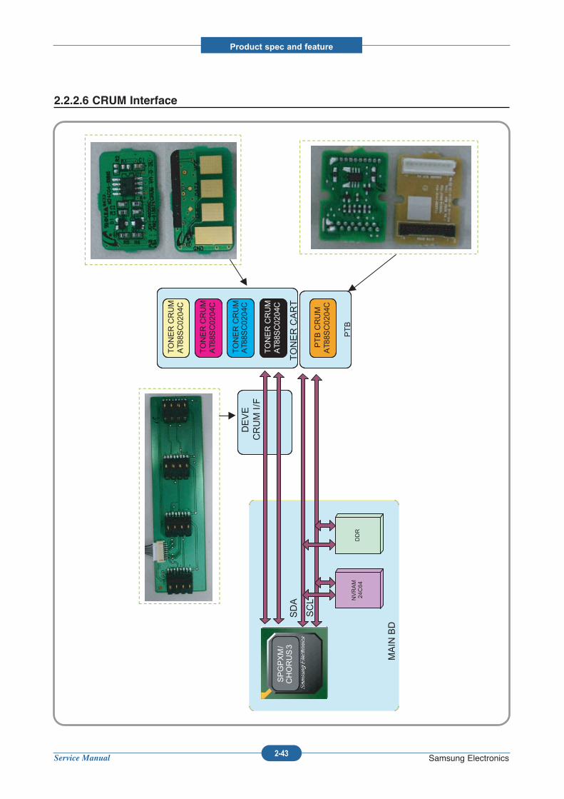
SDA
SCL N
VRAM
24C64
MAIN BD
DEVE
CRUM I/F
DDR
TONER CRUM
AT88S
C02
04C
TONER CRUM
AT88S
C02
04C
TONER CRUM
AT88S
C02
04C
TONER CRUM
AT88S
C02
04C
TONER CART
SPGPXM/
CHORUS3
PTB
PTB CRUM
AT88S
C02
04C
2.2.2.6 CRUM Interface
Service Manual
Disassembly and Reassembly
3-1 Samsung Electronics
3. Disassembly and Reassembly
3.1 General Precautions on Disassembly
When you disassemble and reassemble compo-nents, you must use extreme caution. The closeproximity of cables to moving parts makes properrouting a must. If components are removed, any cables disturbedby the procedure must be restored as close aspossible to their original positions. Before remov-ing any component from the machine, note thecable routing that will be affected.
Whenever servicing the machine, you
must perform as follows:
1. Check to verify that documents are not storedin memory.
2. Be sure to remove the print cartridge beforeyou disassemble parts.
3. Unplug the power cord.
4. Use a flat and clean surface.
5. Replace only with authorized components.
6. Do not force plastic-material components.
7. Make sure all components are in their properposition.
Releasing Plastic Latches
Many of the parts are held in place with plasticlatches. The latches break easily; release themcarefully. To remove such parts, press the hook end of thelatch away from the part to which it is latched.
Service Manual
Disassembly and Reassembly
3-2 Samsung Electronics
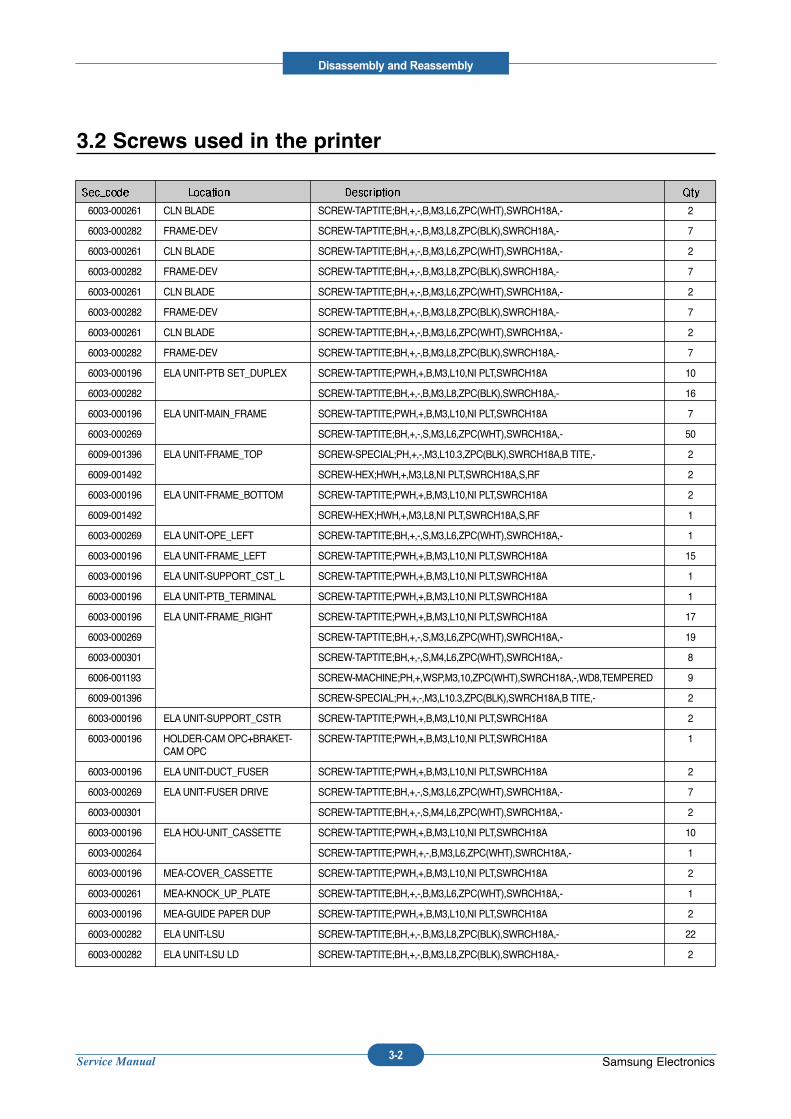
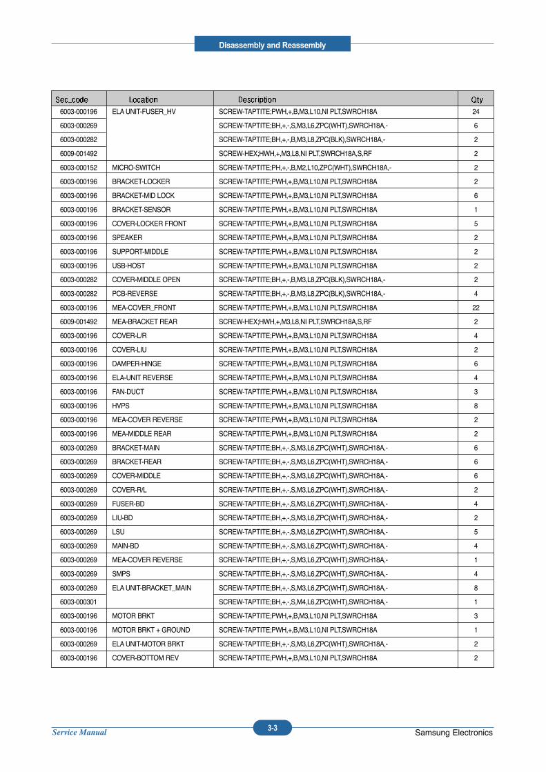
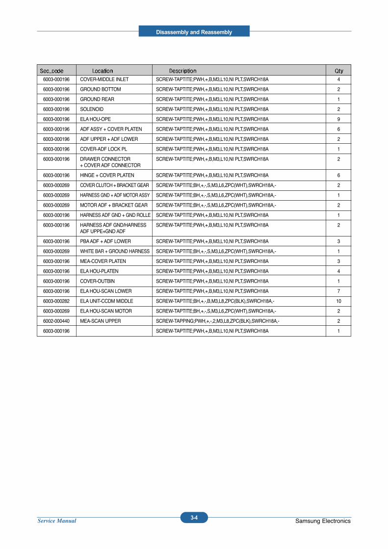
3.2 Screws used in the printer
6003-000261 CLN BLADE SCREW-TAPTITE;BH,+,-,B,M3,L6,ZPC(WHT),SWRCH18A,- 2
6003-000282 FRAME-DEV SCREW-TAPTITE;BH,+,-,B,M3,L8,ZPC(BLK),SWRCH18A,- 7
6003-000261 CLN BLADE SCREW-TAPTITE;BH,+,-,B,M3,L6,ZPC(WHT),SWRCH18A,- 2
6003-000282 FRAME-DEV SCREW-TAPTITE;BH,+,-,B,M3,L8,ZPC(BLK),SWRCH18A,- 7
6003-000261 CLN BLADE SCREW-TAPTITE;BH,+,-,B,M3,L6,ZPC(WHT),SWRCH18A,- 2
6003-000282 FRAME-DEV SCREW-TAPTITE;BH,+,-,B,M3,L8,ZPC(BLK),SWRCH18A,- 7
6003-000261 CLN BLADE SCREW-TAPTITE;BH,+,-,B,M3,L6,ZPC(WHT),SWRCH18A,- 2
6003-000282 FRAME-DEV SCREW-TAPTITE;BH,+,-,B,M3,L8,ZPC(BLK),SWRCH18A,- 7
6003-000196 ELAUNIT-PTB SET_DUPLEX SCREW-TAPTITE;PWH,+,B,M3,L10,NI PLT,SWRCH18A 10
6003-000282 SCREW-TAPTITE;BH,+,-,B,M3,L8,ZPC(BLK),SWRCH18A,- 16
6003-000196 ELAUNIT-MAIN_FRAME SCREW-TAPTITE;PWH,+,B,M3,L10,NI PLT,SWRCH18A 7
6003-000269 SCREW-TAPTITE;BH,+,-,S,M3,L6,ZPC(WHT),SWRCH18A,- 50
6009-001396 ELAUNIT-FRAME_TOP SCREW-SPECIAL;PH,+,-,M3,L10.3,ZPC(BLK),SWRCH18A,B TITE,- 2
6009-001492 SCREW-HEX;HWH,+,M3,L8,NI PLT,SWRCH18A,S,RF 2
6003-000196 ELAUNIT-FRAME_BOTTOM SCREW-TAPTITE;PWH,+,B,M3,L10,NI PLT,SWRCH18A 2
6009-001492 SCREW-HEX;HWH,+,M3,L8,NI PLT,SWRCH18A,S,RF 1
6003-000269 ELAUNIT-OPE_LEFT SCREW-TAPTITE;BH,+,-,S,M3,L6,ZPC(WHT),SWRCH18A,- 1
6003-000196 ELAUNIT-FRAME_LEFT SCREW-TAPTITE;PWH,+,B,M3,L10,NI PLT,SWRCH18A 15
6003-000196 ELAUNIT-SUPPORT_CST_L SCREW-TAPTITE;PWH,+,B,M3,L10,NI PLT,SWRCH18A 1
6003-000196 ELAUNIT-PTB_TERMINAL SCREW-TAPTITE;PWH,+,B,M3,L10,NI PLT,SWRCH18A 1
6003-000196 ELAUNIT-FRAME_RIGHT SCREW-TAPTITE;PWH,+,B,M3,L10,NI PLT,SWRCH18A 17
6003-000269 SCREW-TAPTITE;BH,+,-,S,M3,L6,ZPC(WHT),SWRCH18A,- 19
6003-000301 SCREW-TAPTITE;BH,+,-,S,M4,L6,ZPC(WHT),SWRCH18A,- 8
6006-001193 SCREW-MACHINE;PH,+,WSP,M3,10,ZPC(WHT),SWRCH18A,-,WD8,TEMPERED 9
6009-001396 SCREW-SPECIAL;PH,+,-,M3,L10.3,ZPC(BLK),SWRCH18A,B TITE,- 2
6003-000196 ELAUNIT-SUPPORT_CSTR SCREW-TAPTITE;PWH,+,B,M3,L10,NI PLT,SWRCH18A 2
6003-000196 HOLDER-CAM OPC+BRAKET- SCREW-TAPTITE;PWH,+,B,M3,L10,NI PLT,SWRCH18A 1CAM OPC
6003-000196 ELAUNIT-DUCT_FUSER SCREW-TAPTITE;PWH,+,B,M3,L10,NI PLT,SWRCH18A 2
6003-000269 ELAUNIT-FUSER DRIVE SCREW-TAPTITE;BH,+,-,S,M3,L6,ZPC(WHT),SWRCH18A,- 7
6003-000301 SCREW-TAPTITE;BH,+,-,S,M4,L6,ZPC(WHT),SWRCH18A,- 2
6003-000196 ELAHOU-UNIT_CASSETTE SCREW-TAPTITE;PWH,+,B,M3,L10,NI PLT,SWRCH18A 10
6003-000264 SCREW-TAPTITE;PWH,+,-,B,M3,L6,ZPC(WHT),SWRCH18A,- 1
6003-000196 MEA-COVER_CASSETTE SCREW-TAPTITE;PWH,+,B,M3,L10,NI PLT,SWRCH18A 2
6003-000261 MEA-KNOCK_UP_PLATE SCREW-TAPTITE;BH,+,-,B,M3,L6,ZPC(WHT),SWRCH18A,- 1
6003-000196 MEA-GUIDE PAPER DUP SCREW-TAPTITE;PWH,+,B,M3,L10,NI PLT,SWRCH18A 2
6003-000282 ELAUNIT-LSU SCREW-TAPTITE;BH,+,-,B,M3,L8,ZPC(BLK),SWRCH18A,- 22
6003-000282 ELAUNIT-LSU LD SCREW-TAPTITE;BH,+,-,B,M3,L8,ZPC(BLK),SWRCH18A,- 2
Service Manual
Disassembly and Reassembly
3-3 Samsung Electronics
6003-000196 ELAUNIT-FUSER_HV SCREW-TAPTITE;PWH,+,B,M3,L10,NI PLT,SWRCH18A 24
6003-000269 SCREW-TAPTITE;BH,+,-,S,M3,L6,ZPC(WHT),SWRCH18A,- 6
6003-000282 SCREW-TAPTITE;BH,+,-,B,M3,L8,ZPC(BLK),SWRCH18A,- 2
6009-001492 SCREW-HEX;HWH,+,M3,L8,NI PLT,SWRCH18A,S,RF 2
6003-000152 MICRO-SWITCH SCREW-TAPTITE;PH,+,-,B,M2,L10,ZPC(WHT),SWRCH18A,- 2
6003-000196 BRACKET-LOCKER SCREW-TAPTITE;PWH,+,B,M3,L10,NI PLT,SWRCH18A 2
6003-000196 BRACKET-MID LOCK SCREW-TAPTITE;PWH,+,B,M3,L10,NI PLT,SWRCH18A 6
6003-000196 BRACKET-SENSOR SCREW-TAPTITE;PWH,+,B,M3,L10,NI PLT,SWRCH18A 1
6003-000196 COVER-LOCKER FRONT SCREW-TAPTITE;PWH,+,B,M3,L10,NI PLT,SWRCH18A 5
6003-000196 SPEAKER SCREW-TAPTITE;PWH,+,B,M3,L10,NI PLT,SWRCH18A 2
6003-000196 SUPPORT-MIDDLE SCREW-TAPTITE;PWH,+,B,M3,L10,NI PLT,SWRCH18A 2
6003-000196 USB-HOST SCREW-TAPTITE;PWH,+,B,M3,L10,NI PLT,SWRCH18A 2
6003-000282 COVER-MIDDLE OPEN SCREW-TAPTITE;BH,+,-,B,M3,L8,ZPC(BLK),SWRCH18A,- 2
6003-000282 PCB-REVERSE SCREW-TAPTITE;BH,+,-,B,M3,L8,ZPC(BLK),SWRCH18A,- 4
6003-000196 MEA-COVER_FRONT SCREW-TAPTITE;PWH,+,B,M3,L10,NI PLT,SWRCH18A 22
6009-001492 MEA-BRACKET REAR SCREW-HEX;HWH,+,M3,L8,NI PLT,SWRCH18A,S,RF 2
6003-000196 COVER-L/R SCREW-TAPTITE;PWH,+,B,M3,L10,NI PLT,SWRCH18A 4
6003-000196 COVER-LIU SCREW-TAPTITE;PWH,+,B,M3,L10,NI PLT,SWRCH18A 2
6003-000196 DAMPER-HINGE SCREW-TAPTITE;PWH,+,B,M3,L10,NI PLT,SWRCH18A 6
6003-000196 ELA-UNIT REVERSE SCREW-TAPTITE;PWH,+,B,M3,L10,NI PLT,SWRCH18A 4
6003-000196 FAN-DUCT SCREW-TAPTITE;PWH,+,B,M3,L10,NI PLT,SWRCH18A 3
6003-000196 HVPS SCREW-TAPTITE;PWH,+,B,M3,L10,NI PLT,SWRCH18A 8
6003-000196 MEA-COVER REVERSE SCREW-TAPTITE;PWH,+,B,M3,L10,NI PLT,SWRCH18A 2
6003-000196 MEA-MIDDLE REAR SCREW-TAPTITE;PWH,+,B,M3,L10,NI PLT,SWRCH18A 2
6003-000269 BRACKET-MAIN SCREW-TAPTITE;BH,+,-,S,M3,L6,ZPC(WHT),SWRCH18A,- 6
6003-000269 BRACKET-REAR SCREW-TAPTITE;BH,+,-,S,M3,L6,ZPC(WHT),SWRCH18A,- 6
6003-000269 COVER-MIDDLE SCREW-TAPTITE;BH,+,-,S,M3,L6,ZPC(WHT),SWRCH18A,- 6
6003-000269 COVER-R/L SCREW-TAPTITE;BH,+,-,S,M3,L6,ZPC(WHT),SWRCH18A,- 2
6003-000269 FUSER-BD SCREW-TAPTITE;BH,+,-,S,M3,L6,ZPC(WHT),SWRCH18A,- 4
6003-000269 LIU-BD SCREW-TAPTITE;BH,+,-,S,M3,L6,ZPC(WHT),SWRCH18A,- 2
6003-000269 LSU SCREW-TAPTITE;BH,+,-,S,M3,L6,ZPC(WHT),SWRCH18A,- 5
6003-000269 MAIN-BD SCREW-TAPTITE;BH,+,-,S,M3,L6,ZPC(WHT),SWRCH18A,- 4
6003-000269 MEA-COVER REVERSE SCREW-TAPTITE;BH,+,-,S,M3,L6,ZPC(WHT),SWRCH18A,- 1
6003-000269 SMPS SCREW-TAPTITE;BH,+,-,S,M3,L6,ZPC(WHT),SWRCH18A,- 4
6003-000269 ELAUNIT-BRACKET_MAIN SCREW-TAPTITE;BH,+,-,S,M3,L6,ZPC(WHT),SWRCH18A,- 8
6003-000301 SCREW-TAPTITE;BH,+,-,S,M4,L6,ZPC(WHT),SWRCH18A,- 1
6003-000196 MOTOR BRKT SCREW-TAPTITE;PWH,+,B,M3,L10,NI PLT,SWRCH18A 3
6003-000196 MOTOR BRKT + GROUND SCREW-TAPTITE;PWH,+,B,M3,L10,NI PLT,SWRCH18A 1
6003-000269 ELAUNIT-MOTOR BRKT SCREW-TAPTITE;BH,+,-,S,M3,L6,ZPC(WHT),SWRCH18A,- 2
6003-000196 COVER-BOTTOM REV SCREW-TAPTITE;PWH,+,B,M3,L10,NI PLT,SWRCH18A 2
Service Manual
Disassembly and Reassembly
3-4 Samsung Electronics
6003-000196 COVER-MIDDLE INLET SCREW-TAPTITE;PWH,+,B,M3,L10,NI PLT,SWRCH18A 4
6003-000196 GROUND BOTTOM SCREW-TAPTITE;PWH,+,B,M3,L10,NI PLT,SWRCH18A 2
6003-000196 GROUND REAR SCREW-TAPTITE;PWH,+,B,M3,L10,NI PLT,SWRCH18A 1
6003-000196 SOLENOID SCREW-TAPTITE;PWH,+,B,M3,L10,NI PLT,SWRCH18A 2
6003-000196 ELAHOU-OPE SCREW-TAPTITE;PWH,+,B,M3,L10,NI PLT,SWRCH18A 9
6003-000196 ADF ASSY + COVER PLATEN SCREW-TAPTITE;PWH,+,B,M3,L10,NI PLT,SWRCH18A 6
6003-000196 ADF UPPER + ADF LOWER SCREW-TAPTITE;PWH,+,B,M3,L10,NI PLT,SWRCH18A 2
6003-000196 COVER-ADF LOCK PL SCREW-TAPTITE;PWH,+,B,M3,L10,NI PLT,SWRCH18A 1
6003-000196 DRAWER CONNECTOR SCREW-TAPTITE;PWH,+,B,M3,L10,NI PLT,SWRCH18A 2+ COVER ADF CONNECTOR
6003-000196 HINGE + COVER PLATEN SCREW-TAPTITE;PWH,+,B,M3,L10,NI PLT,SWRCH18A 6
6003-000269 COVER CLUTCH + BRACKETGEAR SCREW-TAPTITE;BH,+,-,S,M3,L6,ZPC(WHT),SWRCH18A,- 2
6003-000269 HARNESS GND + ADF MOTOR ASSY SCREW-TAPTITE;BH,+,-,S,M3,L6,ZPC(WHT),SWRCH18A,- 1
6003-000269 MOTOR ADF + BRACKET GEAR SCREW-TAPTITE;BH,+,-,S,M3,L6,ZPC(WHT),SWRCH18A,- 2
6003-000196 HARNESS ADF GND + GND ROLLE SCREW-TAPTITE;PWH,+,B,M3,L10,NI PLT,SWRCH18A 1
6003-000196 HARNESS ADF GND/HARNESS SCREW-TAPTITE;PWH,+,B,M3,L10,NI PLT,SWRCH18A 2ADF UPPE+GND ADF
6003-000196 PBAADF + ADF LOWER SCREW-TAPTITE;PWH,+,B,M3,L10,NI PLT,SWRCH18A 3
6003-000269 WHITE BAR + GROUND HARNESS SCREW-TAPTITE;BH,+,-,S,M3,L6,ZPC(WHT),SWRCH18A,- 1
6003-000196 MEA-COVER PLATEN SCREW-TAPTITE;PWH,+,B,M3,L10,NI PLT,SWRCH18A 3
6003-000196 ELAHOU-PLATEN SCREW-TAPTITE;PWH,+,B,M3,L10,NI PLT,SWRCH18A 4
6003-000196 COVER-OUTBIN SCREW-TAPTITE;PWH,+,B,M3,L10,NI PLT,SWRCH18A 1
6003-000196 ELAHOU-SCAN LOWER SCREW-TAPTITE;PWH,+,B,M3,L10,NI PLT,SWRCH18A 7
6003-000282 ELAUNIT-CCDM MIDDLE SCREW-TAPTITE;BH,+,-,B,M3,L8,ZPC(BLK),SWRCH18A,- 10
6003-000269 ELAHOU-SCAN MOTOR SCREW-TAPTITE;BH,+,-,S,M3,L6,ZPC(WHT),SWRCH18A,- 2
6002-000440 MEA-SCAN UPPER SCREW-TAPPING;PWH,+,-,2,M3,L8,ZPC(BLK),SWRCH18A,- 2
6003-000196 SCREW-TAPTITE;PWH,+,B,M3,L10,NI PLT,SWRCH18A 1
Service Manual
Disassembly and Reassembly
3-5 Samsung Electronics
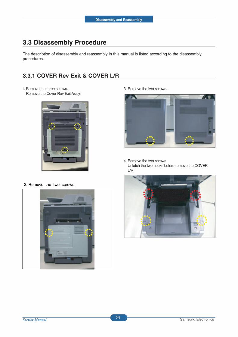
1. Remove the three screws.Remove the Cover Rev Exit Ass’y.
3. Remove the two screws.
4. Remove the two screws.Unlatch the two hooks before remove the COVERL/R
3.3 Disassembly Procedure
The description of disassembly and reassembly in this manual is listed according to the disassembly procedures.
3.3.1 COVER Rev Exit & COVER L/R
mj.song
2. Remove the two screws.
Service Manual
Disassembly and Reassembly
3-6 Samsung Electronics
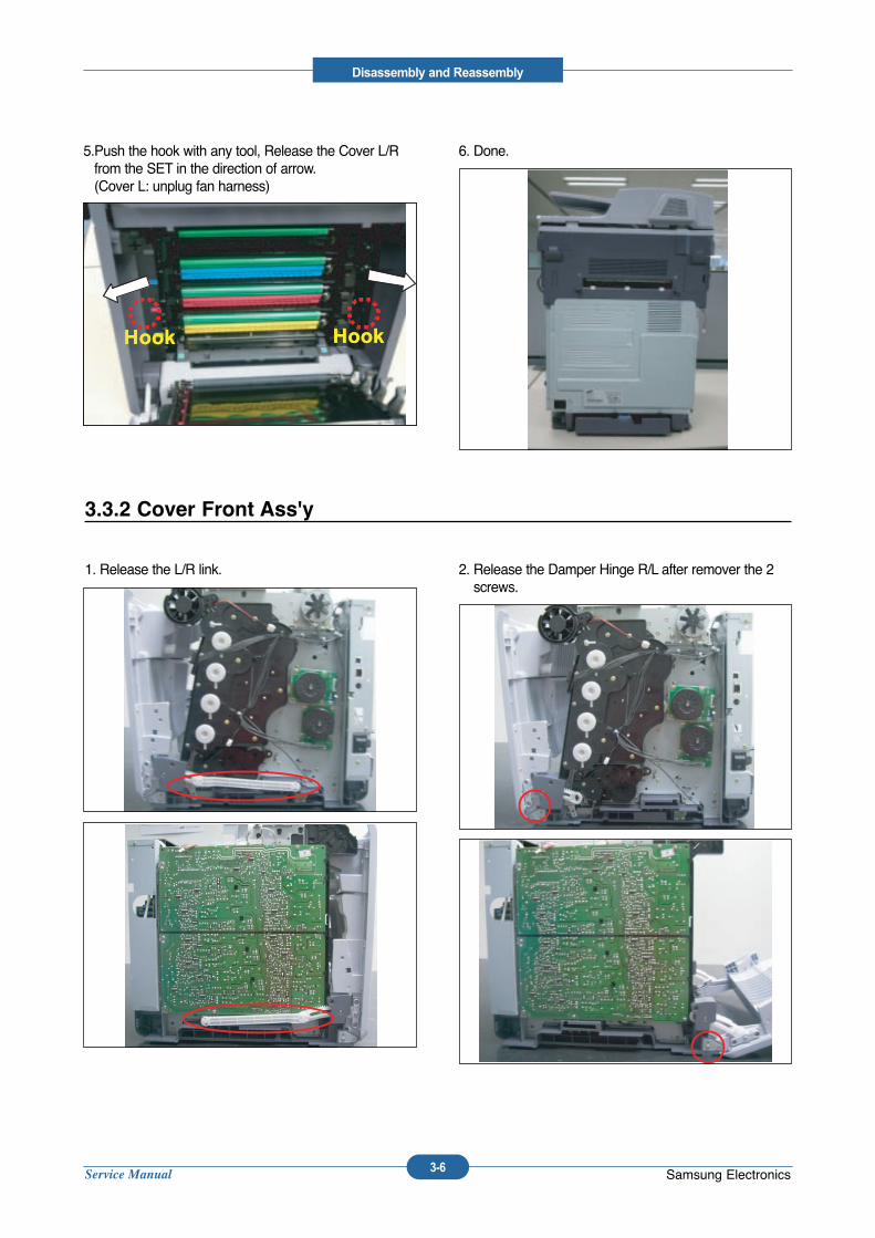
5.Push the hook with any tool, Release the Cover L/Rfrom the SET in the direction of arrow. (Cover L: unplug fan harness)
6. Done.
Hook HookHook HookHook HookHook Hook
1. Release the L/R link. 2. Release the Damper Hinge R/L after remover the 2screws.
3.3.2 Cover Front Ass'y
Service Manual
Disassembly and Reassembly
3-7 Samsung Electronics
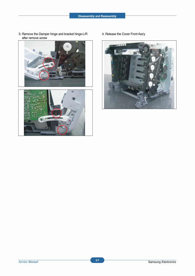
3. Remove the Damper hinge and bracket hinge-L/Rafter remove screw
4. Release the Cover Front Ass'y
Service Manual
Disassembly and Reassembly
3-8 Samsung Electronics
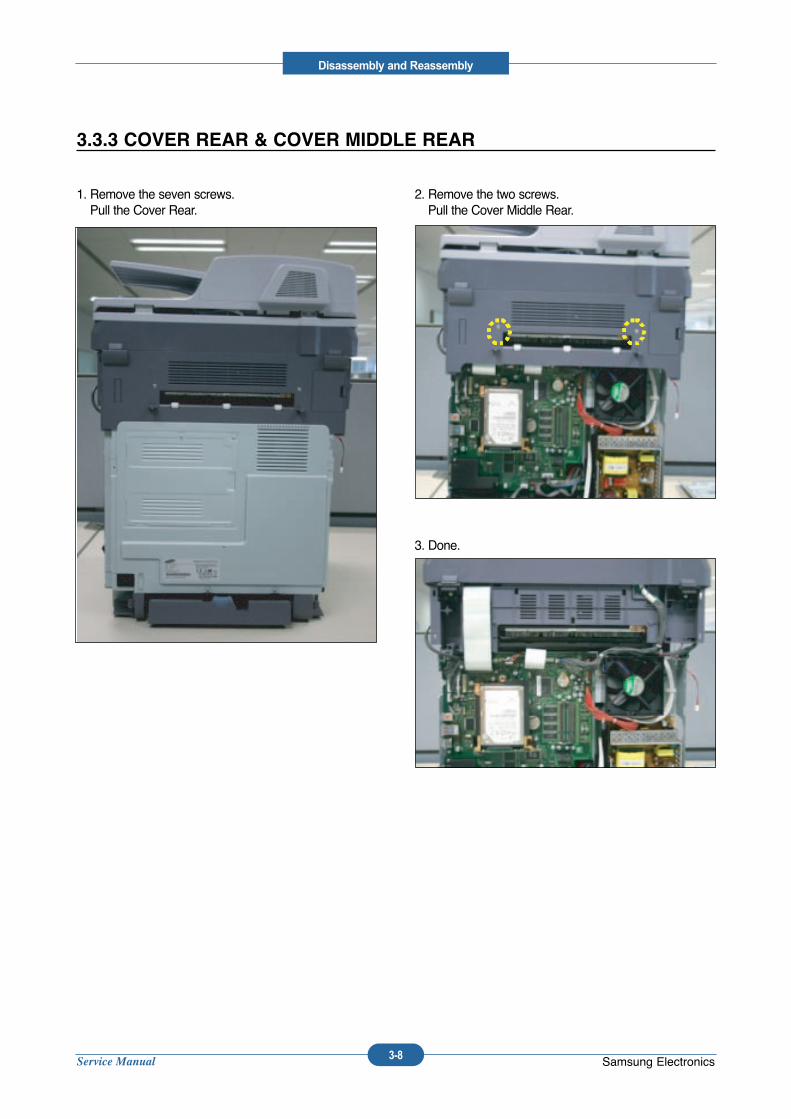
1. Remove the seven screws.Pull the Cover Rear.
2. Remove the two screws.Pull the Cover Middle Rear.
3. Done.
3.3.3 COVER REAR & COVER MIDDLE REAR
Service Manual
Disassembly and Reassembly
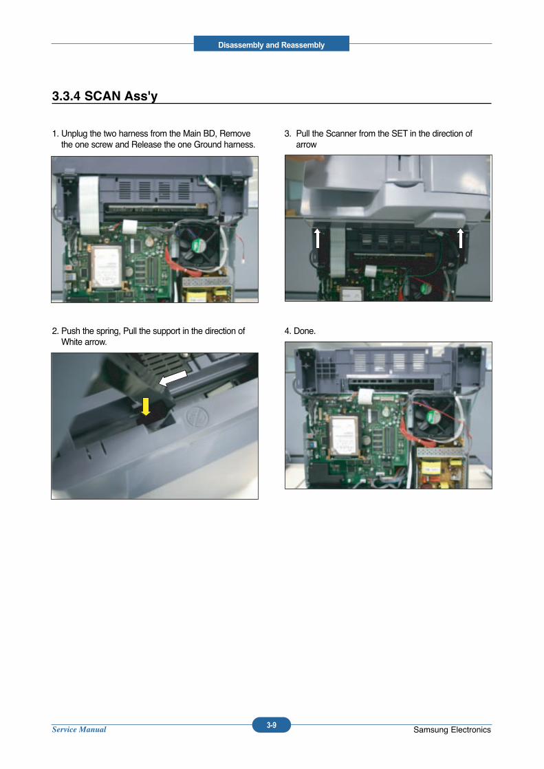
3-9 Samsung Electronics
1. Unplug the two harness from the Main BD, Removethe one screw and Release the one Ground harness.
2. Push the spring, Pull the support in the direction ofWhite arrow.
3. Pull the Scanner from the SET in the direction ofarrow
4. Done.
3.3.4 SCAN Ass'y
Service Manual
Disassembly and Reassembly
3-10 Samsung Electronics
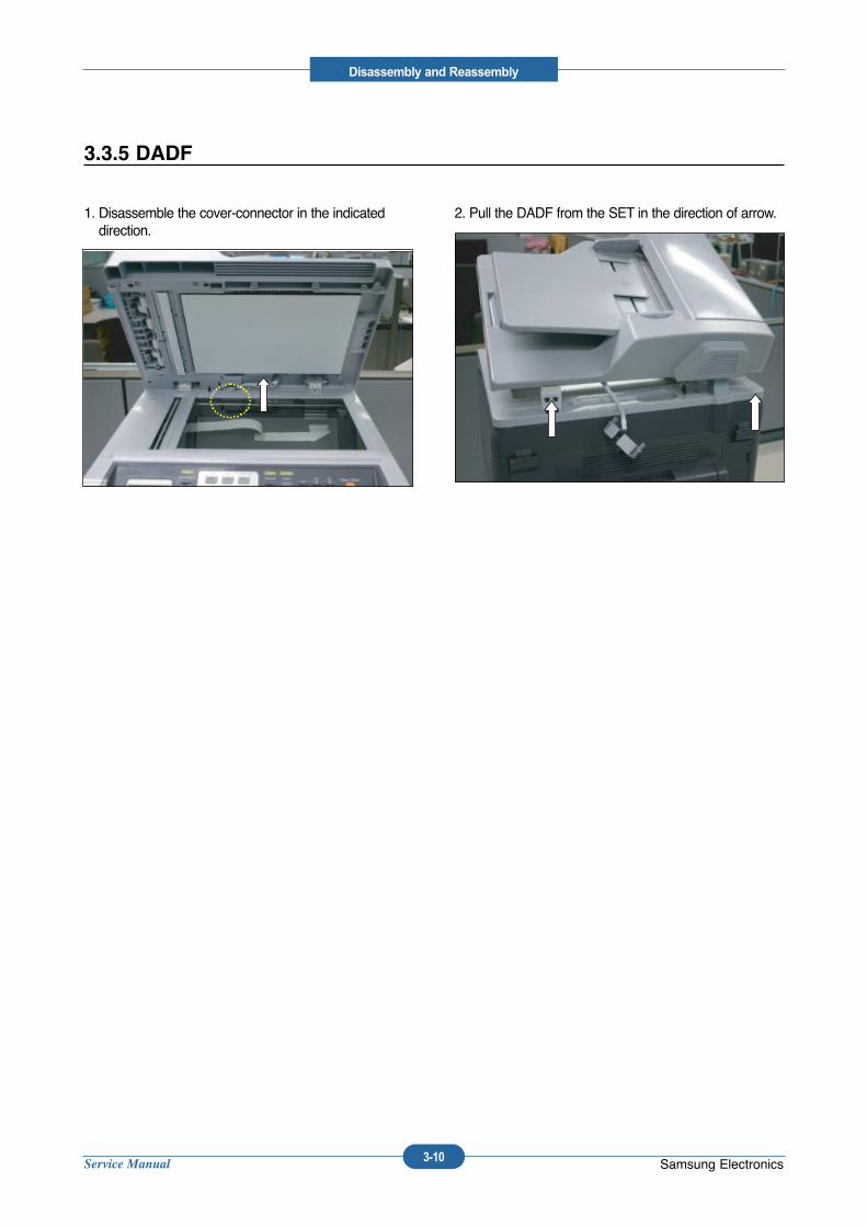
1. Disassemble the cover-connector in the indicateddirection.
2. Pull the DADF from the SET in the direction of arrow.
3.3.5 DADF
Service Manual
Disassembly and Reassembly
3-11 Samsung Electronics
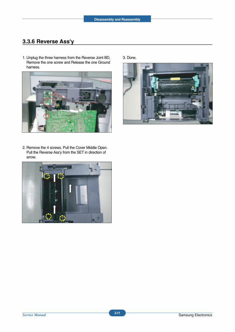
1. Unplug the three harness from the Reverse Joint BD,Remove the one screw and Release the one Groundharness.
2. Remove the 4 screws. Pull the Cover Middle Open.Pull the Reverse Ass'y from the SET in direction ofarrow.
3. Done.
3.3.6 Reverse Ass'y
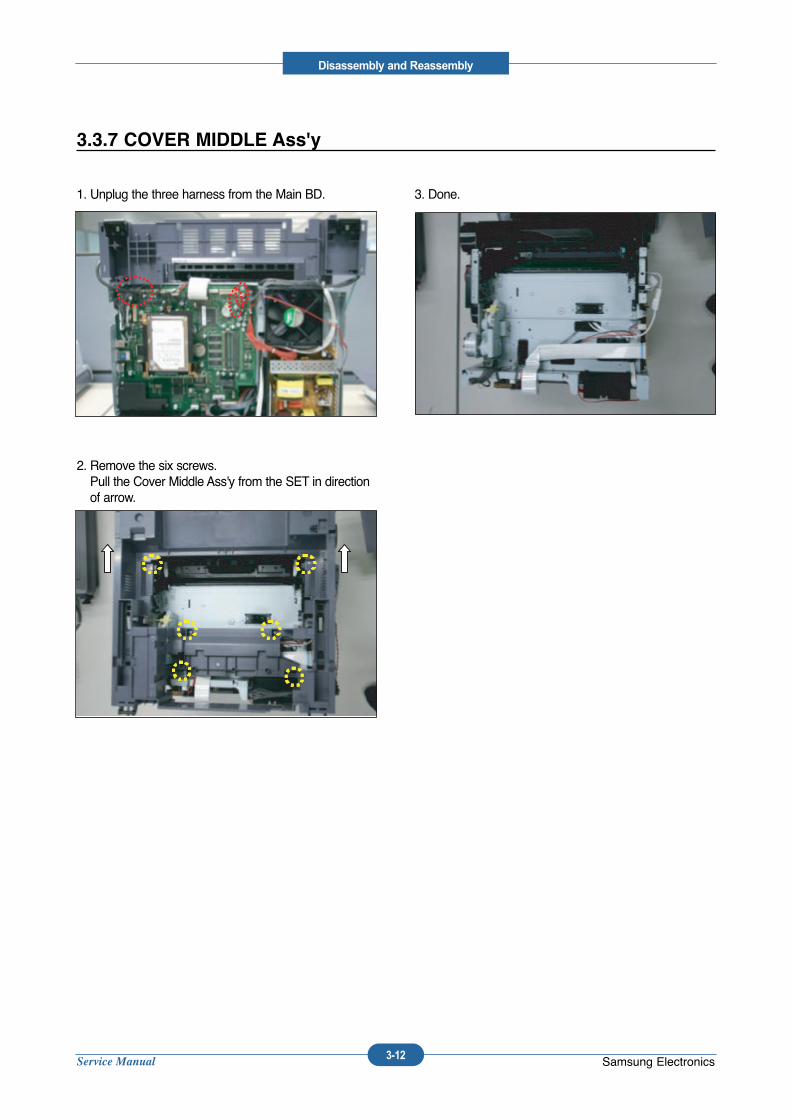
Service Manual
Disassembly and Reassembly
3-12 Samsung Electronics
1. Unplug the three harness from the Main BD.
2. Remove the six screws.Pull the Cover Middle Ass'y from the SET in directionof arrow.
3. Done.
3.3.7 COVER MIDDLE Ass'y
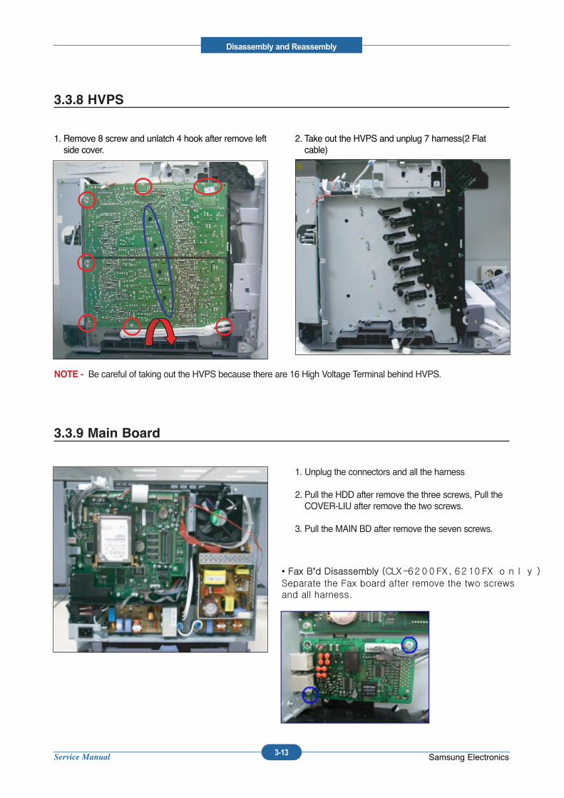
Service Manual
Disassembly and Reassembly
3-13 Samsung Electronics
1. Remove 8 screw and unlatch 4 hook after remove leftside cover.
2. Take out the HVPS and unplug 7 harness(2 Flatcable)
NOTE - Be careful of taking out the HVPS because there are 16 High Voltage Terminal behind HVPS.
3.3.8 HVPS
1. Unplug the connectors and all the harness
2. Pull the HDD after remove the three screws, Pull theCOVER-LIU after remove the two screws.
3. Pull the MAIN BD after remove the seven screws.
3.3.9 Main Board
• Fax B’d Disassembly (CLX-6200FX,6210FX only)Separate the Fax board after remove the two screwsand all harness.
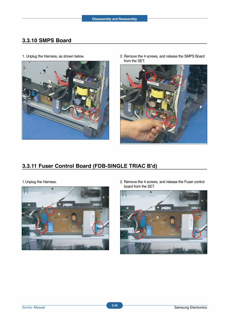
Service Manual
Disassembly and Reassembly
3-14 Samsung Electronics
1. Unplug the Harness, as shown below. 2. Remove the 4 screws, and release the SMPS Boardfrom the SET.
3.3.10 SMPS Board
1.Unplug the Harness. 2. Remove the 4 screws, and release the Fuser controlboard from the SET.
3.3.11 Fuser Control Board (FDB-SINGLE TRIAC B'd)
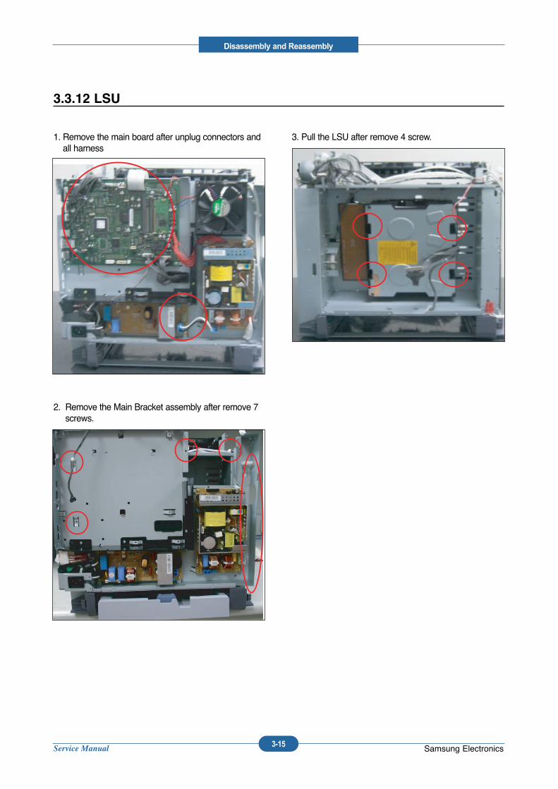
Service Manual
Disassembly and Reassembly
3-15 Samsung Electronics
1. Remove the main board after unplug connectors andall harness
2. Remove the Main Bracket assembly after remove 7screws.
3. Pull the LSU after remove 4 screw.
3.3.12 LSU
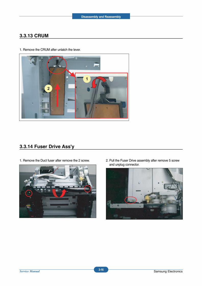
Service Manual
Disassembly and Reassembly
3-16 Samsung Electronics
1. Remove the CRUM after unlatch the lever.
3.3.13 CRUM
1
2
1
2
1. Remove the Duct fuser after remove the 2 screw. 2. Pull the Fuser Drive assembly after remove 5 screwand unplug connector.
3.3.14 Fuser Drive Ass'y
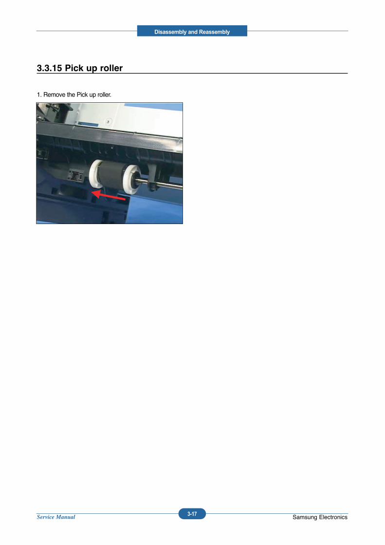
Service Manual
Disassembly and Reassembly
3-17 Samsung Electronics
1. Remove the Pick up roller.
3.3.15 Pick up roller
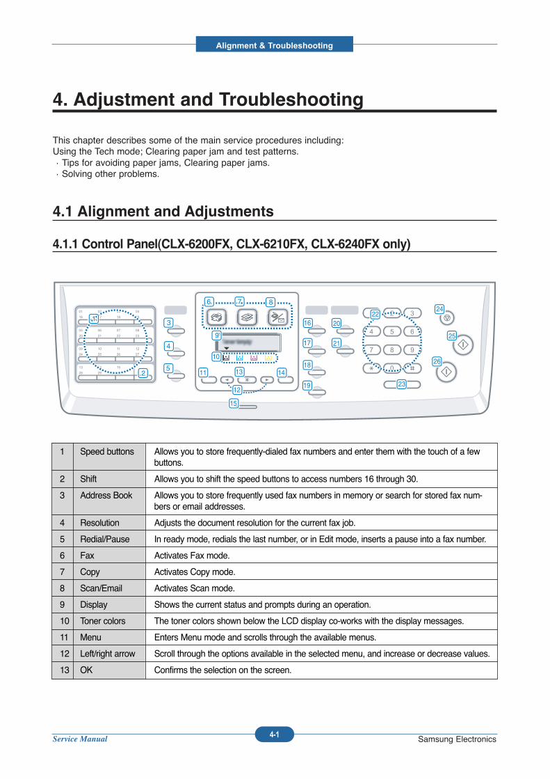
Service Manual
Alignment & Troubleshooting
4-1 Samsung Electronics
4. Adjustment and Troubleshooting
This chapter describes some of the main service procedures including:Using the Tech mode; Clearing paper jam and test patterns.Tips for avoiding paper jams, Clearing paper jams.Solving other problems.
4.1 Alignment and Adjustments
4.1.1 Control Panel(CLX-6200FX, CLX-6210FX, CLX-6240FX only)
1 Speed buttons Allows you to store frequently-dialed fax numbers and enter them with the touch of a fewbuttons.
2 Shift Allows you to shift the speed buttons to access numbers 16 through 30.
3 Address Book Allows you to store frequently used fax numbers in memory or search for stored fax num-bers or email addresses.
4 Resolution Adjusts the document resolution for the current fax job.
5 Redial/Pause In ready mode, redials the last number, or in Edit mode, inserts a pause into a fax number.
6 Fax Activates Fax mode.
7 Copy Activates Copy mode.
8 Scan/Email Activates Scan mode.
9 Display Shows the current status and prompts during an operation.
10 Toner colors The toner colors shown below the LCD display co-works with the display messages.
11 Menu Enters Menu mode and scrolls through the available menus.
12 Left/right arrow Scroll through the options available in the selected menu, and increase or decrease values.
13 OK Confirms the selection on the screen.
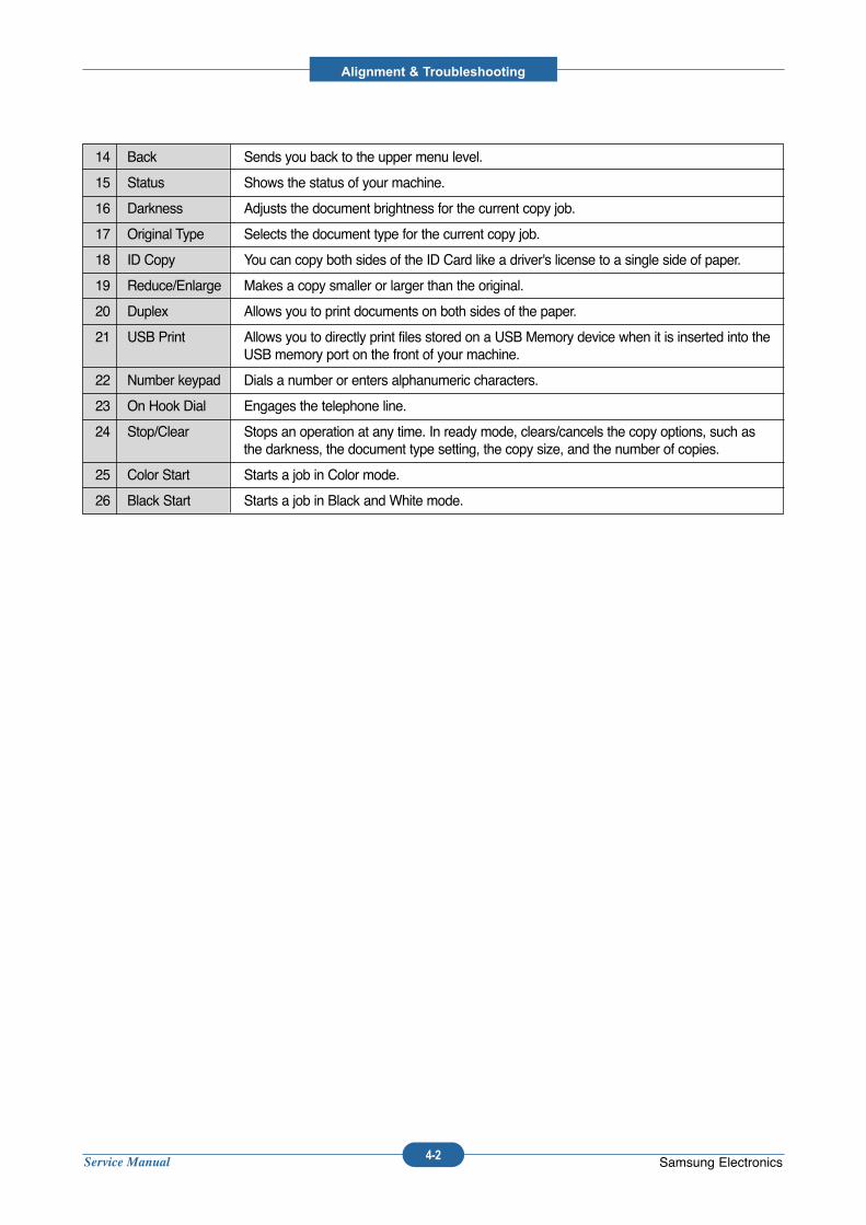
Service Manual
Alignment & Troubleshooting
4-2 Samsung Electronics
14 Back Sends you back to the upper menu level.
15 Status Shows the status of your machine.
16 Darkness Adjusts the document brightness for the current copy job.
17 Original Type Selects the document type for the current copy job.
18 ID Copy You can copy both sides of the ID Card like a driver's license to a single side of paper.
19 Reduce/Enlarge Makes a copy smaller or larger than the original.
20 Duplex Allows you to print documents on both sides of the paper.
21 USB Print Allows you to directly print files stored on a USB Memory device when it is inserted into theUSB memory port on the front of your machine.
22 Number keypad Dials a number or enters alphanumeric characters.
23 On Hook Dial Engages the telephone line.
24 Stop/Clear Stops an operation at any time. In ready mode, clears/cancels the copy options, such asthe darkness, the document type setting, the copy size, and the number of copies.
25 Color Start Starts a job in Color mode.
26 Black Start Starts a job in Black and White mode.
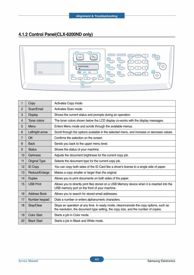
Service Manual
Alignment & Troubleshooting
4-3 Samsung Electronics
1 Copy Activates Copy mode.
2 Scan/Email Activates Scan mode.
3 Display Shows the current status and prompts during an operation.
4 Toner colors The toner colors shown below the LCD display co-works with the display messages.
5 Menu Enters Menu mode and scrolls through the available menus.
6 Left/right arrow Scroll through the options available in the selected menu, and increase or decrease values.
7 OK Confirms the selection on the screen.
8 Back Sends you back to the upper menu level.
9 Status Shows the status of your machine.
10 Darkness Adjusts the document brightness for the current copy job.
11 Original Type Selects the document type for the current copy job.
12 ID Copy You can copy both sides of the ID Card like a driver's license to a single side of paper.
13 Reduce/Enlarge Makes a copy smaller or larger than the original.
14 Duplex Allows you to print documents on both sides of the paper.
15 USB Print Allows you to directly print files stored on a USB Memory device when it is inserted into theUSB memory port on the front of your machine.
16 Address Book Allows you to search for stored email addresses.
17 Number keypad Dials a number or enters alphanumeric characters.
18 Stop/Clear Stops an operation at any time. In ready mode, clears/cancels the copy options, such asthe resolution, the document type setting, the copy size, and the number of copies.
19 Color Start Starts a job in Color mode.
20 Black Start Starts a job in Black and White mode.
4.1.2 Control Panel(CLX-6200ND only)
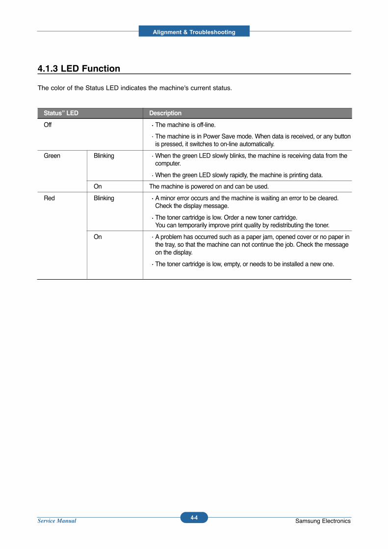
Service Manual
Alignment & Troubleshooting
4-4 Samsung Electronics
4.1.3 LED Function
The color of the Status LED indicates the machine's current status.
Status” LED Description
Off The machine is off-line.
The machine is in Power Save mode. When data is received, or any buttonis pressed, it switches to on-line automatically.
Green Blinking When the green LED slowly blinks, the machine is receiving data from thecomputer.
When the green LED slowly rapidly, the machine is printing data.
On The machine is powered on and can be used.
Red Blinking Aminor error occurs and the machine is waiting an error to be cleared.Check the display message.
The toner cartridge is low. Order a new toner cartridge.You can temporarily improve print quality by redistributing the toner.
On A problem has occurred such as a paper jam, opened cover or no paper inthe tray, so that the machine can not continue the job. Check the messageon the display.
The toner cartridge is low, empty, or needs to be installed a new one.
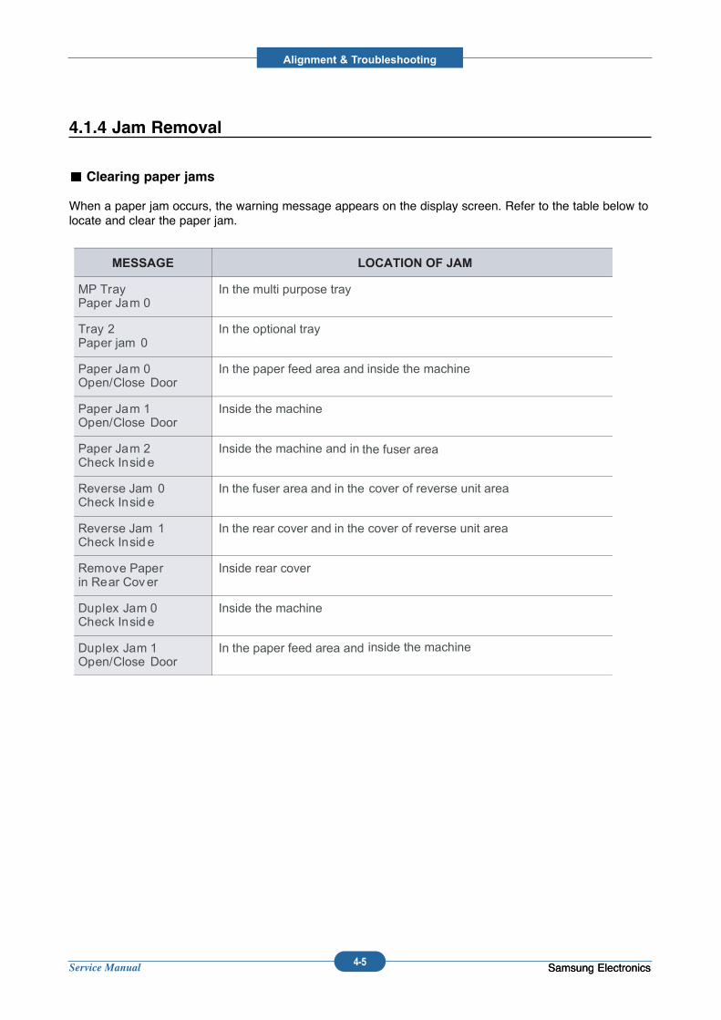
Service Manual
Alignment & Troubleshooting
4-5 Samsung ElectronicsSamsung Electronics
4.1.4 Jam Removal
Clearing paper jams
When a paper jam occurs, the warning message appears on the display screen. Refer to the table below tolocate and clear the paper jam.
MESSAGE LOCATION OF JAM
MP Tray Paper Jam 0
In the multi purpose tray
Tray 2 Paper jam 0
In the optional tray
Paper Jam 0Open/Close Door
In the paper feed area and inside the machine
Paper Jam 1Open/Close Door
Inside the machine
Paper Jam 2Check Insid e
Inside the machine and in the fuser area
Reverse Jam 0Check Insid e
In the fuser area and in the cover of reverse unit area
Reverse Jam 1 Check Insid e
In the rear cover and in the cover of reverse unit area
Remove Paperin Rear Cover
Inside rear cover
Duplex Jam 0Check Insid e
Inside the machine
Duplex Jam 1Open/Close Door
In the paper feed area and inside the machine
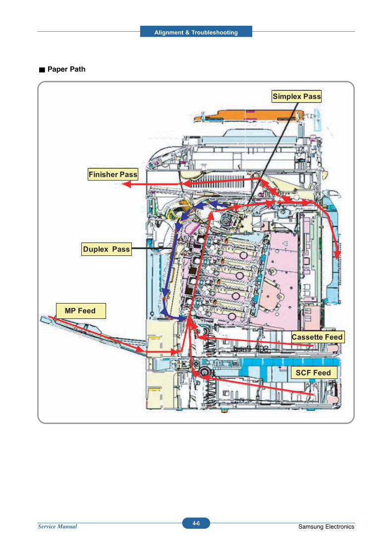
Service Manual
Alignment & Troubleshooting
4-6 Samsung Electronics
Paper Path
Simplex Pass
Finisher Pass
Duplex Pass
MP Feed
SCF Feed
Cassette Feed
Simplex Pass
Finisher Pass
Duplex Pass
MP Feed
SCF Feed
Cassette Feed
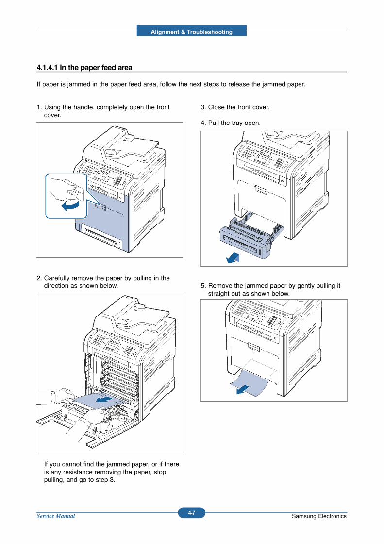
Service Manual
Alignment & Troubleshooting
4-7 Samsung Electronics
1. Using the handle, completely open the frontcover.
2. Carefully remove the paper by pulling in thedirection as shown below.
If you cannot find the jammed paper, or if thereis any resistance removing the paper, stoppulling, and go to step 3.
3. Close the front cover.
4. Pull the tray open.
5. Remove the jammed paper by gently pulling itstraight out as shown below.
4.1.4.1 In the paper feed area
If paper is jammed in the paper feed area, follow the next steps to release the jammed paper.
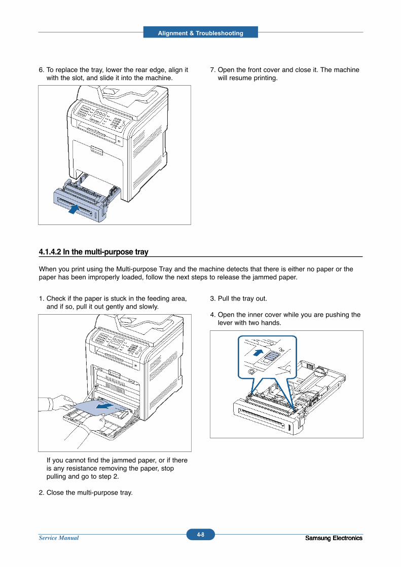
Service Manual
Alignment & Troubleshooting
4-8 Samsung ElectronicsSamsung ElectronicsSamsung ElectronicsSamsung Electronics
6. To replace the tray, lower the rear edge, align itwith the slot, and slide it into the machine.
7. Open the front cover and close it. The machinewill resume printing.
1. Check if the paper is stuck in the feeding area,and if so, pull it out gently and slowly.
If you cannot find the jammed paper, or if thereis any resistance removing the paper, stoppulling and go to step 2.
2. Close the multi-purpose tray.
3. Pull the tray out.
4. Open the inner cover while you are pushing thelever with two hands.
4.1.4.2 In the multi-purpose tray
When you print using the Multi-purpose Tray and the machine detects that there is either no paper or thepaper has been improperly loaded, follow the next steps to release the jammed paper.
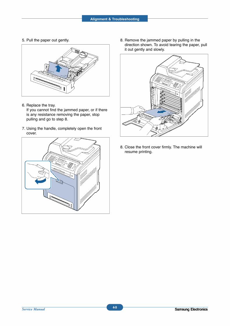
Service Manual
Alignment & Troubleshooting
4-9 Samsung ElectronicsSamsung ElectronicsSamsung ElectronicsSamsung Electronics
5. Pull the paper out gently.
6. Replace the tray.If you cannot find the jammed paper, or if thereis any resistance removing the paper, stoppulling and go to step 8.
7. Using the handle, completely open the frontcover.
8. Remove the jammed paper by pulling in thedirection shown. To avoid tearing the paper, pullit out gently and slowly.
8. Close the front cover firmly. The machine willresume printing.
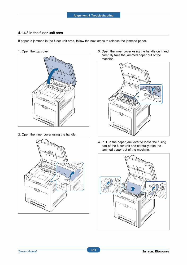
Service Manual
Alignment & Troubleshooting
4-10 Samsung ElectronicsSamsung ElectronicsSamsung ElectronicsSamsung Electronics
1. Open the top cover.
2. Open the inner cover using the handle.
3. Open the inner cover using the handle on it andcarefully take the jammed paper out of themachine.
4. Pull up the paper jam lever to loose the fusingpart of the fuser unit and carefully take thejammed paper out of the machine.
4.1.4.3 In the fuser unit area
If paper is jammed in the fuser unit area, follow the next steps to release the jammed paper.
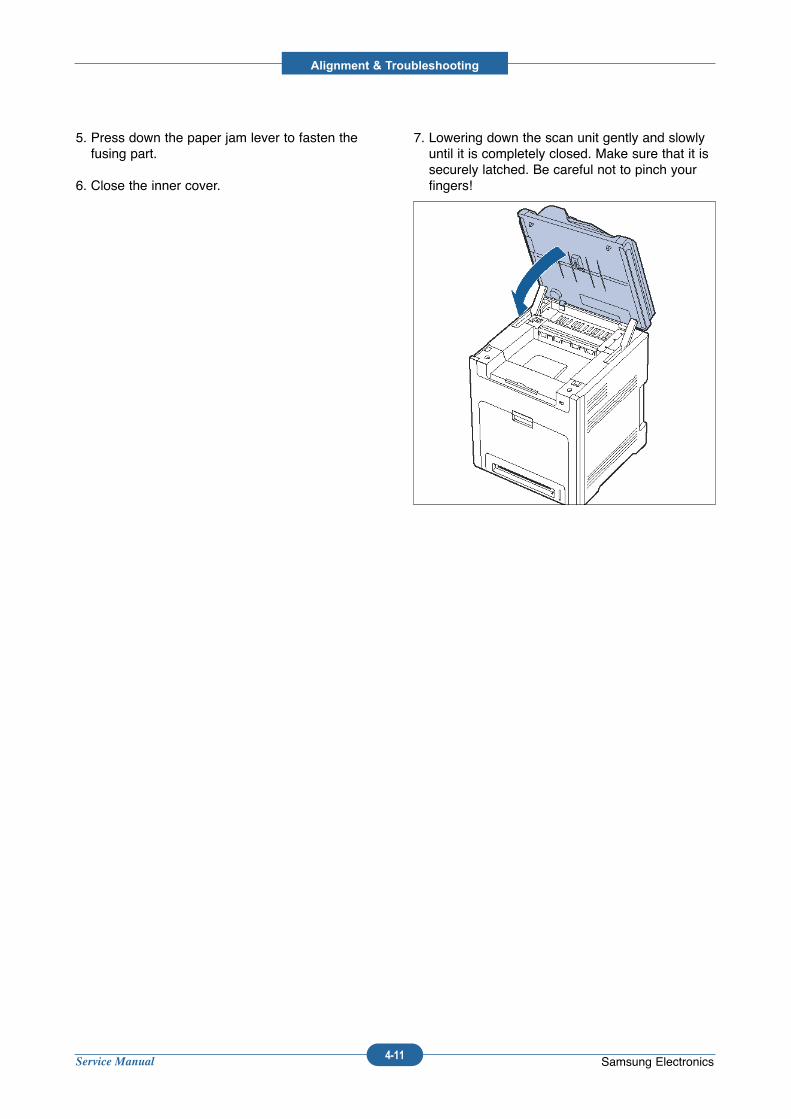
Service Manual
Alignment & Troubleshooting
4-11 Samsung Electronics
5. Press down the paper jam lever to fasten thefusing part.
6. Close the inner cover.
7. Lowering down the scan unit gently and slowlyuntil it is completely closed. Make sure that it issecurely latched. Be careful not to pinch yourfingers!
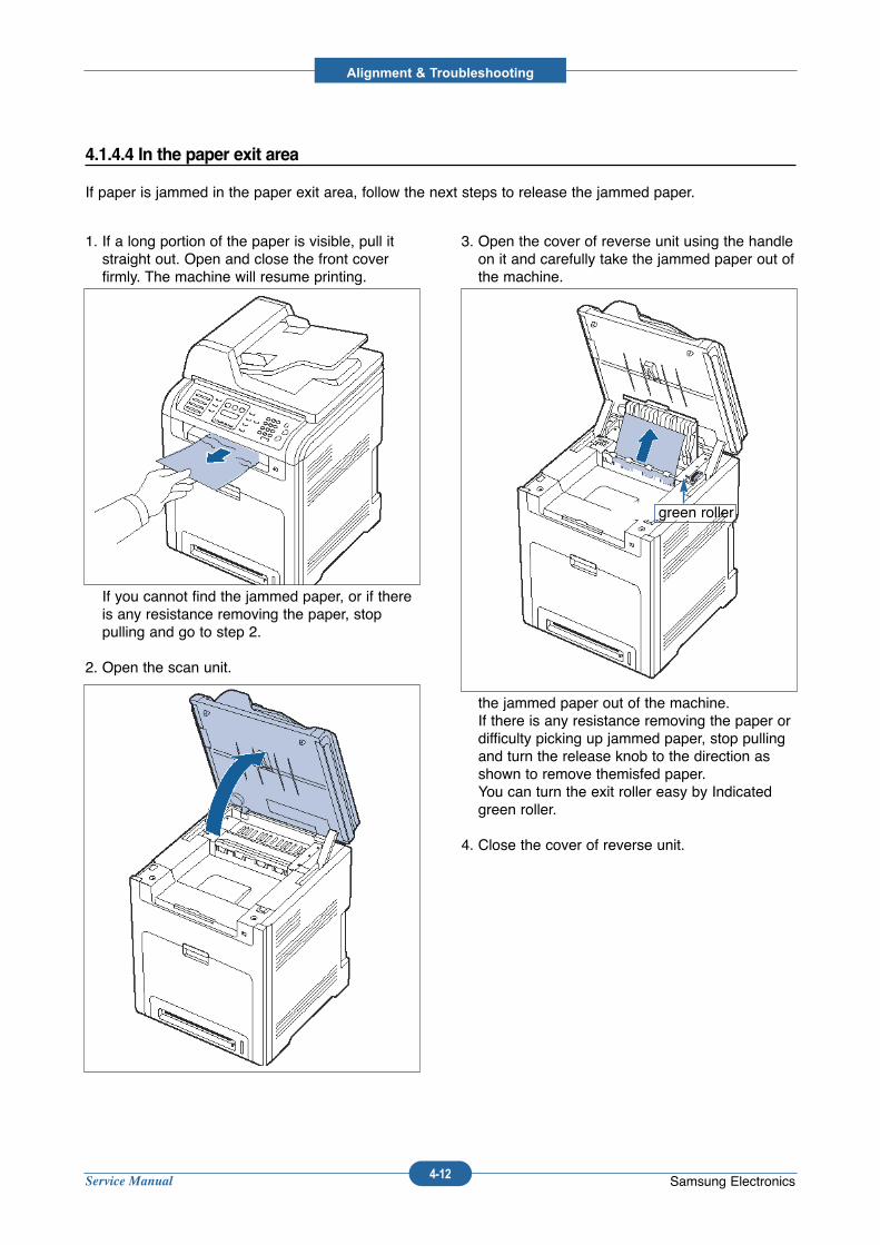
Service Manual
Alignment & Troubleshooting
4-12 Samsung Electronics
1. If a long portion of the paper is visible, pull itstraight out. Open and close the front coverfirmly. The machine will resume printing.
If you cannot find the jammed paper, or if thereis any resistance removing the paper, stoppulling and go to step 2.
2. Open the scan unit.
3. Open the cover of reverse unit using the handleon it and carefully take the jammed paper out ofthe machine.
the jammed paper out of the machine.If there is any resistance removing the paper ordifficulty picking up jammed paper, stop pullingand turn the release knob to the direction asshown to remove themisfed paper.You can turn the exit roller easy by Indicatedgreen roller.
4. Close the cover of reverse unit.
4.1.4.4 In the paper exit area
If paper is jammed in the paper exit area, follow the next steps to release the jammed paper.
green roller
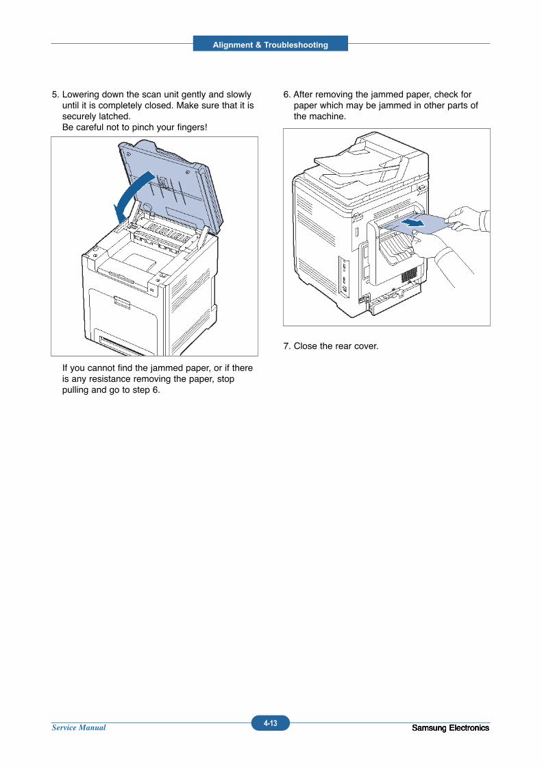
Service Manual
Alignment & Troubleshooting
4-13 Samsung ElectronicsSamsung ElectronicsSamsung ElectronicsSamsung Electronics
5. Lowering down the scan unit gently and slowlyuntil it is completely closed. Make sure that it issecurely latched.Be careful not to pinch your fingers!
If you cannot find the jammed paper, or if thereis any resistance removing the paper, stoppulling and go to step 6.
6. After removing the jammed paper, check forpaper which may be jammed in other parts ofthe machine.
7. Close the rear cover.
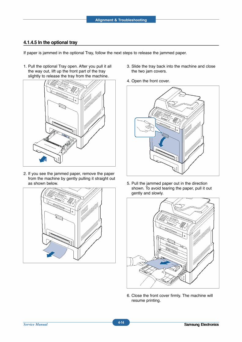
Service Manual
Alignment & Troubleshooting
4-14 Samsung ElectronicsSamsung ElectronicsSamsung ElectronicsSamsung Electronics
1. Pull the optional Tray open. After you pull it allthe way out, lift up the front part of the trayslightly to release the tray from the machine.
2. If you see the jammed paper, remove the paperfrom the machine by gently pulling it straight outas shown below.
3. Slide the tray back into the machine and closethe two jam covers.
4. Open the front cover.
5. Pull the jammed paper out in the directionshown. To avoid tearing the paper, pull it outgently and slowly.
6. Close the front cover firmly. The machine willresume printing.
4.1.4.5 In the optional tray
If paper is jammed in the optional Tray, follow the next steps to release the jammed paper.
Service Manual
Alignment & Troubleshooting
4-15 Samsung ElectronicsSamsung ElectronicsSamsung ElectronicsSamsung ElectronicsSamsung Electronics
4.1.5 System setup
4.1.5.1 Accessing to menus
The next steps are the example to print the menu map of this machine, and they are the general way toselect menu and configure your machine.
1. Make sure your machine is properly connected all the necessary cables, and turn on the machine.
2. Press the Menu button until you see the menu (ex. Information) you want on the bottom line of the dis-play.
3. Press the Enter button to access the menu.
4. Press the Left/right arrow buttons until the menu item (ex. Menu Map) you want displays on the bottomline.
5. Press the OK button to confirm the selected item.
6. Press the Left/right arrow buttons until the menu item (ex. Print?) you want displays on the bottom line.
7. Press the OK button to process your selection, save your input or selection.An asterisk (*) appears next to the selection on the display, indicating that it is now the default.
8. To exit the menu, press the Back button repeatedly, or the Stop button.
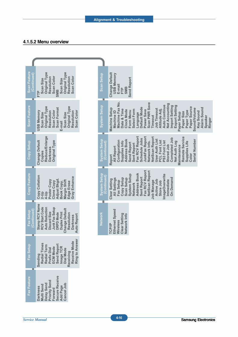
Service Manual
Alignment & Troubleshooting
4-16 Samsung ElectronicsSamsung ElectronicsSamsung ElectronicsSamsung ElectronicsSamsung Electronics
4.1.5.2 Menu overview
Fax Feature
Darkness
Multi Send
Delay Send
Priority Send
Forward
Secure Receive
Add Page
Cancel Job
Fax Setup
Sending
Redial Times
Redial Term
Prefix Dial
ECM Mode
Send Report
Image TCR
Dial Mode
Receiving
Receive Mode
Ring to Answer
Fax Setup
(Continued)
Stamp RCV Name
RCV Start Code
Auto Reduction
Discard Size
Junk Fax Setup
DRPD Mode
Duplex Print
Change Default
Resolution
Darkness
Auto Report
Copy Feature
Copy Collation
2-Up
4-Up
Poster Copy
Clone Copy
Adjust Bkgd.
Book Copy.
Margin Shift
Edge Erase
Gray Enhance
Copy Setup
Change Default
Copies
Reduce/Enlarge
Darkness
Original Type
Scan Feature
USB Memory
Scan Size
Original Type
Resolution
Scan Color
Scan Format
Scan Size
Original Type
Resolution
Scan Color
Scan Feature
(Continued)
FTP Scan Size
Original Type
Resolution
Scan Color
SMB Scan Size
Original Type
Resolution
Scan Color
System Setup
Machine Setup
Machine ID
Machine Fax No.
Date & Time
Clock Mode
Form Menu
Select Form
Language
Default Mode
Power Save
Scan PWR Save
Timeout
Job Timeout
Altitude Adj.
Auto Continue
Net Accounting
Import Setting
Export Setting
Paper Setup
Paper Size
Paper Type
Paper Source
Sound/Volume
Key Sound
Alarm Sound
Speaker
Ringer
System Setup
(Continued)
Report
All Report
Configuration
Supplies Info
Address Book
Send Report
Sent Report
Fax RCV Report
Schedule Jobs
JunkFax Report
Network Info.
NetScan Report
User Auth List
PCL Font List
PS3 Font List
Stored Job
Completed Job
Net Auth Log
Maintenance
Remote Service
Supplies Life
Color
Serial Number
System Setup
(Continued)
Clear Setting
All Settings
Fax Setup
Copy Setup
Scan Setup
System Setup
Network
Address Book
Sent Report
Fax RCV Report
NetScan Report
Job Manage
Active Job
Store Job
ImageOverwrite
Immediate
On Demand
Network
TCP/IP
Ethernet Speed
Wireless
Clear Setting
Network Info
Scan Setup
Change Default
USB Memory
FTP
SMB
Send Report
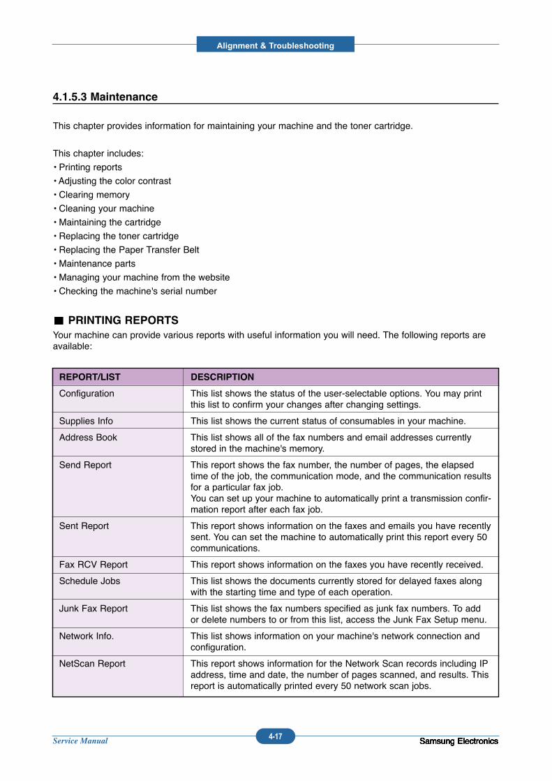
Service Manual
Alignment & Troubleshooting
4-17 Samsung ElectronicsSamsung ElectronicsSamsung ElectronicsSamsung ElectronicsSamsung Electronics
4.1.5.3 Maintenance
This chapter provides information for maintaining your machine and the toner cartridge.
This chapter includes:
• Printing reports
• Adjusting the color contrast
• Clearing memory
• Cleaning your machine
• Maintaining the cartridge
• Replacing the toner cartridge
• Replacing the Paper Transfer Belt
• Maintenance parts
• Managing your machine from the website
• Checking the machine's serial number
PRINTING REPORTS
Your machine can provide various reports with useful information you will need. The following reports areavailable:
REPORT/LIST DESCRIPTION
Configuration This list shows the status of the user-selectable options. You may printthis list to confirm your changes after changing settings.
Supplies Info This list shows the current status of consumables in your machine.
Address Book This list shows all of the fax numbers and email addresses currentlystored in the machine's memory.
Send Report This report shows the fax number, the number of pages, the elapsedtime of the job, the communication mode, and the communication resultsfor a particular fax job.You can set up your machine to automatically print a transmission confir-mation report after each fax job.
Sent Report This report shows information on the faxes and emails you have recentlysent. You can set the machine to automatically print this report every 50communications.
Fax RCV Report This report shows information on the faxes you have recently received.
Schedule Jobs This list shows the documents currently stored for delayed faxes alongwith the starting time and type of each operation.
Junk Fax Report This list shows the fax numbers specified as junk fax numbers. To addor delete numbers to or from this list, access the Junk Fax Setup menu.
Network Info. This list shows information on your machine's network connection andconfiguration.
NetScan Report This report shows information for the Network Scan records including IPaddress, time and date, the number of pages scanned, and results. Thisreport is automatically printed every 50 network scan jobs.
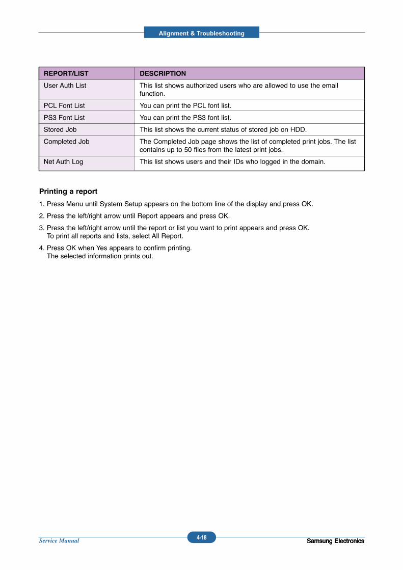
Service Manual
Alignment & Troubleshooting
4-18 Samsung ElectronicsSamsung ElectronicsSamsung ElectronicsSamsung ElectronicsSamsung Electronics
Printing a report
1. Press Menu until System Setup appears on the bottom line of the display and press OK.
2. Press the left/right arrow until Report appears and press OK.
3. Press the left/right arrow until the report or list you want to print appears and press OK.To print all reports and lists, select All Report.
4. Press OK when Yes appears to confirm printing.The selected information prints out.
REPORT/LIST DESCRIPTION
User Auth List This list shows authorized users who are allowed to use the email function.
PCL Font List You can print the PCL font list.
PS3 Font List You can print the PS3 font list.
Stored Job This list shows the current status of stored job on HDD.
Completed Job The Completed Job page shows the list of completed print jobs. The listcontains up to 50 files from the latest print jobs.
Net Auth Log This list shows users and their IDs who logged in the domain.
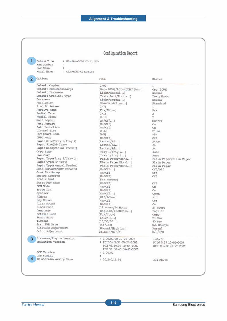
Service Manual
Alignment & Troubleshooting
4-19 Samsung Electronics
2
3
1
4
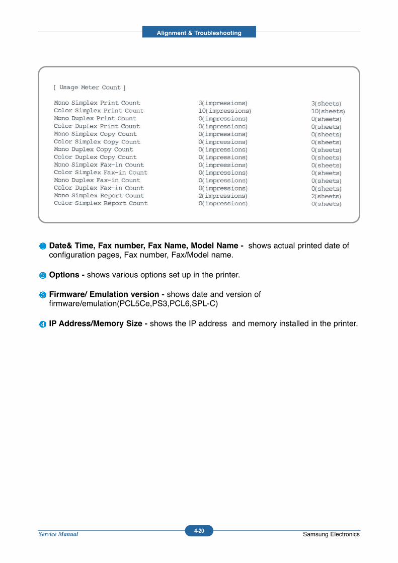
Service Manual
Alignment & Troubleshooting
4-20 Samsung Electronics
Date& Time, Fax number, Fax Name, Model Name - shows actual printed date ofconfiguration pages, Fax number, Fax/Model name.
Options - shows various options set up in the printer.
Firmware/ Emulation version - shows date and version offirmware/emulation(PCL5Ce,PS3,PCL6,SPL-C)
IP Address/Memory Size - shows the IP address and memory installed in the printer.
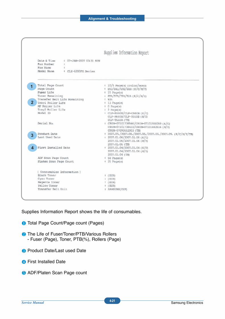
Service Manual
Alignment & Troubleshooting
4-21 Samsung Electronics
1
2
3
4
Supplies Information Report shows the life of consumables.
Total Page Count/Page count (Pages)
The Life of Fuser/Toner/PTB/Various Rollers - Fuser (Page), Toner, PTB(%), Rollers (Page)
Product Date/Last used Date
First Installed Date
ADF/Platen Scan Page count
CLEARING MEMORY
You can selectively clear information stored in your machine's memory.
1. Press Menu until System Setup appears on the bottom line of the display and press OK.
2. Press the left/right arrow until Clear Setting appears and press OK.
3. Press the left/right arrow until the item you want to clear appears.
4. Press OK when Yes appears.
5. Press OK again to confirm clearing.
6. Repeat steps 3 through 5 to clear another item.
7. Press Stop/Clear to return to ready mode.
OPTIONS DESCRIPTION
All Settings Clears all of the data stored in memory and resets all of your settings tothe factory default.
Fax Setup Restores all of the fax options to the factory default.
Copy Setup Restores all of the copy options to the factory default.
Scan Setup Restores all of the scan options to the factory default.
System Setup Restores all of the system options to the factory default.
Network Restores all of the network options to the factory default.
Address Book Clears all of the fax number and email address entries stored in memory.
Sent Report Clears all records of sent faxes and emails.
Fax RCV Report Clears all records of received faxes.
NetScan Report Clears the information on network scan sessions in memory.
Service Manual
Alignment & Troubleshooting
4-22 Samsung Electronics
ADJUSTING THE COLOR CONTRAST
Color menu allows you to adjust the color setting.
1. Press Menu until System Setup appears on the bottom line of the display and press OK.
2. Press OK when Maintenance appears.
3. Press the left/right arrow until Color appears and press OK.
4. Press the left/right arrow until the menu you want appears on display and press OK.
• Custom C olor:Allows you to adjust contrast color by color. Default optimizes color automatically.Manual Adjust allows you to manually adjust the color contrast for each cartridge. Default setting is rec-ommended for getting best color quality.
• Auto Color Reg.: Allows you to adjust the position of print color texts or graphics to match the originalfile on your screen.
5. Press Stop/Clear to return to ready mode.
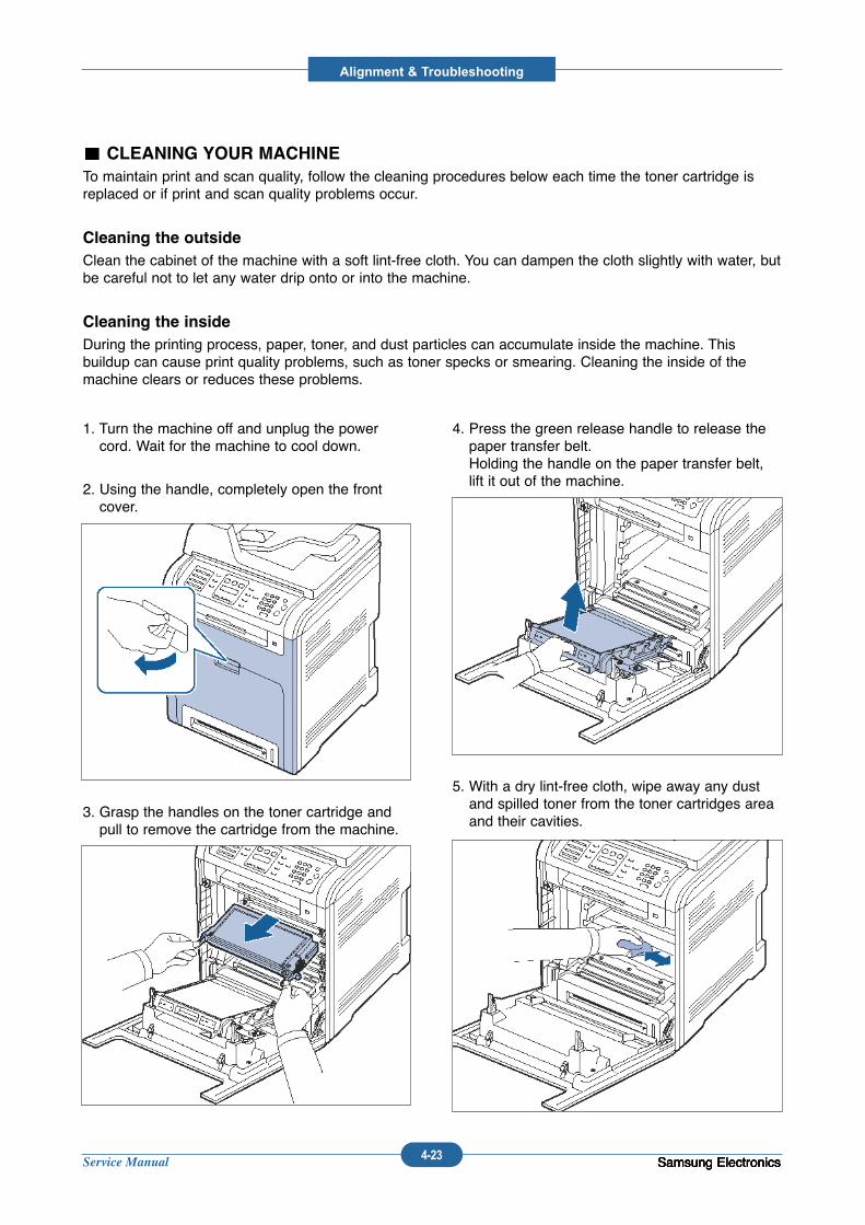
Service Manual
Alignment & Troubleshooting
4-23 Samsung ElectronicsSamsung ElectronicsSamsung ElectronicsSamsung Electronics
CLEANING YOUR MACHINE
To maintain print and scan quality, follow the cleaning procedures below each time the toner cartridge isreplaced or if print and scan quality problems occur.
Cleaning the outside
Clean the cabinet of the machine with a soft lint-free cloth. You can dampen the cloth slightly with water, butbe careful not to let any water drip onto or into the machine.
Cleaning the inside
During the printing process, paper, toner, and dust particles can accumulate inside the machine. Thisbuildup can cause print quality problems, such as toner specks or smearing. Cleaning the inside of themachine clears or reduces these problems.
1. Turn the machine off and unplug the powercord. Wait for the machine to cool down.
2. Using the handle, completely open the frontcover.
3. Grasp the handles on the toner cartridge andpull to remove the cartridge from the machine.
4. Press the green release handle to release thepaper transfer belt. Holding the handle on the paper transfer belt,lift it out of the machine.
5. With a dry lint-free cloth, wipe away any dustand spilled toner from the toner cartridges areaand their cavities.
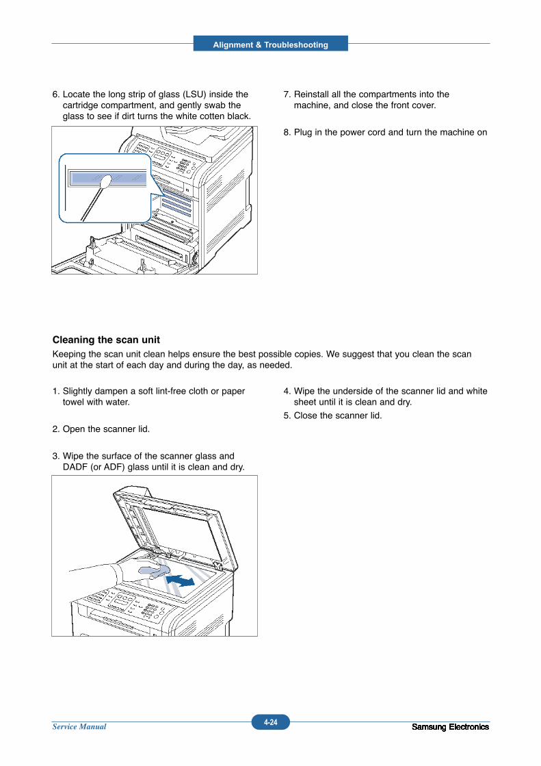
Service Manual
Alignment & Troubleshooting
4-24 Samsung ElectronicsSamsung ElectronicsSamsung ElectronicsSamsung ElectronicsSamsung ElectronicsSamsung ElectronicsSamsung ElectronicsSamsung Electronics
6. Locate the long strip of glass (LSU) inside thecartridge compartment, and gently swab theglass to see if dirt turns the white cotten black.
7. Reinstall all the compartments into themachine, and close the front cover.
8. Plug in the power cord and turn the machine on
Cleaning the scan unit
Keeping the scan unit clean helps ensure the best possible copies. We suggest that you clean the scanunit at the start of each day and during the day, as needed.
1. Slightly dampen a soft lint-free cloth or papertowel with water.
2. Open the scanner lid.
3. Wipe the surface of the scanner glass andDADF (or ADF) glass until it is clean and dry.
4. Wipe the underside of the scanner lid and whitesheet until it is clean and dry.
5. Close the scanner lid.
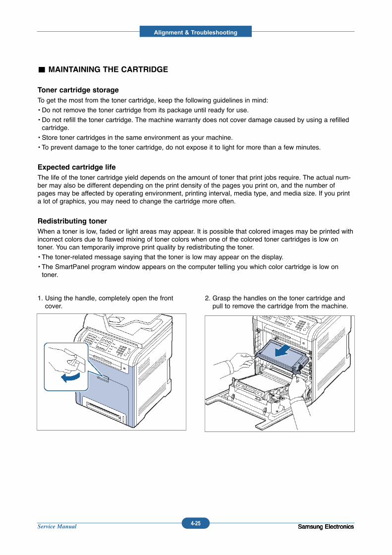
Service Manual
Alignment & Troubleshooting
4-25 Samsung ElectronicsSamsung ElectronicsSamsung ElectronicsSamsung Electronics
MAINTAINING THE CARTRIDGE
Toner cartridge storage
To get the most from the toner cartridge, keep the following guidelines in mind:
• Do not remove the toner cartridge from its package until ready for use.
• Do not refill the toner cartridge. The machine warranty does not cover damage caused by using a refilledcartridge.
• Store toner cartridges in the same environment as your machine.
• To prevent damage to the toner cartridge, do not expose it to light for more than a few minutes.
Expected cartridge life
The life of the toner cartridge yield depends on the amount of toner that print jobs require. The actual num-ber may also be different depending on the print density of the pages you print on, and the number ofpages may be affected by operating environment, printing interval, media type, and media size. If you printa lot of graphics, you may need to change the cartridge more often.
Redistributing toner
When a toner is low, faded or light areas may appear. It is possible that colored images may be printed withincorrect colors due to flawed mixing of toner colors when one of the colored toner cartridges is low ontoner. You can temporarily improve print quality by redistributing the toner.
• The toner-related message saying that the toner is low may appear on the display.
• The SmartPanel program window appears on the computer telling you which color cartridge is low ontoner.
1. Using the handle, completely open the frontcover.
2. Grasp the handles on the toner cartridge andpull to remove the cartridge from the machine.
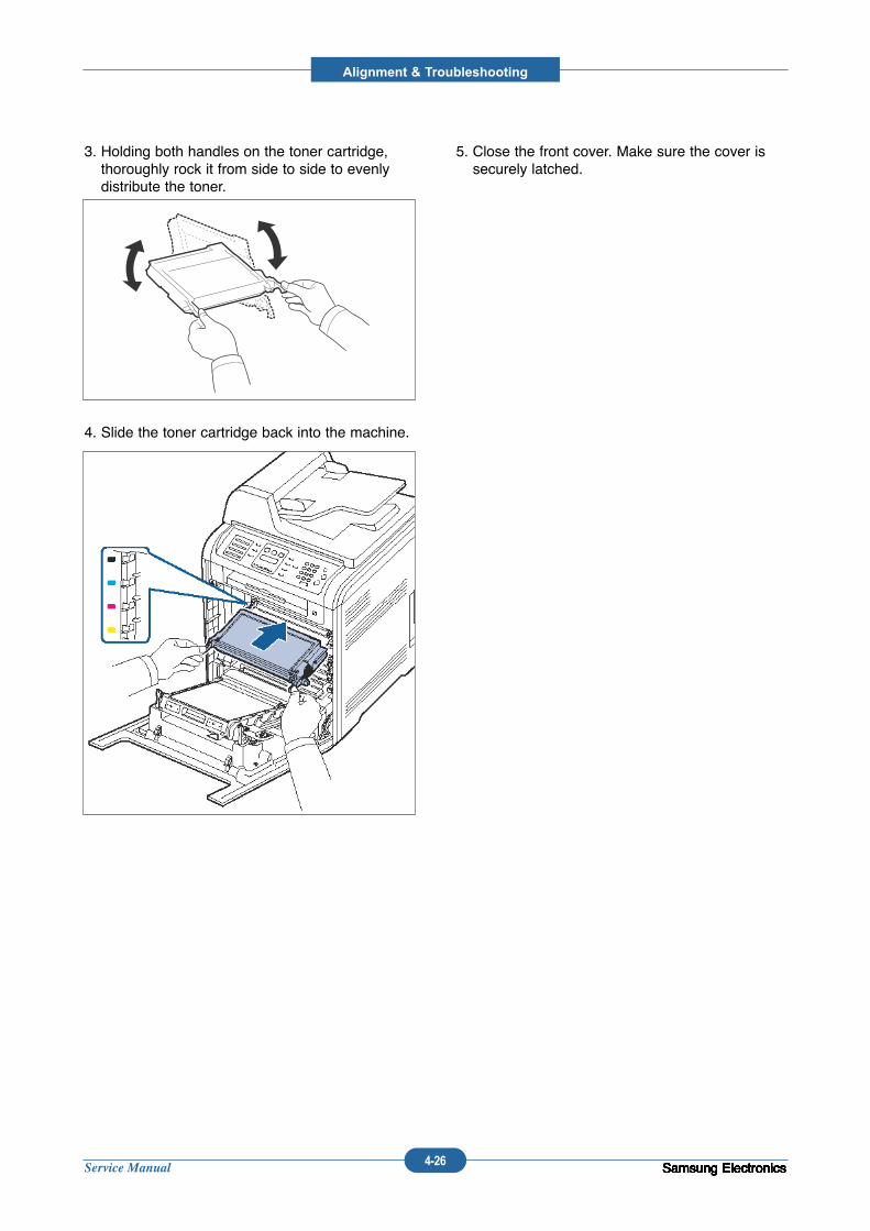
Service Manual
Alignment & Troubleshooting
4-26 Samsung ElectronicsSamsung ElectronicsSamsung ElectronicsSamsung ElectronicsSamsung ElectronicsSamsung ElectronicsSamsung ElectronicsSamsung ElectronicsSamsung Electronics
3. Holding both handles on the toner cartridge,thoroughly rock it from side to side to evenlydistribute the toner.
4. Slide the toner cartridge back into the machine.
5. Close the front cover. Make sure the cover issecurely latched.
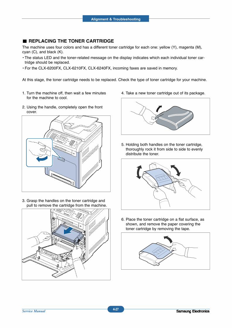
Service Manual
Alignment & Troubleshooting
4-27 Samsung ElectronicsSamsung ElectronicsSamsung ElectronicsSamsung ElectronicsSamsung ElectronicsSamsung ElectronicsSamsung ElectronicsSamsung ElectronicsSamsung Electronics
1. Turn the machine off, then wait a few minutesfor the machine to cool.
2. Using the handle, completely open the frontcover.
3. Grasp the handles on the toner cartridge andpull to remove the cartridge from the machine.
4. Take a new toner cartridge out of its package.
5. Holding both handles on the toner cartridge,thoroughly rock it from side to side to evenlydistribute the toner.
6. Place the toner cartridge on a flat surface, asshown, and remove the paper covering thetoner cartridge by removing the tape.
REPLACING THE TONER CARTRIDGE
The machine uses four colors and has a different toner cartridge for each one: yellow (Y), magenta (M),cyan (C), and black (K).
• The status LED and the toner-related message on the display indicates which each individual toner car-tridge should be replaced.
• For the CLX-6200FX, CLX-6210FX, CLX-6240FX, incoming faxes are saved in memory.
At this stage, the toner cartridge needs to be replaced. Check the type of toner cartridge for your machine.
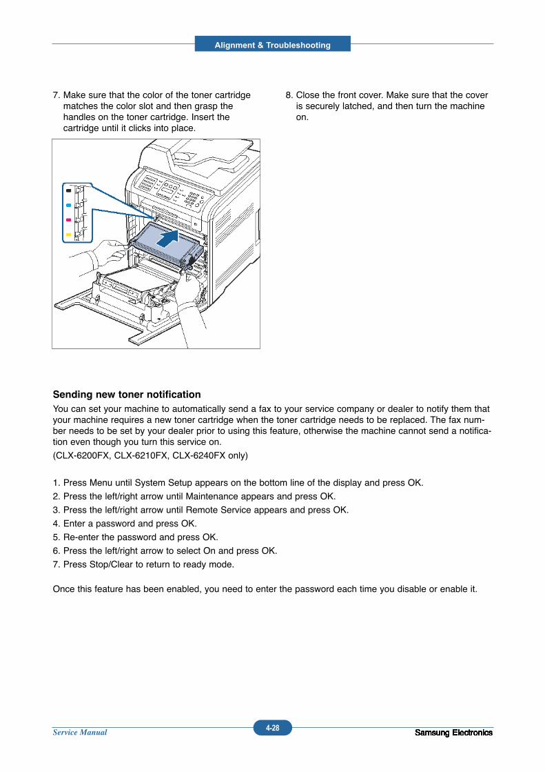
Service Manual
Alignment & Troubleshooting
4-28 Samsung ElectronicsSamsung ElectronicsSamsung ElectronicsSamsung ElectronicsSamsung ElectronicsSamsung ElectronicsSamsung ElectronicsSamsung ElectronicsSamsung Electronics
7. Make sure that the color of the toner cartridgematches the color slot and then grasp the handles on the toner cartridge. Insert the cartridge until it clicks into place.
8. Close the front cover. Make sure that the coveris securely latched, and then turn the machineon.
Sending new toner notification
You can set your machine to automatically send a fax to your service company or dealer to notify them thatyour machine requires a new toner cartridge when the toner cartridge needs to be replaced. The fax num-ber needs to be set by your dealer prior to using this feature, otherwise the machine cannot send a notifica-tion even though you turn this service on.
(CLX-6200FX, CLX-6210FX, CLX-6240FX only)
1. Press Menu until System Setup appears on the bottom line of the display and press OK.
2. Press the left/right arrow until Maintenance appears and press OK.
3. Press the left/right arrow until Remote Service appears and press OK.
4. Enter a password and press OK.
5. Re-enter the password and press OK.
6. Press the left/right arrow to select On and press OK.
7. Press Stop/Clear to return to ready mode.
Once this feature has been enabled, you need to enter the password each time you disable or enable it.
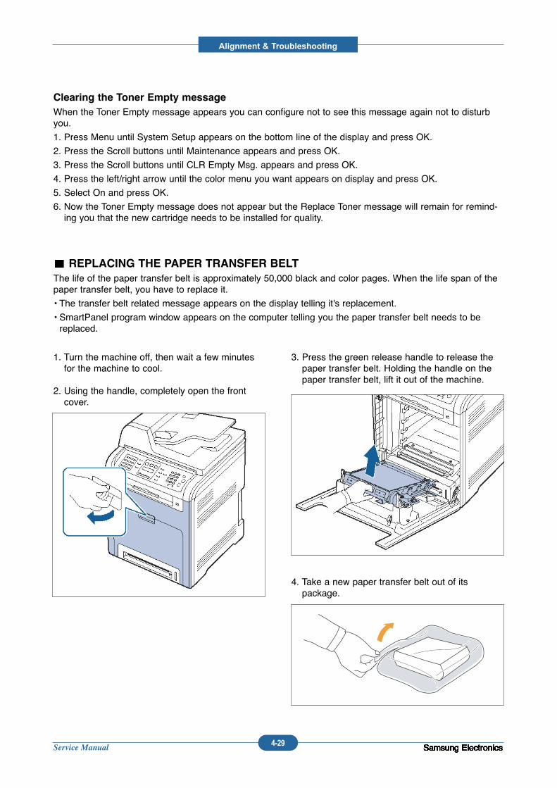
Service Manual
Alignment & Troubleshooting
4-29 Samsung ElectronicsSamsung ElectronicsSamsung ElectronicsSamsung ElectronicsSamsung ElectronicsSamsung ElectronicsSamsung ElectronicsSamsung ElectronicsSamsung Electronics
1. Turn the machine off, then wait a few minutesfor the machine to cool.
2. Using the handle, completely open the frontcover.
3. Press the green release handle to release thepaper transfer belt. Holding the handle on thepaper transfer belt, lift it out of the machine.
4. Take a new paper transfer belt out of its package.
Clearing the Toner Empty message
When the Toner Empty message appears you can configure not to see this message again not to disturbyou.
1. Press Menu until System Setup appears on the bottom line of the display and press OK.
2. Press the Scroll buttons until Maintenance appears and press OK.
3. Press the Scroll buttons until CLR Empty Msg. appears and press OK.
4. Press the left/right arrow until the color menu you want appears on display and press OK.
5. Select On and press OK.
6. Now the Toner Empty message does not appear but the Replace Toner message will remain for remind-ing you that the new cartridge needs to be installed for quality.
REPLACING THE PAPER TRANSFER BELT
The life of the paper transfer belt is approximately 50,000 black and color pages. When the life span of thepaper transfer belt, you have to replace it.
• The transfer belt related message appears on the display telling it's replacement.
• SmartPanel program window appears on the computer telling you the paper transfer belt needs to bereplaced.
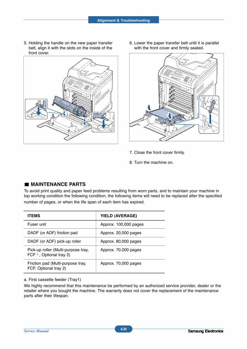
Service Manual
Alignment & Troubleshooting
4-30 Samsung ElectronicsSamsung ElectronicsSamsung ElectronicsSamsung ElectronicsSamsung Electronics
MAINTENANCE PARTS
To avoid print quality and paper feed problems resulting from worn parts, and to maintain your machine intop working condition the following condition, the following items will need to be replaced after the specified
number of pages, or when the life span of each item has expired.
a. First cassette feeder (Tray1)
We highly recommend that this maintenance be performed by an authorized service provider, dealer or theretailer where you bought the machine. The warranty does not cover the replacement of the maintenanceparts after their lifespan.
ITEMS YIELD (AVERAGE)
Fuser unit Approx. 100,000 pages
DADF (or ADF) friction pad Approx. 20,000 pages
DADF (or ADF) pick-up roller Approx. 80,000 pages
Pick-up roller (Multi-purpose tray, Approx. 70,000 pagesFCF a , Optional tray 2)
Friction pad (Multi-purpose tray, Approx. 70,000 pagesFCF, Optional tray 2)
Samsung ElectronicsSamsung ElectronicsSamsung ElectronicsSamsung Electronics
5. Holding the handle on the new paper transferbelt, align it with the slots on the inside of thefront cover.
6. Lower the paper transfer belt until it is parallelwith the front cover and firmly seated.
7. Close the front cover firmly.
8. Turn the machine on.
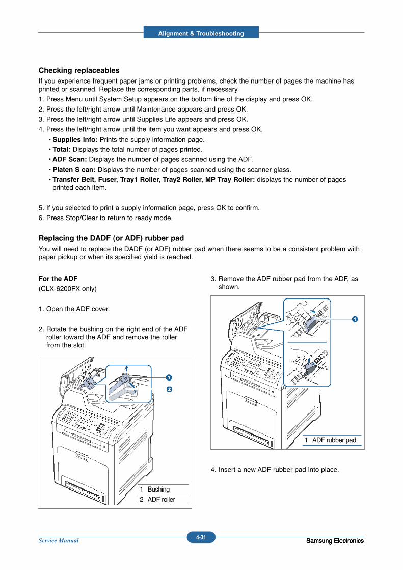
Service Manual
Alignment & Troubleshooting
4-31 Samsung ElectronicsSamsung ElectronicsSamsung ElectronicsSamsung Electronics
Checking replaceables
If you experience frequent paper jams or printing problems, check the number of pages the machine hasprinted or scanned. Replace the corresponding parts, if necessary.
1. Press Menu until System Setup appears on the bottom line of the display and press OK.
2. Press the left/right arrow until Maintenance appears and press OK.
3. Press the left/right arrow until Supplies Life appears and press OK.
4. Press the left/right arrow until the item you want appears and press OK.
• Supplies Info: Prints the supply information page.
• Total: Displays the total number of pages printed.
• ADF Scan: Displays the number of pages scanned using the ADF.
• Platen S can: Displays the number of pages scanned using the scanner glass.
• Transfer Belt, Fuser, Tray1 Roller, Tray2 Roller, MP Tray Roller: displays the number of pages printed each item.
5. If you selected to print a supply information page, press OK to confirm.
6. Press Stop/Clear to return to ready mode.
Replacing the DADF (or ADF) rubber pad
You will need to replace the DADF (or ADF) rubber pad when there seems to be a consistent problem withpaper pickup or when its specified yield is reached.
For the ADF
(CLX-6200FX only)
1. Open the ADF cover.
2. Rotate the bushing on the right end of the ADFroller toward the ADF and remove the rollerfrom the slot.
3. Remove the ADF rubber pad from the ADF, asshown.
4. Insert a new ADF rubber pad into place.
1 Bushing
2 ADF roller
1 ADF rubber pad
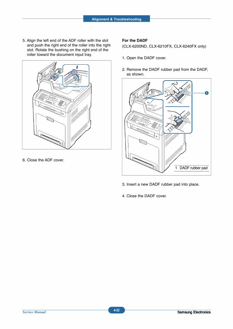
Service Manual
Alignment & Troubleshooting
4-32 Samsung ElectronicsSamsung ElectronicsSamsung ElectronicsSamsung Electronics
5. Align the left end of the ADF roller with the slotand push the right end of the roller into the rightslot. Rotate the bushing on the right end of theroller toward the document input tray.
6. Close the ADF cover.
For the DADF
(CLX-6200ND, CLX-6210FX, CLX-6240FX only)
1. Open the DADF cover.
2. Remove the DADF rubber pad from the DADF,as shown.
3. Insert a new DADF rubber pad into place.
4. Close the DADF cover.
1 DADF rubber pad
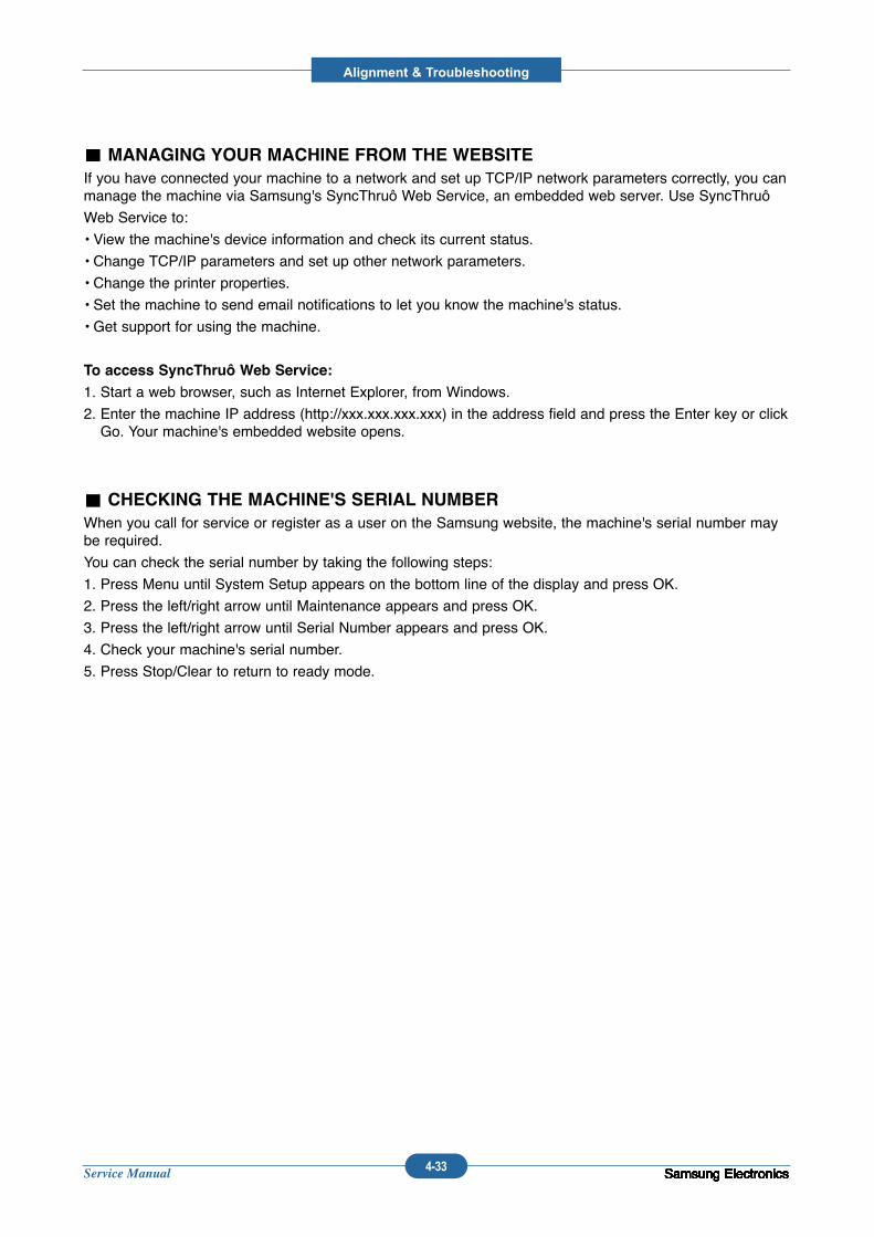
Service Manual
Alignment & Troubleshooting
4-33 Samsung ElectronicsSamsung ElectronicsSamsung ElectronicsSamsung ElectronicsSamsung ElectronicsSamsung ElectronicsSamsung ElectronicsSamsung ElectronicsSamsung ElectronicsSamsung ElectronicsSamsung Electronics
MANAGING YOUR MACHINE FROM THE WEBSITE
If you have connected your machine to a network and set up TCP/IP network parameters correctly, you canmanage the machine via Samsung's SyncThruô Web Service, an embedded web server. Use SyncThruô
Web Service to:
• View the machine's device information and check its current status.
• Change TCP/IP parameters and set up other network parameters.
• Change the printer properties.
• Set the machine to send email notifications to let you know the machine's status.
• Get support for using the machine.
To access SyncThruô Web Service:
1. Start a web browser, such as Internet Explorer, from Windows.
2. Enter the machine IP address (http://xxx.xxx.xxx.xxx) in the address field and press the Enter key or clickGo. Your machine's embedded website opens.
CHECKING THE MACHINE'S SERIAL NUMBER
When you call for service or register as a user on the Samsung website, the machine's serial number maybe required.
You can check the serial number by taking the following steps:
1. Press Menu until System Setup appears on the bottom line of the display and press OK.
2. Press the left/right arrow until Maintenance appears and press OK.
3. Press the left/right arrow until Serial Number appears and press OK.
4. Check your machine's serial number.
5. Press Stop/Clear to return to ready mode.
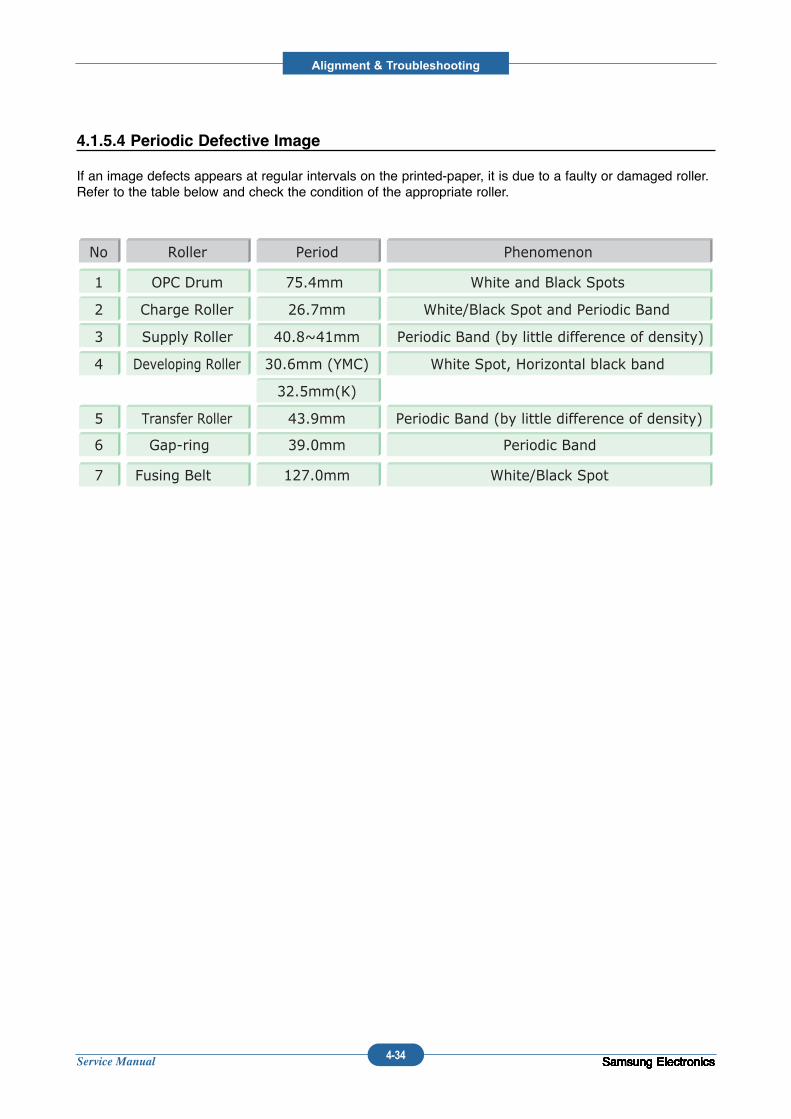
Service Manual
Alignment & Troubleshooting
4-34 Samsung ElectronicsSamsung ElectronicsSamsung ElectronicsSamsung ElectronicsSamsung ElectronicsSamsung ElectronicsSamsung ElectronicsSamsung ElectronicsSamsung ElectronicsSamsung ElectronicsSamsung Electronics
4.1.5.4 Periodic Defective Image
If an image defects appears at regular intervals on the printed-paper, it is due to a faulty or damaged roller.Refer to the table below and check the condition of the appropriate roller.
No Roller Period Phenomenon
1 OPC Drum 75.4mm White and Black Spots
2 Charge Roller 26.7mm White/Black Spot and Periodic Band
3 Supply Roller 40.8~41mm Periodic Band (by little difference of density)
4 Developing Roller 30.6mm (YMC) White Spot, Horizontal black band
32.5mm(K)
5 Transfer Roller 43.9mm Periodic Band (by little difference of density)
6 39.0mm Periodic BandGap-ring
7 127.0mm White/Black SpotFusing Belt
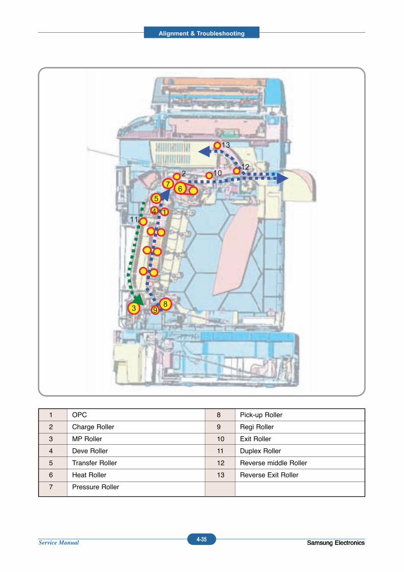
Service Manual
Alignment & Troubleshooting
4-35 Samsung ElectronicsSamsung ElectronicsSamsung ElectronicsSamsung Electronics
93
1411
5
72
6
10
8
12
13
93
1411
5
72
6
10
8
12
13
1 OPC
2 Charge Roller
3 MP Roller
4 Deve Roller
5 Transfer Roller
6 Heat Roller
7 Pressure Roller
8 Pick-up Roller
9 Regi Roller
10 Exit Roller
11 Duplex Roller
12 Reverse middle Roller
13 Reverse Exit Roller
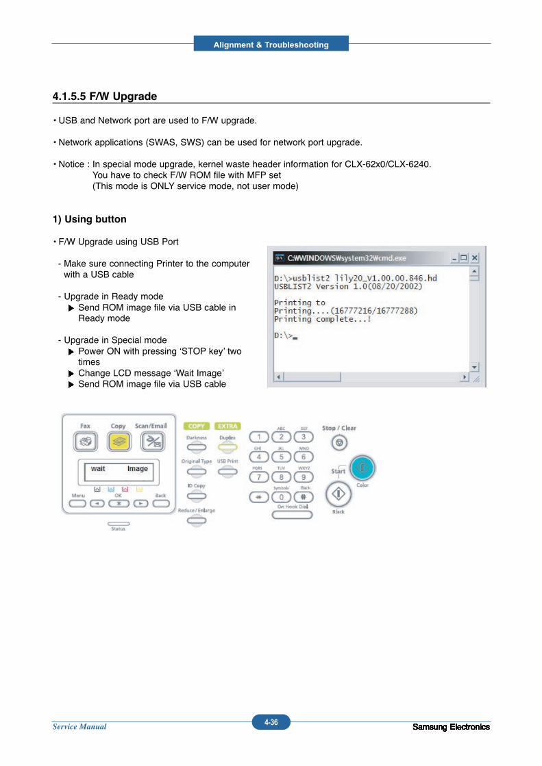
Service Manual
Alignment & Troubleshooting
4-36 Samsung ElectronicsSamsung ElectronicsSamsung ElectronicsSamsung ElectronicsSamsung ElectronicsSamsung ElectronicsSamsung ElectronicsSamsung ElectronicsSamsung ElectronicsSamsung ElectronicsSamsung ElectronicsSamsung Electronics
4.1.5.5 F/W Upgrade
• USB and Network port are used to F/W upgrade.
• Network applications (SWAS, SWS) can be used for network port upgrade.
• Notice : In special mode upgrade, kernel waste header information for CLX-62x0/CLX-6240. You have to check F/W ROM file with MFP set (This mode is ONLY service mode, not user mode)
1) Using button
• F/W Upgrade using USB Port
- Make sure connecting Printer to the computerwith a USB cable
- Upgrade in Ready modeSend ROM image file via USB cable inReady mode
- Upgrade in Special modePower ON with pressing ‘STOP key’ twotimesChange LCD message ‘Wait Image’Send ROM image file via USB cable
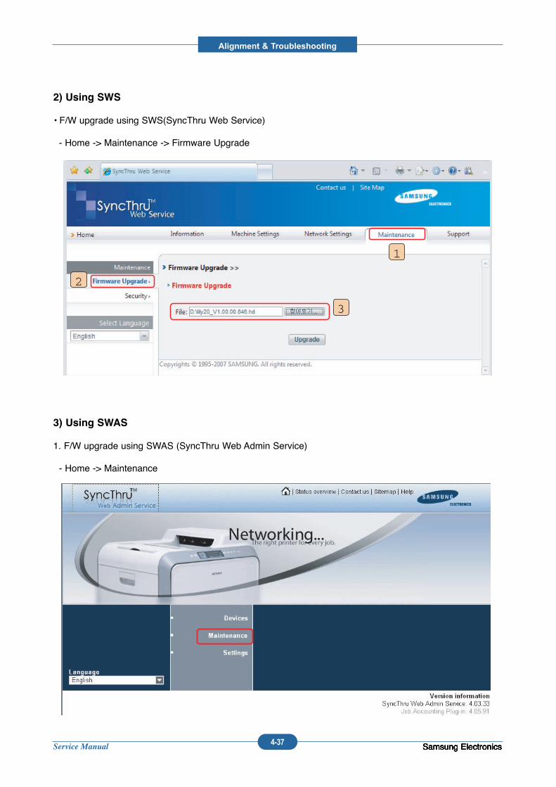
Service Manual
Alignment & Troubleshooting
4-37 Samsung ElectronicsSamsung ElectronicsSamsung ElectronicsSamsung Electronics
2) Using SWS
• F/W upgrade using SWS(SyncThru Web Service)
- Home -> Maintenance -> Firmware Upgrade
1
2
3
3) Using SWAS
1. F/W upgrade using SWAS (SyncThru Web Admin Service)
- Home -> Maintenance
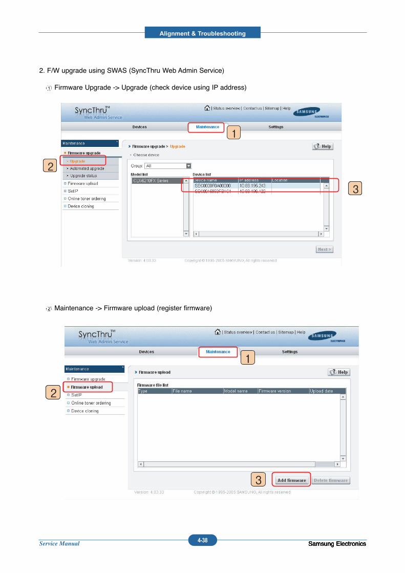
Service Manual
Alignment & Troubleshooting
4-38 Samsung ElectronicsSamsung ElectronicsSamsung ElectronicsSamsung Electronics
2. F/W upgrade using SWAS (SyncThru Web Admin Service)
Firmware Upgrade -> Upgrade (check device using IP address)
Maintenance -> Firmware upload (register firmware)
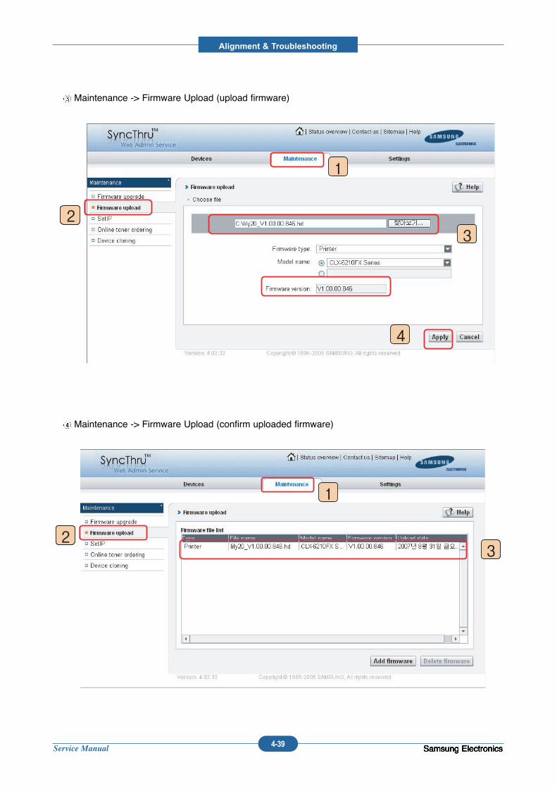
Service Manual
Alignment & Troubleshooting
4-39 Samsung ElectronicsSamsung ElectronicsSamsung ElectronicsSamsung Electronics
Maintenance -> Firmware Upload (upload firmware)
Maintenance -> Firmware Upload (confirm uploaded firmware)
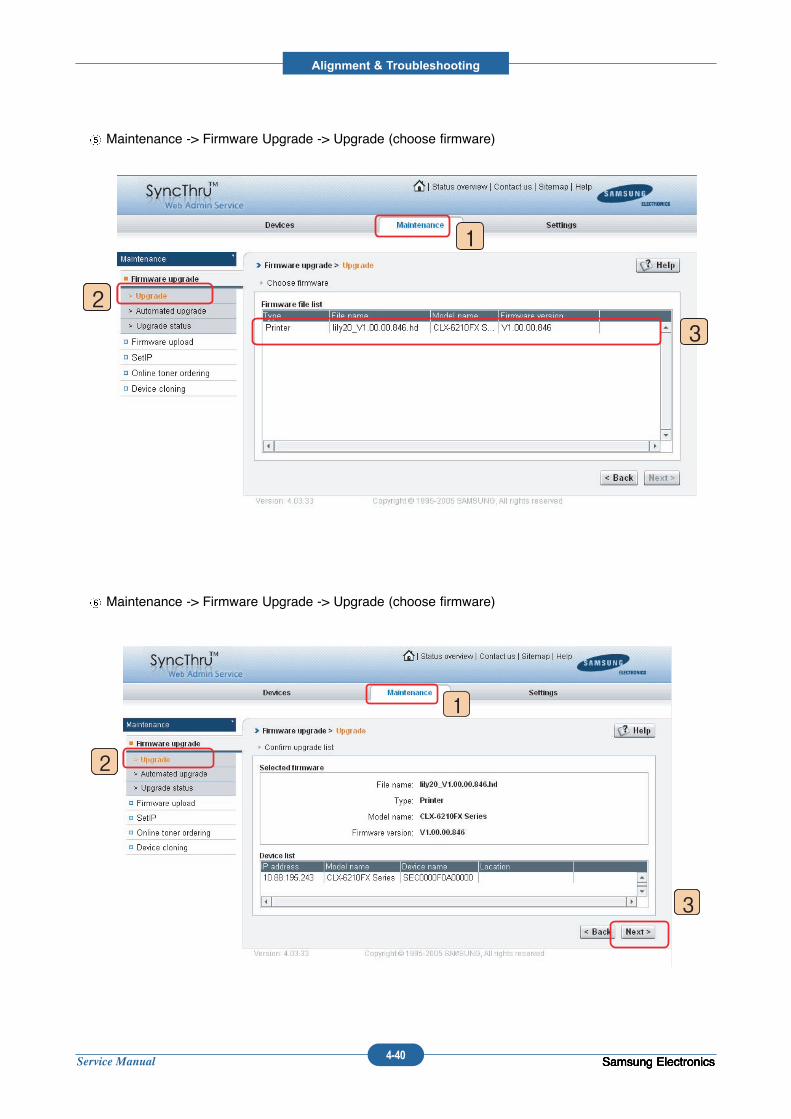
Service Manual
Alignment & Troubleshooting
4-40 Samsung ElectronicsSamsung ElectronicsSamsung ElectronicsSamsung Electronics
Maintenance -> Firmware Upgrade -> Upgrade (choose firmware)
Maintenance -> Firmware Upgrade -> Upgrade (choose firmware)
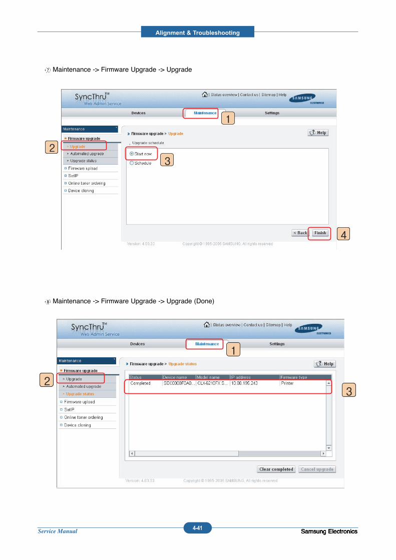
Service Manual
Alignment & Troubleshooting
4-41 Samsung ElectronicsSamsung ElectronicsSamsung ElectronicsSamsung Electronics
Maintenance -> Firmware Upgrade -> Upgrade
Maintenance -> Firmware Upgrade -> Upgrade (Done)
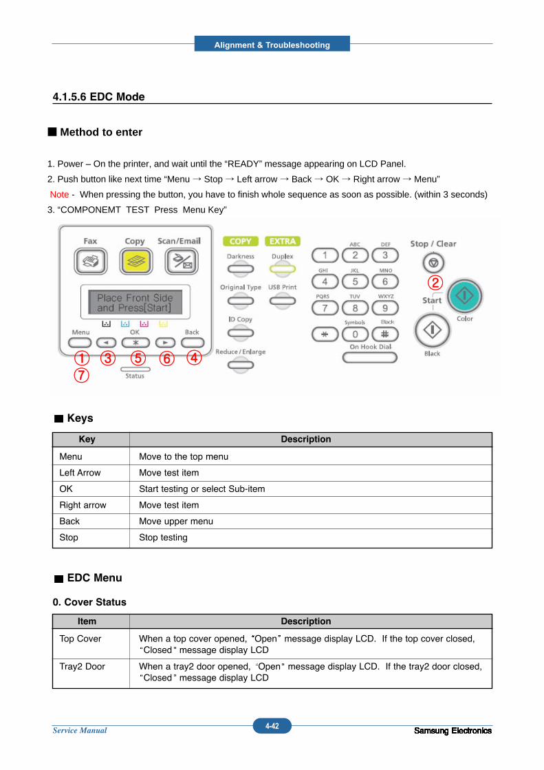
Service Manual
Alignment & Troubleshooting
4-42 Samsung ElectronicsSamsung ElectronicsSamsung ElectronicsSamsung ElectronicsSamsung Electronics
Menu Move to the top menu
Left Arrow Move test item
OK Start testing or select Sub-item
Right arrow Move test item
Back Move upper menu
Stop Stop testing
Key Description
Samsung ElectronicsSamsung ElectronicsSamsung ElectronicsSamsung ElectronicsSamsung ElectronicsSamsung ElectronicsSamsung ElectronicsSamsung Electronics
4.1.5.6 EDC Mode
Keys
Top Cover When a top cover opened, Open message display LCD. If the top cover closed, Closed message display LCD
Tray2 Door When a tray2 door opened, Open message display LCD. If the tray2 door closed,Closed message display LCD
Item Description
EDC Menu
0. Cover Status
①
②
③ ④⑤ ⑥⑦
■ Method to enter
1. Power – On the printer, and wait until the “READY” message appearing on LCD Panel.
2. Push button like next time “Menu → Stop → Left arrow → Back → OK → Right arrow → Menu”
Note - When pressing the button, you have to finish whole sequence as soon as possible. (within 3 seconds)
3. “COMPONEMT TEST Press Menu Key”
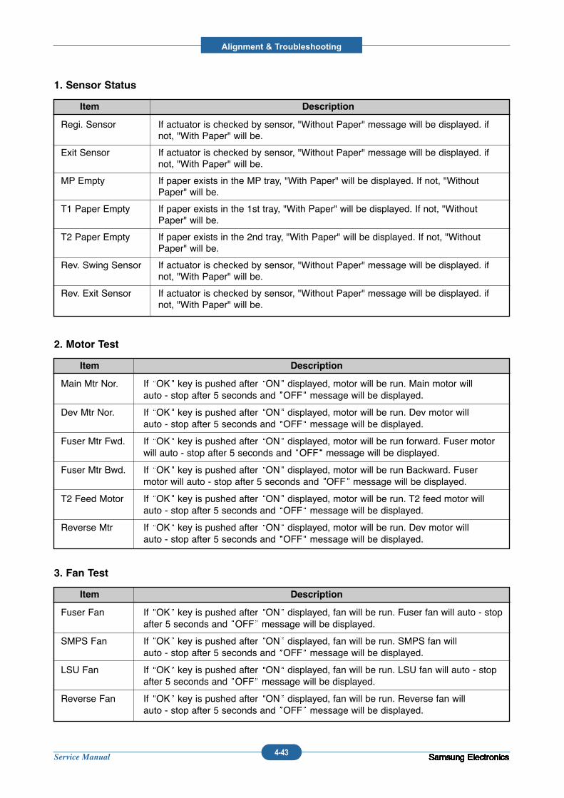
Service Manual
Alignment & Troubleshooting
4-43 Samsung ElectronicsSamsung ElectronicsSamsung ElectronicsSamsung ElectronicsSamsung ElectronicsSamsung ElectronicsSamsung ElectronicsSamsung ElectronicsSamsung ElectronicsSamsung ElectronicsSamsung ElectronicsSamsung ElectronicsSamsung Electronics
Main Mtr Nor. If OK key is pushed after ON displayed, motor will be run. Main motor will auto - stop after 5 seconds and OFF message will be displayed.
Dev Mtr Nor. If OK key is pushed after ON displayed, motor will be run. Dev motor will auto - stop after 5 seconds and OFF message will be displayed.
Fuser Mtr Fwd. If OK key is pushed after ON displayed, motor will be run forward. Fuser motorwill auto - stop after 5 seconds and OFF message will be displayed.
Fuser Mtr Bwd. If OK key is pushed after ON displayed, motor will be run Backward. Fusermotor will auto - stop after 5 seconds and OFF message will be displayed.
T2 Feed Motor If OK key is pushed after ON displayed, motor will be run. T2 feed motor willauto - stop after 5 seconds and OFF message will be displayed.
Reverse Mtr If OK key is pushed after ON displayed, motor will be run. Dev motor will auto - stop after 5 seconds and OFF message will be displayed.
Item Description
2. Motor Test
Fuser Fan If OK key is pushed after ON displayed, fan will be run. Fuser fan will auto - stopafter 5 seconds and OFF message will be displayed.
SMPS Fan If OK key is pushed after ON displayed, fan will be run. SMPS fan will auto - stop after 5 seconds and OFF message will be displayed.
LSU Fan If OK key is pushed after ON displayed, fan will be run. LSU fan will auto - stopafter 5 seconds and OFF message will be displayed.
Reverse Fan If OK key is pushed after ON displayed, fan will be run. Reverse fan will auto - stop after 5 seconds and OFF message will be displayed.
Item Description
3. Fan Test
Regi. Sensor If actuator is checked by sensor, "Without Paper" message will be displayed. ifnot, "With Paper" will be.
Exit Sensor If actuator is checked by sensor, "Without Paper" message will be displayed. ifnot, "With Paper" will be.
MP Empty If paper exists in the MP tray, "With Paper" will be displayed. If not, "WithoutPaper" will be.
T1 Paper Empty If paper exists in the 1st tray, "With Paper" will be displayed. If not, "WithoutPaper" will be.
T2 Paper Empty If paper exists in the 2nd tray, "With Paper" will be displayed. If not, "WithoutPaper" will be.
Rev. Swing Sensor If actuator is checked by sensor, "Without Paper" message will be displayed. ifnot, "With Paper" will be.
Rev. Exit Sensor If actuator is checked by sensor, "Without Paper" message will be displayed. ifnot, "With Paper" will be.
Item Description
1. Sensor Status
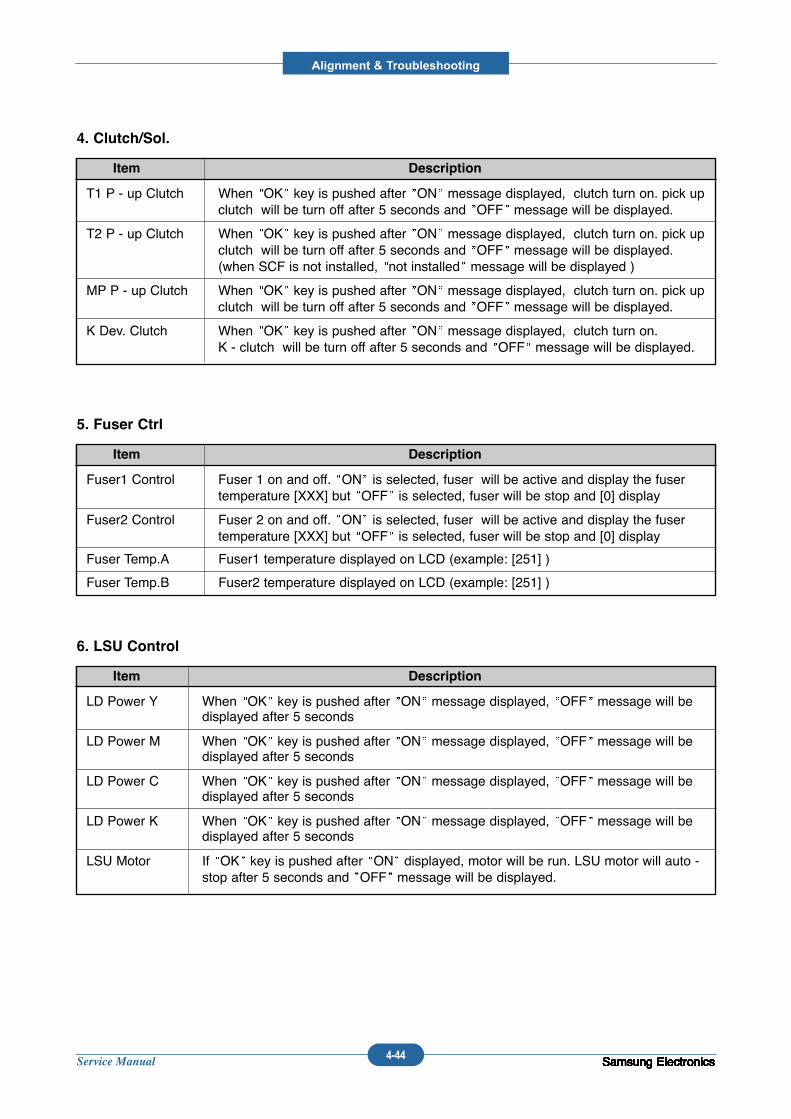
Service Manual
Alignment & Troubleshooting
4-44 Samsung ElectronicsSamsung ElectronicsSamsung ElectronicsSamsung ElectronicsSamsung ElectronicsSamsung ElectronicsSamsung ElectronicsSamsung ElectronicsSamsung ElectronicsSamsung ElectronicsSamsung ElectronicsSamsung ElectronicsSamsung Electronics
T1 P - up Clutch When OK key is pushed after ON message displayed, clutch turn on. pick upclutch will be turn off after 5 seconds and OFF message will be displayed.
T2 P - up Clutch When OK key is pushed after ON message displayed, clutch turn on. pick upclutch will be turn off after 5 seconds and OFF message will be displayed.(when SCF is not installed, not installed message will be displayed )
MP P - up Clutch When OK key is pushed after ON message displayed, clutch turn on. pick upclutch will be turn off after 5 seconds and OFF message will be displayed.
K Dev. Clutch When OK key is pushed after ON message displayed, clutch turn on. K - clutch will be turn off after 5 seconds and OFF message will be displayed.
Item Description
4. Clutch/Sol.
Fuser1 Control Fuser 1 on and off. ON is selected, fuser will be active and display the fusertemperature [XXX] but OFF is selected, fuser will be stop and [0] display
Fuser2 Control Fuser 2 on and off. ON is selected, fuser will be active and display the fusertemperature [XXX] but OFF is selected, fuser will be stop and [0] display
Fuser Temp.A Fuser1 temperature displayed on LCD (example: [251] )
Fuser Temp.B Fuser2 temperature displayed on LCD (example: [251] )
Item Description
5. Fuser Ctrl
LD Power Y When OK key is pushed after ON message displayed, OFF message will bedisplayed after 5 seconds
LD Power M When OK key is pushed after ON message displayed, OFF message will bedisplayed after 5 seconds
LD Power C When OK key is pushed after ON message displayed, OFF message will bedisplayed after 5 seconds
LD Power K When OK key is pushed after ON message displayed, OFF message will bedisplayed after 5 seconds
LSU Motor If OK key is pushed after ON displayed, motor will be run. LSU motor will auto -stop after 5 seconds and OFF message will be displayed.
Item Description
6. LSU Control
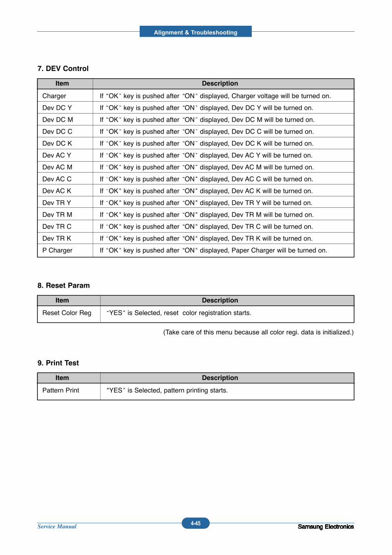
Service Manual
Alignment & Troubleshooting
4-45 Samsung ElectronicsSamsung ElectronicsSamsung ElectronicsSamsung ElectronicsSamsung ElectronicsSamsung ElectronicsSamsung ElectronicsSamsung ElectronicsSamsung ElectronicsSamsung ElectronicsSamsung ElectronicsSamsung ElectronicsSamsung Electronics
Reset Color Reg YES is Selected, reset color registration starts.
(Take care of this menu because all color regi. data is initialized.)
Item Description
8. Reset Param
Pattern Print YES is Selected, pattern printing starts.
Item Description
9. Print Test
Charger If OK key is pushed after ON displayed, Charger voltage will be turned on.
Dev DC Y If OK key is pushed after ON displayed, Dev DC Y will be turned on.
Dev DC M If OK key is pushed after ON displayed, Dev DC M will be turned on.
Dev DC C If OK key is pushed after ON displayed, Dev DC C will be turned on.
Dev DC K If OK key is pushed after ON displayed, Dev DC K will be turned on.
Dev AC Y If OK key is pushed after ON displayed, Dev AC Y will be turned on.
Dev AC M If OK key is pushed after ON displayed, Dev AC M will be turned on.
Dev AC C If OK key is pushed after ON displayed, Dev AC C will be turned on.
Dev AC K If OK key is pushed after ON displayed, Dev AC K will be turned on.
Dev TR Y If OK key is pushed after ON displayed, Dev TR Y will be turned on.
Dev TR M If OK key is pushed after ON displayed, Dev TR M will be turned on.
Dev TR C If OK key is pushed after ON displayed, Dev TR C will be turned on.
Dev TR K If OK key is pushed after ON displayed, Dev TR K will be turned on.
P Charger If OK key is pushed after ON displayed, Paper Charger will be turned on.
Item Description
7. DEV Control
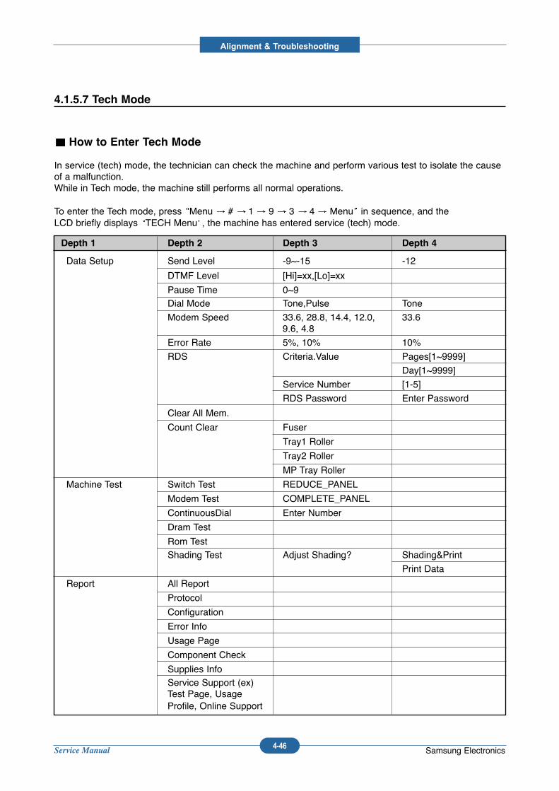
Service Manual
Alignment & Troubleshooting
4-46 Samsung Electronics
4.1.5.7 Tech Mode
How to Enter Tech Mode
In service (tech) mode, the technician can check the machine and perform various test to isolate the causeof a malfunction.While in Tech mode, the machine still performs all normal operations.
To enter the Tech mode, press Menu # 1 9 3 4 Menu in sequence, and theLCD briefly displays TECH Menu , the machine has entered service (tech) mode.
Data Setup Send Level -9~-15 -12
DTMF Level [Hi]=xx,[Lo]=xx
Pause Time 0~9Dial Mode Tone,Pulse Tone
Modem Speed 33.6, 28.8, 14.4, 12.0, 33.69.6, 4.8
Error Rate 5%, 10% 10%
RDS Criteria.Value Pages[1~9999]
Day[1~9999]
Service Number [1-5]
RDS Password Enter Password
Clear All Mem.
Count Clear Fuser
Tray1 Roller
Tray2 Roller
MP Tray Roller
Machine Test Switch Test REDUCE_PANEL
Modem Test COMPLETE_PANEL
ContinuousDial Enter Number
Dram Test
Rom TestShading Test Adjust Shading? Shading&Print
Print Data
Report All Report
Protocol
Configuration
Error Info
Usage Page
Component Check
Supplies InfoService Support (ex) Test Page, Usage Profile, Online Support
Depth 1 Depth 2 Depth 3 Depth 4
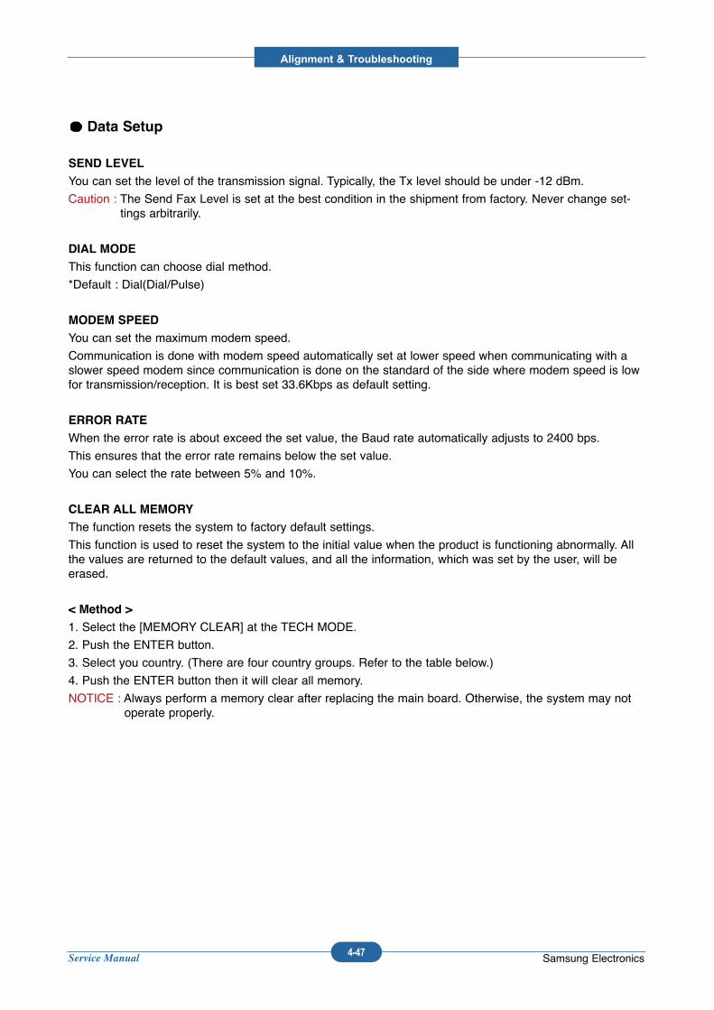
Service Manual
Alignment & Troubleshooting
4-47 Samsung Electronics
Data Setup
SEND LEVEL
You can set the level of the transmission signal. Typically, the Tx level should be under -12 dBm.
Caution : The Send Fax Level is set at the best condition in the shipment from factory. Never change set-tings arbitrarily.
DIAL MODE
This function can choose dial method.
*Default : Dial(Dial/Pulse)
MODEM SPEED
You can set the maximum modem speed.
Communication is done with modem speed automatically set at lower speed when communicating with aslower speed modem since communication is done on the standard of the side where modem speed is lowfor transmission/reception. It is best set 33.6Kbps as default setting.
ERROR RATE
When the error rate is about exceed the set value, the Baud rate automatically adjusts to 2400 bps.
This ensures that the error rate remains below the set value.
You can select the rate between 5% and 10%.
CLEAR ALL MEMORY
The function resets the system to factory default settings.
This function is used to reset the system to the initial value when the product is functioning abnormally. Allthe values are returned to the default values, and all the information, which was set by the user, will beerased.
< Method >
1. Select the [MEMORY CLEAR] at the TECH MODE.
2. Push the ENTER button.
3. Select you country. (There are four country groups. Refer to the table below.)
4. Push the ENTER button then it will clear all memory.
NOTICE : Always perform a memory clear after replacing the main board. Otherwise, the system may notoperate properly.
Service Manual
Alignment & Troubleshooting
4-48 Samsung Electronics
Machine Test
SWITCH TEST
Use this feature to test all keys on the operation control panel. The result is displayed on the LCD
window each time you press a key.
MODEM TEST
Use this feature to hear various transmission signals to the telephone line from the modem and to
check the modem. If no transmission signal sound is heard, it means the modem part of the main
board malfunctioned.
DRAM TEST
Use this feature to test the machine's DRAM. The result appears in the LCD display.
If all memory is working normally, the LCD shows << O K >>
ROM TEST
Use this feature to test the machine'S ROM. The result and the software version appear in the LCD
display.
PATTERN TEST
Using this pattern printout, you can check if the printer mechanism is functioning properly.
It is needed in the production progress. Service person doesn't need to use it.
SHADING TEST
The function is to get the optimum scan quality by the specific character of the CCD(Charge
Coupled Device). If the copy image quality is poor, perform this function to check the condition
CCD unit.
< Method >
1. Select the [ADJUST SHADING] at the TECH MODE.
2. Push the SET UP button then an image will be scanned.
3. After the scan, CCD SHADING PROFILE will be print out.
4. If the printed image is different to the image, the CCD is defect.
NOTICE : When you test CCD, make sure that the cover is closed.
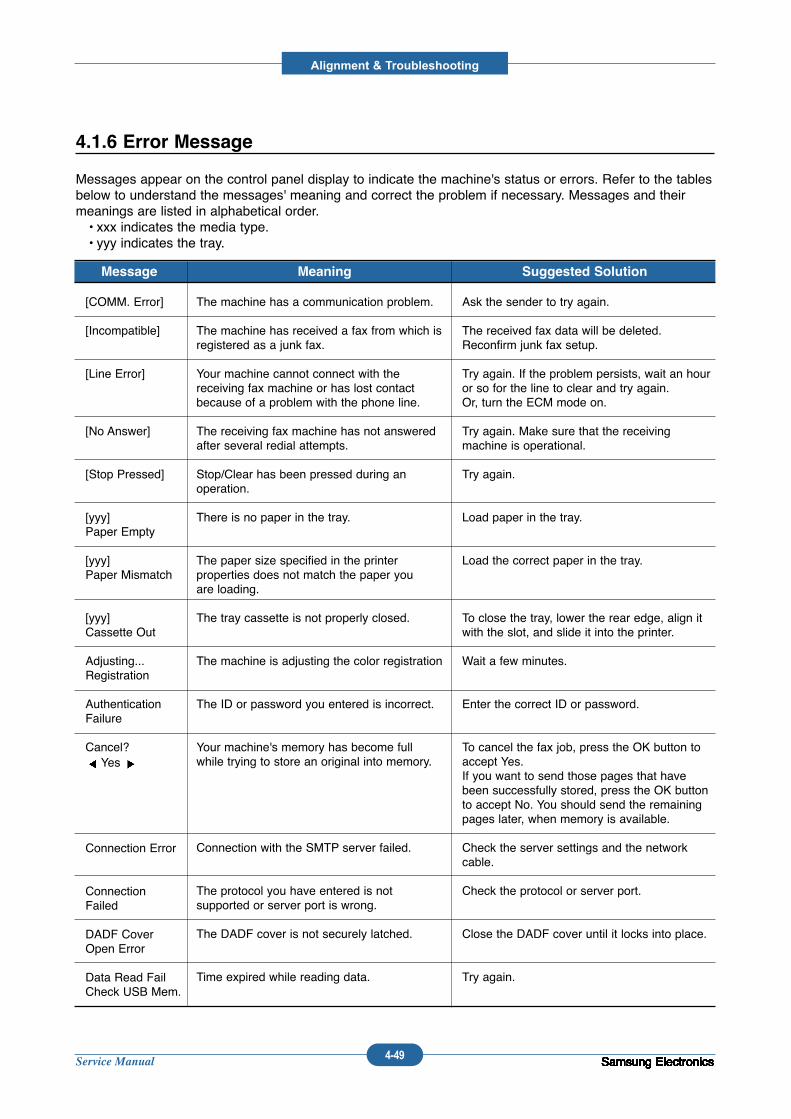
Service Manual
Alignment & Troubleshooting
4-49 Samsung ElectronicsSamsung ElectronicsSamsung ElectronicsSamsung ElectronicsSamsung ElectronicsSamsung ElectronicsSamsung ElectronicsSamsung ElectronicsSamsung ElectronicsSamsung ElectronicsSamsung ElectronicsSamsung ElectronicsSamsung ElectronicsSamsung Electronics
4.1.6 Error Message
Messages appear on the control panel display to indicate the machine's status or errors. Refer to the tablesbelow to understand the messages' meaning and correct the problem if necessary. Messages and theirmeanings are listed in alphabetical order.• xxx indicates the media type.• yyy indicates the tray.
[COMM. Error]
[Incompatible]
[Line Error]
[No Answer]
[Stop Pressed]
[yyy] Paper Empty
[yyy] Paper Mismatch
[yyy] Cassette Out
Adjusting...Registration
AuthenticationFailure
Cancel?Yes
Connection Error
ConnectionFailed
DADF CoverOpen Error
Data Read FailCheck USB Mem.
The machine has a communication problem.
The machine has received a fax from which isregistered as a junk fax.
Your machine cannot connect with the receiving fax machine or has lost contactbecause of a problem with the phone line.
The receiving fax machine has not answeredafter several redial attempts.
Stop/Clear has been pressed during anoperation.
There is no paper in the tray.
The paper size specified in the printer properties does not match the paper youare loading.
The tray cassette is not properly closed.
The machine is adjusting the color registration
The ID or password you entered is incorrect.
Your machine's memory has become fullwhile trying to store an original into memory.
Connection with the SMTP server failed.
The protocol you have entered is not supported or server port is wrong.
The DADF cover is not securely latched.
Time expired while reading data.
Ask the sender to try again.
The received fax data will be deleted.Reconfirm junk fax setup.
Try again. If the problem persists, wait an houror so for the line to clear and try again.Or, turn the ECM mode on.
Try again. Make sure that the receivingmachine is operational.
Try again.
Load paper in the tray.
Load the correct paper in the tray.
To close the tray, lower the rear edge, align itwith the slot, and slide it into the printer.
Wait a few minutes.
Enter the correct ID or password.
To cancel the fax job, press the OK button toaccept Yes.If you want to send those pages that havebeen successfully stored, press the OK buttonto accept No. You should send the remainingpages later, when memory is available.
Check the server settings and the networkcable.
Check the protocol or server port.
Close the DADF cover until it locks into place.
Try again.
Message Meaning Suggested Solution
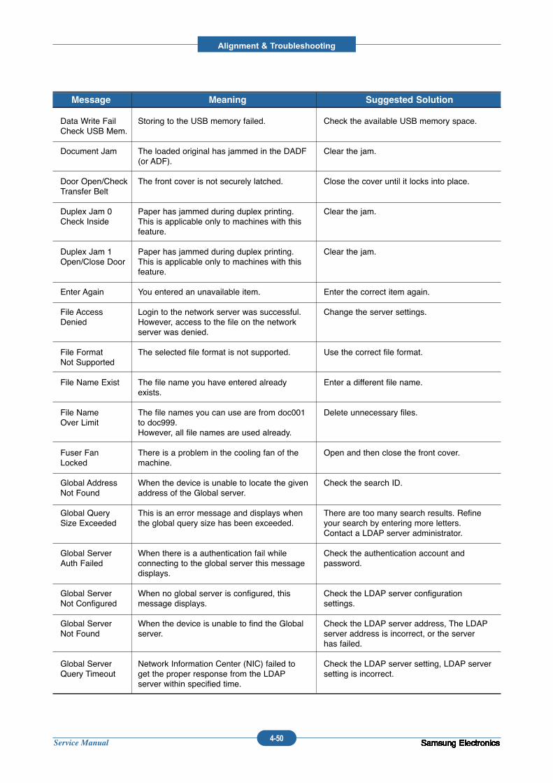
Service Manual
Alignment & Troubleshooting
4-50 Samsung ElectronicsSamsung ElectronicsSamsung ElectronicsSamsung ElectronicsSamsung ElectronicsSamsung ElectronicsSamsung ElectronicsSamsung ElectronicsSamsung ElectronicsSamsung ElectronicsSamsung ElectronicsSamsung ElectronicsSamsung ElectronicsSamsung Electronics
Data Write FailCheck USB Mem.
Document Jam
Door Open/CheckTransfer Belt
Duplex Jam 0Check Inside
Duplex Jam 1Open/Close Door
Enter Again
File AccessDenied
File FormatNot Supported
File Name Exist
File NameOver Limit
Fuser FanLocked
Global AddressNot Found
Global QuerySize Exceeded
Global ServerAuth Failed
Global ServerNot Configured
Global ServerNot Found
Global ServerQuery Timeout
Storing to the USB memory failed.
The loaded original has jammed in the DADF(or ADF).
The front cover is not securely latched.
Paper has jammed during duplex printing.This is applicable only to machines with thisfeature.
Paper has jammed during duplex printing.This is applicable only to machines with thisfeature.
You entered an unavailable item.
Login to the network server was successful.However, access to the file on the networkserver was denied.
The selected file format is not supported.
The file name you have entered alreadyexists.
The file names you can use are from doc001to doc999.However, all file names are used already.
There is a problem in the cooling fan of themachine.
When the device is unable to locate the givenaddress of the Global server.
This is an error message and displays whenthe global query size has been exceeded.
When there is a authentication fail while connecting to the global server this messagedisplays.
When no global server is configured, thismessage displays.
When the device is unable to find the Globalserver.
Network Information Center (NIC) failed toget the proper response from the LDAPserver within specified time.
Check the available USB memory space.
Clear the jam.
Close the cover until it locks into place.
Clear the jam.
Clear the jam.
Enter the correct item again.
Change the server settings.
Use the correct file format.
Enter a different file name.
Delete unnecessary files.
Open and then close the front cover.
Check the search ID.
There are too many search results. Refineyour search by entering more letters.Contact a LDAP server administrator.
Check the authentication account and password.
Check the LDAP server configuration settings.
Check the LDAP server address, The LDAPserver address is incorrect, or the serverhas failed.
Check the LDAP server setting, LDAP serversetting is incorrect.
Message Meaning Suggested Solution
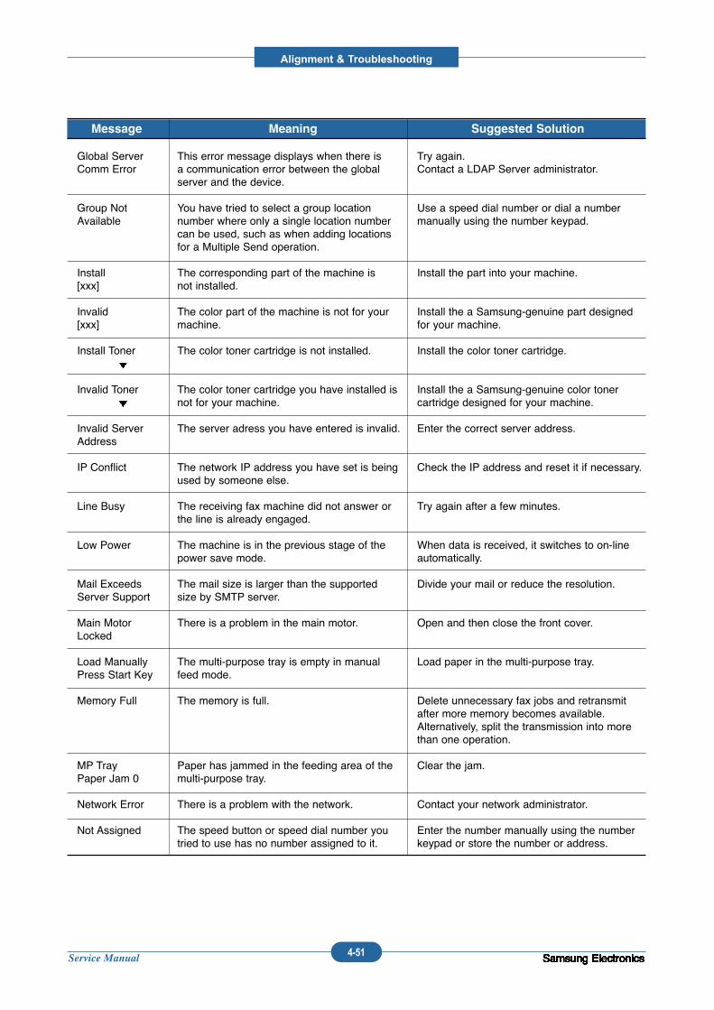
Service Manual
Alignment & Troubleshooting
4-51 Samsung ElectronicsSamsung ElectronicsSamsung ElectronicsSamsung ElectronicsSamsung ElectronicsSamsung ElectronicsSamsung ElectronicsSamsung ElectronicsSamsung ElectronicsSamsung ElectronicsSamsung ElectronicsSamsung ElectronicsSamsung ElectronicsSamsung Electronics
Global ServerComm Error
Group NotAvailable
Install[xxx]
Invalid[xxx]
Install Toner
Invalid Toner
Invalid ServerAddress
IP Conflict
Line Busy
Low Power
Mail ExceedsServer Support
Main MotorLocked
Load ManuallyPress Start Key
Memory Full
MP TrayPaper Jam 0
Network Error
Not Assigned
This error message displays when there isa communication error between the globalserver and the device.
You have tried to select a group locationnumber where only a single location numbercan be used, such as when adding locationsfor a Multiple Send operation.
The corresponding part of the machine isnot installed.
The color part of the machine is not for yourmachine.
The color toner cartridge is not installed.
The color toner cartridge you have installed isnot for your machine.
The server adress you have entered is invalid.
The network IP address you have set is beingused by someone else.
The receiving fax machine did not answer orthe line is already engaged.
The machine is in the previous stage of thepower save mode.
The mail size is larger than the supportedsize by SMTP server.
There is a problem in the main motor.
The multi-purpose tray is empty in manualfeed mode.
The memory is full.
Paper has jammed in the feeding area of themulti-purpose tray.
There is a problem with the network.
The speed button or speed dial number youtried to use has no number assigned to it.
Try again.Contact a LDAP Server administrator.
Use a speed dial number or dial a numbermanually using the number keypad.
Install the part into your machine.
Install the a Samsung-genuine part designedfor your machine.
Install the color toner cartridge.
Install the a Samsung-genuine color tonercartridge designed for your machine.
Enter the correct server address.
Check the IP address and reset it if necessary.
Try again after a few minutes.
When data is received, it switches to on-lineautomatically.
Divide your mail or reduce the resolution.
Open and then close the front cover.
Load paper in the multi-purpose tray.
Delete unnecessary fax jobs and retransmitafter more memory becomes available.Alternatively, split the transmission into morethan one operation.
Clear the jam.
Contact your network administrator.
Enter the number manually using the numberkeypad or store the number or address.
Message Meaning Suggested Solution
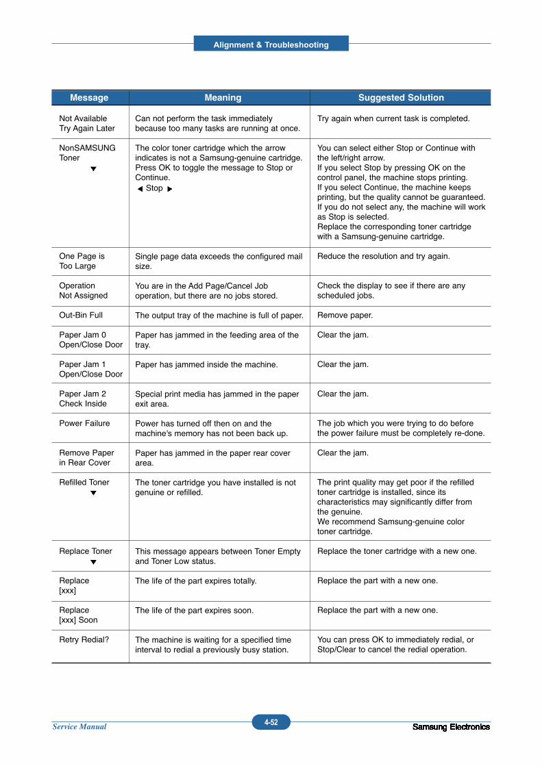
Service Manual
Alignment & Troubleshooting
4-52 Samsung ElectronicsSamsung ElectronicsSamsung ElectronicsSamsung ElectronicsSamsung ElectronicsSamsung ElectronicsSamsung ElectronicsSamsung ElectronicsSamsung ElectronicsSamsung ElectronicsSamsung ElectronicsSamsung ElectronicsSamsung ElectronicsSamsung Electronics
Not AvailableTry Again Later
NonSAMSUNGToner
One Page isToo Large
OperationNot Assigned
Out-Bin Full
Paper Jam 0Open/Close Door
Paper Jam 1Open/Close Door
Paper Jam 2Check Inside
Power Failure
Remove Paperin Rear Cover
Refilled Toner
Replace Toner
Replace[xxx]
Replace[xxx] Soon
Retry Redial?
Can not perform the task immediatelybecause too many tasks are running at once.
The color toner cartridge which the arrow indicates is not a Samsung-genuine cartridge.Press OK to toggle the message to Stop orContinue.Stop
Single page data exceeds the configured mailsize.
You are in the Add Page/Cancel Job operation, but there are no jobs stored.
The output tray of the machine is full of paper.
Paper has jammed in the feeding area of thetray.
Paper has jammed inside the machine.
Special print media has jammed in the paperexit area.
Power has turned off then on and themachine's memory has not been back up.
Paper has jammed in the paper rear coverarea.
The toner cartridge you have installed is notgenuine or refilled.
This message appears between Toner Emptyand Toner Low status.
The life of the part expires totally.
The life of the part expires soon.
The machine is waiting for a specified timeinterval to redial a previously busy station.
Try again when current task is completed.
You can select either Stop or Continue withthe left/right arrow.If you select Stop by pressing OK on the control panel, the machine stops printing.If you select Continue, the machine keepsprinting, but the quality cannot be guaranteed.If you do not select any, the machine will workas Stop is selected.Replace the corresponding toner cartridgewith a Samsung-genuine cartridge.
Reduce the resolution and try again.
Check the display to see if there are anyscheduled jobs.
Remove paper.
Clear the jam.
Clear the jam.
Clear the jam.
The job which you were trying to do beforethe power failure must be completely re-done.
Clear the jam.
The print quality may get poor if the refilledtoner cartridge is installed, since its characteristics may significantly differ fromthe genuine.We recommend Samsung-genuine colortoner cartridge.
Replace the toner cartridge with a new one.
Replace the part with a new one.
Replace the part with a new one.
You can press OK to immediately redial, orStop/Clear to cancel the redial operation.
Message Meaning Suggested Solution
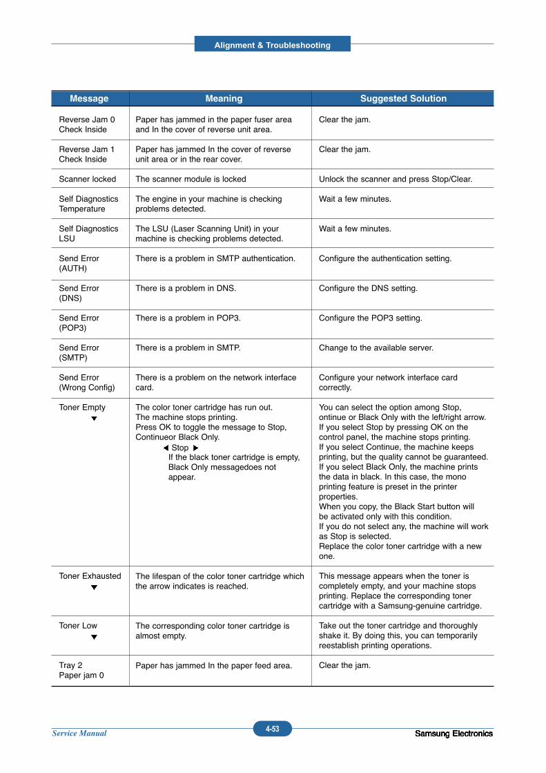
Service Manual
Alignment & Troubleshooting
4-53 Samsung ElectronicsSamsung ElectronicsSamsung ElectronicsSamsung ElectronicsSamsung Electronics
Reverse Jam 0Check Inside
Reverse Jam 1Check Inside
Scanner locked
Self DiagnosticsTemperature
Self DiagnosticsLSU
Send Error(AUTH)
Send Error (DNS)
Send Error(POP3)
Send Error(SMTP)
Send Error(Wrong Config)
Toner Empty
Toner Exhausted
Toner Low
Tray 2Paper jam 0
Paper has jammed in the paper fuser areaand In the cover of reverse unit area.
Paper has jammed In the cover of reverseunit area or in the rear cover.
The scanner module is locked
The engine in your machine is checking problems detected.
The LSU (Laser Scanning Unit) in yourmachine is checking problems detected.
There is a problem in SMTP authentication.
There is a problem in DNS.
There is a problem in POP3.
There is a problem in SMTP.
There is a problem on the network interfacecard.
The color toner cartridge has run out.The machine stops printing.Press OK to toggle the message to Stop,Continueor Black Only.
Stop If the black toner cartridge is empty,Black Only messagedoes notappear.
The lifespan of the color toner cartridge whichthe arrow indicates is reached.
The corresponding color toner cartridge isalmost empty.
Paper has jammed In the paper feed area.
Clear the jam.
Clear the jam.
Unlock the scanner and press Stop/Clear.
Wait a few minutes.
Wait a few minutes.
Configure the authentication setting.
Configure the DNS setting.
Configure the POP3 setting.
Change to the available server.
Configure your network interface card correctly.
You can select the option among Stop, ontinue or Black Only with the left/right arrow.If you select Stop by pressing OK on thecontrol panel, the machine stops printing.If you select Continue, the machine keepsprinting, but the quality cannot be guaranteed.If you select Black Only, the machine printsthe data in black. In this case, the mono printing feature is preset in the printer properties.When you copy, the Black Start button willbe activated only with this condition.If you do not select any, the machine will workas Stop is selected.Replace the color toner cartridge with a newone.
This message appears when the toner iscompletely empty, and your machine stopsprinting. Replace the corresponding tonercartridge with a Samsung-genuine cartridge.
Take out the toner cartridge and thoroughlyshake it. By doing this, you can temporarilyreestablish printing operations.
Clear the jam.
Message Meaning Suggested Solution

Service Manual
Alignment & Troubleshooting
4-54 Samsung ElectronicsSamsung ElectronicsSamsung ElectronicsSamsung ElectronicsSamsung ElectronicsSamsung ElectronicsSamsung ElectronicsSamsung ElectronicsSamsung ElectronicsSamsung Electronics
4.2 Troubleshooting
4.2.1 Procedure of Checking the Symptoms
Before attempting to repair the printer first obtain a detailed description of the problem from the customer.
Power On
- No Power- Power Module error- Main PBA error- LCD Panel error
Refer to "Solutionof Image Problem"
OP PanelON?
Ready orPower save
IndicateError Massage
Refer toError Massage<Chapter 4.1.6>
Test Print
�END
printingQuality isNomal?
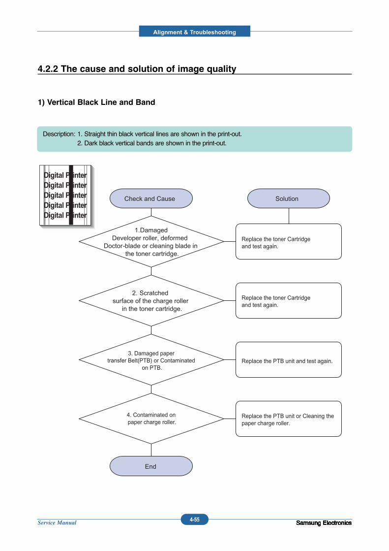
Service Manual
Alignment & Troubleshooting
4-55 Samsung ElectronicsSamsung ElectronicsSamsung ElectronicsSamsung ElectronicsSamsung ElectronicsSamsung ElectronicsSamsung ElectronicsSamsung ElectronicsSamsung ElectronicsSamsung Electronics
4.2.2 The cause and solution of image quality
1) Vertical Black Line and Band
Description: 1. Straight thin black vertical lines are shown in the print-out.2. Dark black vertical bands are shown in the print-out.
3. Damaged paper transfer Belt(PTB) or Contaminated
on PTB.
4. Contaminated on paper charge roller.
Replace the toner Cartridge and test again.
Replace the toner Cartridge and test again.
Replace the PTB unit and test again.
Replace the PTB unit or Cleaning thepaper charge roller.
Digital PrinterDigital PrinterDigital PrinterDigital PrinterDigital Printer
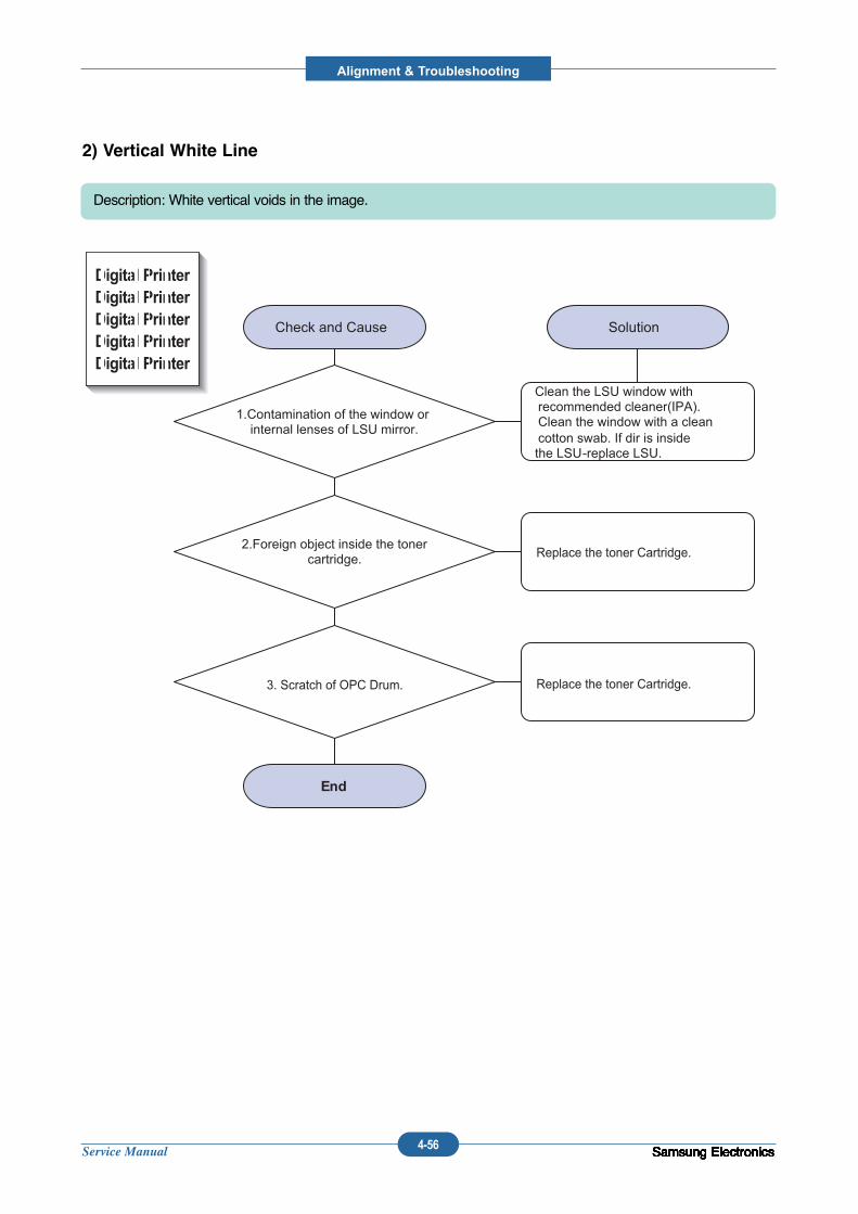
Service Manual
Alignment & Troubleshooting
4-56 Samsung ElectronicsSamsung ElectronicsSamsung ElectronicsSamsung ElectronicsSamsung ElectronicsSamsung ElectronicsSamsung ElectronicsSamsung ElectronicsSamsung ElectronicsSamsung Electronics
2) Vertical White Line
Description: White vertical voids in the image.
Replace the toner Cartridge.
Replace the toner Cartridge.3. Scratch of OPC Drum.
Digital PrinterDigital PrinterDigital PrinterDigital PrinterDigital Printer
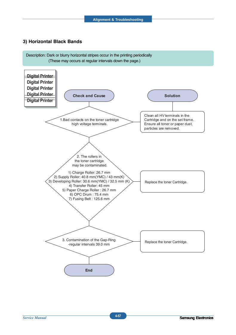
Service Manual
Alignment & Troubleshooting
4-57 Samsung ElectronicsSamsung ElectronicsSamsung ElectronicsSamsung ElectronicsSamsung ElectronicsSamsung ElectronicsSamsung ElectronicsSamsung ElectronicsSamsung ElectronicsSamsung Electronics
3) Horizontal Black Bands
Description: Dark or blurry horizontal stripes occur in the printing periodically(These may occurs at regular intervals down the page.)
1) Charge Roller: 26.7 mm2) Supply Roller: 40.8 mm(YMC) / 43 mm(K)
3) Developing Roller: 30.6 mm(YMC) / 32.5 mm (K)4) Transfer Roller: 45 mm
5) Paper Charge Roller : 26.7 mm6) OPC Drum : 75.4 mm7) Fusing Belt : 125.6 mm
Replace the toner Cartridge.
Replace the toner Cartridge.
2. The rollers in the toner cartridge
may be contaminated.
3. Contamination of the Gap-Ring-regular intervals 39.0 mm
Digital PrinterDigital PrinterDigital PrinterDigital PrinterDigital Printer
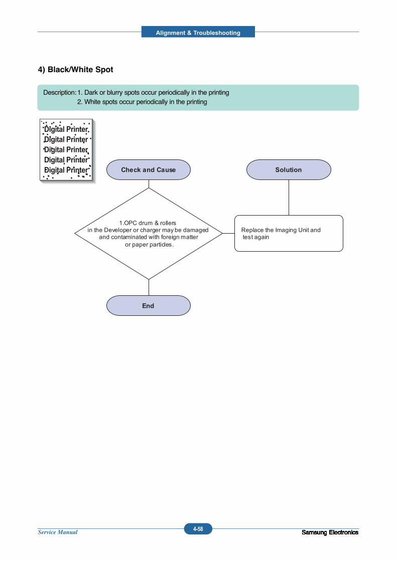
Service Manual
Alignment & Troubleshooting
4-58 Samsung ElectronicsSamsung ElectronicsSamsung ElectronicsSamsung ElectronicsSamsung ElectronicsSamsung ElectronicsSamsung ElectronicsSamsung ElectronicsSamsung ElectronicsSamsung Electronics
4) Black/White Spot
Description:1. Dark or blurry spots occur periodically in the printing 2. White spots occur periodically in the printing
Digital PrinterDigital PrinterDigital PrinterDigital PrinterDigital Printer
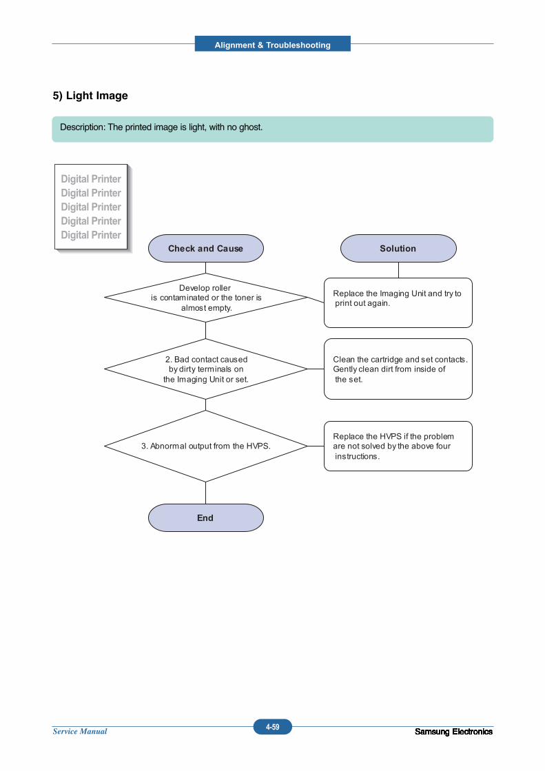
Service Manual
Alignment & Troubleshooting
4-59 Samsung ElectronicsSamsung ElectronicsSamsung ElectronicsSamsung ElectronicsSamsung ElectronicsSamsung ElectronicsSamsung ElectronicsSamsung ElectronicsSamsung ElectronicsSamsung Electronics
5) Light Image
Description: The printed image is light, with no ghost.
Digital PrinterDigital PrinterDigital PrinterDigital PrinterDigital Printer
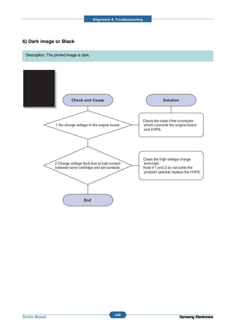
Service Manual
Alignment & Troubleshooting
4-60 Samsung ElectronicsSamsung ElectronicsSamsung ElectronicsSamsung ElectronicsSamsung ElectronicsSamsung ElectronicsSamsung ElectronicsSamsung ElectronicsSamsung ElectronicsSamsung Electronics
6) Dark image or Black
Description: The printed image is dark.
Digital PrinterDigital PrinterDigital PrinterDigital PrinterDigital Printer
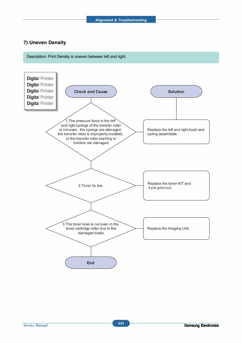
Service Manual
Alignment & Troubleshooting
4-61 Samsung ElectronicsSamsung ElectronicsSamsung ElectronicsSamsung ElectronicsSamsung ElectronicsSamsung ElectronicsSamsung ElectronicsSamsung ElectronicsSamsung ElectronicsSamsung Electronics
7) Uneven Density
Description: Print Density is uneven between left and right.
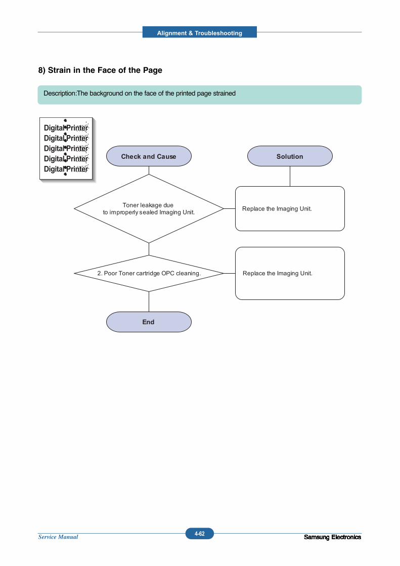
Service Manual
Alignment & Troubleshooting
4-62 Samsung ElectronicsSamsung ElectronicsSamsung ElectronicsSamsung ElectronicsSamsung ElectronicsSamsung ElectronicsSamsung ElectronicsSamsung ElectronicsSamsung ElectronicsSamsung Electronics
8) Strain in the Face of the Page
Description:The background on the face of the printed page strained
Digital PrinterDigital PrinterDigital PrinterDigital PrinterDigital Printer
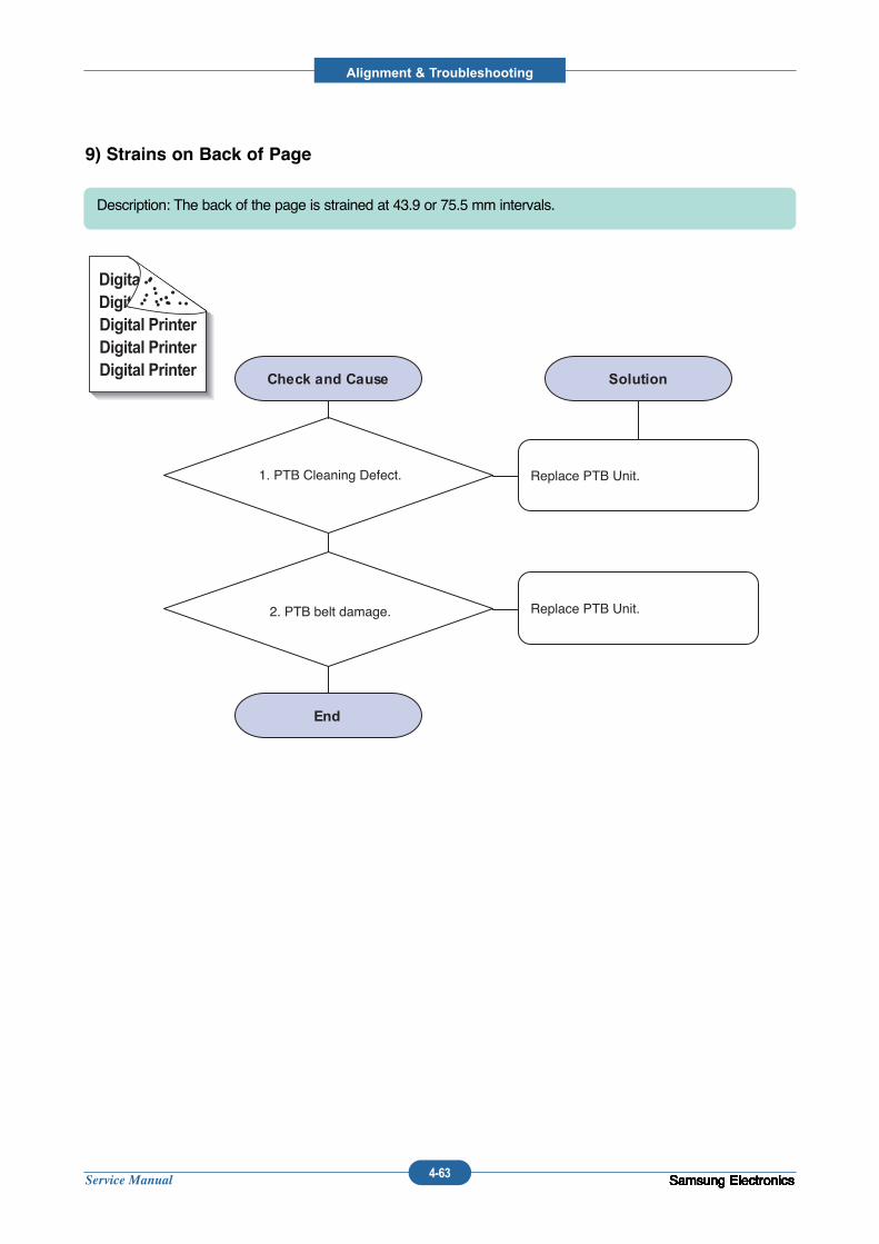
Service Manual
Alignment & Troubleshooting
4-63 Samsung ElectronicsSamsung ElectronicsSamsung ElectronicsSamsung ElectronicsSamsung ElectronicsSamsung ElectronicsSamsung ElectronicsSamsung ElectronicsSamsung ElectronicsSamsung Electronics
9) Strains on Back of Page
Description: The back of the page is strained at 43.9 or 75.5 mm intervals.
1. PTB Cleaning Defect.
2. PTB belt damage.
Replace PTB Unit.
Replace PTB Unit.
Digital Digital PriDigital PrinterDigital PrinterDigital Printer
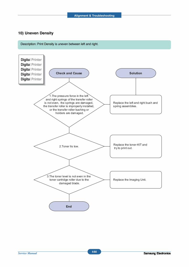
Service Manual
Alignment & Troubleshooting
4-64 Samsung ElectronicsSamsung ElectronicsSamsung ElectronicsSamsung ElectronicsSamsung ElectronicsSamsung ElectronicsSamsung ElectronicsSamsung ElectronicsSamsung ElectronicsSamsung Electronics
10) Uneven Density
Description: Print Density is uneven between left and right.
Service Manual
Alignment & Troubleshooting
4-65 Samsung ElectronicsSamsung ElectronicsSamsung ElectronicsSamsung ElectronicsSamsung ElectronicsSamsung ElectronicsSamsung ElectronicsSamsung ElectronicsSamsung ElectronicsSamsung Electronics
11) Blank Page Print out(1)
Description: Blank page is printed.
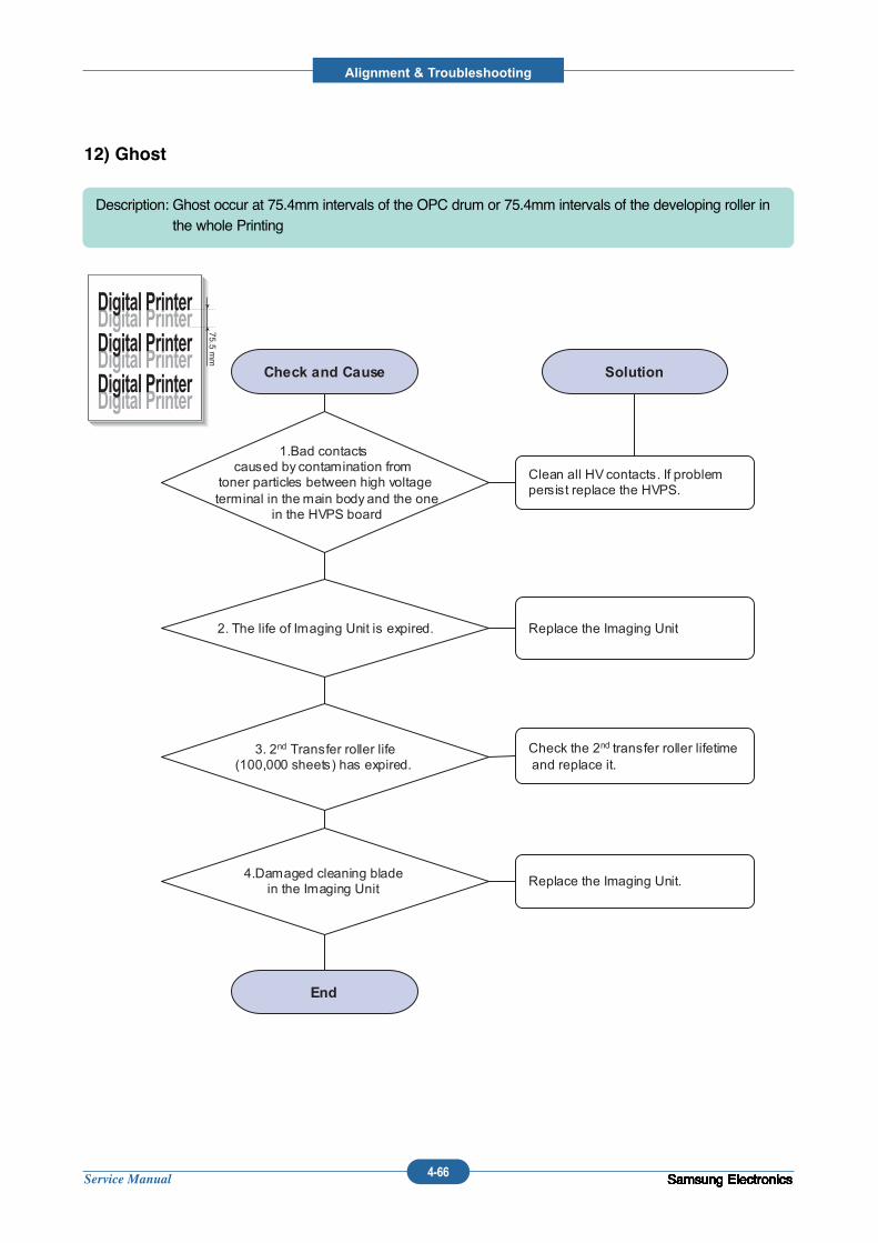
Service Manual
Alignment & Troubleshooting
4-66 Samsung ElectronicsSamsung ElectronicsSamsung ElectronicsSamsung ElectronicsSamsung ElectronicsSamsung ElectronicsSamsung ElectronicsSamsung ElectronicsSamsung ElectronicsSamsung Electronics
12) Ghost
Description: Ghost occur at 75.4mm intervals of the OPC drum or 75.4mm intervals of the developing roller inthe whole Printing
Digital Printer
Digital Printer
Digital Printer
Digital Printer
Digital Printer
Digital Printer
75.5 mm

Service Manual
Alignment & Troubleshooting
4-67 Samsung ElectronicsSamsung ElectronicsSamsung ElectronicsSamsung ElectronicsSamsung ElectronicsSamsung ElectronicsSamsung ElectronicsSamsung ElectronicsSamsung ElectronicsSamsung Electronics
4.2.3 The cause and solution of the paper feeding
1) Wrong Print Position
Description: Printing begins at wrong position on the paper.
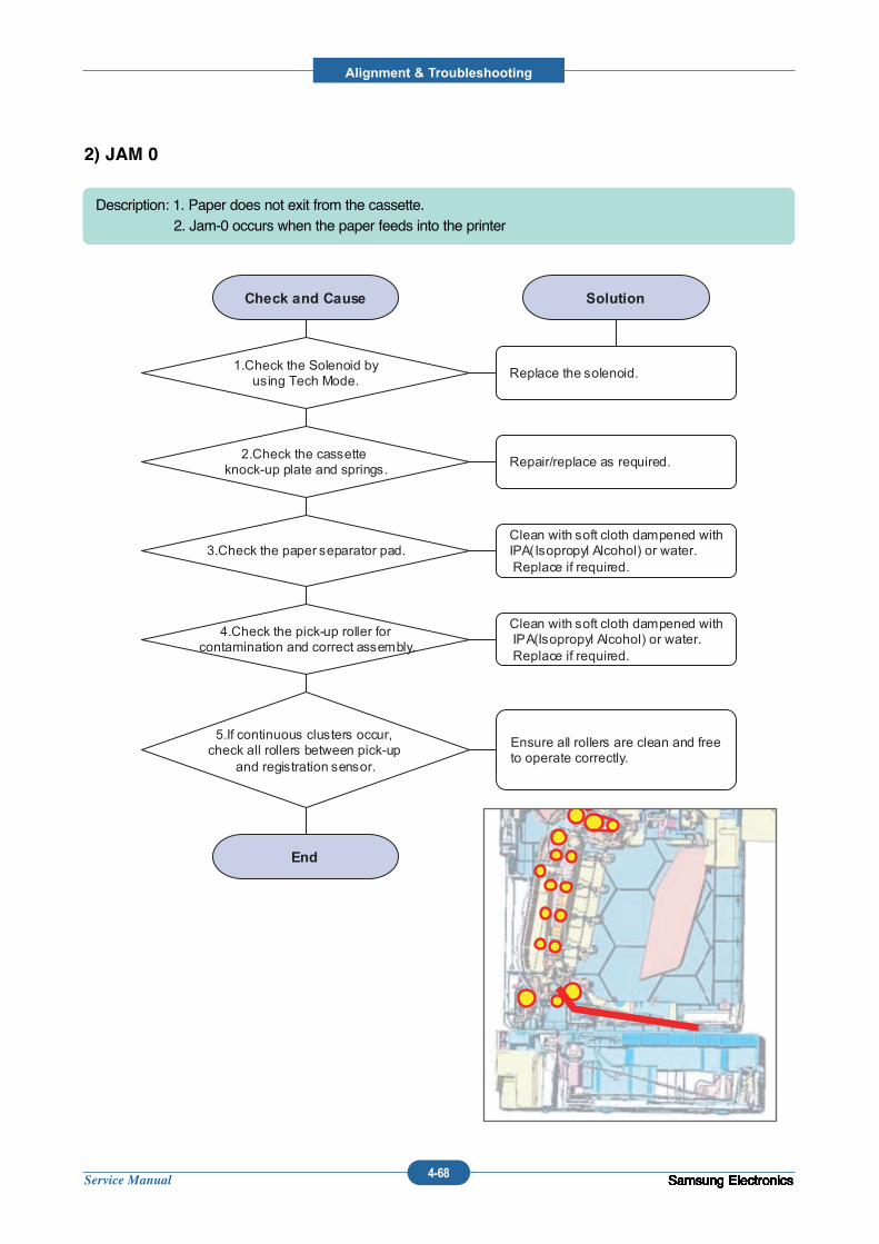
Service Manual
Alignment & Troubleshooting
4-68 Samsung ElectronicsSamsung ElectronicsSamsung ElectronicsSamsung ElectronicsSamsung ElectronicsSamsung ElectronicsSamsung ElectronicsSamsung ElectronicsSamsung ElectronicsSamsung Electronics
2) JAM 0
Description: 1. Paper does not exit from the cassette.2. Jam-0 occurs when the paper feeds into the printer
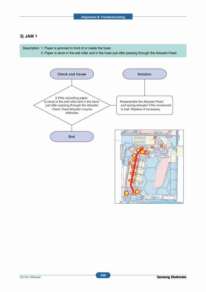
Service Manual
Alignment & Troubleshooting
4-69 Samsung ElectronicsSamsung ElectronicsSamsung ElectronicsSamsung ElectronicsSamsung ElectronicsSamsung ElectronicsSamsung ElectronicsSamsung ElectronicsSamsung ElectronicsSamsung Electronics
3) JAM 1
Description: 1. Paper is jammed in front of or inside the fuser.2. Paper is stuck in the exit roller and in the fuser just after passing through the Actuator-Feed
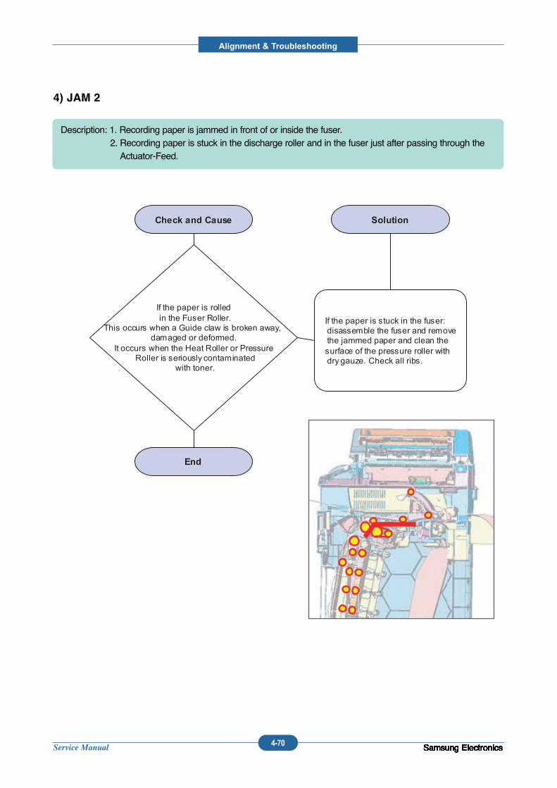
Service Manual
Alignment & Troubleshooting
4-70 Samsung ElectronicsSamsung ElectronicsSamsung ElectronicsSamsung ElectronicsSamsung ElectronicsSamsung ElectronicsSamsung ElectronicsSamsung ElectronicsSamsung ElectronicsSamsung Electronics
4) JAM 2
Description: 1. Recording paper is jammed in front of or inside the fuser. 2. Recording paper is stuck in the discharge roller and in the fuser just after passing through theActuator-Feed.
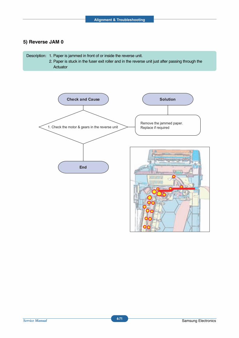
Service Manual
Alignment & Troubleshooting
4-71 Samsung Electronics
5) Reverse JAM 0
Description: 1. Paper is jammed in front of or inside the reverse unit.2. Paper is stuck in the fuser exit roller and in the reverse unit just after passing through theActuator
1. Check the motor & gears in the reverse unitRemove the jammed paper.Replace if required
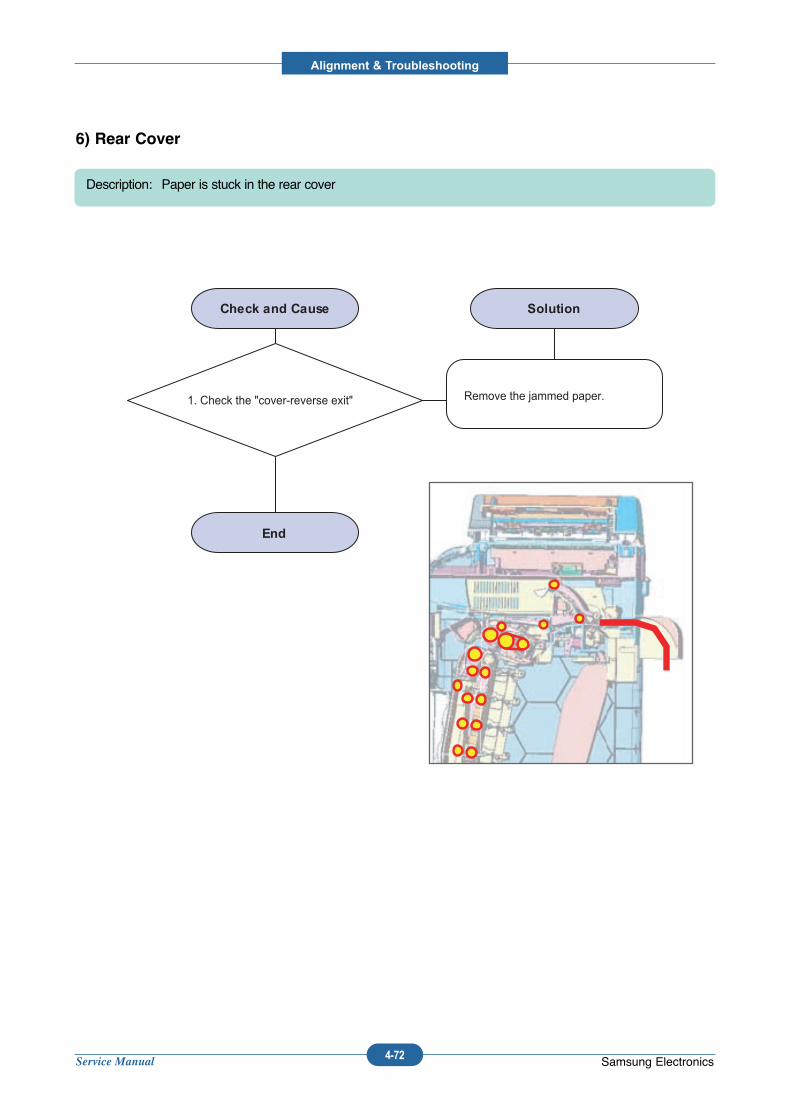
Service Manual
Alignment & Troubleshooting
4-72 Samsung Electronics
6) Rear Cover
Description: Paper is stuck in the rear cover
1. Check the "cover-reverse exit" Remove the jammed paper.
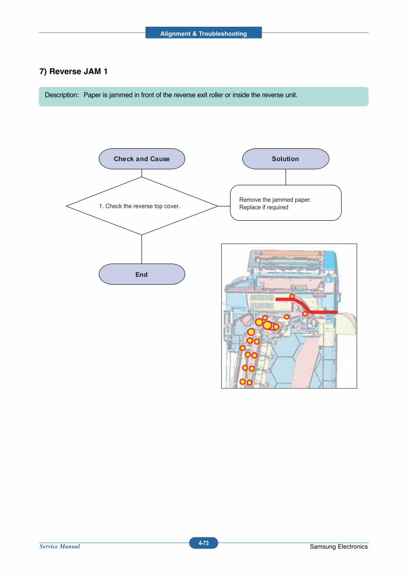
Service Manual
Alignment & Troubleshooting
4-73 Samsung Electronics
7) Reverse JAM 1
Description: Paper is jammed in front of the reverse exit roller or inside the reverse unit.
1. Check the reverse top cover.Remove the jammed paper.Replace if required
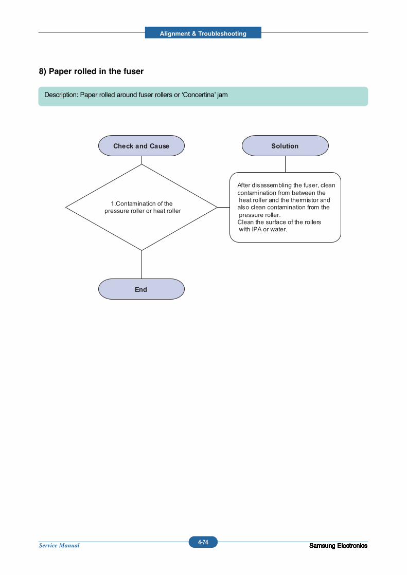
Service Manual
Alignment & Troubleshooting
4-74 Samsung ElectronicsSamsung ElectronicsSamsung ElectronicsSamsung ElectronicsSamsung ElectronicsSamsung ElectronicsSamsung ElectronicsSamsung ElectronicsSamsung ElectronicsSamsung ElectronicsSamsung Electronics
8) Paper rolled in the fuser
Description: Paper rolled around fuser rollers or ‘Concertina’ jam
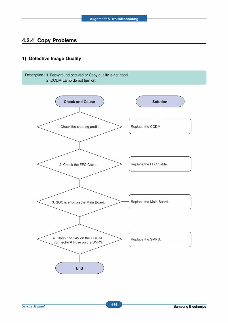
Service Manual
Alignment & Troubleshooting
4-75 Samsung Electronics
1) Defective Image Quality
Description : 1. Background occured or Copy quality is not good.2. CCDM Lamp do not turn on.
1. Check the shading profile. Replace the CCDM.
Replace the FFC Cable.2. Check the FFC Cable.
Replace the Main Board.3. SOC is error on the Main Board.
Replace the SMPS.4. Check the 24V on the CCD I/F connector & Fuse on the SMPS.
Samsung ElectronicsSamsung Electronics
4.2.4 Copy Problems
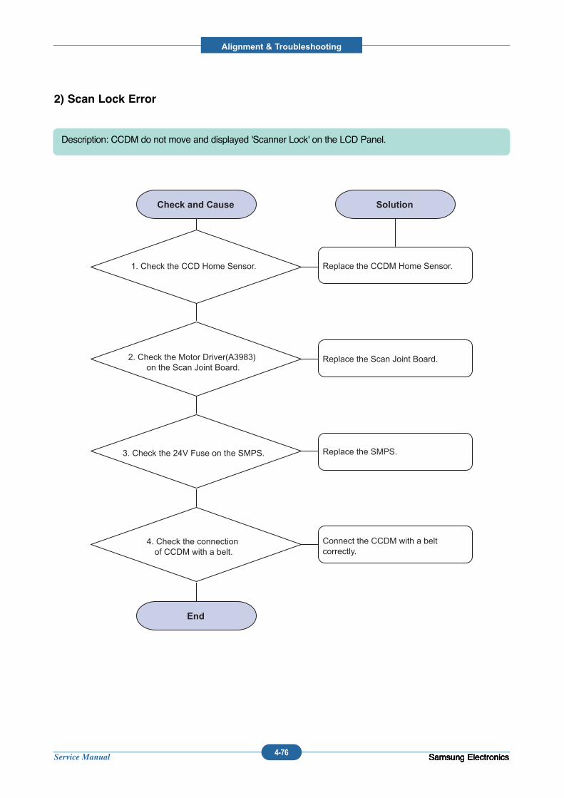
Service Manual
Alignment & Troubleshooting
4-76 Samsung ElectronicsSamsung ElectronicsSamsung ElectronicsSamsung Electronics
2) Scan Lock Error
Description: CCDM do not move and displayed 'Scanner Lock' on the LCD Panel.
1. Check the CCD Home Sensor. Replace the CCDM Home Sensor.
Replace the Scan Joint Board.2. Check the Motor Driver(A3983) on the Scan Joint Board.
Replace the SMPS.3. Check the 24V Fuse on the SMPS.
Connect the CCDM with a belt correctly.
4. Check the connection of CCDM with a belt.
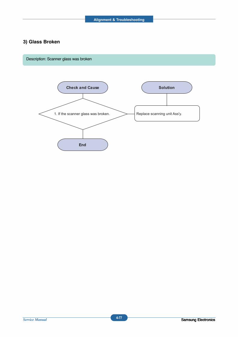
Service Manual
Alignment & Troubleshooting
4-77 Samsung ElectronicsSamsung ElectronicsSamsung ElectronicsSamsung Electronics
3) Glass Broken
Description: Scanner glass was broken
1. If the scanner glass was broken. Replace scanning unit Ass'y.
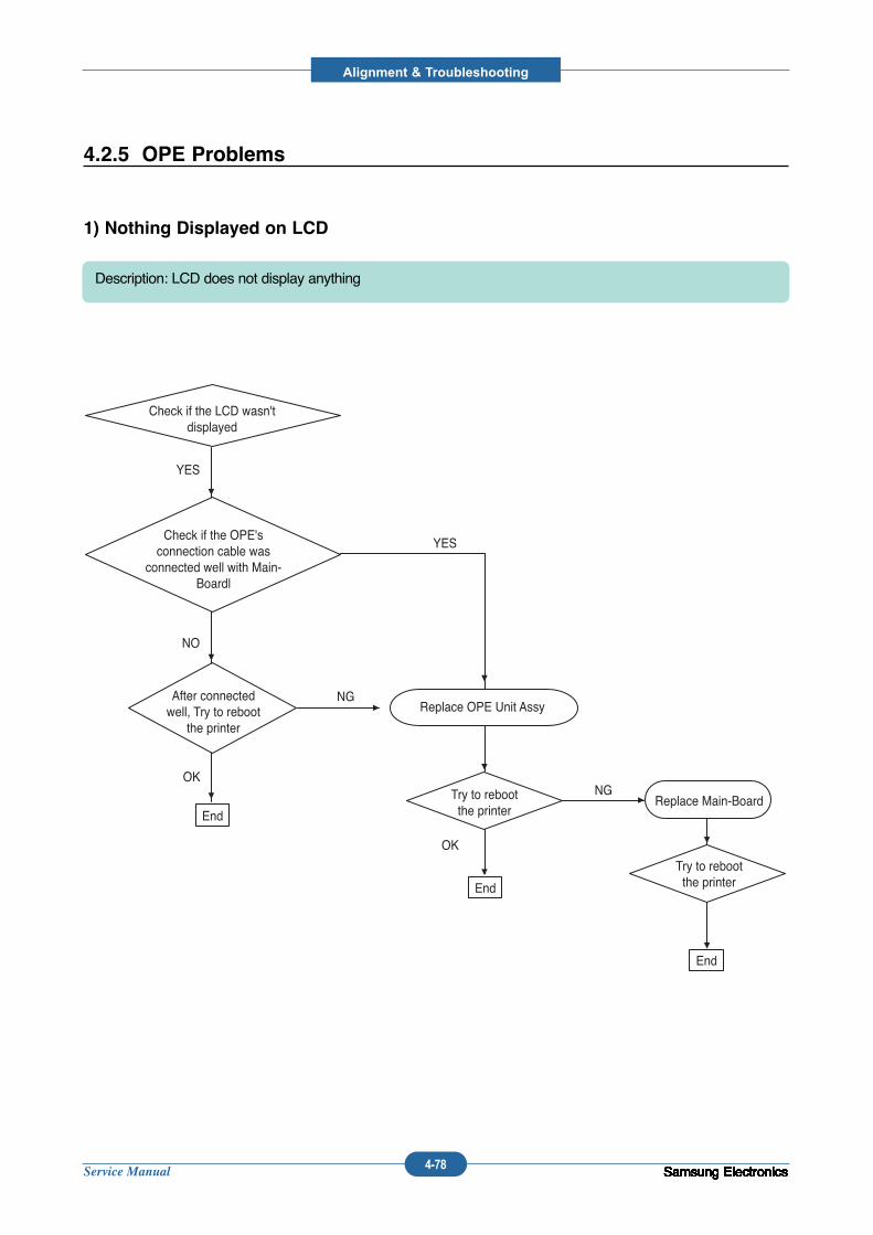
Service Manual
Alignment & Troubleshooting
4-78 Samsung ElectronicsSamsung ElectronicsSamsung ElectronicsSamsung ElectronicsSamsung ElectronicsSamsung ElectronicsSamsung ElectronicsSamsung ElectronicsSamsung ElectronicsSamsung ElectronicsSamsung ElectronicsSamsung ElectronicsSamsung ElectronicsSamsung Electronics
4.2.5 OPE Problems
1) Nothing Displayed on LCD
Description: LCD does not display anything
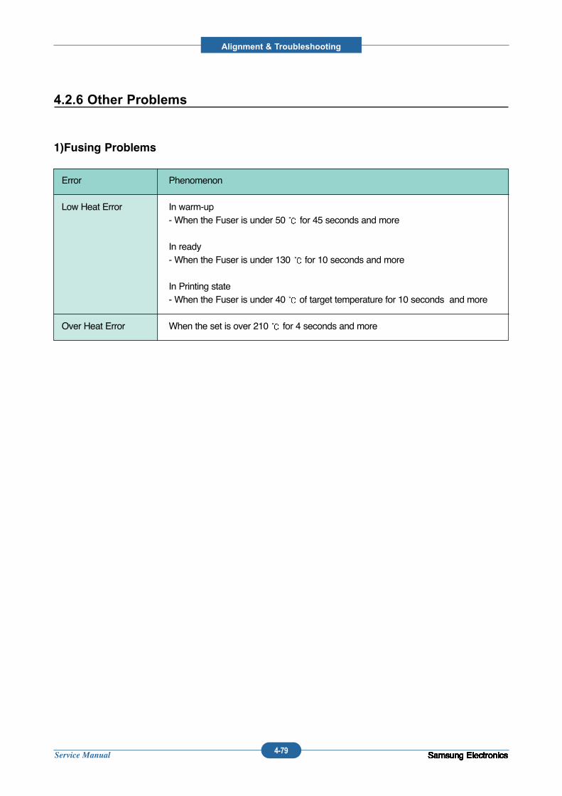
Service Manual
Alignment & Troubleshooting
4-79 Samsung ElectronicsSamsung ElectronicsSamsung ElectronicsSamsung ElectronicsSamsung ElectronicsSamsung ElectronicsSamsung ElectronicsSamsung ElectronicsSamsung ElectronicsSamsung ElectronicsSamsung ElectronicsSamsung ElectronicsSamsung ElectronicsSamsung ElectronicsSamsung Electronics
Error Phenomenon
Low Heat Error In warm-up- When the Fuser is under 50 for 45 seconds and more
In ready- When the Fuser is under 130 for 10 seconds and more
In Printing state- When the Fuser is under 40 of target temperature for 10 seconds and more
Over Heat Error When the set is over 210 for 4 seconds and more
4.2.6 Other Problems
1)Fusing Problems
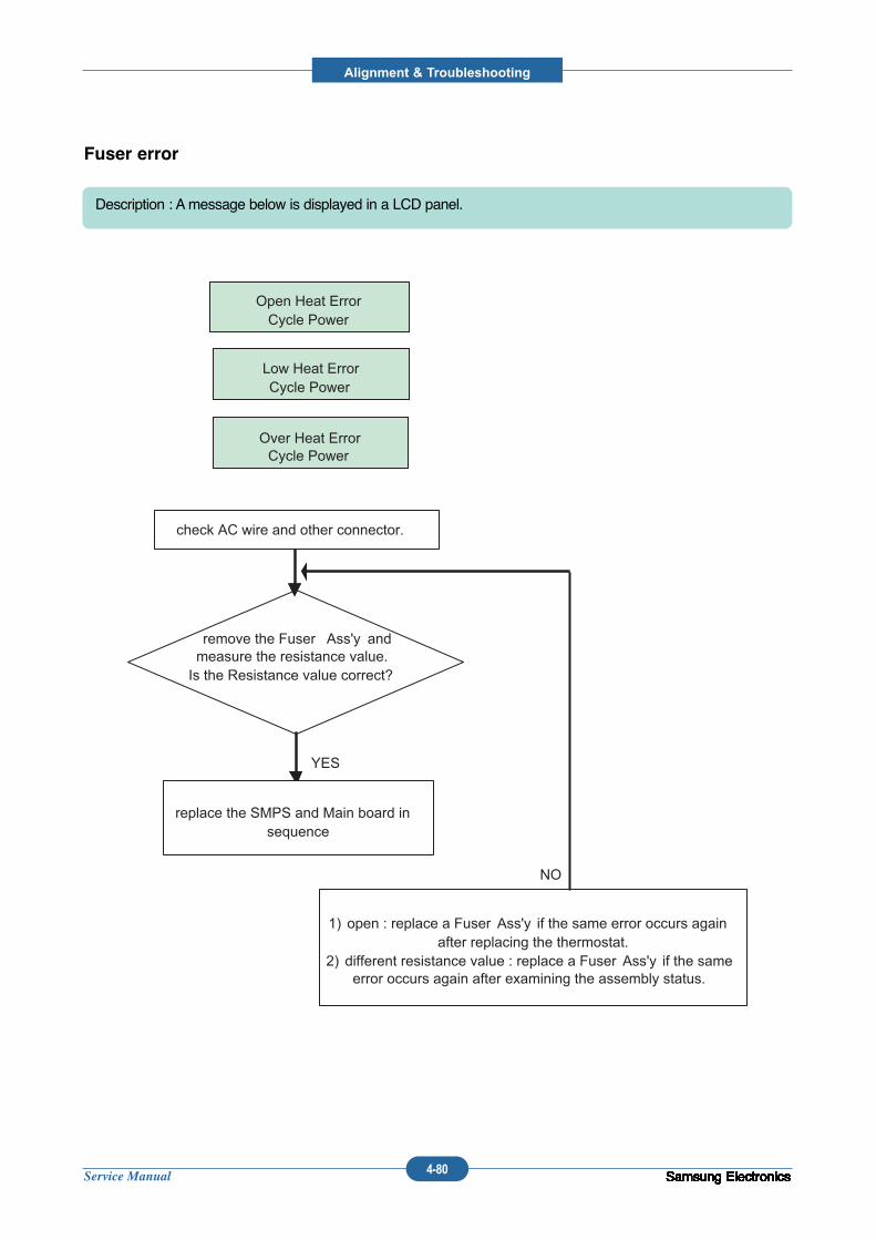
Service Manual
Alignment & Troubleshooting
4-80 Samsung ElectronicsSamsung ElectronicsSamsung ElectronicsSamsung ElectronicsSamsung ElectronicsSamsung ElectronicsSamsung ElectronicsSamsung ElectronicsSamsung ElectronicsSamsung ElectronicsSamsung ElectronicsSamsung ElectronicsSamsung ElectronicsSamsung ElectronicsSamsung Electronics
Fuser error
Description : Amessage below is displayed in a LCD panel.
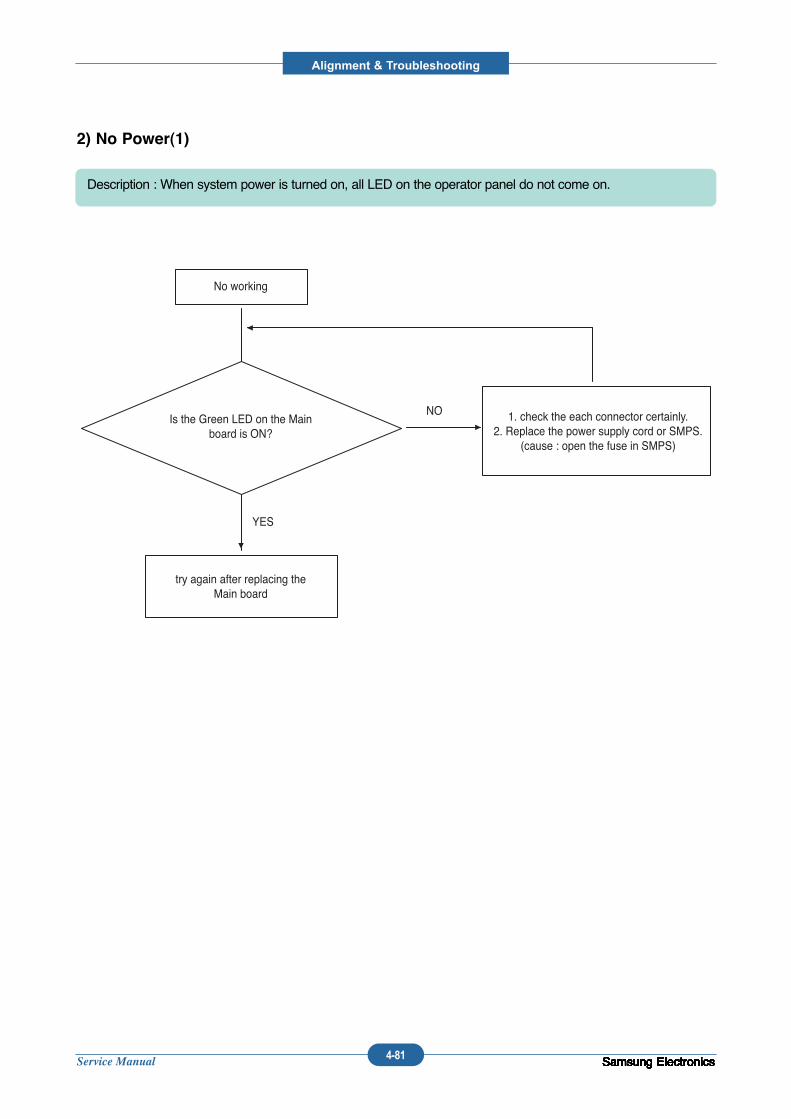
Service Manual
Alignment & Troubleshooting
4-81 Samsung ElectronicsSamsung ElectronicsSamsung ElectronicsSamsung ElectronicsSamsung ElectronicsSamsung ElectronicsSamsung ElectronicsSamsung ElectronicsSamsung ElectronicsSamsung ElectronicsSamsung ElectronicsSamsung ElectronicsSamsung ElectronicsSamsung ElectronicsSamsung Electronics
2) No Power(1)
Description : When system power is turned on, all LED on the operator panel do not come on.
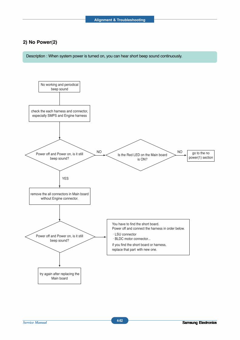
Service Manual
Alignment & Troubleshooting
4-82 Samsung ElectronicsSamsung ElectronicsSamsung ElectronicsSamsung ElectronicsSamsung ElectronicsSamsung ElectronicsSamsung ElectronicsSamsung ElectronicsSamsung ElectronicsSamsung ElectronicsSamsung ElectronicsSamsung ElectronicsSamsung ElectronicsSamsung ElectronicsSamsung Electronics
2) No Power(2)
Description : When system power is turned on, you can hear short beep sound continuously.
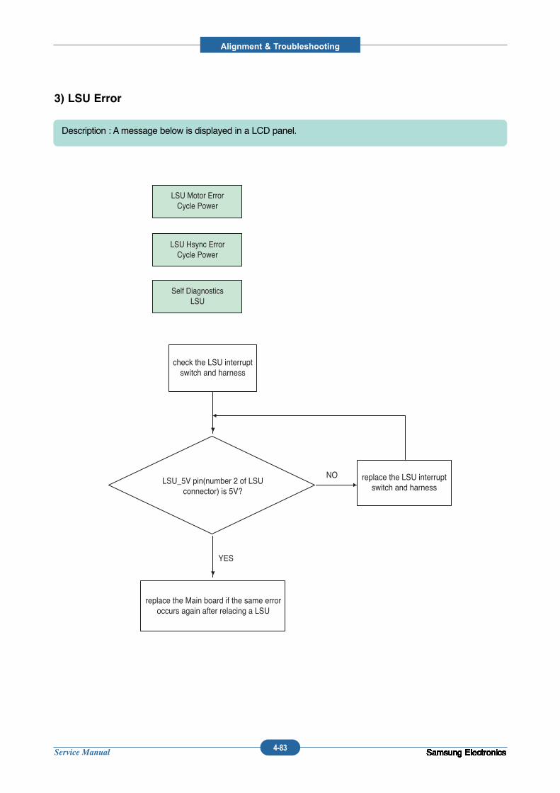
Service Manual
Alignment & Troubleshooting
4-83 Samsung ElectronicsSamsung ElectronicsSamsung ElectronicsSamsung ElectronicsSamsung ElectronicsSamsung ElectronicsSamsung ElectronicsSamsung ElectronicsSamsung ElectronicsSamsung ElectronicsSamsung ElectronicsSamsung ElectronicsSamsung ElectronicsSamsung ElectronicsSamsung Electronics
3) LSU Error
Description : Amessage below is displayed in a LCD panel.
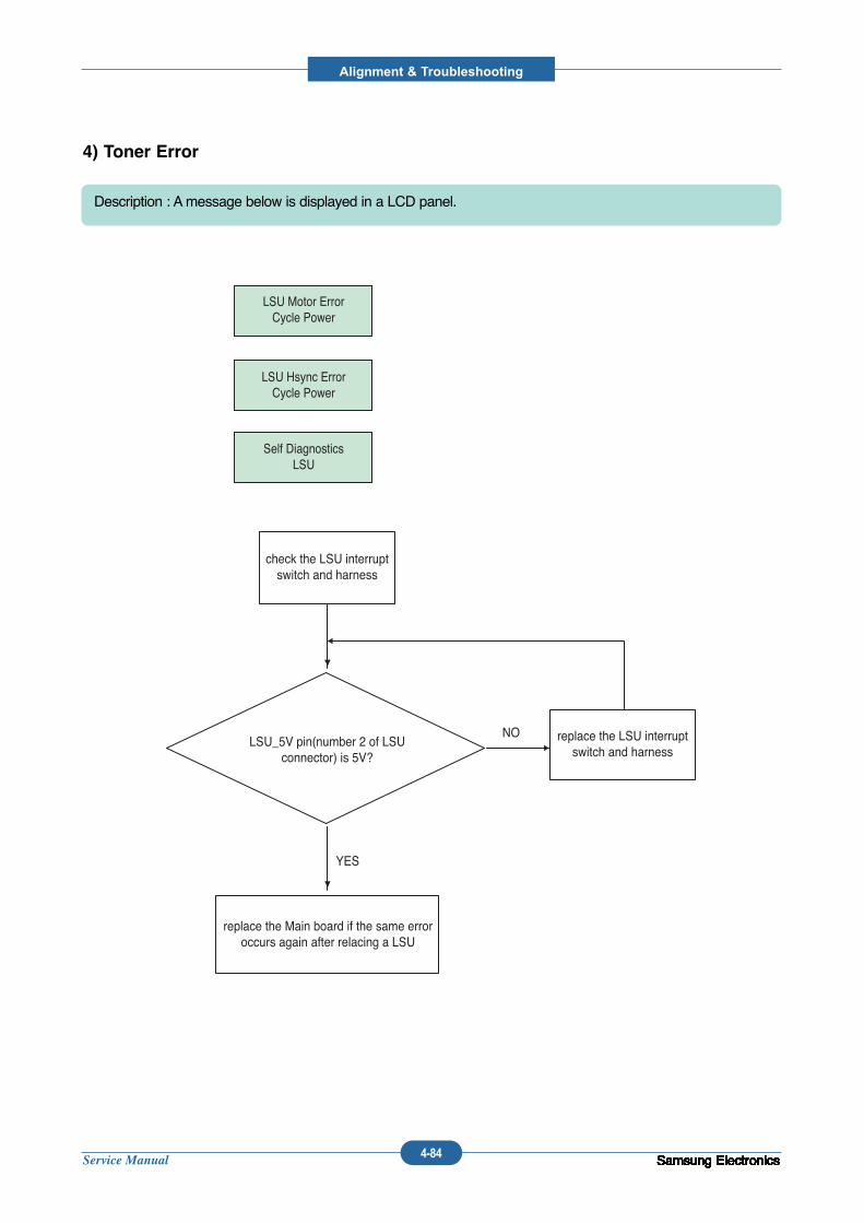
Service Manual
Alignment & Troubleshooting
4-84 Samsung ElectronicsSamsung ElectronicsSamsung ElectronicsSamsung ElectronicsSamsung ElectronicsSamsung ElectronicsSamsung ElectronicsSamsung ElectronicsSamsung ElectronicsSamsung ElectronicsSamsung ElectronicsSamsung ElectronicsSamsung ElectronicsSamsung ElectronicsSamsung ElectronicsSamsung Electronics
4) Toner Error
Description : Amessage below is displayed in a LCD panel.
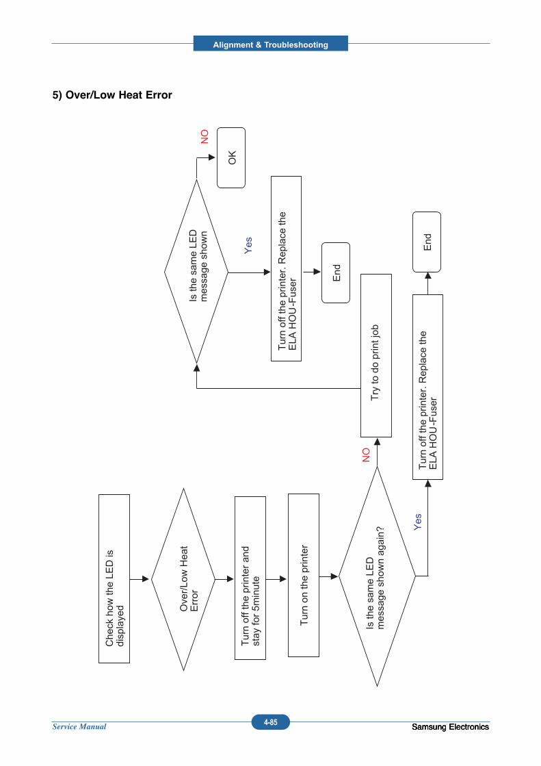
Service Manual
Alignment & Troubleshooting
4-85 Samsung ElectronicsSamsung ElectronicsSamsung Electronics
5) Over/Low Heat Error
Check how
the LE
D is
displayed Over/Low Heat
Error
Yes
NO
End
Turn off the printer and
stay for 5m
inute
Turn on the printer
Is the same LE
D
message shown again?
Turn off the printer. Replace the
ELA
HOU-FuserT
ry to do print job
Is the same LE
D
message shown
Turn off the printer. Replace the
ELA
HOU-Fuser E
nd
Yes
OK
NO
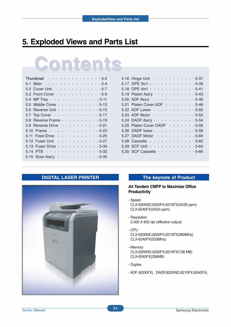
Service Manual
ExplodedView and Parts list
5-1 Samsung Electronics
Thumbnail 5-25.1 Main 5-45.2 Cover Unit 5-75.3 Front Cover 5-95.4 MP Tray 5-115.5 Middle Cover 5-135.6 Reverse Unit 5-155.7 Top Cover 5-175.8 Reverse Frame 5-195.9 Reverse Drive 5-215.10 Frame 5-235.11 Feed Drive 5-255.12 Fuser Unit 5-275.13 Fuser Drive 5-305.14 PTB 5-325.15 Scan Ass'y 5-35
5.16 Hinge Unit 5-375.17 OPE 3in1 5-395.18 OPE 4in1 5-415.19 Platen Ass'y 5-435.20 ADF Ass'y 5-465.21 Platen Cover ADF 5-485.22 ADF Lower 5-505.23 ADF Motor 5-525.24 DADF Ass'y 5-545.25 Platen Cover DADF 5-565.26 DADF lower 5-585.27 DADF Motor 5-605.28 Cassette 5-625.29 SCF Unit 5-645.30 SCF Cassette 5-66
ContentsContents5. Exploded Views and Parts List
DIGITAL LASER PRINTER The keynote of Product
A4 Tandem CMFP to Maximize OfficeProductivity
- Speed CLX-6200ND,6200FX,6210FX(20/20 ppm)CLX-6240FX(24/24 ppm)
- Resolution 2,400 X 600 dpi (effective output)
- CPU CLX-6200ND,6200FX,6210FX(360MHz)CLX-6240FX(533MHz)
- Memory CLX-6200ND,6200FX,6210FX(128 MB)CLX-6240FX(256MB)
- Duplex
- ADF (6200FX) , DADF(6200ND,6210FX,6240FX)
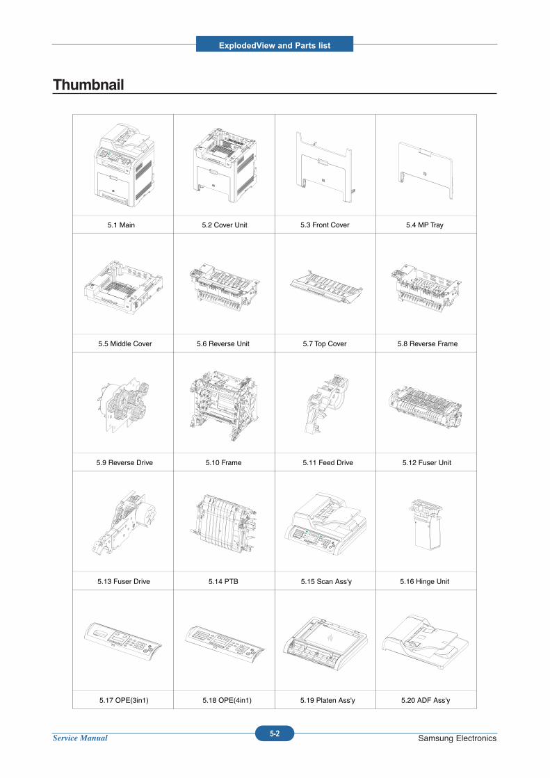
Service Manual
ExplodedView and Parts list
5-2 Samsung Electronics
Thumbnail
5.1 Main 5.2 Cover Unit 5.3 Front Cover 5.4 MP Tray
5.5 Middle Cover 5.6 Reverse Unit 5.7 Top Cover 5.8 Reverse Frame
5.9 Reverse Drive 5.10 Frame 5.11 Feed Drive 5.12 Fuser Unit
5.13 Fuser Drive 5.14 PTB 5.15 Scan Ass'y 5.16 Hinge Unit
5.17 OPE(3in1) 5.18 OPE(4in1) 5.19 Platen Ass'y 5.20 ADF Ass'y
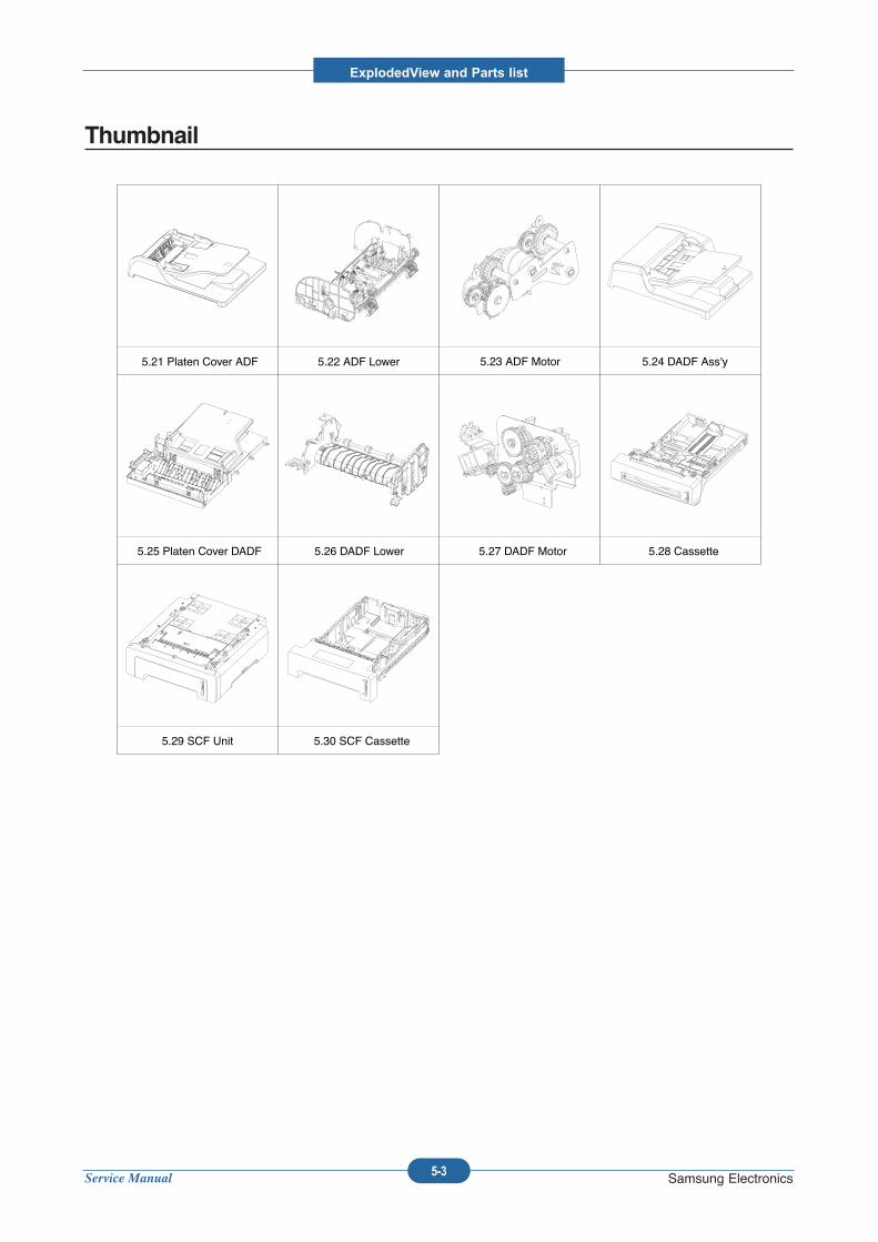
Service Manual
ExplodedView and Parts list
5-3 Samsung Electronics
Thumbnail
5.21 Platen Cover ADF 5.22 ADF Lower 5.23 ADF Motor 5.24 DADF Ass'y
5.25 Platen Cover DADF 5.26 DADF Lower 5.27 DADF Motor 5.28 Cassette
5.29 SCF Unit 5.30 SCF Cassette
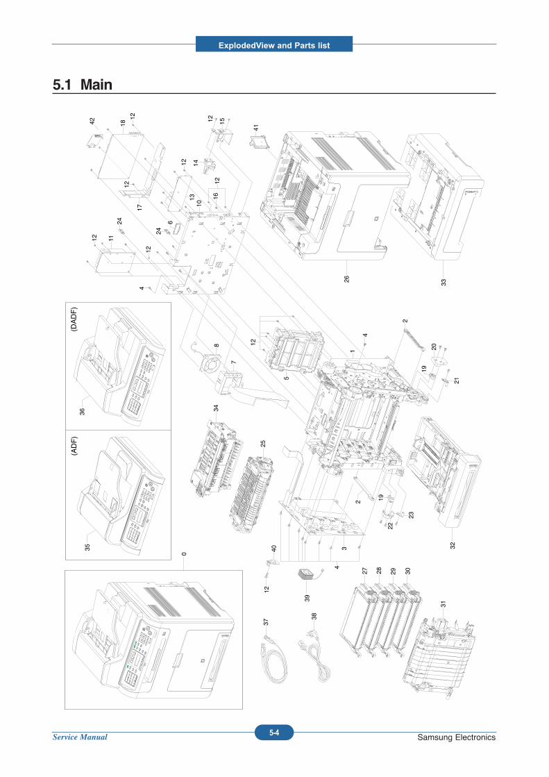
Service Manual
ExplodedView and Parts list
5-4 Samsung Electronics
5.1 Main
0
43
2 19
22
23
21
19
20
2
1
4
5
128
7
10
4
1112
24
12
24
6
13
17
18
1212
1612
14
1512
12
25
26
30
31
27 28 29
32
34
33
3536
(ADF)
(DADF)
37
3839
1240
41
42
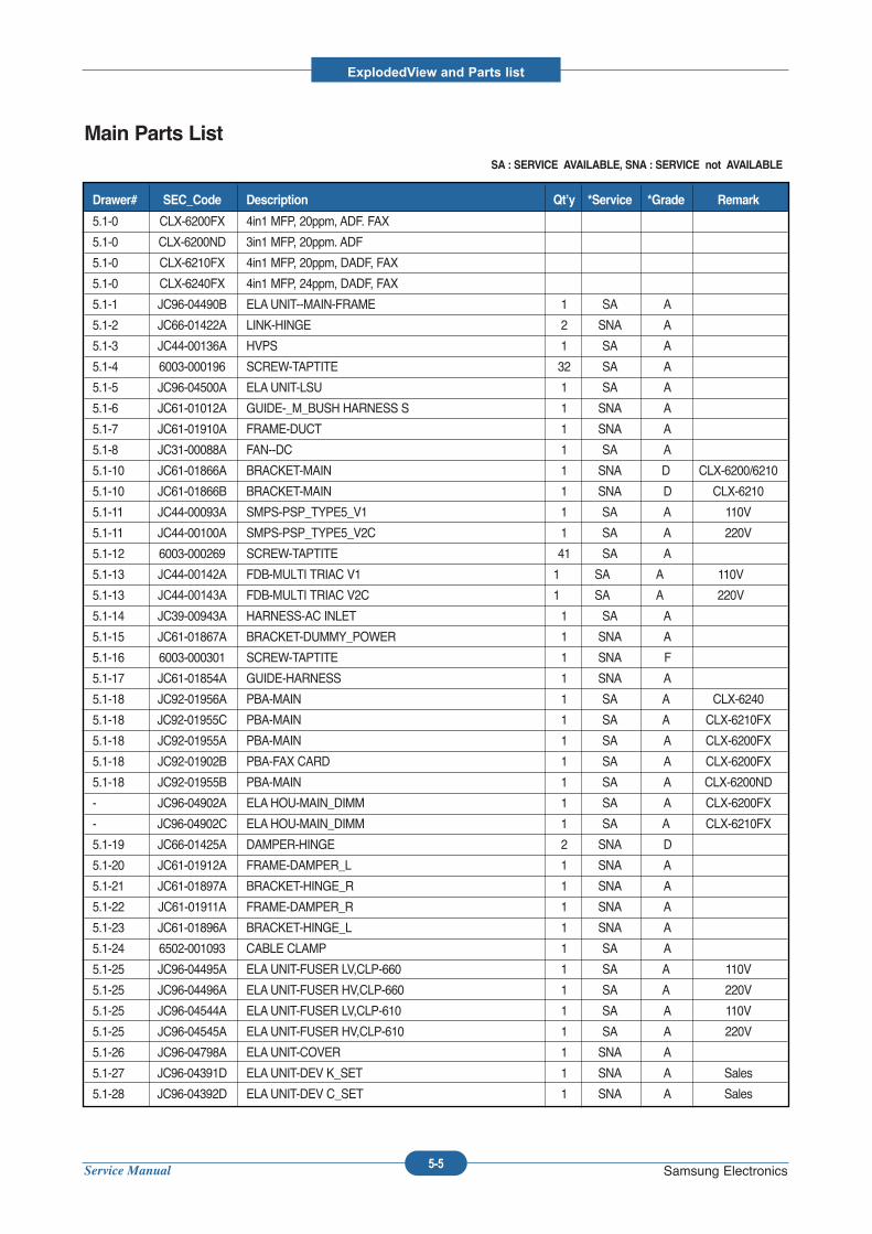
Service Manual
ExplodedView and Parts list
5-5 Samsung Electronics
Main Parts ListSA : SERVICE AVAILABLE, SNA : SERVICE not AVAILABLE
5.1-0 CLX-6200FX 4in1 MFP, 20ppm, ADF. FAX
5.1-0 CLX-6200ND 3in1 MFP, 20ppm. ADF
5.1-0 CLX-6210FX 4in1 MFP, 20ppm, DADF, FAX
5.1-0 CLX-6240FX 4in1 MFP, 24ppm, DADF, FAX
5.1-1 JC96-04490B ELAUNIT--MAIN-FRAME 1 SA A
5.1-2 JC66-01422A LINK-HINGE 2 SNA A
5.1-3 JC44-00136A HVPS 1 SA A
5.1-4 6003-000196 SCREW-TAPTITE 32 SA A
5.1-5 JC96-04500A ELAUNIT-LSU 1 SA A
5.1-6 JC61-01012A GUIDE-_M_BUSH HARNESS S 1 SNA A
5.1-7 JC61-01910A FRAME-DUCT 1 SNA A
5.1-8 JC31-00088A FAN--DC 1 SA A
5.1-10 JC61-01866A BRACKET-MAIN 1 SNA D CLX-6200/6210
5.1-10 JC61-01866B BRACKET-MAIN 1 SNA D CLX-6210
5.1-11 JC44-00093A SMPS-PSP_TYPE5_V1 1 SA A 110V
5.1-11 JC44-00100A SMPS-PSP_TYPE5_V2C 1 SA A 220V
5.1-12 6003-000269 SCREW-TAPTITE 41 SA A
5.1-13 JC44-00142A FDB-MULTI TRIAC V1 1 SA A 110V
5.1-13 JC44-00143A FDB-MULTI TRIAC V2C 1 SA A 220V
5.1-14 JC39-00943A HARNESS-AC INLET 1 SA A
5.1-15 JC61-01867A BRACKET-DUMMY_POWER 1 SNA A
5.1-16 6003-000301 SCREW-TAPTITE 1 SNA F
5.1-17 JC61-01854A GUIDE-HARNESS 1 SNA A
5.1-18 JC92-01956A PBA-MAIN 1 SA A CLX-6240
5.1-18 JC92-01955C PBA-MAIN 1 SA A CLX-6210FX
5.1-18 JC92-01955A PBA-MAIN 1 SA A CLX-6200FX
5.1-18 JC92-01902B PBA-FAX CARD 1 SA A CLX-6200FX
5.1-18 JC92-01955B PBA-MAIN 1 SA A CLX-6200ND
- JC96-04902A ELAHOU-MAIN_DIMM 1 SA A CLX-6200FX
- JC96-04902C ELAHOU-MAIN_DIMM 1 SA A CLX-6210FX
5.1-19 JC66-01425A DAMPER-HINGE 2 SNA D
5.1-20 JC61-01912A FRAME-DAMPER_L 1 SNA A
5.1-21 JC61-01897A BRACKET-HINGE_R 1 SNA A
5.1-22 JC61-01911A FRAME-DAMPER_R 1 SNA A
5.1-23 JC61-01896A BRACKET-HINGE_L 1 SNA A
5.1-24 6502-001093 CABLE CLAMP 1 SA A
5.1-25 JC96-04495A ELAUNIT-FUSER LV,CLP-660 1 SA A 110V
5.1-25 JC96-04496A ELAUNIT-FUSER HV,CLP-660 1 SA A 220V
5.1-25 JC96-04544A ELAUNIT-FUSER LV,CLP-610 1 SA A 110V
5.1-25 JC96-04545A ELAUNIT-FUSER HV,CLP-610 1 SA A 220V
5.1-26 JC96-04798A ELAUNIT-COVER 1 SNA A
5.1-27 JC96-04391D ELAUNIT-DEV K_SET 1 SNA A Sales
5.1-28 JC96-04392D ELAUNIT-DEV C_SET 1 SNA A Sales
Drawer# SEC_Code Description Qt’y *Service *Grade Remark
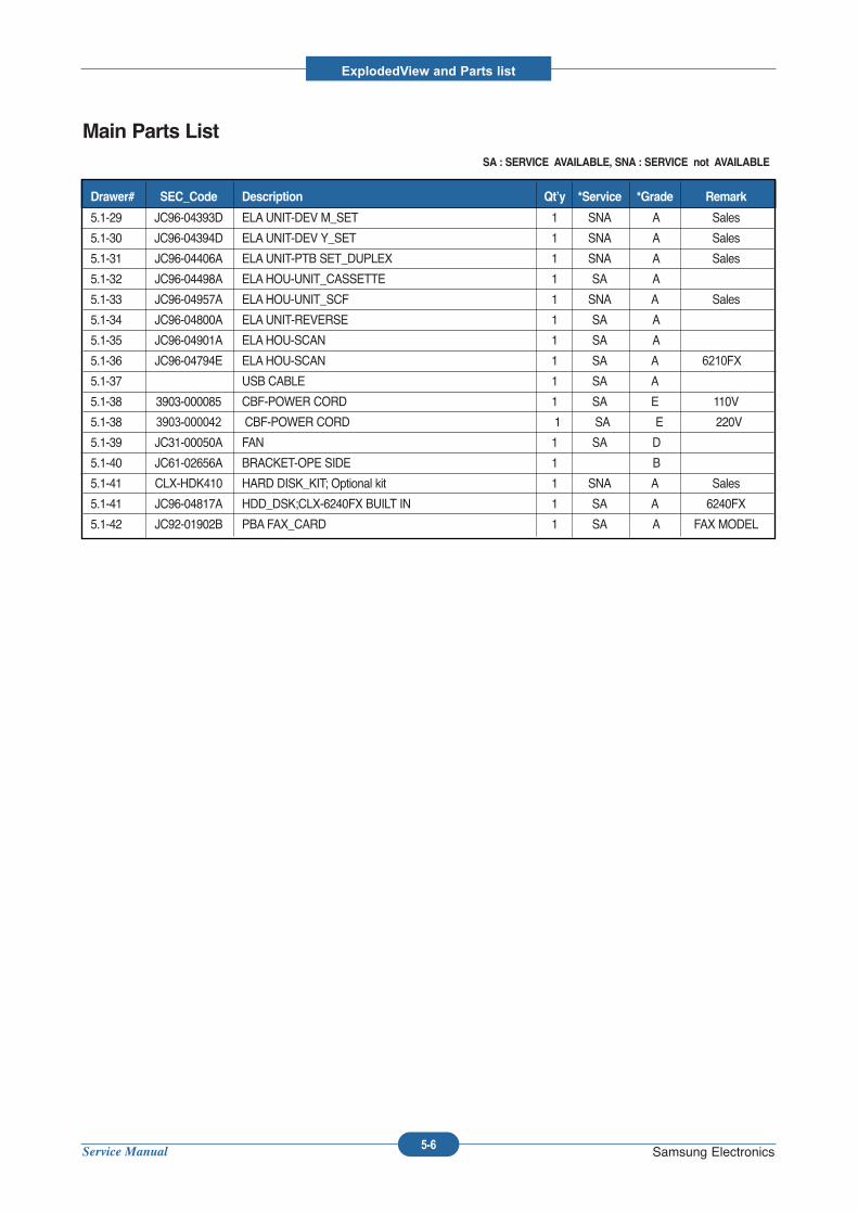
Service Manual
ExplodedView and Parts list
5-6 Samsung Electronics
Main Parts ListSA : SERVICE AVAILABLE, SNA : SERVICE not AVAILABLE
5.1-29 JC96-04393D ELAUNIT-DEV M_SET 1 SNA A Sales
5.1-30 JC96-04394D ELAUNIT-DEV Y_SET 1 SNA A Sales
5.1-31 JC96-04406A ELAUNIT-PTB SET_DUPLEX 1 SNA A Sales
5.1-32 JC96-04498A ELAHOU-UNIT_CASSETTE 1 SA A
5.1-33 JC96-04957A ELAHOU-UNIT_SCF 1 SNA A Sales
5.1-34 JC96-04800A ELAUNIT-REVERSE 1 SA A
5.1-35 JC96-04901A ELAHOU-SCAN 1 SA A
5.1-36 JC96-04794E ELAHOU-SCAN 1 SA A 6210FX
5.1-37 USB CABLE 1 SA A
5.1-38 3903-000085 CBF-POWER CORD 1 SA E 110V
5.1-38 3903-000042 CBF-POWER CORD 1 SA E 220V
5.1-39 JC31-00050A FAN 1 SA D
5.1-40 JC61-02656A BRACKET-OPE SIDE 1 B
5.1-41 CLX-HDK410 HARD DISK_KIT; Optional kit 1 SNA A Sales
5.1-41 JC96-04817A HDD_DSK;CLX-6240FX BUILT IN 1 SA A 6240FX
5.1-42 JC92-01902B PBA FAX_CARD 1 SA A FAX MODEL
Drawer# SEC_Code Description Qt’y *Service *Grade Remark
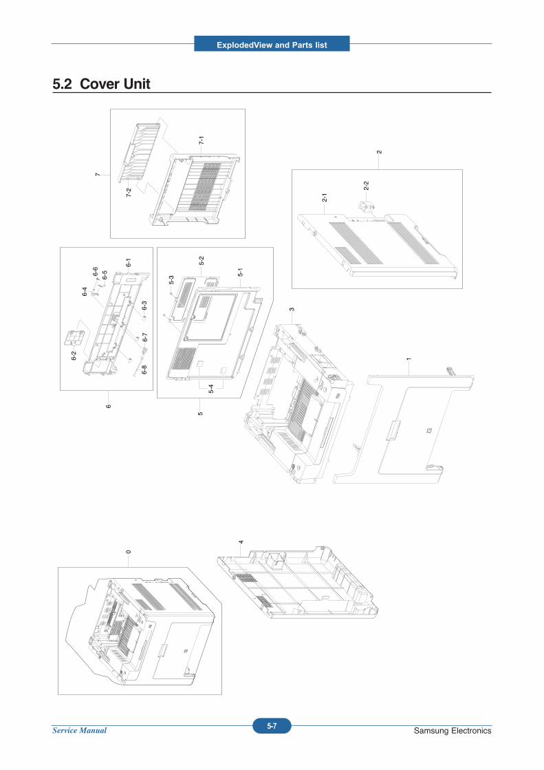
Service Manual
ExplodedView and Parts list
5-7 Samsung Electronics
5.2 Cover Unit
0
1
2
2-1
2-2
3
4
5
5-1
5-2
5-3
6
6-1
6-2
6-3
7
7-1
7-2
6-4
6-6
6-5
6-7
6-8
5-4
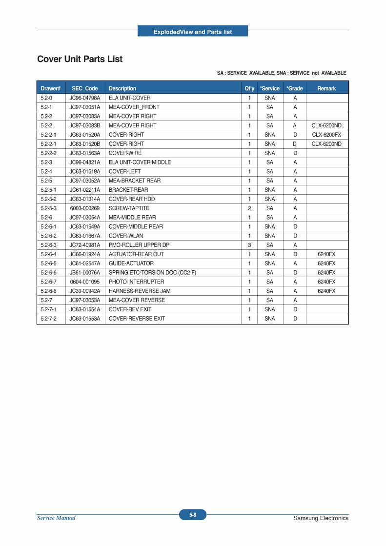
Service Manual
ExplodedView and Parts list
5-8 Samsung Electronics
Cover Unit Parts ListSA : SERVICE AVAILABLE, SNA : SERVICE not AVAILABLE
5.2-0 JC96-04798A ELAUNIT-COVER 1 SNA A
5.2-1 JC97-03051A MEA-COVER_FRONT 1 SA A
5.2-2 JC97-03083A MEA-COVER RIGHT 1 SA A
5.2-2 JC97-03083B MEA-COVER RIGHT 1 SA A CLX-6200ND
5.2-2-1 JC63-01520A COVER-RIGHT 1 SNA D CLX-6200FX
5.2-2-1 JC63-01520B COVER-RIGHT 1 SNA D CLX-6200ND
5.2-2-2 JC63-01563A COVER-WIRE 1 SNA D
5.2-3 JC96-04821A ELAUNIT-COVER MIDDLE 1 SA A
5.2-4 JC63-01519A COVER-LEFT 1 SA A
5.2-5 JC97-03052A MEA-BRACKET REAR 1 SA A
5.2-5-1 JC61-02211A BRACKET-REAR 1 SNA A
5.2-5-2 JC63-01314A COVER-REAR HDD 1 SNA A
5.2-5-3 6003-000269 SCREW-TAPTITE 2 SA A
5.2-6 JC97-03054A MEA-MIDDLE REAR 1 SA A
5.2-6-1 JC63-01549A COVER-MIDDLE REAR 1 SNA D
5.2-6-2 JC63-01667A COVER-WLAN 1 SNA D
5.2-6-3 JC72-40981A PMO-ROLLER UPPER DP 3 SA A
5.2-6-4 JC66-01924A ACTUATOR-REAR OUT 1 SNA D 6240FX
5.2-6-5 JC61-02547A GUIDE-ACTUATOR 1 SNA A 6240FX
5.2-6-6 JB61-00076A SPRING ETC-TORSION DOC (CC2-F) 1 SA D 6240FX
5.2-6-7 0604-001095 PHOTO-INTERRUPTER 1 SA A 6240FX
5.2-6-8 JC39-00942A HARNESS-REVERSE JAM 1 SA A 6240FX
5.2-7 JC97-03053A MEA-COVER REVERSE 1 SA A
5.2-7-1 JC63-01554A COVER-REV EXIT 1 SNA D
5.2-7-2 JC63-01553A COVER-REVERSE EXIT 1 SNA D
Drawer# SEC_Code Description Qt’y *Service *Grade Remark
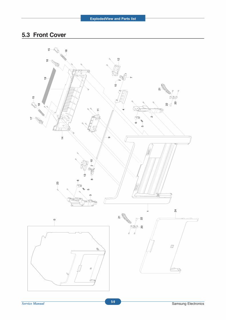
Service Manual
ExplodedView and Parts list
5-9 Samsung Electronics
5.3 Front Cover
0
13
35
6 810
1 24
2
22 20
21
5
6
9
11 4
10
7
12
14
181516
18
1715
19
2220
21
23
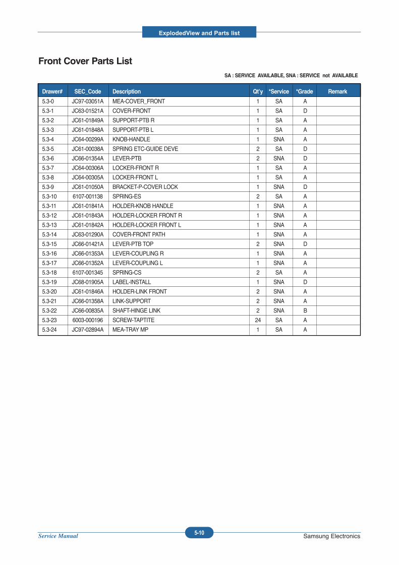
Service Manual
ExplodedView and Parts list
5-10 Samsung Electronics
Front Cover Parts ListSA : SERVICE AVAILABLE, SNA : SERVICE not AVAILABLE
5.3-0 JC97-03051A MEA-COVER_FRONT 1 SA A
5.3-1 JC63-01521A COVER-FRONT 1 SA D
5.3-2 JC61-01849A SUPPORT-PTB R 1 SA A
5.3-3 JC61-01848A SUPPORT-PTB L 1 SA A
5.3-4 JC64-00299A KNOB-HANDLE 1 SNA A
5.3-5 JC61-00038A SPRING ETC-GUIDE DEVE 2 SA D
5.3-6 JC66-01354A LEVER-PTB 2 SNA D
5.3-7 JC64-00306A LOCKER-FRONT R 1 SA A
5.3-8 JC64-00305A LOCKER-FRONT L 1 SA A
5.3-9 JC61-01050A BRACKET-P-COVER LOCK 1 SNA D
5.3-10 6107-001138 SPRING-ES 2 SA A
5.3-11 JC61-01841A HOLDER-KNOB HANDLE 1 SNA A
5.3-12 JC61-01843A HOLDER-LOCKER FRONT R 1 SNA A
5.3-13 JC61-01842A HOLDER-LOCKER FRONT L 1 SNA A
5.3-14 JC63-01290A COVER-FRONT PATH 1 SNA A
5.3-15 JC66-01421A LEVER-PTB TOP 2 SNA D
5.3-16 JC66-01353A LEVER-COUPLING R 1 SNA A
5.3-17 JC66-01352A LEVER-COUPLING L 1 SNA A
5.3-18 6107-001345 SPRING-CS 2 SA A
5.3-19 JC68-01905A LABEL-INSTALL 1 SNA D
5.3-20 JC61-01846A HOLDER-LINK FRONT 2 SNA A
5.3-21 JC66-01358A LINK-SUPPORT 2 SNA A
5.3-22 JC66-00835A SHAFT-HINGE LINK 2 SNA B
5.3-23 6003-000196 SCREW-TAPTITE 24 SA A
5.3-24 JC97-02894A MEA-TRAY MP 1 SA A
Drawer# SEC_Code Description Qt’y *Service *Grade Remark
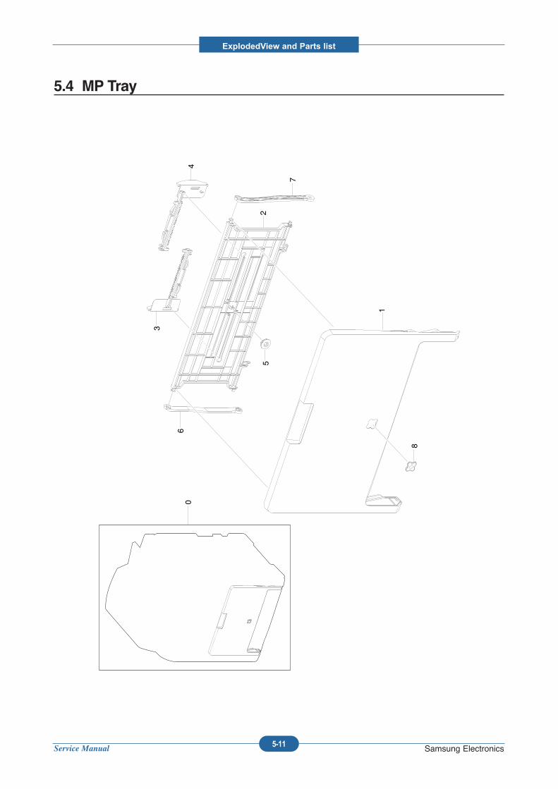
Service Manual
ExplodedView and Parts list
5-11 Samsung Electronics
5.4 MP Tray
0
1
5
6
7
2
3
4
8
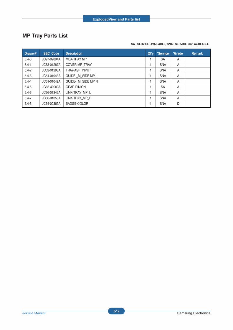
Service Manual
ExplodedView and Parts list
5-12 Samsung Electronics
MP Tray Parts ListSA : SERVICE AVAILABLE, SNA : SERVICE not AVAILABLE
5.4-0 JC97-02894A MEA-TRAY MP 1 SA A
5.4-1 JC63-01287A COVER-MP_TRAY 1 SNA A
5.4-2 JC63-01293A TRAY-ASF_INPUT 1 SNA A
5.4-3 JC61-01043A GUIDE-_M_SIDE MP L 1 SNA A
5.4-4 JC61-01042A GUIDE-_M_SIDE MP R 1 SNA A
5.4-5 JG66-40003A GEAR-PINION 1 SA A
5.4-6 JC66-01349A LINK-TRAY_MP_L 1 SNA A
5.4-7 JC66-01350A LINK-TRAY_MP_R 1 SNA A
5.4-8 JC64-00369A BADGE-COLOR 1 SNA D
Drawer# SEC_Code Description Qt’y *Service *Grade Remark
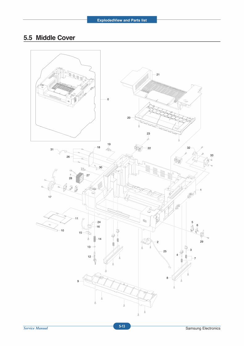
Service Manual
ExplodedView and Parts list
5-13 Samsung Electronics
5.5 Middle Cover
0
21
20
22
23
1918
2728
26
24
16
15
14
13
12
11
10
2
25
98
74
3
29
65
1
17
31
30
32
33
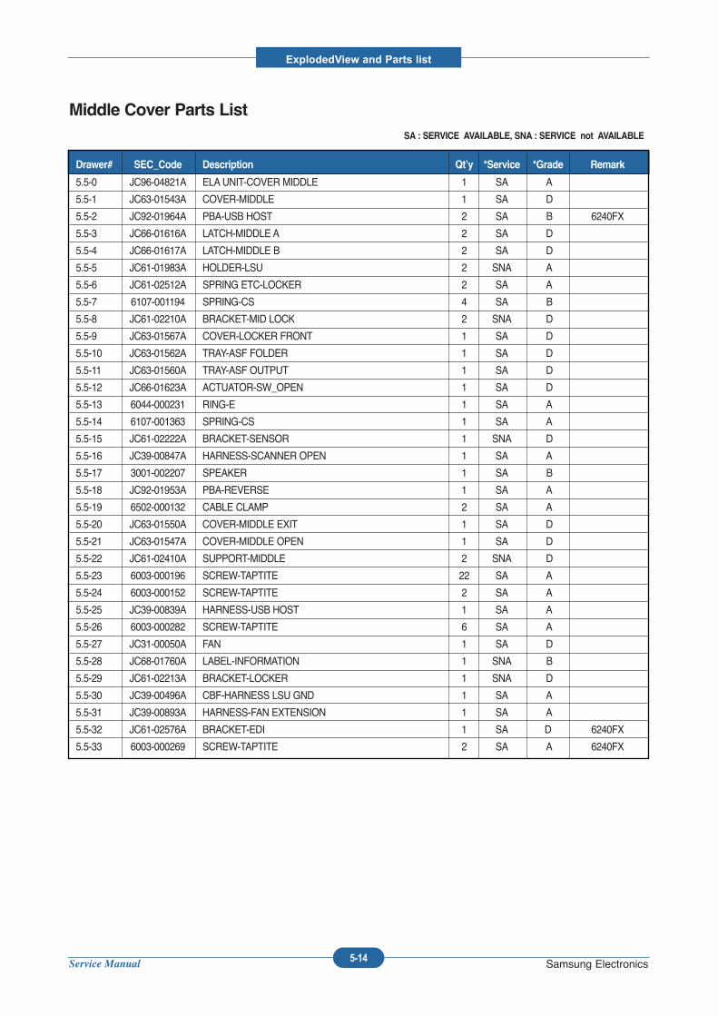
Service Manual
ExplodedView and Parts list
5-14 Samsung Electronics
Middle Cover Parts ListSA : SERVICE AVAILABLE, SNA : SERVICE not AVAILABLE
5.5-0 JC96-04821A ELAUNIT-COVER MIDDLE 1 SA A
5.5-1 JC63-01543A COVER-MIDDLE 1 SA D
5.5-2 JC92-01964A PBA-USB HOST 2 SA B 6240FX
5.5-3 JC66-01616A LATCH-MIDDLE A 2 SA D
5.5-4 JC66-01617A LATCH-MIDDLE B 2 SA D
5.5-5 JC61-01983A HOLDER-LSU 2 SNA A
5.5-6 JC61-02512A SPRING ETC-LOCKER 2 SA A
5.5-7 6107-001194 SPRING-CS 4 SA B
5.5-8 JC61-02210A BRACKET-MID LOCK 2 SNA D
5.5-9 JC63-01567A COVER-LOCKER FRONT 1 SA D
5.5-10 JC63-01562A TRAY-ASF FOLDER 1 SA D
5.5-11 JC63-01560A TRAY-ASF OUTPUT 1 SA D
5.5-12 JC66-01623A ACTUATOR-SW_OPEN 1 SA D
5.5-13 6044-000231 RING-E 1 SA A
5.5-14 6107-001363 SPRING-CS 1 SA A
5.5-15 JC61-02222A BRACKET-SENSOR 1 SNA D
5.5-16 JC39-00847A HARNESS-SCANNER OPEN 1 SA A
5.5-17 3001-002207 SPEAKER 1 SA B
5.5-18 JC92-01953A PBA-REVERSE 1 SA A
5.5-19 6502-000132 CABLE CLAMP 2 SA A
5.5-20 JC63-01550A COVER-MIDDLE EXIT 1 SA D
5.5-21 JC63-01547A COVER-MIDDLE OPEN 1 SA D
5.5-22 JC61-02410A SUPPORT-MIDDLE 2 SNA D
5.5-23 6003-000196 SCREW-TAPTITE 22 SA A
5.5-24 6003-000152 SCREW-TAPTITE 2 SA A
5.5-25 JC39-00839A HARNESS-USB HOST 1 SA A
5.5-26 6003-000282 SCREW-TAPTITE 6 SA A
5.5-27 JC31-00050A FAN 1 SA D
5.5-28 JC68-01760A LABEL-INFORMATION 1 SNA B
5.5-29 JC61-02213A BRACKET-LOCKER 1 SNA D
5.5-30 JC39-00496A CBF-HARNESS LSU GND 1 SA A
5.5-31 JC39-00893A HARNESS-FAN EXTENSION 1 SA A
5.5-32 JC61-02576A BRACKET-EDI 1 SA D 6240FX
5.5-33 6003-000269 SCREW-TAPTITE 2 SA A 6240FX
Drawer# SEC_Code Description Qt’y *Service *Grade Remark
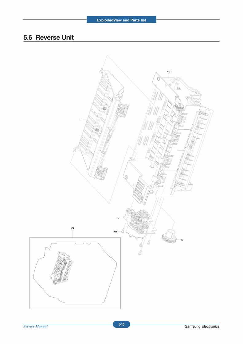
Service Manual
ExplodedView and Parts list
5-15 Samsung Electronics
5.6 Reverse Unit
0
2
1
3
45
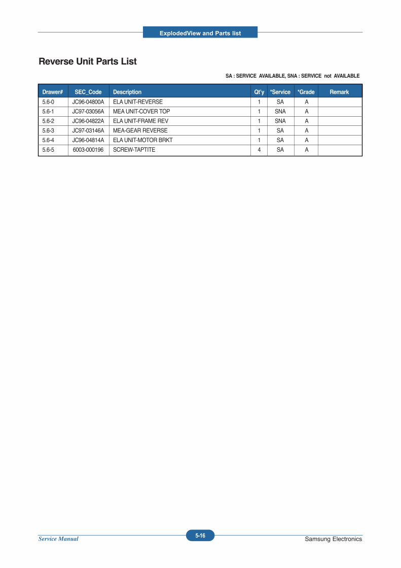
Service Manual
ExplodedView and Parts list
5-16 Samsung Electronics
Reverse Unit Parts ListSA : SERVICE AVAILABLE, SNA : SERVICE not AVAILABLE
5.6-0 JC96-04800A ELAUNIT-REVERSE 1 SA A
5.6-1 JC97-03056A MEAUNIT-COVER TOP 1 SNA A
5.6-2 JC96-04822A ELAUNIT-FRAME REV 1 SNA A
5.6-3 JC97-03146A MEA-GEAR REVERSE 1 SA A
5.6-4 JC96-04814A ELAUNIT-MOTOR BRKT 1 SA A
5.6-5 6003-000196 SCREW-TAPTITE 4 SA A
Drawer# SEC_Code Description Qt’y *Service *Grade Remark
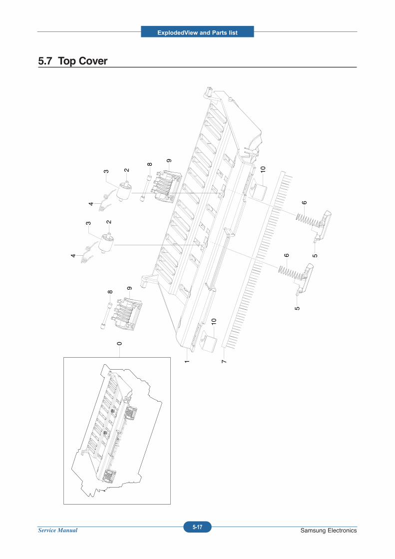
Service Manual
ExplodedView and Parts list
5-17 Samsung Electronics
5.7 Top Cover
10
0
1 7
5
6 5
6
2
4
32
4
3
8
9
8
9
10
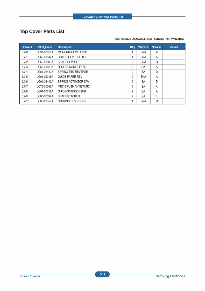
Service Manual
ExplodedView and Parts list
5-18 Samsung Electronics
Top Cover Parts ListSA : SERVICE AVAILABLE, SNA : SERVICE not AVAILABLE
5.7-0 JC97-03056A MEAUNIT-COVER TOP 1 SNA A
5.7-1 JC63-01542A COVER-REVERSE TOP 1 SNA A
5.7-2 JC66-01833A SHAFT-REV IDLE 2 SNA D
5.7-3 JC66-00529A ROLLER-M-IDLE FEED 2 SA A
5.7-4 JC61-02449A SPRING ETC-REVERSE 2 SA D
5.7-5 JC61-02218A GUIDE-PAPER REV 2 SNA A
5.7-6 JC61-02449A SPRING ACTUATOR S/W 2 SA D
5.7-7 JC75-00095A MEC-BRUSH ANTISTATIC 1 SA A
5.7-8 JC61-00712A GUIDE-STACKER SUB 2 SA A
5.7-9 JC66-00594A SHAFT-STACKER 2 SA D
5.7-10 JC63-01557A GROUND REV FRONT 1 SNA D
Drawer# SEC_Code Description Qt’y *Service *Grade Remark
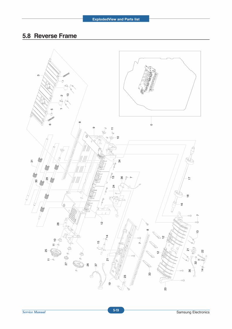
Service Manual
ExplodedView and Parts list
5-19 Samsung Electronics
5.8 Reverse Frame
0
7
16
1817
13
21
32
221436
2012
12
33
36
37
23
7
8
2119
15
14
2413
10
11
7
9
8
34
122810
11
1125
27 26
12 13
56
3
29
30
31
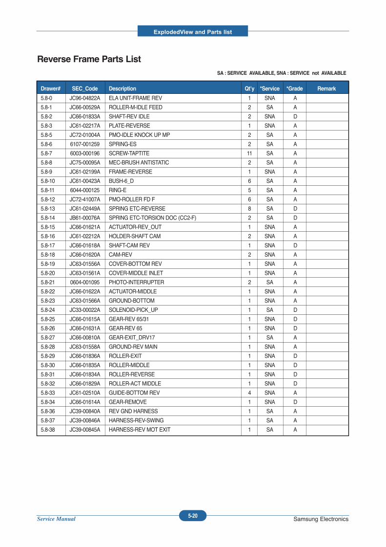
Service Manual
ExplodedView and Parts list
5-20 Samsung Electronics
Reverse Frame Parts ListSA : SERVICE AVAILABLE, SNA : SERVICE not AVAILABLE
5.8-0 JC96-04822A ELAUNIT-FRAME REV 1 SNA A
5.8-1 JC66-00529A ROLLER-M-IDLE FEED 2 SA A
5.8-2 JC66-01833A SHAFT-REV IDLE 2 SNA D
5.8-3 JC61-02217A PLATE-REVERSE 1 SNA A
5.8-5 JC72-01004A PMO-IDLE KNOCK UP MP 2 SA A
5.8-6 6107-001259 SPRING-ES 2 SA A
5.8-7 6003-000196 SCREW-TAPTITE 11 SA A
5.8-8 JC75-00095A MEC-BRUSH ANTISTATIC 2 SA A
5.8-9 JC61-02199A FRAME-REVERSE 1 SNA A
5.8-10 JC61-00423A BUSH-6_D 6 SA A
5.8-11 6044-000125 RING-E 5 SA A
5.8-12 JC72-41007A PMO-ROLLER FD F 6 SA A
5.8-13 JC61-02449A SPRING ETC-REVERSE 8 SA D
5.8-14 JB61-00076A SPRING ETC-TORSION DOC (CC2-F) 2 SA D
5.8-15 JC66-01621A ACTUATOR-REV_OUT 1 SNA A
5.8-16 JC61-02212A HOLDER-SHAFT CAM 2 SNA A
5.8-17 JC66-01618A SHAFT-CAM REV 1 SNA D
5.8-18 JC66-01620A CAM-REV 2 SNA A
5.8-19 JC63-01556A COVER-BOTTOM REV 1 SNA A
5.8-20 JC63-01561A COVER-MIDDLE INLET 1 SNA A
5.8-21 0604-001095 PHOTO-INTERRUPTER 2 SA A
5.8-22 JC66-01622A ACTUATOR-MIDDLE 1 SNA A
5.8-23 JC63-01566A GROUND-BOTTOM 1 SNA A
5.8-24 JC33-00022A SOLENOID-PICK_UP 1 SA D
5.8-25 JC66-01615A GEAR-REV 65/31 1 SNA D
5.8-26 JC66-01631A GEAR-REV 65 1 SNA D
5.8-27 JC66-00810A GEAR-EXIT_DRV17 1 SA A
5.8-28 JC63-01558A GROUND-REV MAIN 1 SNA A
5.8-29 JC66-01836A ROLLER-EXIT 1 SNA D
5.8-30 JC66-01835A ROLLER-MIDDLE 1 SNA D
5.8-31 JC66-01834A ROLLER-REVERSE 1 SNA D
5.8-32 JC66-01829A ROLLER-ACT MIDDLE 1 SNA D
5.8-33 JC61-02510A GUIDE-BOTTOM REV 4 SNA A
5.8-34 JC66-01614A GEAR-REMOVE 1 SNA D
5.8-36 JC39-00840A REV GND HARNESS 1 SA A
5.8-37 JC39-00846A HARNESS-REV-SWING 1 SA A
5.8-38 JC39-00845A HARNESS-REV MOT EXIT 1 SA A
Drawer# SEC_Code Description Qt’y *Service *Grade Remark
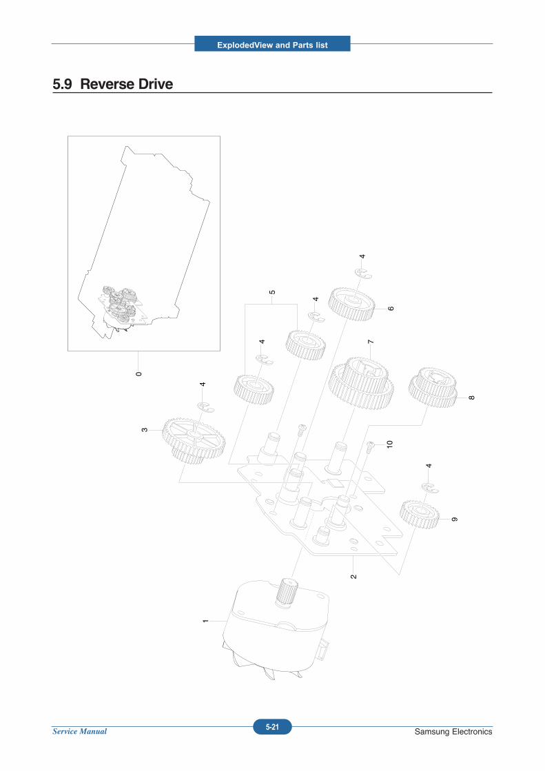
Service Manual
ExplodedView and Parts list
5-21 Samsung Electronics
5.9 Reverse Drive
0
1
2
3
4
4
4
4
4
5
6
7
8
9
10
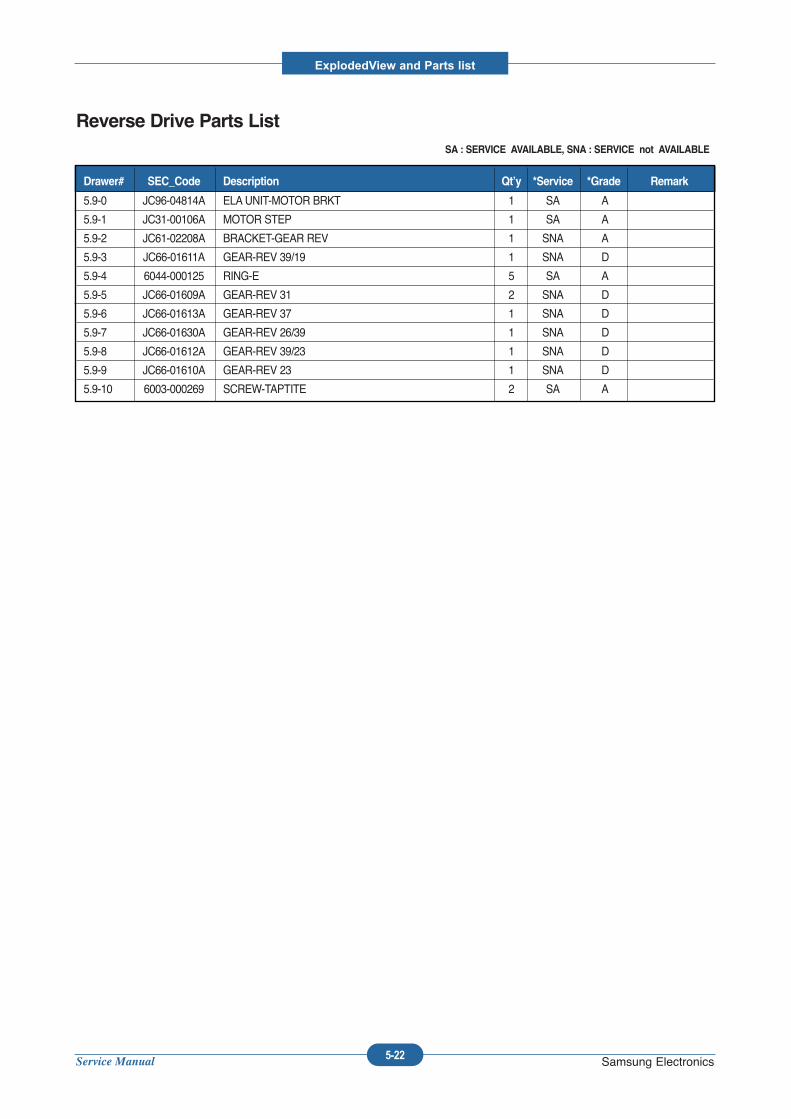
Service Manual
ExplodedView and Parts list
5-22 Samsung Electronics
Reverse Drive Parts ListSA : SERVICE AVAILABLE, SNA : SERVICE not AVAILABLE
5.9-0 JC96-04814A ELAUNIT-MOTOR BRKT 1 SA A
5.9-1 JC31-00106A MOTOR STEP 1 SA A
5.9-2 JC61-02208A BRACKET-GEAR REV 1 SNA A
5.9-3 JC66-01611A GEAR-REV 39/19 1 SNA D
5.9-4 6044-000125 RING-E 5 SA A
5.9-5 JC66-01609A GEAR-REV 31 2 SNA D
5.9-6 JC66-01613A GEAR-REV 37 1 SNA D
5.9-7 JC66-01630A GEAR-REV 26/39 1 SNA D
5.9-8 JC66-01612A GEAR-REV 39/23 1 SNA D
5.9-9 JC66-01610A GEAR-REV 23 1 SNA D
5.9-10 6003-000269 SCREW-TAPTITE 2 SA A
Drawer# SEC_Code Description Qt’y *Service *Grade Remark

Service Manual
ExplodedView and Parts list
5-23 Samsung Electronics
5.10 Frame
3
0
15
28
19
6
98 7
11
10
1214
13
18
4
5
2
16
17
1
27
20
5
21
22
23
24
25
26
27
20
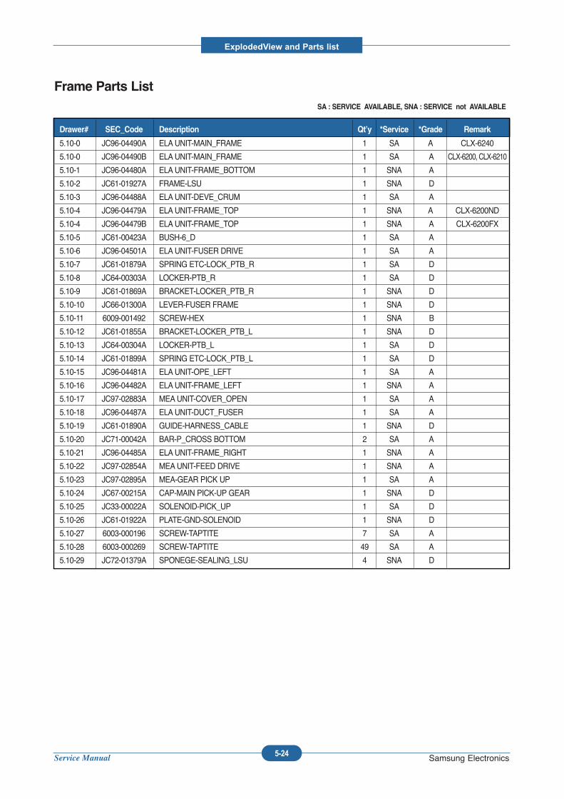
Service Manual
ExplodedView and Parts list
5-24 Samsung Electronics
Frame Parts ListSA : SERVICE AVAILABLE, SNA : SERVICE not AVAILABLE
5.10-0 JC96-04490A ELAUNIT-MAIN_FRAME 1 SA A CLX-6240
5.10-0 JC96-04490B ELAUNIT-MAIN_FRAME 1 SA A CLX-6200, CLX-6210
5.10-1 JC96-04480A ELAUNIT-FRAME_BOTTOM 1 SNA A
5.10-2 JC61-01927A FRAME-LSU 1 SNA D
5.10-3 JC96-04488A ELAUNIT-DEVE_CRUM 1 SA A
5.10-4 JC96-04479A ELAUNIT-FRAME_TOP 1 SNA A CLX-6200ND
5.10-4 JC96-04479B ELAUNIT-FRAME_TOP 1 SNA A CLX-6200FX
5.10-5 JC61-00423A BUSH-6_D 1 SA A
5.10-6 JC96-04501A ELAUNIT-FUSER DRIVE 1 SA A
5.10-7 JC61-01879A SPRING ETC-LOCK_PTB_R 1 SA D
5.10-8 JC64-00303A LOCKER-PTB_R 1 SA D
5.10-9 JC61-01869A BRACKET-LOCKER_PTB_R 1 SNA D
5.10-10 JC66-01300A LEVER-FUSER FRAME 1 SNA D
5.10-11 6009-001492 SCREW-HEX 1 SNA B
5.10-12 JC61-01855A BRACKET-LOCKER_PTB_L 1 SNA D
5.10-13 JC64-00304A LOCKER-PTB_L 1 SA D
5.10-14 JC61-01899A SPRING ETC-LOCK_PTB_L 1 SA D
5.10-15 JC96-04481A ELAUNIT-OPE_LEFT 1 SA A
5.10-16 JC96-04482A ELAUNIT-FRAME_LEFT 1 SNA A
5.10-17 JC97-02883A MEAUNIT-COVER_OPEN 1 SA A
5.10-18 JC96-04487A ELAUNIT-DUCT_FUSER 1 SA A
5.10-19 JC61-01890A GUIDE-HARNESS_CABLE 1 SNA D
5.10-20 JC71-00042A BAR-P_CROSS BOTTOM 2 SA A
5.10-21 JC96-04485A ELAUNIT-FRAME_RIGHT 1 SNA A
5.10-22 JC97-02854A MEAUNIT-FEED DRIVE 1 SNA A
5.10-23 JC97-02895A MEA-GEAR PICK UP 1 SA A
5.10-24 JC67-00215A CAP-MAIN PICK-UP GEAR 1 SNA D
5.10-25 JC33-00022A SOLENOID-PICK_UP 1 SA D
5.10-26 JC61-01922A PLATE-GND-SOLENOID 1 SNA D
5.10-27 6003-000196 SCREW-TAPTITE 7 SA A
5.10-28 6003-000269 SCREW-TAPTITE 49 SA A
5.10-29 JC72-01379A SPONEGE-SEALING_LSU 4 SNA D
Drawer# SEC_Code Description Qt’y *Service *Grade Remark
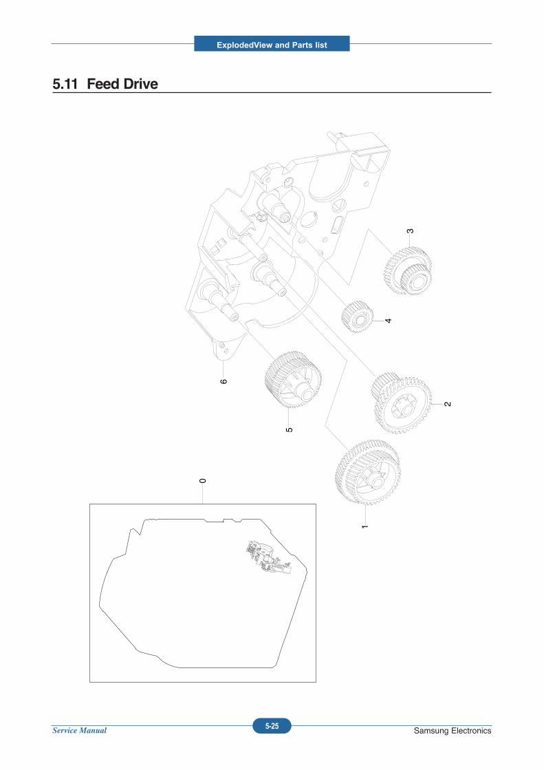
Service Manual
ExplodedView and Parts list
5-25 Samsung Electronics
5.11 Feed Drive
0
6
5
1
2
3
4
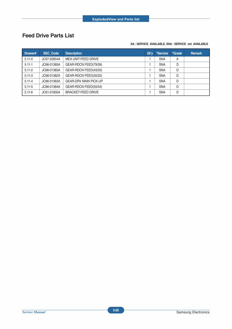
Service Manual
ExplodedView and Parts list
5-26 Samsung Electronics
Feed Drive Parts ListSA : SERVICE AVAILABLE, SNA : SERVICE not AVAILABLE
5.11-0 JC97-02854A MEAUNIT-FEED DRIVE 1 SNA A
5.11-1 JC66-01385A GEAR-RDCN FEED(79/39) 1 SNA D
5.11-2 JC66-01383A GEAR-RDCN FEED(43/23) 1 SNA D
5.11-3 JC66-01382A GEAR-RDCN FEED(35/22) 1 SNA D
5.11-4 JC66-01363A GEAR-DRV MAIN PICK-UP 1 SNA D
5.11-5 JC66-01384A GEAR-RDCN FEED(55/54) 1 SNA D
5.11-6 JC61-01835A BRACKET-FEED DRIVE 1 SNA D
Drawer# SEC_Code Description Qt’y *Service *Grade Remark
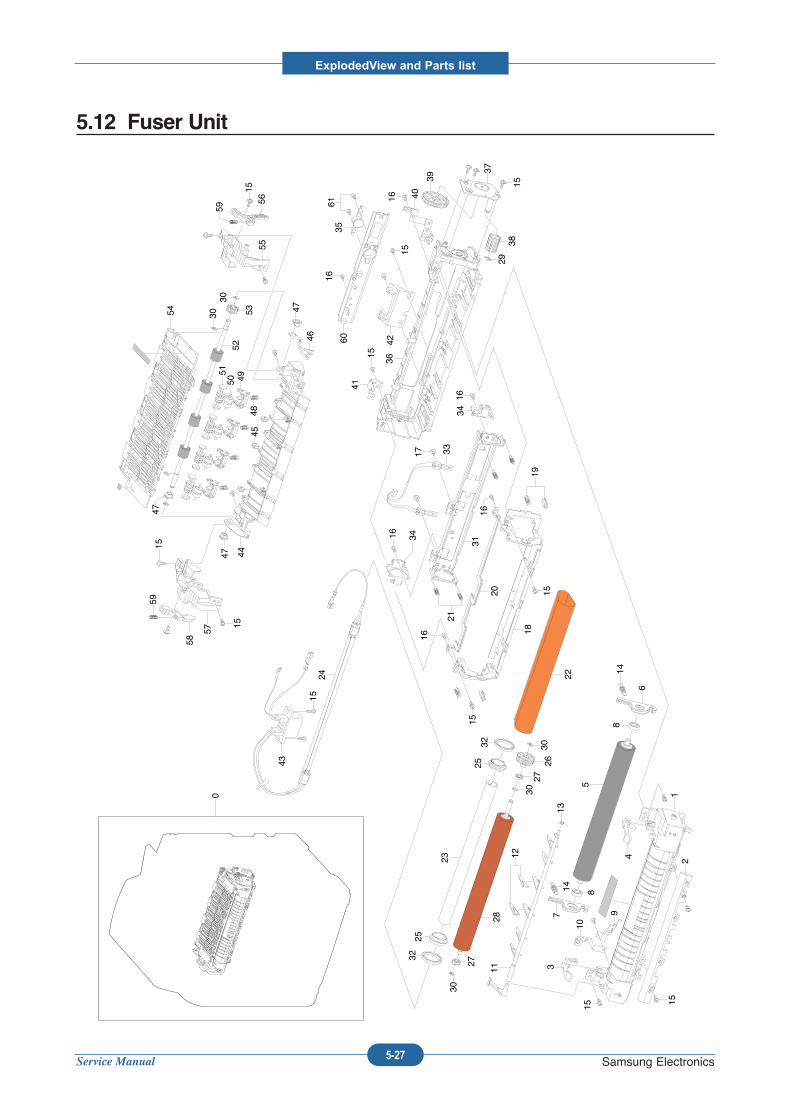
Service Manual
ExplodedView and Parts list
5-27 Samsung Electronics
5.12 Fuser Unit
0
152
1
15
3
4
9
10
7
6
148
814
5
13
12
1128
30
27
2730
3026
22
3225
2532
24
23
43
1918
20 15
15
16
16
21
31
3416
3416
3317
36
41
15
42
1540
39
37
1538
29
15
16
3561
16
60
5615
59
55
54 3030
53
5150 49
4845
52
47
47
5915
57
58
1544
47
46
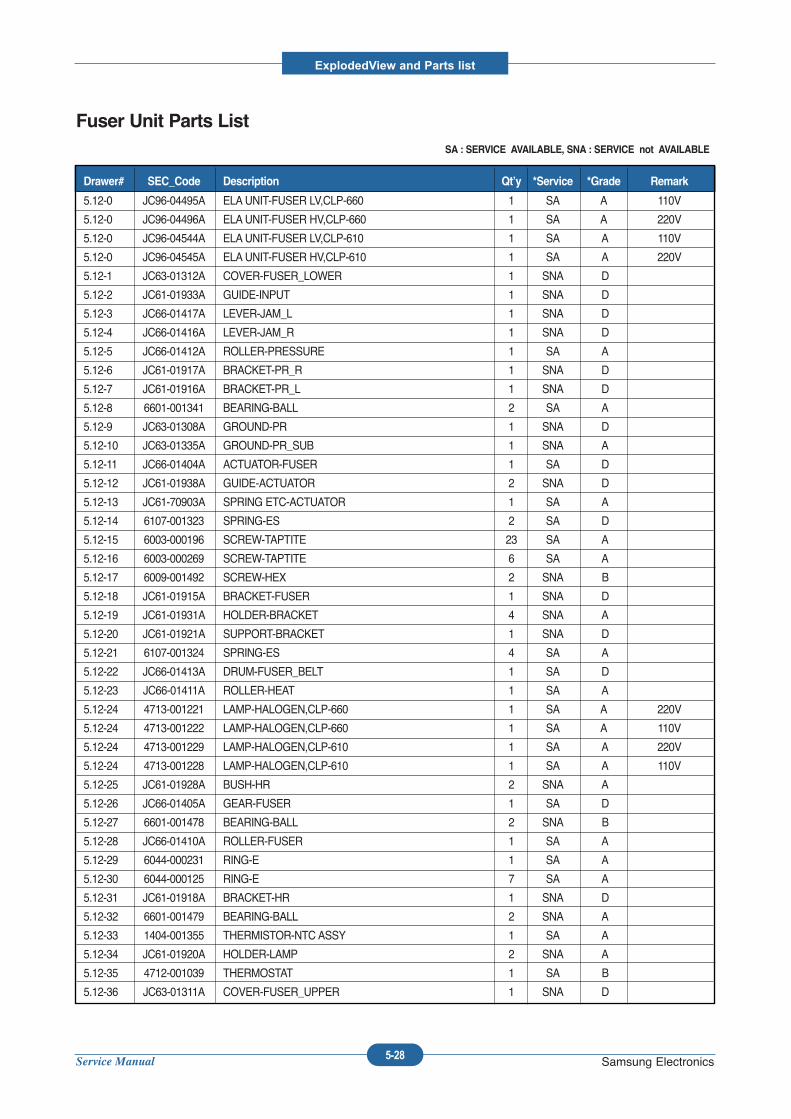
Service Manual
ExplodedView and Parts list
5-28 Samsung Electronics
Fuser Unit Parts ListSA : SERVICE AVAILABLE, SNA : SERVICE not AVAILABLE
5.12-0 JC96-04495A ELAUNIT-FUSER LV,CLP-660 1 SA A 110V
5.12-0 JC96-04496A ELAUNIT-FUSER HV,CLP-660 1 SA A 220V
5.12-0 JC96-04544A ELAUNIT-FUSER LV,CLP-610 1 SA A 110V
5.12-0 JC96-04545A ELAUNIT-FUSER HV,CLP-610 1 SA A 220V
5.12-1 JC63-01312A COVER-FUSER_LOWER 1 SNA D
5.12-2 JC61-01933A GUIDE-INPUT 1 SNA D
5.12-3 JC66-01417A LEVER-JAM_L 1 SNA D
5.12-4 JC66-01416A LEVER-JAM_R 1 SNA D
5.12-5 JC66-01412A ROLLER-PRESSURE 1 SA A
5.12-6 JC61-01917A BRACKET-PR_R 1 SNA D
5.12-7 JC61-01916A BRACKET-PR_L 1 SNA D
5.12-8 6601-001341 BEARING-BALL 2 SA A
5.12-9 JC63-01308A GROUND-PR 1 SNA D
5.12-10 JC63-01335A GROUND-PR_SUB 1 SNA A
5.12-11 JC66-01404A ACTUATOR-FUSER 1 SA D
5.12-12 JC61-01938A GUIDE-ACTUATOR 2 SNA D
5.12-13 JC61-70903A SPRING ETC-ACTUATOR 1 SA A
5.12-14 6107-001323 SPRING-ES 2 SA D
5.12-15 6003-000196 SCREW-TAPTITE 23 SA A
5.12-16 6003-000269 SCREW-TAPTITE 6 SA A
5.12-17 6009-001492 SCREW-HEX 2 SNA B
5.12-18 JC61-01915A BRACKET-FUSER 1 SNA D
5.12-19 JC61-01931A HOLDER-BRACKET 4 SNA A
5.12-20 JC61-01921A SUPPORT-BRACKET 1 SNA D
5.12-21 6107-001324 SPRING-ES 4 SA A
5.12-22 JC66-01413A DRUM-FUSER_BELT 1 SA D
5.12-23 JC66-01411A ROLLER-HEAT 1 SA A
5.12-24 4713-001221 LAMP-HALOGEN,CLP-660 1 SA A 220V
5.12-24 4713-001222 LAMP-HALOGEN,CLP-660 1 SA A 110V
5.12-24 4713-001229 LAMP-HALOGEN,CLP-610 1 SA A 220V
5.12-24 4713-001228 LAMP-HALOGEN,CLP-610 1 SA A 110V
5.12-25 JC61-01928A BUSH-HR 2 SNA A
5.12-26 JC66-01405A GEAR-FUSER 1 SA D
5.12-27 6601-001478 BEARING-BALL 2 SNA B
5.12-28 JC66-01410A ROLLER-FUSER 1 SA A
5.12-29 6044-000231 RING-E 1 SA A
5.12-30 6044-000125 RING-E 7 SA A
5.12-31 JC61-01918A BRACKET-HR 1 SNA D
5.12-32 6601-001479 BEARING-BALL 2 SNA A
5.12-33 1404-001355 THERMISTOR-NTC ASSY 1 SA A
5.12-34 JC61-01920A HOLDER-LAMP 2 SNA A
5.12-35 4712-001039 THERMOSTAT 1 SA B
5.12-36 JC63-01311A COVER-FUSER_UPPER 1 SNA D
Drawer# SEC_Code Description Qt’y *Service *Grade Remark
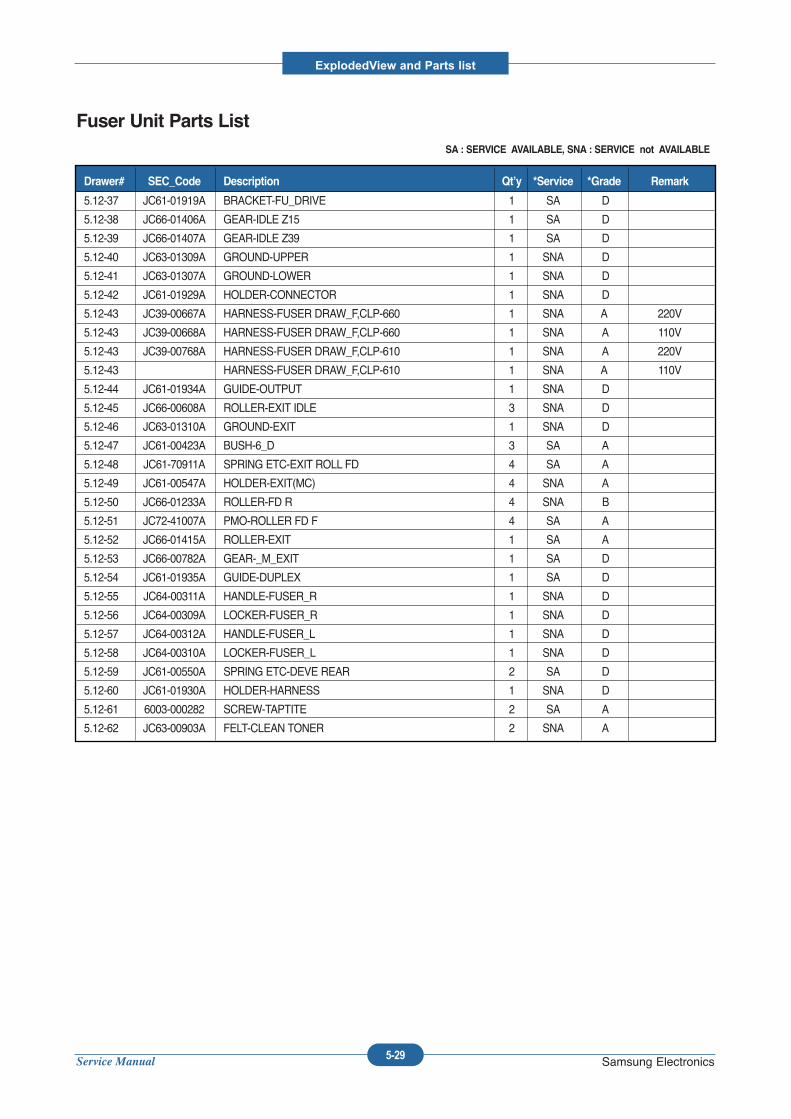
Service Manual
ExplodedView and Parts list
5-29 Samsung Electronics
Fuser Unit Parts ListSA : SERVICE AVAILABLE, SNA : SERVICE not AVAILABLE
5.12-37 JC61-01919A BRACKET-FU_DRIVE 1 SA D
5.12-38 JC66-01406A GEAR-IDLE Z15 1 SA D
5.12-39 JC66-01407A GEAR-IDLE Z39 1 SA D
5.12-40 JC63-01309A GROUND-UPPER 1 SNA D
5.12-41 JC63-01307A GROUND-LOWER 1 SNA D
5.12-42 JC61-01929A HOLDER-CONNECTOR 1 SNA D
5.12-43 JC39-00667A HARNESS-FUSER DRAW_F,CLP-660 1 SNA A 220V
5.12-43 JC39-00668A HARNESS-FUSER DRAW_F,CLP-660 1 SNA A 110V
5.12-43 JC39-00768A HARNESS-FUSER DRAW_F,CLP-610 1 SNA A 220V
5.12-43 HARNESS-FUSER DRAW_F,CLP-610 1 SNA A 110V
5.12-44 JC61-01934A GUIDE-OUTPUT 1 SNA D
5.12-45 JC66-00608A ROLLER-EXIT IDLE 3 SNA D
5.12-46 JC63-01310A GROUND-EXIT 1 SNA D
5.12-47 JC61-00423A BUSH-6_D 3 SA A
5.12-48 JC61-70911A SPRING ETC-EXIT ROLL FD 4 SA A
5.12-49 JC61-00547A HOLDER-EXIT(MC) 4 SNA A
5.12-50 JC66-01233A ROLLER-FD R 4 SNA B
5.12-51 JC72-41007A PMO-ROLLER FD F 4 SA A
5.12-52 JC66-01415A ROLLER-EXIT 1 SA A
5.12-53 JC66-00782A GEAR-_M_EXIT 1 SA D
5.12-54 JC61-01935A GUIDE-DUPLEX 1 SA D
5.12-55 JC64-00311A HANDLE-FUSER_R 1 SNA D
5.12-56 JC64-00309A LOCKER-FUSER_R 1 SNA D
5.12-57 JC64-00312A HANDLE-FUSER_L 1 SNA D
5.12-58 JC64-00310A LOCKER-FUSER_L 1 SNA D
5.12-59 JC61-00550A SPRING ETC-DEVE REAR 2 SA D
5.12-60 JC61-01930A HOLDER-HARNESS 1 SNA D
5.12-61 6003-000282 SCREW-TAPTITE 2 SA A
5.12-62 JC63-00903A FELT-CLEAN TONER 2 SNA A
Drawer# SEC_Code Description Qt’y *Service *Grade Remark
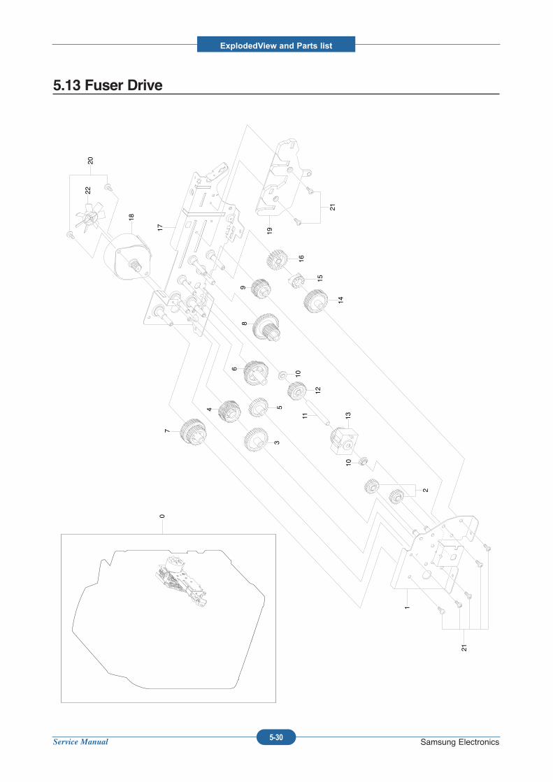
Service Manual
ExplodedView and Parts list
5-30 Samsung Electronics
5.13 Fuser Drive
0
1
21
2
10
10
12
11 1314
15
16
19
21
2220
18
177
3
4 5
6
89
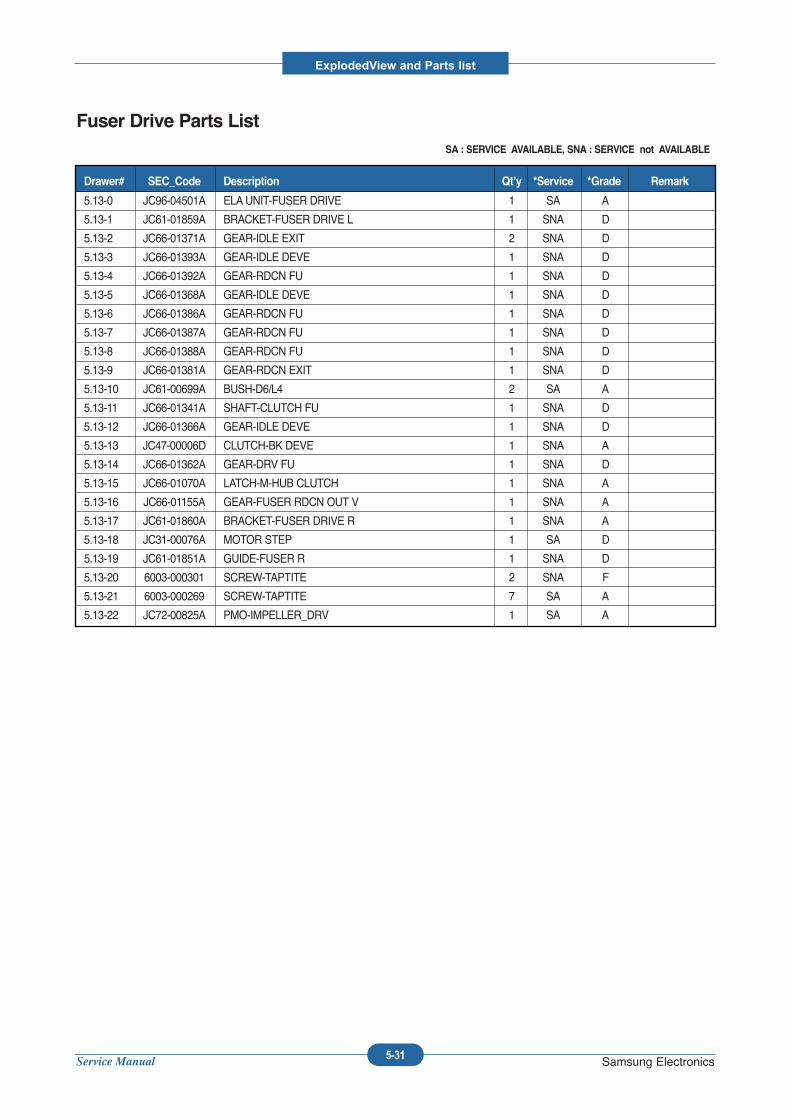
Service Manual
ExplodedView and Parts list
5-31 Samsung Electronics
Fuser Drive Parts ListSA : SERVICE AVAILABLE, SNA : SERVICE not AVAILABLE
5.13-0 JC96-04501A ELAUNIT-FUSER DRIVE 1 SA A
5.13-1 JC61-01859A BRACKET-FUSER DRIVE L 1 SNA D
5.13-2 JC66-01371A GEAR-IDLE EXIT 2 SNA D
5.13-3 JC66-01393A GEAR-IDLE DEVE 1 SNA D
5.13-4 JC66-01392A GEAR-RDCN FU 1 SNA D
5.13-5 JC66-01368A GEAR-IDLE DEVE 1 SNA D
5.13-6 JC66-01386A GEAR-RDCN FU 1 SNA D
5.13-7 JC66-01387A GEAR-RDCN FU 1 SNA D
5.13-8 JC66-01388A GEAR-RDCN FU 1 SNA D
5.13-9 JC66-01381A GEAR-RDCN EXIT 1 SNA D
5.13-10 JC61-00699A BUSH-D6/L4 2 SA A
5.13-11 JC66-01341A SHAFT-CLUTCH FU 1 SNA D
5.13-12 JC66-01366A GEAR-IDLE DEVE 1 SNA D
5.13-13 JC47-00006D CLUTCH-BK DEVE 1 SNA A
5.13-14 JC66-01362A GEAR-DRV FU 1 SNA D
5.13-15 JC66-01070A LATCH-M-HUB CLUTCH 1 SNA A
5.13-16 JC66-01155A GEAR-FUSER RDCN OUT V 1 SNA A
5.13-17 JC61-01860A BRACKET-FUSER DRIVE R 1 SNA A
5.13-18 JC31-00076A MOTOR STEP 1 SA D
5.13-19 JC61-01851A GUIDE-FUSER R 1 SNA D
5.13-20 6003-000301 SCREW-TAPTITE 2 SNA F
5.13-21 6003-000269 SCREW-TAPTITE 7 SA A
5.13-22 JC72-00825A PMO-IMPELLER_DRV 1 SA A
Drawer# SEC_Code Description Qt’y *Service *Grade Remark
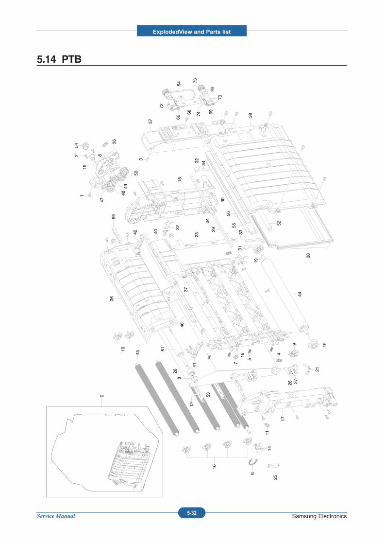
Service Manual
ExplodedView and Parts list
5-32 Samsung Electronics
5.14 PTB
30
0
45
10
10
6
2514
12 8
54
15
35
50
47
4849
1822
24
57
3
54
69
70
76
7368 74
72
66 39
38
52
33
29
31
32 34
5556
19
449
21
26 27
17
19
5
16
41
208
51
4637
40
36
53
23
4
59
11
12
42
7
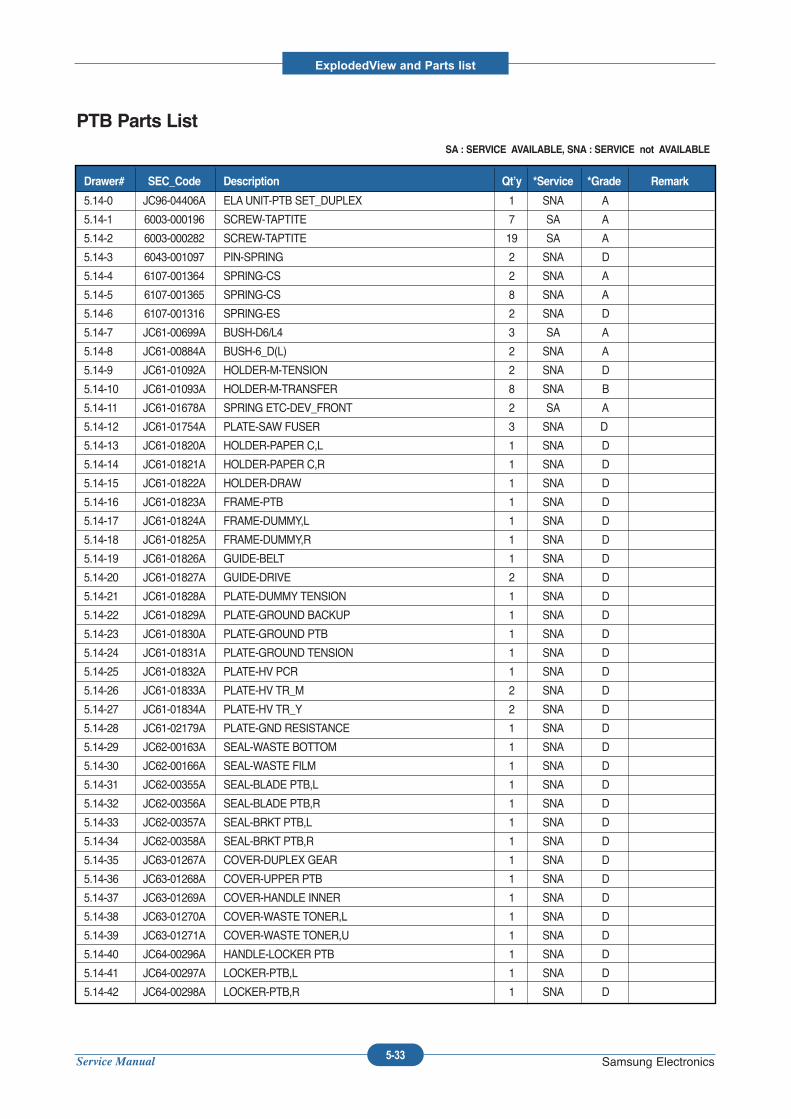
Service Manual
ExplodedView and Parts list
5-33 Samsung Electronics
PTB Parts ListSA : SERVICE AVAILABLE, SNA : SERVICE not AVAILABLE
5.14-0 JC96-04406A ELAUNIT-PTB SET_DUPLEX 1 SNA A
5.14-1 6003-000196 SCREW-TAPTITE 7 SA A
5.14-2 6003-000282 SCREW-TAPTITE 19 SA A
5.14-3 6043-001097 PIN-SPRING 2 SNA D
5.14-4 6107-001364 SPRING-CS 2 SNA A
5.14-5 6107-001365 SPRING-CS 8 SNA A
5.14-6 6107-001316 SPRING-ES 2 SNA D
5.14-7 JC61-00699A BUSH-D6/L4 3 SA A
5.14-8 JC61-00884A BUSH-6_D(L) 2 SNA A
5.14-9 JC61-01092A HOLDER-M-TENSION 2 SNA D
5.14-10 JC61-01093A HOLDER-M-TRANSFER 8 SNA B
5.14-11 JC61-01678A SPRING ETC-DEV_FRONT 2 SA A
5.14-12 JC61-01754A PLATE-SAW FUSER 3 SNA D
5.14-13 JC61-01820A HOLDER-PAPER C,L 1 SNA D
5.14-14 JC61-01821A HOLDER-PAPER C,R 1 SNA D
5.14-15 JC61-01822A HOLDER-DRAW 1 SNA D
5.14-16 JC61-01823A FRAME-PTB 1 SNA D
5.14-17 JC61-01824A FRAME-DUMMY,L 1 SNA D
5.14-18 JC61-01825A FRAME-DUMMY,R 1 SNA D
5.14-19 JC61-01826A GUIDE-BELT 1 SNA D
5.14-20 JC61-01827A GUIDE-DRIVE 2 SNA D
5.14-21 JC61-01828A PLATE-DUMMY TENSION 1 SNA D
5.14-22 JC61-01829A PLATE-GROUND BACKUP 1 SNA D
5.14-23 JC61-01830A PLATE-GROUND PTB 1 SNA D
5.14-24 JC61-01831A PLATE-GROUND TENSION 1 SNA D
5.14-25 JC61-01832A PLATE-HV PCR 1 SNA D
5.14-26 JC61-01833A PLATE-HV TR_M 2 SNA D
5.14-27 JC61-01834A PLATE-HV TR_Y 2 SNA D
5.14-28 JC61-02179A PLATE-GND RESISTANCE 1 SNA D
5.14-29 JC62-00163A SEAL-WASTE BOTTOM 1 SNA D
5.14-30 JC62-00166A SEAL-WASTE FILM 1 SNA D
5.14-31 JC62-00355A SEAL-BLADE PTB,L 1 SNA D
5.14-32 JC62-00356A SEAL-BLADE PTB,R 1 SNA D
5.14-33 JC62-00357A SEAL-BRKT PTB,L 1 SNA D
5.14-34 JC62-00358A SEAL-BRKT PTB,R 1 SNA D
5.14-35 JC63-01267A COVER-DUPLEX GEAR 1 SNA D
5.14-36 JC63-01268A COVER-UPPER PTB 1 SNA D
5.14-37 JC63-01269A COVER-HANDLE INNER 1 SNA D
5.14-38 JC63-01270A COVER-WASTE TONER,L 1 SNA D
5.14-39 JC63-01271A COVER-WASTE TONER,U 1 SNA D
5.14-40 JC64-00296A HANDLE-LOCKER PTB 1 SNA D
5.14-41 JC64-00297A LOCKER-PTB,L 1 SNA D
5.14-42 JC64-00298A LOCKER-PTB,R 1 SNA D
Drawer# SEC_Code Description Qt’y *Service *Grade Remark
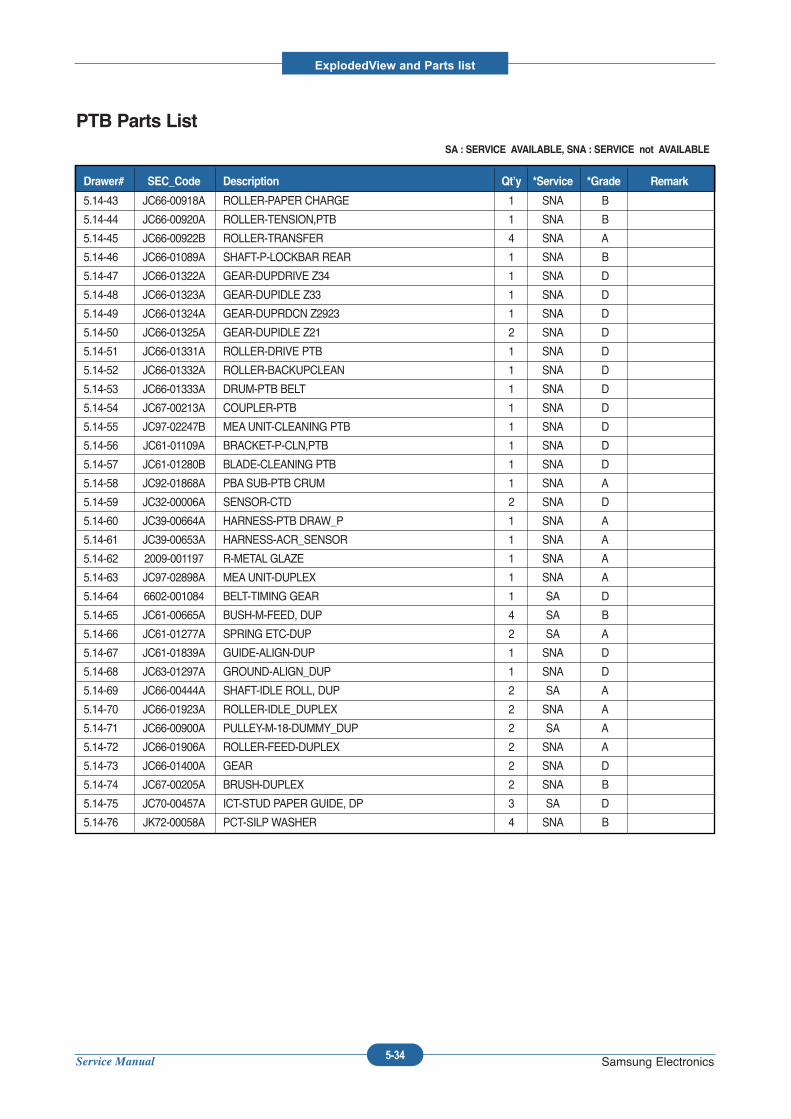
Service Manual
ExplodedView and Parts list
5-34 Samsung Electronics
PTB Parts ListSA : SERVICE AVAILABLE, SNA : SERVICE not AVAILABLE
5.14-43 JC66-00918A ROLLER-PAPER CHARGE 1 SNA B
5.14-44 JC66-00920A ROLLER-TENSION,PTB 1 SNA B
5.14-45 JC66-00922B ROLLER-TRANSFER 4 SNA A
5.14-46 JC66-01089A SHAFT-P-LOCKBAR REAR 1 SNA B
5.14-47 JC66-01322A GEAR-DUPDRIVE Z34 1 SNA D
5.14-48 JC66-01323A GEAR-DUPIDLE Z33 1 SNA D
5.14-49 JC66-01324A GEAR-DUPRDCN Z2923 1 SNA D
5.14-50 JC66-01325A GEAR-DUPIDLE Z21 2 SNA D
5.14-51 JC66-01331A ROLLER-DRIVE PTB 1 SNA D
5.14-52 JC66-01332A ROLLER-BACKUPCLEAN 1 SNA D
5.14-53 JC66-01333A DRUM-PTB BELT 1 SNA D
5.14-54 JC67-00213A COUPLER-PTB 1 SNA D
5.14-55 JC97-02247B MEAUNIT-CLEANING PTB 1 SNA D
5.14-56 JC61-01109A BRACKET-P-CLN,PTB 1 SNA D
5.14-57 JC61-01280B BLADE-CLEANING PTB 1 SNA D
5.14-58 JC92-01868A PBASUB-PTB CRUM 1 SNA A
5.14-59 JC32-00006A SENSOR-CTD 2 SNA D
5.14-60 JC39-00664A HARNESS-PTB DRAW_P 1 SNA A
5.14-61 JC39-00653A HARNESS-ACR_SENSOR 1 SNA A
5.14-62 2009-001197 R-METAL GLAZE 1 SNA A
5.14-63 JC97-02898A MEAUNIT-DUPLEX 1 SNA A
5.14-64 6602-001084 BELT-TIMING GEAR 1 SA D
5.14-65 JC61-00665A BUSH-M-FEED, DUP 4 SA B
5.14-66 JC61-01277A SPRING ETC-DUP 2 SA A
5.14-67 JC61-01839A GUIDE-ALIGN-DUP 1 SNA D
5.14-68 JC63-01297A GROUND-ALIGN_DUP 1 SNA D
5.14-69 JC66-00444A SHAFT-IDLE ROLL, DUP 2 SA A
5.14-70 JC66-01923A ROLLER-IDLE_DUPLEX 2 SNA A
5.14-71 JC66-00900A PULLEY-M-18-DUMMY_DUP 2 SA A
5.14-72 JC66-01906A ROLLER-FEED-DUPLEX 2 SNA A
5.14-73 JC66-01400A GEAR 2 SNA D
5.14-74 JC67-00205A BRUSH-DUPLEX 2 SNA B
5.14-75 JC70-00457A ICT-STUD PAPER GUIDE, DP 3 SA D
5.14-76 JK72-00058A PCT-SILP WASHER 4 SNA B
Drawer# SEC_Code Description Qt’y *Service *Grade Remark
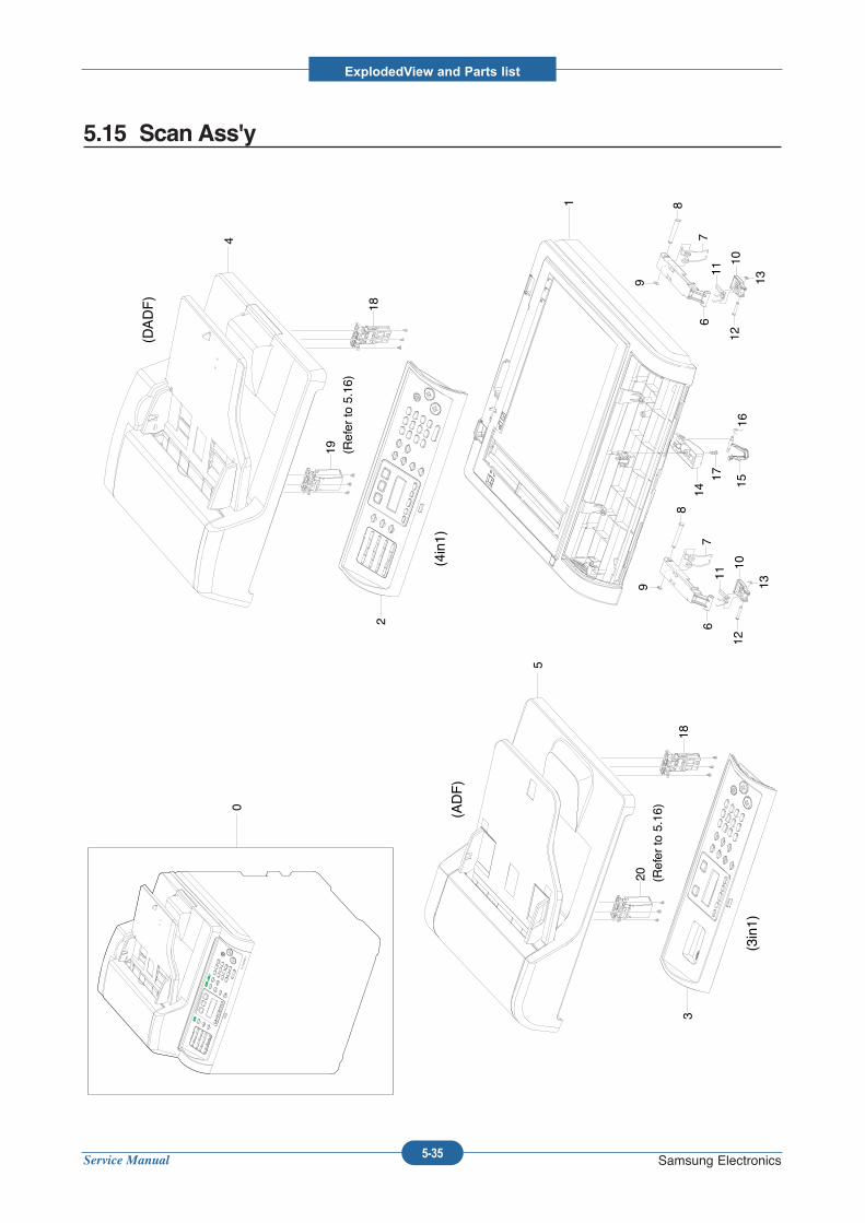
Service Manual
ExplodedView and Parts list
5-35 Samsung Electronics
5.15 Scan Ass'y
0
1
2
3
4
5
67
8
9
10
11
12
13
67
8
9
10
11
12
13
14
1516
17
(ADF)
(4in1)
(3in1)
18
19
18
20
(DADF)
(Refer to 5.16)
(Refer to 5.16)
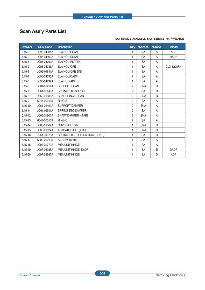
Service Manual
ExplodedView and Parts list
5-36 Samsung Electronics
Scan Ass'y Parts ListSA : SERVICE AVAILABLE, SNA : SERVICE not AVAILABLE
5.15-0 JC96-04901A ELAHOU-SCAN 1 SA A ADF
5.15-0 JC96-04900A ELAHOU-SCAN 1 SA A DADF
5.15-1 JC96-04793A ELAHOU-PLATEN 1 SA A
5.15-2 JC96-04786A ELAHOU-OPE 1 SA A CLX-6200FX
5.15-3 JC96-04811A ELAHOU-OPE 3IN1 1 SA A
5.15-4 JC96-04790A ELAHOU-DADF 1 SA A
5.15-5 JC96-04792A ELAHOU-ADF 1 SA A
5.15-6 JC61-02214A SUPPORT-SCAN 2 SNA D
5.15-7 JC61-02448A SPRING ETC-SUPPORT 2 SA D
5.15-8 JC66-01830A SHAFT-HINGE SCAN 2 SNA D
5.15-9 6044-000125 RING-E 2 SA A
5.15-10 JC61-02491A SUPPORT-DAMPER 2 SNA A
5.15-11 JC61-02511A SPRING ETC-DAMPER 2 SA A
5.15-12 JC66-01907A SHAFT-DAMPER HINGE 2 SNA A
5.15-13 6044-000159 RING-C 2 SA A
5.15-14 JC63-01564A COVER-OUTBIN 1 SNA D
5.15-15 JC66-01624A ACTUATOR-OUT_FULL 1 SNA D
5.15-16 JB61-00076A SPRING ETC-TORSION DOC (CC2-F) 1 SA D
5.15-17 6003-000196 SCREW-TAPTITE 1 SA A
5.15-18 JC97-02779A MEAUNIT-HINGE 1 SA A
5.15-19 JC97-03038A MEAUNIT-HINGE_DADF 1 SA B DADF
5.15-20 JC97-02997A MEAUNIT-HINGE 1 SA D ADF
Drawer# SEC_Code Description Qt’y *Service *Grade Remark
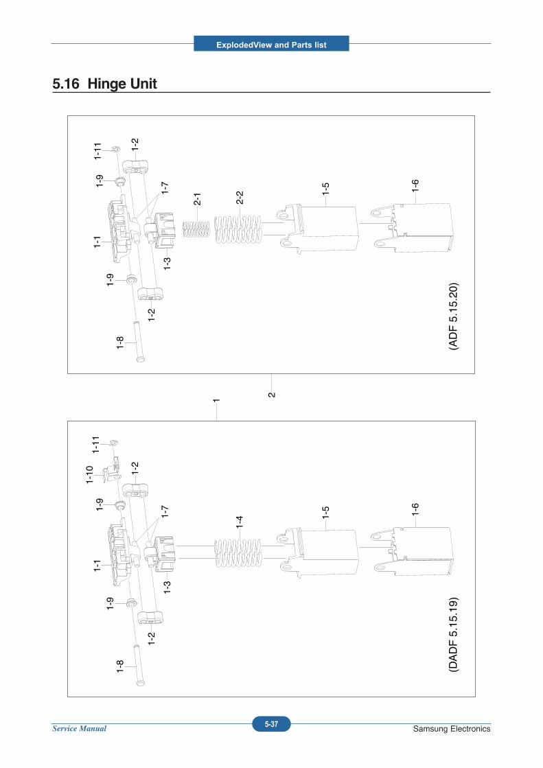
Service Manual
ExplodedView and Parts list
5-37 Samsung Electronics
5.16 Hinge Unit
1
1-1
1-2
1-3
1-2
1-41-7
1-5 1-6
1-8
1-9
1-10
1-9
1-11
2
1-1
1-2
1-3
1-2
1-7
1-5 1-6
1-8
1-9
1-11
1-9
2-1
(DADF 5.15.19)
(ADF 5.15.20)
2-2
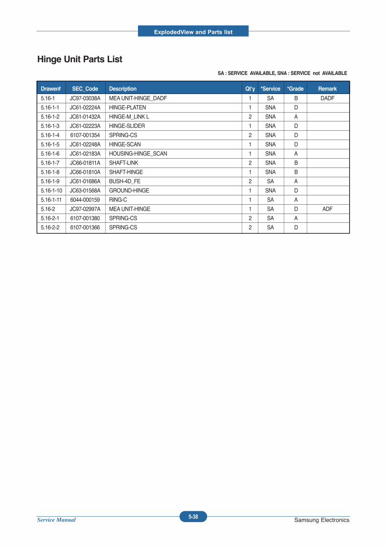
Service Manual
ExplodedView and Parts list
5-38 Samsung Electronics
Hinge Unit Parts ListSA : SERVICE AVAILABLE, SNA : SERVICE not AVAILABLE
5.16-1 JC97-03038A MEAUNIT-HINGE_DADF 1 SA B DADF
5.16-1-1 JC61-02224A HINGE-PLATEN 1 SNA D
5.16-1-2 JC61-01432A HINGE-M_LINK L 2 SNA A
5.16-1-3 JC61-02223A HINGE-SLIDER 1 SNA D
5.16-1-4 6107-001354 SPRING-CS 2 SNA D
5.16-1-5 JC61-02248A HINGE-SCAN 1 SNA D
5.16-1-6 JC61-02183A HOUSING-HINGE_SCAN 1 SNA A
5.16-1-7 JC66-01811A SHAFT-LINK 2 SNA B
5.16-1-8 JC66-01810A SHAFT-HINGE 1 SNA B
5.16-1-9 JC61-01686A BUSH-4D_FE 2 SA A
5.16-1-10 JC63-01568A GROUND-HINGE 1 SNA D
5.16-1-11 6044-000159 RING-C 1 SA A
5.16-2 JC97-02997A MEAUNIT-HINGE 1 SA D ADF
5.16-2-1 6107-001380 SPRING-CS 2 SA A
5.16-2-2 6107-001366 SPRING-CS 2 SA D
Drawer# SEC_Code Description Qt’y *Service *Grade Remark
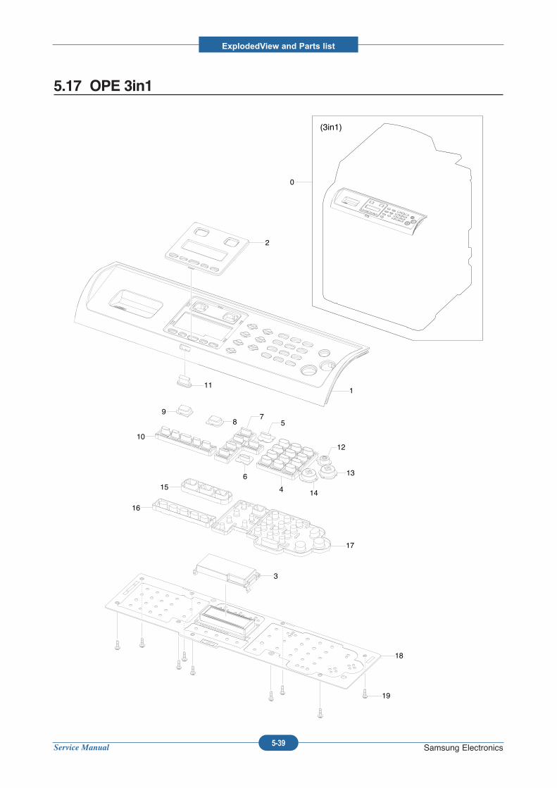
Service Manual
ExplodedView and Parts list
5-39 Samsung Electronics
5.17 OPE 3in1
(3in1)
0
2
111
89
10
75
6
4 14
13
12
15
16
17
3
18
19
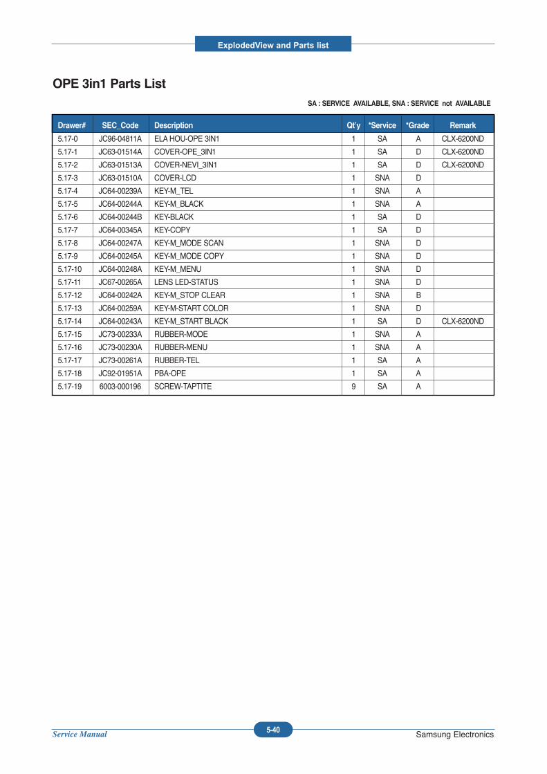
Service Manual
ExplodedView and Parts list
5-40 Samsung Electronics
OPE 3in1 Parts ListSA : SERVICE AVAILABLE, SNA : SERVICE not AVAILABLE
5.17-0 JC96-04811A ELAHOU-OPE 3IN1 1 SA A CLX-6200ND
5.17-1 JC63-01514A COVER-OPE_3IN1 1 SA D CLX-6200ND
5.17-2 JC63-01513A COVER-NEVI_3IN1 1 SA D CLX-6200ND
5.17-3 JC63-01510A COVER-LCD 1 SNA D
5.17-4 JC64-00239A KEY-M_TEL 1 SNA A
5.17-5 JC64-00244A KEY-M_BLACK 1 SNA A
5.17-6 JC64-00244B KEY-BLACK 1 SA D
5.17-7 JC64-00345A KEY-COPY 1 SA D
5.17-8 JC64-00247A KEY-M_MODE SCAN 1 SNA D
5.17-9 JC64-00245A KEY-M_MODE COPY 1 SNA D
5.17-10 JC64-00248A KEY-M_MENU 1 SNA D
5.17-11 JC67-00265A LENS LED-STATUS 1 SNA D
5.17-12 JC64-00242A KEY-M_STOP CLEAR 1 SNA B
5.17-13 JC64-00259A KEY-M-START COLOR 1 SNA D
5.17-14 JC64-00243A KEY-M_START BLACK 1 SA D CLX-6200ND
5.17-15 JC73-00233A RUBBER-MODE 1 SNA A
5.17-16 JC73-00230A RUBBER-MENU 1 SNA A
5.17-17 JC73-00261A RUBBER-TEL 1 SA A
5.17-18 JC92-01951A PBA-OPE 1 SA A
5.17-19 6003-000196 SCREW-TAPTITE 9 SA A
Drawer# SEC_Code Description Qt’y *Service *Grade Remark
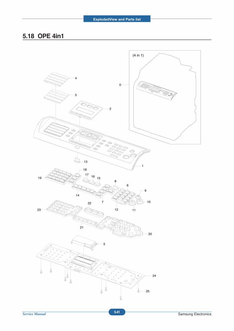
Service Manual
ExplodedView and Parts list
5-41 Samsung Electronics
5.18 OPE 4in1
0
(4 in 1)
4
5
2
113
19
18
17 16 15
14
7
86
9
10
111223
22
21
20
3
24
25
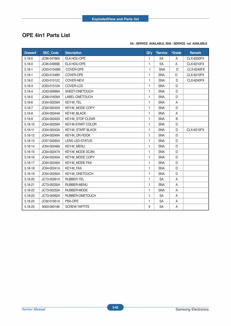
Service Manual
ExplodedView and Parts list
5-42 Samsung Electronics
OPE 4in1 Parts ListSA : SERVICE AVAILABLE, SNA : SERVICE not AVAILABLE
5.18-0 JC96-04786A ELAHOU-OPE 1 SA A CLX-6200FX
5.18-0 JC96-04969E ELAHOU-OPE 1 SA A CLX-6210FX
5.18-1 JC63-01548M COVER-OPE 1 SNA D CLX-6240FX
5.18-1 JC63-01548H COVER-OPE 1 SNA D CLX-6210FX
5.18-2 JC63-01512C COVER-NEVI 1 SNA D CLX-6240FX
5.18-3 JC63-01510A COVER-LCD 1 SNA D
5.18-4 JC63-00999A SHEET-ONETOUCH 1 SNA D
5.18-5 JC68-01639A LABEL-ONETOUCH 1 SNA D
5.18-6 JC64-00239A KEY-M_TEL 1 SNA A
5.18-7 JC64-00245A KEY-M_MODE COPY 1 SNA D
5.18-8 JC64-00244A KEY-M_BLACK 1 SNA A
5.18-9 JC64-00242A KEY-M_STOP CLEAR 1 SNA B
5.18-10 JC64-00259A KEY-M-START COLOR 1 SNA D
5.18-11 JC64-00243A KEY-M_START BLACK 1 SNA D CLX-6210FX
5.18-12 JC64-00249A KEY-M_ON HOOK 1 SNA D
5.18-13 JC67-00265A LENS LED-STATUS 1 SNA D
5.18-14 JC64-00248A KEY-M_MENU 1 SNA D
5.18-15 JC64-00247A KEY-M_MODE SCAN 1 SNA D
5.18-16 JC64-00245A KEY-M_MODE COPY 1 SNA D
5.18-17 JC64-00246A KEY-M_MODE FAX 1 SNA D
5.18-18 JC64-00241A KEY-M_FAX 1 SNA D
5.18-19 JC64-00250A KEY-M_ONETOUCH 1 SNA D
5.18-20 JC73-00261A RUBBER-TEL 1 SA A
5.18-21 JC73-00230A RUBBER-MENU 1 SNA A
5.18-22 JC73-00233A RUBBER-MODE 1 SNA A
5.18-23 JC73-00262A RUBBER-ONETOUCH 1 SA A
5.18-24 JC92-01951A PBA-OPE 1 SA A
5.18-25 6003-000196 SCREW-TAPTITE 9 SA A
Drawer# SEC_Code Description Qt’y *Service *Grade Remark
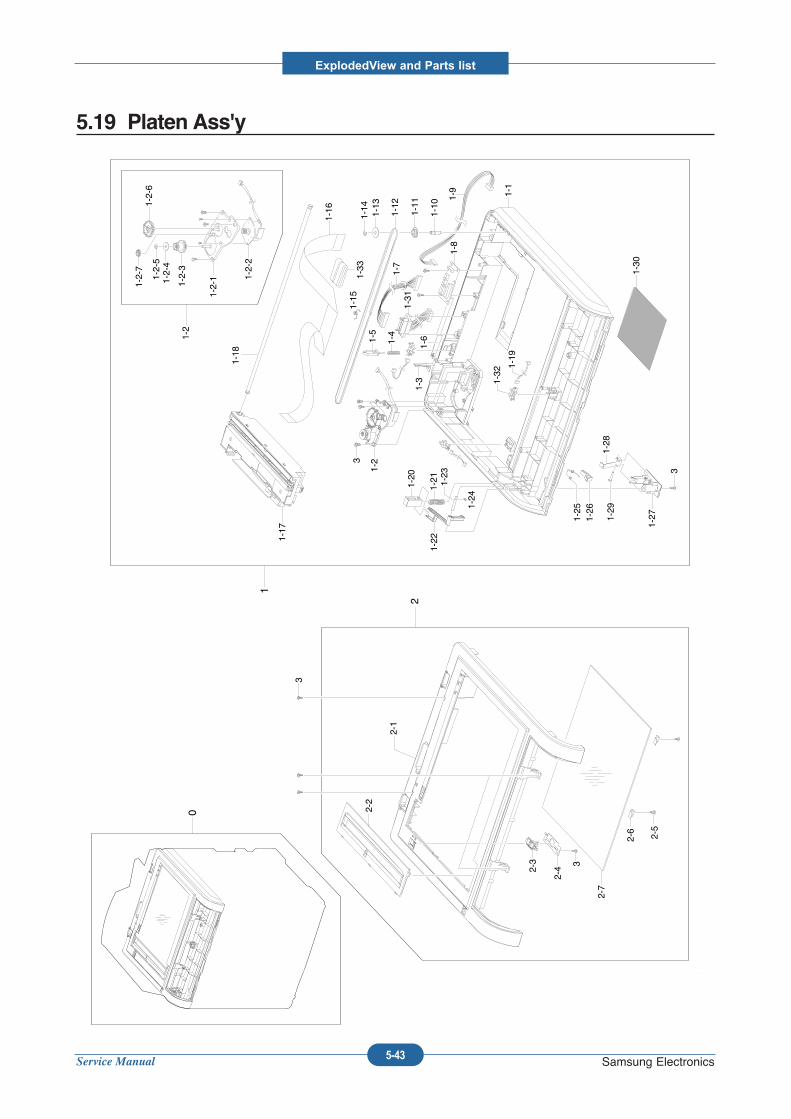
Service Manual
ExplodedView and Parts list
5-43 Samsung Electronics
5.19 Platen Ass'y
0
1
2
2-1
2-2
2-3
2-4 3
2-6
3
2-5
3
3
1-1
1-2
1-4
1-11
1-13
1-31
1-2
1-2-1 1-2-2
1-2-3
1-2-4
1-2-5
1-2-6
1-2-7 1-7
1-8
1-9
1-10
1-15
1-12
1-3
1-5
1-14
1-16
1-17
1-18
1-32
1-19
1-20
1-21
1-22
1-23
1-24
1-25
1-26
1-27
1-28
1-29
1-30
2-7
1-6
1-33
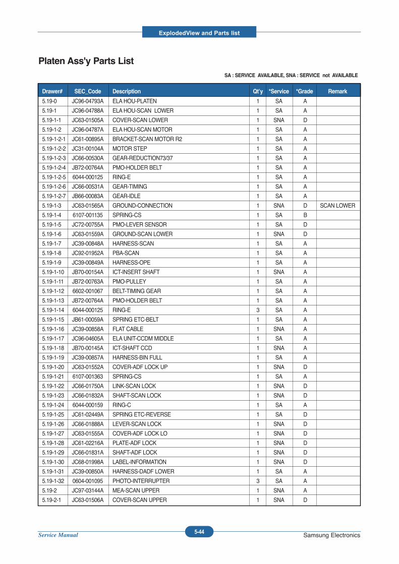
Service Manual
ExplodedView and Parts list
5-44 Samsung Electronics
Platen Ass'y Parts ListSA : SERVICE AVAILABLE, SNA : SERVICE not AVAILABLE
5.19-0 JC96-04793A ELAHOU-PLATEN 1 SA A
5.19-1 JC96-04788A ELAHOU-SCAN LOWER 1 SA A
5.19-1-1 JC63-01505A COVER-SCAN LOWER 1 SNA D
5.19-1-2 JC96-04787A ELAHOU-SCAN MOTOR 1 SA A
5.19-1-2-1 JC61-00895A BRACKET-SCAN MOTOR R2 1 SA A
5.19-1-2-2 JC31-00104A MOTOR STEP 1 SA A
5.19-1-2-3 JC66-00530A GEAR-REDUCTION73/37 1 SA A
5.19-1-2-4 JB72-00764A PMO-HOLDER BELT 1 SA A
5.19-1-2-5 6044-000125 RING-E 1 SA A
5.19-1-2-6 JC66-00531A GEAR-TIMING 1 SA A
5.19-1-2-7 JB66-00083A GEAR-IDLE 1 SA A
5.19-1-3 JC63-01565A GROUND-CONNECTION 1 SNA D SCAN LOWER
5.19-1-4 6107-001135 SPRING-CS 1 SA B
5.19-1-5 JC72-00755A PMO-LEVER SENSOR 1 SA D
5.19-1-6 JC63-01559A GROUND-SCAN LOWER 1 SNA D
5.19-1-7 JC39-00848A HARNESS-SCAN 1 SA A
5.19-1-8 JC92-01952A PBA-SCAN 1 SA A
5.19-1-9 JC39-00849A HARNESS-OPE 1 SA A
5.19-1-10 JB70-00154A ICT-INSERT SHAFT 1 SNA A
5.19-1-11 JB72-00763A PMO-PULLEY 1 SA A
5.19-1-12 6602-001067 BELT-TIMING GEAR 1 SA A
5.19-1-13 JB72-00764A PMO-HOLDER BELT 1 SA A
5.19-1-14 6044-000125 RING-E 3 SA A
5.19-1-15 JB61-00059A SPRING ETC-BELT 1 SA A
5.19-1-16 JC39-00858A FLAT CABLE 1 SNA A
5.19-1-17 JC96-04605A ELAUNIT-CCDM MIDDLE 1 SA A
5.19-1-18 JB70-00145A ICT-SHAFT CCD 1 SNA A
5.19-1-19 JC39-00857A HARNESS-BIN FULL 1 SA A
5.19-1-20 JC63-01552A COVER-ADF LOCK UP 1 SNA D
5.19-1-21 6107-001363 SPRING-CS 1 SA A
5.19-1-22 JC66-01750A LINK-SCAN LOCK 1 SNA D
5.19-1-23 JC66-01832A SHAFT-SCAN LOCK 1 SNA D
5.19-1-24 6044-000159 RING-C 1 SA A
5.19-1-25 JC61-02449A SPRING ETC-REVERSE 1 SA D
5.19-1-26 JC66-01888A LEVER-SCAN LOCK 1 SNA D
5.19-1-27 JC63-01555A COVER-ADF LOCK LO 1 SNA D
5.19-1-28 JC61-02216A PLATE-ADF LOCK 1 SNA D
5.19-1-29 JC66-01831A SHAFT-ADF LOCK 1 SNA D
5.19-1-30 JC68-01998A LABEL-INFORMATION 1 SNA D
5.19-1-31 JC39-00850A HARNESS-DADF LOWER 1 SA A
5.19-1-32 0604-001095 PHOTO-INTERRUPTER 3 SA A
5.19-2 JC97-03144A MEA-SCAN UPPER 1 SNA A
5.19-2-1 JC63-01506A COVER-SCAN UPPER 1 SNA D
Drawer# SEC_Code Description Qt’y *Service *Grade Remark
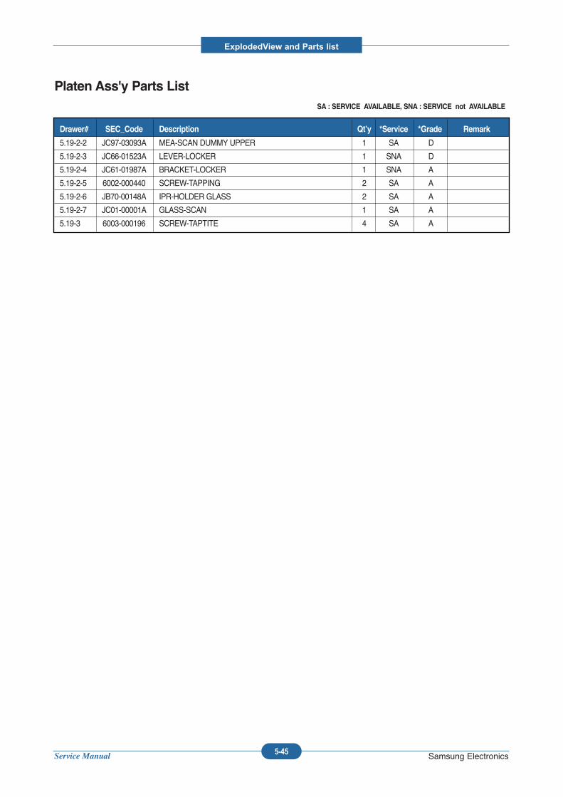
Service Manual
ExplodedView and Parts list
5-45 Samsung Electronics
Platen Ass'y Parts ListSA : SERVICE AVAILABLE, SNA : SERVICE not AVAILABLE
5.19-2-2 JC97-03093A MEA-SCAN DUMMY UPPER 1 SA D
5.19-2-3 JC66-01523A LEVER-LOCKER 1 SNA D
5.19-2-4 JC61-01987A BRACKET-LOCKER 1 SNA A
5.19-2-5 6002-000440 SCREW-TAPPING 2 SA A
5.19-2-6 JB70-00148A IPR-HOLDER GLASS 2 SA A
5.19-2-7 JC01-00001A GLASS-SCAN 1 SA A
5.19-3 6003-000196 SCREW-TAPTITE 4 SA A
Drawer# SEC_Code Description Qt’y *Service *Grade Remark
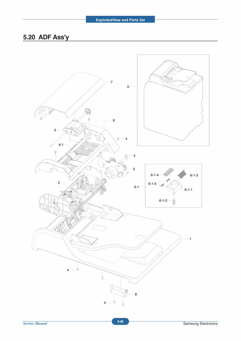
Service Manual
ExplodedView and Parts list
5-46 Samsung Electronics
5.20 ADF Ass'y
07
5
6
6-1
3
2
1
8
6-1
6-1-4 6-1-3
6-1-1
6-1-2
6-1-5
4
4
4
4
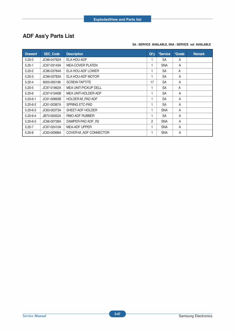
Service Manual
ExplodedView and Parts list
5-47 Samsung Electronics
ADF Ass'y Parts ListSA : SERVICE AVAILABLE, SNA : SERVICE not AVAILABLE
5.20-0 JC96-04792A ELAHOU-ADF 1 SA A
5.20-1 JC97-03143A MEA-COVER PLATEN 1 SNA A
5.20-2 JC96-03784A ELAHOU-ADF LOWER 1 SA A
5.20-3 JC96-03783A ELAHOU-ADF MOTOR 1 SA A
5.20-4 6003-000196 SCREW-TAPTITE 17 SA A
5.20-5 JC97-01962A MEAUNIT-PICKUP DELL 1 SA A
5.20-6 JC97-01940B MEAUNIT-HOLDER ADF 1 SA A
5.20-6-1 JC61-00893B HOLDER-M_PAD ADF 1 SA A
5.20-6-2 JC61-00387A SPRING ETC-PAD 1 SA A
5.20-6-3 JC63-00373A SHEET-ADF HOLDER 1 SNA A
5.20-6-4 JB73-00052A RMO-ADF RUBBER 1 SA A
5.20-6-5 JC66-00738A DAMPER-PAD ADF_R2 2 SNA A
5.20-7 JC97-02410A MEA-ADF UPPER 1 SNA A
5.20-8 JC63-00998A COVER-M_ADF CONNECTOR 1 SNA A
Drawer# SEC_Code Description Qt’y *Service *Grade Remark
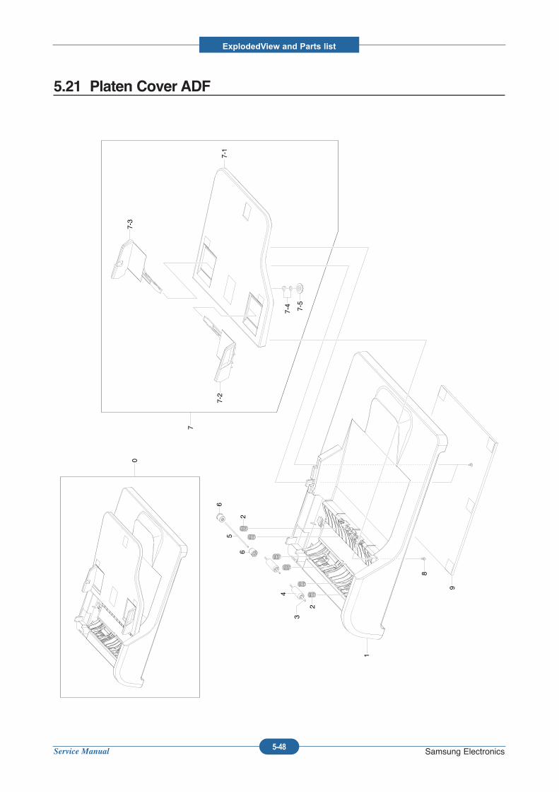
Service Manual
ExplodedView and Parts list
5-48 Samsung Electronics
5.21 Platen Cover ADF
0
1
2
3
4
2
5
6
6
7
7-1
7-2
7-3
7-4 7-5
8
9
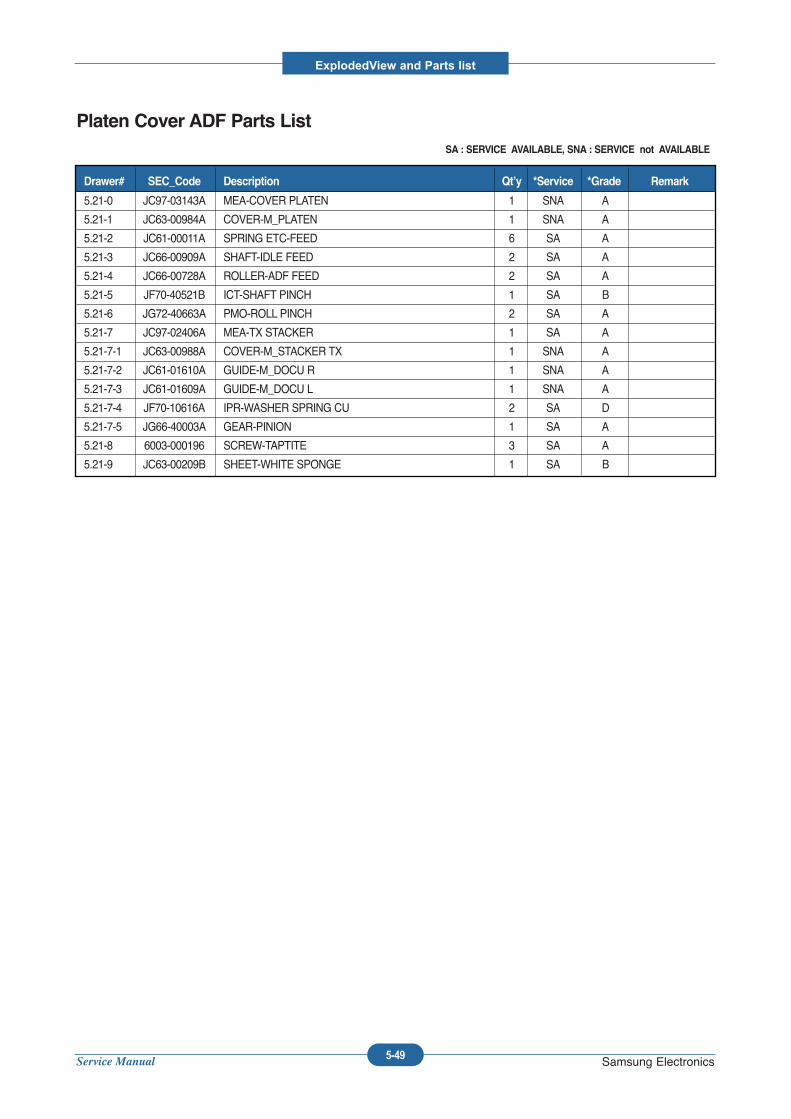
Service Manual
ExplodedView and Parts list
5-49 Samsung Electronics
Platen Cover ADF Parts ListSA : SERVICE AVAILABLE, SNA : SERVICE not AVAILABLE
5.21-0 JC97-03143A MEA-COVER PLATEN 1 SNA A
5.21-1 JC63-00984A COVER-M_PLATEN 1 SNA A
5.21-2 JC61-00011A SPRING ETC-FEED 6 SA A
5.21-3 JC66-00909A SHAFT-IDLE FEED 2 SA A
5.21-4 JC66-00728A ROLLER-ADF FEED 2 SA A
5.21-5 JF70-40521B ICT-SHAFT PINCH 1 SA B
5.21-6 JG72-40663A PMO-ROLL PINCH 2 SA A
5.21-7 JC97-02406A MEA-TX STACKER 1 SA A
5.21-7-1 JC63-00988A COVER-M_STACKER TX 1 SNA A
5.21-7-2 JC61-01610A GUIDE-M_DOCU R 1 SNA A
5.21-7-3 JC61-01609A GUIDE-M_DOCU L 1 SNA A
5.21-7-4 JF70-10616A IPR-WASHER SPRING CU 2 SA D
5.21-7-5 JG66-40003A GEAR-PINION 1 SA A
5.21-8 6003-000196 SCREW-TAPTITE 3 SA A
5.21-9 JC63-00209B SHEET-WHITE SPONGE 1 SA B
Drawer# SEC_Code Description Qt’y *Service *Grade Remark
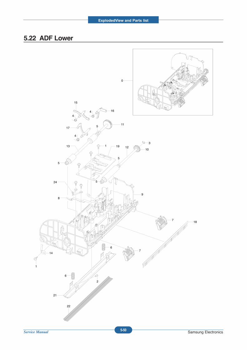
Service Manual
ExplodedView and Parts list
5-50 Samsung Electronics
5.22 ADF Lower
0
1644
4
15
1711
10
312
5
5
5
5
13 191
24
89
718
1
14
6
2
21
22
76
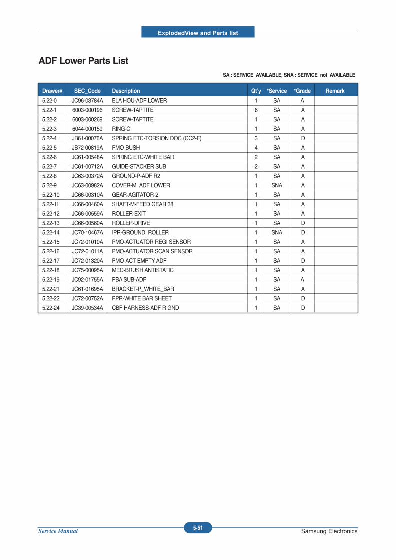
Service Manual
ExplodedView and Parts list
5-51 Samsung Electronics
ADF Lower Parts ListSA : SERVICE AVAILABLE, SNA : SERVICE not AVAILABLE
5.22-0 JC96-03784A ELAHOU-ADF LOWER 1 SA A
5.22-1 6003-000196 SCREW-TAPTITE 6 SA A
5.22-2 6003-000269 SCREW-TAPTITE 1 SA A
5.22-3 6044-000159 RING-C 1 SA A
5.22-4 JB61-00076A SPRING ETC-TORSION DOC (CC2-F) 3 SA D
5.22-5 JB72-00819A PMO-BUSH 4 SA A
5.22-6 JC61-00548A SPRING ETC-WHITE BAR 2 SA A
5.22-7 JC61-00712A GUIDE-STACKER SUB 2 SA A
5.22-8 JC63-00372A GROUND-P-ADF R2 1 SA A
5.22-9 JC63-00982A COVER-M_ADF LOWER 1 SNA A
5.22-10 JC66-00310A GEAR-AGITATOR-2 1 SA A
5.22-11 JC66-00460A SHAFT-M-FEED GEAR 38 1 SA A
5.22-12 JC66-00559A ROLLER-EXIT 1 SA A
5.22-13 JC66-00560A ROLLER-DRIVE 1 SA D
5.22-14 JC70-10467A IPR-GROUND_ROLLER 1 SNA D
5.22-15 JC72-01010A PMO-ACTUATOR REGI SENSOR 1 SA A
5.22-16 JC72-01011A PMO-ACTUATOR SCAN SENSOR 1 SA A
5.22-17 JC72-01320A PMO-ACT EMPTYADF 1 SA D
5.22-18 JC75-00095A MEC-BRUSH ANTISTATIC 1 SA A
5.22-19 JC92-01755A PBASUB-ADF 1 SA A
5.22-21 JC61-01695A BRACKET-P_WHITE_BAR 1 SA A
5.22-22 JC72-00752A PPR-WHITE BAR SHEET 1 SA D
5.22-24 JC39-00534A CBF HARNESS-ADF R GND 1 SA D
Drawer# SEC_Code Description Qt’y *Service *Grade Remark
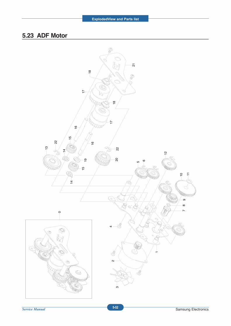
Service Manual
ExplodedView and Parts list
5-52 Samsung Electronics
5.23 ADF Motor
0
1
23
4
5 6
78
910 11
12
13
14
15
16
17
1819 20
21
14
15
16
1718
22
22
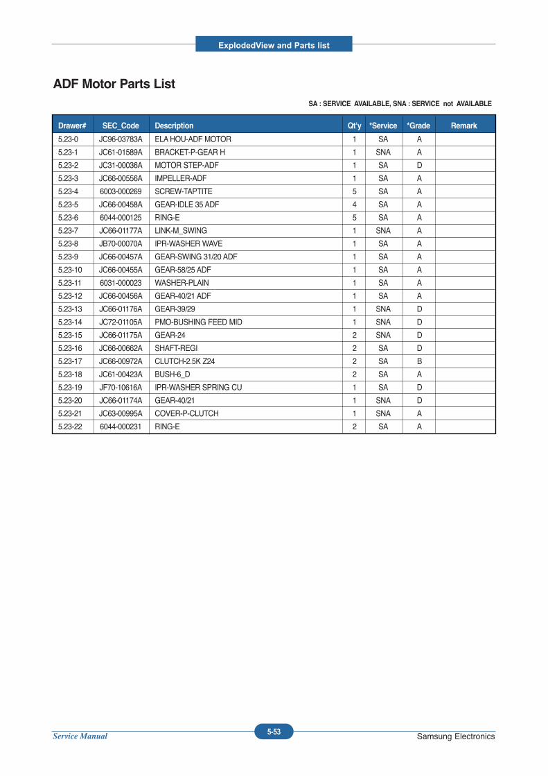
Service Manual
ExplodedView and Parts list
5-53 Samsung Electronics
ADF Motor Parts ListSA : SERVICE AVAILABLE, SNA : SERVICE not AVAILABLE
5.23-0 JC96-03783A ELAHOU-ADF MOTOR 1 SA A
5.23-1 JC61-01589A BRACKET-P-GEAR H 1 SNA A
5.23-2 JC31-00036A MOTOR STEP-ADF 1 SA D
5.23-3 JC66-00556A IMPELLER-ADF 1 SA A
5.23-4 6003-000269 SCREW-TAPTITE 5 SA A
5.23-5 JC66-00458A GEAR-IDLE 35 ADF 4 SA A
5.23-6 6044-000125 RING-E 5 SA A
5.23-7 JC66-01177A LINK-M_SWING 1 SNA A
5.23-8 JB70-00070A IPR-WASHER WAVE 1 SA A
5.23-9 JC66-00457A GEAR-SWING 31/20 ADF 1 SA A
5.23-10 JC66-00455A GEAR-58/25 ADF 1 SA A
5.23-11 6031-000023 WASHER-PLAIN 1 SA A
5.23-12 JC66-00456A GEAR-40/21 ADF 1 SA A
5.23-13 JC66-01176A GEAR-39/29 1 SNA D
5.23-14 JC72-01105A PMO-BUSHING FEED MID 1 SNA D
5.23-15 JC66-01175A GEAR-24 2 SNA D
5.23-16 JC66-00662A SHAFT-REGI 2 SA D
5.23-17 JC66-00972A CLUTCH-2.5K Z24 2 SA B
5.23-18 JC61-00423A BUSH-6_D 2 SA A
5.23-19 JF70-10616A IPR-WASHER SPRING CU 1 SA D
5.23-20 JC66-01174A GEAR-40/21 1 SNA D
5.23-21 JC63-00995A COVER-P-CLUTCH 1 SNA A
5.23-22 6044-000231 RING-E 2 SA A
Drawer# SEC_Code Description Qt’y *Service *Grade Remark
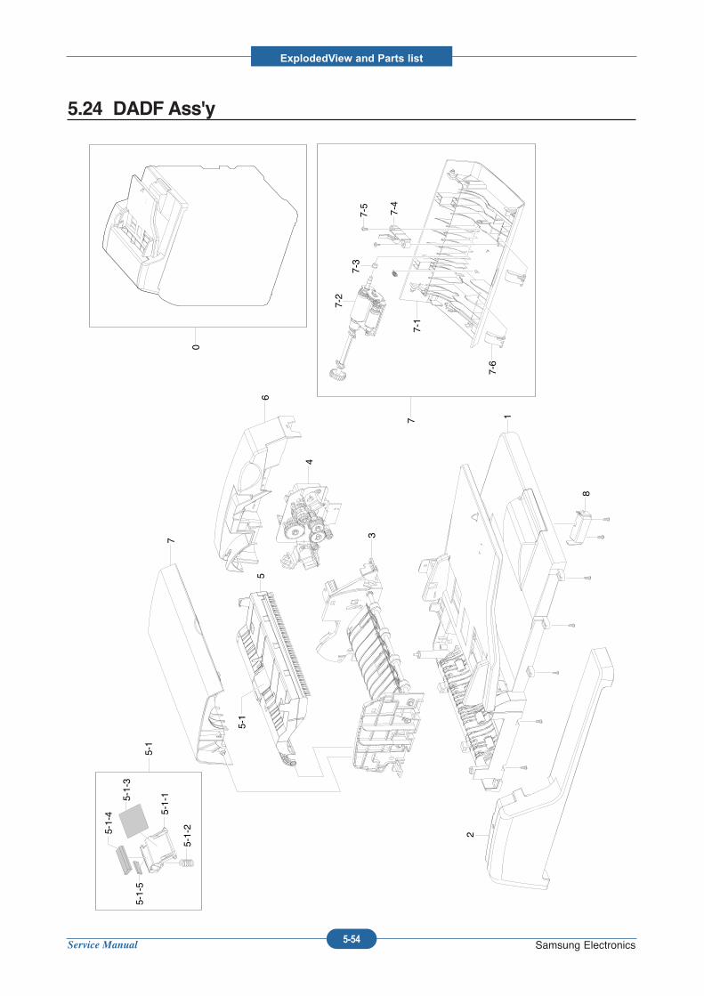
Service Manual
ExplodedView and Parts list
5-54 Samsung Electronics
5.24 DADF Ass'y
0
1
2
3
4
56
7
5-1
5-1
5-1-15-1-3
5-1-25-1-4
5-1-5
77-1
7-2
7-3
7-4
7-5
7-6
8
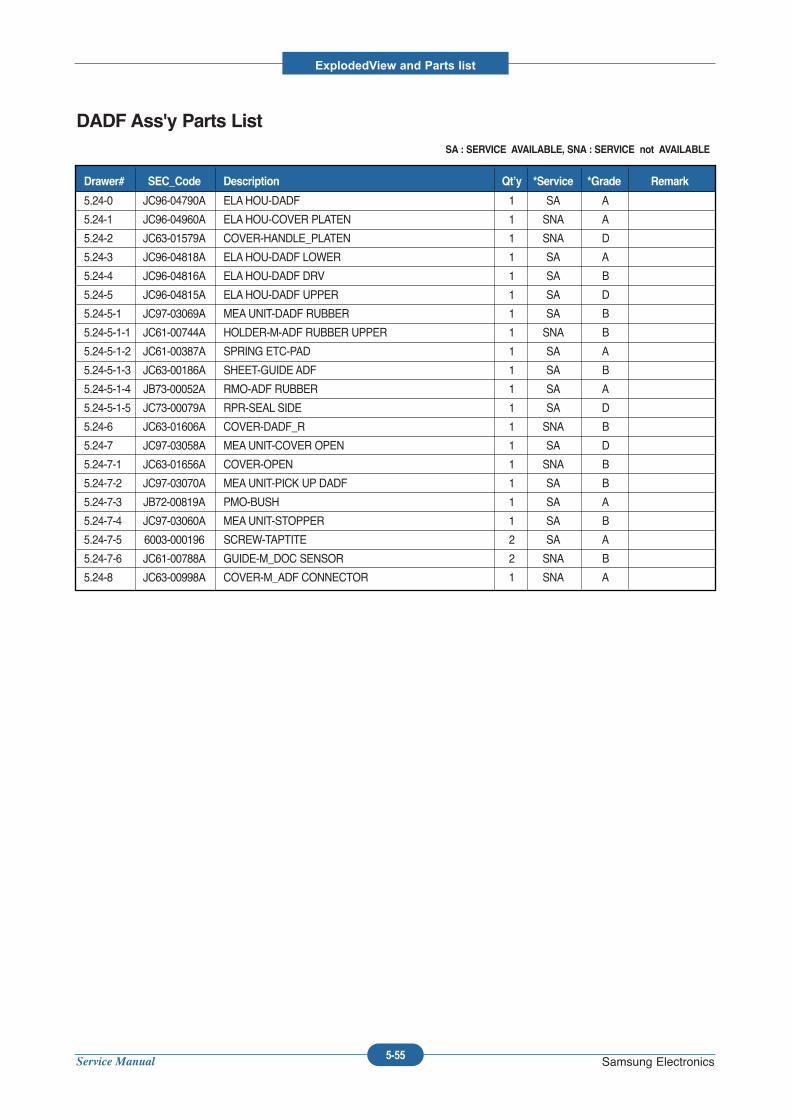
Service Manual
ExplodedView and Parts list
5-55 Samsung Electronics
DADF Ass'y Parts ListSA : SERVICE AVAILABLE, SNA : SERVICE not AVAILABLE
5.24-0 JC96-04790A ELAHOU-DADF 1 SA A
5.24-1 JC96-04960A ELAHOU-COVER PLATEN 1 SNA A
5.24-2 JC63-01579A COVER-HANDLE_PLATEN 1 SNA D
5.24-3 JC96-04818A ELAHOU-DADF LOWER 1 SA A
5.24-4 JC96-04816A ELAHOU-DADF DRV 1 SA B
5.24-5 JC96-04815A ELAHOU-DADF UPPER 1 SA D
5.24-5-1 JC97-03069A MEAUNIT-DADF RUBBER 1 SA B
5.24-5-1-1 JC61-00744A HOLDER-M-ADF RUBBER UPPER 1 SNA B
5.24-5-1-2 JC61-00387A SPRING ETC-PAD 1 SA A
5.24-5-1-3 JC63-00186A SHEET-GUIDE ADF 1 SA B
5.24-5-1-4 JB73-00052A RMO-ADF RUBBER 1 SA A
5.24-5-1-5 JC73-00079A RPR-SEAL SIDE 1 SA D
5.24-6 JC63-01606A COVER-DADF_R 1 SNA B
5.24-7 JC97-03058A MEAUNIT-COVER OPEN 1 SA D
5.24-7-1 JC63-01656A COVER-OPEN 1 SNA B
5.24-7-2 JC97-03070A MEAUNIT-PICK UP DADF 1 SA B
5.24-7-3 JB72-00819A PMO-BUSH 1 SA A
5.24-7-4 JC97-03060A MEAUNIT-STOPPER 1 SA B
5.24-7-5 6003-000196 SCREW-TAPTITE 2 SA A
5.24-7-6 JC61-00788A GUIDE-M_DOC SENSOR 2 SNA B
5.24-8 JC63-00998A COVER-M_ADF CONNECTOR 1 SNA A
Drawer# SEC_Code Description Qt’y *Service *Grade Remark
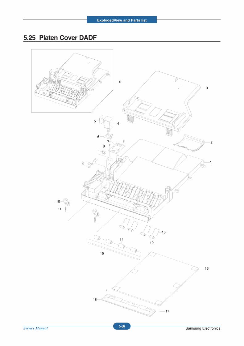
Service Manual
ExplodedView and Parts list
5-56 Samsung Electronics
5.25 Platen Cover DADF
0
1
2
3
45
6
78
9
10
11
12
13
14
15
16
17
18
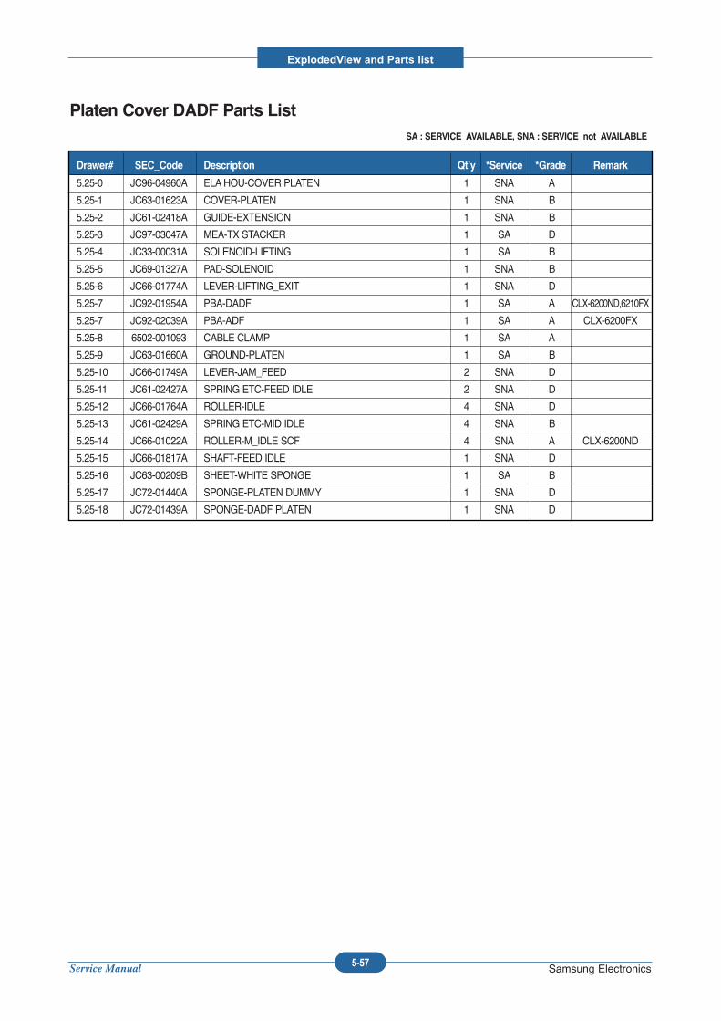
Service Manual
ExplodedView and Parts list
5-57 Samsung Electronics
Platen Cover DADF Parts ListSA : SERVICE AVAILABLE, SNA : SERVICE not AVAILABLE
5.25-0 JC96-04960A ELAHOU-COVER PLATEN 1 SNA A
5.25-1 JC63-01623A COVER-PLATEN 1 SNA B
5.25-2 JC61-02418A GUIDE-EXTENSION 1 SNA B
5.25-3 JC97-03047A MEA-TX STACKER 1 SA D
5.25-4 JC33-00031A SOLENOID-LIFTING 1 SA B
5.25-5 JC69-01327A PAD-SOLENOID 1 SNA B
5.25-6 JC66-01774A LEVER-LIFTING_EXIT 1 SNA D
5.25-7 JC92-01954A PBA-DADF 1 SA A CLX-6200ND,6210FX
5.25-7 JC92-02039A PBA-ADF 1 SA A CLX-6200FX
5.25-8 6502-001093 CABLE CLAMP 1 SA A
5.25-9 JC63-01660A GROUND-PLATEN 1 SA B
5.25-10 JC66-01749A LEVER-JAM_FEED 2 SNA D
5.25-11 JC61-02427A SPRING ETC-FEED IDLE 2 SNA D
5.25-12 JC66-01764A ROLLER-IDLE 4 SNA D
5.25-13 JC61-02429A SPRING ETC-MID IDLE 4 SNA B
5.25-14 JC66-01022A ROLLER-M_IDLE SCF 4 SNA A CLX-6200ND
5.25-15 JC66-01817A SHAFT-FEED IDLE 1 SNA D
5.25-16 JC63-00209B SHEET-WHITE SPONGE 1 SA B
5.25-17 JC72-01440A SPONGE-PLATEN DUMMY 1 SNA D
5.25-18 JC72-01439A SPONGE-DADF PLATEN 1 SNA D
Drawer# SEC_Code Description Qt’y *Service *Grade Remark
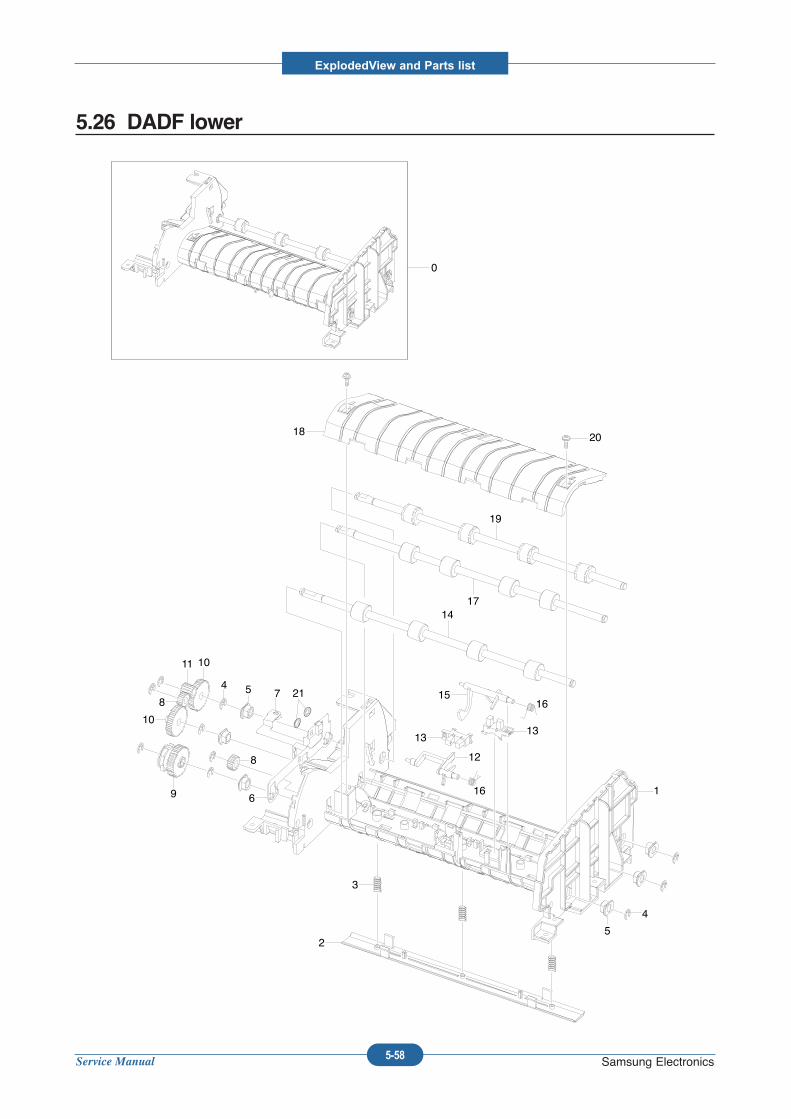
Service Manual
ExplodedView and Parts list
5-58 Samsung Electronics
5.26 DADF lower
0
2018
19
1714
1516
16
12
1313
1
5
4
3
2
54
1011
8
10
8
9 6
7 21
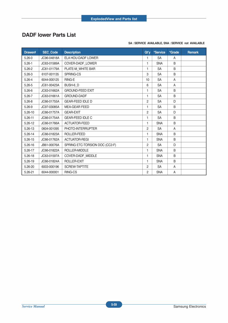
Service Manual
ExplodedView and Parts list
5-59 Samsung Electronics
DADF lower Parts ListSA : SERVICE AVAILABLE, SNA : SERVICE not AVAILABLE
5.26-0 JC96-04818A ELAHOU-DADF LOWER 1 SA A
5.26-1 JC63-01589A COVER-DADF_LOWER 1 SNA B
5.26-2 JC61-01179A PLATE-M_WHITE BAR 1 SA B
5.26-3 6107-001135 SPRING-CS 3 SA B
5.26-4 6044-000125 RING-E 10 SA A
5.26-5 JC61-00423A BUSH-6_D 6 SA A
5.26-6 JC63-01662A GROUND-FEED EXIT 1 SA B
5.26-7 JC63-01661A GROUND-DADF 1 SA B
5.26-8 JC66-01755A GEAR-FEED IDLE D 2 SA D
5.26-9 JC97-03085A MEA-GEAR FEED 1 SA B
5.26-10 JC66-01757A GEAR-EXIT 2 SA D
5.26-11 JC66-01754A GEAR-FEED IDLE C 1 SA B
5.26-12 JC66-01766A ACTUATOR-FEED 1 SNA B
5.26-13 0604-001095 PHOTO-INTERRUPTER 2 SA A
5.26-14 JC66-01823A ROLLER-FEED 1 SNA B
5.26-15 JC66-01762A ACTUATOR-REGI 1 SNA B
5.26-16 JB61-00076A SPRING ETC-TORSION DOC (CC2-F) 2 SA D
5.26-17 JC66-01822A ROLLER-MIDDLE 1 SNA B
5.26-18 JC63-01597A COVER-DADF_MIDDLE 1 SNA B
5.26-19 JC66-01824A ROLLER-EXIT 1 SNA B
5.26-20 6003-000196 SCREW-TAPTITE 2 SA A
5.26-21 6044-000001 RING-CS 2 SNA A
Drawer# SEC_Code Description Qt’y *Service *Grade Remark
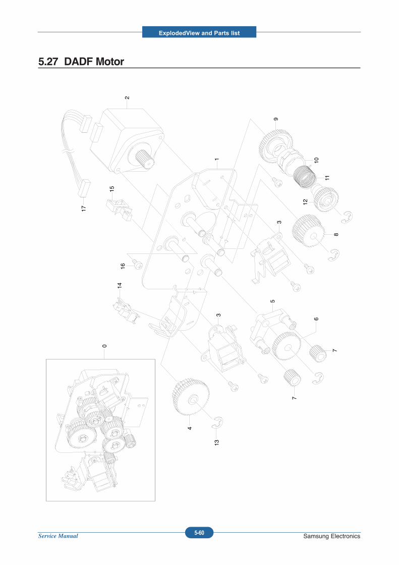
Service Manual
ExplodedView and Parts list
5-60 Samsung Electronics
5.27 DADF Motor
0
17
15
2
1
1614
4
133
5
6
7
7
3
8
12
11
10
9
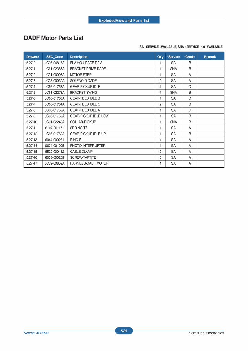
Service Manual
ExplodedView and Parts list
5-61 Samsung Electronics
DADF Motor Parts ListSA : SERVICE AVAILABLE, SNA : SERVICE not AVAILABLE
5.27-0 JC96-04816A ELAHOU-DADF DRV 1 SA B
5.27-1 JC61-02386A BRACKET-DRIVE DADF 1 SNA B
5.27-2 JC31-00096A MOTOR STEP 1 SA A
5.27-3 JC33-00030A SOLENOID-DADF 2 SA A
5.27-4 JC66-01758A GEAR-PICKUP IDLE 1 SA D
5.27-5 JC61-02278A BRACKET-SWING 1 SNA B
5.27-6 JC66-01753A GEAR-FEED IDLE B 1 SA D
5.27-7 JC66-01754A GEAR-FEED IDLE C 2 SA B
5.27-8 JC66-01752A GEAR-FEED IDLE A 1 SA D
5.27-9 JC66-01759A GEAR-PICKUP IDLE LOW 1 SA B
5.27-10 JC61-02240A COLLAR-PICKUP 1 SNA B
5.27-11 6107-001171 SPRING-TS 1 SA A
5.27-12 JC66-01760A GEAR-PICKUP IDLE UP 1 SA B
5.27-13 6044-000231 RING-E 4 SA A
5.27-14 0604-001095 PHOTO-INTERRUPTER 1 SA A
5.27-15 6502-000132 CABLE CLAMP 2 SA A
5.27-16 6003-000269 SCREW-TAPTITE 6 SA A
5.27-17 JC39-00852A HARNESS-DADF MOTOR 1 SA A
Drawer# SEC_Code Description Qt’y *Service *Grade Remark
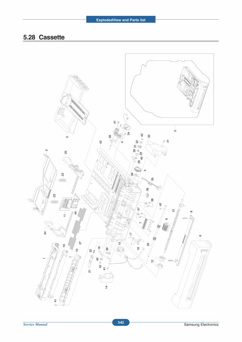
Service Manual
ExplodedView and Parts list
5-62 Samsung Electronics
5.28 Cassette
25
24
23
23
2
3
0
11
44
27
1
19
10 2221
143916
4042
15
18
17
737
38
36
35
39
5
2840
29
3031
32
42 3326
4
34
41
41
41
41
20
42
9
13 8
6
12
43
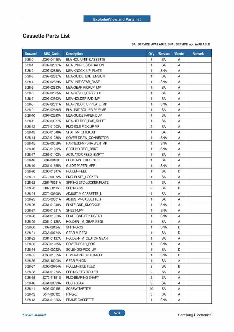
Service Manual
ExplodedView and Parts list
5-63 Samsung Electronics
Cassette Parts ListSA : SERVICE AVAILABLE, SNA : SERVICE not AVAILABLE
5.28-0 JC96-04498A ELAHOU-UNIT_CASSETTE 1 SA A
5.28-1 JC97-02897A MEAUNIT-REGISTRATION 1 SA A
5.28-2 JC97-02888A MEA-KNOCK_UP_PLATE 1 SNA A
5.28-3 JC97-02887A MEA-GUIDE_EXETENSION 1 SA A
5.28-4 JC97-02889A MEAUNIT-GEAR_BASE 1 SNA A
5.28-5 JC97-02893A MEA-GEAR PICKUP_MP 1 SA A
5.28-6 JC97-02885A MEA-COVER_CASSETTE 1 SA A
5.28-7 JC97-02892A MEA-HOLDER PAD_MP 1 SA A
5.28-8 JC97-02891A MEA-KNOCK_UPP LATE_MP 1 SNA A
5.28-9 JC96-02686B ELAUNIT-ROLLER P/UP MP 1 SA A
5.28-10 JC97-02890A MEA-GUIDE PAPER DUP 1 SA A
5.28-11 JC97-03077A MEA-HOLDER_PAD_SHEET 1 SA A
5.28-12 JC72-01003A PMO-IDLE PICK UP MP 2 SA A
5.28-13 JC66-01348A SHAFT-MP_PICK_UP 1 SA A
5.28-14 JC63-01286A COVER-DRAW_CONNECTOR 1 SNA A
5.28-15 JC39-00659A HARNESS-MPDRAWER_MP 1 SNA A
5.28-16 JC63-01282A GROUND-REGI_BRKT 1 SNA A
5.28-17 JC66-01403A ACTUATOR-FEED_EMPTY 1 SA A
5.28-18 0604-001095 PHOTO-INTERRUPTER 1 SA A
5.28-19 JC61-01865A GUIDE-PAPER_MPF 1 SNA A
5.28-20 JC66-01347A ROLLER-FEED 1 SA D
5.28-21 JC72-00972A PMO-PLATE_LOCKER 1 SA A
5.28-22 JG61-70531A SPRING ETC-LOCKER,PLATE 1 SA A
5.28-23 6107-001166 SPRING-CS 2 SA B
5.28-24 JC70-00300A ADJUST-M-CASSETTE_L 1 SA A
5.28-25 JC70-00301A ADJUST-M-CASSETTE_R 1 SA A
5.28-26 JC61-01940A PLATE-GND_KNOCKUP 1 SNA A
5.28-27 JC63-01291A SHEET-MPF 1 SNA A
5.28-28 JC61-01923A PLATE-GND-BRKT-GEAR 1 SNA A
5.28-29 JC61-01128A HOLDER-_M_GEAR REGI 1 SA A
5.28-30 6107-001249 SPRING-CS 1 SNA D
5.28-31 JC66-00774A GEAR-M-REGI 1 SA D
5.28-32 JC61-01127A HOLDER-_M_CLUTCH GEAR 1 SA A
5.28-33 JC63-01285A COVER-GEAR_BOX 1 SNA A
5.28-34 JC33-00022A SOLENOID-PICK_UP 1 SA D
5.28-35 JC66-01355A LEVER-LINK_INDICATOR 1 SNA D
5.28-36 JG66-40003A GEAR-PINION 1 SA A
5.28-37 JC66-00764A ROLLER-IDLE FEED 2 SA B
5.28-38 JC61-01274A SPRING ETC-ROLLER 2 SA A
5.28-39 JC72-41191B PMO-BEARING SHAFT 2 SA A
5.28-40 JC61-00699A BUSH-D6/L4 2 SA A
5.28-41 6003-000196 SCREW-TAPTITE 10 SA A
5.28-42 6044-000125 RING-E 3 SA A
5.28-43 JC61-01856A FRAME-CASSETTE 1 SNA A
Drawer# SEC_Code Description Qt’y *Service *Grade Remark
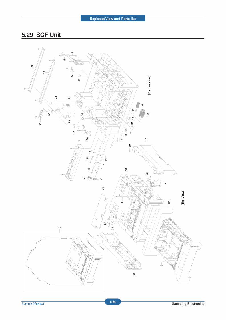
Service Manual
ExplodedView and Parts list
5-64 Samsung Electronics
5.29 SCF Unit
0
(Top View)
(Bottom View)
30
38
31
32
33
35
34
7
36
8
37
39
3 9
1112
13
1415
10
1 16
26
21
25
24
20
23 6
2222
275
28
29
29
18
1918
1719
4
2
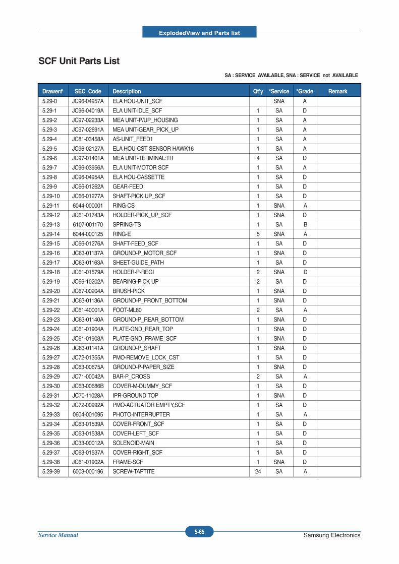
Service Manual
ExplodedView and Parts list
5-65 Samsung Electronics
SCF Unit Parts ListSA : SERVICE AVAILABLE, SNA : SERVICE not AVAILABLE
5.29-0 JC96-04957A ELAHOU-UNIT_SCF SNA A
5.29-1 JC96-04019A ELAUNIT-IDLE_SCF 1 SA D
5.29-2 JC97-02233A MEAUNIT-P/UP_HOUSING 1 SA A
5.29-3 JC97-02691A MEAUNIT-GEAR_PICK_UP 1 SA A
5.29-4 JC81-03458A AS-UNIT_FEED1 1 SA A
5.29-5 JC96-02127A ELAHOU-CST SENSOR HAWK16 1 SA A
5.29-6 JC97-01401A MEAUNIT-TERMINAL:TR 4 SA D
5.29-7 JC96-03956A ELAUNIT-MOTOR SCF 1 SA A
5.29-8 JC96-04954A ELAHOU-CASSETTE 1 SA D
5.29-9 JC66-01262A GEAR-FEED 1 SA D
5.29-10 JC66-01277A SHAFT-PICK UP_SCF 1 SA D
5.29-11 6044-000001 RING-CS 1 SNA A
5.29-12 JC61-01743A HOLDER-PICK_UP_SCF 1 SNA D
5.29-13 6107-001170 SPRING-TS 1 SA B
5.29-14 6044-000125 RING-E 5 SNA A
5.29-15 JC66-01276A SHAFT-FEED_SCF 1 SA D
5.29-16 JC63-01137A GROUND-P_MOTOR_SCF 1 SNA D
5.29-17 JC63-01163A SHEET-GUIDE_PATH 1 SA D
5.29-18 JC61-01579A HOLDER-P-REGI 2 SNA D
5.29-19 JC66-10202A BEARING-PICK UP 2 SA D
5.29-20 JC67-00204A BRUSH-PICK 1 SNA D
5.29-21 JC63-01136A GROUND-P_FRONT_BOTTOM 1 SNA D
5.29-22 JC61-40001A FOOT-ML80 2 SA A
5.29-23 JC63-01140A GROUND-P_REAR_BOTTOM 1 SNA D
5.29-24 JC61-01904A PLATE-GND_REAR_TOP 1 SNA D
5.29-25 JC61-01903A PLATE-GND_FRAME_SCF 1 SNA D
5.29-26 JC63-01141A GROUND-P_SHAFT 1 SNA D
5.29-27 JC72-01355A PMO-REMOVE_LOCK_CST 1 SA D
5.29-28 JC63-00675A GROUND-P-PAPER_SIZE 1 SNA D
5.29-29 JC71-00042A BAR-P_CROSS 2 SA A
5.29-30 JC63-00686B COVER-M-DUMMY_SCF 1 SA D
5.29-31 JC70-11028A IPR-GROUND TOP 1 SNA D
5.29-32 JC72-00992A PMO-ACTUATOR EMPTY,SCF 1 SA D
5.29-33 0604-001095 PHOTO-INTERRUPTER 1 SA A
5.29-34 JC63-01539A COVER-FRONT_SCF 1 SA D
5.29-35 JC63-01538A COVER-LEFT_SCF 1 SA D
5.29-36 JC33-00012A SOLENOID-MAIN 1 SA D
5.29-37 JC63-01537A COVER-RIGHT_SCF 1 SA D
5.29-38 JC61-01902A FRAME-SCF 1 SNA D
5.29-39 6003-000196 SCREW-TAPTITE 24 SA A
Drawer# SEC_Code Description Qt’y *Service *Grade Remark
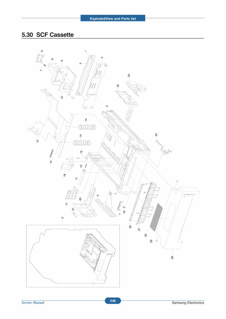
Service Manual
ExplodedView and Parts list
5-66 Samsung Electronics
5.30 SCF Cassette
0
15
13
14
14
67
8
910
4
5
28
29
25
27
26
161
3
20
21
17
11
12
18
19
24
2
22
23
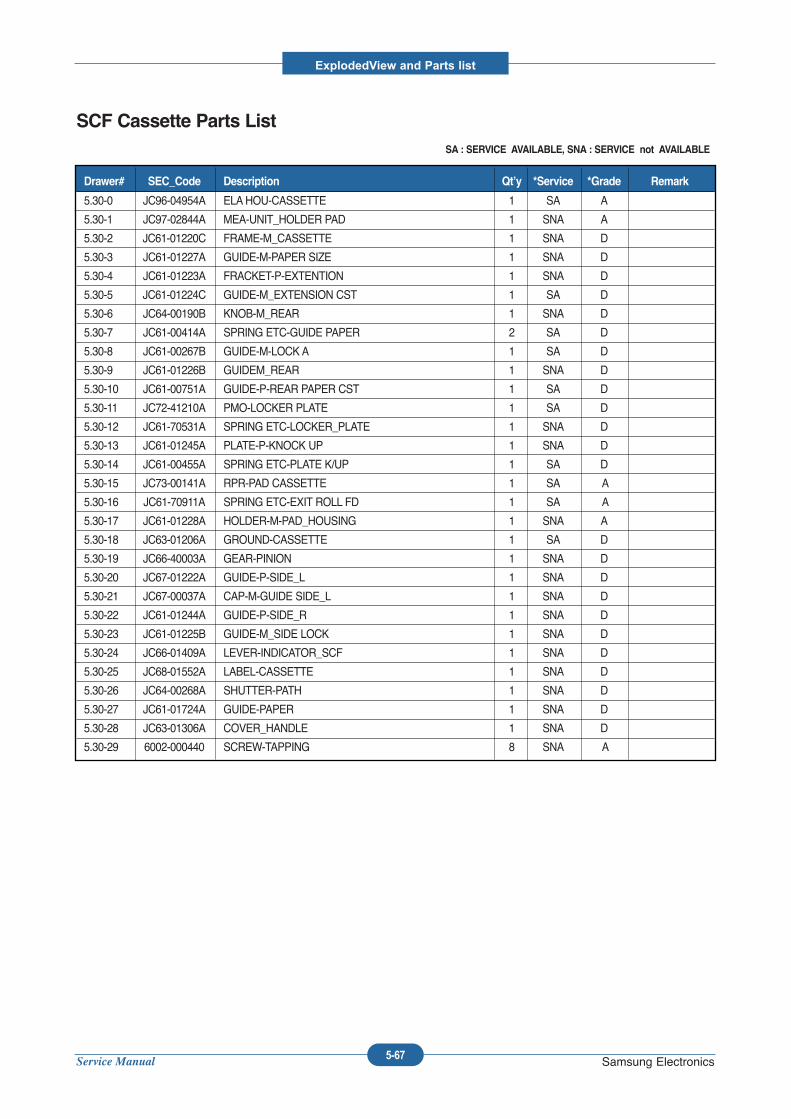
Service Manual
ExplodedView and Parts list
5-67 Samsung Electronics
SCF Cassette Parts ListSA : SERVICE AVAILABLE, SNA : SERVICE not AVAILABLE
5.30-0 JC96-04954A ELAHOU-CASSETTE 1 SA A
5.30-1 JC97-02844A MEA-UNIT_HOLDER PAD 1 SNA A
5.30-2 JC61-01220C FRAME-M_CASSETTE 1 SNA D
5.30-3 JC61-01227A GUIDE-M-PAPER SIZE 1 SNA D
5.30-4 JC61-01223A FRACKET-P-EXTENTION 1 SNA D
5.30-5 JC61-01224C GUIDE-M_EXTENSION CST 1 SA D
5.30-6 JC64-00190B KNOB-M_REAR 1 SNA D
5.30-7 JC61-00414A SPRING ETC-GUIDE PAPER 2 SA D
5.30-8 JC61-00267B GUIDE-M-LOCK A 1 SA D
5.30-9 JC61-01226B GUIDEM_REAR 1 SNA D
5.30-10 JC61-00751A GUIDE-P-REAR PAPER CST 1 SA D
5.30-11 JC72-41210A PMO-LOCKER PLATE 1 SA D
5.30-12 JC61-70531A SPRING ETC-LOCKER_PLATE 1 SNA D
5.30-13 JC61-01245A PLATE-P-KNOCK UP 1 SNA D
5.30-14 JC61-00455A SPRING ETC-PLATE K/UP 1 SA D
5.30-15 JC73-00141A RPR-PAD CASSETTE 1 SA A
5.30-16 JC61-70911A SPRING ETC-EXIT ROLL FD 1 SA A
5.30-17 JC61-01228A HOLDER-M-PAD_HOUSING 1 SNA A
5.30-18 JC63-01206A GROUND-CASSETTE 1 SA D
5.30-19 JC66-40003A GEAR-PINION 1 SNA D
5.30-20 JC67-01222A GUIDE-P-SIDE_L 1 SNA D
5.30-21 JC67-00037A CAP-M-GUIDE SIDE_L 1 SNA D
5.30-22 JC61-01244A GUIDE-P-SIDE_R 1 SNA D
5.30-23 JC61-01225B GUIDE-M_SIDE LOCK 1 SNA D
5.30-24 JC66-01409A LEVER-INDICATOR_SCF 1 SNA D
5.30-25 JC68-01552A LABEL-CASSETTE 1 SNA D
5.30-26 JC64-00268A SHUTTER-PATH 1 SNA D
5.30-27 JC61-01724A GUIDE-PAPER 1 SNA D
5.30-28 JC63-01306A COVER_HANDLE 1 SNA D
5.30-29 6002-000440 SCREW-TAPPING 8 SNA A
Drawer# SEC_Code Description Qt’y *Service *Grade Remark
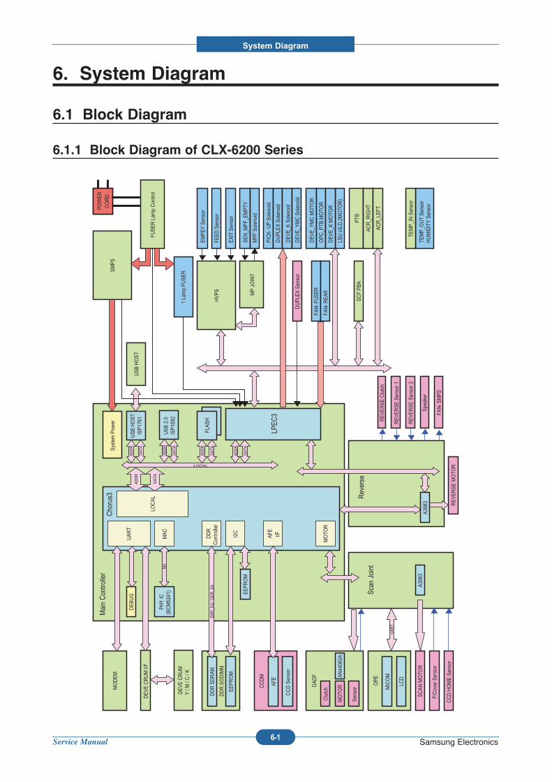
Service Manual
System Diagram
6-1 Samsung Electronics
Scan
Joint
CCDM
AFE
CCD Sensor
F/Cover Sensor
SCAN
MOTO
R
OPE
LCD
MICOM
DDR SODIMM
DDR SDRAM
EEPR
OM
Main Con
troller
Chorus3
DDR
Contro
ller
I2C
EEPR
OM
LOCAL
USB
2.0
ISP1
582
USB
HOST
ISP1
761
UAR
TDEB
UG
AFE
I/F
MOTO
R
FLAS
H
LPEC
3
System
Pow
er
DDR_D
Q / DDR_S
A
PHY IC
(BCM5241)
MAC
MII
DAD
F
Clutch
Sensor
MOTO
R
CCD HOME Se
nsor
REV
ERSE
Clutch
REV
ERSE
MOTO
R
ADDR
DAT
A
LOCAL
MODEM
ADDR
DAT
A
ADDR
DAT
A
ADDR
DAT
A
ADDR
DAT
A
Reverse
UAR
TREV
ERSE
Sensor 1
REV
ERSE
Sensor 2
A3983
AN44060A
A3983
USB
HOST
SMPS
FUSE
R Lam
p Contro
l
1 Lamp FU
SER
POWER
CORD
POWER
CORD
PTB
DEV
E CRUM I/F
HVP
S
MP JO
INT
LSU (4
LD,2MOTO
R)
TEMP_
OUT Se
nsor
HUMIDITY Se
nsor
DUPL
EX Sensor
SEN_M
PF_E
MPT
Y
MPF
Solenoid
EMPE
Y Se
nsor
EXIT Sensor
FEED
Sensor
DEV
E_YM
C MOTO
R
OPC
_PTB
MOTO
R
DEV
E_K MOTO
R
PICK-
UP So
lenoid
DUPL
EX Solenoid
DEV
E_K So
lenoid
DEV
E_YM
C Solenoid
FAN-
FUSE
R
ACR_R
IGHT
ACR_LEF
T
TEMP_
IN Sensor
DEV
E CRUM
Y / M
/ C / K
SCF PB
A
Speaker
FAN-
SMPS
FAN-
REA
R
6. System Diagram
6.1 Block Diagram
6.1.1 Block Diagram of CLX-6200 Series
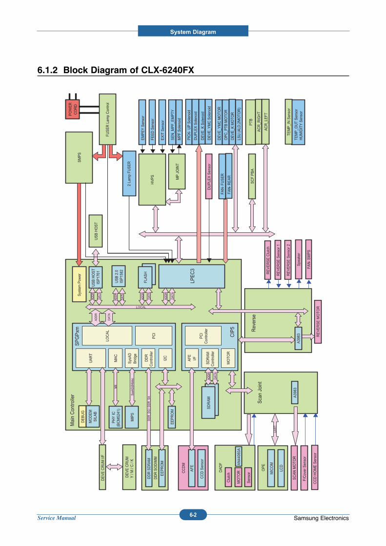
Service Manual
System Diagram
6-2 Samsung Electronics
6.1.2 Block Diagram of CLX-6240FX
Scan Joint
CCDM
AFE
CCD Sen
sor
F/Cover Sensor
SCAN MOTO
R
OPE
LCD
MICOM
DDR SODIMM
DDR SDRAM
EEPROM
Main Con
troller
SPGPxm
SysAD
Bridge
MIPS
DDR
Contro
ller
I2C
EEPROM
LOCAL
USB 2.0
ISP15
82
USB HOST
ISP1761
UART
PCI
DEBUG
CIP5
AFE I/F
PCI
Contro
ller
MOTO
R
SDRAM
Contro
ller
FLASH
SDRAM
LPEC3
System Pow
er
DDR_D
Q / DDR_S
A
PHY IC
(BCM5241)
MAC
MII
SysAD(64b
its)
DADF
Clutch
Sen
sor
MOTO
R
ADDR
DATA
CCD HOME Sensor
REVERSE Clutch
REVERSE MOTO
R
ADDR
DATA
LOCAL
MODEM
SILAB
ADDR
DATA
ADDR
DATA
ADDR
DATA
ADDR
DATA
Reverse
UART
REVERSE Sen
sor 1
REVERSE Sen
sor 2
A3983
AN44
060A
A39
83
USB HOST
SMPS
FUSER Lam
p Con
trol
2 La
mp FU
SER
POWER
CORD
POWER
CORD
PTB
DEVE CRUM I/F
HVPS
MP JOINT
LSU (4
LD,2MOTO
R)
TEMP_O
UT Sensor
HUMIDITY Sensor
DUPLE
X Sensor
SEN_M
PF_
EMPTY
MPF Solenoid
EMPEY Sensor
EXIT Sensor
FEED Sen
sor
DEVE_Y
MC MOTO
R
OPC_P
TB MOTO
R
DEVE_K
MOTO
R
PICK-
UP Solenoid
DUPLE
X Solen
oid
DEVE_K
Solen
oid
DEVE_Y
MC Solen
oid
FAN-
FUSER
ACR_R
IGHT
ACR_LEFT
TEMP_IN Sen
sor
DEVE CRUM
Y / M / C / K
SCF PBA
Speaker
FAN-
SMPS
FAN-
REAR
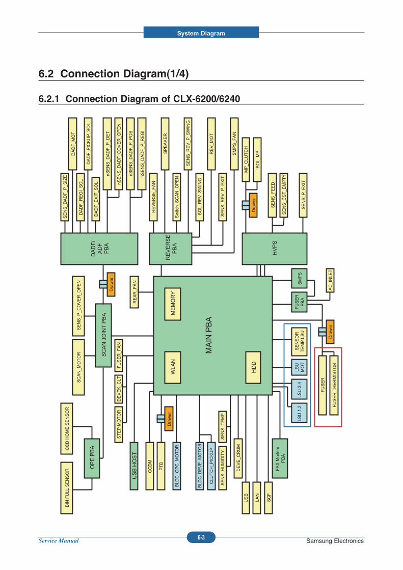
Service Manual
System Diagram
6-3 Samsung Electronics
6.2 Connection Diagram(1/4)
6.2.1 Connection Diagram of CLX-6200/6240
MAIN PBA
FAX Modem
PBA
FUSER
PBA
LSU 1,2
SMPS
REVERSE
PBA
HVPS
SCAN JOINT PBA
SCAN_M
OTOR
SENS_P
_COVER_O
PEN
DADF/
ADF
PBA
DADF_P
ICKUP_S
OL
DADF_E
XIT_S
OL
SENS_D
ADF_P
_SIZE
nSENS_D
ADF_C
OVER_O
PEN
DADF_R
EGI_SOL
nSENS_D
ADF_P
_DET
DADF_M
OT
Switch_SCAN_O
PEN
SENS_R
EV_P
_SWING
REV_M
OT
SPEAKER
SOL_REV_S
WING
REVERSE_FAN
SMPS_FAN
OPE PBA
BIN FULL SENSOR
CCD HOME SENSOR
PTB
MP_C
LUTCH
SOL_MP
HDD
BLD
C_O
PC_M
OTOR
DEVE_C
RUM
STEP MOTOR
CCDM
REAR_FAN
SENSOR
TEMP LSU
USB
LAN
SCF
LSU 3,4
SENS_FEED
SENS_C
ST_E
MPTY
USB HOST
SENS_R
EV_P
_EXIT
AC_INLE
T
Drawer
Drawer
FUSER THERMISTOR
MEMORY
FUSER
Drawer
LSU
MOT
DEVEK_C
LTFUSER_FAN
BLD
C_D
EVE_M
OTOR
CLU
TCH_P
ICKUP
SENS_TEMP
SENS_H
UMIDITY
WLA
N
Drawer
SENS_P
_EXIT
nSENS_D
ADF_P
_REGI
nSENS_D
ADF_P
_POS
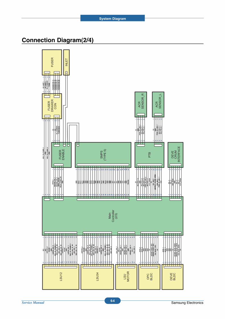
Service Manual
System Diagram
6-4 Samsung Electronics
Connection Diagram(2/4)
Main
Controller
(2/3)
LSU12
N.C
N.C
nHSYNC_2
5VLS
U
GND
1 2 3 4 5
12 34 56 7 8 9 10 11 12 13 14 15 17 1816
6 78 910 1112 1314 15 171816
nLDON_LSU_2
DAC_LD_P
OWER_0
VDO_LSU_2
P_1B
nSH_LSU_2
VDO_LSU_2
N_1B
nHSYNC_1
5VLS
U
GND
nLDON_LSU_1
DAC_LD_P
OWER_0
VDO_LSU_1P_1B
nSH_LSU_1
VDO_LSU_1N_1B
LSU12
N.C
N.C
nHSYNC_2
5VLS
U
GND
1 2 3 4 5
12 34 56 7 8 9 10 11 12 13 14 15 17 1816
6 78 910 1112 1314 15 171816
nLDON_LSU_2
DAC_LD_P
OWER_0
VDO_LSU_2
P_1B
nSH_LSU_2
VDO_LSU_2
N_1B
nHSYNC_1
5VLS
U
GND
nLDON_LSU_1
DAC_LD_P
OWER_0
VDO_LSU_1P_1B
nSH_LSU_1
VDO_LSU_1N_1B
LSU34
nHSYNC_4
5VLS
U
GND
nLDON_LSU_4
VDO_LSU_4P_1B
1 2 3 4 5
12 34 56 7 8 9 10 11 12 13 14 15 16
6 78 910 1112 1314 1516
DAC_LD_P
OWER_1
VDO_LSU_4N_1B
nSH_LSU_4
nHSYNC_3
5VLS
UnLDON_LSU_3
GND
DAC_LD_P
OWER_1
VDO_LSU_3P_1B
VDO_LSU_3N_1B
nSH_LSU_3
LSU34
nHSYNC_4
5VLS
U
GND
nLDON_LSU_4
VDO_LSU_4P_1B
1 2 3 4 5
12 34 56 7 8 9 10 11 12 13 14 15 16
6 78 910 1112 1314 1516
DAC_LD_P
OWER_1
VDO_LSU_4N_1B
nSH_LSU_4
nHSYNC_3
5VLS
UnLDON_LSU_3
GND
DAC_LD_P
OWER_1
VDO_LSU_3P_1B
VDO_LSU_3N_1B
nSH_LSU_3
LSU
MOTOR
CLK
_LSU_1
24V_1
nREADY_LSU_1
GND
nSTART_LSU_1
1 2 3 4 5
12 34 56 7 8 9 10
6 78 910
nSTART_LSU_4
GND
nREADY_LSU_4
24V_1
CLK
_LSU_4
LSU
MOTOR
CLK
_LSU_1
24V_1
nREADY_LSU_1
GND
nSTART_LSU_1
1 2 3 4 5
12 34 56 7 8 9 10
6 78 910
nSTART_LSU_4
GND
nREADY_LSU_4
24V_1
CLK
_LSU_4
OPC
BLD
C
24VS_2
24VS_2
GND
GND
GND
1 2 3 4 5
1 2 3 4 5
6 7 8 9 10
6 7 8 9 10
5V
nSTART_B
LDC_O
PC
nREADY_B
LDC_O
PC
CLK
_BLD
C_O
PC
5V
OPC
BLD
C
24VS_2
24VS_2
GND
GND
GND
1 2 3 4 5
1 2 3 4 5
6 7 8 9 10
6 7 8 9 10
5V
nSTART_B
LDC_O
PC
nREADY_B
LDC_O
PC
CLK
_BLD
C_O
PC
5V
DEVE
BLD
C
24VS_1
24VS_1
GND
GND
GND
1 2 3 4 5
1 2 3 4 5
6 7 8 9 10
6 7 8 9 10
5V
nSTART_B
LDC_D
EVE
nREADY_B
LDC_D
EVE
CLK
_BLD
C_D
EVE
5V
DEVE
BLD
C
24VS_1
24VS_1
GND
GND
GND
1 2 3 4 5
1 2 3 4 5
6 7 8 9 10
6 7 8 9 10
5V
nSTART_B
LDC_D
EVE
nREADY_B
LDC_D
EVE
CLK
_BLD
C_D
EVE
5V
FUSER
ENABLE
24VS_2
HEATER_O
N_1
HEATER_O
N_2
ZERO_C
ROSS
RELA
Y_F
USE_O
N
1 2 3 4 5
1 2 3 4 5
66
GND
FUSER
ENABLE
24VS_2
HEATER_O
N_1
HEATER_O
N_2
ZERO_C
ROSS
RELA
Y_F
USE_O
N
1 2 3 4 5
1 2 3 4 5
66
GND
FUSER
DRAWER
CON
ADC_T
H_F
USER_1
GND
ADC_T
H_F
USER_2
GND
1 2 3 4
1 2 3 4
AC
AC
AC_C
OMMON
FUSER BIAS
1 2 3 4
1 2 3 4
FUSER
DRAWER
CON
ADC_T
H_F
USER_1
GND
ADC_T
H_F
USER_2
GND
1 2 3 4
1 2 3 4
AC
AC
AC_C
OMMON
FUSER BIAS
1 2 3 4
1 2 3 4
FUSER
AC LAMP 1
AC LAMP 2
AC_C
OMMON
FGND
1 2 3 4
1 2 3 4
THERMISTOR 1B
THERMISTOR 1A
THERMISTOR 2B
THERMISTOR 2A
FUSER
AC LAMP 1
AC LAMP 2
AC_C
OMMON
FGND
1 2 3 4
1 2 3 4
THERMISTOR 1B
THERMISTOR 1A
THERMISTOR 2B
THERMISTOR 2A
PTB
5V
AN_C
TD_P
_2
GND
AN_C
TD_S
_2
AN_C
TD_P
_1
1 2 3 4 5
1 2 3 4 5
6 7 8 9 10 11 12 13 14
6 7 8 9 10 11 12 13 14
PWM_C
R_LED_2
AN_C
TD_S
_1
3.3V_C
RUM
5V
SCL_BELT
nDETECT_C
OVER_O
PEN
SDA_B
ELT
PWM_C
R_LED_1
5VS
PTB
5V
AN_C
TD_P
_2
GND
AN_C
TD_S
_2
AN_C
TD_P
_1
1 2 3 4 5
1 2 3 4 5
6 7 8 9 10 11 12 13 14
6 7 8 9 10 11 12 13 14
PWM_C
R_LED_2
AN_C
TD_S
_1
3.3V_C
RUM
5V
SCL_BELT
nDETECT_C
OVER_O
PEN
SDA_B
ELT
PWM_C
R_LED_1
5VS
ACR
SENSOR_R
5V
GND
PWM_C
R_LED_1
AN_C
TD_P
_1
1 2 3 4 5
1 2 3 4 5AN_C
TD_S
_1
ACR
SENSOR_R
5V
GND
PWM_C
R_LED_1
AN_C
TD_P
_1
1 2 3 4 5
1 2 3 4 5AN_C
TD_S
_1
ACR
SENSOR_L
5V
GND
PWM_C
R_LED_1
AN_C
TD_P
_1
1 2 3 4 5
1 2 3 4 5AN_C
TD_S
_1
ACR
SENSOR_L
5V
GND
PWM_C
R_LED_1
AN_C
TD_P
_1
1 2 3 4 5
1 2 3 4 5AN_C
TD_S
_1
DEVE
CRUM
INTERFACE
SCL_4
SCL_3
SDA_D
EVE
GND
SCL_2
1 2 3 4 5
1 2 3 4 5
6 7
6 7
SCL_1
3.3V_C
RUM
DEVE
CRUM
INTERFACE
SCL_4
SCL_3
SDA_D
EVE
GND
SCL_2
1 2 3 4 5
1 2 3 4 5
6 7
6 7
SCL_1
3.3V_C
RUM
SMPS
(TYPE 5)
24V1
GND
24V1
24V1
GND
1 2 3 4 5
12 34 56 7 8 9 10 11 12 13 14 15 17 18 19 20 21 22 23 2416
6 78 910 1112 1314 15 1718 1920 2122 232416
GND
24V2
GND
24V2
24V2
GND
GND
24V3
GND
24V3
GND
GND
GND
5V1
GND
5V1
5V1
GND
GND
26 27 28
5V2
Standby
GND
2526 272825
5V2
SMPS
(TYPE 5)
24V1
GND
24V1
24V1
GND
1 2 3 4 5
12 34 56 7 8 9 10 11 12 13 14 15 17 18 19 20 21 22 23 2416
6 78 910 1112 1314 15 1718 1920 2122 232416
GND
24V2
GND
24V2
24V2
GND
GND
24V3
GND
24V3
GND
GND
GND
5V1
GND
5V1
5V1
GND
GND
26 27 28
5V2
Standby
GND
2526 272825
5V2
INLE
TINLE
T
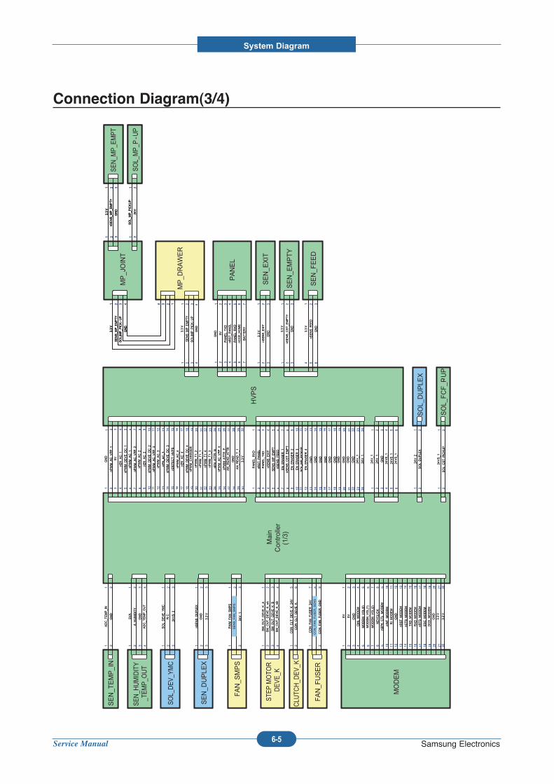
Service Manual
System Diagram
6-5 Samsung Electronics
Connection Diagram(3/4)
Main
Con
troller
(1/3)
SM_O
UT_D
EVE_K
_ASM_O
UT_D
EVE_K
_nA
SM_O
UT_D
EVE_K
_BSM_O
UT_D
EVE_K
_nB
1 2 3 4
1 2 3 4
CON_C
LT_D
EVE_K
_24V
15
26
CON_C
LT_D
EVE_K
1 2
7 8 9
CON_F
AN_F
USER_2
4VCON_F
AN_F
USER_S
ENS
CON_F
AN_F
USER_G
ND
FAN_F
USER
CLU
TCH_D
EV_K
STE
P MOTO
R
DEVE_K
SM_O
UT_D
EVE_K
_ASM_O
UT_D
EVE_K
_nA
SM_O
UT_D
EVE_K
_BSM_O
UT_D
EVE_K
_nB
1 2 3 4
1 2 3 4
CON_C
LT_D
EVE_K
_24V
15
26
CON_C
LT_D
EVE_K
1 2
7 8 9
CON_F
AN_F
USER_2
4VCON_F
AN_F
USER_S
ENS
CON_F
AN_F
USER_G
ND
PWM_F
AN_S
MPS
SENS_F
AN_S
MPS
1 2
1
24V_1
32
FAN_S
MPS
PWM_F
AN_S
MPS
SENS_F
AN_S
MPS
1 2
1
24V_1
32
GND
nPWM_A
C_V
PP_1
5V
nEN_A
C_1
nPWM_D
EVE_D
C_1
1 2 3 4 5
1 2 3 4 5
6 7 8 9 10 11 12 13 14 15 17 18 19 20 21 22 23 2416
6 7 8 9 10 11 12 13 14 15 17 18 19 20 21 22 23 2416
nPWM_A
C_1
nPWM_A
C_V
PP_2
nPWM_A
C_2
nEN_A
C_2
nPWM_D
EVE_D
C_2
nPWM_A
C_V
PP_3
nPWM_A
C_3
nEN_A
C_3
nPWM_D
EVE_D
C_3
nDETECT_H
VPS
nPWM_A
C_4
nEN_A
C_4
nPWM_D
EVE_D
C_4
nPWM_C
HARGER
nPWM_T
1_2
nPWM_T
1_1
nPWM_T
1_4
nPWM_T
1_3
nEN_A
TTR_N
26 27 28 29 30
nPWM_A
TTR_P
AN_R
EAD_A
TTR
GND
AN_R
EAD_T
_1
3.3V
nPWM_A
C_V
PP_4
25
26 27 28 29 3025
PANEL_
RXD
nRST_P
ANEL
PANEL_
TXD
nSENS_E
XIT
SENS_M
P_E
MPT
1 2 3 4 5
1 2 3 4 5
6 7 8 9 10 11 12 13 14 15 17 18 19 20 21 22 23 2416
6 7 8 9 10 11 12 13 14 15 17 18 19 20 21 22 23 2416
nSENS_F
EED
EN_E
RASER_1
nSENS_C
ST_E
MPT
EN_E
RASER_2
EN_E
RASER_3
SOL_
MP_P
ICKUP
EN_E
RASER_4
GND
GND
GND
GND
GND
GND
GND
GND
GND
GND
24V_1
24V_1
24V_1
24V_1
GND
24VS_1
24VS_1
1 2 3 4 5
1 2 3 4 5
66
24VS_1
HVPS
GND
nPWM_A
C_V
PP_1
5V
nEN_A
C_1
nPWM_D
EVE_D
C_1
1 2 3 4 5
1 2 3 4 5
6 7 8 9 10 11 12 13 14 15 17 18 19 20 21 22 23 2416
6 7 8 9 10 11 12 13 14 15 17 18 19 20 21 22 23 2416
nPWM_A
C_1
nPWM_A
C_V
PP_2
nPWM_A
C_2
nEN_A
C_2
nPWM_D
EVE_D
C_2
nPWM_A
C_V
PP_3
nPWM_A
C_3
nEN_A
C_3
nPWM_D
EVE_D
C_3
nDETECT_H
VPS
nPWM_A
C_4
nEN_A
C_4
nPWM_D
EVE_D
C_4
nPWM_C
HARGER
nPWM_T
1_2
nPWM_T
1_1
nPWM_T
1_4
nPWM_T
1_3
nEN_A
TTR_N
26 27 28 29 30
nPWM_A
TTR_P
AN_R
EAD_A
TTR
GND
AN_R
EAD_T
_1
3.3V
nPWM_A
C_V
PP_4
25
26 27 28 29 3025
PANEL_
RXD
nRST_P
ANEL
PANEL_
TXD
nSENS_E
XIT
SENS_M
P_E
MPT
1 2 3 4 5
1 2 3 4 5
6 7 8 9 10 11 12 13 14 15 17 18 19 20 21 22 23 2416
6 7 8 9 10 11 12 13 14 15 17 18 19 20 21 22 23 2416
nSENS_F
EED
EN_E
RASER_1
nSENS_C
ST_E
MPT
EN_E
RASER_2
EN_E
RASER_3
SOL_
MP_P
ICKUP
EN_E
RASER_4
GND
GND
GND
GND
GND
GND
GND
GND
GND
GND
24V_1
24V_1
24V_1
24V_1
GND
24VS_1
24VS_1
1 2 3 4 5
1 2 3 4 5
66
24VS_1
SEN_E
XIT
3.3V
nSENS_E
XIT
GND
1 2 3
1 2 3SEN_E
XIT
3.3V
nSENS_E
XIT
GND
1 2 3
1 2 3
SEN_E
MPTY
3.3V
nSENS_C
ST_E
MPTY
GND
1 2 3
1 2 3
SEN_F
EED
3.3V
nSENS_F
EED
GND
4 5 6
1 2 3
SEN_E
MPTY
3.3V
nSENS_C
ST_E
MPTY
GND
1 2 3
1 2 3
SEN_F
EED
3.3V
nSENS_F
EED
GND
4 5 6
1 2 3
MP_JOINT
MP_D
RAWER
3.3V
SENS_M
P_E
MPTY
SOL)MP_P
ICK-UP
1 2 3
1 2 34
4GND
3.3V
SENS_M
P_E
MPTY
SOL)MP_P
ICK-UP
1 2 3 1234 4
GND
1 2 3
1 2 3
3.3V
nSENS_M
P_E
MPTY
GND
SOL_
MP_P-U
PSOL_
MP_P
ICKUP
24V
1 21 2
MP_JOINT
MP_D
RAWER
3.3V
SENS_M
P_E
MPTY
SOL)MP_P
ICK-UP
1 2 3
1 2 34
4GND
3.3V
SENS_M
P_E
MPTY
SOL)MP_P
ICK-UP
1 2 3 1234 4
GND
3.3V
SENS_M
P_E
MPTY
SOL)MP_P
ICK-UP
1 2 3 1234 4
GND
1 2 3
1 2 3
3.3V
nSENS_M
P_E
MPTY
GND
SEN_M
P_E
MPT
1 2 3
1 2 3
3.3V
nSENS_M
P_E
MPTY
GND
-UP
SOL_
MP_P
ICKUP
24V
1 21 2
-UP
SOL_
MP_P
ICKUP
24V
1 21 2
PANEL
GND
5V
PANEL_
TXD
nRST_P
ANEL
PANEL_
RXD
1 2 3 4 5
1 2 3 4 5nC
CD_H
OME
BATTERY
6 7
6 7
PANEL
GND
5V
PANEL_
TXD
nRST_P
ANEL
PANEL_
RXD
1 2 3 4 5
1 2 3 4 5nC
CD_H
OME
BATTERY
6 7
6 7
SOL_
DEVE_Y
MC
N.C
1 2
1 2
24VS_2
33
SOL_DEV_Y
MC
SOL_
DEVE_Y
MC
N.C
1 2
1 2
24VS_2
33
SOL_
DUPLE
X24
V_2
SOL_
DUPLE
X1 2
1 2SOL_
DUPLE
X24
V_2
SOL_
DUPLE
X1 2
1 2
nSENS_D
UPLE
XGND
1 2
1 2
3.3V
33
SEN_D
UPLE
XnS
ENS_D
UPLE
XGND
1 2
1 2
3.3V
33
5VA
A_H
UMIDITY
1 2
1 2
GND
33
ADC_T
EMP_O
UT
44
SEN_H
UMIDITY
_TEMP_O
UT
5VA
A_H
UMIDITY
1 2
1 2
GND
33
ADC_T
EMP_O
UT
44
ADC_T
EMP_IN
GND
1 2
1 2SEN_T
EMP_IN
ADC_T
EMP_IN
GND
1 2
1 2
5V
5V
GND
CML_
MODEM
MODEM_V
OL(0)
1 2 3 4 5
1 2 3 4 5
6 7 8 9 10 11 12 13 14 15 17 18 19 20 21 2216
6 7 8 9 10 11 12 13 14 15 17 18 19 20 21 2216
MODEM_V
OL(1)
MODEM_V
OL(2)
KEYCLICK
nSPK_C
TL_
MODEM
nINT_M
ODEM
RI_MODEM
GND
nRST_M
ODEM
nCTS_M
ODEM
TXD_M
ODEM
RXD_M
ODEM
nRTS_M
ODEM
ESC_M
ODEM
DCD_M
ODEM
GND
3.3V
3.3V
MODEM
5V
5V
GND
CML_
MODEM
MODEM_V
OL(0)
1 2 3 4 5
1 2 3 4 5
6 7 8 9 10 11 12 13 14 15 17 18 19 20 21 2216
6 7 8 9 10 11 12 13 14 15 17 18 19 20 21 2216
MODEM_V
OL(1)
MODEM_V
OL(2)
KEYCLICK
nSPK_C
TL_
MODEM
nINT_M
ODEM
RI_MODEM
GND
nRST_M
ODEM
nCTS_M
ODEM
TXD_M
ODEM
RXD_M
ODEM
nRTS_M
ODEM
ESC_M
ODEM
DCD_M
ODEM
GND
3.3V
3.3V
SOL_
FCF_P-U
P24
VS_1
SOL_
CST_P
ICKUP
1 21 2
SOL_
FCF_P-U
P24
VS_1
SOL_
CST_P
ICKUP
1 21 2
SOL_MP_P
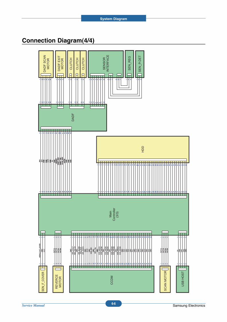
Service Manual
System Diagram
6-6 Samsung Electronics
Connection Diagram(4/4)
Main
Controller
(3/3)
nSENS_F
LAT_C
OVER
GND
1 2
1 2
3.3V
33
SEN_F
_COVER
nSENS_F
LAT_C
OVER
GND
1 2
1 2
3.3V
33
OUT1A
OUT1B
OUT2A
OUT2B
1 2 3 4
1 2 3 4
REVERCE
MOTOR
OUT1A
OUT1B
OUT2A
OUT2B
1 2 3 4
1 2 3 4
HDD
1 2 3 4 5 6 7 8 9 10 11 12 13 14 15 17 18 19 2016 21 22 23 24 25 26 27 28 29 30 31 32 33 34 35 37 38 39 4036
1 2 3 4 5 6 7 8 9 10 11 12 13 14 15 17 18 19 2016 21 22 23 24 25 26 27 28 29 30 31 32 33 34 35 37 38 39 4036
42 43 44
42 43 44
4141
HDD
1 2 3 4 5 6 7 8 9 10 11 12 13 14 15 17 18 19 2016 21 22 23 24 25 26 27 28 29 30 31 32 33 34 35 37 38 39 4036
1 2 3 4 5 6 7 8 9 10 11 12 13 14 15 17 18 19 2016 21 22 23 24 25 26 27 28 29 30 31 32 33 34 35 37 38 39 4036
42 43 44
42 43 44
4141
SCAN MOTOR
OUT1A
OUT1B
OUT2A
OUT2B
1 2 3 4
1 2 3 4SCAN MOTOR
OUT1A
OUT1B
OUT2A
OUT2B
1 2 3 4
1 2 3 4
USB HOST
5V
DM2
DP2
GND
GND
1 2 3 4 5
1 2 3 4 5
USB HOST
5V
DM2
DP2
GND
GND
1 2 3 4 5
1 2 3 4 5
GND
1 2 3 4 5 6 7 8 9 10 11 12 13 14 15 17 18 19 2016 21 22 23 24 25 26 27 28 29 30 31 32 33 34 35 37 38 39 4036
1 2 3 4 5 6 7 8 9 10 11 12 13 14 15 17 18 19 2016 21 22 23 24 25 26 27 28 29 30 31 32 33 34 35 37 38 39 4036
ADC_C
LK_P
ADC_C
LK_M
GND
AFE_S
LOAD
AFE_S
CLK
AFE_S
DATA
GND
24V2
GND
CCD_S
W1
GND
SIP5_
PItg
GND
CCD_A
DC(7)
CCD_A
DC(6)
GND
CCD_A
DC(5)
CCD_A
DC(4)
GND
CCD_A
DC(3)
CCD_A
DC(2)
GND
CCD_A
DC(1)
CCD_A
DC(0)
GND
5V3
GND
5V3
GND
N.C
GND
3.3V
GND
3.3V
GND
3.3V
GND
5V3
GND
CCDM
GND
1 2 3 4 5 6 7 8 9 10 11 12 13 14 15 17 18 19 2016 21 22 23 24 25 26 27 28 29 30 31 32 33 34 35 37 38 39 4036
1 2 3 4 5 6 7 8 9 10 11 12 13 14 15 17 18 19 2016 21 22 23 24 25 26 27 28 29 30 31 32 33 34 35 37 38 39 4036
ADC_C
LK_P
ADC_C
LK_M
GND
AFE_S
LOAD
AFE_S
CLK
AFE_S
DATA
GND
24V2
GND
CCD_S
W1
GND
SIP5_
PItg
GND
CCD_A
DC(7)
CCD_A
DC(6)
GND
CCD_A
DC(5)
CCD_A
DC(4)
GND
CCD_A
DC(3)
CCD_A
DC(2)
GND
CCD_A
DC(1)
CCD_A
DC(0)
GND
5V3
GND
5V3
GND
N.C
GND
3.3V
GND
3.3V
GND
3.3V
GND
5V3
GND
DADF
24V
24V
GND
GND
GND
1 2 3 4 5
12 34 56 7 8 9 10 11 12 13 14 15 16
6 78 910 1112 1314 1516
3.3V
GND
5V
DADF_R
XD
nRESET
SCAN_S
EN
GND
nSTOP
GND
GND
DADF_T
XD
DADF SCAN
MOTOR
1 2 3
1 2 3
4 5 6
4 5 6
DADF EXIT
MOTOR
1 2 3
1 2 3
44
SENSOR
INTERFACE
1 2 3
1 2 3
4 5 6
4 5 67 8
7 8
SEN_R
EG
123 1 2 3
SEN_P-D
ET
123 1 2 3
CLU
TCH
CLU
TCH
1 2 3
1 2
4
CLU
TCH
1 2 1 25 6
DADF
24V
24V
GND
GND
GND
1 2 3 4 5
12 34 56 7 8 9 10 11 12 13 14 15 16
6 78 910 1112 1314 1516
3.3V
GND
5V
DADF_R
XD
nRESET
SCAN_S
EN
GND
nSTOP
GND
GND
DADF_T
XD
DADF
24V
24V
GND
GND
GND
1 2 3 4 5
12 34 56 7 8 9 10 11 12 13 14 15 16
6 78 910 1112 1314 1516
3.3V
GND
5V
DADF_R
XD
nRESET
SCAN_S
EN
GND
nSTOP
GND
GND
DADF_T
XD
DADF SCAN
MOTOR
1 2 3
1 2 3
4 5 6
4 5 6
DADF SCAN
MOTOR
1 2 3
1 2 3
4 5 6
4 5 6
DADF EXIT
MOTOR
1 2 3
1 2 3
44
DADF EXIT
MOTOR
1 2 3
1 2 3
44
SENSOR
INTERFACE
1 2 3
1 2 3
4 5 6
4 5 67 8
7 8
SEN_R
EG
123 1 2 3
SEN_P-D
ET
123 1 2 3
SENSOR
INTERFACE
1 2 3
1 2 3
4 5 6
4 5 67 8
7 8
SEN_R
EG
123 1 2 3
SEN_P-D
ET
123 1 2 3
CLU
TCH
CLU
TCH
1 2 3
1 2
4
CLU
TCH
1 2 1 25 6
CLU
TCH
CLU
TCH
1 2 3
1 2
4
CLU
TCH
1 2 1 25 6
Service Manual
System Diagram
6-7 Samsung Electronics
6.3 Voltage Map(1/3)
SMPS
24V_1
24V_2
5V
Cover Open S/W
Relay
24VS_1
24VS_2
PTB S/W
5VS
FET
5VL
BEAD
5VLSU
BEAD
5VA
DC-DC
1.2V
BEAD
1.2V_DLL
BEAD
1.2V_PLL
DC-DC
1.3V
DDR POWER
VDDQ
VTT
DC-DC
3.3V_CPU
FILTER
VCPU
DC-DC
3.3V
FILTER
REGULATOR
1.8V
BEAD
3.3VA
BEAD
3.3V_DLL
BEAD
3.3V_ETH
BEAD
3.3V_CTR_TAP
FET
3.3V_CRUM
REGULATOR
1.8V_CIP5
Service Manual
System Diagram
6-8 Samsung Electronics
Voltage Map(2/3)
RESET
3.3V
SSCG (MCLK)
MIPS (RM7065C)
SPGPxm
M24C32
NOR FLASH
DDR SDRAM
DEBUG
USB DEVICE
LPEC3
SCF
SENSOR_DUPLEX
FUSER THERMISTOR
FUSER CONTROL
LSU I/F
MODEM
DADF
PLATEN MOTOR
PLATEN COVER SENSOR
USB HOST
CIP5
SDRAM (for CIP5)
CCD LVDS
CPLD
CCDM
VCPU
MIPS (RM7065C)
3.3V_DLL
SPGPxm
VDDQ
SPGPxm
DDR SDRAM
VTT
DDR SDRAM
3.3V_ETH
PHY
3.3V_CTR_TAP
RJ-45
3.3VA
LPEC3
3.3V_CRUM
MUX
S-CRUM
ANALO
G MUX
PTB I/F
FUSER THERMISTOR
BACK-UP
AFE

Service Manual
System Diagram
6-9 Samsung Electronics
Voltage Map(3/3)
DEBUG
5V
LSU
5VLS
U
HVPS I/F
OPE
HVPS
SENSOR_H
UMIDITY
5VA
PTB I/F
24V_1
LSU
24VS_2
FUSER CONTROL
24VS_1
BLD
C_D
EVE
BLD
C_O
PC
CLU
TCH_D
EVEK
STEP MOTOR_D
EVEK
SOLE
NOID_D
EVE_Y
MC
SOLE
NOID_F
CF_P
ICKUP
FAN_S
MPS
1.3V
MIPS (RM7065
C)
1.8V
LPEC3
1.2V
SPGPxm
1.2V_D
LLSPGPxm
1.2V_P
LLSPGPxm
24V_2
SCF
SOLE
NOID_D
UPLE
X
FAN_F
USER
MODEM
DADF
DADF
PLA
TEN MOTOR
USB HOST
CIP5
CIP5
CCD LAMP POWER
CCDM
CCDM
1.8V_C
IP5
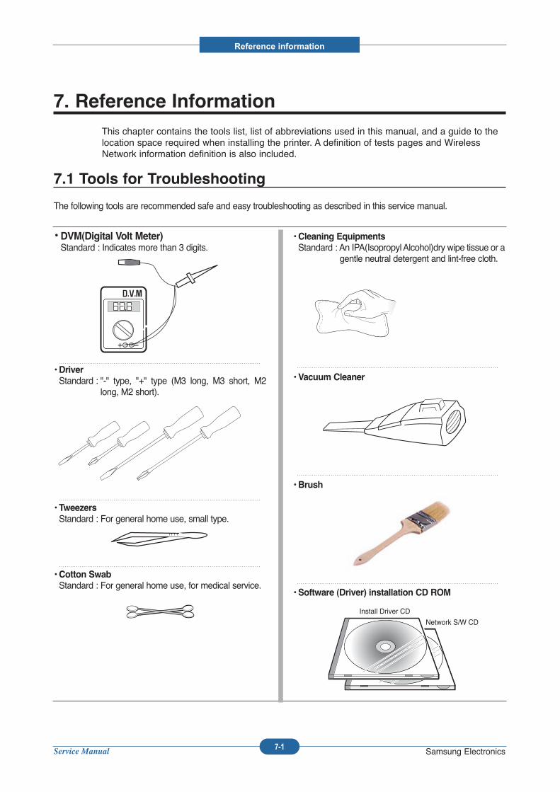
Service Manual
Reference information
7-1 Samsung Electronics
7. Reference Information
This chapter contains the tools list, list of abbreviations used in this manual, and a guide to thelocation space required when installing the printer. A definition of tests pages and WirelessNetwork information definition is also included.
7.1 Tools for Troubleshooting
The following tools are recommended safe and easy troubleshooting as described in this service manual.
• DVM(Digital Volt Meter)Standard : Indicates more than 3 digits.
• Driver
Standard : "-" type, "+" type (M3 long, M3 short, M2long, M2 short).
• Tweezers
Standard : For general home use, small type.
• Cotton Swab
Standard : For general home use, for medical service.
• Cleaning Equipments
Standard : An IPA(Isopropyl Alcohol)dry wipe tissue or agentle neutral detergent and lint-free cloth.
• Vacuum Cleaner
• Brush
• Software (Driver) installation CD ROM
Install Driver CD
Network S/W CD
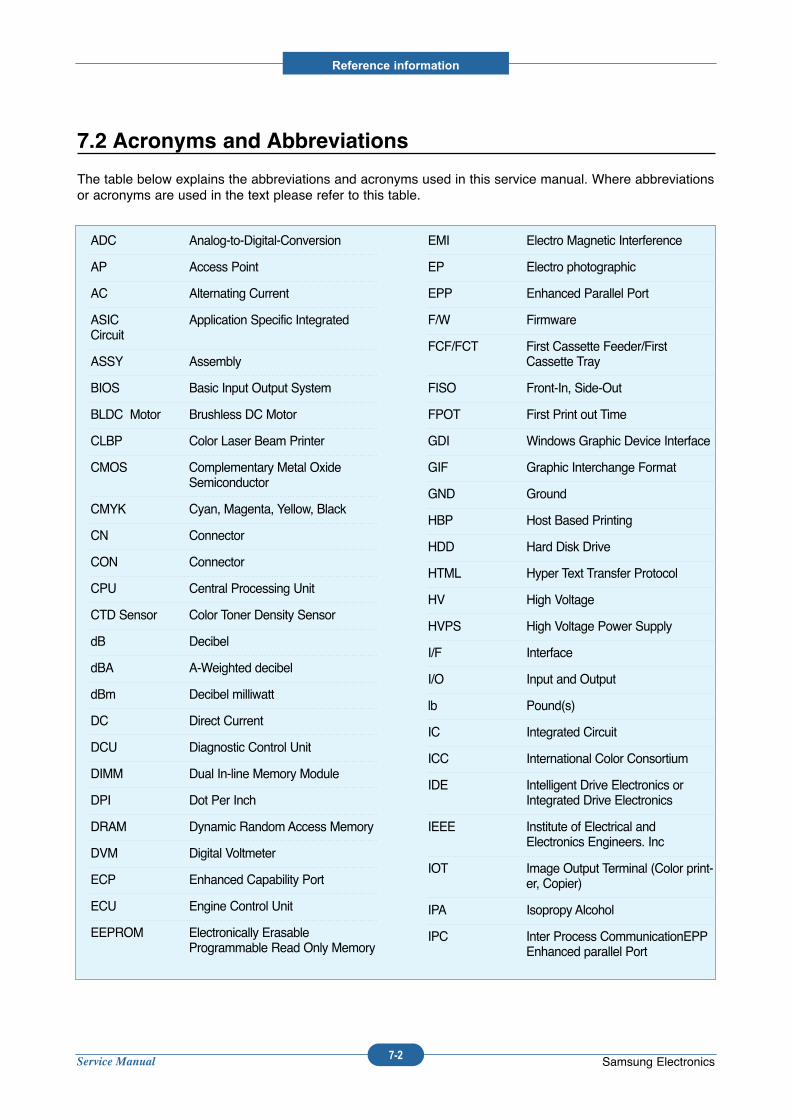
Service Manual
Reference information
7-2 Samsung Electronics
7.2 Acronyms and Abbreviations
The table below explains the abbreviations and acronyms used in this service manual. Where abbreviationsor acronyms are used in the text please refer to this table.
ADC Analog-to-Digital-Conversion
AP Access Point
AC Alternating Current
ASIC Application Specific IntegratedCircuit
ASSY Assembly
BIOS Basic Input Output System
BLDC Motor Brushless DC Motor
CLBP Color Laser Beam Printer
CMOS Complementary Metal OxideSemiconductor
CMYK Cyan, Magenta, Yellow, Black
CN Connector
CON Connector
CPU Central Processing Unit
CTD Sensor Color Toner Density Sensor
dB Decibel
dBA A-Weighted decibel
dBm Decibel milliwatt
DC Direct Current
DCU Diagnostic Control Unit
DIMM Dual In-line Memory Module
DPI Dot Per Inch
DRAM Dynamic Random Access Memory
DVM Digital Voltmeter
ECP Enhanced Capability Port
ECU Engine Control Unit
EEPROM Electronically ErasableProgrammable Read Only Memory
EMI Electro Magnetic Interference
EP Electro photographic
EPP Enhanced Parallel Port
F/W Firmware
FCF/FCT First Cassette Feeder/FirstCassette Tray
FISO Front-In, Side-Out
FPOT First Print out Time
GDI Windows Graphic Device Interface
GIF Graphic Interchange Format
GND Ground
HBP Host Based Printing
HDD Hard Disk Drive
HTML Hyper Text Transfer Protocol
HV High Voltage
HVPS High Voltage Power Supply
I/F Interface
I/O Input and Output
lb Pound(s)
IC Integrated Circuit
ICC International Color Consortium
IDE Intelligent Drive Electronics orIntegrated Drive Electronics
IEEE Institute of Electrical andElectronics Engineers. Inc
IOT Image Output Terminal (Color print-er, Copier)
IPA Isopropy Alcohol
IPC Inter Process CommunicationEPPEnhanced parallel Port
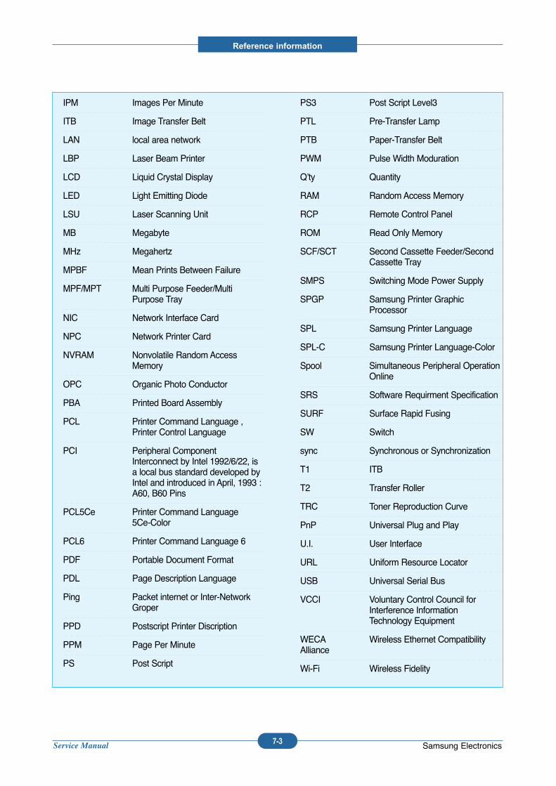
Service Manual
Reference information
7-3 Samsung Electronics
IPM Images Per Minute
ITB Image Transfer Belt
LAN local area network
LBP Laser Beam Printer
LCD Liquid Crystal Display
LED Light Emitting Diode
LSU Laser Scanning Unit
MB Megabyte
MHz Megahertz
MPBF Mean Prints Between Failure
MPF/MPT Multi Purpose Feeder/MultiPurpose Tray
NIC Network Interface Card
NPC Network Printer Card
NVRAM Nonvolatile Random AccessMemory
OPC Organic Photo Conductor
PBA Printed Board Assembly
PCL Printer Command Language ,Printer Control Language
PCI Peripheral ComponentInterconnect by Intel 1992/6/22, isa local bus standard developed byIntel and introduced in April, 1993 :A60, B60 Pins
PCL5Ce Printer Command Language 5Ce-Color
PCL6 Printer Command Language 6
PDF Portable Document Format
PDL Page Description Language
Ping Packet internet or Inter-NetworkGroper
PPD Postscript Printer Discription
PPM Page Per Minute
PS Post Script
PS3 Post Script Level3
PTL Pre-Transfer Lamp
PTB Paper-Transfer Belt
PWM Pulse Width Moduration
Q’ty Quantity
RAM Random Access Memory
RCP Remote Control Panel
ROM Read Only Memory
SCF/SCT Second Cassette Feeder/SecondCassette Tray
SMPS Switching Mode Power Supply
SPGP Samsung Printer GraphicProcessor
SPL Samsung Printer Language
SPL-C Samsung Printer Language-Color
Spool Simultaneous Peripheral OperationOnline
SRS Software Requirment Specification
SURF Surface Rapid Fusing
SW Switch
sync Synchronous or Synchronization
T1 ITB
T2 Transfer Roller
TRC Toner Reproduction Curve
PnP Universal Plug and Play
U.I. User Interface
URL Uniform Resource Locator
USB Universal Serial Bus
VCCI Voluntary Control Council forInterference InformationTechnology Equipment
WECA Wireless Ethernet CompatibilityAlliance
Wi-Fi Wireless Fidelity
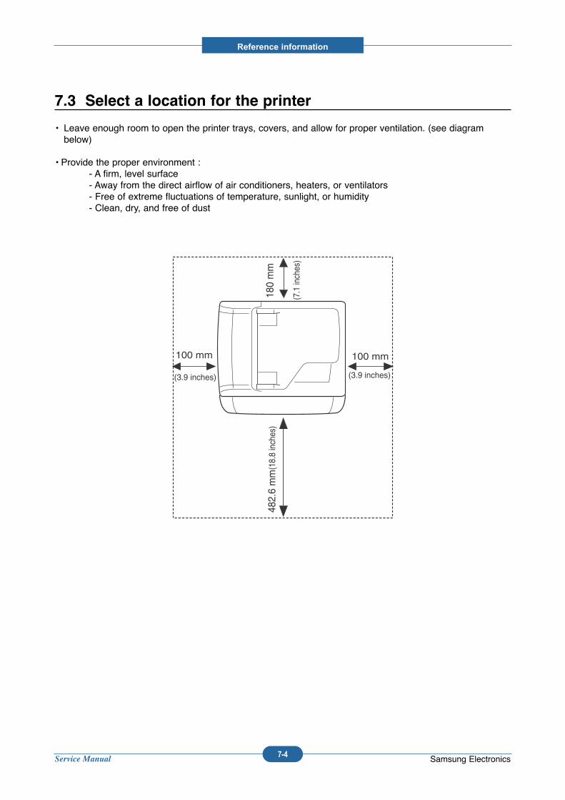
Service Manual
Reference information
7-4 Samsung Electronics
7.3 Select a location for the printer
• Leave enough room to open the printer trays, covers, and allow for proper ventilation. (see diagrambelow)
• Provide the proper environment :- A firm, level surface- Away from the direct airflow of air conditioners, heaters, or ventilators- Free of extreme fluctuations of temperature, sunlight, or humidity- Clean, dry, and free of dust
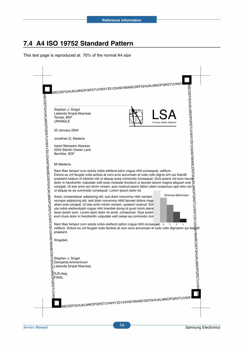
Service Manual
Reference information
7-5 Samsung Electronics
7.4 A4 ISO 19752 Standard Pattern
This test page is reproduced at 70% of the normal A4 size
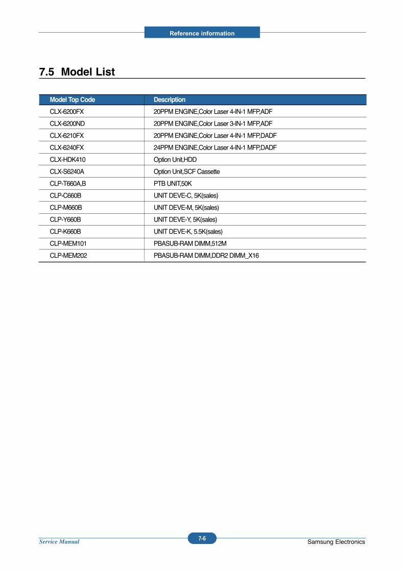
Service Manual
Reference information
7-6 Samsung Electronics
7.5 Model List
Model Top Code Description
CLX-6200FX 20PPM ENGINE,Color Laser 4-IN-1 MFP,ADF
CLX-6200ND 20PPM ENGINE,Color Laser 3-IN-1 MFP,ADF
CLX-6210FX 20PPM ENGINE,Color Laser 4-IN-1 MFP,DADF
CLX-6240FX 24PPM ENGINE,Color Laser 4-IN-1 MFP,DADF
CLX-HDK410 Option Unit,HDD
CLX-S6240A Option Unit,SCF Cassette
CLP-T660A,B PTB UNIT,50K
CLP-C660B UNITDEVE-C, 5K(sales)
CLP-M660B UNITDEVE-M, 5K(sales)
CLP-Y660B UNITDEVE-Y, 5K(sales)
CLP-K660B UNITDEVE-K, 5.5K(sales)
CLP-MEM101 PBASUB-RAM DIMM,512M
CLP-MEM202 PBASUB-RAM DIMM,DDR2 DIMM_X16
Related Documents
![Samsung CLX-9201 CLX-9251 CLX-9301 CLX-9206 CLX …ST] Samsung CLX... · Samsung CLX-9201 CLX-9251 CLX-9301 CLX-9206 ... CLX-9812 CLX-9813 SCX-8128 Multi-Function Printers ... Security](https://static.cupdf.com/doc/110x72/5aa6fa8f7f8b9ad31c8b5d51/samsung-clx-9201-clx-9251-clx-9301-clx-9206-clx-st-samsung-clxsamsung-clx-9201.jpg)