Pocket Guide to Watthour Meters Steve Hudson, P.E. VP of Hardware Engineering 10737 Lexington Drive Knoxville, TN 37932 Phone: (865) 966-5856 www.powermetrix.com

Welcome message from author
This document is posted to help you gain knowledge. Please leave a comment to let me know what you think about it! Share it to your friends and learn new things together.
Transcript

Pocket Guide to Watthour
Meters
Steve Hudson, P.E.
VP of Hardware Engineering
10737 Lexington Drive
Knoxville, TN 37932
Phone: (865) 966-5856
www.powermetrix.com

Overview of the Pocket Guide
• Chapter 1 – Electricity and Metering
Concepts
▪ Voltage, Current, Phase
▪ Power and Energy
▪ Useful Triangles
▪ The Electricity Meter
▪ Vectors
▪ Full Load Current
▪ Meter Sockets
▪ Instrument Transformers

Overview of the Pocket Guide
• Chapter 2 – Meter Connection
Diagrams
▪ Service Types
▪ Meter Form Selection
▪ Meter Connection Diagrams

Overview of the Pocket Guide
• Chapter 3 – Installing Meters
▪ Meter Checks

Page 1 – Units, Power, &
Energy

AC vs DC
• Direct Current (DC) – an electric current
that flows in one direction.(IEEE100)
• Alternating Current (AC) – an electric
current that reverses direction at regularly
recurring intervals of time. (IEEE100)

Ohm’s Law
Ohm’s Law:
Voltage = Resistance x Current
V (or E) = I x R OR I = V / R
Georg Simon Ohm
1789 - 1854

Power Law
Power Law for DC
Power (Watts) = Voltage x Current
P = V x I
Power Law for AC
Power = Voltage x Current x Power Factor
P = V x I x PF
More on PF in a few minutes!

Ohm’s Law Wheel

AC Theory Review – Sine Wave
)2( −= ftSinVV pk
= 0
rmsVVpk 2=
VVrms 120=
VVpk 169=
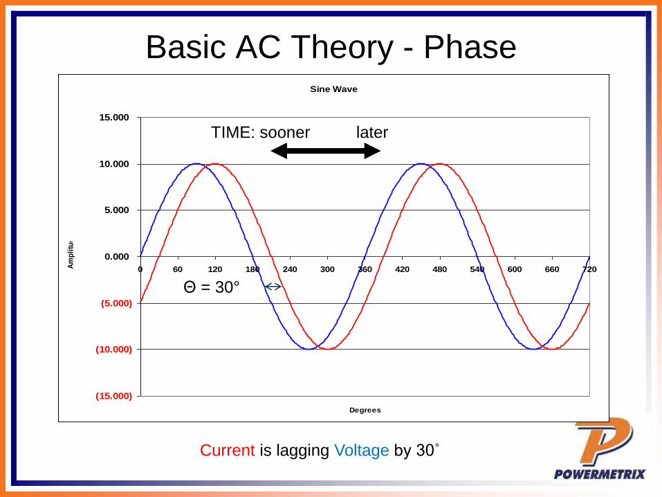
Basic AC Theory - PhaseSine Wave
(15.000)
(10.000)
(5.000)
0.000
5.000
10.000
15.000
0 60 120 180 240 300 360 420 480 540 600 660 720
Degrees
Am
pli
tud
e
Current is lagging Voltage by 30˚
Θ = 30°
TIME: sooner later

Basic AC TheoryPower – The Simple View
V = Voltage (RMS)
I = Current (RMS)
PF = Power Factor
Power = Watts = V x I x PF
Power is sometimes
referred to as Demand
Sinusoidal
Waveforms
Only
NO
Harmonics
For a 120 Volt service drawing
13 Amps at Unity (1.0) PF,
how much power is being drawn?
Power = 120 x 13 x 1.0 = 1560 Watts

Basic Meter MathPower – The Simple View
For a 120 Volt service drawing
13 Amps at 0.866 PF (Ɵ=30˚),
how much power is being drawn?
Power = 120 x 13 x 0.866 = 1351 Watts
For a 120 Volt service drawing
13 Amps at 0.5 PF (Ɵ=60˚),
how much power is being drawn?
Power = 120 x 13 x 0.5 = 780 Watts
Power = V x I x PF

Basic AC TheoryPower – The Simple View
For a 120 Volt service drawing
13 Amps at 0.866 PF,
how many Kilowatts are being drawn?
Power = 120 x 13 x 0.866 / 1000 = 1.351 kW
In the previous example we had:
Power = 120 x 13 x 0.866 = 1351 Watts
Normally we don’t talk about Watts, we speak in Kilowatts
1000 Watts = 1 Kilowatt = 1 kW
Watts / 1000 = Kilowatts

Basic AC TheoryEnergy – What We Sell
Energy = Power x Time
1 kW for 1 Hour = 1 Kilowatt-Hour = 1 kWh
If power is how fast water flows from a pipe,
then energy is how much water we have in a bucket
after the water has been flowing for a specified time.
Energy (Wh) = V x I x PF x T
Energy (kWh) = (V x I x PF / 1000) x T
where T = time in hours

Basic Meter MathEnergy – What We Sell
For a 120 Volt service drawing 45 Amps at a
Power Factor of 0.9 for 1 day,
how much Energy (kWh) has been used?
Energy = (120 x 45 x 0.9 / 1000) x 24 = 116.64 kWh
For a 240 Volt service drawing 60 Amps at a
Power Factor of 1.0 for 5.5 hours,
how much Energy (kWh) has been used?
Energy = (240 x 60 x 1.0 / 1000) x 5.5 = 79.2 kWh
Energy (kWh) = (V x I x PF / 1000) x T

Basic AC TheoryWhat is VA?
Power was measured in Watts. Power does useful work.
The power that does useful work is referred to as
“Active Power”.
VA is measured in Volt-Amperes. It is the capacity
required to deliver the Power. It is also referred to as the
“Apparent Power”.
Power Factor = Active Power / Apparent Power
VA = V x I
PF = W / VA

Basic Meter MathPower – VA
For a 120 Volt service drawing 13 Amps at 0.5 PF (60°)
Power = 120 x 13 x 0.5 = 780 Watts
How many VA are being drawn?
VA = 120 x 13 = 1560 Volt-Amperes
How much power is being drawn?

Basic Meter MathPower – VA
For a 120 Volt service drawing 13 Amps at 0.866 PF (30°)
Power = 120 x 13 x 0.866 = 1351 Watts
How many VA are being drawn?
VA = 120 x 13 = 1560 Volt-Amperes
How much power is being drawn?

Basic Meter MathPower – VA
For a 120 Volt service drawing 13 Amps at 1.0 PF (0°)
Power = 120 x 13 x 1.0 = 1560 Watts
How many VA are being drawn?
VA = 120 x 13 = 1560 Volt-Amperes
How much power is being drawn?

Phase
Angle
PF Watts VA
0 1.0 1560 W 1560 VA
30 0.866 1351 W 1560 VA
60 0.5 780 W 1560 VA
Power Factor, Watts, and VA
For our 120V, 13A system
As PF get closer to 1, the Watt value gets closer to
the VA value! This means more real power is being
consumed!
A table of PF vs phase angle values is on pages
18-19

Watt, VAR, and VA
Watt - useful power that does real work
at the load – light a bulb or turn a motor
VAR – non-useful power that is required
to drive the inductance or capacitance of
a power line
VA – the total power in the system; the
vector sum of Watts and VARs

Watt, VAR, and VA
VARs = Foam
(Non-Useful)
Watts = Liquid
(Useful)
VA =
Total
power

Where do VARs come from?
Inductance in the power transmission
line lower power factor and increases
VARs!

Power Factor Definition:
Power Factor represents the ratio
of active power (Watts) to the
total power (VA) in a system.
It is a representation of the
percentage of useful work being
done.

Phase
Angle
PF Watts VAR VA
0 1 1560 W 0 VAR 1560 VA
30 0.866 1351 W 780 VAR 1560 VA
60 0.5 780 W 1351 VAR 1560 VA
Power Factor, Watts, and
VARs
For a 120V, 13A System

Page 8 - Useful Triangles

Page 9 - Useful Triangles

Resistive Load
Sine Wave
-200
-150
-100
-50
0
50
100
150
200
0 60 120 180 240 300 360 420 480 540 600 660 720
Degrees
Am
pli
tud
e
AC RVrms
Irms
Resistors are measured in Ohms. When an AC voltage is applied to a resistor, the
current is in degrees. A resistive load is considered a “linear” load because when
the voltage is sinusoidal the current is sinusoidal.

Inductive Load
Sine Wave
-200
-150
-100
-50
0
50
100
150
200
0 60 120 180 240 300 360 420 480 540 600 660 720
Degrees
Am
pli
tud
e
Inductors are measured in Henries. When an AC voltage is applied to an inductor,
the current is 90 degrees out of phase. We say the current “lags” the voltage. A
inductive load is considered a “linear” load because when the voltage is sinusoidal
the current is sinusoidal.
AC LVrms
Irms

Capacitive Load
AC CVrms
Irms
Capacitors are measured in Farads. When an AC voltage is applied to a capacitor,
the current is 90 degrees out of phase. We say the current “leads” the voltage. A
capacitive load is considered a “linear” load because when the voltage is
sinusoidal the current is sinusoidal.
Sine Wave
-200
-150
-100
-50
0
50
100
150
200
0 60 120 180 240 300 360 420 480 540 600 660 720
Degrees
Am
pli
tud
e

Page 10 - Power Triangle(Sinusoidal Waveforms)

Page 10 - Power Triangle(Sinusoidal Waveforms)
If V = Sin(ωt) and I = Sin(ωt - θ) (the load is linear)
then
Active Power = VICos(θ) Watts
Reactive Power = VISin(θ) Volt-Amp Reactive (VAR)
Apparent Power = VI Volt-Amp (VA)
Watts
VA
Rs
θ

Power Factor Definition
Power Factor = Active / Apparent Power
= Watts / VA
= Cos(θ)
Power Factor can range from 1 to 0
Watts
VA
Rs
θ

Page 14 – Vector (Phasor)
Diagrams
Vectors and Phasors are the same thing!
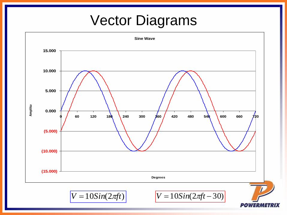
Vector DiagramsSine Wave
(15.000)
(10.000)
(5.000)
0.000
5.000
10.000
15.000
0 60 120 180 240 300 360 420 480 540 600 660 720
Degrees
Am
pli
tud
e
)2(10 ftSinV = )302(10 −= ftSinV
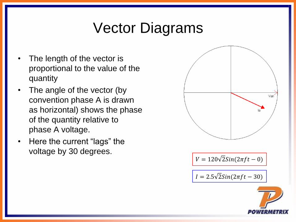
Vector Diagrams
• The length of the vector is
proportional to the value of the
quantity
• The angle of the vector (by
convention phase A is drawn
as horizontal) shows the phase
of the quantity relative to
phase A voltage.
• Here the current “lags” the
voltage by 30 degrees.
)02(2120 −= ftSinV
𝐼 = 2.5 2𝑆𝑖𝑛(2𝜋𝑓𝑡 − 30)
𝑉 = 120 2𝑆𝑖𝑛(2𝜋𝑓𝑡 − 0)

Vector Diagrams
• Vectors are particularly useful in poly-phase situations

Pages 20 – 21
Full Load Current
𝑆𝑖𝑛𝑔𝑙𝑒 𝑃ℎ𝑎𝑠𝑒 𝐹𝑢𝑙𝑙 𝐿𝑜𝑎𝑑 𝐶𝑢𝑟𝑟𝑒𝑛𝑡 =𝑐𝑖𝑟𝑐𝑢𝑖𝑡 𝑘𝑉𝐴 𝑥 10000
𝑐𝑖𝑟𝑐𝑢𝑖𝑡 𝑣𝑜𝑙𝑡𝑎𝑔𝑒
3 𝑃ℎ𝑎𝑠𝑒 𝐹𝑢𝑙𝑙 𝐿𝑜𝑎𝑑 𝐶𝑢𝑟𝑟𝑒𝑛𝑡 =𝑘𝑉𝐴 𝑥 10000
1.732 𝑥 𝑣𝑜𝑙𝑡𝑎𝑔𝑒 (𝐿 − 𝐿)
Full load Current Tables are given for
standard size distribution transformers on
pages 20 - 21

Page 85 – Allowable Ampacity

Page 22 – Meter Bases

Page 23 – Meter Sockets
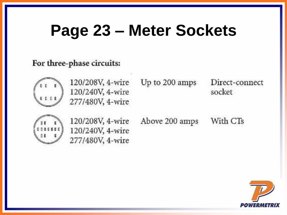
Page 23 – Meter Sockets

Page 25 – Meter Class

Page 25 – Meter Voltages

46
What is a Transformer?
• A TRANSFORMER is a device used to change the voltage levels of electricity to facilitate the transfer of electricity from generating stations to customers. A step-up transformer increases the voltage while a step-down transformer decreases it. www.duquesnelight.com/understandingelectricityupdate/electricterms.html

47
Basic Transformer Theory
• Vp = primary voltage
• Ip = primary current
• Np = primary turns
• Pp = primary power
• Vs = secondary voltage
• Is = secondary current
• Ns = secondary turns
• Ps = secondary power
VpNp
NsVs =
IpNs
NpIs =
IsVsPsIpVpPp •==•=
This is true for an IDEAL transformer!

48
What is an
Instrument Transformer?
Instrument Transformers
convert signal levels from
dangerous (high voltage) or
inconvenient (high current,
or current at high voltage) to
levels appropriate for
metering.
There are two fundamental
types:
CT’s (Current Transformers)
PT’s (Potential Transformers)

Page 26 & 27
CTs and PTs (VTs)

Page 28
Transformer Rated Site

Page 29
Safety Tips

Page 29
Safety Tips

Meter Form Selection

Meter Form Selection

Page 30
Meter Form Designation

Page 31
Meter Form Designation
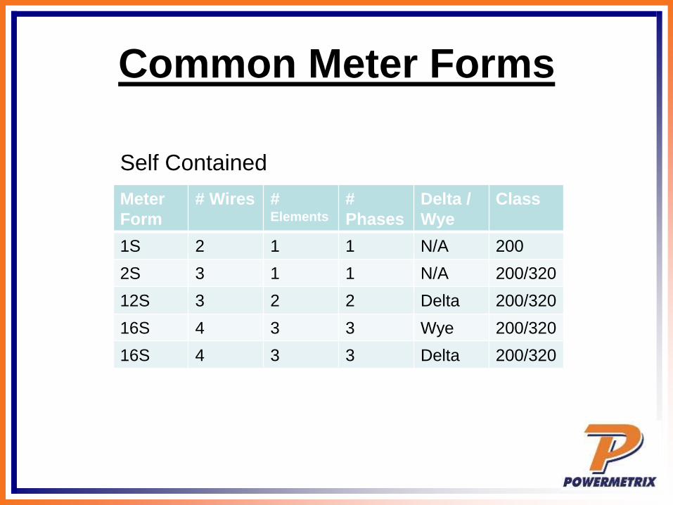
Common Meter Forms
Meter
Form
# Wires # Elements
#
Phases
Delta /
Wye
Class
1S 2 1 1 N/A 200
2S 3 1 1 N/A 200/320
12S 3 2 2 Delta 200/320
16S 4 3 3 Wye 200/320
16S 4 3 3 Delta 200/320
Self Contained

Common Meter Forms
Meter
Form
# Wires # Elements
#
Phases
Delta /
Wye
Class
3S 2 1 1 N/A 20
5S 3 or 4 2 3 Delta 20
6S 4 2.5 2 Wye 20
9S 4 3 3 Wye 20
Transformer Rated

Page 32
Distribution Circuit Symbols

Page 32
Distribution Circuit Symbols

Pages 33-34
Meter Diagram Symbols
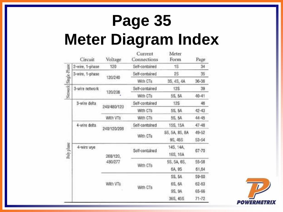
Page 35
Meter Diagram Index

Page 37
Form 2S – SC Single Phase 3W

Page 37
Form 2S – SC Single Phase 3W
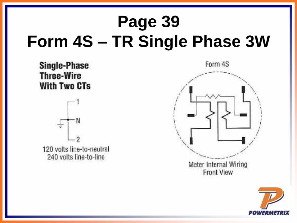
Page 39
Form 4S – TR Single Phase 3W

Page 39
Form 4S – TR Single Phase 3W

Page 41
Form 12S – SC 3W Network

Page 41
Form 12S – SC 3W Network

Page 42
Form 5S – TR 3W Network

Page 42
Form 5S – TR 3W Network

Page 48
Form 12S – SC 3WD

Page 48
Form 12S – SC 3WD
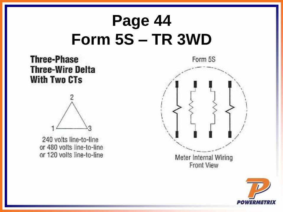
Page 44
Form 5S – TR 3WD
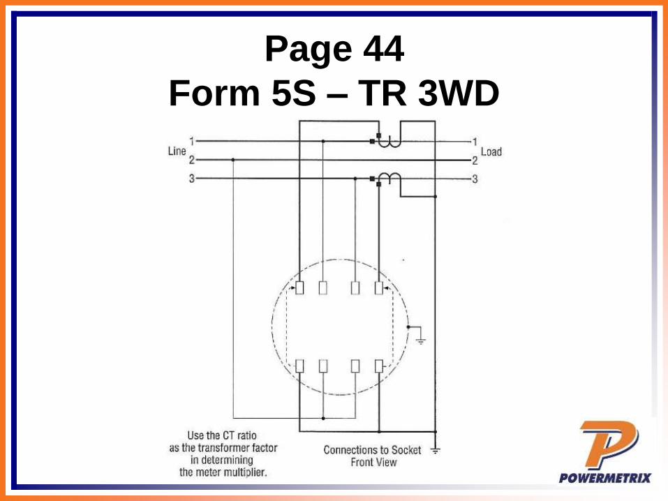
Page 44
Form 5S – TR 3WD

Page 71
Form 16S – SC 4WY

Page 71
Form 16S – SC 4WY

Page 67
Form 9S – TR 4WY

Page 67
Form 9S – TR 4WY

Page 87
Meter Socket Checks

Page 87
Meter Socket Checks

Page 89
Single Phase 3W Meter Check

Page 89
Single Phase 3W Meter Check

Questions? Comments?
Want a copy of this
presentation?
Go tohttps://www.powermetrix.com/presentations/
Thank you for your time!
Related Documents