CET Meter Catalogue CET Meter Catalogue CET Electric Technology Inc. Email: [email protected] Web: www.cet-global.com V.00 18.05.2022

Welcome message from author
This document is posted to help you gain knowledge. Please leave a comment to let me know what you think about it! Share it to your friends and learn new things together.
Transcript
CET Meter CatalogueCET Meter Catalogue
CET Electric Technology Inc.Email: [email protected]: www.cet-global.com V
.00
18
.05
.20
22

About CET
Founded in 1993
2 Production Bases
1000+ Employees
R&D Centres in Shenzhen and Wuhan
Market Presence in 10+ Countries
10+ Distributors
1 Design Institute
Big Data & Cloud Technologies
Accreditations
CET is a leading vendor of Energy Management Systems manufacturing high quality yet economical
monitoring solutions which include Digital Power and Energy Meters, PQ Monitors, as well as intelligent
Energy Management Systems that cater to a wide range of industries and applications since 1993.
Sales & Services
Email: [email protected]
Web: www.cet-global.com
facebook.com/CETInc.1993
twitter.com/CET_Inc
linkedin.com/company/cet-inc.
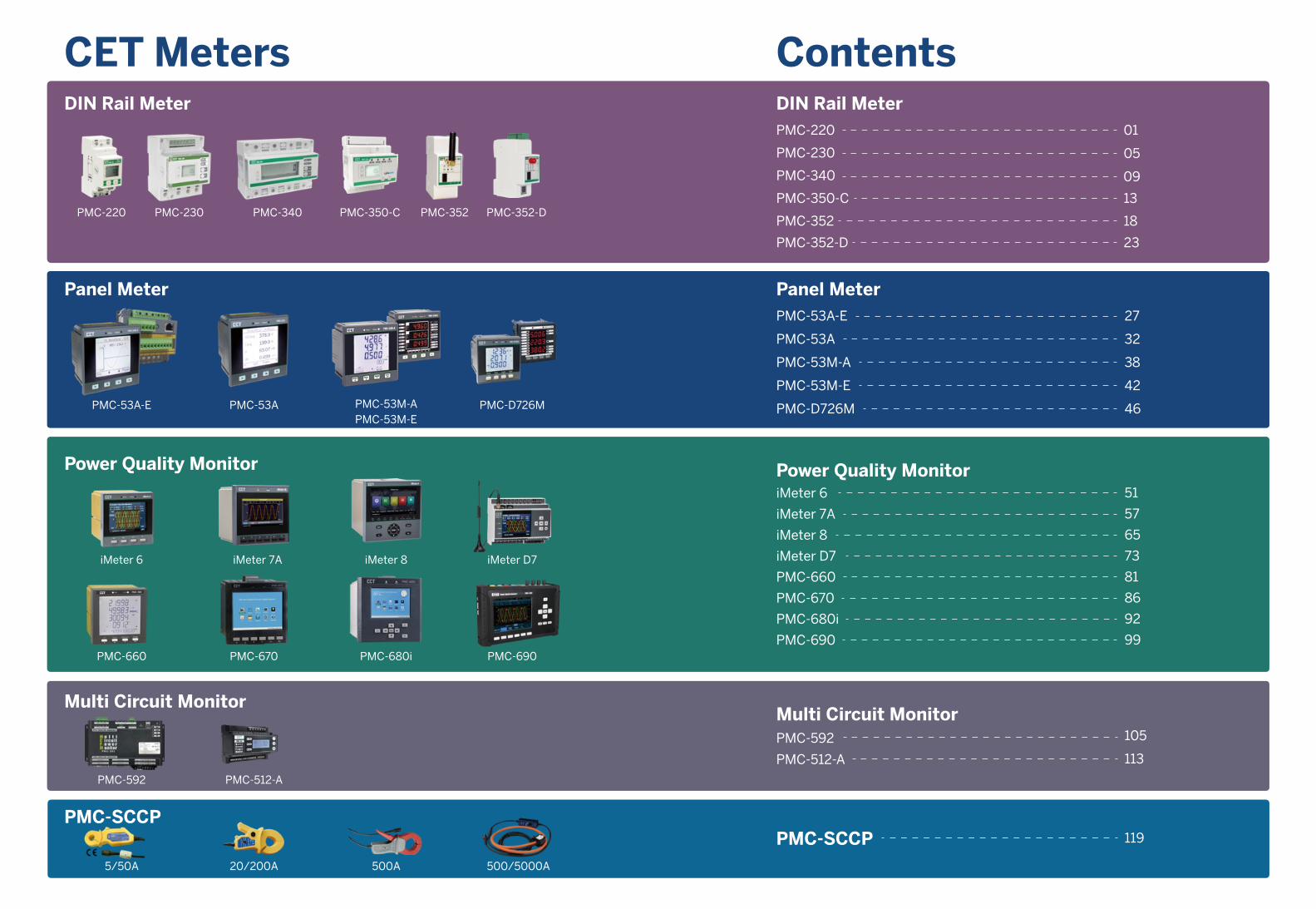
CET Meters Contents
Panel Meter
PMC-53A PMC-53M-APMC-53M-E
PMC-D726MPMC-53A-E
Panel MeterPMC-53A-E
PMC-53A
PMC-53M-A
PMC-53M-E
PMC-D726M
27
32
38
42
46
Power Quality Monitor
iMeter 6 iMeter 7A iMeter 8 iMeter D7
PMC-660 PMC-690PMC-670 PMC-680i
Power Quality MonitoriMeter 6
iMeter 7A
iMeter 8
iMeter D7
PMC-660
PMC-670
PMC-680i
PMC-690
51
57
65
73
81
86
92
99
Multi Circuit Monitor
PMC-592 PMC-512-A
Multi Circuit MonitorPMC-592
PMC-512-A
105
113
PMC-SCCP
500A 500/5000A5/50A 20/200A
PMC-SCCP 119
DIN Rail MeterPMC-220
PMC-230
PMC-340
PMC-350-C
PMC-352
01
05
13
18
09
PMC-352-D 23
DIN Rail Meter
PMC-340PMC-230 PMC-352 PMC-352-DPMC-350-CPMC-220
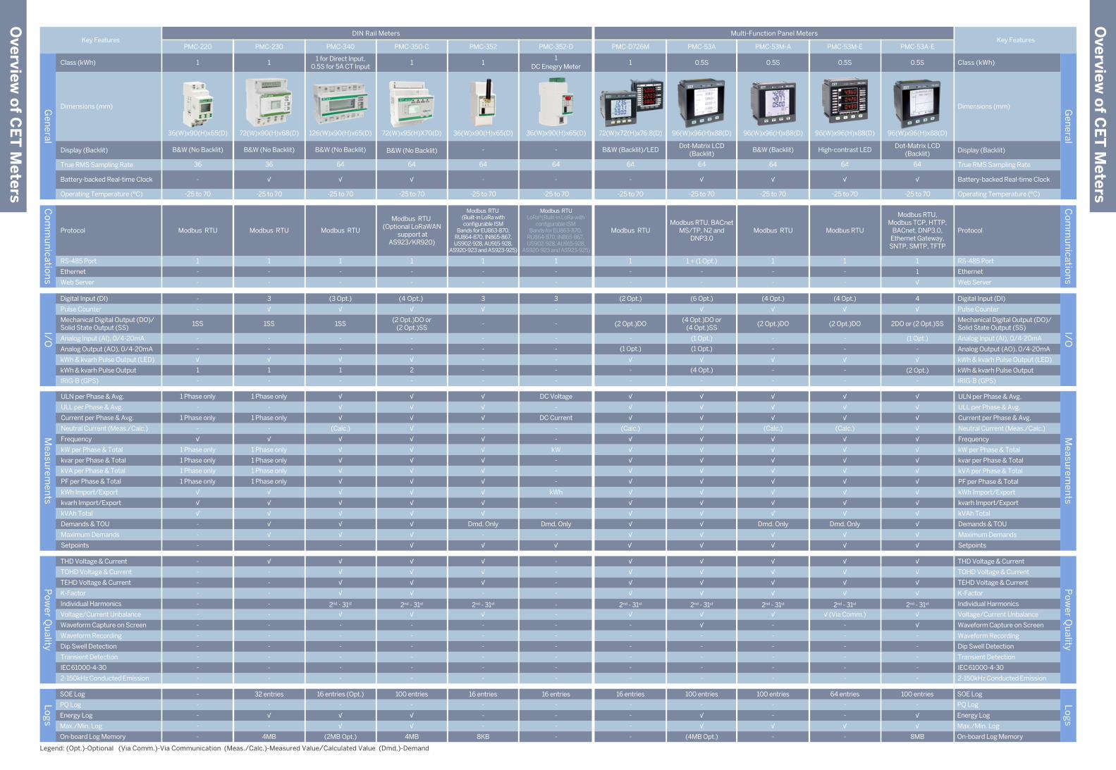
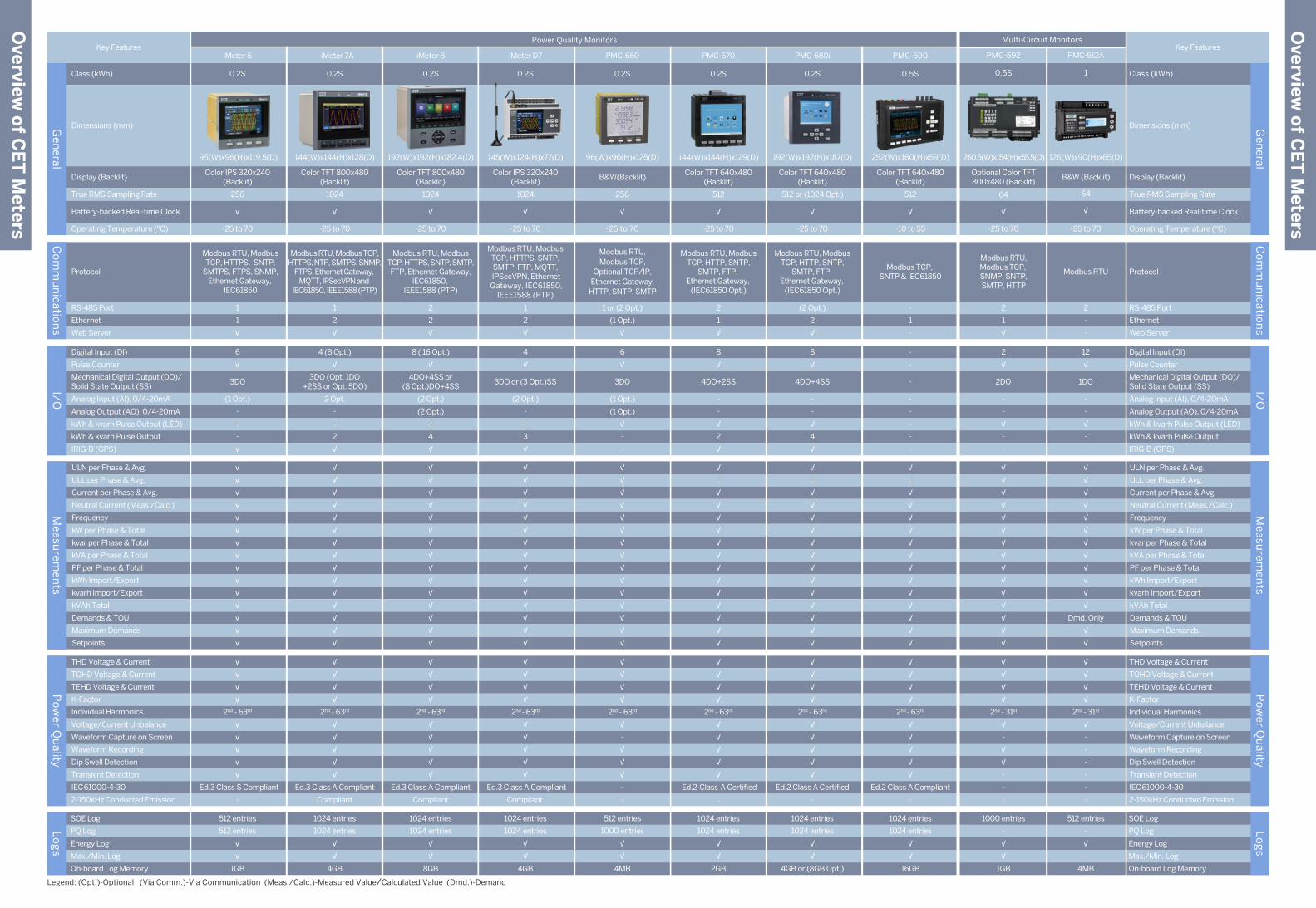
Key Features Key Features
Legend: (Opt.)-Optional (Via Comm.)-Via Communication (Meas./Calc.)-Measured Value/Calculated Value (Dmd.)-Demand
Display (Backlit)
True RMS Sampling Rate
Battery-backed Real-time Clock √
Display (Backlit)
True RMS Sampling Rate
Battery-backed Real-time Clock
Digital Input (DI)
Pulse Counter
Analog Input (AI), 0/4-20mA
Analog Output (AO), 0/4-20mA
kWh & kvarh Pulse Output (LED)
kWh & kvarh Pulse Output
IRIG-B (GPS)
Mechanical Digital Output (DO)/Solid State Output (SS)
-
-
-
√
√
-
Digital Input (DI)
Pulse Counter
Analog Input (AI), 0/4-20mA
Analog Output (AO), 0/4-20mA
kWh & kvarh Pulse Output (LED)
kWh & kvarh Pulse Output
IRIG-B (GPS)
Mechanical Digital Output (DO)/Solid State Output (SS)
-
Protocol
RS-485 Port
Web Server Web Server
Ethernet
1
-
Protocol
RS-485 Port
Ethernet
THD Voltage & Current
TOHD Voltage & Current
TEHD Voltage & Current
K-Factor
Individual Harmonics
Voltage/Current Unbalance
Waveform Capture on Screen
Waveform Recording
Dip Swell Detection
Transient Detection
√
√
√
√
-
-
-
-
THD Voltage & Current
TOHD Voltage & Current
TEHD Voltage & Current
K-Factor
Individual Harmonics
Voltage/Current Unbalance
Waveform Capture on Screen
Waveform Recording
Dip Swell Detection
Transient Detection
IEC 61000-4-30
2-150kHz Conducted Emission
-
-
IEC 61000-4-30
2-150kHz Conducted Emission
ULN per Phase & Avg.
ULL per Phase & Avg.
Current per Phase & Avg.
Neutral Current (Meas./Calc.)
Frequency
kW per Phase & Total
kvar per Phase & Total
kVA per Phase & Total
PF per Phase & Total
kWh Import/Export
kvarh Import/Export
kVAh Total
Demands & TOU
Maximum Demands
Setpoints
√
√
√
√
√
√
√
√
√
√
√
√
√
ULN per Phase & Avg.
ULL per Phase & Avg.
Current per Phase & Avg.
Neutral Current (Meas./Calc.)
Frequency
kW per Phase & Total
kvar per Phase & Total
kVA per Phase & Total
PF per Phase & Total
kWh Import/Export
kvarh Import/Export
kVAh Total
Demands & TOU
Maximum Demands
Setpoints
Overview
of C
ET
Meters
Overview
of C
ET
Meters
DIN Rail Meters
Class (kWh)
Dimensions (mm)
Multi-Function Panel Meters
Class (kWh)
Dimensions (mm)
SOE Log
PQ Log
Energy Log
Max./Min. Log
On-board Log Memory
-
-
√
-
SOE Log
PQ Log
Energy Log
Max./Min. Log
On-board Log Memory
Po
wer Q
uality
Gen
eralC
om
mu
nicatio
ns
I/OM
easurem
ents
Lo
gs
Gen
eralC
om
mu
nicatio
ns
I/OM
easurem
ents
Po
wer Q
uality
Lo
gs
B&W (No Backlit)
-
36
-
1SS
-
1
-
-
√
-
Modbus RTU
1
-
-
-
-
-
-
-
-
-
-
-
-
-
-
1 Phase only
1 Phase only
√
1 Phase only
1 Phase only
√
-
-
-
1 Phase only
1 Phase only
√
√
-
-
PMC-220
1
36(W)x90(H)x65(D)
-
-
-
-
-
-25 to 70
B&W (No Backlit)
√
36
3
1SS
-
1
-
√
√
-
Modbus RTU
1
-
-
√
-
-
-
-
-
-
-
-
-
-
-
1 Phase only
1 Phase only
√
1 Phase only
1 Phase only
√
√
-
-
-
1 Phase only
1 Phase only
√
√
√
PMC-230
1
72(W)x90(H)x68(D)
32 entries
-
√
-
4MB
-25 to 70
B&W (No Backlit)
√
64
1SS
-
1
-
√
√
-
(3 Opt.)
-
Modbus RTU
1
-
√
√
√
√
2nd - 31st
√
-
-
-
-
-
-
√
√
√
√
√
√
√
-
√
(Calc.)
√
√
√
√
√
PMC-340
1 for Direct Input,0.5S for 5A CT Input
126(W)x90(H)x65(D)
16 entries (Opt.)
-
√
√
(2MB Opt.)
-25 to 70Operating Temperature (ºC)
B&W (Backlit)/LED
-
64
(2 Opt.)
(2 Opt.)DO
(1 Opt.)
-
-
-
√
-
-
Modbus RTU
1
-
√
√
√
√
2nd - 31st
√
-
-
-
-
-
-
√
√
√
√
√
√
√
√
√
(Calc.)
√
√
√
√
√
PMC-D726M
1
72(W)x72(H)x76.8(D)
16 entries
-
-
-
-
-25 to 70
Dot-Matrix LCD(Backlit)
√
64
(6 Opt.)
(4 Opt.)DO or(4 Opt.)SS
(1 Opt.)
(4 Opt.)
(1 Opt.)
√
√
-
-
Modbus RTU, BACnetMS/TP, N2 and
DNP3.0
1 + (1 Opt.)
-
√
√
√
√
2nd - 31st
√
√
-
-
-
-
-
√
√
√
√
√
√
√
√
√
√
√
√
√
√
√
PMC-53A
0.5S
96(W)x96(H)x88(D)
100 entries
-
√
√
(4MB Opt.)
-25 to 70
High-contrast LED
64
(4 Opt.)
(2 Opt.)DO
Modbus RTU
2nd - 31st
√ (Via Comm.)
Dmd. Only
(Calc.)
PMC-53M-E
0.5S
96(W)x96(H)x88(D)
64 entries
-25 to 70
Dot-Matrix LCD(Backlit)
√
64
4
2DO or (2 Opt.)SS
-
(2 Opt.)
(1 Opt.)
√
√
-
√
Modbus RTU,Modbus TCP, HTTP,
BACnet, DNP3.0,Ethernet Gateway,SNTP, SMTP, TFTP
1
1
√
√
√
√
2nd - 31st
√
√
-
-
-
-
-
√
√
√
√
√
√
√
√
√
√
√
√
√
√
√
PMC-53A-E
0.5S
96(W)x96(H)x88(D)
100 entries
-
√
√
8MB
-25 to 70
B&W (Backlit)
√
64
(2 Opt.)DO
-
-
-
√
√
-
(4 Opt.)
-
Modbus RTU
1
-
√
√
√
√
2nd - 31st
√
-
-
-
-
-
-
√
√
√
√
√
√
Dmd. Only
√
√
(Calc.)
√
√
√
√
√
PMC-53M-A
0.5S
96(W)x96(H)x88(D)
100 entries
-
-
√
-
-25 to 70 Operating Temperature (ºC)
B&W (No Backlit)
√
64
(4 Opt.)
(2 Opt.)DO or(2 Opt.)SS
-
2
-
√
√
-
Modbus RTU (Optional LoRaWAN
support atAS923/KR920)
1
-
-
√
√
√
√
2nd - 31st
√
-
-
-
-
-
-
√
√
√
√
√
√
√
√
√
√
√
√
√
√
√
PMC-350-C
1
72(W)x95(H)X70(D)
100 entries
-
√
√
4MB
-25 to 70
-
-
64
3
-
-
-
-
√
-
-
3
-
-
-
-
-
-
-
Modbus RTU (Built-in LoRa withconfigurable ISM
Bands for EU863-870,RU864-870, IN865-867,US902-928, AU915-928,
AS920-923 and AS923-925)
Modbus RTULoRa*(Bulit-in LoRa with
configurable ISM Bands for EU863-870,
RU864-870, IN865-867, US902-928, AU915-928,
AS920-923 and AS923-925)
1
-
-
1
-
-
√
√
√
- -
2nd - 31st
√
-
-
-
-
-
-
-
-
-
-
-
-
-
-
-
-
-
√
√
√
√
√
√
Dmd. Only
√
√
-
√
√
√
√
-
DC Voltage
DC Current
-
-
-
-
Dmd. Only
√
-
-
kW
-
kWh
-
-
PMC-352 PMC-352-D
11
DC Enegry Meter
36(W)x90(H)x65(D)
16 entries
-
-
-
8KB
16 entries
-
-
-
-
36(W)x90(H)x65(D)
-25 to 70
-
-
64
-25 to 70
Operating Temperature (ºC) Operating Temperature (ºC)
Analog Output (AO), 0/4-20mA
Mechanical Digital Output (DO)/Solid State Output (SS)
Digital Input (DI)
Pulse Counter
Analog Input (AI), 0/4-20mA
kWh & kvarh Pulse Output (LED)
kWh & kvarh Pulse Output
IRIG-B (GPS)
Digital Input (DI)
Pulse Counter
Analog Input (AI), 0/4-20mA
Analog Output (AO), 0/4-20mA
kWh & kvarh Pulse Output (LED)
kWh & kvarh Pulse Output
IRIG-B (GPS)
Mechanical Digital Output (DO)/Solid State Output (SS)
THD Voltage & Current
TOHD Voltage & Current
TEHD Voltage & Current
K-Factor
Individual Harmonics
Voltage/Current Unbalance
Waveform Capture on Screen
Waveform Recording
Dip Swell Detection
Transient Detection
THD Voltage & Current
TOHD Voltage & Current
TEHD Voltage & Current
K-Factor
Individual Harmonics
Voltage/Current Unbalance
Waveform Capture on Screen
Waveform Recording
Dip Swell Detection
Transient Detection
IEC 61000-4-30
2-150kHz Conducted Emission
IEC 61000-4-30
2-150kHz Conducted Emission
ULN per Phase & Avg.
ULL per Phase & Avg.
Current per Phase & Avg.
Neutral Current (Meas./Calc.)
Frequency
kW per Phase & Total
kvar per Phase & Total
kVA per Phase & Total
PF per Phase & Total
kWh Import/Export
kvarh Import/Export
kVAh Total
Demands & TOU
Maximum Demands
Setpoints
ULN per Phase & Avg.
ULL per Phase & Avg.
Current per Phase & Avg.
Neutral Current (Meas./Calc.)
Frequency
kW per Phase & Total
kvar per Phase & Total
kVA per Phase & Total
PF per Phase & Total
kWh Import/Export
kvarh Import/Export
kVAh Total
Demands & TOU
Maximum Demands
Setpoints
SOE Log
Energy Log
Max./Min. Log
On-board Log Memory
PQ Log
SOE Log
PQ Log
Energy Log
Max./Min. Log
On-board Log Memory
Multi-Circuit Monitors
Overview
of C
ET
Meters
Overview
of C
ET
Meters
Legend: (Opt.)-Optional (Via Comm.)-Via Communication (Meas./Calc.)-Measured Value/Calculated Value (Dmd.)-Demand
Power Quality Monitors
Class (kWh)
Key Features Key Features
Dimensions (mm)
Display (Backlit)
True RMS Sampling Rate
Battery-backed Real-time Clock
Protocol
RS-485 Port
Web Server Web Server
Ethernet
Class (kWh)
Dimensions (mm)
Display (Backlit)
True RMS Sampling Rate
Battery-backed Real-time Clock
Protocol
RS-485 Port
Ethernet
Gen
eralC
om
mu
nicatio
ns
I/OM
easurem
ents
Po
wer Q
uality
Lo
gs
Gen
eralC
om
mu
nicatio
ns
I/OM
easurem
ents
Po
wer Q
uality
Lo
gs
-25 to 70
4DO+4SS or(8 Opt.)DO+4SS
(2 Opt.)
4
(2 Opt.)
√
√√
√
8 ( 16 Opt.)
√
√
√
√
2nd - 63rd
√
√
√
√
√
Ed.3 Class A Compliant
Compliant
√
√
√
√
√
√
√
√
√
√
√
√
√
√
√
1024 entries
1024 entries
√
√
8GB
0.2S
Color TFT 800x480(Backlit)
√
192(W)x192(H)x182.4(D)
1024
√
Modbus RTU, ModbusTCP, HTTPS, SNTP, SMTP,FTP, Ethernet Gateway,
IEC61850, IEEE1588 (PTP)
2
2
iMeter 8
-25 to 70
4
3DO or (3 Opt.)SS
-
3
(2 Opt.)
√
√
√
√
√
√
√
√
2nd - 63rd
√
√
√
√
√
Ed.3 Class A Compliant
Compliant
√
√
√
√
√
√
√
√
√
√
√
√
√
√
√
1024 entries
1024 entries
√
√
4GB
0.2S
Color IPS 320x240(Backlit)
√
145(W)x124(H)x77(D)
1024
Modbus RTU, Modbus TCP, HTTPS, SNTP, SMTP, FTP, MQTT, IPSecVPN, Ethernet
Gateway, IEC61850, IEEE1588 (PTP)
1
2
√
iMeter D7
6
3DO
(1 Opt.)
-
(1 Opt.)
√
√
-
√
√
√
√
√
-
√
√
√
-
-
√
√
√
√
√
√
√
√
√
√
√
√
√
√
√
√
√
4MB
0.2S
√
256
(1 Opt.)
√
-25 to 70
2nd - 63rd
512 entries
1000 entries
PMC-660
B&W(Backlit)
96(W)x96(H)x125(D)
Modbus RTU,Modbus TCP,
Optional TCP/IP,Ethernet Gateway,
HTTP, SNTP, SMTP
1 or (2 Opt.)
-25 to 70
8
4DO+2SS
-
2
-
√
√
√
√
√
√
√
2nd - 63rd
√
√
√
√
√
Ed.2 Class A Certified
-
√
√
√
√
√
√
√
√
√
√
√
√
√
√
√
√
1024 entries
1024 entries
√
√
2GB
PMC-670
0.2S
Color TFT 640x480(Backlit)
√
144(W)x144(H)x129(D)
512
Modbus RTU, ModbusTCP, HTTP, SNTP,
SMTP, FTP, Ethernet Gateway,
(IEC61850 Opt.)
2
1
√
-25 to 70
4DO+4SS
-
4
-
√
√
√
8
√
√
√
√
2nd - 63rd
√
√
√
√
√
Ed.2 Class A Certified
-
√
√
√
√
√
√
√
√
√√
√
√
√
√
√
√
1024 entries
1024 entries
√
√
4GB or (8GB Opt.)
PMC-680i
0.2S
Color TFT 640x480(Backlit)
√
192(W)x192(H)x187(D)
512 or (1024 Opt.)
Modbus RTU, ModbusTCP, HTTP, SNTP,
SMTP, FTP, Ethernet Gateway,
(IEC61850 Opt.)
(2 Opt.)
2
√
-10 to 55
-
-
-
-
-
-
-
-
√
√
√
√
2nd - 63rd
√
√
√
√
√
Ed.2 Class A Compliant
-
√
√
√
√
√
√
√
√
√
√
√
√
√
√
√
√
1024 entries
1024 entries
√
√
16GB
PMC-690
0.5S
Color TFT 640x480(Backlit)
√
252(W)x160(H)x59(D)
512
Modbus TCP, SNTP & IEC61850
-
1
-
-25 to 70
4 (8 Opt.)
3DO (Opt. 1DO+2SS or Opt. 5DO)
-
2
2 Opt.
√
√
√
√
√
√
√
√
2nd - 63rd
√
√
√
√
√
Ed.3 Class A Compliant
Compliant
√
√
√
√
√
√
√
√
√
√
√
√
√
√
√
1024 entries
1024 entries
√
√
4GB
0.2S
Color TFT 800x480(Backlit)
√
144(W)x144(H)x128(D)
1024
Modbus RTU, Modbus TCP,HTTPS, NTP, SMTPS, SNMP,
FTPS, Ethernet Gateway, MQTT, IPSecVPN and
IEC61850, IEEE1588 (PTP)
1
2
√
iMeter 7A PMC-512A
1
-25 to 70
B&W (Backlit)
√
126(W)x90(H)x65(D)
64
12
1DO
-
-
-
√
√
-
Modbus RTU
2
-
√
√
√
√
√
√
Dmd. Only
√
√
√
√
√
2nd - 31st
√
-
-
-
-
512 entries
-
√
-
4MB
√
√
√
√
√
√
√
-
-
-
PMC-592
0.5S
-25 to 70
Optional Color TFT800x480 (Backlit)
√
260.5(W)x154(H)x55.5(D)
64
2
2DO
-
-
-
√
√
-
Modbus RTU,Modbus TCP, SNMP, SNTP,SMTP, HTTP
2
1
√
√
√
√
√
√
√
√
√
√
√
√
2nd - 31st
√
-
√
√
-
1000 entries
-
√
√
1GB
√
√
√
√
√
√
√
√
-
-
-25 to 70
6
3DO
-
-
(1 Opt.)
√
√√
√
√
√
√
2nd - 63rd
√
√
√
√
√
Ed.3 Class S Compliant
-
√
√
√
√
√
√
√
√
√
√
√
√
√
√
√
512 entries
512 entries
√
√
1GB
0.2S
Color IPS 320x240(Backlit)
√
96(W)x96(H)x119.5(D)
256
1
1
√
iMeter 6
Modbus RTU, Modbus TCP, HTTPS, SNTP,
SMTPS, FTPS, SNMP, Ethernet Gateway,
IEC61850
√
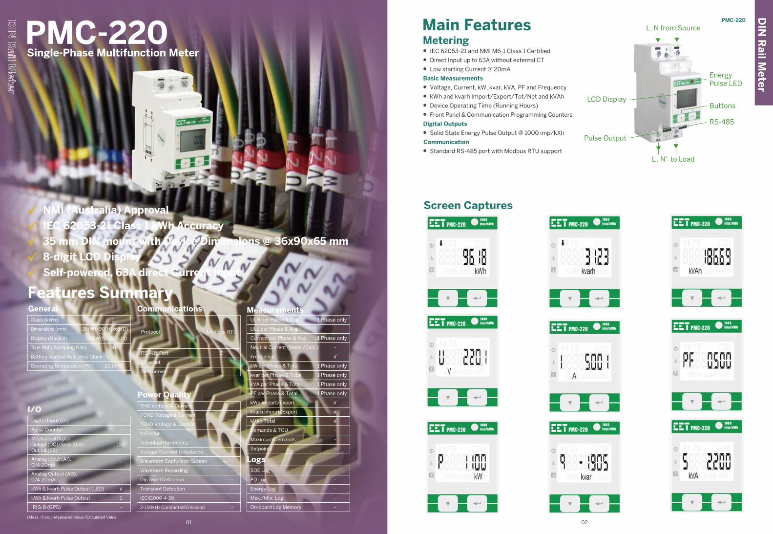
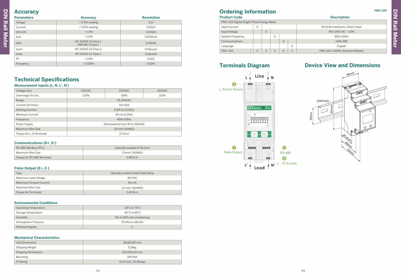
Main FeaturesMetering• IEC 62053-21 and NMI M6-1 Class 1 Certified
• Direct Input up to 63A without external CT
• Low starting Current @ 20mA
Basic Measurements
• Voltage, Current, kW, kvar, kVA, PF and Frequency
• kWh and kvarh Import/Export/Tot/Net and kVAh
• Device Operating Time (Running Hours)
• Front Panel & Communication Programming Counters
Digital Outputs
• Solid State Energy Pulse Output @ 1000 imp/kXh
Communication
• Standard RS-485 port with Modbus RTU support
Screen Captures
PMC-220Single-Phase Multifunction Meter
Features SummaryGeneral
Class (kWh)
Operating Temperature (ºC)
Dimensions (mm)
1
-25 to 70
36(W)x90(H)x65(D)
Display (Backlit)
True RMS Sampling Rate
Battery-backed Real-time Clock
B&W(No Backlit)
-
36
I/O-
1SS
-
1
-
-
√
-
Digital Input (DI)
Pulse Counter
Mechanical DigitalOutput (DO)/Solid StateOutput (SS)
Analog Input (AI),0/4-20mA
Analog Output (AO),0/4-20mA
kWh & kvarh Pulse Output (LED)
kWh & kvarh Pulse Output
IRIG-B (GPS)
Communications
Protocol
Ethernet
Modbus RTU
RS-485 Port 1
-
Web Server -
Power QualityTHD Voltage & Current
TOHD Voltage & Current
TEHD Voltage & Current
K-Factor
Individual Harmonics
Voltage/Current Unbalance
Waveform Capture on Screen
Waveform Recording
Dip Swell Detection
Transient Detection
-
-
-
-
-
-
-
-
-
-
IEC 61000-4-30
2-150kHz Conducted Emission
-
-
MeasurementsULN per Phase & Avg.
ULL per Phase & Avg.
Current per Phase & Avg.
Neutral Current (Meas./Calc.)
Frequency
kW per Phase & Total
kvar per Phase & Total
kVA per Phase & Total
PF per Phase & Total
kWh Import/Export
kvarh Import/Export
kVAh Total
Demands & TOU
Maximum Demands
Setpoints
1 Phase only
1 Phase only
√
1 Phase only
1 Phase only
√
-
-
-
-
1 Phase only
1 Phase only
√
√
-
LogsSOE Log
PQ Log
Energy Log
Max./Min. Log
On-board Log Memory
-
-
-
-
-
√ NMI (Australia) Approval
√ IEC 62053-21 Class 1 kWh Accuracy
√ 35 mm DIN mount with Device Dimensions @ 36x90x65 mm
√ 8-digit LCD Display
√ Self-powered, 63A direct Current Input
LCD Display
Pulse Output
EnergyPulse LED
Buttons
RS-485
L, N from Source
L', N' to Load
DIN
Rail M
eterPMC-220
0201(Meas./Calc.)-Measured Value/Calculated Value
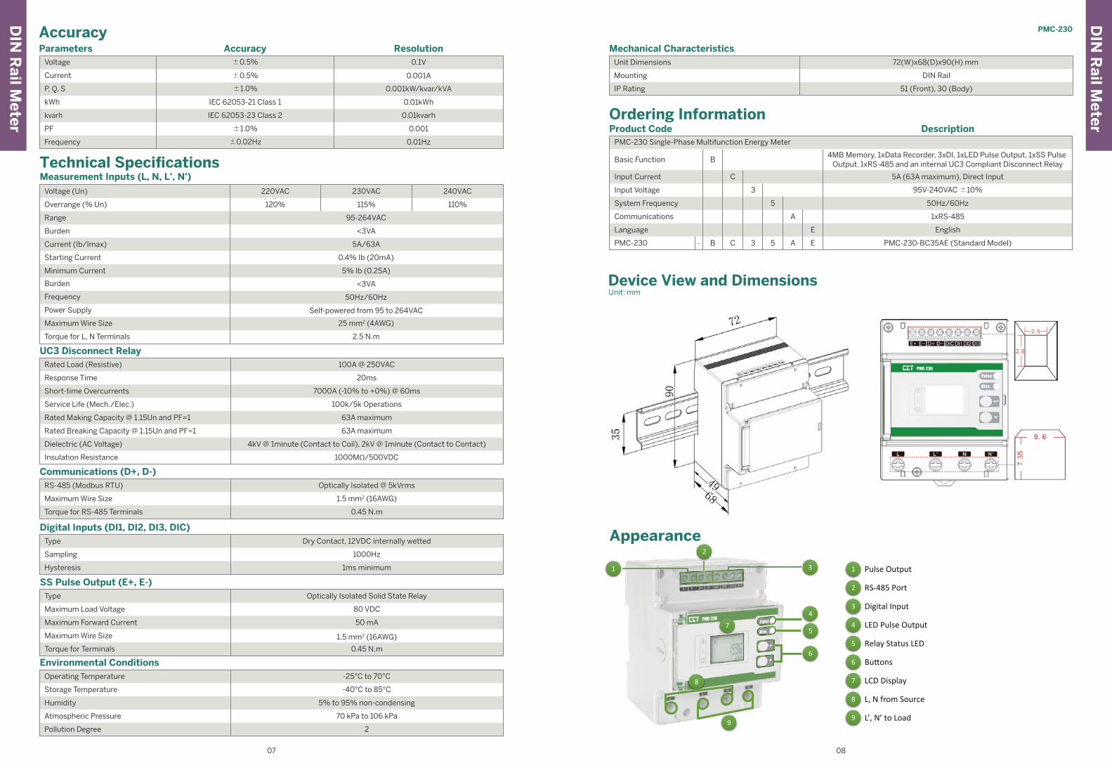
Terminals Diagram
ParametersVoltage ±0.5% reading
±0.5% reading
±1.0%
±1.0%
IEC 62053-23 Class 2
IEC 62053-21 Class 1 NMI M6-1 Class 1
IEC 62053-21 Class 1
±1.0%
±0.02Hz
Current
kW, kVA
kvar
kWh
kvarh
kVAh
PF
Frequency
0.1V
0.001A
0.001kX
0.001kvar
0.01kWh
0.01kvarh
0.01kVAh
0.001
0.01Hz
ResolutionAccuracy
Accuracy
RS-485 (Modbus RTU)
Maximum Wire Size
Torque for RS-485 Terminals
Communications (D+, D-)Optically Isolated @ 5kVrms
1.5mm2 (16AWG)
0.45 N.m
Type
Maximum Load Voltage
Maximum Forward Current
Maximum Wire Size
Torque for Terminals
Pulse Output (E+, E-) Optically Isolated Solid State Relay
80 VDC
50 mA
1.5 mm2 (16AWG)
0.45 N.m
Operating Temperature
Storage Temperature
Humidity
Atmospheric Pressure
Pollution Degree
Environmental Conditions-25°C to 70°C
-40°C to 85°C
5% to 95% non-condensing
70 kPa to 106 kPa
2
Unit Dimensions
Shipping Weight
Shipping Dimensions
Mounting
IP Rating
Mechanical Characteristics 36x65x90 mm
0.18kg
120x103x42 mm
DIN Rail
51 (Front), 30 (Body)
Technical Specifications
Overrange (% Un)
Range
Current (Ib/Imax)
Starting Current
Minimum Current
Frequency
Power Supply
Maximum Wire Size
Torque for L, N Terminals
45Hz-65Hz
Self-powered from 95 to 264VAC
25 mm2 (4AWG)
5A/63A
0.4% Ib (0.02A)
5% Ib (0.25A)
Measurement Inputs (L, N, L’, N’)
Voltage (Un)
2.5 N.m
95-264VAC
220VAC 230VAC 240VAC
120% 115% 110%
Product Code PMC-220 Digital Single-Phase Energy Meter
Input Current
System Frequency
Communications
Language
PMC-220
English
PMC-220-C35AE (Standard Model)
3
3
5
5
C
C-
A
A
E
E
95V-240V AC ±10%
45Hz-65Hz
1xRS-485
5A (63A maximum), Direct Input
Input Voltage
DescriptionOrdering Information
Device View and Dimensions
(DIN Rail)
35
mm
36mm
90
mm
35.4mm
49mm
65mmPulse Output RS-485
L, N from Source
L',N’ to Load
DIN
Rail M
eter
DIN
Rail M
eterPMC-220
03 04

PMC-230Single-Phase Multifunction Meter(With UC3 Disconnect Relay)
Features Summary General
Class (kWh)
Operating Temperature (ºC)
Dimensions (mm)
Display (Backlit)
True RMS Sampling Rate
Battery-backed Real-time Clock
1
-25 to 70
B&W(No Backlit)
√
72(W)x90(H)X68(D)
36
I/O3
1SS
-
1
-
√
√
-
Digital Input (DI)
Pulse Counter
Mechanical DigitalOutput (DO)/Solid StateOutput (SS)
Analog Input (AI),0/4-20mA
Analog Output (AO),0/4-20mA
kWh & kvarh Pulse Output (LED)
kWh & kvarh Pulse Output
IRIG-B (GPS)
Communications
Protocol
Ethernet
Modbus RTU
RS-485 Port 1
-
Web Server -
Power QualityTHD Voltage & Current
TOHD Voltage & Current
TEHD Voltage & Current
K-Factor
Individual Harmonics
Voltage/Current Unbalance
Waveform Capture on Screen
Waveform Recording
Dip Swell Detection
Transient Detection
√
-
-
-
-
-
-
-
-
-
IEC 61000-4-30
2-150kHz Conducted Emission
-
-
MeasurementsULN per Phase & Avg.
ULL per Phase & Avg.
Current per Phase & Avg.
Neutral Current (Meas./Calc.)
Frequency
kW per Phase & Total
kvar per Phase & Total
kVA per Phase & Total
PF per Phase & Total
kWh Import/Export
kvarh Import/Export
kVAh Total
Demands & TOU
Maximum Demands
Setpoints
1 Phase only
1 Phase only
√
1 Phase only
1 Phase only
√
√
-
-
-
1 Phase only
1 Phase only
√
√
√
LogsSOE Log
PQ Log
Energy Log
Max./Min. Log
On-board Log Memory
32 entries
√
4MB
-
-
√ 4MB for Event & Data Recording
√ NMI (Australia) Approval
√ IEC 62053-21 Class 1 kWh Accuracy
√ Self-powered, 63A direct Current Input
√ UC3 Disconnect Relay (Australia NER Compliance)
√ 35 mm DIN mount with Device Dimensions @ 72x90x68 mm
√ 8-digit LCD Display
Main FeaturesMetering• IEC 62053-21 Class 1 and NMI M6-1 Certified by UL
• Direct Input up to 63A with UC3 Disconnect Relay
• Low starting Current @ 20mA
Basic Measurements
• U, I, P, Q, S, PF, Frequency and Operating Time
• kWh and kvarh Import/Export and kVAh
• Two TOU schedules with 4 Seasons, 12 Daily Profiles
and 4 Tariffs
• Demands and Maximum Demands for U, I, P/Q/S
with Timestamp for This Month & Last Month (or
Since Last Reset & Before Last Reset)
• U and I THD
UC3 Disconnect Relay (Internal)
• UC3 Compliant Disconnect Relay that can be
activated locally from the Front Panel or remotely via
communication
Data and Event RecordersData Recorder
• 4MB Log Memory, capable of recording 16 parame-
ters at 5-minute interval for 6 months
• One Data Recorder Log of 16 parameters
• Recording Interval from 1 second to 40 days
• Configurable Depth (maximum 65535) and Recording
Offset
• Available parameters: U, I, P, Q, S, PF, Freq., kWh
Import/Export, kvarh Import/Export, Demands and
Maximum Demands for U, I, P/Q/S Total, DI Pulse
Counters and Relay Status
Monthly Energy Log
• 12 historical monthly logs of kWh/kvarh Import/Ex-
port and kVAh as well as kWh/kvarh Import/Export
and kVAh per Tariff
SOE Log
• 32 events time-stamped to ±1ms resolution
Inputs and OutputsDigital Inputs
• 3 channels for external status monitoring and pulse
counting
• Self-excited, internally wetted at 12VDC
• 1,000Hz sampling
Energy Pulse Outputs
• 1xLED Energy Pulse Output on the Front Panel
• 1xSolid State Relay Energy Pulse Output
Communications• Optically isolated RS-485 port at 1,200 to 19,200 bps
• Modbus RTU protocol with configurable password
protection
DIN
Rail M
eterPMC-230
05 06
Typical Application
L’ N’
LN
Metering
4MB Memory for Logs
Load
Other Feature
I/ O Features
Or
-Disconnect/Reconnect from the supply locally viathe Front Panel or remotely via Communica�on
UC3 Compliant Disconnect Relay
3xDigital Inputs
12 Monthly Energy Logs
Data Recorder with 16 Parameters
32 SOE Events �mestamped @ ±1ms
AEMO Type 4 Compliant
NMI Cer�fied
IEC 62053-21 Class 1 Compliant
1xSS Relay Pulse Output
1xLED Energy Pulse Output
RS-485Modbus RTU
3rd-Party Automa�on System Pecstar iEMS PMC-Setup
Source
(Meas./Calc.)-Measured Value/Calculated Value
Technical Specifications
Overrange (% Un)
Range
Burden
Current (Ib/Imax)
Starting Current
Minimum Current
Frequency
Burden
Power Supply
Maximum Wire Size
Torque for L, N Terminals
5% Ib (0.25A)
<3VA
50Hz/60Hz
<3VA
5A/63A
0.4% Ib (20mA)
Measurement Inputs (L, N, L’, N’)
Voltage (Un)
ParametersVoltage ±0.5%
±0.5%
±1.0%
IEC 62053-21 Class 1
±1.0%
IEC 62053-23 Class 2
±0.02Hz
Current
P, Q, S
kWh
kvarh
PF
Frequency
0.1V
0.001A
0.001kW/kvar/kVA
0.01kWh
0.01kvarh
0.001
0.01Hz
ResolutionAccuracy
Accuracy
RS-485 (Modbus RTU)
Maximum Wire Size
Torque for RS-485 Terminals
Communications (D+, D-)Optically Isolated @ 5kVrms
1.5 mm2 (16AWG)
0.45 N.m
Type
Sampling
Hysteresis
Digital Inputs (DI1, DI2, DI3, DIC)Dry Contact, 12VDC internally wetted
1000Hz
1ms minimum
Rated Load (Resistive)
Response Time
Short-time Overcurrents
Service Life (Mech./Elec.)
Rated Making Capacity @ 1.15Un and PF=1
Rated Breaking Capacity @ 1.15Un and PF=1
Dielectric (AC Voltage)
Insulation Resistance
UC3 Disconnect Relay 100A @ 250VAC
20ms
7000A (-10% to +0%) @ 60ms
100k/5k Operations
63A maximum
63A maximum
4kV @ 1minute (Contact to Coil), 2kV @ 1minute (Contact to Contact)
1000MΩ/500VDC
Type
Maximum Load Voltage
Maximum Forward Current
Maximum Wire Size
Torque for Terminals
SS Pulse Output (E+, E-) Optically Isolated Solid State Relay
80 VDC
50 mA
1.5 mm2 (16AWG)
0.45 N.m
Operating Temperature
Storage Temperature
Humidity
Atmospheric Pressure
Pollution Degree
Environmental Conditions -25°C to 70°C
-40°C to 85°C
5% to 95% non-condensing
70 kPa to 106 kPa
2
Self-powered from 95 to 264VAC
25 mm2 (4AWG)
2.5 N.m
95-264VAC
220VAC 230VAC 240VAC
120% 115% 110%
Unit Dimensions
Mounting
IP Rating
Mechanical Characteristics 72(W)x68(D)x90(H) mm
DIN Rail
51 (Front), 30 (Body)
Product Code PMC-230 Single-Phase Multifunction Energy Meter
Input Current
Basic Function
System Frequency
Communications
Language
PMC-230
English
PMC-230-BC35AE (Standard Model)
4MB Memory, 1xData Recorder, 3xDI, 1xLED Pulse Output, 1xSS Pulse Output, 1xRS-485 and an internal UC3 Compliant Disconnect Relay
3
3
5
5
C
B
B C-
A
A
E
E
95V-240VAC ±10%
50Hz/60Hz
1xRS-485
5A (63A maximum), Direct Input
Input Voltage
DescriptionOrdering Information
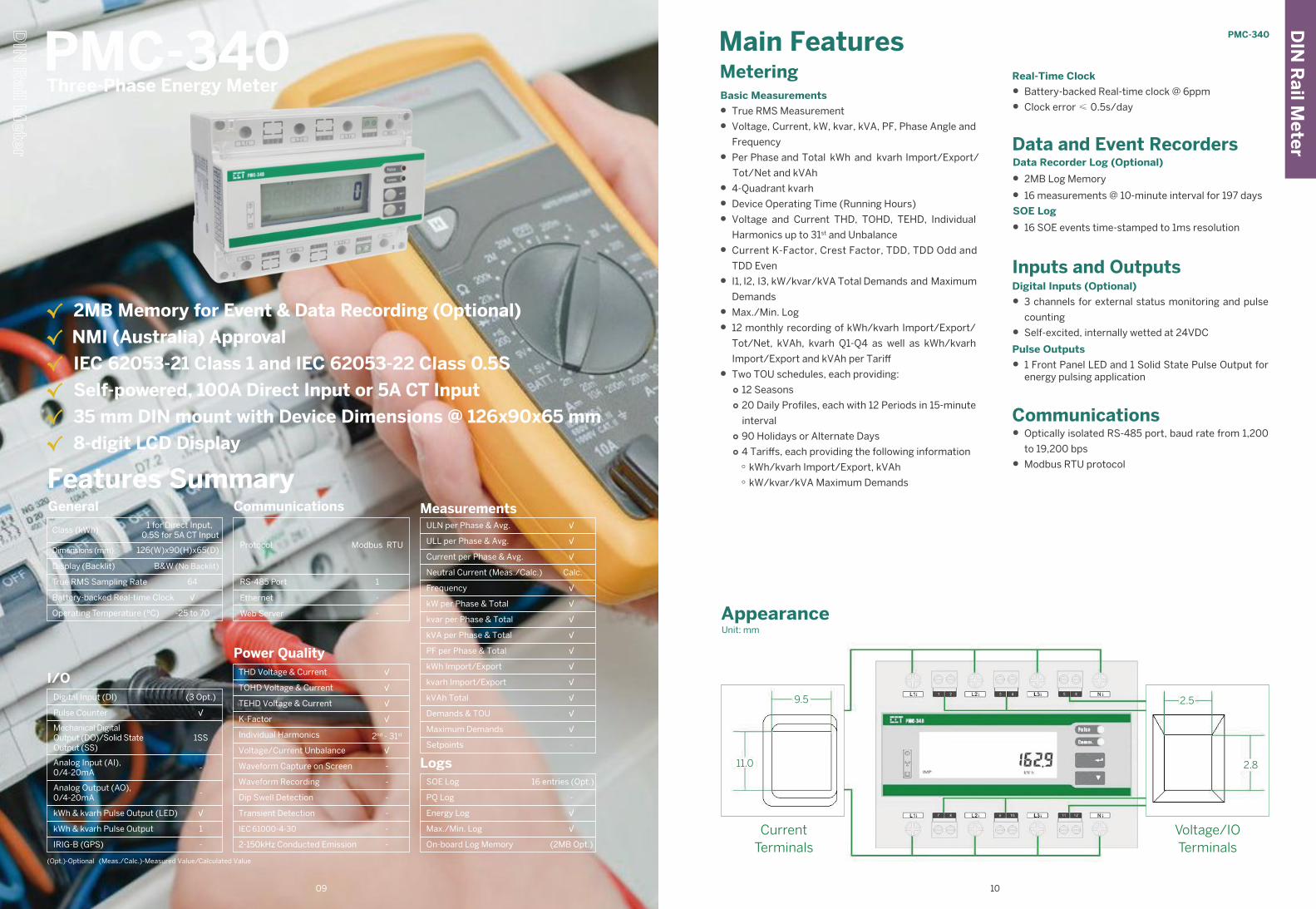
Device View and DimensionsUnit: mm
Appearance
3 1 Pulse Output
2 RS-485 Port
3 Digital Input
LED Pulse Output
5 Relay Status LED
6 Bu�ons
7 LCD Display
8
9 L’, N’ to Load
L, N from Source
1
2
4
5
6
7
8
9
DIN
Rail M
eter
DIN
Rail M
eter
PMC-230
07 08
4
Main FeaturesMetering
Features SummaryGeneral
Class (kWh)
Operating Temperature (ºC)
Dimensions (mm)
Display (Backlit)
True RMS Sampling Rate
Battery-backed Real-time Clock
1 for Direct Input, 0.5S for 5A CT Input
-25 to 70
B&W (No Backlit)
√
126(W)x90(H)x65(D)
64
I/O(3 Opt.)
1SS
-
1
-
√
√
-
Digital Input (DI)
Pulse Counter
Mechanical DigitalOutput (DO)/Solid StateOutput (SS)
Analog Input (AI),0/4-20mA
Analog Output (AO),0/4-20mA
kWh & kvarh Pulse Output (LED)
kWh & kvarh Pulse Output
IRIG-B (GPS)
Communications
Protocol
Ethernet
Modbus RTU
RS-485 Port 1
-
Web Server -
Power QualityTHD Voltage & Current
TOHD Voltage & Current
TEHD Voltage & Current
K-Factor
Individual Harmonics
Voltage/Current Unbalance
Waveform Capture on Screen
Waveform Recording
Dip Swell Detection
Transient Detection
√
√
2nd - 31st
-
-
√
√
√
-
-
IEC 61000-4-30
2-150kHz Conducted Emission
-
-
MeasurementsULN per Phase & Avg.
ULL per Phase & Avg.
Current per Phase & Avg.
Neutral Current (Meas./Calc.)
Frequency
kW per Phase & Total
kvar per Phase & Total
kVA per Phase & Total
PF per Phase & Total
kWh Import/Export
kvarh Import/Export
kVAh Total
Demands & TOU
Maximum Demands
Setpoints
√
√
√
√
√
√
√
-
√
Calc.
√
√
√
√
√
PMC-340Three-Phase Energy Meter
√ 2MB Memory for Event & Data Recording (Optional)
√ NMI (Australia) Approval
√ IEC 62053-21 Class 1 and IEC 62053-22 Class 0.5S
√ Self-powered, 100A Direct Input or 5A CT Input
√ 35 mm DIN mount with Device Dimensions @ 126x90x65 mm
√ 8-digit LCD Display
LogsSOE Log
PQ Log
Energy Log
Max./Min. Log
On-board Log Memory
16 entries (Opt.)
√
(2MB Opt.)
-
√
(Opt.)-Optional (Meas./Calc.)-Measured Value/Calculated Value
Basic Measurements
• True RMS Measurement
• Voltage, Current, kW, kvar, kVA, PF, Phase Angle and
Frequency
• Per Phase and Total kWh and kvarh Import/Export/
Net and kVAhTot/
• 4-Quadrant kvarh
• Device Operating Time (Running Hours)
• Voltage and Current THD, TOHD, TEHD, Individual
Harmonics up to 31st and Unbalance
• Current K-Factor, Crest Factor, TDD, TDD Odd and
TDD Even
• I1, I2, I3, kW/kvar/kVA Total Demands and Maximum
Demands
• Max./Min. Log
• 12 monthly recording of kWh/kvarh Import/Export/
Tot/Net, kVAh, kvarh Q1-Q4 as well as kWh/kvarh
Import/Export and kVAh per Tariff
• Two TOU schedules, each providing: ○ 12 Seasons ○ 20 Daily Profiles, each with 12 Periods in 15-minute
interval ○ 90 Holidays or Alternate Days ○ 4 Tariffs, each providing the following information ○ kWh/kvarh Import/Export, kVAh ○ kW/kvar/kVA Maximum Demands
Real-Time Clock
• Battery-backed Real-time clock @ 6ppm
• Clock error ≤ 0.5s/day
Data and Event RecordersData Recorder Log (Optional)
• 2MB Log Memory
• 16 measurements @ 10-minute interval for 197 days
SOE Log
• 16 SOE events time-stamped to 1ms resolution
Inputs and OutputsDigital Inputs (Optional)
• 3 channels for external status monitoring and pulse
counting
• Self-excited, internally wetted at 24VDC
Pulse Outputs
• 1 Front Panel LED and 1 Solid State Pulse Output for energy pulsing application
Communications • Optically isolated RS-485 port, baud rate from 1,200
to 19,200 bps
• Modbus RTU protocol
DIN
Rail M
eterPMC-340
09 10
CurrentTerminals
Voltage/IOTerminals
AppearanceUnit: mm
9.5 2.5
2.811.0
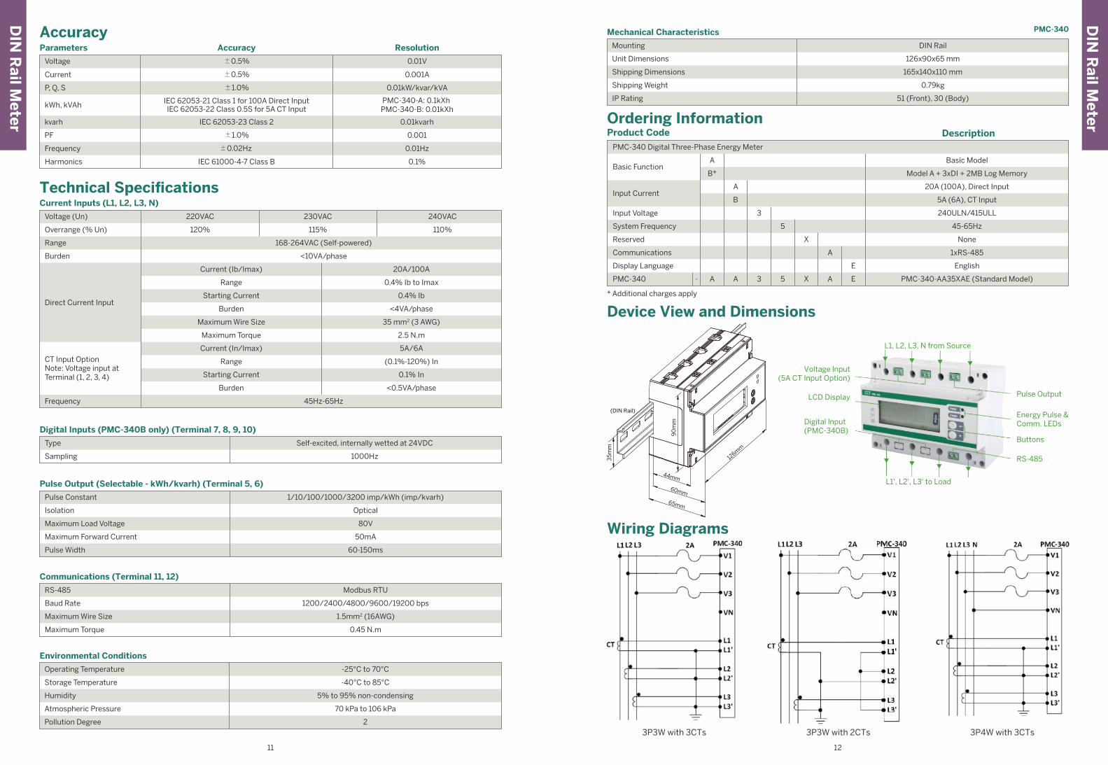
Voltage lnput(5A CT Input Option)
L1, L2, L3, N from Source
L1', L2', L3' to Load
Pulse Output
Energy Pulse &Comm. LEDs
Buttons
RS-485
LCD Display
Digital lnput(PMC-340B)
Type
Sampling
Digital Inputs (PMC-340B only) (Terminal 7, 8, 9, 10)
Self-excited, internally wetted at 24VDC
1000Hz
Operating Temperature
Storage Temperature
Humidity
Atmospheric Pressure
Pollution Degree
Environmental Conditions
-25°C to 70°C
-40°C to 85°C
5% to 95% non-condensing
70 kPa to 106 kPa
2
RS-485
Baud Rate
Maximum Wire Size
Maximum Torque
Communications (Terminal 11, 12)
Modbus RTU
1200/2400/4800/9600/19200 bps
1.5mm2 (16AWG)
0.45 N.m
Mounting
Unit Dimensions
Shipping Dimensions
Shipping Weight
IP Rating
Mechanical Characteristics
DIN Rail
126x90x65 mm
165x140x110 mm
0.79kg
51 (Front), 30 (Body)
Pulse Constant
Isolation
Maximum Load Voltage
Maximum Forward Current
Pulse Width
Pulse Output (Selectable - kWh/kvarh) (Terminal 5, 6)
Optical
80V
50mA
60-150ms
1/10/100/1000/3200 imp/kWh (imp/kvarh)
Ordering InformationProduct Code
PMC-340 Digital Three-Phase Energy Meter
Basic Function
System Frequency
Reserved
Communications
Display Language
PMC-340
English
PMC-340-AA35XAE (Standard Model)
B*
A
A-
B
A
3
X
E
A E3
5
A
5
X
45-65Hz
None
1xRS-485
Model A + 3xDI + 2MB Log Memory
5A (6A), CT Input
240ULN/415ULL
Basic Model
Input Current
Input Voltage
Description
* Additional charges apply
A 20A (100A), Direct Input
3P4W with 3CTs3P3W with 3CTs
Device View and Dimensions
90
mm
44mm
60mm
65mm
126m
m
35
mm
(DIN Rail)
3P3W with 2CTs
Wiring Diagrams
Technical Specifications
220VAC 230VAC 240VAC
Overrange (% Un)
Current (Ib/Imax)
Direct Current InputStarting Current
Burden
Maximum Wire Size
Maximum Torque
0.4% Ib
<4VA/phase
35 mm2 (3 AWG)
2.5 N.m
120% 115% 110%
20A/100A
Current Inputs (L1, L2, L3, N)
Voltage (Un)
Frequency 45Hz-65Hz
Current (In/Imax)
Range
Starting Current
Burden
5A/6A
(0.1%-120%) In
0.1% In
<0.5VA/phase
CT Input OptionNote: Voltage input at Terminal (1, 2, 3, 4)
168-264VAC (Self-powered)
<10VA/phase
0.4% Ib to ImaxRange
Burden
Range
Parameters
Voltage ±0.5%
±0.5%
±1.0%
±1.0%
IEC 62053-21 Class 1 for 100A Direct InputIEC 62053-22 Class 0.5S for 5A CT Input
IEC 62053-23 Class 2
±0.02Hz
IEC 61000-4-7 Class B
Current
P, Q, S
kWh, kVAh
kvarh
Frequency
Harmonics
0.01V
0.001A
0.01kW/kvar/kVA
PMC-340-A: 0.1kXh PMC-340-B: 0.01kXh
0.01kvarh
0.001
0.01Hz
0.1%
ResolutionAccuracy
Accuracy
PF
DIN
Rail M
eter
DIN
Rail M
eter
PMC-340
11 12

DIN
Rail M
eter
14
Main FeaturesMeteringBasic Measurements
• ULN, ULL per Phase and Average
• Current per Phase and Average with calculated Neutral
• kW, kvar, kVA per Phase and Total
• PF per Phase and Total
• kWh, kvarh Import/Export/Net/Total and kVAh Total
• Frequency
• Device Operating Time (Running Hours)
• Optional Iresidual and Temperature Measurements
• Optional DI for Status Monitoring and Utility Pulse Counting
Advanced Measurements
• U and I THD, TOHD, TEHD and Individual HD up to 31st
• Current TDD, TDD Odd, TDD Even, K-Factor and Crest Factor
• U and I Unbalance and Phase Angle
• Fundamental kW and PF
• kvarh Q1-Q4
• Present, Predicted and Max. Demands
Multi-Tariff TOU Capability
• Two TOU schedules, each providing ○ 12 Seasons○ 20 Daily Profiles with 12 Periods in 15-minute interval○ 90 Holidays or Alternate Days○ 8 Tariffs, each providing the following information
○ kWh/kvarh Import/Export, kVAh○ kW/kvar/kVA Max. Demands
Data and Event RecordersMax./Min. Log
• Max./Min. Log with Timestamp for Real-time measurements
• Configurable for This Month/Last Month or
Before/Since Last Reset
Monthly Energy Log
Daily/Monthly Freeze Log
• Daily/Monthly Log with Timestamp for kWh, kvarh,
kVAh Total and Max. Demands for kW, kvar, kVA Total
• Available through Modbus and LoRaWAN communi-
cations for 60 Daily Freeze records (2 months) and
36 Monthly Freeze records (3 years)
Data Recorder
• 5 Data Recorders (16 parameters each)
• Recording interval from 1 minute to 40 days
SOE Log
• 100 events time-stamped to ±1ms resolution
Inputs and Outputs• 4xDI + 2xDO (Mechanical Relay)
• 4xDI + 2xSS Pulse Output
• 4xRTD + 1xIresidual Inputs (PT100 sensor & Residual
CT not included)
CommunicationsRS-485
• Optically isolated RS-485 port at 1200 to 38,400 bps
• Modbus RTU protocol
• Optional LoRaWAN support at AS923/KR920 for IoT
applications
Autonomous Data Push with the LoRaWAN option
• DevEUI (End-Device Identifier), AppEUI (Application
Identifier) and AppKey (AES-128 key) for OTAA activation
• User selectable Auto-Push Data Packages of
Real-time measurements, Energy, Demands,
Harmonics, Max./Min. Logs, Freeze Logs, I/O and
Setpoint status can be autonomously pushed to the
LoRaWAN Network Server in configurable interval* Not all measurements are available via the wireless LoRaWAN option.
Setpoints• 10 user programmable Setpoints with extensive list
of monitoring parameters including Voltage, Current,
Power and THD, etc.
• Configurable thresholds, time delays and DO triggers
PMC-350-C
Features SummaryGeneral
Class (kWh)
Operating Temperature (ºC)
Dimensions (mm)
Display (Backlit)
True RMS Sampling Rate
Battery-backed Real-time Clock
1
-25 to 70
B&W (No Backlit)
√
72(W)x95(H)X70(D)
64
I/O(4 Opt.)
(2 Opt.)DO or(2 Opt.)SS
-
2
-
√
√
-
Digital Input (DI)
Pulse Counter
Mechanical DigitalOutput (DO)/Solid StateOutput (SS)
Analog Input (AI),0/4-20mA
Analog Output (AO),0/4-20mA
kWh & kvarh Pulse Output (LED)
kWh & kvarh Pulse Output
IRIG-B (GPS)
Communications
Protocol
Ethernet
Modbus RTU (Optional LoRaWAN
support at AS923/KR920)
RS-485 Port 1
-
Web Server -
Power QualityTHD Voltage & Current
TOHD Voltage & Current
TEHD Voltage & Current
K-Factor
Individual Harmonics
Voltage/Current Unbalance
Waveform Capture on Screen
Waveform Recording
Dip Swell Detection
Transient Detection
√
√
2nd - 31st
-
-
√
√
√
-
-
IEC 61000-4-30
2-150kHz Conducted Emission
-
-
MeasurementsULN per Phase & Avg.
ULL per Phase & Avg.
Current Per Phase & Avg.
Neutral Current (Meas./Calc.)
Frequency
kW per Phase & Total
kvar per Phase & Total
kVA per Phase & Total
PF per Phase & Total
kWh Import/Export
kvarh Import/Export
kVAh Total
Demands & TOU
Maximum Demands
Setpoints
√
√
√
√
√
√
√
√
√
√
√
√
√
√
√
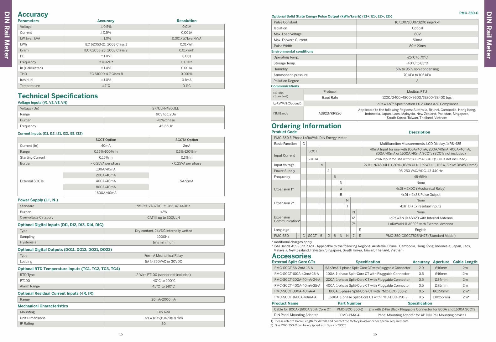
PMC-350-CThree-Phase Energy Meter
√ 4MB for Event & Data Recording
√ Optional AS923/KR920 LoRaWAN Module
√ IEC 62053-21 Class 1 and IEC 62053-23 Class 2
√ Optional Split-Core CT (SCCT)
√ 35 mm DIN mount with Device Dimensions @ 72x95x70 mm
LogsSOE Log
PQ Log
Energy Log
Max./Min. Log
On-board Log Memory
100 entries
√
4MB
-
√
(Opt.)-Optional (Meas./Calc.)-Measured Value/Calculated Value
13
Typical ApplicationPMC-350-C Measurements:Temperature & DI Status,U, I, P, Q, S, Freq.,PF, Unbalance, Harmonics.
• 12 monthly recording of kWh, kvarh Import/Export/
Total/Net, kVAh, kvarh Q1-Q4 as well as kWh/kvarh
Import/Export and kVAh per Tariff
DIN
Rail M
eter
DIN
Rail M
eter
PMC-350-C
1615
Standard
Burden
Overvoltage Category
Power Supply (L+, N-)
95-250VAC/DC, ±10%, 47-440Hz
CAT III up to 300ULN
<2W
Type
Sampling
Hysteresis
Optional Digital Inputs (DI1, DI2, DI3, DI4, DIC)
Dry contact, 24VDC internally wetted
1ms minimum
1000Hz
RTD Type
PT100
Alarm Range
Optional RTD Temperature Inputs (TC1, TC2, TC3, TC4)
2-Wire PT100 (sensor not included)
45°C to 140°C
-40°C to 200°C
Mounting
Unit Dimensions
IP Rating
Mechanical Characteristics
DIN Rail
30
72(W)x95(H)X70(D) mm
Product Name Part Number
Cable for 800A/1600A Split-Core CT
DIN Panel Mounting Adapter
Specification
Panel Mounting Adapter for 4P DIN Rail Mounting devices
2m with 2-Pin Black Pluggable Connector for 800A and 1600A SCCTs
PMC-PMA-4
PMC-BCC-350-2
Type
Loading
Optional Digital Outputs (DO11, DO12, DO21, DO22)
Form A Mechanical Relay
5A @ 250VAC or 30VDC
Range
Optional Residual Current Inputs (·IR, IR)
20mA-2000mA
Parameters ResolutionAccuracyAccuracy
Voltage
kW, kvar, kVA
kWh
Current
kvarh
Frequency
0.01V
0.001kW/kvar/kVA
0.01kWh
0.001A
0.01kvarh
0.01Hz
THD 0.001%
PF 0.001
±0.5%
±1.0%
IEC 62053-21: 2003 Class 1
±0.5%
IEC 62053-23: 2003 Class 2
±0.02Hz
0.1°C
Iresidual ±1.0%
IEC 61000-4-7 Class B
±1.0%
Temperature
0.1mA
±1°C
±1.0% 0.001AIn (Calculated)
Technical SpecificationsVoltage Inputs (V1, V2, V3, VN)
Voltage (Un) 277ULN/480ULL
Burden
Frequency
<2W/phase
Range 90V to 1.2Un
45-65Hz
Current Inputs (I11, I12, I21, I22, I31, I32)
Range
Starting Current
Current (In)
Burden
SCCTA Option
0.1%-120% In
0.1% In
2mA
<0.25VA per phase
SCCT Option
0.15%-100% In
0.15% In
40mA
<0.25VA per phase
200A/40mA
800A/40mA
100A/40mA
1600A/40mA
400A/40mAExternal SCCTs 5A/2mA
Pulse Constant
Isolation
Max. Load Voltage
Max. Forward Current
Pulse Width
Optional Solid State Energy Pulse Output (kWh/kvarh) (E1+, E1-, E2+, E2-)
10/100/1000/3200 imp/kxh
Optical
80V
50mA
80±20ms
Operating Temp.
Storage Temp.
Humidity
Atmospheric pressure
Pollution Degree
Environmental conditions
-25°C to 70°C
-40°C to 85°C
5% to 95% non-condensing
70 kPa to 106 kPa
2
Communications
LoRaWANTM Specification 1.0.2 Class A/C Compliance
Applicable to the following Regions: Australia, Brunei, Cambodia, Hong Kong,Indonesia, Japan, Laos, Malaysia, New Zealand, Pakistan, Singapore,
South Korea, Taiwan, Thailand, Vietnam
Modbus RTU
1200/2400/4800/9600/19200/38400 bps
Protocol
AS923/KR920
Baud Rate
RS-485(Standard)
LoRaWAN (Optional)
ISM Bands
Ordering InformationProduct Code
Basic Function
Power Supply
Frequency
Expansion 1*
Expansion 2*
Language
PMC-350
ExpansionCommunication*
Model A + 3xDI + 2MB Log Memory
Multifunction Measurements, LCD Display, 1xRS-485
Input Voltage
Description
C- 5 2 5 N N 7 ESCCT
2mA Input for use with 5A/2mA SCCT (SCCTs not included)
95-250 VAC/VDC, 47-440Hz
45-65Hz
None
4xDI + 2xDO (Mechanical Relay)
4xDI + 2xSS Pulse Output
None
277ULN/480ULL + 20% (1P2W ULN, 1P2W ULL, 1P3W, 3P3W, 3P4W, Demo)
C
5
5
N
A
B
N
T
N
7#
6#
E
2
SCCT
SCCTA
PMC-350 3-Phase LoRaWAN DIN Energy Meter
40mA Input for use with 100A/40mA, 200A/40mA, 400A/40mA, 800A/40mA or 1600A/40mA SCCTs (SCCTs not included)
Input Current
4xRTD + 1xIresidual Inputs
LoRaWAN @ AS923 with Internal Antenna
LoRaWAN @ AS923 with External Antenna
None
English
PMC-350-CSCCT525NN7E (Standard Model)
AccessoriesExternal Split-Core CTs
1) Please refer to Cable Length for details and contact the factory in advance for special requirements2) One PMC-350-C can be equipped with 3 pcs of SCCT
0.5 2mØ24mm
Specification Accuracy Aperture Cable Length
PMC-SCCT-100A-40mA-16-A 0.5 2mØ16mm100A, 1-phase Split-Core CT with Pluggable Connector
200A, 1-phase Split-Core CT with Pluggable Connector
0.5 2mØ35mm
PMC-SCCT-200A-40mA-24-A
PMC-SCCT-400A-40mA-35-A 400A, 1-phase Split-Core CT with Pluggable Connector
PMC-SCCT-800A-40mA-A 0.5 2m*80x50mm800A, 1-phase Split-Core CT with PMC-BCC-350-2
PMC-SCCT-1600A-40mA-A 0.5 2m*130x55mm1600A, 1-phase Split-Core CT with PMC-BCC-350-2
PMC-SCCT-5A-2mA-16-A 2.0 2mØ16mm5A/2mA, 1-phase Split-Core CT with Pluggable Connector
* Additional charges apply# ISM Bands AS923/KR920 - Applicable to the following Regions: Australia, Brunei, Cambodia, Hong Kong, Indonesia, Japan, Laos, Malaysia, New Zealand, Pakistan, Singapore, South Korea, Taiwan, Thailand, Vietnam
Features Summary General
Class (kWh)
Operating Temperature (ºC)
Dimensions (mm)
Display (Backlit)
True RMS Sampling Rate
Battery-backed Real-time Clock
1
-25 to 70
-
-
36(W)x90(H)x65(D)
64
I/O3
-
-
-
-
√
-
-
Digital Input (DI)
Pulse Counter
Mechanical DigitalOutput (DO)/Solid StateOutput (SS)
Analog Input (AI),0/4-20mA
Analog Output (AO),0/4-20mA
kWh & kvarh Pulse Output (LED)
kWh & kvarh Pulse Output
IRIG-B (GPS)
Communications
Protocol
Ethernet
Modbus RTU (Built-in LoRawith configurable ISM Bandsfor EU863-870, RU864-870,
IN865-867, US902-928, AU915-928,AS920-923 and AS923-925)
RS-485 Port 1
-
Web Server -
Power QualityTHD Voltage & Current
TOHD Voltage & Current
TEHD Voltage & Current
K-Factor
Individual Harmonics
Voltage/Current Unbalance
Waveform Capture on Screen
Waveform Recording
Dip Swell Detection
Transient Detection
√
√
2nd - 31st
-
-
√
-
√
-
-
IEC 61000-4-30
2-150kHz Conducted Emission
-
-
MeasurementsULN per Phase & Avg.
ULL per Phase & Avg.
Current Per Phase & Avg.
Neutral Current (Meas./Calc.)
Frequency
kW per Phase & Total
kvar per Phase & Total
kVA per Phase & Total
PF per Phase & Total
kWh Import/Export
kvarh Import/Export
kVAh Total
Demands & TOU
Maximum Demands
Setpoints
√
√
√
√
√
√
Dmd. Only
√
√
-
√
√
√
√
-
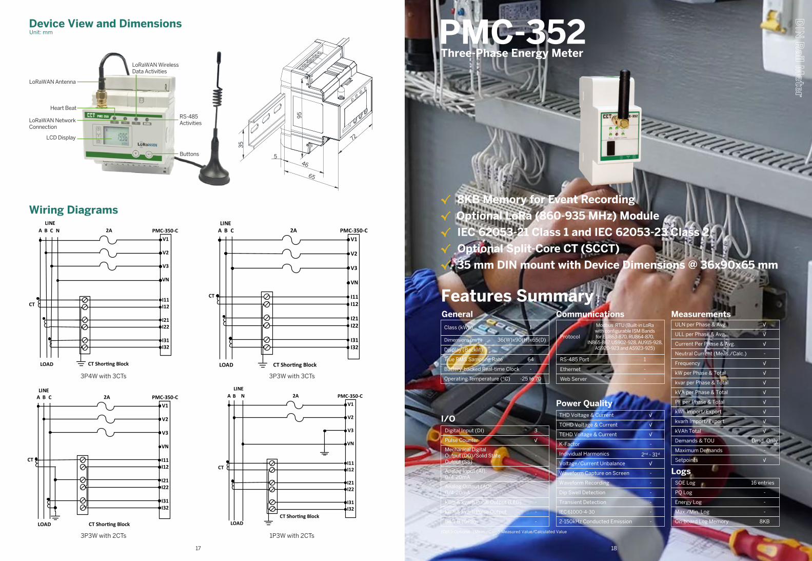
PMC-352Three-Phase Energy Meter
√ 8KB Memory for Event Recording
√ Optional LoRa (860-935 MHz) Module
√ IEC 62053-21 Class 1 and IEC 62053-23 Class 2
√ Optional Split-Core CT (SCCT)
√ 35 mm DIN mount with Device Dimensions @ 36x90x65 mm
LogsSOE Log
PQ Log
Energy Log
Max./Min. Log
On-board Log Memory
16 entries
-
8KB
-
-
(Opt.)-Optional (Meas./Calc.)-Measured Value/Calculated Value
1817
Device View and DimensionsUnit: mm
Wiring Diagrams
72
95
65
46
35
5
1P3W with 2CTs
3P3W with 3CTs3P4W with 3CTs
3P3W with 2CTs
PMC-350-C
LOAD CT Shor�ng Block
A B CLINE
2AV1
V2
V3
VN
I11I12
I21I22
I31I32
CT
CT
A B CLINE
PMC-350-CV1
V2
V3
VN
I11I12
I21I22
I31I32
2A
CT
LOAD CT Shor�ng Block
N
PMC-350-C
LOAD CT Shor�ng Block
A B CLINE
2AV1
V2
V3
VN
I11I12
I21I22
I31I32
A NLINE
PMC-350-CV1
V2
V3
VN
I11I12
I21I22
I31I32
2A
CT
LOADCT Shor�ng Block
B
LoRaWAN Antenna
LoRaWAN NetworkConnection
LoRaWAN Wireless Data Activities
RS-485Activities
LCD Display
Buttons
Heart Beat
DIN
Rail M
eter
DIN
Rail M
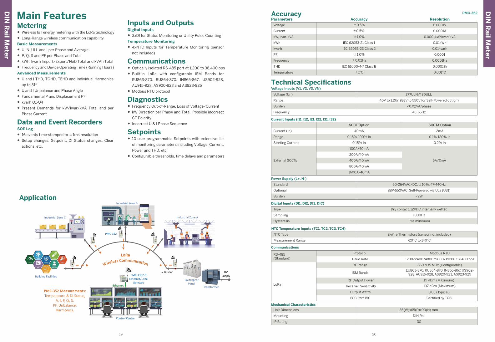
eterPMC-352Main Features
Metering• Wireless IoT energy metering with the LoRa technology
• Long-Range wireless communication capability
Basic Measurements
• ULN, ULL and I per Phase and Average
• P, Q, S and PF per Phase and Total
• kWh, kvarh Import/Export/Net/Total and kVAh Total
• Frequency and Device Operating Time (Running Hours)
Advanced Measurements
• U and I THD, TOHD, TEHD and Individual Harmonics
up to 31st
• U and I Unbalance and Phase Angle
• Fundamental P and Displacement PF
• kvarh Q1-Q4
• Present Demands for kW/kvar/kVA Total and per
Phase Current
Data and Event RecordersSOE Log
• 16 events time-stamped to ±1ms resolution
• Setup changes, Setpoint, DI Status changes, Clear
actions, etc.
Inputs and OutputsDigital Inputs
• 3xDI for Status Monitoring or Utility Pulse Counting
Temperature Monitoring
• 4xNTC Inputs for Temperature Monitoring (sensor
not included)
Communications• Optically isolated RS-485 port at 1,200 to 38,400 bps
• Built-in LoRa with configurable ISM Bands for
EU863-870, RU864-870, IN865-867, US902-928,
AU915-928, AS920-923 and AS923-925
• Modbus RTU protocol
Diagnostics• Frequency Out-of-Range, Loss of Voltage/Current
• kW Direction per Phase and Total, Possible incorrect
CT Polarity
• Incorrect U & I Phase Sequence
Setpoints• 10 user programmable Setpoints with extensive list
of monitoring parameters including Voltage, Current,
Power and THD, etc.
• Configurable thresholds, time delays and parameters
19 20
HV Supply
Switchgear Panel
TransformerEthernet
Control Centre
Industrial Zone A
Industrial Zone B
Industrial Zone C
Building Facili�es
PMC-352
LV BusbarPMC-1302-3
Ethernet/LoRaGateway
PMC-352 Measurements:Temperature & DI Status,
V, I, P, Q, S,PF, Unbalance,
Harmonics.
Application
Parameters ResolutionAccuracyAccuracy
Voltage
kW, kvar, kVA
kWh
Current
kvarh
Frequency
0.0001V
0.0001kW/kvar/kVA
0.01kWh
0.0001A
0.01kvarh
0.0001Hz
PF 0.0001
±0.5%
±1.0%
IEC 62053-21 Class 1
±0.5%
IEC 62053-23 Class 2
±0.02Hz
THD 0.0001%IEC 61000-4-7 Class B
±1.0%
Temperature 0.001°C±1°C
Technical SpecificationsVoltage Inputs (V1, V2, V3, VN)
Voltage (Un) 277ULN/480ULL
Burden
Frequency
<0.02VA/phase
Range 40V to 1.2Un (88V to 550V for Self-Powered option)
45-65Hz
Power Supply (L+, N-)
Standard 60-264VAC/DC, ±10%, 47-440Hz
Burden <2W
Optional 88V-550VAC, Self-Powered via Uca (U31)
Digital Inputs (DI1, DI2, DI3, DIC)
Type Dry contact, 12VDC internally wetted
Hysteresis 1ms minimum
Sampling 1000Hz
NTC Temperature Inputs (TC1, TC2, TC3, TC4)
NTC Type 2-Wire Thermistors (sensor not included)
Measurement Range -20°C to 140°C
Current Inputs (I11, I12, I21, I22, I31, I32)
Current (In)
Range
Starting Current
External SCCTs
SCCTA OptionSCCT Option
2mA
0.1%-120% In
0.2% In
5A/2mA
40mA
0.15%-100% In
0.15% In
100A/40mA
800A/40mA
1600A/40mA
400A/40mA
200A/40mA
RS-485(Standard)
LoRa
Modbus RTUProtocol
1200/2400/4800/9600/19200/38400 bps
860-935 MHz (Configurable)
EU863-870, RU864-870, IN865-867, US902-928, AU915-928, AS920-923, AS923-925
Baud Rate
RF Range
ISM Bands
Output Watts
FCC Part 15C
Receiver Sensitivity
RF Output Power
Communications
19 dBm (Maximum)
-137 dBm (Maximum)
0.03 (Typical)
Certified by TCB
Unit Dimensions 36(W)x65(D)x90(H) mm
IP Rating 30
Mounting DIN Rail
Mechanical Characteristics
DIN
Rail M
eter
DIN
Rail M
eterPMC-352
21 22
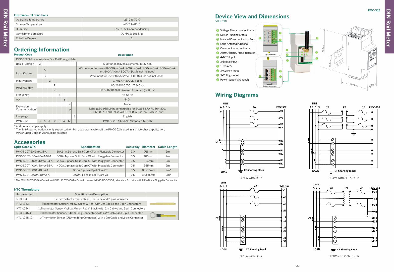
Wiring Diagrams
* Additional charges apply^ The Self-Powered option is only supported for 3-phase power system. If the PMC-352 is used in a single-phase application,
Power Supply option 2 should be selected
Ordering InformationProduct Code
Basic Function
Power Supply
Input Voltage
Description
C
3
Frequency
I/O
5
A
2
N*
A
BInput Current
PMC-352 3-Phase Wireless DIN Rail Energy Meter
60-264VAC/DC, 47-440Hz
277ULN/480ULL ±15%
88-550VAC, Self-Powered from Uca (or U31)^
45-65Hz
3×DI
Multifunction Measurements, 1xRS-485
2mA lnput for use with 5A/2mA SCCT (SCCTs not included)
40mA lnput for use with 100A/40mA, 200A/40mA, 400A/40mA, 800A/40mA or 1600A/40mA SCCTs (SCCTs not included)
N
7*
PMC-352 C 3 2 5 A N EA
E
None
PMC-352-CA325ANE (Standard Model)
English
LoRa (860-935 MHz) configurable for EU863-870, RU864-870, IN865-867, US902-928, AU915-928, AS920-923, AS923-925
Language
ExpansionCommunication*
CT
3P4W With 3PTs, 3CTs
A B CLINE
PMC-352
LOAD CT Shor�ng Block
N 2A 2APT
3P4W with 3CTs
A B CLINE
PMC-352V1
V2
V3VN
I11I12
I21I22
I31I32
2A
LOADCT Shor�ng Block
N
CT
3P3W with 3CTs
CT
PMC-352
LOAD CT Shor�ng Block
A B CLINE
2AV1
V2
V3
VN
I11I12
I21I22
I31I32
3P3W with 2PTs, 3CTs
CT
PMC-352
LOAD CT Shor�ng Block
A B CLINE
2A PT 2A
V1
V2
V3
VN
I11I12
I21I22
I31I32
90
.0m
m
65.0mm36.0mm
35
.0m
m
Device View and DimensionsUnit: mm
Voltage Phase Loss IndicatorA
Device Running StatusB
Infrared Communication PortC
LoRa Antenna (Optional)D
Communication IndicatorE
Alarm/Energy Pulse IndicatorF
4xNTC InputG
3xDigital InputH
1xRS-485I
3xCurrent InputJ
3xVoltage InputK
Power Supply (Optional)L
Operating Temperature -25°C to 70°C
Humidity
Pollution Degree
Atmospheric pressure
5% to 95% non-condensing
Storage Temperature -40°C to 85°C
70 kPa to 106 kPa
2
Environmental Conditions
AccessoriesSplit-Core CTs
* The PMC-SCCT-800A-40mA-A and PMC-SCCT-1600A-40mA-A come with PMC-BCC-350-2, which is a 2m cable with 2-Pin Black Pluggable Connector
0.5 2mØ24mm
Specification Accuracy Diameter Cable Length
PMC-SCCT-100A-40mA-16-A 0.5 2mØ16mm100A, 1-phase Split-Core CT with Pluggable Connector
200A, 1-phase Split-Core CT with Pluggable Connector
0.5 2mØ35mm
PMC-SCCT-200A-40mA-24-A
PMC-SCCT-400A-40mA-35-A 400A, 1-phase Split-Core CT with Pluggable Connector
PMC-SCCT-800A-40mA-A 0.5 2m*80x50mm800A, 1-phase Split-Core CT
PMC-SCCT-1600A-40mA-A 0.5 2m*130x55mm1600A, 1-phase Split-Core CT
PMC-SCCT-5A-2mA-16-A 2.0 2mØ16mm5A/2mA, 1-phase Split-Core CT with Pluggable Connector
NTC Thermistors
NTC-104 1xThermistor Sensor with a 0.3m Cable and 2-pin Connector
3xThermistor Sensor (Yellow, Green & Red) with 2m Cables and 2-pin ConnectorsNTC-1043
NTC-1044 4xThermistor Sensor (Yellow, Green, Red & Black) with 2m Cables and 2-pin Connectors
NTC-104M4 1xThermistor Sensor (Ø4mm Ring Connector) with a 2m Cable and 2-pin Connector
NTC-104M10 1xThermistor Sensor (Ø10mm Ring Connector) with a 2m Cable and 2-pin Connector
Part Number Specification/Description
DIN
Rail M
eter
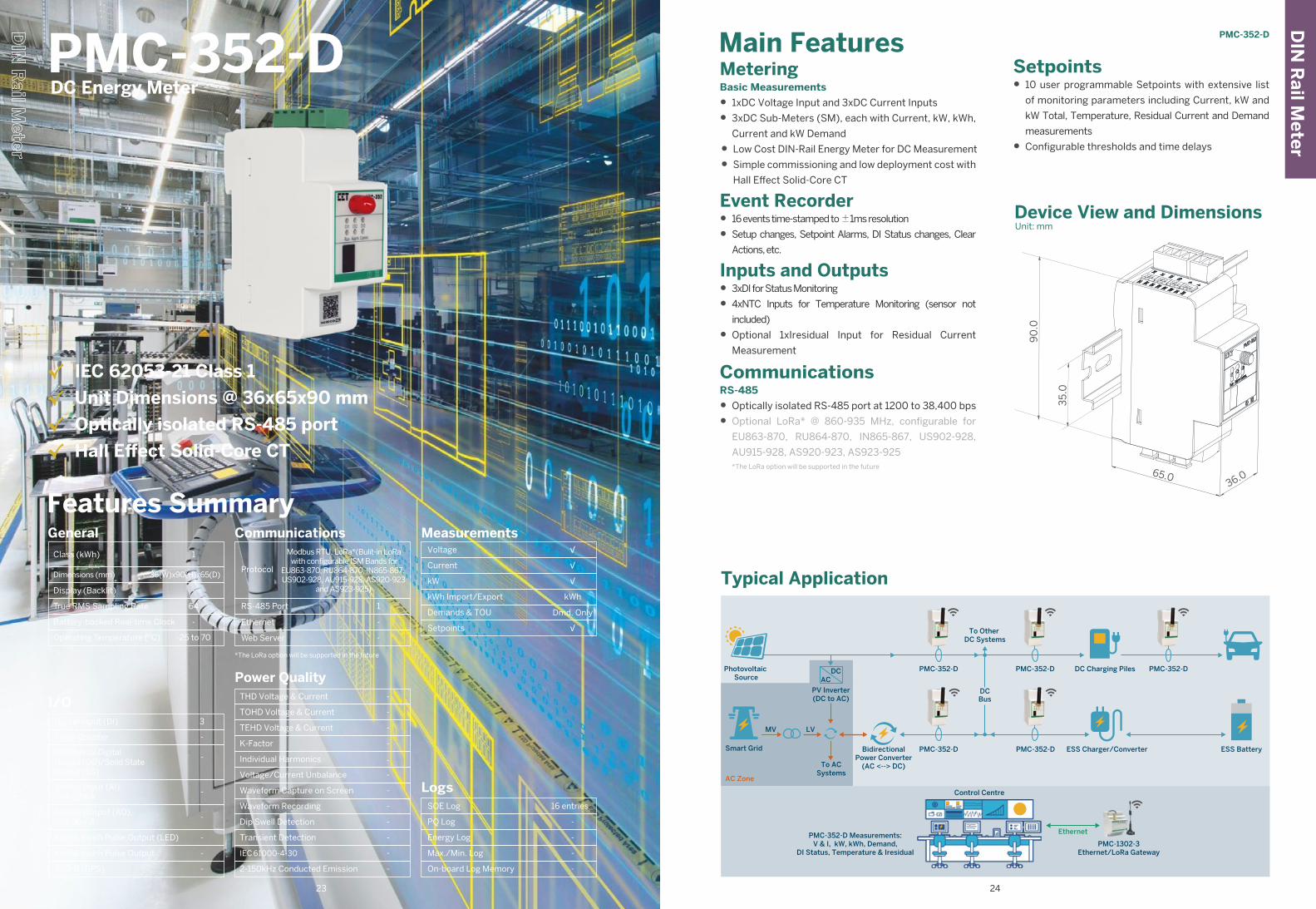
Main FeaturesMeteringBasic Measurements
• 1xDC Voltage Input and 3xDC Current Inputs
• 3xDC Sub-Meters (SM), each with Current, kW, kWh,
Current and kW Demand
• Low Cost DIN-Rail Energy Meter for DC Measurement
• Simple commissioning and low deployment cost with
Hall Effect Solid-Core CT
Event Recorder• 16 events time-stamped to ±1ms resolution
• Setup changes, Setpoint Alarms, DI Status changes, Clear
Actions, etc.
Inputs and Outputs• 3xDI for Status Monitoring
• 4xNTC Inputs for Temperature Monitoring (sensor not
included)
• Optional 1xIresidual Input for Residual Current
Measurement
CommunicationsRS-485
• Optically isolated RS-485 port at 1200 to 38,400 bps
• Optional LoRa* @ 860-935 MHz, configurable for
EU863-870, RU864-870, IN865-867, US902-928,
AU915-928, AS920-923, AS923-925 *The LoRa option will be supported in the future
Setpoints• 10 user programmable Setpoints with extensive list
of monitoring parameters including Current, kW and
kW Total, Temperature, Residual Current and Demand
measurements
• Configurable thresholds and time delays
PMC-352-D
PMC-352-DDC Energy Meter
√ IEC 62053-21 Class 1
√ Unit Dimensions @ 36x65x90 mm
√ Optically isolated RS-485 port
√ Hall Effect Solid-Core CT
Features SummaryGeneral
Class (kWh)
Operating Temperature (ºC)
Dimensions (mm)
Display (Backlit)
True RMS Sampling Rate
Battery-backed Real-time Clock
1
-25 to 70
-
-
36(W)x90(H)x65(D)
64
I/O3
-
-
-
-
-
-
-
Digital Input (DI)
Pulse Counter
Mechanical DigitalOutput (DO)/Solid StateOutput (SS)
Analog Input (AI),0/4-20mA
Analog Output (AO),0/4-20mA
kWh & kvarh Pulse Output (LED)
kWh & kvarh Pulse Output
IRIG-B (GPS)
Communications
Protocol
Ethernet
RS-485 Port
*The LoRa option will be supported in the future
1
-
Web Server -
Power QualityTHD Voltage & Current
TOHD Voltage & Current
TEHD Voltage & Current
K-Factor
Individual Harmonics
Voltage/Current Unbalance
Waveform Capture on Screen
Waveform Recording
Dip Swell Detection
Transient Detection
-
-
-
-
-
-
-
-
-
-
IEC 61000-4-30
2-150kHz Conducted Emission
-
-
MeasurementsVoltage
Current
kW
kWh Import/Export
Demands & TOU
Setpoints
√
√
Dmd. Only
√
kWh
√
LogsSOE Log
PQ Log
Energy Log
Max./Min. Log
On-board Log Memory
16 entries
-
-
-
-
LoRa*(Bulit-in LoRa with configurable ISM Bands for
EU863-870, RU864-870, IN865-867, US902-928, AU915-928, AS920-923
and AS923-925)Typical Application
Control Centre
Photovoltaic Source
To ACSystems
AC Zone
Smart Grid
PMC-1302-3Ethernet/LoRa Gateway
PMC-352-D Measurements:V & I, kW, kWh, Demand,
DI Status, Temperature & Iresidual
BidirectionalPower Converter
(AC <--> DC)
ESS Charger/Converter ESS Battery
DC Charging Piles
MV LV
PMC-352-D
DCBus
To Other DC Systems
PMC-352-D PMC-352-D
Ethernet
PMC-352-D PMC-352-D
ACDC
PV Inverter(DC to AC)
Device View and DimensionsUnit: mm
90
.0
65.036.0
35
.0
23 24
Modbus RTU,
PMC-352-D
DIN
Rail M
eter
DIN
Rail M
eter
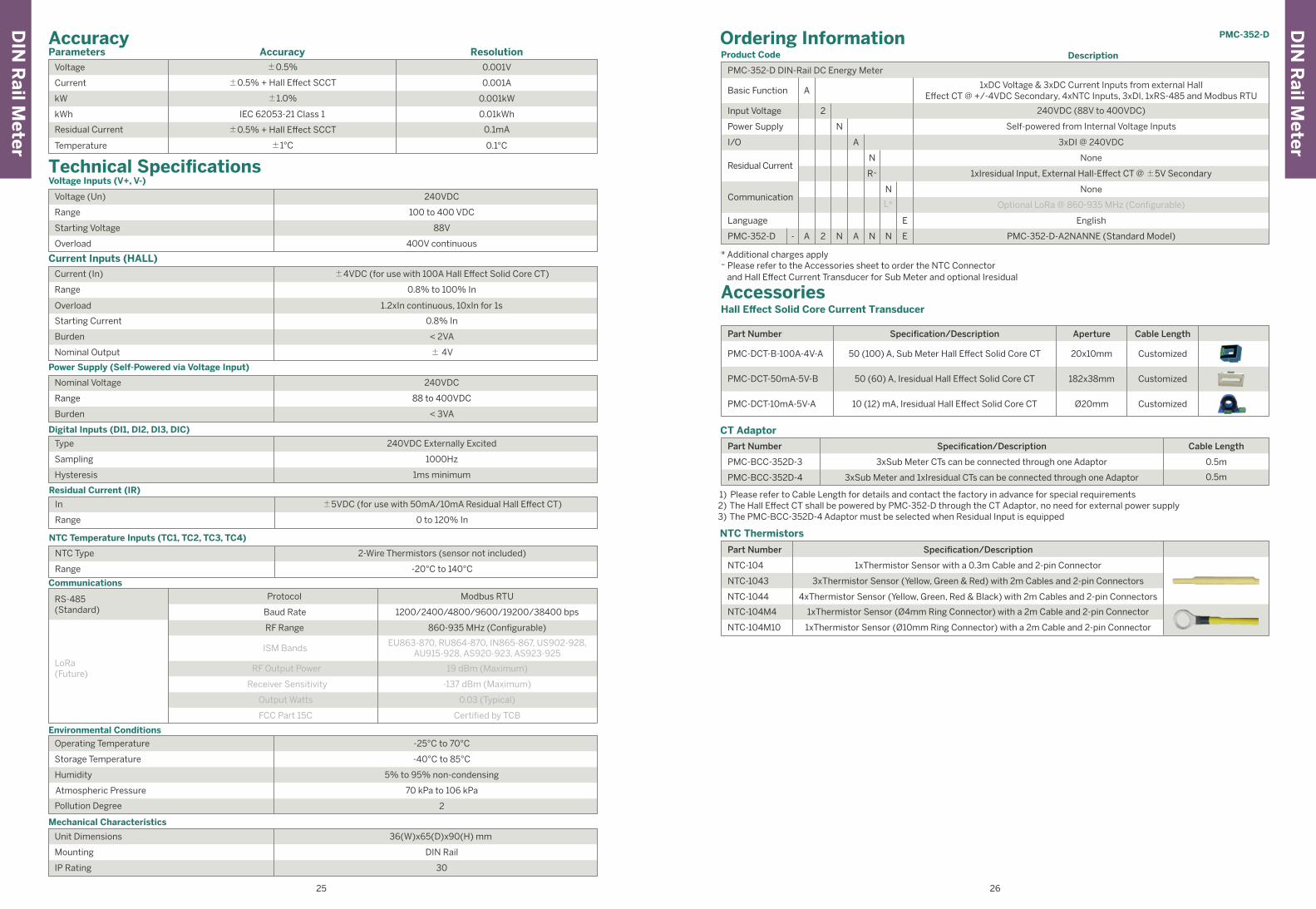
Parameters ResolutionAccuracyAccuracy
Voltage
kW
kWh
Current
Residual Current
0.001V
0.001kW
0.01kWh
0.001A
0.1mA
Temperature 0.1°C
±0.5%
±1.0%
IEC 62053-21 Class 1
±0.5% + Hall Effect SCCT
±0.5% + Hall Effect SCCT
±1°C
Current Inputs (HALL)
Current (In)
Overload
Starting Current
Range
Burden
±4VDC (for use with 100A Hall Effect Solid Core CT)
1.2xIn continuous, 10xIn for 1s
0.8% In
0.8% to 100% In
< 2VA
Nominal Output ± 4V
Technical SpecificationsVoltage Inputs (V+, V-)
Voltage (Un) 240VDC
Starting Voltage
Overload
88V
Range 100 to 400 VDC
400V continuous
Power Supply (Self-Powered via Voltage Input)
Nominal Voltage 240VDC
Burden < 3VA
Range 88 to 400VDC
Digital Inputs (DI1, DI2, DI3, DIC)
Type 240VDC Externally Excited
Hysteresis 1ms minimum
Sampling 1000Hz
NTC Temperature Inputs (TC1, TC2, TC3, TC4)
NTC Type 2-Wire Thermistors (sensor not included)
Range -20°C to 140°C
Residual Current (IR)
In ±5VDC (for use with 50mA/10mA Residual Hall Effect CT)
Range 0 to 120% In
RS-485(Standard)
LoRa(Future)
Modbus RTUProtocol
1200/2400/4800/9600/19200/38400 bps
860-935 MHz (Configurable)
EU863-870, RU864-870, IN865-867, US902-928,AU915-928, AS920-923, AS923-925
Baud Rate
RF Range
ISM Bands
Output Watts
FCC Part 15C
Receiver Sensitivity
RF Output Power
Communications
19 dBm (Maximum)
-137 dBm (Maximum)
0.03 (Typical)
Certified by TCB
Unit Dimensions 36(W)x65(D)x90(H) mm
IP Rating 30
Mounting DIN Rail
Mechanical Characteristics
1) Please refer to Cable Length for details and contact the factory in advance for special requirements2) The Hall Effect CT shall be powered by PMC-352-D through the CT Adaptor, no need for external power supply3) The PMC-BCC-352D-4 Adaptor must be selected when Residual Input is equipped
Ordering InformationProduct Code
Basic Function
Residual Current
Power Supply
Description
A
Communication
N
R~
N
L*
A
N
2Input Voltage
PMC-352-D DIN-Rail DC Energy Meter
None
3xDI @ 240VDC
1xIresidual Input, External Hall-Effect CT @ ±5V Secondary
None
Optional LoRa @ 860-935 MHz (Configurable)
1xDC Voltage & 3xDC Current Inputs from external HallEffect CT @ +/-4VDC Secondary, 4xNTC Inputs, 3xDI, 1xRS-485 and Modbus RTU
Self-powered from Internal Voltage Inputs
240VDC (88V to 400VDC)
E
PMC-352-D A- N A N N E2 PMC-352-D-A2NANNE (Standard Model)
EnglishLanguage
I/O
Operating Temperature -25°C to 70°C
Humidity
Pollution Degree
Atmospheric Pressure
5% to 95% non-condensing
Storage Temperature -40°C to 85°C
70 kPa to 106 kPa
2
Environmental Conditions
NTC Thermistors
CT Adaptor
NTC-104 1xThermistor Sensor with a 0.3m Cable and 2-pin Connector
3xThermistor Sensor (Yellow, Green & Red) with 2m Cables and 2-pin ConnectorsNTC-1043
NTC-1044 4xThermistor Sensor (Yellow, Green, Red & Black) with 2m Cables and 2-pin Connectors
NTC-104M4 1xThermistor Sensor (Ø4mm Ring Connector) with a 2m Cable and 2-pin Connector
NTC-104M10 1xThermistor Sensor (Ø10mm Ring Connector) with a 2m Cable and 2-pin Connector
Part Number Specification/Description
PMC-BCC-352D-3 3xSub Meter CTs can be connected through one Adaptor 0.5m
0.5m3xSub Meter and 1xIresidual CTs can be connected through one AdaptorPMC-BCC-352D-4
Part Number Specification/Description Cable Length
* Additional charges apply~ Please refer to the Accessories sheet to order the NTC Connector and Hall Effect Current Transducer for Sub Meter and optional Iresidual
AccessoriesHall Effect Solid Core Current Transducer
PMC-DCT-B-100A-4V-A 50 (100) A, Sub Meter Hall Effect Solid Core CT
50 (60) A, Iresidual Hall Effect Solid Core CTPMC-DCT-50mA-5V-B
Part Number Specification/Description
Customized20x10mm
182x38mm
PMC-DCT-10mA-5V-A 10 (12) mA, Iresidual Hall Effect Solid Core CT CustomizedØ20mm
Customized
Cable LengthAperture
25 26
Pan
el Meter
PMC-53A-E
Class (kWh)
Operating Temperature (ºC)
Dimensions (mm)
Display (Backlit)
True RMS Sampling Rate
Battery-backed Real-time Clock
General0.5S
-25 to 70
Dot-Matrix LCD(Backlit)
√
96(W)x96(H)x88(D)
64
I/O
4
2DO or(2 Opt.)SS
-
(2 Opt.)
(1 Opt.)
√
√
-
Digital Input (DI)
Pulse Counter
Mechanical DigitalOutput (DO)/Solid StateOutput (SS)
Analog Input (AI),0/4-20mA
Analog Output (AO),0/4-20mA
kWh & kvarh Pulse Output (LED)
kWh & kvarh Pulse Output
IRIG-B (GPS)
Communications
Protocol
RS-485 Port
Ethernet
Modbus RTU,Modbus TCP,
BACnet, DNP3.0,Ethernet Gateway,SNTP, SMTP, TFTP
1
1
Web Server √
Power QualityTHD Voltage & Current
TOHD Voltage & Current
TEHD Voltage & Current
K-Factor
Individual Harmonics
Voltage/Current Unbalance
Waveform Capture on Screen
Waveform Recording
Dip Swell Detection
Transient Detection
√
√
2nd - 31st
√
-
√
√
√
-
-
IEC 61000-4-30
2-150kHz Conducted Emission
-
-
MeasurementsULN per Phase & Avg.
ULL per Phase & Avg.
Current per Phase & Avg.
Neutral Current (Meas./Calc.)
Frequency
kW per Phase & Total
kvar per Phase & Total
kVA per Phase & Total
PF per Phase & Total
kWh Import/Export
kvarh Import/Export
kVAh Total
Demands & TOU
Maximum Demands
Setpoints
√
√
√
√
√
√
√
√
√
√
√
√
√
√
√
LogsSOE Log
PQ Log
Energy Log
Max./Min. Log
On-board Log Memory
100 entries
√
8MB
-
√
Features Summary
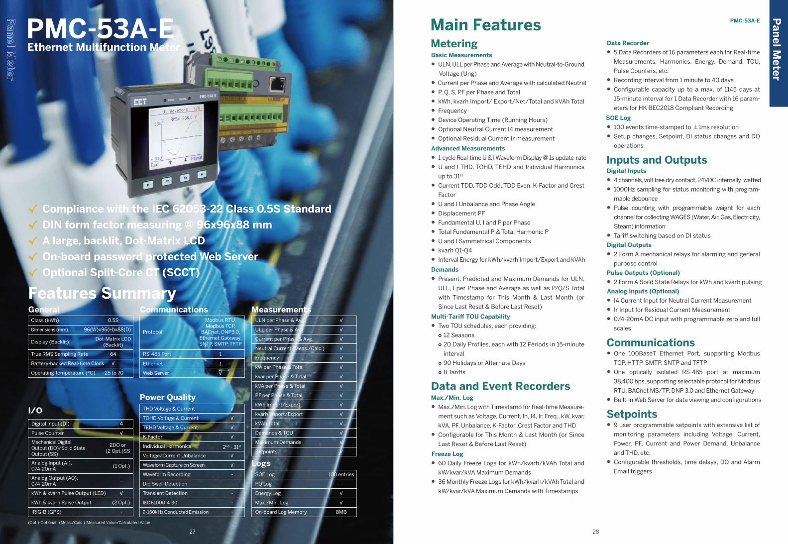
PMC-53A-E Ethernet Multifunction Meter
√ Compliance with the IEC 62053-22 Class 0.5S Standard
√ DIN form factor measuring @ 96x96x88 mm
√ A large, backlit, Dot-Matrix LCD
√ On-board password protected Web Server
√ Optional Split-Core CT (SCCT)
Main FeaturesMeteringBasic Measurements
• ULN, ULL per Phase and Average with Neutral-to-Ground
Voltage (Ung)
• Current per Phase and Average with calculated Neutral
• P, Q, S, PF per Phase and Total
• kWh, kvarh Import/ Export/Net/Total and kVAh Total
• Frequency
• Device Operating Time (Running Hours)
• Optional Neutral Current I4 measurement
• Optional Residual Current Ir measurement
Advanced Measurements
• 1-cycle Real-time U & I Waveform Display @ 1s update rate
• U and I THD, TOHD, TEHD and Individual Harmonics
up to 31st
• Current TDD, TDD Odd, TDD Even, K-Factor and Crest
Factor
• U and I Unbalance and Phase Angle
• Displacement PF
• Fundamental U, I and P per Phase
• Total Fundamental P & Total Harmonic P
• U and I Symmetrical Components
• kvarh Q1-Q4
• Interval Energy for kWh/kvarh Import/Export and kVAh
Demands
• Present, Predicted and Maximum Demands for ULN,
ULL, I per Phase and Average as well as P/Q/S Total
with Timestamp for This Month & Last Month (or
Since Last Reset & Before Last Reset)
Multi-Tariff TOU Capability
• Two TOU schedules, each providing:○ 12 Seasons○ 20 Daily Profiles, each with 12 Periods in 15-minute
interval○ 90 Holidays or Alternate Days○ 8 Tariffs
Data and Event RecordersMax./Min. Log
• Max./Min. Log with Timestamp for Real-time Measure-
ment such as Voltage, Current, In, I4, Ir, Freq., kW, kvar,
kVA, PF, Unbalance, K-Factor, Crest Factor and THD
• Configurable for This Month & Last Month (or Since
Last Reset & Before Last Reset)
Freeze Log
• 60 Daily Freeze Logs for kWh/kvarh/kVAh Total and
kW/kvar/kVA Maximum Demands
• 36 Monthly Freeze Logs for kWh/kvarh/kVAh Total and
kW/kvar/kVA Maximum Demands with Timestamps
Data Recorder
• 5 Data Recorders of 16 parameters each for Real-time
Measurements, Harmonics, Energy, Demand, TOU,
Pulse Counters, etc.
• Recording interval from 1 minute to 40 days
• Configurable capacity up to a max. of 1145 days at
15-minute interval for 1 Data Recorder with 16 param-
eters for HK BEC2018 Compliant Recording
SOE Log
• 100 events time-stamped to ±1ms resolution
• Setup changes, Setpoint, DI status changes and DO
operations
Inputs and OutputsDigital Inputs
• 4 channels, volt free dry contact, 24VDC internally wetted
• 1000Hz sampling for status monitoring with program-
mable debounce
• Pulse counting with programmable weight for each
channel for collecting WAGES (Water, Air, Gas, Electricity,
Steam) information
• Tariff switching based on DI status
Digital Outputs
• 2 Form A mechanical relays for alarming and general
purpose control
Pulse Outputs (Optional)
• 2 Form A Soild State Relays for kWh and kvarh pulsing
Analog Inputs (Optional)
• I4 Current Input for Neutral Current Measurement
• Ir Input for Residual Current Measurement
• 0/4-20mA DC input with programmable zero and full
scales
Communications• One 100BaseT Ethernet Port, supporting Modbus
TCP, HTTP, SMTP, SNTP and TFTP
• One optically isolated RS-485 port at maximum
38,400 bps, supporting selectable protocol for Modbus
RTU, BACnet MS/TP, DNP 3.0 and Ethernet Gateway
• Built-in Web Server for data viewing and configurations
Setpoints• 9 user programmable setpoints with extensive list of
monitoring parameters including Voltage, Current,
Power, PF, Current and Power Demand, Unbalance
and THD, etc.
• Configurable thresholds, time delays, DO and Alarm
Email triggers
(Opt.)-Optional (Meas./Calc.)-Measured Value/Calculated Value
2827
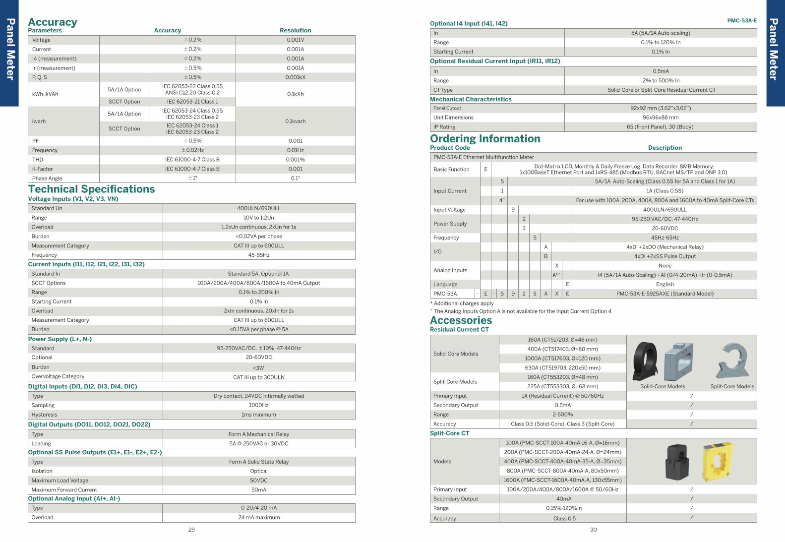
Pan
el Meter
Pan
el Meter
PMC-53A-E
AccessoriesResidual Current CT
Split-Core CT
Solid-Core Models
Split-Core Models
Primary Input
Secondary Output
Range
Accuracy
Models
Primary Input
Secondary Output
Range
Accuracy
160A (CT517203, Ø=46 mm)
400A (CT517403, Ø=80 mm)
630A (CT519703, 220x50 mm)
1000A (CT517603, Ø=120 mm)
160A (CT553203, Ø=48 mm)
225A (CT553303, Ø=68 mm) Split-Core ModelsSolid-Core Models
1A (Residual Current) @ 50/60Hz
0.5mA /
/
/
/
/
/
/
/
2-500%
400A (PMC-SCCT-400A-40mA-35-A, Ø=35mm)
800A (PMC-SCCT-800A-40mA-A, 80x50mm)
1600A (PMC-SCCT-1600A-40mA-A, 130x55mm)
100A/200A/400A/800A/1600A @ 50/60Hz
40mA
0.15%-120%In
Class 0.5
Class 0.5 (Solid-Core), Class 3 (Split-Core)
100A (PMC-SCCT-100A-40mA-16-A, Ø=16mm)
200A (PMC-SCCT-200A-40mA-24-A, Ø=24mm)
Ordering InformationProduct Code
PMC-53A-E Ethernet Multifunction Meter
Dot-Matrix LCD, Monthly & Daily Freeze Log, Data Recorder, 8MB Memory,1x100BaseT Ethernet Port and 1xRS-485 (Modbus RTU, BACnet MS/TP and DNP 3.0) Basic Function
Power Supply
Frequency
I/O
Analog Inputs
Language
PMC-53A
6DI + 2DO + 1AO (0-20mA or 4-20mA)
1A (Class 0.5S)
5A/1A Auto-Scaling (Class 0.5S for 5A and Class 1 for 1A)
Input Current
Input Voltage
Description
* Additional charges apply
^ The Analog Inputs Option A is not available for the Input Current Option 4
400ULN/690ULL
95-250 VAC/DC, 47-440Hz
45Hz-65Hz
English
4xDI +2xSS Pulse Output
4xDI +2xDO (Mechanical Relay)
None
I4 (5A/1A Auto-Scaling) +AI (0/4-20mA) +Ir (0-0.5mA)
PMC-53A-E-5925AXE (Standard Model)
E
5
5 E
E
9 25
5
1
For use with 100A, 200A, 400A, 800A and 1600A to 40mA Split-Core CTs4^
9
2
20-60VDC3
X
X
A*^
A
A
B
E- -
Panel Cutout
Unit Dimensions
IP Rating
Mechanical Characteristics92x92 mm (3.62”x3.62”)
96x96x88 mm
65 (Front Panel), 30 (Body)
In
Range
CT Type
Optional Residual Current Input (IR11, IR12)
0.5mA
2% to 500% In
Solid-Core or Split-Core Residual Current CT
Optional Analog Input (AI+, AI-)
Type
Overload
0-20/4-20 mA
24 mA maximum
29 30
Technical Specifications
400ULN/690ULL
Range
Overload
Burden
Measurement Category
Frequency
10V to 1.2Un
1.2xUn continuous, 2xUn for 1s
<0.02VA per phase
CAT III up to 600ULL
45-65Hz
Voltage Inputs (V1, V2, V3, VN)
Standard Un
Standard
Burden
Overvoltage Category
Power Supply (L+, N-)
95-250VAC/DC, ±10%, 47-440Hz
Optional 20-60VDC
<3W
CAT III up to 300ULN
Type
Sampling
Hysteresis
Digital Inputs (DI1, DI2, DI3, DI4, DIC)
Dry contact, 24VDC internally wetted
1000Hz
1ms minimum
Digital Outputs (DO11, DO12, DO21, DO22)
Type
Loading
Form A Mechanical Relay
5A @ 250VAC or 30VDC
Type
Isolation
Maximum Load Voltage
Maximum Forward Current
Optional SS Pulse Outputs (E1+, E1-, E2+, E2-)
Form A Solid State Relay
Optical
50VDC
50mA
Parameters Accuracy Resolution
Voltage
Current
I4 (measurement)
P, Q, S
kWh, kVAh 5A/1A Option
SCCT Option
5A/1A Option
SCCT Option
kvarh
Ir (measurement)
±0.2%
±0.2%
±0.2%
±0.5%
IEC 62053-21 Class 1
IEC 62053-22 Class 0.5SANSI C12.20 Class 0.2
IEC 62053-24 Class 0.5SIEC 62053-23 Class 2
IEC 62053-24 Class 1IEC 62053-23 Class 2
±0.5%
0.001V
0.001A
0.001A
0.001A
0.001kX
0.1kXh
0.1kvarh
Frequency
THD
K-Factor
PF
±0.02Hz
IEC 61000-4-7 Class B
IEC 61000-4-7 Class B
±0.5%
0.01Hz
0.001%
0.001
Phase Angle ±1° 0.1°
0.001
Accuracy
Range
Starting Current
Overload
Measurement Category
Burden
Current Inputs (I11, I12, I21, I22, I31, I32)
Standard 5A, Optional 1A
100A/200A/400A/800A/1600A to 40mA Output
0.1% to 200% In
0.1% In
2xIn continuous, 20xIn for 1s
CAT III up to 600ULL
<0.15VA per phase @ 5A
Standard In
SCCT Options
Range
Starting Current
Optional I4 Input (I41, I42)
5A (5A/1A Auto-scaling)
0.1% to 120% In
0.1% In
In
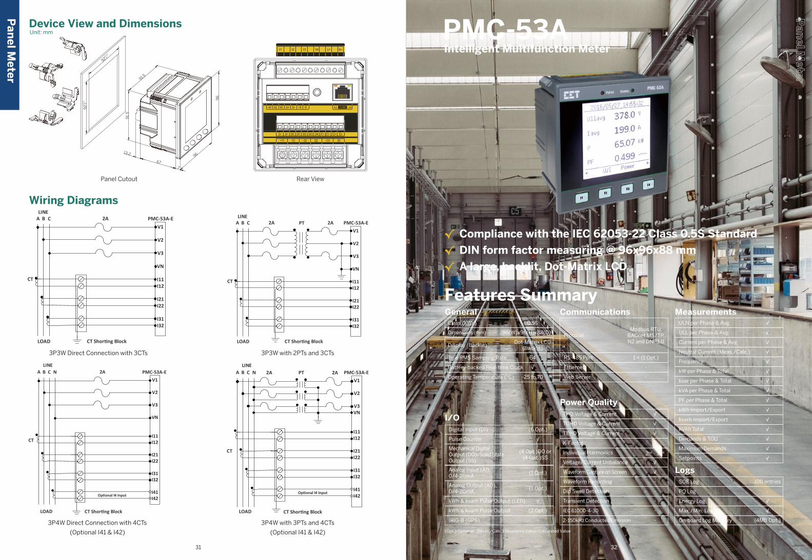
96
677
96
92
92
0+0.8
+0
.80
91.
5
91.5
13.2
Class (kWh)
Operating Temperature (ºC)
Dimensions (mm)
Display (Backlit)
True RMS Sampling Rate
Battery-backed Real-time Clock
General0.5S
-25 to 70
Dot-Matrix LCD(Backlit)
√
96(W)x96(H)x88(D)
64
I/O(6 Opt.)
(4 Opt.)DO or(4 Opt.)SS
(1 Opt.)
(2 Opt.)
(1 Opt.)
√
√
-
Digital Input (DI)
Pulse Counter
Mechanical DigitalOutput (DO)/Solid StateOutput (SS)
Analog Input (AI),0/4-20mA
Analog Output (AO),0/4-20mA
kWh & kvarh Pulse Output (LED)
kWh & kvarh Pulse Output
IRIG-B (GPS)
Communications
Protocol
Ethernet
Modbus RTU,BACnet MS/TP,N2 and DNP3.0
RS-485 Port 1 + (1 Opt.)
-
Web Server -
Power QualityTHD Voltage & Current
TOHD Voltage & Current
TEHD Voltage & Current
K-Factor
Individual Harmonics
Voltage/Current Unbalance
Waveform Capture on Screen
Waveform Recording
Dip Swell Detection
Transient Detection
√
√
2nd - 31st
√
-
√
√
√
-
-
IEC 61000-4-30
2-150kHz Conducted Emission
-
-
MeasurementsULN per Phase & Avg.
ULL per Phase & Avg.
Current per Phase & Avg.
Neutral Current (Meas./Calc.)
Frequency
kW per Phase & Total
kvar per Phase & Total
kVA per Phase & Total
PF per Phase & Total
kWh Import/Export
kvarh Import/Export
kVAh Total
Demands & TOU
Maximum Demands
Setpoints
√
√
√
√
√
√
√
√
√
√
√
√
√
√
√
LogsSOE Log
PQ Log
Energy Log
Max./Min. Log
On-board Log Memory
100 entries
√
(4MB Opt.)
-
√
Features Summary
√ Compliance with the IEC 62053-22 Class 0.5S Standard
√ DIN form factor measuring @ 96x96x88 mm
√ A large, backlit, Dot-Matrix LCD
PMC-53A Intelligent Multifunction Meter
Device View and DimensionsUnit: mm
Pan
el Meter
Wiring Diagrams
3P3W with 2PTs and 3CTs3P3W Direct Connection with 3CTs
3P4W Direct Connection with 4CTs
(Optional I41 & I42)
3P4W with 3PTs and 4CTs
(Optional I41 & I42)
Panel Cutout Rear View
(Opt.)-Optional (Meas./Calc.)-Measured Value/Calculated Value
31 32
PMC-53A-EV1
V2
V3
VN
I11I12
I21I22
I31I32
LOAD CT Shor�ng Block
A B CLINE
2A PT 2A
CT
PMC-53A-EV1
V2
V3
VN
I11I12
I21I22
I31I32
LOAD CT Shor�ng Block
A B CLINE
2A
CT
A B CLINE
PMC-53A-EV1
V2
V3
VN
I11I12
I21I22
I31I32
I41I42
2A
CT
LOAD CT Shor�ng Block
N
Op�onal I4 Input
A B CLINE
PMC-53A-EV1
V2
V3VN
I11I12
I21I22
I31I32
I41I42
CT
LOAD CT Shor�ng Block
N 2A 2APT
Op�onal I4 Input
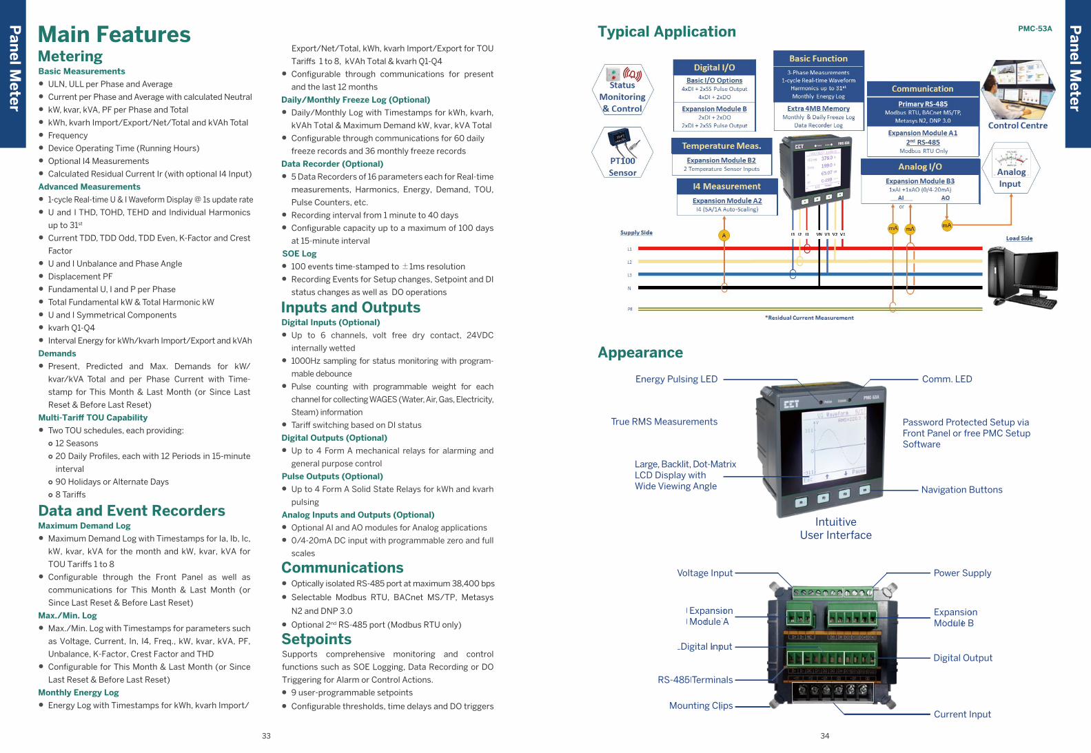
Pan
el Meter
Pan
el Meter
Typical Application
Appearance
Password Protected Setup via Front Panel or free PMC Setup Software
Energy Pulsing LED
Large, Backlit, Dot-MatrixLCD Display withWide Viewing Angle
IntuitiveUser Interface
Navigation Buttons
Comm. LED
True RMS Measurements
Voltage Input
Mounting ClipsMounting Clips
ExpansionModule AExpansionModule A
DI TerminalsDigital Input
Power Supply
RS-485 TerminalsRS-485 Terminals
ExpansionModule B
ExpansionModule B
DO TerminalsDigital Output
Current Input
PMC-53AMain FeaturesMeteringBasic Measurements
• ULN, ULL per Phase and Average
• Current per Phase and Average with calculated Neutral
• kW, kvar, kVA, PF per Phase and Total
• kWh, kvarh Import/Export/Net/Total and kVAh Total
• Frequency
• Device Operating Time (Running Hours)
• Optional I4 Measurements
• Calculated Residual Current Ir (with optional I4 Input)
Advanced Measurements
• 1-cycle Real-time U & I Waveform Display @ 1s update rate
• U and I THD, TOHD, TEHD and Individual Harmonics
up to 31st
• Current TDD, TDD Odd, TDD Even, K-Factor and Crest
Factor
• U and I Unbalance and Phase Angle
• Displacement PF
• Fundamental U, I and P per Phase
• Total Fundamental kW & Total Harmonic kW
• U and I Symmetrical Components
• kvarh Q1-Q4
• Interval Energy for kWh/kvarh Import/Export and kVAh
Demands
• Present, Predicted and Max. Demands for kW/
kvar/kVA Total and per Phase Current with Time-
stamp for This Month & Last Month (or Since Last
Reset & Before Last Reset)
Multi-Tariff TOU Capability
• Two TOU schedules, each providing:○ 12 Seasons○ 20 Daily Profiles, each with 12 Periods in 15-minute
interval○ 90 Holidays or Alternate Days○ 8 Tariffs
Data and Event RecordersMaximum Demand Log
• Maximum Demand Log with Timestamps for Ia, Ib, Ic,
kW, kvar, kVA for the month and kW, kvar, kVA for
TOU Tariffs 1 to 8
• Configurable through the Front Panel as well as
communications for This Month & Last Month (or
Since Last Reset & Before Last Reset)
Max./Min. Log
• Max./Min. Log with Timestamps for parameters such
as Voltage, Current, In, I4, Freq., kW, kvar, kVA, PF,
Unbalance, K-Factor, Crest Factor and THD
• Configurable for This Month & Last Month (or Since
Last Reset & Before Last Reset)
Monthly Energy Log
• Energy Log with Timestamps for kWh, kvarh Import/
33 34
Export/Net/Total, kWh, kvarh Import/Export for TOU
Tariffs 1 to 8, kVAh Total & kvarh Q1-Q4
• Configurable through communications for present
and the last 12 months
Daily/Monthly Freeze Log (Optional)
• Daily/Monthly Log with Timestamps for kWh, kvarh,
kVAh Total & Maximum Demand kW, kvar, kVA Total
• Configurable through communications for 60 daily
freeze records and 36 monthly freeze records
Data Recorder (Optional)
• 5 Data Recorders of 16 parameters each for Real-time
measurements, Harmonics, Energy, Demand, TOU,
Pulse Counters, etc.
• Recording interval from 1 minute to 40 days
• Configurable capacity up to a maximum of 100 days
at 15-minute interval
SOE Log
• 100 events time-stamped to ±1ms resolution
• Recording Events for Setup changes, Setpoint and DI
status changes as well as DO operations
Inputs and OutputsDigital Inputs (Optional)
• Up to 6 channels, volt free dry contact, 24VDC
internally wetted
• 1000Hz sampling for status monitoring with program-
mable debounce
• Pulse counting with programmable weight for each
channel for collecting WAGES (Water, Air, Gas, Electricity,
Steam) information
• Tariff switching based on DI status
Digital Outputs (Optional)
• Up to 4 Form A mechanical relays for alarming and
general purpose control
Pulse Outputs (Optional)
• Up to 4 Form A Solid State Relays for kWh and kvarh
pulsing
Analog Inputs and Outputs (Optional)
• Optional AI and AO modules for Analog applications
• 0/4-20mA DC input with programmable zero and full
scales
Communications• Optically isolated RS-485 port at maximum 38,400 bps
• Selectable Modbus RTU, BACnet MS/TP, Metasys
N2 and DNP 3.0
• Optional 2nd RS-485 port (Modbus RTU only)
SetpointsSupports comprehensive monitoring and control
functions such as SOE Logging, Data Recording or DO
Triggering for Alarm or Control Actions.
• 9 user-programmable setpoints
• Configurable thresholds, time delays and DO triggers
-
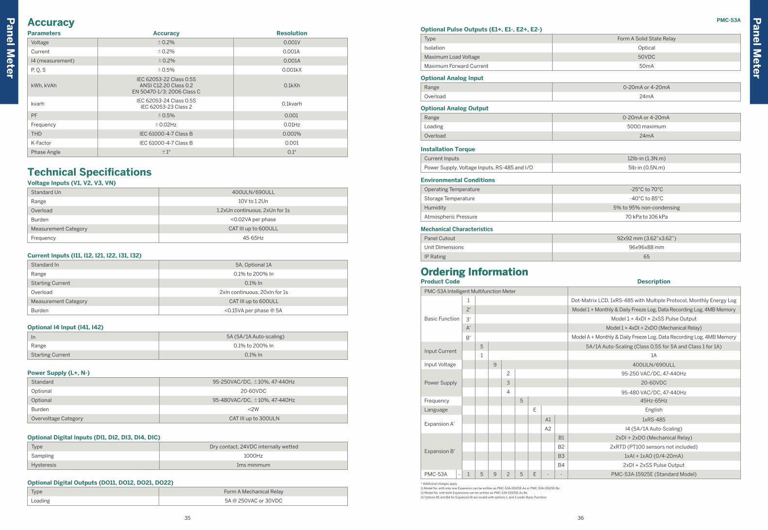
Technical SpecificationsVoltage Inputs (V1, V2, V3, VN)
400ULN/690ULL
Range
Overload
Burden
Measurement Category
Frequency
10V to 1.2Un
1.2xUn continuous, 2xUn for 1s
<0.02VA per phase
CAT III up to 600ULL
45-65Hz
Standard Un
Current Inputs (I11, I12, I21, I22, I31, I32)
0.1% to 200% In
0.1% In
2xIn continuous, 20xIn for 1s
CAT III up to 600ULL
<0.15VA per phase @ 5A
Standard In
Range
Starting Current
Overload
Measurement Category
Burden
5A, Optional 1A
Optional I4 Input (I41, I42)
0.1% to 200% In
0.1% In
In
Range
Starting Current
5A (5A/1A Auto-scaling)
Optional Digital Inputs (DI1, DI2, DI3, DI4, DIC)
Type
Sampling
Hysteresis
Dry contact, 24VDC internally wetted
1000Hz
1ms minimum
Optional Digital Outputs (DO11, DO12, DO21, DO22)
5A @ 250VAC or 30VDC
Type
Loading
Form A Mechanical Relay
Power Supply (L+, N-)
95-250VAC/DC, ±10%, 47-440Hz
20-60VDC
95-480VAC/DC, ±10%, 47-440Hz
<2W
CAT III up to 300ULN
Standard
Optional
Optional
Burden
Overvoltage Category
Parameters
Voltage ±0.2%
±0.2%
±0.2%
±0.5%
IEC 62053-24 Class 0.5SIEC 62053-23 Class 2
IEC 62053-22 Class 0.5SANSI C12.20 Class 0.2
EN 50470-1/3: 2006 Class C
Current
I4 (measurement)
P, Q, S
kWh, kVAh
kvarh
0.001V
0.001A
0.001A
0.001kX
0.1kXh
0.1kvarh
±0.5%
±0.02Hz
IEC 61000-4-7 Class B
IEC 61000-4-7 Class B
±1°
PF
Frequency
THD
K-Factor
Phase Angle
0.001
0.01Hz
0.001%
0.001
0.1°
ResolutionAccuracy
AccuracyP
anel M
eter
Ordering InformationOrdering InformationProduct Code Description
* Additional charges apply
1) Model No. with only one Expansion can be written as PMC-53A-15925E-Ax or PMC-53A-15925E-Bx
2) Model No. with both Expansions can be written as PMC-53A-15925E-Ax-Bx
3) Options B1 and B4 for Expansion B are invalid with options 1, and 2 under Basic Function
PMC-53A Intelligent Multifunction Meter
Dot-Matrix LCD, 1xRS-485 with Multiple Protocol, Monthly Energy Log
Model 1 + Monthly & Daily Freeze Log, Data Recording Log, 4MB Memory2*
Basic Function
400ULN/690ULLInput Voltage
45Hz-65HzFrequency
5A/1A Auto-Scaling (Class 0.5S for 5A and Class 1 for 1A)Input Current
EnglishLanguage
Model 1 + 4xDI + 2xDO (Mechanical Relay)A*
Model A + Monthly & Daily Freeze Log, Data Recording Log, 4MB MemoryB*
Model 1 + 4xDI + 2xSS Pulse Output3*
1A
Expansion B*
2xDI + 2xDO (Mechanical Relay)
2xRTD (PT100 sensors not included)
1xAI + 1xAO (0/4-20mA)
2xDI + 2xSS Pulse Output
95-250 VAC/DC, 47-440Hz
20-60VDC
95-480 VAC/DC, 47-440Hz
Power Supply
1xRS-485
I4 (5A/1A Auto-Scaling)Expansion A*
PMC-53A-15925E (Standard Model)1- 5 9 2 5 E - -PMC-53A
1
5
1
9
2
3
4
5
E
A1
A2
B1
B2
B3
B4
Optional Pulse Outputs (E1+, E1-, E2+, E2-)
Optical
Type
Isolation
Maximum Load Voltage
Maximum Forward Current
50VDC
50mA
Form A Solid State Relay
Environmental Conditions
-40°C to 85°C
5% to 95% non-condensing
70 kPa to 106 kPa
Operating Temperature
Storage Temperature
Humidity
Atmospheric Pressure
-25°C to 70°C
Mechanical Characteristics
96x96x88 mm
65
Panel Cutout
Unit Dimensions
IP Rating
92x92 mm (3.62”x3.62”)
Optional Analog Output
500Ω maximum
24mA
Range
Loading
Overload
0-20mA or 4-20mA
Installation Torque
Current Inputs
Power Supply, Voltage Inputs, RS-485 and I/O
12Ib-in (1.3N.m)
5Ib-in (0.5N.m)
Optional Analog Input
Range
Overload
0-20mA or 4-20mA
24mA
Pan
el Meter
PMC-53A
35 36
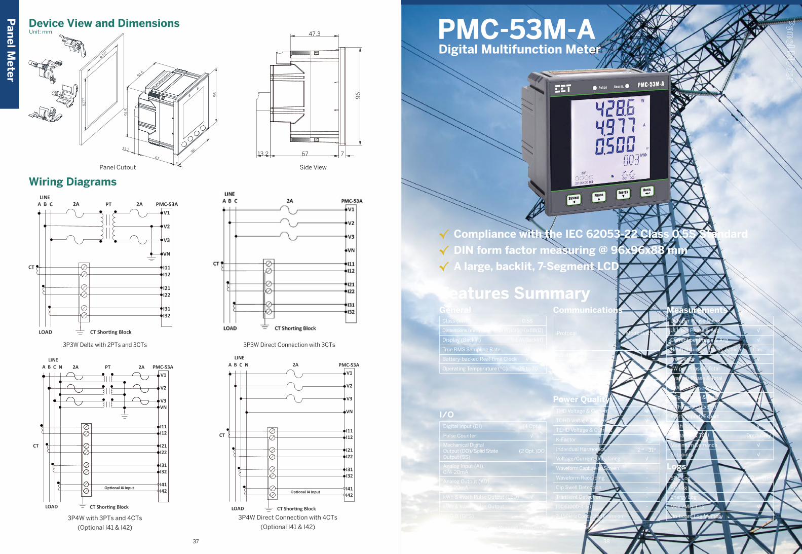
96
677
96
92
92
0+0.8
+0
.80
91.
5
91.5
13.2
47.3
96
67 713.2
Class (kWh)
Operating Temperature (ºC)
Dimensions (mm)
Display (Backlit)
True RMS Sampling Rate
Battery-backed Real-time Clock
General0.5S
-25 to 70
B&W(Backlit)
√
96(W)x96(H)x88(D)
64
I/O(4 Opt.)
(2 Opt.)DO
-
-
-
√
√
-
Digital Input (DI)
Pulse Counter
Mechanical DigitalOutput (DO)/Solid StateOutput (SS)
Analog Input (AI),0/4-20mA
Analog Output (AO),0/4-20mA
kWh & kvarh Pulse Output (LED)
kWh & kvarh Pulse Output
IRIG-B (GPS)
Communications
Protocol
RS-485 Port
Ethernet
Modbus RTU
1
-
Web Server -
Power QualityTHD Voltage & Current
TOHD Voltage & Current
TEHD Voltage & Current
K-Factor
Individual Harmonics
Voltage/Current Unbalance
Waveform Capture on Screen
Waveform Recording
Dip Swell Detection
Transient Detection
√
√
2nd - 31st
-
-
√
√
√
-
-
IEC 61000-4-30
2-150kHz Conducted Emission
-
-
MeasurementsULN per Phase & Avg.
ULL per Phase & Avg.
Current per Phase & Avg.
Neutral Current (Meas./Calc.)
Frequency
kW per Phase & Total
kvar per Phase & Total
kVA per Phase & Total
PF per Phase & Total
kWh Import/Export
kvarh Import/Export
kVAh Total
Demands & TOU
Maximum Demands
Setpoints
√
√
√
√
√
√
Dmd. Only
√
√
Calc.
√
√
√
√
√
LogsSOE Log
PQ Log
Energy Log
Max./Min. Log
On-board Log Memory
100 entries
-
-
-
√
Features Summary
√ Compliance with the IEC 62053-22 Class 0.5S Standard
√ DIN form factor measuring @ 96x96x88 mm
√ A large, backlit, 7-Segment LCD
PMC-53M-A Digital Multifunction Meter
Side ViewPanel Cutout
Device View and DimensionsUnit: mm
Wiring Diagrams
3P3W Direct Connection with 3CTs
3P4W Direct Connection with 4CTs
(Optional I41 & I42)
3P3W Delta with 2PTs and 3CTs
3P4W with 3PTs and 4CTs
(Optional I41 & I42)
Pan
el Meter
(Opt.)-Optional (Meas./Calc.)-Measured Value/Calculated Value (Dmd.)-Demand
37 38
PMC-53AV1
V2
V3
VN
I11I12
I21I22
I31I32
LOAD CT Shor�ng Block
A B CLINE
2A PT 2A
CT
A B CLINE
PMC-53AV1
V2
V3VN
I11I12
I21I22
I31I32
I41I42
CT
LOAD CT Shor�ng Block
N 2A 2APT
Op�onal I4 Input
A B CLINE
PMC-53AV1
V2
V3
VN
I11I12
I21I22
I31I32
I41I42
2A
CT
LOAD CT Shor�ng Block
N
Op�onal I4 Input
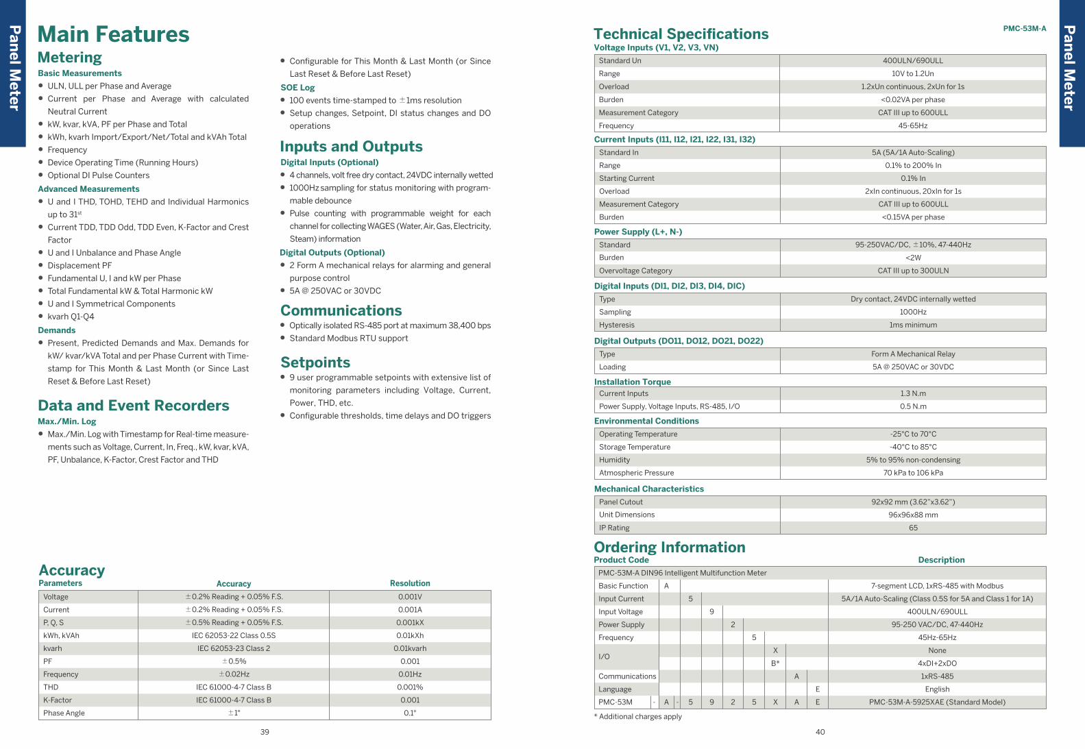
PMC-53M-A
Ordering InformationProduct Code
PMC-53M-A DIN96 Intelligent Multifunction Meter
English
PMC-53M-A-5925XAE (Standard Model)A- - 5 5 X A E9 2
None
4xDI+2xDO
1xRS-485
5A/1A Auto-Scaling (Class 0.5S for 5A and Class 1 for 1A)
400ULN/690ULL
95-250 VAC/DC, 47-440Hz
45Hz-65Hz
7-segment LCD, 1xRS-485 with Modbus
Description
* Additional charges apply
Basic Function
Power Supply
Frequency
Communications
Language
I/O
PMC-53M
Input Current
Input Voltage
5
9
2
5
X
A
B*
A
E
Technical SpecificationsVoltage Inputs (V1, V2, V3, VN)
Standard Un
Range
Overload
Burden
Measurement Category
Frequency
10V to 1.2Un
1.2xUn continuous, 2xUn for 1s
<0.02VA per phase
CAT III up to 600ULL
45-65Hz
400ULN/690ULL
Current Inputs (I11, I12, I21, I22, I31, I32)
5A (5A/1A Auto-Scaling)
0.1% to 200% In
0.1% In
2xIn continuous, 20xIn for 1s
CAT III up to 600ULL
<0.15VA per phase
Standard In
Range
Starting Current
Overload
Measurement Category
Burden
Power Supply (L+, N-)
95-250VAC/DC, ±10%, 47-440Hz
<2W
CAT III up to 300ULN
Standard
Burden
Overvoltage Category
Digital Inputs (DI1, DI2, DI3, DI4, DIC)
Dry contact, 24VDC internally wetted
1000Hz
1ms minimum
Type
Sampling
Hysteresis
Panel Cutout
Unit Dimensions
IP Rating
Mechanical Characteristics
92x92 mm (3.62”x3.62”)
96x96x88 mm
65
Environmental Conditions
-25°C to 70°C
-40°C to 85°C
5% to 95% non-condensing
70 kPa to 106 kPa
Operating Temperature
Storage Temperature
Humidity
Atmospheric Pressure
Digital Outputs (DO11, DO12, DO21, DO22)
Form A Mechanical Relay
5A @ 250VAC or 30VDC
Type
Loading
Power Supply, Voltage Inputs, RS-485, I/O
Installation Torque1.3 N.m
0.5 N.m
Current Inputs
Parameters
±0.2% Reading + 0.05% F.S.
±0.5% Reading + 0.05% F.S.
IEC 62053-22 Class 0.5S
IEC 62053-23 Class 2
±0.5%
±0.02Hz
IEC 61000-4-7 Class B
IEC 61000-4-7 Class B
±1°
0.001A
0.001kX
0.01kXh
0.01kvarh
0.001
0.01Hz
0.001%
0.001
0.1°
ResolutionAccuracyAccuracy
Voltage
Current
P, Q, S
kWh, kVAh
kvarh
PF
Frequency
THD
K-Factor
Phase Angle
±0.2% Reading + 0.05% F.S. 0.001V
Main FeaturesP
anel M
eter
Pan
el Meter
MeteringBasic Measurements
• ULN, ULL per Phase and Average
• Current per Phase and Average with calculated
Neutral Current
• kW, kvar, kVA, PF per Phase and Total
• kWh, kvarh Import/Export/Net/Total and kVAh Total
• Frequency
• Device Operating Time (Running Hours)
• Optional DI Pulse Counters
Advanced Measurements
• U and I THD, TOHD, TEHD and Individual Harmonics
up to 31st
• Current TDD, TDD Odd, TDD Even, K-Factor and Crest
Factor
• U and I Unbalance and Phase Angle
• Displacement PF
• Fundamental U, I and kW per Phase
• Total Fundamental kW & Total Harmonic kW
• U and I Symmetrical Components
• kvarh Q1-Q4
Demands
• Present, Predicted Demands and Max. Demands for
kW/ kvar/kVA Total and per Phase Current with Time-
stamp for This Month & Last Month (or Since Last
Reset & Before Last Reset)
Data and Event RecordersMax./Min. Log
• Max./Min. Log with Timestamp for Real-time measure-
ments such as Voltage, Current, In, Freq., kW, kvar, kVA,
PF, Unbalance, K-Factor, Crest Factor and THD
• Configurable for This Month & Last Month (or Since
Last Reset & Before Last Reset)
SOE Log
• 100 events time-stamped to ±1ms resolution
• Setup changes, Setpoint, DI status changes and DO
operations
Inputs and OutputsDigital Inputs (Optional)
• 4 channels, volt free dry contact, 24VDC internally wetted
• 1000Hz sampling for status monitoring with program-
mable debounce
• Pulse counting with programmable weight for each
channel for collecting WAGES (Water, Air, Gas, Electricity,
Steam) information
Digital Outputs (Optional)
• 2 Form A mechanical relays for alarming and general
purpose control
• 5A @ 250VAC or 30VDC
Communications• Optically isolated RS-485 port at maximum 38,400 bps
• Standard Modbus RTU support
Setpoints• 9 user programmable setpoints with extensive list of
monitoring parameters including Voltage, Current,
Power, THD, etc.
• Configurable thresholds, time delays and DO triggers
4039
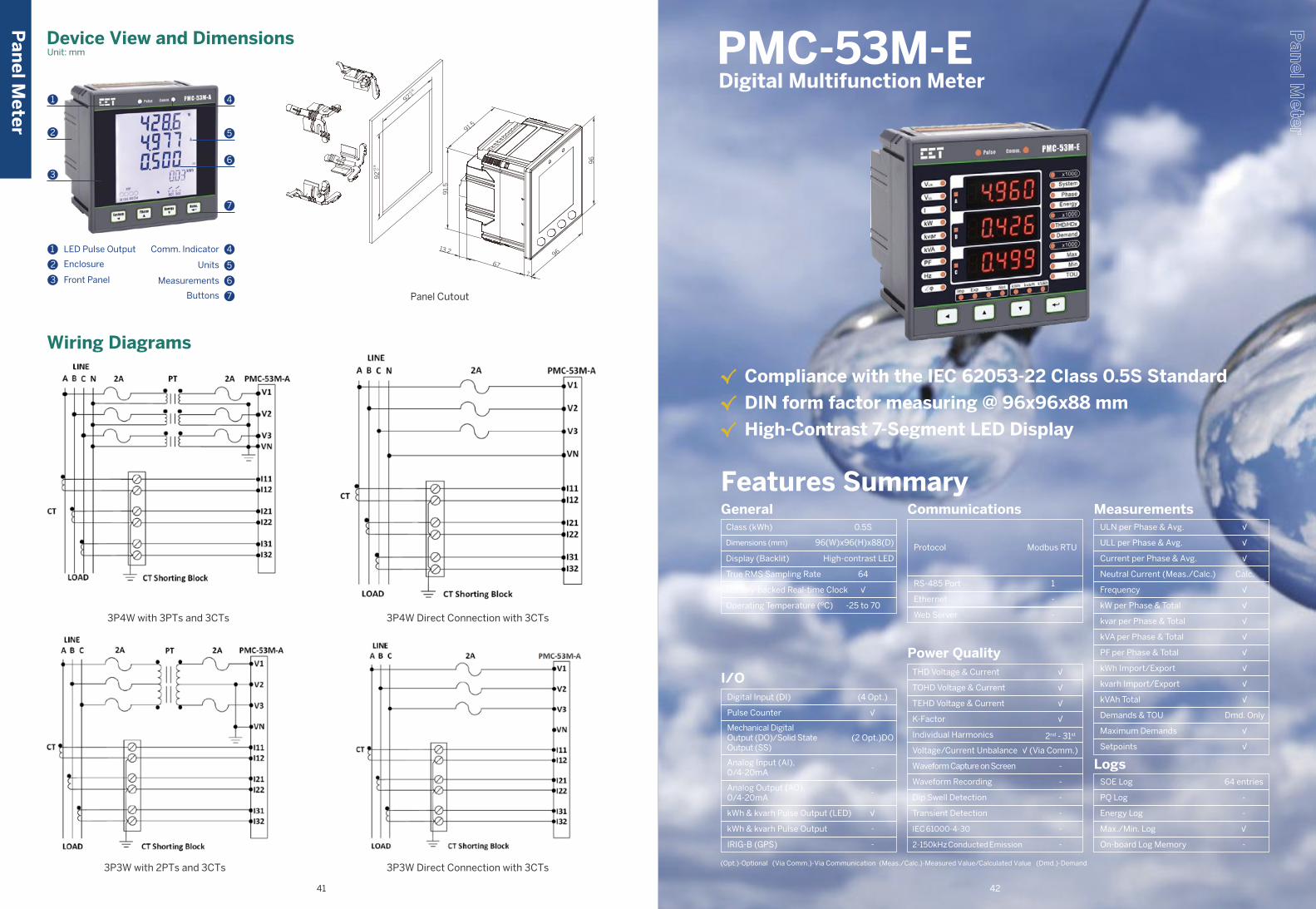
96
677
96
92
92
0+0.8
+0
.80
91.
5
91.5
13.2
Class (kWh)
Operating Temperature (ºC)
Dimensions (mm)
Display (Backlit)
True RMS Sampling Rate
Battery-backed Real-time Clock
General0.5S
-25 to 70
High-contrast LED
√
96(W)x96(H)x88(D)
64
I/O(4 Opt.)
(2 Opt.)DO
-
-
-
√
√
-
Digital Input (DI)
Pulse Counter
Mechanical DigitalOutput (DO)/Solid StateOutput (SS)
Analog Input (AI),0/4-20mA
Analog Output (AO),0/4-20mA
kWh & kvarh Pulse Output (LED)
kWh & kvarh Pulse Output
IRIG-B (GPS)
Communications
Protocol
RS-485 Port
Ethernet
Modbus RTU
1
-
Web Server -
Power QualityTHD Voltage & Current
TOHD Voltage & Current
TEHD Voltage & Current
K-Factor
Individual Harmonics
Voltage/Current Unbalance
Waveform Capture on Screen
Waveform Recording
Dip Swell Detection
Transient Detection
√
√
2nd - 31st
-
-
√
√
√ (Via Comm.)
-
-
IEC 61000-4-30
2-150kHz Conducted Emission
-
-
MeasurementsULN per Phase & Avg.
ULL per Phase & Avg.
Current per Phase & Avg.
Neutral Current (Meas./Calc.)
Frequency
kW per Phase & Total
kvar per Phase & Total
kVA per Phase & Total
PF per Phase & Total
kWh Import/Export
kvarh Import/Export
kVAh Total
Demands & TOU
Maximum Demands
Setpoints
√
√
√
√
√
√
Dmd. Only
√
√
Calc.
√
√
√
√
√
LogsSOE Log
PQ Log
Energy Log
Max./Min. Log
On-board Log Memory
64 entries
-
-
-
√
Features Summary
√ Compliance with the IEC 62053-22 Class 0.5S Standard
√ DIN form factor measuring @ 96x96x88 mm
√ High-Contrast 7-Segment LED Display
PMC-53M-E Digital Multifunction Meter
Panel Cutout
1 4
5
6
7
Comm. Indicator 4
Units 5
Measurements 6
Buttons 7
2
3
LED Pulse Output
Enclosure
Front Panel
1
2
3
Device View and DimensionsUnit: mm
3P4W with 3PTs and 3CTs 3P4W Direct Connection with 3CTs
3P3W with 2PTs and 3CTs 3P3W Direct Connection with 3CTs
Wiring Diagrams
Pan
el Meter
(Opt.)-Optional (Via Comm.)-Via Communication (Meas./Calc.)-Measured Value/Calculated Value (Dmd.)-Demand
41 42
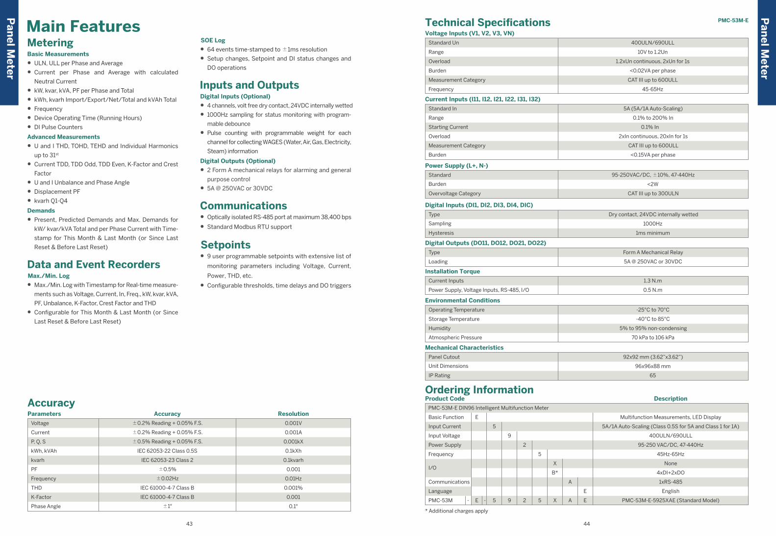
Technical SpecificationsVoltage Inputs (V1, V2, V3, VN)
Current Inputs (I11, I12, I21, I22, I31, I32)
Power Supply (L+, N-)
Digital Inputs (DI1, DI2, DI3, DI4, DIC)
Mechanical Characteristics
Digital Outputs (DO11, DO12, DO21, DO22)
Installation Torque
Environmental Conditions
Standard Un
Range
Overload
Burden
Measurement Category
Frequency
10V to 1.2Un
1.2xUn continuous, 2xUn for 1s
<0.02VA per phase
CAT III up to 600ULL
45-65Hz
400ULN/690ULL
5A (5A/1A Auto-Scaling)
0.1% to 200% In
0.1% In
2xIn continuous, 20xIn for 1s
CAT III up to 600ULL
<0.15VA per phase
Standard In
Range
Starting Current
Overload
Measurement Category
Burden
95-250VAC/DC, ±10%, 47-440Hz
<2W
CAT III up to 300ULN
Standard
Burden
Overvoltage Category
Dry contact, 24VDC internally wetted
1000Hz
1ms minimum
Type
Sampling
Hysteresis
Panel Cutout
Unit Dimensions
IP Rating
92x92 mm (3.62”x3.62”)
96x96x88 mm
65
-25°C to 70°C
-40°C to 85°C
5% to 95% non-condensing
70 kPa to 106 kPa
Operating Temperature
Storage Temperature
Humidity
Atmospheric Pressure
Form A Mechanical Relay
5A @ 250VAC or 30VDC
Type
Loading
Power Supply, Voltage Inputs, RS-485, I/O
1.3 N.m
0.5 N.m
Current Inputs
Parameters
Voltage ±0.2% Reading + 0.05% F.S.
±0.2% Reading + 0.05% F.S.
±0.5% Reading + 0.05% F.S.
IEC 62053-22 Class 0.5S
±0.5%
IEC 62053-23 Class 2
±0.02Hz
IEC 61000-4-7 Class B
IEC 61000-4-7 Class B
±1°
Current
P, Q, S
kWh, kVAh
kvarh
PF
Frequency
THD
K-Factor
Phase Angle
0.001V
0.001A
0.001kX
0.1kXh
0.1kvarh
0.001
0.01Hz
0.001%
0.001
0.1°
ResolutionAccuracy
Accuracy
Main Features
Ordering InformationProduct Code
PMC-53M-E DIN96 Intelligent Multifunction Meter
English
PMC-53M-E-5925XAE (Standard Model)E- - 5 5 X A E9 2
None
4xDI+2xDO
1xRS-485
5A/1A Auto-Scaling (Class 0.5S for 5A and Class 1 for 1A)
400ULN/690ULL
95-250 VAC/DC, 47-440Hz
45Hz-65Hz
Multifunction Measurements, LED Display
Description
* Additional charges apply
Basic Function
Power Supply
Frequency
Communications
Language
I/O
PMC-53M
Input Current
Input Voltage
5
9
2
5
X
A
B*
E
E
PMC-53M-EP
anel M
eter
Pan
el Meter
MeteringBasic Measurements
• ULN, ULL per Phase and Average
• Current per Phase and Average with calculated
Neutral Current
• kW, kvar, kVA, PF per Phase and Total
• kWh, kvarh Import/Export/Net/Total and kVAh Total
• Frequency
• Device Operating Time (Running Hours)
• DI Pulse Counters
Advanced Measurements
• U and I THD, TOHD, TEHD and Individual Harmonics
up to 31st
• Current TDD, TDD Odd, TDD Even, K-Factor and Crest
Factor
• U and I Unbalance and Phase Angle
• Displacement PF
• kvarh Q1-Q4
Demands
• Present, Predicted Demands and Max. Demands for
kW/ kvar/kVA Total and per Phase Current with Time-
stamp for This Month & Last Month (or Since Last
Reset & Before Last Reset)
Data and Event RecordersMax./Min. Log
• Max./Min. Log with Timestamp for Real-time measure-
ments such as Voltage, Current, In, Freq., kW, kvar, kVA,
PF, Unbalance, K-Factor, Crest Factor and THD
• Configurable for This Month & Last Month (or Since
Last Reset & Before Last Reset)
SOE Log
• 64 events time-stamped to ±1ms resolution
• Setup changes, Setpoint and DI status changes and
DO operations
Inputs and OutputsDigital Inputs (Optional)
• 4 channels, volt free dry contact, 24VDC internally wetted
• 1000Hz sampling for status monitoring with program-
mable debounce
• Pulse counting with programmable weight for each
channel for collecting WAGES (Water, Air, Gas, Electricity,
Steam) information
Digital Outputs (Optional)
• 2 Form A mechanical relays for alarming and general
purpose control
• 5A @ 250VAC or 30VDC
Communications• Optically isolated RS-485 port at maximum 38,400 bps
• Standard Modbus RTU support
Setpoints• 9 user programmable setpoints with extensive list of
monitoring parameters including Voltage, Current,
Power, THD, etc.
• Configurable thresholds, time delays and DO triggers
43 44

Device View and DimensionsUnit: mm
Features Summary
1
-
64
Class (kWh)
Operating Temperature (ºC)
Dimensions (mm)
Display (Backlit)
True RMS Sampling Rate
Battery-backed Real-time Clock
General
-25 to 70
B&W(Backlit )/LED
72(W)x72(H)x76.8(D)
(2 Opt.)
(2 Opt.)DO
(1 Opt.)
-
-
-
√
-
I/ODigital Input (DI)
Pulse Counter
Mechanical DigitalOutput (DO)/Solid StateOutput (SS)
Analog Input (AI),0/4-20mA
Analog Output (AO),0/4-20mA
kWh & kvarh Pulse Output (LED)
kWh & kvarh Pulse Output
IRIG-B (GPS)
Communications
Protocol
RS-485 Port
Ethernet
Modbus RTU
1
-
Web Server -
Power QualityTHD Voltage & Current
TOHD Voltage & Current
TEHD Voltage & Current
K-Factor
Individual Harmonics
Voltage/Current Unbalance
Waveform Capture on Screen
Waveform Recording
Dip Swell Detection
Transient Detection
√
√
2nd - 31st
-
-
√
√
√
-
-
IEC 61000-4-30
2-150kHz Conducted Emission
-
-
MeasurementsULN per Phase & Avg.
ULL per Phase & Avg.
Current per Phase & Avg.
Neutral Current (Meas./Calc.)
Frequency
kW per Phase & Total
kvar per Phase & Total
kVA per Phase & Total
PF per Phase & Total
kWh Import/Export
kvarh Import/Export
kVAh Total
Demands & TOU
Maximum Demands
Setpoints
√
√
√
√
√
√
√
√
√
Calc.
√
√
√
√
√
LogsSOE Log
PQ Log
Energy Log
Max./Min. Log
On-board Log Memory
16 entries
-
-
-
-
PMC-D726M Digital Multifunction Meter
√ Compliance with the IEC 62053-21 Class 1 kWh Accuracy
√ DIN size @ 72x72x71.8 mm (LCD), @ 72x72x76.8 mm (LED)
√ 4-digit, backlit LCD or High-Contrast LED Display
√ Optional Split-Core CT (SCCT)
Wiring Diagrams
3P3W Delta with 2PTs and 3CTs 3P3W Direct Connection with 3CTs
3P4W with 3PTs and 3CTs 3P4W Direct Connection with 3CTs
92
92
0+0.8
+0
.80
91.
5
91.5
96
677
96
13.2
61
72
3
84
95
12
34
5
EnclosureLED Pulse Output
Front PanelPhase Indicator
Energy Indicators
7Measurements6Comm. Indicator
8Parameters9Buttons
Panel Cutout
Pan
el Meter
(Opt.)-Optional (Meas./Calc.)-Measured Value/Calculated Value
45 46

PMC-D726M
Technical Specifications
Range
Starting Voltage
PT Ratio
Overload
Burden
Frequency
Voltage Inputs (V1, V2, V3, VN)
Standard
Optional Input
CT Ratio
Optional SCCT Input
Range
Starting Current
Overload
Burden
Current Inputs (I11, I12, I21, I22, I31, I32)
Standard Input
Standard
Burden
Power Supply (L/+, N/-)
Digital Outputs (DO11, DO12, DO21, DO22)
Type
Sampling
Hysteresis
Digital Inputs (DI1, DI2, DIC)
Type
Parameter
Loading
Overload
Analog Output (AO+, AO-)
240ULN/415ULL
10V to 120% Un
10V
1-1,000,000 (Primary), 1-690 (Secondary)
1.2xUn continuous, 2xUn for 1s
<0.02VA per phase
45-65Hz
5A
1A
1-30,000 (Primary), 1-5 (Secondary)
2mA (SCCTA Option for 5A SCCT)40mA (SCCT Option for 100-800A SCCT)
0.1% to 120% In
0.1% In
1.2xIn continuous, 10xIn for 10s, 20xIn for 1s
<0.25VA per phase
95-250VAC/DC, ±10%, 47-440Hz
<2W
Dry contact, 24VDC internally wetted
1000Hz
1ms minimum
Type
Loading
Form A Mechanical Relay
5A @ 250VAC or 30VDC
0-20/4-20 mA
Selectable
500 Ω maximum
24 mA maximum
Operating Temperature
Storage Temperature
Humidity
Atmospheric Pressure
Environmental Conditions
-25°C to 70°C
-40°C to 85°C
5% to 95% non-condensing
70 kPa to 106 kPa
Parameters
Voltage
Current
P, Q, S
kWh
kvarh
PF
Frequency
AO
Harmonics
K-Factor
0.001A
0.001kX
0.01kWh
0.01kvarh
0.001
0.01Hz
-
0.1%
0.1
ResolutionAccuracy
Accuracy
±0.2% reading
±0.2% reading
±0.5% Reading
IEC 62053-21 Class 1
±1.0% reading
IEC 62053-23 Class 2
±0.02Hz
±0.5% F.S.
IEC 61000-4-7 Class B
IEC 61000-4-7 Class B
0.1VInputs and OutputsDigital Inputs
• 2 channels, volt free dry contact, 24VDC internally wetted
• 1000Hz sampling for status monitoring
Digital Outputs
• 2 Form A mechanical relays for alarming and general
purpose control
• 5A @ 250VAC or 30VDC
Analog Output (Optional)
• Optional AO module for Analog application
• 0/4-20mA DC input with programmable zero and full scale
Communications• Optically isolated RS-485 port at 1,200 to 19,200 bps
• Modbus RTU support
Setpoints• 6 user programmable setpoints with extensive list of
monitoring parameters including Voltage, Current,
Power, and Demand
• Configurable Threshold and Time Delay
• SOE Logging and DO trigger
Main Features
Appearance
Units
Measurements
Bu�ons
LED EnergyPulse Output
Enclosure
Front Panel
Parameters
Measurements
Bu�ons
LED EnergyPulse Output
Enclosure
Front Panel
MeteringBasic Measurements
• ULN, ULL per Phase and Average
• Current per Phase and Average with calculated Neutral
• kW, kvar, kVA, PF per Phase and Total
• Bi-directional energy measurements
• Frequency
Multi-Tariff TOU Capability
• One TOU schedule, providing○ 6 Seasons○ 6 Daily Profiles, each with 6 Periods in 15-minute
interval○ 10 Holidays or Alternate Days○ 4 Tariffs, each providing kWh and kvarh Import/Export
and kVAh
Demands
• Demands and Maximum Demands Timestamp for per
Phase Current, kW Total, kvar Total and kVA Total
Event RecorderSOE Log
• 16 events time-stamped to ±1ms resolution
• Record all setup, Setpoint and Digital Input status changes
Pan
el Meter
Pan
el Meter
47 48
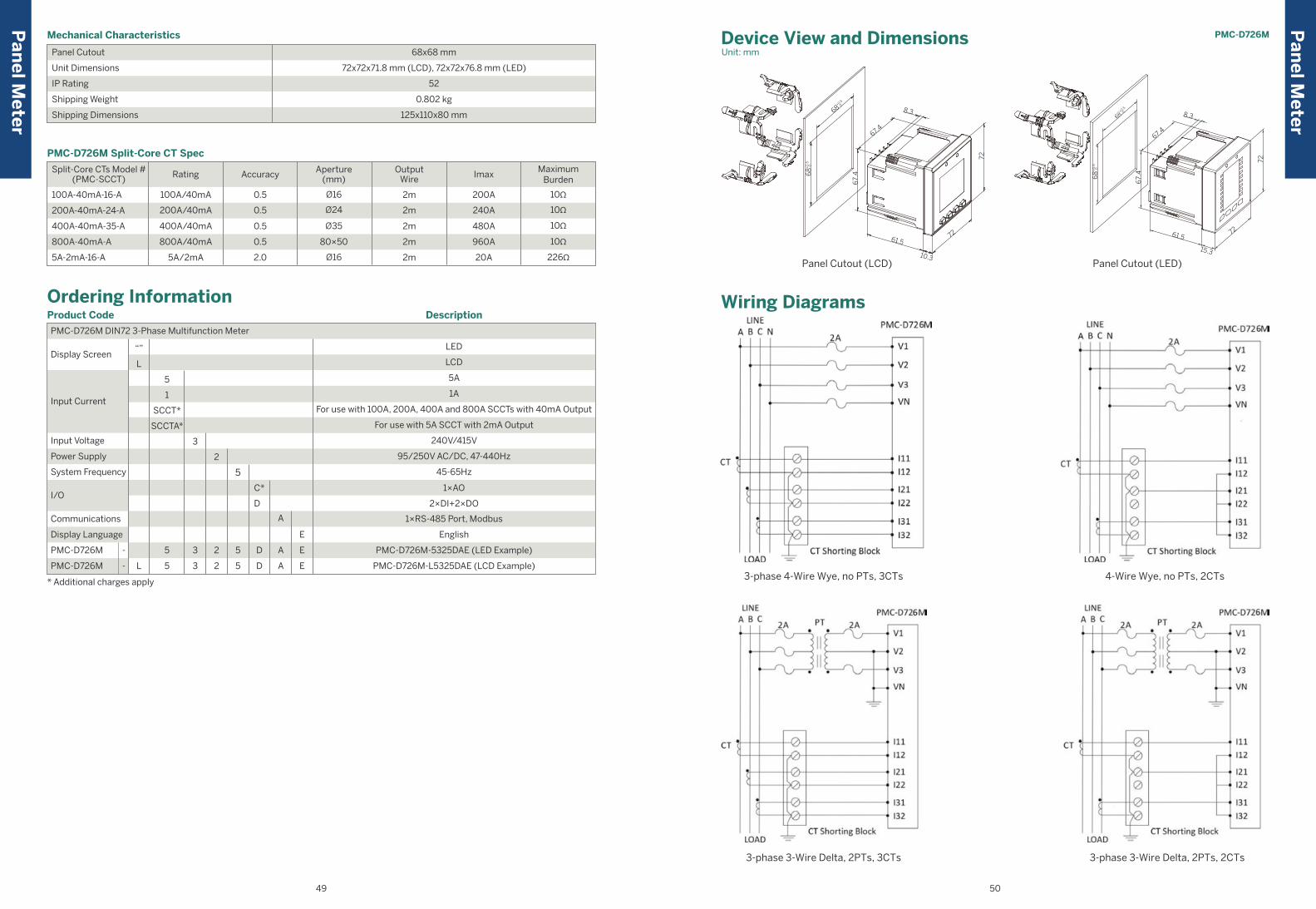
PMC-D726M
Wiring Diagrams
3-phase 4-Wire Wye, no PTs, 3CTs 4-Wire Wye, no PTs, 2CTs
3-phase 3-Wire Delta, 2PTs, 3CTs 3-phase 3-Wire Delta, 2PTs, 2CTs
PMC-D726M Split-Core CT Spec
100A-40mA-16-A
200A-40mA-24-A
400A-40mA-35-A
800A-40mA-A
5A-2mA-16-A
10Ω
10Ω
10Ω
10Ω
226Ω
Split-Core CTs Model #(PMC-SCCT)
100A/40mA
200A/40mA
400A/40mA
800A/40mA
5A/2mA
Rating
Ø16
Ø35
80×50
Ø16
Ø24
Aperture(mm)
2m
2m
2m
2m
2m
OutputWire
200A
240A
480A
960A
20A
Imax
0.5
0.5
0.5
0.5
2.0
AccuracyMaximum
Burden
* Additional charges apply
Ordering Information
Input Current
I/O
System Frequency
Power Supply
Input Voltage
Display Language
Display Screen
PMC-D726M DIN72 3-Phase Multifunction Meter
L
5-
- 5
3
3
2
2
5
5
Product Code Description
English
PMC-D726M-5325DAE (LED Example)
PMC-D726M-L5325DAE (LCD Example)
1×RS-485 Port, Modbus
LED
5A
1A
For use with 100A, 200A, 400A and 800A SCCTs with 40mA Output
For use with 5A SCCT with 2mA Output
95/250V AC/DC, 47-440Hz
45-65Hz
240V/415V
1×AO
2×DI+2×DO
LCD
PMC-D726M
PMC-D726M
5
1
SCCT*
SCCTA*
3
2
5
D
D
C*
D
A
A
A
E
E
E
“”
L
Panel Cutout
Unit Dimensions
IP Rating
Shipping Weight
Shipping Dimensions
Mechanical Characteristics
68x68 mm
72x72x71.8 mm (LCD), 72x72x76.8 mm (LED)
52
0.802 kg
125x110x80 mm
Device View and DimensionsUnit: mm
Panel Cutout (LED)Panel Cutout (LCD)10.3
61.572
72
67.4
67.
4
8.368+0.5
0
68+
0.5
0
Pan
el Meter
Pan
el Meter
49 50
72
7261.5
15.3
68
+0
.50
67.
4
67.4
8.30+0.5
68
Communications
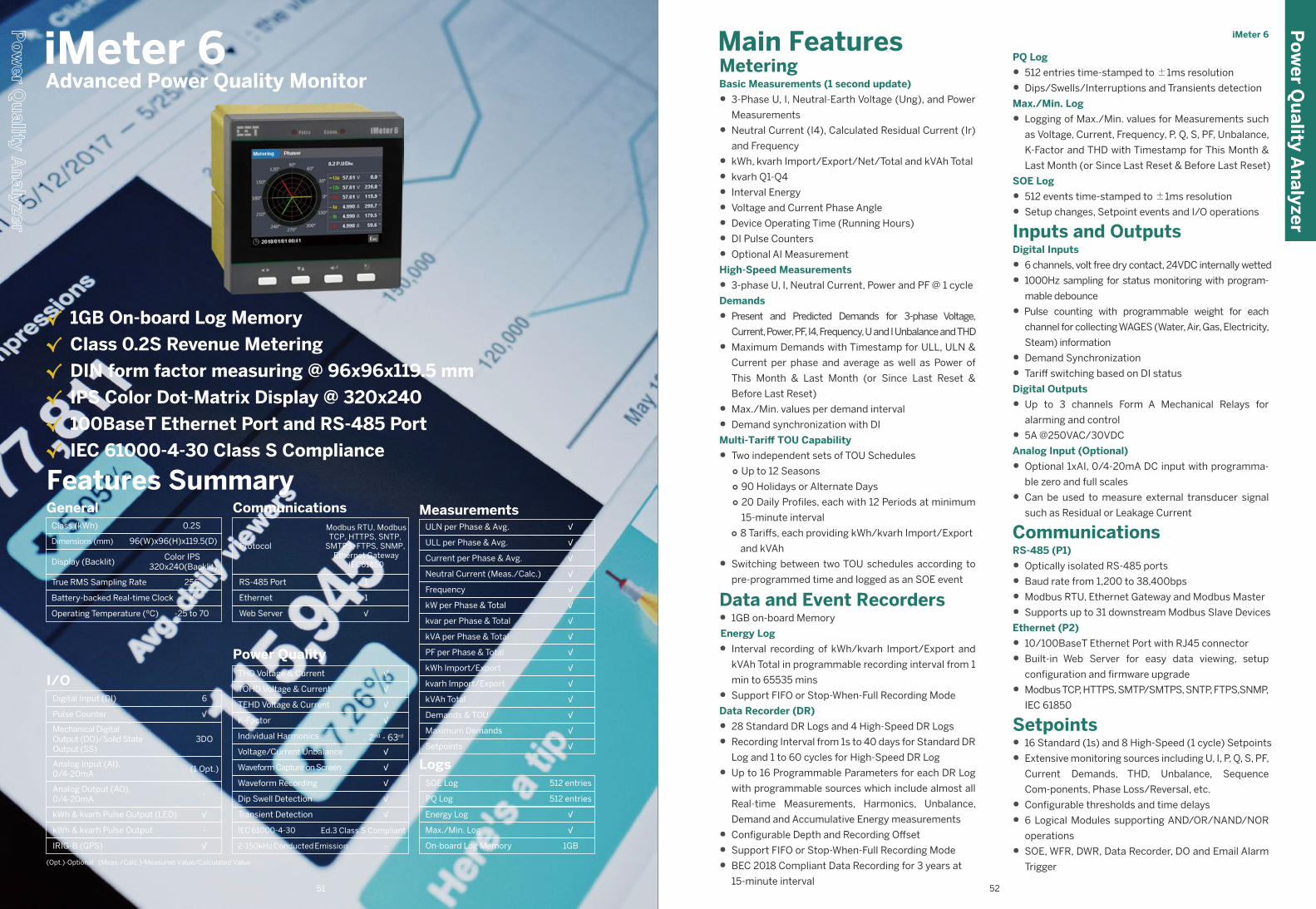
iMeter 6
MeteringBasic Measurements (1 second update)
• 3-Phase U, I, Neutral-Earth Voltage (Ung), and Power
Measurements
• Neutral Current (I4), Calculated Residual Current (Ir)
and Frequency
• kWh, kvarh Import/Export/Net/Total and kVAh Total
• kvarh Q1-Q4
• Interval Energy
• Voltage and Current Phase Angle
• Device Operating Time (Running Hours)
• DI Pulse Counters
• Optional AI Measurement
High-Speed Measurements
• 3-phase U, I, Neutral Current, Power and PF @ 1 cycle
Demands
• Present and Predicted Demands for 3-phase Voltage,
Current, Power, PF, I4, Frequency, U and I Unbalance and THD
• Maximum Demands with Timestamp for ULL, ULN &
Current per phase and average as well as Power of
This Month & Last Month (or Since Last Reset &
Before Last Reset)
• Max./Min. values per demand interval
• Demand synchronization with DI
Multi-Tariff TOU Capability
• Two independent sets of TOU Schedules ○ Up to 12 Seasons ○ 90 Holidays or Alternate Days○ 20 Daily Profiles, each with 12 Periods at minimum
15-minute interval○ 8 Tariffs, each providing kWh/kvarh Import/Export
and kVAh
• Switching between two TOU schedules according to
pre-programmed time and logged as an SOE event
Data and Event Recorders• 1GB on-board Memory
Energy Log
• Interval recording of kWh/kvarh Import/Export and
kVAh Total in programmable recording interval from 1
min to 65535 mins
• Support FIFO or Stop-When-Full Recording Mode
Data Recorder (DR)
• 28 Standard DR Logs and 4 High-Speed DR Logs
• Recording Interval from 1s to 40 days for Standard DR
Log and 1 to 60 cycles for High-Speed DR Log
• Up to 16 Programmable Parameters for each DR Log
with programmable sources which include almost all
Real-time Measurements, Harmonics, Unbalance,
Demand and Accumulative Energy measurements
• Configurable Depth and Recording Offset
• Support FIFO or Stop-When-Full Recording Mode
• BEC 2018 Compliant Data Recording for 3 years at
15-minute interval
PQ Log
• 512 entries time-stamped to ±1ms resolution
• Dips/Swells/Interruptions and Transients detection
Max./Min. Log
• Logging of Max./Min. values for Measurements such
as Voltage, Current, Frequency, P, Q, S, PF, Unbalance,
K-Factor and THD with Timestamp for This Month &
Last Month (or Since Last Reset & Before Last Reset)
SOE Log
• 512 events time-stamped to ±1ms resolution
• Setup changes, Setpoint events and I/O operations
Inputs and OutputsDigital Inputs
• 6 channels, volt free dry contact, 24VDC internally wetted
• 1000Hz sampling for status monitoring with program-
mable debounce
• Pulse counting with programmable weight for each
channel for collecting WAGES (Water, Air, Gas, Electricity,
Steam) information
• Demand Synchronization
• Tariff switching based on DI status
Digital Outputs
• Up to 3 channels Form A Mechanical Relays for
alarming and control
• 5A @250VAC/30VDC
Analog Input (Optional)
• Optional 1xAI, 0/4-20mA DC input with programma-
ble zero and full scales
• Can be used to measure external transducer signal
such as Residual or Leakage Current
CommunicationsRS-485 (P1)
• Optically isolated RS-485 ports
• Baud rate from 1,200 to 38,400bps
• Modbus RTU, Ethernet Gateway and Modbus Master
• Supports up to 31 downstream Modbus Slave Devices
Ethernet (P2)
• 10/100BaseT Ethernet Port with RJ45 connector
• Built-in Web Server for easy data viewing, setup
configuration and firmware upgrade
• Modbus TCP, HTTPS, SMTP/SMTPS, SNTP, FTPS,SNMP,
IEC 61850
Setpoints• 16 Standard (1s) and 8 High-Speed (1 cycle) Setpoints
• Extensive monitoring sources including U, I, P, Q, S, PF,
Current Demands, THD, Unbalance, Sequence
Com-ponents, Phase Loss/Reversal, etc.
• Configurable thresholds and time delays
• 6 Logical Modules supporting AND/OR/NAND/NOR
operations
• SOE, WFR, DWR, Data Recorder, DO and Email Alarm
Trigger
Main FeaturesiMeter 6 Advanced Power Quality Monitor
√ 1GB On-board Log Memory
√ Class 0.2S Revenue Metering
√ DIN form factor measuring @ 96x96x119.5 mm
√ IPS Color Dot-Matrix Display @ 320x240
√ 100BaseT Ethernet Port and RS-485 Port
√ IEC 61000-4-30 Class S Compliance
Features Summary
Class (kWh)
Operating Temperature (ºC)
Dimensions (mm)
Display (Backlit)
True RMS Sampling Rate
Battery-backed Real-time Clock
General0.2S
-25 to 70
Color IPS 320x240(Backlit)
√
96(W)x96(H)x119.5(D)
256
6
3DO
-
-
(1 Opt.)
√
√
√
I/ODigital Input (DI)
Pulse Counter
Mechanical DigitalOutput (DO)/Solid StateOutput (SS)
Analog Input (AI),0/4-20mA
Analog Output (AO),0/4-20mA
kWh & kvarh Pulse Output (LED)
kWh & kvarh Pulse Output
IRIG-B (GPS)
Communications
Protocol
RS-485 Port
Ethernet
Modbus RTU, ModbusTCP, HTTPS, SNTP,
SMTPS, FTPS, SNMP, Ethernet Gateway
IEC61850
1
1
Web Server √
Power QualityTHD Voltage & Current
TOHD Voltage & Current
TEHD Voltage & Current
K-Factor
Individual Harmonics
Voltage/Current Unbalance
Waveform Capture on Screen
Waveform Recording
Dip Swell Detection
Transient Detection
√
√
2nd - 63rd
√
√
√
√
√
√
√
IEC 61000-4-30
2-150kHz Conducted Emission
Ed.3 Class S Compliant
-
MeasurementsULN per Phase & Avg.
ULL per Phase & Avg.
Current per Phase & Avg.
Neutral Current (Meas./Calc.)
Frequency
kW per Phase & Total
kvar per Phase & Total
kVA per Phase & Total
PF per Phase & Total
kWh Import/Export
kvarh Import/Export
kVAh Total
Demands & TOU
Maximum Demands
Setpoints
√
√
√
√
√
√
√
√
√
√
√
√
√
√
√
LogsSOE Log
PQ Log
Energy Log
Max./Min. Log
On-board Log Memory
512 entries
√
1GB
512 entries
√
(Opt.)-Optional (Meas./Calc.)-Measured Value/Calculated Value
Po
wer Q
uality A
nalyzer
5251
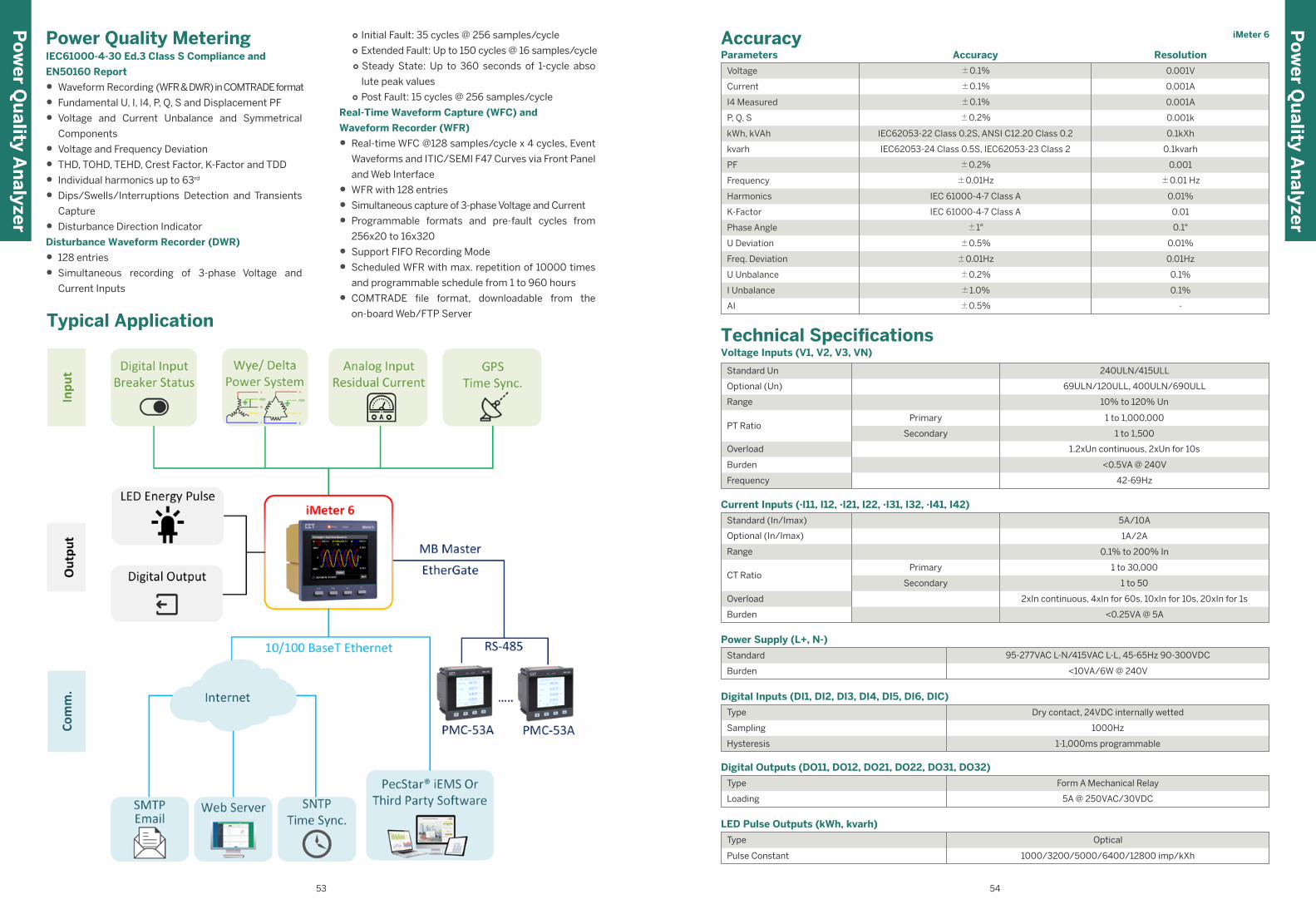
iMeter 6
Range
Optional (Un)
PT Ratio
Standard Un
10% to 120% Un
69ULN/120ULL, 400ULN/690ULL
1 to 1,000,000
1 to 1,500
Primary
Secondary
Overload
Burden
Frequency
1.2xUn continuous, 2xUn for 10s
<0.5VA @ 240V
42-69Hz
240ULN/415ULL
Voltage Inputs (V1, V2, V3, VN)
Technical Specifications
Power Supply (L+, N-)
Burden
Standard
<10VA/6W @ 240V
95-277VAC L-N/415VAC L-L, 45-65Hz 90-300VDC
Digital Inputs (DI1, DI2, DI3, DI4, DI5, DI6, DIC)
Sampling
Hysteresis
Type
1000Hz
1-1,000ms programmable
Dry contact, 24VDC internally wetted
Digital Outputs (DO11, DO12, DO21, DO22, DO31, DO32)
Type
Loading
Form A Mechanical Relay
5A @ 250VAC/30VDC
LED Pulse Outputs (kWh, kvarh)
Type
Pulse Constant
Optical
1000/3200/5000/6400/12800 imp/kXh
Parameters Accuracy Resolution
Voltage
Current
I4 Measured
P, Q, S
kWh, kVAh
±0.1%
±0.1%
±0.1%
±0.2%
IEC62053-22 Class 0.2S, ANSI C12.20 Class 0.2
0.001A
0.001V
0.001A
0.001k
0.1kXh
PF
Frequency
Harmonics
K-Factor
Phase Angle
U Deviation
Freq. Deviation
U Unbalance
I Unbalance
±0.5%
±0.01Hz
±0.2%
±1.0%
0.01%
0.01Hz
0.1%
0.1%
AI
±0.2%
±0.01Hz
IEC 61000-4-7 Class A
IEC 61000-4-7 Class A
±1°
±0.5%
0.001
±0.01 Hz
0.01%
0.01
0.1°
-
Accuracy ○ Initial Fault: 35 cycles @ 256 samples/cycle ○ Extended Fault: Up to 150 cycles @ 16 samples/cycle ○ Steady State: Up to 360 seconds of 1-cycle abso
lute peak values ○ Post Fault: 15 cycles @ 256 samples/cycle
Real-Time Waveform Capture (WFC) and
Waveform Recorder (WFR)
• Real-time WFC @128 samples/cycle x 4 cycles, Event
Waveforms and ITIC/SEMI F47 Curves via Front Panel
and Web Interface
• WFR with 128 entries
• Simultaneous capture of 3-phase Voltage and Current
• Programmable formats and pre-fault cycles from
256x20 to 16x320
• Support FIFO Recording Mode
• Scheduled WFR with max. repetition of 10000 times
and programmable schedule from 1 to 960 hours
• COMTRADE file format, downloadable from the
on-board Web/FTP Server
Power Quality MeteringIEC61000-4-30 Ed.3 Class S Compliance and
EN50160 Report
• Waveform Recording (WFR & DWR) in COMTRADE format
• Fundamental U, I, I4, P, Q, S and Displacement PF
• Voltage and Current Unbalance and Symmetrical
Components
• Voltage and Frequency Deviation
• THD, TOHD, TEHD, Crest Factor, K-Factor and TDD
• Individual harmonics up to 63rd
• Dips/Swells/Interruptions Detection and Transients
Capture
• Disturbance Direction Indicator
Disturbance Waveform Recorder (DWR)
• 128 entries
• Simultaneous recording of 3-phase Voltage and
Current Inputs
Typical Application
Po
wer Q
uality A
nalyzer
Po
wer Q
uality A
nalyzer
53 54
kvarh IEC62053-24 Class 0.5S, IEC62053-23 Class 2 0.1kvarh
Current Inputs (·I11, I12, ·I21, I22, ·I31, I32, ·I41, I42)
Standard (In/Imax)
Optional (In/Imax)
Burden
Overload
CT Ratio
Range
5A/10A
1A/2A
<0.25VA @ 5A
2xIn continuous, 4xIn for 60s, 10xIn for 10s, 20xIn for 1s
1 to 30,000
1 to 50
0.1% to 200% In
Primary
Secondary
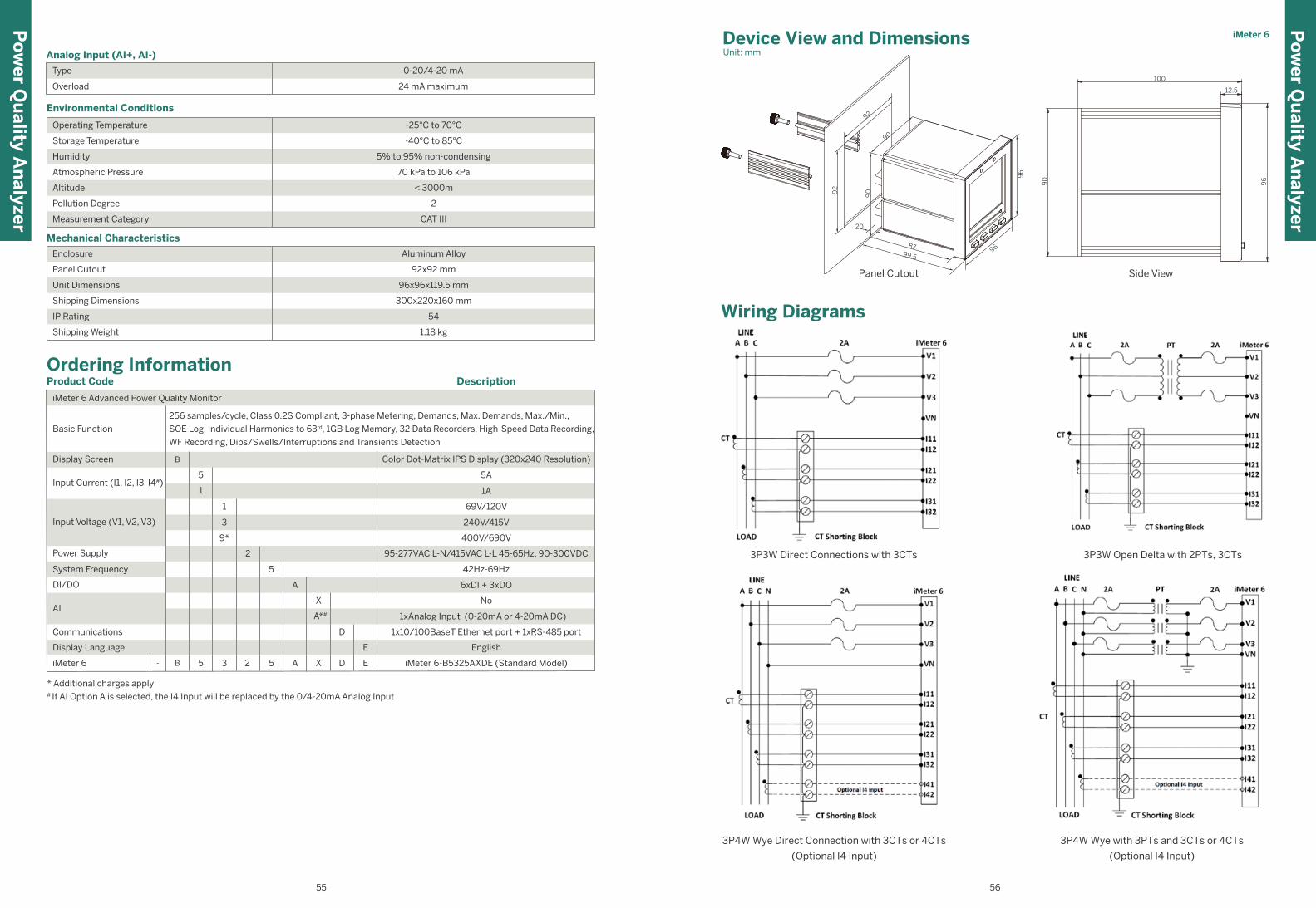
Po
wer Q
uality A
nalyzer
iMeter 6
Wiring Diagrams
3P4W Wye Direct Connection with 3CTs or 4CTs
(Optional I4 Input)
3P3W Direct Connections with 3CTs 3P3W Open Delta with 2PTs, 3CTs
3P4W Wye with 3PTs and 3CTs or 4CTs
(Optional I4 Input)
Side View
Device View and Dimensions Unit: mm
96
Panel Cutout
8799.5
20
92
90
90
92
96
12.5
100
90
96
Ordering InformationProduct Code
iMeter 6 Advanced Power Quality Monitor
256 samples/cycle, Class 0.2S Compliant, 3-phase Metering, Demands, Max. Demands, Max./Min.,
SOE Log, Individual Harmonics to 63rd, 1GB Log Memory, 32 Data Recorders, High-Speed Data Recording,
WF Recording, Dips/Swells/Interruptions and Transients Detection
Basic Function
Power Supply
System Frequency
DI/DO
Communications
Display Language
iMeter 6
95-277VAC L-N/415VAC L-L 45-65Hz, 90-300VDC
B- 5 5 A X D E3 2
69V/120V
240V/415V
400V/690V
42Hz-69Hz
6xDI + 3xDO
No
1xAnalog Input (0-20mA or 4-20mA DC)
English
1x10/100BaseT Ethernet port + 1xRS-485 port
iMeter 6-B5325AXDE (Standard Model)
Color Dot-Matrix IPS Display (320x240 Resolution)Display Screen
Input Current (I1, I2, I3, I4#)
Input Voltage (V1, V2, V3)
Description
* Additional charges apply# If AI Option A is selected, the I4 Input will be replaced by the 0/4-20mA Analog Input
AI
5A
1A
B
5
A
X
D
E
A*#
3
1
2
9*
5
1
Environmental Conditions
Operating Temperature
Storage Temperature
Measurement Category
Pollution Degree
Altitude
Atmospheric Pressure
Humidity
-25°C to 70°C
-40°C to 85°C
CAT III
2
70 kPa to 106 kPa
< 3000m
5% to 95% non-condensing
Mechanical Characteristics
Enclosure
Panel Cutout
Shipping Weight
IP Rating
Shipping Dimensions
Unit Dimensions
Aluminum Alloy
92x92 mm
1.18 kg
300x220x160 mm
54
96x96x119.5 mm
Po
wer Q
uality A
nalyzer
55 56
Analog Input (AI+, AI-)
Overload 24 mA maximum
Type 0-20/4-20 mA
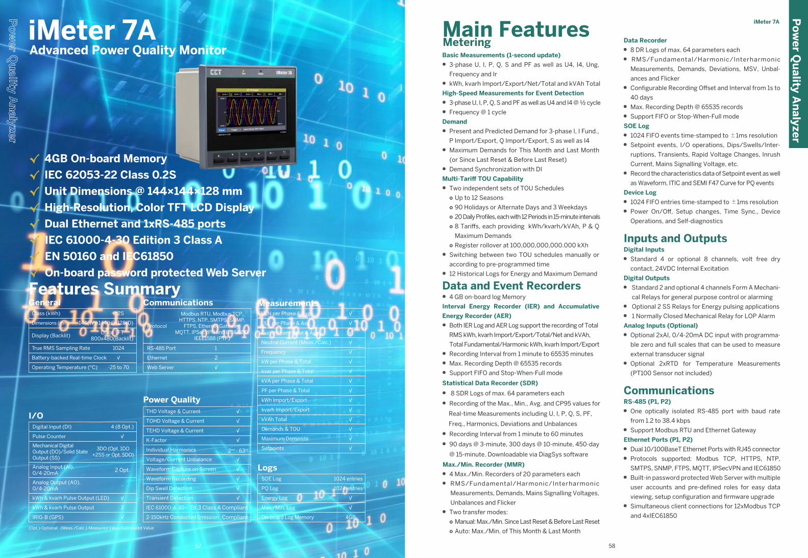
iMeter 7A
Data Recorder
• 8 DR Logs of max. 64 parameters each
• RMS/Fundamental/Harmonic/Interharmonic
Measurements, Demands, Deviations, MSV, Unbal-
ances and Flicker
• Configurable Recording Offset and Interval from 1s to
40 days
• Max. Recording Depth @ 65535 records
• Support FIFO or Stop-When-Full mode
SOE Log
• 1024 FIFO events time-stamped to ±1ms resolution
• Setpoint events, I/O operations, Dips/Swells/Inter-
ruptions, Transients, Rapid Voltage Changes, Inrush
Current, Mains Signalling Voltage, etc.
• Record the characteristics data of Setpoint event as well
as Waveform, ITIC and SEMI F47 Curve for PQ events
Device Log
• 1024 FIFO entries time-stamped to ±1ms resolution
• Power On/Off, Setup changes, Time Sync., Device
Operations, and Self-diagnostics
Inputs and OutputsDigital Inputs
• Standard 4 or optional 8 channels, volt free dry
contact, 24VDC Internal Excitation
Digital Outputs
• Standard 2 and optional 4 channels Form A Mechani-
cal Relays for general purpose control or alarming
• Optional 2 SS Relays for Energy pulsing applications
• 1 Normally Closed Mechanical Relay for LOP Alarm
Analog Inputs (Optional)
• Optional 2xAI, 0/4-20mA DC input with programma-
ble zero and full scales that can be used to measure
external transducer signal
• Optional 2xRTD for Temperature Measurements
(PT100 Sensor not included)
CommunicationsRS-485 (P1, P2)
• One optically isolated RS-485 port with baud rate
from 1.2 to 38.4 kbps
• Support Modbus RTU and Ethernet Gateway
Ethernet Ports (P1, P2)
• Dual 10/100BaseT Ethernet Ports with RJ45 connector
• Protocols supported: Modbus TCP, HTTPS, NTP,
SMTPS, SNMP, FTPS, MQTT, IPSecVPN and IEC61850
• Built-in password protected Web Server with multiple
user accounts and pre-defined roles for easy data
viewing, setup configuration and firmware upgrade
• Simultaneous client connections for 12xModbus TCP
and 4xIEC61850
Basic Measurements (1-second update)
• 3-phase U, I, P, Q, S and PF as well as U4, I4, Ung,
Frequency and Ir
• kWh, kvarh Import/Export/Net/Total and kVAh Total
High-Speed Measurements for Event Detection
• 3-phase U, I, P, Q, S and PF as well as U4 and I4 @ ½ cycle
• Frequency @ 1 cycle
Demand
• Present and Predicted Demand for 3-phase I, I Fund.,
P Import/Export, Q Import/Export, S as well as I4
• Maximum Demands for This Month and Last Month
(or Since Last Reset & Before Last Reset)
• Demand Synchronization with DI
Multi-Tariff TOU Capability
• Two independent sets of TOU Schedules○ Up to 12 Seasons○ 90 Holidays or Alternate Days and 3 Weekdays○ 20 Daily Profiles, each with 12 Periods in 15-minute intervals○ 8 Tariffs, each providing kWh/kvarh/kVAh, P & Q
Maximum Demands○ Register rollover at 100,000,000,000.000 kXh
• Switching between two TOU schedules manually or
according to pre-programmed time
• 12 Historical Logs for Energy and Maximum Demand
Data and Event Recorders• 4 GB on-board log Memory
Interval Energy Recorder (IER) and Accumulative
Energy Recorder (AER)
• Both IER Log and AER Log support the recording of Total
RMS kWh, kvarh Import/Export/Total/Net and kVAh,
Total Fundamental/Harmonic kWh, kvarh Import/Export
• Recording Interval from 1 minute to 65535 minutes
• Max. Recording Depth @ 65535 records
• Support FIFO and Stop-When-Full mode
Statistical Data Recorder (SDR)
• 8 SDR Logs of max. 64 parameters each
• Recording of the Max., Min., Avg. and CP95 values for
Real-time Measurements including U, I, P, Q, S, PF,
Freq., Harmonics, Deviations and Unbalances
• Recording Interval from 1 minute to 60 minutes
• 90 days @ 3-minute, 300 days @ 10-minute, 450-day
@ 15-minute. Downloadable via DiagSys software
Max./Min. Recorder (MMR)
• 4 Max./Min. Recorders of 20 parameters each
• RMS/Fundamental/Harmonic/Interharmonic
Measurements, Demands, Mains Signalling Voltages,
Unbalances and Flicker
• Two transfer modes:○ Manual: Max./Min. Since Last Reset & Before Last Reset○ Auto: Max./Min. of This Month & Last Month
√ 4GB On-board Memory
√ IEC 62053-22 Class 0.2S
√ Unit Dimensions @ 144×144×128 mm
√ High-Resolution, Color TFT LCD Display
√ Dual Ethernet and 1xRS-485 ports
√ IEC 61000-4-30 Edition 3 Class A
√ EN 50160 and IEC61850
√ On-board password protected Web Server
iMeter 7A Advanced Power Quality Monitor
Main FeaturesMetering
Po
wer Q
uality A
nalyzer
57 58
Features Summary Class (kWh)
Operating Temperature (ºC)
Dimensions (mm)
Display (Backlit)
True RMS Sampling Rate
Battery-backed Real-time Clock
General0.2S
-25 to 70
Color TFT800x480(Backlit)
√
144(W)x144(H)x128(D)
1024
4 (8 Opt.)
3DO (Opt. 1DO+2SS or Opt. 5DO)
-
2
2 Opt.
√
√
√
I/ODigital Input (DI)
Pulse Counter
Mechanical DigitalOutput (DO)/Solid StateOutput (SS)
Analog Input (AI),0/4-20mA
Analog Output (AO),0/4-20mA
kWh & kvarh Pulse Output (LED)
kWh & kvarh Pulse Output
IRIG-B (GPS)
Communications
Protocol
RS-485 Port
Ethernet
Modbus RTU, Modbus TCP,HTTPS, NTP, SMTPS, SNMP,
FTPS, Ethernet Gateway,MQTT, IPSecVPN and IEC61850,
IEEE1588 (PTP)
1
2
Web Server √
Power QualityTHD Voltage & Current
TOHD Voltage & Current
TEHD Voltage & Current
K-Factor
Individual Harmonics
Voltage/Current Unbalance
Waveform Capture on Screen
Waveform Recording
Dip Swell Detection
Transient Detection
√
√
2nd - 63rd
√
√
√
√
√
√
√
IEC 61000-4-30
2-150kHz Conducted Emission
Ed.3 Class A Compliant
Compliant
MeasurementsULN per Phase & Avg.
ULL per Phase & Avg.
Current per Phase & Avg.
Neutral Current (Meas./Calc.)
Frequency
kW per Phase & Total
kvar per Phase & Total
kVA per Phase & Total
PF per Phase & Total
kWh Import/Export
kvarh Import/Export
kVAh Total
Demands & TOU
Maximum Demands
Setpoints
√
√
√
√
√
√
√
√
√
√
√
√
√
√
√
LogsSOE Log
PQ Log
Energy Log
Max./Min. Log
On-board Log Memory
1024 entries
√
4GB
1024 entries
√
(Opt.)-Optional (Meas./Calc.)-Measured Value/Calculated Value
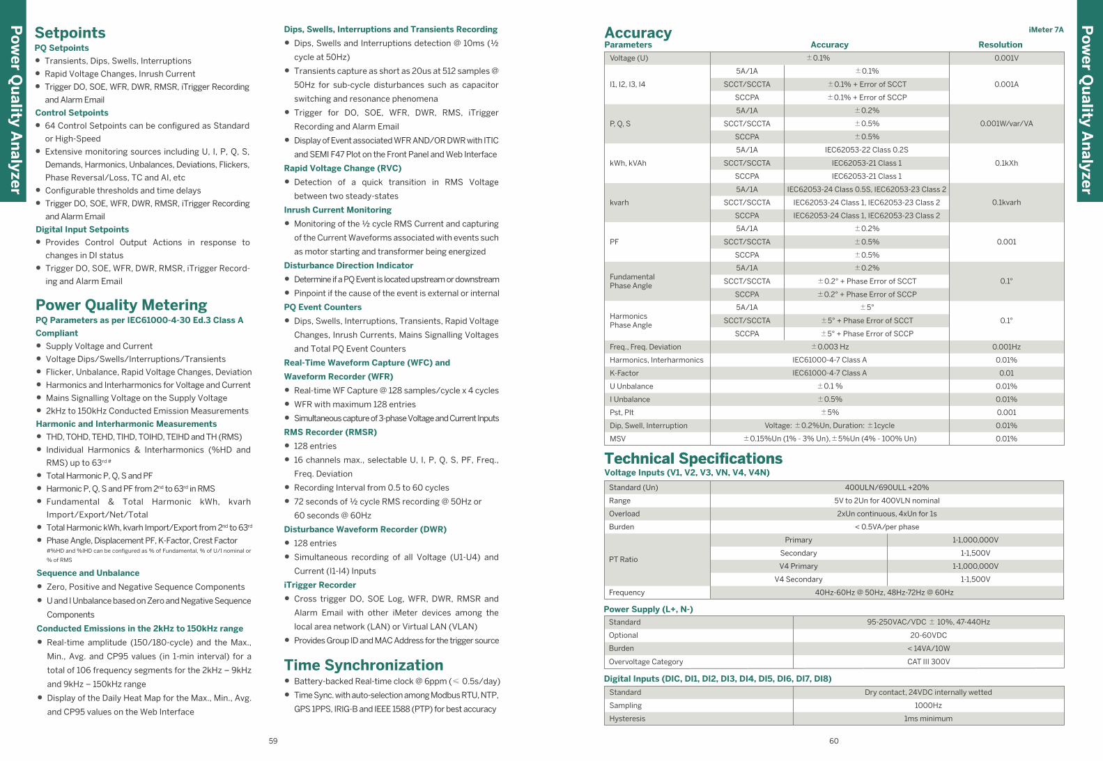
iMeter 7A
Po
wer Q
uality A
nalyzer
Po
wer Q
uality A
nalyzer
SetpointsPQ Setpoints
• Transients, Dips, Swells, Interruptions
• Rapid Voltage Changes, Inrush Current
• Trigger DO, SOE, WFR, DWR, RMSR, iTrigger Recording
and Alarm Email
Control Setpoints
• 64 Control Setpoints can be configured as Standard
or High-Speed
• Extensive monitoring sources including U, I, P, Q, S,
Demands, Harmonics, Unbalances, Deviations, Flickers,
Phase Reversal/Loss, TC and AI, etc
• Configurable thresholds and time delays
• Trigger DO, SOE, WFR, DWR, RMSR, iTrigger Recording
and Alarm Email
Digital Input Setpoints
• Provides Control Output Actions in response to
changes in DI status
• Trigger DO, SOE, WFR, DWR, RMSR, iTrigger Record-
ing and Alarm Email
Power Quality MeteringPQ Parameters as per IEC61000-4-30 Ed.3 Class A
Compliant
• Supply Voltage and Current
• Voltage Dips/Swells/Interruptions/Transients
• Flicker, Unbalance, Rapid Voltage Changes, Deviation
• Harmonics and Interharmonics for Voltage and Current
• Mains Signalling Voltage on the Supply Voltage
• 2kHz to 150kHz Conducted Emission Measurements
Harmonic and Interharmonic Measurements
• THD, TOHD, TEHD, TIHD, TOIHD, TEIHD and TH (RMS)
• Individual Harmonics & Interharmonics (%HD and
RMS) up to 63rd #
• Total Harmonic P, Q, S and PF
• Harmonic P, Q, S and PF from 2nd to 63rd in RMS
• Fundamental & Total Harmonic kWh, kvarh
Import/Export/Net/Total
• Total Harmonic kWh, kvarh Import/Export from 2nd to 63rd
• Phase Angle, Displacement PF, K-Factor, Crest Factor#%HD and %IHD can be configured as % of Fundamental, % of U/I nominal or
% of RMS
Sequence and Unbalance
• Zero, Positive and Negative Sequence Components
• U and I Unbalance based on Zero and Negative Sequence
Components
Conducted Emissions in the 2kHz to 150kHz range
• Real-time amplitude (150/180-cycle) and the Max.,
Min., Avg. and CP95 values (in 1-min interval) for a
total of 106 frequency segments for the 2kHz – 9kHz
and 9kHz – 150kHz range
• Display of the Daily Heat Map for the Max., Min., Avg.
and CP95 values on the Web Interface
Dips, Swells, Interruptions and Transients Recording
• Dips, Swells and Interruptions detection @ 10ms (½
cycle at 50Hz)
• Transients capture as short as 20us at 512 samples @
50Hz for sub-cycle disturbances such as capacitor
switching and resonance phenomena
• Trigger for DO, SOE, WFR, DWR, RMS, iTrigger
Recording and Alarm Email
• Display of Event associated WFR AND/OR DWR with ITIC
and SEMI F47 Plot on the Front Panel and Web Interface
Rapid Voltage Change (RVC)
• Detection of a quick transition in RMS Voltage
between two steady-states
Inrush Current Monitoring
• Monitoring of the ½ cycle RMS Current and capturing
of the Current Waveforms associated with events such
as motor starting and transformer being energized
Disturbance Direction Indicator
• Determine if a PQ Event is located upstream or downstream
• Pinpoint if the cause of the event is external or internal
PQ Event Counters
• Dips, Swells, Interruptions, Transients, Rapid Voltage
Changes, Inrush Currents, Mains Signalling Voltages
and Total PQ Event Counters
Real-Time Waveform Capture (WFC) and
Waveform Recorder (WFR)
• Real-time WF Capture @ 128 samples/cycle x 4 cycles
• WFR with maximum 128 entries
• Simultaneous capture of 3-phase Voltage and Current Inputs
RMS Recorder (RMSR)
• 128 entries
• 16 channels max., selectable U, I, P, Q, S, PF, Freq.,
Freq. Deviation
• Recording Interval from 0.5 to 60 cycles
• 72 seconds of ½ cycle RMS recording @ 50Hz or
60 seconds @ 60Hz
Disturbance Waveform Recorder (DWR)
• 128 entries
• Simultaneous recording of all Voltage (U1-U4) and
Current (I1-I4) Inputs
iTrigger Recorder
• Cross trigger DO, SOE Log, WFR, DWR, RMSR and
Alarm Email with other iMeter devices among the
local area network (LAN) or Virtual LAN (VLAN)
• Provides Group ID and MAC Address for the trigger source
Time Synchronization• Battery-backed Real-time clock @ 6ppm (≤ 0.5s/day)
• Time Sync. with auto-selection among Modbus RTU, NTP,
GPS 1PPS, IRIG-B and IEEE 1588 (PTP) for best accuracy
59 60
Voltage Inputs (V1, V2, V3, VN, V4, V4N)
Overload
Frequency
Primary
V4 Primary
Secondary
Technical SpecificationsTechnical Specifications
PT Ratio
Burden
Standard (Un)
Range
V4 Secondary
2xUn continuous, 4xUn for 1s
< 0.5VA/per phase
400ULN/690ULL +20%
5V to 2Un for 400VLN nominal
1-1,000,000V
1-1,000,000V
1-1,500V
1-1,500V
40Hz-60Hz @ 50Hz, 48Hz-72Hz @ 60Hz
Parameters Accuracy Resolution
Voltage (U)
I1, I2, I3, I4
P, Q, S
kvarh
±0.1%
5A/1A
SCCT/SCCTA
SCCPA
5A/1A
SCCT/SCCTA
SCCPA
±0.1%
±0.1% + Error of SCCT
±0.1% + Error of SCCP
kWh, kVAh
5A/1A
SCCT/SCCTA
SCCPA
IEC62053-22 Class 0.2S
IEC62053-21 Class 1
5A/1A IEC62053-24 Class 0.5S, IEC62053-23 Class 2
SCCPA IEC62053-24 Class 1, IEC62053-23 Class 2
IEC62053-21 Class 1
PF
5A/1A
SCCPA
±0.2%
±0.5%
±0.5%
SCCT/SCCTA
SCCT/SCCTA
IEC62053-24 Class 1, IEC62053-23 Class 2
±0.2%
±0.5%
±0.5%
0.001V
Freq., Freq. Deviation ±0.003 Hz 0.001Hz
Harmonics, Interharmonics IEC61000-4-7 Class A 0.01%
K-Factor IEC61000-4-7 Class A 0.01
U Unbalance ±0.1 % 0.01%
I Unbalance ±0.5% 0.01%
Dip, Swell, Interruption Voltage: ±0.2%Un, Duration: ±1cycle
±0.15%Un (1% - 3% Un),±5%Un (4% - 100% Un)
0.01%
0.01%
Pst, Plt
MSV
±5% 0.001
0.001A
0.1kXh
FundamentalPhase Angle
5A/1A
SCCT/SCCTA
SCCPA
±0.2%
HarmonicsPhase Angle
5A/1A
SCCPA
±5°
±5° + Phase Error of SCCT
±5° + Phase Error of SCCP
SCCT/SCCTA
±0.2° + Phase Error of SCCT
±0.2° + Phase Error of SCCP
0.1kXh
0.001
0.1°
0.001W/var/VA
0.1kvarh
0.1°
Accuracy
Sampling
Standard
Hysteresis
Digital Inputs (DIC, DI1, DI2, DI3, DI4, DI5, DI6, DI7, DI8)
Dry contact, 24VDC internally wetted
1000Hz
1ms minimum
Power Supply (L+, N-)
Standard
Optional
Burden
Overvoltage Category
95-250VAC/VDC ± 10%, 47-440Hz
20-60VDC
< 14VA/10W
CAT III 300V
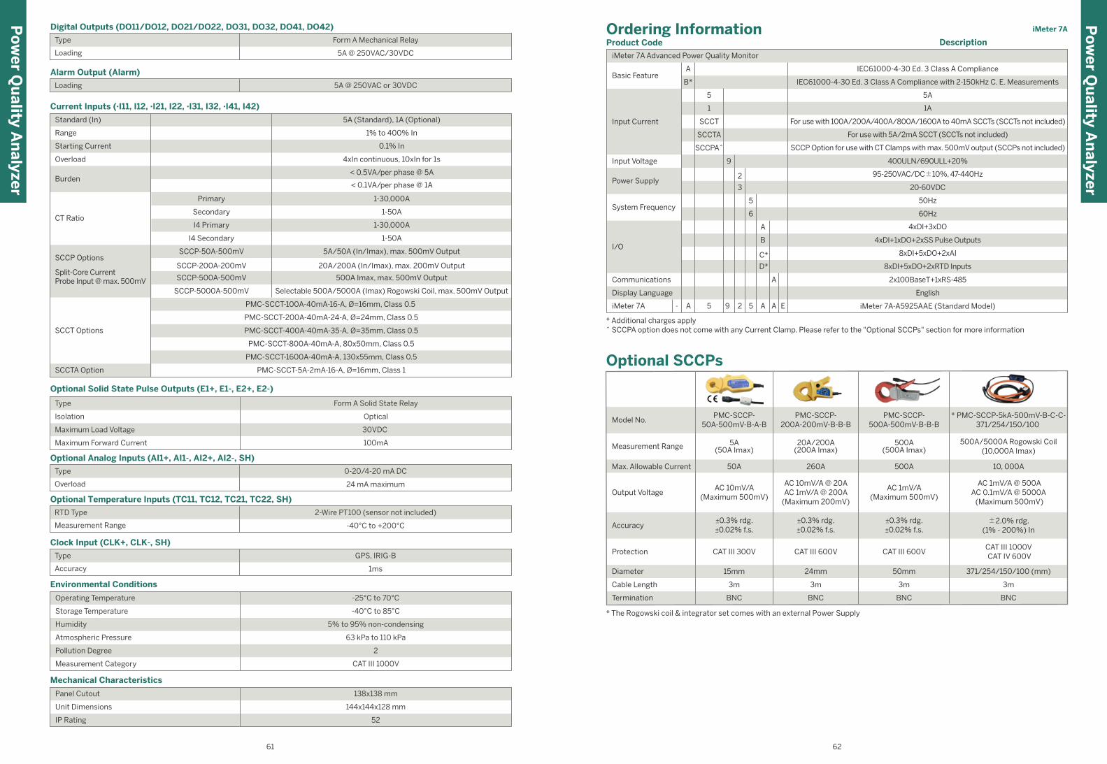
iMeter 7A
61 62
Po
wer Q
uality A
nalyzer
Po
wer Q
uality A
nalyzer
56
Digital Outputs (DO11/DO12, DO21/DO22, DO31, DO32, DO41, DO42)
Type
Loading
Form A Mechanical Relay
5A @ 250VAC/30VDC
Alarm Output (Alarm)
Loading 5A @ 250VAC or 30VDC
Current Inputs (·I11, I12, ·I21, I22, ·I31, I32, ·I41, I42)
Overload
CT Ratio
SCCP Options
Split-Core CurrentProbe Input @ max. 500mV
Burden
Standard (In)
Range
Starting Current
Primary
I4 Primary
Secondary
I4 Secondary
SCCP-50A-500mV
SCCP-200A-200mV
SCCP-5000A-500mV
SCCP-500A-500mV
< 0.5VA/per phase @ 5A
4xIn continuous, 10xIn for 1s
< 0.1VA/per phase @ 1A
1% to 400% In
5A (Standard), 1A (Optional)
0.1% In
1-30,000A
1-30,000A
1-50A
1-50A
5A/50A (In/Imax), max. 500mV Output
20A/200A (In/Imax), max. 200mV Output
500A Imax, max. 500mV Output
Selectable 500A/5000A (Imax) Rogowski Coil, max. 500mV Output
PMC-SCCT-100A-40mA-16-A, Ø=16mm, Class 0.5
PMC-SCCT-200A-40mA-24-A, Ø=24mm, Class 0.5
PMC-SCCT-400A-40mA-35-A, Ø=35mm, Class 0.5
PMC-SCCT-800A-40mA-A, 80x50mm, Class 0.5
PMC-SCCT-1600A-40mA-A, 130x55mm, Class 0.5
PMC-SCCT-5A-2mA-16-A, Ø=16mm, Class 1
SCCT Options
SCCTA Option
Optional Solid State Pulse Outputs (E1+, E1-, E2+, E2-)
Type
Isolation
Maximum Load Voltage
Maximum Forward Current
Form A Solid State Relay
Optical
30VDC
100mA
Optional Analog Inputs (AI1+, AI1-, AI2+, AI2-, SH)
Type
Overload
0-20/4-20 mA DC
24 mA maximum
Optional Temperature Inputs (TC11, TC12, TC21, TC22, SH)
RTD Type
Measurement Range
2-Wire PT100 (sensor not included)
-40°C to +200°C
Clock Input (CLK+, CLK-, SH)
Type
Accuracy
GPS, IRIG-B
1ms
Operating Temperature
Storage Temperature
Humidity
Atmospheric Pressure
Pollution Degree
Measurement Category
-40°C to 85°C
5% to 95% non-condensing
63 kPa to 110 kPa
Environmental Conditions
-25°C to 70°C
2
CAT III 1000V
Unit Dimensions
Panel Cutout
IP Rating
Mechanical Characteristics
138x138 mm
144x144x128 mm
52
4xDI+3xDO
4xDI+1xDO+2xSS Pulse Outputs
8xDI+5xDO+2xRTD Inputs
8xDI+5xDO+2xAI
English
2x100BaseT+1xRS-485
95-250VAC/DC±10%, 47-440Hz
20-60VDC3
2
* Additional charges apply^ SCCPA option does not come with any Current Clamp. Please refer to the "Optional SCCPs" section for more information
iMeter 7A 95A- 2 A
A
E5 A iMeter 7A-A5925AAE (Standard Model)
Ordering InformationProduct Code
iMeter 7A Advanced Power Quality Monitor
Basic Feature
Power Supply
50Hz
60Hz6
5
B
A
D*
C*
System Frequency
Communications
Display Language
I/O
A
Input Current
Input Voltage
Description
B*
5
IEC61000-4-30 Ed. 3 Class A Compliance with 2-150kHz C. E. Measurements
5A
1
SCCT
SCCTA
SCCPA^
1A
For use with 100A/200A/400A/800A/1600A to 40mA SCCTs (SCCTs not included)
SCCP Option for use with CT Clamps with max. 500mV output (SCCPs not included)
For use with 5A/2mA SCCT (SCCTs not included)
400ULN/690ULL+20%
IEC61000-4-30 Ed. 3 Class A Compliance
9
* The Rogowski coil & integrator set comes with an external Power Supply
Optional SCCPs
BNC BNC
3m 3m
BNC
3m
15mm 24mm 50mm
CAT III 600V CAT III 600VCAT III 300V
±0.3% rdg.±0.02% f.s.
±0.3% rdg.±0.02% f.s.
±0.3% rdg.±0.02% f.s.
AC 10mV/A(Maximum 500mV)
AC 10mV/A @ 20AAC 1mV/A @ 200A
(Maximum 200mV)
AC 1mV/A(Maximum 500mV)
50A 260A 500A
5A(50A Imax)
20A/200A(200A Imax)
500A(500A Imax)
PMC-SCCP-50A-500mV-B-A-B
Model No.PMC-SCCP-
200A-200mV-B-B-BPMC-SCCP-
500A-500mV-B-B-B
Measurement Range
Max. Allowable Current
Output Voltage
Accuracy
Protection
Diameter
Cable Length
Termination BNC
3m
371/254/150/100 (mm)
CAT III 1000V CAT IV 600V
±2.0% rdg.(1% - 200%) In
AC 1mV/A @ 500AAC 0.1mV/A @ 5000A (Maximum 500mV)
10, 000A
500A/5000A Rogowski Coil(10,000A Imax)
* PMC-SCCP-5kA-500mV-B-C-C-371/254/150/100
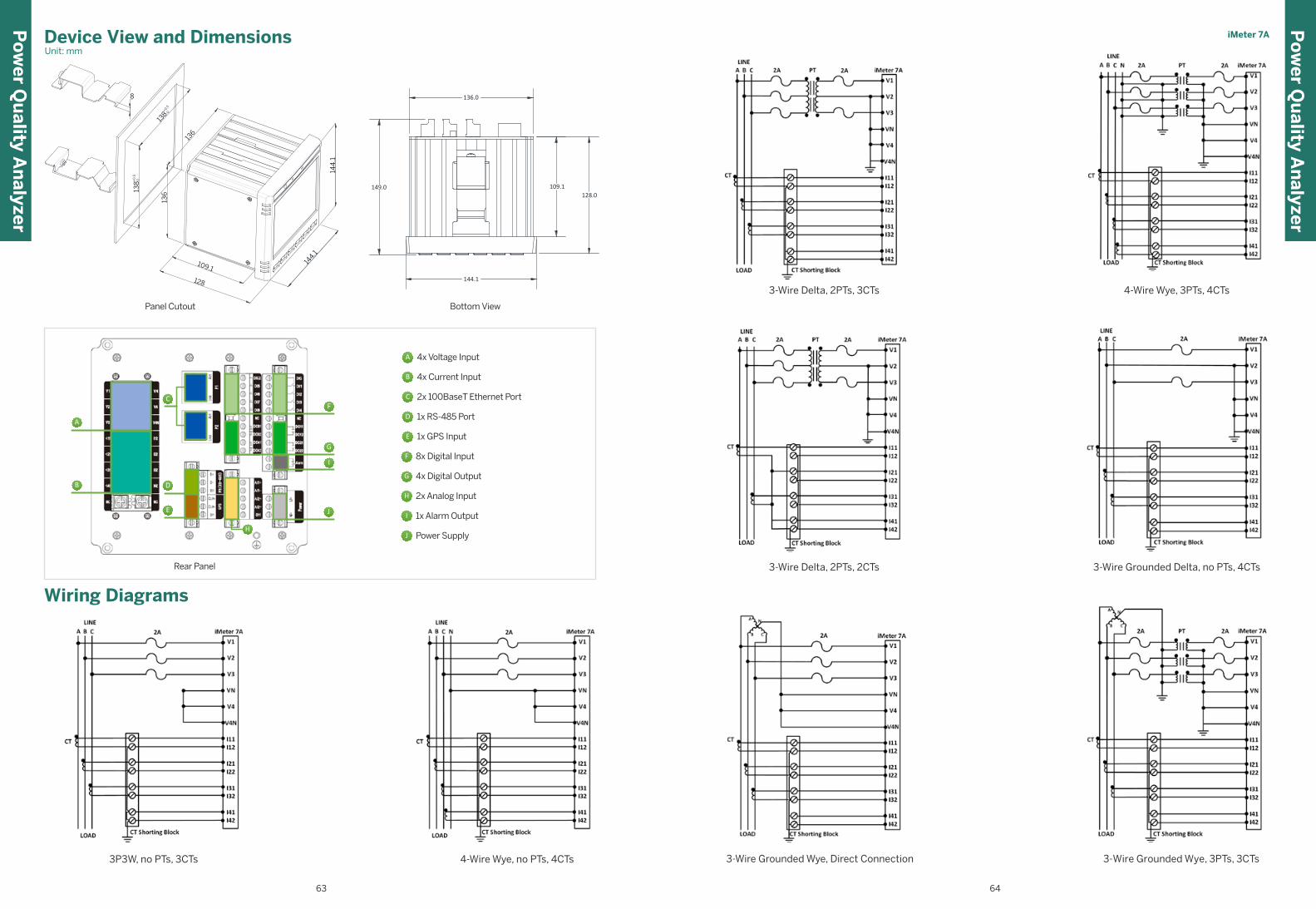
63 64
Po
wer Q
uality A
nalyzer
Wiring Diagrams
4-Wire Wye, no PTs, 4CTs3P3W, no PTs, 3CTs
Device View and DimensionsUnit: mm
Panel Cutout
109.1
128
144.1
+0.5 0
144
.1
+0
.5 0
136
136
138
8
138
A 4x Voltage Input
B 4x Current Input
C 2x 100BaseT Ethernet Port
D 1x RS-485 Port
E 1x GPS Input
F 8x Digital Input
G 4x Digital Output
H 2x Analog Input
I 1x Alarm Output
J Power Supply
A
B
C
D
I
JE
F
G
H
Rear Panel
3-Wire Grounded Wye, 3PTs, 3CTs3-Wire Grounded Wye, Direct Connection
3-Wire Delta, 2PTs, 3CTs 4-Wire Wye, 3PTs, 4CTs
3-Wire Delta, 2PTs, 2CTs 3-Wire Grounded Delta, no PTs, 4CTs
Front View
Bottom View
144.1
136.0
128.0109.1149.0
iMeter 7AP
ow
er Qu
ality An
alyzer
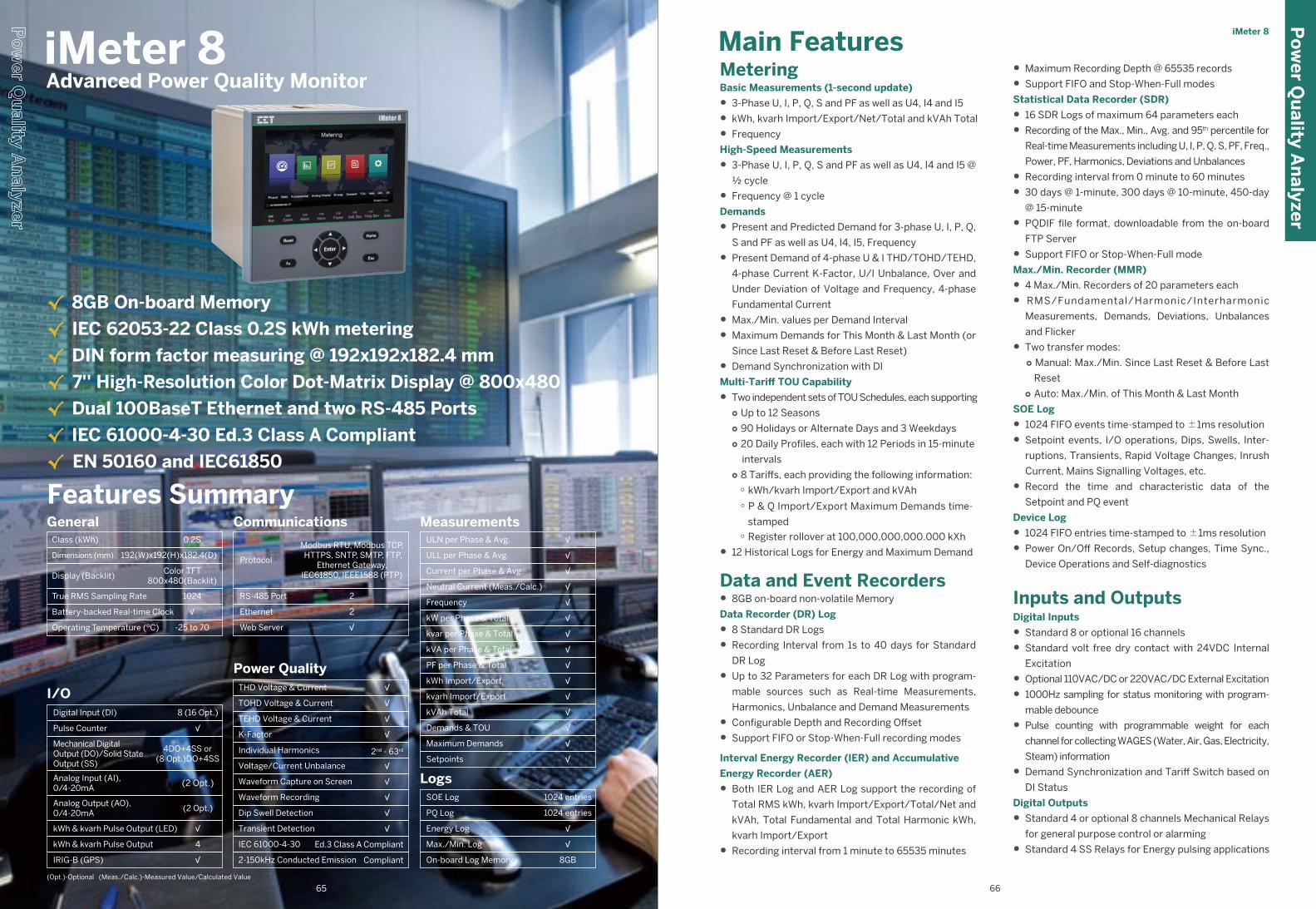
MeteringBasic Measurements (1-second update)
• 3-Phase U, I, P, Q, S and PF as well as U4, I4 and I5
• kWh, kvarh Import/Export/Net/Total and kVAh Total
• Frequency
High-Speed Measurements
• 3-Phase U, I, P, Q, S and PF as well as U4, I4 and I5 @
½ cycle
• Frequency @ 1 cycle
Demands
• Present and Predicted Demand for 3-phase U, I, P, Q,
S and PF as well as U4, I4, I5, Frequency
• Present Demand of 4-phase U & I THD/TOHD/TEHD,
4-phase Current K-Factor, U/I Unbalance, Over and
Under Deviation of Voltage and Frequency, 4-phase
Fundamental Current
• Max./Min. values per Demand Interval
• Maximum Demands for This Month & Last Month (or
Since Last Reset & Before Last Reset)
• Demand Synchronization with DI
Multi-Tariff TOU Capability
• Two independent sets of TOU Schedules, each supporting○ Up to 12 Seasons○ 90 Holidays or Alternate Days and 3 Weekdays○ 20 Daily Profiles, each with 12 Periods in 15-minute
intervals○ 8 Tariffs, each providing the following information:
○ kWh/kvarh Import/Export and kVAh
○ Register rollover at 100,000,000,000.000 kXh
• 12 Historical Logs for Energy and Maximum Demand
Data and Event Recorders• 8GB on-board non-volatile Memory
Data Recorder (DR) Log
• 8 Standard DR Logs
• Recording Interval from 1s to 40 days for Standard
DR Log
• Up to 32 Parameters for each DR Log with program-
mable sources such as Real-time Measurements,
Harmonics, Unbalance and Demand Measurements
• Configurable Depth and Recording Offset
• Support FIFO or Stop-When-Full recording modes
Interval Energy Recorder (IER) and Accumulative
Energy Recorder (AER)
• Both IER Log and AER Log support the recording of
Total RMS kWh, kvarh Import/Export/Total/Net and
kVAh, Total Fundamental and Total Harmonic kWh,
kvarh Import/Export
• Recording interval from 1 minute to 65535 minutes
• Maximum Recording Depth @ 65535 records
• Support FIFO and Stop-When-Full modes
Statistical Data Recorder (SDR)
• 16 SDR Logs of maximum 64 parameters each
• Recording of the Max., Min., Avg. and 95th percentile for
Real-time Measurements including U, I, P, Q, S, PF, Freq.,
Power, PF, Harmonics, Deviations and Unbalances
• Recording interval from 0 minute to 60 minutes
• 30 days @ 1-minute, 300 days @ 10-minute, 450-day
@ 15-minute
• PQDIF file format, downloadable from the on-board
FTP Server
• Support FIFO or Stop-When-Full mode
Max./Min. Recorder (MMR)
• 4 Max./Min. Recorders of 20 parameters each
• RMS/Fundamental/Harmonic/Interharmonic
Measurements, Demands, Deviations, Unbalances
and Flicker
• Two transfer modes:○ Manual: Max./Min. Since Last Reset & Before Last
Reset○ Auto: Max./Min. of This Month & Last Month
SOE Log
• 1024 FIFO events time-stamped to ±1ms resolution
• Setpoint events, I/O operations, Dips, Swells, Inter-
ruptions, Transients, Rapid Voltage Changes, Inrush
Current, Mains Signalling Voltages, etc.
• Record the time and characteristic data of the
Setpoint and PQ event
Device Log
• 1024 FIFO entries time-stamped to ±1ms resolution
• Power On/Off Records, Setup changes, Time Sync.,
Device Operations and Self-diagnostics
Inputs and OutputsDigital Inputs
• Standard 8 or optional 16 channels
• Standard volt free dry contact with 24VDC Internal
Excitation
• Optional 110VAC/DC or 220VAC/DC External Excitation
• 1000Hz sampling for status monitoring with program-
mable debounce
• Pulse counting with programmable weight for each
channel for collecting WAGES (Water, Air, Gas, Electricity,
Steam) information
• Demand Synchronization and Tariff Switch based on
DI Status
Digital Outputs
• Standard 4 or optional 8 channels Mechanical Relays
for general purpose control or alarming
• Standard 4 SS Relays for Energy pulsing applications
Features Summary
Class (kWh)
Operating Temperature (ºC)
Dimensions (mm)
Display (Backlit)
True RMS Sampling Rate
Battery-backed Real-time Clock
General0.2S
-25 to 70
Color TFT800x480(Backlit)
√
192(W)x192(H)x182.4(D)
1024
I/O8 (16 Opt.)
4DO+4SS or(8 Opt.)DO+4SS
(2 Opt.)
4
(2 Opt.)
√
√
√
Digital Input (DI)
Pulse Counter
Mechanical DigitalOutput (DO)/Solid StateOutput (SS)
Analog Input (AI),0/4-20mA
Analog Output (AO),0/4-20mA
kWh & kvarh Pulse Output (LED)
kWh & kvarh Pulse Output
IRIG-B (GPS)
Communications
Protocol
Ethernet
Modbus RTU, Modbus TCP, HTTPS, SNTP, SMTP, FTP,
Ethernet Gateway, IEC61850, IEEE1588 (PTP)
RS-485 Port 2
2
Web Server √
Power QualityTHD Voltage & Current
TOHD Voltage & Current
TEHD Voltage & Current
K-Factor
Individual Harmonics
Voltage/Current Unbalance
Waveform Capture on Screen
Waveform Recording
Dip Swell Detection
Transient Detection
√
√
2nd - 63rd
√
√
√
√
√
√
√
IEC 61000-4-30
2-150kHz Conducted Emission
Ed.3 Class A Compliant
Compliant
MeasurementsULN per Phase & Avg.
ULL per Phase & Avg.
Current per Phase & Avg.
Neutral Current (Meas./Calc.)
Frequency
kW per Phase & Total
kvar per Phase & Total
kVA per Phase & Total
PF per Phase & Total
kWh Import/Export
kvarh Import/Export
kVAh Total
Demands & TOU
Maximum Demands
Setpoints
√
√
√
√
√
√
√
√
√
√
√
√
√
√
√
LogsSOE Log
PQ Log
Energy Log
Max./Min. Log
On-board Log Memory
1024 entries
√
8GB
1024 entries
√
√ 8GB On-board Memory
√ IEC 62053-22 Class 0.2S kWh metering
√ DIN form factor measuring @ 192x192x182.4 mm
√ 7'' High-Resolution Color Dot-Matrix Display @ 800x480
√ Dual 100BaseT Ethernet and two RS-485 Ports
√ IEC 61000-4-30 Ed.3 Class A Compliant
√ EN 50160 and IEC61850
iMeter 8
iMeter 8 Advanced Power Quality Monitor
Main Features
(Opt.)-Optional (Meas./Calc.)-Measured Value/Calculated Value
Po
wer Q
uality A
nalyzer
6665
○ P & Q Import/Export Maximum Demands time-
stamped
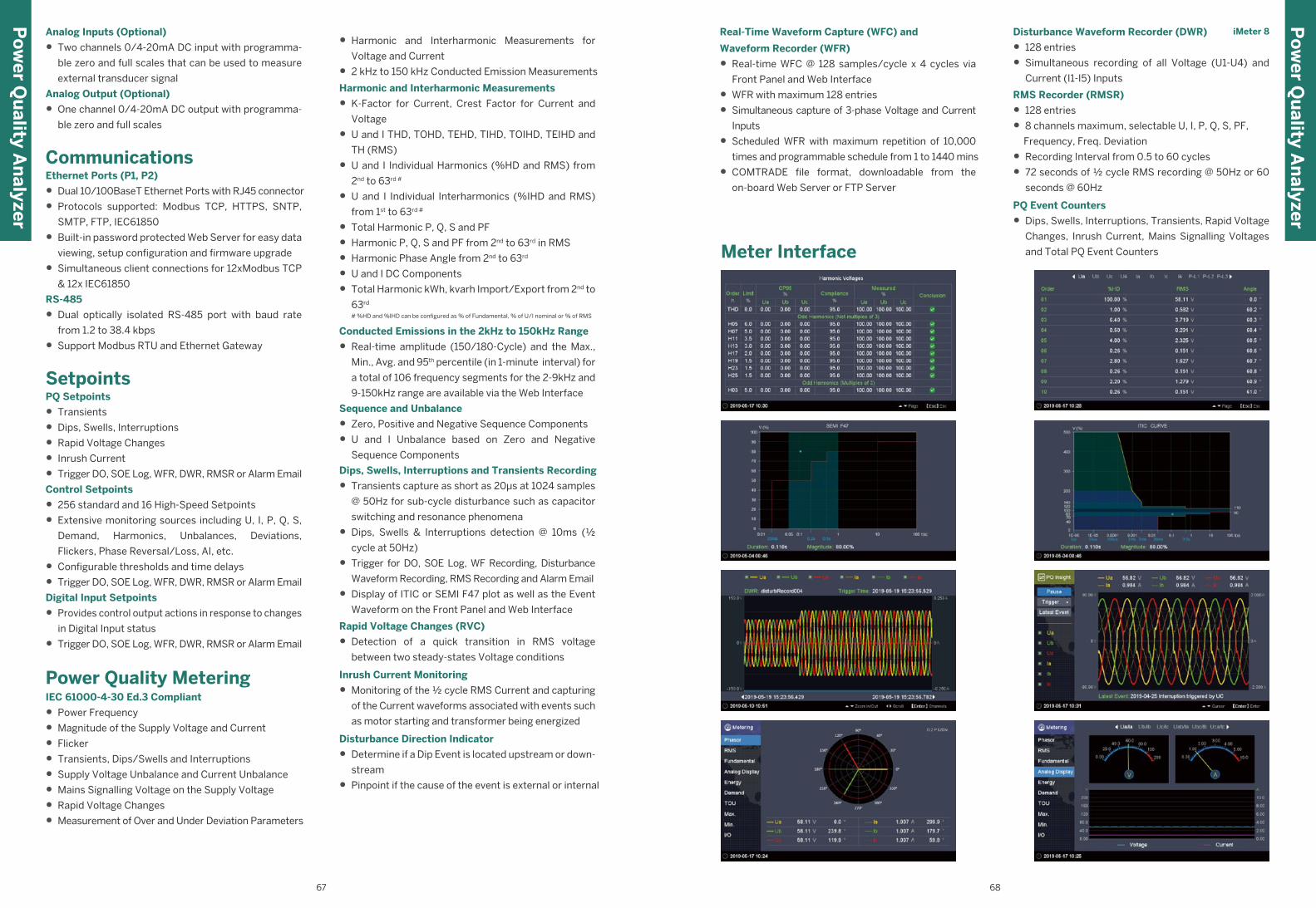
Disturbance Waveform Recorder (DWR)
• 128 entries
• Simultaneous recording of all Voltage (U1-U4) and
Current (I1-I5) Inputs
RMS Recorder (RMSR)
• 128 entries
• 8 channels maximum, selectable U, I, P, Q, S, PF,
Frequency, Freq. Deviation
• Recording Interval from 0.5 to 60 cycles
• 72 seconds of ½ cycle RMS recording @ 50Hz or 60
seconds @ 60Hz
PQ Event Counters
• Dips, Swells, Interruptions, Transients, Rapid Voltage
Changes, Inrush Current, Mains Signalling Voltages
and Total PQ Event Counters
Analog Inputs (Optional)
• Two channels 0/4-20mA DC input with programma-
ble zero and full scales that can be used to measure
external transducer signal
Analog Output (Optional)
• One channel 0/4-20mA DC output with programma-
ble zero and full scales
CommunicationsEthernet Ports (P1, P2)
• Dual 10/100BaseT Ethernet Ports with RJ45 connector
• Protocols supported: Modbus TCP, HTTPS, SNTP,
SMTP, FTP, IEC61850
• Built-in password protected Web Server for easy data
viewing, setup configuration and firmware upgrade
• Simultaneous client connections for 12xModbus TCP
& 12x IEC61850
RS-485
• Dual optically isolated RS-485 port with baud rate
from 1.2 to 38.4 kbps
• Support Modbus RTU and Ethernet Gateway
SetpointsPQ Setpoints
• Transients
• Dips, Swells, Interruptions
• Rapid Voltage Changes
• Inrush Current
• Trigger DO, SOE Log, WFR, DWR, RMSR or Alarm Email
Control Setpoints
• 256 standard and 16 High-Speed Setpoints
• Extensive monitoring sources including U, I, P, Q, S,
Demand, Harmonics, Unbalances, Deviations,
Flickers, Phase Reversal/Loss, AI, etc.
• Configurable thresholds and time delays
• Trigger DO, SOE Log, WFR, DWR, RMSR or Alarm Email
Digital Input Setpoints
• Provides control output actions in response to changes
in Digital Input status
• Trigger DO, SOE Log, WFR, DWR, RMSR or Alarm Email
Power Quality MeteringIEC 61000-4-30 Ed.3 Compliant
• Power Frequency
• Magnitude of the Supply Voltage and Current
• Flicker
• Transients, Dips/Swells and Interruptions
• Supply Voltage Unbalance and Current Unbalance
• Mains Signalling Voltage on the Supply Voltage
• Rapid Voltage Changes
• Measurement of Over and Under Deviation Parameters
• Harmonic and Interharmonic Measurements for
Voltage and Current
• 2 kHz to 150 kHz Conducted Emission Measurements
Harmonic and Interharmonic Measurements
• K-Factor for Current, Crest Factor for Current and
Voltage
• U and I THD, TOHD, TEHD, TIHD, TOIHD, TEIHD and
TH (RMS)
• U and I Individual Harmonics (%HD and RMS) from
2nd to 63rd #
• U and I Individual Interharmonics (%IHD and RMS)
from 1st to 63rd #
• Total Harmonic P, Q, S and PF
• Harmonic P, Q, S and PF from 2nd to 63rd in RMS
• Harmonic Phase Angle from 2nd to 63rd
• U and I DC Components
• Total Harmonic kWh, kvarh Import/Export from 2nd to
63rd
# %HD and %IHD can be configured as % of Fundamental, % of U/I nominal or % of RMS
Conducted Emissions in the 2kHz to 150kHz Range
• Real-time amplitude (150/180-Cycle) and the Max.,
Min., Avg. and 95th percentile (in 1-minute interval) for
a total of 106 frequency segments for the 2-9kHz and
9-150kHz range are available via the Web Interface
Sequence and Unbalance
• Zero, Positive and Negative Sequence Components
• U and I Unbalance based on Zero and Negative
Sequence Components
Dips, Swells, Interruptions and Transients Recording
• Transients capture as short as 20µs at 1024 samples
@ 50Hz for sub-cycle disturbance such as capacitor
switching and resonance phenomena
• Dips, Swells & Interruptions detection @ 10ms (½
cycle at 50Hz)
• Trigger for DO, SOE Log, WF Recording, Disturbance
Waveform Recording, RMS Recording and Alarm Email
• Display of ITIC or SEMI F47 plot as well as the Event
Waveform on the Front Panel and Web Interface
Rapid Voltage Changes (RVC)
• Detection of a quick transition in RMS voltage
between two steady-states Voltage conditions
Inrush Current Monitoring
• Monitoring of the ½ cycle RMS Current and capturing
of the Current waveforms associated with events such
as motor starting and transformer being energized
Disturbance Direction Indicator
• Determine if a Dip Event is located upstream or down-
stream
• Pinpoint if the cause of the event is external or internal
iMeter 8
Po
wer Q
uality A
nalyzer
Real-Time Waveform Capture (WFC) and
Waveform Recorder (WFR)
• Real-time WFC @ 128 samples/cycle x 4 cycles via
Front Panel and Web Interface
• WFR with maximum 128 entries
• Simultaneous capture of 3-phase Voltage and Current
Inputs
• Scheduled WFR with maximum repetition of 10,000
times and programmable schedule from 1 to 1440 mins
• COMTRADE file format, downloadable from the
on-board Web Server or FTP Server
Meter Interface
Po
wer Q
uality A
nalyzer
67 68
Power Supply (L+, N-)
Digital Inputs (DIC, DI1 to DI8 or optional DI1 to DI16)
Standard
Burden
Overvoltage Category
95-250VAC/VDC ±10%, 47-440Hz
< 12W
Digital Outputs-Form A Relay (DO1 to DO3 or optional DO1 to DO7)
Type
Loading
Form A Mechanical Relay
5A @ 250VAC/30VDC
Digital Outputs-Form C Relay (Alarm 1, 2, 3)
Type
Loading
Form C Mechanical Relay
8A @ 250VAC/24VDC
Optional Analog Input (AI1+, AI1-, AI2+, AI2-)
Type
Overload
0-20/4-20 mA DC
24 mA maximum
Optional Analog Output (AO+, AO-)
Type
Loading
Overload
0-20/4-20 mA
500Ω maximum
24 mA maximum
CATIII 300V
Pulse Outputs (E1+, E1-, E2+, E2-, E3+, E3-, E4+, E4-)
Standard
Optional
Sampling
Hysteresis
Dry contact, 24VDC internally wetted
110V/220V AC/DC externally wetted
1000Hz
1ms minimum
Type
Isolation
Maximum Load Voltage
Maximum Forward Current
Form A Solid State Relay
Optical
30 VDC
4mA
Operating Temperature
Storage Temperature
Humidity
Atmospheric Pressure
Pollution Degree
Measurement Category
-40°C to 85°C
5% to 95% non-condensing
63 kPa to 110 kPa
Environmental Conditions
-25°C to 70°C
2
1000V CAT III
Unit Dimensions
Panel Cutout
IP Rating
Mechanical Characteristics
186x186 mm
192x192x182.4 mm
52
iMeter 8
Parameters Accuracy Resolution
Voltage (U)
I1, I2, I3
I5
P, Q, S
I4
kvarh
Phase Angle
PF
Voltage Unbalance
Pst, Plt
Current Unbalance
±0.1%
±0.1%
±0.1%
±0.5%
±0.2%
SCCPA Option: ±0.5%
SCCPA Option: ±0.1% + Error of SCCP
SCCPA Option: IEC 62053-21 Class 1
IEC 62053-24 Class 0.5S
±0.2%
SCCPA Option: IEC 62053-24 Class 1
IEC 62053-22 Class 0.2S
SCCPA Option: ±0.5%
±0.2
SCCPA Option: ±0.2 + Phase Error of SCCP
±0.1%
±0.5%
±5%
0.001V
0.001A
0.001kX
0.001
0.1kvarh
0.1kXh
0.1°
0.01%
0.01%
0.01%
Frequency
K-Factor
Harmonics
±0.003Hz
IEC 61000-4-7 Class A
IEC 61000-4-7 Class A
0.001Hz
0.001
0.001
Accuracy
kWh, kVAh
Voltage Inputs (V1, V2, V3, VN, V4, V4N)
Overload
Frequency
Primary
V4 Primary
Secondary
Technical SpecificationsTechnical Specifications
PT Ratio
Burden
Standard (Un)
Range
V4 Secondary
2xUn continuous, 4xUn for 1s
< 0.5VA/per phase
400ULN/690ULL +20%
1% to 200% Un for 400ULN nominal
1-1,000,000V
1-1,000,000V
1-1,500V
1-1,500V
40Hz-60Hz @ 50Hz, 48Hz-72Hz @ 60Hz
Current Inputs (I11, I12, I21, I22, I31, I32, I41, I42, I51, I52)
Starting Current
SCCP-50A-500mV
SCCP-500A-500mV
SCCP-200A-200mV
SCCP Options
Overload
Burden
Standard (In)
Range
SCCP-5000A-500mV
0.1% In
4xIn continuous, 20xIn for 1s
< 0.5VA/per phase @ 5A
< 0.1VA/per phase @ 1A
5A (Standard), 1A (Optional)
1% to 400% In
5A/50A (In/Imax), maximum 500mV Output
500A Imax, maximum 500mV Output
20A/200A (In/Imax), maximum 200mV Output
Selectable 500A/5000A (Imax)Rogowski Coil, maximum 500mV Output
Primary
I4 Primary
SecondaryCT Ratio
I4 Secondary
1-30,000V
1-30,000V
1-50A
1-50A
Po
wer Q
uality A
nalyzer
Po
wer Q
uality A
nalyzer
69 70
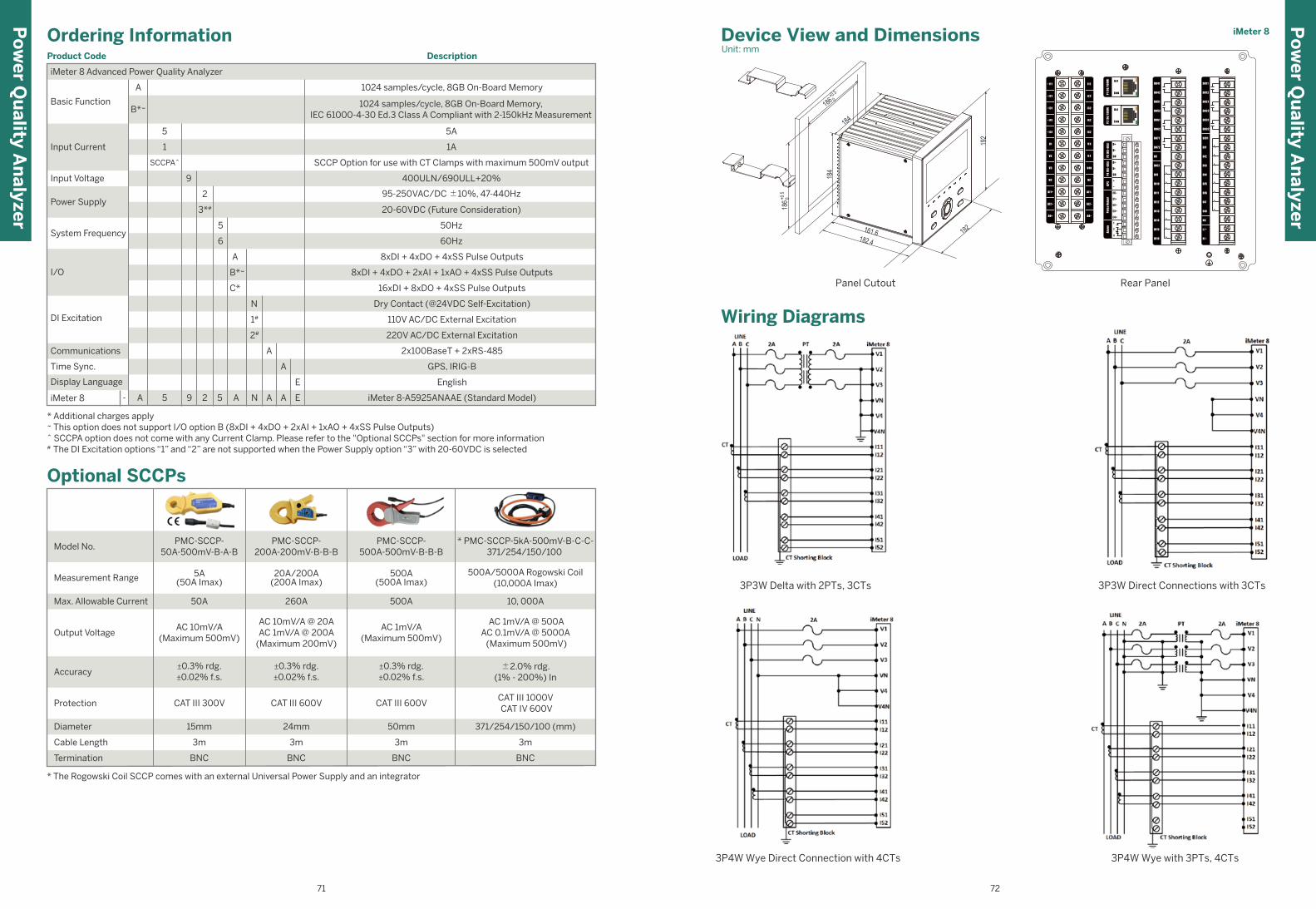
* The Rogowski Coil SCCP comes with an external Universal Power Supply and an integrator
Optional SCCPs
BNC BNC
3m 3m
BNC
3m
15mm 24mm 50mm
CAT III 600V CAT III 600VCAT III 300V
±0.3% rdg.±0.02% f.s.
±0.3% rdg.±0.02% f.s.
±0.3% rdg.±0.02% f.s.
AC 10mV/A(Maximum 500mV)
AC 10mV/A @ 20AAC 1mV/A @ 200A
(Maximum 200mV)
AC 1mV/A(Maximum 500mV)
50A 260A 500A
5A(50A Imax)
20A/200A(200A Imax)
500A(500A Imax)
PMC-SCCP-50A-500mV-B-A-B
Model No.PMC-SCCP-
200A-200mV-B-B-BPMC-SCCP-
500A-500mV-B-B-B
Measurement Range
Max. Allowable Current
Output Voltage
Accuracy
Protection
Diameter
Cable Length
Termination BNC
3m
371/254/150/100 (mm)
CAT III 1000V CAT IV 600V
±2.0% rdg.(1% - 200%) In
AC 1mV/A @ 500AAC 0.1mV/A @ 5000A (Maximum 500mV)
10, 000A
500A/5000A Rogowski Coil(10,000A Imax)
* PMC-SCCP-5kA-500mV-B-C-C-371/254/150/100
Ordering InformationProduct Code Description
Basic Function
Input Voltage
Power Supply
DI Excitation
Communications
Time Sync.
Display Language
I/O
16xDI + 8xDO + 4xSS Pulse Outputs
Dry Contact (@24VDC Self-Excitation)
110V AC/DC External Excitation
English
Input Current
iMeter 8 Advanced Power Quality Analyzer
1A
SCCP Option for use with CT Clamps with maximum 500mV output
System Frequency
400ULN/690ULL+20%
95-250VAC/DC ±10%, 47-440Hz
20-60VDC (Future Consideration)
50Hz
60Hz
8xDI + 4xDO + 4xSS Pulse Outputs
8xDI + 4xDO + 2xAI + 1xAO + 4xSS Pulse Outputs
220V AC/DC External Excitation
2x100BaseT + 2xRS-485
GPS, IRIG-B
1024 samples/cycle, 8GB On-Board Memory
1024 samples/cycle, 8GB On-Board Memory,IEC 61000-4-30 Ed.3 Class A Compliant with 2-150kHz Measurement
5A
* Additional charges apply~ This option does not support I/O option B (8xDI + 4xDO + 2xAI + 1xAO + 4xSS Pulse Outputs)^ SCCPA option does not come with any Current Clamp. Please refer to the "Optional SCCPs" section for more information# The DI Excitation options “1” and “2” are not supported when the Power Supply option “3” with 20-60VDC is selected
1
SCCPA^
9
2
3*#
5
6
A
B*~
C*
N
1#
2#
A
A
iMeter 8 - iMeter 8-A5925ANAAE (Standard Model)A 5 9 2 5 A N A EA
E
A
B*~
5
iMeter 8
1
2
3
V 4
V N
V4N
Wiring Diagrams
3P3W Delta with 2PTs, 3CTs 3P3W Direct Connections with 3CTs
3P4W Wye Direct Connection with 4CTs
Device View and DimensionsUnit: mm
Panel Cutout Rear Panel
3P4W Wye with 3PTs, 4CTs
Po
wer Q
uality A
nalyzer
Po
wer Q
uality A
nalyzer
71 72
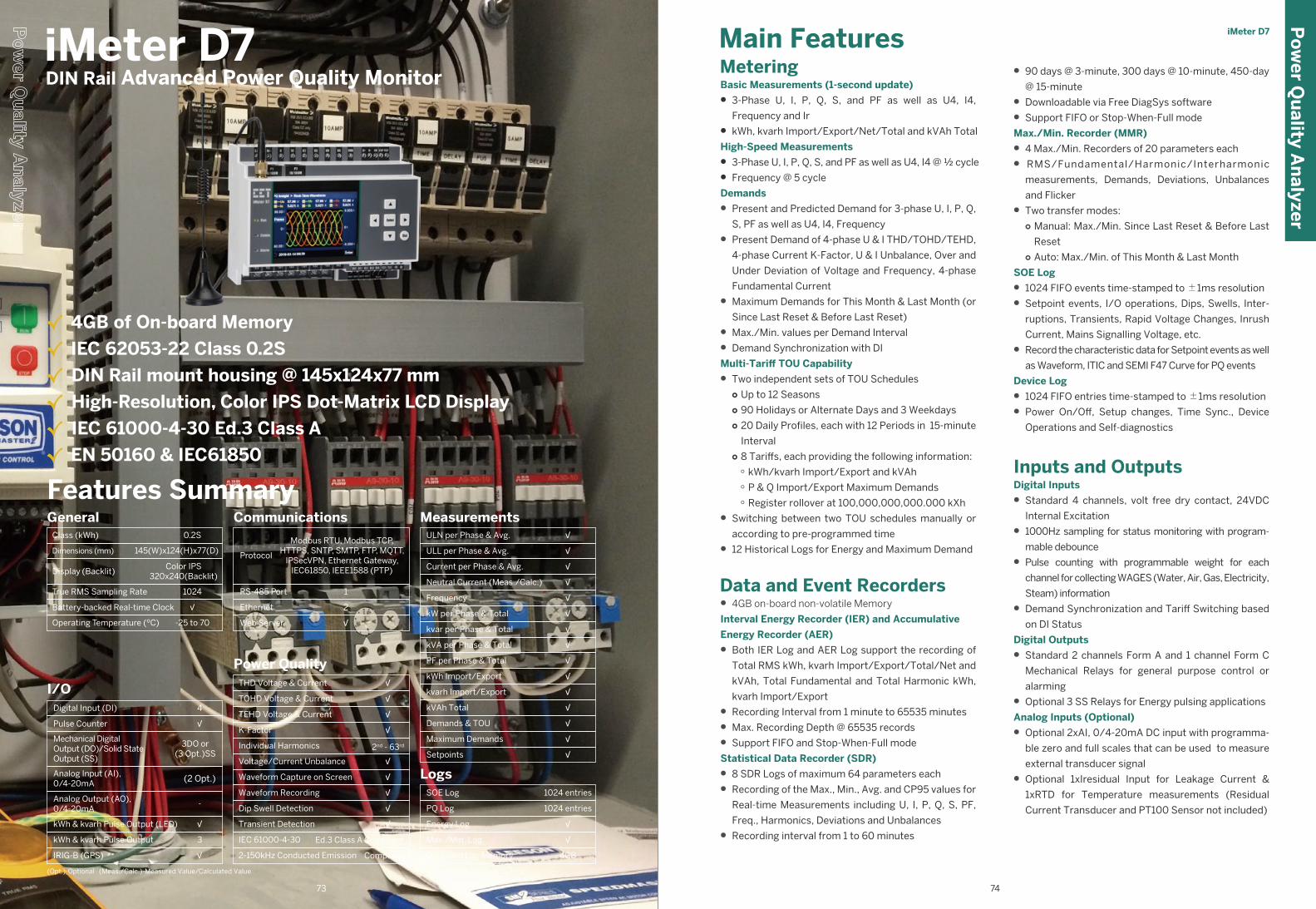
Features Summary
Class (kWh)
Operating Temperature (ºC)
Dimensions (mm)
Display (Backlit)
True RMS Sampling Rate
Battery-backed Real-time Clock
General0.2S
-25 to 70
Color IPS320x240(Backlit)
√
145(W)x124(H)x77(D)
1024
I/O4
3DO or(3 Opt.)SS
-
3
(2 Opt.)
√
√
√
Digital Input (DI)
Pulse Counter
Mechanical DigitalOutput (DO)/Solid StateOutput (SS)
Analog Input (AI),0/4-20mA
Analog Output (AO),0/4-20mA
kWh & kvarh Pulse Output (LED)
kWh & kvarh Pulse Output
IRIG-B (GPS)
Communications
Protocol
Ethernet
Modbus RTU, Modbus TCP,HTTPS, SNTP, SMTP, FTP, MQTT,
IPSecVPN, Ethernet Gateway,IEC61850, IEEE1588 (PTP)
RS-485 Port 1
2
Web Server √
Power QualityTHD Voltage & Current
TOHD Voltage & Current
TEHD Voltage & Current
K-Factor
Individual Harmonics
Voltage/Current Unbalance
Waveform Capture on Screen
Waveform Recording
Dip Swell Detection
Transient Detection
√
√
2nd - 63rd
√
√
√
√
√
√
√
IEC 61000-4-30
2-150kHz Conducted Emission
Ed.3 Class A Compliant
Compliant
MeasurementsULN per Phase & Avg.
ULL per Phase & Avg.
Current per Phase & Avg.
Neutral Current (Meas./Calc.)
Frequency
kW per Phase & Total
kvar per Phase & Total
kVA per Phase & Total
PF per Phase & Total
kWh Import/Export
kvarh Import/Export
kVAh Total
Demands & TOU
Maximum Demands
Setpoints
√
√
√
√
√
√
√
√
√
√
√
√
√
√
√
LogsSOE Log
PQ Log
Energy Log
Max./Min. Log
On-board Log Memory
1024 entries
√
4GB
1024 entries
√
• 90 days @ 3-minute, 300 days @ 10-minute, 450-day
@ 15-minute
• Downloadable via Free DiagSys software
• Support FIFO or Stop-When-Full mode
Max./Min. Recorder (MMR)
• 4 Max./Min. Recorders of 20 parameters each
• RMS/Fundamental/Harmonic/Interharmonic
measurements, Demands, Deviations, Unbalances
and Flicker
• Two transfer modes: ○ Manual: Max./Min. Since Last Reset & Before Last
Reset○ Auto: Max./Min. of This Month & Last Month
SOE Log
• 1024 FIFO events time-stamped to ±1ms resolution
• Setpoint events, I/O operations, Dips, Swells, Inter-
ruptions, Transients, Rapid Voltage Changes, Inrush
Current, Mains Signalling Voltage, etc.
• Record the characteristic data for Setpoint events as well
as Waveform, ITIC and SEMI F47 Curve for PQ events
Device Log
• 1024 FIFO entries time-stamped to ±1ms resolution
• Power On/Off, Setup changes, Time Sync., Device
Operations and Self-diagnostics
Inputs and OutputsDigital Inputs
• Standard 4 channels, volt free dry contact, 24VDC
Internal Excitation
• 1000Hz sampling for status monitoring with program-
mable debounce
• Pulse counting with programmable weight for each
channel for collecting WAGES (Water, Air, Gas, Electricity,
Steam) information
• Demand Synchronization and Tariff Switching based
on DI Status
Digital Outputs
• Standard 2 channels Form A and 1 channel Form C
Mechanical Relays for general purpose control or
alarming
• Optional 3 SS Relays for Energy pulsing applications
Analog Inputs (Optional)
• Optional 2xAI, 0/4-20mA DC input with programma-
ble zero and full scales that can be used to measure
external transducer signal
• Optional 1xIresidual Input for Leakage Current &
1xRTD for Temperature measurements (Residual
Current Transducer and PT100 Sensor not included)
MeteringBasic Measurements (1-second update)
• 3-Phase U, I, P, Q, S, and PF as well as U4, I4,
Frequency and Ir
• kWh, kvarh Import/Export/Net/Total and kVAh Total
High-Speed Measurements
• 3-Phase U, I, P, Q, S, and PF as well as U4, I4 @ ½ cycle
• Frequency @ 5 cycle
Demands
• Present and Predicted Demand for 3-phase U, I, P, Q,
S, PF as well as U4, I4, Frequency
• Present Demand of 4-phase U & I THD/TOHD/TEHD,
4-phase Current K-Factor, U & I Unbalance, Over and
Under Deviation of Voltage and Frequency, 4-phase
Fundamental Current
• Maximum Demands for This Month & Last Month (or
Since Last Reset & Before Last Reset)
• Max./Min. values per Demand Interval
• Demand Synchronization with DI
Multi-Tariff TOU Capability
• Two independent sets of TOU Schedules○ Up to 12 Seasons ○ 90 Holidays or Alternate Days and 3 Weekdays○ 20 Daily Profiles, each with 12 Periods in 15-minute
Interval○ 8 Tariffs, each providing the following information:
○ kWh/kvarh Import/Export and kVAh○ P & Q Import/Export Maximum Demands○ Register rollover at 100,000,000,000.000 kXh
• Switching between two TOU schedules manually or
according to pre-programmed time
• 12 Historical Logs for Energy and Maximum Demand
Data and Event Recorders• 4GB on-board non-volatile Memory
Interval Energy Recorder (IER) and Accumulative
Energy Recorder (AER)
• Both IER Log and AER Log support the recording of
Total RMS kWh, kvarh Import/Export/Total/Net and
kVAh, Total Fundamental and Total Harmonic kWh,
kvarh Import/Export
• Recording Interval from 1 minute to 65535 minutes
• Max. Recording Depth @ 65535 records
• Support FIFO and Stop-When-Full mode
Statistical Data Recorder (SDR)
• 8 SDR Logs of maximum 64 parameters each
• Recording of the Max., Min., Avg. and CP95 values for
Real-time Measurements including U, I, P, Q, S, PF,
Freq., Harmonics, Deviations and Unbalances
• Recording interval from 1 to 60 minutes
Main Features
(Opt.)-Optional (Meas./Calc.)-Measured Value/Calculated Value
iMeter D7
iMeter D7 DIN Rail Advanced Power Quality Monitor
√ 4GB of On-board Memory
√ IEC 62053-22 Class 0.2S
√ DIN Rail mount housing @ 145x124x77 mm
√ High-Resolution, Color IPS Dot-Matrix LCD Display
√ IEC 61000-4-30 Ed.3 Class A
√ EN 50160 & IEC61850
Po
wer Q
uality A
nalyzer
73 74
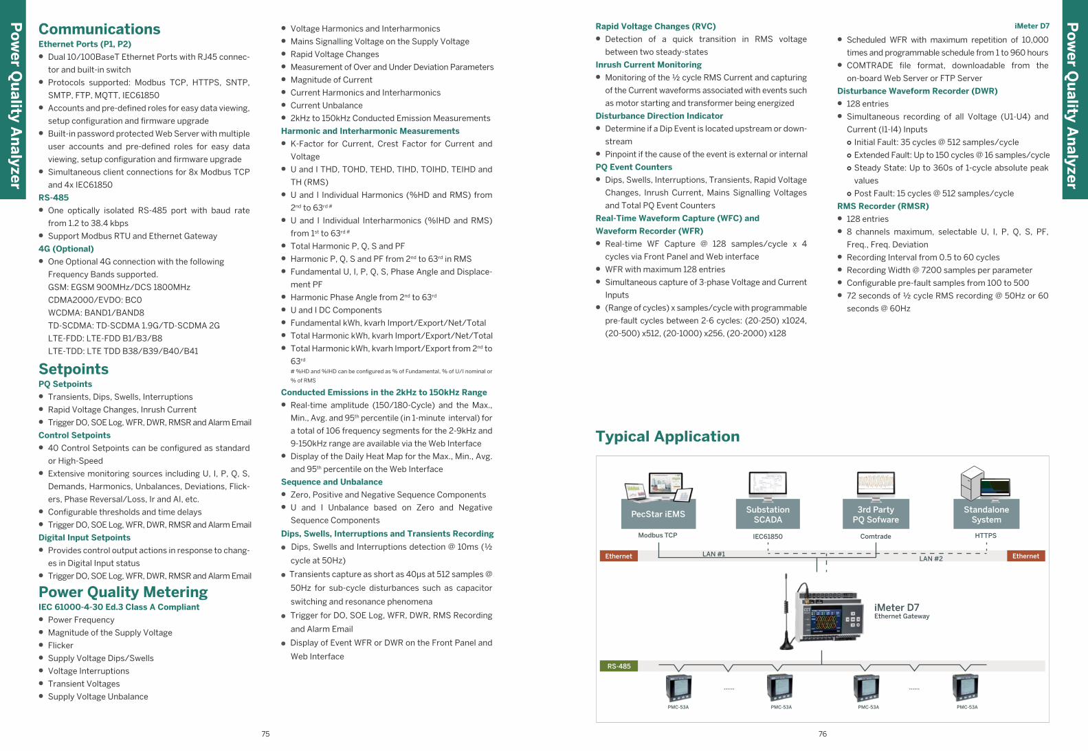
• Voltage Harmonics and Interharmonics
• Mains Signalling Voltage on the Supply Voltage
• Rapid Voltage Changes
• Measurement of Over and Under Deviation Parameters
• Magnitude of Current
• Current Harmonics and Interharmonics
• Current Unbalance
• 2kHz to 150kHz Conducted Emission Measurements
Harmonic and Interharmonic Measurements
• K-Factor for Current, Crest Factor for Current and
Voltage
• U and I THD, TOHD, TEHD, TIHD, TOIHD, TEIHD and
TH (RMS)
• U and I Individual Harmonics (%HD and RMS) from
2nd to 63rd #
• U and I Individual Interharmonics (%IHD and RMS)
from 1st to 63rd #
• Total Harmonic P, Q, S and PF
• Harmonic P, Q, S and PF from 2nd to 63rd in RMS
• Fundamental U, I, P, Q, S, Phase Angle and Displace-
ment PF
• Harmonic Phase Angle from 2nd to 63rd
• U and I DC Components
• Fundamental kWh, kvarh Import/Export/Net/Total
• Total Harmonic kWh, kvarh Import/Export/Net/Total
• Total Harmonic kWh, kvarh Import/Export from 2nd to
63rd
# %HD and %IHD can be configured as % of Fundamental, % of U/I nominal or
% of RMS
Conducted Emissions in the 2kHz to 150kHz Range
• Real-time amplitude (150/180-Cycle) and the Max.,
Min., Avg. and 95th percentile (in 1-minute interval) for
a total of 106 frequency segments for the 2-9kHz and
9-150kHz range are available via the Web Interface
• Display of the Daily Heat Map for the Max., Min., Avg.
and 95th percentile on the Web Interface
Sequence and Unbalance
• Zero, Positive and Negative Sequence Components
• U and I Unbalance based on Zero and Negative
Sequence Components
● Dips, Swells and Interruptions detection @ 10ms (½
cycle at 50Hz)
● Transients capture as short as 40µs at 512 samples @
50Hz for sub-cycle disturbances such as capacitor
switching and resonance phenomena
● Trigger for DO, SOE Log, WFR, DWR, RMS Recording
and Alarm Email
● Display of Event WFR or DWR on the Front Panel and
Web Interface
Typical Application
CommunicationsEthernet Ports (P1, P2)
• Dual 10/100BaseT Ethernet Ports with RJ45 connec-
tor and built-in switch
• Protocols supported: Modbus TCP, HTTPS, SNTP,
SMTP, FTP, MQTT, IEC61850
• Accounts and pre-defined roles for easy data viewing,
setup configuration and firmware upgrade
• Built-in password protected Web Server with multiple
user accounts and pre-defined roles for easy data
viewing, setup configuration and firmware upgrade
• Simultaneous client connections for 8x Modbus TCP
and 4x IEC61850
RS-485
• One optically isolated RS-485 port with baud rate
from 1.2 to 38.4 kbps
• Support Modbus RTU and Ethernet Gateway
4G (Optional)
• One Optional 4G connection with the following
Frequency Bands supported.
GSM: EGSM 900MHz/DCS 1800MHz
CDMA2000/EVDO: BC0
WCDMA: BAND1/BAND8
TD-SCDMA: TD-SCDMA 1.9G/TD-SCDMA 2G
LTE-FDD: LTE-FDD B1/B3/B8
LTE-TDD: LTE TDD B38/B39/B40/B41
SetpointsPQ Setpoints
• Transients, Dips, Swells, Interruptions
• Rapid Voltage Changes, Inrush Current
• Trigger DO, SOE Log, WFR, DWR, RMSR and Alarm Email
Control Setpoints
• 40 Control Setpoints can be configured as standard
or High-Speed
• Extensive monitoring sources including U, I, P, Q, S,
Demands, Harmonics, Unbalances, Deviations, Flick-
ers, Phase Reversal/Loss, Ir and AI, etc.
• Configurable thresholds and time delays
• Trigger DO, SOE Log, WFR, DWR, RMSR and Alarm Email
Digital Input Setpoints
• Provides control output actions in response to chang-
es in Digital Input status
• Trigger DO, SOE Log, WFR, DWR, RMSR and Alarm Email
Power Quality MeteringIEC 61000-4-30 Ed.3 Class A Compliant
• Power Frequency
• Magnitude of the Supply Voltage
• Flicker
• Supply Voltage Dips/Swells
• Voltage Interruptions
• Transient Voltages
• Supply Voltage Unbalance
• Scheduled WFR with maximum repetition of 10,000
times and programmable schedule from 1 to 960 hours
• COMTRADE file format, downloadable from the
on-board Web Server or FTP Server
Disturbance Waveform Recorder (DWR)
• 128 entries
• Simultaneous recording of all Voltage (U1-U4) and
Current (I1-I4) Inputs○ Initial Fault: 35 cycles @ 512 samples/cycle○ Extended Fault: Up to 150 cycles @ 16 samples/cycle○ Steady State: Up to 360s of 1-cycle absolute peak
values ○ Post Fault: 15 cycles @ 512 samples/cycle
RMS Recorder (RMSR)
• 128 entries
• 8 channels maximum, selectable U, I, P, Q, S, PF,
Freq., Freq. Deviation
• Recording Interval from 0.5 to 60 cycles
• Recording Width @ 7200 samples per parameter
• Configurable pre-fault samples from 100 to 500
• 72 seconds of ½ cycle RMS recording @ 50Hz or 60
seconds @ 60Hz
Rapid Voltage Changes (RVC)
• Detection of a quick transition in RMS voltage
between two steady-states
Inrush Current Monitoring
• Monitoring of the ½ cycle RMS Current and capturing
of the Current waveforms associated with events such
as motor starting and transformer being energized
Disturbance Direction Indicator
• Determine if a Dip Event is located upstream or down-
stream
• Pinpoint if the cause of the event is external or internal
PQ Event Counters
• Dips, Swells, Interruptions, Transients, Rapid Voltage
Changes, Inrush Current, Mains Signalling Voltages
and Total PQ Event Counters
Real-Time Waveform Capture (WFC) and
Waveform Recorder (WFR)
• Real-time WF Capture @ 128 samples/cycle x 4
cycles via Front Panel and Web interface
• WFR with maximum 128 entries
• Simultaneous capture of 3-phase Voltage and Current
Inputs
• (Range of cycles) x samples/cycle with programmable
pre-fault cycles between 2-6 cycles: (20-250) x1024,
(20-500) x512, (20-1000) x256, (20-2000) x128
Ethernet Ethernet
PecStar iEMS
Modbus TCP
LAN #1 LAN #2
HTTPS
Standalone System
PMC-53A PMC-53A PMC-53A PMC-53A
...... ......
RS-485
SubstationSCADA
IEC61850
3rd PartyPQ Sofware
Comtrade
Ethernet Gateway iMeter D7
Po
wer Q
uality A
nalyzer
Po
wer Q
uality A
nalyzer
iMeter D7
75 76
Dips, Swells, Interruptions and Transients Recording
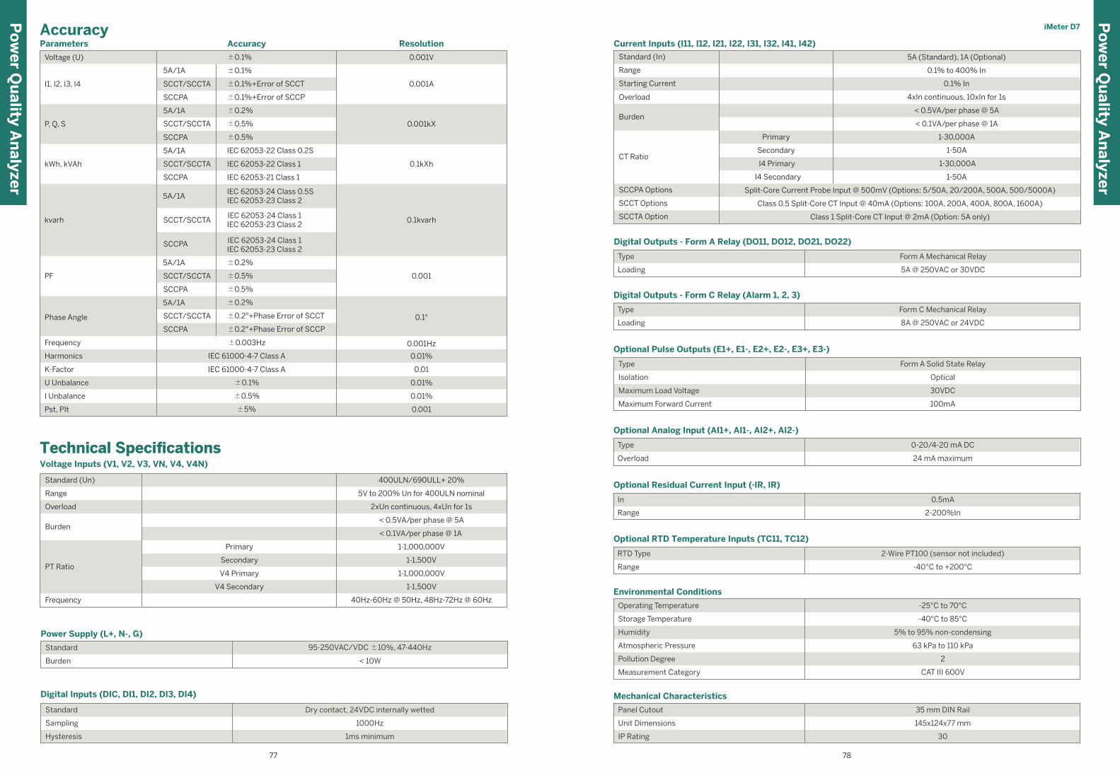
Po
wer Q
uality A
nalyzer
Po
wer Q
uality A
nalyzer
Voltage Inputs (V1, V2, V3, VN, V4, V4N)
Overload
Frequency
Primary
V4 Primary
Secondary
Technical SpecificationsTechnical Specifications
PT Ratio
Burden
Standard (Un)
Range
V4 Secondary
400ULN/690ULL+ 20%
5V to 200% Un for 400ULN nominal
2xUn continuous, 4xUn for 1s
1-1,000,000V
< 0.5VA/per phase @ 5A
< 0.1VA/per phase @ 1A
1-1,000,000V
1-1,500V
1-1,500V
40Hz-60Hz @ 50Hz, 48Hz-72Hz @ 60Hz
Humidity
Current Inputs (I11, I12, I21, I22, I31, I32, I41, I42)
Standard (In)
Range
Starting Current
Overload
Burden
CT Ratio
Primary
Secondary
I4 Primary
I4 Secondary
1-30,000A
1-50A
1-30,000A
1-50A
0.1% to 400% In
0.1% In
4xIn continuous, 10xIn for 1s
< 0.1VA/per phase @ 1A
< 0.5VA/per phase @ 5A
Split-Core Current Probe Input @ 500mV (Options: 5/50A, 20/200A, 500A, 500/5000A)
Class 0.5 Split-Core CT Input @ 40mA (Options: 100A, 200A, 400A, 800A, 1600A)
Class 1 Split-Core CT Input @ 2mA (Option: 5A only)
5A (Standard), 1A (Optional)
Digital Outputs - Form A Relay (DO11, DO12, DO21, DO22)
Type
Loading
Form A Mechanical Relay
5A @ 250VAC or 30VDC
Digital Outputs - Form C Relay (Alarm 1, 2, 3)
Type
Loading
Form C Mechanical Relay
8A @ 250VAC or 24VDC
Optional Analog Input (AI1+, AI1-, AI2+, AI2-)
Type
Overload
0-20/4-20 mA DC
24 mA maximum
Digital Inputs (DIC, DI1, DI2, DI3, DI4)
Standard
Sampling
Hysteresis
Dry contact, 24VDC internally wetted
1000Hz
1ms minimum
Optional Pulse Outputs (E1+, E1-, E2+, E2-, E3+, E3-)
Type
Isolation
Maximum Load Voltage
Maximum Forward Current
Optional RTD Temperature Inputs (TC11, TC12)
RTD Type
Range
2-Wire PT100 (sensor not included)
-40°C to +200°C
Optional Residual Current Input (·IR, IR)
In
Range
0.5mA
2-200%In
Form A Solid State Relay
Optical
30VDC
100mA
Operating Temperature
Storage Temperature
Humidity
Atmospheric Pressure
Pollution Degree
Measurement Category
-40°C to 85°C
5% to 95% non-condensing
63 kPa to 110 kPa
Environmental Conditions
-25°C to 70°C
2
CAT III 600V
Unit Dimensions
Panel Cutout
IP Rating
Mechanical Characteristics
35 mm DIN Rail
145x124x77 mm
30
Power Supply (L+, N-, G)
Standard
Burden
95-250VAC/VDC ±10%, 47-440Hz
< 10W
Parameters
Voltage (U)
5A/1A
5A/1A
5A/1A
5A/1A
SCCT/SCCTA
SCCPA
SCCT/SCCTA
SCCT/SCCTA
SCCT/SCCTA
SCCPA
SCCPA
SCCPA
I1, I2, I3, I4
±0.1%
±0.1%
±0.1%+Error of SCCT
±0.1%+Error of SCCP
IEC 62053-24 Class 0.5SIEC 62053-23 Class 2
IEC 62053-24 Class 1IEC 62053-23 Class 2
IEC 62053-24 Class 1IEC 62053-23 Class 2
±0.2%
±0.5%
±0.5%
IEC 62053-22 Class 0.2S
IEC 62053-22 Class 1
IEC 62053-21 Class 1
±0.5%
±0.5%
±0.2%
±0.2%
±0.2°+Phase Error of SCCT
±0.2°+Phase Error of SCCP
±0.1%
±0.5%
±5%
U Unbalance
I Unbalance
Pst, Plt
Frequency
Harmonics IEC 61000-4-7 Class A
±0.003Hz
IEC 61000-4-7 Class AK-Factor
ResolutionAccuracyAccuracy iMeter D7
7877
P, Q, S
kWh, kVAh
kvarh
PF
5A/1A
SCCT/SCCTA
SCCPA
5A/1A
SCCT/SCCTA
SCCPA
Phase Angle
0.001V
0.001A
0.001kX
0.1kXh
0.1kvarh
0.001
0.001Hz
0.01%
0.01
0.1°
0.01%
0.01%
0.001
SCCPA Options
SCCT Options
SCCTA Option
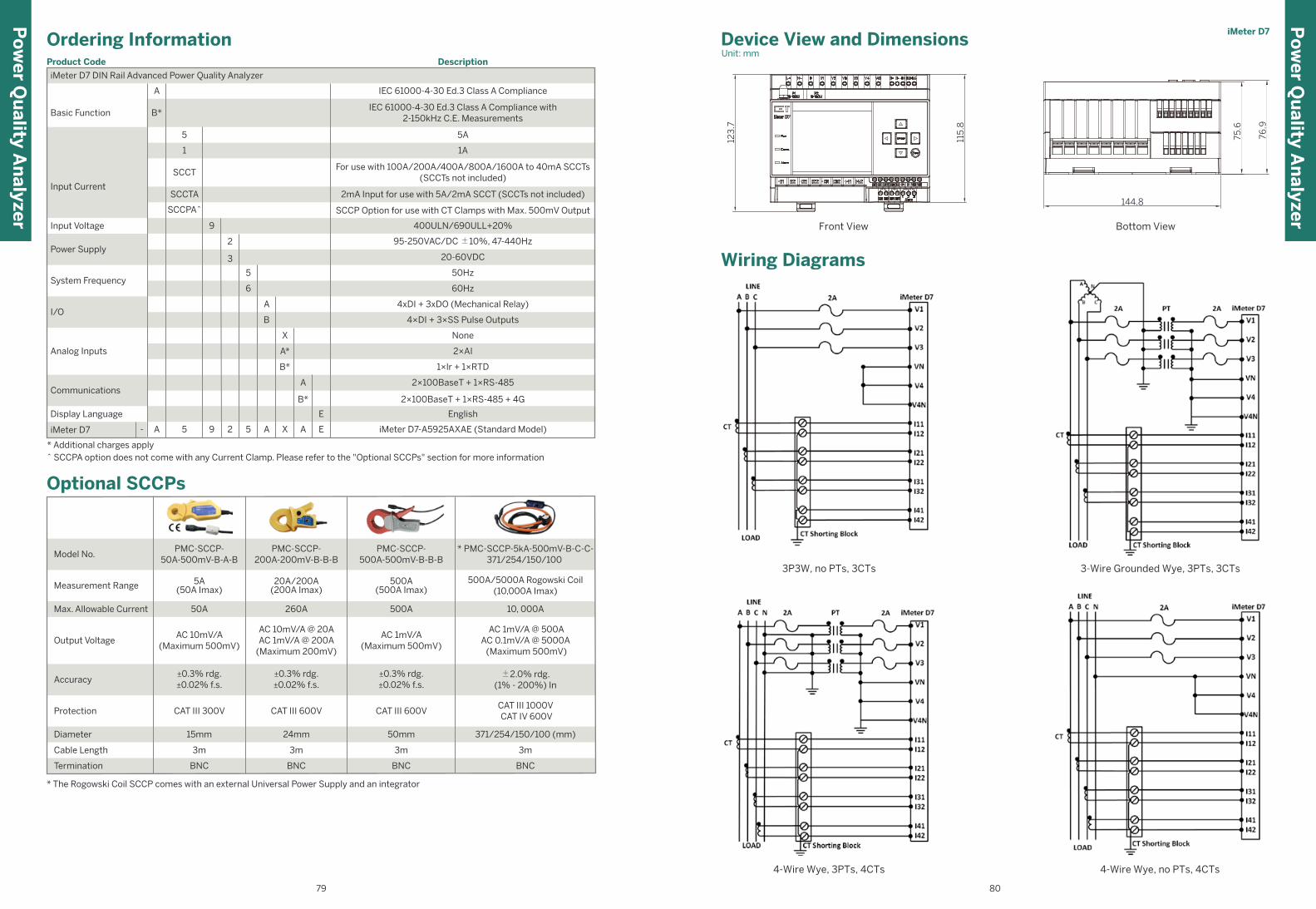
115
.8
123
.7
144.8
75.6
76.9
Device View and DimensionsUnit: mm
* Additional charges apply^ SCCPA option does not come with any Current Clamp. Please refer to the "Optional SCCPs" section for more information
Ordering InformationProduct Code Description
Basic Function
1
SCCPA^
Input CurrentSCCTA
SCCT
iMeter D7 DIN Rail Advanced Power Quality Analyzer
1A
SCCP Option for use with CT Clamps with Max. 500mV Output
2mA Input for use with 5A/2mA SCCT (SCCTs not included)
For use with 100A/200A/400A/800A/1600A to 40mA SCCTs(SCCTs not included)
Input Voltage
Power Supply
9
2
400ULN/690ULL+20%
95-250VAC/DC ±10%, 47-440Hz
Analog Inputs
Communications
I/O
None
2×AI
1×lr + 1×RTD
5
6
A
B
X
A*
B*
iMeter D7 A 5- iMeter D7-A5925AXAE (Standard Model)9 2 5 A X A E
A
B*
Display Language EnglishE
System Frequency50Hz
60Hz
4xDI + 3xDO (Mechanical Relay)
4×DI + 3×SS Pulse Outputs
2×100BaseT + 1×RS-485
2×100BaseT + 1×RS-485 + 4G
IEC 61000-4-30 Ed.3 Class A ComplianceA
B*IEC 61000-4-30 Ed.3 Class A Compliance with
2-150kHz C.E. Measurements
5 5A
* The Rogowski Coil SCCP comes with an external Universal Power Supply and an integrator
Optional SCCPs
BNC BNC
3m 3m
BNC
3m
15mm 24mm 50mm
CAT III 600V CAT III 600VCAT III 300V
±0.3% rdg.±0.02% f.s.
±0.3% rdg.±0.02% f.s.
±0.3% rdg.±0.02% f.s.
AC 10mV/A(Maximum 500mV)
AC 10mV/A @ 20AAC 1mV/A @ 200A
(Maximum 200mV)
AC 1mV/A(Maximum 500mV)
50A 260A 500A
5A(50A Imax)
20A/200A(200A Imax)
500A(500A Imax)
PMC-SCCP-50A-500mV-B-A-B
Model No.PMC-SCCP-
200A-200mV-B-B-BPMC-SCCP-
500A-500mV-B-B-B
Measurement Range
Max. Allowable Current
Output Voltage
Accuracy
Protection
Diameter
Cable Length
Termination BNC
3m
371/254/150/100 (mm)
CAT III 1000V CAT IV 600V
±2.0% rdg.(1% - 200%) In
AC 1mV/A @ 500AAC 0.1mV/A @ 5000A (Maximum 500mV)
10, 000A
500A/5000A Rogowski Coil(10,000A Imax)
* PMC-SCCP-5kA-500mV-B-C-C-371/254/150/100
Wiring Diagrams
3P3W, no PTs, 3CTs 3-Wire Grounded Wye, 3PTs, 3CTs
4-Wire Wye, 3PTs, 4CTs 4-Wire Wye, no PTs, 4CTs
Front View Bottom View
Po
wer Q
uality A
nalyzer
iMeter D7P
ow
er Qu
ality An
alyzer
79 80
3 20-60VDC
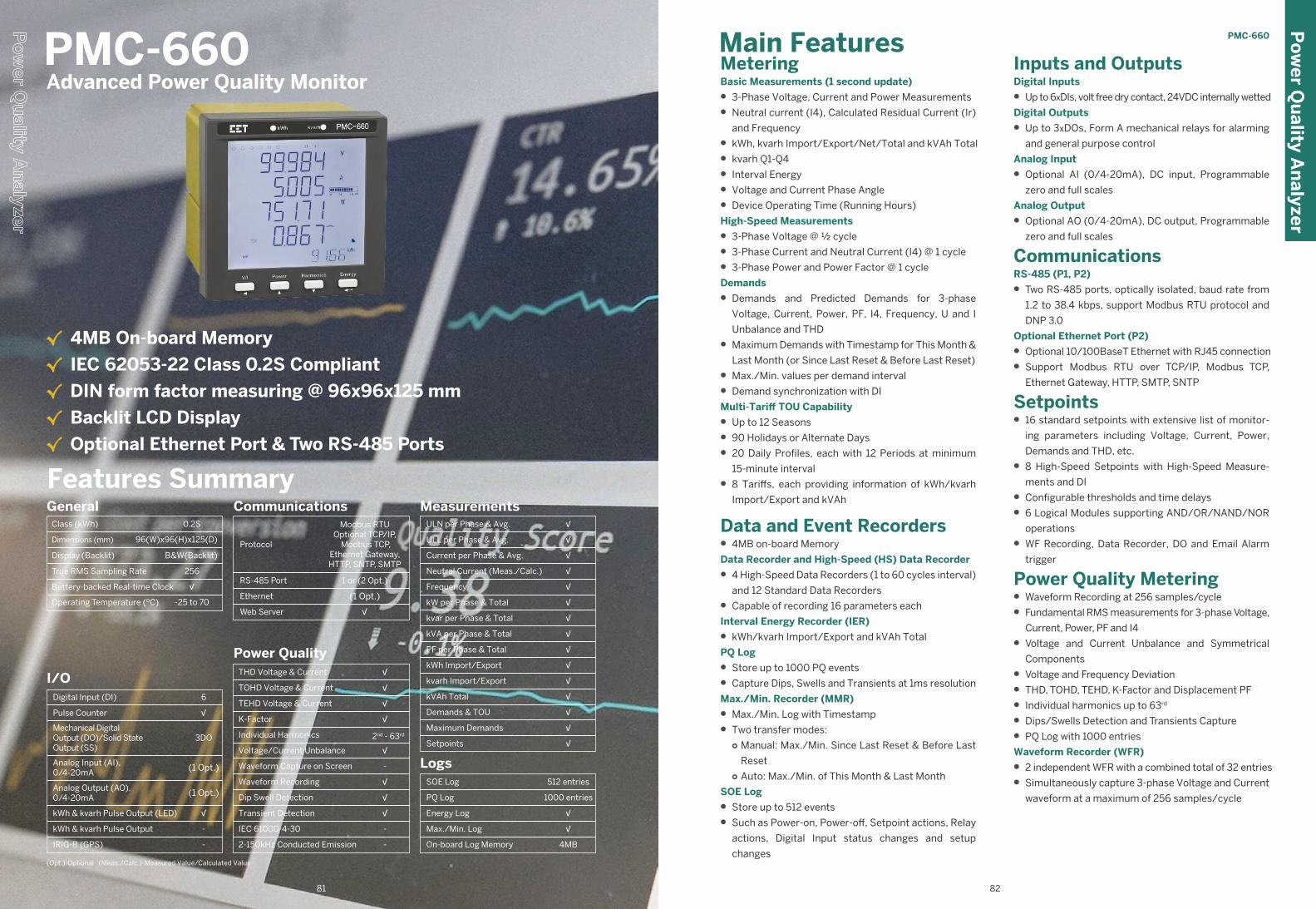
Inputs and OutputsDigital Inputs
• Up to 6xDIs, volt free dry contact, 24VDC internally wetted
Digital Outputs
• Up to 3xDOs, Form A mechanical relays for alarming
and general purpose control
Analog Input
• Optional AI (0/4-20mA), DC input, Programmable
zero and full scales
Analog Output
• Optional AO (0/4-20mA), DC output, Programmable
zero and full scales
CommunicationsRS-485 (P1, P2)
• Two RS-485 ports, optically isolated, baud rate from
1.2 to 38.4 kbps, support Modbus RTU protocol and
DNP 3.0
Optional Ethernet Port (P2)
• Optional 10/100BaseT Ethernet with RJ45 connection
• Support Modbus RTU over TCP/IP, Modbus TCP,
Ethernet Gateway, HTTP, SMTP, SNTP
Setpoints • 16 standard setpoints with extensive list of monitor-
ing parameters including Voltage, Current, Power,
Demands and THD, etc.
• 8 High-Speed Setpoints with High-Speed Measure-
ments and DI
• Configurable thresholds and time delays
• 6 Logical Modules supporting AND/OR/NAND/NOR
operations
• WF Recording, Data Recorder, DO and Email Alarm
trigger
Power Quality Metering• Waveform Recording at 256 samples/cycle
• Fundamental RMS measurements for 3-phase Voltage,
Current, Power, PF and I4
• Voltage and Current Unbalance and Symmetrical
Components
• Voltage and Frequency Deviation
• THD, TOHD, TEHD, K-Factor and Displacement PF
• Individual harmonics up to 63rd
• Dips/Swells Detection and Transients Capture
• PQ Log with 1000 entries
Waveform Recorder (WFR)
• 2 independent WFR with a combined total of 32 entries
• Simultaneously capture 3-phase Voltage and Current
waveform at a maximum of 256 samples/cycle
MeteringBasic Measurements (1 second update)
• 3-Phase Voltage, Current and Power Measurements
• Neutral current (I4), Calculated Residual Current (Ir)
and Frequency
• kWh, kvarh Import/Export/Net/Total and kVAh Total
• kvarh Q1-Q4
• Interval Energy
• Voltage and Current Phase Angle
• Device Operating Time (Running Hours)
High-Speed Measurements
• 3-Phase Voltage @ ½ cycle
• 3-Phase Current and Neutral Current (I4) @ 1 cycle
• 3-Phase Power and Power Factor @ 1 cycle
Demands
• Demands and Predicted Demands for 3-phase
Voltage, Current, Power, PF, I4, Frequency, U and I
Unbalance and THD
• Maximum Demands with Timestamp for This Month &
Last Month (or Since Last Reset & Before Last Reset)
• Max./Min. values per demand interval
• Demand synchronization with DI
Multi-Tariff TOU Capability
• Up to 12 Seasons
• 90 Holidays or Alternate Days
• 20 Daily Profiles, each with 12 Periods at minimum
15-minute interval
• 8 Tariffs, each providing information of kWh/kvarh
Import/Export and kVAh
Data and Event Recorders • 4MB on-board Memory
Data Recorder and High-Speed (HS) Data Recorder
• 4 High-Speed Data Recorders (1 to 60 cycles interval)
and 12 Standard Data Recorders
• Capable of recording 16 parameters each
Interval Energy Recorder (IER)
• kWh/kvarh Import/Export and kVAh Total
PQ Log
• Store up to 1000 PQ events
• Capture Dips, Swells and Transients at 1ms resolution
Max./Min. Recorder (MMR)
• Max./Min. Log with Timestamp
• Two transfer modes:○ Manual: Max./Min. Since Last Reset & Before Last
Reset○ Auto: Max./Min. of This Month & Last Month
SOE Log
• Store up to 512 events
• Such as Power-on, Power-off, Setpoint actions, Relay
actions, Digital Input status changes and setup
changes
Main Features PMC-660
PMC-660 Advanced Power Quality Monitor
(Opt.)-Optional (Meas./Calc.)-Measured Value/Calculated Value
Po
wer Q
uality A
nalyzer
82
√ 4MB On-board Memory
√ IEC 62053-22 Class 0.2S Compliant
√ DIN form factor measuring @ 96x96x125 mm
√ Backlit LCD Display
√ Optional Ethernet Port & Two RS-485 Ports
Power QualityTHD Voltage & Current
TOHD Voltage & Current
TEHD Voltage & Current
K-Factor
Individual Harmonics
Voltage/Current Unbalance
Waveform Capture on Screen
Waveform Recording
Dip Swell Detection
Transient Detection
√
√
2nd - 63rd
-
√
√
√
√
√
√
IEC 61000-4-30
2-150kHz Conducted Emission
-
-
Class (kWh)
Operating Temperature (ºC)
Dimensions (mm)
Display (Backlit)
True RMS Sampling Rate
Battery-backed Real-time Clock
General0.2S
-25 to 70
B&W(Backlit)
√
96(W)x96(H)x125(D)
256
I/O6
3DO
(1 Opt.)
-
(1 Opt.)
√
√
-
Digital Input (DI)
Pulse Counter
Mechanical DigitalOutput (DO)/Solid StateOutput (SS)
Analog Input (AI),0/4-20mA
Analog Output (AO),0/4-20mA
kWh & kvarh Pulse Output (LED)
kWh & kvarh Pulse Output
IRIG-B (GPS)
Communications
Protocol
Ethernet
Modbus RTUOptional TCP/IP,
Modbus TCP,Ethernet Gateway,HTTP, SNTP, SMTP
RS-485 Port 1 or (2 Opt.)
(1 Opt.)
Web Server √
MeasurementsULN per Phase & Avg.
ULL per Phase & Avg.
Current per Phase & Avg.
Neutral Current (Meas./Calc.)
Frequency
kW per Phase & Total
kvar per Phase & Total
kVA per Phase & Total
PF per Phase & Total
kWh Import/Export
kvarh Import/Export
kVAh Total
Demands & TOU
Maximum Demands
Setpoints
√
√
√
√
√
√
√
√
√
√
√
√
√
√
√
LogsSOE Log
PQ Log
Energy Log
Max./Min. Log
On-board Log Memory
512 entries
√
4MB
1000 entries
√
Features Summary
81
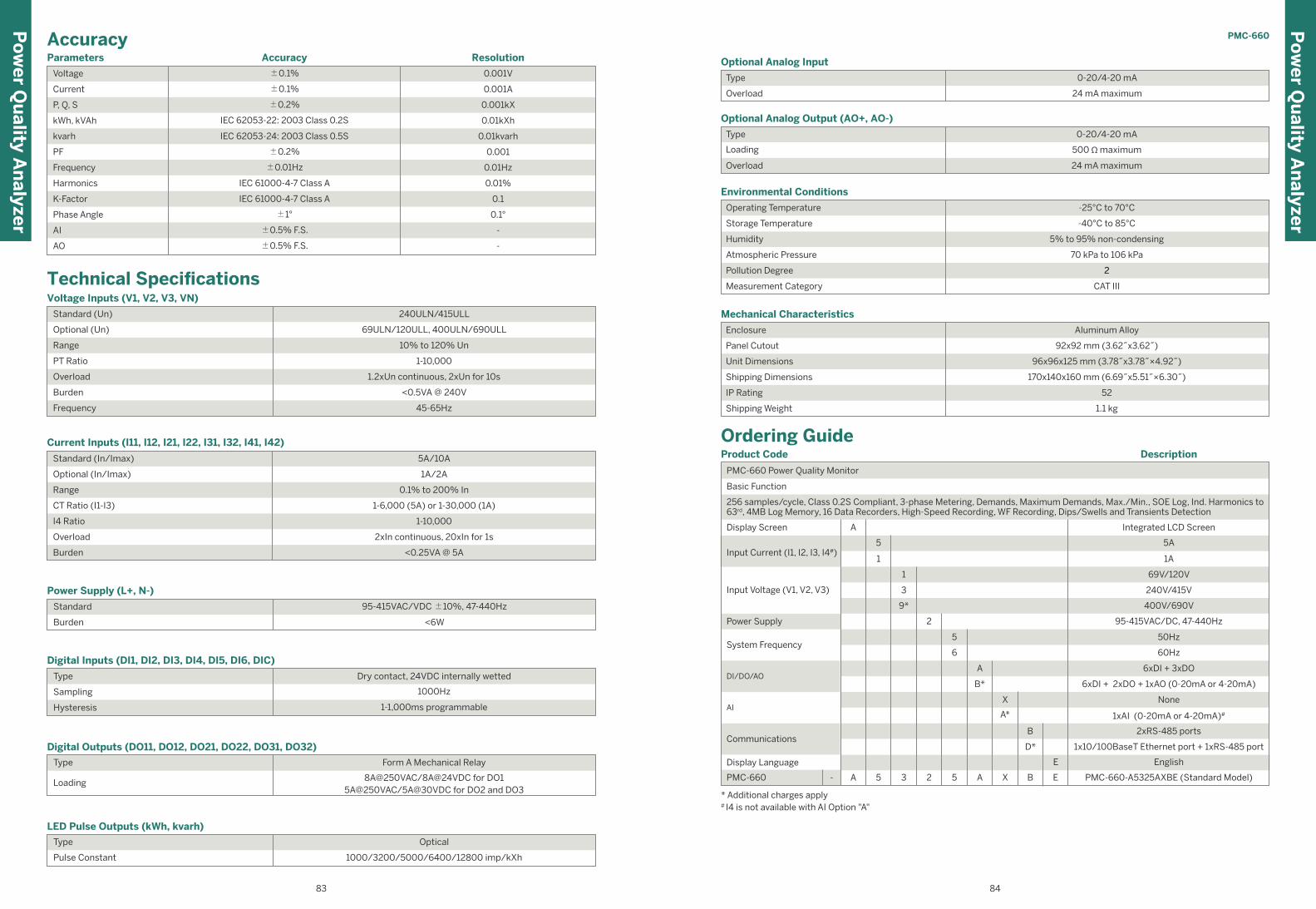
PMC-660
Technical SpecificationsVoltage Inputs (V1, V2, V3, VN)
Optional (Un)
Range
PT Ratio
Overload
Burden
Frequency
Standard (Un) 240ULN/415ULL
69ULN/120ULL, 400ULN/690ULL
10% to 120% Un
1-10,000
1.2xUn continuous, 2xUn for 10s
<0.5VA @ 240V
45-65Hz
Current Inputs (I11, I12, I21, I22, I31, I32, I41, I42)
5A/10A
Optional (In/Imax)
Range
CT Ratio (I1-I3)
I4 Ratio
Overload
Burden
1A/2A
0.1% to 200% In
1-6,000 (5A) or 1-30,000 (1A)
1-10,000
2xIn continuous, 20xIn for 1s
<0.25VA @ 5A
Standard (In/Imax)
Power Supply (L+, N-)
Standard
Burden
95-415VAC/VDC ±10%, 47-440Hz
<6W
Digital Inputs (DI1, DI2, DI3, DI4, DI5, DI6, DIC)
Type
Sampling
Hysteresis
Dry contact, 24VDC internally wetted
1000Hz
1-1,000ms programmable
Digital Outputs (DO11, DO12, DO21, DO22, DO31, DO32)
Type
Loading
Form A Mechanical Relay
8A@250VAC/8A@24VDC for DO15A@250VAC/5A@30VDC for DO2 and DO3
LED Pulse Outputs (kWh, kvarh)
Type
Pulse Constant
Optical
1000/3200/5000/6400/12800 imp/kXh
Parameters
Voltage ±0.1%
±0.1%
±0.2%
IEC 62053-22: 2003 Class 0.2S
IEC 62053-24: 2003 Class 0.5S
±0.2%
±0.01Hz
IEC 61000-4-7 Class A
±1°
±0.5% F.S.
±0.5% F.S.
IEC 61000-4-7 Class A
Current
P, Q, S
kWh, kVAh
kvarh
PF
Frequency
Harmonics
K-Factor
Phase Angle
AI
AO
0.001V
0.001A
0.001kX
0.01kXh
0.01kvarh
0.001
0.01Hz
0.01%
0.1
0.1°
-
-
ResolutionAccuracy
Accuracy
Type
Overload
0-20/4-20 mA
24 mA maximum
Optional Analog Output (AO+, AO-)
Optional Analog Input
Type
Loading
Overload
0-20/4-20 mA
500 Ω maximum
24 mA maximum
Environmental Conditions
-25°C to 70°C
Storage Temperature
Humidity
Atmospheric Pressure
Pollution Degree
Measurement Category
-40°C to 85°C
5% to 95% non-condensing
70 kPa to 106 kPa
2
CAT III
Operating Temperature
Storage Temperature
Atmospheric Pressure
Measurement Category
-40°C to 85°C
70 kPa to 106 kPa
2
CAT III
Mechanical Characteristics
Aluminum Alloy
Panel Cutout
Unit Dimensions
Shipping Dimensions
IP Rating
Shipping Weight
92x92 mm (3.62˝x3.62˝)
96x96x125 mm (3.78˝x3.78˝×4.92˝)
170x140x160 mm (6.69˝x5.51˝×6.30˝)
52
Enclosure
1.1 kg
Ordering GuideProduct Code
PMC-660 Power Quality Monitor
256 samples/cycle, Class 0.2S Compliant, 3-phase Metering, Demands, Maximum Demands, Max./Min., SOE Log, Ind. Harmonics to63rd, 4MB Log Memory, 16 Data Recorders, High-Speed Recording, WF Recording, Dips/Swells and Transients Detection
Basic Function
Power Supply
System Frequency
DI/DO/AO
AI
Communications
Display Language
PMC-660
6xDI + 2xDO + 1xAO (0-20mA or 4-20mA)
English
PMC-660-A5325AXBE (Standard Model)
5A
Integrated LCD ScreenDisplay Screen
Input Current (I1, I2, I3, I4#)
Input Voltage (V1, V2, V3)
Description
* Additional charges apply# I4 is not available with AI Option "A"
1A
69V/120V
240V/415V
6xDI + 3xDO
95-415VAC/DC, 47-440Hz
400V/690V
50Hz
60Hz
None
1xAI (0-20mA or 4-20mA)#
2xRS-485 ports
1x10/100BaseT Ethernet port + 1xRS-485 port
5
5
5 A X B
E
E3
2
2
A
5
1
1
3
9*
6
A
B*
X
A*
B
D*
A-
Po
wer Q
uality A
nalyzer
Po
wer Q
uality A
nalyzer
83 84
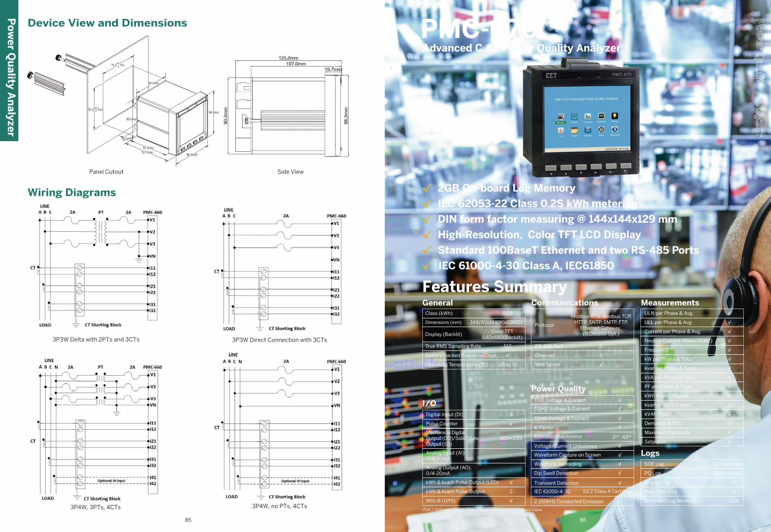
Features Summary
Class (kWh)
Operating Temperature (ºC)
Dimensions (mm)
Display (Backlit)
True RMS Sampling Rate
Battery-backed Real-time Clock
General0.2S
-25 to 70
Color TFT640x480(Backlit)
√
144(W)x144(H)x129(D)
512
I/O8
4DO+2SS
-
2
-
√
√
√
Digital Input (DI)
Pulse Counter
Mechanical DigitalOutput (DO)/Solid StateOutput (SS)
Analog Input (AI),0/4-20mA
Analog Output (AO),0/4-20mA
kWh & kvarh Pulse Output (LED)
kWh & kvarh Pulse Output
IRIG-B (GPS)
Communications
Protocol
Ethernet
Modbus RTU, Modbus TCP, HTTP, SNTP, SMTP, FTP,
Ethernet Gateway, (IEC61850 Opt.)
RS-485 Port 2
1
Web Server √
MeasurementsULN per Phase & Avg.
ULL per Phase & Avg.
Current per Phase & Avg.
Neutral Current (Meas./Calc.)
Frequency
kW per Phase & Total
kvar per Phase & Total
kVA per Phase & Total
PF per Phase & Total
kWh Import/Export
kvarh Import/Export
kVAh Total
Demands & TOU
Maximum Demands
Setpoints
√
√
√
√
√
√
√
√
√
√
√
√
√
√
√
LogsSOE Log
PQ Log
Energy Log
Max./Min. Log
On-board Log Memory
1024 entries
√
2GB
1024 entries
√
√ 2GB On-board Log Memory
√ IEC 62053-22 Class 0.2S kWh metering
√ DIN form factor measuring @ 144x144x129 mm
√ High-Resolution, Color TFT LCD Display
√ Standard 100BaseT Ethernet and two RS-485 Ports
√ IEC 61000-4-30 Class A, IEC61850
PMC-670 Advanced C & I Power Quality Analyzer
Device View and Dimensions
Side ViewPanel Cutout
Wiring Diagrams
3P3W Delta with 2PTs and 3CTs
3P4W, no PTs, 4CTs3P4W, 3PTs, 4CTs
3P3W Direct Connection with 3CTs
Po
wer Q
uality A
nalyzer
85 86
Power QualityTHD Voltage & Current
TOHD Voltage & Current
TEHD Voltage & Current
K-Factor
Individual Harmonics
Voltage/Current Unbalance
Waveform Capture on Screen
Waveform Recording
Dip Swell Detection
Transient Detection
√
√
2nd - 63rd
√
√
√
√
√
√
√
IEC 61000-4-30
2-150kHz Conducted Emission
Ed.2 Class A Certified
-
(Opt.)-Optional (Meas./Calc.)-Measured Value/Calculated Value

Dips, Swells, Interruptions and Transients Recording
• Transients capture as short as 40µs at 512 samples @
50Hz for sub-cycle disturbances such as capacitor
switching and resonance phenomena
• Dips and Swells detection @ 10ms (½ cycle at 50Hz)
• Trigger for RO, Data Recording, High-Speed Data
Recording, WF Recording, optional Disturbance Wave-
form Recording and Alarm Email
• Display of ITIC or SEMI F47 plot as well as the event
waveform on the Front Panel and Web Interface
Rapid Voltage Changes (RVC)
• Detection of a quick transition in RMS voltage
between two steady-states conditions
Optional Disturbance Direction Indicator
• Determine if a Dip Event is located upstream or down-
stream
• Pinpoint if the cause of the event is external or internal
Waveform Capture (WFC) and Waveform Recorder
(WFR)
• Real-time WF Capture @ 128 samples/cycle via Front
Panel display
• 2 independent WF Recorders with a combined total of
128 entries
• Simultaneous capture of 4-phase Voltage and Current
Inputs
• # of Cycles x Samples/Cycle (# of pre-fault cycles)○ 20x512 (6), 40x256 (12), 80x128 (24) 160x64 (48),
320x32 (96), 640x16 (192)
• COMTRADE file format, downloadable from the
on-board FTP Server
Disturbance Waveform Recording (DWR)
• Disturbance recording of all Voltage (U1-U4) and
Current (I1-I4) Inputs
PQ Event Counters
• Transients, Dips, Swells, Interruptions, Rapid Voltage
Changes, Mains Signalling Voltages and Total PQ
Event Counters
MeteringBasic Measurements (1-second update)
• 3-Phase Voltage, Current, Power, PF and Phase Angle
• kWh, kvarh Import/Export/Net/Total and kVAh Total
• U4, I4, Frequency
High-Speed Measurements for Event Detection
• 4-Phase Voltage, Current, Power, PF @ ½ cycle
• Frequency @ 5 cycles
Demands
• Present and Predicted Demand for 3-phase Voltage,
Current, Power, PF, U4, I4, Frequency
• Present Demand of 4-phase U & I THD/TOHD/TEH-
D/HD 2nd to HD 63rd, and 4-phase Current K-Factor
• Max./Min. values per Demand Interval
• Maximum Demands for This Month & Last Month (or
Since Last Reset & Before Last Reset)
• Demand synchronization with DI
Multi-Tariff TOU Capability
• Two independent sets of TOU Schedules○ Up to 12 Seasons○ 90 Holidays or Alternate Days and 3 Weekdays○ 20 Daily Profiles, each with 12 Periods in 15-minute
interval○ 8 Tariffs with Energy and Demand information
Data and Event Recorders• 2GB on-board log Memory
Interval Energy Recorder (IER)
• kWh, kvarh Import/Export and kVAh Total
• Programmable recording interval from 5 minutes to
60 minutes
• Support FIFO and Stop-When-Full mode
Data Recorder and High-Speed (HS) Data Recorder
• 16 Data Recorders and 4 HS Data Recorders of 16
parameters each
• Recording interval from 1s to 40 days for Data Record-
er and from 1/2 to 60 cycles for HS Data Recorder
• Programmable Sources
• Configurable Depths and Recording Offsets, maxi-
mum depths @ 65535
• Support FIFO or Stop-When-Full mode
Max./Min. Recorder (MMR)
• Logging of Max./Min. values for Real-time Measure-
ments such as U, I, kW, kvar, kVA, PF, Freq., Unbal-
ance, K-Factor, THD
• Two transfer modes: ○ Manual: Max./Min. Since Last Reset & Before Last
Reset○ Auto: Max./Min. of This Month & Last Month
PQ Log
• 1024 FIFO entries time-stamped to ±1ms resolution
Digital Input Setpoints
• Provides control output actions in response to chang-
es in Digital Input status
• Demand synchronization
• Trigger RO, SOE Log, Data Recording, High-Speed
Data Recording, WFR, optional DWR and Alarm Email
Power Quality MeteringPQ Parameters as per IEC 61000-4-30
• Power Frequency
• Magnitude of the Supply Voltage
• Flicker
• Supply Voltage Dips and Swells
• Voltage Interruptions
• Transient Voltages
• Supply Voltage Unbalance
• Voltage Harmonics and Interharmonics
• Mains Signalling Voltage on the Supply Voltage
• Rapid Voltage Changes
• Measurement of Over and Under Deviation Parameters
Harmonic and Interharmonic Measurements
• K-Factor for Current
• U and I THD, TOHD, TEHD
• U and I Individual Harmonics (%HD) from 2nd to 63rd#
• U and I Individual Interharmonics (%IHD) from 0 to
63rd#
• Fundamental U, I, kW, kvar, kVA and PF
• Fundamental kWh, kvarh Import/Export
• Total Harmonic kWh, kvarh Import/Export
• Total Harmonic kWh, Harmonic kvarh Import/Export
from 2nd to 63rd
# %HD and %IHD can be configured as % of Fundamental or % of RMS
Symmetrical Components and Unbalances
● Zero, Positive and Negative Sequence Components
● U and I Unbalance based on Zero and Negative
Sequence Components
• Transients, Dips/Swells, Disturbance Direction, Inter-
ruptions, Rapid Voltage Changes, Mains Signalling
Voltages, etc.
• Record the time and characteristic data of the
captured PQ event
SOE Log
• 1024 FIFO events time-stamped to ±1ms resolution
• Setup changes, System events, Setpoint events and
I/O operations
Inputs and OutputsDigital Inputs
• 8 channels, volt free dry contact, 24VDC internally wetted
• 1000Hz sampling
• External status monitoring with programmable debounce
• Pulse counting with programmable weight for each
channel for collecting WAGES (Water, Air, Gas, Electricity,
Steam) information
• Demand Synchronization
• Time-Sync via GPS's 1PPS output
Digital Outputs
• Standard 6 channels for control, alarming and pulsing
applications
• RO1-RO4: Form A Mechanical Relay
• DO1-DO2: Optically Isolated Solid State Relay
CommunicationsRS-485 (P1, P2)
• Optically isolated RS-485 port with baud rate from 1.2
to 38.4 kbps
• Modbus RTU protocol
• Time Sync. via P1 with GPS 1PPS or IRIG-B outputs
Ethernet Port (P3)
• 1x10/100BaseT with RJ45 connector
• Modbus TCP, HTTP, SNTP, FTP, SMTP
• Ethernet Gateway
• Optional IEC61850
Setpoints PQ Setpoints
• Provides control output actions in response to
Transients, Dips/Swells, Rapid Voltage Changes and
Harmonics
• Trigger RO, SOE Log, Data Recording, WFR or DWR
Control Setpoints
• 24 control setpoints with programmable Combina-
tional Logic
• 8 High-Speed Setpoints
• Extensive monitoring sources
• Configurable thresholds and time delays
• Trigger RO, SOE Log, Data Recorder, High-Speed
Data Recorder, Waveform Recorder and Alarm Email
Main Features PMC-670
Po
wer Q
uality A
nalyzer
Po
wer Q
uality A
nalyzer
87 88
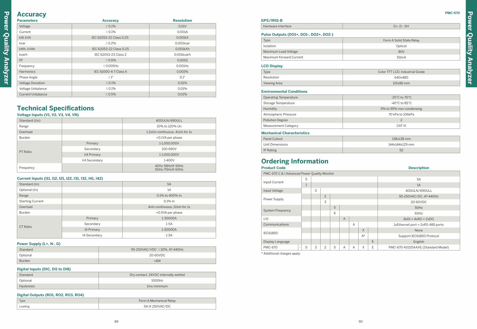
AccuracyParameters Accuracy Resolution
Voltage
Current
kW, kVA
kvar
kWh, kVAh
±0.1%
IEC 62053-22 Class 0.2S
±0.2%
IEC 62053-22 Class 0.2S
0.001A
0.001kX
0.001kvar
0.001kXh
kvarh IEC 62053-23 Class 2 0.001kvarh
PF ±0.5% 0.0001
Frequency ±0.005Hz 0.001Hz
Harmonics IEC 61000-4-7 Class A 0.001%
Phase Angle
Voltage Deviation
Voltage Unbalance
Current Unbalance
±1°
±0.1%
±0.1%
±0.5%
0.1°
0.01%
0.01%
±0.1% 0.01V
0.01%
Enclosure
IP Rating
Power Supply (L+, N-, G)
Optional
Standard
Burden
20-60VDC
<8W
Enclosure
IP Rating
Digital Inputs (DIC, DI1 to DI8)
Optional
Standard
Hysteresis
Dry contact, 24VDC internally wetted
1000Hz
1ms minimum
Enclosure
Digital Outputs (RO1, RO2, RO3, RO4)
Loading
Type
Technical Specifications
Humidity
Voltage Inputs (V1, V2, V3, V4, VN)
Standard (Un)
Range
Overload
Burden
PT Ratio
Primary
Secondary
V4 Primary
V4 Secondary
10% to 120% Un
1.2xUn continuous, 4xUn for 1s
<0.1VA per phase
1-1,000,000V
100-690V
1-1,000,000V
Frequency
1-400V
42Hz-58Hz@ 50Hz50Hz-70Hz@ 60Hz
Ordering InformationProduct Code
Power Supply
System Frequency
I/O
Communications
IEC61850
Display Language
PMC-670
6DI + 2DO + 1AO (0-20mA or 4-20mA)
English
5AInput Current
Input Voltage
Description
* Additional charges apply
1A
5A
400ULN/690ULL
1xEthernet port + 2xRS-485 ports
50Hz
20-60VDC
95-250VAC/DC, 47-440Hz
60Hz
8xDI + 4xRO + 2xDO
None
Support IEC61850 Protocol
English
PMC-670-A5325AAXE (Standard Model)
5
1
3
PMC-670 C & I Advanced Power Quality Monitor
2
3
5
6
3 A A X2 55- E
E
A
A
X
A*
Enclosure
IP Rating
Pulse Outputs (DO1+, DO1-, DO2+, DO2-)
Isolation
Type
Maximum Load Voltage
Maximum Forward Current
Optical
80V
50mA
Enclosure
IP Rating
Environmental Conditions
Storage Temperature
Operating Temperature
Humidity
Atmospheric Pressure
Pollution Degree
Measurement Category
-40°C to 85°C
5% to 95% non-condensing
70 kPa to 106kPa
2
CAT III
Enclosure
LCD Display
Viewing Area
Resolution
Type
640x480
Enclosure
Mechanical Characteristics
IP Rating
Unit Dimensions
Panel Cutout 138x138 mm
144x144x129 mm
52
Form A Solid State Relay
Color TFT LCD, Industrial Grade
115x86 mm
-25°C to 70°C
GPS/IRIG-B
Hardware Interface D+, D-, SH
Form A Mechanical Relay
5A @ 250VAC/DC
400ULN/690ULL
Humidity
Current Inputs (I11, I12, I21, I22, I31, I32, I41, I42)
Standard (In)
Optional (In)
Range
Starting Current
Overload
Burden
Primary
Secondary
I4 Primary
I4 Secondary
1A
0.1% to 400% In
0.1% In
4xIn continuous, 10xIn for 1s
<0.5VA per phase
1-30000A
CT Ratio1-5A
1-30000A
1-5A
5A
95-250VAC/VDC ±10%, 47-440Hz
PMC-670
Po
wer Q
uality A
nalyzer
Po
wer Q
uality A
nalyzer
9089

Features Summary
Class (kWh)
Operating Temperature (ºC)
Dimensions (mm)
Display (Backlit)
True RMS Sampling Rate
Battery-backed Real-time Clock
General0.2S
-25 to 70
Color TFT 640x480(Backlit)
√
192(W)x192(H)x187(D)
512 or (1024 Opt.)
I/O8
4DO+4SS
-
4
-
√
√
√
Digital Input (DI)
Pulse Counter
Mechanical DigitalOutput (DO)/Solid StateOutput (SS)
Analog Input (AI),0/4-20mA
Analog Output (AO),0/4-20mA
kWh & kvarh Pulse Output (LED)
kWh & kvarh Pulse Output
IRIG-B (GPS)
Communications
Protocol
Ethernet
Modbus RTU, Modbus TCP,HTTP, SNTP, SMTP, FTP,
Ethernet Gateway, (IEC61850 Opt.)
RS-485 Port (2 Opt.)
2
Web Server √
Power QualityTHD Voltage & Current
TOHD Voltage & Current
TEHD Voltage & Current
K-Factor
Individual Harmonics
Voltage/Current Unbalance
Waveform Capture on Screen
Waveform Recording
Dip Swell Detection
Transient Detection
√
√
2nd - 63rd
√
√
√
√
√
√
√
IEC 61000-4-30
2-150kHz Conducted Emission
Ed.2 Class A Certified
-
MeasurementsULN per Phase & Avg.
ULL per Phase & Avg.
Current per Phase & Avg.
Neutral Current (Meas./Calc.)
Frequency
kW per Phase & Total
kvar per Phase & Total
kVA per Phase & Total
PF per Phase & Total
kWh Import/Export
kvarh Import/Export
kVAh Total
Demands & TOU
Maximum Demands
Setpoints
√
√
√
√
√
√
√
√
√
√
√
√
√
√
√
LogsSOE Log
PQ Log
Energy Log
Max./Min. Log
On-board Log Memory
1024 entries
√
4GB or (8GB Opt.)
1024 entries
√
√ 4GB of On-board Log Memory (Optional 8GB)
√ IEC 62053-22 Class 0.2S kWh metering
√ DIN form factor measuring @ 96x96x88 mm
√ Backlit, Color TFT LCD Display
√ Dual Ethernet and two RS-485 Ports
√ IEC 61000-4-30 Class A
√ EN 50160 and optional IEC61850
PMC-680i Advanced Utility Power Quality Analyzer
Device View and DimensionsUnit: mm
Panel Cutout Rear Panel
138
136
136
8
138
+0
.5 0
109.1
129
+0.5 0
144
.1
144.1
Wiring Diagrams
3P3W Direct Connections with 3CTs
3P3W Delta with 2PTs, 3CTs3P4W Wye Direct Connection with 4CTs
3P4W Wye with 3PTs, 4CTs
(Opt.)-Optional (Meas./Calc.)-Measured Value/Calculated Value
Po
wer Q
uality A
nalyzer
91 92

Control Setpoints
• 256 Control Setpoints and 16 High-Speed Setpoints
• Extensive monitoring sources
• Configurable thresholds and time delays
• Trigger RO, SOE Log, Data Recorder, High-Speed
Data Recorder, Waveform Recorder and Alarm Email
Digital Input Setpoints
• Provides control output actions in response to chang-
es in Digital Input status
• Demand Synchronization and TOU Rate Change
• Trigger RO, Data Recording, High-Speed Data Recording,
WFR, DWR and Alarm Email
Power Quality MeteringIEC 61000-4-30 (Class A Certified)
• Power Frequency
• Magnitude of the Supply Voltage
• Flicker
• Supply Voltage Dips and Swells
• Voltage Interruptions
• Transient Voltages
• Supply Voltage Unbalance
• Voltage Harmonics and Interharmonics
• Mains Signalling Voltage on the Supply Voltage
• Rapid Voltage Changes
• Measurement of Over and Under Deviation
Harmonic and Interharmonic Measurements
• K-Factor for Current, Crest Factor for Current and
Voltage
• U and I THD, TOHD, TEHD
• U and I Individual Harmonics (%HD) from 2nd to 63rd#
• U and I Individual Interharmonics (%IHD) from 0 to
63rd #
• Harmonic kW, kvar, kVA and PF from 2nd to 63rd in RMS
• Fundamental U, I, kW, kvar, kVA and Displacement
• Fundamental kWh, kvarh Import/Export/Net/Total
• Total harmonic kWh, kvarh Import/Export/Net/Total
• Total Harmonic kWh, kvarh Import/Export from 2nd to
63rd (#%HD and %IHD can be configured as % of Fundamental, % of U/I nominal or %
of RMS)
Symmetrical Components and Unbalances
• Zero, Positive and Negative Sequence Components
• U and I Unbalance based on Zero and Negative
Sequence Components
• Transients capture as short as 40µs at 512 samples
or 20us at 1024 samples @ 50Hz for sub-cycle distur-
bances such as capacitor switching and resonance
phenomena
• Dips and Swells detection @ 10ms (½ cycle at 50Hz)
Dips, Swells, Interruptions and Transients Recording
• Trigger for RO, Data Recording and High-Speed Data
Recording, WF Recording, Disturbance Waveform
Recording and Alarm Email
• Display of ITIC or SEMI F47 plot as well as the event
waveform on the Front Panel and Web Interface
Rapid Voltage Changes (RVC)
• Detection of a quick transition in RMS voltage
between two steady-states Voltage conditions
Inrush Current Monitoring
• Monitoring of the ½ cycle RMS Current and capturing
of the Current waveforms associated with events such
as motor starting and transformer being energized
Disturbance Direction Indicator
• Determine if a Dip Event is located upstream or down-
stream
• Pinpoint if the cause of the event is external or internal
Waveform Capture (WFC) and Waveform
Recorder (WFR)
• Real-time WF Capture @ 128 samples/cycle via Front
Panel display
• WF Recorder with 128 entries
• Simultaneous capture of 3-phase Voltage and Current
inputs
• # of Cycles x Samples/Cycle with programmable # of
pre-fault cycles○ 10x1024*, 20x512, 40x256, 80x128, 160x64,
320x32, 640x16
• Extended recording for up to a maximum of 7 consec-
utive captures
• COMTRADE file format, downloadable from the
on-board FTP Server
* Only available for the 1024 sampling option
Disturbance Waveform Recorder (DWR)
• Disturbance recording of all Voltage (U1-U4) and
Current (I1-I5) Inputs
PQ Event Counters
• Transients, Dips, Swells, Interruptions, Rapid Voltage
Changes, Mains Signalling Voltages and Total PQ
Event Counters
Po
wer Q
uality A
nalyzer
PMC-680iMain FeaturesMeteringBasic Measurements (1-second update)
• 3-Phase Voltage, Current, Power, PF and Phase Angle
• kWh, kvarh Import/Export/Net/Total and kVAh Total
• U4, I4, I5, Frequency
• Configurable timestamped measurements include
10/12-cycle, 1-second, 3-second, 10-minute and 2-hour
High-Speed Measurements
• 3-Phase Voltages and Currents, U4, I4, I5, Power, PF
@ ½ cycle
• Frequency @ 1 cycle
Demands
• Present and Predicted Demand for 3-phase Voltage,
Current, Power, PF, U4, I4, I5, Frequency
• Present Demand of 4-phase U & I THD/TOHD/TEH-
D/HD 2nd to HD 63rd, and 4-phase Current K-Factor
• Max./Min. values per Demand Interval
• Maximum Demands for This Month & Last Month (or
Since Last Reset & Before Last Reset)
• Demand Synchronization with DI
Multi-Tariff TOU Capability
• Two independent sets of TOU Schedules, each supporting○ Up to 12 Seasons ○ 90 Holidays or Alternate Days and 3 Weekdays○ 20 Daily Profiles, each with 12 Periods in 1-minute
interval○ 8 Tariffs, each providing energy and Demand
information
Data and Event Recorders• 4GB on-board non-volatile Log Memory (Optional 8GB)
Interval Energy Recorder (IER)
• kWh, kvarh Import/Export and kVAh Total RMS, Total
Fundamental and Total Harmonic kWh, kvarh
Import/Export
• Programmable recording interval from 1 minute to
65535 minutes
Data Recorder and High-Speed (HS) Data Recorder
• 8 Data Recorders of 32 parameters each and 4 HS
Data Recorders of 16 parameters each
• Recording interval from 1s to 40 days for Data Recorder
and from 1/2 cycle to 60 cycles for HS Data Recorder
Statistical Data Recorder (SDR)
• Recording of the Max., Min., Avg. and 95th percentile for
Real-time measurements including U, I, Freq., Flicker,
Harmonics and Unbalances in 16 different recorders
• Recording interval from 1 minute to 60 minutes
• PQDIF file format, downloadable from the on-board
FTP Server
Max./Min. Recorder (MMR)
• Logging of Max./Min. values for Real-time measure-
ments such as U, I, kW, kvar, kVA, PF, Freq., Unbal-
ance, K-Factor, THD
• Two transfer modes: ○ Manual: Max./Min. Since Last Reset & Before Last
Reset○ Auto: Max./Min. of This Month & Last Month
PQ Log
• 1024 FIFO entries time-stamped to ±1ms resolution
• Transients, Dips/Swells, Disturbance Direction,
Interruptions, Rapid Voltage Changes, Mains Signal-
ling Voltages, etc.
• Record the time and characteristic data of the
captured PQ event
SOE Log
• 1024 FIFO events time-stamped to ±1ms resolution
• Setup changes, System events, Setpoint events and
I/O operations
Inputs and OutputsDigital Inputs
• 8 channels, volt free dry contact, 24VDC internally wetted
• 1000Hz sampling
Digital Outputs
• 8 channels for control, alarming and pulsing applications
CommunicationsEthernet Ports (P1, P2)
• Dual 10/100BaseT TCP/IP Ethernet Ports with RJ45
connector
• Simultaneous client connections for 10xModbus TCP
and 12x IEC61850
• Modbus TCP, HTTP, SNTP, SMTP, FTP
• Ethernet Gateway
• Optional IEC61850
RS-485 (P3, P4)
• Optically isolated RS-485 port with baud rate from 1.2
to 115.2 kbps
• Modbus RTU protocol
SetpointsPQ Setpoints
• Provides control output actions in response to
Transients, Dips/Swells, Rapid Voltage Changes,
Inrush Current and Harmonics
• Trigger RO, SOE Log, Data Recording, WFR or DWR
Po
wer Q
uality A
nalyzer
93 94
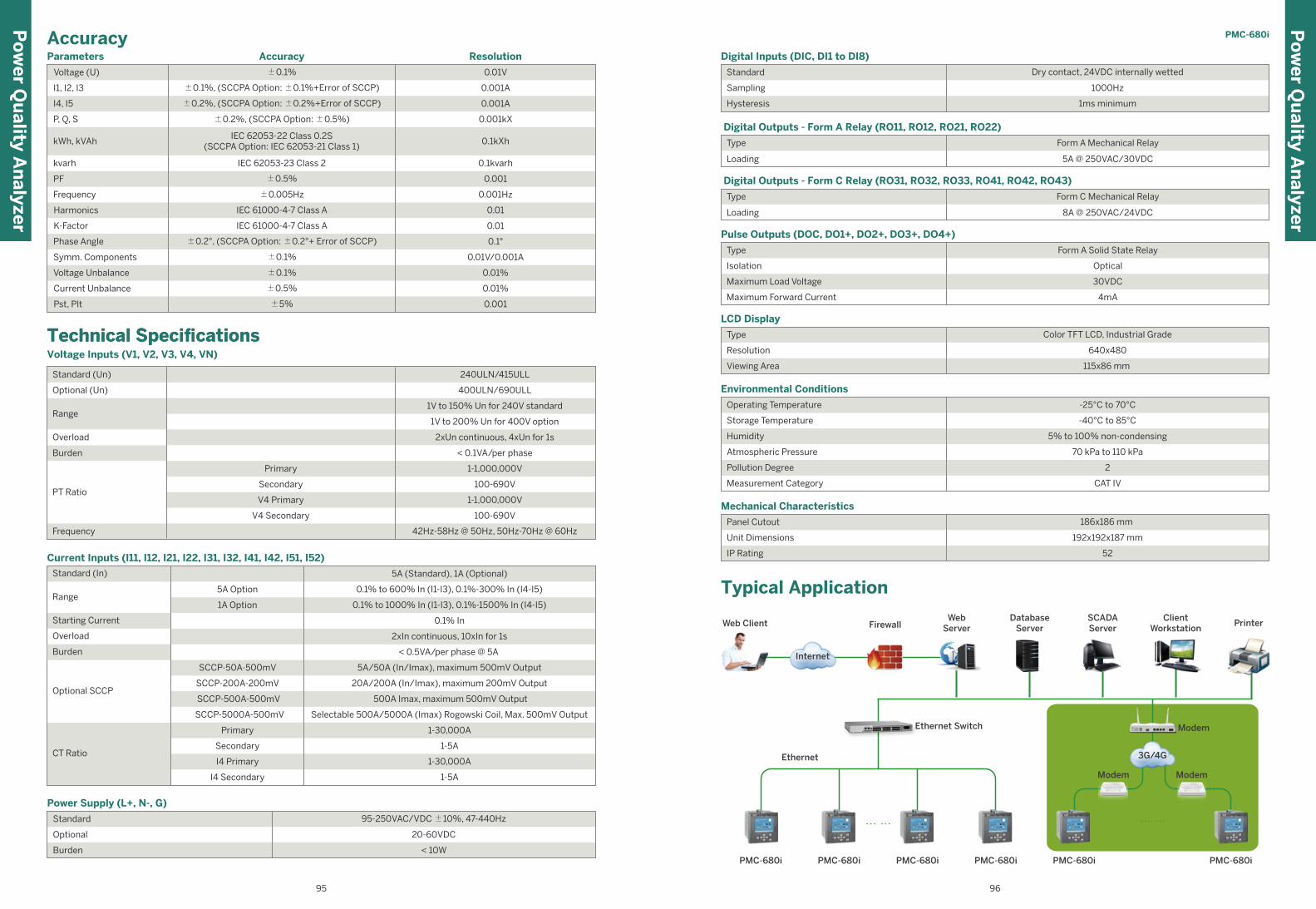
Type
Isolation
Maximum Load Voltage
Maximum Forward Current
Pulse Outputs (DOC, DO1+, DO2+, DO3+, DO4+)
Digital Outputs - Form A Relay (RO11, RO12, RO21, RO22)
Type
Loading
Form A Mechanical Relay
5A @ 250VAC/30VDC
Form A Solid State Relay
Optical
30VDC
4mA
Standard
Sampling
Hysteresis
Digital Inputs (DIC, DI1 to DI8)
Dry contact, 24VDC internally wetted
1000Hz
1ms minimum
Type
Resolution
Viewing Area
LCD Display
Color TFT LCD, Industrial Grade
640x480
115x86 mm
Panel Cutout
Unit Dimensions
IP Rating
Mechanical Characteristics
186x186 mm
192x192x187 mm
52
Digital Outputs - Form C Relay (RO31, RO32, RO33, RO41, RO42, RO43)
Type
Loading
Form C Mechanical Relay
8A @ 250VAC/24VDC
Environmental Conditions
-25°C to 70°C
Storage Temperature
Humidity
Atmospheric Pressure
Pollution Degree
Measurement Category
-40°C to 85°C
5% to 100% non-condensing
70 kPa to 110 kPa
2
CAT IV
Operating Temperature
Po
wer Q
uality A
nalyzer
Po
wer Q
uality A
nalyzer
PMC-680i
· · · · · · · · · · · ·
Web Client
Internet
FirewallWeb
ServerDatabase
ServerSCADAServer
ClientWorkstation
Printer
Modem
Modem Modem
3G/4G
Ethernet Switch
Ethernet
PMC-680i PMC-680i PMC-680i PMC-680i PMC-680i PMC-680i
Typical Application
Parameters
Voltage (U) ±0.1%
±0.1%, (SCCPA Option: ±0.1%+Error of SCCP)
±0.2%, (SCCPA Option: ±0.2%+Error of SCCP)
±0.2%, (SCCPA Option: ±0.5%)
IEC 62053-22 Class 0.2S(SCCPA Option: IEC 62053-21 Class 1)
IEC 62053-23 Class 2
I1, I2, I3
I4, I5
P, Q, S
kWh, kVAh
kvarh
0.01V
0.001A
0.001A
0.001kX
0.1kXh
0.1kvarh
±0.5%
±0.005Hz
IEC 61000-4-7 Class A
IEC 61000-4-7 Class A
±0.2°, (SCCPA Option: ±0.2°+ Error of SCCP)
±0.1%
±0.1%
±0.5%
±5%
PF
Frequency
Harmonics
K-Factor
Phase Angle
Symm. Components
Voltage Unbalance
Current Unbalance
Pst, Plt
0.001
0.001Hz
0.01
0.01
0.1°
0.01V/0.001A
0.01%
0.01%
0.001
ResolutionAccuracy
Accuracy
Standard
Optional
Burden
Power Supply (L+, N-, G)
95-250VAC/VDC ±10%, 47-440Hz
20-60VDC
< 10W
Voltage Inputs (V1, V2, V3, V4, VN)
Technical SpecificationsTechnical Specifications
Range
Frequency
Primary
V4 Primary
SecondaryPT Ratio
Overload
Burden
Standard (Un)
Optional (Un)
V4 Secondary
400ULN/690ULL
240ULN/415ULL
1V to 150% Un for 240V standard
1V to 200% Un for 400V option
1-1,000,000V
2xUn continuous, 4xUn for 1s
< 0.1VA/per phase
1-1,000,000V
100-690V
100-690V
42Hz-58Hz @ 50Hz, 50Hz-70Hz @ 60Hz
Humidity
Current Inputs (I11, I12, I21, I22, I31, I32, I41, I42, I51, I52)
Standard (In)
Range
Starting Current
Overload
SCCP-50A-500mV
SCCP-200A-200mV
5A Option
1A Option
SCCP-500A-500mV
SCCP-5000A-500mV
5A/50A (In/Imax), maximum 500mV Output
20A/200A (In/Imax), maximum 200mV Output
500A Imax, maximum 500mV Output
Selectable 500A/5000A (Imax) Rogowski Coil, Max. 500mV Output
0.1% to 600% In (I1-I3), 0.1%-300% In (I4-I5)
0.1% to 1000% In (I1-I3), 0.1%-1500% In (I4-I5)
0.1% In
2xIn continuous, 10xIn for 1s
< 0.5VA/per phase @ 5A
Primary
Secondary
I4 Primary
I4 Secondary
1-30,000A
CT Ratio1-5A
1-30,000A
1-5A
5A (Standard), 1A (Optional)
Optional SCCP
Burden
95 96
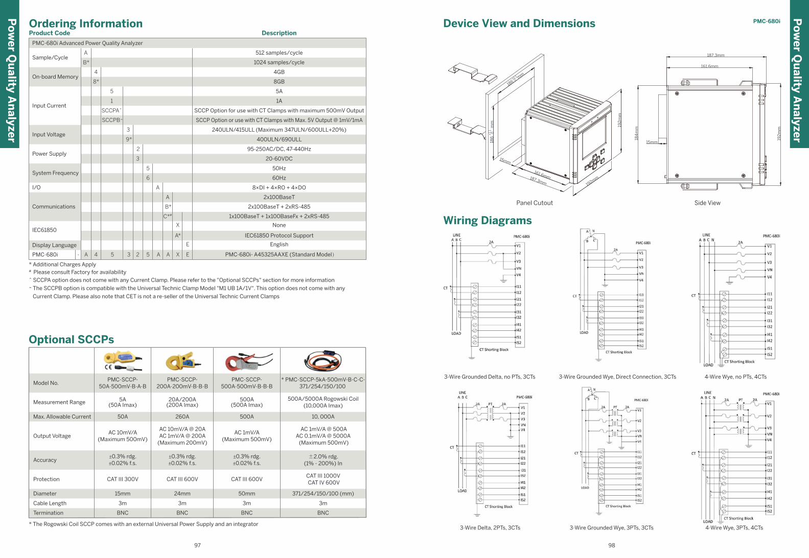
PMC-680i Advanced Power Quality Analyzer
* Additional Charges Apply# Please consult Factory for availability
^ SCCPA option does not come with any Current Clamp. Please refer to the "Optional SCCPs" section for more information
~ The SCCPB option is compatible with the Universal Technic Clamp Model "M1 UB 1A/1V". This option does not come with any
Current Clamp. Please also note that CET is not a re-seller of the Universal Technic Current Clamps
English
4GB
8GB
1024 samples/cycle
SCCP Option for use with CT Clamps with maximum 500mV Output
SCCP Option or use with CT Clamps with Max. 5V Output @ 1mV/1mA
240ULN/415ULL (Maximum 347ULN/600ULL+20%)
400ULN/690ULL
95-250AC/DC, 47-440Hz
20-60VDC
50Hz
60Hz
2x100BaseT + 2xRS-485
2x100BaseT
1x100BaseT + 1x100BaseFx + 2xRS-485
8×DI + 4×RO + 4×DO
5A
1A
Product Code DescriptionOrdering Information
None
IEC61850 Protocol Support
512 samples/cycleSample/Cycle
On-board Memory
Input Current
Input Voltage
Power Supply
System Frequency
I/O
Communications
Display Language
IEC61850
A
B*
4
8*
5
1
SCCPA^
SCCPB~
3
9*
2
3
5
6
B*
A
C*#
E
A- A A X4 5 3 2 5 PMC-680i- A45325AAXE (Standard Model)PMC-680i E
A
X
A*
* The Rogowski Coil SCCP comes with an external Universal Power Supply and an integrator
Optional SCCPs
BNC BNC
3m 3m
BNC
3m
15mm 24mm 50mm
CAT III 600V CAT III 600VCAT III 300V
±0.3% rdg.±0.02% f.s.
±0.3% rdg.±0.02% f.s.
±0.3% rdg.±0.02% f.s.
AC 10mV/A(Maximum 500mV)
AC 10mV/A @ 20AAC 1mV/A @ 200A
(Maximum 200mV)
AC 1mV/A(Maximum 500mV)
50A 260A 500A
5A(50A Imax)
20A/200A(200A Imax)
500A(500A Imax)
PMC-SCCP-50A-500mV-B-A-B
Model No.PMC-SCCP-
200A-200mV-B-B-BPMC-SCCP-
500A-500mV-B-B-B
Measurement Range
Max. Allowable Current
Output Voltage
Accuracy
Protection
Diameter
Cable Length
Termination BNC
3m
371/254/150/100 (mm)
CAT III 1000V CAT IV 600V
±2.0% rdg.(1% - 200%) In
AC 1mV/A @ 500AAC 0.1mV/A @ 5000A (Maximum 500mV)
10, 000A
500A/5000A Rogowski Coil(10,000A Imax)
* PMC-SCCP-5kA-500mV-B-C-C-371/254/150/100
Po
wer Q
uality A
nalyzer
PMC-680i
Po
wer Q
uality A
nalyzer
Wiring Diagrams
4-Wire Wye, no PTs, 4CTs3-Wire Grounded Delta, no PTs, 3CTs 3-Wire Grounded Wye, Direct Connection, 3CTs
3-Wire Delta, 2PTs, 3CTs 4-Wire Wye, 3PTs, 4CTs 3-Wire Grounded Wye, 3PTs, 3CTs
0+1.1
+1.
10
15mm
187.3mm
161.6mm
192mm
186 m
m
186
m
m
192
mm
15mm
192
mm
184
mm
161.6mm
187.3mm
Device View and Dimensions
Panel Cutout Side View
97 98

Main Features Metering PMC-690 performs basic measurements at 1-second
update rate and High-Speed measurements for event
detection at ½ cycle update rate
Basic Measurements (1-second update)
• 3-Phase U & I, Power, PF, U4, I4, Frequency and Phase
Angle, kWh, kvarh Import/Export/Net/Total and
kVAh Total
High-Speed Measurements (½ cycle update)
• 3-Phase Voltages and Currents, U4, I4, Power, PF,
Frequency
Data and Event RecordersLog Memory
• PMC-690 is equipped with a 16GB Removable SD
Card for non-volatile storage
Statistical Data Recorder (SDR)
• Recording of the Max., Min., Avg. and 95th percentile
of statistical measurements including U, I, Freq.,
Flicker, Harmonics & Unbalances
• Recording interval from 1 to 60 minutes
• 5 recorders (64 parameters/recorder)
• FIFO mode with configurable depth
• PQDIF file format, downloadable via the USB port
Max./Min. Recorder (MMR)
• 4 records (20 parameters/recorder) with Timestamp
• Logging of Max./Min. values for Real-time measure-
ments such as U, I, kW, kvar, kVA, PF, Freq., Unbal-
ance, K-Factor, THD
• Two log transfer modes: ○ Manual: Max./Min. Since Last Reset & Before Last
Reset○ Auto: Max./Min. of This Month & Last Month
Monitor Log
• 1024 FIFO entries time-stamped to ±1ms resolution
• Transients, Dips/Swells, Interruptions, Rapid Voltage
Changes, Inrush Current, Setpoint events
Device Log
• 1024 FIFO events time-stamped to ±1ms resolution
• Setup changes, System events, Setpoint events
CommunicationsEthernet Port
• 100BaseT TCP/IP Ethernet Ports with RJ45 connector
• Support Modbus TCP & IEC61850 Protocols
• Direct connection to PC with DiagSys for data transfer
• Simultaneous connections for 12xIEC61850 and
10xModbus TCP clientsSD Card
• 16GB Removable SD Card for easy data transfer to PCUSB Port
• Data transfer to USB storage device
• User friendly interface for transferring data/wave-
form through USB portDiagSys
• DiagSys is an integrated Power Quality Analysis
Software for reading and analyzing the data from
PMC-690
SetpointsPQ Setpoints
• Provides control output actions in response to
Transients, Dips/Swells, Rapid Voltage Changes,
Inrush Current and Harmonics
• Trigger SOE Log, RMS Recorder, WFR or DWRControl Setpoints
• 24 Control Setpoints and 16 High-Speed Setpoints
• Extensive monitoring sources
• Configurable thresholds and time delays
• Trigger SOE Log, RMS Recorder, WFR or DWR
√ 16GB Removable SD Card for Storage
√ IEC 62053-22 Class 0.5S
√ Class 0.1 accuracy for U & I Measurements
√ 5.7” Backlit Color TFT LCD Display
√ One Ethernet Port for On-line Communication
√ One USB Port for Data Backup
√ Low power consumption with 8 hours Battery Reserve
√ IEC 61000-4-30 Class A, EN 50160
Features Summary
Class (kWh)
Operating Temperature (ºC)
Dimensions (mm)
Display (Backlit)
True RMS Sampling Rate
Battery-backed Real-time Clock
General0.5S
-10 to 55
Color TFT640x480(Backlit)
√
252(W)x160(H)x59(D)
512
I/O-
-
-
-
-
-
-
-
Digital Input (DI)
Pulse Counter
Mechanical DigitalOutput (DO)/Solid StateOutput (SS)
Analog Input (AI),0/4-20mA
Analog Output (AO),0/4-20mA
kWh & kvarh Pulse Output (LED)
kWh & kvarh Pulse Output
IRIG-B (GPS)
Communications
Protocol
Ethernet
Modbus TCP, SNTP & IEC61850
RS-485 Port -
1
Web Server -
Power QualityTHD Voltage & Current
TOHD Voltage & Current
TEHD Voltage & Current
K-Factor
Individual Harmonics
Voltage/Current Unbalance
Waveform Capture on Screen
Waveform Recording
Dip Swell Detection
Transient Detection
√
√
2nd - 63rd
√
√
√
√
√
√
√
IEC 61000-4-30
2-150kHz Conducted Emission
Ed.2 Class A Compliant
-
MeasurementsULN per Phase & Avg.
ULL per Phase & Avg.
Current per Phase & Avg.
Neutral Current (Meas./Calc.)
Frequency
kW per Phase & Total
kvar per Phase & Total
kVA per Phase & Total
PF per Phase & Total
kWh Import/Export
kvarh Import/Export
kVAh Total
Demands & TOU
Maximum Demands
Setpoints
√
√
√
√
√
√
√
√
√
√
√
√
√
√
√
LogsSOE Log
PQ Log
Energy Log
Max./Min. Log
On-board Log Memory
1024 entries
√
16GB
1024 entries
√
Po
wer Q
uality A
nalyzer
PMC-690
PMC-690 Hand-Held Power Quality Analyzer
99 100
(Meas./Calc.)-Measured Value/Calculated Value
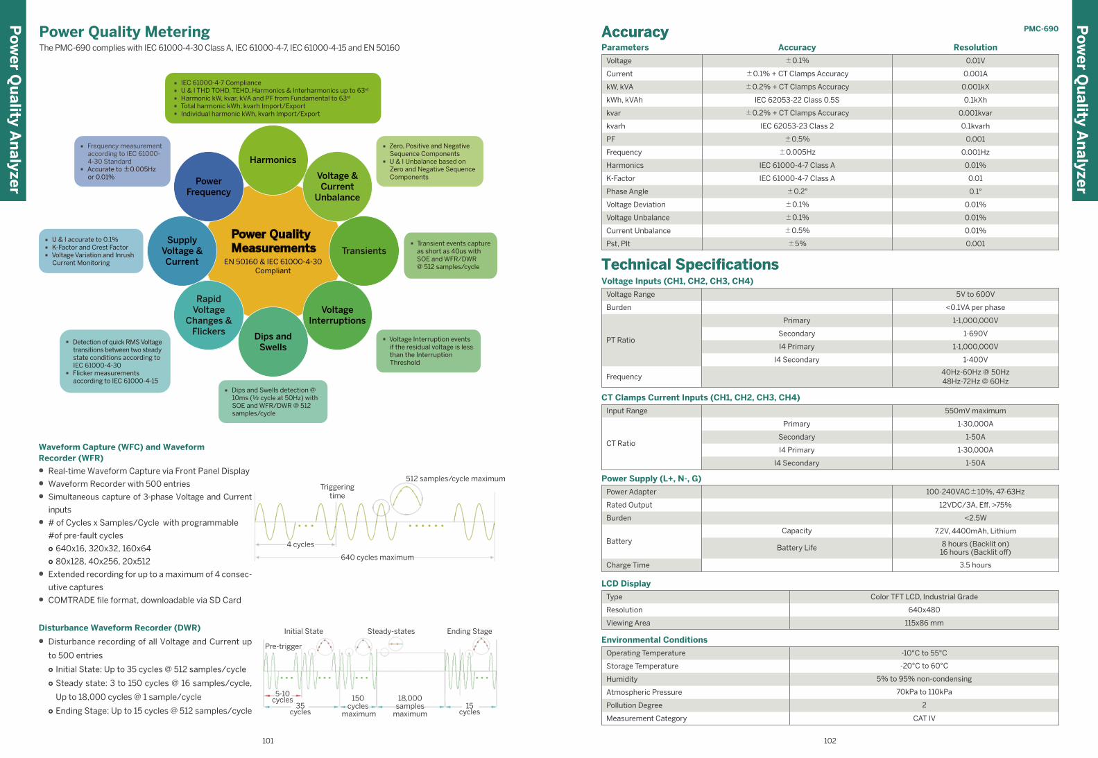
LCD Display
Type Color TFT LCD, Industrial Grade
Viewing Area 115x86 mm
Resolution 640x480
Environmental Conditions
Operating Temperature
Storage Temperature
Atmospheric Pressure 70kPa to 110kPa
Measurement Category
Humidity 5% to 95% non-condensing
Pollution Degree 2
Battery
Burden
Power Supply (L+, N-, G)
Power Adapter
Capacity
Rated Output
Burden
Battery
Charge Time
Battery Life
CT Clamps Current Inputs (CH1, CH2, CH3, CH4)
Input Range
CT Ratio
1-30,000A
1-50A
1-30,000A
1-50A
550mV maximum
Primary
Secondary
I4 Primary
I4 Secondary
8 hours (Backlit on)16 hours (Backlit off)
3.5 hours
100-240VAC±10%, 47-63Hz
<2.5W
7.2V, 4400mAh, Lithium
12VDC/3A, Eff. >75%
-10°C to 55°C
-20°C to 60°C
CAT IV
Parameters Accuracy Resolution
Voltage
Current
kW, kVA
kWh, kVAh
kvar
±0.1%
±0.2% + CT Clamps Accuracy
±0.1% + CT Clamps Accuracy
IEC 62053-22 Class 0.5S
±0.2% + CT Clamps Accuracy
0.01V
0.001A
0.001kX
0.1kXh
0.001kvar
kvarh IEC 62053-23 Class 2 0.1kvarh
PF ±0.5%
±0.005Hz
0.001
Frequency 0.001Hz
Harmonics IEC 61000-4-7 Class A 0.01%
K-Factor IEC 61000-4-7 Class A 0.01
Voltage Deviation 0.01%
Current Unbalance 0.01%
Phase Angle ±0.2° 0.1°
Voltage Unbalance ±0.1%
±0.5%
±0.1%
0.01%
Pst, Plt ±5% 0.001
AccuracyAccuracy
Voltage Inputs (CH1, CH2, CH3, CH4)
Voltage Range
Frequency
Primary
I4 Primary
Secondary
Technical SpecificationsTechnical Specifications
PT Ratio
Burden
I4 Secondary
5V to 600V
<0.1VA per phase
1-1,000,000V
1-1,000,000V
1-690V
1-400V
40Hz-60Hz @ 50Hz48Hz-72Hz @ 60Hz
PMC-690
Waveform Capture (WFC) and WaveformRecorder (WFR)
• Real-time Waveform Capture via Front Panel Display
• Waveform Recorder with 500 entries
• Simultaneous capture of 3-phase Voltage and Current
inputs
• # of Cycles x Samples/Cycle with programmable
#of pre-fault cycles○ 640x16, 320x32, 160x64○ 80x128, 40x256, 20x512
• Extended recording for up to a maximum of 4 consec-
utive captures
• COMTRADE file format, downloadable via SD Card
Disturbance Waveform Recorder (DWR)
• Disturbance recording of all Voltage and Current up
to 500 entries
○ Initial State: Up to 35 cycles @ 512 samples/cycle
○ Steady state: 3 to 150 cycles @ 16 samples/cycle,
Up to 18,000 cycles @ 1 sample/cycle
○ Ending Stage: Up to 15 cycles @ 512 samples/cycle
Pre-trigger
Initial State Steady-states Ending Stage
5-10cycles
35cycles
150cycles
maximum
18,000samples
maximum15
cycles
4 cycles
640 cycles maximum
Triggeringtime
512 samples/cycle maximum
Power Quality Metering The PMC-690 complies with IEC 61000-4-30 Class A, IEC 61000-4-7, IEC 61000-4-15 and EN 50160
Po
wer Q
uality A
nalyzer
Po
wer Q
uality A
nalyzer
102101
Power QualityMeasurements
EN 50160 & IEC 61000-4-30Compliant
Harmonics
Voltage &Current
Unbalance
Transients
Dips andSwells
RapidVoltage
Changes &Flickers
SupplyVoltage &Current
PowerFrequency
· IEC 61000-4-7 Compliance· U & I THD TOHD, TEHD, Harmonics & Interharmonics up to 63rd
· Harmonic kW, kvar, kVA and PF from Fundamental to 63rd
· Total harmonic kWh, kvarh Import/Export· Individual harmonic kWh, kvarh Import/Export
· Zero, Positive and NegativeSequence Components
· U & I Unbalance based onZero and Negative SequenceComponents
· Transient events capture as short as 40us with SOE and WFR/DWR @ 512 samples/cycle
· Voltage Interruption eventsif the residual voltage is lessthan the InterruptionThreshold
· Dips and Swells detection @10ms (½ cycle at 50Hz) withSOE and WFR/DWR @ 512samples/cycle
· Detection of quick RMS Voltagetransitions between two steadystate conditions according toIEC 61000-4-30
· Flicker measurementsaccording to IEC 61000-4-15
· U & I accurate to 0.1%· K-Factor and Crest Factor· Voltage Variation and Inrush
Current Monitoring
· Frequency measurementaccording to IEC 61000-4-30 Standard
· Accurate to ±0.005Hzor 0.01%
VoltageInterruptions
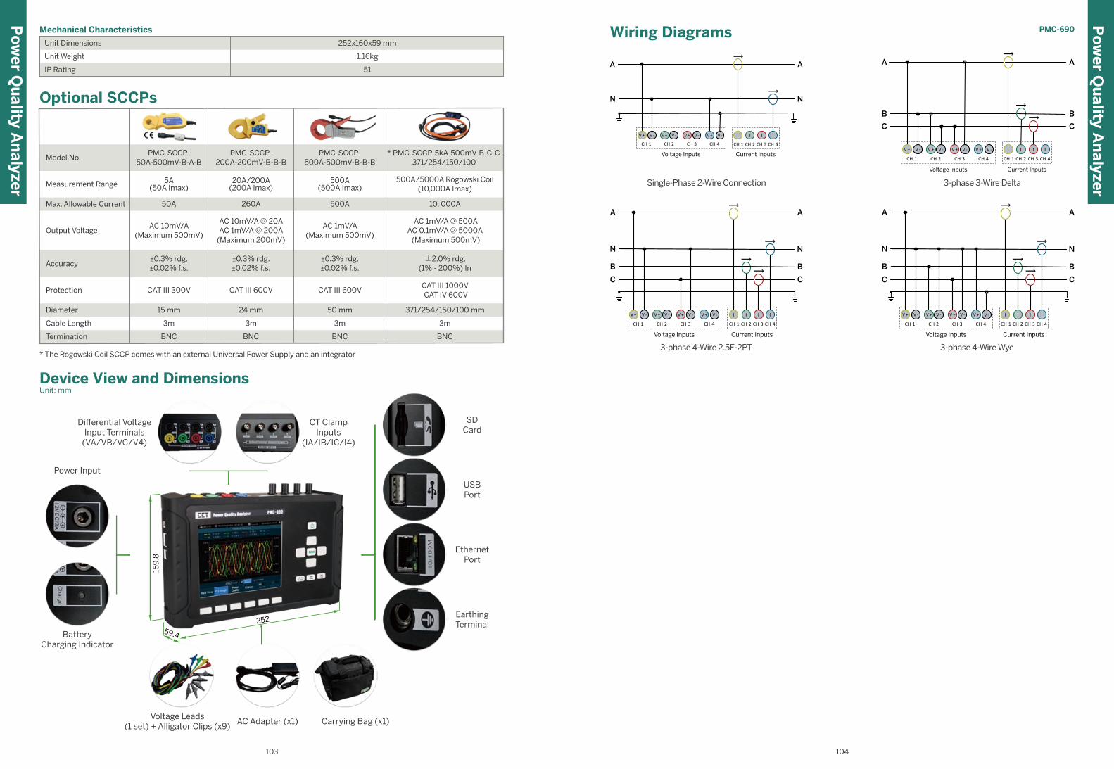
Single-Phase 2-Wire Connection
CH 1 CH 2 CH 3 CH 4
Voltage Inputs Current Inputs
I I IIV + V - V - V -V + V + V +
N
A A
N
CH 1 CH 2 CH 3 CH 4
V -
3-phase 3-Wire Delta
A
B
C
A
B
C
CH 1 CH 2 CH 3 CH 4CH 1 CH 2 CH 3 CH 4
Voltage Inputs Current Inputs
I I IV + V -V + V +V - V + V - IV -
3-phase 4-Wire Wye
A
B
C
CH 1 CH 2 CH 3 CH 4CH 1 CH 2 CH 3 CH 4
Voltage Inputs Current Inputs
A
NN
B
C
I I IIV + V - V - V - V -V + V + V +
3-phase 4-Wire 2.5E-2PT
A
B
C
CH 1 CH 2 CH 3 CH 4CH 1 CH 2 CH 3 CH 4
Voltage Inputs Current Inputs
A
NN
B
C
I I IIV + V - V - V - V -V + V + V +
Mechanical Characteristics
Unit Dimensions
Unit Weight
IP Rating 51
1.16kg
252x160x59 mm
* The Rogowski Coil SCCP comes with an external Universal Power Supply and an integrator
Optional SCCPs
BNC BNC
3m 3m
BNC
3m
15 mm 24 mm 50 mm
CAT III 600V CAT III 600VCAT III 300V
±0.3% rdg.±0.02% f.s.
±0.3% rdg.±0.02% f.s.
±0.3% rdg.±0.02% f.s.
AC 10mV/A(Maximum 500mV)
AC 10mV/A @ 20AAC 1mV/A @ 200A
(Maximum 200mV)
AC 1mV/A(Maximum 500mV)
50A 260A 500A
5A(50A Imax)
20A/200A(200A Imax)
500A(500A Imax)
PMC-SCCP-50A-500mV-B-A-B
Model No.PMC-SCCP-
200A-200mV-B-B-BPMC-SCCP-
500A-500mV-B-B-B
Measurement Range
Max. Allowable Current
Output Voltage
Accuracy
Protection
Diameter
Cable Length
Termination BNC
3m
371/254/150/100 mm
CAT III 1000V CAT IV 600V
±2.0% rdg.(1% - 200%) In
AC 1mV/A @ 500AAC 0.1mV/A @ 5000A (Maximum 500mV)
10, 000A
500A/5000A Rogowski Coil(10,000A Imax)
* PMC-SCCP-5kA-500mV-B-C-C-371/254/150/100
Po
wer Q
uality A
nalyzer
PMC-690
159
.8
252
59.4
Device View and DimensionsUnit: mm
Wiring Diagrams
Differential VoltageInput Terminals
(VA/VB/VC/V4)
CT ClampInputs
(IA/IB/IC/I4)
Power Input
BatteryCharging Indicator
SDCard
USBPort
EthernetPort
EarthingTerminal
Voltage Leads(1 set) + Alligator Clips (x9)
AC Adapter (x1) Carrying Bag (x1)
Po
wer Q
uality A
nalyzer
103 104

MeteringThe PMC-592 features high-accuracy measurements
for two Mains Inputs, each supporting 3 Voltage and
4 Current Inputs with the following measurements
Mains Inputs Measurements
• ULN and ULL per Phase and Average
• I per Phase and Average, measured Neutral Current
• kW, kvar, kVA, PF per Phase and Total
• Frequency
• Loading Factor per Phase and Average
• kWh Import/Export, kvarh Import/Export, kVAh Total
• Dual Tariff energy accumulation
Branch Circuits Measurements
Current Input provides the following measurements:
• 21, 42, 63 or 84 Branch Current Inputs. Each Branch
• I, kW, kvar, kVA, PF, Loading Factor, kWh, kvarh, kVAh
and Maximum Demand with Timestamp
Flexible Configuration
PMC-592 is designed to facilitate flexible installation in a
compact and high-density environment with program-
mable CT Ratio and Polarity, Phase or Line Reference
Voltage, 2-Ø and 3-Ø Sub-Meter Grouping, CT Strip
Installation Mode and Orientation as well as the follow-
ing features to make site installation a breeze.
• Flexible Configuration of CT Ratio and Polarity Facili-
tates Site Installation
• Support common panel arrangements such as
Single Panel Mode, Dual Panel Mode and 1-phase
3-Wire configuration
• A single PMC-592 can be used to monitor two PDUs,
each with one Mains and 42 Branch Circuits
• Any Branch Current Input can be paired with any
Phase or Line Voltage
• Flexible configuration for 2-Ø and 3-Ø Sub-Meter
Grouping to eliminate wiring mistakes at site that
would cause the complete breakdown of sub-meter
calculations due to rigid ordering for 2-Ø and 3-Ø
Sub-Meter wiring offered by other competitors
Data and Event RecordersData Recorder
• 1GB On-board log Memory
• 10 Recorders of 64 parameters each
• Real-time parameter recording for trend analysis
● Programmable Log Depth: 65535 maximum
Interval Energy Recorder
• Complete energy profiling of two Mains, 1-Ø, 2-Ø and
3-Ø Sub-Meters, Virtual Meters for Tariffs T1 and T2
• Mains: kWh Import/Export, kvarh Import/Export and
kVAh
• Sub-Meters and Virtual Meters: kWh Import, kvarh
Import and kVAh
• Programmable Interval at 5, 10, 15, 30 or 60 minute
Interval
• Fixed Log Depth at 10,000 entries, enough to record:
a. 1 month @ 5-minute b. 2 months @ 10-minute
c. 3 months @ 15-minute d. 6 months @ 30-minute
e. 12 months @ 60-minute
Max./Min. Recorder
• Mains: U, I, Frequency, kW, kvar, kVA, Loading Factor,
PF, Unbalance, THD, TOHD, TEHD
• RTD1 and RTD2
• 1-Ø Sub-Meters: I, kW, kvar, kVA, PF, Loading Factor
and I THD
• 2-Ø and 3-Ø Sub-Meters: I, kW, kvar, kVA, PF and
Loading Factor
• Max./Min. Timestamp for This Month & Last Month
(or Since Last Reset & Before Last Reset)
Waveform Recorder (WFR)
• Support up to 16 WFR Log entries
• Record V1-V3 and I1-I3 for both Mains-I and Mains-II
• Programmable resolutions (samples/cycle x # of
cycles) at 64x150, 64x75, 32x300, 32x150, 16x600
and 16x300
• Triggered by Dip/Swell and Interruption Setpoints
SOE Log & Alarm Monitoring
• 1000 events time-stamped to ±1ms resolution
• Alarm Summary At-A-Glance
• Global Alarm Output
• 4 Alarm Levels: HH, H, L and LL
• All alarms are recorded in the SOE Log
Inputs and OutputsThe PMC-592 provides Digital I/Os for status monitor-
ing, control, alarming as well as temperature monitoring.
These signals can also be integrated into BAS for build-
ing automation
Digital Inputs
• External status monitoring with programmable debounce
• 2 Channels, volt free dry contact, 24VDC internally wetted
Temperature Monitoring
• 2 Channels for PT100 sensor (sensor not included)
• Range from -40 to 200 °C
• Hot and Cold Aisle monitoring
Digital Outputs
● 2 Channels for external control and alarm
● 5A @ 250VAC/30VDC
● Facilitates Setpoint Control
Main FeaturesPMC-592 Multi-Circuit Power Monitor
Features Summary
I/O2
2DO
-
-
-
√
√
-
Digital Input (DI)
Pulse Counter
Mechanical DigitalOutput (DO)/Solid StateOutput (SS)
Analog Input (AI),0/4-20mA
Analog Output (AO),0/4-20mA
kWh & kvarh Pulse Output (LED)
kWh & kvarh Pulse Output
IRIG-B (GPS)
Communications
Protocol
Ethernet
Modbus RTU, Modbus TCP, HTTPSNMP, SNTP, SMTP
RS-485 Port 2
1
Web Server √
Power QualityTHD Voltage & Current
TOHD Voltage & Current
TEHD Voltage & Current
K-Factor
Individual Harmonics
Voltage/Current Unbalance
Waveform Capture on Screen
Waveform Recording
Dip Swell Detection
Transient Detection
√
√
2nd - 31st
-
√
√
√
√
√
-
IEC 61000-4-30
2-150kHz Conducted Emission
-
-
MeasurementsULN per Phase & Avg.
ULL per Phase & Avg.
Current per Phase & Avg.
Neutral Current (Meas./Calc.)
Frequency
kW per Phase & Total
kvar per Phase & Total
kVA per Phase & Total
PF per Phase & Total
kWh Import/Export
kvarh Import/Export
kVAh Total
Demands & TOU
Maximum Demands
Setpoints
√
√
√
√
√
√
√
√
√
√
√
√
√
√
√
LogsSOE Log
PQ Log
Energy Log
Max./Min. Log
On-board Log Memory
1000 entries
√
1GB
-
√
√ 1GB Non-Volatile Log Memory
√ IEC 62053-22 Class 0.5S (Mains)
√ IEC 62053-21 Class 1 (Branches)
√ Optional 7” Touch-Screen HMI
√ One Ethernet and dual RS-485 Ports
√ Monitor 2 Mains Circuits and up to 84 Branch Circuits
√ Support 1-Ø, 2-Ø and 3-Ø Sub-Metering
√ PQ Monitoring based on IEC 61000-4-30
Class (kWh)
Operating Temperature (ºC)
Dimensions (mm)
Display (Backlit)
True RMS Sampling Rate
Battery-backed Real-time Clock
General0.5S
-25 to 70
Optional Color TFT800x480(Backlit)
√
64
260.5(W)x154(H)x55.5(D)
PMC-592M
ulti C
ircuit M
on
itor
105 106
(Meas./Calc.)-Measured Value/Calculated Value
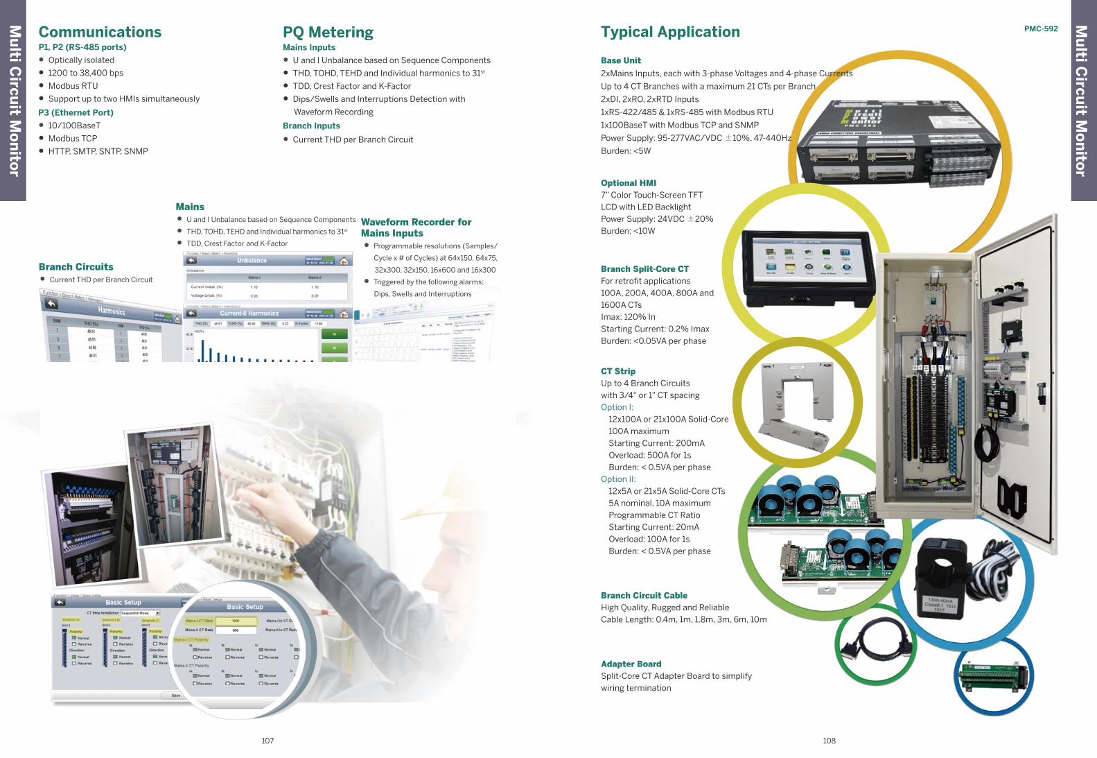
CommunicationsP1, P2 (RS-485 ports)
• Optically isolated
• 1200 to 38,400 bps
• Modbus RTU
• Support up to two HMIs simultaneously
P3 (Ethernet Port)
• 10/100BaseT
• Modbus TCP
• HTTP, SMTP, SNTP, SNMP
PQ MeteringMains Inputs
• U and I Unbalance based on Sequence Components
• THD, TOHD, TEHD and Individual harmonics to 31st
• TDD, Crest Factor and K-Factor
• Dips/Swells and Interruptions Detection with
Waveform Recording
Branch Inputs
• Current THD per Branch Circuit
Mains
• U and I Unbalance based on Sequence Components
• THD, TOHD, TEHD and Individual harmonics to 31st
• TDD, Crest Factor and K-Factor
Waveform Recorder forMains Inputs
• Programmable resolutions (Samples/
Cycle x # of Cycles) at 64x150, 64x75,
32x300, 32x150, 16x600 and 16x300
• Triggered by the following alarms:
Dips, Swells and Interruptions
Branch Circuits
• Current THD per Branch Circuit
Optional HMI7” Color Touch-Screen TFTLCD with LED BacklightPower Supply: 24VDC ±20%Burden: <10W
Branch Split-Core CTFor retrofit applications100A, 200A, 400A, 800A and 1600A CTs Imax: 120% InStarting Current: 0.2% Imax Burden: <0.05VA per phase
Adapter BoardSplit-Core CT Adapter Board to simplify wiring termination
Branch Circuit CableHigh Quality, Rugged and ReliableCable Length: 0.4m, 1m, 1.8m, 3m, 6m, 10m
CT StripUp to 4 Branch Circuitswith 3/4" or 1" CT spacingOption I: 12x100A or 21x100A Solid-Core 100A maximum Starting Current: 200mA Overload: 500A for 1s Burden: < 0.5VA per phaseOption II: 12x5A or 21x5A Solid-Core CTs 5A nominal, 10A maximum Programmable CT Ratio Starting Current: 20mA Overload: 100A for 1s Burden: < 0.5VA per phase
Typical Application
Base Unit
2xMains Inputs, each with 3-phase Voltages and 4-phase Currents
Up to 4 CT Branches with a maximum 21 CTs per Branch
2xDI, 2xRO, 2xRTD Inputs
1xRS-422/485 & 1xRS-485 with Modbus RTU
1x100BaseT with Modbus TCP and SNMP
Power Supply: 95-277VAC/VDC ±10%, 47-440Hz
Burden: <5W
PMC-592M
ulti C
ircuit M
on
itor
Mu
lti Circu
it Mo
nito
r
107 108
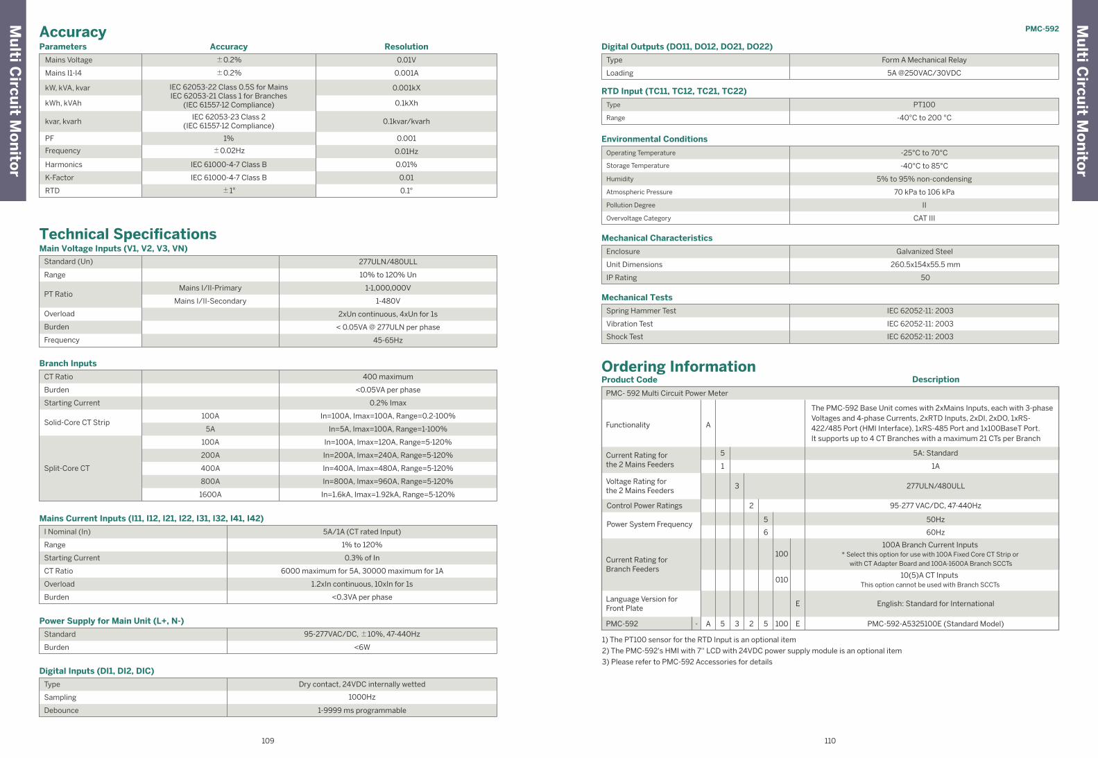
Mechanical Tests
Spring Hammer Test
Vibration Test
IEC 62052-11: 2003
IEC 62052-11: 2003
IEC 62052-11: 2003Shock Test
Enclosure
IP Rating
Mechanical Characteristics
Unit Dimensions
Enclosure
IP Rating
Galvanized Steel
260.5x154x55.5 mm
50
Humidity
Environmental Conditions
Operating Temperature
Storage Temperature
Humidity
Atmospheric Pressure
Pollution Degree
-25°C to 70°C
-40°C to 85°C
5% to 95% non-condensing
70 kPa to 106 kPa
II
Overvoltage Category CAT III
Enclosure
RTD Input (TC11, TC12, TC21, TC22)
Range
Type PT100
-40°C to 200 °C
Enclosure
Digital Outputs (DO11, DO12, DO21, DO22)
Loading
Type Form A Mechanical Relay
5A @250VAC/30VDC
Ordering InformationProduct Code
PMC- 592 Multi Circuit Power Meter
Functionality A
A 5 3 2 5 100 E
1
Current Rating forthe 2 Mains Feeders
Description
3
2
5
6
100
010
E
Voltage Rating forthe 2 Mains Feeders
Control Power Ratings
Power System Frequency
Language Version forFront Plate
PMC-592
1) The PT100 sensor for the RTD Input is an optional item
2) The PMC-592's HMI with 7'' LCD with 24VDC power supply module is an optional item
3) Please refer to PMC-592 Accessories for details
-
5
The PMC-592 Base Unit comes with 2xMains Inputs, each with 3-phaseVoltages and 4-phase Currents, 2xRTD Inputs, 2xDI, 2xDO, 1xRS-422/485 Port (HMI Interface), 1xRS-485 Port and 1x100BaseT Port. It supports up to 4 CT Branches with a maximum 21 CTs per Branch
1A
277ULN/480ULL
95-277 VAC/DC, 47-440Hz
50Hz
60Hz
10(5)A CT Inputs This option cannot be used with Branch SCCTs
100A Branch Current Inputs* Select this option for use with 100A Fixed Core CT Strip or
with CT Adapter Board and 100A-1600A Branch SCCTs
English: Standard for International
PMC-592-A5325100E (Standard Model)
5A: Standard
Current Rating forBranch Feeders
Accuracy
Technical Specifications
Parameters Accuracy Resolution
Mains Voltage
Mains I1-I4
±0.2%
±0.2%
IEC 62053-22 Class 0.5S for MainsIEC 62053-21 Class 1 for Branches
(IEC 61557-12 Compliance)
0.01V
0.001A
0.001kX
0.001
0.01Hz
0.01%
0.01
kvar, kvarh
PF
Frequency
Harmonics
K-Factor
RTD
1%
±0.02Hz
IEC 61000-4-7 Class B
IEC 61000-4-7 Class B
±1° 0.1°
Enclosure
IP Rating
Digital Inputs (DI1, DI2, DIC)
Sampling
Type
Debounce
Dry contact, 24VDC internally wetted
1000Hz
1-9999 ms programmable
Enclosure
Power Supply for Main Unit (L+, N-)
Burden
Standard 95-277VAC/DC, ±10%, 47-440Hz
<6W
Humidity
Mains Current Inputs (I11, I12, I21, I22, I31, I32, I41, I42)
I Nominal (In)
Range
Starting Current
CT Ratio
Overload
5A/1A (CT rated Input)
1% to 120%
0.3% of In
6000 maximum for 5A, 30000 maximum for 1A
1.2xIn continuous, 10xIn for 1s
Burden <0.3VA per phase
Humidity
Branch Inputs
CT Ratio
Burden
Starting Current
Solid-Core CT Strip 100A
Split-Core CT
<0.05VA per phase
0.2% Imax
In=100A, Imax=100A, Range=0.2-100%
Humidity
Main Voltage Inputs (V1, V2, V3, VN)
Standard (Un)
Range
PT Ratio
Overload
Burden
277ULN/480ULL
10% to 120% Un
2xUn continuous, 4xUn for 1s
Frequency 45-65Hz
Mains I/II-Primary
Mains I/II-Secondary
1-1,000,000V
1-480V
< 0.05VA @ 277ULN per phase
5A In=5A, Imax=100A, Range=1-100%
100A
200A
400A
800A
1600A
In=100A, Imax=120A, Range=5-120%
In=200A, Imax=240A, Range=5-120%
In=400A, Imax=480A, Range=5-120%
In=800A, Imax=960A, Range=5-120%
In=1.6kA, Imax=1.92kA, Range=5-120%
400 maximum
kW, kVA, kvar
kWh, kVAh 0.1kXh
IEC 62053-23 Class 2(IEC 61557-12 Compliance)
0.1kvar/kvarh
PMC-592
Mu
lti Circu
it Mo
nito
r
Mu
lti Circu
it Mo
nito
r
109 110
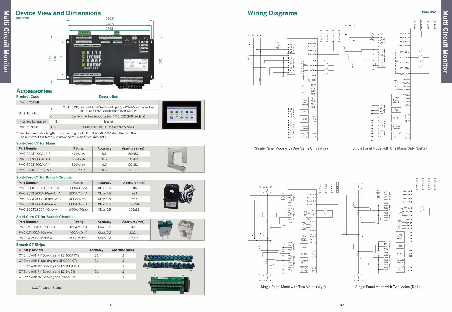
Single Panel Mode with One Mains Only (Wye) Single Panel Mode with One Mains Only (Delta)
Single Panel Mode with Two Mains (Wye) Single Panel Mode with Two Mains (Delta)
Split-Core CT for Branch Circuits
Branch CT Strips
PMC-SCCT-200A-40mA-24-A
PMC-SCCT-400A-40mA-35-A
PMC-SCCT-800A-40mA-A
PMC-SCCT-1600A-40mA-A
PMC-SCCT-100A-40mA-16-A
200A/40mA
400A/40mA
800A/40mA
1600A/40mA
100A/40mA
Class 0.5
Class 0.5
Class 0.5
Class 0.5
Class 0.5
Ø24
Ø35
80x50
129x55
Ø16
Rating Accuracy Aperture (mm)
PMC-SCCT-600A-1A-A
PMC-SCCT-800A-1A-A
PMC-SCCT-1000A-1A-A
PMC-SCCT-400A-1A-A
600A/1A
800A/1A
1000A/1A
400A/1A
0.5
0.5
0.5
0.5
50×80
50×80
80×120
50×80
Split-Core CT for MainsRatingPart Number
Part Number
Accuracy Aperture (mm)
PMC-CT-400A-40mA-A
PMC-CT-800A-40mA-A
PMC-CT-100A-40mA-12-A
400A/40mA
800A/40mA
100A/40mA
Class 0.2
Class 0.2
Class 0.2
31x24
103x33
Ø12
Solid-Core CT for Branch Circuits Rating Accuracy Aperture (mm)
Accessories
* The standard cable length for connecting the HMI to the PMC-592 Main Unit is 3.0m Please contact the factory in advance for special requirements
Product Code
PMC-592-HMI
7'' TFT LCD, 800x480, 1xRS-422/485 port, a RS-422 cable and an external 24VDC Switching Power Supply
Basic Function
Description
A
Same as 'A' but supports two PMC-592 (168 feeders)C
EnglishInterface Language E
PMC-592HMI PMC-592-HMI-AE (Standard Model)A- E
CT Strip with ¾" Spacing and 21×100A CTs
CT Strip with ¾" Spacing and 12×5A CTs
CT Strip with ¾" Spacing and 21×5A CTs
SCCT Adapter Board
CT Strip with 1" Spacing and 21×100A CTs
CT Strip with ¾" Spacing and 12×100A CTs
Accuracy Aperture (mm)
0.1
0.1
0.1
0.1
0.1
11
11
11
11
11
- -
Part Number
CT Strip Models
Device View and DimensionsUnit: mm
236.5
154
130
110
170
248.5
260.5
Wiring Diagrams
FU
FU
FU
I11I12I21I22I31I32I41I42
V1V2V3VN
I11I12I21I22I31I32
I42
Branch A
Branch B
Branch C
Branch D
CT Strip A
CT Strip B
CT Strip C
CT Strip D
DO11
DO12
DO21
DO22
L/+
N/-
Temp.SensorModule
TC11
TC12
TC21
TC22
10/100MEthernet
*
A B C
*
*
I41
Mains-I C
urrentV
oltage-II
Mains-II C
urrent
V1V2V3VN
Voltag
e-I
RS-485
D+
D-SH
DB9
DI4
DIC24V
DI3
DI2
DI1
FU
FU
FU
I11I12I21I22I31I32I41I42
V1V2V3VN
I11I12I21I22I31I32
I42
Branch A
Branch B
Branch C
Branch D
CT Strip A
CT Strip B
CT Strip C
CT Strip D
DI1
DI2
DIC24V
DO11
DO12
DO21
DO22
L/+
N/-
Temp.SensorModule
TC11
TC12
TC21
TC22
10/100MEthernet
*A B C
*
*
*A B C
*
*
I41
Mains-I C
urrentV
oltage-II
Mains-II C
urrent
V1V2V3VN
Voltag
e-I
RS-485
D+
D-SH
DB9
FU
FU
FU
Voltage-I
V1V2V3VN
I11I12I21I22I31I32I41I42
Mains-I C
urrentV
oltage-II
V1V2V3VN
I11I12I21I22I31I32I41I42
Mains-II C
urrent
Branch A
Branch B
Branch C
Branch D
CT Strip A
CT Strip
B
CT Strip C
CT Strip D
DO11
DO12DO21
DO22
L/+
N/ -
Temp.SensorModule
TC11
TC12TC21
TC22
10/ 100 MEthernet
*A B C N
*
*
*
RS-485
D+
D-SH
DB9
DI4
DIC24V
DI3
DI2
DI1
FU
FU
FU
I11I12I21I22I31I32I41I42
V1V2V3VN
I11I12I21I22I31I32
I42
Branch A
Branch B
Branch C
Branch D
CT Strip A
CT Strip B
CT Strip C
CT Strip D
DI1
DI2
DIC24V
DO11
DO12
DO21
DO22
L/+
N/-
Temp.SensorModule
TC11
TC12
TC21
TC22
10/100MEthernet
*A B C N
*
*
*
*A B C N
*
*
*I41
Mains-I C
urrentV
oltage-II
Mains-II C
urrent
V1V2V3VN
Voltag
e-I
RS-485
D+
D-SH
DB9
PMC-592M
ulti C
ircuit M
on
itor
Mu
lti Circu
it Mo
nito
r
111 112
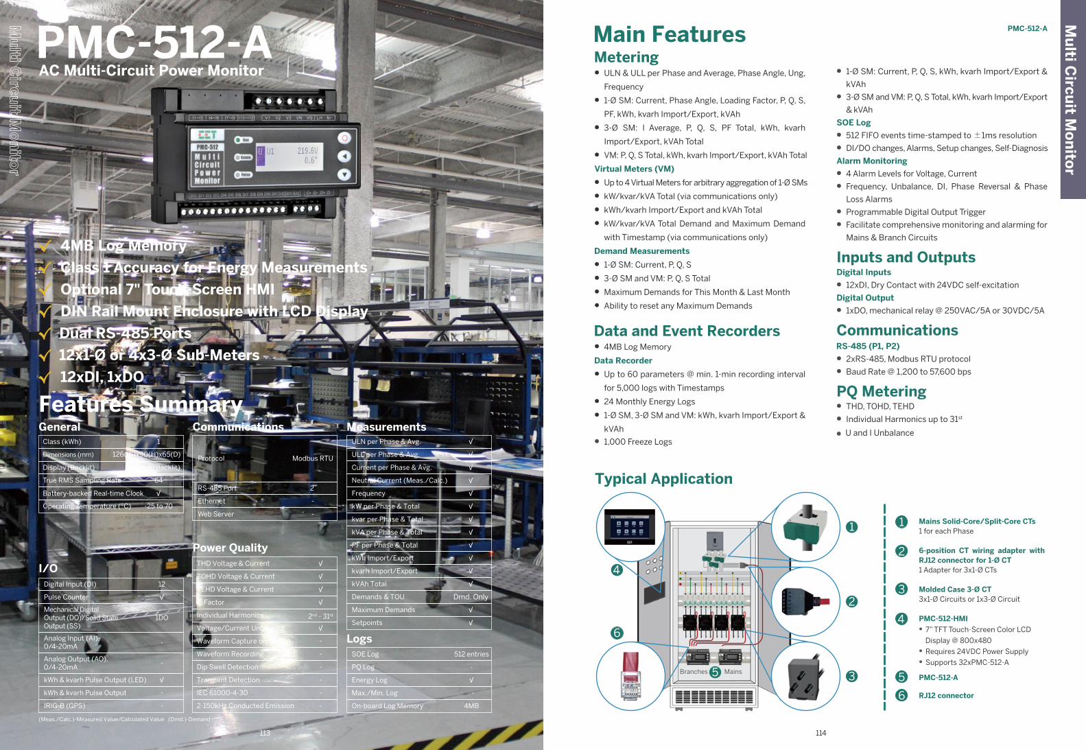
Main FeaturesMetering• ULN & ULL per Phase and Average, Phase Angle, Ung,
Frequency
• 1-Ø SM: Current, Phase Angle, Loading Factor, P, Q, S,
PF, kWh, kvarh Import/Export, kVAh
• 3-Ø SM: I Average, P, Q, S, PF Total, kWh, kvarh
Import/Export, kVAh Total
• VM: P, Q, S Total, kWh, kvarh Import/Export, kVAh Total
Virtual Meters (VM)
• Up to 4 Virtual Meters for arbitrary aggregation of 1-Ø SMs
• kW/kvar/kVA Total (via communications only)
• kWh/kvarh Import/Export and kVAh Total
• kW/kvar/kVA Total Demand and Maximum Demand
with Timestamp (via communications only)
Demand Measurements
• 1-Ø SM: Current, P, Q, S
• 3-Ø SM and VM: P, Q, S Total
• Maximum Demands for This Month & Last Month
• Ability to reset any Maximum Demands
Data and Event Recorders• 4MB Log Memory
Data Recorder
• Up to 60 parameters @ min. 1-min recording interval
for 5,000 logs with Timestamps
• 24 Monthly Energy Logs
• 1-Ø SM, 3-Ø SM and VM: kWh, kvarh Import/Export &
kVAh
• 1,000 Freeze Logs
• 1-Ø SM: Current, P, Q, S, kWh, kvarh Import/Export &
kVAh
• 3-Ø SM and VM: P, Q, S Total, kWh, kvarh Import/Export
& kVAh
SOE Log
• 512 FIFO events time-stamped to ±1ms resolution
• DI/DO changes, Alarms, Setup changes, Self-Diagnosis
Alarm Monitoring
• 4 Alarm Levels for Voltage, Current
• Frequency, Unbalance, DI, Phase Reversal & Phase
Loss Alarms
• Programmable Digital Output Trigger
• Facilitate comprehensive monitoring and alarming for
Mains & Branch Circuits
Inputs and OutputsDigital Inputs
• 12xDI, Dry Contact with 24VDC self-excitation
Digital Output
• 1xDO, mechanical relay @ 250VAC/5A or 30VDC/5A
CommunicationsRS-485 (P1, P2)
• 2xRS-485, Modbus RTU protocol
• Baud Rate @ 1,200 to 57,600 bps
PQ Metering• THD, TOHD, TEHD
• Individual Harmonics up to 31st
● U and I Unbalance
PMC-512-AAC Multi-Circuit Power Monitor
Features Summary
Class (kWh)
Operating Temperature (ºC)
Dimensions (mm)
Display (Backlit)
True RMS Sampling Rate
Battery-backed Real-time Clock
General1
-25 to 70
B&W(Backlit)
√
126(W)x90(H)x65(D)
64
I/O12
1DO
-
-
-
√
√
-
Digital Input (DI)
Pulse Counter
Mechanical DigitalOutput (DO)/Solid StateOutput (SS)
Analog Input (AI),0/4-20mA
Analog Output (AO),0/4-20mA
kWh & kvarh Pulse Output (LED)
kWh & kvarh Pulse Output
IRIG-B (GPS)
Communications
Protocol
Ethernet
Modbus RTU
RS-485 Port 2
-
Web Server -
Power QualityTHD Voltage & Current
TOHD Voltage & Current
TEHD Voltage & Current
K-Factor
Individual Harmonics
Voltage/Current Unbalance
Waveform Capture on Screen
Waveform Recording
Dip Swell Detection
Transient Detection
√
√
2nd - 31st
-
-
√
√
√
-
-
IEC 61000-4-30
2-150kHz Conducted Emission
-
-
MeasurementsULN per Phase & Avg.
ULL per Phase & Avg.
Current per Phase & Avg.
Neutral Current (Meas./Calc.)
Frequency
kW per Phase & Total
kvar per Phase & Total
kVA per Phase & Total
PF per Phase & Total
kWh Import/Export
kvarh Import/Export
kVAh Total
Demands & TOU
Maximum Demands
Setpoints
√
√
√
√
√
√
Dmd. Only
√
√
√
√
√
√
√
√
LogsSOE Log
PQ Log
Energy Log
Max./Min. Log
On-board Log Memory
512 entries
√
4MB
-
-
√ 4MB Log Memory
√ Class 1 Accuracy for Energy Measurements
√ Optional 7" Touch-Screen HMI
√ DIN Rail Mount Enclosure with LCD Display
√ Dual RS-485 Ports
√ 12x1-Ø or 4x3-Ø Sub-Meters
√ 12xDI, 1xDO
Typical Application
1
2
3
5
6
4
Mains Solid-Core/Split-Core CTs1 for each Phase
6-position CT wiring adapter with RJ12 connector for 1-Ø CT1 Adapter for 3x1-Ø CTs
Molded Case 3-Ø CT 3x1-Ø Circuits or 1x3-Ø Circuit
PMC-512-HMI● 7” TFT Touch-Screen Color LCD
Display @ 800x480● Requires 24VDC Power Supply● Supports 32xPMC-512-A
PMC-512-A
RJ12 connector
1
2
35
4
6
Branches Mains
PMC-512-AM
ulti C
ircuit M
on
itor
114113
(Meas./Calc.)-Measured Value/Calculated Value (Dmd.)-Demand
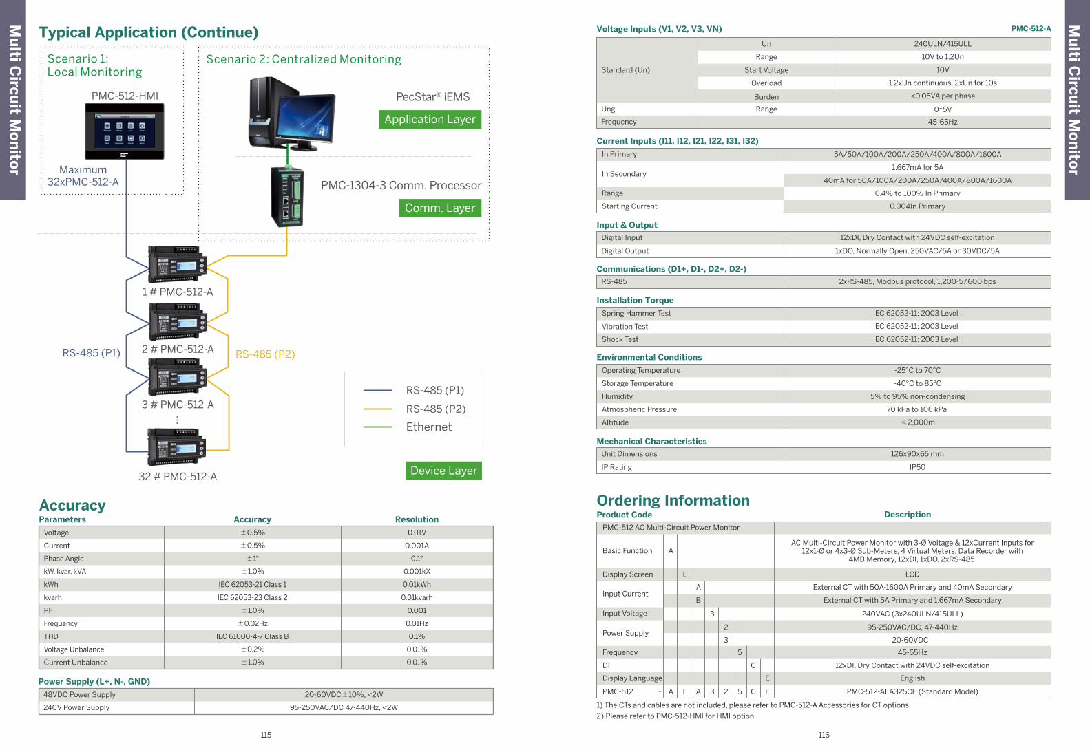
Typical Application (Continue)
Power Supply (L+, N-, GND)
48VDC Power Supply
240V Power Supply
20-60VDC±10%, <2W
95-250VAC/DC 47-440Hz, <2W
Accuracy
Installation Torque
Spring Hammer Test
Vibration Test
Shock Test
IEC 62052-11: 2003 Level I
IEC 62052-11: 2003 Level I
IEC 62052-11: 2003 Level I
Communications (D1+, D1-, D2+, D2-)
RS-485 2xRS-485, Modbus protocol, 1,200-57,600 bps
Operating Temperature
Storage Temperature
Humidity
Atmospheric Pressure
Altitude
-40°C to 85°C
5% to 95% non-condensing
70 kPa to 106 kPa
Environmental Conditions
-25°C to 70°C
≤2,000m
In Primary
In Secondary
Range
Starting Current
1.667mA for 5A
40mA for 50A/100A/200A/250A/400A/800A/1600A
0.4% to 100% In Primary
Current Inputs (I11, I12, I21, I22, I31, I32)
5A/50A/100A/200A/250A/400A/800A/1600A
0.004In Primary
1) The CTs and cables are not included, please refer to PMC-512-A Accessories for CT options
2) Please refer to PMC-512-HMI for HMI option
Ordering InformationProduct Code
PMC-512 AC Multi-Circuit Power Monitor
AC Multi-Circuit Power Monitor with 3-Ø Voltage & 12xCurrent Inputs for12x1-Ø or 4x3-Ø Sub-Meters, 4 Virtual Meters, Data Recorder with
4MB Memory, 12xDI, 1xDO, 2xRS-485 Basic Function
Frequency
DI
PMC-512
L
L
A
A-
A
A 5 C E
3
3 2
20-60VDC
PMC-512-ALA325CE (Standard Model)
External CT with 50A-1600A Primary and 40mA Secondary
LCDDisplay Screen
Input Current
Input Voltage
Power Supply
Description
External CT with 5A Primary and 1.667mA SecondaryB
240VAC (3x240ULN/415ULL)3
2 95-250VAC/DC, 47-440Hz
45-65Hz5
C 12xDI, Dry Contact with 24VDC self-excitation
E EnglishDisplay Language
Voltage Inputs (V1, V2, V3, VN)
Input & Output
Digital Input 12xDI, Dry Contact with 24VDC self-excitation
Digital Output 1xDO, Normally Open, 250VAC/5A or 30VDC/5A
Mechanical Characteristics
Unit Dimensions 126x90x65 mm
IP Rating IP50
240ULN/415ULL
10V to 1.2Un
<0.05VA per phase
Frequency 45-65Hz
Start Voltage
Overload
Burden
Range
Un
Range
10V
1.2xUn continuous, 2xUn for 10s
0~5VUng
Standard (Un)
PMC-512-A
Mu
lti Circu
it Mo
nito
r
Mu
lti Circu
it Mo
nito
r
115 116
Parameters Accuracy Resolution
Voltage
Current
Phase Angle
kW, kvar, kVA
kWh
±0.5%
±1°
±1.0%
IEC 62053-21 Class 1
0.001A
0.1°
0.001kX
0.01kWh
kvarh IEC 62053-23 Class 2 0.01kvarh
PF ±1.0% 0.001
Frequency ±0.02Hz 0.01Hz
THD
Voltage Unbalance
Current Unbalance
IEC 61000-4-7 Class B
±0.2%
±1.0%
0.1%
0.01%
0.01%
±0.5% 0.01V
PMC-1304-3 Comm. Processor
1 # PMC-512-A
2 # PMC-512-A
3 # PMC-512-A
32 # PMC-512-A
…
PecStar® iEMS
Comm. Layer
Device Layer
Application Layer
RS-485 (P2)RS-485 (P1)
RS-485 (P1)
RS-485 (P2)
Ethernet
PMC-512-HMI
Scenario 1:Local Monitoring
Scenario 2: Centralized Monitoring
Maximum32xPMC-512-A
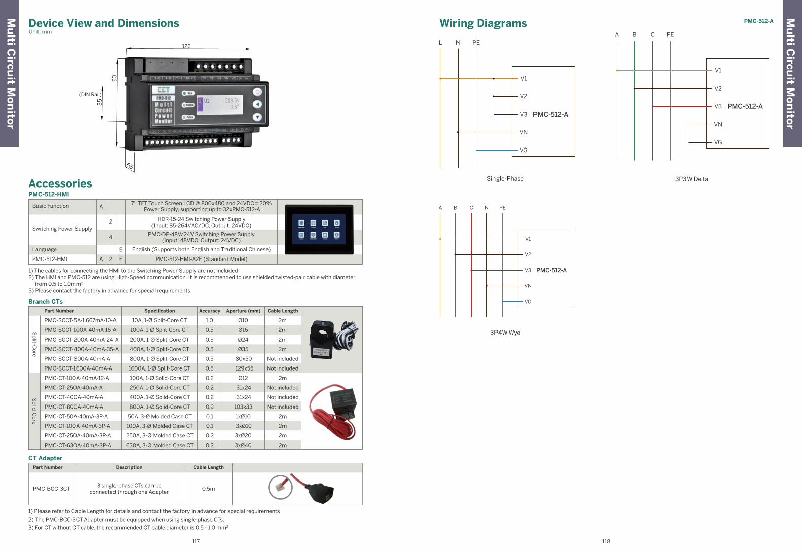
Device View and DimensionsUnit: mm
Wiring Diagrams
Single-Phase
L N PE
V1
V2
V3 PMC-512-A
VN
VG
A B C PE
V1
V2
V3 PMC-512-A
VN
VG
3P3W Delta
A B C N PE
V1
V2
V3 PMC-512-A
VN
VG
3P4W Wye
(DIN Rail)
126
90
35
65
Description Cable Length
1) Please refer to Cable Length for details and contact the factory in advance for special requirements
2) The PMC-BCC-3CT Adapter must be equipped when using single-phase CTs.
3) For CT without CT cable, the recommended CT cable diameter is 0.5 - 1.0 mm2
PMC-BCC-3CT3 single-phase CTs can be
connected through one Adapter0.5m
CT Adapter
Branch CTs
Part Number
PMC-512-HMI
Accessories
1) The cables for connecting the HMI to the Switching Power Supply are not included2) The HMI and PMC-512 are using High-Speed communication. It is recommended to use shielded twisted-pair cable with diameter from 0.5 to 1.0mm²3) Please contact the factory in advance for special requirements
PMC-512-HMI
7'' TFT Touch Screen LCD @ 800x480 and 24VDC±20% Power Supply, supporting up to 32xPMC-512-A
Basic Function
2
4
A
English (Supports both English and Traditional Chinese)
PMC-DP-48V/24V Switching Power Supply(Input: 48VDC, Output: 24VDC)
HDR-15-24 Switching Power Supply(Input: 85-264VAC/DC, Output: 24VDC)
Switching Power Supply
Language
PMC-512-HMI-A2E (Standard Model)2A E
E
PMC-CT-250A-40mA-3P-A
PMC-CT-630A-40mA-3P-A
PMC-CT-100A-40mA-3P-A
250A, 3-Ø Molded Case CT
630A, 3-Ø Molded Case CT
100A, 3-Ø Molded Case CT
0.2
0.2
0.1
3xØ20
3xØ40
3xØ10
2m
2m
2m
PMC-SCCT-200A-40mA-24-A
PMC-SCCT-400A-40mA-35-A
PMC-SCCT-100A-40mA-16-A
PMC-SCCT-1600A-40mA-A
PMC-SCCT-800A-40mA-A
200A, 1-Ø Split-Core CT
400A, 1-Ø Split-Core CT
100A, 1-Ø Split-Core CT
1600A, 1-Ø Split-Core CT
800A, 1-Ø Split-Core CT
0.5
0.5
0.5
0.5
0.5
Ø35
Ø24
Ø16
129x55
80x50
2m
2m
2m
PMC-SCCT-5A-1.667mA-10-A 10A, 1-Ø Split-Core CT 1.0 Ø10 2m
Not included
Not included
PMC-CT-100A-40mA-12-A
PMC-CT-250A-40mA-A
PMC-CT-400A-40mA-A
100A, 1-Ø Solid-Core CT
250A, 1-Ø Solid-Core CT
400A, 1-Ø Solid-Core CT
0.2
0.2
0.2
Ø12
31x24
31x24
2m
PMC-CT-800A-40mA-A 800A, 1-Ø Solid-Core CT 0.2 103x33 Not included
PMC-CT-50A-40mA-3P-A 50A, 3-Ø Molded Case CT 0.1 1xØ10 2m
Not included
Not included
SpecificationPart Number Accuracy Aperture (mm) Cable Length
Sp
lit-Co
reS
olid
-Co
re
PMC-512-A
Mu
lti Circu
it Mo
nito
r
Mu
lti Circu
it Mo
nito
r
117 118

Device View and DimensionsUnit: mm
PMC-SCCP-200A-200mV-B-B-B
PMC-SCCP-50A-500mV-B-A-B
BNCconnector
Ferrite core
Cable
Lock knob
Jaws
Currentdirectionindicator
40.04±1
120
.83±
1
14.6±0.5
48.25±1
20±0.5
ø15±0.5
PMC-SCCP-500A-500mV-B-B-B
Jaws
BNCconnector
Ferrite core
Cable
Currentdirectionindicator
100.37±130±0.5
35.23±0.5
215
.22±
1
ø51±1
PMC-SCCP-5kA-500mV-B-C-C
S2.1
S2.1
AC adapterconnectionterminal
Switch
POWER LED
Coupling
Flexible loop
BNC-BNC Connector
Output cable
Circuit box(Battery cover [on back])
BNCconnector
Connectedinstrument
Current Transformer and Current ProbePMC-CT, SCCT & SCCP
√ Designed for CET’s Meters and Analyzers
√ Wide Application Range from 5A to 5000A
√ CT & SCCT: RoHS Compliance
√ SCCP: EN 61010-2-032: 2012 Safety Compliance
Caution● Avoid using the instrument if it has been exposed to rain or
moisture, or if your hands are wet.
● To avoid unexpected injury when performing measurements on live conductors, always put on insulated gloves, boots, safety helmet and other personal protective equipment.
● The instrument should only be connected to the secondary side of a breaker, which is designed to prevent accidents in the event of a short circuit. The product should never be used on the primary side of a breaker because un-restricted current could cause serious accidents if a short circuit occurs.
● To avoid short circuits and potentially life threatening hazards, never attach the instrument to a circuit that operates at a voltage exceeding its rated value.
● Never use the instrument to measure currents that are higher than the rated maximum limit for an extended period of time or it may cause permanent damage to the instrument.
● Do not use the instrument around non-insulated conductors or if the insulation has been damaged.
● The secondary output should be connected to the receiving circuit and should not be left open-circuited before connecting the instrument to a live conductor.
● Dropping the instrument or subjecting it to mechanical shock could cause damage to the contact mechanism and adversely affect its measurement accuracy.
Maintenance● Always keep the clamp closed when it’s not being used to prevent dust or exterior objects from accumulating
on the contact surfaces inside the clamp jaw for best electrical and mechanical performance.
● Bending, pinching or pulling on the cable could cause permanent damage to the cable’s insulation properties.
● Clean the surface of the instrument periodically with a soft cloth damped with water or mild detergent.
● Do not use abrasive cleaner or solvent such as benzene alcohol, acetone, ether, ketones, thinners or gasoline as they can deform or cause discoloration to the case.
● Do not submerge the instrument in liquid or expose it to moisture or high humidity as these would cause oxidation and degrade its performance.
● Do not expose the instrument to direct sunlight, high temperature, high humidity or condensation for an extended period of time. Doing so may damage its insulation such that it no longer meets its safety specifications.
● Should the instrument appear to malfunction, please contact your local CET representative or distributor for support. Do not attempt to open the instrument as doing so will void the warranty.
BNCconnector
Ferrite core
Cable
Lock knob
Jaws
Currentdirectionindicator
64.45±0.5 41.49±0.5
21±0.5
25.6±0.5
129.
39±
0.5
ø24.2±0.5
PMC-CT, SCCT & SCCPC
T, S
CC
T, S
CC
P
119 120
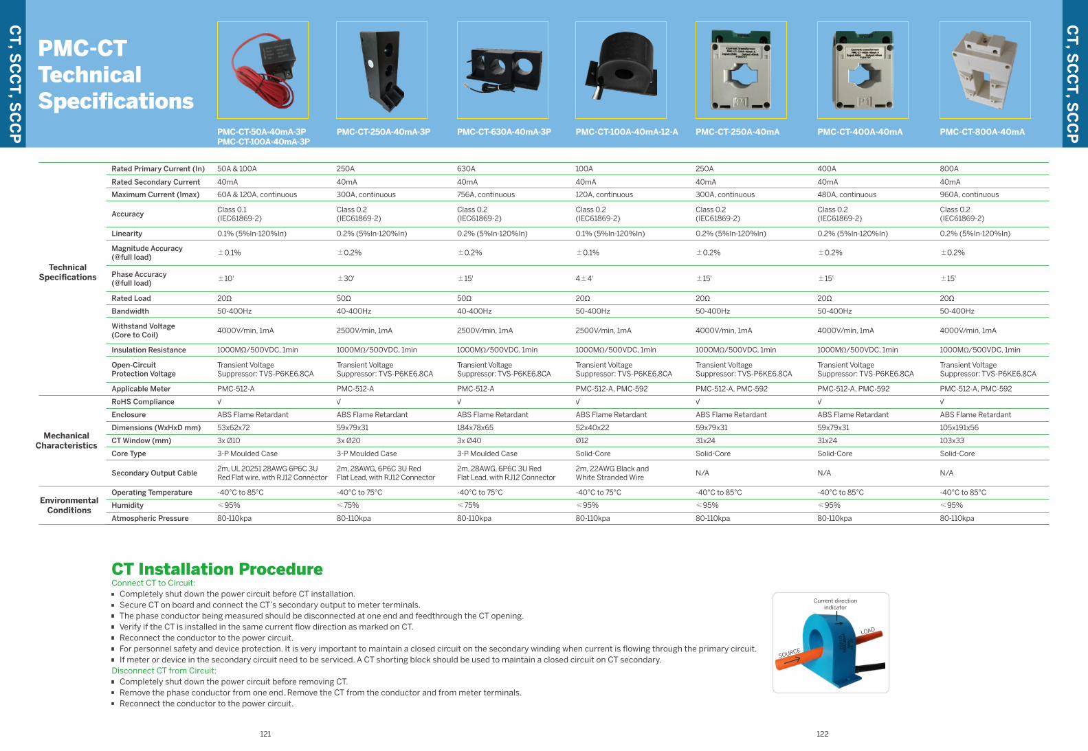
122121
CT Installation ProcedureConnect CT to Circuit:· Completely shut down the power circuit before CT installation. · Secure CT on board and connect the CT’s secondary output to meter terminals.· The phase conductor being measured should be disconnected at one end and feedthrough the CT opening.· Verify if the CT is installed in the same current flow direction as marked on CT. · Reconnect the conductor to the power circuit.· For personnel safety and device protection. It is very important to maintain a closed circuit on the secondary winding when current is flowing through the primary circuit.· If meter or device in the secondary circuit need to be serviced. A CT shorting block should be used to maintain a closed circuit on CT secondary.Disconnect CT from Circuit:· Completely shut down the power circuit before removing CT.· Remove the phase conductor from one end. Remove the CT from the conductor and from meter terminals.· Reconnect the conductor to the power circuit.
PMC-CTTechnicalSpecifications
LOAD
SOURCE
Current directionindicator
PMC-CT-800A-40mA
TechnicalSpecifications
MechanicalCharacteristics
EnvironmentalConditions
Rated Primary Current (In)
Rated Secondary Current
Maximum Current (Imax)
Accuracy
Phase Accuracy(@full load)
Bandwidth
Withstand Voltage(Core to Coil)
Insulation Resistance
Open-CircuitProtection Voltage
Magnitude Accuracy(@full load)
Linearity
Rated Load
RoHS Compliance
Operating Temperature
Humidity
Atmospheric Pressure
Secondary Output Cable
Enclosure
CT Window (mm)
Dimensions (WxHxD mm)
Core Type
Applicable Meter
Class 0.2(IEC61869-2)
800A
40mA
960A, continuous
±15'
50-400Hz
4000V/min, 1mA
1000MΩ/500VDC, 1min
Transient VoltageSuppressor: TVS-P6KE6.8CA
±0.2%
0.2% (5%In-120%In)
20Ω
√
105x191x56
-40°C to 85°C
≤95%
80-110kpa
N/A
ABS Flame Retardant
103x33
Solid-Core
PMC-512-A, PMC-592
PMC-CT-250A-40mA
Class 0.2(IEC61869-2)
250A
40mA
300A, continuous
±15'
50-400Hz
4000V/min, 1mA
1000MΩ/500VDC, 1min
Transient VoltageSuppressor: TVS-P6KE6.8CA
±0.2%
0.2% (5%In-120%In)
20Ω
√
59x79x31
-40°C to 85°C
≤95%
80-110kpa
N/A
ABS Flame Retardant
31x24
Solid-Core
PMC-512-A, PMC-592
PMC-CT-100A-40mA-12-A
Class 0.2(IEC61869-2)
40mA
4±4'
50-400Hz
2500V/min, 1mA
1000MΩ/500VDC, 1min
Transient VoltageSuppressor: TVS-P6KE6.8CA
±0.1%
100A
120A, continuous
0.1% (5%In-120%In)
20Ω
52x40x22
√
PMC-512-A, PMC-592
-40°C to 75°C
≤95%
80-110kpa
2m, 22AWG Black andWhite Stranded Wire
ABS Flame Retardant
Ø12
Solid-Core
PMC-CT-250A-40mA-3P
250A
40mA
±30'
50Ω
√
Class 0.2(IEC61869-2)
300A, continuous
40-400Hz
2500V/min, 1mA
1000MΩ/500VDC, 1min
Transient VoltageSuppressor: TVS-P6KE6.8CA
±0.2%
0.2% (5%In-120%In)
PMC-512-A
59x79x31
-40°C to 75°C
≤75%
80-110kpa
2m, 28AWG, 6P6C 3U RedFlat Lead, with RJ12 Connector
ABS Flame Retardant
3x Ø20
3-P Moulded Case
PMC-CT-400A-40mA
Class 0.2(IEC61869-2)
400A
40mA
480A, continuous
±15'
50-400Hz
4000V/min, 1mA
1000MΩ/500VDC, 1min
Transient VoltageSuppressor: TVS-P6KE6.8CA
±0.2%
0.2% (5%In-120%In)
20Ω
59x79x31
√
-40°C to 85°C
≤95%
80-110kpa
N/A
ABS Flame Retardant
31x24
Solid-Core
PMC-512-A, PMC-592
√
PMC-CT-630A-40mA-3P
Class 0.2(IEC61869-2)
630A
40mA
756A, continuous
±15'
40-400Hz
2500V/min, 1mA
1000MΩ/500VDC, 1min
Transient VoltageSuppressor: TVS-P6KE6.8CA
±0.2%
0.2% (5%In-120%In)
50Ω
PMC-512-A
184x78x65
-40°C to 75°C
≤75%
80-110kpa
2m, 28AWG, 6P6C 3U RedFlat Lead, with RJ12 Connector
ABS Flame Retardant
3x Ø40
3-P Moulded Case
PMC-CT-50A-40mA-3P PMC-CT-100A-40mA-3P
50A & 100A
40mA
60A & 120A, continuous
Class 0.1(IEC61869-2)
±10'
50-400Hz
4000V/min, 1mA
1000MΩ/500VDC, 1min
Transient VoltageSuppressor: TVS-P6KE6.8CA
±0.1%
0.1% (5%In-120%In)
20Ω
√
PMC-512-A
-40°C to 85°C
≤95%
80-110kpa
2m, UL 20251 28AWG 6P6C 3U Red Flat wire, with RJ12 Connector
ABS Flame Retardant
53x62x72
3x Ø10
3-P Moulded Case
CT
, SC
CT
, SC
CP
CT
, SC
CT
, SC
CP
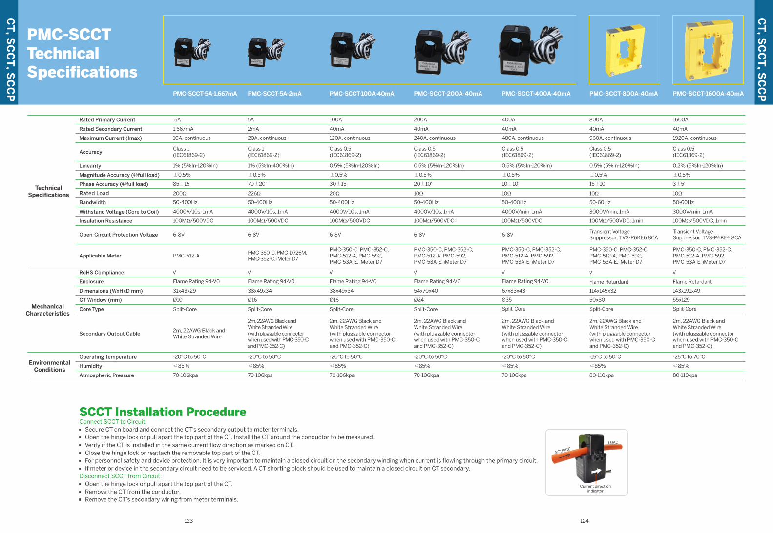
123 124
SCCT Installation ProcedureConnect SCCT to Circuit:· Secure CT on board and connect the CT’s secondary output to meter terminals.· Open the hinge lock or pull apart the top part of the CT. Install the CT around the conductor to be measured. · Verify if the CT is installed in the same current flow direction as marked on CT. · Close the hinge lock or reattach the removable top part of the CT.· For personnel safety and device protection. It is very important to maintain a closed circuit on the secondary winding when current is flowing through the primary circuit.· If meter or device in the secondary circuit need to be serviced. A CT shorting block should be used to maintain a closed circuit on CT secondary. Disconnect SCCT from Circuit:· Open the hinge lock or pull apart the top part of the CT. · Remove the CT from the conductor.· Remove the CT’s secondary wiring from meter terminals.
LOAD
SOURCE
PMC-SCCTTechnicalSpecifications
Current directionindicator
PMC-SCCT-1600A-40mAPMC-SCCT-800A-40mA
TechnicalSpecifications
MechanicalCharacteristics
EnvironmentalConditions
Rated Primary Current
Rated Secondary Current
Bandwidth
Withstand Voltage (Core to Coil)
Insulation Resistance
Open-Circuit Protection Voltage
Accuracy
Phase Accuracy (@full load)
Linearity
Magnitude Accuracy (@full load)
Maximum Current (Imax)
Rated Load
Enclosure
Secondary Output Cable
RoHS Compliance
Dimensions (WxHxD mm)
Core Type
CT Window (mm)
Operating Temperature
Humidity
Atmospheric Pressure
Applicable Meter
50-60Hz
3000V/min, 1mA
100MΩ/500VDC, 1min
Transient VoltageSuppressor: TVS-P6KE6.8CA
1600A
40mA
Class 0.5(IEC61869-2)
3±5'
0.2% (5%In-120%In)
±0.5%
1920A, continuous
10Ω
Flame Retardant
2m, 22AWG Black andWhite Stranded Wire(with pluggable connectorwhen used with PMC-350-Cand PMC-352-C)
√
143x191x49
Split-Core
55x129
-25°C to 70°C
≤85%
80-110kpa
PMC-350-C, PMC-352-C,PMC-512-A, PMC-592,PMC-53A-E, iMeter D7
10Ω
800A
40mA
√
50-60Hz
3000V/min, 1mA
100MΩ/500VDC, 1min
Transient VoltageSuppressor: TVS-P6KE6.8CA
Class 0.5(IEC61869-2)
15±10'
0.5% (5%In-120%In)
±0.5%
960A, continuous
Flame Retardant
2m, 22AWG Black andWhite Stranded Wire(with pluggable connectorwhen used with PMC-350-Cand PMC-352-C)
114x145x32
Split-Core
50x80
-15°C to 50°C
≤85%
80-110kpa
PMC-350-C, PMC-352-C,PMC-512-A, PMC-592,PMC-53A-E, iMeter D7
PMC-SCCT-5A-2mA
5A
√
226Ω
50-400Hz
4000V/10s, 1mA
100MΩ/500VDC
6-8V
2mA
Class 1(IEC61869-2)
70±20’
1% (5%In-400%In)
±0.5%
20A, continuous
Flame Rating 94-V0
2m, 22AWG Black andWhite Stranded Wire(with pluggable connectorwhen used with PMC-350-Cand PMC-352-C)
38x49x34
Split-Core
Ø16
-20°C to 50°C
≤85%
70-106kpa
PMC-350-C, PMC-D726M, PMC-352-C, iMeter D7
√
PMC-SCCT-100A-40mA
20Ω
50-400Hz
4000V/10s, 1mA
100MΩ/500VDC
6-8V
100A
40mA
Class 0.5(IEC61869-2)
30±15'
0.5% (5%In-120%In)
±0.5%
120A, continuous
Flame Rating 94-V0
2m, 22AWG Black andWhite Stranded Wire(with pluggable connectorwhen used with PMC-350-Cand PMC-352-C)
38x49x34
Split-Core
Ø16
-20°C to 50°C
≤85%
70-106kpa
PMC-350-C, PMC-352-C,PMC-512-A, PMC-592,PMC-53A-E, iMeter D7
PMC-SCCT-5A-1.667mA
5A
200Ω
1.667mA
50-400Hz
4000V/10s, 1mA
100MΩ/500VDC
6-8V
Class 1(IEC61869-2)
85±15'
1% (5%In-120%In)
±0.5%
10A, continuous
Flame Rating 94-V0
2m, 22AWG Black andWhite Stranded Wire
√
31x43x29
Split-Core
Ø10
-20°C to 50°C
≤85%
70-106kpa
PMC-512-A
PMC-SCCT-400A-40mA
10Ω
50-400Hz
4000V/min, 1mA
100MΩ/500VDC
6-8V
400A
40mA
Class 0.5(IEC61869-2)
10±10'
0.5% (5%In-120%In)
±0.5%
480A, continuous
Flame Rating 94-V0
2m, 22AWG Black andWhite Stranded Wire(with pluggable connectorwhen used with PMC-350-Cand PMC-352-C)
√
67x83x43
Split-Core
Ø35
-20°C to 50°C
≤85%
70-106kpa
PMC-350-C, PMC-352-C,PMC-512-A, PMC-592,PMC-53A-E, iMeter D7
PMC-SCCT-200A-40mA
√
10Ω
Class 0.5(IEC61869-2)
40mA
20±10'
50-400Hz
4000V/10s, 1mA
100MΩ/500VDC
6-8V
0.5% (5%In-120%In)
±0.5%
200A
240A, continuous
Flame Rating 94-V0
54x70x40
2m, 22AWG Black andWhite Stranded Wire(with pluggable connectorwhen used with PMC-350-Cand PMC-352-C)
Split-Core
Ø24
-20°C to 50°C
≤85%
70-106kpa
PMC-350-C, PMC-352-C,PMC-512-A, PMC-592,PMC-53A-E, iMeter D7
CT
, SC
CT
, SC
CP
CT
, SC
CT
, SC
CP
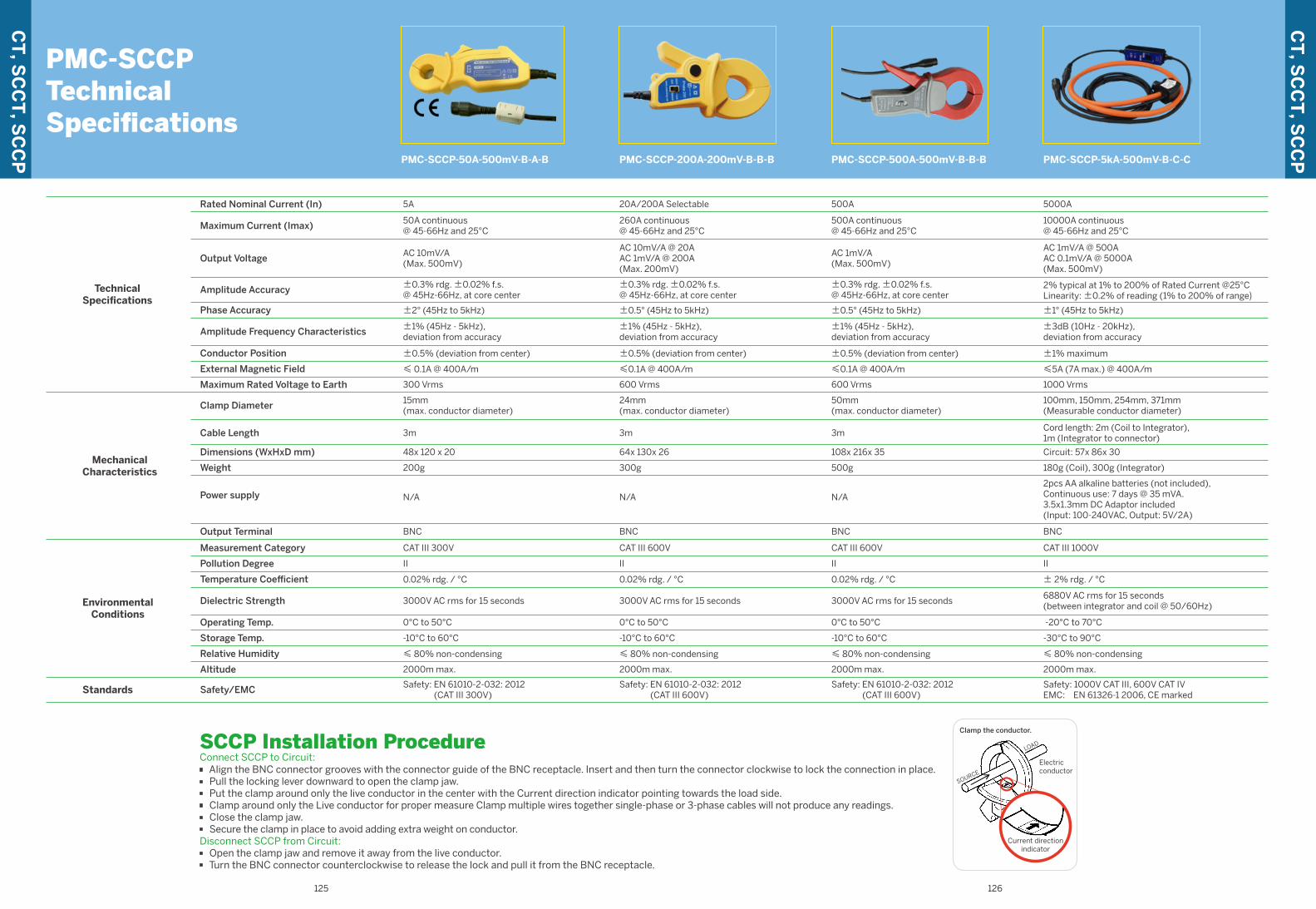
125 126
SCCP Installation ProcedureConnect SCCP to Circuit:· Align the BNC connector grooves with the connector guide of the BNC receptacle. Insert and then turn the connector clockwise to lock the connection in place.· Pull the locking lever downward to open the clamp jaw.· Put the clamp around only the live conductor in the center with the Current direction indicator pointing towards the load side.· Clamp around only the Live conductor for proper measure Clamp multiple wires together single-phase or 3-phase cables will not produce any readings.· Close the clamp jaw.· Secure the clamp in place to avoid adding extra weight on conductor.Disconnect SCCP from Circuit:· Open the clamp jaw and remove it away from the live conductor.· Turn the BNC connector counterclockwise to release the lock and pull it from the BNC receptacle.
PMC-SCCPTechnicalSpecifications
LOAD
SOURCE
Clamp the conductor.
Electricconductor
Current directionindicator
TechnicalSpecifications
EnvironmentalConditions
MechanicalCharacteristics
Standards
Rated Nominal Current (In)
Maximum Current (Imax)
Output Voltage
Amplitude Accuracy
Phase Accuracy
Amplitude Frequency Characteristics
Conductor Position
External Magnetic Field
Maximum Rated Voltage to Earth
Safety/EMC
Measurement Category
Pollution Degree
Temperature Coefficient
Dielectric Strength
Operating Temp.
Storage Temp.
Relative Humidity
Altitude
Clamp Diameter
Cable Length
Dimensions (WxHxD mm)
Weight
Power supply
Output Terminal
PMC-SCCP-50A-500mV-B-A-B
5A
II
50A continuous@ 45-66Hz and 25°C
AC 10mV/A(Max. 500mV)
±0.3% rdg. ±0.02% f.s.@ 45Hz-66Hz, at core center
±2° (45Hz to 5kHz)
±1% (45Hz - 5kHz),deviation from accuracy
±0.5% (deviation from center)
≤ 0.1A @ 400A/m
300 Vrms
Safety: EN 61010-2-032: 2012(CAT III 300V)
CAT III 300V
0.02% rdg. / °C
3000V AC rms for 15 seconds
0°C to 50°C
-10°C to 60°C
≤ 80% non-condensing
2000m max.
15mm(max. conductor diameter)
3m
48x 120 x 20
200g
N/A
BNC
20A/200A Selectable
260A continuous@ 45-66Hz and 25°C
AC 10mV/A @ 20AAC 1mV/A @ 200A(Max. 200mV)
±0.3% rdg. ±0.02% f.s.@ 45Hz-66Hz, at core center
±0.5° (45Hz to 5kHz)
±1% (45Hz - 5kHz),deviation from accuracy
±0.5% (deviation from center)
≤0.1A @ 400A/m
600 Vrms
Safety: EN 61010-2-032: 2012(CAT III 600V)
CAT III 600V
0.02% rdg. / °C
3000V AC rms for 15 seconds
0°C to 50°C
-10°C to 60°C
≤ 80% non-condensing
2000m max.
II
24mm(max. conductor diameter)
64x 130x 26
3m
300g
N/A
BNC
PMC-SCCP-200A-200mV-B-B-B
500A continuous@ 45-66Hz and 25°C
AC 1mV/A(Max. 500mV)
±0.3% rdg. ±0.02% f.s.@ 45Hz-66Hz, at core center
±0.5° (45Hz to 5kHz)
±1% (45Hz - 5kHz),deviation from accuracy
±0.5% (deviation from center)
≤0.1A @ 400A/m
600 Vrms
500A
Safety: EN 61010-2-032: 2012(CAT III 600V)
CAT III 600V
0.02% rdg. / °C
3000V AC rms for 15 seconds
0°C to 50°C
-10°C to 60°C
≤ 80% non-condensing
2000m max.
II
50mm(max. conductor diameter)
108x 216x 35
3m
500g
N/A
BNC
PMC-SCCP-500A-500mV-B-B-B
II
5000A
10000A continuous@ 45-66Hz and 25°C
AC 1mV/A @ 500AAC 0.1mV/A @ 5000A(Max. 500mV)
2% typical at 1% to 200% of Rated Current @25°CLinearity: ±0.2% of reading (1% to 200% of range)±1° (45Hz to 5kHz)
±3dB (10Hz - 20kHz),deviation from accuracy
±1% maximum
≤5A (7A max.) @ 400A/m
1000 Vrms
Safety: 1000V CAT III, 600V CAT IVEMC: EN 61326-1 2006, CE marked
CAT III 1000V
± 2% rdg. / °C
6880V AC rms for 15 seconds(between integrator and coil @ 50/60Hz)
-20°C to 70°C
-30°C to 90°C
≤ 80% non-condensing
2000m max.
100mm, 150mm, 254mm, 371mm(Measurable conductor diameter)
Cord length: 2m (Coil to Integrator),1m (Integrator to connector)
Circuit: 57x 86x 30
180g (Coil), 300g (Integrator)
2pcs AA alkaline batteries (not included),Continuous use: 7 days @ 35 mVA.3.5x1.3mm DC Adaptor included(Input: 100-240VAC, Output: 5V/2A)
BNC
PMC-SCCP-5kA-500mV-B-C-C
CT
, SC
CT
, SC
CP
CT
, SC
CT
, SC
CP
Related Documents


