DOEINASA12749-7911 VOI 1 NASA CR-159670 COO-2749-42 Baseline Automotive Gas Turbine Engine Development Program Final Report (BASA-CB-159670) BASELINE AUTOBOTIVB GAS Y 80-24520 TUBBIIE EIGIIB DBVELOPMEYT PROGRAM Final Report (Chrysler Corp.) 182 p EC A09/UP A01 CSCL 21A Onclas G3/37 20915 Edited By C. E. Wagner and R. C. Pampreen Chrysler Corporation netroit, Michigar. 48288 'Prepared for National Aeronautics and Space Administration Lewis Research Center Ilnder Contract EY-76-C-02-2749.AOll for U.S. Department of Energy Office of Conservation and Solar Applications Division of Transportation Energy Conservation

Welcome message from author
This document is posted to help you gain knowledge. Please leave a comment to let me know what you think about it! Share it to your friends and learn new things together.
Transcript

DOEINASA12749-7911 VOI 1 NASA CR-159670 COO-2749-42
Baseline Automotive Gas Turbine Engine Development Program Final Report
( B A S A - C B - 1 5 9 6 7 0 ) B A S E L I N E AUTOBOTIVB GAS Y 80-24520 T U B B I I E E I G I I B DBVELOPMEYT PROGRAM Final Report (Chrysler Corp.) 182 p EC A09/UP A 0 1
CSCL 21A Onclas G 3 / 3 7 20915
Edited By C. E. Wagner and R. C. Pampreen Chrysler Corporation netroit, Michigar. 48288
'Prepared for National Aeronautics and Space Administration Lewis Research Center Ilnder Contract EY-76-C-02-2749.AOll
for U.S. Department of Energy Office of Conservation and Solar Applications Division of Transportation Energy Conservation
DOE/NASA/2740-79/1 Volume 1 NASA CR-159670 COO-2749-42
Baseline Automotive Gas Turbine Engine Development Program Final Report
Edited By C.E. Wagner and R.C. Pampreen Chrvsler Corporation I>ctrait. h!~zhigan 4813Y
Prepared for National Aeronautics and Space Administration l e\vls Rcsc.~rch Center Cleveland, Ohio 44 135 Under Contr.~ct EL -76-C-C2-: '49-
For [IS. Department of Energy C1tiit.e of Conservation and Solar Applications 1)iv:clon ot Transport.~tion Energy Conserv~tion Washington, I?.C 20545
llnder Intcr.~pcncy Agreement EC-77-A-31-1040
Aclu\owledgement This report covers all work performed under DOE Contract No. EY-76-C-02-2749.A011 frcm Novem- ber, 1972, to June, 1979. The contract was initiated by the U.S. Environmental Protection Agency, was subsequently transferred to the Energy Research an: Development Administration, and was finally transferred to the Heat Engine Systems Brancl~, Division of Transportation Energy Conservation of the U.S. Department of Energy. Mr. Charles E. Wagner was the Chrysler Corporation Program Manager. Mr. Paul T. Kerwin, NASA-Lewis Research Center, has been the Project Officer since 1977. Previous Project Officers were David G. Evans, NhSA-Lewis Research Center, and Thomas M. Sebestyen, EPA. Mr. Robert A. Mercure, DOE - Division of Transportation Energy Conservation, has been the Project Coordinator since the technical management was turned over to NASA-Lewis Research Center through an interagency agreement. This program was origi*~ally proposed, awarded, structured, and launched at Chrysler under the direction of George J. Hueher, Jr.. Director of Research, and James P. Franceschina, Chief Engineer of Power Plant Research.
Contributors to this report were: A. Billington, T. Golec, J.V. Gross, H.P. LeFevre, E.M. Kohl, 1.1. Le- wakowski, C.H. Mader, T.D. Nogle (Laboratory Personnel), F. Dosenberger, P.K. Jain, R.A. Kost, D S. Musgrave, R.C. Pampreen, N.W. Sparks. R. Swiatek (Design and Analysis), C. Belleau. W.F. Bertrand. J.M. Corwin, F.A. Hagen, J.R. Kirberg, A. Roy, P.J. Willson (High Temperature Materials), C.M. Elliott (Continuously Variable Transmission), and W.D. Bastow, O.K. Thiel (Piston-Engine Performance Analysis).
TABLE OF .......................................................................................................... CONTENTS ~ k t n c t
............................................................................................................................... 1.0 Sumrmry 2.0 Introduction .......................................................................................................................... 3.0 Bastline h & w Testing .......................................................................................................
3.1 Engine Performance ........................................................................................................ ............................................................................................ 3.2 Engine Endurance Testing
4.0 Baseline Vehicle Testing ...................................................................................................... ..................................................................................................... 4.1 Vehicle Performance
................................................................................................................ 4.2 Noise Control ............................................................................................ 4.3 Inlet and Fxhaust Ducting
..................................................................................................... 4.4 Car Comfort Systems 4.5 Vehicle Operation Log ...................................................................................................
.................................................................................................. 4.6 Vehicle Brake System 5.0 Advanced Combustor Systems ...........................................................................................
5.1 Emiseon Control ............................................................................................................ .......... 5.2 Combustor Development ............................................................................
............ 5.3 Transient Operation ........................................................................ ................................................................................................... 5.1 Multi-Fuel Operation
............................................................................................................. 5.5 Odor Evaluation ............................................................................................... 5 6 Pressure-Drop Effects
5.7 Combustor Materials ...................................................................................................... 6.0 Ceramic Regenerators ..........................................................................................................
...................................................................................................................... 6.1 Background 6.2 Conversion to Ceramic Regenerators ........................................................................... 0.3 Improved-Effectiveness Matrix Devel ...................................................................... 0.1 Thermal Analysis .......................................................................................................
................................................................................................................... 7.0 Engine Controls 7.1 Baseline Hydromechanical Control .............................................................................. 7.2 Electronic Control System ............................................................................................. 7.3 Electronic Control Implementation ..............................................................................
........................................................................................ 7.4 Fuel Metering Components ........................................................................................................................... 7 5 Snsors
....................................................................................................................... 7.6 Actuators 7.7 Electronic Engine-Control Summ~ry ............................................ ..- ...........................
8.0 Low-Cost Turbine Rotors ................................................................................................... 8.1 Gatoriring Process ..........................................................................................................
..................................................................................................... 8.2 AiRefrac Process .............................................................................. 9.0 Enginelcontrol Oil Supply System
.................................................................................. 10.0 Hydromechanical Transmission .................................................................................... 10 1 Summary of MTI Report
10.2 Application . of CVT to Reciprocating Engine ............................................................ 10 3 Application of CVT to Gas Turbine Engine ....................................................... 10.1 Transmission Cost Comparison ..............................................................................
..................................................................................................... 10 5 Summary to Date 11.0 Power-Turbine-Driven Accessories (Free-Rotor) ....................................................
........................................................................................... 11 i Preliminary Testing ..................................................................................... 11.2 'rr.1 nsient Operating Line
11 . 3 Low-Speed Engine Characteristics ..................................................................... 11.4 Effect of Regenerator Speed on Performance ................................................. 11 5 Engine Conversion for Vehicle Application .....................................................
............................................................................................ 11 . 6 Vehicle Trsts 12.0 Power Augmentation by Water Injection ............................................................
................................................................................... 12 1 Four-Norzle Testing
.............................................................................. 12 2 Two-Nozzle Test~ng . . . . . . . . . . . . . . . . . . . . . . . . . . . . . . . . . . . . . . . . . . . . . . . . . . . . . . . . . . . . . . . . . . 12 3 Single-Nozzle Testing
......................................................................................... 12 1 Final Velliclc Testing

TABLE OF CONTENTS (continued)
..................................................................................... 13.0 Power Augmentation by VlGV .............................................................................. 13.1 Engine Operation with VIGV
13.2 VlCv Design ........................................................................................................... ............................................................................................. 13.3 Compressor Rig Testing
13.4 Compressor Results from :' Mne Testing .......................................................... ...................................... .............................. 13.5 Turbine Analysis from Engine Testing -.
............................................................................................... 14.0 Higher Cycle Temperahue 14.1 Alloy Selection .............................................................................................................
................................................................................. 14.2 Bulkhead Housing Investigation ............................................................................................................ 15.0 LintrIess Insulation
................................................................................................................ 15.1 Background 15.2 Test Results .................................................................................................................
............................................................................................................................ 16.0 CancluJion ...................................................................................................................................... References
Tables and Figures ........................................................................................................................
Abstract This is the first of four volumes of the contract final report, which summarizes a11 of the work performed in a go\zmment-sponsored Automotive Gas Turbine Development Program (DOE Contract No. EY-7e-C-02-2749.A011). In this first volume of the contract final report, results rre presented fmm tests which were conducted on a Baseline Engine to document the Automotive Gas Turbine State-of-the-Art at the start of the program and to evaluate certain component improvement concepts. The documentation consisted of defining the performance characteristics of the engine and of a vehicle powered by this engine.
Camponent improvements in the Baseline Engine were to be evaluated on engine dynamometer tests, in the complete vehicle on a chassis dynamometer, and on road tests. These concepts included: advanced combustors, ceramic regenerators, an integrated control system, low-cost turbine material, a continuously variable transmission, power-turbine-driven accessories, power augmentation, and linerless insulation in the engine housing. Successful verification of improvements was to be the basis of upgrading the engine by incorporating these technology advancements in a new design called the Upgraded Engine.
1.0 The Chrysler sixth-generation engine was used to document existing automotive gas turbine state-of- SUMMARY the-art and was identified as the contract Baseline Engine. The documentation consisted of defining the
performance characteristics of the engine itself and of a vehicle powered by this engine. Subsequently, an extensive component-improvement program was carried out on the Baseline Engine for the purpose of evaluatingcertain concepts which, if proved beneficial, would be incorporated into the design of the Upgraded Engine. These concepts included:
1. Advanced combustor systems 2. Ceramic regenerator 3. Integrated control system 4. Low-cost turbine rotors 5. Engine/control oil supply system 6. Hydromechanical transmission 7. Power-turbine-driven accessories 8. Power augmentation:
Water injection Variable inlet guide vanes
9. Higher cycle temperature 1C. Linerless insulation
Where applicable, vehicular evaluation of these concepts w2: identified as Task 6.
On a standard automotive day (85°F Temp., 29.92 Hg. Press.) the Baseline Engine cielivered 150 HP at design speed and at a design-speed turbine-inlet-temperature of 1850°F. The design yrt'.i- sure ratio is 1.1:l at a mass flow rate of 2.3 1bs:sec and a rotctional speed of 41,610 rpm. Design- speed SFC is 0.9 lbs./hp-hr; idle-power SFC is 1.90. \'ehicle testing showed a combined-cycle tile1 econoiny of 8.0 mpg (gasoline) and 8.8 mpg (diesel) with zero-60 mph accelerat~on time ot 11 seconds In a 1500-lb vehicle.
The following summarizes the testing camed out on the different advanced concepts.
A variety of combustor configurations were investigated: pre-mixed/pre-vaporized, droplet- diffusion, dual-stage, torch ignitor and variable geometry. The configuration w ~ t h pre-mixed/ pre-vaporized combustion combined with a torch ignitor yielded the lowest emission values (0 41 gram/mile HC, 3.4 grams/nlile CO, and 3.1 gramsimile NOx) and was bebt suited to vehicle driveability.
Three ceramic core configurations were investigated for the regenerator. Within the range rif ~ e - cific flow required for the Upgraded Engine, a configuration with a triangular shape yielded values of effectiveness as much as 4 points higher than values for the metallic core used as reference
Testing - :wed that engine controls must be more sophisticated than the original controls used on the Baseline Engine. A closed-loop control on turbine exit temperature was successfully applied to the Baseline Engine.
Two new manufacturing processes were explored for potential for low-cost production of turbine -otors. Both the reusable pattern process by the AiRese~rch Casting Division of the G.~rrett Cor- poration (AiRefrac) and the superplastic forging technique (Gatorizing) by the Pratt & Whitney Aircraft group showed some promise.
Tests conducted on the hydromechanical continuously variable transmission (CVT) revealed little gain in fuel economy with this type of CVT. Other types, such a s hclt-drive, wert. recommended for investigation.
The arrangement of driving engine accessories from the power turbine instead of the gas gener'ttor was show - to be more practical and of lower cost
Power augmentation with water injection was successfully demonstrated, but the results showed a strong need for erosion protection for the compressor. Augmentation of compressor performance with vari.:L.rle inlet guide vanes (VIGV) was demonstrated, although the incredse in design-speed
pressure ratio was 5.4% versus the goal of 7.8%. Power augmentation with VIGV was 4% versus the goal of 12%. For the amount of compressor augmentation achieved, the engine power augmen- tation should have been 8%. The miss in achievable augmentation was caused by deteriorated turbine efficiency at maximum compressor augmentation. Aerodynamic design parameters would have to be revised to employ augmentation on the Upgraded Engine.
Two high-temperature alloys wen investigated for the Upgraded Engine compressor-turbine ro- tor: IN-792/Hf and MAR-M-246. Rotors made of MAR-M-246 wen cast successfully in the AiRefrac process. No sound castings wen made of IN-79t/Hf with this process.
a The use of linerless insulation was successfully demonstrated.
All the advanced concepts, except for items 4 and 6 above were applied to the design of the Upgraded Engine. The development effort camed out on the Baseline Engine and the test results are described in this volume.

2.0 This part of the contract consisted of four distinct areas of work which were carried out under five INTRODUCTION program tasks. These areas consisted of:
I. Document.ltion of Baseline Engine performance chacteristics (Task 1.0) 2. Documentation of vehicle performance with Baseline Engine (Task 2.0) 3. Evaluation, on Baseline Engine, of advanced concepts to be applied to the Upgraded Engine (Tasks
4, 5) 4. Where applicable, evaluation of advanced concepts with vehicular testing (Task 6)
The Chrysler sixth-generation engine was selected as the Baseline Engine. &door sedans weighing about 4,500 Ibs. were used to evaluate vehicle performance with the Baseline Engine as originally designed and as modified by the different advanced concepts. The advanced concepts which were eval- uated consisted of:
1. Advanced combustor systems (Task 5.1) 2. Ceramic regenerator (Task 5.2) 3. Integrated control system (Task 5.3) 4. Low-cost turbine rotors (Task 5.4) 5. Engine/control oil supply system (Task 5.6) 6. Hydromechanical transmission (Task 5.7) 7. Power-turbine-driven accessories (Task 5.8) 8. Power augmentation:
Water injection (Task 5.9) Variable inlet guide vanes (Task 5.10)
9. Higher cycle temperature (Task 5.11) 10. Linerless insulation (Task 5.12)

3.0 The Baseline Engini, Figures 1 and 2, was released in January, 1965. The engine was originally targeted BASELINE- for a 3600-lb. vehicle exhibiting fuel economy and performance comparable to vehicles of that date. ENGINE Principal design goals were: improved rotor response, cost reduction, and capability of driving TESTING production type vehicle accessories, specifically air conditioning and power steering from the power
turbine. Exhaust emissions, particularly NOx, wen not a consideration in the design of the combustion system although CO and HC were controlled to achieve a burner efficiency approaching 100% with minimum odor, carbon formation, et cetera. Power plant weight and geometric configuration were determined by requirements to have reasonable mass and to fit an existing vehicle.
The engine is a 4:l pressure ratio, regenerative, free ,power-turbine design. It incorporates a single-stage centrifugal compressor, two axial turbine stages and variable power turbine nozzle vanes.
3.1 Engine Performance
Pertinent 85.F full-power characteristics along with other descriptive data are itemized on Table 1. Ten of these engines as well as three 1973 intermediate-size vehicles were built as baseline hardware for this program. Engine characterization is shown in Table 2, and station notation references are shown on Figures 3 and 4. Typical engine performance is shown in Figures 5,6,7,8, and engine exhaust emissions on Figure 9. Vehicle exhaust emission levels, CO and NOx, were lower than those required to meet the 1975 standards (0.4 gram/mile HC, 3.4 grams/mile CO and 3.1 grams/mile NOx).
3.2 Evaluation of Baseline Engine durability relied principally on dynamometer testing. Two endurance Engine Endurance cycles were used which were designed to subject turbine components to an accelerated life test through Testing the use of a transient-type cycle rather than the steady-state mode.
The initial cycle evolved from years of test experience from the Contractor's proving grounds, the high- ways of this country and accumulated knowledge of various test-cell endurance schedules. Since steady state operation in a vehicle is the exce~tion rather than the rule, an all-encompasing test cycle, including several starts, part-and full-throttle accelerations and a shutdown period to expose rotor bearings to soak back temperatures, was chosen.
The cycle for the Baseline Engine was of one hour duration and included:
9 starts 15 wide-open-throttle accelerations 4 part-throttle acceler,i+ions 14.5 minutes total shutdobqn time (includes 10.5 minute soak period).
This was equivalent to an average vehic:? speed of 49 MPH (assuming typical axle ratio, tire size, etc.). An automatic programmer controlled the I.. over the one hour cycle. Safeties were provided for overtemperature, overspeed, low oil pressure, start condition, et cetera. Strip-chart recorders provided a continuous record of events. Typical speed recordings which kharacterize the cycle are shown in Figure 10. Failed or malfunctioning parts were repaired or replaced as necessary.
A Baseline Engine was tested on this cycle for total of 4653.7 hours. Total ttit time on some of the significant components at final teardown is shown on Table 3. Where applicable, total test hours are also shown on components replaced at earlier teardnwn inspections because of part failure or update as indicated.
Final teardown revealed that the most significantly distressed components were lo~dted ill the burner section although the only non-useable part was the burner tube. Figures 11 and 12 display the f11st- stage turbine rotor and nozzle, respectively. Note slight erosion at the leading edge. Metallurgically the components were considered acceptable for further testing.
The second endurance cycle, shnwn on Figure 13, alternately subjects the matrix to 1400ei: at high- power conditions, followed by rapid cool-down to 900.F at idle. The thermal transients in this test sequence are far more extreme than any anticipated vehicular duty cycle, and they are designed to screen various matrix configurations for susceptibility to thermal fatigue cracking. See Figure 14. An acceleration from 60% to 100% speed was included to subject the elastomeric core ring-gear attach- ment system to high torque conditions.
4.0 BASELINE VEHICLE TESTING
4.1 Vehicle Perfonnance
Three 1973 intermediate-size, 4-door sedans were modified to accept the Baseline Engine. The mod- ifications ~ncluded:
Widen front track of chassis. Modify front cross-member. Relocate suspension-system torsion-bar rear anchors, revise rear-frame cross-rnemb. ~ d i f p underbody to provide clearance fcr exhaust ducts. Relocate steering gear and modify steering linkage and column. Modify radiator yoke to receive air conditioning condensor, electric fan and engine and transmission oil coolers. Modify front-fender sheet-metal to accept engine inlet ducting; install in-tank fuel pump and return-line. Install hydraulic brake booster and accumulator. Modify transmission linkage. Revise car comfort system-install hot-gadwater heat-exchanger and air-conditioning com- pressor (axial type). Revise wiring harness as required.
Figure 15 shows a cross section and Figure 16 a fully assembled vehicle.
Vehicle performance witk the Baseline Engine was documented for several configurations at the proving grounds using est; .ished test procedures. Driveability was evaluated during several road trips and ride/drive demonstrations.
Figure 17 shows the uncorrected speed-time and distance trace for two vehicles Their weights and ambient-temperature test conditions are noted. The speed-time values are also shown with and with- out air conditioning corrected to a 85.F day. Performance was judged satisfactory-4-60 MPH in 11 seconds. Figure 18 shows the engine/vehicle braking capability which compared favorably to the cur- rent conventional vehicles The braking position was fixed by the control sy:,tem, and the full engine braking potential could not be realized due to linkage limitations.
Figure 19 shows the fuel economv tor varying road-load speeds to 90 MPH, ,it turb~ne e\li.~ust tenlperatures ot 1300°F (corrected tor standard day) and 1300°F (actilal) tor am-;ient teniperat~~rt.\ ot 33-38°F. Metal regentBrntor cores were u t i l ~ ~ e d tor these tests. An iniIic,~ted, iuel econom! - particul.1rly at low speed - would be less than w ~ t h a comparable spark-~gn~;ion re#-lprowhng engine. These tests were suppleniented by vehicle evaluation5 at ,lie EPA tac~l~ tv 1i1 . inn Arbor, hlich~gan, ancl ,ire discussed In Reterence 1. Combined illel economies ,>: 8.0 nip& (~.isoline) ,init 8.8 nips ( d i ~ ~ e l ) were n ~ e ~ i s u r r d .
These data were documented using an open-.oop hydromechanical control and, as a result, operating conditions were ~ . o t optimized. The introduction of the integrated eic.,,ronic control system (closed- loop on power turbine exhaust temperature) was expected to optimize vehicle operation in the drive ~ n d braking modes and to result in improved fuel economy and reduced emissions as described further in this report.
In summation, the majority of the evaluators who drove the vehicles judged the vehicle response as acceptable Most evaluators were totally satisfied with vehicle noise levels and driveability Overall ~ominents by technically knowledgeable personnel were favorable.
Table 4 describes the vehicles and summarizes the test hours and miles at the close of the program The fourth vehicle (Car 618) is a Chrysler-funded project that contributed extensively to the development of the combustor and electronic control systems.
4.1 Noise Control
4.3 Inlet and Exhaust Ducting
4.4 Vehicle Comfort Systems
Principal noise sources -,; gas turbine powerplants are:
1. airbornc intake high-frequency noise. 2, airborne exhausi ~ o i s e . 3. rotor noise. 4. high speed gear noise.
Airborne intake noise can be readily attenuated by directing the inlet air through a minimum of two duct bends of maximum allowable size and lined with a suitable acoustic material. Exhaust noise is treated in a similar manner. Additionally, as a general rule, minimiiation of noise at the exhaust termi- nus requires a diffusion section which reduces gas velocity to 100 ft./sec. at rated power.
Rotor-generated noise attributed to rotor imbalance arrd shaft bending can be negated by isolat~ng the rotor sleeve bearings from the bearing carrier via oil film damping, et cettra. This technique was successful in the Baseline Engines. Noise control of high-speed gearing required: precise manufacture of the involute surfaces, modification of the involute (crowning, surface finish and treatme.rt, such as Tufftriding), oil film-thickness control, et cetera. Gear-tooth-generated noise under lightly loaded conditions in drive-to-braking-mode of operation can be controlled by bonding aluminum dampers fabricated of fully annealed material (0.06-inch thick) to the gear disr with a suitable adhesive.
Baseline-vehicle proving-grounds tests for compliance with SAE Standard 1986a (wide-open throttle acceleration from 30 mph at 50 ft.) indicated sound levels of 75.1 and 75.0 dBA for the right and left sides respectively. By comparison, the EPA Prototype Vehicle Standard is 77 dBA, the legal standard is currently 86 dBA and equivalent reciprocating engines were measured at levels of 81-82 dBA. Static noise evaluations of a baseline vehicle and a 1974 conventional vehicle powered by a V8 engine are compared on Table 5.
Further improvements were made to the noise control of a second vehicle and were documented *t an independent test facility by EPA pe-zonnel. Discreet frequencies were taken, and the required A- weighting was applied to arrive at the results in Table 6. Thus, the noise level for the vehicle is 73 decibels, which is the highest average value recorded. The data in Table 6 were taken to obtain addi- tional information on the vehicle. Turtine whine was noticeable but not objectionable inside the velli- cle beeveen 35 and 55 mph.
An important consideration of gas-t~rbine/vehicle installation is the provision of adequate engine inlet ducting for the air filter capacity as well as noise control. Inlet restriction as well as exhaust restriction have an adverse and appreciable effect on engine perfomance. An exhaust pressure-loss of 1.0" H 2 0 results in a loss of 1 HP at design speed, as shown in Figure 20. Restrictions generated in the inlet- ductiilg/filter system manifest themselves in a similar loss of performance
; 11e use of an intermediate gas-to-water heat exchanger was predicated on two basic facto~s:
The pcssible toxic-gas effect of exposing Freon 12 tn high temperature. The ease of adapting the heat exchanger to the production configuration of '1 passenger c-jm- partment heating and air conditioning system and associated controls.
In this system, power turbine e x h a ~ ~ s t gas is passed through a gas-to-liquid heat exchanger containing conventional coolant (50% water/ethylene glycol), which is circulated through the standard vehicle passenger-compartment heater-core. A pump driven by a 12-Volt DC motor circulates the coolant through both the heat exchanger and the heater core. Thus, the passenger-compartment heater-core configuration retains the desirable reheat feature for the air conditioning system and eliminates any possibility of the decomposition of Freon due to contact with a high-temperature surface. Figure 21 is a schematic of this system. Production louver-controls are actuated from a vacuum reservoir which is integral with a trunk-mounted vacuum pump. Heater-system evaluation at -10.F demonstrated performance superior to that of syitems instdiled in conventional vehicles.
4.5 Vehicle running time/use cycle was automatically registclred on a bank of pressure-sensitive timers Vehicle installed in the vehicle's trunk, Figure 22. The timers were actuated via calibrated pressure switches and Operation Log sensed engine compressor pressure. The engine pressure signal approximated engine speed.
Figure 23 sumrnarires the engine duty cycle. Note that 46% of the total engine run time is at idle A majority of operating time is at speeds less than 80% gas generator speed.
The relationship between engine output power and accelerator pedal, also shown on Figure 23, was designed to simulate that of a conventional vehicle, e.g., 25% throttle is equivalent to 40% power. This arrangement was implemented to improve the driver's perfonnance "feel,"-a psychological considerdtion as opposed to a technical consideration.
4.6 Vehicle Brake System
In several previous gas turbine installaticns, conventional braice boosters were modified to operate otf engine pressure since a vacuum source was unavailable, and space limitations required the use of the relatively small hydraulic brake boost. O n the Baseline Engine instnilation, oil pressure was tapped off the flow cmtrol circuit of the power steering pump. Figure 24 describes the hydrzillic system and includes use of power-steering back-pressure to actuate engine controls, such as the poiver-turbine- nozzle actuator and the variable-inlet-guide-vane actuator. An accumulator suppl~es pressure during an emergency situation. This system was tested on two vehicles and judged acceptabit. for future installations.
5.0 ADVANCED COMBUSTOR SYSTEMS
5.1 Emission Control
5.1.1 Ambient Effects
5.1.2 Cold Starting
It is generally believed that the gas turbine has continuous combustion, inherently low HC and C O emission levels, and, speciallv with a regenerative engine, high NOx levels due to high conlbubtion temperatures. The automotive gas turbiic is far from steady-state and generally does not have continuous combustion. During the Federal Drive Cycle, the fuel flow varies zbruptly between zero and 143 pph, while theengine air flow changes by only a factor of 2. See Figwe 25. The high fuel s p i k s are necessary to overcome the gas generator inertia and provide quick response to driver demands !or ixreascd pr.wer. Additionally for good driveability, it is necessary h shut off the fuel when power is decreased to minimize gas generator coast-down time. This also minimize. f-ael consumption. Though conventional combustor technology can provide very low steady-state HC and C O emissions. ?hew co its-bnts are likely to be red problems during trarxent operation. Emission tests also included exbaust r a m p k g of a coid start, which ~ . ~ n t r i b ~ t e 5 substantially to HC and C O emissions.
The steady-state range of fuel/air ratio of the combustor for the Baseline Engine extends frcm 0.0018 at engine braking to 0.0113 at sustained wide-open-throttle operation. For accelerati I transients, overall fuel/air ratio increases to 0.024. The automotive combustion system is also requircd to be coinpar;, quiet, durable, odor-free, low-crfit, non-smoking and very reliable. It is highly desirable that it operate equally well on a range of fue!s from non-leaded gasoline to Diesel 1, in any r.11xtur2, without adjust- ment. The high burner-inlet temperature of a regenerative engine does not crako it a worse producer of NOx than a nomegenerative engine. However, it does permit leaner combuJtion and lower peak tem- peratures so that low NOx is obtained while retaining HC and C O control.
Figure 20 shows the typical trend of exhaust effects due to inlet-sir contamination. Any addi!:on cf NOx or C O to the inlet tends to increase the exhaust concer,:rati.tn by an equal amount. In wzle cases there was less ~ h a n g e t o exhaust C O levels than wou!d t c expected from measured values of inlet levels. This irgdicated some ability to oxid'ke incomingC0, ~jpecially when opewing with high burner or engine cycle temperatures. Inlet HC is partially converted to CO.
This raises the question of correctinggas turbine txbaust emissions for intake contamination. The most rrcepted procedure is to subtract inlet contaminant mass from the corresponding exhaust mass, thus charging the vehicle for cnly the net chance to the atmosphere. However, it is recognized that this procedure may not yield the exact values tinat the vehicle would have produced with a perfectly clean inlet. It is advisable !o conduct tests w ~ t h minimum int.ake contamination.
It must be noted that the hot FID hydrocarbon analyzer is used in testing (consistent with operation i.1 Diesel fuel) and tends to read higher HC levels than a cold unit. Experience has shown that ambient a i r HC levels are higher with hot analysis. However, the vehicle Oytamometer test data used hot FID far the exhaust only. The inlet values based on cold FID analysis, therefore, are low by comparison, resulting in conservative correction of HC data.
The effects of ambient humidity must also be considered. Tests with droplet combustion all show a tendency for lower NOx with increasing humidity. The exact extent seems to vary with the details of the burner, hut the correction to 75 grains humidity as specified in the Federal Register for gasoline pistcn engines is a reasonable approximation and is used by Chrysler. Limited experience with hu- mid~ty effect on premixed burners indicates no effect on %Ox emissions if engine temperature levels are maintained. Humidity corrections are nct used when testing pre-mixed burners, although inlet hu- midity is maintained near 7C ?.rains when possible.
In order to evaluate a burner in an engine or vehicle, it must first be able to cold-start 2nd warm-up properly. In order to meet emission standards, it inust light off quickly once fuel bepins flowing. Automotive goals require reliable starting down to -20'F. The conventional burner ust?d by Chryslc: In the 1960's met this requirement consistent!y, even on Number 1 Diepel fuel. These burners used air atomi7ing fuel nozzles which require r.11 air pump at all times. Nozzle air pressare of 2-3 psid (d = differential over compressor exit pressure) is required for light-off, 3-6 psid fo: idle arid up to 10 psid
5.1.3 Shut-Down
for furl flows . ~ t full throttle. The ensine-dt~ven air pump pmvided on the Baseline Engine was well developed and vii+tually trouble-free. Howeve:, it k a s costly. large. m d heavy, a n its use'-mpromised the engine design to provide a suitable drive.
All single-stage, pre-mixed combustor work was conducted without the useof an air pump. Hundmis of roam-tempra:ure starts were made with gasoline tuel and hundreds of hours oof operation conducted. Runnin,, and hot-engine restarting were also successful on Dim: fuel. Room-temperature st.lrting on Diesel rue1 was borderline a:tl~oush little effort w ~ s applied loward development The combustor configuration ran well without an air pump. and at the wont needed a starter -driven air pump or an air s to rag svstem for starting only.
The finii t.urnt*r configuration used a pwssure-aton~izing-torch fuel nozzle. requiring 20 p ~ d tuel presscie When starting, iuel was s u w l i d to the torcl. first so that tci -h light-off nzcured hefore iuel leached the pre-mi\.:r. The main f u 4 norzle was an air-blast type with good atomi7.1tlon when differential air presq~lre exceded ten inzhzs of water. Sufficient atomization was requ~red d u r i n ~ i o l d crankin): to permit pn-pagation of the torch flame to the droplet mixture. (Convexion to pre-mi~ed burninp ixcl~rt \~ ~utomaticallv as regtsnerated air reached thz prc-mixer ) Most Je'velopment .;nd dt*mon.+!rat.c;n wcnrl, ustd total p rwsuw fnbni tht* t-ompn~s.vr to pnbvide. nra\imvir nttrrle air A P !or starting. Sini t this .~ir by-p~ss t l l the qt.w:ratc~r. wmt. p n a l t y in illel ,,tnsurnpti<in \v.rs r.rrc.tr~ntrrrd. rtb?;ti.~s on tht* Rrwlicz Fr.*nr u 9 . i .mlv burnt? A I' tar this no.-zlz. k ~ t l r zimlnic.r- cialiy av.~ilahlc .lnd in-housc-,-cit?i~gntd alr-Mas! tiorilcs \wcnb t t s t d .
It is beneficial to use. 3-wry solenoid (set' rigure 271 at the tuel nozzle st that t-ngine .1lr prt7sure pursesthe iuel back to the tank. T h ~ s prevents fuel trom v,iporirin): into the hot enslnr and forni~rig deptsits of soit rrwi. Purging thereictre helptd avoid pluwing of the n o d e passages and prcvmttd the discharg. of soft sx.t on resa..rting It also provided the till-time lap w that cm stari-up thc turch tould be lit M o r e fuel retched the pre-mixer.
5.1.4 The Federal CVS emi:.si*~q testing system which is sp- i t icd tur ~asolins. light-duty vehiiIt5 IS sot Dxennination of suit.~ble for turbine emt;s. pn testing The turbine air flow 1s hisher 1h.m mast CYS system c.lpazitics Vehicle Exhaust Lirge-zapacitv CVS systems \rciuld further dilute the rlre.~dv diluted turbine exhaust .~nd m.~hc aciu- Emissions-Federal rate enusslons deternirnai:on Jif:iiult. The Sawline Ensine 'Vehicle System must avr'rase only 3 5ppni Drive Cycle NOT to mtvt 0.1 gran~/n i~ l r Alw. the use ot Diesel iuel requird hot sample lint- and iotitlnut\us
an.llysis to prevent loss ot' simple by c.~ndcns.~tion
The t t ~ t ~~rtwedurc. invoivcd thc use (ti zttnttnltaus .~nalys~. ot .rll cni~ssion .;ptx-\t-. F.~~!-rt-q~bnst- instrumr~rts wcre cssrrti.il fcsr accurate data 'tic vehicle &.is started and driven ovcr the iycle .IS
preszribld i.r thc Federal Reg-tcr Enilssion s.11npiin): w.1~ t u ~ u n .I few sectmds b t o r c thr kcv w.15 turned on .lnd cc~i t~nncd aiter h rvoti until the g.1~ gcner.1tcr stopped rotatins The cmiss~on Irvrls .lnd su~t.~ble .i~rflob signdl were col~tinutjusly rtxordcd on .I multi-L-h~nnel t.lpr See Fi~urc 3
Tht* C\'S H.I~ S.~rnphng System w.ts used to collect aver.lSc int.lke .iir c t ln tam~na~~t ic\cis dur~!lp ,I test Thcsc cont.\niln.int Icvc~ls gtmcr.lli.- werv ne.lrly const.Int durinp .I test p r i d l:tiort\ wcrc ni.~t!c to ni.~inta~n ~mhicn t humid~tv .~ t a nc niinal value of 75 pr.llns
5.1.5 Calculations
The tap-rwordcd d.1t.1 w.ls pr~wcsscr! bg computer to vicld r.iw exh.lust m.lsr. cnclsslons Ihc t.lltu- I.ltions were m.ldc . ~ t one-second interv.r1s (pr.lms per sc\.on\!, ,lnd sunimtxl tlvrr ihc rnllrc zvii: For lo75 tcst prottdurcs, the cycle w.is split .I\ the $@5-st~ond point. and the i1su.11 wc~ghtln): ttlrniul.~ war ~pplicd
Thc I)ropr.lnr printeJ the tot.11 tvclr air t l o ~ and used it w t h tlrc ~nlct srnipic b.1~ inn,cntr.~tlon. tt* compute irit.~kr ictnt.rnlln.lrrt m.lsvs The dificrencc hctwt.e.cn ~nt.lhe .ind r.lw exhaust 1s thc rict rnlls sion m.lss Inputs of wet-.ind dry-bulb tcst tcmpcr.rturcs permit of thc ~nlet liuniiditv NO\ cmissinns were ccrrcctcd to 75 brains ,IS spe~iticd in th r Fed. al Test I'rocr\lurr It w.~s h l~cvcr l th.lt this iorrrcttcrn w.15 valid to1 droplet diftusi~m fiamcs. but not tor h\~mogc.rrr~trs rc..lztlons C'aniplete rcptrtinp :nzludcs r.iw. nct. .and net cnrrectcd ,t>suits

5.2 Combustor Development
The program also provided a breakdown of the emissions accordiw to idle. acceleration, cruise and deceleration modes of operation m d for specified sections of thecvck time. Total c a h i n computations of fuel consulnption were available although. for accuracy, reiirnce was wnerrllp on the weighed-can method.
Two hnsic prths of ~ ~ > m b u s t o r deve lopn~nt were followed. h e pl th used droplet diffubloll tlames to crbtain low (less t h m 3.3 grams/mile) NOz kvels m d was the comhstor provided in the Baseline Engines The second path used hcmogcnous ma&ion to fl very low (less than 0 4 gram/mile) NOx levels All efforts were toward cc~nlbustion contral. rather than clean-up. a d low en~lssions In aU nor- mal oprations. ncrt just on the Ftdcral Test Cycle
C~wdwstar tt-sttn~ h x a n on one of two "engine fixturn". 'we were complete 6 ~ s r l l n e Enpine ek- (rpt that they had no power turbine Shop air was supp!td at the power turbine nbtor Ieiatc.tn to pwvidc ion:ral of rt~enerator inlet tenrpcrature (emission sanipliltg was a h r d ot t!us alr ~niwtitrn) Thus. a burner ccrnrept started out in its ~ ; l t i w t e cnvircbnment with the first test hinl::ts abllitv to st:rt the engine f n ~ n ~ nxrm temperature. The burner wrs tested in the qwsi-stedy-state condttlom pi an engine m d its contal system k a u x h l t h variabie prwer-turbine-nozzles and variable ickdlnp air were u d . turbine-inlet and regenerator-inlet temperature could k set front the ncrnal op-ratlnp conditio~ts The one shortcc~n~ing of these i i x t u m was that. by ttnt~tting the power turbine and output I.\ld, the bur.-c~ did not operate under true conditions durinp all transients spxiiically c n ~ i n c br .~Lin~
.4 burnc: whiih has satisiactt>ry start and steady-state characteristic must undcrp* iin.11 teztiru; .rnd dc\zl.\pnr'nt on a iomplrte vrhicledvmmomcter The dywrnomaer has dr ir inpiap~bll~ty to sinrulatc cnplnr brahins. .ind thr endine includes the autrrnutic p-wet - turbine-nonlz wtuator This taiiltty 1v.1,: r t ~ t d . .tltrrrl: with actual vehicles. to dcrt-icy transient emission 4-ontrol
5.2.1 Tilcrt. arc two things to tu done to t-entn-l N<-1 in d:ibplet-diitusi~m 1lamt~--minimlrc the p a t , trm- Droplet-Diffusion praturt. .lnd n~inlmire the ttme at that temperature For c0 control. (k. Rcicrcnzc 2). the .ur iucl Flames n~i\ ing must h. ~vt-I1 d e i k ~ d and suitic~ent rcwtion r.)nc rt-idmce tame at ttwnipraturc yrt8vidt-d It <('C>
is cantrtblltxi HC. rviil ~encrally not be a prcbblcm except at tlanic-out and lipht -&-if tttndtt~onz Sinir t11t-w. ,on\iltlons ckiur up to ZN tinat- durinp the Ftrtrral C'vilt. p r t v : ~ iiu-l t.*ntrt-I and t~n l t t an rt.quircniznts must h. met .\I the time 18i this wl*rL. the mast Jrvt-lop4 tramcr .ll<~nr: t h t w itncz mas th r I-rrmcr ier the Hasclinr Enpinc
rhls ir*n.tbpt tifit Jemc~nst;attd mi~ss i sn levels ,If 0 20. 3 4 1 and 2 h* prams mil* net -kcrrt-,tthi tic' (<'old [.It') C'C> .tnd St)\. ~ c s ~ i t i v e l y . ovrr .I 1572 cold-start c y i l ~ I he H.~wItnc F n ~ t n r k>urnzr rvaz .I tllrtkt rvolutton at thiz i,*nirpt. .IIJ tt>tinp c n a Ha?;r.ittir Vohiilt. rmuittd In 0 PI HC' (tiot FIIV 2 5P C'<) .I~ILI 2 10 XI>\ nc.1 -iorrt.ittxl .r(r.lrns mile on the la75 <old >tart i y i l ~ O n the hlgh~v-v tuci t t orlo- mv -tvi!c cnilzsi,-ns ~ v c w 0 I.W NC 0 cu* and 1 i* N<>\ rht.rrtph no standard c\~:.ttd tar thtz ,y. lc :he d.1t.1 c\hlblttrt thc prtywr spirit 01 ~missitrn iontrt~i I t s h ~ u l J hs no:d that drivtnp thc prt.?;,ilhd znltssi~rn t t ~ t ivclr rtytrirtd thcdrivcr to ionstantlv scvit\h 1wt1vt~n aicelrr.~tor .lnd brahr. tliu:. ni.tLtns tr.tnzirnt cn:tssinn ih.~r.~itrrtzt~is iar more dani~n.rnt than str.~dy-zt.~tc en~l.;zicms Thc tr~cI-tx~.ir*nt~mv , y,It* I, lnorc t\ pic.11 ot the n i ~ d u l a t ~ n ~ - t l r n > l h r plvs c \ i . ~ z ~ a n ~ l br.llrnp. h.tr.litcn.;ttt ot norni.11 .rnd rruJcnt rr.1: liic vrhlilc opr .~t ion
.\pyro\tni.~tt* ztc.;,l\ :t.ltr N t h and C'C> Irvrlz .trc iomp.1rt-d rv~lh at? z,rrltcr ;r-nvmt~orr.ll brtrctt-r In Ftpurr '0 F\h.lctst It<' 1% tvpli.llly lo~vcr th.ln int.1t.t. tK' i o r the it>nrittilma rllc~\s.n F\tmztvt. H.l~.ltnc \ ' t-htti~ t-ntisr~ttti tt->t:. \vtvrp r t m d ~ ~ c t t d by F1'.4 1~1th n?iultz rrptrttd on I'.~srz 5.: .lnd .Arpcnd~\ :\ tbt thc Nttith Qrt.lrtt.rlv I'ttbprrsz Report rlww rmultz a h t ~ that this tc*nit.pt 1s i.1p.11'1~ ,rt n t t r t i n ~ r~~!.~ttvt~lv itw N t h CVCII In a tull-stint i.lr (4.khI Ibr) wtth rrlattveli. p w r tucl tx-ononrv Thi z,inlc t t t hnalnpv .~pplttki tt' .tr. .I& .lnttrl ,;as tirrbinr \ & ~ t l c h.lv111r: tsvtit* the trlc.1 txtmnniy \houIJ rrtr\trltc 11.11 t t ha- t ~ ~ i ~ s z ~ ~ r t i z
!L2.2 It is commonly mcprrd that very tow NOx hvclr (dong with Low HC and CO) :an only be achieved Re-Mtad by avoiding droplet burning-i.e., by burning a homolpnau~, pre-vaporized ud pre-mixed charge.
m Since the combustor must gmeraUy Lum h, i t is mo& prxticd to premix k a n rather than rich.
The t i s t demonstration of this cornbudion prima was n u d e ~ d y in 1972. A stabk, lean re&-tion was produced w ~ t h very low emissions and no visible flame. This mmept was supplied with grwlirte fuel, with v a p o r h ~ md mixing plvc 6imultumurly within the bumer. It would c d d - s t u t as a dropkt-diffusion R.mc and convert rutomrticrlly to premixed conditions as the engine warmed up. No flame-holding &vice were used. However, range of operation between Icar. thme-out and high NOx k v d s was very m w .
For thecontroldrutomotiveemis6ions. rangemust b e d e f i i r s thcoperathglimits within which the emisiom levels ur b w enough to meet the emission standards mvolved Frperience has shown that flammability limits am wider than rmirsion h i t s . For msorubk comtu+tor size. the lean limit, w h CO becomes exr-rsive, is the point a t whir* reution zone temperature is about 2000-LlG1YF. The up- per limit (high hLhr kvels) is a t about 3iMO-JZOGF. Erne limits will v a q somewhat relative to actual size of Wne and vehuk. fuel type, control system, et crtera. Sc\-era! mr*p~s can be employed to p t d e the wide range of overall fucllair ratias r e q u i d by the bw turbine.
Ont of the most obvious concepts is the use of variable-geometry b u m , which provide increased combustion airflow tccormpmd with increase in fuel flow. It was never felt that this would really k practical bezacse of increased cost. size a d weight. questionable reliability. md pmisc. fast-response contrrl requirements. However, a t @ne time them was no 0 t h apparent sdution, and many attempts w e conducted. ThcY e f t o m produced modcrate range ( h t never enough) and were plagued with flrshb-k and instability problems.
A less restricted appnlazh was taken by W a r Division. International Hawester. under EP.4 Funded Contract No. 05-01 -M. This approxh resulted in a law. complex hurncr, Figure 30. capable of very low cmisri.ms over a wide range of steady-speed conditions. it was tested on one of the engine fixtures. a d -Its m shown on Figure 31. It had poor response to transient operation and mechanical prob- lems with the 12 vari~ble ports. No attempt was made to provide an automatic control svstem for this burner since it was developed principally for tixture testing.
An alternate apprcsch which a*-oided the use of varirMegeometry was mnceived in the fall of 1973 A dual-stage combustor. as shown on Fibwn 32 w;s used with the fuel split hctwren stages whicn was varied to minimue the emissions. Prrssure drop was limited to 3 4 , although burner size and weight were wmewhat greater than da6-ed.
Considerable devci,bpment etfort was conducted on this concept. iwluding dynamometer-engine and vehicle operation A crude hydromechacical fuel splitting svstem etublcd diustment for the gocut ranst- of steady-state emissions shown un Figure 31. which shows a cornparisan with the Solar burner rr.su,:-. With a compromise setting, it permitted street drit-inp; of the vehicle bur not mtnimurn emissions.
Further efforts were put torth to develop m electrcntc control system using two elmtronic met r r in~ valves tor fuel splitting A progranarmble analog computer was used for this activity. Problrms of instability due to burner:control interaction during transient operation prevented the achievement of good transient cycle emission results. However. it was estimated that this combustor with a suitahlr- fuel-splitting iontrot could ht developed to meet a NOx level o t 1.0 pram!mile in a Baseline-Engine vehicle or 0.4 gram/mile in an Upgraded Engine vehicle
In this final concept. Figure 33. u a of a torch ignitor provides the required wide range o t ste.tdy-state emissions-control from a single-stage lean pre-mixer As compared to spark ignition. the torch is conhnuous. provides more energy, and contacts a larger volume of prc-mix& charge This pcrmittd stable, low-emissions operation down to pre-mixed primary-zone fuel-rir ratios ot 0 015-0320 A compwt and reasonably simple combustor w.1~ demonstrated with potential for meeting the most s t r in~ent exhnust emission standrrds while maintaining "autoeiutive prartiie" This concept showed detintte potential for development to meet the 1976 standards even on the Bascltne Engine vehtile
Best rmissions documented on the Baseline Engine vehiilc, d m - l h inertia weight. gasoline fuel and clectronir control (which was not totally opttmized) were
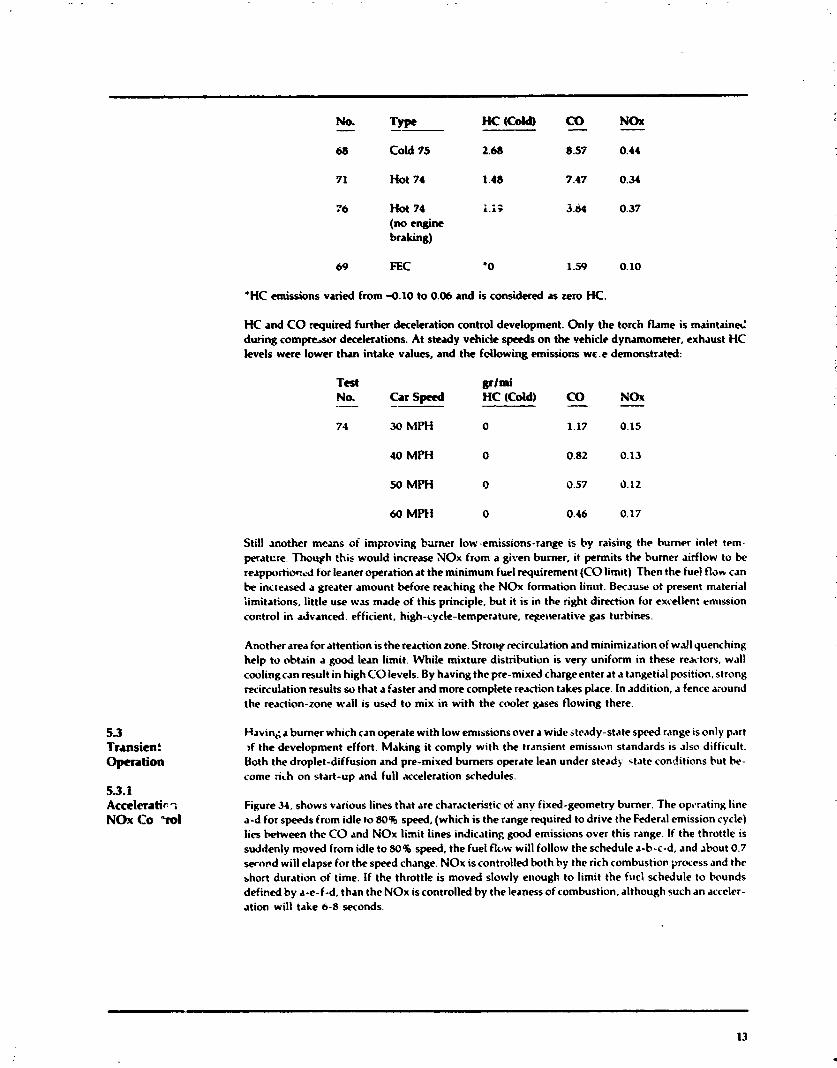
No. - TJ- Hc(C0M) CO - NOX -
5 3 Transient Operation
68 Cold 75 2.66 8.57 0.44
71 Hot 74 1.48 7.47 0.34
76 Hot 74 i.i; 3 .h 0.37
(no engine bralting)
69 FEC '0 1.59 0.10
'HC emissions varied from 4.10 to 0.06 and is considered as zero HC.
HC and CO required further deceleration control development. Only the torch flame is maintain& during c c m p r e a r decelerations. At steady vehicle speeds on the vehicle dynamometer, exhaust HC levels were lower than intake values, and the following emissions wc.e demonstrated:
Test p i m i No. Car S p e d -- -- HC (Cdd) CO - NOx - 71 30 MPH 0 1.17 0.15
40 MPH 0 0.82 0.13
50 MPfi 0 0.57 0.12
Still another means of inaproving bdrner low-emissions-range is by raising the burner inlet trm- peratcre. Though this would increase NOx from a given burner, it permits the burner airflow to be r e a p p r t i o c ~ d for leaner operation at the minimum fuel requirement (CO limit) Then the fuel fldn can he increased a greater amount before reaching the NOr formation linirt. Bec~ujc of present material :imitations, little use was made of this principle, but it is in the right direction for excellen: emission coctrol in advanced, efficient. high-cycle-temperature. regenerative gas turbines.
Another area for attention is the reaction zone. Strorty recirculation and minimization of wall quenching help to obtain a good lean limit. While mixture distribution is very uniform in these reactors, wall cooling can result in high CO levels. By having the pre-mixed charge enter at a tangetial position. strong recirculation results so that a faster and more complete reaction takes place. In addition, a fence around the reaction-zone wall is used to mix in with the cooler gases flowing there.
H a v i n ~ a burner which can operate with low emissions over a wide steady-state speed range is only part ,f the development effort. Making it comply with the transient erniss~on standards is also difficult. Both the droplet-diffusion and pre-mixed burners operate lean under steady state conditions but he- come &h on start-up and full acceleration schedules.
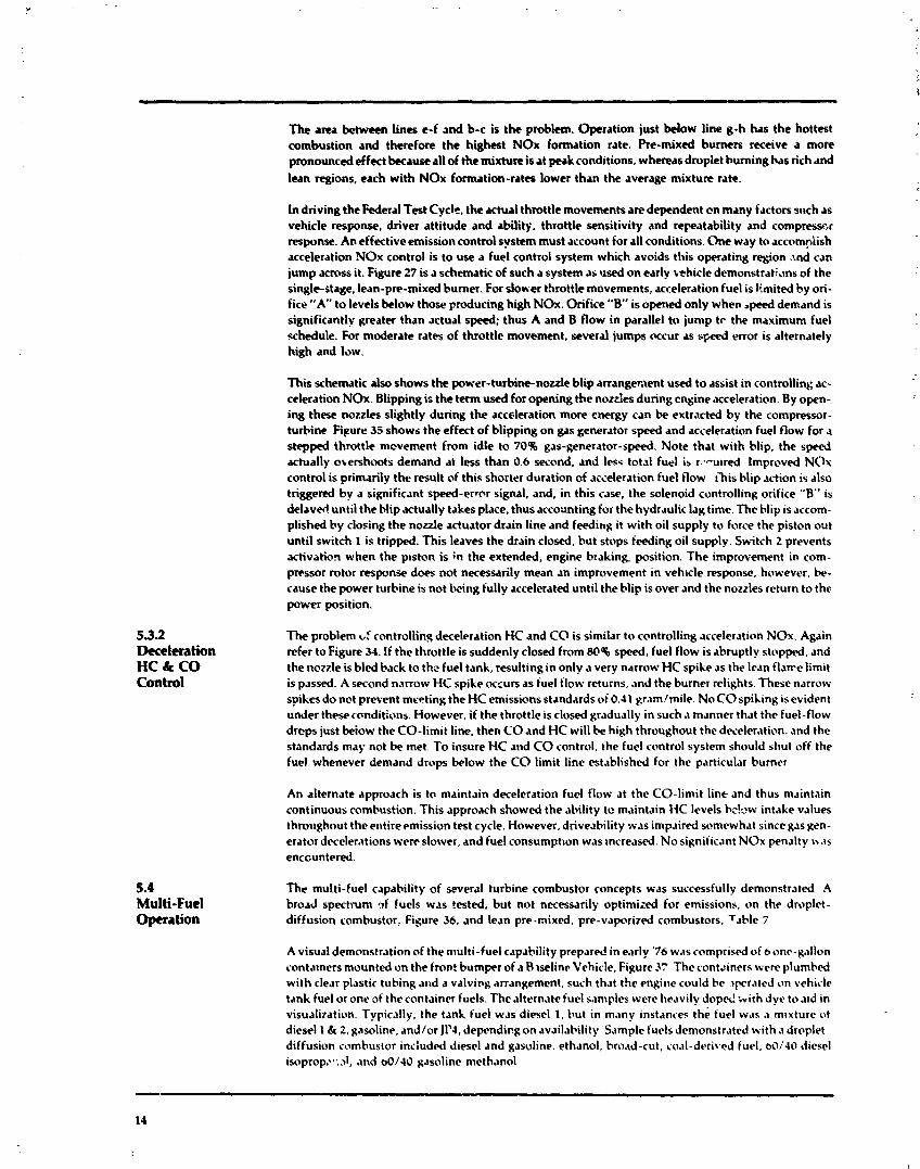
Figure 34, shows various lines that are characteristic of any fixed-geometry burner. The opt*r.iting line a-d for speeds from idle to 801 speed, (which is the range required to drive the Federal emission cycle) lies k t w e e n the CO and NOx limit lines indicating good emissions over this range. If the throttle is suddenly moved from idle to 80% speed, the fuel flow will follow the schedule a-b-c-d, and ibout 0.7 wand will elapse for the speed change. NOx is controlled both by the rich combustion process and the short duration of time. If the throttle is moved slowly etiough to limit the fucl schedule to hwnds defined by a-c-f-d, than the NOx iscontrolled by the leaness of combustion. although such an acccler- ation will take 6-8 seconds.
5.3.2 Deceleration HC & CO Control
5.4 Multi-Fuel Opera tion
The area between lines e-f and b-c is the problem. Operation just below line g-h has the hottest combustion and therefore the highest NO* formation rate. Pre-mixed burners receive a more pronounced effect because all of the mixture is at peak conditions, whereas droplet burning has rich and lean regions, each with NOx formation-rates lower than the average mixture rate.
In driving the Federal Test Cycle, the actual throttle movements are dependent c n many factors sr~ch as vehicle response, driver attitude and ability, throttle sensitivity and repeatability and cornpresscr response. An effective emission control system must account for all conditions. One way to accompiish acceleration NOx control is to use a fuel control system which avoids this operating region .l.nd can jump across it. Figure 27 is a schematic of such a system as used on early whicle d e m o n s t r a ~ ~ n s of the single-stage, lean-pre-mixed bumer. For doh-er throttle movements, acceleration fuel is limited by ori- fice "A" t o levels below those producing high NOx. Orifice "B" is opexted only when .peed demand is significantlv greater than actual speed; thus A and B flow in parallel to jump to the maximun~ fuel schedule. For moderate rates of throttle movement, several jumps occur as speed error is alternately high and low.
This schematic also shows the power-turbine-nozzle blip arrangement used to assist in controlling ac- celeration NOx. Blipping is the tenn used for opening the nozdes during engine acceleration. By o p n - ing these n o d e s slightly during the acceleration more energy can be extracted by the compressor- turbine Fipure 35 shows the effect of blipping on gas generator speed and acceleration fuel flow for a stepped throttle mcvement from idle to 70% gas-generator-speed. Note that with blip, the speed actually mershoots demand at less than 0.6 second. and less total fuel is r--u~red Impmved NOx control is primarily the result of this shorter duration of ~cceleration fuel flow ihis blip action is also triggered by a significant speed-error signal, and, in this case, the solenoid controlling orifice "B" is de lavd untii the blip actually takes place, thus accounting for the hydraulic lag time. The blip is accom- plished by closing the nozzle actuator drain line and feeding it with oil supply to force the piston out until switch 1 is tripped. This leaves the drain closed. but stops feeding oil supply. Switch 2 prevents activation when the p~ston is in the extended, engine braking position. The improvement in com- pressor rotor response does not necessarily mean an improvement in vehrcle response, however, k- cause the power turbine is not Lwing tully accelerated until the blip is over and the nozzles return to the power position.
The problem U' controliin~ decel~ration HC and C O is similar tcr controlling acceleration NOx. Again refer to Figure 34. If the throttle is suddenly closed from S@% speed, fuel flow is ahmptly stopped. and the nozzle is bled back to th? fuel tank, resultingin only a very narrow HC spike rs the lean f1an.e limit is passed. .4 second n.lrrow HC spike cxzurs as fuel flow returns, .lnd the bumer relights. These narrow spikes do not prevent meeting the HC emissions standards ot 0.41 grim/mile. No C O spiking is evident under these conditions. However. if the throttle is closed gradually in such .I manner that the fuel-flow drcps just beiow the CO-limit line. then CO and HC will be high throughout the dweler.rtion. and the standards may not be met. To insure HC and C O control. the fuel control system should shut off the fuel whenever demand drops below the CO limit line established for the particular burner
An alternate approach is to nraintain deceleration fuel flow at the CO-limit line and thus maintain continuous combustion. This appro.ich showed the ability to maintain HC levels hc!ow intake values throrrghout the entireemission test cycle. However, driveability was impaired somewhat since gas Ken- erator decelerations were slower, and fuel consumpt~on was rncreased. No signiiicant NOx penalty \\ .IS
enccuntered.
The multi-fuel capability of several turbine combustor concepts was successfully demonstrated A broad spectrum qf fuels was tested. but not necessarily optinrixd for emissions, on the droplet- diffusion combustor, Figure 36. and lean pre-mixed, pre-vaporized combustors, Table 7
A visual demonstration of the multi-fuel c.rpability prepared in early '76 wrs comprised of o one-gallon coritalners mounted on the fron! bumper of a Blseline Vehicle, Figure 3 3 h e containers were plumbed with clear plastic tubing and a valvisg arrangement, such that the engine could be ,prated on vehicle tank fuel or one of the container furls. T h e alternate fuel srmples were heavily d o p d k i th dye to a ~ d in visualitation. Typically, the t ~ n h fuel was diesel 1. Put in m.rnv instances the fuel w.rs .I mlxturc ot diesel 1 & 2, g.isoline. and/or JI'I, dependingon ,~vailat.ility S.rn~plc fuels demonstrattd with J droplet diffusion comhusior included diesel rnd gasoline. eth.~nol, bro'id-cut, ro.11-derit.4 fuel. bOt'4O diesel isopropz-:A, and &/I0 gasoline methanol

5 5 Odor Evaluation
5.6 Prossure-Drop Effects
5.7 Combwtor Materials
Continuing development of the pre-mixed/pre-vaporized combustor concept in a test-cell engine with alternate fuels exhibited similar results. Table 7 shows the results of steady-state idle speed anc! typical idle-to-70%-speed acceleration experienced during an urban-cycle test. The only adjustment made during these tests was to the torch to maintain it at stoichiometric conditions. The coal-derived fue! obtained from pyrolysis resulted in high NOx levels that were attributed to the level of chemically bonded nitrogen. Fuel containing a high content of sulfur, ash, residue and/or bonded nitrogen will require further processing to make it acceptable for turbine uw.
During the course of engine development, a major deficiency consistently identified was that ot exhaust odor during cold starting, particularly when usin,: a lower-grade diesel fuel (high sulfur content). In an effort to characterize exhaust odor on the advanced burner concepts. an engine was assembled on a portable test stand and equippea with a self- contained multi-fuel system. This would provide the flexibility to pennit cold-starting the engine a, vanous ambient temperatures down to -20-F.
After prelimirary work was concluded, an advanced prr-mixedlpre-vaporized combuster was installed, and an attempt was made to associate the presence of rdor with HC generated from gasoline fuel duringa cold start (70.F). (Diesel furl was not to be used with the LA', regenerator cores installed in this engine). However, odor levels were minimal and certainlv not >tjec:innable. Since the prob!em did not appear to be critical, the cold-start/odor evaluation was terminated to permit higher priorrtv work to proreed.
The pressure-loss across the combustor is very important to low-pressure, automotive gas turbines. especially at low power levels. Figure 38 shows thtt a given engine looses power and sdters an increase of specific fuel consumption with increasir~g pmsure-drop. As pressure-dro;, is -educed, SFC and engine size are reduced at a given power :evel. Pressure drops greater than 3% should not be considered for automotive use. The burner of the Baseline Engine has approximately 2% pressure-drop. !n order to use variable-geometry burners and maintain very low pressure-draps, 8~0th primary and dilution zones may need to be varied. such as was implemented on the Solar burner.
.9 limited effort was made to evaluate ceramic components in combustc. Fystems. Two silicon-nitride burner-tubes were run with the burner configuration of the Baseline Enp'ne. One silicon-carbido-coat- ed-graphitr: first-stage reactur tube was evalu~ted with the duaI-stP1 e concept. All test c;mples develop4 cr~cks after short running times. Such applications are .jesir~t.Ie because of lower weight, thermal ~nertia, and potentially low cost.
40 CERAMIC REGENERATORS
6.2 Conversion to Ceramic Regenerators
Metallic regenerators were developed and tested for several years prior to their use in the Baseline Engine. Maximunl durability excceded 3000 hours in an endurance engine. The concept of a ceramic regenerator, however, otfers potential advantages in a number of areas, and, since the design of the Baseline Engine, substantial progress in the area of ceramic regenerator technology has been made. Spe- cific areas of potential advantage are:
1. Improved engine efficiency by allowing increased engine operating temperature.
2. Lighter weight - approximately one-half that of a metal regenerator.
3. Higher effectiveness at low flow rates, due to lower axial heat conduction.
4. Simpler sealing because of low thermal distortion.
5. Potentially lower cost due to the use of non-critical materials.
Some original work was ysformed in this field as earlv as 1960. These tests : .ere confined to a regenerator fixture, and the matrices of that time showed deficiencies of a technological and material nature. Thiiner, stronger stock and finer, more uniform passages were required. These preliminary studies indicated that ceramic regenerators would satisfy the automotive gas turbine requirement if satisfactory technological progress could be made. This, of course, would inoiive development, not only of matrix material and shape, but also of suitable drive, suspension, and sealing systems.
During the late 1960's and early 1970's, ceramic regenerator work was deferred pending development of a reliable design by the ceramics industry. By 1973, such designs were readily available, and the task of converting the Baseline Engine was begu.1.
When the decision was made to convert the Baseline Engine from metallic to ceramic regenerators, several basic guidelines were established:
1. The ceramic regenerators should fit in the existing envelope with a minimum of mechanical changes.
2. Seals, drive-gear, and other related components should closely follow the established, trouble-free designs proven in the Baseline Engine.
3. The conversion should take place with a minimum of delay, necessitating the use of off-the-shelf core and seal materials.
6.2.1 Comparison of theoretical performance among several versions of available ceramic matrices and the Matrix Selection current metal regenerator indicated that, for the same size and pressure-drop, the ceramic cb.? should
be superior to the metal core at idle and part-throttle conditions. The best overall performance should be from a ceramic matrix with rectangular passages. Results of this study are shown on Figure. 39.
On the basis of the above comparison, specifications were drawn and discussed with prospective ven- dors. Ceramic technology at the time was not capable of producing a rectangular matrix, but two alternate types were proposed:
Type "A", a wound triangular or "sine wave" shape,
Type " B , nested giass tubes forming a hexagonal shape.
Samples of currently-available matrices of both types were inspected for pressure-drop, and the final selection of each type of matrix was based on its closeness of match to the Baseline Engine's pressure- drop. Since envelope constraints required use of the same overall diameter as the metallic regenerator, matrix thickness was adjusted as neLessary to corrwt the preswre-drop. Final matrix designs selected are shown on Table 8. Baseline metallic matrix specifications are shown for comparison.
6.2.2 Several ceramic cores of each type were procured, inspected, and fixture-tested prior to installation in Rqenerator the engines. Inspection procedures were patterned after those developed for metal regenerators. Procurement and Preliminary screening for acceptable pressure-drop was carried out with the cold-flow fixture shown in Inspection Figure 40. Metered air was introduced t o a known area of the matrix and allowed to exhaust to atmo-
sphere. Using the pressure, temperature, and flow conditions in the flow cup, the pressure-drop under engine operating conditions was calculated from Figure 41. These data were used, not only for core acceptance, but also for ensuring that each engine was fitted with a matched set of cores.
Following flow check, a leak-test fixture was used to check for porosity and internal voids. A cylindrical volume of matrix was sealed at each side of thecore and pressurized. A flow-meter measured the make- up air required to maintain pressure. Each regenerator was then dimensionally checked, with particular emphasib on surface flatness. Close-xip photographs of the matrix were taken for computer-aided graphical analysis of passage geometry.
Finally, each regenerator was fitted with a ring-gear and tested in the regenerator fixture This fixture was designed to match, as closely as possible, actual engine conditions. Compressed air was first heated to sin~ulate the required compressor-discharge temperature and then passed through the high-pressure side of the matrix, where it picked u p additional heat. The air was then throttled to simulate the pressure-drop across the turbines and heated to a fixture-limited inlet-temperature of 1290°F. The hot air then passed through the low-pressure slde of the matrix. where it gavc ..p much of its heat before k i n g exhausted to atmosphere. A variable-speed external drive .system was used to rotate the regenerator, and drive speed and torque were monitored to evaluate the seal coefficient of friction. Standard ASME metering orifices were used to check airflows throughout the fixture, permitting accu-
- rate measurement of seal leakage. Temperatures were recorded by means of thermocouple grids near both faces of the matrix, and effectiveness was calculated and corrected, through a computer program, for actual engine conditions of 1350.F at the inlet to the low-pressure side.
6.2.3 Drive System
6.2.4 Seal System
Drive and suspension methods are similar to metallic regeneratc - mctice. Optimum seal performance requires freedom of matrix movement in all directions except tially. To achieve this freedom, the spherical, graphite bearing of the metal core was replaced by an elliptical, graphite sleeve, which was designed to slide In a cylindrical bore in the ceramic hub. The core was rim-driven using a drive-pinion and ring-gear Identical to those used with metal cores. Past experience with a variety of suspension and drive systenls demonstrated the superiority of the cenLer-support-rim-drive concept with metal cores, and this method worked equally well with ceramic cores
Two different methods of attaching the metal ring-gear to the ceramic-matrix rim were trled
1. Mechanical mounting was used successfully with early Type "A" matrices. This method utilizes solid ceramic drive-pins cemented in the matrix rim; these pins were engaged by spring.-loaded metal drive-shoes suspended from the gear and rim. This method had the best life potential at extreme temperatures, but the cost penalty was grezter, and acceptable gear runouts were difficult to achieve
2. Elastomeric mounting, now the preferred method, was accomplished by flxturing the gear a i ~ d its rim concentric with the matrix and injecting silicone rubber into the annular space 'etween them This method was more economical, and accurate ring-gear runouts of less than 0 01" were typical However, careful design wa:, required to keep the elastomer temperature below 550'F k:are detalled information on elastomer potential is given under "Elastomeric Drive I3evclopnicnt." below. Figure 42 illustrates a typical elastomeric mount.
In keeping with the conversion guidelines, standard diaphragm-type baseplates were used for both inner and outer seals, as shown in Figure 43. Inner rim and outer "D" rubbing sc'~ls are high-tem peratlire graphite from the metallic regenerator assembly, and only the crossarm-seal coating was
changed to achieve compatibility with the ceramic matrix The coating selected contained 85% nlchel oxide and IS% calc~um fluoride, this was the best available m.1tcri'd at that time This coating h.15 the adva~rtages oi low coett~cient of friction (0.2) and extremely lov wear-rate (theoretical codtin,: 11fc = 4U.000 hours), but alleged heath hazards attributed to nickel compoundsdictated thenecd for the cvcn- tual repl,~cenierrt of the nickel oxide. The prograni to perfect a suitable substitute is discussed under "Seal Coating t>evelopment," below
6.23 Five of the Baseline Engines, fitted with ceramic regenerators of both matrix types, were endurance- s ~ - tested for over 2200 huurs under the severe accelerated wear and the& shock test cycle. As shorn on P c r f a n r ~ n ~ ~ Fig. 13, the cycle alternately subjects the matrix to 14WgF at high-power conditions, followed by rapid
cool-down to 9WF at idk. The thernul transients in this test sequence are far more extreme than any anticipated in the vehicular duty cyde and were d-ed to screen various matrix configurations for susceptibility to themul fatigue cracking. A 60% -to-100% -speed acceleration was included to subject the elastomeric core/ring-gear attachment system to high-torque conditions. The engine was sub- sequently modified to have the regenerator cores driven directly from the power turbine reduction gearing to simulate the free-rotor concept to be used in the Upgraded Engine. This drive arrangement resulted in a more severe mtrix-temperature-padient under conditions of cold-engine stan -up, fol- lowed by a rapid demand for power.
All of the regenerators performed well under the 1400.F-cycle, with 581 cycles logged on Type "A" cores and 521 on Type " B . The only difficulty experienced was with the two "Thinwall," Type "A" regenerators; both show3 failure of the outer-most matrix layer under the elastomer pads after 9 cy- cles. Following repair and rebuild with increased flexibility in the elastomeric mount, discussed below under "Elastomeric Drive Development," each core completed 472 additional cycles without incident before the end of the Baseline Engine program.
6.2.6 scal coating Development
As disc!-tsed abave, concern had been expressed over the use of nickel oxide as a seal-coating material because of the alleged health hazard of nickel compounds. While the amount of nickel oxide in the Baseline Engine's exhaust was extremely small (on the order of Ipg/mJ) basic research was carried out in the area of seal coatings to seek an acceptable substitute. A number of potential materials were tested, as listed in Table 9. Fixture testing consisted of rotating a small matrix sample against a simuiated seal in an electrically heated furnace. Rubbing speed, seal load, and operating temperature were set to match any anticipated engine condition, and drive torque was continuously recorded. Figure 44 shows the results of several of these tests, and illustrates the lower coefficient of friction of the Type "A" matrix as compared to the type "B", regardless of the coating used. This phenomenon was verified on a fixture test of full-sized regenerators, where typical drive torque of 70 Ib-ft (Type "A" matrix) compares to 90 Ib-ft for Type " B . It is believed that this discrepency results from the basic design of the matrix. The nested glass tubes are less porous than the wound ceramic, and the calcium fluoride, which acts as a dry lubricant, is less readily embedded in the glass.
Only one advanced coating (calcia-stabilized zirconia) was engine-tested. Wear-rate was considerably higher than with nickel oxide, as shown on Table 10, but the projected life of 2300 hours is still quite adequate for a development program. However, the higher required torque (11.3 Ib-ft) produced exces- sive gear wear.
6.2.7 All ceramic regenerators were eventually converted to the elastomeric mounting concept. During Elastomeric developn~ent of this method, a number of regenerators exhibited small areas of cohesive failure of the Drive Development elastomer. These tears originated at stress risers such as bubbles in the elastomer surface, and enlarged
very slowly over a period of several hundred test hours, until the mount was deemed unsafe for further running and replaced. These failures are believed to be caused by a gradual shrinkage of the material over an extended period at high temperattire. A comprehensive program was established to fully docu- ment changes of properties with heating.
Several alternate elastomers were evaluated, but they all showed lower properties (plrticularly in the area of tear strength) than the Dow-Coming Sylgard 187. Samples of Syl~ard 187 showed no appre- ciable change in elastic or shear moduli after 300 hours at 500'F, indicating that, once initial shrinkage is allowed for, this material should function well in the Upgraded Engine environment.
To compensate for elastomer shrinkage, a flexible maunt, as shown on Figure 45, was developed. This design permitted relatively free radial movement of the elastomer to allow for thermal expansion, while still retaining sufficient axial and circumferential rigidity to transmit the drive torque. As discussed rhve . the flexible mount was extensively tested in the endurance engine and remained trouble-free throughout the balance of the program. It should be noted at this point that the basic concept of this mount is a sound one. To verify the integrity of the design, a mount was statically tested to failure using the arrangement shown on Figure 46. Gradually increasing torque was applied to the drive pinion, and ring gear deflections were noted. The mount sustained a load of 720 Ib-ft, as contrasted to ,I typical maximum torque of 70 lb-ft.
6.2.8 Rqenera tor Drive Torque Study
63 Improved- Effectiveness Matrix Development
6.4 Ceramic Regenera tor Thermal Analysis
Much of the success of the flexible mount was undoubtedly due to the remdrkably low drive-torque requirements inherent in the pressure-balanced seal design. To verify that drive torque does not increase with running time, a high-time (300 + hours) Vendor-A-core and nickel oxide crossarm were tested in the regenerator fixture. l 'he test showed that the glaze build-upon the matrix surface reduced the drive torque by an average of 35%, with torque at 100% dropping from 81 Ib-ft. to 53 Ib-ft.
To further study the effect of operating conditions on regenerator torque, an in-line torquemeter wds installed in the core-drive system of the endurance engine. Torque was measured over a wide range of engine conditions, with results as shown on Figure 47. It was found that the torque with the nickel oxide crossann was unchanged over a temperature range of 1000-1400'F and was only slightly dependent on speed. As expected, the major influence on torque was compressor discharge pressure, which provides most of the force that clamps the seal elements to the matrix. Since these cores had 200+ hours at the time of the evaluation, overall torque was correspondingly low, i.e., 56 Ib-ft at 100% - speed conditions. O n the Baseline Engine, therefore, the maximum power requirement to drive both regenerators was less than 0.5 horsepower.
Once the feasibility of operating the ceramic regenerators in the Baseline Englne wds proven, the next step was to test matrices of increasingly higher effectiveness and to actually demonstrate the performance improvement shown possible by the theoretical studies illustrated in Figure 39. As shown on Figure 48, 1% increase in regenerator effectiveness results in a 3% reduction in idle fuel consumption. For this part of the program, it was decided to work with Type "A" matrix, in view of its prover. lower torque requirements and potential for the greatest reduction in wall thickness. Several cores were tested with increas~ngly thinner walls and smaller hydraulic diameters, to the limit of the vendor's tooling capability. New tooling was made on the basis of the earlier test results, and the final set of cores achieved the program goals of 0.003-in. wall thickness, 0.020-in. hydraulic diameter, and 76% open area.
The fixture test results are shown on Figure 49A. The Upgraued Engine pressure-drop scaled to the Baseline Engine size, was 32 in. HzO, - somewhat higher th.17 the Baseline Engine design value of 24 inches and resulting in a power loss of 8 HP. It can be seen that . ile Upgraded Engine would have a lower airflow per unit matrix area, and the resulting pressure drop would reduce to the dcsign value of the Baseline Engine. At these low specific airflows, the effectiveness of the ceramic matrix shows the great- est imprcvement over the metallic type. The gain in engine fuel economy is substantial as shown on Figure 498. The advantage in effectiveness, combined with the benefits from higher cycle temperature made possible by the ceramic matrix, show the ceramic regenerator to be a strong contender among potential automotive turbine heat exchangers.
In a free rotor engine, the regenerator matrix temperature can increase substantially withln a few sec- onds, while the relatively massive solid hub and the matrix rim which is protected by the seal remain near their initial temperatures. This can result in significant circumferential temperature gradients as well as larger radial and axial gradients than for a regenerator which is driven by the gas generator where there is reasonably close coupling between the regenerator speed and the engine air flow Thus, a thermal analysis for this severe condition, a cold start quickly followed by a full acceleration, was conducted in support of the mechanical design of the regenerator
The matrix was divided into 36 pie shaped sectors and 10 thicknesses as shown in Figure 50A The figure shown represents a grid fixed in space with the matrix rotating through it. Therefore, 'at any instant of time the matrix material in sector "S" will be the hottest and that in sector "A'' the coolest Figure SOB illustrates the temperature throughout the matrix after one quarter revolution from .I cold start. The lettered and numbered points are consistent with the Figure 50A sector notation At this particular instant, some of the sectors have not passed under the crossarm seal dnd therefore stlow identical temperature gradients. All of the other sectors have different gradients because they have passed under the crossarm seal and have been exposed to gas flow from both T8 and 1 3 for v'arlnus lengths of time. When the temperature of more than one sector is idrniical only the higher letter or number was printed. Figcre 50C shaws the potential thermal deformation of the elements at t h ~ s same instant for a material with the thermal expansion charactt~istir shown in Figure SOA T h ~ s is an LAS material developed by Vendor A.
Figures SOD, E and F are plus .sf I-dculated steady state temperatures for the same air flow, but with different speeds. They show t h ~ t for a core whch is rotating fast relative to the air flow, the circum- ferential temperature gradient wuuld be small and a structural analysis assuming no circumferential gradient would therefore be adequate. On the other hand, for a core which is rotating slowly relative to the air flow, which would be possible witit a e rotor engine, the circumferential temperature variation can be significant.
7.0 ENGINE CONTROLS
7.1 Baseline Hydromechanical Control
7.2 Electronic Control System
The Baseline Engine was equipped with hydromechanical controls lor fuel metering and power- turbine-nozzle actuation. Additionally, a relay-type start- safety protection packdgc was utilized which incorporated electrottic over-temperature and light-oft detection.
The fuel control provided the functions of steady-state gas-generator-speed governing, start/acceler- ation fuel schedulingand fuelshut-off on decelerations. As shown in Figure 51, the fuel control, drivon by the gas generator, consists of a positive displaccmrnt pump, a pressure regulator, flyweight gover- nor, an acceleration orifice and an altitude compensator. Stari/acceleration fuel is scheduled as a func- tion of compressor discharge pressure with altitude trim. Schedule changes were accomplished by ori- fice sizing.
The power-turbine-nozzle actuator, supplied with engine oil pressure, was a hydraulic positioner which provided modulation of the nozzles in accordance with a cam-generated schedule based on turbine exhaust temperature. This actuator also provided 3 fixed braking oosition of the power turbine nozzles for vehicle braking. Also shown in Figure 51 is the hydraulic circ~i ; :;;: t5e nozzle actuator Transmission governor pressure is utilized (through a transfer valve) to p r~vide a bri.t.i.?~ signal to the actuator. With vehicle speed above 1 5 mph and the input arm of the ;ctuator : " ,dle poyition, full line-pressure is applied to the back of the piston to extend it to the t raking : A two-pocition idle is accomplished with an idle positioner to accommodate increased ac~es. ?ing, specificali? the air conditioning compressor load.
In add i t i~n to the hydromechanical fuel control and power-turbine-nozzle actuator, tile gas t u r b i ~ e engine requires a s.lfety system. This start-safety system provides automatic start-sequencing upon initiation of the key sv.ritch. A no-start condition results if the transmission is not in the start 'park position. There are four starting mode aborts as follows:
Failure of the burner to light within 8 seconds. A lightoff constitutes a 100'F/sec. rise on turbine inlet temperature. Failure to reach 25 PSI oil pressure within 5 seconds. An overtemperature (turbine inlet temperature equal to 2000°F) for 2 seconds duration. Cranking time in excess of 20 seconds.
A restart can be made in the latter three cases, however, if the burner does not light, a 311-second-reset time is required to allow fuel to drain before restarting. The start safety-system logic is shown in Figure 52.
These hydromechanical controls are simple, reliable and low in cost; however, they are deficient in the following areas:
1. No allowance for ambient temperature compensation, power limiting or speed correction.
2. Turbine exhaust temperature is based on a crm-generated average-temperature schedule instead of actual temperatlrre. This does not allow optimum economy, emissions and performance due to variations in ambient temperature, engine leakage, engine conditions, et cetera.
3. Adaptations of the hydromechanical controls for idle-speed control and nozzle opening (or "blipping") on gas generator acceleration requires complex additions such as linkage, solenoid valves, etc. ~ n d has resulted in performat~ce less than optimum.
Additionally, the control demands of the Upgraded Engine--i.e.. free-rotor gas generator, variable inlet guide vanes, water injection and low-emissions combustor-require increased control complexity. Desigr~ and development of an integrated engine control system was therefore undertaken to investigate whether and to what extent these def1c;encies could bc overcome and new control requirements satisfied in a cost-effective manner. This activity is reported in further detail in Reference 3 and 4.
This electronic dpproach was selected to provide flexibility in the developmcnt stage with findl i~~iplernentation dependent on the requirements. As shown in Reference 5, present electro ~ i c controllers, being ot a developmental nature, are either hald-wired or printed-circuit-board with discreto components Considerations toward extending electronic control concepts and f~rnctions to high-vo~ame production include L," (large scale integraticn) technology, microprocessors and digital implement.: tion.
A list of engine .,nd control-system parameters is shown on Table 11, and a simplified block diagram of the electronic con~rol system is represented by Figure 53.
The functions of the v-rious control loops are list. ;l below.
1. Fuel Cont~ol
Gas-generator-speed governing based on ambient correction.
Start/acceleration fuel scheduling as a function of corrected gas generator speed with thc start schedule altered by power turbine exhaust temperature. Fuel shct-off on decelerations. Turbine-inlet-temperature limiting during starting and accelerations. Maximum-speed limiting for gas generator rotor and outnut shaft Output shaft idle-speed governing in cnnjuncrtion w'th either the pow .r turbine nozzles or inlet guide vanes.
2. Nozzle Cuntrol
Power-turbine-exhaust tempe: ature contra1 in power and braking modes Engine braking. Qutput shaft idlr-speed go\rcrning. Open nozzles for start and acceleration modes Open nozzles for loss of temperature sensors at turbine inlet or exit
3. Inlet Guide V.~ne Control
Low -speed power modulation. Output sh.~f! idle-speed governlnq
e I'ower augmentation at maximum g.1~ generator speed
4 M1.tter Injection
a Power augmentation
5. Start-Stop Logic
The sarlie functions of the Baseline Engine package werc incorporated in MOS (m-t.11 oxldt. srml conductor) digital lngic
o Diagnostics
The electronic control system incorporates a diagnostic connector with 55 test poi !ts tc) rv,~lu.~tc. engine and control system performance Test points in-lude cond~tinncd arid unconditi~\ned scnhor inpui.s, computed schedules, logic commands and control system outputs
In conjunction with the c . .~lopment of the electronic control systc,ns, a computer s~mul.ltron nlcrrlcl ot the Baseline Engine was constructed and utilized to assist in control cc~lcept dct,ni!ion and c\,~Iu.lt~on of steady-state and transient characterist~cs. The engine model WAS effective In Icflnlng loi~p g.ilns and stabilizing terms; however, some schcdulc changes wcrc necessarv during e ~ g i n e . ...I vehi~lc t r s t~ag ~ L J
improve driveability and surge-free operation
he electrunic controller was Ladgud with *t wired circuit boards using arulog -try for control functions and digital logic for stating and engine prok;ion. P u W output st- were utiliad
htd for the actuators and variabk-speed fud-pump motor. Various circuit modifications weie q u i d Implementation during early operation and involved such ptoblans as power-supply operation at low volt-, stabk
low-speed openliond the fuel-pumpmdorhrld noiseinterferences with t h e m (transistor-transistor logic) start logic. Other p d e m s emmmtered were internal wuing co~ections as well as harness amnections. Figure 54 Saws the electronic controller in the test cell along with cabation equipment and instnunenhtion fcr diagnosLic pupas 5. Fig. lie S i -iiows the contrcfler as it was mounted in the trunk of the vehide. The test cell inshllatmrr id p.qmmmble arulog conhuller is shown in Figure 56. .\ vehide module is contained in the Rcic-mounkd cdigumtion located on top of the pin- programrmMe read-only memory unit. Thjs system utilizes analog sensor and output stages and performs compuhtbm sequentially in ;KxwdancP with a dodtconb.dled digital software program.
The fuel metering was accomplished by a vuiabk-speed, constant-displacement pump. Fuel flow was -red as a dosed-loop function of pump speed. Fuel flows ranged from 5-160 PPH, and the pump was turned o!f on gas generator decelerations. Later, with the combustor torch igniter requiring continuous fuel flow, a constant-speed fuel pump was utilized with a proportional metering valve and volumetric flow sensor.
Speed, position, tenlrl'rature, flow and pmsure sensors were utilized with the electronic control sys- tem. Speed signals were sensed with magnetic pick-ups, turbine inlet and exit temperatures were sensed with thermwouples and ambient temperature was sensed by a resistance sensor. Positions of the throttle-pedal, variabie power turbine nozzles, and variable inlet guide vanes were sensed with Pnear potentiorneten; a:r.tlrlb pwsure was sensed with a LVDT (hea r variable differentid transformer) diaphragm transducer. Fuel flow was sensed with a paddle-wheel flow-sensor. Some test activity was prfemed on fluidic temperature sensors. The most successful unit tested on this program was provided by AiResearch/Phoenix. The vendor has thoroughly tested the sensor in regard to problems experienced with previous units, such as response and waveshape distortion. A description of operation of this fluidic temperature sensor it was tested follows.
The fluidic turbine-exit gas-temperature sensor operated on the principle of detecting tlle change in the speed of ound as local temperature changes. The sensor consisted of a digital fluidic amplifier whose control jets were interconnected by a temperature-sensing tube. The tube transported a low-pressure pulse of air generated by the power supply and aspirated the control jets as the amplifier was supplied with air. The trarsport of this pulse through the tube occured at the speed of sound, which is a direct function of temperature. Upon reaching the opposite end of the tube, the pulse had sufficient energy to cause the power jet to switch from one side of the amplifier to the opposite side. This switching cycle repeated, and an output frequency was generated which was directly related to the delay time of the pulse traveling through the tube at the speed of round. As temperature increased the frequency output increased.
n i s pneumatic frequency output was applied to a pietoceramic disc that transduced the signal to an electrical frequency which was directly applicable as an input to either analog or digital electronic control systems.
The fluidic sensor operated with a supply pressure of 3 psig, and had a time constant 0.9 to 1.7 seconds. The frequency output was a function of absolute gas temperature as follows:
where f = frequency in Hertz, K = constant, and T = temperature in 'R.
A tempctature-to-frequency calibration was made on the Baseline Engine by means of a three-thermo- couple rake with 28-gauge chrome1 alumcl couples in the power turbine exhaust. Figure 57 shows this calibration taken at gas generat? -eds from idle to 70 percent a7d propshaft speeds from 900 to 2000 rprn. The sensor output wdvesh,., contained harmonics; therefore ? zero-crossing saturation amplifier
was utilized for pulse shaping. Transient data utilizing 1.5 second l e d crr~npcnsation is shown in Fig- urtx -58, 50. and h0 for a start. acwleratit~n and Jhderat ion, rrspectivcly. This s m w r euhibih a in- qucnzv shift anlund =*F. which produced the pah ing shnwn in Figure =. Contnd rcjprnsc sprcifi- cations for the Upgrded Engine would require 4 substantial i m p n - r m n t in m p > n s e it the fluidic sensor wew to h- .t viable part id the iontrrd system, tlre s i x would have to tw r d u c d
7.6 Actuators
7.7 Electronic Enginc-Control Summay
The eltytnmiz iontrtbl systems ut i l i rd available rctuatcm. krr power-turbirz-nuzrlc aztuat t~~n, an elwtn>hydraulit actudtor prcrvidcri closed-liwp trim-contnd in crrniunction wtth the hvdronrtihaniial ~ i t u ~ t ~ l l :I thrtv- w.~y wlenoid valve w l ~ t t d the prwer or braking mode on the unit Tht. inlet-staide- vane xtuattw was an e\teradd-stnbkt* nrodifizatir~n 01 the dtitn~hvdraulic trint-actuator Thr c ~ ~ n r h l n d p~wer-turbine-:to?zIe-acturtor assembly is shnwn in h&uw 01 New .l<tll~tiWs were d r s i ~ c c t far the power iurbinr nozzles and inlet guide vrnzs on the Upgraded Fnsinc
In sumnratinn. t-lwtroniz ensine contml was rfftitive dnd was dentonstrrted on three vehiilt- The prilgranrnrablr analos zontrol with its caw of applicaticm and added tletrbility proved to be a valuable devrloptirtwt teal ttrr z t~ntnd work .IS nr t -nt i~~nrd III Rt-tert-nCe 4. All zclntrol r tyu in-nrrnts o t the ji.w turhlttt.tsnsinr wrrtb irrtt-gr.rttd into .I s i n p l r r l . ~ t ~ w i ~ zontr~d unit and w c ~ ~ c ~ p t i m i r t d ior pr i rrrm~ncc. eitmrlnlv .In4 cnrtsstrvls itvrtrrd .As nrcntiontd in Keiermic .% the sas turbint* cnsint- rtyutrt?; grpater control zonrplt*\tty whrn iatup.rrt4 with .I rtxtprtxat~ng t-nrine Further ampltiic~tion ai thc r.k-ntrol ~nrpIcmmt.~titm ts rt-qrrtrd .1lr111g wtth added devclopnrcnt of sensor tntcrtair rlrnlcrrtz Thr higher azquisttian <I8\' ot the tbit.itrorriz iontrol pck.t$e is only part o i thc rnort. :nrlwrt.tnt ti-t.?l rtisinr Itit.
cycle zost It 1s in this area r\.hrre zrrst eiietiveness can h. shown
a0 LOW-COSf TURBINE ROTORS
Two nenufwturing methods weme investigated for the purpose d dctemining their potrntirl of producing kw-cost. high wlume turbine mEoh: OM- method. which was p r q o d by the Pratt ud Whitmy Aircraft Corporation, was the hot. i so thcnr~ l forging prccrcss identified as CltcKiring The other method. which WJS pmposca by the AiRcserrch Casting Division of t h c G r r t Corpor~tkm, was a casting process urni.h is tuud on a mrsrMc pattern. The compressor-turbine of the B d i n Engine was u d as a nude1 to e v r l u t c t h e - pruc-esses Bcth companies nwe to provide sampler of t h c i ~ rrym-tive p e s r c wi:h the blrdc and disc s h a p of this rotor.
This prmss diffcn from previous hot isothmmd forgin$ methods in that 1 1 ~ temprature and f-y rate are controll~d either to produce a conditicm of suprphs t id ty in the n: <,rid k ing f a & . w tc maintain r cvndition of ulpwpbtirity in m*al previously plrcht in that t x d i t i m by s p - i r l proccssi~rl; b-hniqucr. This condition is esenlirlly fine wherein a mated, over a specific tmnper~hrn and strain rate tlcrw-: at a very ion. stress m d exhibris cstrrme duttilitg. Erpbiting the s u p r p l s t k state of the mterial allows forging d omapkx. tmntt\ureJ shaped rotors to ex tmndy close tdcranrrs. which s u b t m t h l l y reduces the input weight of the material required m d also d u r n machining c a t s In d d i t i ~ m , smailer. less-crxtiy forging equipment than that required tor conventional nickel tuse superalldv or titanium a l b y torging cur tx used.
l h c forged product prtdu.-ed by the G!orizins pnr;ez;s has two distinct advantages over a cast rutor Tk.? enhanced ductility, toughtress, m d cyclic capability inherent in a wn>ught pnduct s b l d sontnbutc tcr the reliability and durability of the smrll turbine enfi;?c %%tors. h forging also hasgrcrter ioasistrncv of part quality and greater freedom f n m internal defects than cast pmlucts
.4n inzmkiate problem for this p r o w s was the ribbing under the rim of the Basfine .ator Rihhing is n e c e s a ~ y in cast ro tos t c maintain intqr i ty k a u w rim cracking is entvuntcrd in low-cycle fatigue. To circumvent ihis, Pratt and Whitncy perwnnd p r o p 4 that r wlid disz b considered However. mersurenrents on material from thew forging prcxes indic.rtd much higher levels o i ductility than with castingmaterial. They, therefore. provided cr>mplcte sets of material propertics oi "C;ltc-:,d'' IN- I N from whic'r solid-disc designs wereex~mined The dat.1 iniludeif ultimate s t r e ~ r ~ t h . yield strength. and elongaticn JS turiitisms of tentpeaturn. Stress ruF:urt. and low-and high-cycle fatigue data were a lw su~pl ied
To invt3tigate the stn~c:ural p>tcntial at .I x81id disi. a two-dimcilsion.rl clasta-plasttc stress-~nalyns ia l~ i la t ion \\.as i l k i d into a computer prcsr,rrnr Tht. pr~\ tdurc tall:rrvrJ that outlinei i r r Reference 6
Ht~rvcver, a prc>blcn~ rel.lti4 to the stress-str.~in ctlrw a~):r~nimation was di.*-r\vc.rcd The hlansoc procdr~re rtyulres the t\luiv.~lent stress .lnd pI.rst;z strain to trp i d j u s t d to ~ t i s i y compatibility wl.ttinnxhip !n the i r ~ i o ~ ; %lose tk+ the yield p ~ i n t . sn~.rll in.rc.ur.~~it?; in :he stress-strain apprc~ximation curve <.In tar~se large diwrep.rncies in the pl.lstii sti.1111 whiih cr>uld prevent the program fmm convrrgln): on .I strrss-strain .point A R.imbtrrg Ospuld .rppro\inr.rt~on. .~djusttxi to wttcrstxt the yield point, w.1~ dscd with s.rtisf.rctctry resuits
In support of this program, El'A rcmtr~ctcJ with I ' .~ t t .rnd \Vhitney Aircratt Group, Government rrorfucts Division. to denranstrate the fcasil*ility cri l o w - i ~ + t proJuitit~n of ~ntqr.lll?; b lad t - auton~otivc turbine rotors The contrrct was zenduttcd in two phases The first yh.lse consistd of scuer.tl m.~ior task .lrc.rs .I h.~sii Imxrsb dcmonstr.rtlatr. prtKrss ~.rr.lmetc: c v ~ l u ~ t i v n . generation of design d.rta. detinition ot the manuf.rcturins scqri.-11.r. .and .I nr.rnuf.rcturing cost cstinr.rtr for IN- 100
Chrysler-tylr tompressor turbine rotors In Ph.lsc I1 the t..lpaEility :>t the forgins prwcss was ih.~rai- tcriztd as tc\ b:.~~fe sh.lpc, .11id the effeit of the bladr sh.rpe on B~scline Engine turbine rtttcirncy w.rs .~n.llytiially dcf~ntvi Mcdifted IN-792 .rnd AF?-[I).\ \ rc i~lvcsti);rted to determine their ab~lity tn
nrcct cngnne strength rcqutrrnlcnts R.~selinc F ~ ~ j i ~ i r r l i i i : \ i r t r ttttcvrs were su~.ccsstull j prcducd in AF2- 11>:\ hlodif~cd 1N-X: ritd not h.lvc ionsistcnt htsh t ~ r r ~ ~ r . ~ t r r : i - propcrtiea
To ev.rlt~.;!.- this protcss. tvhicl~ tratures .I rcr~s.~lllr p.rttrrn. :\iRrs~.rrifr C ~ s t ~ n f i I > I V I S I ~ > ~ w,... supp11ed w ~ t h the Ba~clinc Engine zon~prcssnr-tr~rbine-rot01 rv.1~ p.rttrrn tunling Thc m.rtrrr.rl sclrztrd W A S IN- 7Q2;tit l'his w.15 tlrc matcri.rl initt.~lly prarwsc~i i,lr usc rn thr Lipgr.ldrkl Eng~nc Jesipn
AiRrsr.rrch pcrsrr~rncl delivcrcd s i l IN-7QS/Hf ribbed ionrprrssor- t~~rb i rw rotors ~ r c d i i i n l by the A~Kcfra. prcrccss Ttvo .rdditi~tn.rl d.lrn.~ged rotors rvrrr ;,;so ~nc l r~dhi for d~~ncnsion.ti .ln.rlysis and property c \ rlrt.lt~trn. Four of t l ~ c rotors wc;c hr.lt trratcd
..\I1 eight rotors wen e x a m i d hv v i s u l and zhl;lo techniques. In general. tire overall quality ut the rutcws a p p r e r l to k satistactor;. h b n y ot the detects :ncnticrrwri M o w are nrimtr and could tu clean- d up bv ctrdrnary cosmetic grinding.
1. Grain size was very t ~ n e %-:I Irub, disc, and M A . Sc~nle grain imrulmt .c*.rhnique appeared to hrvr h e n usni.
2 Surfdie iinish a p p a d to somew-hat nv~gher than that p d u i d by standard tnvrstinext cating. !lowever. the blades measured a h t 60 RhlS, which is equivalent to ~nvcjtnien caj* wheels a d meets pnnt spn-ifications
3. Most rutws had rim cracks in the m i h c d p ~ k e t s but none of the i r d s r \ t m d d to the base ctf
the pwket.
4 -411 ~ - i the rittors <antained wme dirt (ryglc indications) on the cope side. This condition could retlezt either the priwessing or the prticular heat o t IN-i02!Hi
5 .4 slight under.iutttng was n o t d at the Ieadinl: d g t - rcwt of mav blade- with nunrerklrl?; irrrjiubritirs
c One s r a p wtcw ion ta ind two notched blades (missnrn or prttern detect) and ttvo p ~ L e t s t-:i!h p-ttibe metal.
The heat-treat& properties reported by AiResearih tor three test bars machined iwrn a iotor ..-.lsting exccKtrj print requirements as shown k l o w .
Rm. Temp. Tensile b p s . Mia. AiRcxarch
Ultimate Tensile Strength 140 L p i i47 Lpsi
\ itdd Strerrgth (0 2 5 ) 130 Lpsi 135 Lpsi
St- - Rupture
IJW'F:Q~.L~ psi 23 Hrs 40 7 Hrs
I?imrnsian.~l inspection c) i two rotors reve.llcd the bl.~dc tip \ccttnn 3 tr.lil~n(; d g r to bc opcrl sonrr 2 5 to 4 dt.grws Kot~t and nrc.ln sru-tinns wcrc unitormly to prttit Typicdl ~nspwtton tr.lics .ire shk~wn on Figure 02, 03, and e.( A iht\L c?t thv tooling showed thc ..wlin~ to he to prtnt :\ revirw ot ttlc rc\ults wlth AiResc.lritr rt-sultcd In .rssur.lncc th.lt the dcvi.ltio~r could rc.ldily br ~ontrnllc*1 .ind th.11 thc rc*t\)r h ~ r the Lipl;r.lded Enginr .auld bc pu.lt.intccl\f to pr:nt l'hrir .lssur.lnccs wcrc 17.1sc~i on ret-rnt d~n~t~nstori.li ,~t~.~liti,.rt~on ot thc prtr-css for eirn~larlv bl.rticd rotors tor .an tXnl;tnt- btvnp n~.rnut:tititr~J by their I'hr~ciri\ I )~v~s io~r ..\pp.~rently. thr ~ t ~ i t n r s s of thc re-us.~l?le pdttcrn nr.ltrri.rl ,.arr I r r v.t:icd wthin lini~ts to ni.ltt h the r~gldity n f the airfoil s<.ctlon No .rttcnipt w,is m.rdr to ~tcr.ltt.ar\ this ph.rsr of thr pro,cs!. I r i c.lstinl; the ll.r~~ltnt* F;i*.~nc rittnrs
Ettorts werv 1n.1~ic to yrocrsr the rotor> so tlr.lt the Hasrltne Fnl;inr zoiild l)r run .rt hil;lrrr L v t It. trni pcratitrrs 7 h ~ s rrqutrcd clc*vrlapnlrnt tn two ,rrc.ls
1. ~ ~ m k l ~ p u ~ F o r f ~ t h c ~ t o r h r f t r m h i c o f A l S l ( 1 6 4 0 ~ . Sumrdul welding of coupons was obtarwd.
2. Detmnhii suitabk EDM parameters for putting m t e slob at the bottom of the rib pockets. T b e am required to keep the ridweb auks from proemcing into the disc.
The inertia welding of a rotor to a shaft mdc of A(SI (1640 material was successfully completed, as wa* the EDM of ucrute slots at the bottom of the rib pockets.
9.0 Thr power-turbine-driven oil pump of a free-wtor engine (accessories driven off of thc power turbine) ENGINE must operate over a larger speed range than when driven from the gas generator. Chtaining sufficient COhiTROL capacity over a broader speed-range inevit.;@ly requires a larger pump size. To minimize the size OIL SUPPLI increase, a split hydraulic system was evaluated. In this system. thedrain circuit of the power-steering/ SYSTEM hydraulic-brake-boost drair system is bxk-pressured to create a 70-psi source for the power turbine.
nozAe wtuatar. The system was installed in Baselitre Vehicles md showed no ad*,*rse effects a n the operation of either the engine or vehicle.

la Pcyfonnann analyses invariably indicate that use of a continuously variable transmission (CVT) would HYDRO- significantly improve vehicle fuel economy, but to date mechanical problems have prevented wide- MECHANICAL spread use of such transmissions in automotive drive trains. However, an attractive hydromechanical TRANSMISSION CVT has been pro& by engineers from Mechanical Technology Inc. (Mn). The trammbion
combines variable displacement hydraulic pump and motor units with planetary gear sets in an ar- rangement which provides all-hydraulic power trulmission for operation in the normal low-sped- ratio range and hydromechanical power h m s i s i o n in d i i - a n d overdrive-ratio ranges.
A sketch of the MIY hydromechanical CVT is presented in Figure 65, which shows the unit to be of comparable size to conventiorul automatic and manual transmissions of similar (100 HP) capacity. Major components of the CVT are the hydraulic units (pump and motor), the simple and mversing planetaq units, and a clutch-and-band for range shifting. For breakaway and acceleration at low vehi- cle speeds input power is fed through the pwmp and motor to the sun gear of the reversing planetary and thence to the output shaft t h m g h the reversing planeLry carrier. For normal vehicle road oyer- ation, input power is split between the hydraulic components and ewne-dx~ven annulus of the second pianetary unit, with the major portion being transmitted through the mechanical gealing.
Since the overall efficiency of the transmission is invariably improved by minimizing the power transferred hydraulically, planetary gear ratios were selected to divide power and control specd ratios as indicated in Fire 66. A 0.4 output/input speed rdio was selected as desirable for the synchronous shift from all hydraulic to hydromechanical modes of power transmission. Between 0.4 and 0.7 speed
i ; a r CVT operates in a regenerative mode with hydraulic power decreasing rapidly with increasing ratio. At 0.7 ratio, power transfer is 100% mechanical, and at higher ratios the CVT operates in a split power mode. In direct drive (1:l). power transmission is 80% mechanical, but declines with Increasing overdrive ratios.
Efficiency, noise, and durability were consideled to be prime factors in determining the possible success of this hydromech+cal CVT. Hence, an initial sub-contract was awarded MTI to design, fabricate and t q t the hydraulic components which are most influential in determining overall CVT efficiency. Fol- iowing measurement of power-transmitting efficiencies of the hydraulic pump-motor module, overall transmission performance was to be estimated, thus permitting vehicle performance and economy cal- culations to be made comparing the CVT with conventional automatic transmissions. These com- parisons were to be made with both gas turbine and conventional rec!?rocating engines. A very limited study of relative costs of the proposed C W and conventional aitomatic transmissions was also included.
10.1 Summuy of MTI R ~ z t
MTI has prepared a report summarizing the design and development effort expended on the hydraulic pump-module of their CVT (Ref. 6A). This report specifies basic design parameters and summarizes test information in sections dwoted to pump testing, parasitic loss assessment, pump-motor module testing, and noise evaluation. However, a very limited assessment of noise and vibration characteristics a ~ u l d be made on available test facilities.
Tl e CVT was designed to transmit 100 HP at input speeds in the 3630-4000 rpm range and to accept 170 Ib.-ft. of input torque from l200-2400 rpm. The ratio range of the pump-motor module was designed to be controllable from a 3:l inputfoutput speed range to an overdrive ratio of 1:2, thus providing a theoretical ratio-range of 6:l. Actual tests covered ratios from 2.51 to .516:1, a power range from .7 to 90 hp, and an input speed range from 600-3200 rpm.
Efficiency curves for typical hydrzuiic modules with operation in underdrive, direct drive, and over- drive ranges are presented in Figures 67,68, and 69, respectively, (taken froni the MTI report). Overall modtlle efficiencies througlrout the operating speed range lie within a 7043% band for inpi~t torques exceeding 15% maximum. While these values represent actual C\T efficiencies for operation in the all- hydraulic power-tra:ismitting range, substantiaily higher overall C W efficiencies would be expected in the hydromechanical range where 70-100% power is transmitted mechanically. Power transmission by planetary gear ;cBts has been shown to lie in an efficiency range of 92 to 98%. Measured hydraulic module and calculatd planetary gear-set efficiencies were combined to provide overall CVT effi- ciencies which, in turn, were utilized to predict the EPA Urban and Highway Cycle Fuel Economy of vehicles which include the MII hydromechanical CVT and were powered by two-shaft gas turbines ,nd by conventional Otto-cycle powerpiants.
10.2 Application of CVTto Spark-Ignition Engines
10.3 Application of CVT to Gas Turbine Engine
10.4 Transmission Cost Comparisons
Thedevelopment tests conducted on the hydraulic module of the MTI hydromechanical C W indicated that moderate fuel economy gains are available when this type of transmiss~on is used with a conventional powerplant. Despite the fact that continuously variable transmission: seldom transmit power as efficiently as those providing several discrete ratios, CVT's have shown better overall vehicle fuel economy by allowing the engine to operate at optimum economy over a wide rarge ot vehicle speed and load combinations and thereby effecting fuel savings which outweigh the furl-economy losses resulting horn reduced transmission efficiencies.
For file1 economy comparisons, a specific vch~cle-engine combination was selected, and the standard 3- speed automatic transmission with lwic-up torque converter was compared to the MTI hydro- mechanical C C I and to a promising 4-speed automatic which also included torque ronverter with lock- up. From vehicle power requirements, engine BSFC maps, and transmission and drive-line efficiency data, EPA Urban and Highway Cycle Fuel Economy valurs were calculated and summarized over one- second time intervi.1~. It was assumed that the CVT ra'ia would be selected to permit the engine to produce the required power with minimum fuel consumption. With this assumption fuel economy results are indicated on Table 12.
The CVT shows 3 5 - 6 s composite fuel cycle economy improvement over the current 3-speed-lockup automatic transmission with 2-2.52 additional improvement in the Urban Cycle range. However, the 4-speed-lockup automatic trans~nission is an anticipated improvement in current automotive transmissions, and this provides nearlv as great composite cycle im~rovement as the CVT. Calculations show the CVT to be superior on Urban Cycle operation. However, this superiority requires verification since no complete MTI CVT has been col~structed to date. Consequently its actual break-away and low-speed performance are questionable.
Since the transmission oil pump constitutes a source of significant parasitic loss which influences CCT fuel economy pe-'ormance, the MTI transmission was evaluated using the conventional Chrysler A- 904 pump (with suitable pressure control) and a pump of higher efficiency suggested by MTI. As may 'be observed, the MH pump offers 1-1.596 improvement in overall fuel economy values. It should be noted, however, that the latter pump is not a mass-produred unit.
The fuel economy potential of tlie CVT was also evaluated for a vehicle powered with a 100 hp two- shaft, gas turbine engine. The conventibnai 3-speed automatic transmission with lock-up torque converter was used as the basis of comparison foi this study.
The average road load fuel economy with the CVT was 4.1% better than that with the b'ise transmission in tlie 2C-60 niph speed range and 7% better in the 50-80 mph apeed range The CVT %as assumed to be operating in its most efficient mode with all of the power being transmitted mechanical- ly Vehicle drive cycle fuel economy was simulated using various constant vehicle acceleration rates. O n this basis, the CVT fuel economy advantage was about one-hdlf that shown previously for Otto- cycle powel plants, or in the 2% to 3% range.
The vehicle performance with the CVT was not evaiuated for the gas turbine application However. since the modest fuei economy gains shown above were computed with vehicle rear axle ratios about 60% smaller than those used with the base transmission, tlie performance can he expected to be poorer. The fuel economy advantage of the CVT arrangement decreased with increasing rear axle ratios.
Thus the vehicular fuel economy with a &haft gas turbine engine is relatively insenstive to theengiile- to-vehicle speed-ratio optimization possible with a CVT
Additional calculations for CVT application to single-shaft gas turbine engine powered vehicles were conducted as part of the Improved Gas Turbine Study discussed in Volume 3 of this report
A production feasibility study was made to compare to MTI hydromechanical CVT with the cl~rrent 3- speed automatic transmission inciuding lockup torque converter and with the 4-speed automatic with similar con\po:lents. Bdsed on a 500,000-unit annual production rate, the price cost of the CVT is esti- mated to be 3545% higher than that of the standard 3-speed automatic. The 4-speed automatlc is believed 'a carry a post penalty in the 15-25% range, relative to the standard automatlc Program costs, which lnclude pr~rna~;!y raols and fzcilities, are estimated to be 2 I 2-3% higher for the &speed auto- matic than tor the CVT
The preliminary nature of any ccst estimates relating to the C W cannot be overemphasized inasmuch as no complete trat~smission has been fabricated. Although the costs for the C M pump-motor module and the components of the platletary set can be accurately estimated, the cost of the control gear mech- anlsms, as orginal!y suggested in the MTI p r o p o d has been accepted, and it is unlikely th3i my transmission control system in its initial design stages would provide acceptable vehicle pxtonnance, economy, and emission characteristics. Although some allowance has been made f ~ r additional CVT ccntrol features which may be necessary to provide an acceptable automotive transmission, the cost of such components can only be approximated.
10.5 Development work to date has indicated that the hydraulic components of the hydromechanical Summary to Date transmission perform efficiently and could serve as components of an automotive CVT h i c h would be
competitive with advanced 4-speed automatic transmissions in power transmitting efficiency attd overall vehicle economy. However, despite the encouraging results of this inital effort, several nujor problems require solution to convert the hydraulic pump-tnoto: rnodule into a complete and .\cceptable automotive transmission. These would include: 1) development of the power-transmitting gr ,ring for forward and reverse v:hicie motion, 2) developntent of thecontrol cystem required to maximtze vehicle performance and econcmy, and 3) solution of the noise problems which are characteristic of hydraulic power-transmitting systems.
Updated performance maps depicting the economy and emission characteristics of specific engines would warrant a review of the original two-planetary-transmission gearing proposals. The reriew should include optimization of the ratios of the proposed plaentary gear systems, but, more importantly, studies should consider alternate gearing which might prove more efficient, especially in the overdrive range.
A major factor in determining the success of a CVT is the development of a control system which can provide the breakaway, acceieration, and shifting smoothness now provided by torque-converter auto- matics In additon, the CVT control must continuously relate engine operation to vehicle power requirements to assure nlaximum economy. While MTI hds experience in this field, it is expected that the sophisticated performance demanded in automotive transmissions would require extensive development work.
Noise problems have h e n a serious deterrent to the acceptance of any hydrostatic or hydromechanical transrlilssion for autonintive use, and in its present state of development, the pump-motor module is excessi\~elv nolsy. However, bITI has not applied conventional noise reduction techniques to the pump porting plate. nor Ii.lvc proposals for module isolatian been included in the fabricated test unit. It is expected th.1 rubbet isol,~tion of thc hydrualic module and probably the drive-shaft couplings would be essenti.~l, as well as measures for controlling rates of hvdraalic pressure change within the module. Noise suppression is considered to be a ntajor problem which would necessitate an extensive develnpnirnt pragran
Although hydromechanical CVTs have demonstrated reasonable performance in experiment.~l automobiles and trucks, several factors tend to discourage expanded usage of this type of transmission in the automotive field Chief .among these are:
1 the extensive developnient work which would be rcqulred to make hydromechanical CVTF sig- nificantly superior to established 3- and 4-speed ~utomatics in performance, economy. noise, and operating smoothness; and
2. tht- prob.ib~lity that other types of CVT may prove superlor to the hydromechanical, par titularly w ~ t h ~.egard to operating noise and power tr.~nsmitt~ng efficiencies
Belt and traction drive C I T s have demonstrated more quiet operation than hydrc,mechaniral transniiss~ons. hut the latter pro\ ide 1 much greater ~nheicnt speed ratio range None of the three com- pctitivt' 0 7 s .ippears to be sufficiently well developrd t o
1. justify a selection tor potentidl automotive use, or
2. detcrniint acrtlrately the advantages of CVTs ovrr t.onventional autoniatic tr~nsmissions
In veh~clcs powered by single-shaft 1 turbines w h ~ r e contlnuciusly variable. transmissions are ni.ind.itory. i t appturs that hydrornechat~~cdl and belt drlve un:ts are most promisir.g, an*l thdt. based on current pel torni.ln1.e datd, both justify continlied devclopnit.nt effort
11.0 POWER-TURBINE- DRIVEN ACCESSORIES (FREE-ROTOR)
11.1 Preliminary Testing
11.2 Transient Operating Line
11.3 Low-Speed Engine Characteristics
11.4 Effect of Regenerator Speed on Performance
Free-rotor is the identification given to the engine concept whereby all accessory Mves (engine or vehi- cle) are removed from the gas generator and are driven by the power turbine. The Baseline Engine was designed with enp;ine auxiliaries (air pump, oil pump, regenerators) driven through gearing from the gas generator, (identified as geared-rotor concept) and vehicle accessories (alternator, power steering pump, air conditioning compressor) driven from the power turbine. Schematics of the geared-rotor and free- rotor arrangements are shown in Figures 70 and 71. Potential advantages of a free-rotor system would be:
1. Reduced overall engine noise. 2. Simplified gas generator design. 3. Impioved cold starting. 4. Use of gas bearings. 5. Improved idle fuel economy through reduced bearing loss.
Apparent disabantages are:
1. The need for more sophisticated controls. 2. The need for a variable-ratio power turbine accessory drive.
A Baseline Engine was converted to a free-rotor configuration for test cell use as shown in Figure 72. A hydromechanical fuel control system with speed limiter was improvised since a suitable electronic control system was not available. In this arrangement, engine auxiliaries were driven externally, and an equivalent value of power was applied to the power turbine via an alternator/load bank.
Test results using identical fuel schedules and selected turbine exhaust temperatures indicated response times of approximately 1.2 seconds for both the geared-rotor and free-rotor configura- tions. Typical free-rotor test results are shown in Figure 73. Included on the figure is a line which defines the mathematical terminus of the acceleration as used by the Contractor and which is identified as the slope-intercept method.
In subsequent tests to optimize rotor and vehicle response, it was determined that opening of the power turbine nozzles just prior to initiation of the rotor acceleration resulted in an improvement in rotor response, a reduction in the integrated transient fuel flow and a substantial reduction of emissions, specifically NOx.
An interesting phenomenon was noted during the rotor acceleration tests. Figure 74 shows a typical steady-state surge line for the Baseline Engine compressor. Superimposed are the trans. 7t and steady- state characteristics of the engine operating lines. This figure shows the compressor collector pressure during acceleration to be significantly higher than levels representative of steady-state operation. The difference in compressor pressure ratio from steady-state values has not been explained, despite analytical attempts.
Theoretical analysis o i the free-rotor concept showed a potential for lower idle fuel flow. However, the tests indicated that fuel-flow differences were minimal and within thz limits of experimental error. Test results are presented on Table 13. Note that the power turbine output for the free rotor was increased by 1 HP to compensate for the power required to drive the engine auxiliaries at idle.
In the free-r~tor concept the regenerator cores are driven by the power turbine. This alters the ratio of gas-generator speed to regenerator-core speed, compared to the ratio for the geared rotor arrangement. Under acceleration conditions the regenerator core rotation may not be optimum to maintain best fuel economy.
Sensitivity of metal regenerators to significant speed changes was tested and is shown on Figure 75 Relatively little effect of core speed on fuel consumption of the engine is indicated. Approximately 30% speed reduction is required to increase the fuel flow by 10% at idle conditions. At higher speeds the effect of core speed change becomes even less significant. Increasing .the regenerator speed considerably beyond the maximum utilization condition produced no significant changes.
11.5 Conversion to a free-rotor engine required innovative solutions in a number of critica! areas Engine Conversion for fuel delivery Vehicle starting Application power turbine speed governing
oil and air pump, regenerator drive slip clutch
A complete free-rotor engine conversion was therefore undertaken to demonstrate feasibility of the system. This included:
The auxiliaries (air pump, oil pump, and regenerators), normally driven by the gas generator, were transferred to the power turbine by relatively simple modifications as shown in Figure 76.
An electro-magnetic face-clutch mechanism was added to rotate the accessory shaft during crank- ing, yet disengage at some predetermined time in the start sequence.
A closed-loop electronic fuel-control system was incorporated replacing the hydromechanical fuel control.
The high-.peed worm-wheel and drive-bevel-gear were rerl-.oved. The engine auxiliaries remained the same, bcillg driven either from the starter or power turbine.
A 6-to-1-ratio pulley system in tandem with the existing gas generator starter provided the correct accessory speeds during starting via polyflex belts.
A drive member was installed on the rear face of the regenerator side worm to accept the driving jach-shaft from the power turbine. .4 side pocket was welded to a power turbine casting. This new addition housed the driven sprocket for the engine auxiliaries and the chain tensioner. A second sprocket was added to the existing one on the reduction gear to complete the auxiliary drive sys- tem. The driven sprocket incorporated an overrunning clutch which released the engine auxiliaries during start mode. As power turbine speed increased, eventual lock-up occured with the engine auxiliaries driven by the power turbine.
.4 speed limiter insklled in the h o v e drive system prevented overspeeding the engine auxiliaries at higher power turbine speeds. This was a simple friction, slip-clutch device with a centrifugal assist.
In the ~nittal free-rotor conversion, the power turbine would not accelerate fast enough to smoothly pick up the auxil~ary shaft during starts. As d r2211lt theauxili~~; ' zhdt speed would fall off sufficiently at starter dropout to prevent a smlicth increase in oil pressure. Figures 77 and 78 show these trends tor both J told drid hot start condition. Thelackvismocth pic!,up ui the auxiliary shaft duringstarting was reduced by closing dcwn the variable nozzles, resulting in greater torque to the power turbine.
A w;de-rotor o ~ l pump ( 825 in nominal) was used since the operational narrow-rotor pump ( 50 in. nominal) resulted in unacceptably low oil pressure at the lower speeds.
Peak power of t h ~ s engine was 145 horsepower. Peak-power propshaft speeds were generally slightly lower than the geared-rotor counterpart. The basic peak-power curve is shown in Figure 79.
The overall sound quality of the free-rotor was greatly improved over that of the geared rotor. However, high-frequency air-flow noise, previously masked by gearing noise, was now dominant This noise emanated from the scroll-elbaw/regenerator-cover regions.
In s~tmniation, limited experience showed that a laboratory, free-rotor gas turbine is feasible with cur- rent electronic control technology Add~tional experience is requ~ied to de;elop a reliable control sys- tem Methods of noise control must be invest~gated to reduce internal aii flow qoiseg A speed-limiting device shvrs,ed practical us on the Baseline Engine. however, it will require further integration into the des~gn of the ai~x~liary drive system
11.6 The use of the free-rotor a. ,me in a vehicle required some special consideration but resulted it1 a very Vehicle Tests acceptable system having low noise level, good starting, and good driveability.
The control system provided an output-speed limit of 3000 rpm to prevent overspeeding the auxiliary air pump. This was accomplished by throttling fuel flow to reduce output power. However, this condition was seldom in evidence since 3000 rpm represents about 60 mph in second gear or 85 mph in third gear, with the existing 2.76 rear axle-ratio.
The major item requiring vehicle development was the low-speed engine braking condition. Several items should be noted:
1. Compared to the geared-rotor arrangement, the free-rotor arrangement has an incredsed power turbine load ahead of the torque converter consisting of the engine oil arid air pumps and the regenerator drive.
a 2. The r ngine oil pump was also used tc provide actuator and trimmer power.
3. The engine oil pump had marginal capacity at 600 rpm output speed.
4. The power turbine nozzles are reversed during engine braking; thus the engine airflow applies reverse torque on the power turbine.
5. The torque converter is a poor coupling at low speeds, especially for the reversed torque of engine braking.
These conditions combine in such a manner that the power turbine could be stalled in engine braking at about 30 mph when operating with full vehicle accessory load, i.e., air conditioning, alternator and pcwer steering. When the power turbine stops rotating, the engine oil pump is also stopped, so there is no oil pressure at the actuator or mechanical provisions to return it to the power position. The coni- pressor-turbine is still rotating, without oil prcsure or auxiliary air supply for the fuel nozzle, untll the driver shuts the engine off. Since the oil pump is also driven by the starter, a restart would return the actuator to the driving position. The Upgraded-Engine power-turbine-nozzle actuator was designed for fail safe operation.
One way to aveid .taiilng the output I* :o come out of braking at higher speeds Braking would have to be deactivated below 40 mph. The goal was to provide maximum braking down to minimum vehicle speed This was acconiplished as follows:
The power-turbine-nozrle ~ictuator and trimmer were plunibed into the vehicle (power steering and brakes) oil supply, which had greater capacity for maintaining pressure at low speeds The lock-up t o q u e converter was installed to eliminate converter slip. The controls are set to come out of engine braking at about 17 mph, before the lock-up clutch disengaged at about 12 niph Eng~ne braking w.~s satisfactory with these changes; problems of staying in braking and losing oil pressure were not encountered
Figure 80 illustrates the effects of torque curcverter lock-up during n ~ r m a l engine hraklng from 35 rnph without air conditinnir~g or wheel braking. Without lock-up the engine output speed quickly drops to 700 rpm requiringdn elimination of braking, then returns to over 1,000 rp- as the riorrles return to the power position. Since hraking is being demanded in response to prop-shaft speed, cycling results un t~ l the vehicle speed drops to 17 mph. The cycling could be el~niinated by sacrificing engine braking in this speed rar e, but use of the loch-up provides the best ot both. Note that, for the f~rs t 5 seconds of each figure, engine braking is 50% better with lock-up than without ~t A lock-up converter must be considered essential with the free-rotor concept ~f good enpine braking is to be rn.~i~it.~ined.
Normal e~igine shut-dowrs were timed to evaluate the loss of oil pressure versus rot rt~on of the tree- rotor gas-generator shaft Some oil pressure cxistej until the power turbine stopped rot,iting, wh~ch took at least eleven seconds, even with n-a:irn-in. l o ~ d appl~ed (steering turn,ed dgciln~t stop) The gas generator shaft nnrmally cvasted tor 18 seconds aiter key-off, about seven seconds without 011
pressure No beari~tg problems were cncolintered, even in con>bin.it~on with the loss of ~ > I I pressure, during tne englnr hr.ik~ng conditions
12.0 One means of inlpioving fuel economy is engine power augmentaticn. The use of augmentation per- POWER mits the snglne to be designed for a smaller size than that of an unaugmentrd engine. The losses associ- AUGMENTATIOPJ ated with part-power engine operation in the steady-state driving range are consequently reduced by BY WATER the smaller size, while augmentation permits rttainment of the maximum power required during vehi- INJECTION cle acceleration The types of augmentation that were investigated in this program were variable inlct
guide vanes (VIGV) and water injection
It was planned to augment Upgraded Engine power by 10% through the use of water injection. Tests were conducted on the Baseline Engine to determine the require: ..)w rate and to expose c.lgine hardw~re to the mechanical and metallurgicai effects of air-water ingestion. Tests were conducted with water i 1;-cted in the axial direction, immediately upstream ot thecompressor impeller, and in the radial direction from the top of the intake housing, as shown 01 Figure 81. Testing began with four nozzles injecting axially. This was followed by tests using only two nozzles. Final testing employed a single nozzle at the top of the intake hous~ng. The test results are summarized below.
12.1 Four-Nozzle Testing
12.2 'rwo-Noz~!.. Testing
. The water-injcction system ul.!ized four commercldl':: available pressure atomizing nozzles, equally spaced circunlferentially and positioned slightly a b o ~ e mid-radius of the compressor inlet ~nnulus . Alignment at mid-radius was not physi-ally possible. The nozzles had a 30' -cone-angle spray and were selected to deliver a total of 111 pph water flow.
Figure ~ ? 2 is a profile view loohing into the inlet of the intake housing with the four nozzles spraying. The black area at the horizontal nozzle was added to visually accentuate the spray at that location. Fluid impingement on the annulus walls is essentially at the p!ane of the compressor inducer.
Augmentation results for 100% en,..,r speed, constant turbtne inlet te.nperature and varying water rate are platted in Figures 83 and 84. Shown is a iO% Increase irr power at a water ratio of 1.24 times the fuel r : e ( l l l pph water). .4mbient humidity was controlled by adding steam to the cell air conditioning plenum. The test objective was to run under the most rdverse conditions,i.e., at 100% relative hu- midity; but because of the winter season with low moisture in the outside air, only 65% relative hu- midity was achievabl~
This data is in line, however, with earl'.: engine data, :~hich shows the effect of relative humidity, Figure 85. This earlier svstcln utiliLc-.! two air atomizing no: :les in the side-$0-side inlet ducting two feet upstream
The cv:tlpressor txperienced rapid deterioration with continued water injection For the series of tests rcported here 40 gallons of water were injected over a ten-hour period The steel inducer showed no distress, Piit the a lun~lnun~ impeller was ser~ously eroded.
I. Along the iedding edge 2. Along the pressure surface-backface corner. 3 At biade outer diameter, just behind the steel shroud -1 .4t the blade tips (a11 rounded).
Tes, results for two norzles spraying directly into the compressor eye produced results essentially ider?- tica! with those tor fosrr nozzle^ This system also was checked under transient conditions, using a sole- noid . i d water tank pressurlred by compressor discharge pressure There were no operational problems
Tests showed no .~ppreciable change in augmentation fro111 data previously reported. The effect of wa- ter injection on NOx is shown in Figure 86 for 100% englne condition and indicates that NOx is dt,;rressed with inc redsed w,~ter rate Tl~is trend agrced very we!l with past experience. These values are for the exhaust concentration and have not been zorrccted tor inlet concentrations.
Carbon nianox~de ar~d hydrocarbon results arc* not shown, since they were not appreciably atfected Typical of 100% speed ~ondr t~ons , exhaus: hydracarbon levels were below the intake v ~ l u e s and exhaust CC? corlccntratlons were approximately 17 ppm, 50% higher than ~nlct cbnd~t~ons
12.3 Single-Nozzle Testing
Prelinrinarv visual examination of cast aluminum-alloy ( 0 5 5 ) ilnpellers revealed watcr-injekL on- related damage on the edges of impeller blades. The extent of this ddmage varied from mild pitting on leading edges to more severe pitting and rounding on the pressure side of the blade edges at +he outside diameter. Major material breakout was observed in the areas near the shroud.
High silicon-aluminun c:sting al;oks of this type are generally ronsidered resistant to stress-corrosion cracking. As is the case w ~ t h a ~ . ~ ~ s t <:luminum ;'lays, whether cast or wrought, this resistante ; ; partly due to the protection afforded by the imperviuus oxide film which readily forms on the surfece of the alloy.
A rotor was run with water injection before sectioning for metallographic and SEM examination to determine the nature of the attack observed on thc blade edges. Examination of this sample, cts oper- ating envrrcnment, and a review of the literature suggests that the most probable mech~- ; m(s) involved in this edge deterioration is related to mechanic.11 destruction cf the protective surface oxide: by erosion, t u r b l m c e and/or cavitation forces leading to rapid corrosion attack of th? newly created, highly rtactive unprotected aluminum-alloy surfaces. Selective corrosion cornbiped with operating andlor assembly stresses may lead to corrosion-fatigue, which has been known tc) proceed nt a relatively high rate. Preliminary results of t h e ~ p metallurgical studies s h o ~ f r d ev~drnce of sus- pected corrosion at the b ~ s e of some of the more severely attacked areas. Although this invrst~ga- tion was conducted on d 'tull-shroud" rotor, visual examination of a part~ally shrouded rotor, Figure 87, showed that the same conditio~i exists after running w ~ t h watel i~:jrcticln.
Combined water-injection tests and VIGV tests were conducted t~ determine the oper~t icn~il charac- teristics of the power augmentation systems. A single modified air a!omizing fuel nozzle was used to spray the water into the top of the air intake. Water rate was contrclled to 100 pph by an orifice in t h ~ nozzle. A value of approximately 11 pph of ~01lec:or air was used for atomization. The fiberglass tiners in tlie intake were coated to prevent erosion. The test results indicated that ach system's contribution tc .lugrnenting power was directly additive. The results are shown ir. F~gure 88 m u *how .I constdnt 10% power increase with water above VICV c-.itribution
Following irstallation of the VIGV/water-injecticln equiprneni in!o a veh~cle, a ser.rs of ch~ssis-roll emissions and fuel economy test cycles were run The results are shc.tn on Tzble 11. As indicated by the data, even though steady-st;!e idle fuel consumptior, is ' we; modulating the jiuide v,incs. indicated cyclic fuel consumptioa was slightly higher 'rhi , , ,- ., could eibher he cxprrinlt~nt.i! error or might be inciicative of a different mode of opcraticn oy 1.ne d r ~ , . ~ . , when driving .IF cnhinr , ~ t higher idle power.
Provin4-Grounds tests were conducted to determine theeftectiveness of power dugmentation on vehl- cle performance. Maximum power accelerations were cond~rcted for thc following cnndi+;ons
a. VlGV locked at zero, no wa~.; injection; b. VlGV active ( +oOo@ idle t;, -IS'@ loo%), no water injection; c. VlGV active, water injection.
Overall vehicle weight, includil~g two persons plus test equipment, was 4.772 pounds Some con1pJr.c- tive acceleration times are as follows:
Test Arnbient
Time-Seconds Temp. Bar. Humidity Engine Condition 0-60 MPH 'F "Hf3 %
No VIGV, No WI 14.3 76 5 28.79 73
VlGV 13.5 79.5 28 79 4 3
VlGV + WI I2 7 81.5 28 78 53
Comparative speed and distance traces are shown on F~gure 89 The improvement In prriorn~.~ritr w ~ t h
augmentation is reasonably corcs~stent wrf!, the erlglne d~t.1 of F~gurr 88

12.4 The compressor section of an engine installed in a vehicle was inspected following a trip to Washington Final Vehicle D C.; over 1500 miles had k n accumdated with the water injection system operational. In addition, Testing the engine had been operated with intake filters soaked by a heavy rainstorm.
Random white deposits were found on all aluminum components, rs shown in Figure 90. Removal of these deposits showed superficial pitting. This deposit was not observed during dynamometer/cell wa- ter-injection tests. Blade erosion/stress-corrosion previously observed on the impeller had progressed slightly.
13.0 This ocs'tion d e u - r i k the experiences w;"* Variable Inlet Guide Vane (VICV) augmentation. The VlGV POWER den-.r~rd-dcvelopnrent work on the \ was camed out on Bascline Engine h r d w m , through AUGMENTATION compressor-rip and engine testing.
13.1 In the past, the use of VlCV on the autonrativegas turbineengine has k e n primarily for the purpose of Engine minimicing engine xi-eleration time In Reference 7, r high value of idle speed was obtained by Operation with simulrtiw the pressure ratio characteristic of a lower speed with large values of positive preswirl (in the VIGV direction of engine rotation). The study conducted in Reference 8 alv> employed this technique for the
same reason, 2nd. ilr ~dditicrn, considered theuseof watcr injection for power boost Juringacrelcration. In Reference Q, VlGV were considercxi for use, not only at idle. hut also at n~aximum s p e d .4s in References 7 and 8, positive p:eswirl w.\s used at idle sped. but dttirring from Reterence 1). nqat ive swirl was en~ployrxi !rear nuximum speed. This simulated the pressure ratio characteristic of maximum speed at a lower spetxi, thus reducing the difference in enginc speed between idleand maximum power.
In the B.lscllinc Engine program, VICV were used t t ~ improve fuel economy and emission control. This is illustrated in Figure 91, which shows the ensine operating lines at 5016 and 100% speeds on prrtial compressor maps. Dilferiw from Retewnce 0, negative p r e s ~ i r l is cmplc\yd at mauinIun\ speed. not t*) minimire accelerztion time, hut to augment engine power. Additional augnrentation is provided by water injection at nraxirnunr negative \'ICV tr.tvei, a y i n , not tu minimize acceleration time .rs in Reference 8, but to improve ice1 economy in the vehicle driving range.This is accontplished by referencing the engine size to the unrugme~ted power at nr.rximum g Generator speed. The power losses at any givm part-power condition are reduced if aeridynanriz and n~echanic~l components h.rvc k n s i z d far a smaller reference pnrver.
To improve tucl cyonanry still turthcr VIGV are u m i at ,508 sptwl Similar to Reference 7 to Q. pos~tivc preswirl is used at idle speed. not. howrver. to achieve a hiph vaiue of idle speed, but to lower the flcrw and prcssu:e t.Itio .lt a low idle s p e d for better fuel economy. as suggested in Kriererrce 'a Without \:IC\', the tl,tscline Enjilne apl.rticm at 50% ~ J S gener.ttar speed between peak power a~rd idle power w.1~ achieved by reducing t h ~ turbine inlet temperature This changes the match k twcen the conr- p rns~l r and turbine to .I h~phcr ,rirflow. as shown in Figure Q l For the Upgr~ded Engi:lt'. the p w c r turbine rxit tenrpcraturr 1v.u 119 held constant for all l r v ~ l s at 50% s p t d . This rtduces idle pressure r.rtio .md airilo\v. It wax h a p d that ~ d l c fuel flow could .rlsa be rcdurcd. Thl would dcpc~rd on hiow \vcII iotrryresror .rnd turbine ettictrniit~s .Ire m.rtnt.~lrrrri In thls power r.lnl;r. Of p.rrtiiul.1r ict:ltturn. at tht. ht.l;inning ot t11c propr.rnr. tvJr the unccrt.~in~!v L I ~ the !rl.l~nti*~r.~nc~ at ~ c ) \ d compressor citiztt-~rcy aver the \'IC;V .rnglc r.rnge from 0' to +aO'
it w.ls .dso htoptd th.~t .~ddcd trral tu-anlomy wc)uld corl:e trcrnr m,rint.rining.r zonst.Int power turh~nc exit tcnrpcr.lturr I'his wkouid void the cyclic hc.lting .11rd t o ~ l i n g o i the rtXe:rer.rtor and .xs~~w*.tatcd engine p,rrts Ioct\\ern p.lh power .tnd idle. I ~ s t l y , it was r \ p t t c d th.rt tire hydruzarh>n ,rnd CO crn~ssions would be rt*dicc.rd 1.y niaint.lining a higher value of po1vt.r turb~ne exit tmrperaturc at idle than th.~t oi the H,~sclinc Engirrr.
H,rrdwarr w.1~ designed, proct~rcd. 'rnd tested to tnvcatil;ate . ~ ~ r . r t l o n with V1G\' on the H.lse111tc Engir. % I'relin~rrr,iry tt-sting was conducttxi con .I iomplessor trst rlR with .I Rasc:int* Engine compressor ' l ' h~sc tests pravided tlrc initial expt'rlcllcr tor obtaining !ht. h-st tr.rde-otf tvtwcr-n positive preswirl .rt 50% speed .lnd .~r~l;rircnt.ltlotr .rt 100% sped l'his w.4~ followed by engine testins to cont~rnr the test ~ I K rrsults .lnd providciomponent m.atching d.rt.1 !:ach of tl~esc activities is Jiscus.;ed in ths t~~llowing sect1ot1s
13.2 VlGV Iksign
llrc v,lriat~lr* lnlct ~trrllc v.lnc is .~II arti.uIattd desiUn, LS S ~ I O W I ~ in Figure 92. T h ~ s type of d e s i ~ n provides .I tviJcr r.lrrsc t ~ t nrlninrunr -I,rsz, opcratlon over a wide :..rnge of drfltxtion ~ n g l e s tlr.rn dtot.s .urd integr.11 v.11rt~ wlrlih is simply plvotrd to prnduir tlrr required swlrl This is supported by the work reportpd III Ketrrcrr't- 10 Sim~lar .tppro.lchrs h.ruc btwn t.lhcn in Reit-rcncc 1 1 .and 11, but the torw.rrd s~t icon nt the v.rne In tht%xc rcicrrnccs is rnt>vcat~lc .rs \vt,Il .IS the re.rr Th~coniiguratron In FigurcQ'! war sc l t~ tcd he~.tusc. th,. il.lt.l sh.lwn 111 Kefert%nce 10 i n d l r ~ t t d the posslbiltty ot h.ivtrlg ;I stattonJry forw.trd seitiorl ~ n d , t l~us. .I low-cost \'lGV c~onfiguratio~r wtth .r wide r.1np.e of lorv loss dctlertion angle
13.3 Compressor Rig Testing
13.4 C'onipressor Results from Engine restkg
i'hc v.lltr htktit~tr ~ . r s r n N.4C.A W10 pwb+ ?\o\?~i~tJ !or a tr.r~lln~ dgt. tliicLnrss/chord ratio of Ole Cht* n1.I\lnluln- th~ikncsa 'chord ratio I i ~ i Ketcrmce I0 wru 0 05. A valut* of 0 10 was ustd in the \'I<;\' dt-sign In .~ntrtipatto~i of structur. b!tv,rity
Tl~t-tI\t*rti Irngth ot the va11es in R e t e ~ n ~ t * 10 was v.~rtt.rl term hub t\i t ~ p to sivr nrrrly ctinstant stilidi- ty lwt\\.rt\n I 37 and I OP l'hc VIG\ a~nfirru~.ct~,rr~ t l ~ t J t>ti tilt. Hasr*l~nr En~lnc- had I variablc solrdity tnim hub ta t ~ p i'his was the ~ r s u l t t ~ f wlcctl~rl; .I .ut!st.\nt chord Irnsth f\lr nunuta, t u r ~ n s ~ inrp l i~ i ty 1't> Inrltrz thi* .ttt.r~rrnlrnt at' the desired turnins at tht. tip, thc t ~ p w11Jity w.rr s ~ l f i e d to hr. 1 0 The Io\v I~ut* tip r.~tlo (0 et the H.lsrlinr f nsinr imyller trsultrd In mtun and hub sollrtitit-a ot 1 45 and 2 . t . rtsrp*t'~vcly 1 .~t#ering trr*n\ Reierence 10 the hub iloh p.lth was tylindr1t.11 It w.rs h t l p d th.rt the 1.1rse v.1111rlc of hub solrti~ty i\ .111td txwntrr thc advts~se rittx t 01 tlt..tranir pf N)' tldp .lng\e as thc d ~ e cf thc 'l.~y ni\:vtd .IIV.I~ trot11 tht* hub
FISIIIC *> sh01v~ tht. trbt rcsults sbt.rlnt\i t111 thc H.lsc:.:*~- ton\prrs?.or conti);ur.~t~on 1).1ta \vrs t.~Len b\ ~ t h p\sttlvr ~ u t \ i r varic tIt,tIt.itlo~\ anplcs t.t 3' .\iltl 00' .at 53% ?fi% and 'OS% s[wxd> I'hc teat rtwtlts In F I S ~ I ~ JZ sl\o\v .In eltit lcnzy tirtlr t r o n ~ I" t t ~ OF v.rnr .~nslc ,Ir.\.-sc
Tcrt results Firowed very little d i f f e r m e in the augmen'ation of compressor flow and pressure ratio w ~ t h the twisted inducer. Fisure 9e shows the variation d compressor flow and pressure ratio along the eng1r.c. operating line, with guide vane angle. for each cornpressor configuration t e s t 4 The plot shows litile ditfe~cece in performance with the standard or twisted separate inducer. The plot also shows little difference in performance without the -ate induclr.
The plots in Figure 9e show t h t the augmentation of compressor flow and pressure ratio is insensitive to the changes of inlet blade angle (and. hence, to incidence angle) for the rotors tested. The inabilitv to accomplish the required compressor augmentation needed to achieve the engine augmentation goal must. therefore, be due to a deficiency in the VlCV performance or a performance coupling between VlCV and compressor. The data of F i g ~ r e % implies that the sharp rise in '2IGV loss with deflection angle occurs at a smaller value of deflection angle than indicate4 in Reference 10, which was used for design m d performance background. Ca!c ulations were petformed to deduce the VlGV loss character- istic from the engine compressor data. rhis was accomplished by altering the VlCV loss versus deflection angle characteristic in combir.ation with the known zero-swirl compressor map until the compressor augmentation test data was ~n*atched. The results are shown in Figure 87 in a conpr i son with the data cf Reference 10; the deduced loss characteristic shows the sharp rise in loss to occur at about 20. deflection aligle instead of 35' as indicated by the data in Reference 10.
To obtain a quick and simple evaluation of the loss characteristic. it was decided to install a wake-rake between the guide vanes and the rotor inlet a t the arithmetic mean radius (see Figure 98). The loss coefficients comytited from w;r.e-rake data are compared with thededuced characteristics in Figure 99. The results in Figure 30 show that the guide vane loss hegins to rise at about -15'. The loss characteristic is much closer to the d e d u c d estimate than to the data of Reference 10. The conrlusion is that the lack of continued augnientat~on of conipressor pressure ratio and flow beyond -20' VICV angic is primarily due to high guide \.me loss The possibility still exists ior a centribution to loss due to an interaction between the y u ~ d e vane and thc rotor However. it must either be o i secondary importance as a direct incremen: of loss, or it is the reason for the difference from the data of Referewe 10. No in-depth analysis was pertormed.
These results suy;gested that the stationary fonvard section of the guide var.e shculd be rcstasered to impow .in initial bias of -10' swirl, as shown in Figure 100. This gives an initial -10' bias, due to angle of attack, before the rear section is activated relative to the forward section. The -30' prcswirl should then be achieved with aerodynamic loading shared by both the forward and rerrward sections instead of completeiy on the rear section.
The compressor test rcsults Jre shown in Figure 101. The plot shows that the -10' stators brought the compressor augn~ent.ltion closer tc\ program goals. The original 0' stator design met the augnlentation goal up to about -20' VlGV angle. The -10' stator met the goal up to .~bvut -27. It may be possible to meet the go.11~ at higher values ot negative VlCV mgle with higher values of negative stator stagger angle However, as show81 in Eigure 102, re-staggering the stJtctrs from 0. to -10' resulted in 50% speed compressor efficiency dropping one to three points over the range of VlGV operation. Consequently', ~dditicnal negdtlve bias on the stator could be expectkd to degrade compressor efiiciency further .it the low speeds
The engine augmentation results are shown in Figure 103. Maximum power augment.rtion did not increase at VIGV angles greater than -20'. The engine results d o not retlect the increase in compressor prtctrnlance. At -15" VlGV angle, the p~vssuri* r ~ f i o ( f : ~ ~ ; i ~ r t * 101) ~ n ~ ~ e a s ~ r i 1.5%. tht- t101v ~ n ~ n ~ r t s ~ d 2 3%. and the compressor et'ficieniy increased about one point. Collectively, this should have amount- ed to a 6% increase in power. The data shows only a 2.5% increase in p w e r over the results obtdined with the 0' stator .rt -25' VIGV .rngle. Consequently, the engine data was reviewed fdr turbine perfornrance parameters to explain the lack of engine augnrentation.
13.5 The efficiencies and pressure rat~os across the *as generato1 and power turbines are shown in Figures Turbine Analysis 104 and 105, respectively. The gas generator turbine efficiency begins to drop r t a b u t -ice VlGV angle From Engine To accc>mrnodate the canipressor work, the pressure ratio across :his turbine rises sharply F ~ g i ~ r c 105
Testing shows J slight drop in power turbine efficiency within the data scatter and a significant drop in power turbine pressurr r'itio beyond -20' VIGV angle.

Thrcre m u l t s showed that the lack of engine augmentatio~i was due to reduction in available p m r w ratio across the power turbine. This could be due to progressive reduction in gas generator turbine effi- ciency beyond -tO*VlGV angle As efficiency drops, the pressure ratio available for the power W i is reduced. Also, as compressor work increases with augmentation, the Mach Number increases into the interstageduct between turbines. This increases the interstage duct diffusion losses, which also reduces the available pressure ratio across the power turbine.
A study was conducted to determine the reasons for the lack of Baseline Et1g;ine pciwer augmentation in contrast to the performance augmentation of the Baseline compressor with variable inlet guide vanes. The study consisted of computing the performances and aerodynamic states of the compressor-turbine and power turbine under augmented conditions of 0'. -15'. and -25' VlCV angles. The intent was to try to duplicate the engine results computationally and then examine the component performances and the vector diagram data for the cause.
A comparisoo of the computed versus the experimental power augmentation is shown in Figure 106. There is good agreement between calculated and test results. The calculated results, however, show larger reductions in power turbine efficiency with VlGV angle than hdicated by the data. This is illus- trated in Figure 107. The efficiency levels are different, but the trends are similar up to about -15. VlGV angle. Beyond this value, the estimated efficiency for the power turbine reduced milch faster than the values computed from the data. It should be recognized that the probe sampling to obtain the com- ponent turbine data from engine tests was quite small and that a certain amount of imprecision can exist in the test results.
The sham decrease in calculated power turbine efficiency is due to increased loss in the interstage duct due to increased Mach Number at the exit of the gas generator turbine. This is a consequence of trying to extract extra work out of a turbine which was designed for a work coefficient of 2 1 m d , consequently, was designed with a high rotor exit Mach Number with significant exit swirl.
In conclusion, the development work on the VlGV and the turbine performance results from engine testing showed the aerodynamic requirements needed for engine power augmentation. In this work, a compromise was taken in compressor efficiency at part-power in order to come sufficiently close to the required increase in compressor pressure ratio and flow. Steps were taken in the Upgraded Engine com- pressor dcsign to try to reduce the compromise with part-power fuel econonly The Baseline Engine testing also showed the need to design the gas generator turbine w ~ t h lower rotor exit Mach Nurnber and swirl. In the Upgraded Engine, the work coefficient was reduced to enhance augmentation
14.0 HIGHER CYCLE .rmmRATURE
143 Bulkhead Ho* Isrvestigation
This t u k covered an investigation of the casting of a compressor turbine for the Upgraded Engine by the AiRefrac reusable pattern p r o w with IN-W2/Hf alloy. Tht task alto covwed a stress/^ amlyric of the bulkhead housing of the Basclii Engine. The purpocc of t k cdculationc was to anticipate the requirements of the housing for the Upgraded Engint, which would have a cyck tem- perahur of 1 9 S F (versus lbS09F for the Baseline Engine) and an increase in maximum pressure due to augmentation.
fht alloy, N-792/Hf, was the initial material specification for the Upgraded Engine compressor- hubine rotor. This alloy combines high strength at elevatcd temperatures with good resistance to both oxida!?on and hot corrosion. Although the alloy had not k e n fully characterized, it had been sufficientiy evaluated and tested in the Baseline Engine m that it appeared to offer the best compromise between design requirements and economic factors at the time.
Thirteen castings wen received from AiResearch. All rotors were found to have numerous cracks in the pocket area between the ribs: some of these cracks extended into the disk. There were also varying amounts of subsurface m i c m h b h g e at the hub near the disk. In spite of several changes made to the pattern and to the casting procedure, aU further attempts at casting sound rotors failed. Of the thirteen castings received, three were returned to the casting vendor, three were procesed for engine testing, and the balance were used for metallurgical samples and for display. The three processed rotors were used for limited service only.
Subsequently, several good rotors were cast with 713 LC and MAR-M-216. The former alloy has excd- lent castability but inadequate high-temperature properties. The latter alloy has mechanical properties equivalent to those of M-792/Hf, but it has lower rulfidation and oxidation resistance. The use of a standard commercial aluminide diffusion coating was expcctcd to provide adequate protection. MAR- M-246 was originally an alternate alloy for the Upgraded E~gine compressor-turbine rotor, but, in view of the casting problems associated with IN 792/Hf, it was actually the f i i selet$on.
The mults of a power-turbine-assembly failure indicated that axial deflection of the housing could have been a contributing factor to the failure. This prompted an investigation to evaluate the s t m s levels and the deflections of the bulkhead in anticipation of the strength and stiffness demands of the power-augmentation tests. These tests on the Baseline Engine involved higher pressure and tem- perature levels than specified in the original design. This investigation also provided an opportunity to check out the use of the NASTRAN computer program prior to use in the design of the housing for the Upgraded Engine.
The initial stress deflection analysis of the Baseiine Engine bulkhead was performed at a pressure Ioad- ing condition (50 psi) for which the measured bulkhead deflections were available. This was done so that the assumed constraints for the bulkhead support (which must be estimated since the bulkhead is not rigidly supported by the housing) could be verified by comparing calculated and measured deflections.
This analysis rncluded cor.stmction of an idealized finite element model of the bulkhead and resulted in a network of grid points which define 30 elements, as shown in Figure 108. The analysis was made considering the bulkhead-housing flange joint as rigid (no rotation or displacements) and as a guided crntilever ( n ~ rotation but displacement allowed in vertical direction only). As shown in Figure 109, the results for the guided cantilever support condition agree favorably with the measured de?ectinns, indicating that wme vertical deflection of the upper flange occurs. Vertical deflections were also mea- sured during the experimental pressure tests. The maximum calculated principal stress is equal to 25.5 ksi, as shown in Figure 108.
s.2 Test Results
Lincrlrrr insulation was evaluated on the tkrclinc Engine as a cat-reduction concept. The origind configuration used a sheet-metal form that provided a cavity into which the insulating matmid was injected. The limrkss insulation eliminates the need for a sheet-metal form to encapsulate the injected insulation. The Linerless insulation is molded to the flowpath contour and smued in place with high- temperature adhesive.
Chryder recognized the high cost of sheet metal in combi t ion with production assembly problems and began a limited in-hcuse investigation of linerless insulation dwing the mid-l%O0s. As part of the govunment contract, dual test and development programs were carried out on materials supplied by the Foseco Company and by Chrysler Corporation.
A summary of the test results, with comments, is given on Table 15. An engine cross-sectional view idenafying the affected areas within the engine is shown in Figure 110. Aside from rare unexplained occurence of erosion or material break-out, both insulations show comparable life.
Linerless insulated sub-assemblies yield heat losses similar to those or the sheet-metaVinsulation sys- tem of the Baseline Engine. A gas generator, instrumented with skin thermocouples, and a power turbine section were fitted with linerless insulation as shown in Figurn 111 and 112. After test results were obtained standard sheet metal was placed over the liierless insulation. Material removal was minimal to fit the sheet metal. This approach aliowed considerable flexibility and practicality to the test since removal of the insulation required the form to be destroyed, along with possible loss of instrumentation. Simultaneous performance and oil heat-rejction tests for both sub-assemblies showed no significant change in heat rejection or BSFC for the two types of insulation techniques. Additional supporting data were provided by the gas-generator-support skin-thermocouples in which temperatures repeated very well. The BSFC results are given in Figure 113. A complete linerless insulated engine housing is shown in Figure 114.
16.0 This volume of the Final Report for the Baseline Gas Turbine Ocvelopment Program h s presented the CONCLUSION results of Baseline Engine documentation and the results of tests conducted to investigate concepts for
component improvements. The Baseline Engine documentation consisted of defining the performance characteristics of the engine and of a vehicle powered by this engine. The component improvement program evaluated the following conceptc:
1. Advanced combustor systems 2. Ceramic regenerator 3. Integrated control system 4. Low-cost turbine rotors 5. Er.gine/control oil supply system 6. Hydromechanical transmission 7. Power-turbine-driven accessories 8. Power augmentation
Water injection Variable inlet guide vanes
9. Higher cycle temperature 10. Linerless insulation
On a standard automotive day (85°F Tenip., 29.92 Hg. Press.) the Baseline Engine delivered a nominal value 150 HP at design speeL! . ~ n d at a design-speed turbine-inlet-temperature of 18WF. This was the typical pertormancv achieved and is based on the performance characteristics of ten engines. The pressure ratio at design speed was 4.1:l at a mass flow rate of 2.3 lbsisec and a rotational s p e d of 44,610 rpm. Design-sped SFC is 0.54 Iblhp-hr; idle-pwer SFC is 1.90. Vehide testing showed a combined cycle fuel economv of 8.0 mpg (gasoline) and 8.8 mpg (diesel) with a zero-60 mph acceleration !ime ot I1 seconds in a 4500-lb vehicle.
The following summarizes the testing carried out on the different advanced concepts.
.\ variety of combustor configurations were investigated: pre-mixed/pre-vaporized, droplet- diffusion, dual-stage, torch ignitor, and variable geometry. The configuration with pre-mixed/ pre-vaporized combustion combined with a torch ignitor yielded the lowest emission values (0.41 gram/mile HC, 3.4 grams/mile CO, and 3.1 grams/mile NOx),and was best suited to vehicle driveability. 4
Three ceramic core configurations were ivestigated for the regenerator. Within the range of spe- cific flow required for the Upgraded Engine. a configuration with a triangular shape yielded values of effectiveness as much as 4 points higher than values for the metallic core used as reference.
Testing showed that engine controls must be more sophisiticated than theoriginal controls used on the Baseline Engine. A closed-loop control on turbine exit temperature was successfully applied to the Baseline Engine.
Two new manufacturing processes were explored for potential for low- cost production of turbine rotors. Both the reusable pattern process by the AiResearch Casting Division of the Garret Cor- poration (AiRefrac) and the superplastic forging technique (Gatorizing) by the Pratt & Whitney Aircraft group showed some promise.
Test; conducted on the hydromechanical continuously variable transmission (CW) revealed little gain in fuel economy with this type of C M . Other types, such as belt-drive, were recommended for investigation.
The arrangement of driving engine accessories from the power turbine instead of the gas generator was shown to be more practical and of lower cost.

Power augmentation with water injection was successfully demonstrated, but the results showed a strong need for erosion protection for the com.pressor. Augmentation of compressor performance with variable inlet guide vanes (VIGV) was uemonstrated, although the mcrease in design-sped pressure ratio was 5.4% versus the goal of 7.8%. Power augmentation with VIGV was 4% versus the goal of 12%. For the amount of compressor augmentation achiu d, the engine power augmen- tation should have been 8%. The miss in achievable augmentaticn was caused by deteriorated turbine efficiency at maximum compressor augmentation. Aerodynamic design parameters would have to be revised to employ augmectation on the Upgraded Engine.
Two high-temperature alloys were investigated for the Upgraded Engine compressor-turbine ro- tor: IN-792/Hf and MAR-M-246. Rotors made of MAR-M-246 were cast successfully in the AiRefrac process. No sound castings were made of IN-792/Hf with this process.
The use of linerless insulation was successfully demonstrated.
All the advanced concepts, except for items 5 and 6 above were applied to the design of the Upgraded Engine. The development effort carried out on the Baseline Engine and the test results are described in this volume.
i References I. Barth, A.: Chrysler Baseline Gas Turbine Vehicle Tests-January 1974-October 1974, Emission
I Control Technology Division, Office of Air and Waste Programs, Environmental Protection Agency.
i t
2. Heywood, J. 8. et al.: Jet Aircraft Pollutant Productionand Dispersion, AlAAloumal, May 19fl.
3. LeFevre, H. P., Lewis, L. D., and McKinley, L.E.: An AutomotiveGas TurbineContwl System. ASME Paper 76-GT-123.
4. Dent, J. R., LeFevre, H.P.: Advancements and Applications of Programmable Analog Control Technology, ASME Paper 76-Gf- 122.
5. Integrated Control System Sub-contract, Electronics System Group, AiResearch hdanufacturing Company of California, Division of Garrett Corporation.
6. Manson, S. S. and Millenson, M.B,:Determination of StressesinGasTurbineDisksSubjected to Plastic Flow and Creep. NACA Report No. 906, March 1948.
6A. Jones, Henry r., Jr.: Continuously Variable Hydromechanical Transmission Hydraulic Module Performance. Mechanical Technology Inc. Txhnical Report No. MT1 78TR12, prepared for Chrysler Corporation under Contract No. E (11-1)-2749.5.7b. February 1979.
7. Penny, Noel: Rover Case History of Small Gas Turbines. SAE Paper 634A, January 1963.
8. Castor, J . D, Davis, R.C. and Riddle, B.C.: Automobile Gas Turbine Optimization Study. Prepdred for the Environmental Protection Agency by AiResearch Manufacturing Company of Arizcna, July 1972.
9. Sheridan, David C., Nordenson, Gary E. and Amman, Charles A.: Variable Compressor Geometry m the Single-Shaft Automotive Tur~ine Engine. SAE Paper 740166, February 1974.
10. Serovy, G.K. et al.: Experimental Peri?rmance in Annular Cascade of Variable Trailing-Edge Flap, Axial-Flow Compressor Inlet Guide Vdnes. ASME Paper 70-GT-106.
11. Jones, B.A., Single Stage Experimental Evaluation of Variable Geometry Inlet Guide Vanes and Stator Blading. (Part Vl, Final Report) NASA CR-54559, March 15, 1970.
12. Bilwakesh, K. R.: Evaluation of Range and Distortion Tolerance for High Mach Number Transonic Fan Stages, Volume I. NASA CR-72787, January 1971.
13. Lieblein, Sebmour and Roudebush, William H.: Theoretical Loss Relations For Low-Speed Two- Dimensional-Cascade Flow. NACA TN 3662, March 1956.
14. Pampreen, R. C.: The Use of Variable Inlet Guide Vanes for Automotive Gas Turbine Engine Aug- mentation and Load Control. SAE Paper 760285, February 1976.
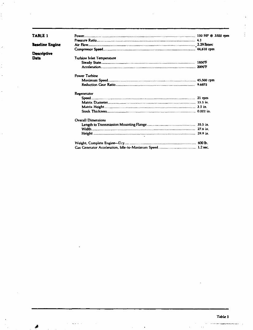
TABLE 1 Power ....................................................................................................................... 150 HP @ 3500 rpm Preesure Ratio ........................................................................................................... 4.1
& r c h En@t Air Flow .................................................................................................................... 2.29 Wsec Compressor Speed ...................................................................................................... 44,610 rpm
Descriptive Data Turbine Inlet Temperature
Steady State .................................................................................................... 185O'F Acceleration ......................................................................................................... 2OOO.F
Power Turbine ................................................................................................. Maximum Spccd 45,500 rpm
Reduction Gear Ratio ...................................................................................... 9.6875
Regenerator ................................................................................................................... Speed 21 rpm
................................................................................................. Matrix Diameter 15.5 in. Matrix Height .................................................................................................... 3.5 in. Stock Thickness ..................... .. ........................................................................... 0.002 in.
Overall Dimensions ......................................... Length to Transmission Mounting Flange 35.5 in.
Width .................................................................................... 27.6 in. Height ....................................................................................... 29.9 in.
Weight, Complete Engine-Cry ............................................................................... 600 lb. Gas Generator Acceleration, Idle-to-Maximum Speed .......................................... 1.2 sec.
Table 1

TABLE 2
Engine Characterization
RPMComp ................................. 22. 877 27. 452 32. 028 36. 603 41. 178 43. 466 44. 610 Press.RatioComp .. P2/Pl ......... 1.545 1.865 2290 2.825 3530 3.865 4.983 Eff . Comp . (1-2. Total) .............. . 765 . 776 . 792 . 797 . 784 . 769 . 766 Eff . C.T. (5-6. Total) ................ . 76 . 78 . 80 . 82 . 84 . 85 .86 Eff . P.T. (6-8. Total) ................... . 67 . 67 . 68 . 685 . 69 . 095 .70 Eff . Burner .................................. . 984 . 986 . 989 . 993 . 997 . 998 . 998 Effectiveness Keg ........................ . 901 . 898 . 892 . 885 . 877 . 874 373 AH Comp.. BTUlLB ................. 22.64 32 87 44.12 56.70 71.79 80.17 84.40 AH C.T.. BTUlLB .................... 24.57 35.05 46.59 59.53 75.02 83.68 83.01 AHP.T..BTUlLB ..................... 8.712 15.42 23.77 32.11 40.02 42.84 48.34 HP.Acc.6Loss.C.T ................. 1.85 2.47 3.33 4.46 5.86 6.70 7.12 HP. Acc . & Loss. P.T .................. 1.80 2.40 3.50 4.90 5.40 5 90 5.90 HP Net Output. P.T ................. 9.5 21.4 42.1 71.3 109.9 128.2 150.9 Fuel Flow. LWHR ...................... 12.5 19.2 29.7 44.1 63.1 73.4 81.5 BSFC. LB/HP-HR ....................... 1.32 . 90 . 71 . 62 . 57 . 57 .54 Gas Flow. LB/SEC W1 ........................................... . 790 1.010 1.293 1.620 2.001 2.181 2.274 w 3 .......................................... . 750 . 957 1.224 1.532 1.889 2.059 2.146 W4 ............................................... . 772 . 986 1.259 1.575 1.942 2.114 2 204 W5 ............................................ . 781 . 997 1.275 1.596 1.970 2.146 2.238 w 6 ............................................. . 769 . 979 1253 1.570 1.941 2 116 2.207 W8 ............................................... . ?87 1.006 1.288 1.613 1.993 2.172 2.266 W9 ............................................... . 791 1.012 1.296 1.626 2.010 2192 2.287 Pressures (Total). PSIA P1 ................................................ 14.67 14.65 14.63 14.58 14.53 14.49 1448 P2 (= P3) ................................... 22.66 27.33 33.49 41.20 50.84 56.02 59.06 P4 ................................................ 22.48 27.12 33.27 40.97 50.60 55.78 58.81 P5 ................................................ 22.08 26.52 32.49 39.98 49.42 54.42 57.42 P6 ................................................ 17.07 18.69 20.88 23 38 25.98 27.01 28 42 P8 ................................................ 15.03 15.15 1532 15.55 15.87 1604 10.16 P9 ................................................ 14.74 14.77 14.82 14.90 15.03 15.10 15.15 Temperatures (Total). "F T1 ................................................. 85 . 85 . 85 85 . 85 . 85 85. T2 .............................................. 178.0 220.3 266.8 318.6 380.6 414.8 432.0 T4 ................................................. 1145.5 1148.4 1150.0 1152.1 1155.1 1158.0 1198.0 T5 .............................................. 1431.4 1494.6 1568.3 16477 17308 1772.3 1850.0 T6 ......................................... 1338.0 1362.9 1394.4 1425.6 1453.5 14637 1527.5 T8 ........................................... 12906 z291.1 1292.2 1293.4 1294.4 1294.6 1339.5 T9 .............................................. 343.3 383.2 429.5 480.6 540.1 571.2 594.9 Flow Leaks LB/LB Into Station 20 ................................................ 00204 . 00214 00215 . 00224 . 00230 . 00235 . 00238
. . . . 25 ........................................... 00689 00636 00585 00539 00507 00498 00496 34 ............................................... 035 .035
. . . . 38 . . . . . . . . . . . . . . . . . . . . . . . . . . . . . . . . . . . . 00235 . 00290 00340 00385 00425 00450 00460
. . . . 39 . . . . . . . . . . . . . . . . . . . . . . . . . . . . . . . . . 00470 . 00580 00660 00770 00850 00900 0092 46 ............................................ 00384 . Q0408 . 00432 . 00460 00493 00517 . 00522
. . . . . 48 . . . . . . . . . . . . . . . . . . . . . . . . . . . . . . . . . . . . 00235 00290 00340 00385 00425 00450 00460 68 . . . . . . . . . . . . . . . . . . . . . . . . . . . . . . . . . . . . . . . . 0196 . 0214 0213 . 0204 0197 0188 0185 80 . . . . . . . . . . . . . . . . . . . . . . . . . . . . . . . . . . . . . . . 00151 . 00156 . 00164 . 00167 00173 . 00178 . 00186 Heat Leaks BTU/LB Flow into Station 20 ........................................ . 354 393 416 423 . 435 . 444 445 40 .......................................... 1 870 1.762 1.553 1.336 1.138 1 055 1.069 50 ...................................... 631 . 980 1742 2 480 3.085 3.311 3 441 60 . . . . . . . . . . . . . . . . . . . . . . . . . . . . . . . . . . . 768 899 1.119 1.663 1.734 1900 1 382 80 ..................... ............. 1.089 1.855 1626 1344 1 185 1096 1.110
Table 2

TABLE 3
Baseline Engine
Final Teardown Earlier Components Component
Hours Condition Huurs Rearon for Removal Endurance-Testing - Tear-Down Results Engine Housing ................................ 4653.7 Good N tt Removed
........................... Engine Insulation 820.7 Good 3828.0 Update (Linerless)
..................... Burner Cap Insulation 1218.4 Good 2256.0 Update (Linerless)
Impeller ............................................ 4654.1 Good Not Removed
First-Stage Turbine Nozzle ............. 4277.0 Good Not Removed
First-Stage Turbine Rotor ............. :. 3970.1 Good Not Removed
Second-Stage Turbine Rotor .......... 575.5 Gccd 3831.8 Disc Cracks
.......................... Total No. of Starts 40861
Table 3
.# . ,
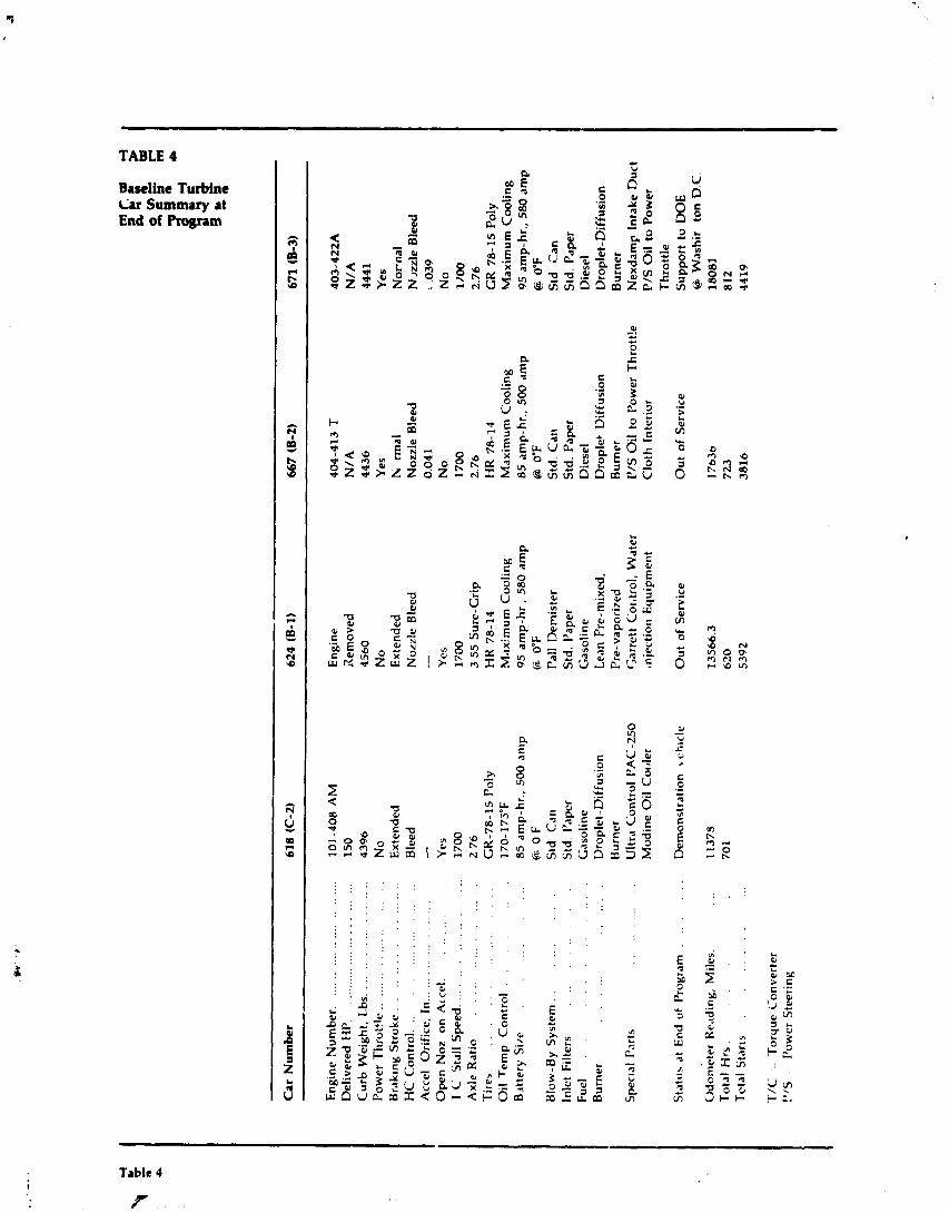
Car
Nu
mb
er
618
((2-
2)
624
(6-1
) 66
7 (8
-2)
671
(B-3
)
Eng
ine
Num
ber.
..
....
....
....
....
....
..
Del
iver
ed H
P.
....
....
....
....
....
....
....
C
urb
Wei
ght,
Lbs
. ..
....
....
....
....
.
Pow
er T
hrot
tle
....
....
....
....
....
. B
rak
~n
g Str
ok
e. .
................
HC
Con
trol
. .
..
..
..
..
..
..
..
..
A
ccel
O
rifi
ce,
In .
....
....
....
....
..
..
..
..
..
.
Op
en N
oz
on
Acc
el..
T
C
Sta
ll S
peed
..................
Axl
e R
atio
..................
Tir
es
..
..
..
..
..
..
..
..
O
il T
emp
C
ontr
ol .
..
..
..
..
Bdt
tery
Sir
e .
..
..
..
Blo
w-B
y S
yste
m .
..
..
..
..
In
let
Fil
ters
.
..
..
..
..
..
Fue
l .
. .
..
..
..
..
..
B
urne
r .
..
..
..
..
..
..
..
Spe
cla1
Par
ts
Sta
tus
at E
nd o
f P
rogr
am
do
met
er R
eadi
ng,
Mil
es.
...
Tot
al H
rs
..
.
..
..
..
.
Tct
al S
tart
s
TIC
= T
orqu
e C
onve
rter
!"
S - P
ower
Ste
erin
g
101-
408
AM
1
50
43
96
No
Ext
ende
d B
leed
-
Yes
17
00
2.76
G
R-7
8-1
5 P
oly
170-
175°
F
85
am
p-h
r.,
500
amp
Q
OF
S
td
Car
l S
td.
Pap
er
Gas
olin
e D
ropl
et-D
iffu
sion
B
urne
r U
ltra
Con
trol
PA
C-2
50
Mo
din
e O
il C
oole
r
Dem
onst
rati
on
s ch
~cl
e
Eng
ine
Xem
oved
45
60
No
E
xten
ded
Noz
zle
Ble
ed
-
Yes
17
00
3 5
5 S
ure-
Gri
p H
R 7
8-14
M
axim
um C
ooli
ng
95
am
p-h
r ,
580
amp
Q
0°
F P
all
Dem
iste
r S
td.
Pap
er
Gas
olin
e L
ean
Pre
-mix
ed,
Pre
-vap
oriz
ed
Gar
rett
Cor
.tro
l, W
ater
m
ject
ion
Equ
ipm
ent
Ou
t of
Ser
vice
404-
413
T
N/
A
4436
Y
es
h;
rmal
N
ozzl
e B
leed
0.
041
No
17
00
2.76
H
R 7
8-14
M
axim
um C
ooli
ng
85 a
mp-
hr.,
500
am
p
@ 0
°F
Std
. Can
S
td.
Pap
er
Die
sel
Dro
plet
Dif
fusi
on
Bur
ner
I'/S
Oil
to
Pow
er T
hrot
t!e
Clo
th I
nter
ior
Ou
t of
Ser
vice
403-
422A
N
/A
4441
Y
es
No
rnal
N ~
ul
e
Bleed
1 ,0
39
No
11
00
2.7
6
GR
78
-15
Pol
y M
axim
um C
ooli
ng
95
am
p-hr
., 5
80 a
mp
@
O'F
Std
C
an
Std
. P
~p
er
Die
sel
Dro
plet
-Dif
fusi
on
Bur
ner
Nex
dam
p In
take
Duc
t P
/S O
il t
o P
ower
T
hro
ttle
S
up
po
rt t
o D
OE
8 W
ash
ir
ton
D.C
. 18081
812
4419

TABLE 5 &sdiac Bastbe TurMat T ~ r b k 1974
contparati~t (1973) (1966) RPdrvtlon Vehide Nobc W ~ t ~ Wehieid Vb L n n l s d B A
Id lcAt Front of Car 71 70 66
Id lcAt Rear of Car 62.5 64 68
30 MPH-Driver's Ear 60 61 59
TABLE 6 Vehicle's Vehide's
Sound Test Left S i Right Side Results DmiIs Decibels
SAE J986a Drive-By T a t Run 1 74 Run 2 72 Average 73
SAE J986a Drive-By Test, Dixrctc Frequencies
Frequency (Hertz) 125 Hz
. SAE J986a Drive-By Test, Discrete Frequencia'
'Procedure modified: Vehicle accelerated wide open threttle from stop instead of wide open thrcttle from 30 rnph.
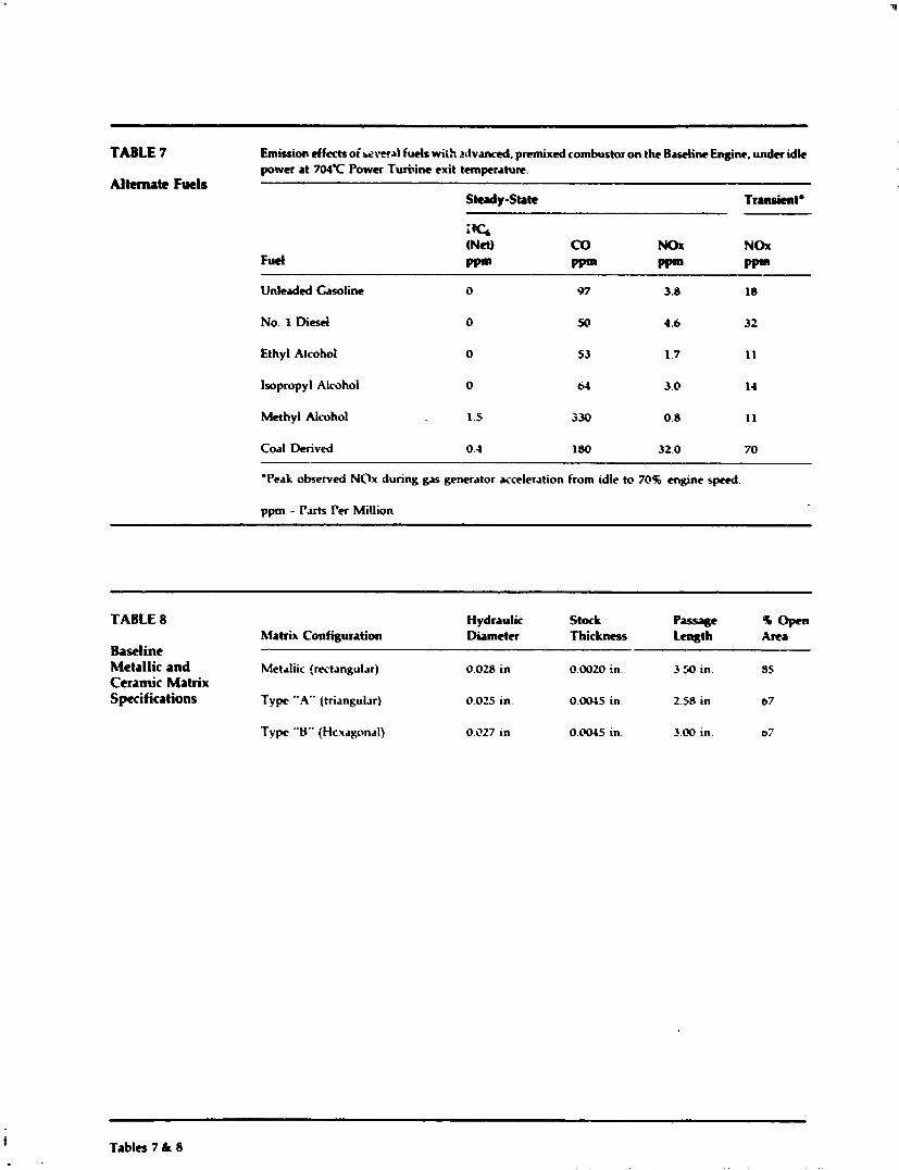
TABLE 7 Emission efferts of &:.ern1 fuels wiih ;rdvancd, premixed combustor on the Baseline Engine, under idle power at 7 O K Power Turhine exit temperature.
Altmute Fwls Steady-State Tmnsieetg
i fG (Net) CO NO1 NOx
Fuel Ppm Ppm Ppm Ppar
Unleadcd Gasoline
No. 1 Diesel
Ethyl Alcohol
isopropyl Alcohol
Methyl Alcohol
Coal Derived
'Peak observed NOx during gas generator acceleration from idle to 70% engine speed
ppm - Parts Per Million
TABLE 8 Hydraulic Stock Passage 96- Matrih Configuration Diameter Thick- W t h Arta
Baseline Metallic and Metrliic (rectangular) ii.028 in 0.0020 in. 3 50 in. 85 Ceramic Matrix Specifications Type ".A" (triangular) 0.025 in. 0.0045 in. 2.58 in 07
Type "0" (Hexagonal) 0.027 in 0.0045 in. 3.00 in. 03
Tables 7 h 8
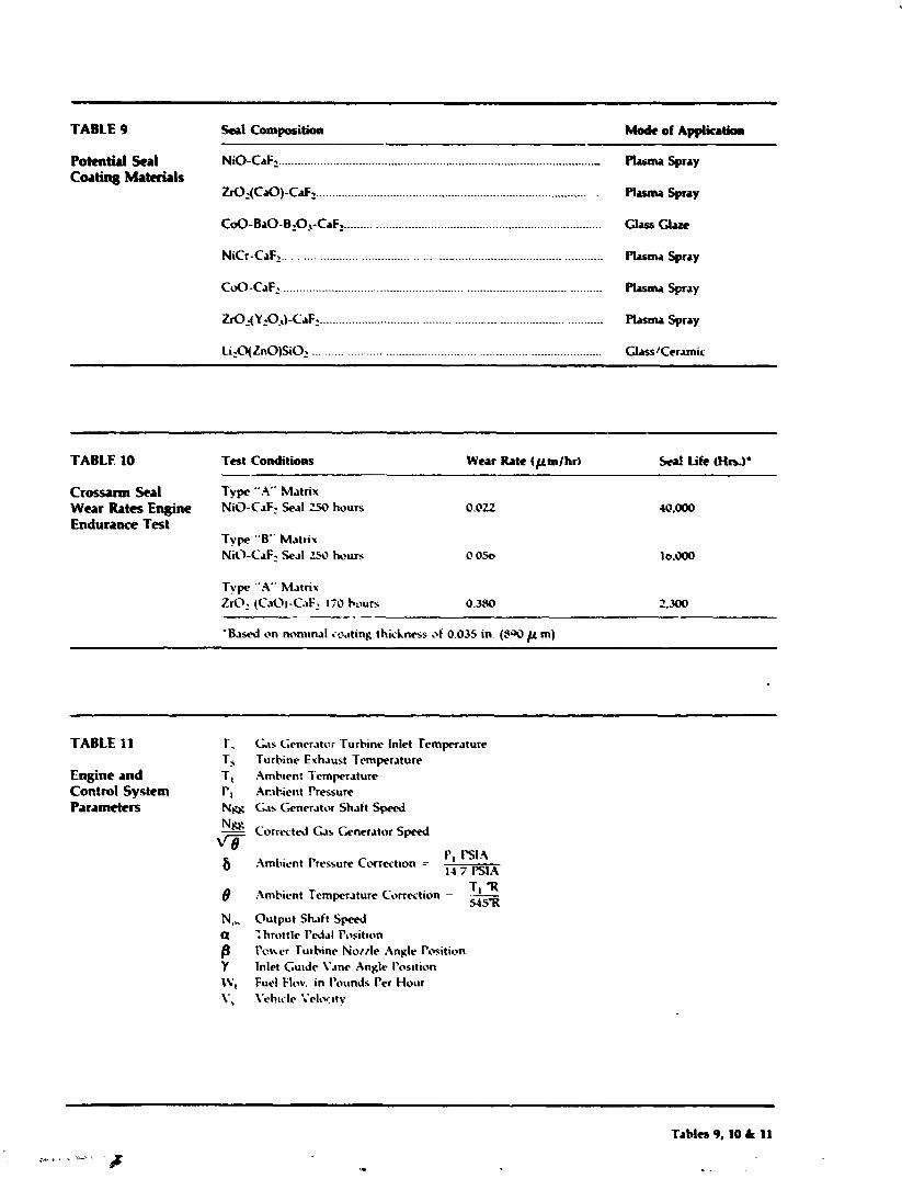
TABLE 9 !kai Composition Mode of Application
............................................................................................... PotCntid &a1 NiO-.CaF2.. .- Phma spray Coat@ Materials
ZrO:(CaO)-CaF2 ..................................................................................... Plrrnu Spray
COO-BaO-B,03-CaF> .............................................................................. Class Glaze
NiCr -CaF2.. .......................................... -. ............................................ Plasma Spray
t02(Y202)-CaF2 .................................................................................... Plasma Spray
TABLE 10 Test Conditions Wear Rate (pmlhr) 5 d Life (Hrr)*
Crossarm Seal Tvpe "A" Matrix Weat fim Engine NiO-CaF: Seal 250 hours Endunnce Test
Tvpe "B" M.~trix NiO-CaF2 Seal 2-50 hours
Type "A" h l ~ t r i x ZrO: (CaOl-CaF: 170 hours 0.350 2.300
---- -
' B a d on nnmtnal coating thickness of 0.035 in. (PW p m)
TABLE I1 T, GIS C;encr.~tu; Turbine Inlet Temperature T, Turbine Exhaust Temperature
Engine and T I ..\mb~m: Tcmprature Control System l', Ambient Pressure Parameters N u GB Generator Shaft Speed
TI 'R t2mbicnt Temperature Correction - - 54577
N,,, Output Shaft S p e d a : hruttlc P d a l Posit~on
f l I ' c ~ c r Turbine Norzle .9nplr Position Y Inlet Gutde Vrne Angle I'osition
W, Furl Flnv. in I'ounds Per Hour V Vchtclc i 'e lw~ty
Tables 9,10 & 11

TABLE 12
F d ECImOmy lmprove.nent of Reciploc~tiag En@mwithCVT versus Stu\dud Automatic Transmission with T ~ M Converter k k - u p
% Economy Improvement Over 3-spd. Trans. T m i u i o n With Toque Conv. Lock-Up -
EPA Cycle A r g WY
20-60 sodo U h Highway Coarpodte MPH MPH
--
4-Speed Auto. Trans. With Toque Conv. Lock-Up 4.5 5.5 4.9 ' 9.2 7.0
MTI Hydromechanicd (Chryder A-904 Oil Pump) 7.7 1.4 5.2 6.5 0.3
MTl Hydromechanicd (Mfl Oil Pump) 9.2 2.5 6.1 7.5 1.1
TABLE 13
Fm Versus Geared Rotar Fuel Flow at 50 P a n t Speed Road Load Points for Baseline Vehicle
Full Accessories Minimum Amssorics (Includiqx AIQ
Power Fuel Power F d Turbine now, Turbine Row,
RPM MPH Horsepower LbIHr Horsepower LblHr
600 10 Geared Rotor 2.4 10.4 5.2 11.1 Free Rotor 3.4" 10.4 6.2" 11.4
900 20 Gear& Rotor 5.2 11.0 Free Rotor 6.2. 10.9 .
'Requires higher gas generator speed.
"Includes 1 HP compensation for externally-driven engine auxiliary drive (regenerator, lube pump, fuel control, air pump).
Tables 12 & 13
I --
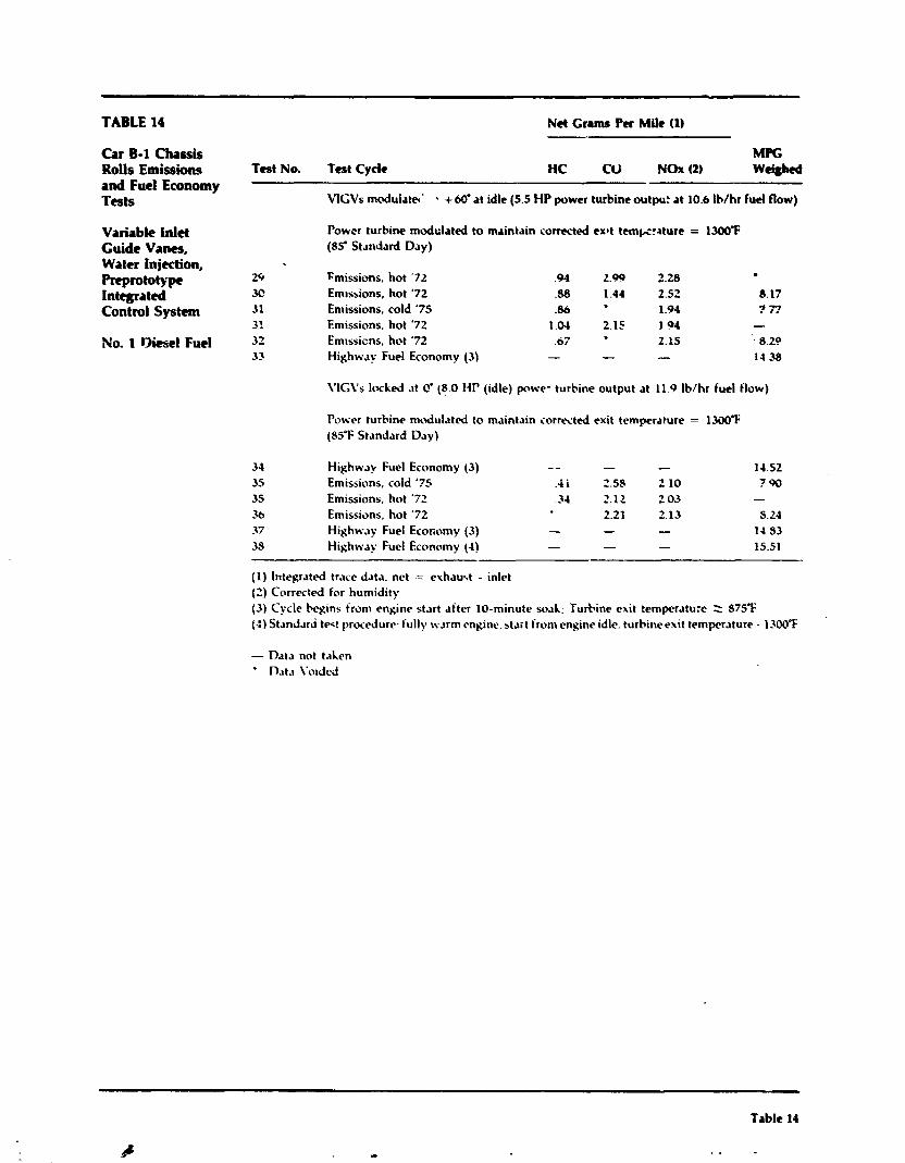
TABLE 14 Net Grams Per Mile (1)
Car B-1 Chassis Rolls Emissions and Fuel Economy Tests
Variable Inlet Guide Vanes, Water Injection, ~ ~ ~ t o t , p c Integrated Contml System
No. 1 Oitscl Fuel
MPC Test No. Test Cycle HC CU NOx (2) w-
VlCVs mdulatet ' . +60' at idle (5.5 HP power turbine output a t 10.6 Ib/hr fuel flow)
Powcr turbine modulated to maintain corn-ted extt tempzature = 13WF (85' Standard Day)
29 Fmissions, hot '72 .94 2.99 2.28 ,U? Em~ssions, hot '72 .SB 1.44 2.52 8.17 31 En~issions, cold '75 .86 1.94 ? 7? 31 Emissions, hot '72 1.04 2.15 1 0 4 - 32 Em~ssicns, hot '72 .07 2.15 . 8.20 32 Highway Fuel Economy (3) - - - 11 -38
\'ICVs locked .it c' (8.0 HI' (idle) p w e - turbine output at 11.0 Ib/hr fuel flow)
Power turbine modul.lted to maintain corrected exit temperature = 13WT (8SeF Standard Day)
3.1 Highw~y Fuel Economy (3) - - - - 14.52 35 Emissions, cold '71 . t i 2.56 2 10 790 35 Emissions, hot '7' .31 2.12 2 03 - 36 Emissions, hot '72 2 2 2.13 S.24 37 Highway Fuel Economy (3) - - - 11 83 38 Highw~y Fuel Economy (1) - - - 15.51
(1) Ilrtegrated trace data, net = exhau*.t - inlet (2) Corrected ior humidity (3) Cycle begins from engine start after 10-minute soah: Turbine exit temperature : S75.F (4) Standari test yrcxedure. h ~ l l y warm r n g i ~ ~ e , start from engine idle. turbineexit temperature - 13&YF
- Data not t.~hen n ~ t . ~ voided
Table I4
b - . .
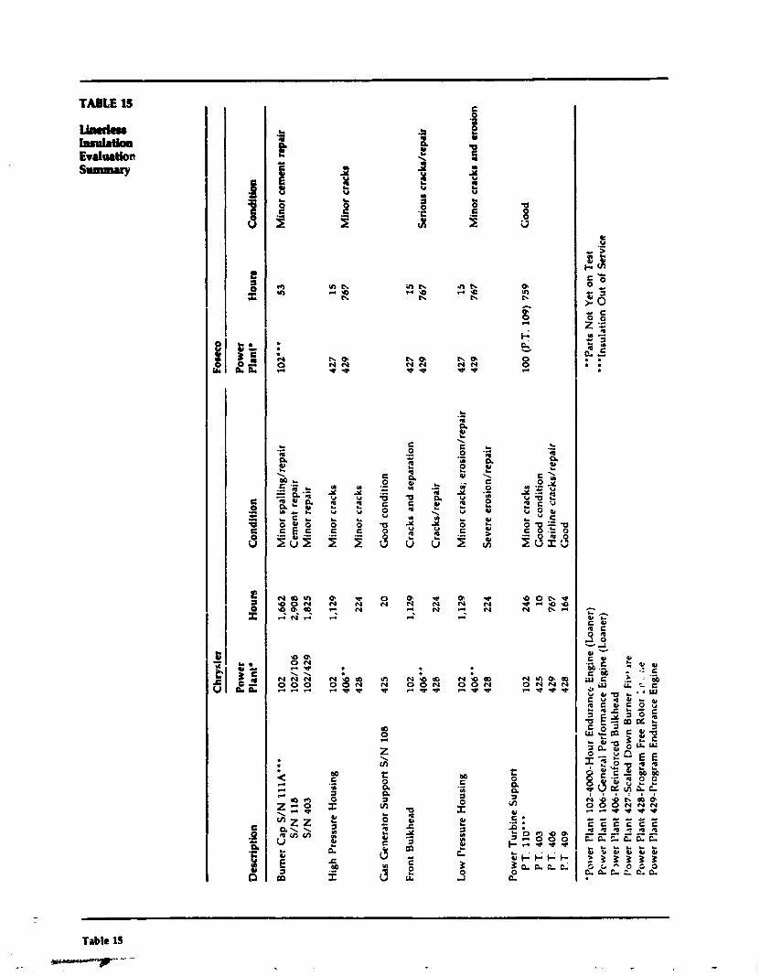
-
Des
crip
tion
P
ower
P
lant
D
Ho
urs
C
ondi
tion
P
ower
P
lant
* H
ou
rs
Con
ditio
n
Bur
ner
Cap
S/N
'L
llA"'
10
2 1,
662
Min
or s
pall
ingl
repa
ir
10
2**
* 53
M
inor
cem
ent
repa
ir S
/N 1
18
102/
106
2,90
8 C
emen
t re
pair
S
/N 4
03
102/
429
1,82
5 M
inor
rep
air
Hig
h P
ress
ure
Hou
sing
10
2 1,
129
Min
or c
rack
s 40
6"
4 28
22
4 M
inor
cra
cks
Cas
Gen
erat
or S
uppo
rt S
/N 1
08
425
20
Goo
d co
ndit
ion
Fron
t B
ulkh
ead
Low
Pre
ssur
e H
ousi
ng
427
15
42
9 76
7 M
inor
cra
cks
102
1,12
9 C
rack
s an
d se
para
tion
42
7 1
5
406"
42
9 76
7 S
rio
ur
crac
b/re
pair
42
8 22
4 C
rack
s/re
pair
102
1,12
9 M
inor
cra
cks;
ero
sion
/rep
air
427
15
40
6"
429
767
Min
or c
rack
s an
d er
osio
n 4 2
8 22
4 S
ever
e er
osio
n/re
pair
Pow
er T
urbi
ne S
uppo
rt
PT
. 11
0"'
102
246
Min
or c
rack
s 10
0 (P
.T. 1
09)
759
Good
P T
. 40
3 42
5 10
G
ood
cond
itio
n P
T. 4
06
429
767
Hai
rlin
e cr
acks
/rep
air
P.T
40
9 4
28
164
<h
od
-
"Por
rer
l'lan
t 10
2-40
00-H
our
End
uran
ce E
ngin
e (L
oane
r)
**P
arts
Not
Yet
on
Tes
t PC w
rr P
lant
106
-Gen
eral
Per
fo~
man
ce Eng
ine
(Loa
ner)
"'
Insu
latio
n O
ut
of S
ervi
ce
P~
we
r l'lan
t 40
6-R
einf
orce
d B
ulkh
ead
Pow
er P
lant
427
-Sca
led
Dow
n B
urne
r F
irel
re
Pow
er P
lant
428
-Pro
gram
Fre
e R
otor
I-
.. :.c
Po
wer
Pla
nt 4
29-P
rogr
am E
ndur
ance
Eng
ine
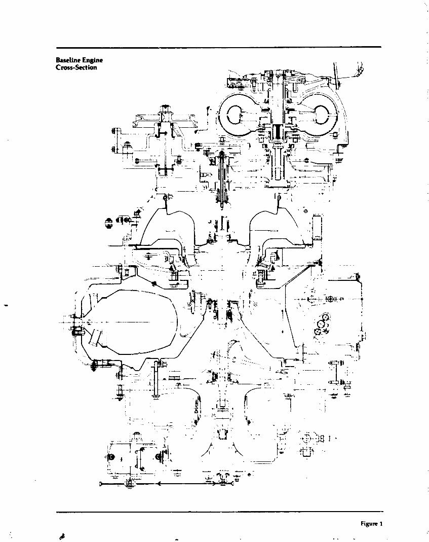
Figure 1
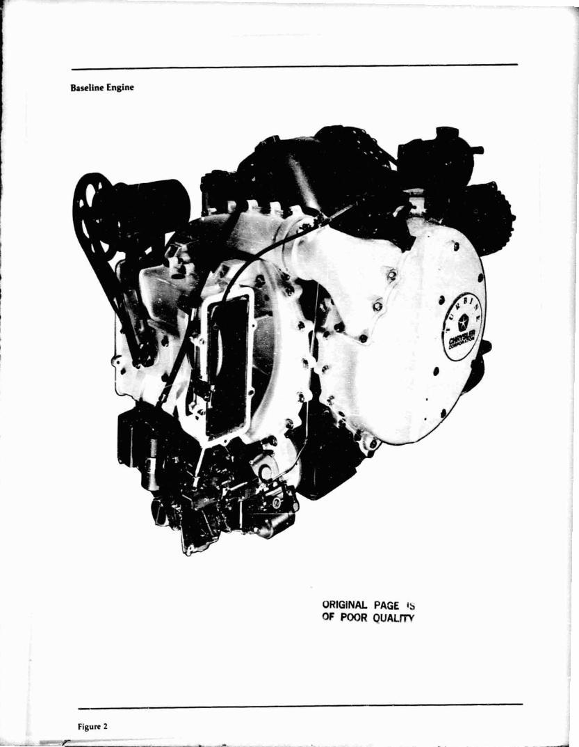
Baseline Engine
ORIGINAL PAGE IS OF POOR OUALIV
1 Figure 2
_ -?9--- - . L 3

Engine Characterization Schematic
Intake T
Heat Leakc
Figure 3
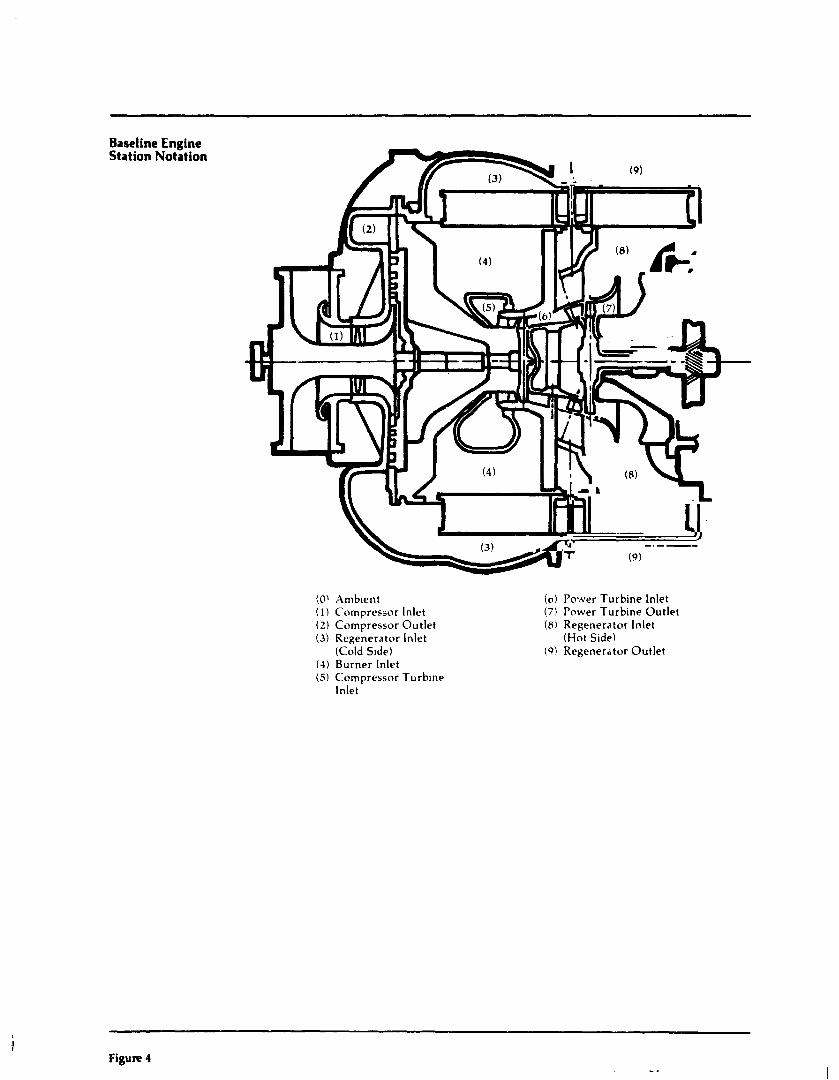
Baseline Engine Station Notation
(O\ A m b ~ e n t ( 1 ) Compressor Inlet (2) Compressor Out!et (3) Regenerator Inlet
(Cold S ~ d e ) (4) Burner Inlet (5) Compressor Turbine
Inlet
(01 Power Turbine Inlet ( 7 ) Power Turbine Out le t (8) Regenera:or Inlet
(Hot Side) (9 ) Regenerator Out le t
Figure 4
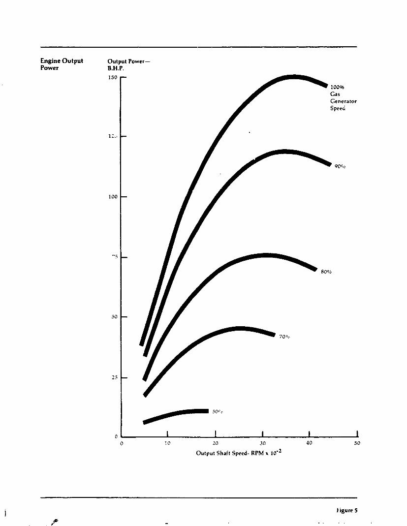
Engine Output Power
Output Power- B.H.P.
Gas Gener Speed
10 20 30 40
Output Shaft Speed- RPM x lo-'
Figure 5
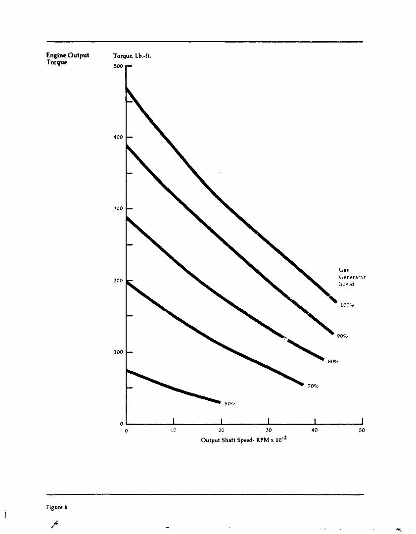
Engine Output Torque
Torque, Lb.-ft.
Gas Generatw 5r)~c'd
100*~0
Output Shaft Speed- RPM x lom2
Figure 6
d P
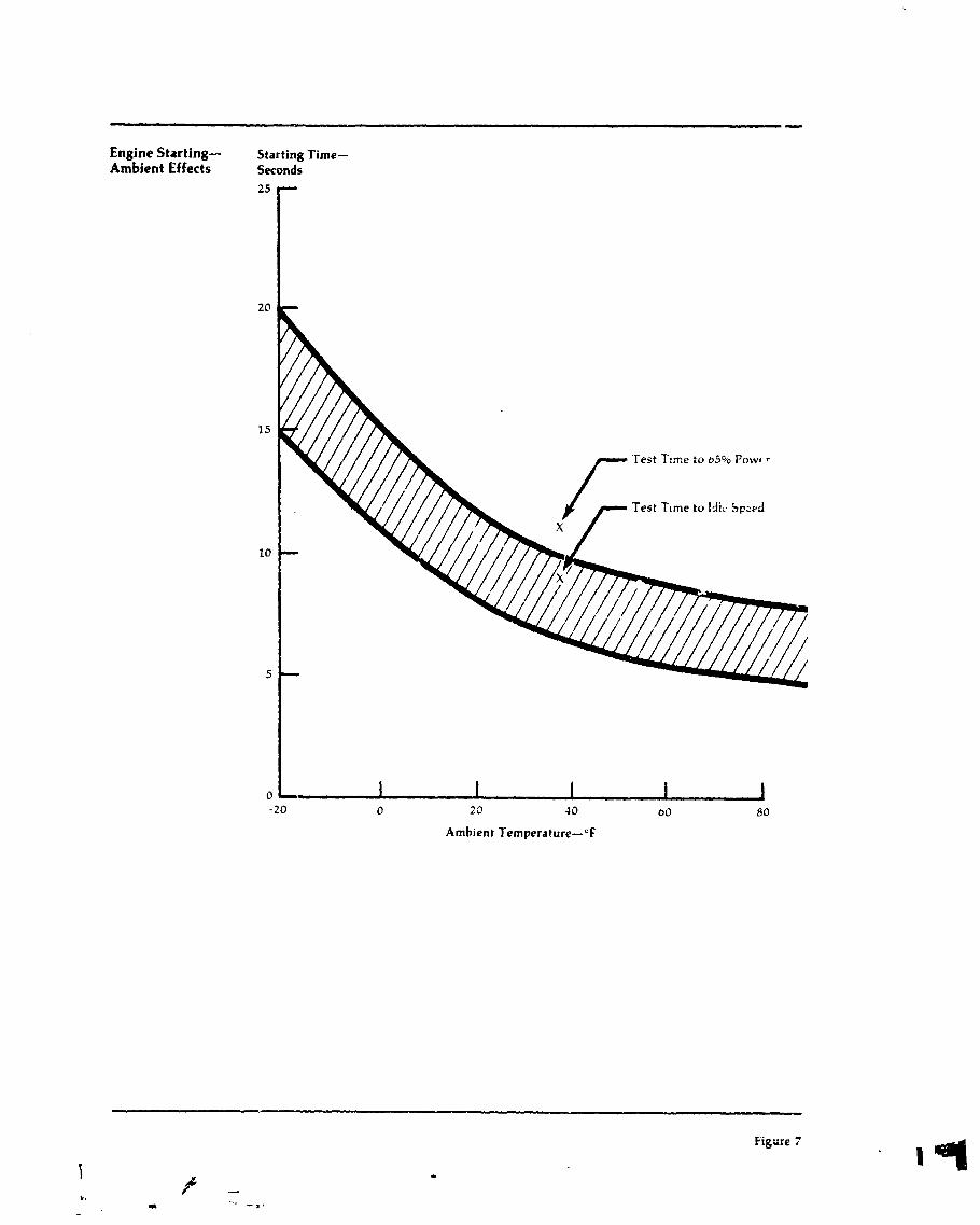
Engine Starting- Starting Time- Ambient Effects Seconds
Ambient Temperature-OF
Figure 7
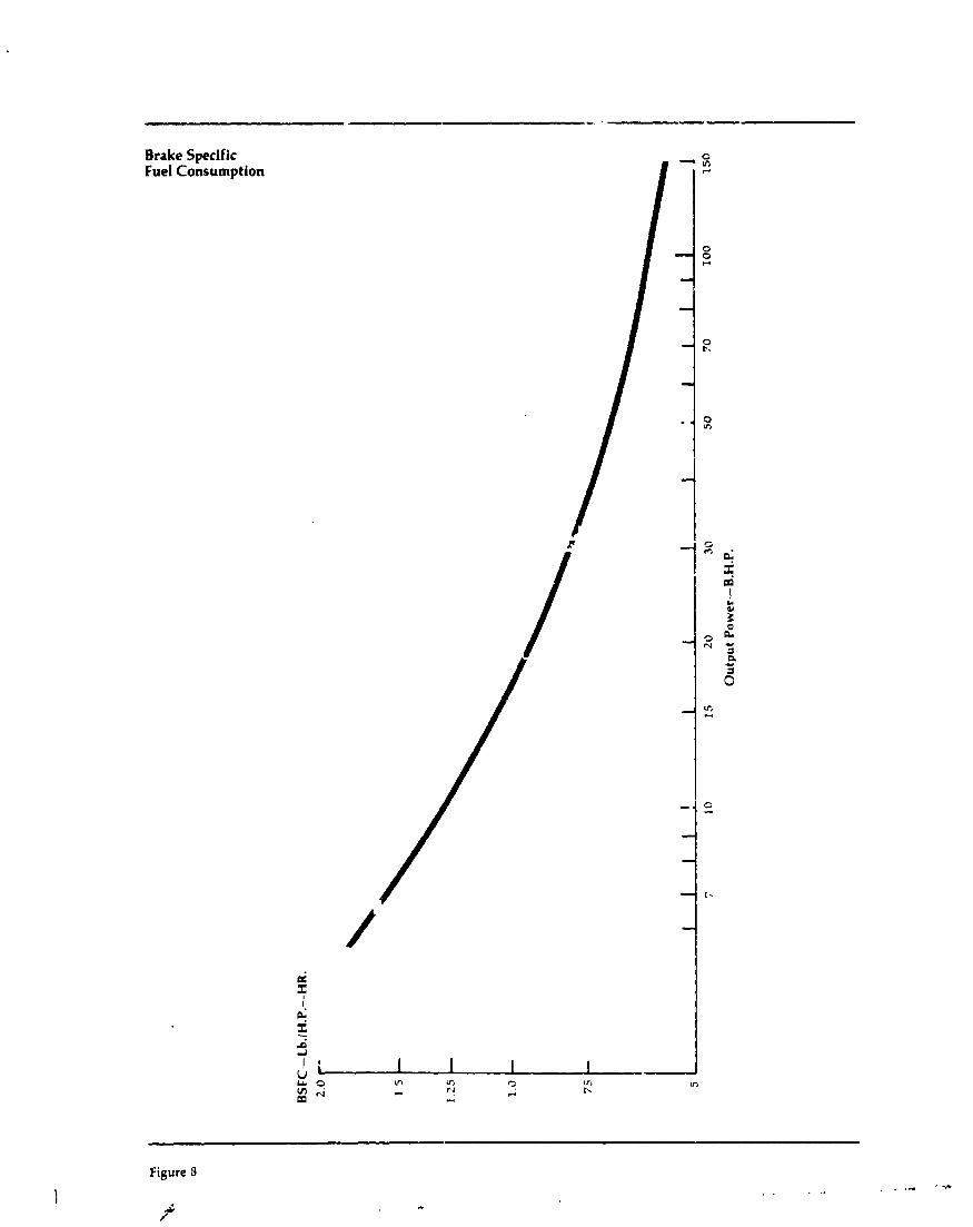
Brake Specific Fuel Consumption
i
P
- - t.
-
$ I
.+ r_ d II l i
U I In v,
I L % 2 - C? ?
v, t-.
L n
m H e
Figure 3
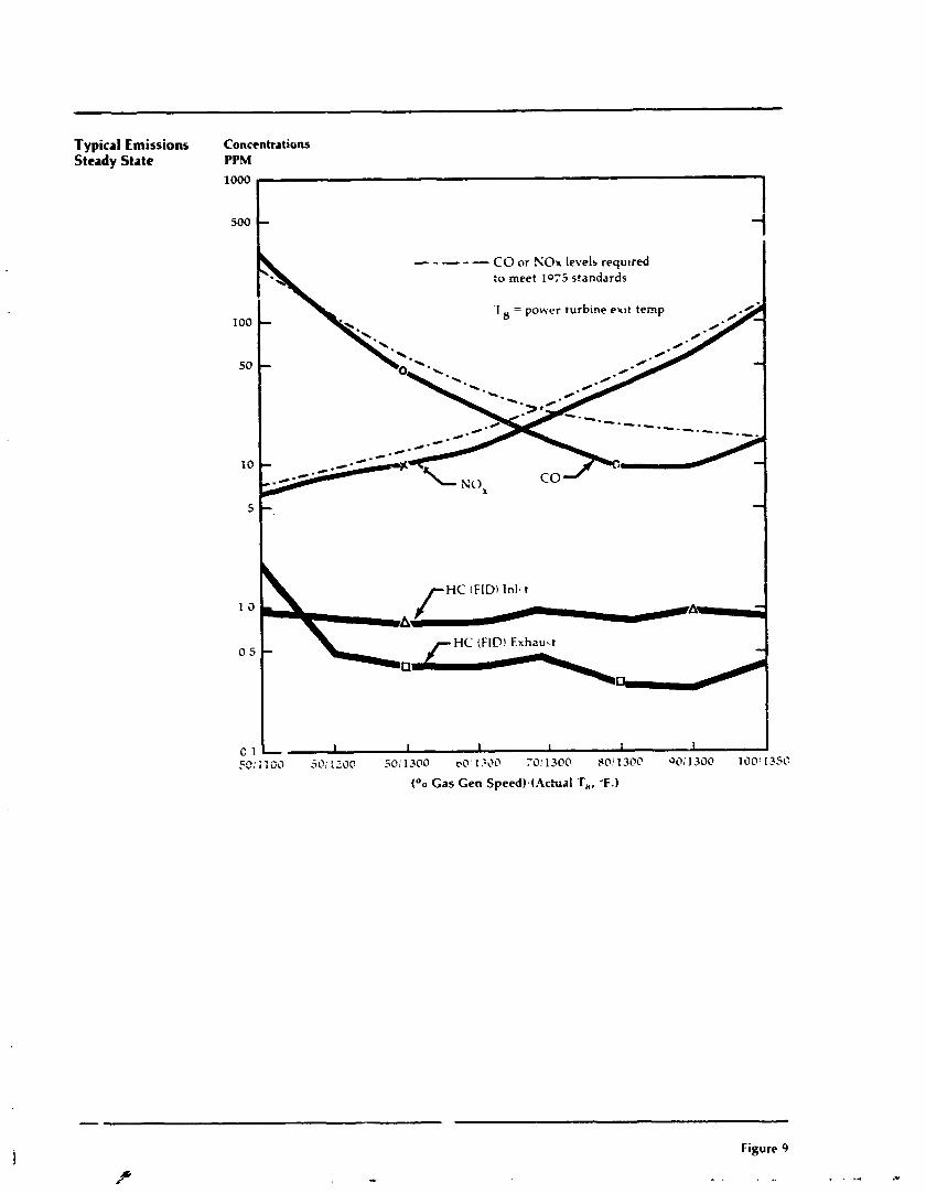
Typical Emissions Concentratians Steady State PPM
--A-e CO or NO* levels required :u meet 1075 standards
C 1 L I 1 I 1 1 1 I 53: 1100 50; :ZOO i0i 1300 oO'l.ZOO 70: 1300 PO! 130c 917; 1300 100: 13SC
too Gas Gen Speed).(ActuaI T,, -F.)
Figure 9
s . . ..
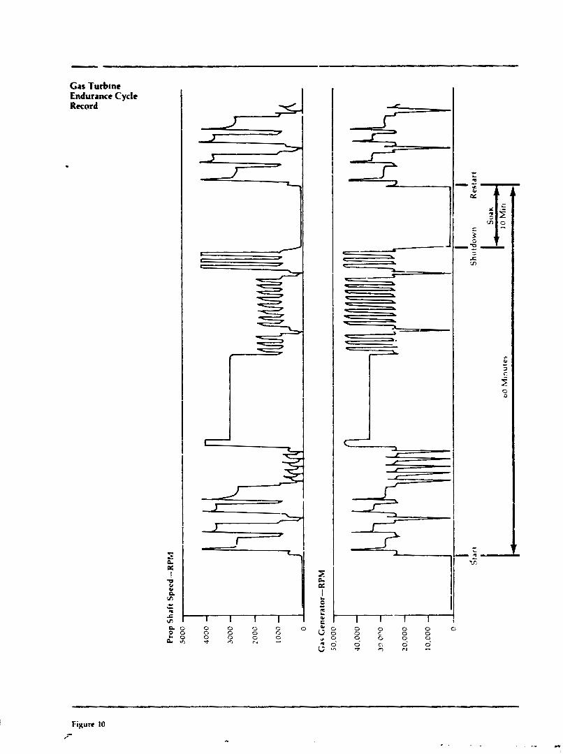
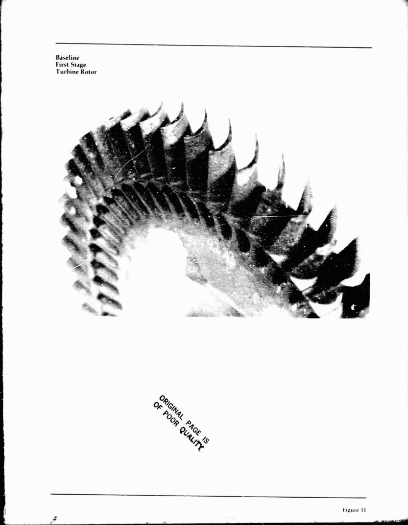
Baseline First Stage Turhinr Rotor
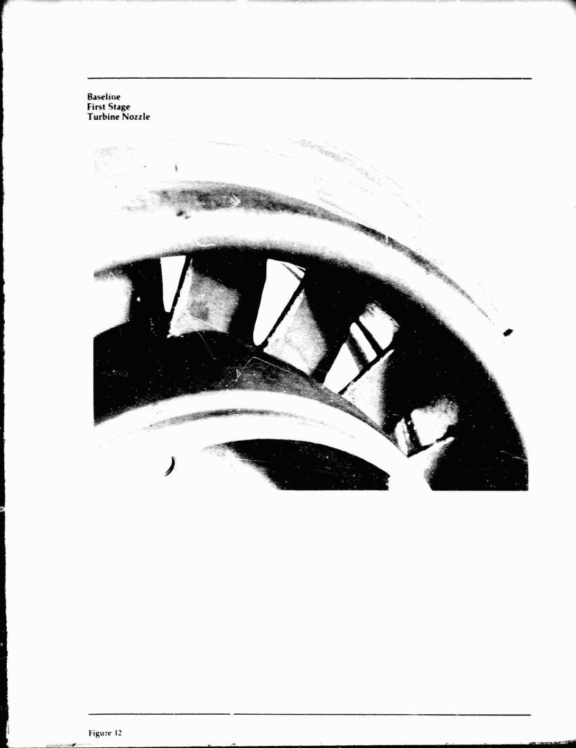
Baseline First Stage Turbine Nozzle
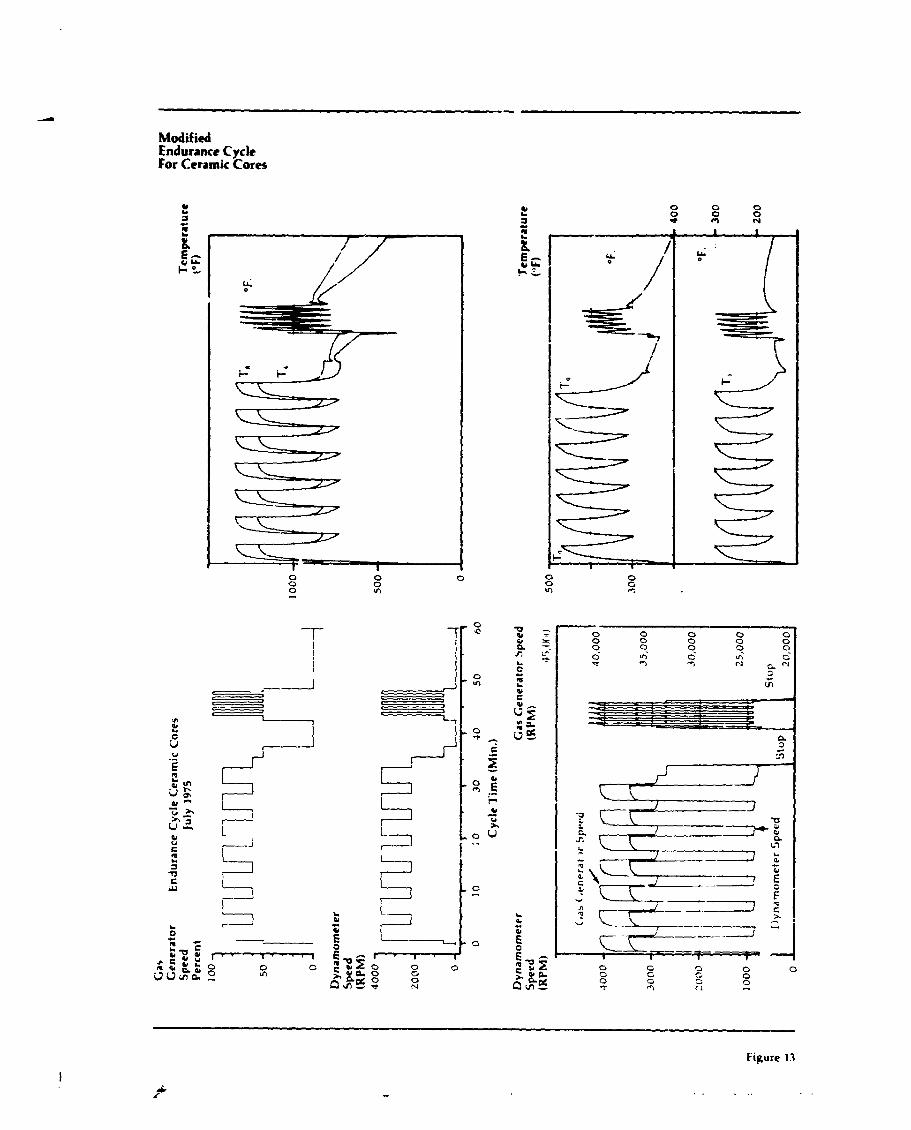
Modified Endurance Cycle For Ceramic Cores
Figure 13
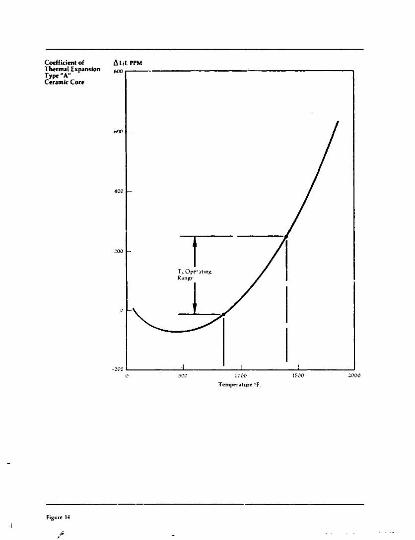
Coefficient of Thermal Expansion Type " A Ceramic Core
A LIL PPM
500 1000 1500
Temperature OF.
Figure 14
.G I
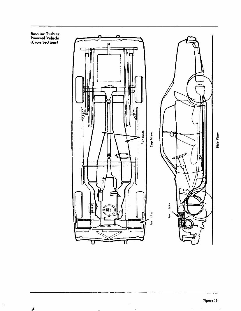
Baseline Turbine Powered Vehicle iCmss Sections)
Figure IS
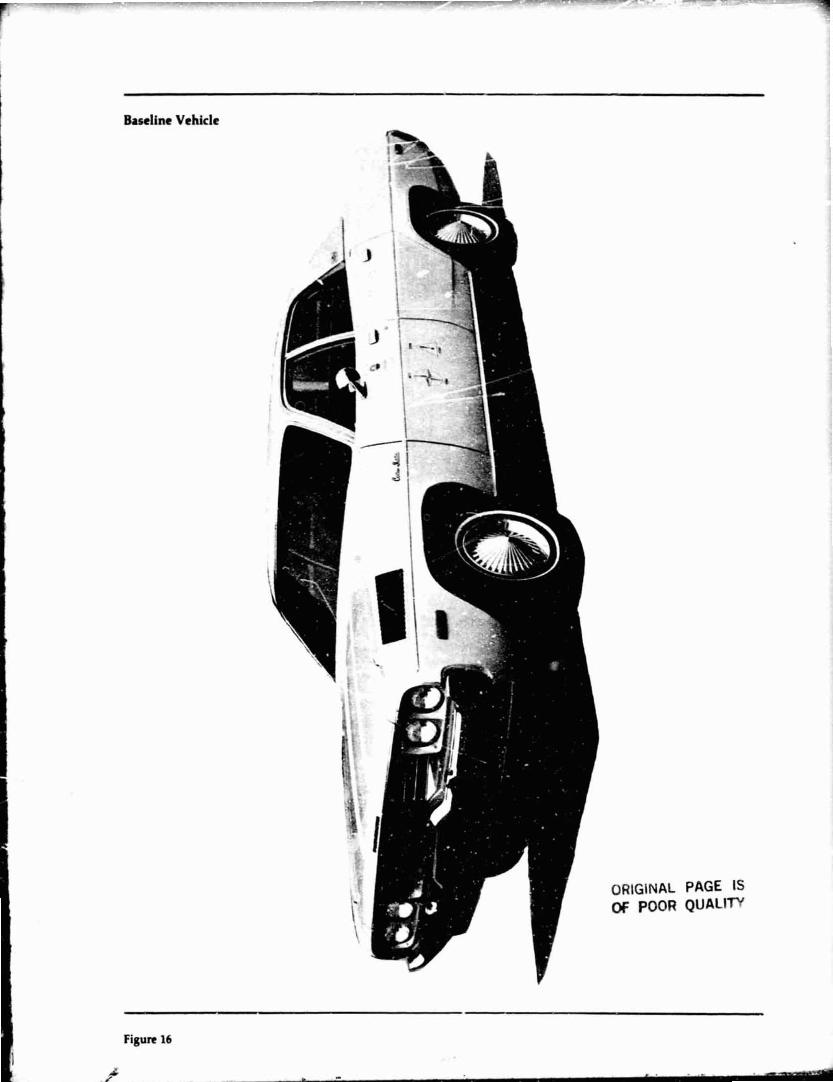
Baseline Vehicle
GlNAL POOR
PAGE QUA1
Figure 16
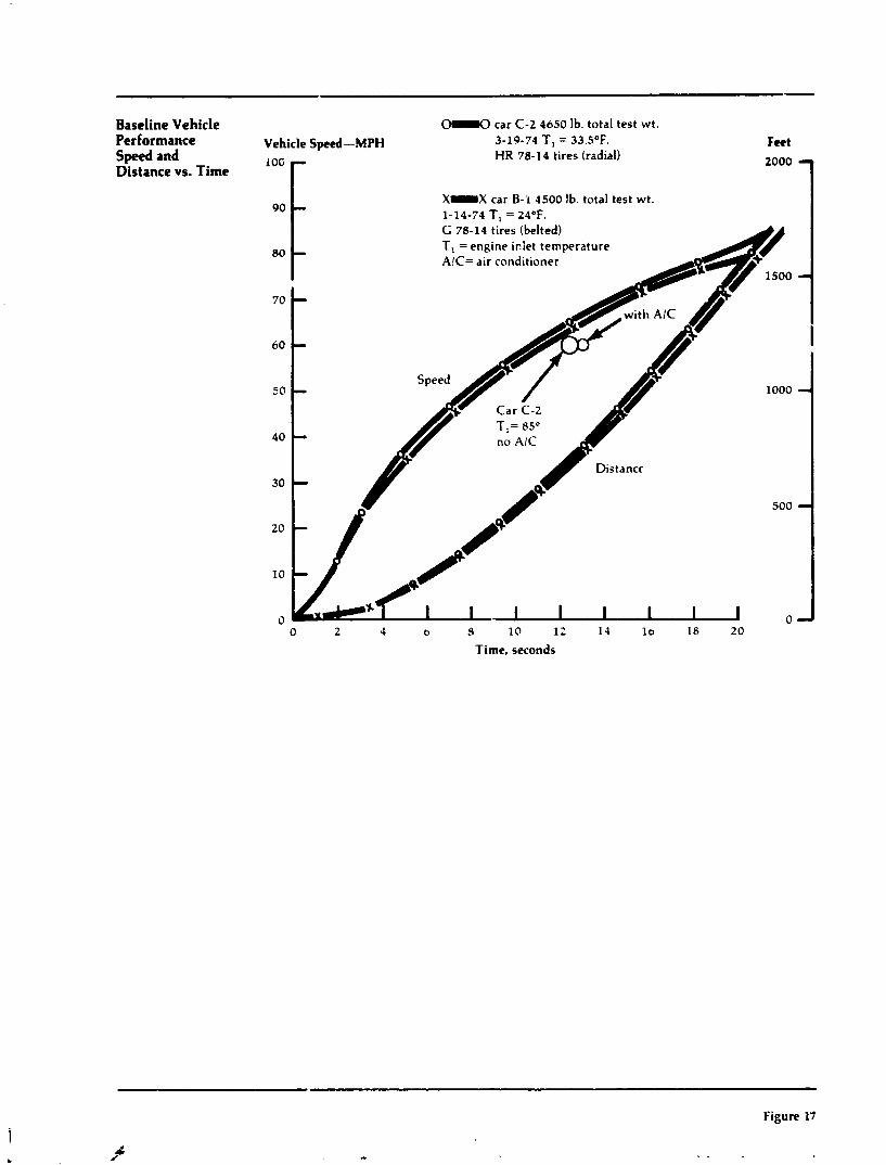
Baseline Vehicle Performance Speed and Distance vs. Time
OI.0 car C-2 4650 Ib. total test wt.
Vehicle Speed-MPH 3-19-74 T, = 33.S°F. HR 78-14 tires (radial)
iOG r X X car B-i 4500 lb. total test wt. 1-14-74 T, = 24'F.
Feet
t G 78-14 t i e s (belted) T, = engine iciet temperature A!C= air conditioner
- I
- Speed
- no AIC
Distancr
500
- 0 2 1 b 9 10 12 11 l o 18 20
Time, seconds
Figure 17
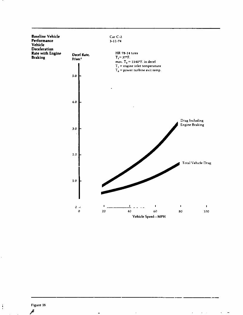
Baseline Vehicle Performance Vehicle Deceleration Rate with Engine Braking
Duel Rate, ftlseca
Car C-2 3-11-74
HR 78-14 ttres TI= 37OF. max. T, = 1140°F. in decel T I = engine inlet temperature T, = power turbine exit temp.
Drag Including Engine Braking
Total Veh~cle Drag
I I ----- .- - . , - I I
20 4 0 60 80
Vehicle Speed-MPH
Figure 18
k Y

Baseline Vehicle Fuel Consumption Effect of Cycle Temperature
Fuel Consumption, MPG
0 - 0 T,= Match a t Ambient i1132°-11480F ) (power t u r b ~ n e e x ~ t temp.)
0-II] Comparable 5.1. Englne
0 2 0 4 0 b0 80 100
Vehicle Speed, MPH
Figure 19
- .

Effect of Exhaust Pressure On Engine Performance
Engine C.:tput- Horsepower
Design Engine Speed
0 4 8 12 16 20 2 4
Exhaust Pressure-in H,O (gauge)
Figure 20
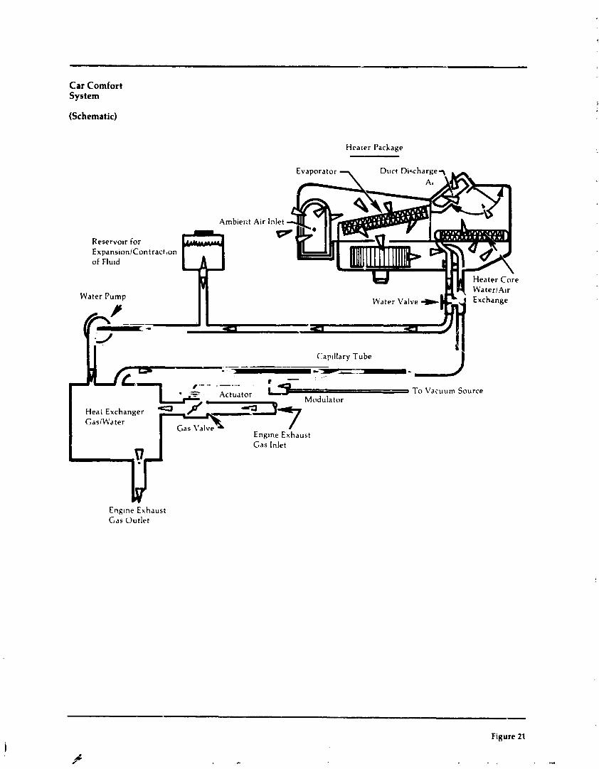
Car Comfort System
(Schematic)
Heater Package
Rese rvo~r for Expans~onlContract ,on of F lu~d
Water Pump Water Valve
.---- ----- f '- '- -
Gas Inlet
Englne Exhaust Gas Out le t
- Figure 21
Engine Speed Timers in Vehicle Trunk
-. Figure 22
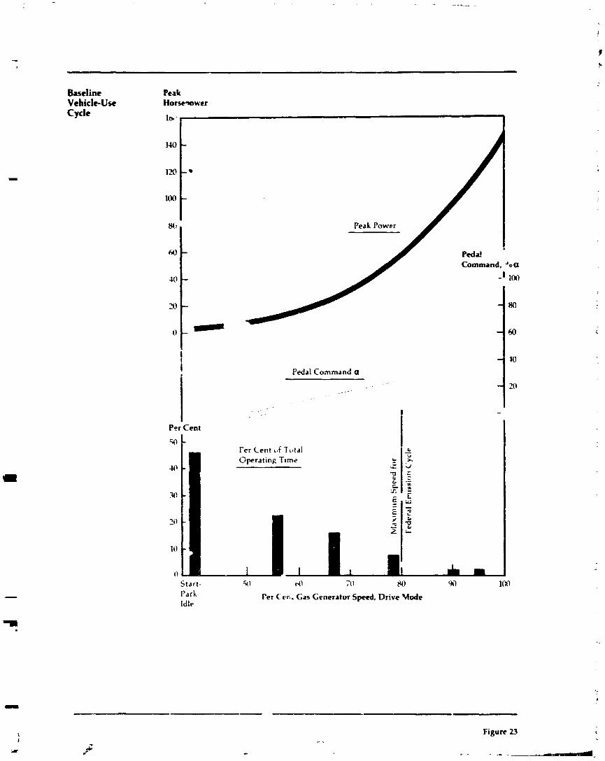
Baseline Vehicle-Use Cycle
Per Cent
Peak Power
Command, Joa
Pedal Command a
Fer Cent uf Tctal G p e r a t i n ~ Ttme
Start- 31 (.(I 711 80 Park Per Ccr. . Gas Generator Speed, Drive Uode Idle
Figure 23 *
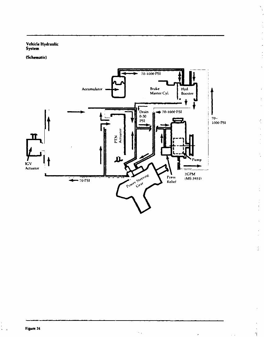
Vehicle Hydraulic System
(Schematic)
70-1000 I'S1
Accumulator Brahe
& Hyd.
Master Cyl. Bwster
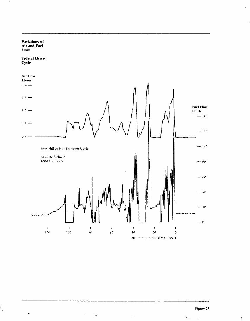
Variations of Air md Fuel Flow
Federal Drive Cycle
.air Flow Lbssec.
0 9 - F1r5t H.racl~~rc Hill \'chr,.lt. ot Hot ;\\I En~~r;l;iat) L'v~lt.
4000 1 \r 1nc.rt1.1
2:4!1(4~\\1\11 1 :0 1 100 I 3 I (1 - 10 1 20 1 I'imr-sf<. L+ 1' I I - - 0 217
Furl Flow Lb tir. - 140
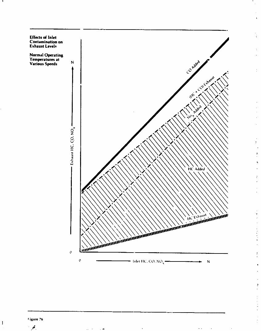
Effects of Inlet Contamination on Euhust Leveb
Normal Operating Temptraturn at Various Spuds
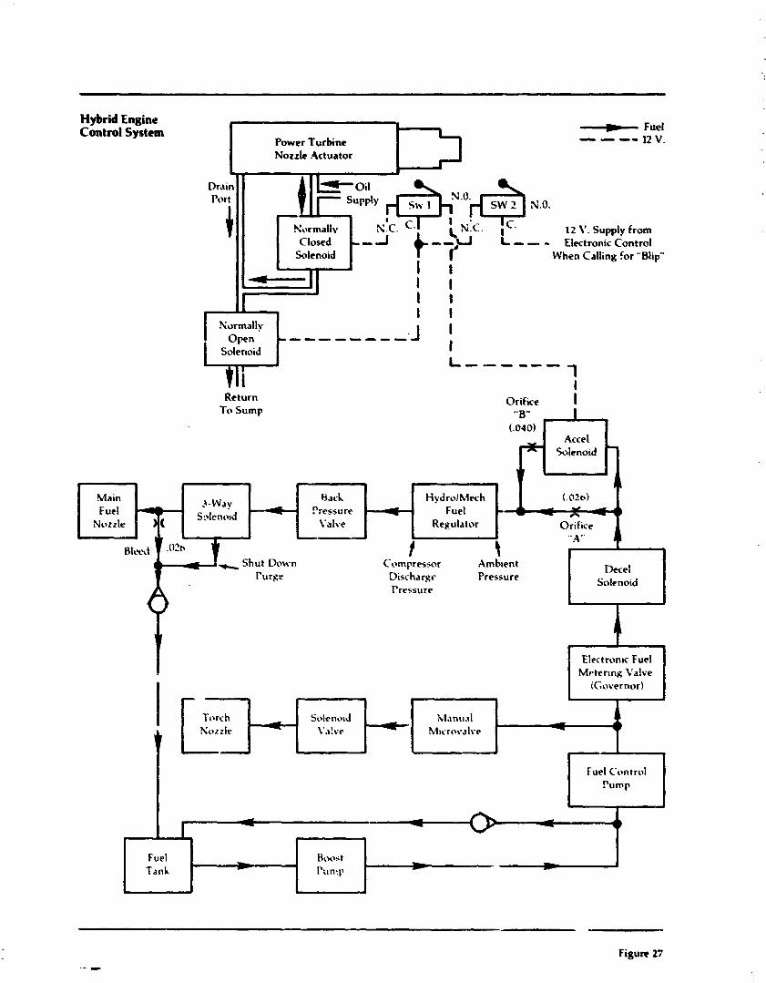
Hybrid Engine Control System - Fuel
Power Turbine - -- -- 12 V. Nozzle Actuator -
Drain = o i l Port
f I
d ( ? > r j i X.O.
Normallv N.C. 12 V. Supply from Closed --A - > - - ElectronicContml
Solenoid I' When Calling for "Blip" J . I t
I I I I I
I I Normally
O v n --------- Solenoid
J ' I I-,-,,,,
1 I
Return Orifice To Sump
I " B'. I -
(.040)
* A r-
Main 8ach HydrolMech Pressure Fuel
Valve Regulator >
t t Cornpresl;nr Amb~ent
Discharge Pressure Decel
Solenoid Pressure
i
Electron~c Fuel Mrterlng Valve
iGovernor)
Solenold Manual - T
Fuel Control Pump
l. - Fuel * Hoo?;t Tank rr~n!p D- * L
J
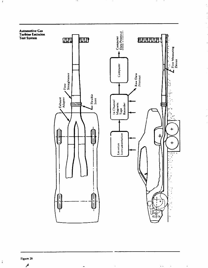
Automotive Gas Turbine Emission Test System
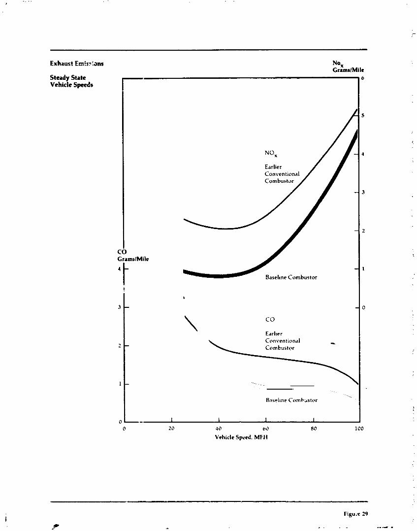
Exhaust Emis?:ans NO, CramslMile
Steady State
I- -, 6
Vehicle Speeds
CO
Conventional
- 2
GramslMiie
t - 1
0
Baselme Combustor
0 20 4 0 bL1 SO 1 co Vehicle Speed. MFH
!
3
7 -
1
0
L
- -
\ CO
Earlier Conventinnal - Combustor
- 1. Raspi~ne C o m b s t o r
-. - 1 I I I
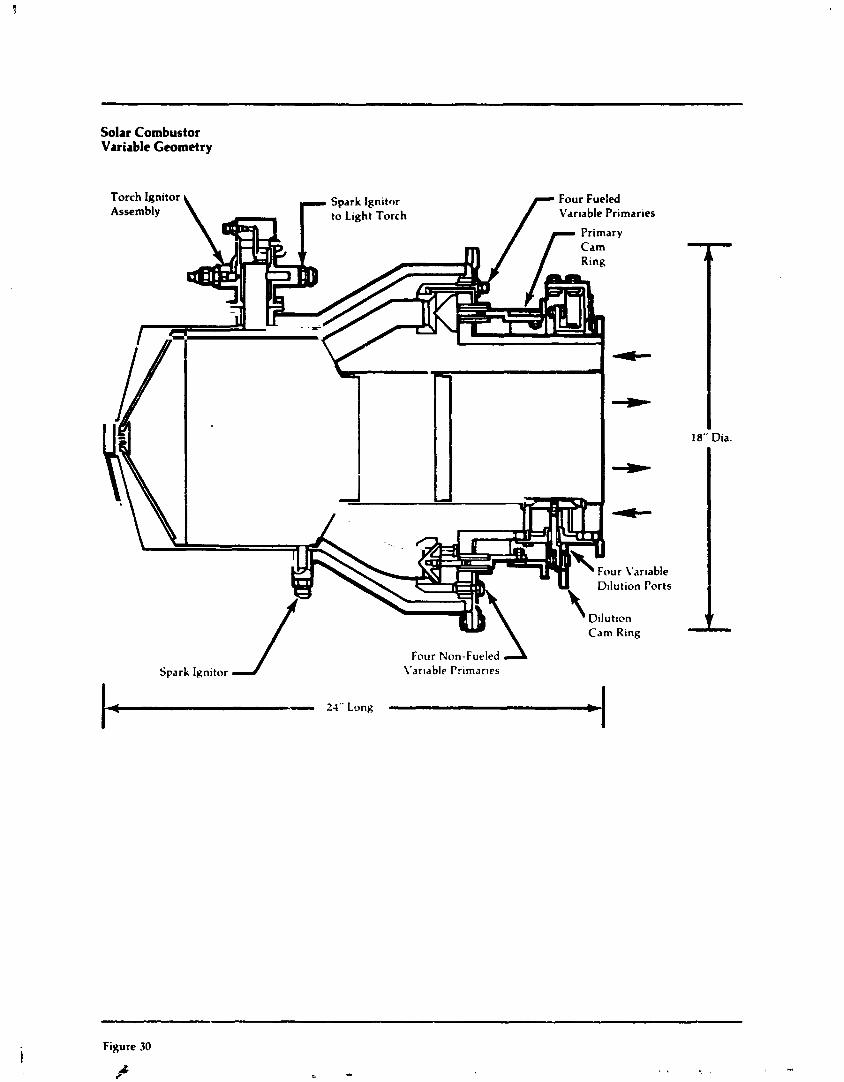
Solar Combustor Variable Geometry
1 18" Dia.
Spark Ignitor J Four Non-Fueled 2 L'arlable Primar~es
Figure 30
X a
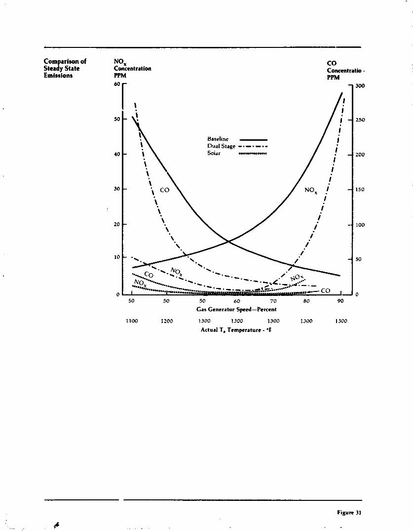
Comparison of Steady State Emissions
Baseline - Dual Stage ------- Solar n m u . u m m a
50 50 50 60 70 80 90
Gas Generator Speed-Percent
1100 1 200 1300 1300 1300 1300 1300
Actual T, Temperature - OF
Figure 31
4 . - - . , ,
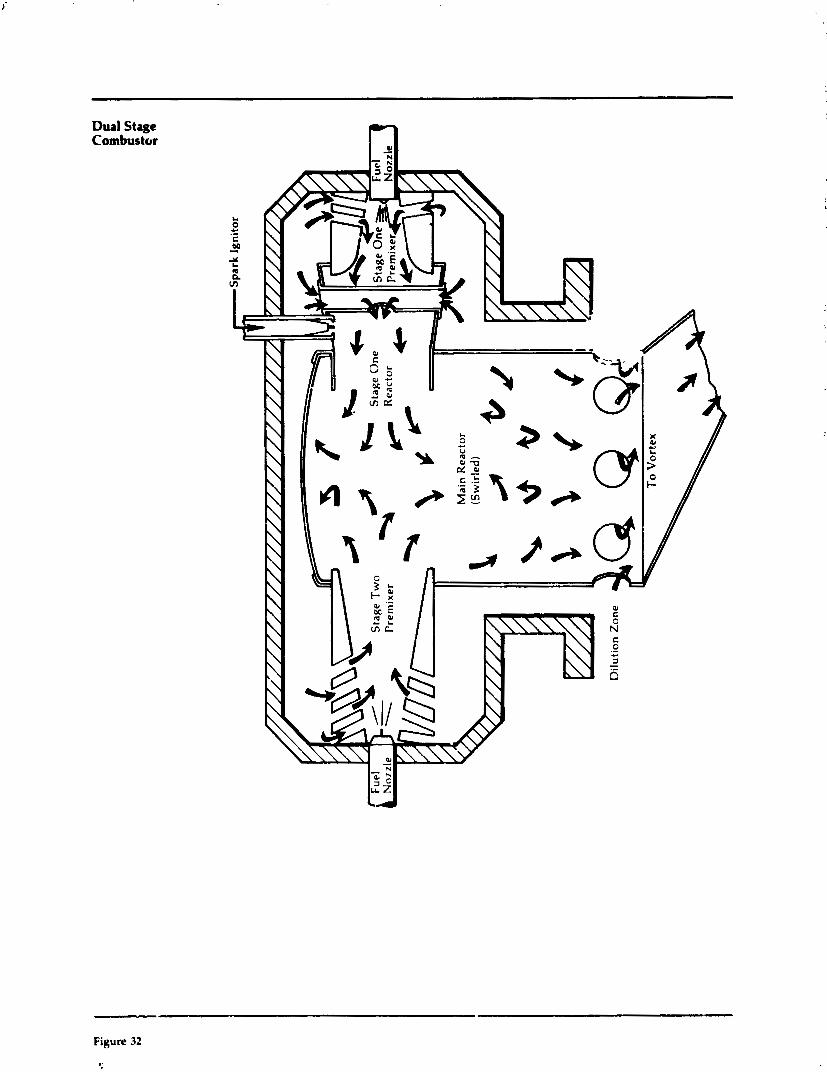
Dual Stage Combustor
Figure 32
5
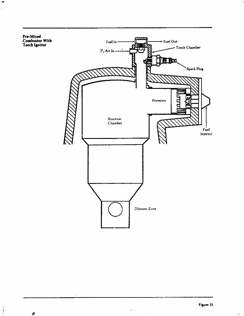
Pre-Mixed Combustor With Torch Ignitor
React ion Chamber
Figure 33

0 I I - I
50 00 70 80 QO 100
Gas Generator Speed-Percent
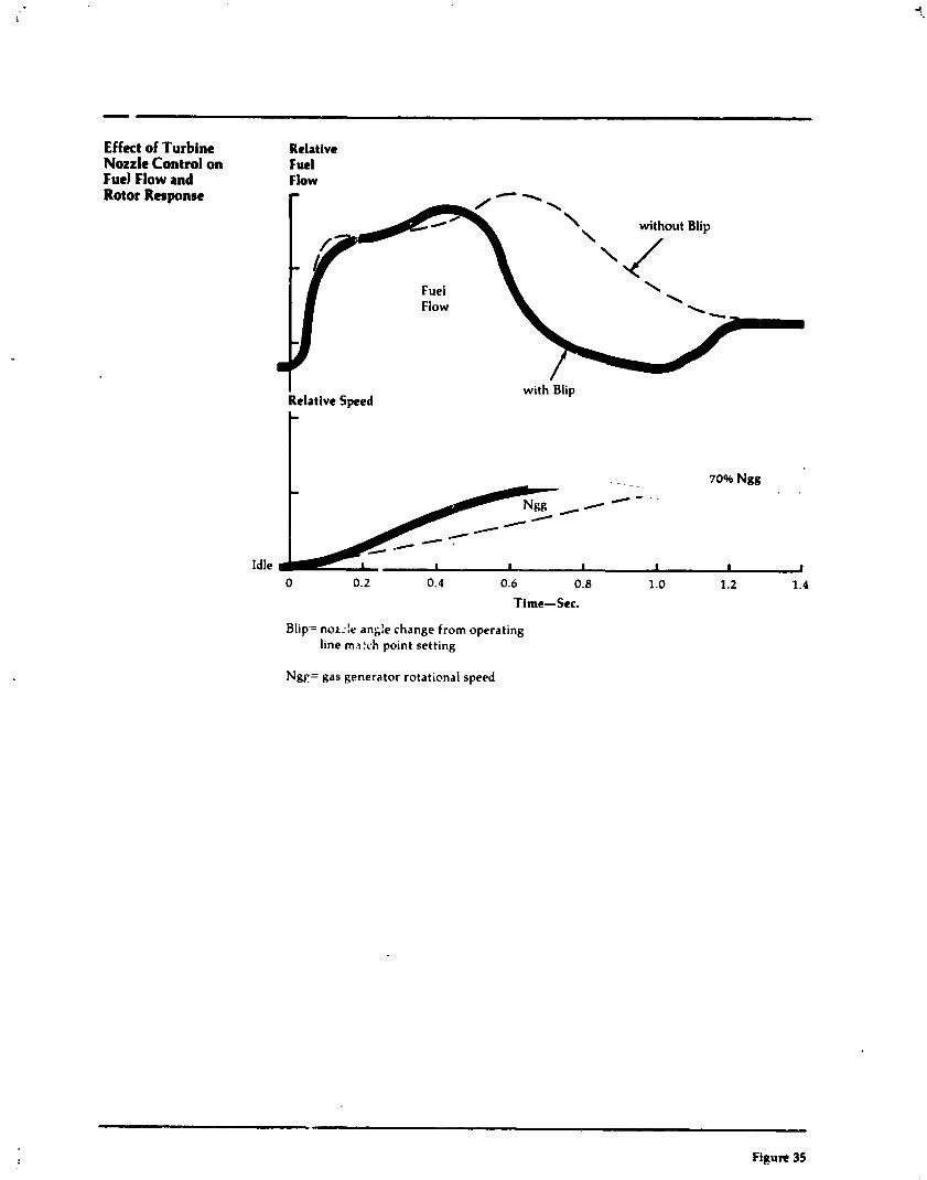
Effect of Turbine Nozzle Control on Fuel Flow and Rotor Respanre
Relative Fuel Flow
Fuel Flow
I with Blip Relative Sped
C - , - Idle I I I I I I
0 0.2 0.4 0.6 0.8 1.0 1.2 1.4
Time-Sec.
Blip.= noz-ie ang:e change from operating line m3:rh point setting
Ngc= gas generator rotational speed
Figure 35
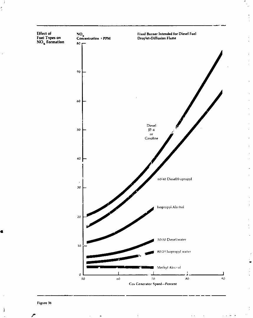
Effect of Fuel Tvpes on NO, Formation
NOx Concentration = PPM 80 P
Fixed Burner Intended for Diesel Fuel Dro~let-Diffusion Flame
lsopropyi Alcrhol
50150 D~esel lwater
4 8012ll Isopropyl water
Methyl Alccf- ol
0 50 bO 70 8 0 QO
C a 5 Generator Speed-Percent
Figure 36
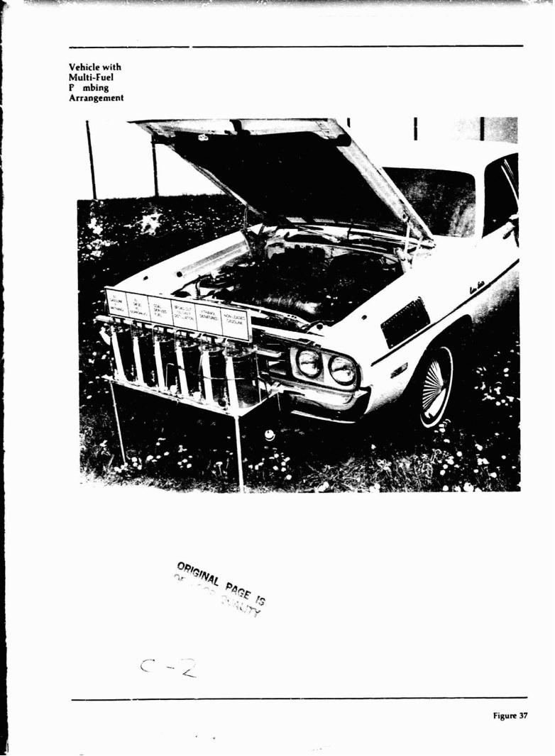
Vehicle with Multi-Fuel F mbing Arrangement
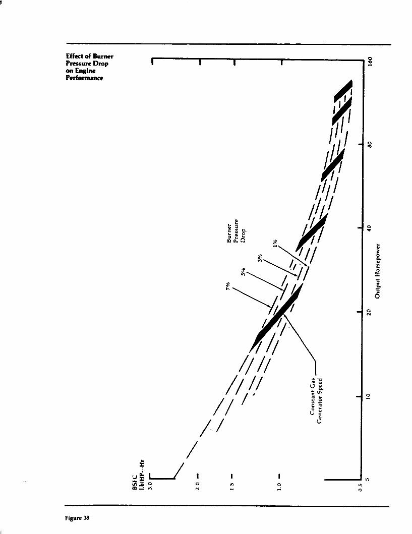
Effect of Burner P m s u n Drop on Engine Performance
Figure 38
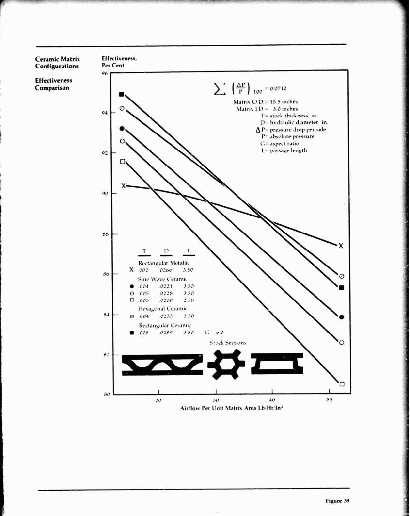
Ceramic Matrix Configurations
Effectiveness Comparison
Effectiveness, Prr Cent
Qe I
Matrix 0 . D . z 15.5 inches Matrix l .D.= 3.17 inches
T= s t tr l thickness, in. D= liydr.~ulic Jidmekr, in.
A P= pressure drop p r side r= ahscrlute pressure G= . ~ s p C t ratio
30 I I 1 t 1 ' 0 3 17 40 50
9irflow Per Unit hlatrix Area LbiHrlln2
Figure 39
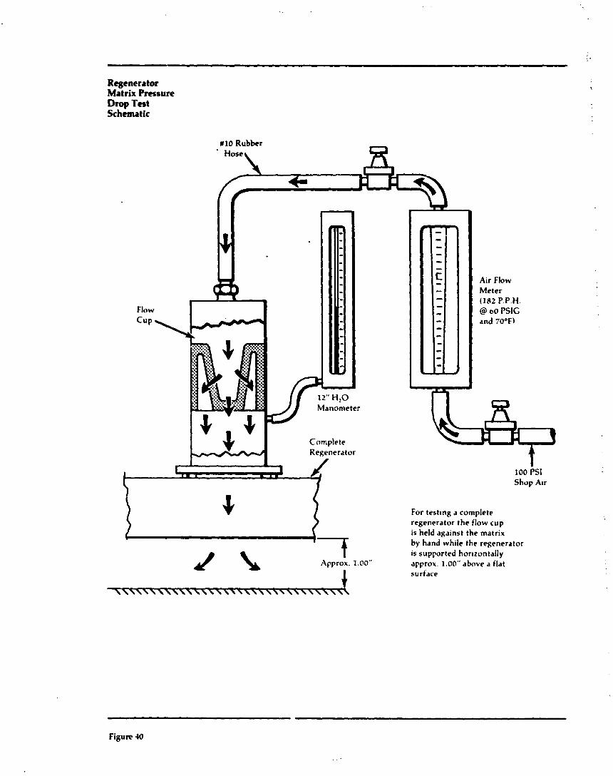
Rcgenera tor Matrix Pressure Drop Tat Schematic
I Approx. 1.00"
For t e s t~ng a complete regenerator the flow cup is held against the matrix by hand while the regenerator is supported hor~zontally approx. I .OO" above a flat surface
Figure 40
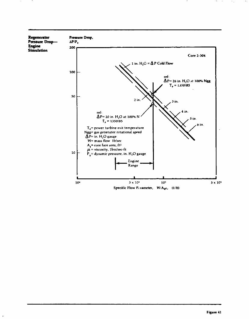
Regenemtor PmMure Drop- Eneim Simulation
5 x 10' 1 OS
Specific Flow Pi rameter, WIA*, (lift)
Pmaurt Drop, MIP" 200
100
50
10
Core 2-304
1 in. H,C = A P Cold Flow
-
-
ref: AP= 20 in. H,O at 100% N
T, = 1350185
T,= power turbine exit temperature Ngg= gas generator rotational speed AP= in. H,O gauge W= mass flow lblsec At= core face area, ftz C( = viscosity, ~bmlsec-ft - Pv= dynamic pressure, in. H,O gauge
I- Engine > Range
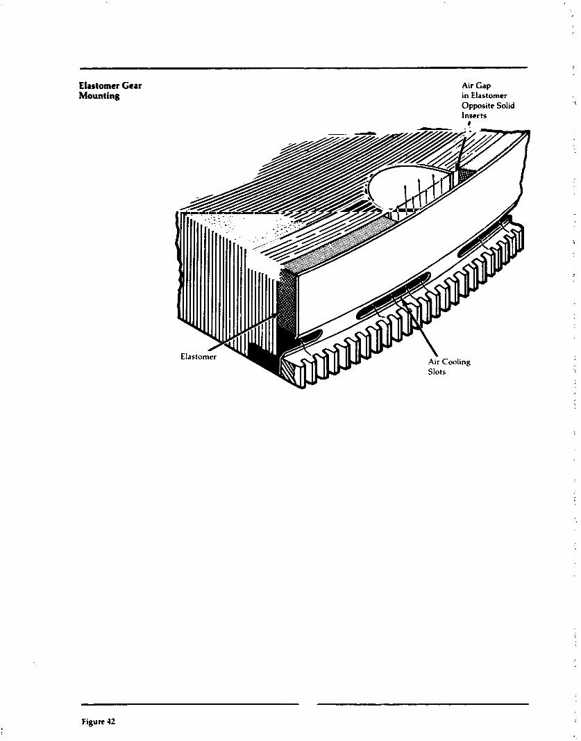
Elastomer Gear Mounting
Air Gap in Elastomer Opposite Solid Inserts
I
Figure 42
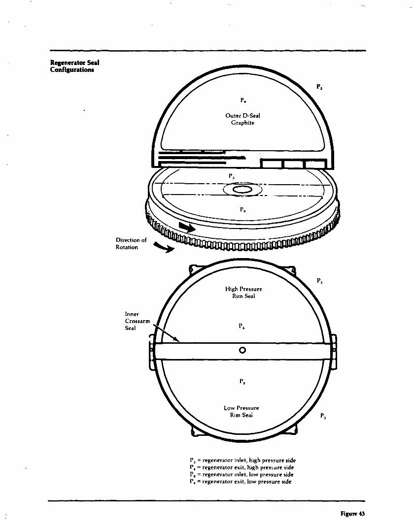
Regenerator Seal Configurations
Direction Rotation
P, = regenerator inlet, high pressure side P, = regenerator exit, high pressure side P, = regenerator ~nlet, low pressure side P, = regenerator exit, low pressure side
Figure 43
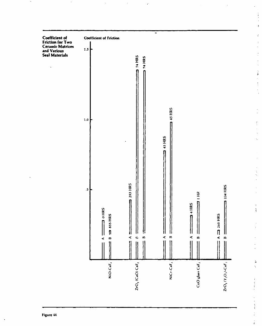
Coefficient of Coefficient of Friction Friction for Two Ceramic Matrices and Various Seal Materials
Figure 14
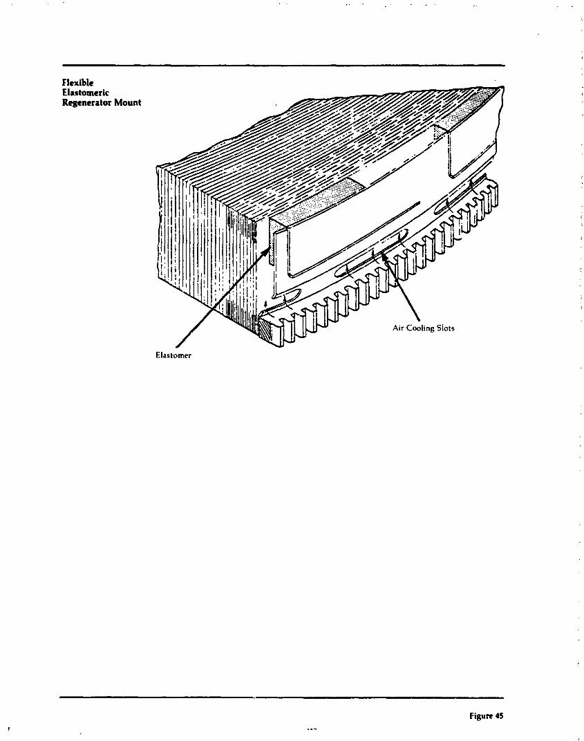
Flexible Elastomeric Regenerator Mount
Elastomer
Figure 45 . ..
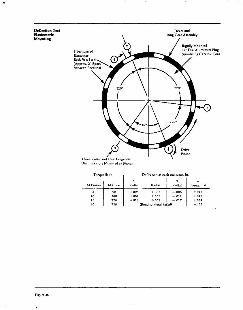

Regenerator Core Torque Characteristics
P, "Hg or % Ngg
C o n sw, RPM
Nickel 0 d d e Crossarms Against Thin-Wall " A Matrix
0 20 40 60 80 100
Core Torque, Lb-Ft
Variable I Steady Condition
Core Speed 1 . 1'4 / RPM
CoreRPM 1 1400 1 30.0 I 0 Ngg ( 123011245 (Engine Match Power)
Ts = power turbine exit temperature P, = regenerator inlet pressure, high
pressure side, "Hg gauge
-- - - - -
Figun 47

Relative Fuel Relative Flow Change with Fuel low Regenerator 1.10 Effectiveness
50% Engine Speed
.90 88 89 90 91 92 93
Regenerator Effectiveness, Per Cent
Figure 48
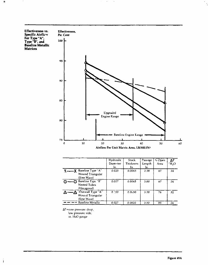
Airflow Per Unit Matrix Area, LBIHRIINZ
Effectiveness vs. Effectiveness, Specific Airflcw Per For Type " A , Type "B", and loo Baseline Metallic Matrices
95
90
85
80
75
AP=core pressure drop, low pressure side, In. 1 1 2 0 gauge
Cent
-
-
-
-
-
Baseline Engine Range #-b
I I I I I I
0 10 20 30 4G 50 60
X-X Baselitle Type "A" Wound Triangular (Sine Wave)
0 -0 Baseline Typr. "B" Nested Tubes (Hexagonal)
A-A Thinwall Type "A"
Figure 49A
Hydraulic D~arnr te r
In. 0.G25
0.027
0 .'20 W o u ~ l d Triangular (Sine Wave) -- ---- Baseline 4 Metallic 0027
Stock Thickness
In. 0.0045
0.0045
O.Ob30
0.0020
Passage Length
In. 2.58
3.00
3.70
3.50
Open Area
67
6 7
76
A P "H,O
24
24
- 3 2
85 24

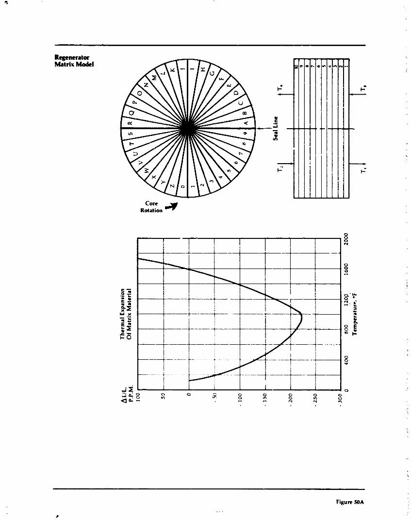
Regenerator Matrix Model
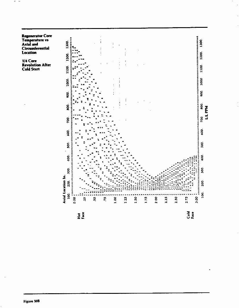
Rqpwrator Con Temperature vr Axial and Circumferentid Location
114 Core Revolution After Cold Start
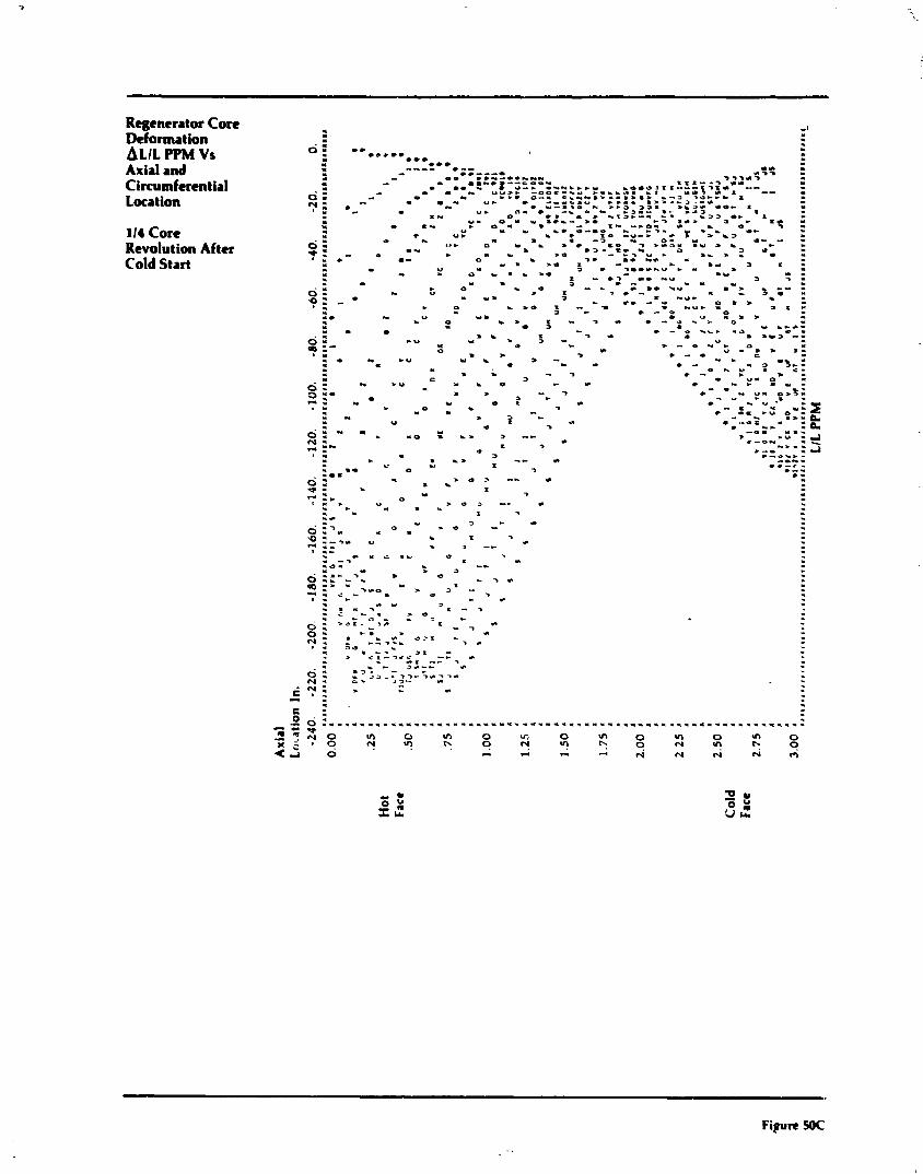
Regenerator C o n Deformation ALIL PPM Vs Axial and Cirmmfenntial Locat ion
114 Core Revolution After Cold Start
. * I
= . . L
. C O * * . .** . I *** " I ---- *a- - - ..---. L I r
I - 00 em..-o...-.. *.)- . - - . a.m.--- = 0.- .),-.--. .
I 0 0 5 0 U- - 0 C N b C . Y L O O U J I I . 0 : - - . a .. UU,. -00.2-5- .-..em .. .. ..* 0-. O........'..., - - 3 > " * - - . . . *-.. U * , --*"." *w. r . J w - c , - L Z - . Y - m . 0 I *-a .,23 .,_ w.3- 00- I *- 0 UI n- , -& e m w . 1 3
L .. .. 1 , 5..3.-. r . - 3 3 0.- I - UI O I Y .*L- w - - 3 L J . - C.. - 1- -.0. L . O u* -1- ., . .. 0--0 - - 7 . 'f :
C U. . 1 0 - u - C . : -*-., -- e I - 3 .. 0. u 0 : U- o Y w . L O -. * L a - .Y = L
0. - I -. -3- t . .. 3 U C . - b J 0 - c > U r
0.. 0 . -.* -00 ..* . ..,a 0 r
r 8 J O I . 0 " - . 3 0 -.m.*-u . . ..a 3 I .
m .I . a . . = . w e - . . - C-3 L. L.U - - 1 I . - IY 3 - 3 . . 0 0 = - - L .. .u
. I Y .. u J I 7 . - I, . - - - . I. 3 * N U -
. I 3 0 : . c r e - 0 0 . 2 . 0 . , O K - -8 . ..u. - - 3 c * - 0
a x : -I - u u. r u . . . I - -, L . 0 . t a
. I . O 3 - . - O * L * .a
Y ..a-
*" .'Ib> 5 - -, L * . w.,,=-: 0 3, .I 0 . ?: 0 . > -. * - . - u . . , I - .=
- 0 N - U U . > - C - L . . . = - -. C - . . - .
3 . 0 = - - . u- a . * - 0
5 . m u -
a % - -3 a c .. u- o w % $
Y 0 t * - . - .
, . -, Z U .= . * " O I - - - - L - - : 2 . .. * O L .U P . U - r , - 0 1 1 . . .a
-01. -I-
'*-,,-u : =! m :- I -3 ..b -.
I - Q * - 0 -4 . . . .w -.- * .-ex. - ---- U U - .a -3 C -.- .. *-- . J 0 > -. L
* - . . . I - :. 0 I -3 .
2 " . u J U , -- L . . .I l . . . .
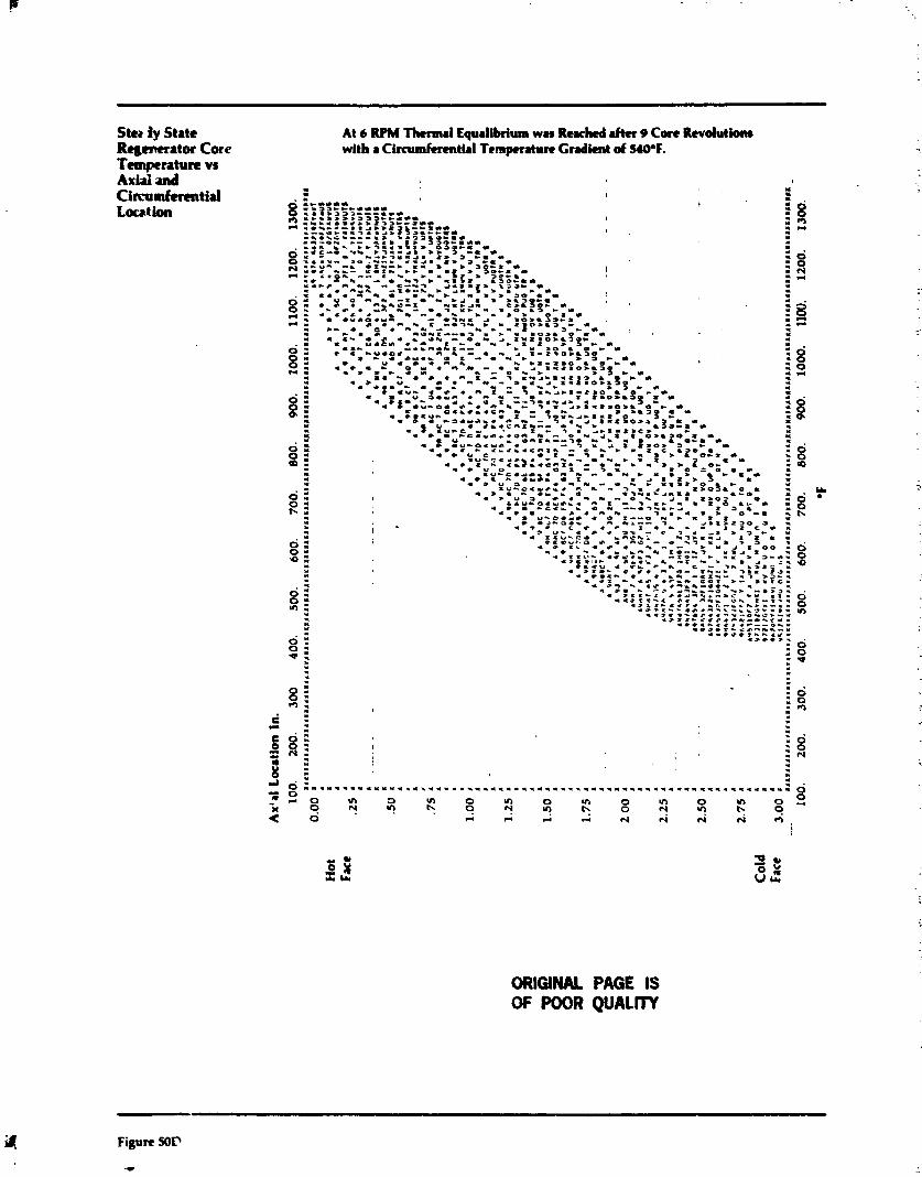
Stta iy State Regenerator Core Temperature vs Axial ud Circumferential Locat ion
At 6 RPM Thermal Equalibrium was Reached rhcr 9 Con Revdutiam with r Circumferential Temperrturn Gradient d MO°F.
ORIGINAL PAGE IS OF POOR QUALITY
Figure 50D --..
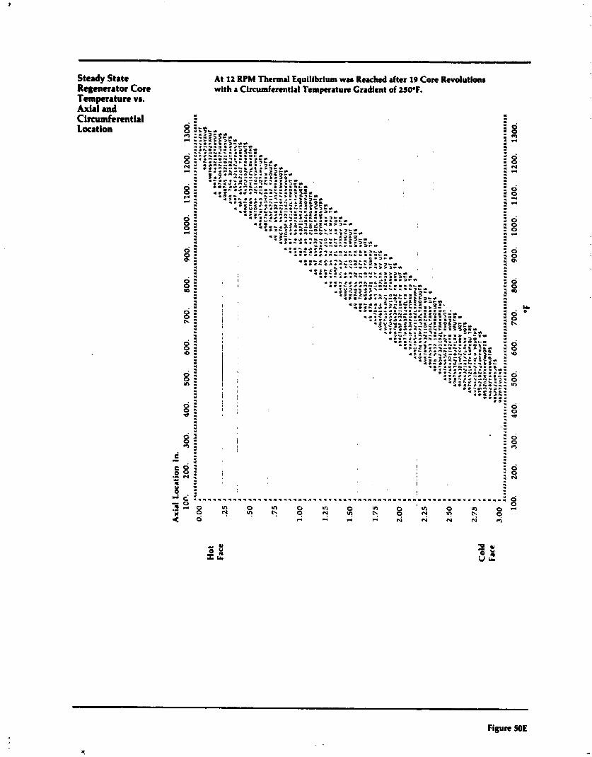
Steady State Regenerator Core Temperature vs. Axial and Circumferential Location
At 12 RPM Thermal Equilibrium was Rexhtd after 19 Con Rcvolutlanr with a Cirmmfertntial Temperature Gradient of 2S0°F.
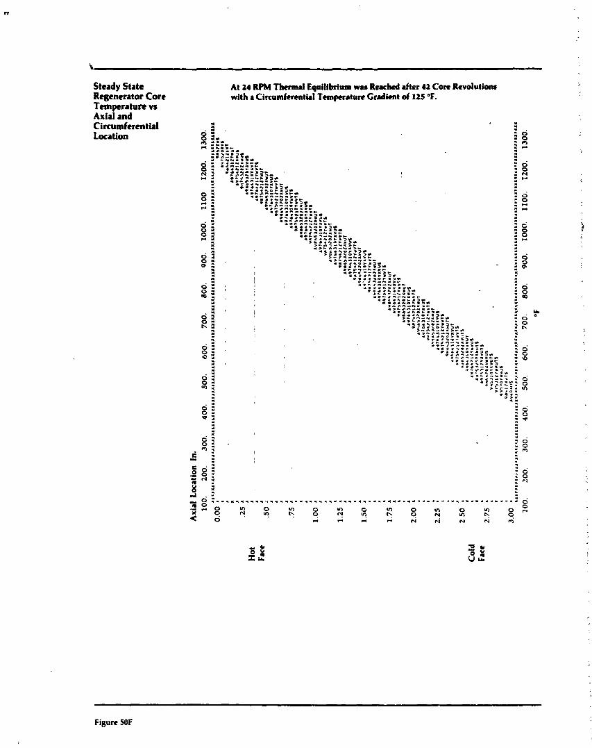
Steady State Rqgenerator C o n Temperature vs Axial and Circumferentid Location
At 24 Thermd Equi~ibrium w u Reached after 42 C o n Revolutions with r Circumferential Temperature Gradient of 125 OF.
Figure 50F
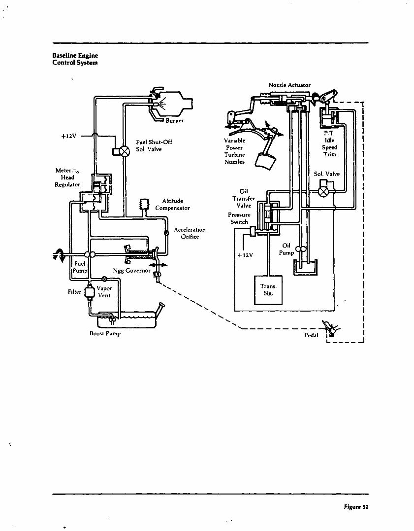
Baseline Engine Control System
. . J Boost Pump
Nozzle Actuator
Figure 51
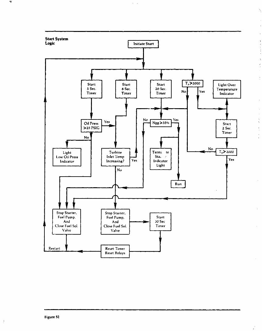
Start System Logic initiate Start L7-1
1
Timer Timer
Start 2 Sec. Timer
Low Oil Press Indicator
Stop Starter, Fuel Pump,
Close Fuel Sol. Close Fuel Sol. Valve
Reset Timer
Figure 52
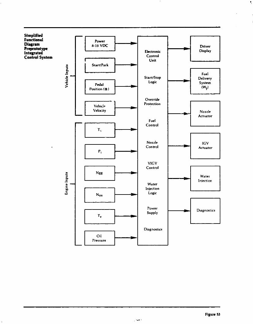
Simplified Functional Diagraln Reprototype Integrated Control System
Figure 53
Electronic Control
Unit
StartlStop
- ,
Display Driver
Power 8-15 VDC -I StartlPark El-
Fuel Delivery
Pedal Position (a)
Logic w
System (Wf)
1
Vehicle Velocity -I
Override
I
Nozzle Control
VlGV Control
Water Injection
- L
PI
Protection
Fuel Control
T, *
IGV Actuator - Act~rator Nozzle
Nos
Ngg
- - Logic
* Water
Injection
D~agnostics
EI- Power Supply
Diagnostics
Pressure
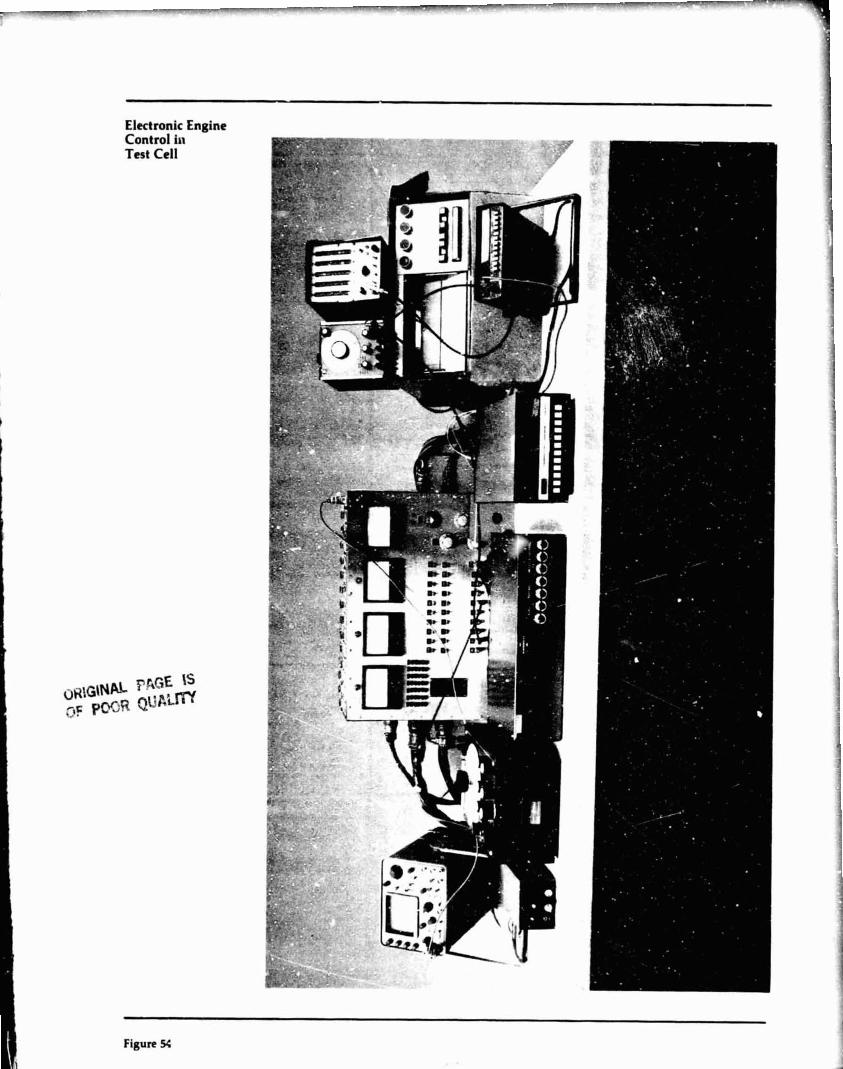
Electronic Engine Control iri Test Cell
Figure 54
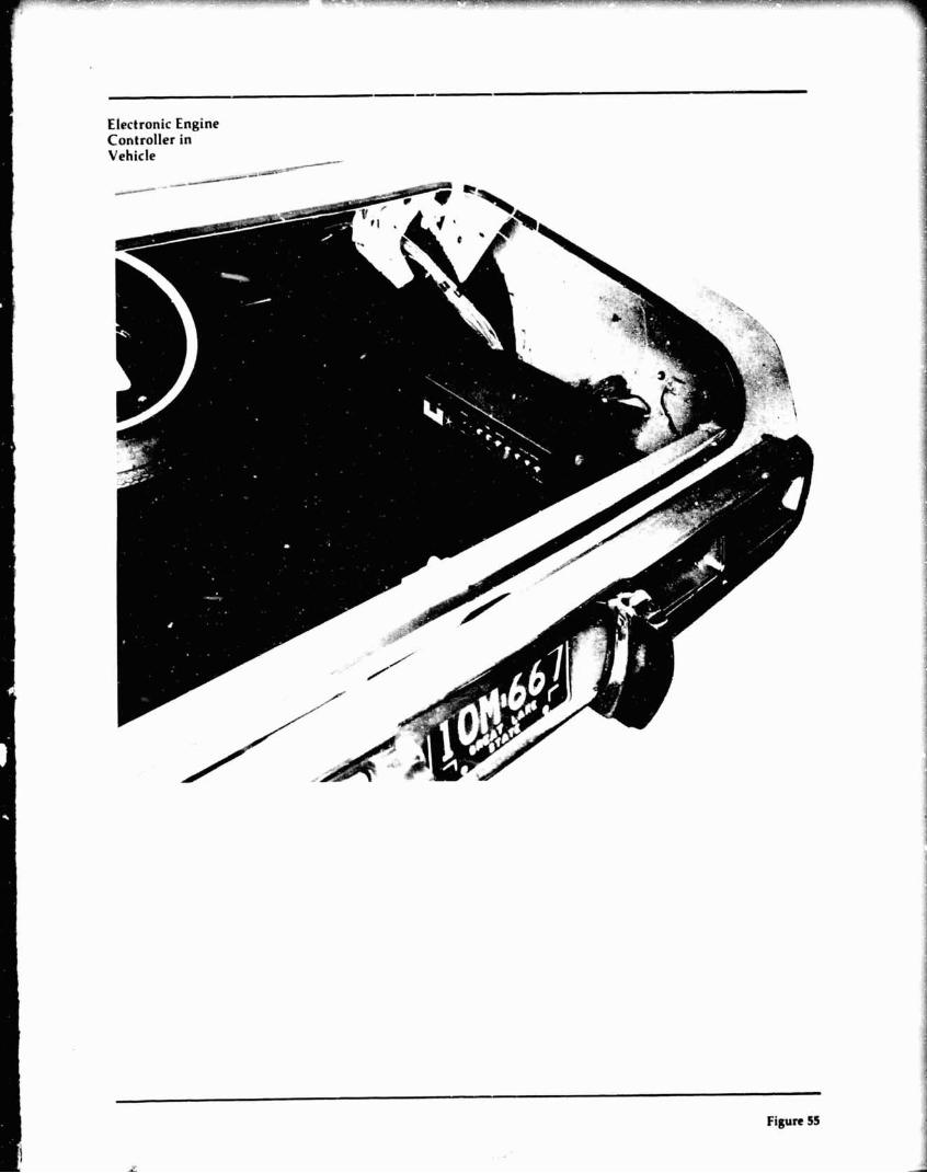
Electronic Engine Controller in Vehicle
/-
Figure 55
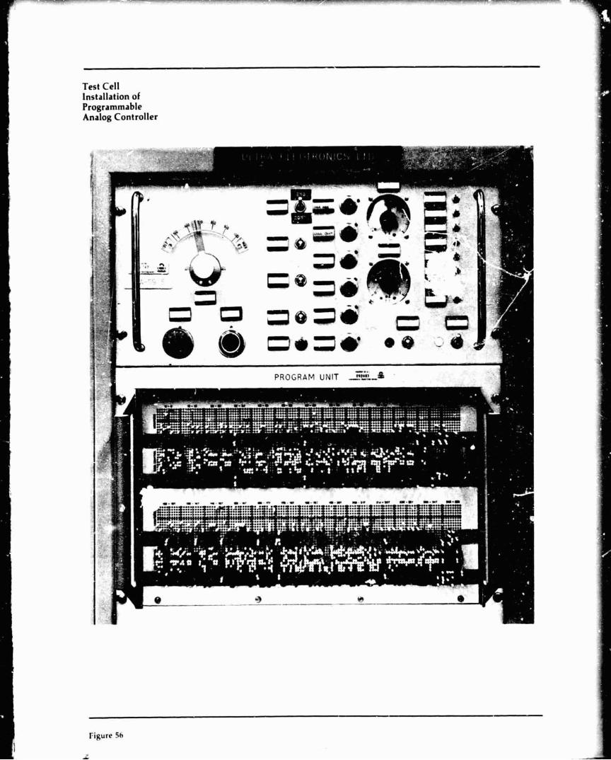
Test Cell Installation of Programmable Analog Controller
Figure Sh
L

AiRwarch Fluidic Temperature S c m r Tcrb
Output Frequency M. Tempenhut
Frequency, Hertz
PP 106-171 BN sensor with piezoceramic transducer, 3 psi air
0 stalled propshaft
1000 rpm
I 1900-2000 rpm
Temperature, OF.
Figure 57
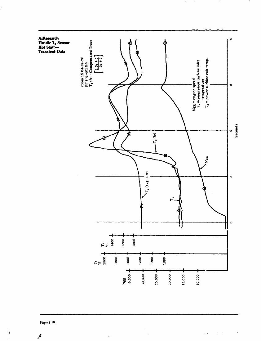

AiReeeuch Fluidic T8 Sensor Awl-Tmrimt Data

AiRcc~lrch Fluidic T, !knsor Dml-Transient Data
Figure 60
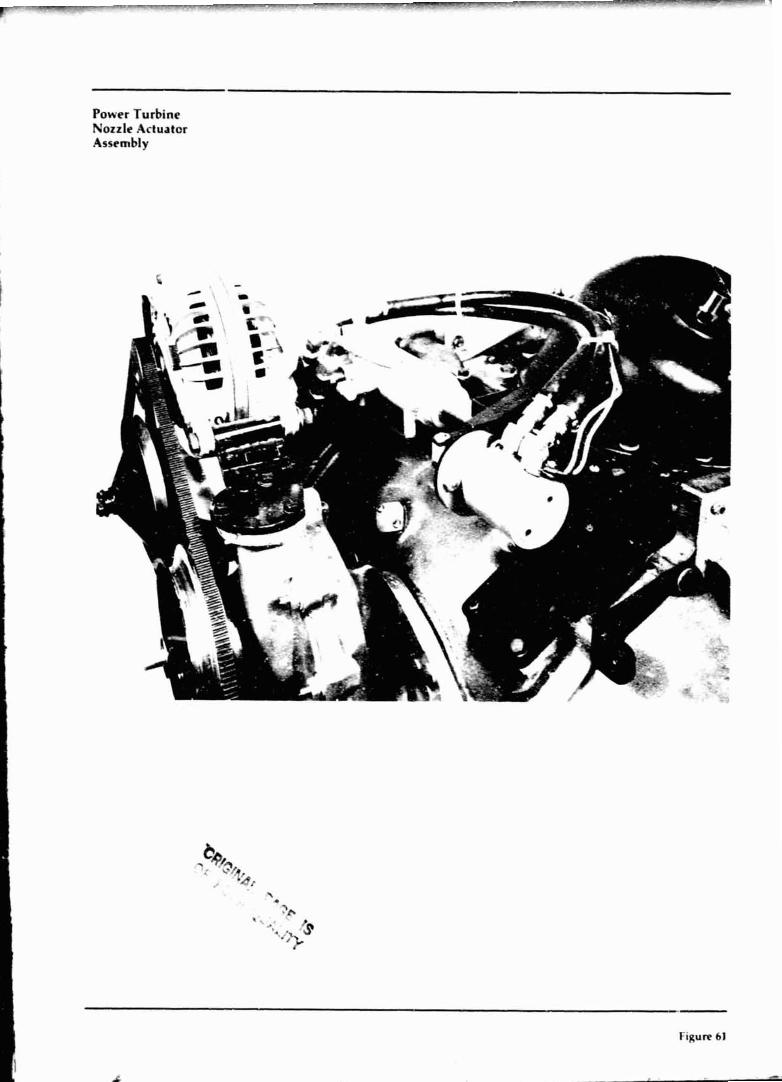
Power Turbine Nozzle Actuator Assembly
Figure 61
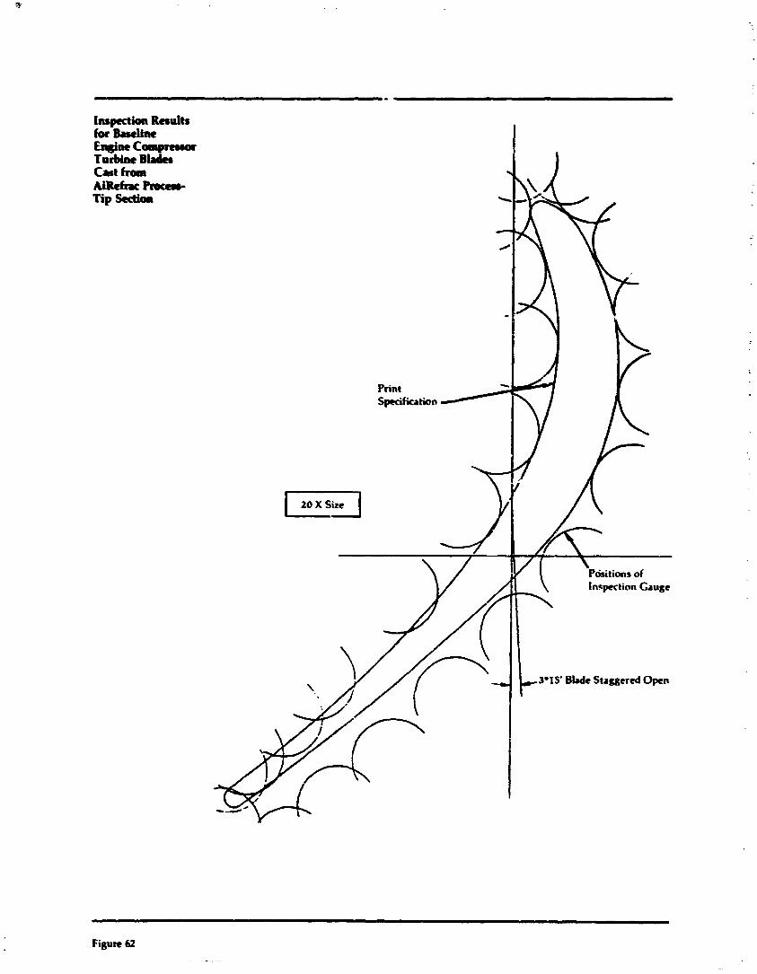
Inspection Results for W i n e EWm compnrww Turbine B b Cat from AUcfrwmcem- Tip sectha
I 20 x size I
Print Spuifiution
. Pdritions of Inspection Gauge
\
3.15' Blade Staggered Open
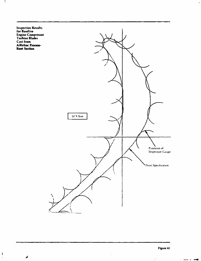
Inspection Results for Baseline Engine Compressor Turbine Blades Cast from Aiiefmc RDCICbb- Root section
20 Y Size E I
Figure 63
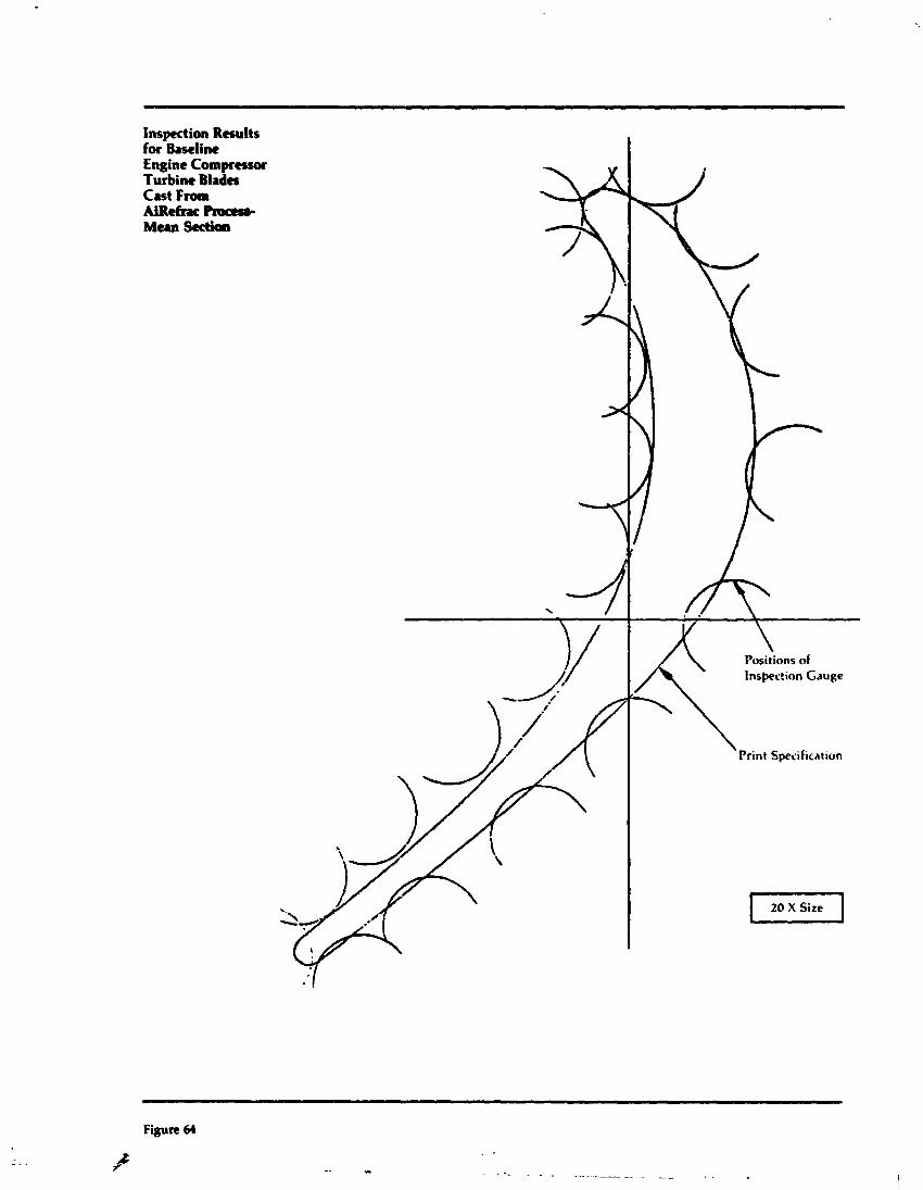
Inspection Results for Baseline Engine Compmror Turbine Blades Cast From AiRthcPmas8- Mean Scctioa
Figure 64
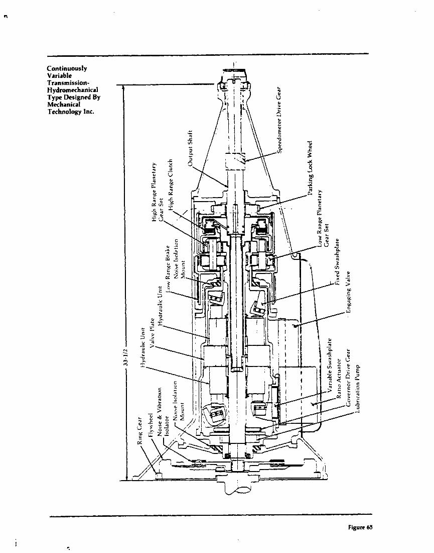
Continuously Variable Transmission- ~~dromechanical Type Designed By Mechanical Technology lnc.
Figure 65
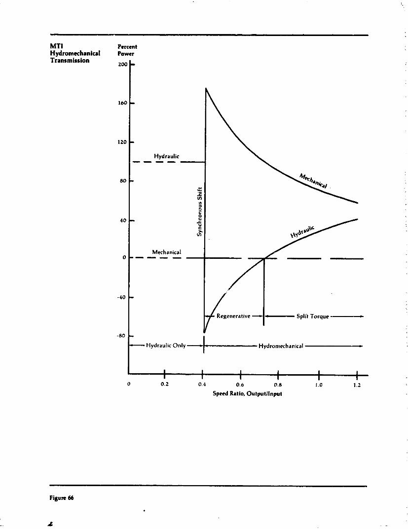
NIT1 Hydromechanical Transmission
Percent Power
-" 1 Hydraulic Only Hydroniechanical L
I I 1
I I
I I
I I
I I
I I
0 0.2 0.4 0.6 0.8 1 .O 1.2
Speed Ratio, Outputllnput
Figure 66
J
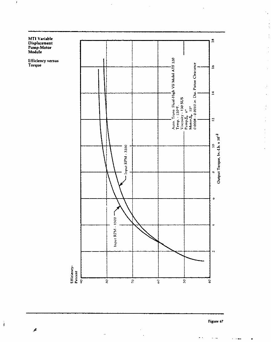
MTI Variable Displacement Pump-Motor Module
Efficiency versus Torque
Figure 67
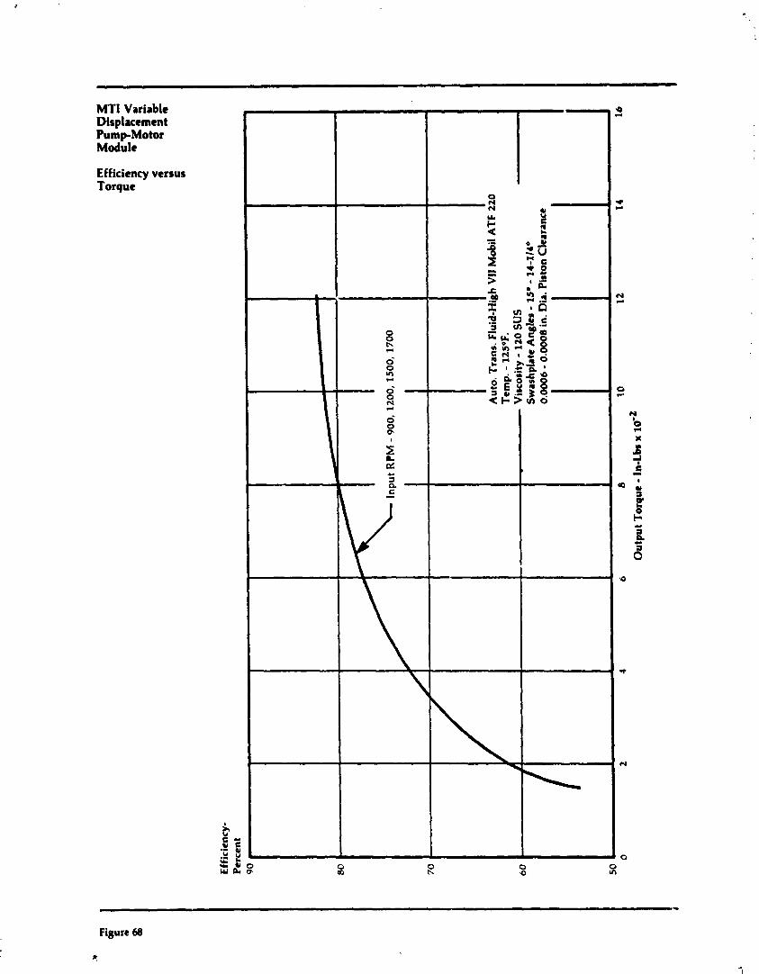
MTI Variable Displacement Pump-Motor Module
Efficiency versus Torque
Figure 68
IC.
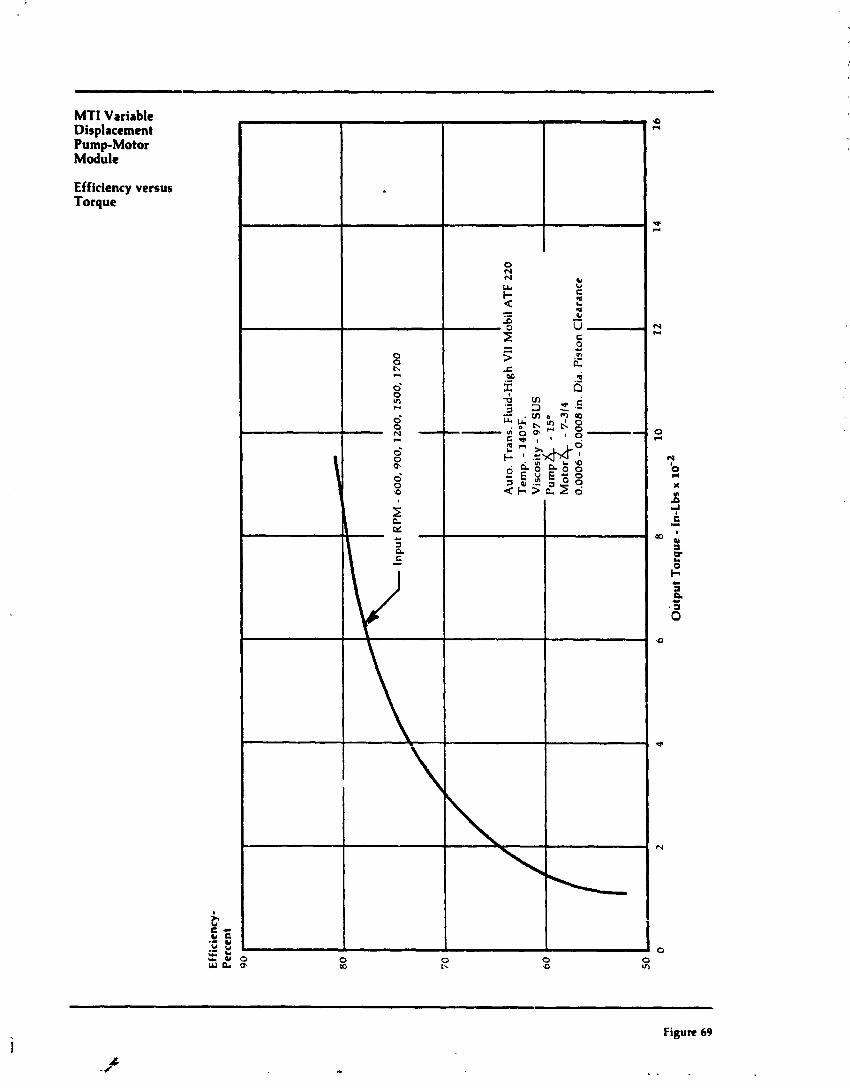
Eff
icie
ncy
- P
erce
nt
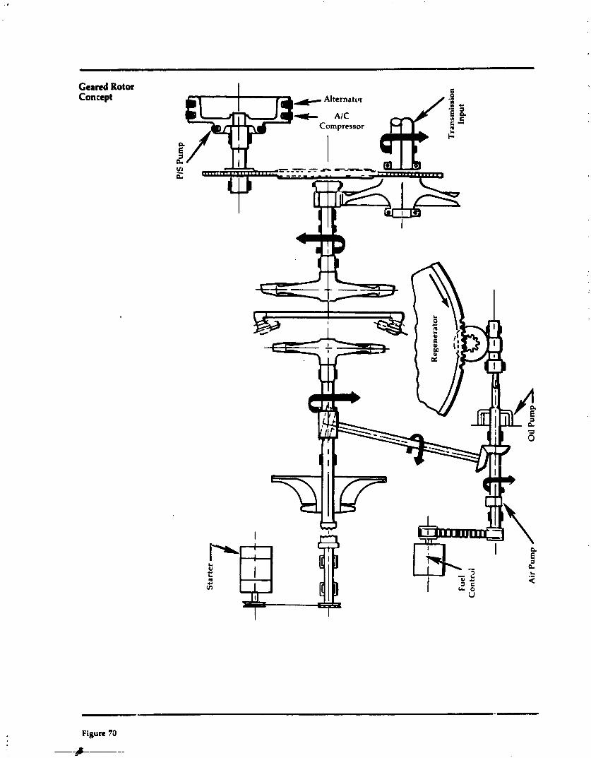
Cerrd Rotor Concept
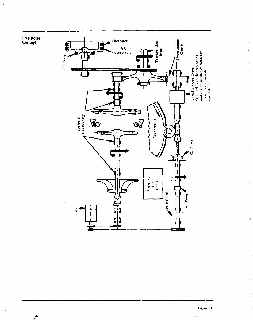
Free Rotor Concept
- Figure 71
k h . /
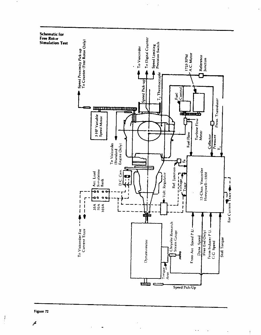
To
Vis
ico
rder
Fo
r ---L - - -
Cu
rre
nt
Tra
ce
I) - -
- -1
7
1 I
I
Sp
eed
Pro
xim
ity P
ick-
up
T
o C
ou
nte
r (F
ree
Ro
tor
On
ly)
35A
A
cc.
Lo
ad
S~
f~u
lati
on
7
0A
R
ank
103A
To
Dig
ita
l Co
un
ter
T In n 3 2 C
Fro
m A
cc
Spe
ed P
.U.
'u
12-C
han
. Vis
~co
rder
Ho
neyw
ell-1
508
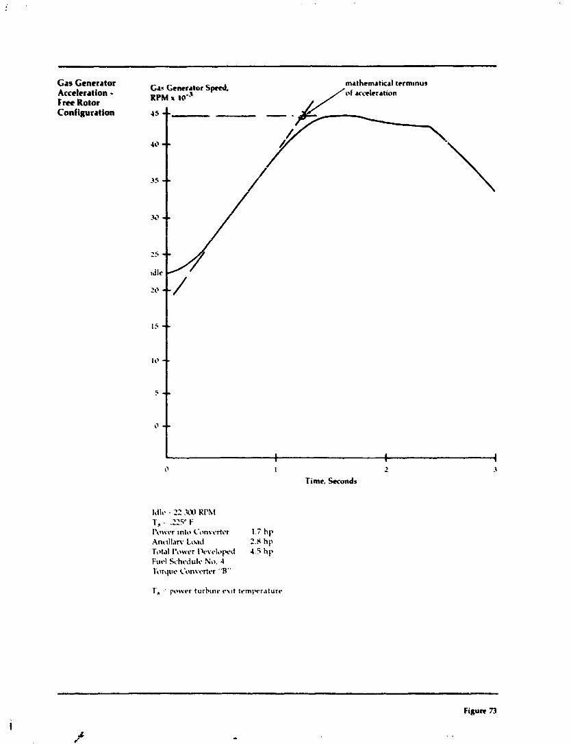
Gas Generator Acceleration - F m Rotor Configurat ion
I > - Time, Seconds
I ~ ~ I C . - 22 xw T, - .22Y F I'trwt-r ~nta C'nnvtsrtcr 1.7 hp tlnc.~ll.~rv L c ~ 2.8 hp Tot.~l I'trrvt-r I)cvt-l~pt-~l 4.5 hp Fuzl Schcdult. No. 4 'Llrqrlt- L'onvertt-r "B"
Figure 73
tC

Variation d Eqim Operati- Line with Accelcratton Time
b u r r Ratio PJP,
1 00 1 1 1 I 1 0 1) 1 1'3 I 4 0 1 $0 2 20 2 03
Airflow LBlSEC
Figure 74
4 .'

Rqptratw Utilization Fwtor

Ch
ain
Ten
rio
ner
1 .-A
-
App
roac
h A
ng
le
7
Clu
tch

Cold Start- F m Rotor Engine
Figure ?7

Turb
ine
Inle
t T
emp.
= 9
00D
F.
(1850°F
Peak
Du
rin
g A
ccel
)
I Ngg
= g
as p
ener
ator
rot
atio
nal
spee
d
No
exc
itat
ion
to
dyn
amom
eter
.
Oil
Pre
ssu
re
- 20
Gas
G
ener
ator
Sp
eed-
R
PM
- 6
0
C
25,000 -
Outp
ut or
Acc
y Sh
aft S
peed
20,000 -
RPM
-
- 15
00
15,000 -
- 1000
10,000 -
- - 5
00
I0
I
10

Enpine Performance Map
Free Rotor Configuratiol:
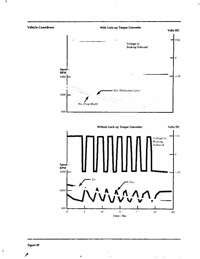
Vehicle Coastdown With Lock-up Toque Converter Volts DC
Speed-
- - ,, -. ' Voltage to
Braking Solerloid
Without Lock-up Toque Converter \'oIts UC
1030
500
7 Nos (Reduction G e a ~ ) - f .
Nv (Prop Shaft\
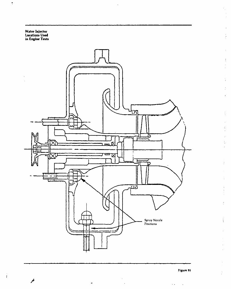
Water Injector Locations Used in Engine Tests
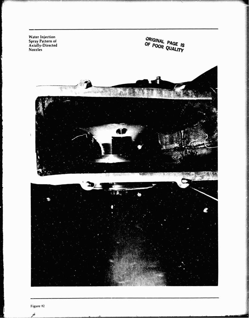
Water Injection Spray Pattern of Axially-Directed Nozzles
Figure 82
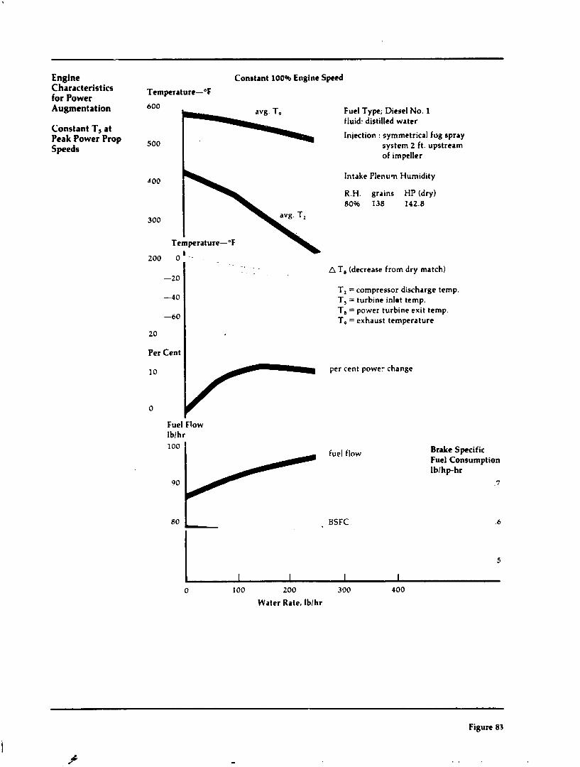
Engine Constant 100% Engine Speed Characteristics Temperature-"F for Power Augmentation
Constant T, at Peak Power Prop Speeds
Fuel Type; Diesel No. 1 fluid: distilled water
Injection : symmetrical fog spray system 2 ft. upstream of impeller
'I 00 Intake Plenum Humidity
R.H. grains HP (dry) 80% 138 142.8
300
Temperature-OF
-20
-40
-60
20
Per Cent
A T , (decrease from dry match)
T, = compressor discharge temp. T, = turbine inlmt temp. T, = power turbine exit temp. T, = exhaust temperature
10 per cent power change
0
Fuel Flow lblhr 100 1 Brake Specific
Fuel Consumption lblhp-hr
7
BSFC 6
0 100 200 300 400
Water Rate, lblhr
Figure 83
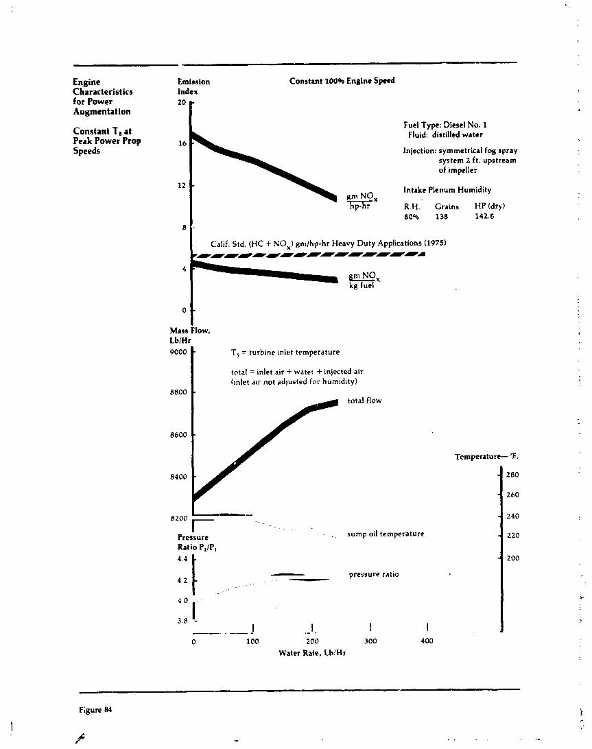
Engine Emission Constant 100% Engine S p e d Characteristics Index for Power 20 r Augmentation
Fuel Type: Diesel No. 1 Constant T, at Fluid: distilled water Peak Power Prop Speeds Injection: symmetrical fog spray
system 2 ft. upstream of ~mpeller
12 - Intake Plenum Humidity gm NO, hp-hr R H Crams t ip (dry)
8006 138 142 E 8
Cal~f Std. (HC + NO,) gmlhp-hr Heavy Duty P.ppl~cat~ons (1975) m m - - - - - - - - 4
gmox kg fuel
0 - Mass Flow, LblHr 9000 T, = tu rb~ne ~nlet temperature
tctaI= ~nle t alr + water + lnlected alr (Inlet alr not adjusted for h u m ~ d ~ t y )
8800 - total flow
8600 -
- 8200 r
Pressure sump 011 temperature
Ratio PJP,
- pressure ratlo 4 2 '-
0 100 200 300
Water Rate, I.blHr
Tcmperature- "F.
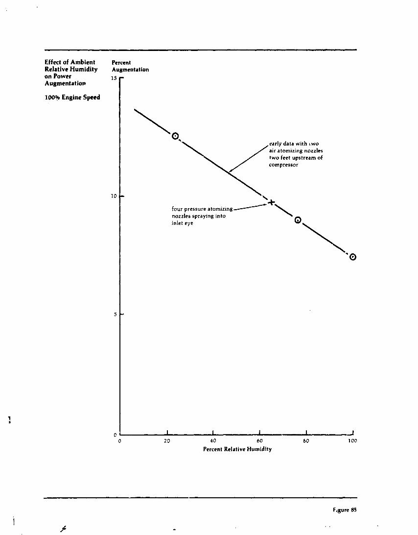
- Effect of Ambient Percent Relative Humidity on Power 1s Augmentation
100% Engine Speed
10
5
C
Augmentation -
\ 0, \/
early data with two air atomizing nozzles two feet upstream of compressor
- \
four pressure atomizing/ nozzles spraying into inlet eye
+\
O\ '0
-
I I I I J 0 2 3 4 0 60 b0 100
Percent Relative Humidity
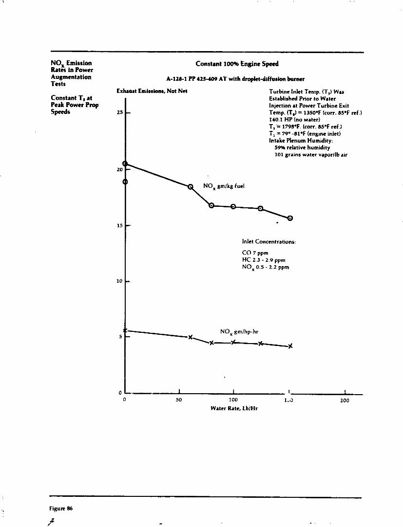
Figure 86
k P-
NO, Emission Constant 100% Engine Sped Rates in Power Augmentation A-128-1 PP 425- AT with droplct-dffusion burner Tests
Exhamst Eutissions, Not Net Turbine Inlet Temp. (T,) Was Constant T, at Peak Power Prop speeds 25
Established Prior to Water Injection at Power Trirbine Exit - f emp. ( f ,) = 1350eF (corr. 8SeF ref.) 140.1 HP (no water) T, '= 1795°F. (corr. 85°F ref.) i, = 79" -81°F (eng~ne inlet) Intake Plenum Humidity:
59% relative humidity 101 grains water vaporllb air
15
10
0
- lnlet Concentrations:
CO 7 ppm HC 2.3 - 2.9 ppm NO, 0.5 - 2.2 ppm
-
v
s':-x NO, gmlhp-hr
1%-h \%
-- 1 1 'I 0 50 100 1-3 200
Water Rate, LblHr
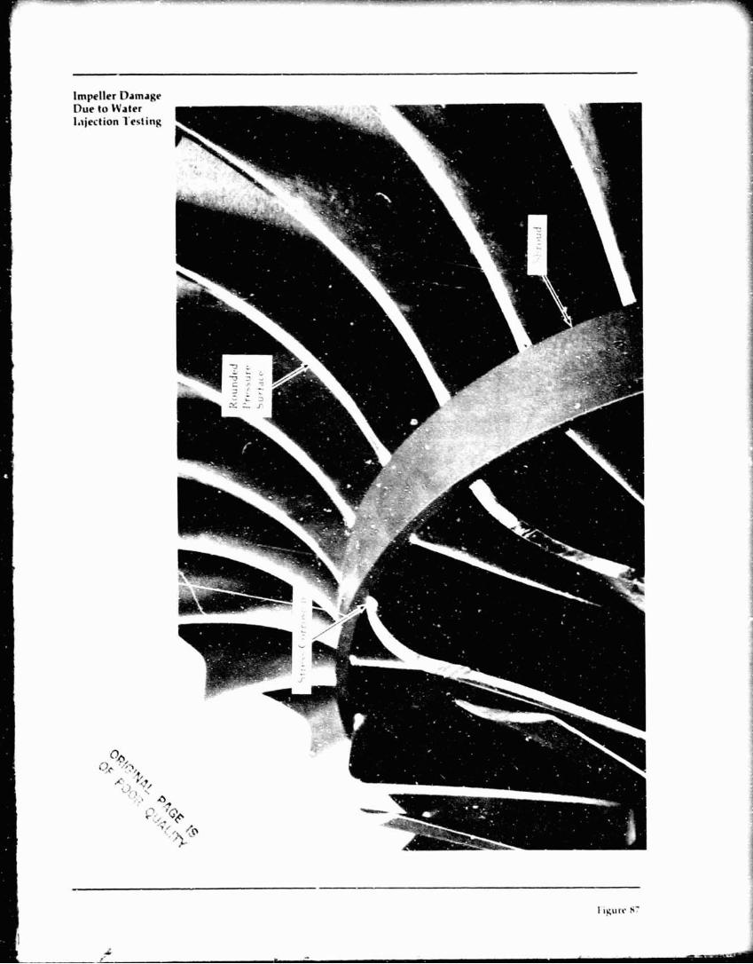
lam ter ;'ed
':', .4,
i r.
,'.I - _ I
'a?
tin
f/
C
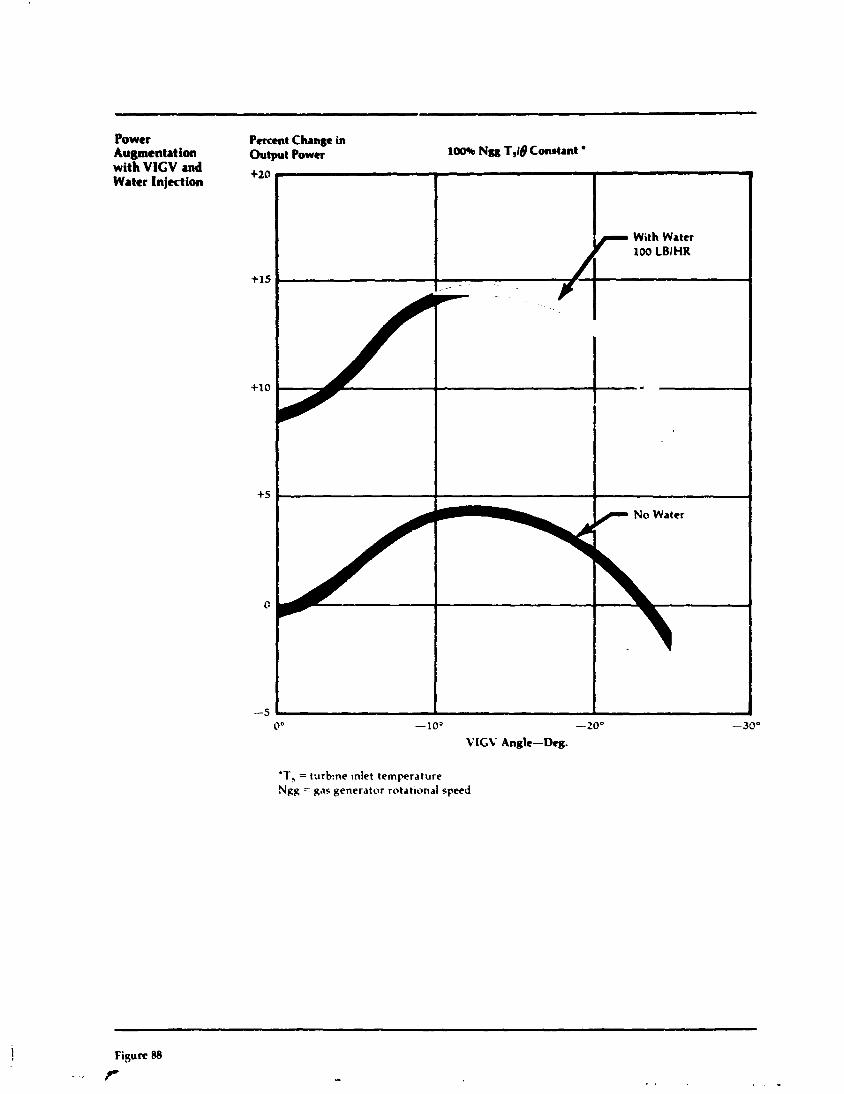
Power Percent Change in Augmentation Output Power 100% Nm T,I@ Constant ' with VICV and +20 Water Injection
+15
+10
+5
-5 0" -10' -20" -30"
VIGV Angle-Kkg.
'T, = turb:ne ~nlrt temperature Ngg = gas generator rotational speed
With Wattr 100 LBiHR
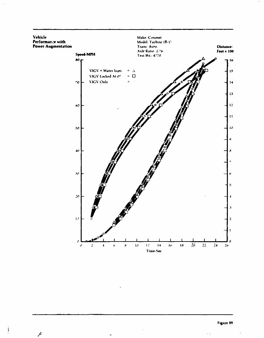
Vehicle Performm:e with Power Augmentation
hiahc: Coronet M d c l : Turkne (5-1; Trans- Auto. .\dc Ratw : . y e
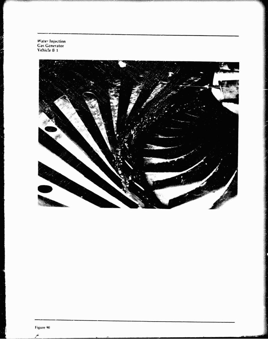
Figure 90
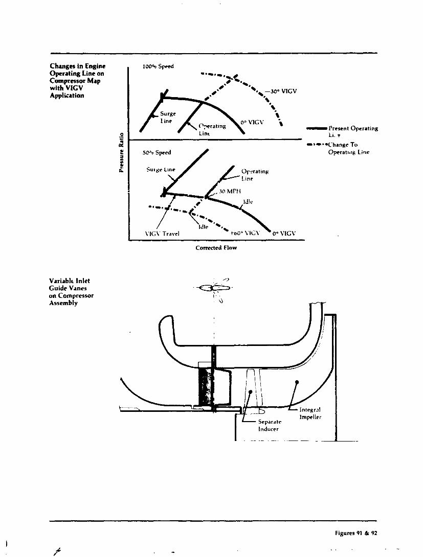
Changes in Engine Operating Line on Compressor Map with VIGV Application
Variablt Inlet Guide Vanes on Compressor Assembly
- - - - - --
, 100% Sped
- Present i i . c 0 .- - , rn
Operating
To
-'-"'-~' .* --M0 VIGV .*.
surge *\. Line
1 0- VlCV
P y r a t i n g lo-,* Lint
--
Corrected Flow
t 1 m m
2 eL
Impeller - Separate
SC% Speed Operat~h~p Line
\'lG\' Travel
I inducer
- -- . -
--- - - - - -- -- - -
Figures 91 & a2
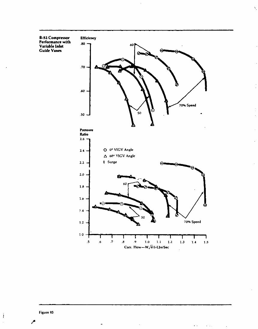
8-52 Compressor Performance with Variable Inlet Guide Vanes
Efficiency
0 0" VlGV Angle
A 60" VlGV Angle
I Surge
60
70% Speed
Figure 93
.& P-
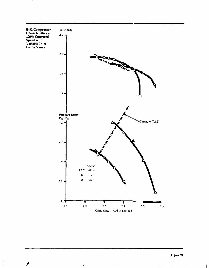
8-52 Compressor Characteristics at 100Yo Comcted S p e d with Variable Inlet Guide Vanes
Efficiency
2 1 2 2 2 2 2 4 2 5 2 6
Corr. Flow-W jHlS-~bs:Sec
Figure 94
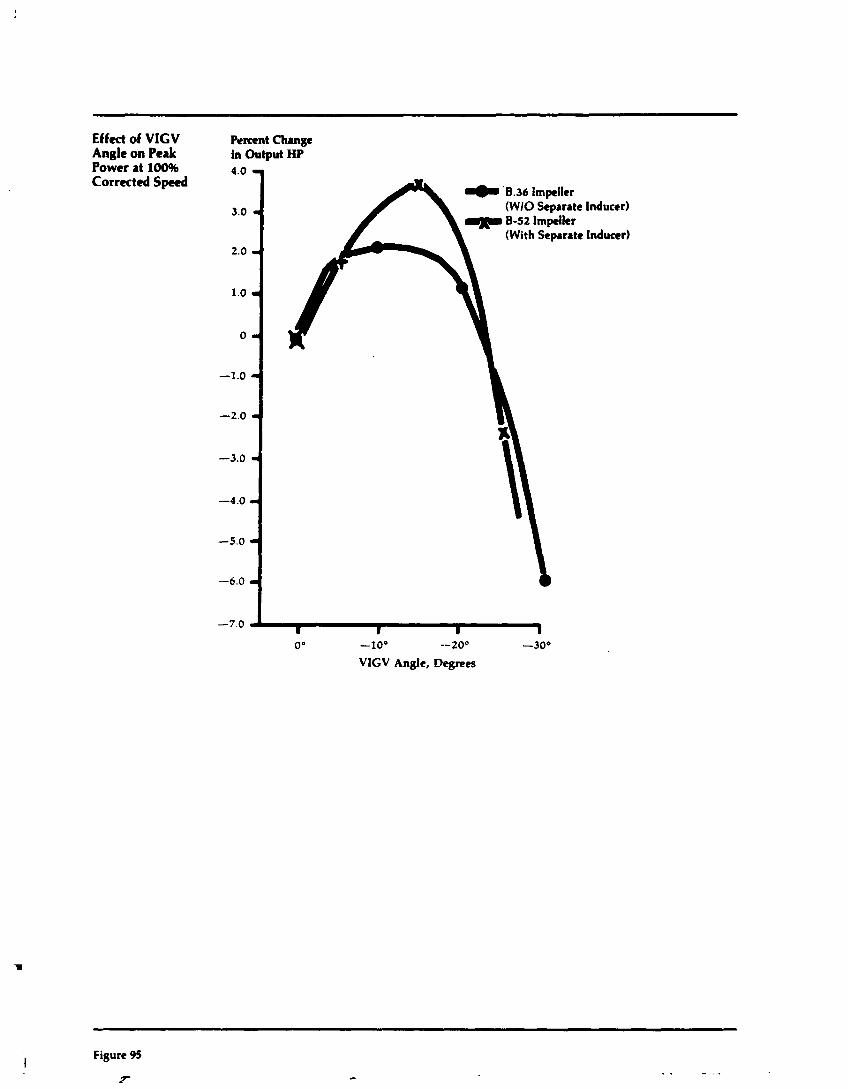
Effect of VICV Angle on Peak Power at 100% Corrected Speed
-7.0 &I oO -lo0 --20° -30'
VIGV Angle, Degrees
Pvmnt Change in Output HP
Figure 95
F
4.0 q
3.0 a
2.0 - 1.0 - 0 -
-1.0 - -2.0 - -3.0 r
-4.0 r
-5.0 - -6.0 r
(With Separate Inducer)
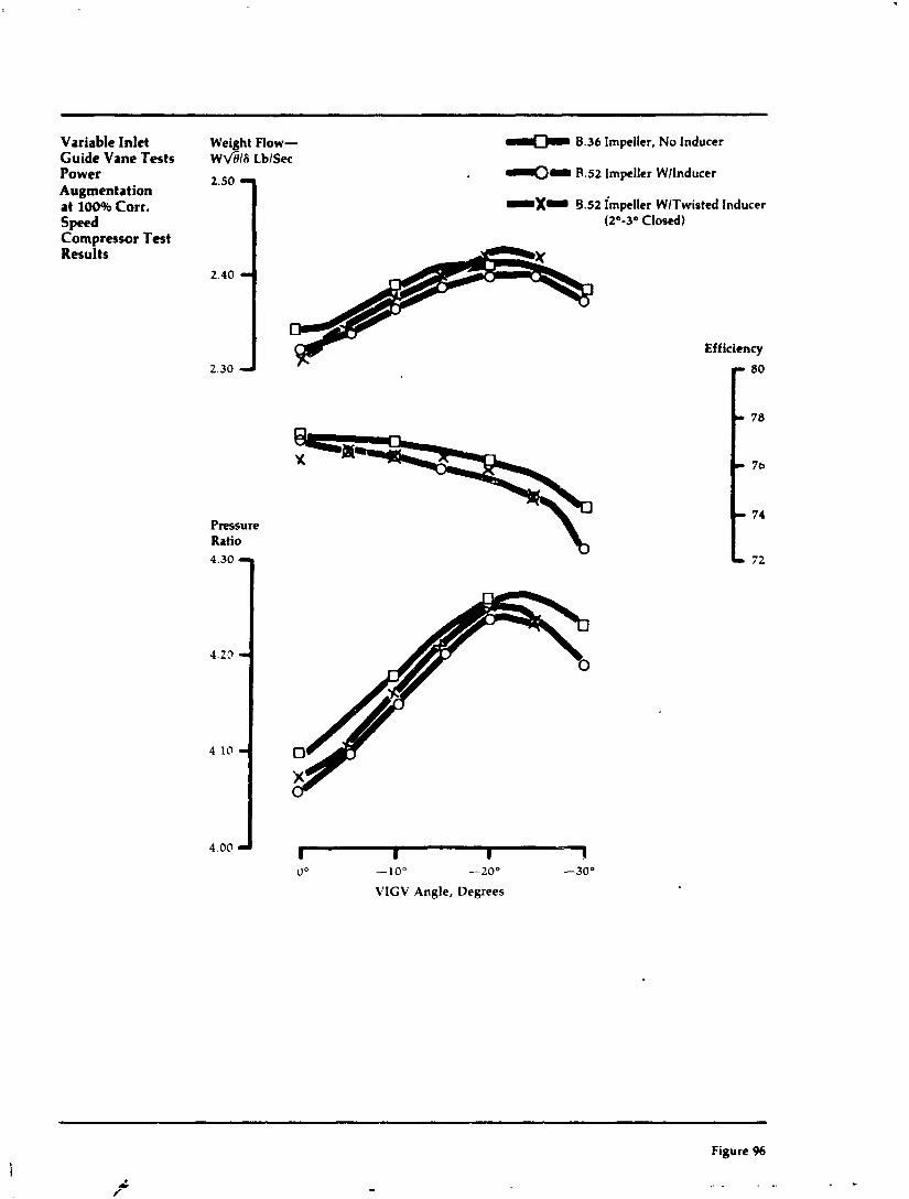
Variable Inlet Guide Vane Tests Power Augmentation at 100% Corr. Speed Compressor Test Results
Weight Flow- ~ \ / B l f i LblSec
2.50 7
B.36 Impeller, No Inducer
. e.52 Impeller WlInducer
9.52 impeller WlTwisted Inducer (2O-3O closed)
Ratio
4.00 I I I 4 u o -lo0 -200 -300
VIGV Angle, Degrees
Efficiency
- --
Figure %
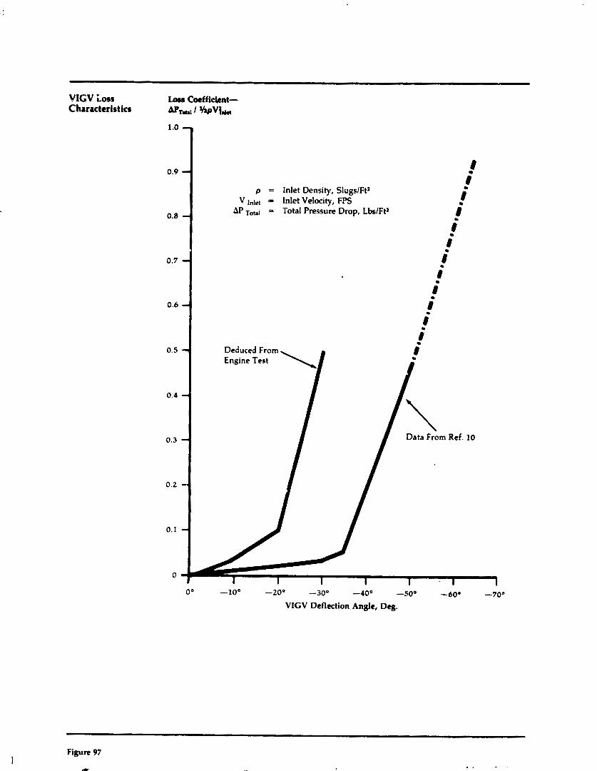
VIGV Loss Loss Cocffi&nt- Characteristics I w%,,
P = Inlet Density, SlugslFt' V I,], = Inlet Velocity, FPS
AP T O ~ I a Total Pressure Drop, LbslFt2
Deduced From Enainr TOG+ \ I
VIGV Deflection Angle, Dq.
Figure 97
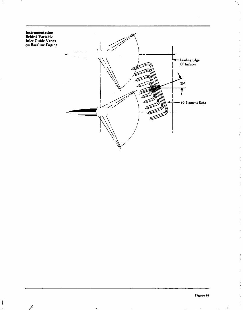
Instrumentation Behind Variable Inlet Guide Vanes on Baseline Engine
I I+ Leading Edge
Rake
Figure 98
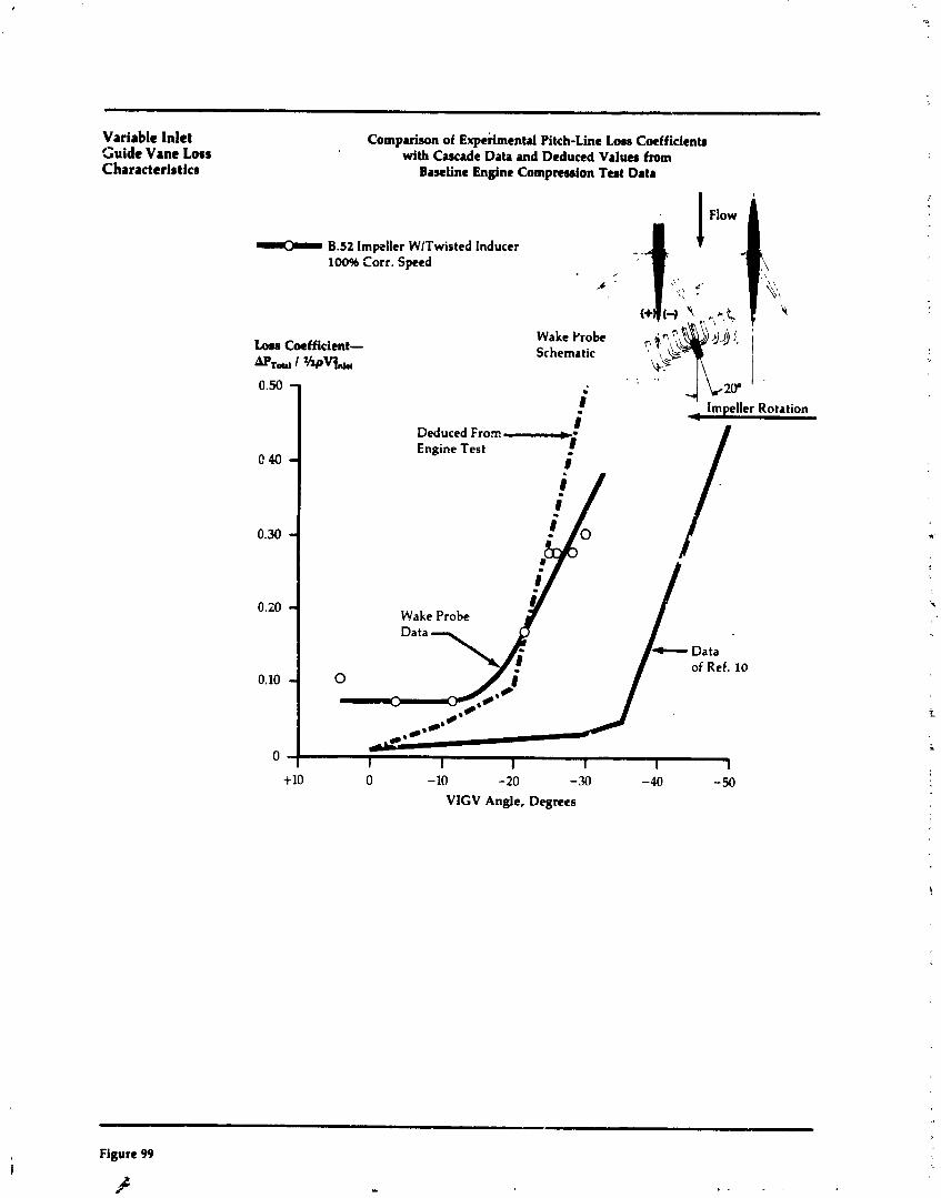
Variable Inlet Guide Vane Loss Characteristics
Comparison of Experimental Pitch-Line Lose Coefficienb with Cascade Dab and Deduced Values from
Baseline Engine Compression Teat Data
B.52 Impeller WlTwisted Inducer 100% f orr. Speed
Wake Probe $;$,'($ Schematic \ ,&--
b?
8 Deduced Fro= + - Engine Test - 8
Wake Probe
Data of Ref. 10
+10 0 - 10 -20 -30 -40 -50
VIGV Angle, Degrees
- Figure 99
A / .. , . . ,
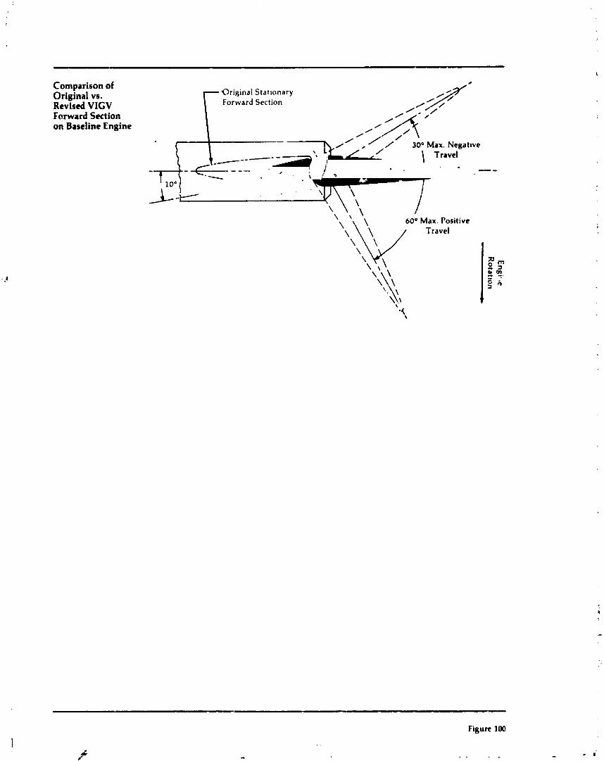
Comparison of Original vs. Revised VIGV Forward Section on Baseline Engine
Orip,lnal Statlonary Forward Section
60° Max. Positive
Figure 100
. ~
.& #'
,, . . .,
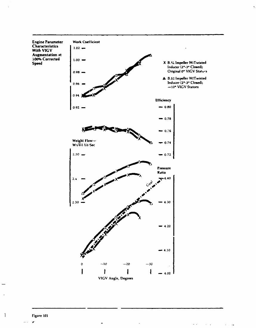
Engine Parameter Work Coef ticicnt ~haracttristics With VIGV I 1.02 0
Augmentation at 20096 Corrected 1.00 - speed X B.5; lmpeller WlTwisted
Inducer (2'-3- Clod) ; 0.98 - Original 0° VlGV Statues
A B.52 Impeller WlTwisttd
0.96 - Inducer (2.-3- Closed); -lo0 VlGV Stators
Efficiency
- 0.?6
Weight Flow- ~ f i / 8 LblSm
- 0.74
Ratio
7 4 . 4 0
0
- - 4.30
- 4.20
- 4.10
VIGV Angle, Degrees
Figure 101
... . -F
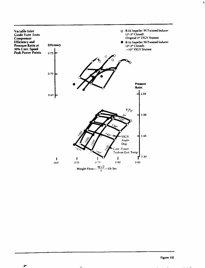
Val table InLt 0 8.52 Impeller W;Twisted Inducer Guide Y ~ n e Tests ( 2 " - 3 O Closed). C O ~ ~ T ~ S S O ~ Original 0" VICV Statoir Efficiency and B.52 Impeller WlTwistcd Inducer Pressure Ratio at Efficiency (2'-3" Closed); 50% Corr. Sped -10" VIGV Stators Peak Power Points 0.75
0.70
Rcuurr Ratio
.070 0 7 5 0 PO 0.95
w f i Weight Flow- - -Lb.'Sec
45
Figure 102
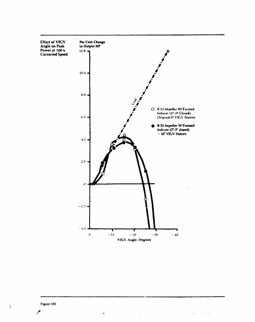
Effect of VlCV Anglc on Peak Power at 1006 Corrected Speed
Per Cent Change in Output HP
l Z O 1
0 8.52 Impeller WITwistd Inducer iZe-3. Closed): Oripnal On VIGV Stators
1' -- 10 - 211 -10 - 4 0
VlGV Anglc, Degrees
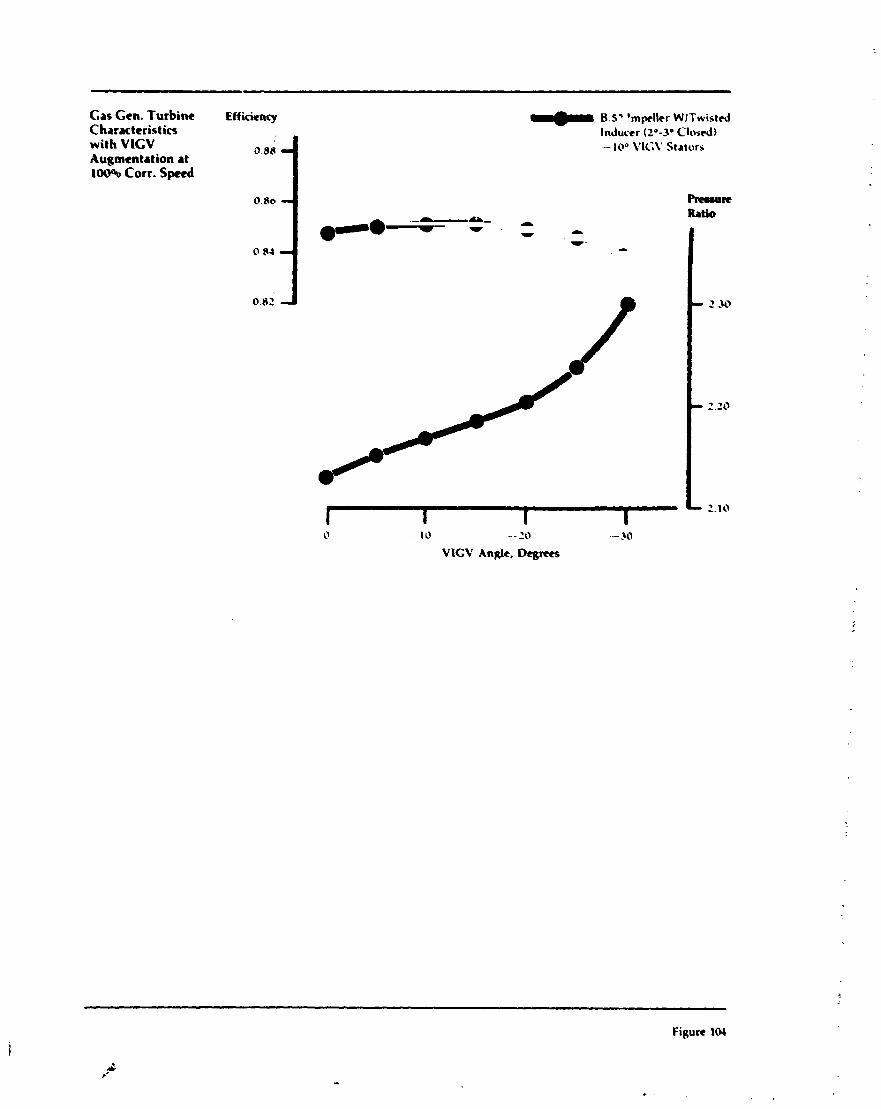
Gas Ccn. Turbine Efficiency B.5' 'mpllcr WITwistrJ Characteristics lnduccr (20-30 Closed) with VlCV 0.86 - 10" VICY Stators: Augmentation at 100% Corr. Speed
Rruum Y - A
Ratio - - - -~ - --
0 84 & -1 0.82 - 130
// w -.- - ' 0
/ t I I 1
- 2.10
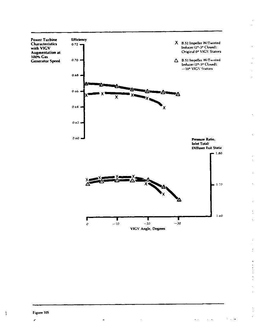
Power Turbine Efficiency Characteristics 0.72 X B.52 Impeller WITwisted with VlCV Inducer (20-30 Closed); Augmentation at Original 00 VICV Stators
100% Gas Generator Speed a 8.52 Impeller WfTwtsted
Inducer (2O-3O Closed); -lo0 VIGV Stators
0.68
(1 66 - x-x X
X
0.02
0.00 Rrssure Ratio, Inlet Totall Diffuser Exit Static
C -10 -20 - 30 VlGV Angle, Degms
Figure 105
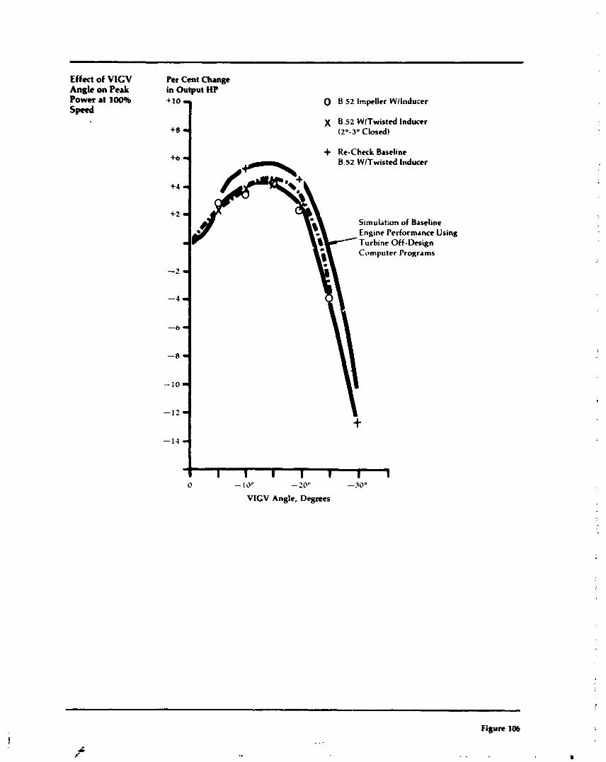
Effect of VlGV Angle on Peak Power at 10046 Spctd
Pet Cent Change in Output HP
0 B 52 Impeller Wllnducer
X B.52 WlTwisted Inducer (2'-3' CIo~cd)
1 + Re-Check Baseline B.52 WlTwistcd Inducer
Simulation of Baseline
, Computer programs
Using
0 - 10'- -2OC -30"
VlGV Angle, Degrees
Figure 106
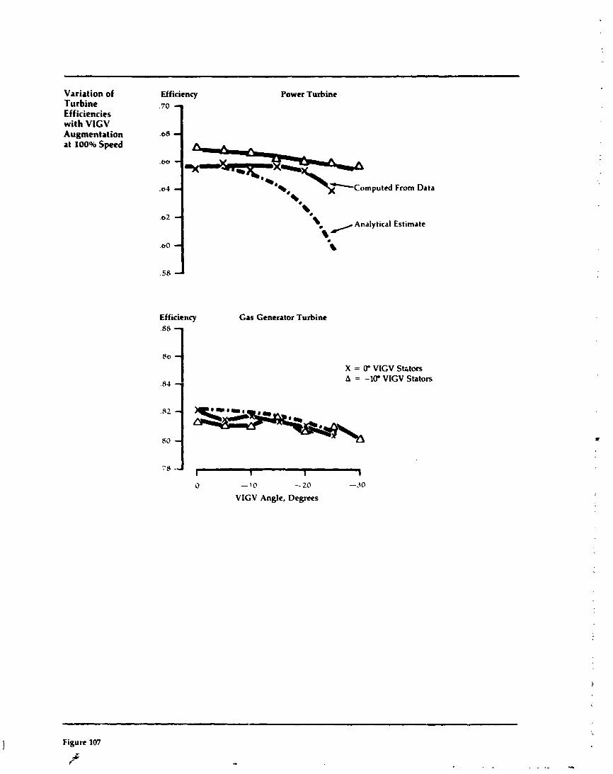
Variation of Efficiency Turbine Efficiencies with VlGV Augmentation " O .68 1
Power Turbine
at 100% Speed
From Data
Efficiency
-*\ Analytical Estimate i
Gas Generator Turbine
X = W VIGV Sktors A = -1W VIGV Stators
0 - 10 -20 -30
VIGV Angle, Degrees
Figure 107
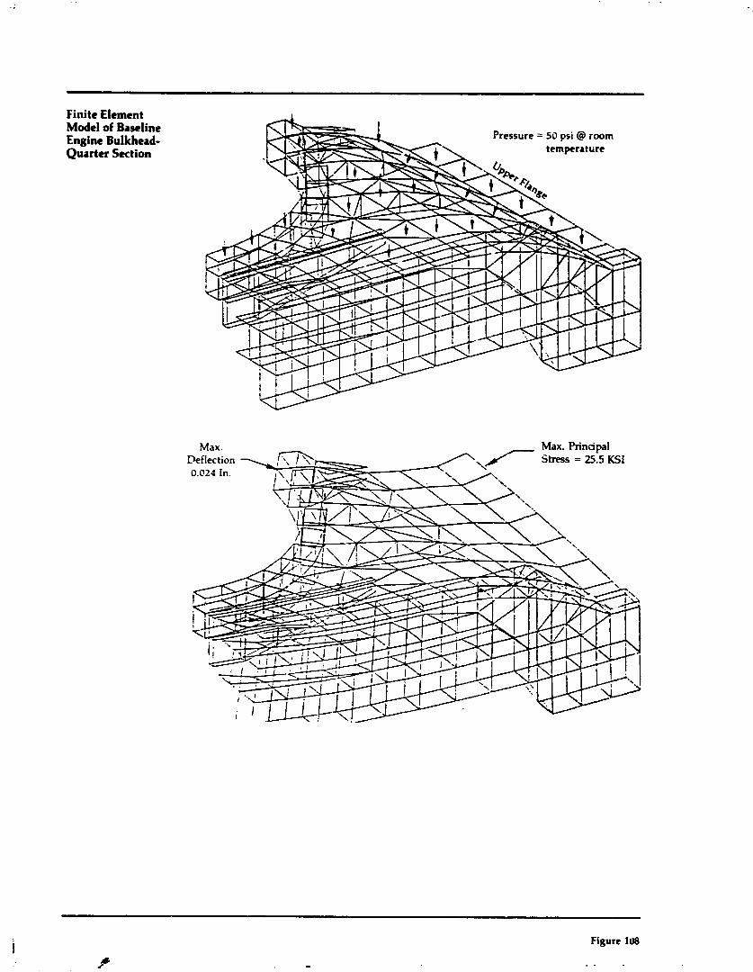
Finite Element Model af Baseline Engine Bulkhed- Quarter Section
Figure 1U8
. .

Summary of Baseline Engi~r Bulkhead Deflections
Deflectlor. - (In) Nastran
Guided
.0118 ,0170 ,0190
Figure 109
/":
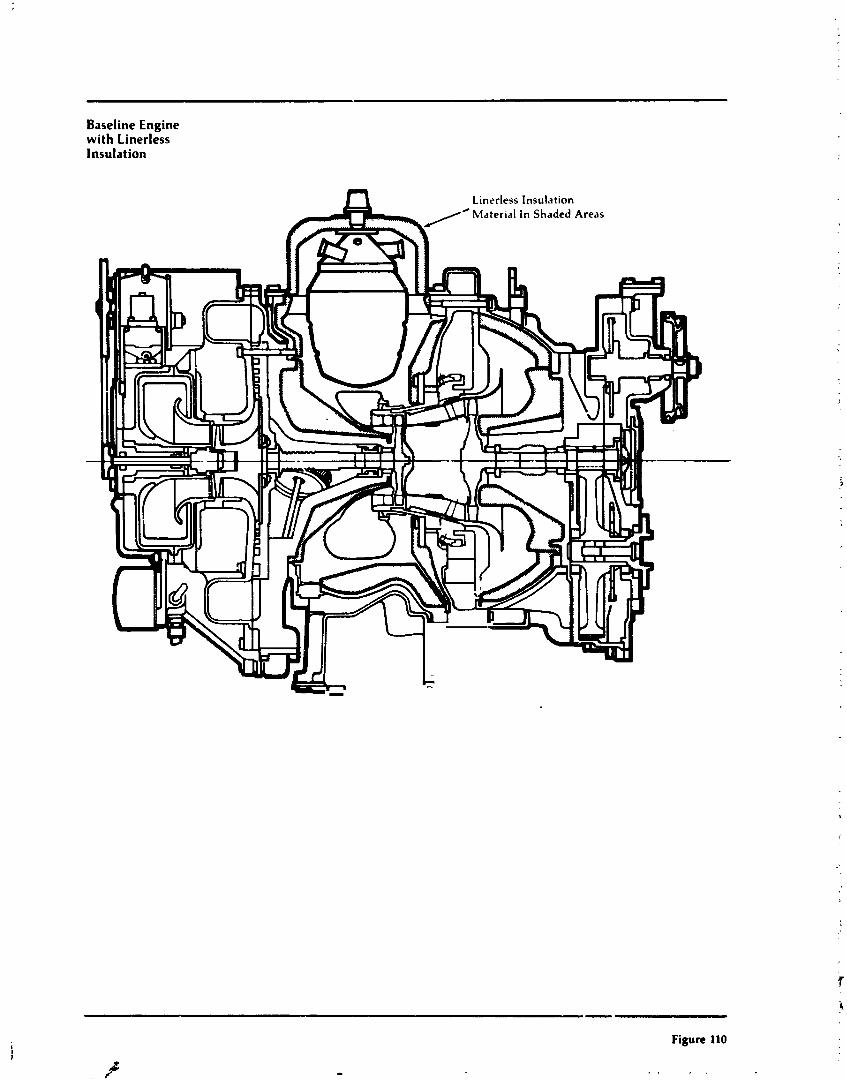
Baseline Engine with Linerless Insulation
- -- -- -- --
Figure 110
d F- . .
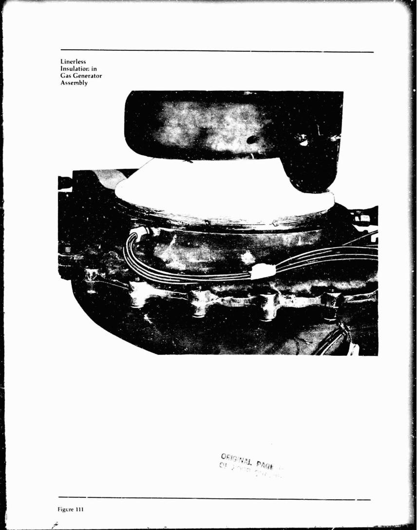
Linerless Insulatior. in Gas Generator Assembly

Linerloss Insulation in Power Turbine Assembly
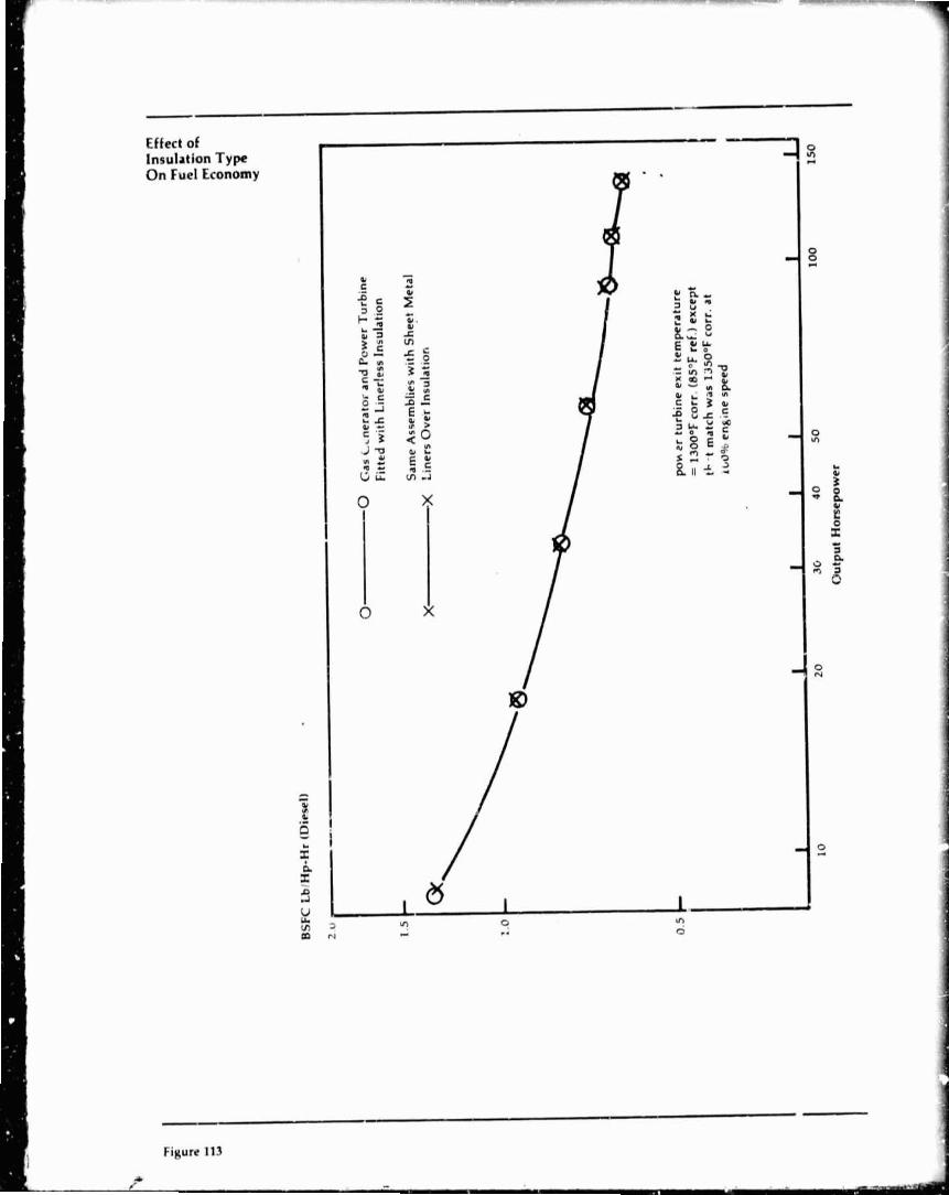
BSFC L
blH
p-H
I (D
iese
l)
0
0
Gas
L~
ner
ato
r and
Pcw
er T
urbi
ne
Fit
ted
wit
h L
iner
less
Ins
ulat
ion
1.5
S
ame
Ass
embl
ies
wit
h S
hee
t M
etal
x
X
Lin
ers
Ov
er
Insu
lati
on
0.5
p
ower
tur
bine
exi
t te
mpe
ratu
re
= 1
300°
F c
orr.
(8S°F ref.) e
xcep
t 1
th-t
mat
ch w
as 1
350°
F c
orr.
at
ibO%
engi
ne
spee
d
I I
I I
4 1
I 20
3G
4 0
50
10
0 10
Out
put
Hor
sep
ower
I
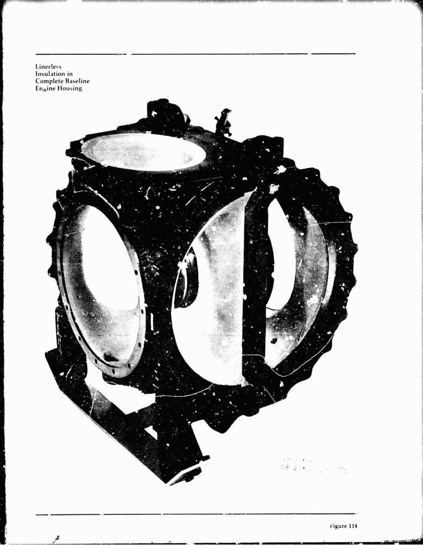
Linerlecs Insulation in Complete Baseline Ensine Housing
Related Documents