Balloon-borne hard X-ray polarimetry with PoGOLite Mark Pearce, Hans-Gustav Flor´ en, Miranda Jackson, Tune Kamae, M´ ozsi Kiss, Merlin Kole, Elena Moretti, G¨ oran Olofsson, Stefan Rydstr¨ om, Jan-Erik Str¨ omberg, Hiromitsu Takahashi (on behalf of The PoGOLite Collaboration) Abstract—PoGOLite is a hard X-ray polarimeter operating in the 25-100 keV energy band. The instrument design is optimised for the observation of compact astrophysical sources. Observa- tions are conducted from a stabilised stratospheric balloon plat- form at an altitude of approximately 40 km. The primary targets for first balloon flights of a reduced effective area instrument are the Crab and Cygnus-X1. The polarisation of incoming photons is determined using coincident Compton scattering and photo- absorption events reconstructed in an array of plastic scintillator detector cells surrounded by a bismuth germanate oxide (BGO) side anticoincidence shield and a polyethylene neutron shield. A custom attitude control system keeps the polarimeter field- of-view aligned to targets of interest, compensating for sidereal motion and perturbations such as torsional forces in the balloon rigging. An overview of the PoGOLite project is presented and the outcome of the ill-fated maiden balloon flight is discussed. Index Terms—polarisation, astrophysics, Compton, Crab, Cygnus X-1, scientific ballooning I. I NTRODUCTION I T is 50 years since Giaconni’s discovery of extrasolar X-rays. Geiger counters carried outside of the Earth’s atmosphere by an Aerobee sounding rocket registered X-rays from Scorpius-X1, now known to be an accreting neutron star. A significant and unexpected diffuse X-ray background was also observed. Since then, X-ray emissions from a plethora of objects have been recorded and our understanding of high- energy processes in the Universe has improved significantly. The resulting field of X-ray astrophysics has been driven by the development of new experimental techniques and, in particular, new methods for detecting X-rays. Giaconni’s Geiger counters were subsequently replaced by energy sensi- tive proportional counters which in turn have been replaced by semiconductor detectors such as charge coupled devices. Instruments are now-a-days flown on satellite missions giving Manuscript received November 15, 2012. This work was supported in part by The Knut and Alice Wallenberg Foundation, The Swedish National Space Board, The Swedish Research Council and the G¨ oran Gustafsson Foundation. M. Pearce is with KTH Royal Institute of Technology, Department of Physics, and the Oskar Klein Centre for Cosmoparticle Physics, AlbaNova University Centre, 10691 Stockholm, Sweden (e-mail: [email protected]). M. Jackson, M. Kiss, M. Kole, E. Moretti and S. Rydstr¨ om are with KTH Royal Institute of Technology, Department of Physics, and the Oskar Klein Centre for Cosmoparticle Physics, AlbaNova University Centre, 10691 Stockholm, Sweden. H.-G. Flor´ en and G. Olofsson are with Department of Astronomy, Stock- holm University AlbaNova University Centre, 10691 Stockholm, Sweden. J.-E. Str¨ omberg is with DST Control, Link¨ oping, Sweden. H. Takahashi is with Department of Physical Sciences, Hiroshima Univer- sity, Hiroshima, Japan. T. Kamae is with KiPAC, Stanford University, Menlo Park, USA. longer observing times for larger collecting areas. A common feature of essentially all missions to date is that they are designed to measure three aspects of the incident X-ray flux, namely the location of origin on the sky, the energy and the arrival time. The majority of instruments are not optimised for measurements of the polarisation of the incident flux. Polarised X-rays are expected from the high-energy pro- cesses at work within compact astrophysical objects such as pulsars, accreting black holes and jet-dominated active galaxies [1]. Polarisation is also expected to provide valuable information regarding the transient processes underlying so- lar flares [2] and gamma-ray bursts (GRB) [3]. Polarisation arises naturally for synchrotron radiation in large-scale ordered magnetic fields and for photons propagating through a strong magnetic field. Polarisation can also result from anisotropic Compton scattering. In all cases, the orientation (’angle’) of the polarisation plane and degree of polarisation are a powerful probe of the physical environment around compact astrophysical sources. The diagnostic worth of polarisation is exemplified for the case of pulsars. Although discovered in 1967, there is still no generally accepted model to explain the high energy emission. In figure 1, three competing models for high energy emission from the Crab pulsar are shown. In the polar cap model 1 , electrons (positrons) are accelerated in open field line regions at the polar cap regions of the neutron star. The accelerated particles and associated electromagnetic cascades emit synchrotron and curvature radiation while in the vicinity of the non-uniform magnetic field in the polar region. In the caustic model, particle acceleration and emission occur along the edge of the open field region - extending from the surface of the neutron star to the light cylinder. In the outer gap model, electrons are accelerated in the vacuum gaps between the open and closed magnetic field lines in the outer magnetosphere. As shown in the upper panels of the figure, the predicted light- curves for the three emission models are similar - especially when instrument response is included. The polarisation degree (lower panels) and angle (middle panels) show very different signatures for the three models. Despite the wealth of sources accessible to polarisation measurements and the importance of these measurements, there has been only one successful mission with dedicated instrumentation optimised for compact sources. The Crab 1 It is noted that this model is disfavoured by precision measurements of the Crab emission spectrum by the Fermi Gamma-ray Space Telescope [4]. arXiv:1211.5094v2 [astro-ph.IM] 8 Mar 2013

Welcome message from author
This document is posted to help you gain knowledge. Please leave a comment to let me know what you think about it! Share it to your friends and learn new things together.
Transcript

Balloon-borne hard X-ray polarimetry withPoGOLite
Mark Pearce, Hans-Gustav Floren, Miranda Jackson, Tune Kamae, Mozsi Kiss, Merlin Kole, Elena Moretti,Goran Olofsson, Stefan Rydstrom, Jan-Erik Stromberg, Hiromitsu Takahashi (on behalf of The PoGOLite
Collaboration)
Abstract—PoGOLite is a hard X-ray polarimeter operating inthe 25-100 keV energy band. The instrument design is optimisedfor the observation of compact astrophysical sources. Observa-tions are conducted from a stabilised stratospheric balloon plat-form at an altitude of approximately 40 km. The primary targetsfor first balloon flights of a reduced effective area instrument arethe Crab and Cygnus-X1. The polarisation of incoming photonsis determined using coincident Compton scattering and photo-absorption events reconstructed in an array of plastic scintillatordetector cells surrounded by a bismuth germanate oxide (BGO)side anticoincidence shield and a polyethylene neutron shield.A custom attitude control system keeps the polarimeter field-of-view aligned to targets of interest, compensating for siderealmotion and perturbations such as torsional forces in the balloonrigging. An overview of the PoGOLite project is presented andthe outcome of the ill-fated maiden balloon flight is discussed.
Index Terms—polarisation, astrophysics, Compton, Crab,Cygnus X-1, scientific ballooning
I. INTRODUCTION
IT is 50 years since Giaconni’s discovery of extrasolarX-rays. Geiger counters carried outside of the Earth’s
atmosphere by an Aerobee sounding rocket registered X-raysfrom Scorpius-X1, now known to be an accreting neutron star.A significant and unexpected diffuse X-ray background wasalso observed. Since then, X-ray emissions from a plethoraof objects have been recorded and our understanding of high-energy processes in the Universe has improved significantly.The resulting field of X-ray astrophysics has been drivenby the development of new experimental techniques and,in particular, new methods for detecting X-rays. Giaconni’sGeiger counters were subsequently replaced by energy sensi-tive proportional counters which in turn have been replacedby semiconductor detectors such as charge coupled devices.Instruments are now-a-days flown on satellite missions giving
Manuscript received November 15, 2012. This work was supported in partby The Knut and Alice Wallenberg Foundation, The Swedish National SpaceBoard, The Swedish Research Council and the Goran Gustafsson Foundation.
M. Pearce is with KTH Royal Institute of Technology, Department ofPhysics, and the Oskar Klein Centre for Cosmoparticle Physics, AlbaNovaUniversity Centre, 10691 Stockholm, Sweden (e-mail: [email protected]).
M. Jackson, M. Kiss, M. Kole, E. Moretti and S. Rydstrom are withKTH Royal Institute of Technology, Department of Physics, and the OskarKlein Centre for Cosmoparticle Physics, AlbaNova University Centre, 10691Stockholm, Sweden.
H.-G. Floren and G. Olofsson are with Department of Astronomy, Stock-holm University AlbaNova University Centre, 10691 Stockholm, Sweden.
J.-E. Stromberg is with DST Control, Linkoping, Sweden.H. Takahashi is with Department of Physical Sciences, Hiroshima Univer-
sity, Hiroshima, Japan.T. Kamae is with KiPAC, Stanford University, Menlo Park, USA.
longer observing times for larger collecting areas. A commonfeature of essentially all missions to date is that they aredesigned to measure three aspects of the incident X-ray flux,namely the location of origin on the sky, the energy and thearrival time. The majority of instruments are not optimised formeasurements of the polarisation of the incident flux.
Polarised X-rays are expected from the high-energy pro-cesses at work within compact astrophysical objects suchas pulsars, accreting black holes and jet-dominated activegalaxies [1]. Polarisation is also expected to provide valuableinformation regarding the transient processes underlying so-lar flares [2] and gamma-ray bursts (GRB) [3]. Polarisationarises naturally for synchrotron radiation in large-scale orderedmagnetic fields and for photons propagating through a strongmagnetic field. Polarisation can also result from anisotropicCompton scattering. In all cases, the orientation (’angle’)of the polarisation plane and degree of polarisation are apowerful probe of the physical environment around compactastrophysical sources.
The diagnostic worth of polarisation is exemplified forthe case of pulsars. Although discovered in 1967, there isstill no generally accepted model to explain the high energyemission. In figure 1, three competing models for high energyemission from the Crab pulsar are shown. In the polar capmodel1, electrons (positrons) are accelerated in open fieldline regions at the polar cap regions of the neutron star. Theaccelerated particles and associated electromagnetic cascadesemit synchrotron and curvature radiation while in the vicinityof the non-uniform magnetic field in the polar region. In thecaustic model, particle acceleration and emission occur alongthe edge of the open field region - extending from the surfaceof the neutron star to the light cylinder. In the outer gap model,electrons are accelerated in the vacuum gaps between the openand closed magnetic field lines in the outer magnetosphere. Asshown in the upper panels of the figure, the predicted light-curves for the three emission models are similar - especiallywhen instrument response is included. The polarisation degree(lower panels) and angle (middle panels) show very differentsignatures for the three models.
Despite the wealth of sources accessible to polarisationmeasurements and the importance of these measurements,there has been only one successful mission with dedicatedinstrumentation optimised for compact sources. The Crab
1It is noted that this model is disfavoured by precision measurements ofthe Crab emission spectrum by the Fermi Gamma-ray Space Telescope [4].
arX
iv:1
211.
5094
v2 [
astr
o-ph
.IM
] 8
Mar
201
3
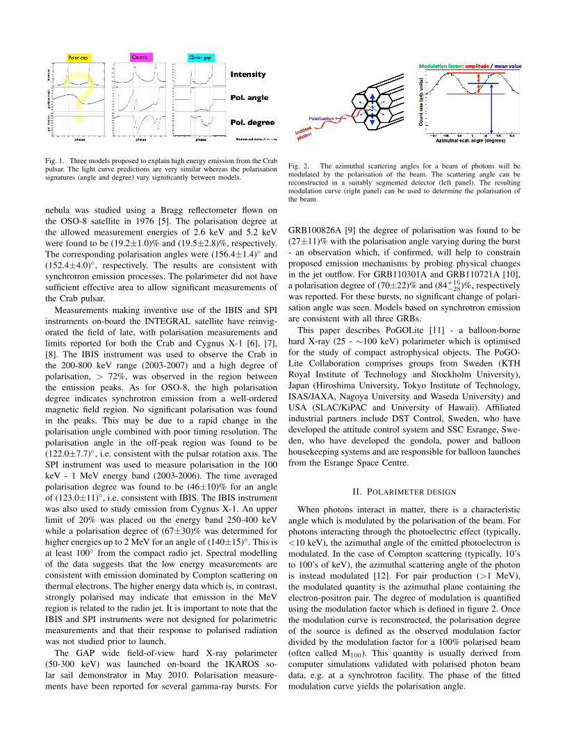
Fig. 1. Three models proposed to explain high energy emission from the Crabpulsar. The light curve predictions are very similar whereas the polarisationsignatures (angle and degree) vary significantly between models.
nebula was studied using a Bragg reflectometer flown onthe OSO-8 satellite in 1976 [5]. The polarisation degree atthe allowed measurement energies of 2.6 keV and 5.2 keVwere found to be (19.2±1.0)% and (19.5±2.8)%, respectively.The corresponding polarisation angles were (156.4±1.4)◦ and(152.4±4.0)◦, respectively. The results are consistent withsynchrotron emission processes. The polarimeter did not havesufficient effective area to allow significant measurements ofthe Crab pulsar.
Measurements making inventive use of the IBIS and SPIinstruments on-board the INTEGRAL satellite have reinvig-orated the field of late, with polarisation measurements andlimits reported for both the Crab and Cygnus X-1 [6], [7],[8]. The IBIS instrument was used to observe the Crab inthe 200-800 keV range (2003-2007) and a high degree ofpolarisation, > 72%, was observed in the region betweenthe emission peaks. As for OSO-8, the high polarisationdegree indicates synchrotron emission from a well-orderedmagnetic field region. No significant polarisation was foundin the peaks. This may be due to a rapid change in thepolarisation angle combined with poor timing resolution. Thepolarisation angle in the off-peak region was found to be(122.0±7.7)◦, i.e. consistent with the pulsar rotation axis. TheSPI instrument was used to measure polarisation in the 100keV - 1 MeV energy band (2003-2006). The time averagedpolarisation degree was found to be (46±10)% for an angleof (123.0±11)◦, i.e. consistent with IBIS. The IBIS instrumentwas also used to study emission from Cygnus X-1. An upperlimit of 20% was placed on the energy band 250-400 keVwhile a polarisation degree of (67±30)% was determined forhigher energies up to 2 MeV for an angle of (140±15)◦. This isat least 100◦ from the compact radio jet. Spectral modellingof the data suggests that the low energy measurements areconsistent with emission dominated by Compton scattering onthermal electrons. The higher energy data which is, in contrast,strongly polarised may indicate that emission in the MeVregion is related to the radio jet. It is important to note that theIBIS and SPI instruments were not designed for polarimetricmeasurements and that their response to polarised radiationwas not studied prior to launch.
The GAP wide field-of-view hard X-ray polarimeter(50-300 keV) was launched on-board the IKAROS so-lar sail demonstrator in May 2010. Polarisation measure-ments have been reported for several gamma-ray bursts. For
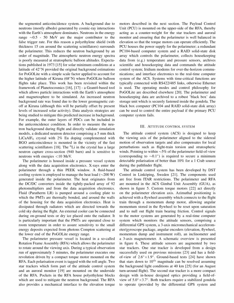
Fig. 2. The azimuthal scattering angles for a beam of photons will bemodulated by the polarisation of the beam. The scattering angle can bereconstructed in a suitably segmented detector (left panel). The resultingmodulation curve (right panel) can be used to determine the polarisation ofthe beam.
GRB100826A [9] the degree of polarisation was found to be(27±11)% with the polarisation angle varying during the burst- an observation which, if confirmed, will help to constrainproposed emission mechanisms by probing physical changesin the jet outflow. For GRB110301A and GRB110721A [10],a polarisation degree of (70±22)% and (84+16
−28)%, respectivelywas reported. For these bursts, no significant change of polari-sation angle was seen. Models based on synchrotron emissionare consistent with all three GRBs.
This paper describes PoGOLite [11] - a balloon-bornehard X-ray (25 - ∼100 keV) polarimeter which is optimisedfor the study of compact astrophysical objects. The PoGO-Lite Collaboration comprises groups from Sweden (KTHRoyal Institute of Technology and Stockholm University),Japan (Hiroshima University, Tokyo Institute of Technology,ISAS/JAXA, Nagoya University and Waseda University) andUSA (SLAC/KiPAC and University of Hawaii). Affiliatedindustrial partners include DST Control, Sweden, who havedeveloped the attitude control system and SSC Esrange, Swe-den, who have developed the gondola, power and balloonhousekeeping systems and are responsible for balloon launchesfrom the Esrange Space Centre.
II. POLARIMETER DESIGN
When photons interact in matter, there is a characteristicangle which is modulated by the polarisation of the beam. Forphotons interacting through the photoelectric effect (typically,<10 keV), the azimuthal angle of the emitted photoelectron ismodulated. In the case of Compton scattering (typically, 10’sto 100’s of keV), the azimuthal scattering angle of the photonis instead modulated [12]. For pair production (>1 MeV),the modulated quantity is the azimuthal plane containing theelectron-positron pair. The degree of modulation is quantifiedusing the modulation factor which is defined in figure 2. Oncethe modulation curve is reconstructed, the polarisation degreeof the source is defined as the observed modulation factordivided by the modulation factor for a 100% polarised beam(often called M100). This quantity is usually derived fromcomputer simulations validated with polarised photon beamdata, e.g. at a synchrotron facility. The phase of the fittedmodulation curve yields the polarisation angle.

Fig. 3. Left: an overview of the PoGOLite polarimeter design showing thescintillator components. Right: a schematic cross section of the PoGOLiteinstrument (not to scale) showing valid and background photon interactions.Possible background atmospheric neutron interactions are also shown. EachPDC is ∼1 m long. The side anticoincidence shield (SAS) is segmented toallow background asymmetries to be studied in flight.
In the case of PoGOLite, polarisation is determined bystudying the distribution of azimuthal Compton scatteringangles in a segmented detector comprising plastic scintillatorswhich due to their low atomic number provide a favourablecross-section for Compton scattering while also maintainingacceptable sensitivity for photoelectric absorption. Given theconstraints of a balloon-borne mission, a plastic-based instru-ment also allows for a large effective area while maintaininga reasonable M100. Polarisation events are characterised bya Compton scatter and a photoelectric absorption in nearbydetector elements. The Compton scattering and photoabsorp-tion events are identified in an array of phoswich detectorcells (PDC) made of plastic and BGO scintillators, surroundedby a segmented BGO side anticoincidence shield (SAS), asshown in figure 3. The full-size PoGOLite instrument consistsof 217 PDC units. For the maiden ’pathfinder’ flight, a reducedvolume instrument will be flown consisting of 61 PDC units.Each PDC is composed of a thin-walled tube (well) of slowplastic scintillator at the top (fluorescence decay time ∼280 ns,length 60 cm), a solid rod of fast plastic scintillator (decay time∼2 ns, length 20 cm), and a BGO crystal at the bottom (decaytime ∼300 ns, length 4 cm), all viewed by one photomultipliertube (PMT) - Hamamatsu R7899EGKNP. The wells serve asa charged particle anticoincidence, the fast scintillator rodsas photon detectors, and the bottom BGOs act as a loweranticoincidence. Each well is sheathed in thin layers of tinand lead foils to provide passive collimation.
Figure 3 shows a simplified cross-section of the polarimeterwith possible photon interactions indicated. X-rays enteringwithin the field-of-view of the instrument (∼2◦×2◦ (FWHM),defined by the slow plastic collimators) will hit one of thefast plastic scintillators and may be Compton scattered, with aprobability that depends on the photon energy. The scatteredphoton may escape, be photoabsorbed in another detector, orundergo a second scattering. Electrons resulting from a pho-toabsorption will deposit their energy in the plastic scintillatorand produce a signal at the PMT. A 25 keV Compton scatteringevent will result in a 1-3 keV energy deposit in the fast plasticscintillator, requiring single photoelectron detection. The PMT
Fig. 4. The scintillator components of the phoswich detector cells (PDCs)and side anticoincidence system.
is designed to have ∼0.05 photoelectron ripple for a gainof 106. The detection of an energy deposit compatible withphotoabsorption initiates high speed waveform sampling ofPMT outputs from all PDCs with signals above a threshold.Valid Compton scattering events will be selected from thesewaveforms after the completion of a flight. A SpaceWire-baseddata acquisition system performs the waveform digitisationusing 12 bit flash ADCs operating at 37.5 MHz [13]. In theabsence of veto signals, e.g. from pulse shape discrimination(indicating slow scintillator or anticoincidence activity) orcorresponding to the large energy deposits from an interactingcharged cosmic-ray, PDC waveforms are saved with 15 pre-and 35 post-trigger samples. The locations of the PDCs inwhich the Compton scatter and photoabsorption are detecteddetermine the azimuthal Compton scattering angle. The ge-ometry of the PDC arrangement limits the polar scatteringangle to approximately (90±30)◦, roughly orthogonal to theincident direction. Little of the energy of an incident gamma-ray photon is lost at the Compton scattering site(s). Most ofthe energy is deposited at the photoabsorption site. This makesit straight-forward to differentiate Compton scattering sitesfrom photoabsorption sites despite the relatively poor energyresolution of plastic scintillator. Each polarisation event can betime-tagged with a precision of ∼1µs using a local precisionoscillator synchronised to GPS pulse-per-second informationfrom the attitude control system.
The performance of the polarimeter is discussed in detailelsewhere [11], [14]. At 50 keV the effective area is 200 cm2
(40 cm2 for the pathfinder) for a M100 of ∼30%. The minimumdetectable polarisation is expected to be ∼10% for a 200mCrab (1 Crab for the pathfinder) Crab-like source duringa single ballooning campaign. Background contributions to aCrab observation by the PoGOLite pathfinder simulated usingGeant4 indicate that the minimum ionising particle signaturein scintillators arising from charged cosmic-ray backgroundsis readily reduced using a simple pulse height analysis. Thephoton background arises from both atmospheric and galacticsources. This background is suppressed due to the narrowfield-of-view provided by the PDC design combined with
the segmented anticoincidence system. A background due toneutrons (mostly albedo) generated by cosmic-ray interactionswith the Earth’s atmosphere dominates. Neutrons in the energyrange ∼0.5 - 50 MeV are the major contributor to thefalse trigger rate. For this reason a polyethylene shield (withthickness 15 cm around the scattering scintillators) surroundsthe polarimeter. This reduces the neutron background by anorder of magnitude. The atmospheric neutron energy spectrais poorly measured at stratospheric balloon altitudes. Expecta-tions published in 1973 [15] for solar minimum conditions at alatitude of 42◦N provided the original background estimationsfor PoGOLite with a simple scale factor applied to account forthe higher latitude of Kiruna (68◦N) where PoGOLite balloonflights take place. This work has been revisited within theframework of Planetocosmics [16], [17] - a Geant4-based toolwhich allows particle interactions with the Earth’s atmosphereand magnetosphere to be simulated. An increased neutronbackground rate was found due to the lower geomagnetic cut-off at Kiruna (although this will be partially offset by presentlevels of increased solar activity). Data analysis strategies arebeing studied to mitigate this predicted increase in background.For example, the outer layers of PDCs can be included inthe anticoincidence condition. In order to measure the neu-tron background during flight and directly validate simulationmodels, a dedicated neutron detector comprising a 5 mm thickLiCaAlF6 crystal with 2% Eu doping complemented withBGO anticoincidence is mounted in the vicinity of the fastscattering scintillators [18]. The 6Li in the crystal has a largeneutron capture cross-section (940 barn) and is sensitive toneutrons with energies <10 MeV.
The polarimeter is housed inside a pressure vessel systemalong with the data acquisition electronics. X-rays enter thepolarimeter through a thin PEEK window. A fluid-basedcooling system is employed to manage the heat load (∼200 W)generated inside the polarimeter. The heat originates fromthe DC/DC converters inside the tightly-packed array of 92photomultipliers and from the data acquisition electronics.Fluid (Paratherm LR) is pumped around a cooling plate towhich the PMTs are thermally bonded, and around the wallsof the housing for the data acquisition electronics. Heat isdissipated through radiators which are directed towards thecold sky during the flight. An external cooler can be connectedduring on-ground tests or dry ice placed onto the radiator. Itis particularly important that the PMTs are operated close toroom temperature in order to assure sensitivity to the smallenergy deposits expected from photons Compton scattering atthe lower end of the PoGOLite energy range.
The polarimeter pressure vessel is located in a so-calledRotation Frame Assembly (RFA) which allows the polarimeterto rotate around the viewing axis. During a typical observationrun of approximately 5 minutes, the polarimeter executes onerevolution driven by a compact torque motor mounted on theRFA. Each polarisation event is tagged with the roll angle. Twostar trackers which form part of the attitude control systemand an auroral monitor [19] are mounted on the undersideof the RFA. Pockets in the RFA house polyethylene blockswhich are used to mitigate the neutron background. The RFAalso provides a mechanical interface to the elevation torque
motors described in the next section. The Payload ControlUnit (PCU) is mounted on the upper-side of the RFA, therebyacting as a counter-weight for the star trackers and auroralmonitor and ensuring that the polarimeter is well balanced inelevation so that the torque motors can operate efficiently. ThePCU houses the power supply for the polarimeter; a redundantPC104-based computer system and a RAID solid-state diskarray which controls the polarimeter, collects housekeepingdata from (e.g.) temperature and pressure sensors, archivesscientific and housekeeping data and commands the attitudecontrol system; Iridium modems for over-the-horizon commu-nications; and interface electronics to the real-time computersystem of the ACS. Systems with time-critical functions aretypically connected with RS422/485 links, otherwise Ethernetis used. The operating modes and control philosophy forPoGOLite are described elsewhere [20]. The polarimeter andhousekeeping data are archived to a robust ’black box’ datastorage unit which is securely fastened inside the gondola. Theblack box computer (PC104 and RAID solid-state disk array)can be used to control the entire payload if the primary PCUcomputer system fails.
III. ATTITUDE CONTROL SYSTEM
The attitude control system (ACS) is designed to keepthe viewing axis of the polarimeter aligned to the siderealmotion of observation targets and also compensates for localperturbations such as flight-train torsion and stratosphericwinds. Pointing to within ∼5% of the polarimeter field-of-view(corresponding to ∼0.1◦) is required to secure a minimumdetectable polarisation of better than 10% for a 1 Crab sourceduring the pathfinder flight.
The attitude control system has been developed by DSTControl in Linkoping, Sweden [21]. The components usedare free from ITAR restrictions. The polarimeter and RFAare mounted in the ACS Gimbal Unit Assembly (GUA), asshown in figure 5. Custom torque motors [22] act directlyon the polarimeter elevation axis. Azimuthal positioning isachieved with a flywheel assembly which connects to the flighttrain through a momentum dump motor, allowing angularmomentum stored in the flywheel to be reset upon saturationand to null out flight train bearing friction. Control signalsto the motor systems are generated by a real-time computersystem which monitors the attitude sensors, comprising adifferential GPS system, a 3-axis micromechanical accelerom-eter/gyroscope package, angular encoders (elevation, flywheel,momentum dump and instrument roll), an inclinometer anda 3-axis magnetometer. A schematic overview is presentedin figure 6. These attitude sensors are augmented by twostar trackers. One star tracker is developed from a designsuccessfully used on previous missions [23] and has a field-of-view of 2.6◦×1.9◦. Ground-based tests [24] have shownthat stars down to 10th magnitude can be resolved assumingthe background light conditions at 40 km [25] (for an Augustturn-around flight). The second star tracker is a more compactdesign with in-house designed optics providing a field-of-view of 5.0◦×3.7◦. Both trackers require a stabilized gondolato operate (provided by the differential GPS system and

Fig. 5. The PoGOLite attitude control system. The polarimeter is mounted inthe Gimbal Unit Assembly (GUA) where custom direct drive torque motorsact on the polarimeter elevation axle of the Rotation Frame Assembly (RFA).The polarimeter can roll around the viewing axis within the RFA. The balloonflight train connects to the gimbal assembly through a combined momentumdump/flywheel system which is used for azimuthal positioning. The PayloadControl Unit (PCU) and auroral monitor are not shown.
gyroscopes) and can either operate in a star pattern matchingmode (providing relatively slow, but absolute position fixes) orcan be commanded to lock onto a bright star providing ACSupdates at a rate of 10-100 Hz. The latter case is foreseen tobe the primary operating mode during flight.
IV. COMMUNICATIONS
When in line-of-sight (LOS) from Esrange, communica-tions with the gondola use the E-Link system developedby SSC [26]. This is an implementation of 10/100 Base-TEthernet over a S-band radio system which supports duplextraffic at up to 2 Mb/s. The maximum LOS range is approx-imately 500 km for a balloon at float altitude. Atmosphericconditions may have a significant impact on the link range.An updated version of E-Link with a data capacity exceeding20 Mb/s (with lower mass and power consumption) is underdevelopment and will be flown on future PoGOLite flights.Once the gondola drops below the horizon, the Iridium satellitecommunications system is used. Two (for redundancy) dial-up data links are used to monitor and potentially control theACS and two RUDICS (Router-based Unrestricted Digital
Fig. 6. A simplified block diagram of the PoGOLite attitude control system.
Internetworking Connectivity Solutions) links are used tomonitor and command the entire payload. The dial-up linksoperate in a point-to-point mode, with Iridium modems andantenna on the ground used to dial-up to modems on-balloon(via the Iridium satellite constellation). For the RUDICSlinks, modems on-balloon communicate directly with Iridium’scommercial ground-stations (again, via the Iridium satelliteconstellation) where the call is terminated at a user specifiedIP address. For PoGOLite, this corresponds to a redundantserver system located in Stockholm. This system has theadvantage that TCP/IP packets can be sent directly over thelink. On-balloon, the dial-up and RUDICS links are cross-connected to provide an additional layer of redundancy incase of link failure. The data rate is far inferior to E-Linkat approximately 1 kb/s per link. Reliable on-board datastorage and space efficient housekeeping data is therefore vital.During the Iridium phase of the flight, the gondola is foreseento operate autonomously through a predefined observationschedule. There are additional Iridium links (dial-up and SBD- ’short burst data’) for Esrange housekeeping and commandfunctions.
V. GONDOLA AND ANCILLARY SYSTEMS
As shown in figure 7, the polarimeter and ACS are installedin a gondola assembly (designed by SSC Esrange). Theupper part of the gondola is connected to the Gimbal UnitAssembly and also provides a mounting point for the cooling
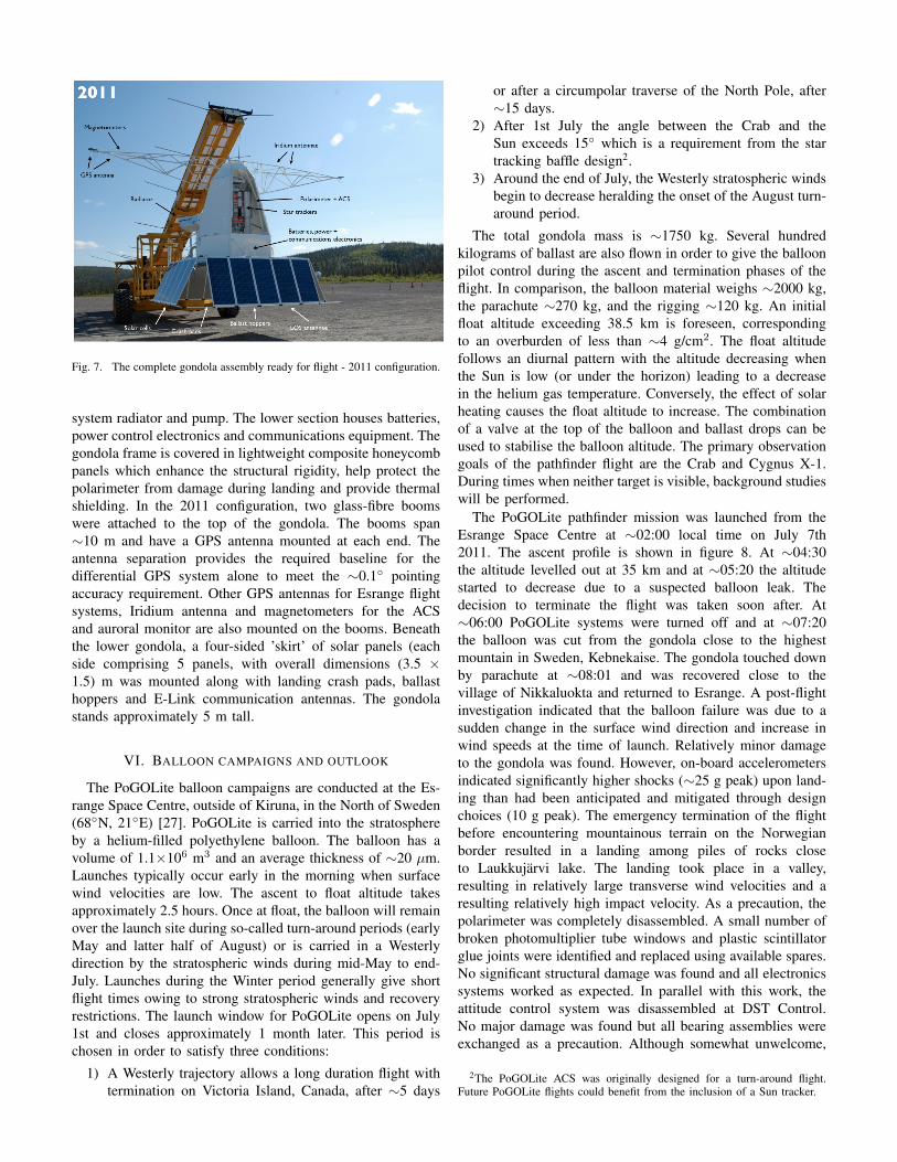
Fig. 7. The complete gondola assembly ready for flight - 2011 configuration.
system radiator and pump. The lower section houses batteries,power control electronics and communications equipment. Thegondola frame is covered in lightweight composite honeycombpanels which enhance the structural rigidity, help protect thepolarimeter from damage during landing and provide thermalshielding. In the 2011 configuration, two glass-fibre boomswere attached to the top of the gondola. The booms span∼10 m and have a GPS antenna mounted at each end. Theantenna separation provides the required baseline for thedifferential GPS system alone to meet the ∼0.1◦ pointingaccuracy requirement. Other GPS antennas for Esrange flightsystems, Iridium antenna and magnetometers for the ACSand auroral monitor are also mounted on the booms. Beneaththe lower gondola, a four-sided ’skirt’ of solar panels (eachside comprising 5 panels, with overall dimensions (3.5 ×1.5) m was mounted along with landing crash pads, ballasthoppers and E-Link communication antennas. The gondolastands approximately 5 m tall.
VI. BALLOON CAMPAIGNS AND OUTLOOK
The PoGOLite balloon campaigns are conducted at the Es-range Space Centre, outside of Kiruna, in the North of Sweden(68◦N, 21◦E) [27]. PoGOLite is carried into the stratosphereby a helium-filled polyethylene balloon. The balloon has avolume of 1.1×10⁶ m3 and an average thickness of ∼20 µm.Launches typically occur early in the morning when surfacewind velocities are low. The ascent to float altitude takesapproximately 2.5 hours. Once at float, the balloon will remainover the launch site during so-called turn-around periods (earlyMay and latter half of August) or is carried in a Westerlydirection by the stratospheric winds during mid-May to end-July. Launches during the Winter period generally give shortflight times owing to strong stratospheric winds and recoveryrestrictions. The launch window for PoGOLite opens on July1st and closes approximately 1 month later. This period ischosen in order to satisfy three conditions:
1) A Westerly trajectory allows a long duration flight withtermination on Victoria Island, Canada, after ∼5 days
or after a circumpolar traverse of the North Pole, after∼15 days.
2) After 1st July the angle between the Crab and theSun exceeds 15◦ which is a requirement from the startracking baffle design2.
3) Around the end of July, the Westerly stratospheric windsbegin to decrease heralding the onset of the August turn-around period.
The total gondola mass is ∼1750 kg. Several hundredkilograms of ballast are also flown in order to give the balloonpilot control during the ascent and termination phases of theflight. In comparison, the balloon material weighs ∼2000 kg,the parachute ∼270 kg, and the rigging ∼120 kg. An initialfloat altitude exceeding 38.5 km is foreseen, correspondingto an overburden of less than ∼4 g/cm2. The float altitudefollows an diurnal pattern with the altitude decreasing whenthe Sun is low (or under the horizon) leading to a decreasein the helium gas temperature. Conversely, the effect of solarheating causes the float altitude to increase. The combinationof a valve at the top of the balloon and ballast drops can beused to stabilise the balloon altitude. The primary observationgoals of the pathfinder flight are the Crab and Cygnus X-1.During times when neither target is visible, background studieswill be performed.
The PoGOLite pathfinder mission was launched from theEsrange Space Centre at ∼02:00 local time on July 7th2011. The ascent profile is shown in figure 8. At ∼04:30the altitude levelled out at 35 km and at ∼05:20 the altitudestarted to decrease due to a suspected balloon leak. Thedecision to terminate the flight was taken soon after. At∼06:00 PoGOLite systems were turned off and at ∼07:20the balloon was cut from the gondola close to the highestmountain in Sweden, Kebnekaise. The gondola touched downby parachute at ∼08:01 and was recovered close to thevillage of Nikkaluokta and returned to Esrange. A post-flightinvestigation indicated that the balloon failure was due to asudden change in the surface wind direction and increase inwind speeds at the time of launch. Relatively minor damageto the gondola was found. However, on-board accelerometersindicated significantly higher shocks (∼25 g peak) upon land-ing than had been anticipated and mitigated through designchoices (10 g peak). The emergency termination of the flightbefore encountering mountainous terrain on the Norwegianborder resulted in a landing among piles of rocks closeto Laukkujarvi lake. The landing took place in a valley,resulting in relatively large transverse wind velocities and aresulting relatively high impact velocity. As a precaution, thepolarimeter was completely disassembled. A small number ofbroken photomultiplier tube windows and plastic scintillatorglue joints were identified and replaced using available spares.No significant structural damage was found and all electronicssystems worked as expected. In parallel with this work, theattitude control system was disassembled at DST Control.No major damage was found but all bearing assemblies wereexchanged as a precaution. Although somewhat unwelcome,
2The PoGOLite ACS was originally designed for a turn-around flight.Future PoGOLite flights could benefit from the inclusion of a Sun tracker.
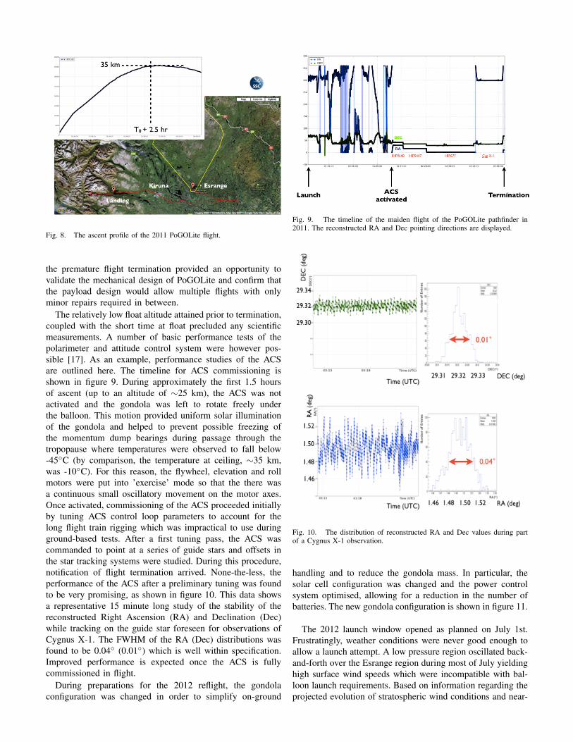
Fig. 8. The ascent profile of the 2011 PoGOLite flight.
the premature flight termination provided an opportunity tovalidate the mechanical design of PoGOLite and confirm thatthe payload design would allow multiple flights with onlyminor repairs required in between.
The relatively low float altitude attained prior to termination,coupled with the short time at float precluded any scientificmeasurements. A number of basic performance tests of thepolarimeter and attitude control system were however pos-sible [17]. As an example, performance studies of the ACSare outlined here. The timeline for ACS commissioning isshown in figure 9. During approximately the first 1.5 hoursof ascent (up to an altitude of ∼25 km), the ACS was notactivated and the gondola was left to rotate freely underthe balloon. This motion provided uniform solar illuminationof the gondola and helped to prevent possible freezing ofthe momentum dump bearings during passage through thetropopause where temperatures were observed to fall below-45◦C (by comparison, the temperature at ceiling, ∼35 km,was -10◦C). For this reason, the flywheel, elevation and rollmotors were put into ’exercise’ mode so that the there wasa continuous small oscillatory movement on the motor axes.Once activated, commissioning of the ACS proceeded initiallyby tuning ACS control loop parameters to account for thelong flight train rigging which was impractical to use duringground-based tests. After a first tuning pass, the ACS wascommanded to point at a series of guide stars and offsets inthe star tracking systems were studied. During this procedure,notification of flight termination arrived. None-the-less, theperformance of the ACS after a preliminary tuning was foundto be very promising, as shown in figure 10. This data showsa representative 15 minute long study of the stability of thereconstructed Right Ascension (RA) and Declination (Dec)while tracking on the guide star foreseen for observations ofCygnus X-1. The FWHM of the RA (Dec) distributions wasfound to be 0.04◦ (0.01◦) which is well within specification.Improved performance is expected once the ACS is fullycommissioned in flight.
During preparations for the 2012 reflight, the gondolaconfiguration was changed in order to simplify on-ground
Fig. 9. The timeline of the maiden flight of the PoGOLite pathfinder in2011. The reconstructed RA and Dec pointing directions are displayed.
Fig. 10. The distribution of reconstructed RA and Dec values during partof a Cygnus X-1 observation.
handling and to reduce the gondola mass. In particular, thesolar cell configuration was changed and the power controlsystem optimised, allowing for a reduction in the number ofbatteries. The new gondola configuration is shown in figure 11.
The 2012 launch window opened as planned on July 1st.Frustratingly, weather conditions were never good enough toallow a launch attempt. A low pressure region oscillated back-and-forth over the Esrange region during most of July yieldinghigh surface wind speeds which were incompatible with bal-loon launch requirements. Based on information regarding theprojected evolution of stratospheric wind conditions and near-

Fig. 11. The PoGOLite gondola - 2012 configuration.
term local surface weather forecasts, the PoGOLite launchcampaign was terminated on July 30th 2012.
PoGOLite is approved for another launch campaign atEsrange in Summer 2013.
ACKNOWLEDGMENT
We acknowledge valuable contributions from undergraduatestudents Takafumi Kawano, Anders Jonsson, Victor Mikhalev,Maria Munoz-Salinas and Hadrien Verbois; and from ourcolleagues at DST Control and SSC, Esrange Space Centre.
REFERENCES
[1] R. Bellazzini et al. (editors), X-ray polarimetry. A new window on astro-physics, Cambridge Contemporary Astrophysics, Cambridge UniversityPress (2010).
[2] T. Bai and R. Ramaty, Ap. J. 219 (1978) 705. J. Leach and V. Petrosian,Ap. J. 269 (1983) 715.
[3] K. Toma et al., Ap. J. 698 (2009) 1042.[4] A.A. Abdo et al., Ap. J. 708 (2010) 1254.[5] M.C. Weisskopf et al., Ap. J. 208 (1976) L125. M.C. Weisskopf et al.,
Ap. J. 220 (1978) L117.[6] M. Forot et al., Ap. J. 688 (2008) L29.[7] A.J. Dean et al., Science 321 (2008) 1183.[8] P. Laurent et al., Science 332 (2011) 438.[9] D. Yonetoku et al., Ap. J. 743 (2011) L30.
[10] D. Yonetoku et al., Ap. J. Lett. 758 (2012) L1.[11] T. Kamae et al., Astroparticle Physics 30 (2008) 72.[12] F. Lei et al., Space Sci. Rev. 82 (1997) 309.[13] H. Takahashi et al., Proc. International Spacewire Conference, Nara,
Japan. http://2008.spacewire-conference.org/proceedings/ (2008).[14] M. Kiss, KTH Doctoral Thesis (2011). http://kth.diva-portal.org.[15] T.W. Armstrong et al., J. Geophys. Res. 78 (1973) 2715.[16] L. Desorgher et al., Proc. 36th COSPAR Scientific Assembly, Beijing,
China (2006).[17] M. Kole, KTH Licenciate Thesis (2012). http://kth.diva-portal.org.[18] H. Takahashi et al., IEEE NSS MIC Conference Record (2010).[19] S. Larsson et al., ESA SP-647, ESAPAC Proceedings, Visby, Sweden
(2007) 513.[20] M. Jackson, ESA SP-700, ESA-PAC Proceedings, Hyeres, France
(2011).[21] DST Control AB, Akerbogatan 10, SE-58254 Linkoping, Sweden.
http://www.dst.se.[22] J.-E. Stromberg, ESA SP-700, ESA-PAC Proceedings, Hyere, France
(2011).[23] M. Rex et al., Proc. SPIE 6269 (2006) 62693H.[24] C. Marini Bettolo, KTH Doctoral Thesis (2010). http://kth.diva-
portal.org.
[25] K.L. Dietz et al., Optical Engineering 41 (2002) 26.[26] L.-O. Jonsson, ESA SP-671, ESAPAC Proceedings, Bad Reichenhall,
Germany (2009).[27] S. Kemi, Proceedings of 12th International Conference on Space Oper-
ations (2012). http://www.spaceops2012.org
Related Documents