Balancer Operation Intelift Operation Installation Troubleshooting Preventive Maintenance Preventive Maintenance OVERVIEW.
Dec 31, 2015
Welcome message from author
This document is posted to help you gain knowledge. Please leave a comment to let me know what you think about it! Share it to your friends and learn new things together.
Transcript


BBalanceralancer OOperationperation
IInteliftntelift O Operationperation
IInstallationnstallation
TTroubleshootingroubleshooting
PPreventive reventive MMaintenanceaintenance
OVERVIEW

MODULE PREVIEW•What is the function of the encoder wheel?
___ Sense load position ___Decipher messages ___ Raise the load
•What is the green button on the Intelift pendent for?___ Intelift Mode ___ Power Off
___ Power On
•If air pressure is released from the piston chamber, the load will ______.___ Raise ___ Lower
___ Stay in place
•The control best suited for a lifting, balancing and dumping applications is the ______ control.___ ZA ___ BA ___ Intelift

CAPABILITIESIntelift BalancerIntelift Balancer FunctionFunction Air BalancerAir Balancer
Dynamic Lift & Lower
Single Load Balance
Multiple Load Balance
Dump Capability
Smart Drop Capability
ZA Control
BA Control
EA Control
NONE
NONE

Aspects of Intelift BalancersAspects of Intelift Balancers
Mechanical / Pneumatic
Electronic

Mechanical Components
PistonPiston
HousingHousing
ReelReel Thrust BearingThrust Bearing
Ball Screw and Nut
Ball Screw and Nut
End CapEnd Cap
End CoverEnd Cover
Z-BrakeZ-Brake

Main Air SupplyPneumatic Operation
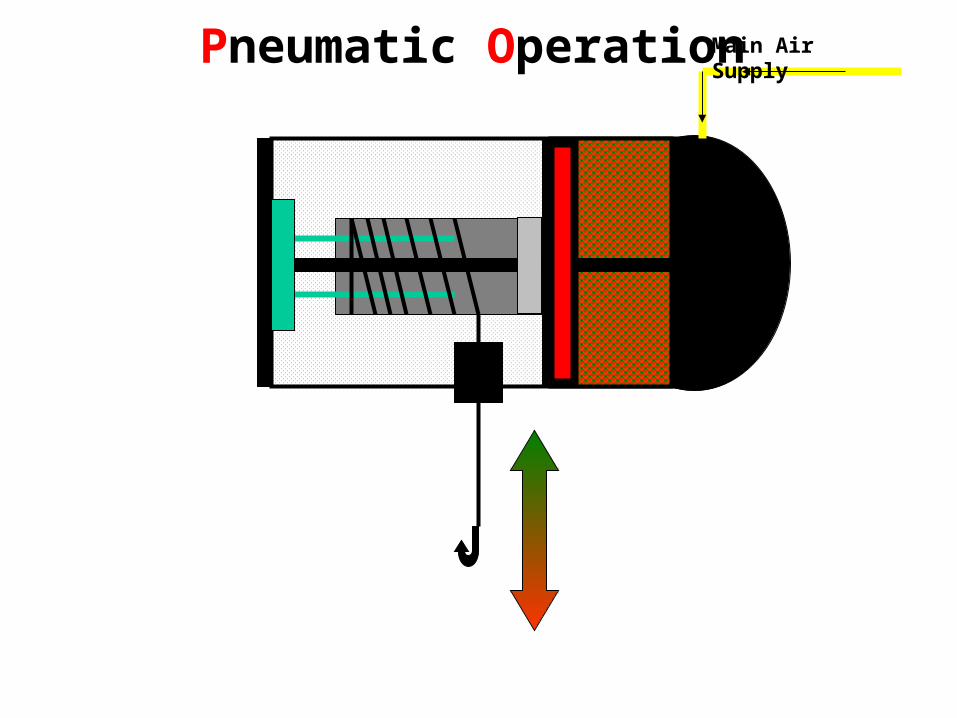
Main Air SupplyPneumatic Operation

Main Air SupplyPneumatic Operation

Z-Brake
• Safety Retraction System
• Centrifugal Force
• Prevents Excessive Upward Acceleration
• Standard On All Units Except 50 lb. Tool Balancer
• Patent No. 5,522,581
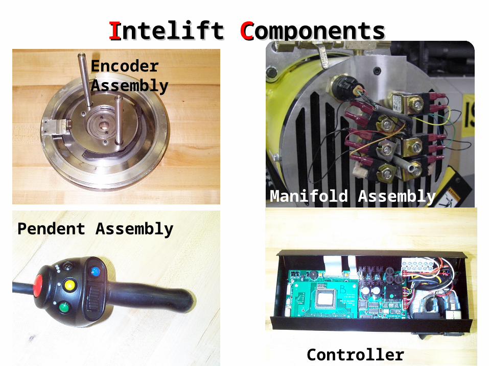
IInteliftntelift C ComponentsomponentsEncoder Assembly
Pendent Assembly
Manifold Assembly
Controller Assembly

IInteliftntelift P Pendentendent
Intelift “ON”
UP/ DOWN
Clamp/Unclamp
Power “ON”
Speed Select
E-Stop
Operator Interface to InteliftOperator Interface to Intelift

IIntelift ntelift FForce orce SSensing ensing CControl ontrol HHandleandle
Force Sensing Load Cell
E-Stop
Operator Interface to InteliftOperator Interface to Intelift
Power “ON”
Up/ Down switch Removed
Speed Select
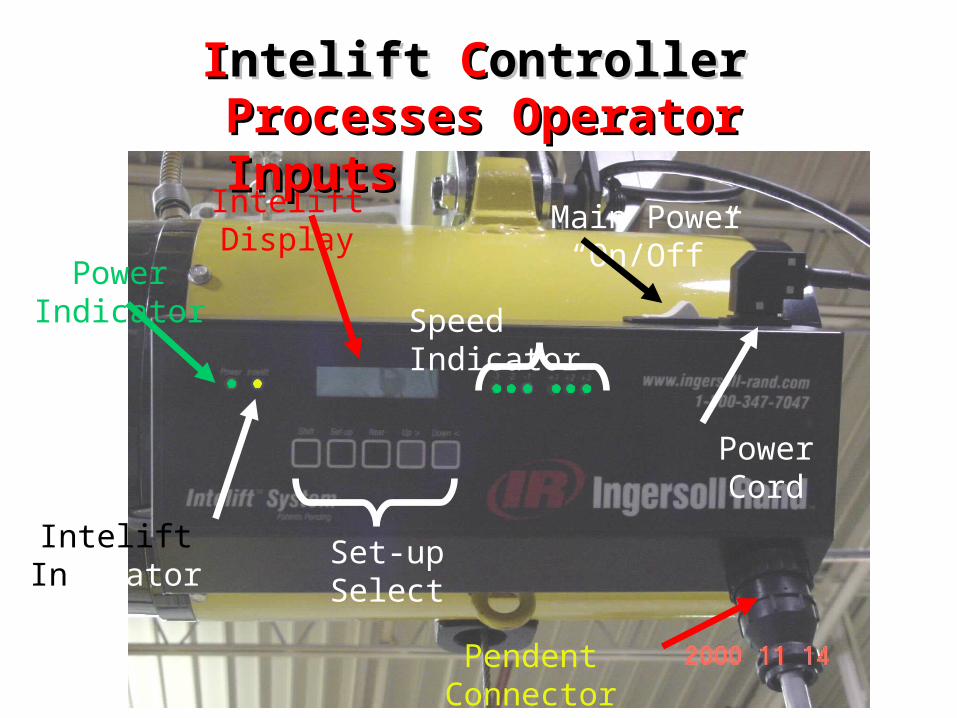
IInteliftntelift C Controllerontroller
Power Indicator
Main Power “On/Off”
Power Cord
Pendent Connector
Intelift Indicator Set-up Select
Speed Indicator
Intelift Display
Processes Operator InputsProcesses Operator Inputs

IInteliftntelift M Manifoldanifold
Up Solenoids
Down SolenoidsPressure Transducer
Senses Pressure/ Controls Air to BalancerSenses Pressure/ Controls Air to Balancer
Air Supply
Manifold Cover

IInteliftntelift E Encoderncoder
Encoder Wheel
Encoder Pick Up
Senses Balancer PositionSenses Balancer Position
EXERCISEEXERCISE
INTELIFT COMPONENTS
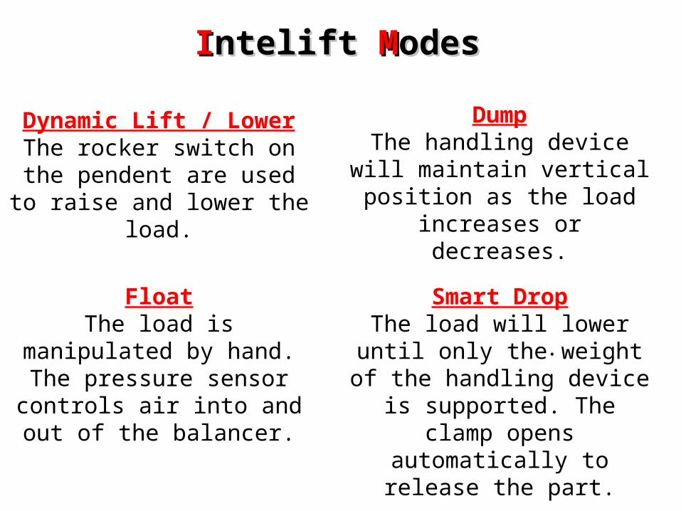
Dynamic Lift / LowerThe rocker switch on the pendent
are used to raise and lower the load.
.
IInteliftntelift M Modesodes
FloatThe load is manipulated by hand. The pressure sensor controls air
into and out of the balancer.
DumpThe handling device will
maintain vertical position as the load increases or decreases.
Smart DropThe load will lower until only
the weight of the handling device is supported. The clamp opens
automatically to release the part.
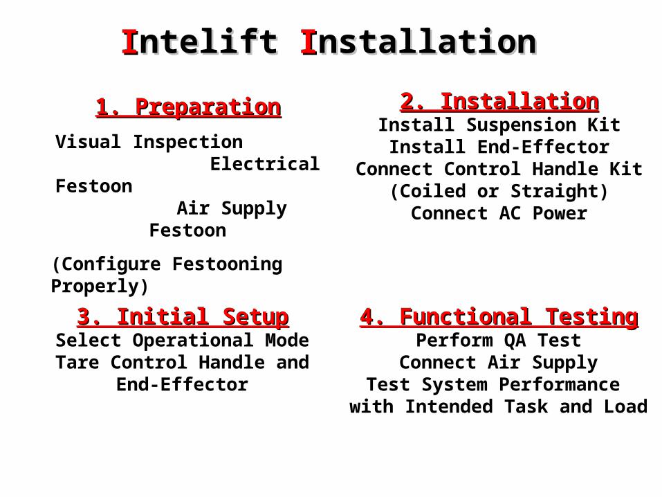
IInteliftntelift I Installationnstallation
1. Preparation1. Preparation
Visual Inspection Electrical Festoon
Air Supply Festoon
(Configure Festooning Properly)
3. Initial Setup3. Initial SetupSelect Operational Mode
Tare Control Handle and End-Effector
2. Installation2. InstallationInstall Suspension KitInstall End-Effector
Connect Control Handle Kit(Coiled or Straight)Connect AC Power
4. Functional Testing4. Functional TestingPerform QA Test
Connect Air SupplyTest System Performance
with Intended Task and Load
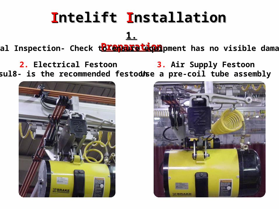
IInteliftntelift I Installationnstallation1.1. Preparation Preparation
1. Visual Inspection- Check to ensure equipment has no visible damage.
2. Electrical FestoonInsul8- is the recommended festoon
3. Air Supply FestoonUse a pre-coil tube assembly

IInteliftntelift I Installationnstallation2.2. Installation Installation
4. Connect Pendent
1. Install Suspension Kit 2. Install to Rail 3. Install End-Effector
5. Connect AC Power

EXERCISEEXERCISE
INTELIFT Modes/ Installation

IInteliftntelift I Installationnstallation3.3. Initial Set up Initial Set up
1. Switch Main Power On and air supply
2. Depress Pendent Power On

Keypad ButtonsKeypad Buttons
“Shift”- Initiates “QA” Testing
“Setup” - Enters and exits you out of the Setup menu
“Next” - Steps through each of four Intelift functions which may be changed
• Control Mode
• Intelift Mode
• Control Handle Tare
• End Effector Tare
“Up/Down” - Selects value or entry for function
IInteliftntelift I Installationnstallation

IInteliftntelift I Installationnstallation3.3. Initial Set up (cont.) Initial Set up (cont.)3. Select Operational Modes 4. Tare End Effector/ Pendent
Press Next to change screens
Press Up/ Down to change selection and tare end effector or pendent
Press Set up to access Operational Mode Select

IInteliftntelift I Installationnstallation4.4. Functional Test Functional Test
Dynamic Lift/ LowerUse the rocker switch to maneuver to the part.
Engage the part.
Depress the UP rocker switch. The end effector and part should lift.
Depress the speed select button until the load moves at a comfortable speed.
Depress the DN rocker to verify that the speed is correct.
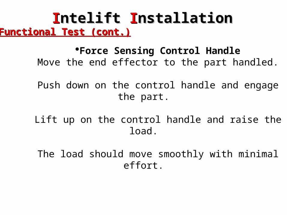
IInteliftntelift I Installationnstallation4.4. Functional Test (cont.) Functional Test (cont.)
Force Sensing Control HandleMove the end effector to the part handled.
Push down on the control handle and engage the part.
Lift up on the control handle and raise the load.
The load should move smoothly with minimal effort.

IInteliftntelift I Installationnstallation4.4. Functional Test (cont.) Functional Test (cont.)
Float ModePush the Intelift button on the pendent.
Engage the part.
Raise the load by lifting the end effector.
Move the load up/down by hand not using the pendent.
The load should move smoothly with minimal effort.
IInteliftntelift I Installationnstallation4.4. Functional Test (cont.) Functional Test (cont.)
Smart Drop ModePush the Intelift button on the pendent
Move the end effector to the part handled.
Engage the part.
Raise the load approximately 6 inches.
Press and release the clamp/unclamp button.
Smart Drop- the load should lower the 6 inches and release the part when supported.

IInteliftntelift I Installationnstallation4.4. Functional Test (cont.) Functional Test (cont.)
Dump ModePush the Intelift button on the pendent
Move the end effector to the part handled.
Engage the part.
Raise the load approximately 12 inches.
Begin dumping the load.
Dump- the load should remain in the same position as the weight decreases.

EXERCISEEXERCISE
INTELIFT Set-up/ Functional test

FFind out as many details about failure:
What happened prior to failure?
Is the unit E-Stopped/ power “on”?
Was anyone operating the unit when it failed?
BBe sure not to overlook the obvious!!
IIf you think you have a suspect part, prove it before you replace it!!
IInteliftntelift T Troubleshootingroubleshooting

IInteliftntelift T Troubleshooting roubleshooting TTableable

IInteliftntelift S Schematicchematic

IInteliftntelift T TroubleshootingroubleshootingIInteliftntelift QA QA SSelf elf TTestest
Press and Release “Power ON”
Remove power from the Intelift with E-Stop
Press and hold the Shift key to start the Self Test

What running “QA” will do for youHelp troubleshoot sensor or control handle communication
problems
Encoder Rocker switch
Pressure SensorDisplay Button
IInteliftntelift T Troubleshootingroubleshooting

IInteliftntelift P Preventive reventive MMaintenanceaintenance

BBalanceralancer P Preventive reventive MMaintenanceaintenance

Intelift Model Configuration
IA W 015 080 A2 1 S P
PENDENT CAPACITY SUSPENSIONOPTION
TRAVELWIRE ROPE VOLTAGEOPTION
Z-STOPOPTION
POWER CORDOPTION
Related Documents