3 Scotchlite ™ Glass Bubbles This guide provides suggestions for the efficient removal of 3M ™ Scotchlite ™ Glass Bubbles from bulk bags (FIBC—Flexible Intermediate Bulk Containers). These are not intended for use as a design specification or operational manual. The user is responsible for determining the method and equipment appropriate for the user’ s oper ation. NOTE: Refer to the Product Label and Material Safety Data Sheet (MSDS) for Product Health and Safety Information on Scotchlite glass bubbles. Refer to the Scotchlite glass bubbles Product Data Sheet for additional storage and handling information. See the appendix for equipment and component considerations. Introduction Bulk Ba g Ba g Unloading Suggestions 3M ™ Scotchlite ™ Glass Bubbles are available in approximately 50 cubic foot (1.41 cubic meter) bulk bags with a polyethylene liner and ten-inch bag lifting loops. The liner has a 22 in (50.56m) diameter by 26 in (0.66m) long discharge spout in the base. The filled bag size is approximately 45 in W x 45 in L x 46 in H (1.14m x 1.14m x 1.17m). Bags are stacked two per pallet then wrapped with a stretch film. The maximum shipped height is 104 in (2.64m). The pallet is a two-way entry type. Typical shipping is in a “high cube” trailer or a 40 foot “high cube” seagoing shipping container. Bags are not returnable.

Welcome message from author
This document is posted to help you gain knowledge. Please leave a comment to let me know what you think about it! Share it to your friends and learn new things together.
Transcript
8/3/2019 Bag Unloading Lit
http://slidepdf.com/reader/full/bag-unloading-lit 1/6
3
Scotchlite™
Glass Bubbles
This guide provides suggestions for the efficient removal of 3M™ Scotchlite™GlassBubbles from bulk bags (FIBC—Flexible Intermediate Bulk Containers). These arenot intended for use as a design specification or operational manual. The user isresponsible for determining the method and equipment appropriate for theuser’s operation.
NOTE: Refer to the Product Label and Material Safety Data Sheet (MSDS) forProduct Health and Safety Information on Scotchlite glass bubbles. Refer to the
Scotchlite glass bubbles Product Data Sheet for additional storage and handlinginformation. See the appendix for equipment and component considerations.
Introduction
Bulk Bag
BagUnloading
Suggestions
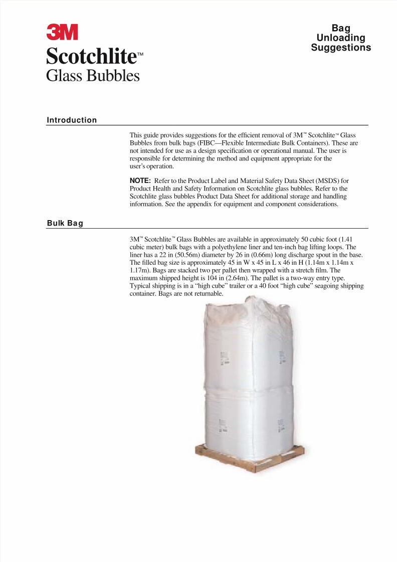
3M™ Scotchlite™ Glass Bubbles are available in approximately 50 cubic foot (1.41cubic meter) bulk bags with a polyethylene liner and ten-inch bag lifting loops. Theliner has a 22 in (50.56m) diameter by 26 in (0.66m) long discharge spout in the base.The filled bag size is approximately 45 in W x 45 in L x 46 in H (1.14m x 1.14m x1.17m). Bags are stacked two per pallet then wrapped with a stretch film. Themaximum shipped height is 104 in (2.64m). The pallet is a two-way entry type.Typical shipping is in a “high cube” trailer or a 40 foot “high cube” seagoing shipping
container. Bags are not returnable.
8/3/2019 Bag Unloading Lit
http://slidepdf.com/reader/full/bag-unloading-lit 2/6
2
Typically, bulk bags are suspended in an unloading station. Material is usuallytransferred by vacuum suction from a vacuum receiver or a double-diaphragmpneumatic pump. Material is pulled through the conveying line, either for apredetermined time or until a desired weight is reached in the stand or the receivingvessel. Using valves the system can supply material to one or more processes. Filtersseparate air from the material in the receiving vessel. The filter is cleaned with pulsed,high-pressure, conditioned, dry air. Dust collection trunks or hoods are usually placed
near the system.
Bulk Bag Discharging
Bulk bags require a lifting frame for handling the bags safely. The lifting frame can beattached to an overhead trolley or placed on a forklift truck.
Do not use clamp forklifts for moving glass bubble-filled bulk bags as they may causebubble breakage or release bubbles into the air.
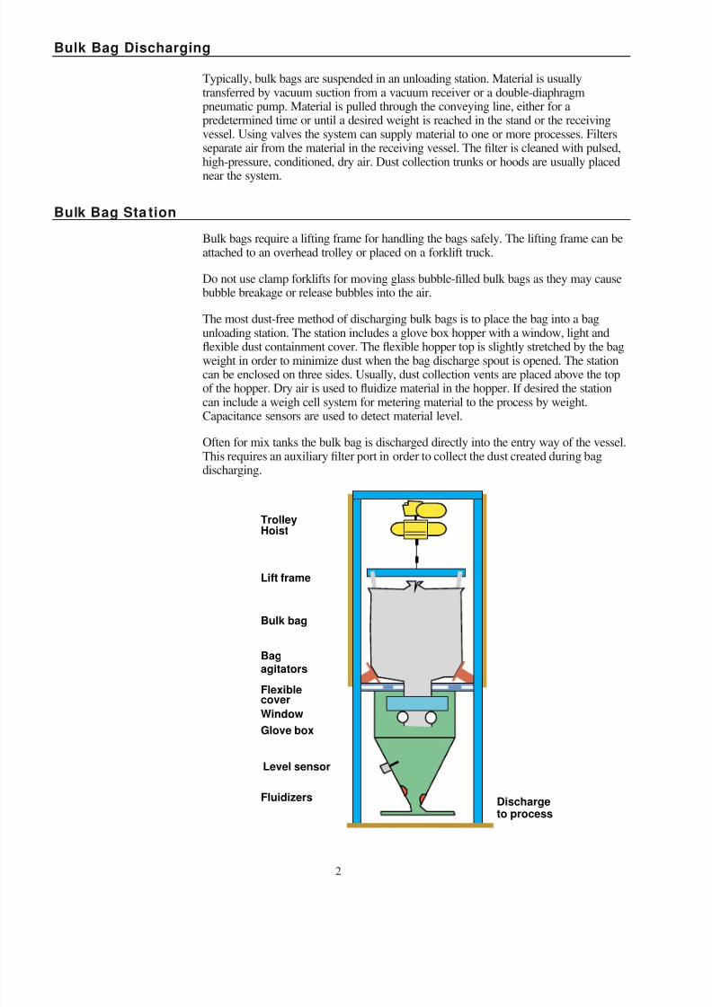
The most dust-free method of discharging bulk bags is to place the bag into a bagunloading station. The station includes a glove box hopper with a window, light and
flexible dust containment cover. The flexible hopper top is slightly stretched by the bagweight in order to minimize dust when the bag discharge spout is opened. The stationcan be enclosed on three sides. Usually, dust collection vents are placed above the topof the hopper. Dry air is used to fluidize material in the hopper. If desired the stationcan include a weigh cell system for metering material to the process by weight.Capacitance sensors are used to detect material level.
Often for mix tanks the bulk bag is discharged directly into the entry way of the vessel.This requires an auxiliary filter port in order to collect the dust created during bagdischarging.
Bulk Bag Sta tion
Trolley
Hoist
Lift frame
Bulk bag
Bagagitators
Flexiblecover
Window
Glove box
Level sensor
Fluidizers Dischargeto process
8/3/2019 Bag Unloading Lit
http://slidepdf.com/reader/full/bag-unloading-lit 3/6
3
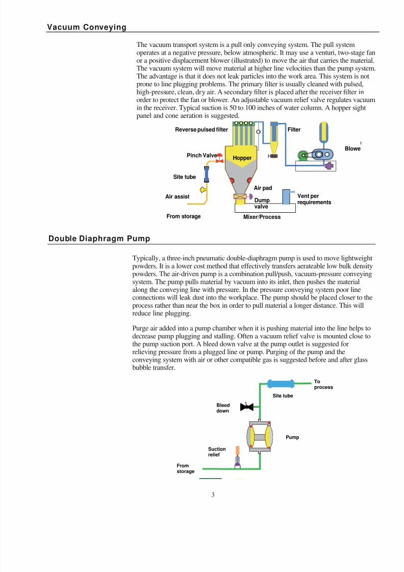
The vacuum transport system is a pull only conveying system. The pull systemoperates at a negative pressure, below atmospheric. It may use a venturi, two-stage fanor a positive displacement blower (illustrated) to move the air that carries the material.The vacuum system will move material at higher line velocities than the pump system.The advantage is that it does not leak particles into the work area. This system is notprone to line plugging problems. The primary filter is usually cleaned with pulsed,high-pressure, clean, dry air. A secondary filter is placed after the receiver filter in
order to protect the fan or blower. An adjustable vacuum relief valve regulates vacuumin the receiver. Typical suction is 50 to 100 inches of water column. A hopper sightpanel and cone aeration is suggested.
Vacuum Conveying
Site tube
Hopper
Vent perrequirements
Pinch Valve
Reverse pulsed filter
Dumpvalve
Mixer/Process
Filter
Blowe
Air assist
From storage
Air pad
Typically, a three-inch pneumatic double-diaphragm pump is used to move lightweightpowders. It is a lower cost method that effectively transfers aerateable low bulk densitypowders. The air-driven pump is a combination pull/push, vacuum-pressure conveyingsystem. The pump pulls material by vacuum into its inlet, then pushes the materialalong the conveying line with pressure. In the pressure conveying system poor line
connections will leak dust into the workplace. The pump should be placed closer to theprocess rather than near the box in order to pull material a longer distance. This willreduce line plugging.
Purge air added into a pump chamber when it is pushing material into the line helps todecrease pump plugging and stalling. Often a vacuum relief valve is mounted close tothe pump suction port. A bleed down valve at the pump outlet is suggested forrelieving pressure from a plugged line or pump. Purging of the pump and theconveying system with air or other compatible gas is suggested before and after glassbubble transfer.
Double Diaphragm Pump
Bleeddown
Fromstorage
Pump
Suctionrelief
Site tube
Toprocess
8/3/2019 Bag Unloading Lit
http://slidepdf.com/reader/full/bag-unloading-lit 4/6
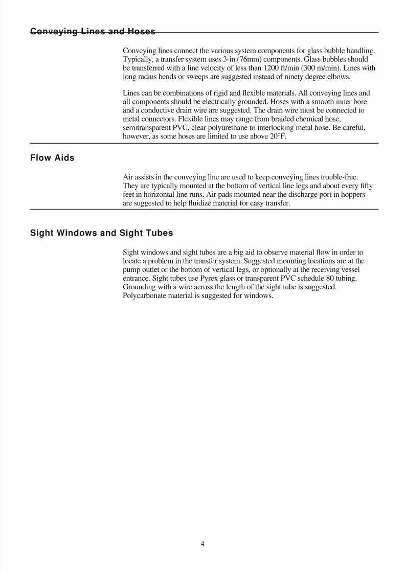
Air assists in the conveying line are used to keep conveying lines trouble-free.They are typically mounted at the bottom of vertical line legs and about every fiftyfeet in horizontal line runs. Air pads mounted near the discharge port in hoppers
are suggested to help fluidize material for easy transfer.
Flow Aids
Conveying lines connect the various system components for glass bubble handling.Typically, a transfer system uses 3-in (76mm) components. Glass bubbles shouldbe transferred with a line velocity of less than 1200 ft/min (300 m/min). Lines withlong radius bends or sweeps are suggested instead of ninety degree elbows.
Lines can be combinations of rigid and flexible materials. All conveying lines and
all components should be electrically grounded. Hoses with a smooth inner boreand a conductive drain wire are suggested. The drain wire must be connected tometal connectors. Flexible lines may range from braided chemical hose,semitransparent PVC, clear polyurethane to interlocking metal hose. Be careful,however, as some hoses are limited to use above 20°F.
Conveying Lines and Hoses
Sight windows and sight tubes are a big aid to observe material flow in order tolocate a problem in the transfer system. Suggested mounting locations are at thepump outlet or the bottom of vertical legs, or optionally at the receiving vesselentrance. Sight tubes use Pyrex glass or transparent PVC schedule 80 tubing.Grounding with a wire across the length of the sight tube is suggested.Polycarbonate material is suggested for windows.
Sight Windows and Sight Tubes
8/3/2019 Bag Unloading Lit
http://slidepdf.com/reader/full/bag-unloading-lit 5/6
The following equipment manufacturers are identified for your convenience. 3Mmakes no representations about the manufacturer or their equipment. The user isresponsible for determining what method and equipment are fit for a particularpurpose and suitable for the user’s application.
SystemsNol-Tec Systems, Inc.425 Apollo DriveLino Lakes, MN 55014Phone: 651-780-8600Website: www.nol-tec.com
Bulk Bag UnloadingCustom Equipment Design1057 Highway 80 EastMonroe, LA 71203Phone: 318-345-2222
Control & Metering6500 Kestrel RoadMississauga, ONT L5T 1Z6Phone: 800-736-5739Website: www.controlandmetering.com
ComponentsMcMaster-Carr Supply Company600 County Line RoadElmhurst, IL 60126-2081Phone: 800-990-7867
Website: www.mcmastercarr.com
Morris Coupling Company2240 West 15th StreetErie, PA 16505Phone: 800-426-1579Website: www.morriscoupling.com
Flow AidsSolimar Pneumatics7256 Commerce CircleMinneapolis, MN 55432Phone: 800-233-7109Website: www.solimarpneumatics.com
Porex Industries500 Bohannon RoadFairburn, GA 30213Phone: 770-964-1421Website: www.porex.com
Double Diaphragm PumpsIngersol Rand Fluid ProductsP.O. Box 151Bryan, OH 43506Phone: 419-636-4242Website: www.arozone.com
Yamada America1200 Nuclear DriveWest Chicago, IL 60185Phone: 800-990-7867Website: www.yamadapump.com
Wilden Pump & Engineering Co.22069 Van Buren StreetGrand Terrace, CA 92313-5607Phone: 909-422-1730Website: www.wilden.com
Sight TubeHarvel Plastics, Inc.P.O. Box 757Easton, PA 18044-0757Phone: 610-252-7355
Website: www.harvel.com
Appendix: Equipment Manufacturers
8/3/2019 Bag Unloading Lit
http://slidepdf.com/reader/full/bag-unloading-lit 6/6
© 2001 3M IPC 98-0212-XXXX-X (HB)
Specialty Materials
3M Center, Building 223-6S-04St. Paul, MN 55144-1000
www.3m.com/microspheres
3
Issued: 04/01
Resources
For further information or sales assistance, please contact:
3M Specialty Materials800 367 8905 Fax 800 810 8514In Canada, 800 410-6880, ext. 6019In Puerto Rico, 809 750 3000
Important Notice to Purchaser: The information in this publication is based on tests that we believe are reliable.Yourresults may vary due to differences in test types and conditions. You must evaluate and determine whether the productis suitable for your intended application. Since conditions of product use are outside of our control and vary widely, thefollowing is made in lieu of all express or implied warranties (including the warranties of merchantability or fitness fora particular purpose): Except where prohibited by law, 3M’s only obligation and your only remedy, is replacement or, at3M's option, refund of the original purchase price of product that is shown to have been defective when you received it.In no case will 3M be liable for any direct, indirect, special, incidental, or consequential damages (including, withoutlimitation, lost profits, goodwill, and business opportunity) based on breach of warranty, condition or contract,negligence, strict tort, or any other legal or equitable theory.
Europe3M Specialty Materials3M Belgium N. V.Haven 1005, Canadastraat 11B-2070 Zwijndrecht32 3 250 7521
3M Canada CompanySpecialty Materials1840 Oxford StreetLondon, OntarioN5V 3R6800 364 3477
Sumitomo 3M Limited33-1, Tamagawadai 2-chomeSetagaya-ku, Tokyo158-8583 Japan813 3709 8250
Asia PacificCall (U.S.) 651 736 7123
United States3M Specialty Materials3M Center, Building 223-6S-04St. Paul, MN55144-1000800 367 8905800 810 8514 (Fax)
Brazil3M DO Brazil LtdaVia Anhanguera, km 11013001-970 SumareSao Paulo, Brazil55 19 3864 7363
Mexico3M Mexico, S.A. de C.V.Avenida Santa Fe #55Col. Santa FeDelegación Alvaro Obregón01210 Mexico, D.F.525 270 0400
Venezuela3M Manufacturera Venezuela, S.A.Final Avenida TamanacoCentro Empresarial El Rosal, Piso 6Urb. El Rosal (Chacao) Caracas 106058 212 957 8111
Gulf3M Gulf, Ltd.4th Floor, Entrance 4Hamarain CenterDeiraDubaiUnited Arab Emirates971 4 265 2121
Argentina3M Argentina S.A.C.I.F.I.ALos Arboles 8421686 HurlinghamProvincia de Buenos AiresArgentina5411 4469 8200
Related Documents