SERVICE MANUAL DATA AZG-1 English CD-R/RW MECHANISM BASIC CD MECHANISM:3ZG-2 E3 KSM-2131FAM TYPE YKZD3RDF ZD3RNDM ZD3RDM YZD3RNDM YZD3RDM ZD3RN1DM YZD3RNMDM YZD3RMDM ZD3RMDM ZD3RMDJM YZD3RNDCM YZD3RDCM ZD4RDC BASIC CD MECHANISM 3ZG-2 E3 KSM-2131 FAM S/M Code No. 09-001-335-3N8

Welcome message from author
This document is posted to help you gain knowledge. Please leave a comment to let me know what you think about it! Share it to your friends and learn new things together.
Transcript

SERVICE MANUAL
DATA
AZG-1 English
CD-R/RW MECHANISMBASIC CD MECHANISM:3ZG-2 E3
KSM-2131FAM
TYPEYKZD3RDFZD3RNDMZD3RDM
YZD3RNDMYZD3RDM
ZD3RN1DMYZD3RNMDMYZD3RMDMZD3RMDMZD3RMDJM
YZD3RNDCMYZD3RDCM
ZD4RDC
BASIC CD MECHANISM
3ZG-2 E3
KSM-2131 FAM
S/M Code No. 09-001-335-3N8

2
PROTECTION OF EYES FROM LASER BEAM DURING SERVICING
VAROITUS!Laiteen Käyttäminen muulla kuin tässä käyttöohjeessa mainit-
ulla tavalla saattaa altistaa käyt-täjän turvallisuusluokan 1 ylit-
tävälle näkymättömälle lasersäteilylle.
VARNING!Om apparaten används på annat sätt än vad som specificeras i
denna bruksanvising, kan användaren utsättas för osynling
laserstrålning, som överskrider gränsen för laserklass 1.
Caution: Invisible laser radiation when
open and interlocks defeated avoid expo-
sure to beam.
Advarsel:Usynling laserståling ved åbning,
når sikkerhedsafbrydere er ude af funktion.
Undgå udsættelse for stråling.
CAUTIONUse of controls or adjustments or performance of procedures
other than those specified herein may result in hazardous
radiation exposure.
ATTENTIONL'utilisation de commandes, réglages ou procédures autres que
ceux spécifiés peut entraîner une dangereuse exposition aux
radiations.
ADVARSEL!Usynlig laserståling ved åbning, når sikkerhedsafbrydereer ude
af funktion. Undgå udsættelse for stråling.
This Compact Disc player is classified as a CLASS 1 LASER
product.
The CLASS 1 LASER PRODUCT label is located on the rear
exterior.
This set employs laser. Therefore, be sure to follow carefully the
instructions below when servicing.
WARNING!WHEN SERVICING, DO NOT APPROACH THE LASER EXIT
WITH THE EYE TOO CLOSELY. IN CASE IT IS NECESSARY TO
CONFIRM LASER BEAM EMISSION. BE SURE TO OBSERVE
FROM A DISTANCE OF MORE THAN 30cm FROM THE
SURFACE OF THE OBJECTIVE LENS ON THE OPTICAL
PICK-UP BLOCK.
CLASS 1KLASSE 1LUOKAN 1KLASS 1
LASER PRODUCTLASER PRODUKTLASER LAITELASER APPARAT
Precaution to replace Optical block(KSS-213F)
1) After the connection, remove solder shown inthe right figure.
Body or clothes electrostatic potential could ruinlaser diode in the optical block. Be sure groundbody and workbench, and use care the clothesdo not touch the diode.

3
How to Adjust the Rotating Phase of theGear, Main Cam
1) Push down the hooking catch of the CHAS. MECH, andremove the TRAY.
2) Align the arrow mark of the Gear, Main Cam with the blackround mark of the CHAS, MECHA as shown below.
3) Confirm that the Slide, Mech Cam is located in the rightposition, then insert the TRAY gently.
Caution: If the rotating phase of the Gear, Main Cam isincorrectly adjusted, the chucking operation andtray movement will have malfunction.
Align the arrow 2 mark with the blackround • mark.

4
REF. NO PART NO. KANRI DESCRIPTIONNO.
REF. NO PART NO. KANRI DESCRIPTIONNO.
ELECTRICAL MAIN PARTS LIST
IC
87-A21-381-040 C-IC,LA9235M 87-A21-591-010 C-IC,LC78641NE-D 87-A21-414-010 IC,BA5927S
TRANSISTOR
87-026-609-080 TR,KTA1266GR 87-A30-076-080 C-TR,2SC3052F 87-026-214-080 TR,DTA114YS (0.3W) 87-A30-515-080 TR,2SA1979 O/Y 87-A30-087-080 C-FET,2SK2158
87-026-237-080 CHIP-TR,DTC124XK<EXCEPT ZD3RN1DM,YZD3RNDCM,YZD3RNMDM,ZD3RNDM,YZD3RNDM>
87-A30-075-080 C-TR,2SA1235F
DIODE
87-A40-270-080 C-DIODE,MC2838 87-070-136-080 ZENER,MTZJ5.1B 87-A40-003-080 ZENER,MTZJ4.3A 87-A40-337-080 ZENER,MTZJ 6.8B 87-A40-313-080 C-DIODE,MC 2840
3CD C.B
C1 87-010-374-080 CAP, ELECT 47-10V C2 87-010-196-020 C-CAP,S 0.1-25 Z F GRM
<EXCEPT YZD3RNDCM,YZD3RDCM,YKZD3RDF,ZD4RDC> C2 87-010-196-080 CHIP CAPACITOR,0.1-25
<YZD3RNDCM,YZD3RDCM,YKZD3RDF,ZD4RDC> C3 87-010-260-080 CAP, ELECT 47-25V C4 87-010-260-080 CAP, ELECT 47-25V
C5 87-010-197-020 C-CAP,S 0.01-25 B<EXCEPT YZD3RNDCM,YZD3RDCM,YKZD3RDF,ZD4RDC>
C5 87-010-197-080 CAP, CHIP 0.01 DM<YZD3RNDCM,YZD3RDCM,YKZD3RDF,ZD4RDC>
C6 87-010-405-080 CAP, ELECT 10-50V C7 87-010-263-080 CAP, ELECT 100-10V C8 87-012-349-080 C-CAP,S 1000P-50 CH
C10 87-010-546-080 CAP, ELECT 0.33-50V C11 87-010-401-080 CAP, ELECT 1-50V C13 87-010-321-020 C-CAP,S 82P-50 CH
<EXCEPT YZD3RNDCM,YZD3RDCM,YKZD3RDF,ZD4RDC> C13 87-010-321-080 CHIP CAPACITOR,82P(J)
<YZD3RNDCM,YZD3RDCM,YKZD3RDF,ZD4RDC> C15 87-010-197-020 C-CAP,S 0.01-25 B
<EXCEPT YZD3RNDCM,YZD3RDCM,YKZD3RDF,ZD4RDC>
C15 87-010-197-080 CAP, CHIP 0.01 DM<YZD3RNDCM,YZD3RDCM,YKZD3RDF,ZD4RDC>
C16 87-010-260-080 CAP, ELECT 47-25V C101 87-010-992-080 C-CAP,S 0.047-25 B C102 87-010-401-080 CAP, ELECT 1-50V C103 87-010-196-020 C-CAP,S 0.1-25 Z F GRM
<EXCEPT YZD3RNDCM,YZD3RDCM,YKZD3RDF,ZD4RDC>
C103 87-010-196-080 CHIP CAPACITOR,0.1-25<YZD3RNDCM,YZD3RDCM,YKZD3RDF,ZD4RDC>
C104 87-010-196-020 C-CAP,S 0.1-25 Z F GRM<EXCEPT YZD3RNDCM,YZD3RDCM,YKZD3RDF,ZD4RDC>
C104 87-010-196-080 CHIP CAPACITOR,0.1-25<YZD3RNDCM,YZD3RDCM,YKZD3RDF,ZD4RDC>
C105 87-010-260-080 CAP, ELECT 47-25V C106 87-010-322-080 C-CAP,S 100P-50 CH
<YZD3RNDCM,YZD3RDCM,YKZD3RDF,ZD4RDC>
C106 87-010-322-020 C-CAP,S 100P-50 CH<EXCEPT YZD3RNDCM,YZD3RDCM,YKZD3RDF,ZD4RDC>
C107 87-010-196-020 C-CAP,S 0.1-25 Z F GRM<EXCEPT YZD3RNDCM,YZD3RDCM,YKZD3RDF,ZD4RDC>
C107 87-010-196-080 CHIP CAPACITOR,0.1-25<YZD3RNDCM,YZD3RDCM,YKZD3RDF,ZD4RDC>
C108 87-010-186-020 C-CAP,S 4700P-50 B<EXCEPT YZD3RNDCM,YZD3RDCM,YKZD3RDF,ZD4RDC>
C108 87-010-186-080 CAP,CHIP 4700P<YZD3RNDCM,YZD3RDCM,YKZD3RDF,ZD4RDC>
C109 87-010-992-080 C-CAP,S 0.047-25 B C110 87-010-322-080 C-CAP,S 100P-50 CH
<YZD3RNDCM,YZD3RDCM,YKZD3RDF,ZD4RDC> C110 87-010-322-020 C-CAP,S 100P-50 CH
<EXCEPT YZD3RNDCM,YZD3RDCM,YKZD3RDF,ZD4RDC> C111 87-010-260-080 CAP, ELECT 47-25V C112 87-010-197-020 C-CAP,S 0.01-25 B
<EXCEPT YZD3RNDCM,YZD3RDCM,YKZD3RDF,ZD4RDC>
C112 87-010-197-080 CAP, CHIP 0.01 DM<YZD3RNDCM,YZD3RDCM,YKZD3RDF,ZD4RDC>
C114 87-010-260-080 CAP, ELECT 47-25V C115 87-010-197-020 C-CAP,S 0.01-25 B
<EXCEPT YZD3RNDCM,YZD3RDCM,YKZD3RDF,ZD4RDC> C115 87-010-197-080 CAP, CHIP 0.01 DM
<YZD3RNDCM,YZD3RDCM,YKZD3RDF,ZD4RDC> C116 87-010-260-080 CAP, ELECT 47-25V
C117 87-010-197-020 C-CAP,S 0.01-25 B<EXCEPT YZD3RNDCM,YZD3RDCM,YKZD3RDF,ZD4RDC>
C117 87-010-197-080 CAP, CHIP 0.01 DM<YZD3RNDCM,YZD3RDCM,YKZD3RDF,ZD4RDC>
C118 87-010-263-080 CAP, ELECT 100-10V C119 87-015-819-080 CAPACITOR,0.01 C120 87-010-312-080 C-CAP,S 15P-50 CH
<YZD3RNDCM,YZD3RDCM,YKZD3RDF,ZD4RDC>
C120 87-010-312-020 C-CAP,S 15P-50 J CH<EXCEPT YZD3RNDCM,YZD3RDCM,YKZD3RDF,ZD4RDC>
C121 87-010-312-080 C-CAP,S 15P-50 CH<YZD3RNDCM,YZD3RDCM,YKZD3RDF,ZD4RDC>
C121 87-010-312-020 C-CAP,S 15P-50 J CH<EXCEPT YZD3RNDCM,YZD3RDCM,YKZD3RDF,ZD4RDC>
C122 87-010-404-080 CAP, ELECT 4.7-50V C123 87-010-197-020 C-CAP,S 0.01-25 B
<EXCEPT YZD3RNDCM,YZD3RDCM,YKZD3RDF,ZD4RDC>
C123 87-010-197-080 CAP, CHIP 0.01 DM<YZD3RNDCM,YZD3RDCM,YKZD3RDF,ZD4RDC>
C124 87-010-401-080 CAP, ELECT 1-50V C126 87-010-196-020 C-CAP,S 0.1-25 Z F GRM
<EXCEPT YZD3RNDCM,YZD3RDCM,YKZD3RDF,ZD4RDC> C126 87-010-196-080 CHIP CAPACITOR,0.1-25
<YZD3RNDCM,YZD3RDCM,YKZD3RDF,ZD4RDC> C128 87-010-196-020 C-CAP,S 0.1-25 Z F GRM
<EXCEPT YZD3RNDCM,YZD3RDCM,YKZD3RDF,ZD4RDC>
C128 87-010-196-080 CHIP CAPACITOR,0.1-25<YZD3RNDCM,YZD3RDCM,YKZD3RDF,ZD4RDC>
C130 87-010-196-020 C-CAP,S 0.1-25 Z F GRM<EXCEPT YZD3RNDCM,YZD3RDCM,YKZD3RDF,ZD4RDC>
C130 87-010-196-080 CHIP CAPACITOR,0.1-25<YZD3RNDCM,YZD3RDCM,YKZD3RDF,ZD4RDC>
C132 87-010-405-080 CAP, ELECT 10-50V C133 87-010-314-020 C-CAP,S 22P-50 CH
<EXCEPT YZD3RNDCM,YZD3RDCM,YKZD3RDF,ZD4RDC>
C133 87-010-314-080 C-CAP,S 22P-50V<YZD3RNDCM,YZD3RDCM,YKZD3RDF,ZD4RDC>
C135 87-A11-088-080 CAP,TC U 100P-50 J CH C151 87-010-405-080 CAP, ELECT 10-50V C152 87-010-405-080 CAP, ELECT 10-50V C192 87-012-349-080 C-CAP,S 1000P-50 CH
C193 87-010-196-020 C-CAP,S 0.1-25 Z F GRM<EXCEPT YZD3RNDCM,YZD3RDCM,YKZD3RDF,ZD4RDC>
C193 87-010-196-080 CHIP CAPACITOR,0.1-25<YZD3RNDCM,YZD3RDCM,YKZD3RDF,ZD4RDC>
C201 87-A10-730-080 CAP,E 1000-16 SMG C202 87-010-196-020 C-CAP,S 0.1-25 Z F GRM
<EXCEPT YZD3RNDCM,YZD3RDCM,YKZD3RDF,ZD4RDC> C202 87-010-196-080 CHIP CAPACITOR,0.1-25
<YZD3RNDCM,YZD3RDCM,YKZD3RDF,ZD4RDC>
C204 87-010-196-020 C-CAP,S 0.1-25 Z F GRM<EXCEPT YZD3RNDCM,YZD3RDCM,YKZD3RDF,ZD4RDC>
C204 87-010-196-080 CHIP CAPACITOR,0.1-25<YZD3RNDCM,YZD3RDCM,YKZD3RDF,ZD4RDC>
C205 87-010-405-080 CAP, ELECT 10-50V C206 87-010-405-080 CAP, ELECT 10-50V C207 87-010-196-020 C-CAP,S 0.1-25 Z F GRM
<EXCEPT YZD3RNDCM,YZD3RDCM,YKZD3RDF,ZD4RDC>

5
REF. NO PART NO. KANRI DESCRIPTIONNO.
REF. NO PART NO. KANRI DESCRIPTIONNO.
• Regarding connectors, they are not stocked as they are not the initial order items.The connectors are available after they are supplied from connector manufacturers upon the order is received.
C207 87-010-196-080 CHIP CAPACITOR,0.1-25<YZD3RNDCM,YZD3RDCM,YKZD3RDF,ZD4RDC>
C301 87-010-382-080 CAP, ELECT 22-25V C302 87-010-196-020 C-CAP,S 0.1-25 Z F GRM
<EXCEPT YZD3RNDCM,YZD3RDCM,YKZD3RDF,ZD4RDC> C302 87-010-196-080 CHIP CAPACITOR,0.1-25
<YZD3RNDCM,YZD3RDCM,YKZD3RDF,ZD4RDC> C303 87-010-260-080 CAP, ELECT 47-25V
C401 87-010-322-020 C-CAP,S 100P-50 CH<EXCEPT YZD3RNDCM,YZD3RDCM,YKZD3RDF,ZD4RDC>
C401 87-010-322-080 C-CAP,S 100P-50 CH<YZD3RNDCM,YZD3RDCM,YKZD3RDF,ZD4RDC>
C402 87-010-322-020 C-CAP,S 100P-50 CH<EXCEPT YZD3RNDCM,YZD3RDCM,YKZD3RDF,ZD4RDC>
C402 87-010-322-080 C-CAP,S 100P-50 CH<YZD3RNDCM,YZD3RDCM,YKZD3RDF,ZD4RDC>
C403 87-010-322-020 C-CAP,S 100P-50 CH<EXCEPT YZD3RNDCM,YZD3RDCM,YKZD3RDF,ZD4RDC>
C403 87-010-322-080 C-CAP,S 100P-50 CH<YZD3RNDCM,YZD3RDCM,YKZD3RDF,ZD4RDC>
C404 87-010-322-080 C-CAP,S 100P-50 CH<YZD3RNDCM,YZD3RDCM,YKZD3RDF,ZD4RDC>
C404 87-010-322-020 C-CAP,S 100P-50 CH<EXCEPT YZD3RNDCM,YZD3RDCM,YKZD3RDF,ZD4RDC>
C405 87-010-322-020 C-CAP,S 100P-50 CH<EXCEPT YZD3RNDCM,YZD3RDCM,YKZD3RDF,ZD4RDC>
C405 87-010-322-080 C-CAP,S 100P-50 CH<YZD3RNDCM,YZD3RDCM,YKZD3RDF,ZD4RDC>
C406 87-010-322-020 C-CAP,S 100P-50 CH<EXCEPT YZD3RNDCM,YZD3RDCM,YKZD3RDF,ZD4RDC>
C406 87-010-322-080 C-CAP,S 100P-50 CH<YZD3RNDCM,YZD3RDCM,YKZD3RDF,ZD4RDC>
C407 87-010-405-080 CAP, ELECT 10-50V C454 87-010-196-020 C-CAP,S 0.1-25 Z F GRM
<EXCEPT YZD3RNDCM,YZD3RDCM,YKZD3RDF,ZD4RDC> C454 87-010-196-080 CHIP CAPACITOR,0.1-25
<YZD3RNDCM,YZD3RDCM,YKZD3RDF,ZD4RDC>
C601 87-010-260-080 CAP, ELECT 47-25V C602 87-010-196-020 C-CAP,S 0.1-25 Z F GRM
<EXCEPT YZD3RNDCM,YZD3RDCM,YKZD3RDF,ZD4RDC> C602 87-010-196-080 CHIP CAPACITOR,0.1-25
<YZD3RNDCM,YZD3RDCM,YKZD3RDF,ZD4RDC> CN1 87-A60-429-010 CONN,16P H TOC-A CN201 84-ZG1-648-010 CONN ASSY,6P<ZD4RDC>
CN201 87-099-199-010 CONN,6P 6216 H<EXCEPT ZD4RDC> CN202 87-A60-130-010 CONN,5P V FE CN301 87-A60-154-010 CONN,6P H FE CN601 87-009-345-010 CONN,2P PH H
<YZD3RMDM,YZD3RNMDM,ZD3RMDM,ZD3RMDJM> CON401 87-099-030-010 CONN,13P 6216H
FB601 87-008-372-080 FILTER, EMI BL OIRNI<YZD3RMDM,YZD3RNMDM,ZD3RMDM,ZD3RMDJM>
FB602 87-008-372-080 FILTER, EMI BL OIRNI LED601 87-A40-558-010 LED,SLZ-8128A-01-A M201 87-045-305-010 MOTOR, RF-500TB DC-5V (2MA)
<EXCEPT ZD4RDC> M201 87-045-383-010 MOT,M9I50T28-2<ZD4RDC>
SW201 87-036-109-010 PUSH SWITCH SW202 87-036-109-010 PUSH SWITCH X101 87-A70-046-010 VIB,XTAL 16.934MHZ
LED C.B<YZD3RDCM,YZD3RMDM,ZD3RMDM,ZD3RMDJM,ZD3RDM,YZD3RDM,YKZD3RDF>
LED501 87-A40-263-080 LED,SLH-56PCT31 GRN<YZD3RDCM,YZD3RMDM,ZD3RMDM,ZD3RMDJM,ZD3RDM,YZD3RDM,YKZD3RDF>
LED502 87-A40-263-080 LED,SLH-56PCT31 GRN<YZD3RDCM,YZD3RMDM,ZD3RMDM,ZD3RMDJM,ZD3RDM,YZD3RDM,YKZD3RDF>
LED503 87-A40-268-080 LED,SLH-56DCT31 ORN<YZD3RDCM,YZD3RMDM,ZD3RMDM,ZD3RMDJM,ZD3RDM,YZD3RDM,YKZD3RDF>
LED503 87-A40-263-080 LED,SLH-56PCT31 GRN<ZD4RDC> LED504 87-A40-268-080 LED,SLH-56DCT31 ORN
<EXCEPT ZD3RN1DM,YZD3RNDCM,ZD3RNDM,YZD3RNDM>
T-T C.B
C401 87-A11-148-080 CAP,TC U 0.1-50 Z F CON401 86-NFZ-675-010 CONN,5P H 6216-11H M401 87-045-364-010 MOTOR(BCH3B14) PS401 87-026-573-010 SNSR,PHOTO GP1S53V
DRIVE C.B<EXCEPT ZD4RDC>
M1 87-045-358-010 MOT,RF-310TA 43<EXCEPT ZD4RDC> M2 87-045-356-010 MOT,RF-310TA 30<EXCEPT ZD4RDC> PIN3 87-A60-086-010 CONN,6P H6216-11<EXCEPT ZD4RDC> SW1 87-A90-042-010 SW,LEAF MSW-17310MVP0
<EXCEPT ZD4RDC>
MOTOR C.B<ZD4RDC>
M2 9X-262-513-210 SLED MOTOR<ZD4RDC> PIN3 91-564-722-110 CONNECTOR 6P<ZD4RDC> SW1 91-572-085-110 LEAF SW<ZD4RDC>
6
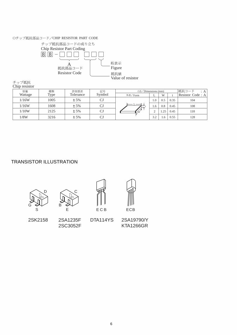
TRANSISTOR ILLUSTRATION
ECBE C BEB
C
2SA1235F2SC3052F
2SA19790/YKTA1266GR
SG
D
2SK2158 DTA114YS
8 8
A
Resistor Code
Chip Resistor Part Coding
Figure
Value of resistor
Chip resistor
Wattage Type Tolerance
1/16W
1/10W
1/8W
1608
2125
3216
5%
5%
5%
CJ
CJ
CJ
Form L W t
1.6 0.8 0.45
2 1.25 0.45
3.2 1.6
108
118
128
: A : A
CHIP RESISTOR PART CODE
0.55
Resistor CodeDimensions (mm)
Symbol
1/16W 1005 5% CJ 1.0 0.5 0.35 104L
t
W

87
BLOCK DIAGRAM
CON401P
IN3
RVDD
TDO
LCH
O
RC
HO
LVS
S,
RV
SSX
OU
T
XIN
LC78641NE-D
ZD3RNMDMZD3RMDM
YZD3RMDMZD3RMDJM
ZD4RDCMODEL
ZD3RDMYZD3RDMZD3RMDMYZD3RMDMZD3RMDJMZD3RDCMYKZD3RDFZD4RDCMODEL
DRIVE C.B (EXCEPT ZD4RDC)MOTOR C.B (ZD4RDC)
KSS-213F
*
LED501, 502
LED503, 504
ZD4RDCEXCEPTZD4RDC
*:
CD MECHANISMEXCEPT ZD4RDC: 3ZG-2E3ZD4RDC: KSM-2131FAM

1 2 3 4 5 6 7 8 9 10 11 12 13 14
A
B
C
D
E
F
G
H
I
J
K
109
WIRING
TO MOTOR C.B PIN3
TO DRIVE C.BPIN3
KSS-213F
ZD3RDMYZD3RDMZD3RMDMYZD3RMDMZD3RMDJMZD3RDCMYKZD3RDFZD4RDCMODEL
ZD3RNMDMZD3RMDMYZD3RMDMZD3RMDJMZD4RDCMODEL
ZD3RDMYZD3RDMZD3RMDMYZD3RMDMZD3RMDJMZD3RDCMYKZD3RDFMODEL
EXCEPTZD4RDC MODEL
ZD4RDC MODEL
ZD4RDC MODEL EXCEPT ZD4RDC MODEL

1211
SCHEMATIC DIAGRAM
M201MOVE3.6V
VDD/2V
IC101LC78641NE-D ZD3RNMDM
ZD3RMDMYZD3RMDMZD3RMDJMZD4RDCMODEL
ZD3RDMYZD3RDMZD3RMDMYZD3RMDMZD3RMDJMZD3RDCMYKZD3RDFZD4RDCMODEL
2S
A1
97
90
/Y
2S
A1
97
90
/Y
2S
A1
97
90
/Y
2S
A1
97
90
/Y
2S
A1
97
90
/Y
DRIVE C.B (EXCEPT ZD4RDC)MOTOR C.B (ZD4RDC)
KSS-213F
*
*
LED501LED502R503LED504LED503
R504
SLH-56PCT31GRN
150 1/8WSLH-56DCT31ORNSLH-56DCT31ORNSLH-56PCT31GRN150 1/8W
EXCEPTZD4RDC
ZD4RCD
*:
CONN 6P (EXCEPT ZD4RDC)CONN ASSY 6P (ZD4RDC)
EXCEPT ZD4RDC: 3ZG-2E3ZD4RDC: KSM-2131 FAM

1413
1. How to Start the CD Test Mode
While pressing the CD function key, connect the AC power plug to wall outlet.The test mode starts up and “CD TEST” appears on the display.
2. How to Exit the CD Test Mode
Press the POWER button or disconnect the AC power plug from wall outlet.* When any function key other than PLAY is pressed during playback, the test mode is canceled.
3. Function and Use of the CD Test Mode
TEST MODE
NO
1
2
3
4
5
6
7
MODE
Start mode
Search mode
Play mode
Traverse mode
Sled mode
Spindle mode
RF AGC mode
How to enter the
mode
STOP button
PLAY button
PAUSE button
FF button
RWD button
TAPE REC
button
TUNER button
Display
All indicators turn
on
CD
Normal
Normal
CD TEST
CD TEST
All indicators turn
on
AGC ON/OFF
Operation
• All FL all ndicators turn on
• LD turns on all the time
• Focus search continuos
operation *1
• Spindle motor continuos
kick
• Normal playback
• Focus search is continued if
failed in TOC READ.
• Tracking servo OFF/ON
Repeats OFF/ON every time
the PAUSE button is
pressed
• Moves PU to inner
circumference *2
Kicks the lens to inner
circumference at the same
time
• Moves PU to outer
circumference *2
Kicks the lens to outer
circumference at the same
time
• Pressing the button once
rotates the spindle motor in
the normal direction (rough
speed). Pressing the button
again rotates it in the reverse
direction. Pressing it again
stops the motor
• Repeats ON/OFF every time
the TUNER button is
pressed
Check item
• FL check
• Microprocessor check
• APC circuit check
• Laser current measurement
• Focus search waveform
check
• Focus error waveform check
(Ignores DRF during search
mode)
• Each servo circuit is checked
• DRF check
• Tracking balance check
• Sled circuit check
• Tracking circuit check
• Mechanism operation check
• PU check
• Spindle circuit check
• Spindle motor check
• PU good or defective check
• RF AMP circuit check
*1 ...... When the focus search keeps running for 10 minutes or longer continuously, the driver IC heats up, and the protective circuit worksso that the machine may stops operating.In this case, turn off the main power, wait for a while and restart the machine.
*2 ...... Do not keep pressing the FF or RWD button while the pickup is located at the innermost or outermost circumference because thegear can be damaged as the sled motor keeps rotating.
4. Automatic Adjustment Result Display
The automatic adjustment values of the focus and the tracking can be displayed.
4-1. Automatic Adjustment Result Display of Focus Offset Cancel/Gain
1) Enter the start mode (all indicators turn on).2) Press the TAPE button to display “F**” and set each of the adjustment item to either ON or OFF. (Refer to the following
table.)3) Press the PLAY button to play back the CD.4) Press the CD button.5) The automatic adjustment value “F** **” is displayed. (Refer to the following table.)6) Upon completion of check, press the CD button twice to return to the play mode.
4-2. Automatic Adjustment Result Display of Tracking Offset Cancel/Balance/Gain
1) Enter the start mode (all indicators turn on).2) Press the AUX button to display “T***” and set each adjustment item to either ON or OFF. (Refer to the following table.)3) Press the PLAY button to play back the CD.4) Press the CD button twice.5) The automatic adjustment value “F******” is displayed. (Refer to the following table.)6) Upon completion of check, press the CD button to return to the play mode.
Adjustment item (ON = 1, OFF = 0)Automatic adjustment value display
(Asterisk * means hexadecimal display.)
F OFFSET GAIN F OFFSET — GAIN
F 0 0 F Not displayed Not displayed Not displayed
F 1 1 F ** Not displayed **
F 1 0 F ** Not displayed Not displayed
F 0 1 F Not displayed Not displayed **
Adjustment item (ON = 1, OFF = 0)Automatic adjustment value display
(Asterisk * means hexadecimal display.)
T OFFSET BALANCE GAIN T OFFSET BALANCE GAIN
T 0 0 0 T Not displayed Not displayed Not displayed
T 1 1 1 T ** ** **
T 1 1 0 T ** ** Not displayed
T 1 0 1 T ** Not displayed **
T 1 0 0 T ** Not displayed Not displayed
T 0 1 1 T Not displayed ** **
T 0 1 0 T Not displayed ** Not displayed
T 0 0 1 T Not displayed Not displayed **

15
WAVE FORM
1 IC201 • (IN6-R) VOLT/DIV: 500mVTIME/DIV: 200mS
2 IC201 ª (IN6-F)
1.6Vp-p
1.6Vp-p
1
2
3 Between CN202 1 and 2 VOLT/DIV: 1V(2 Pin: 0 Level) TIME/DIV: 200mS
0
4 IC101 % (FE) VOLT/DIV: 500mVTIME/DIV: 2mS
1.75Vp-p
5 IC101 ̂ (TE) VOLT/DIV: 200mVTIME/DIV: 200µS
1.0Vp-p

16
IC BLOCK DIAGRAMIC, BA5927S
IC, LA9235M

17
PDO1
PDO2
VVSS
PCKIST
VVDD
FR
HFL
SLCIST
SLCO
EFMIN
JITTV
JITTC
BH
PH (RFENV)
FE
TE
VREF
ADAVDD
ADAVSS
PHREF
BHREF
TBLO
TDO
FDO
SPDO
SLDO
DVREF/FG
LASER
CONT1
CONT2
CONT3
CONT4
CONT5
PCK
C2F
VDD
DOUT
FSX
1
2
3
4
5
6
7
8
9
10
11
12
13
14
15
16
17
18
19
20
21
22
23
24
25
26
27
28
29
30
31
32
33
34
35
36
37
38
IC, LC78641NE-DIC DESCRIPTION
O
O
—
—
—
—
I
—
O
I
O
O
I
I
I
I
I
—
—
O
O
O
O
O
O
O
I/O
O
I/O
I/O
I/O
I/O
I/O
O
O
—
O
O
Internal VCO control phase comparator output pin. (Pull down)
Internal VCO control phase comparator output pin.
OFF for rough servo, ON for phase servo. (Pull down)
Internal VCO ground pin.
PDO output current adjustment resistor connection pin.
Internal VCO power supply pin.
VCO frequency range adjustment resistor connection pin. (Pull up)
Mirror detection signal input pin.
SLCO output current adjustment resistor connection pin.
Control output.
EFM signal input pin.
Jitter detection monitor pin.
Jitter detection adjustment pin. (Pull down)
BH signal input pin. (Connected to GND)
PH signal or RFENV signal input pin.
FE signal input pin.
TE signal input pin.
VREF input pin.
Servo A/D, D/A power supply pin.
Servo A/D, D/A ground pin.
PH reference output pin. (Not connected)
BH reference output pin. (Not connected)
Tracking balance output pin.
Tracking control output pin.
Focus control output pin.
Spindle control output pin.
Thread control output pin.
Output driver VREF output pin. FG signal input pin. (Connected to GND)
Laser ON/OFF control pin.
General-purpose input/output pin 1. (Connected to GND)
General-purpose input/output pin 2. (Connected to GND)
General-purpose input/output pin 3. (Connected to GND) (Not connected)
General-purpose input/output pin 4.
General-purpose input/output pin 5. (Not connected)
EFM data playback clock monitor pin. Average 4.3218MHz when the phase is locked.
(Not connected)
C2 flag output pin. (Not connected)
Digital power supply pin.
Digital out output pin. (EIAJ format)
Output pin for the 7.35kHz synchronization signal divided from the crystal oscillator.
(Not connected)
Pin No. Pin Name I/O Description

18
EFLG
TEST
EMPH
MUTEL
MUTER
LVDD
LCHO
LVSS
RVSS
RCHO
RVDD
XVDD
XIN
XOUT
XVSS
ASLRCK
ASDACK
ASDFIN
LRSY
DATACK
DATA
16M
SFSY
SBSY
PW
SBCK
CE
CL
DI
DO
INT
WRQ
RES
DRF
VDD5V
VSS
CONT6
CONT7
V/P
39
40
41
42
43
44
45
46
47
48
49
50
51
52
53
54
55
56
57
58
59
60
61
62
63
64
65
66
67
68
69
70
71
72
73
74
75
76
77
O
I
I/O
O
O
—
O
—
—
O
—
—
I
O
—
I
I
I
O
O
O
O
O
O
O
I
I
I
I
O
O
O
I
O
—
—
I/O
I/O
O
C1, C2 error correction monitor pin. (Not connected)
Test input pin. (Connected to GND)
Emphasis pin. Which becomes an input pin after reset and can be controlled externally.
This becomes an emphasis monitor pin under control by command. (Not connected)
L channel mute output pin. (Not connected)
R channel mute output pin. (Not connected)
L channel power supply pin.
L channel output pin.
L channel ground pin.
R channel ground pin.
R channel output pin.
R channel power supply pin.
Crystal oscillator power supply pin.
Connections for a 16.9344MHz crystal oscillator pin.
Crystal oscillator ground pin.
L/R clock input pin. (Connected to GND)
Bit clock input pin. (Connected to GND)
L/R channel data input pin. (Connected to GND)
L/R clock output pin. (Not connected)
Bit clock output pin. (Not connected)
L/R channel data output pin. (Not connected)
16.9344MHz output pin. (Not connected)
Subcode frame synchronization signal output pin. This signal falls when the subcode is
in the standby state. (Not connected)
Subcode clock synchronization signal output pin. (Not connected)
Subcode P, Q, R, S, T, U and W output pin. (Not connected)
Subcode readout clock input pin. (Connected to GND)
Chip enable signal input pin.
Data transfer clock input pin.
Data input pin.
Data output pin.
Interruption signal output pin. (Not connected)
Interruption signal output pin.
Reset input pin. This pin must be set low briefly after power is first applied.
Focus ON detect pin.
Microprocessor interface power supply.
Digital ground pin.
General-purpose input/output pin 6.
General-purpose input/output pin 7.
Rough servo/phase control automatic switching monitor output pin.
“H” for rough servo and “L” for phase servo. (Not connected)
Pin No. Pin Name I/O Description

19
FSEQ
DEFECT
EFMO
78
79
80
Synchronization signal detection output pin.
Outputs a high level when the synchronization signal detected from the EFM signal
and the internally generated synchronization signal agree. (Not connected)
Defect pin. Which becomes an input pin after reset and can be controlled externally.
This becomes the defect monitor pin under control by command. (Not connected)
EFM signal output pin. (Not connected)
O
I/O
O
Pin No. Pin Name I/O Description

20
MECHANICAL EXPLODED VIEW 1/1
EXCEPT ZD4 : 3ZG-2 E3ZD4 : KSM-2131FAM
A
B
C
1
43
P.C.B
ZZJ-J
32
CUSHION,CD A
CUSHION,CD A
CUSHION,CD A
P.C.B
5
7
8
9
a
a
10
11
12
13
14
15
15
33 (EXCEPT ZD4)
17
18
4
21
22
23
24
25
26
27
28 2930
19
31
20
2
6
34
16

21
REF. NO PART NO. KANRI DESCRIPTIONNO.
REF. NO PART NO. KANRI DESCRIPTIONNO.
MECHANICAL PARTS LIST 1/1
Basic color symbol Color Basic color symbol Color Basic color symbol ColorB Black C Cream D OrangeG Green H Gray L BlueLT Transparent Blue N Gold P PinkR Red S Silver ST Titan SilverT Brown V Violet W White
WT Transparent White Y Yellow YT Transparent YellowLM Metallic Blue LL Light Blue GT Transparent GreenLD Dark Blue DT Transparent Orange
COLOR NAME TABLE
1 84-ZG1-225-010 BELT,SQ1.0-63.3 2 84-ZG1-673-010 F-CABLE,5P 1.25 210MM BLACK N
<EXCEPT YZD3RNMDM,ZD3RNDM,YZD3RNDM,ZD4RDC> 2 84-ZG1-672-010 F-CABLE,5P 1.25 210MM WHITE N
<YZD3RNMDM,ZD3RNDM,YZD3RNDM,ZD4RDC> 3 87-045-364-010 MOTOR(BCH3B14) 4 84-ZG1-267-010 PULLEY,LOAD MO 8<EXCEPT YKZD3RDF>
4 81-ZG1-212-010 PULLY,LOAD MO<YKZD3RDF> 5 84-ZG1-238-010 GEAR,WORM N 6 84-ZG1-248-010 SPR-C,WORM 7 84-ZG1-239-210 PULLY,WORM N<EXCEPT ZD4RDC> 7 84-ZG1-273-010 PULLEY,WORM 4<ZD4RDC>
8 8A-ZG1-001-010 TRAY,NO3 BLU 9 84-ZG1-291-110 HLDR,MAGNET 4 NAT
<EXCEPT YKZD3RDF,ZD4RDC> 9 84-ZG1-272-110 HLDR,MAGNET N4<YKZD3RDF,ZD4RDC> 10 84-ZG1-259-010 SPR-P,WORM 11 84-ZG1-221-010 GEAR,MAIN TT<YKZD3RDF>
11 84-ZG1-269-010 GEAR,MAIN TT 4<EXCEPT YKZD3RDF> 12 84-ZG1-224-010 LEVER,TT
<EXCEPT YZD3RNDCM,YZD3RNMDM,ZD3RNDM,YZD3RNDM> 12 84-ZG1-288-010 LEVER,TT NAT
<YZD3RNDCM,YZD3RNMDM,ZD3RNDM,YZD3RNDM> 13 8A-ZG1-002-010 TURN TABLE,NO1 BLU 14 81-ZG1-239-010 S-SCREW,TT
15 81-ZG1-271-010 S-SCREW MECH REAR 16 85-NFT-611-110 FF-CABLE 16P-1.0
<YZD3RNDCM,YZD3RDCM,ZD4RDC> 16 85-NFT-611-110 FF-CABLE 16P-1.0
<EXCEPT YZD3RNDCM,YZD3RDCM,ZD4RDC> 17 84-ZG1-287-010 HLDR,MECHA NAT
<YZD3RNDCM,YZD3RNMDM,ZD3RNDM,YZD3RNDM> 17 84-ZG1-212-210 HLDR,MECHA NO2
<EXCEPT YZD3RNDCM,YZD3RNMDM,ZD3RNDM,YZD3RNDM>
18 87-045-305-010 MOTOR, RF-500TB DC-5V (2MA)<EXCEPT ZD4RDC>
18 87-045-383-010 MOT,M9I50T28-2<ZD4RDC> 19 84-ZG1-211-010 SPR-E CAM S 20 84-ZG1-285-010 PLATE,MAGNET BLK<ZD3RN1DM> 20 81-ZG1-255-110 PLATE,MAGNET MK2<EXCEPT ZD3RN1DM>
21 83-ZG3-604-010 RING,MAG 2 22 83-ZG3-213-010 LVR,SW 23 84-ZG1-208-210 LEVER,CAM<YKZD3RDF,ZD4RDC> 23 84-ZG1-266-010 LEVER,CAN 8
<EXCEPT YKZD3RDF,ZD4RDC> 24 84-ZG1-205-210 GEAR,TRAY (*)
25 81-ZG1-291-110 GEAR,TRAY RELAY NO3<EXCEPT ZD4RDC>
25 81-ZG1-250-110 GEAR,TRAY RELAY MK2*<ZD4RDC> 26 84-ZG1-206-110 GEAR,RELAY<YKZD3RDF,ZD4RDC> 26 84-ZG1-274-010 GEAR,RELAY 8
<EXCEPT YKZD3RDF,ZD4RDC> 27 84-ZG1-207-010 PULLEY,RELAY<EXCEPT ZD4RDC>
27 84-ZG1-271-010 PULLEY,RELAY 8<ZD4RDC> 28 84-ZG1-209-010 BELT,SQ1.8-117.7 29 84-ZG1-203-410 GEAR,MAIN CAM
<YZD3RNDCM,YZD3RNMDM,ZD3RNDM,YZD3RNDM> 29 84-ZG1-215-410 GEAR,MAIN CAM BLU
<EXCEPT YZD3RNDCM,YZD3RNMDM,ZD3RNDM,YZD3RNDM> 30 84-ZG1-011-010 REFLECTOR,CD
<EXCEPT ZD3RN1DM,YZD3RNDCM,YZD3RNMDM,ZD3RNDM,YZD3RNDM>
31 84-ZG1-216-310 SLIDE,MECHA CAM YEL<EXCEPT YZD3RNDCM,YZD3RNMDM,ZD3RNDM,YZD3RNDM>
31 84-ZG1-204-310 SLIDER,MECHA CAM<YZD3RNDCM,YZD3RNMDM,ZD3RNDM,YZD3RNDM>
32 84-ZG1-201-410 CHAS,MECHA<EXCEPT YZD3RNDCM,YZD3RNMDM,ZD3RNDM,YZD3RNDM,ZD4RDC>
32 84-ZG1-286-010 CHAS,MECHA NAT<YZD3RNDCM,YZD3RNMDM,ZD3RNDM,YZD3RNDM>
32 84-ZG1-232-210 CHAS,MECHA N<ZD4RDC>
33 84-ZG1-630-010 CABLE FFC 6P-1.25<YZD3RNDCM,YZD3RDCM>
33 84-ZG1-630-010 CABLE FFC 6P-1.25<EXCEPT YZD3RNDCM,YZD3RDCM,ZD4RDC>
34 8A-ZG1-208-010 SH, 18-26-0.5 W/ADH BLK A 87-067-703-010 TAPPING SCREW, BVT2+3-10
<EXCEPT ZD3RN1DM,YZD3RNDCM,YZD3RNMDM,ZD3RNDM,YZD3RNDM> B 87-067-981-010 BVT2+3-6 BLK
C 87-251-070-410 U+2.6-3<ZD4RDC>
22
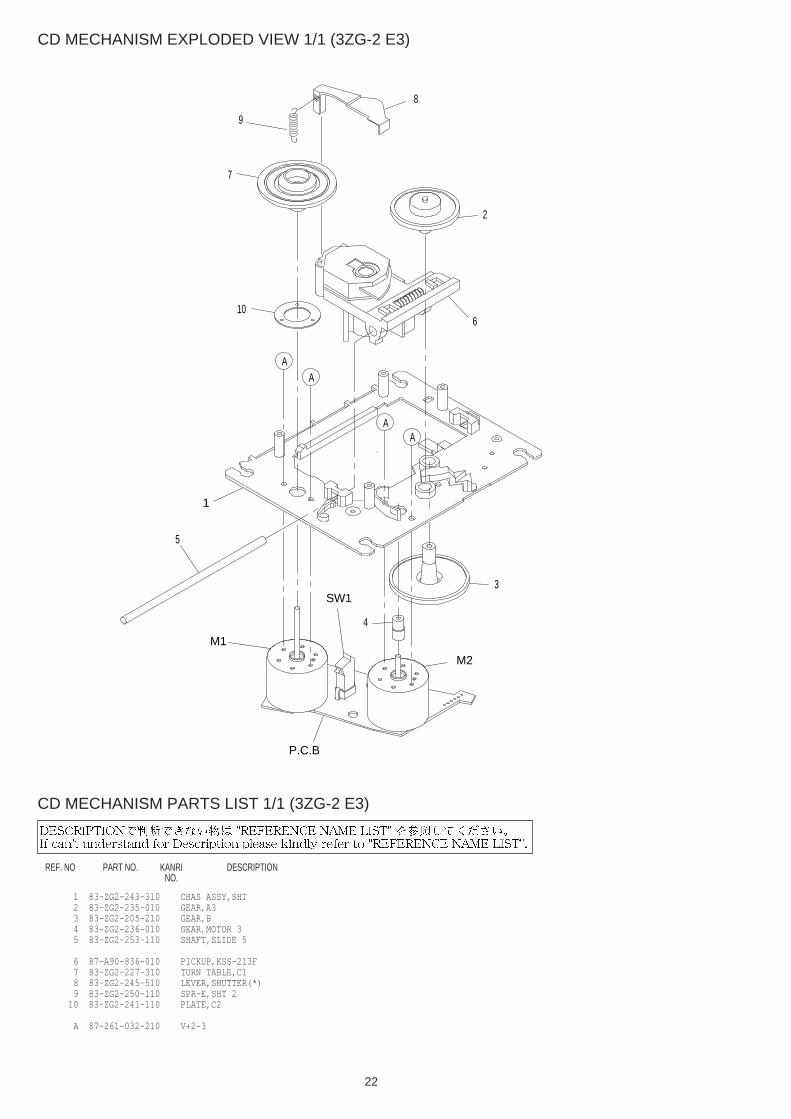
CD MECHANISM EXPLODED VIEW 1/1 (3ZG-2 E3)
CD MECHANISM PARTS LIST 1/1 (3ZG-2 E3)
REF. NO PART NO. KANRI DESCRIPTIONNO.
1 83-ZG2-243-310 CHAS ASSY,SHT 2 83-ZG2-235-010 GEAR,A3 3 83-ZG2-205-210 GEAR,B 4 83-ZG2-236-010 GEAR,MOTOR 3 5 83-ZG2-253-110 SHAFT,SLIDE 5
6 87-A90-836-010 PICKUP,KSS-213F 7 83-ZG2-227-310 TURN TABLE,C1 8 83-ZG2-245-510 LEVER,SHUTTER(*) 9 83-ZG2-250-110 SPR-E,SHT 2 10 83-ZG2-241-110 PLATE,C2
A 87-261-032-210 V+2-3
P.C.B
M1
M2
SW1
1
7
4
2
3
5
6
AA
AA
8
9
10
23
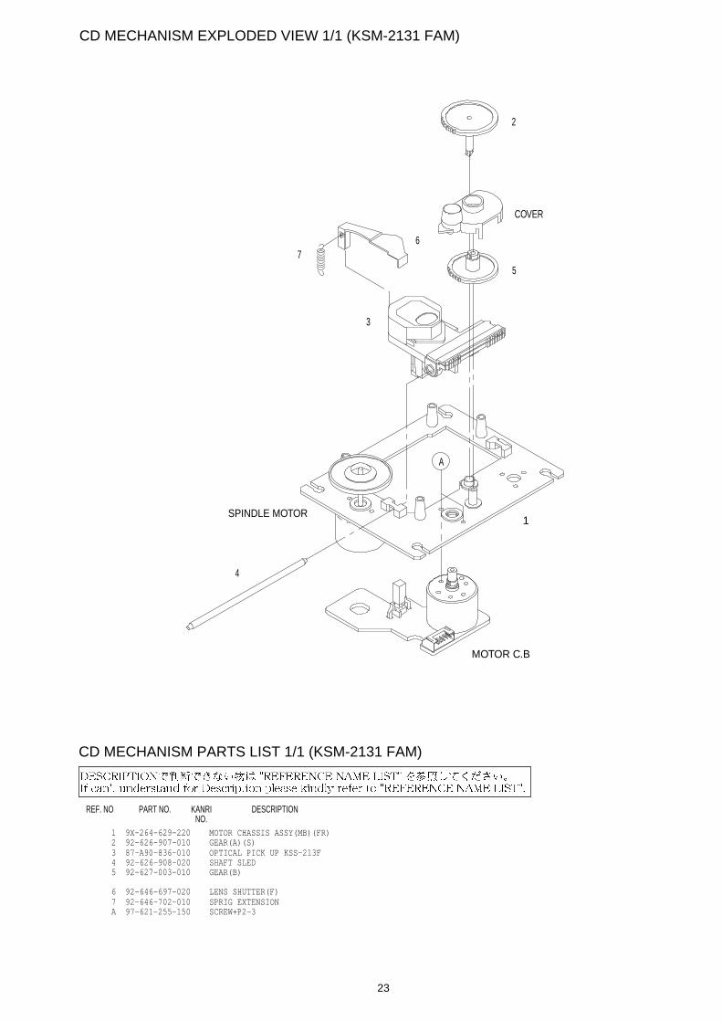
CD MECHANISM EXPLODED VIEW 1/1 (KSM-2131 FAM)
REF. NO PART NO. KANRI DESCRIPTIONNO.
CD MECHANISM PARTS LIST 1/1 (KSM-2131 FAM)
1 9X-264-629-220 MOTOR CHASSIS ASSY(MB)(FR) 2 92-626-907-010 GEAR(A)(S) 3 87-A90-836-010 OPTICAL PICK UP KSS-213F 4 92-626-908-020 SHAFT SLED 5 92-627-003-010 GEAR(B)
6 92-646-697-020 LENS SHUTTER(F) 7 92-646-702-010 SPRIG EXTENSION A 97-621-255-150 SCREW+P2-3
1
2
COVER
3
4
5
SPINDLE MOTOR
MOTOR C.B
A
67

0251431 Printed in Singapore
2–11, IKENOHATA 1–CHOME, TAITO-KU, TOKYO 110-8710, JAPAN TEL:03 (3827) 3111
Related Documents