AVANCE Site Planning for AVANCE Systems 400-700 MHz with Ascend Aeon (actively refrigerated) Magnets User Manual Version 008 Innovation with Integrity ● NMR

Welcome message from author
This document is posted to help you gain knowledge. Please leave a comment to let me know what you think about it! Share it to your friends and learn new things together.
Transcript

AVANCESite Planning for AVANCE Systems 400-700 MHzwith Ascend Aeon (actively refrigerated) MagnetsUser ManualVersion 008
Innovation with Integrity
●
NMR

Copyright © by Bruker Corporation
All rights reserved. No part of this publication may be reproduced, stored in a retrievalsystem, or transmitted, in any form, or by any means without the prior consent of thepublisher. Product names used are trademarks or registered trademarks of their re-spective holders.
This manual was written by
Daniel Baumann and Stanley J. Niles
© January 13, 2017 Bruker Corporation
Document Number: 10000055449
P/N: H157655
For further technical assistance for this product, please do not hesitate to contact yournearest BRUKER dealer or contact us directly at:
Bruker Corporationam Silberstreifen76287 RheinstettenGermanyPhone: + 49 721 5161 6155E-mail: [email protected]: www.bruker.com

Contents
H157655_1_008 iii
Contents1 Introduction......................................................................................................................................... 7
1.1 Units Used Within This Manual........................................................................................... 7
2 Safety................................................................................................................................................... 92.1 Transport and Rigging Safety ............................................................................................. 92.2 The Magnetic Field ............................................................................................................. 92.2.1 Exclusion Zone ................................................................................................................. 102.2.2 Security Zone.................................................................................................................... 102.2.3 The 0.5 mT (5 Gauss) Line ............................................................................................... 112.2.4 Standards on Health and Safety in the Workplace ........................................................... 122.3 Ventilation ......................................................................................................................... 142.3.1 Regular Ventilation............................................................................................................ 142.3.2 Emergency Ventilation ...................................................................................................... 142.3.3 Oxygen Level Sensors...................................................................................................... 152.4 Safe Handling of Cryogenic Substances .......................................................................... 152.4.1 What is a Quench ............................................................................................................. 152.4.2 Liquid Helium Refills ......................................................................................................... 162.5 Earthquake Safety ............................................................................................................ 162.6 Safety from Nearby Construction...................................................................................... 172.7 Country-Specific Safety Regulations ................................................................................ 172.8 Emergency Planning......................................................................................................... 172.8.1 Fire Department Notification ............................................................................................. 18
3 System Components........................................................................................................................ 193.1 Superconducting Magnet Components............................................................................. 193.2 Console and Other System Components ......................................................................... 203.3 CryoProbe System (Optional) ........................................................................................... 213.4 CryoProbe Prodigy System (Optional).............................................................................. 223.5 Other Optional Components ............................................................................................. 23
4 Magnet Access and Rigging............................................................................................................ 254.1 Considerations for Off-loading on Site .............................................................................. 254.2 Considerations for Transport to the NMR laboratory ........................................................ 264.3 Transport Dimensions and Weights.................................................................................. 264.3.1 Magnet Transport Dimensions.......................................................................................... 264.3.2 Magnet Stand Transport Dimensions ............................................................................... 274.3.3 Magnet Transport Weights................................................................................................ 284.3.4 Spectrometer and Accessories Transport Dimensions and Weights................................ 294.4 Rigging Equipment............................................................................................................ 31
5 Ceiling Height Requirements .......................................................................................................... 335.1 Helium Transfer Line......................................................................................................... 345.2 Minimum Ceiling Height .................................................................................................... 36
6 Magnetic Stray Fields....................................................................................................................... 396.1 Horizontal Stray Fields...................................................................................................... 40

Contents
iv H157655_1_008
6.2 Vertical Stray Fields .......................................................................................................... 416.3 Stray Field Plots................................................................................................................ 42
7 Environment and Site Survey Measurement ................................................................................. 437.1 Vibrations .......................................................................................................................... 437.1.1 Integrated Isolator Options................................................................................................ 447.1.2 General Vibration Guidelines ............................................................................................ 447.1.3 Measuring Floor Vibrations ............................................................................................... 467.1.4 Bruker NMR Floor Vibration Guidelines............................................................................ 467.1.5 Floor Vibration Guidelines: Bruker Nano-C and Nano-D .................................................. 487.1.6 Floor Vibration Guidelines: Bruker Nano-C API Damping System ................................... 497.2 Magnetic Environment ...................................................................................................... 517.2.1 Guidelines for Static Objects............................................................................................. 517.2.2 Guidelines for Moving Objects .......................................................................................... 517.3 Electromagnetic Interference ............................................................................................ 527.3.1 Types of EMF Interference ............................................................................................... 527.3.2 DC EMF Interference ........................................................................................................ 527.3.2.1 Measuring DC Fluctuating Fields...................................................................................... 537.3.2.2 Guidelines for DC Interference ......................................................................................... 537.3.2.3 Reducing DC Interference ................................................................................................ 537.3.3 AC EMF Interference ........................................................................................................ 547.3.3.1 Measuring AC EMF Interferences..................................................................................... 547.3.3.2 Guidelines for AC EMF Interference ................................................................................. 547.3.3.3 Reducing AC EMF Interference ........................................................................................ 557.3.4 HF Interference ................................................................................................................. 557.3.4.1 Measuring HF Fluctuating Fields ...................................................................................... 557.3.4.2 Most Commonly Studied Nuclei........................................................................................ 567.3.4.3 Guidelines for HF Interference.......................................................................................... 567.3.4.4 Reducing HF Interference................................................................................................. 56
8 Utility Requirements......................................................................................................................... 578.1 Electrical Power Requirements......................................................................................... 578.2 Telecommunication........................................................................................................... 598.3 Compressed Gas .............................................................................................................. 598.3.1 General Requirements...................................................................................................... 598.3.2 Gas Supply ....................................................................................................................... 598.3.3 Other Specifications.......................................................................................................... 608.3.4 Compressed Air System ................................................................................................... 618.3.4.1 Air Compressors ............................................................................................................... 628.3.4.2 Dryers ............................................................................................................................... 638.3.4.3 Filters ................................................................................................................................ 648.4 Cooling Water ................................................................................................................... 648.5 Lighting ............................................................................................................................. 658.6 HVAC (Heating Ventilation Air Conditioning) .................................................................... 658.6.1 Heat Dissipation into the Room ........................................................................................ 678.6.2 System Stability ................................................................................................................ 678.7 Emergency Ventilation During Installation and Quenches................................................ 688.7.1 Emergency Exhaust Solutions .......................................................................................... 69

Contents
H157655_1_008 v
8.8 Fire Detection System and Fire Extinguishers.................................................................. 71
9 Floor Plan .......................................................................................................................................... 739.1 Magnet Location ............................................................................................................... 739.2 Dimensions and Mass of Equipment ................................................................................ 749.3 Floor Load......................................................................................................................... 749.4 Floor Types ....................................................................................................................... 769.5 Magnet Pits ....................................................................................................................... 769.6 Magnet Platform................................................................................................................ 779.7 Helium Flex Lines ............................................................................................................. 779.8 Maximum Field Strengths for NMR Equipment................................................................. 789.9 Cabinet Position................................................................................................................ 789.10 Worktable Position ............................................................................................................ 789.11 Service Access Requirements .......................................................................................... 799.12 Layout Examples .............................................................................................................. 80
10 CryoProbe and Other Accessories ................................................................................................. 8310.1 CryoCooling Unit............................................................................................................... 8510.2 Helium Compressors ........................................................................................................ 8510.2.1 Available Models............................................................................................................... 8510.2.1.1 Helium Compressor - Indoor Water Cooled...................................................................... 8610.2.1.2 Helium Compressor - Indoor Air Cooled ........................................................................... 8810.2.1.3 Helium Compressor - Outdoor Air Cooled ........................................................................ 8810.2.2 Space Requirements and Specifications .......................................................................... 8910.2.2.1 Indoor Helium Compressors ............................................................................................. 8910.2.2.2 Outdoor Helium Compressors .......................................................................................... 9010.3 Helium Cylinders............................................................................................................... 9110.4 Summary of CryoProbe Options ....................................................................................... 9110.5 CryoProbe Prodigy System (Optional).............................................................................. 9310.6 CryoFit .............................................................................................................................. 9510.6.1 Introduction ....................................................................................................................... 9510.6.2 Installation Requirements ................................................................................................. 95
11 Installation......................................................................................................................................... 9711.1 Overview ........................................................................................................................... 9711.2 Accessibility ...................................................................................................................... 9711.3 Installation Requirements Checklist.................................................................................. 9811.4 Installation Procedure ....................................................................................................... 9811.4.1 Magnet Assembly ............................................................................................................. 9811.4.2 Magnet Evacuation and Flushing with Nitrogen Gas ........................................................ 9911.4.3 Cooling the Magnet to Liquid Nitrogen Temperature ........................................................ 9911.4.4 Cooling the Magnet to Liquid Helium Temperatures......................................................... 9911.4.5 Charging the Magnet ........................................................................................................ 99
12 Contact ............................................................................................................................................ 101
List of Figures................................................................................................................................. 103
List of Tables .................................................................................................................................. 105
Index ................................................................................................................................................ 107

Contents
vi H157655_1_008

Introduction
H157655_1_008 7
1 IntroductionThis manual contains information about site planning and preparation prior to delivery of aBruker AVANCE system. The manual should be read through carefully as mistakes madeinitially may be costly to remedy at a later stage.The systems covered by this manual are AVANCE spectrometers in the range of 400-700MHz with Ascend Aeon (actively refrigerated) magnets.The chapters within this manual deal with various points that need to be considered forsuccessful system operation. They have been included to familiarize you with generalprinciples of successful site planning. For specific questions that may not be addressed inthis manual, or for further information on a topic, do not hesitate to contact your local Brukeroffice. Please also review the Installation Questionaire at the end of the manual.
1.1 Units Used Within This ManualThe SI Unit Tesla (mT) is used throughout this manual whenever magnetic field strengths arediscussed. Some readers may however be more familiar with the Gauss (G) Unit.For comparison the conversion fact is: 1 mT=10 GLikewise the unit kilowatt is used for the measure of heat energy (e.g. amount of heatgenerated by a device per hour). Some readers may be more familiar with thesemeasurements in BTU/hour:For comparison the conversion factor is: 1 BTU/hour=0.000293 kW.(BTU = British Thermal Unit which is the required heat to raise 1 pound of H2O by 1 degreeFahrenheit).Wherever possible both the metric and American (North and South) measure units have beenused throughout this manual. In most cases the weights and measures have been roundedupwards where necessary. The following table offers the common metric to Americanconversion factors used in this manual:
Measure Metric Units American StandardUnits
Conversion Factor(rounded to nearesthundredth)
Linear meter (m)centimeter (cm)
feet (ft.)inch (in.)
1 m = 3.28 ft.1 m = 39.37 in.1 cm = 0.394 in.
Distance kilometer (km) mile (mi.) 1 km = 0.62 mi.
Area square meter (m2) square foot (ft2) 1 m2 = 10.76 ft2
Volume cubic meter (m3)liter (l)
cubic foot (ft3)quart (qt.)
1 m3 = 35.32 ft3
1 l = 1.06 qt. (liquid)
Weight kilogram (kg) pounds (lbs.) 1 kg. = 2.21 lbs.
Pressure bar pounds/square inch(psi)atmosphere (ATM)
1 bar = 14.51 psi1 bar = 0.99 ATM(standard)
Flow (e.g. gasflow)
cubic meter/minute(m3/min.)
cubic feet/minute (ft3/min.)
1 m3/min. = 35.32 ft3/min.
Temperature °C °F F = C × 1.8 + 32

Introduction
8 H157655_1_008
Measure Metric Units American StandardUnits
Conversion Factor(rounded to nearesthundredth)
°F °C C = (F - 32) / 1.8
°C K K = C + 273.15
K °C C = K - 273.15
°F K K = (F + 459.67) / 1.8
K °F F = K × 1.8 - 459.67
Magnet FieldStrength
Tesla (T) Gauss (G) 1 T = 104G
Heat Energy BTU/hour kW 1 BTU/hour =0.000293 kW
BTU = British Thermal Unit which is the required heat to raise 1 pound of H20 by 1 degreeFahrenheit.SI = International System of Units.
Table 1.1: Metric to American Conversion Factors

Safety
H157655_1_008 9
2 SafetyThese safety notes must be read and understood by everyone who comes into contact withsuperconducting magnet systems. Proper training is required for all people having access tosuch systems. It is essential that clear information signs are placed and maintained toeffectively warn people that they are entering a hazardous area.Please refer to Bruker’s General Safety Considerations for the Installation andOperation of Superconducting Magnets, available from Bruker.
2.1 Transport and Rigging SafetyThe following safety notices pertain to the transport and rigging of Avance systems:
• The magnet should always be transported gently in an upright position.• The magnets are sensitive to shocks and tilting, thus are fitted with shock and tilt watches
during transportation.• Only certified operators of fork lifts, pallet jacks and cranes should handle the transport
and rigging.• Crates should not be left outside, but should be brought inside immediately to protect
equipment.• Storage conditions:
– Temperature: 5-40 °C– Humidity: < 50% at 23 °C
2.2 The Magnetic FieldSince the magnetic field of the magnet system is three dimensional, consideration must begiven to floors above and below the magnet, as well as to the surrounding space on the floorthe magnet resides on. The magnetic field exerts attractive forces on equipment and objectsin its vicinity. These forces, which increase drastically approaching the magnet, may becomestrong enough to move large equipment and to cause small objects or equipment to becomeprojectiles.It is important to consider personnel and equipment in the rooms above, below, andadjacent to the room where the magnet will be located:

Safety
10 H157655_1_008
Figure 2.1: Stronger Stray Fields in Vertical Direction than in Horizontal Direction
The magnetic field may affect the operation of electronic medical implants such as pacemakers, if exposed to fields greater than 5 Gauss. Medical implants such as aneurysmclips, surgical clips or prostheses may also be attracted. Further care must be taken aroundchanging fields (e.g. pulsed gradient fields). Eddy currents could be generated in the implantresulting in heat generation and/or unwanted torques.Ensure that all loose ferromagnetic objects are outside the 5 Gauss (0.5 mT) field zone ofthe magnet before the magnet is ramped to field. Human experience and reaction speed aretotally inadequate to cope with the extremely nonlinear forces the magnet exerts on ironobjects. Therefore no ferromagnetic objects should be allowed to enter the magnet room afterthe magnet is energized.
2.2.1 Exclusion Zone
The Exclusion Zone is the area inside the magnet's 5 Gauss (0.5 mT) field line, extended inall directions, including rooms above and below the magnet area.Individuals with cardiac or other medically active implants must be prevented from enteringthis area. The exclusion zone must be enforced with a combination of warning signs andphysical barriers.
2.2.2 Security Zone
The Security Zone is usually confined to the room that houses the magnet.Ferromagnetic objects should not be allowed inside the security zone to prevent them frombecoming projectiles.
Safety
H157655_1_008 11
2.2.3 The 0.5 mT (5 Gauss) Line
Medical Implants and PacemakersA static magnetic field can cause pacemakers and heart defibrillators to switch into defaultand reset mode. The characteristics of default and reset mode can be programmed and aredetermined by the manufacturer. A physician can initiate a controlled switch into specialmode with a strong permanent magnet. He does that to:
• Control pacemaker and heart defibrillator.• Set a determined frequency for some cycles (independent from the actual need of the
body).• Disable certain functions of the defibrillator.
As soon as the magnet is removed, the pacemaker or heart defibrillator starts workingnormally again. Newer pacemakers switch into special mode at 1 mT, older models alreadyat 0.5 mT (5 Gauss).Source: www.supermagnete.ch
Pregnant WorkersThere are no special guidelines concerning magnetic fields that we are aware of for pregnantworkers when compared to all other people.Pregnant workers are mentioned in Section E of the Annex to the EMF Directive (EuropeanCommunity regulation form, Directive 2013/35/EC), which warns about using cell phonesduring pregnancy (i.e. warnings about high frequency electromagnetic fields).We are not aware of other special guidelines for pregnant workers concerning magneticfields, when compared to other people.Bruker takes a conservative approach and recommends that all pregnant workers shouldstay outside the 0.5 mT (5 Gauss) line, which is known as a general guideline for publicaccess.

Safety
12 H157655_1_008
2.2.4 Standards on Health and Safety in the Workplace
Guidelines on Limits of Exposure to Static Magnetic Fields are introduced by the ICNIRP(International Commission on Non-Ionizing Radiation Protection). They give separateguidance for occupational exposures and exposure of general public.
Occupational ExposuresIt is recommended that occupational exposure of the head and the trunk should not exceed aspatial peak magnetic flux density of 2 mT (20 Gauss) except for the following circumstance:For work applications for which exposures above 2 mT (20 Gauss) are deemed necessary,exposure up to 8 mT (80 Gauss) can be permitted if the environment is controlled andappropriate work practices are implemented to control movement-included effects. Sensoryeffects due to the movement in the field can be avoided by complying with basic restrictionsset in the ELF guidelines. When restricted to the limbs, maximum exposures of up to 8 mT(80 Gauss) are acceptable.
General Public ExposuresBased on scientific knowledge on the direct effects of static fields on humans, acute exposureof the general public should not exceed 400 mT (any part of the body). However, because ofpotential indirect adverse effects, ICNIRP recognizes that practical policies need to beimplemented to prevent inadvertent harmful exposure of people with implanted electronicmedical devices and implants containing ferromagnetic materials, and injuries due to flyingferromagnetic objects, and these considerations can lead to much lower restriction levels,such as 0.5 mT (IEC 2002). The exposure limits to be set with regard to these non biologicaleffects are not, however, the duty of ICNIRP.* From ICNIRP Guidelines published 2009 (http://www.icnirp.de/documents/statgdl.pdf)
European Community DirectiveThe European Community did release a Directive 2004/40/EC on the minimum health andsafety requirements regarding the exposure of workers to the risks arising from physicalagents (electromagnetic fields).This directive, depending on the frequency, specifies the following limits of exposure toelectromagnetic fields:
Frequency Range Magnetic Field Strength H Magnetic Flux Density B
0…1 Hz 1.63 x 10⁵ A/m 0.2 T or 200 mT
This specification and the following more detailed national regulations are an example thatfulfills the requirements defined and valid within the EU. Depending on the country where thesystem is being installed, it is necessary to clarify the country specific or local regulations withrespect to exposure and safety in magnetic fields.Magnetic field strength is a vector quantity (H), which, together with the magnetic flux density,specifies a magnetic field at any point in space. It is expressed in Ampere per metre. (A/m).Magnetic flux density is a vector quantity (B), resulting in a force that acts on moving charges,expressed in (T). In free space and in biological materials, magnetic flux density andmagnetic field strength can be interchanged using the equivalence 1 A/m = 4π 10-7 T.
Safety
H157655_1_008 13
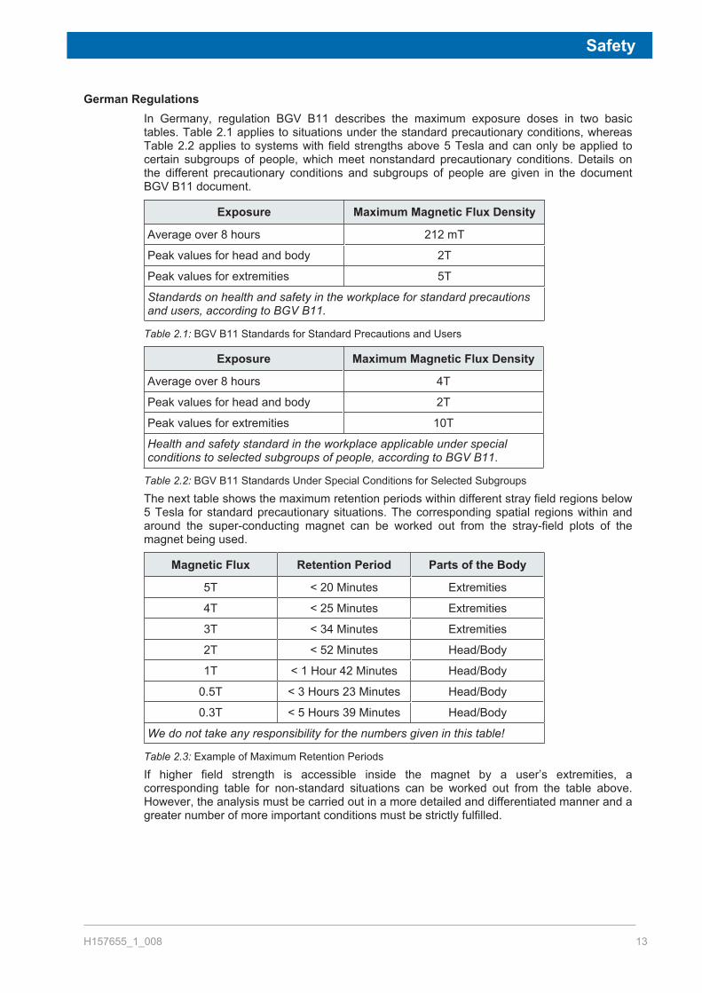
German RegulationsIn Germany, regulation BGV B11 describes the maximum exposure doses in two basictables. Table 2.1 applies to situations under the standard precautionary conditions, whereasTable 2.2 applies to systems with field strengths above 5 Tesla and can only be applied tocertain subgroups of people, which meet nonstandard precautionary conditions. Details onthe different precautionary conditions and subgroups of people are given in the documentBGV B11 document.
Exposure Maximum Magnetic Flux Density
Average over 8 hours 212 mT
Peak values for head and body 2T
Peak values for extremities 5T
Standards on health and safety in the workplace for standard precautionsand users, according to BGV B11.
Table 2.1: BGV B11 Standards for Standard Precautions and Users
Exposure Maximum Magnetic Flux Density
Average over 8 hours 4T
Peak values for head and body 2T
Peak values for extremities 10T
Health and safety standard in the workplace applicable under specialconditions to selected subgroups of people, according to BGV B11.
Table 2.2: BGV B11 Standards Under Special Conditions for Selected Subgroups
The next table shows the maximum retention periods within different stray field regions below5 Tesla for standard precautionary situations. The corresponding spatial regions within andaround the super-conducting magnet can be worked out from the stray-field plots of themagnet being used.
Magnetic Flux Retention Period Parts of the Body
5T < 20 Minutes Extremities
4T < 25 Minutes Extremities
3T < 34 Minutes Extremities
2T < 52 Minutes Head/Body
1T < 1 Hour 42 Minutes Head/Body
0.5T < 3 Hours 23 Minutes Head/Body
0.3T < 5 Hours 39 Minutes Head/Body
We do not take any responsibility for the numbers given in this table!
Table 2.3: Example of Maximum Retention Periods
If higher field strength is accessible inside the magnet by a user’s extremities, acorresponding table for non-standard situations can be worked out from the table above.However, the analysis must be carried out in a more detailed and differentiated manner and agreater number of more important conditions must be strictly fulfilled.

Safety
14 H157655_1_008
2.3 VentilationTypical NMR superconducting magnets use liquid cryogens as cooling agents. During normaloperation of the magnet system it can be expected that a boil-off will occur:
• A normal boil-off of liquids contained in the magnet will occur based on the establishedboil-off specifications.
• A boil-off of cryogens will occur during regular refills.A very large increase in volume accompanies vaporization of the cryogenic liquids into gas.The cryogenic gas to liquid volume ratio for helium is 740:1. Due to this large increase involume the vapor may displace the air in an enclosed room. If someone is in the room, thismay lead to asphyxiation. To prevent this and other dangers, the following minimum generalsafety rules concerning ventilation apply:
• Cryogenic liquids, even when kept in insulated storage dewars, remain at a constanttemperature by their respective boiling points and will gradually evaporate. These dewarsmust always be allowed to vent or dangerous pressure buildup will occur.
• Cryogenic liquids must be handled and stored in well ventilated areas.• Exit doors must open to the outside, to allow safe exit in the event the room becomes
pressurized by helium gas during a magnet quench.• Room layout, ceiling clearance and magnet height must be such that an easy transfer of
liquid nitrogen and helium is possible. This will considerably reduce the risk of accidents.
2.3.1 Regular Ventilation
Regular HVAC systems should be able to handle 3 - 5 room air exchanges per hour, andprovide temperature stability of +/- 1°C per 24 hours for 300-500 MHz systems, and +/- 0.5°Cper 24 hours for 600 MHz and above,. Please refer to HVAC (Heating Ventilation AirConditioning) [} 65] for more details.
2.3.2 Emergency Ventilation
Depending on the actual size of the magnet room, a large amount of He and/or N2 gas coulddisplace the air in the room. This is possible during the initial cooling of the magnet, duringfollow-up cryogen fills, or in case of a quench. Therefore, an emergency exhaust system maybe required to avoid asphyxiation. Please refer to the section Emergency Ventilation DuringInstallation and Quenches [} 68], for more details.
PitsAs discussed in HVAC (Heating Ventilation Air Conditioning) [} 65], continuous air flow(exhaust) is required within the confines of a magnet pit. A low exhaust down in the pit isrecommended. Additional emergency ventilation may also be necessary. Since nitrogen gascannot be detected by the human senses, an oxygen sensor mounted in the pit will trigger anincreased rate of exhaust.

Safety
H157655_1_008 15
2.3.3 Oxygen Level Sensors
Oxygen (O2) monitors, or level sensors, are required in the magnet room to detect low levelsof O2 due to cryogenic gases. At a minimum the following sensors must be provided:
• One oxygen level sensor must be above the magnet, to detect low oxygen levels causedby high helium gas levels.
• One oxygen level sensor approx. 30 cm off the floor of the magnet room.• One additional oxygen level sensor approx. 30 cm off the bottom of the pit, in case the
magnet is located inside a pit.These monitors and sensors generally must be located outside the 0.5 mT (5 G) line. Checkwith original equipment manufacturer for information on the effects of magnet fields on thesedevices.Please refer to Emergency Ventilation During Installation and Quenches [} 68] for moreinformation on ventilation and exhaust solutions.
2.4 Safe Handling of Cryogenic SubstancesSuperconducting NMR magnets use liquid helium (all magnets) and nitrogen (only non-Aeonmagnets) as cooling agents, keeping the magnet core at a very low temperature. The safehandling of cryogenic liquids requires some knowledge of the physical properties of theseliquids, common sense, and sufficient understanding to predict the reactions of such liquidsunder certain physical conditions.Cryogenic liquids, even when kept in insulated storage vessels (dewars), remain at aconstant temperature by their respective boiling temperature. As a result, a fraction of theliquid constantly evaporates into the gas phase, leading to a pressure build-up inside thestorage dewar. A very important characteristic of cryogens is their enormous increase involume during the conversion from liquid to gaseous phase. This conversion follows a raise ingas temperature starting at the boiling temperatures of the cryogenic liquids and going uptowards room temperature.The gases are nontoxic and completely harmless as long as adequate ventilation is providedto avoid suffocation. During normal operation only a small hourly rate of cryogen isevaporated, but during a quench, an extremely large quantity of helium gas is producedwithin a short time.Cryogenic liquids must be handled and stored in well ventilated areas. Containers forcryogenic liquids must be constructed with non-magnetic materials and should be specificallydesigned for use with particular cryogens. Be sure to read and follow any specific instructionsprovided by the container manufacturer concerning their individual products.
2.4.1 What is a Quench
A magnet quench is the breakdown of superconductivity in a partially or fully energizedmagnet. The stored field energy is transformed into heat, leading to a fast evaporation ofliquid helium. During a quench, an extremely large quantity of helium gas is produced within ashort time.Although helium gas is inert, if generated in large enough quantities, it can displace theoxygen in the room causing potential danger of suffocation (refer to Emergency VentilationDuring Installation and Quenches [} 68]).

Safety
16 H157655_1_008
2.4.2 Liquid Helium Refills
Liquid helium is the coldest of all cryogenic liquids, therefore it will condense and solidify anyother gas (air) coming in contact with it. The consequent danger is that pipes and vents maybecome blocked with frozen gas. Vacuum insulated pipes should be used for transferringliquid helium.Liquid helium must be kept in specially designed storage or transport dewars. A one-wayvalve is supplied to avoid air or moisture from entering the helium vessel. This is to preventice from building and plugging the neck tubes. The 0.2 bar valve must be mounted at alltimes even during a helium transfer.Often, permanently installed helium gas lines are used to pressurize the liquid heliumtransport dewars during the helium refills. Alternatively, helium gas cylinders can be used.The helium gas cylinder should never be brought close to the magnet and should always bekept well outside the 5 Gauss line. The gas cylinder should be secured to a wall or structuralcolumn well outside the 5 Gauss line to prevent a dangerous accident. A He gas purity of 4.6(99.996%) is recommended.With the Aeon magnet, helium fills are typically needed only during the magnet installation.Helium refills are not required during the normal operation given that there is no helium loss.Helium top-offs or refills are to be done by Bruker engineers, these are needed duringcryocooler and helium compressor services and in case of power or cooling water failures ifno back-up utilities are present.
2.5 Earthquake SafetyIn regions where there is a potential risk of earthquakes, additional precautions should betaken to reduce the chance of personal injury or property damage through movement ortipping of the magnet.Many countries or regions have documented regulations, including building codes, regardingearthquakes. Before installing a magnet system, it is highly advisable that you check withlocal authorities on whether your area is prone to earthquakes and if there are anyregulations in effect.If the installation site is regarded as an earthquake area, please contact Bruker forinformation on earthquake securing equipment.

Safety
H157655_1_008 17
2.6 Safety from Nearby ConstructionIn a magnet system hazards come basically from two sources:
• Mechanical breakdown of the mounting suspension in the magnet system.• Quench as a result of mechanical movement of the superconductor and as a result the
magnet reaching a critical temperature.
No permanent damage results from the mechanical movement of the superconductor,however when the suspension is damaged, it must be repaired.These amplitudes are mainly in the vertical direction. For permanent faults we give amaximum peak value of 0.01 g (0.981 m/s2) for systems with activated ADI or API dampers.Undamped systems can be operated up to a maximum of 1 mg or 9.81 mm/s2. NMRmeasurements are not possible in these vibration entries.For short term accelerations, which can occur during earthquakes, we have experienced thatthe NMR magnet systems survive a strength of 6.0 or accelerations up to 0.2 g > 90%.
2.7 Country-Specific Safety RegulationsIn addition to the above safety precautions, any country-specific safety regulations foroperating NMR systems must be fulfilled. These may include, for example, regulations on:
• Facilities of a controlled access area around the magnet• Working conditions at computer stations• Use of anesthesia gases• Handling of laboratory and transgenic animals
2.8 Emergency PlanningDue to the strong magnetic fields and presence of cryogens when using NMR systems, it isimportant to define and communicate what to do in case of problems or an emergency. An Emergency Plan can be defined as a documented set of instructions on what to do ifsomething goes wrong. Emergency Plans are often defined as part of the Standard OperatingProcedures (SOP), or as a stand-alone document. In any case every NMR laboratory shouldhave an Emergency Plan in effect.As every organization has its own policies and procedures, as well as varying laboratorylayouts, an Emergency Plan should be individually defined by the customer for theirlaboratory as appropriate. The Emergency Plan is the responsibility of the customer and ofthe building and facility management.

Safety
18 H157655_1_008
2.8.1 Fire Department Notification
It is recommended that the magnet operator introduce the fire department and/or localauthorities to the magnet site. It is important that these organizations be informed of thepotential risks of the magnet system, e.g. that much of the magnetic rescue equipment(oxygen-cylinders, fire extinguishers, axe's etc.) can be hazardous close to the magnetsystem. In addition, their expertise and experience can be invaluable in creating anEmergency plan.
• In a NMR laboratory use only non-magnetic fire extinguishers.• Breathing equipment which uses oxygen tanks made out of magnetic material can be life
threatening when used close to a magnet system which is energized.• During a quench helium gas escaping from the system must not be mistaken for smoke.
Instruct the fire department and technical service not to „extinguish“ the magnet systemwith water. The outlet valves could freeze over the quench valves eventually do not closeagain.
• Laboratory windows which are accessible during an emergency must be clearly markedwith warning signs, visible from the outside.

System Components
H157655_1_008 19
3 System ComponentsThis section describes the types and functions of the various sub-systems that are deliveredas part of our AVANCE UltraStabilized NMR systems. These include the following:
• Superconducting Magnet Components [} 19].• Console and Other System Components [} 20].• CryoProbe System (Optional) [} 21].• Other Optional Components [} 23].
3.1 Superconducting Magnet ComponentsThe superconducting magnet is a complex system producing a very strong, homogeneous,and stable magnetic field as required for NMR. This section describes the various sub-systems of the magnet system.
Magnet: The magnet system’s main component is a superconducting coil housedin a cryostat. The cryostat consists of an outer vacuum enclosure, someradiation shields and a liquid helium vessel.The magnet uses liquid helium as cryogenic liquid. The magnet coil isimmersed in a sub-cooled liquid helium (~2 K) bath. An additional liquidhelium bath operating at a standard temperature of 4.2 K is locatedabove the sub-cooled helium section and is also housed in the outervacuum enclosure.After the initial charging with electrical current, the magnet runs inpersistent mode. The current runs in a closed loop inside the system andthe magnet itself is no longer connected to a continuous power supply.
Pulse TubeCooler:
The magnet system is equipped with one cryocooler (pulse tube type).The cold head is mounted on top of the magnet. The rotary valve ismounted on a column right next to the magnet.The cryocooler re-liquefies helium that has been extracted by pumpingand virtually leads to cryogen consumption free operation.
HeliumCompressor:
An oil-lubricated helium compressor is used to supply pressurized heliumgas for PTC operation. This compressor requires water cooling andelectrical power without any interruption.
Maintenance: Magnet maintenance consists of refilling the system with cryogenic fluidsat defined time intervals.

System Components
20 H157655_1_008
3.2 Console and Other System ComponentsThe next table lists the various parts of the console, monitoring & control units. Please alsorefer to the floor plan diagrams beginning in the chapter Floor Plan [} 73]. These scaleddiagrams provide an idea of where the various pieces of NMR equipment should be placed.
1 2 3
4 5 6Figure 3.1: Spectrometer and Magnet Control
1. The AVANCE console main cabinet, where the actual NMR data acquisition isperformed.
2. The probe, which is designed to hold the sample, transmit radio frequency signalswhich excite the sample and receive the emitted response. The probe is insertedinto the bottom of the magnet and sits inside the room temperature shims. Coaxialcables carry the excitation signals from the console amplifiers to the probe andthe NMR signal back from the sample to the receiver.
3. The HPPR/2 amplifies, filters and routes the NMR response signals from theprobe to the RX22 receiver. It switches the RF transmitter output to the probe.
4. The BCU-II Unit delivers very cold gas, either nitrogen or dry air, through aflexible isolated non-magnetic transfer line. It is possible to control the sampletemperature down to -60°C inside the probe for solid or liquid NMR applications.
5. The BCU-I Unit cools VT gas to allow proper sample temperature regulation. Theunit reduces the temperature of the air input (supplied by the variable-temperatureunit) and provides cooling of the NMR sample within the magnet to at least -5 °Cfor a room temperature of 25 °C.
6. The workstation acts as the operational computer for the user processing NMRdata and sending/receiving data to/from the acquisition computer in the mainconsole.

System Components
H157655_1_008 21
3.3 CryoProbe System (Optional)The Bruker CryoProbeTM Accessory for the AVANCE NMR spectrometers offers dramaticincreases in signal to noise ratio, stability, and ease of use. For site planning details for theCryoProbe accessory, refer to CryoProbe and Other Accessories [} 83].The CryoProbe system consists of the following components:
3 4 5
1 2
Figure 3.2: CryoProbe System
1. The CryoProbe represents the NMR probe inside the magnet bore, and is cooledby cryogenic helium gas. The CryoProbe maximizes efficiency and reducesthermal noise, thus enhancing the signal-to-noise ratio.
2. The CryoCooling unit contains a cryocooler, a cryocontroller, a vacuum system,and He transfer lines. The unit cools compressed helium gas by expansion andprovides and maintains the vacuum insulation. The unit also supervises allCryoProbe operations.
3. The research grade Helium gas cylinder provides research grade helium gas(99.9999%) at high pressure (min. 200 bar) for flushing the probe prior to a cool-down cycle. The cylinder includes a regulator, an outlet valve, and a charginghose.
4. A transfer line supports provide support for the probe and isolates the probeagainst vibrations.
5. The He compressor provides compressed helium gas to the CryoCooling unit.The compressor connects to the CryoCooling unit by means of helium gaspressure lines. The indoor water-cooled helium compressor is shown to the right.Other models, including indoor air-cooled and outdoor air-cooled, are available.

System Components
22 H157655_1_008
3.4 CryoProbe Prodigy System (Optional)The CryoProbe Prodigy is a new CryoProbe generation designed specifically for AVANCE IIIspectrometers. Costing significantly less than a conventional CryoProbe, the broadbandCryoProbe Prodigy uses nitrogen-cooled RF coils and preamplifiers to deliver a sensitivityenhancement over room temperature (RT) probes of a factor of 2 to 3 for X-nuclei from 15N to31P. The Prodigy package is comprised of the probe, a control unit (PCU) and a liquidnitrogen vessel, thus siting is easy and no additional infrastructure is required.
Figure 3.3: CryoProbe Prodigy with Pump & Control Unit and LM2 Tank

System Components
H157655_1_008 23
3.5 Other Optional Components
1 2
3 4Figure 3.4: Other Options for AVANCE Systems
1. SampleCase is a 24 sample, random-access, automation system that fits almostall shielded Bruker standard bore magnets.
2. SampleJet is a robot which has been consciously designed to meet growingdemand for simplicity, versatility and higher throughput in NMR sample tubeautomation.
3. SampleXpress allows automatic measurement of NMR samples with BrukerNMR spectrometers. SampleXpress is controlled by TopSpin or IconNMR, and isequipped with integrated barcode reader registration, which is under control ofSampleTrack.
4. The imaging accessory cabinet houses the gradient amplifiers for micro-imaging applications.
5. An optional UPS (not shown) is highly recommended and may vary based onthe system configuration.

System Components
24 H157655_1_008
Magnet Access and Rigging
H157655_1_008 25
4 Magnet Access and RiggingThe magnet is very heavy and fragile, thus requires special consideration during delivery andmovement to its final installation point. The other components of the spectrometer system(console, options, etc.) can typically be removed from the trucks with forklifts and arepositioned in the NMR lab with a pallet jack. Specifications for these components are alsoincluded in this chapter for planning purposes.
4.1 Considerations for Off-loading on SiteWhen planning for offloading the magnet and console during delivery, the following factorsmust be considered:
Delivery AreaThere must be sufficient space in the driveway or parking area for the overhead crane (orforklift) and for the delivery truck. There must also be sufficient leveled area for uncrating themagnet and other crates.
Transport WeightThe transport weight and size of the magnet system, console and their respective crates willaffect the choice of equipment required for offloading and movement of the magnet.
Loading DockThe size and overhead clearance of the loading dock will influence the choice of forklift,crane, or other rigging equipment required to off load the magnet and system crates.The elevation of the loading dock relative to the laboratory will determine if a crane isrequired, or if an elevator is needed for the transportation of the magnet from the loadingdock to the laboratory.The load bearing capacity of the loading dock must be sufficient for the system. Refer to thetransport weights of the magnet system, console, and accessories listed in the chapter.If height/width restrictions require the magnet to be removed from the pallet (e.g. to passthrough a doorway), rigging equipment will be needed both on the loading dock and insidethe lab.
Equipment RequirementsAll rigging equipment required to off-load the magnet system must be selected to handle thesize and transport weights of the system.Generally a pallet is integrated in the magnet crate. The top and sides of the crate areremoved or lifted off the magnet, leaving the pallet under the magnet for transportation intothe lab.Crane: For larger magnet systems, a crane meeting the load requirements for the specificmagnet may be required to lift the magnet off the truck, place it on a flat surface for uncrating,and for lifting the magnet again for placement on air skates or a pallet.Forklift: It may be feasible to use a forklift to pick the magnet from the truck and lower it to aflat surface for uncrating.Pallet Jack: If a loading dock is available, it may be possible to roll the magnet off the truckusing a pallet jack.

Magnet Access and Rigging
26 H157655_1_008
4.2 Considerations for Transport to the NMR laboratoryBefore delivery the customer must ensure that the system and magnet can be transported tothe site. The section on Transport Dimensions and Weights [} 26] in this chapter providesthe sizes and weights of the crates in which the system are shipped. The following must beconsidered:
• The access clearance (height and width) and floor loading capacity must be checkedalong the entire route that the magnet will take from the access point into the building tothe laboratory. Please refer to the Transport Dimensions and Transport Weights tables.
• Transport will also be affected by any floor irregularities and the presence of door jamsand steps. Use Masonite leveling sheets to traverse floor irregularities such as cracksand door seals.
• Elevator capacity and dimensions must also be considered if the magnet must make anelevation change within the building.
• The turning radius can also be a factor if, for example, corners must be navigated. It isimportant to make sure the rigging equipment for magnet assembly (e.g. a long I-beam forthe gantry) can be brought into the lab.
• The console and magnet must be moved in an upright position.
Refer to the section Rigging Equipment [} 31] for more information.
4.3 Transport Dimensions and Weights
4.3.1 Magnet Transport Dimensions
Door Dimensions for Magnet Access
Crate Size (m) Magnet Transport Dimensions (m)(for transport to the magnet room)
Magnet Type(MHz/mm)
L D H WidthUncrated
HeightUncrated w/
o PalletJack*
HeightUncrated
with PalletJack**
400/54 Ascend Aeon 1.34 1.14 1.98 0.85 1.53 1.64
500/54 Ascend Aeon 1.34 1.14 1.98 0.85 1.53 1.64
600/54 Ascend Aeon 1.15 1.36 2.02 0.95 1.74 1.85
700/54 Ascend Aeon 1.15 1.36 2.02 0.95 1.74 1.85
* Measured from magnet bottom plate to helium tower - this is the absolute minimumheight!** The heights listed with pallet jack assume that the floor is level, thus the magnet needsonly to be jacked up approx. 2 cm for transport. If the floor is uneven, the magnet mayneed to be jacked up accordingly, which could add as much as 9 cm to the transportheight.
Table 4.1: Door Dimensions: Standard Bore 54 mm

Magnet Access and Rigging
H157655_1_008 27
Crate Size (m) Magnet Transport Dimensions (m)(for transport to the magnet room)
System(MHz/mm)
L D H WidthUncrated
HeightUncrated w/
o PalletJack*
HeightUncrated
with PalletJack**
400/89 Ascend Aeon 1.15 1.35 2.08 0.85 1.53 1.64
500/89 Ascend Aeon 1.15 1.36 2.02 0.95 1.74 1.85
600/89 Ascend Aeon 1.15 1.35 2.08 0.85 1.53 1.64
700/89 Ascend Aeon 1.50 1.30 2.14 0.85 1.53 1.64
* Measured from magnet bottom plate to helium tower - this is the absolute minimumheight!** The heights listed with pallet jack assume that the floor is level, thus the magnet needsonly to be jacked up approx. 2 cm for transport. If the floor is uneven, the magnet mayneed to be jacked up accordingly, which could add as much as 9 cm to the transportheight.
Table 4.2: Door Dimensions: Wide Bore 89 mm
4.3.2 Magnet Stand Transport Dimensions
Door Dimensions for Magnet Stand & Accessories Access
Accessories Crate Size - including stand ifapplicable (m)
Magnet Stand L D H
400/54 Ascend Aeon F85 570 ADI 0.97 0.76 1.20
400/54 Ascend Aeon F85 700 ADI 0.97 0.76 1.20
400/54 Ascend Aeon F85 570 API 0.97 0.76 1.20
400/54 Ascend Aeon F85 700 API 0.97 0.76 1.20
500/54 Ascend Aeon F85 570 ADI 0.97 0.76 1.20
500/54 Ascend Aeon F85 700 ADI 0.97 0.76 1.20
500/54 Ascend Aeon F85 570 API 0.97 0.76 1.20
500/54 Ascend Aeon F85 700 API 0.97 0.76 1.20
600/54 Ascend Aeon F95 700 API 1.77 0.97 1.11
700/54 Ascend Aeon F95 700 API 1.77 0.97 1.11
Pallet is integrated in crate. Add 2-10 cm for pallet jack depending on floor quality. Allowat least 1 cm clearance on the sides and above the crate.
Table 4.3: Door Dimensions for Magnet Stand: Standard Bore 54 mm

Magnet Access and Rigging
28 H157655_1_008
Accessories Crate Size - including stand ifapplicable (m)
Magnet Stand L D H
400/89 Ascend Aeon F95 950 API 1.32 0.74 1.29
500/89 Ascend Aeon F95 950 API 1.32 0.74 1.29
600/89 Ascend Aeon F95 950 API 1.32 0.74 1.29
700/89 Ascend Aeon F110 950 API 1.32 0.74 1.29
Pallet is integrated in crate. Add 2-10 cm for pallet jack depending on floor quality. Allowat least 1 cm clearance on the sides and above the crate.
Table 4.4: Door Dimensions for Magnet Stand: Wide Bore 89 mm
4.3.3 Magnet Transport Weights
Magnet Type Magnet Weight withCrate (kg)
Magnet Weight w/oCrate & Stand (kg)
400/54 Ascend Aeon ~600 ~490
500/54 Ascend Aeon ~700 ~590
600/54 Ascend Aeon ~1000 ~850
700/54 Ascend Aeon ~1300 ~1150
The weights of the accessories are approximations. The actual weight may varydepending on the options and accessories that are ordered.
Table 4.5: Magnet Transport Weights: Standard Bore 54 mm
Magnet Type Magnet Weight withCrate (kg)
Magnet Weight w/oCrate & Stand (kg)
400/89 Ascend Aeon ~970 ~785
500/89 Ascend Aeon ~1050 ~865
600/89 Ascend Aeon ~1300 ~1120
700/89 Ascend Aeon ~1900 ~1740
The weights of the accessories are approximations. The actual weight may varydepending on the options and accessories that are ordered.
Table 4.6: Magnet Transport Weights: Wide Bore 89 mm

Magnet Access and Rigging
H157655_1_008 29
4.3.4 Spectrometer and Accessories Transport Dimensions and Weights
Crate Size (m) Weight Dimension (m) for Transport to MagnetRoom
Spectrometer System(spectrometer crate)
L D H (kg) WidthCrated*
WidthUncrated*
HeightUncrated
AVANCE TwoBay 1.54 1.03 1.54 210 1.05 0.82 1.67
AVANCE OneBay 1.00 0.92 1.53 210 1.02 0.71 1.66
AVANCE NanoBay 1.34 0.75 1.04 120 (withoutpallet andpackingmaterial)
0.77 0.45 0.93
Note: The pallet is now integrated into the crate. Weights include pallets and packing material asrequired. Weights are for a standard AVANCETM configuration, actual weights may increase dependingon options selected.* Transport width = width indicated + minimum 1 cm clearance on each side. These are the widths if theconsole is inserted lengthways through the entrance.
Table 4.7: Door Dimensions for Magnet Room Access: Spectrometers

Magnet Access and Rigging
30 H157655_1_008
Crate Size (m) Weight
Accessory L D H (kg)
LC-NMR Unit, LC-NMR Control Unit (hostcomputer), plus any additional options/accessories
n/a* n/a* n/a* 50-250
Imaging Cabinet n/a* n/a* n/a* 150
SampleXpress 0.96 0.96 0.52 48
SampleXpress Lite 0.57 0.69 0.42 22
SampleJet 1.20 0.80 1.20 100
SampleJet Cooling Option – Carousel Box 0.56 0.56 0.33 ~10
SampleCase box 1/box2 1.89/0.75 0.52/0.75 0.27/0.65 15/15
BCU-I 0.48 0.36 0.43 50
BCU-II 0.58 0.42 0.57 74
CryoProbe (shipped in a CryoCase on apallet)
1.20 0.80 0.68 60
CryoCooling Unit 1.66 0.95 0.68 400
CryoProbe System He Compressor IndoorWater-cooled
0.94 0.84 1.18 120
CryoProbe System He Compressor IndoorAir-cooled (packed in three cartons on onepallet)
0.69 0.69 1.12 140
CryoProbe System He Compressor OutdoorAir-cooled (packed in three cartons on onepallet)
0.55 0.55 0.90 140
CryoProbe Prodigy Unit 0.75 0.48 0.69 68
The accessories are typically transported to the magnet on a pallet jack. Weights include pallets andpacking material as required.* Not available at time of publication.
Table 4.8: Crate Dimensions and Weights for Accessories

Magnet Access and Rigging
H157655_1_008 31
4.4 Rigging EquipmentRigging equipment is not included with the NMR system order. The following riggingequipment will be needed for a typical delivery and installation of an NMR magnet system:
• Pallet Jack and/or Fork Lift: For transporting system magnet and accessories to thelaboratory.
• A-Frame or Lifting Hook: An A-Frame or lifting hook may be used inside the laboratoryduring assembly phase. When a lifting hook is used, the hook capacity must be certified tohold the required weight of the magnet before installation!
Figure 4.1: A-Frame Gantry for Lifting the Magnet Inside the Magnet Room

Magnet Access and Rigging
32 H157655_1_008

Ceiling Height Requirements
H157655_1_008 33
5 Ceiling Height RequirementsThe assembly of the magnet system, the magnet energization, and refills with liquid heliumrequire minimum height clearances.
• The ceiling height requirements for the magnet installation and cryogen refills do not needto be met over the entire laboratory. The height requirements need only be metimmediately above the magnet, over an area to allow for assembly of the lifting system (ifapplicable), and over an area to allow for insertion of the helium transfer line.
• If a soffit is to be used, it is important to consider the area of raised ceiling needed to set-up the lifting system being used to lift the magnet during the assembly phase of theinstallation. If a transverse I-beam is used in conjunction with the lifting system, this mustfit within the confines of the soffit.
• In lieu of a lifting system, a fixed lifting hook capable of supporting the magnet at asufficient height can be used to assemble the magnet. However, this option is usually notideal. See notes below.
WARNINGFixed HookDanger to personnel and equipment due to falling lifting system when using a fixed hook.Removing the heavy hoist directly over the magnet can be very difficult and dangerous forboth personnel and the magnet.u It is important to consider how the hoist system and harness will be removed from a
fixed lifting hook after the magnet is installed.u Ensure that the hook is certified to hold the weight of the equipment before use.

Ceiling Height Requirements
34 H157655_1_008
5.1 Helium Transfer Line
Figure 5.1: Ceiling Height Requirements
1. Ceiling height must allow for insertion of helium transfer lines.2. Liquid helium dewar.3. Ceiling height requirements must be met over this area.4. Magnet.
Ceiling Height Requirements
H157655_1_008 35
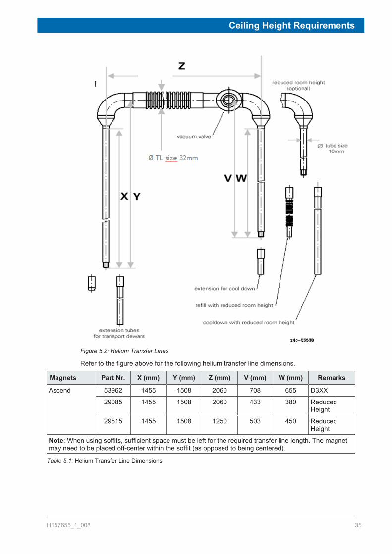
Figure 5.2: Helium Transfer Lines
Refer to the figure above for the following helium transfer line dimensions.
Magnets Part Nr. X (mm) Y (mm) Z (mm) V (mm) W (mm) Remarks
Ascend 53962 1455 1508 2060 708 655 D3XX
29085 1455 1508 2060 433 380 ReducedHeight
29515 1455 1508 1250 503 450 ReducedHeight
Note: When using soffits, sufficient space must be left for the required transfer line length. The magnetmay need to be placed off-center within the soffit (as opposed to being centered).
Table 5.1: Helium Transfer Line Dimensions

Ceiling Height Requirements
36 H157655_1_008
5.2 Minimum Ceiling HeightThe minimum ceiling height requirements for operation of each magnet are listed in thefollowing table. Note that the values represent the absolute minimum, an extra 0.3-0.4 mabove minimum requirements will make all procedures safer and more convenient.
Note: The minimum ceiling height requirements for INSTALLATION may be greater than thevalues in the table below, depending on the options selected.
Note: When calculating the minimum ceiling height, the height of the transport dewar plusthe long arm of the transfer line must be considered. Refer to the transport dewar supplier forheight specifications.
The following text explains how the ceiling height requirements in the ceiling heightrequirements table were either calculated and/or their meaning. Note that the values werecalculated for the smallest available magnet stand.
Minimum Operational CeilingHeight – Helium Transfer Line29085:
The minimum operational ceiling height using thehelium transfer line 29085 is calculated by adding theheight of the shim upper part that has to be insertedinto the cryostat, to the height of the top flange of thecryostat.
Minimum Ceiling Height withHelium Transfer Line 53962:
The ceiling height using the standard helium transferline 53962 is calculated by adding the height of theshim upper part that has to be inserted into the cryostat,to the height of the top flange of the cryostat.
Minimum Ceiling Height forAdapter WB -> SB:
For all wide bore systems, the minimum ceiling height iscalculated to the top of the upper part reduction adapterWB -> SB.

Ceiling Height Requirements
H157655_1_008 37
Ceiling Height RequirementsThe number in the following tables corresponds to a standard magnet configuration using aminimum height stand. The ceiling height can increase up to 250 mm based on the model ofthe magnet and stand. Refer to the table in Magnet Stand Transport Dimensions forspecification on the magnet model and stand.
Magnet Type Special LHE Transfer Linefor Reduced Ceiling
Height (m)
Standard LHE TransferLine (m)
400/54 Ascend Aeon 2.66 3.04
500/54 Ascend Aeon 2.66 3.04
600/54 Ascend Aeon 3.00 3.39
700/54 Ascend Aeon 3.00 3.39
Table 5.2: Minimum Ceiling Height Requirements: Standard Bore 54 mm
Magnet Type Special LHE Transfer Linefor Reduced Ceiling
Height (m)
Standard LHE TransferLine (m)
400/89 Ascend Aeon 3.25 3.64
500/89 Ascend Aeon 3.25 3.64
600/89 Ascend Aeon --- 3.65
700/89 Ascend Aeon 3.40 3.79
Table 5.3: Minimum Ceiling Height Requirements: Wide Bore 89 mm

Ceiling Height Requirements
38 H157655_1_008

Magnetic Stray Fields
H157655_1_008 39
6 Magnetic Stray FieldsMagnetic stray fields are three dimensional, and extend further in the vertical direction than inthe horizontal direction.A number of studies have been carried out on the long term effects of magnetic fields onpersonnel. As a general rule the working place (e.g. workstation, sample preparation areaetc.) must be placed outside the 0.5 mT (5 G) line. For further information on acceptablemagnetic field limits contact your countries health authorities or your area Bruker office.Various devices are affected by the magnet and must be located outside the limits specifiedin the following section. For comparison the earth’s magnetic field is 0.05 mT (0.5 G).
Please note that when more than one magnet is located in a room the 0.5 mT (5 G) line fromeach magnet should not overlap.
Stray FieldDistances
Device Effects
200 mT (2000 G) All devices should be outside this line. Refer to current standards onhealth and safety (e.g. BGV B11 in the European Community) in theworkplace for specifications on how long personnel may remain withinthis area.
5 mT (50 G) Magnet power supply, RFpower amplifier, Cryo-coolingplatform.
Electrical transformers which are acomponent of many electricaldevices may become magneticallysaturated in fields above 50 Gauss(5 mT). The safety characteristics ofequipment may also be affected.
2 mT (20 G) Magnetic storage material The information stored on tapes maybe destroyed or corrupted.
1 mT (10 G) Computers, X-ray tubes, creditcards, bank cards, watches,clocks, cameras, TFT computermonitor.
The magnetically stored informationin computers and credit cards maybe corrupted in fields greater than 1mT (10 G). Small mechanicaldevices such as watches or camerasmay be irreparably damaged.(Digital watches may be wornsafely).
0.5 mT (5 G) Pacemakers, MedicalImplants Cathode Ray tubes,CryoProbe compressor.
Magnetic fields greater than 0.5mT (5 G) will deflect a beam ofelectrons leading to a distortionof the screen display.
0.1 mT (1 G) Only very sensitive electronic equipment such as image intensifiers,nuclear cameras and electron microscopes will be affected.
Table 6.1: Effects of Magnetic Fields on Equipment
The accompanying tables in this chapter display the horizontal stray fields in the radial,direction, as well as, the vertical stray field in the axial direction.

Magnetic Stray Fields
40 H157655_1_008
Please note all measurements in the following tables are in meters!
6.1 Horizontal Stray Fields
Magnet Type 5.0 mT(50 G)
3.0 mT(30 G)
1.0 mT(10 G)
0.5 mT(5 G)
0.2 mT(2 G)
0.1 mT(1 G)
0.05 mT(0.5 G)
400/54 Ascend Aeon 0.38 0.41 0.46 0.50 0.65 0.83 1.08
500/54 Ascend Aeon 0.47 0.50 0.56 0.60 0.74 0.96 1.26
600/54 Ascend Aeon 0.52 0.56 0.62 0.70 0.92 1.18 1.55
700/54 Ascend Aeon 0.49 0.52 0.65 0.80 1.10 1.42 1.87
Distances are measured in radial direction from magnetic center.
Table 6.2: Horizontal Stray Fields: Standard Bore 54 mm
Magnet Type 5.0 mT(50 G)
3.0 mT(30 G)
1.0 mT(10 G)
0.5 mT(5 G)
0.2 mT(2 G)
0.1 mT(1 G)
0.05 mT(0.5 G)
400/89 Ascend Aeon 0.44 0.47. 0.55 0.60 0.69 0.82 1.03
500/89 Ascend Aeon 0.50 0.54 0.62 0.70 0.92 1.17 1.52
600/89 Ascend Aeon 0.60 0.64 0.76 0.85 1.07 1.33 1.71
700/89 Ascend Aeon 0.80 0.88 1.09 1.25 1.50 1.81 2.26
Distances are measured in radial direction from magnetic center.
Table 6.3: Horizontal Stray Fields: Wide Bore 89 mm

Magnetic Stray Fields
H157655_1_008 41
6.2 Vertical Stray Fields
Magnet Type 5.0 mT(50 G)
3.0 mT(30 G)
1.0 mT(10 G)
0.5 mT(5 G)
0.2 mT(2 G)
0.1 mT(1 G)
0.05 mT(0.5 G)
400/54 Ascend Aeon 0.64 0.70 0.87 1.00 1.24 1.47 1.77
500/54 Ascend Aeon 0.80 0.87 1.06 1.20 1.48 1.75 2.09
600/54 Ascend Aeon 0.90 0.99 1.21 1.40 1.71 2.03 2.45
700/54 Ascend Aeon 0.99 1.09 1.37 1.60 2.01 2.42 2.95
Distances are measured in axial direction from magnetic center.
Table 6.4: Vertical Stray Fields: Standard Bore 54 mm
Magnet Type 5.0 mT(50 G)
3.0 mT(30 G)
1.0 mT(10 G)
0.5 mT(5 G)
0.2 mT(2 G)
0.1 mT(1 G)
0.05 mT(0.5 G)
400/89 Ascend Aeon 0.79 0.86 1.05 1.20 1.45 1.70 2.02
500/89 Ascend Aeon 0.88 0.97 1.21 1.40 1.73 2.07 2.49
600/89 Ascend Aeon 1.02 1.12 1.38 1.60 1.97 2.34 2.81
700/89 Ascend Aeon 1.56 1.72 2.15 2.50 3.09 3.67 4.41
Distances are measured in axial direction from magnetic center.
Table 6.5: Vertical Stray Fields: Wide Bore 89 mm

Magnetic Stray Fields
42 H157655_1_008
6.3 Stray Field Plots
Figure 6.1: Example of a Stray Field Plot

Environment and Site Survey Measurement
H157655_1_008 43
7 Environment and Site SurveyMeasurementThis chapter covers the various site survey topics related to the NMR laboratory. Themeasurements and associated guidelines include:
• Vibrations• Magnetic Environment• Electromagnetic Interference: DC and AC EMF• RF Interference
Note: The results of measurements carried-out during a site survey only reflect the specificconditions that were present during the survey. Although these results are useful as areference, they would not be conclusive for the after-the-installation system performance ifone or more site conditions change. These changes may be related but not limited tosources of vibrations and electromagnetic field and RF interference like electro-mechanicalequipment (HVAC, motors, pumps, freezers, etc.), elevators, car/bus/train traffic, powerlines, transformers, radio/TV stations and other possible RF sources.
7.1 VibrationsExternal vibrations may cause field modulations in the sample cavity. This could result invibration sidebands, matched NMR signals that appear on either side of a main signal peak.The effect of vibrations on NMR performance will depend on the type of work being carriedout, the type of system and the site building materials.
• Ideally the site should be at basement level, or on the ground floor (slap on grade), tominimize building vibrations.
• Possible sources of vibrations are generators, compressors, fans, machinery etc.Vibrations from external sources such as cars, trains, airplanes, and construction sites canalso cause problems.
• Measuring the extent of vibrations at the magnet location is a relatively simple matter; ifyou suspect a problem you should contact your local Bruker office.
The following thresholds represent the maximum velocities and accelerations that could betolerated on the floor of the laboratory where the magnet is going to be located.
Environment and Site Survey Measurement
44 H157655_1_008
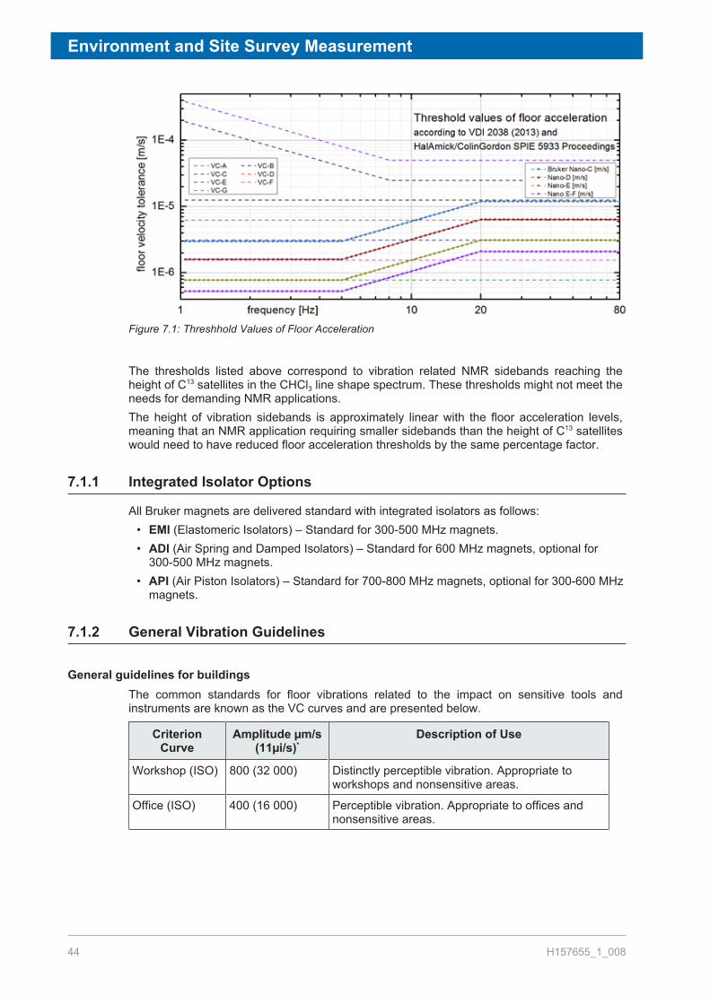
Figure 7.1: Threshhold Values of Floor Acceleration
The thresholds listed above correspond to vibration related NMR sidebands reaching theheight of C13 satellites in the CHCl3 line shape spectrum. These thresholds might not meet theneeds for demanding NMR applications.The height of vibration sidebands is approximately linear with the floor acceleration levels,meaning that an NMR application requiring smaller sidebands than the height of C13 satelliteswould need to have reduced floor acceleration thresholds by the same percentage factor.
7.1.1 Integrated Isolator Options
All Bruker magnets are delivered standard with integrated isolators as follows:• EMI (Elastomeric Isolators) – Standard for 300-500 MHz magnets.• ADI (Air Spring and Damped Isolators) – Standard for 600 MHz magnets, optional for
300-500 MHz magnets.• API (Air Piston Isolators) – Standard for 700-800 MHz magnets, optional for 300-600 MHz
magnets.
7.1.2 General Vibration Guidelines
General guidelines for buildingsThe common standards for floor vibrations related to the impact on sensitive tools andinstruments are known as the VC curves and are presented below.
CriterionCurve
Amplitude µm/s(11µi/s)*
Description of Use
Workshop (ISO) 800 (32 000) Distinctly perceptible vibration. Appropriate toworkshops and nonsensitive areas.
Office (ISO) 400 (16 000) Perceptible vibration. Appropriate to offices andnonsensitive areas.

Environment and Site Survey Measurement
H157655_1_008 45
CriterionCurve
Amplitude µm/s(11µi/s)*
Description of Use
Residential day(ISO)
200 (8 000)
Barely perceptible vibration. Appropriate to sleepareas in most instances. Usually adequate forcomputer equipment, hospital recovery rooms.semiconductor probe test equipment, andmicroscopes less than 40x.
Operatingtheater (ISO)
100 (4 000)Vibration not perceptible. Suitable in mostinstances for surgical suites, microscopes to 100xand for other equipment of low sensitivity.
VC-A 50 (2 000)Adequate in most instances for optical microscopesto 400x, microbalances, optical balances, proximityand projection aligners, etc.
VC-B 25 (1 000)Appropriate for inspection and lithographyequipment (including steppers) to 311m line widths.
VC-C 12.5 (500)
Appropriate standard for optical microscopes to1000x, lithography and inspection equipment(including moderately sensitive electronmicroscopes) to 1 11m detail size, TFT-LCDstepper/scanner processes.
VC-D 6.25 (250)Suitable in most instances for demandingequipment, including many electron microscopes(SEMs and TEMs) and E-Beam systems.
VC-E 3.12 (125)
A challenging criterion to achieve. Assumed to beadequate for the most demanding of sensitivesystems including long path, laser- based, smalltarget systems, E-Beam lithography systemsworking at nanometer scales, and other systemsrequiring extraordinary dynamic stability.
VC-F 1.56 (62.5)
Appropriate for extremely quiet research spaces;generally difficult to achieve in most instances,especially cleanrooms. Not recommended for useas a design criterion, only for evaluation.
VC-G 0.78 (31.3)
Appropriate for extremely quiet research spaces;generally difficult to achieve in most instances,especially cleanrooms. Not recommended for useas a design criterion, only for evaluation.
*As measured in one-third octave bands of frequency over the frequency range 8 to 80Hz (VC-A and VC-B) or 1 to 80 Hz (VC-C through VC-G).The information given in this table is for guidance only. In most instances, it isrecommended that the advice of someone knowledgeable about applications andvibration requirements of the equipment and processes be sought.Source: Reprinted with permission from Colin Gordan Associates.
Table 7.1: Application and Interpretation of the Generic Vibration Criterion (VC) Curves

Environment and Site Survey Measurement
46 H157655_1_008
7.1.3 Measuring Floor Vibrations
Bruker offers a service for measuring floor vibrations using specialized hardware andsoftware. We recommend measurements to be done over a period of at least 1 hour (ideallymuch longer) to try capturing both steady state conditions and transient events.Furthermore, we recommend a measurement resolution of <= to 0.125 Hz, enabling thecollection of correct amplitudes in the low frequency range.Also we recommend simultaneous measurements (multiple transducers) along the 3 axis(vertical, 2 horizontal).
7.1.4 Bruker NMR Floor Vibration Guidelines
EMI damping system (Elastomeric Isolators)
Figure 7.2: Threshold Values of Floor Acceleration: Tolerance Level for EMI Dampers
Frequency Maximum Velocity inVertical Direction
Maximum Velocity inHorizontal Direction
1-10 Hz 1.6…0.64 µm/s 1.6…0.64 µm/s
10-20 Hz 0.64…6.4 µm/s 0.64…6.4 µms
>20 Hz 6.4 µm/s 6.4 µm/s
Table 7.2: EMI Damping System (Elastomeric Isolators)

Environment and Site Survey Measurement
H157655_1_008 47
Figure 7.3: Example of the Bruker Tolerance Level for Elastomer Dampers. Resolution <0.125 Hz, 1…200 Hz, > 30 min, Average Measurement 1 (displayed in velocity)
Figure 7.4: Elastomer Dampers

Environment and Site Survey Measurement
48 H157655_1_008
7.1.5 Floor Vibration Guidelines: Bruker Nano-C and Nano-D
ADI damping system (Air Spring Damped Isolators with vertical damping)
Frequency Maximum Velocity inVertical Direction
Maximum Velocity inHorizontal Direction
1-5 Hz 3 µm/s 1.6 µm/s
5-20 Hz 3…12 µm/s 1.6…6.4 µms
>20 Hz 12 µm/s 6.4 µm/s
Table 7.3: ADI Damping System (Elastomeric Isolators)
Figure 7.5: Example of the Bruker Tolerance Level for ADI Dampers. Resolution <0.125 Hz, 1…200 Hz,> 30 min, Average Measurement 1 (displayed in velocity)

Environment and Site Survey Measurement
H157655_1_008 49
Figure 7.6: ADI Dampers
7.1.6 Floor Vibration Guidelines: Bruker Nano-C API Damping System
API Damping System
Figure 7.7: Tolerance Level Nano-C for API Dampers

Environment and Site Survey Measurement
50 H157655_1_008
Frequency Maximum Velocity inVertical Direction
Maximum Velocity inHorizontal Direction
1-5 Hz 3 µm/s 3 µm/s
5-20 Hz 3…12 µm/s 3…12 µms
>20 Hz 12 µm/s 12 µm/s
Table 7.4: Tolerance Level for API Damping System
Figure 7.8: Example of the Bruker Tolerance Level for API Dampers. Resolution <0.125 Hz, 1…200Hz,> 30 min, Average Spectra Measurement 1 (displayed in velocity)
According to VDI 2038 (2013) Bruker is following the threshold values of sensitive laboratoryequipment. Bruker implemented a Nano-C limit which is less critical as Nano-D. The only bigdifference in observing these data is to use a higher resolution as only 1/3 octave. Werecommend to measure with a resolution of < 0.125 Hz to get the right amplitudes in the lowfrequency part (average spectra over a period of > 30 min).
Figure 7.9: Schematic Drawing of an API Type Damping System

Environment and Site Survey Measurement
H157655_1_008 51
7.2 Magnetic EnvironmentThe presence of any ferromagnetic materials in the immediate vicinity of the magnet willdecrease the magnets homogeneity and may degrade overall performance. Althoughminimum requirements for routine NMR are not stringent, the magnetic environment must beoptimized if more sophisticated experiments are being carried out. Usually, the effect of metalpipes, radiators, and other such objects can be “shimmed out”, but whenever possible, thisshould be avoided.
7.2.1 Guidelines for Static Objects
The next table gives a list of common sources of magnetic interference for magnets. Theseitems should be located according to the recommendations below. It must be emphasizedhowever, that such recommendations represent a situation that may not be achievable.Please consult with Bruker for possible solutions if one or more of these recommendationscannot be satisfied.
Object Minimum distance from magnetic center (m)
Steel reinforced walls 2
Radiators, plumbing pipes 2
Metal table, metal door 2.5
Filing cabinet, steel cabinet 2.5
Iron or steel beams 3
Massive objects, e.g. boiler 3
Table 7.5: Guidelines for Static Magnetic Objects
7.2.2 Guidelines for Moving Objects
The table below serves as a guideline for moveable magnetic material.
Object Actual distance from magnetic center (m)
Steel cabinet doors 3
Large metal door, hand trolley 4
Elevators* 6
Trucks, cars, fork-lifts 9
Trains, subways, trams* 30
*Elevators, trains and trams are more likely to be a source of vibrational interference.Note that D.C. operated elevators, trains, and trams may cause disturbances over muchlarger distances (see Guidelines for DC Interference [} 53]).
Table 7.6: Guidelines for Moveable Magnetic Objects

Environment and Site Survey Measurement
52 H157655_1_008
7.3 Electromagnetic InterferencePossible sources of interference are power lines which may carry fluctuating loads, heavyduty transformers, large electric motors, air conditioning systems, power transformers, etc.The fluctuating electromagnetic fields arising from such devices can interfere with the magnetand cause spatiotemporal field instabilities. Of particular concern are sudden changes in loadas may be produced by elevators, trams, subways etc.Other sources of interference include radio and television stations, satellites and other HFtransmitters that may operate in the vicinity of NMR frequencies of interest.The effect of such interferences on the NMR/MRI/micro-imaging results strongly depends onvarious parameters, such as the experiment itself, digital lock parameters, lock substance,experiments (pulse programs), 2H S/N, magnet generation and temperature and if there is adigital lock at all.If you suspect that you have a source of interference located near the proposed magnet sitethen you should contact Bruker BioSpin for a site survey.Bruker offers a service for measuring EMF interferences using specialized hardware andsoftware. We recommend measurements to be done over a period of at least one hour(ideally much longer) to try capturing both steady state conditions and transient events.However, often there is a need to do much longer measurements, including overnight.
7.3.1 Types of EMF Interference
• DC interference (up to 1 Hz).• AC interference (from 1 Hz up to 200 Hz, especially 16 2/3 Hz*, 50 Hz, 60 Hz and
harmonics).• HF Interference.
* 16 2/3 is the standard for long distance train power lines.
7.3.2 DC EMF Interference
DC interferences (0-1 Hz) generally come from devices operated on DC, such as subways,trams, trolley-bus, suburban trains, etc. The locations of both the device and its power supplyand lines relative to the proposed NMR site are essential to the amplitude and orientation ofDC fields and how they may interfere with the NMR system. DC feeder lines are just asdisturbing as the vehicle itself and they do not run necessarily parallel to the track.Moving iron (or other ferromagnetic materials) may cause DC interferences:
• Trains• Trucks & Cars• Elevators• Forklifts• Doors• Large parts with magnetic material (steel cabinets, containers)

Environment and Site Survey Measurement
H157655_1_008 53
7.3.2.1 Measuring DC Fluctuating Fields
DC EMF measurements should be conducted using a 3 axis fluxgate magnetometer placedat the location of the planned magnetic center. The fluxgate sensors must be capable toaccurately measure fields in the range ±100 µT (or better ±1 mT in a laboratory withunshielded magnets). The quality of the fluxgate sensors and acquisition system shouldresult in accuracy better than 5 nT. The sensor signals are recorded with an analog dataacquisition system at a sampling rate of 2’500 S/s or more. The data is processed (digital LP-filter with fc = 1.3 Hz) and subsampled to 2 S/s so that the AC (> 1 Hz) components areefficiently suppressed. Measurements should be performed during actions in the environmentcausing field changes. Typically this results in a measurement during a full working day (9 to17) and performing all actions causing DC interferences (such as moving a forklift oroperating an elevator). In addition, an over-night measurement is recommended to separatesingularities from constantly present interferences.
The measurement of DC and AC EMF interference can be performed with the samehardware (fluxgates). The recorded waveform is processed in different ways.
7.3.2.2 Guidelines for DC Interference
When determining the effect of fluctuating magnetic fields, two parameters are important: thesize of the fluctuation and the rate of change, as follows:
• In a moving window of 1000 seconds the difference of the maximum and minimum valuesfrom the filtered and sub-sampled data set should not exceed:
– B = Bmax-Bmin < 1400 nT (peak to peak) for the frequency range 0…1 Hz.Note this guideline is shown with a red line in the figure Figure 7.10 [} 55] (thethreshold of 700 nT represents 0 to peak).
• The absolute value of the derivative should not exceed:
–Note this guideline is shown with a green line in the figure Figure 7.10 [} 55].
The distance to subways, trams and DC feeder lines should be at least 100 m, otherwise youshould contact your local Bruker office for further clarification.
7.3.2.3 Reducing DC Interference
Two Bruker technologies help to suppress the DC field perturbations:• Modern magnets with EDSTM technology (External Disturbance Suppression) efficiently
suppress interferences by a factor ~25-1000, depending on the model and disturbancefrequency.
• The advanced digital lock (if present) further suppresses the field fluctuations at thesample. Depending on various parameters, its efficiency varies considerably. Lock hold(for example during gradient pulses) and a strong external field change may lead todifficulties.

Environment and Site Survey Measurement
54 H157655_1_008
7.3.3 AC EMF Interference
In high resolution NMR AC disturbances in the frequency range of 1Hz to several 100 Hzcause modulation sidebands in NMR spectra, as long as the disturbance frequency is equalto or larger than the line width. As long as these sidebands are small in amplitude theydisappear in the noise floor. Above 1 Hz, the most prominent disturbances usually originatefrom electrical power and devices that rotate/move with the according frequencies (16-2/3 Hzand 50/60 Hz and harmonics). But also other field components at other frequencies may bepresent in laboratory environments.Typical sources for 16-2/3 Hz interferences are long distance trains and/or streetcars.Likewise, the 50/60 Hz interferences have their sources in electrical wiring, transformers andfluorescent lights located in the vicinity of the NMR spectrometer.
7.3.3.1 Measuring AC EMF Interferences
AC EMF measurements should be conducted using a 3-axis fluxgate magnetometer placedat the location of the planned magnetic center and console. The fluxgate sensors must becapable to accurately measure fields in the range ±100 µT (or better ±1 mT in a laboratorywith unshielded magnets). The quality of the fluxgate sensors and acquisition system shouldresult in accuracy better than 5 nT. The senor signals are recorded with an analog dataacquisition system at a sampling rate of 2’500 S/s or more. The data is block-wise (4seconds) processed: digital LP -filter with fc = 225 Hz, subsampled to 500 S/s, FFT (200 Hzband width and 0.25 Hz resolution). The single block magnitude spectra are used to computeaverage and peak-hold spectra as well as spectrograms (waterfall plots) reflecting theevolution of AC EMF spectral content over time. Measurements should be performed whenpossible sources are in operation. Typically this results in a measurement during a fullworking day (9 to 17). In addition, an over-night measurement is recommended to separatesingularities from constantly present interferences.
The measurement of DC and AC EMF interference can be performed with the samehardware (fluxgates). The recorded waveform is processed in different ways.
In case large disturbances are detected at the planned magnet center or the console area,specific locations must be checked to identify possible sources such as:
• Along the wall inside the laboratory at 5 cm (~2”) from wall, and 3.8 cm (4”) from wall• Approximately 5 cm (~2”) below the existing lights in the room• Near the main outlets 230V (USA - 208V) locations in the room• Neighboring rooms and installed machines/devices in there.• The paths towards tram, train, subway lines, power stations, etc.
Based on the results, a strategy to reduce AC interferences can be worked out (seeReducing AC EMF Interference [} 55])
7.3.3.2 Guidelines for AC EMF Interference
Between 1 Hz and 10 Hz: NMR systems are usually more sensitive to external disturbancesin this frequency range. It is suggested to stay below a straight line defined by 70 nT at 1 Hzand 700 nT at 10 Hz in a log/log magnitude/frequency plot. These are 0 to peak values. Seefigure below.

Environment and Site Survey Measurement
H157655_1_008 55
Above 10 Hz: Maximum 700 nT magnitudes (0 to peak) can be tolerated for interferenceswith frequencies above 10 Hz.
Figure 7.10: Specification Framework with the Magnetic Field Represented as 0 to Peak Values
7.3.3.3 Reducing AC EMF Interference
Two Bruker technologies help to suppress the DC field perturbations:• Modern magnets with EDSTM technology (External Disturbance Suppression) efficiently
suppress AC interferences by a factor ~25-10000, depending on the model anddisturbance frequency. Above 1 Hz, one can generally state: the higher the frequency thebetter the suppression and the less sensitive NMR is to interferences.
• The advanced digital lock (if present) further suppresses the field fluctuations at thesample. Depending on various parameters, its efficiency varies considerably.
7.3.4 HF Interference
The NMR instrument is effectively a very sensitive radio frequency receiver. Possible sourcesof interference are local radio or television broadcasts, low Earth orbit satellite systems, andsignals emitted by personal paging systems. Of particular concern will be interference atfrequencies at which NMR experiments are carried out. Although the interference effects willdepend greatly on the strength of the transmitter, as a rule of thumb only broadcastingtransmitters located within a radius of approximately 5 kilometers (3 miles) are likely sourcesof interference.HF interference may also occur between two or more spectrometers located in closeproximity and operating at the same nominal 1H resonance frequency.
7.3.4.1 Measuring HF Fluctuating Fields
Radio Frequency Interference measurements should be conducted using a spectrumanalyzer. The analysis should be done for the resonance frequency of each of the nuclei ofinterest (proportional to the 1H resonance frequency of the spectrometer). The minimumfrequency sweep is 400 kHz.
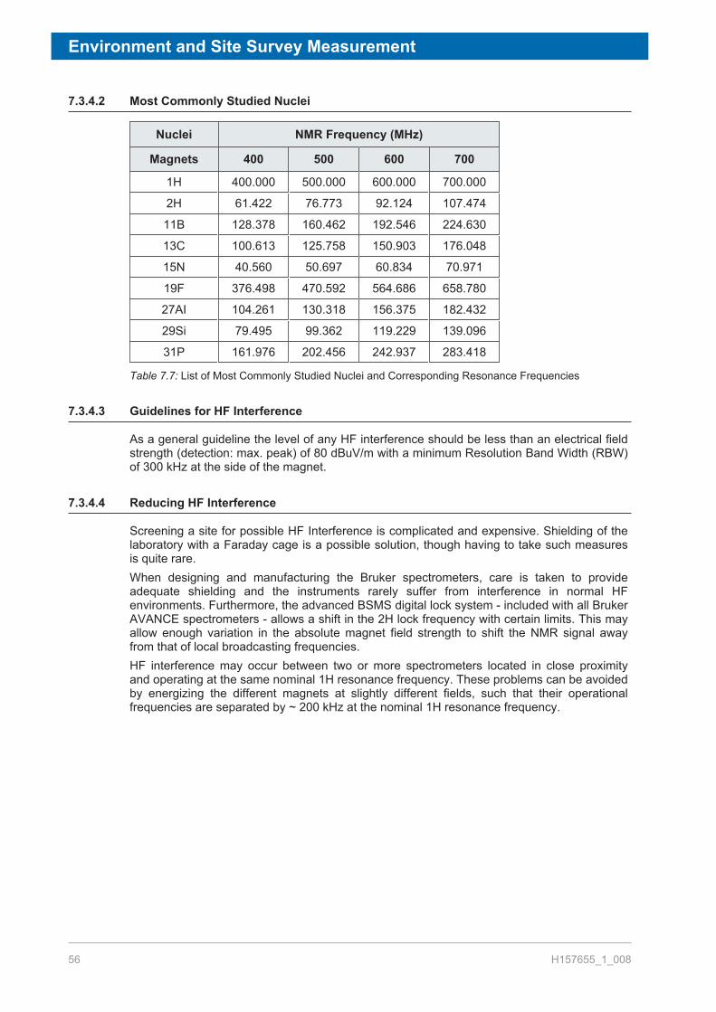
Environment and Site Survey Measurement
56 H157655_1_008
7.3.4.2 Most Commonly Studied Nuclei
Nuclei NMR Frequency (MHz)
Magnets 400 500 600 700
1H 400.000 500.000 600.000 700.000
2H 61.422 76.773 92.124 107.474
11B 128.378 160.462 192.546 224.630
13C 100.613 125.758 150.903 176.048
15N 40.560 50.697 60.834 70.971
19F 376.498 470.592 564.686 658.780
27AI 104.261 130.318 156.375 182.432
29Si 79.495 99.362 119.229 139.096
31P 161.976 202.456 242.937 283.418
Table 7.7: List of Most Commonly Studied Nuclei and Corresponding Resonance Frequencies
7.3.4.3 Guidelines for HF Interference
As a general guideline the level of any HF interference should be less than an electrical fieldstrength (detection: max. peak) of 80 dBuV/m with a minimum Resolution Band Width (RBW)of 300 kHz at the side of the magnet.
7.3.4.4 Reducing HF Interference
Screening a site for possible HF Interference is complicated and expensive. Shielding of thelaboratory with a Faraday cage is a possible solution, though having to take such measuresis quite rare.When designing and manufacturing the Bruker spectrometers, care is taken to provideadequate shielding and the instruments rarely suffer from interference in normal HFenvironments. Furthermore, the advanced BSMS digital lock system - included with all BrukerAVANCE spectrometers - allows a shift in the 2H lock frequency with certain limits. This mayallow enough variation in the absolute magnet field strength to shift the NMR signal awayfrom that of local broadcasting frequencies.HF interference may occur between two or more spectrometers located in close proximityand operating at the same nominal 1H resonance frequency. These problems can be avoidedby energizing the different magnets at slightly different fields, such that their operationalfrequencies are separated by ~ 200 kHz at the nominal 1H resonance frequency.

Utility Requirements
H157655_1_008 57
8 Utility RequirementsContents:
Electrical Power Requirements [} 57]Telecommunication [} 59]Compressed Gas [} 59]Cooling Water [} 64]Lighting [} 65]HVAC (Heating Ventilation Air Conditioning) [} 65]Emergency Ventilation During Installation and Quenches [} 68]Fire Detection System and Fire Extinguishers [} 71]
8.1 Electrical Power RequirementsWhen planning the electrical power requirements of your site make provision for extraequipment which you may install, e.g. personal computers, workstations, air conditioningsystems, etc.Each AVANCETM cabinet (except NanoBay) comes supplied with four spare electrical outlets(230V/10A) which can be used to power standard ancillary equipment. Two outlets aredesigned to power the NMR Workstation and Imaging cabinet (optional). This leaves twospare outlets for accessories such as the Sample Changers etc. The table in this section liststhe power requirements of other equipment which, because of their large power consumption,require power sources separate to that of the AVANCE cabinet.
Other Power Requirement Considerations• For installation of the AVANCE system a 230V / 16A outlet is needed for the turbo-pumps,
as well as an additional 230V / 16A outlet for the magnet power supply (during installationand service).
• A TwoBay with Solid Accessory 600/700 MHz can be approximated to a standard TwoBayplus High Power cabinet and so the total power requirements is 5 kW.
• The power requirements for the CP-MAS will depend on the amplifiers that are used. Thecontrol unit itself will not use more than 100W.
• If line voltage fluctuations exceed -5% to +10% a voltage stabilizer must be used. Thelifetime of the various electrical components in the spectrometer will also be lengthenedwhen a voltage stabilizer is used. Contact your local Bruker BioSpin office for moreinformation on voltage stabilizers.
• Where total interruption of power occurs frequently, you should consider installing a UPS(Uninterruptable Power Supply) possibly linked to an emergency back-up generator. Thisis particularly advisable when long-time experiments are to be run.
• The power supply to the spectrometer must be "clean" (no spikes), i.e. it must not sharewith air conditioners, compressors, etc.
• All grounding for mains in the lab must be connected together to avoid differences in earthpotential.

Utility Requirements
58 H157655_1_008
System andAmplifiers
Mains Supply PowerConsumption (kW)*
No. ofSpareElectricalOutlets
Length ofMainsCable (m)
TwoBay withBLARH100 +BLAX300
230V 50/60 Hz / 16A singlephase; or 208V 60 Hz / 20Asingle phase in USA
2.6 4 (230Vmax. 10amp.)
5.5
TwoBay withBLAXH300/50
230V 50/60 Hz / 16A singlephase; or 208V 60 Hz / 20Asingle phase in USA
2.2 4 (230Vmax. 10amp.)
5.5
TwoBay optimizedfor solids 300 to700 MHz
230V 50/60 Hz / 32A singlephase or 400V 50/60 Hz /16A triple phase; or 208V 60Hz / 30A single phase inUSA
5.0 4 (230Vmax. 10amp.)
5.5
OneBay withBLAXH100/50
230V 50/60 Hz / 16A singlephase; or 208V 60 Hz / 20Asingle phase in USA
1.62.2
4 (230Vmax. 10amp.)
5.5
NanoBay 230V 50/60 Hz / 16A singlephase; or 208V 60 Hz / 20Asingle phase in USA
1.0 --- 5.5
Imaging Cabinet 230V 50/60 Hz / 32A singlephase or 400V 50/60 Hz /16A triple phase; or 208V 60Hz / 30A single phase inUSA
2.4 --- ---
Bayvoltex Chillerfor MicroImagingSystems
230V 50/60 Hz / 16A singlephase or 208V 60 Hz / 20Asingle phase in USA
approx.0.45 kW
--- ---
BCU-I/BCU-II 230V 50/60 Hz / 16A singlephase or 208V 60 Hz / 20Asingle phase in USA (powerfor BCU-II must come fromseparate outlet).
0.45 kW(BCU-I)2.3 kW(BCU-II)
--- ---
UPS for CCU UPS requirements: At least 5 kW for the AVANCE and CCU.
UPS for AVANCESpectrometerCabinet
UPS requirements: At least 2.6 kW for the spectrometer cabinet(depends on configuration). The battery time must be selectedaccording to the maximum duration anticipated for a power failure.
* Includes the NMR workstation and computer monitor, and was measured using 2amplifiers operating at maximum output in CW mode. For systems fitted with additionalamplifiers allow 300W for each additional amplifier.Note: For the electrical specifications associated to the CryoProbe, CryoProbe - Prodigy,and the Bruker Nitrogen Liquifier accessories, refer to the relevant pages in CryoProbeand Other Accessories [} 83].
Table 8.1: Requirements of Basic System (2 Channels)

Utility Requirements
H157655_1_008 59
8.2 TelecommunicationPlease refer to the AVANCE NMR layout in chapter Floor Plan [} 73]. The following ports/connections are required:
• Telephone/data ports behind the workstation.• Ethernet cable between the AVANCE cabinet and the workstation.
8.3 Compressed GasSome components of the AVANCE system and the vibration isolators, which are integratedinto the magnet legs, operate with compressed gas.
8.3.1 General Requirements
Compressed gas line: The standard AVANCE system requires one compressed gas linewith at least two regulated outputs.Regulators: Each output should terminate with a regulator (including gage head) suited for apressure range of 0 - 8.6 bar (0 - 125 psi). The output of the regulator should allow the quickconnect for an 8 mm diameter gas tube..
• Compressed nitrogen gas needed for temperature control with VT experiments in order toachieve optimal NMR performance. For example, the BCU-I cooling unit requires a dewpoint of -51°C (-60°F) for the compressed gas.
• Compressed air or nitrogen gas for spinning.• Compressed air or nitrogen gas for sample ejection, and for the magnet’s vibration
isolation units.• Compressed air or nitrogen gas for the optional CryoProbe system.
8.3.2 Gas Supply
The gas supply used depends on the frequency of the system:• 400 MHz: Compressed air• 500 MHz: Nitrogen gas with >95% purity.• 600-800 MHz: Nitrogen gas with >96% purity.
Notes:• A nitrogen separator (offered by Bruker as an option) can be built into the AVANCE
cabinet as an available solution. This will produce the nitrogen gas required for VT work.However, this is not suitable for larger flow rates required by MAS experiments.The nitrogen separator is suitable for use with the BCU-I cooling unit. However thenitrogen output from the separator is not pure enough and this unit should not be usedwith a N2 exchanger or BCU-II cooling unit for low temperature work.
• If a CryoCooling unit is to be installed, a secondary regulator, T-split from the supply line isrecommended.
• The Emergency Sample Protection Device is used in conjunction with the CryoProbesystem, and requires a cylinder of air or nitrogen gas.

Utility Requirements
60 H157655_1_008
System Operating Pressure Recommended AverageFlow*
AVANCE + VT Unit 6-8 bar (80-120 psi) 43 l/min. (~1.52 cfm)
AVANCE + VT + SampleChanger
6-8 bar (80-120 psi) 55 l/min. (~1.95 cfm)**
AVANCE + MAS 6-8 bar (80-120 psi) 300 l/min. (~11 cfm)
* This is the actual consumption and minimum needed at the instrument input after theN2 supply (either a bulk tank, or a N2 separator). The sample lift to exchange a sampleneeds for about 1 minute 100 l/min. For a standard NMR system we expect 3...5 sampleexchanges (which are included in recommended flow).** A recommended flow of 100 liters/min. per sample for sample exchange (about 1minute), average consumption will depend on the number of samples being used. Typicalnumber of sample exchanges is up to 12 per hour (which is included in the recommendedaverage flow).For non-MAS work, if an air-compressor and N2 separator are used, the flowrequirements are 50% higher, i.e. 3 cfm. It is recommended to use a dual unit oil-less air-compressor rated at minimum double capacity of the specified requirement. Please referto the next section on air compressors.
Table 8.2: Pressure and Flow Requirements
8.3.3 Other Specifications
Oil Content: Purity: ISO 8573-1 2010 [1:1:0] (oil free).
Water Content: For the BCU-I cooling unit the compressed gas should have a dew point of -51°C (–60°F).For the BCU-II cooling unit, the dew point requirement is - 80°C (-112°F).For room temperature work and higher: Dew point of < 4°C (39.2°F).For low temperature work: The dew point must be at least 20°C (68°F) below the operatingtemperature.If a cooling unit is used, then the dew point of the compressed nitrogen should be at least10°C (50°F) below the temperature at the heat exchanger output.
Solid Impurities: Use 5 micron filters for high resolution NMR. For MAS probes use 1 micron filters. The filtersshould retain a minimum of 99.99% of the specified particles.
VT Nitrogen Gas Quality
Proton Frequency (MHz) Purity (volume percentage)
500 ≧ 95
600-800 ≧ 96
850-1000 ≧ 97
Table 8.3: VT Nitrogen Gas Quality (500 MHz and above)

Utility Requirements
H157655_1_008 61
8.3.4 Compressed Air System
When designing a suitable compressed air system the following points must be taken intoconsideration:
• To prevent magnetic impurities from entering the magnet use only copper or stainlesssteel lines. Do not use iron or steel pipes. Plastic piping is unsuitable where very low dewpoints are required. Water vapor in the air will permeate plastic piping limiting minimumdew points to typically -25°C.
• To avoid surges in the air pressure (e.g. during sample lift) install a container of 10-20liters in the air supply line to act as a buffer. Locate the buffer after the dryers in the supplyline. Buffer containers must meet the appropriate safety requirements. They must have aworking pressure of 16 bar and be proofed up to 30 bar. Use tanks which are internallycoated with water and acid resistant material. This will prevent corrosion from impuritiessuch as SO2.
The three major components in a suitable compressed air supply line include thecompressor, dryer and appropriate filters:
Figure 8.1: Example of a Typical Dryer/Filter System Setup
Filter 1: General purpose liquid and dust removal filter (0.1 mg/m3 - 0.1 ppm, 1micron).
Filter 2: High-efficiency dust, liquid and aeresol filter (0.1 mg/m3 - 0.01 ppm, 1micron).
When using a dryer/filter system setup, the following questions should be addressed:• Pressure loss in piping?• Efficiency loss in dryer?• Pressure loss in filter?• What is the required pressure?• What is the required flow rate?
Utility Requirements
62 H157655_1_008
8.3.4.1 Air Compressors
When choosing an air compressor the following points should be considered:• Ideally the compressor should be installed in a dust free, cool (use air conditioning as
required) and dry place.• The compressor must be oil-free. This can be achieved by using membrane or Teflon
coated piston and scroll compressors. The compressor should be fitted with a fine dustinlet filter.
• The compressor must be capable of delivering the required flow rate and pressure suitedto your particular system (see Compressed Gas Requirements). Generally thecompressor should be large enough so it does not run continuously (e.g. > 50% of thetime), which will cause overheating.
• The extra cost of choosing an oversized system may often be justified. The reduction induty cycles will lower maintenance costs and extend the life of the system. A suitablecompressor coupled to an adequate buffer will ensure a more constant flow rate leadingto better performance. When spinning, the system uses a constant flow of air, but surgeswill occur during sample lift.
• Take into account the pressure loss along the line between the compressor and the finalgate valve. The pressure drop depends on the pipe diameters. An internal diameter of 8mm has been found to be suitable. The plastic tubing used to carry the supply from thefinal gate valve to the console has an outside diameter of 8 mm and is supplied by Bruker.
• Some types of dryers, e.g., absorption dryers can use up to 25% of the air flow toregenerate the drying material. If this type of dryer is used then the output capacity of thecompressor must be sufficient to supply this requirement.
• Many compressors are fitted with dryer and a tray to collect excess water. Regularchecking of the dryer and emptying of the water collector will ensure trouble freeoperation. This arrangement is quite satisfactory in environments with normal humidity (<80%). However in areas of higher humidity (> 80%) a cooling coil with an automatic waterdrain must be fitted to the compressor outlet. This will ensure that filters do not becomeoverloaded.
• Although not directly concerned with air quality, compressors are a source of vibrationswhich may interfere with NMR performance. You should consider using a compressorfitted with a vibration damping housing if it is to be situated close to the spectrometer. Theoutput noise level should be < 75 dBA.

Utility Requirements
H157655_1_008 63
8.3.4.2 Dryers
Refrigeration DryersThis type of dryer removes moisture from gas by cooling to within a few degrees of thefreezing point of water. The condensed moisture is removed in a separator and drain trapmechanism located immediately downstream of the dryer. This drain should be valveswitched automatically.Advantages
• None of the compressed gas is wasted in regeneration which is more suitable if thecapacity of the compressor is marginal.
• Maintenance free.• Not as susceptible to oil mist contamination as adsorption dryers, thus do not have the
same need for pre-filters.Disadvantage
• These type of dryers are limited because of their inability to produce very low dew points.The recommended dew point for room temperature work of 4°C is only just achievable.Therefore if low temperature NMR is to be carried out, this type of dryer is unsuitable.
Absorbtion DryersThe air is passed through cartridges of synthetic zeolite known as Molecular Sieves. Thesieves are hygroscopic and retain water molecules when air is passed through them. Twosieves are normally used alternatively. A portion of the dry air output of sieve A is fed intosieve B to regenerate it. The amount used in regeneration is typically 15% but up to 25% maybe required for very low dew points. The process is automatically reversed at regular intervalswith the output of sieve B used to regenerate sieve A.Advantages
• Much lower dew points are achievable compared to refrigeration dryers.• Automatic Regeneration: Normally the sieves will last for many years if they do not
become contaminated with oil, e.g. from mist in the air.• The drying agent may be easily replaced.
Disadvantages• Up to 25% of throughput is used to achieve the automatic regeneration.• Requires the use of more dust filters.• Filters at the input (oil < 0.01 mg/m3) are required due to the susceptibility to oil
contamination from mist in the air.• The use of absorption dryers may lead to the generation of dust and so the dried air
output must be fed through an appropriate filter (1 micron).• These dryers require more maintenance than refrigeration dryers.• They can be noisy when switching between the two cartridges.• Due to the different absorption rates of nitrogen and oxygen the N2/O2 composition may
change. To prevent this, an absorption dryer should be placed between the compressorand buffer tank.

Utility Requirements
64 H157655_1_008
8.3.4.3 Filters
Micro-filters must be fitted as the last element in the supply line. For specification see thesection Other Specifications [} 60].Absorption dryers are prone to oil contamination and as such the input must be fitted with aoil filter (oil < 0.01 mg/m3 99.9% removal efficiency). To protect the dryers, regardless of type,you are advised to install a water filter and an oil filter between the compressor and the dryer.Adsorption dryers may generate dust and may need extra dust filters at the output.The output of refrigeration dryers must be fed through a carbon activated filter.Water filters must be fitted with automatic water drains as opposed to manual drains. The useof valve switched drains is strongly recommended. Floater switched drains have a tendencyto become jammed and hence require regular maintenance.If you are particularly concerned about oil contamination in the air supply then you mustconsider using a submicron filter followed by an activated charcoal filter as this combination isparticularly effective in removing oil.
8.4 Cooling WaterThe Ascend Aeon magnet system is equipped with a pulse tube cooler and a heliumcompressor, which requires cooling water to remove up to approximately 10 kW of dissipatedheat.Bruker recommends the installation of a dedicated cooling water loop serving the heliumcompressor. This may be achieved by using either a refrigerated indoor or outdoor chiller, ora water-water heat exchanger depending on the specific conditions and utilities available atthe customer site.It is strongly recommended to provide emergency backup cooling water to the heliumcompressor in case of failure of the main cooling water source. A secondary chiller or/anddomestic city water may be used as emergency backup. It is recommended to have anautomatic switch from the main cooling water source to the emergency backup water source.It is also essential that the chillers are connected to backup power from the emergencygenerator.
There are specific requirements for the cooling water parameters in order to maintain theoptimal operation of the helium compressor. These include water temperature, flow, andpressure differential. The acceptable ranges for these water parameters and also for thewater quality are listed in the dedicated manual for the helium compressor. Please contactBruker for the respective specifications concerning the cooling water requirements.
If the system is equipped with the CryoProbe option and the compressor is water cooled,then cooling water is also needed to remove the ca. 7.5 kW of heat output from the water-cooled type helium compressor used in conjunction with the CryoProbe. The cooling waterrequirements for the CryoProbe system are found in the chapter Helium Compressor - IndoorWater Cooled [} 86].When the magnet is equipped with a BNL and the water-cooled option, then cooling water isneeded to remove the ca. 2.5 kW of heat output from the water-cooled type heliumcompressor.

Utility Requirements
H157655_1_008 65
8.5 LightingOperation is most convenient when the computer monitor(s) may be viewed under subduedlighting. However, normal office lighting will be needed in other areas of the laboratory. Themost convenient arrangement is to have separately switchable lights using standard lightbulbs. Make sure that reflections from strong artificial light do not fall upon the monitorscreen. Care should also be taken to minimize reflections from sources such as windows.
• Do not direct spotlights toward the magnet; this could change the surface temperature.• Consideration should be given to the relative placement of lights to the air conditioning
inputs, which mostly contain the temperature sensors for the air conditioners. Otherwisethe switching of lights might result in a system over-reaction and a considerabletemperature change.
• Neon lights, choke ballast, and electronic ballast are generally not recommended within aradius of 2 meters from the magnet. LED with DC current are generally not a problemwithin this range.
• Lights should not be located directly above the magnets, as it may not be possible toservice the lights.
8.6 HVAC (Heating Ventilation Air Conditioning)Constant air pressure, temperature and humidity is crucial for high performance operation.Ideally, an absolute room temperature of between 17-25°C should be kept.Room should not fluctuate more than +/- 1°C per 24 hours for 300-500 MHz systems, and+/- 0.5°C per 24 hours for 600 MHz and above, near the magnet or cabinets. Even with smallchanges within this narrow range, it is essential that these are random and there is noperiodicity of temperature changes.Air drafts, particularly those created from air conditioning or heating systems, can havenegative effects on the magnet, thus the location and orientation of air-diffusers must preventthe air from blowing towards the magnet and spectrometer cabinet. If possible, it isrecommended to have the exhaust (air-return) closer to the NMR spectrometer equipment(AVANCE console, UPS, CryoCooling unit, BCU-I) that releases most of the heat output intothe space. This would help with removing the heat closer to its sources and ultimately helpwith the overall temperature stability in the room.
GradientsThe temperature stability guidelines above are essential for a given point in proximity to themagnet or console. Absolute temperature values at different elevations in the room can varyby a much greater tolerance.
Note: When NMR Lock is on and when Autoshim is used, the room should not fluctuatemore than +/- 1.5 °C per 24 hours.

Utility Requirements
66 H157655_1_008
The maximum humidity in the lab depends on the room temperature. There are parts on ornear the NMR spectrometer and the magnet system (like the nitrogen heat exchangers)which have temperatures of 14…16°C. When the room temperature is 25°C, with a humidityof 80 %, the dew point of this air is at 21.3°C. This means condensation may build up at theheat exchangers of the magnet and other parts like temperature units or shim coils.Therefore we recommend a dew point of 14-16°C in the laboratory (for the magnet parts) toavoid condensation at the location of cold parts. With a laboratory temperature of 17°C thehumidity can rise up to 67.7 % and with 25°C it will be only 41.4 %.
Temperature inthe NMR
laboratory
Maximum humidity for a dew point of
11 °C 12 °C 13 °C 14 °C 15 °C 16 °C
17 °C 67.7 % 72.4 % 77.3 % 82.5 % 88.0 % 93.8 %
18 °C 63.6 % 68.0 % 72.6 % 77.5 % 82.6 % 88.1 %
19 °C 59.7 % 63.8 % 68.2 % 72.8 % 77.6 % 82.7 %
20 °C 56.1 % 60.0 % 64.1 % 68.4 % 72.9 % 77.8 %
21 °C 52.8 % 56.4 % 60.2 % 64.3 % 68.6 % 73.1 %
22 °C 49.7 % 53.0 % 56.7 % 60.5 % 64.5 % 68.8 %
23 °C 46.7 % 49.9 % 53.3 % 56.9 % 60.7 % 64.7 %
24 °C 44.0 % 47.0 % 50.2 % 53.6 % 57.2 % 60.9 %
25 °C 41.4 % 44.3 % 47.3 % 50.5 % 53.8 % 57.4 %
Table 8.4: Maximum Humidity in the NMR Laboratory
Conditions other than these may warrant the installation of an air conditioner with appropriatehumidity controls.

Utility Requirements
H157655_1_008 67
8.6.1 Heat Dissipation into the Room
Most of the heat dissipated into the room is generated by the system electronics. The magnetitself does not dissipate any heat. The following table details the heat dissipation into theroom:
System Heat Dissipation into Room
AVANCE TwoBay (with 3 channels & BCU-I) 2.5 kW
AVANCE TwoBay (configured for solids) 5.0 kW
AVANCE OneBay 2.0 kW
AVANCE NanoBay 1.0 kW
Imaging Cabinet 2.4 kW
BCU-I, BCU-II BCU-I: 0.5 kW, BCU-II: 2.4 kW
Gradient Chiller 0.5 kW
CryoCooling Unit 0.8 kW
He Compressor (note: heat from the outdoor Hecompressor is not dissipated inside the room)
0.5 kW - residual
He Compressor CryoProbe - indoor water-cooled 0.5 kW
He Compressor CryoProbe - outdoor air-cooled 8.5 kW
He Compressor BNL - inside water-cooled 2.0 kW
He Compressor BNL - outside air-cooled 2.2 kW
Table 8.5: Heat Dissipation into the Room by Typical AVANCE Systems
8.6.2 System Stability
Air TemperatureThe heat dissipation of the magnet system is constant over time. It is essential to minimize oravoid short term oscillations of the HVAC system, and provide a continuous slow flow of airthat in turn reduces the speed of any temperature changes. It is recommended to have acontinuous and slow exchange of air in the laboratory, hence minimizing fluctuations.
Air Diffuser and Return Ducts• Avoid any air drafts in the room, especially towards the magnet or system electronics.• Use low velocity diffusers or a perforated duct (e.g. a duct sock).• In order to remove heat directly from the source it is recommended placing the air return
ducts closer to the rear side of the system electronics.

Utility Requirements
68 H157655_1_008
8.7 Emergency Ventilation During Installation and QuenchesDue to the large amount of liquid helium contained in the magnet, an emergency exhaustsystem may be required to prevent O2 depletion during a magnet quench.Likewise, during the installation, refilling and cooling of superconducting magnets, largevolumes of nitrogen or helium gases may be generated under certain conditions. Althoughthese gases are inert, if generated in large enough quantities, they can displace the oxygenin the room causing potential danger of suffocation.The following table lists the maximum helium capacity and the typical gas flow rates forhelium gas during a quench for current magnet systems. Generally, the gas flow rate is equalto half the volume in one minute.
Total Volume of Gas and Maximum Helium Gas Flow
Magnet Type Total Volume of HeGas (m3)
Maximum He GasFlow (m3/min.)
400/54 Ascend Aeon 196.7 98.35
500/54 Ascend Aeon 182.0 91.0
600/54 Ascend Aeon 262.5 131.25
700/54 Ascend Aeon 230.3 115.15
Table 8.6: Total Gas Volume and Maximum He Gas Flow: Standard Bore 54 mm
Magnet Type Total Volume of HeGas (m3)
Maximum He GasFlow (m3/min.)
400/89 Ascend Aeon 269.5 134.75
500/89 Ascend Aeon 262.5 131.25
600/89 Ascend Aeon 225.4 112.7
700/89 Ascend Aeon 236.6 118.3
Table 8.7: Total Gas Volume and Maximum He Gas Flow: Wide Bore 89 mm
Regarding the emergency gas exhaust, important considerations include, but are not limitedto, the following:
• Amount of liquid helium: Taking the 750 WB US2 magnet as an example, the totalamount of liquid helium is 473 liters. In case of a quench, the liquid transforms into gasand expands by a factor of 740. Therefore, the total amount of helium evaporated gas incase of a quench will be ca. 350 m3 (12,360 ft3).
• Maximum helium gas flow: The maximum flow of helium gas is calculated on theassumption that half of the volume of liquid evaporates in 1 minute, thus the maximumflow would be 175 m3 (6,180 ft3) for the 750 WB US2 magnet. The gas should be removedfrom the room immediately through an emergency exhaust system.
• O2 level sensors: Oxygen level sensors are required to detect low O2 levels within thelaboratory for each system. One sensor is needed above the magnet for detecting low O2levels due to He gas exhaust in case of a quench or during He fills. An additional sensor isneeded close to the floor for detecting low O2 levels due to N2 gas exhaust during magnetcooling or regular N2 fills. In case of placing the magnet inside a pit, a third sensor isneeded inside a pit to detect low O2 levels from N2 gas.

Utility Requirements
H157655_1_008 69
8.7.1 Emergency Exhaust Solutions
In many cases doors and windows will provide sufficient ventilation in larger rooms. It isimportant to compare the volume of helium gas that would be released after a quench andthe space volume of the NMR magnet room, in order to determine the optimum and practicalsolution for emergency ventilation. In general it is recommended that an emergency exhaustsystem be installed in smaller rooms, or rooms not connected to the outside. The followingexhaust solutions are recommended:
Passive ExhaustThis system is based on louvers in the ceiling, or upper parts of outside walls, that open updue to the pressure of helium gas.
Active ExhaustIn addition, an active system based on a purge fan and exhaust duct close to the ceiling isrecommended. This way, adequate exhaust of cryogenic gases will be provided not onlyduring a quench, but also during the initial cooling of the magnet and regular cryogen refills.Normally it is sufficient to operate this fan manually, as the probability of an unattendedquench after the installation is rather low.If desired, this fan can be operated with an automatic switch:
• It may be connected to the O2 sensors so it turns on automatically when the O2 leveldrops below the safety set point.
• It should be installed in addition to a manual switch.• Measures should be taken to prevent it from being turned on during a fire.
Quench PipesThis solution may be needed as a last resort solution when the laboratory is small and anyof the other options are not sufficient to ensure safety after a magnet quench.This solution is based on a pipe connected directly to the magnet, which is then routed to theoutside of the building. It is important to note the following:
• The helium exhaust from the magnet should be vented directly to the outside of thebuilding.
• The ducts should have sufficient diameter to avoid excessive pressure build-up due to theflow impedance of the duct.
• The location of the exit end of the duct must not be accessible to anyone other thanservice personnel. In addition the exit opening should be protected from the ingress ofrain, snow, animals, etc.
• It is also essential that any gas which vents from the exhaust duct cannot be drawn intothe air conditioning or ventilation system intakes. The location of the duct’s output shouldbe carefully sited to prevent this from happening during any adverse atmosphericconditions and winds.
• Insulation of exhaust piping should also be provided to prevent cold burns and O2condensation during a quench.
Please contact Bruker if the implementation of quench pipes is planned!

Utility Requirements
70 H157655_1_008
Figure 8.2: Emergency Quench Pipes
PitsWhen a magnet is installed in a pit, it is important to ensure there is continuous air-flow(exhaust) within the pit. This is done to prevent any buildup of nitrogen gas in the confines ofthe pit. A low exhaust and an additional oxygen sensor down in the pit are recommended.Additional emergency ventilation may also be necessary and the oxygen sensor mounted inthe pit should trigger an increased rate of exhaust.
Exhaust for Ceiling SoffitsA soffit is a hole that has been cut in the ceiling to facilitate cryogen fills and/or the magnetinstallation. Though it is not required to install ventilation in a soffit, it is important tounderstand that the soffit will be the first area to fill up with helium gas during a quench orduring a helium fill. It is important to elicit extra caution in this case.A passive louver or an exhaust duct with fan are practical solutions when soffits are used.This will prolong the cycle of the magnet between rebuilds, by preventing helium gas build upin the soffit during refills.
Air Conditioning as an ExhaustIt is recommended that the air conditioning system be adequate to dissipate the sudden gasbuildup during a quench. In addition the air conditioning must have a safety feature whichdraws all the air out of the room and brings fresh air in during a quench, rather than justrecirculating the old air through the system. The air conditioning system could, for example,be connected to an oxygen level sensor.Please contact Bruker for further information on exhaust solutions.

Utility Requirements
H157655_1_008 71
8.8 Fire Detection System and Fire ExtinguishersRooms containing NMR magnets should be equipped with temperature sensors for firedetection. These must respond only to a sudden rise of temperature, and not be triggered bya quench (sudden drop of temperature).Optical smoke detectors cannot discriminate between smoke from a fire and fog from either ahelium refill or caused by a quench, so these may not be used. Combined heat and smokedetectors are recommended instead.Fire extinguishers in the vicinity of the magnet room must be non-magnetic (stainless steelor aluminum). It is the obligation of the customer to inform the local fire department about thedangers of magnetic fields. These magnets stay at field for a long time even in a most blazingfire!Ceiling sprinkler heads should be made of metal instead of glass. A quench could falselytrigger the alcohol-filled glass vials, which can shatter in the presence of cold helium gas.Sprinklers should not be located directly over the magnet.Any sprinkler lines or other metal pipes located above the magnet should be thermally-insulated to prevent O2 condensation or water freezing in the line from the large amount ofcold He gas following a magnet quench.A pre-action sprinkler system is recommended, as it is not loaded with water, but isactivated through an interlock mechanism enabling the water to fill the lines in case of a fire.

Utility Requirements
72 H157655_1_008

Floor Plan
H157655_1_008 73
9 Floor Plan
9.1 Magnet LocationWhen locating the magnet, certain considerations must be made with regards to thelaboratory environment:
• To increase magnet homogeneity, the magnet should be located away from permanentiron structures such as support beams in walls and floors. Reference: ElectromagneticInterference [} 52].
• To increase temperature stability, the magnet should not be placed in direct sunlight ornear any artificial heat source. The magnet should also not be placed under or in closeproximity to air-vents or in an area that experiences air drafts. Air should not be blowndirectly down or towards the NMR magnet.
• When possible, avoid a situation where a significant stray field (>5 G / 0.5 mT) extendsinto adjacent rooms.
• There should be free access to the magnet from all sides.
Figure 9.1: Top View of an Ascend Magnet

Floor Plan
74 H157655_1_008
9.2 Dimensions and Mass of EquipmentThe floor of the NMR laboratory must be sufficiently strong to support the magnet, thespectrometer, and other ancillary equipment. The following tables provide the dimensionsand weights of equipment, and the footprint and weight of magnets (filled with cryogens andincluding stand). The assembly of the magnet system, the magnet energization and refillswith liquid helium require additional ceiling height.
Component Width (m) Depth (m) Height (m) Weight (kg)
AVANCE TwoBay 1.31 0.83 1.55 454
AVANCE OneBay 0.69 0.83 1.29 ~210
AVANCE NanoBay 0.45 0.88 0.71 130
Table / Workstation 1.20 1.00 0.75 68
MicroImaging Cabinet 0.69 0.83 1.55 205 / 150
BCU-I 0.50 0.55 0.48 46
BCU-II 0.55 0.59 0.74 74
Prodigy Unit 0.60 0.40 0.46 68
For the CryoProbe option refer to CryoProbe and Other Accessories [} 83].
Table 9.1: Dimensions and Weights of NMR Equipment
9.3 Floor LoadThe floor must be sufficiently strong to support the mass of the equipment, plus the weight ofany installation devices, e.g. hoists etc. The floor must also be as rigid as possible to reducethe effects of vibration.The overall floor load may be calculated from the total magnet weight distributed over theoverall footprint of the magnet.The magnet is supported by a total of 9 small pads (3 pads per post). The maximum pointload may be calculated by the total weight of the magnet distributed over the total contactarea of the 9 points. Each pad is circular and has a diameter of 80 mm.

Floor Plan
H157655_1_008 75
Magnet Dimensions and MassThe values in the following table correspond to the following figure:
Figure 9.2: Magnet Dimensions
A. Maximum magnet diameterB. Magnet height from the floor, including stand.C. Overall footprint diameterRefer to the Magnet Dimensions and Total Weights table for the values of A, B, and C.
Magnet Type AMaximum
MagnetDiameter
(m)
BMagnet Heightfrom the Floor
Including Stand(m)
COverall
FootprintDiameter
(m2)
Total MagnetWeight incl.
Stand &Cryogens
(kg)*
400/54 Ascend Aeon 1.46 2.27 1.70 ~640
500/54 Ascend Aeon 1.46 2.27 1.70 ~740
600/54 Ascend Aeon 0.95 2.61 1.98 ~1060
700/54 Ascend Aeon 0.95 2.61 1.98 ~1360
* With standard magnet stand, the weight with optional stands will vary.
Table 9.2: Magnet Dimensions and Weight: Standard Bore 54 mm

Floor Plan
76 H157655_1_008
Magnet AMaximum
MagnetDiameter
(m)
BMagnet Heightfrom the Floor
Including Stand(m)
COverall
FootprintDiameter
(m2)
Total MagnetWeight incl.
Stand &Cryogens
(kg)*
400/89 Ascend Aeon 0.90 2.86 2.25 ~1050
500/89 Ascend Aeon 0.90 2.86 2.25 ~1130
600/89 Ascend Aeon 0.90 2.86 2.25 ~1370
700/89 Ascend Aeon 1.05 3.03 2.74 ~1990
* With standard magnet stand, the weight with optional stands will vary.
Table 9.3: Magnet Dimensions and Weight: Wide Bore 89 mm
9.4 Floor TypesGenerally a liquid nitrogen resistant floor material must be used, such as PVC or woodthat has been painted or varnished. Unfinished wood must not be used as this will absorbliquid nitrogen. This also implies that wood floors must be regularly maintained to helpprevent absorption.Many of the system components contain highly sensitive electronic devices that must beprotected from Electrostatic Discharge (ESD) by proper floor covering and groundingpractices.To prevent ESD damage in the magnet room, the system must be installed on an ESDresistant flooring such as vinyl, and properly grounded. One of the most importantcharacteristics of an ESD resistant floor is its ability to conduct charges to ground. Thesecond most important aspect is its anti-static property.
9.5 Magnet PitsWhen the magnet must be sited in an existing magnet pit, pay attention to the following:
• Special rigging equipment and a temporary platform to support and lower magnet insidethe pit.
• Continuous ventilation and emergency exhaust inside the pit (please refer to special notesrelated to pits in sections HVAC (Heating Ventilation Air Conditioning) [} 65] andEmergency Ventilation During Installation and Quenches [} 68]).
• Magnet refills and access for transport dewars.• Cable lengths.• Siting the BCU-I or BCU-II cooling unit.• Siting the CryoPlatformTM.
Consult your local Bruker Installation Engineer for details.

Floor Plan
H157655_1_008 77
9.6 Magnet PlatformFor smaller magnet systems, ladders and small platforms are most commonly used tofacilitate sample insertion, cryogen fills, etc.Ladders for platforms must be constructed of wood or aluminum to keep magneticinterference down to a minimum.If climbing a ladder is not a feasible option, a magnet platform may be required. These aretypically built to facilitate sample insertion on the larger systems (600 MHz and up), howeversmaller platforms can be used on smaller systems.The platform must be constructed of wood or other non-magnetic material. It mustaccommodate the magnet and provide safe access for sample insertion and cryogen fills.Consult you Bruker office for further guidelines when using a magnet platform.
Figure 9.3: Example of a Simple Magnet Platform
9.7 Helium Flex LinesThe purpose of the helium flex lines is to transport the helium gas from the compressor to thecold head and back. The flex lines are isolated and are usually placed on the floor.
• The preferred route is to keep the helium flex lines at floor level. The lines exit the rotaryvalve column close to the floor, and continue to the compressor. The minimum bendingradius of 50 cm must be respected.
• It is always important to route the lines such that tripping hazards and obstructions areavoided, and to protect the physical integrity of the flex lines at all times.

Floor Plan
78 H157655_1_008
9.8 Maximum Field Strengths for NMR EquipmentOnce the location of the magnet has been decided, it is time to determine where theremainder of the equipment will be placed. Protection of motors and electronics frommagnetic stray fields is crucial.
Unit Maximum Field Strength
AVANCE cabinet 1.0 mT (10 G) line
BCU-I, BCU-II 5.0 mT (50 G) - max. 2.7m from magnet center
LCD computer monitor* 1.0 mT (10 G)
Computers e.g. NMR workstation, PC 0.5 mT (5 G)
Printer, plotter 0.5 mT (5 G)
CryoProbe system components (e.g. Hecompressor, He steel cylinder and itstransport path)
0.5 mT (5 G)
CryoCooling unit 5.0 mT (50 G)
Gas cylinders 0.5 mT (5 G)
Heavy metal office furniture e.g. filingcabinet**
0.5 mT (5 G) - not recommended in magnetroom
Movable metal chair Not recommended in magnet room
* The working place for personnel should be outside the 0.5 mT (5 G) line. An additionalLCD monitor and keyboard can be located at the 1.0 mT (10 G) line for probeadjustments etc.** Use wooden furniture if access during critical measurements is required.
Table 9.4: Maximum Field Strength for NMR Equipment
9.9 Cabinet PositionThe various units within the AVANCETM cabinet, especially the acquisition computer, must bekept at a minimum distance from the magnet. Protection of the acquisition computer anddigital electronics from the magnet’s stray field is best achieved by positioning the cabinet sothat the acquisition computer is no closer than the 1.0 mT (10 G) line. Any ancillary cabinetssuch as microimaging must also be placed outside the 1.0 mT (10 G) line. To allow adequateventilation for the cabinet, it must be positioned no closer than 30 cm from the back of thecabinet to any walls. For service access to the rear, there must be sufficient space for thecabinet to be pulled out from the wall.For ease of cabling, locate electrical outlets andcompressed air supply close to the rear of the cabinet.
9.10 Worktable PositionMagnetic storage devices are sensitive to the stray field and attention must be given to theirposition relative to the magnet.
• The workstation and additional disks, are normally placed on the worktable, and shouldnot be exposed to fields greater than 1.0 mT (10 G).
• For convenience of operation, no direct light should fall on the LCD panel, nor shouldthere be a strong light source at the back of the panel. A separate dimmer or at leastpartial switching is recommended for the lights in the worktable area.

Floor Plan
H157655_1_008 79
9.11 Service Access RequirementsThe following recommendations will ensure that there is sufficient space for accessing thesystem, as well as providing adequate ventilation:
• Ventilation: A minimum of 30 cm must left between the back of the cabinet and any wall toensure proper ventilation.
• Service access - AVANCE: Sufficient space (~ 60 cm) must be left in front of the AVANCEso the cabinet may be pulled away from the wall for service. Service access to the sides isnot required.
• Service access - Magnet: There must be enough space between the magnet legs and thewall such that a service person can walk all the way around the magnet. Also, whenrefilling the cryogen levels, large dewars must be brought close to the magnet. Ensure thatthe magnet room is suitably spacious to allow easy access for the dewars. If a platform isnot used then there must also be enough room for a ladder. As a rule of thumb themagnet must be accessible over at least half of its circumference for a radial distance of 2m from the side of the magnet and be no closer than 0.8 m to the nearest wall.
• Service access – Pulse Tube Cooler: Access to the pulse tube cooler is required, e.g. if noplatform is used, it must be possible to place the ladder or – even better – somescaffolding right next to the rotary valve column.
The following are miscellaneous, but important things to think about when creating aworkable floor plan:
• For ease of cabling, locate electrical outlets and compressed air supply close to the rear ofthe cabinet and by the magnet.
• The door to the magnet room must be easily accessible from all parts of the room. It isadvantageous to have the doors located so that traffic though the room does not approachthe magnet. The door to the magnet room should swing out to allow for a rapid and easyexit in case of an overpressure from cryogenic gases.
• As a rule gas cylinders must be stored outside the room. If for any reason they must beplaced in the magnet room located as far away from the magnet as possible and securedproperly to a wall well outside the 5 Gauss.
• Ensure that convenient and safe pathways are available so that cryogen transport dewarscan easily be moved into and out of the magnet room. This includes making sure that thecryogen dewars do not run over cabling, and that the equipment/furniture is located toallow for access.
• Make provision for sample/solvent preparation and storage space, documentation storagespace, personal computers, printer/plotter tables, workstations etc.
• Under no circumstances should movable office chairs made of magnetic material be usedin the laboratory.
• Make provision for installing a telephone and lines for, e.g. Internet access. It is mostconvenient if the operator can use the phone while sitting at the spectrometer worktable.
Finally, before a final layout is decided, consider future equipment that may need to beinstalled. Remember that once installed, the magnet must not be moved.
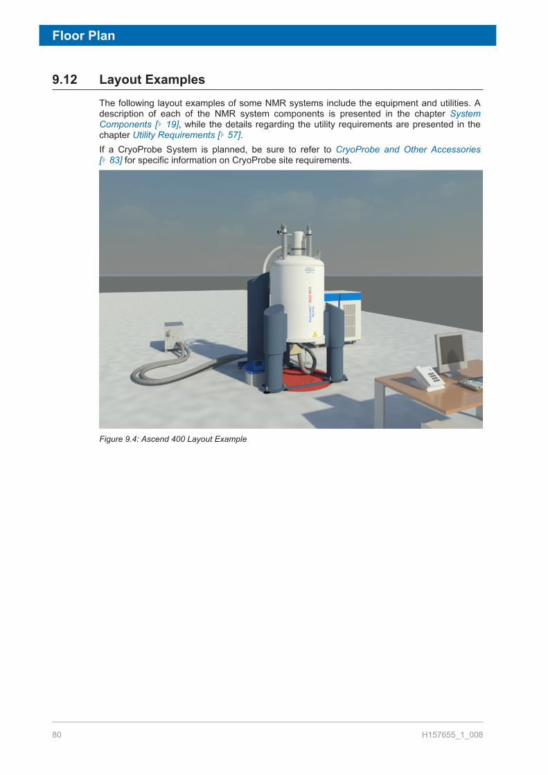
Floor Plan
80 H157655_1_008
9.12 Layout ExamplesThe following layout examples of some NMR systems include the equipment and utilities. Adescription of each of the NMR system components is presented in the chapter SystemComponents [} 19], while the details regarding the utility requirements are presented in thechapter Utility Requirements [} 57].If a CryoProbe System is planned, be sure to refer to CryoProbe and Other Accessories[} 83] for specific information on CryoProbe site requirements.
Figure 9.4: Ascend 400 Layout Example

Floor Plan
H157655_1_008 81
Figure 9.5: Top View of the Ascend 400 Magnet
1 AVANCE Console 7 Preamplifier2 Temperature Control Unit BCU I 8 Sample Changer3 Magnet System 9 Damping Post for CryoProbe
Transfer Line4 0.5 mT (5 Gauss) Line 10 He Gas Cylinder 6.0 for CryoPlatform5 Operator’s Desk 11 CryoPlatform6 Cryocooler Cold Head with Noise
Cover

Floor Plan
82 H157655_1_008

CryoProbe and Other Accessories
H157655_1_008 83
10 CryoProbe and OtherAccessoriesThe CryoProbe accessory for the AVANCE™ Series NMR Spectrometers offers dramaticincreases in signal to noise ratio (S/N) by reducing the operating temperature of the NMR coilassembly and the preamplifier.The CryoProbe accessory consists of two major components: the CryoProbe and theCryoPlatform. The CryoProbe is similar to a standard probe, however contains cryogenicallycooled RF coil and electronics. The CryoPlatform, which provides cryogenic cooling for theCryoProbe, is made up of:
• CryoCooling Unit with control electronics.• Helium Compressor (along with any associated cooling equipment).• Helium Gas Cylinder (for purging of the CryoProbe).• Helium transfer lines and transfer line support.
The CryoCooling Unit must be sited adjacent to the magnet, whereas the Helium Compressorand Helium Gas Cylinder may be sited remotely. The first step in the site planning involvesreview of the magnet area to determine if floor space is available to accommodate theCryoCooling Unit. The CryoCooling Unit is optimally located level with the magnet. Otherconfigurations, such as magnet pits that can not accommodate the CryoCooling Unit, requirespecial consideration.

CryoProbe and Other Accessories
84 H157655_1_008
Figure 10.1: CryoProbe System Overview
Refer to the layout examples for more information.

CryoProbe and Other Accessories
H157655_1_008 85
10.1 CryoCooling UnitThe CryoCooling Unit is installed adjacent to the magnet outside the 50 Gauss (5 mT) line.The shim cable must be 180º from the CryoProbe front plate. The shim stack may be rotatedif necessary.
Dimensions: Width: 68 cmDepth: 89 cmHeight: 96 cm
Weight: 400 kg
Voltage:Required external fuseupstream:
230 V AC +/- 10%, 1 phase, 50-60 Hz.T 10 A (T = time-lag fuse)
Power consumption: Peak 0.8 kWAverage 0.5 kW(systems produced before June 2005: peak power of1.5 kW)
Acoustic noise: Maximum 61 dB(A) 2 meters distant
Maximum room ambienttemperature:
30°C. No operation above this temperature isapproved.
Helium gas supply: A high purity helium (He) gas cylinder (6 N = 99.9999%or better, maximum impurity concentration 1 ppm).
Compressed air or nitrogensupply:
With a pressure of > or = to 4.5 bar.
Position: Outside 50 Gauss (5 mT) stray field.
Table 10.1: CryoCooling Unit Specifications
10.2 Helium CompressorsThe next step in the site planning for a CryoProbe accessory involves determining the typeand location of the helium compressor. Since the helium compressor generates aconsiderable amount of heat (7.5 kW average, 8.5 kW peak), it must be cooled to preventoverheating. Bruker offers both water cooled and air cooled helium compressors. In eithercase, placing the compressor in a remote room (allowing He gas flex lines up to 20 m toreach the CryoCooling unit) or an enclosure will keep the noise of the unit out of yourlaboratory. Outdoor helium compressors may be sited at increased distances allowing He gaslines up to 40 m to reach the CryoCooling Unit.
10.2.1 Available Models
Three models of helium compressors are currently available. All the compressors must besited outside the 5 Gauss (0.5 mT) line, generate the same amount of heat (7.5 kW average)and have the same power requirements (3 Phase, 208 V). The correct helium compressor foryour laboratory may be determined based on the desired location for the unit (indoor,outdoor, and distance from the CryoCooling Unit) and the availability of a chilled watersupply. Helium transfer lines connect the helium compressor to the CryoCooling unit and areavailable in several different lengths as shown below.

CryoProbe and Other Accessories
86 H157655_1_008
10.2.1.1 Helium Compressor - Indoor Water Cooled
• Requires chilled water source (supplied by customer) with a flow and temperature withinthe specified admissible ranges shown in the plots below. It is important that not only thetemperature stays below the maximum temperature threshold but also the flow is notgreater than the upper threshold shown. Caution: Do not use demineralized or deionizedwater.
• The water supply and return lines to the He compressor should be fitted with temperature,flow, and pressure gauges that are visible. The water hoses from the water lines to the Hecompressor should be 3/4" in size. These hoses are not supplied with the CryoProbesystem, and are to be provided by the customer.
• It is recommended to isolate the cooling water loop for the He compressor from thebuilding water system by using either a refrigerated chiller or a water-water heatexchanger. If building cooling water is not available, an air-cooled indoor or outdoor chillermay be used.
Figure 10.2: Admissible Ranges for the Temperature and Flow of the Cooling Water.
Figure 10.3: Cooling Water Typical Flow Characteristics

CryoProbe and Other Accessories
H157655_1_008 87
Characteristics
Inlet Temperature Range [°C] (°F) [4.0 ~ 28.0] (39.2 ~ 82.4)
Inlet Pressure Range [MPa] (psig) [0.10 ~ 0.69] (14.5 ~ 100)
Flow Rate [liter/min.] (gallon/min.) [4.0 ~ 10.0] (1.1 ~2.6)
Pressure Drop [MPa] (psig) [0.025 ~ 0.085] (3.55 ~ 12.1)
Heat Output [kW ] (BTU/Hr) intothe water (residual of 0.5 kW intoair)
<Steady State>[< 6.5] (< 22180) for 50Hz[< 7.5] (< 25590) for 60Hz<Maximum>[< 7.2] (< 24570) for 50Hz[< 8.3] (< 28320) for 60Hz
Quality
pH ValueElectrical ConductivityChloride IonSulfate IonM-AlkalinityTotal HardnessCalcium HardnessIonic SilicaIronCopperSulfide IonAmmonium ionResidual ChlorineFree Carbon DioxideStability IndexSuspended MatterParticle Size
6.5 to 8.2 at 25 °C (77 °F)< 80 mS / m< 200 mg/liter< 200 mg/liter< 100 mg/liter< 200 mg/liter< 150 mg/liter< 50 mg/liter< 1.0 mg/liter< 0.3 mg/literNone, Not detectable< 1.0 mg/liter< 0.3 mg/liter< 4.0 mg/liter6.0 to 7.0< 10 mg/liter< 100 μm
Table 10.2: Cooling Water Specifications
• Ambient operating temperature 5–28ºC.
Figure 10.4: Helium Compressor - Indoor Water Cooled

CryoProbe and Other Accessories
88 H157655_1_008
10.2.1.2 Helium Compressor - Indoor Air Cooled
• The room air handling system must be able to dissipate 7.5 kW of heat.• Siting this helium compressor in the same room as the NMR is not recommended.• Ambient operating temperature 5–28ºC.
Figure 10.5: Helium Compressor - Indoor Air Cooled
10.2.1.3 Helium Compressor - Outdoor Air Cooled
• The Outdoor Air Cooled helium compressor consists of an Outdoor Unit and an IndoorUnit.
• The outdoor unit is specified to operate between the temperatures of –30ºC to 45ºC.
Figure 10.6: Helium Compressor - Outdoor Air Cooled

CryoProbe and Other Accessories
H157655_1_008 89
10.2.2 Space Requirements and Specifications
10.2.2.1 Indoor Helium Compressors
The indoor helium compressors (air or water cooled) have space requirements to allow forairflow and servicing the unit. The minimum room space needed is 1.25 m (width) x 0.8 m(depth) x 0.7 m (height).
Sumitomo Type: F-50L F-50H CSA-71A
Type of Compressor: Water-cooled Water-cooled Air-cooled
Dimension: Width: 45 cmDepth: 48.5 cmHeight: 59.1 cm
Width: 45 cmDepth: 48.5 cmHeight: 59.1 cm
Width: 55 cmDepth: 55 cm
Height: 88.5 cm
Weight: 120 kg 120 kg 140 kg
Voltage: 3 x 200 V @ 60 Hz 3 x 400 V (380,400, 415 @ 50 Hz,or 460, 480 @ 60
Hz
3 x 200 V @ 50/60Hz US no plug
supplied
Mainly deliverd to: USA/CA/JP EU/CH USA/CA/JP
Operating Current: 26 A 13 A 25 A
Minimum Circuit Ampacity: 35 A 17 A 35 A
Maximum Fuse Size: 60 A 30 A 60 A
Compressor LRA: 160 A 75 A 100 A
Power RequirementsMinimum:Recommended:
9 kVA12 kVA
9 kVA12 kVA
9 kVA12 kVA
Power ConsumptonCool Down max. 50/60 Hz:Steady State max. 50/60Hz:
7.2/8.3 kW6.5/7.5 kW
7.2/8.3 kW6.5/7.5 kW
7.2/8.3 kW6.5/7.2 kW
Water supply to removethe heat load (coolingpower > 8.3 kW):
Flow: 420 l/hourTemperature: 4-28°CWater Quality: PH 6.5-8.2Hardness: mg[CaCo3]/l < 200Molybdate-reactive silicate: < 50 mg/lSuspended matter: < 10 mg/lMaximum pressure: < 7 bar (100 PSI)
---
Helium Gas Supply: A high purity helium (He) gas cylinder (6 N = 99.9999% orbetter, maximum impurity concentration 1 ppm).
Acoustic Noise: Maximum 60 dB(A), 2 meters distant.
Ambient OperatingTemperature:
5 to 28°C (41 to 82.4°F) 30°C
Table 10.3: Technical Data for Indoor Compressors
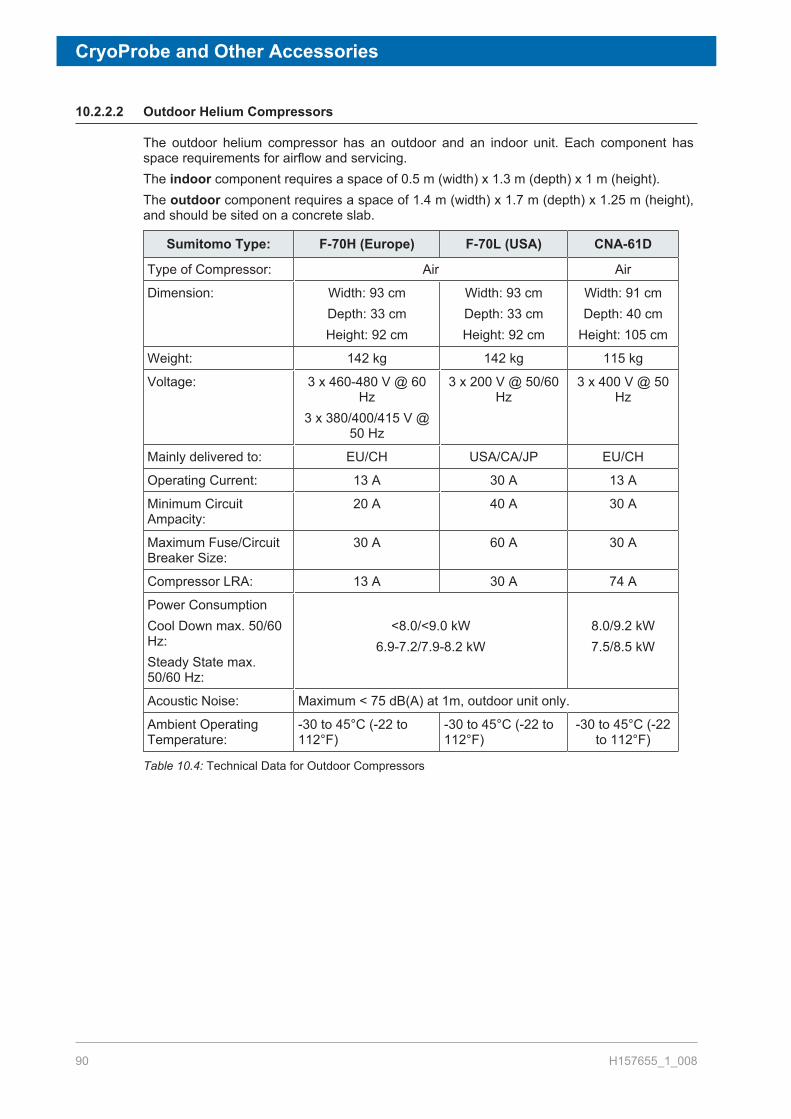
CryoProbe and Other Accessories
90 H157655_1_008
10.2.2.2 Outdoor Helium Compressors
The outdoor helium compressor has an outdoor and an indoor unit. Each component hasspace requirements for airflow and servicing.The indoor component requires a space of 0.5 m (width) x 1.3 m (depth) x 1 m (height).The outdoor component requires a space of 1.4 m (width) x 1.7 m (depth) x 1.25 m (height),and should be sited on a concrete slab.
Sumitomo Type: F-70H (Europe) F-70L (USA) CNA-61D
Type of Compressor: Air Air
Dimension: Width: 93 cmDepth: 33 cmHeight: 92 cm
Width: 93 cmDepth: 33 cmHeight: 92 cm
Width: 91 cmDepth: 40 cm
Height: 105 cm
Weight: 142 kg 142 kg 115 kg
Voltage: 3 x 460-480 V @ 60Hz
3 x 380/400/415 V @50 Hz
3 x 200 V @ 50/60Hz
3 x 400 V @ 50Hz
Mainly delivered to: EU/CH USA/CA/JP EU/CH
Operating Current: 13 A 30 A 13 A
Minimum CircuitAmpacity:
20 A 40 A 30 A
Maximum Fuse/CircuitBreaker Size:
30 A 60 A 30 A
Compressor LRA: 13 A 30 A 74 A
Power ConsumptionCool Down max. 50/60Hz:Steady State max.50/60 Hz:
<8.0/<9.0 kW6.9-7.2/7.9-8.2 kW
8.0/9.2 kW7.5/8.5 kW
Acoustic Noise: Maximum < 75 dB(A) at 1m, outdoor unit only.
Ambient OperatingTemperature:
-30 to 45°C (-22 to112°F)
-30 to 45°C (-22 to112°F)
-30 to 45°C (-22to 112°F)
Table 10.4: Technical Data for Outdoor Compressors

CryoProbe and Other Accessories
H157655_1_008 91
10.3 Helium CylindersThe next step in the site planning for a CryoProbe accessory involves determining thelocation for the helium gas cylinder. A research grade helium cylinder (grade 6.0, 99.9999%)is supplied by the customer and is connected to the CryoCooling unit. The cylinder must beoutside the 5 Gauss line in a serviceable location (i.e. changing the bottle should not interferewith nearby magnets). The helium regulator and a special He gas hose are supplied byBruker.Two lengths for the He gas hose line are available (10 m and 20 m).The helium compressor and helium gas cylinder may be sited in a remote room or in thesame room as the spectrometer as shown in the layout examples.
10.4 Summary of CryoProbe Options
Helium Compressors (3 Options)• Indoor Air Cooled• Indoor Water Cooled• Outdoor Air Cooled
Helium Gas Transfer LinesFor Indoor Helium Compressors (3 Options)
• 6 m• 10 m• 20 m
For Outdoor Helium Compressors (11 Options)• 3 m indoor line / 10 m outdoor line• 3 m indoor line / 20 m outdoor line• 3 m indoor line / 30 m outdoor line• 6 m indoor line / 10 m outdoor line• 6 m indoor line / 20 m outdoor line• 6 m indoor line / 30 m outdoor line• 10 m indoor line / 10 m outdoor line• 10 m indoor line / 20 m outdoor line• 10 m indoor line / 30 m outdoor line• 20 m indoor line / 10 m outdoor line• 20 m indoor line / 20 m outdoor line
Helium Cylinder High Pressure Gas Line (2 Options)• 10 m• 20 m

CryoProbe and Other Accessories
92 H157655_1_008
Helium Transfer line from CryoCooling Unit to CryoProbe• A standard length transfer line, determined by the magnet, is delivered with each
CryoPlatform. Longer transfer lines may be ordered if necessary to accommodate theCryoCooling unit in your laboratory. If a longer transfer line is required a special review ofyour site will be required.
CryoPlatformCryoCooling Unit
• Located outside 50 Gauss (5 mT) line.• Must be serviceable from all sides.• Must be at least 0.5 meters from walls on all sides.
Helium Compressor- Indoor Water or Air Cooled• Located outside 5 Gauss line.• Minimum room space is 1.25 m (width) x 0.8 m (depth) x 0.7 m (height).• Must be serviceable from top and left side.• The distance between the CryoCooling unit and the helium compressor component is
defined by the helium transfer lines ordered.• Chilled water lines must be supplied to helium compressor (water cooled unit only).• Ambient operating temperature 5º–28ºC.
Note:The indoor helium compressor has rollers and is connected to flexible helium transfer lines.Water-cooled models are additionally connected to water lines supplied by the customer(typically high pressure flexible water tubing).
Helium Compressor - Outdoor Air Cooled• Consists of one small indoor unit, one outdoor unit, and transfer lines connecting the units.• Located outside the 5 Gauss lines (for both the indoor and outdoor unit).• Requires indoor space of 0.5 m (width) x 1.3 m (depth) x 1 m (height).• Requires outdoor space of 1.4 m (width) x 1.7 m (depth) x 1.25 m (height).• The distance between the CryoCooling unit and the two helium compressor components
is defined by the transfer lines ordered.• Ambient operating temperature for outdoor components is -30–45ºC.
Helium Cylinder• The distance between the CryoCooling unit and the helium cylinder is defined by the
length of the He gas hose ordered.• Must be in a serviceable location (to change cylinder and not interfere with magnet).

CryoProbe and Other Accessories
H157655_1_008 93
10.5 CryoProbe Prodigy System (Optional)The CryoProbe Prodigy uses nitrogen-cooled RF coils and preamplifiers to deliver asensitivity enhancement over room temperature probes of a factor of 2 to 3. The Prodigypackage is comprised of:
• A CryoProbe Prodigy• The Prodigy Control Unit (PCU)• A liquid nitrogen vessel.
Figure 10.7: CryoProbe Prodigy and Control Unit
Equipment Dimensions
Prodigy Unit 60 x 40 x 46 cm3 (L x W x H); add 15 cm for rearconnections.
LN2 Dewar 50 x 62 x 135 cm3 (L x W x H); width includesdewar handles.
Table 10.5: Prodigy System Equipment Dimensions
Electrical Requirements
Prodigy Unit 100-120 VAC / 50-60 Hz / max. 10 A / max. 0.6kW.220-240 VAC / 50-60 Hz / max. 5 A / max. 0.6 kW.
Optional Weight Scale 100-120 VAC or 220-240 VAC / 50-60 Hz.
Table 10.6: Prodigy System Electrical Requirements

CryoProbe and Other Accessories
94 H157655_1_008
N2 Gas Requirements
Case 1:In-house N2 gas supply used as themain N2 source.
Pressurized N2 Gas:• N2 content: > 95% by volume• Dew point: < -60°C @ 1 bar• Pressure: 6-10 bar• Oil content: < 0.005 ppm (0.00425 mg/m3)• Solid impurities: Use 5 micron filters, filters
should retain 99.99% of the specified particles.Capacity:
• Prodigy Unit: 40 l/min. (1.4 cfm) + VT gas: 11l/min. (0.4 cfm).
• Sample protection option: Add 40 l/min. (1.4cfm) to above values.
Case 2:Compressed air with dew point <-25°C available.
Use an N2 gas separator to generate the requiredN2 gas on site (as specified in Case 1). Brukeroffers a N2 Separator (P/N 46540). Requirementsfor compressed air:
• Pressure: 7-10 bar.• Oil content: < 0.005 ppm (0.00425 mg/m3)• Solid impurities: Use 5 micron filters, filters
should retain 99.99% of the specified particles.• Capacity: > 200 l/min. (7 cfm).
Case 3:Compressed air with dew point >-25°C available.
Use an additional air dryer in order to obtaincompressed air with a dew point < -25°C @ 1 bar(as specified in Case 2 above). Bruker offers amembrane dryer with 60 l/min., -80°C (P/N1808577).
Backup N2 Gas Supply(optional; in addition to any of themain gas supply variants above).
Independent N2 gas source, e.g. a N2 gas cylinderfitted with a pressure reducing value.Specifications: See Case 1 above.
Table 10.7: Prodigy System N2 Gas Requirements
Ventilation Requriements
Free room volume (exchangeablegas volume) Vfree = Vroom - Vfurniture
>/= 70 m3.
Fresh air supply rate >/= 200 m3 h-1. During LN2 refill: >/= 400 m3 h-1
Further local regulations may apply.
Table 10.8: Prodigy System Ventilation Requirements

CryoProbe and Other Accessories
H157655_1_008 95
10.6 CryoFitThis section describes the requirements for the site planning for the CryoFit.
10.6.1 Introduction
A CryoFit converts a standard CryoProbe into a flow probe within a few minutes. The CryoFitis a long metal pole with a flow cell. The flow cell is positioned inside the CryoFit duringstorage and installation. The outlet capillary is attached to the flow cell and runs inside themetal-pole to the top of the CryoFit. The inlet capillary is attached to the flow cell and is guideduring the installation procedure through the VT-air inlet of the probe to the outside.CryoFits are compatible with all newer 5 mm He-cooled CryoProbes as well as ProdigyCryoProbes.The CryoFit is inserted from the top of the magnet into the upper part of the shim system(BST Upper Part) is pushed into the magnet until the end of the CryoFit sits in the spinnerturbine. After this installation procedure the flow cell is pushed into the NMR probe so that islocated in the area of the NMR coils like a sample tube.
10.6.2 Installation Requirements
Two essential requirements have to be observed for the CryoFit.1. The CryoFit must be long enough to that it fits into the BST and the flow cell can reach
the magnet center. This requirement is automatically checked during the order review.– If a CryoFit is ordered as accessory for an already existing, older magnet the length
should be verified as the automatic conversion might not work properly.– The automatically selected CryoFits are will be compatible with all types of sample
changers and included some security margin. In case a problem with the availableceiling height –see (2) below–, you can verify if the smaller CryoFit fits the currentinstrument configuration, for example if no SampleChanger is included.
2. The CryoFit requires a minimum ceiling height so that the distance between BST upperpart and the ceiling allows the insertion of the CryoFit.
– The calculation of the required ceiling height depends on many parameters (type ofmagnet, magnet feet, BST length, type of sample changer).
For the calculation of the magnet ceiling height (MCH) refer to the CryoFit Site PlanningGuide.

CryoProbe and Other Accessories
96 H157655_1_008

Installation
H157655_1_008 97
11 InstallationAll the general requirements such as power supply, compressed air supply, etc. which werediscussed in the preceding chapters must first be arranged before taking delivery of thesystem. It must be stressed that any installation requirements listed below such as cryogensupplies, are in addition to those needed for normal system operation.Where necessary the customer is advised to contact the local Port Authorities to clarifyarrangements for custom clearance. If the transport crates must be opened you must firstcontact Bruker, as the crates are shipped utilizing ShockwatchTM and TiltwatchTM. Failure todo this may invalidate the warranty. If the transport crates are opened for any reason theymust then be stored indoors (out of direct sunlight).
11.1 OverviewThe spectrometer system will arrive at the site in crates. The crates should only be opened bythe Bruker BioSpin service engineer. The commissioning of the magnet involves severalstages as outlined in the table below. The installation time line given below is anapproximation; each site is slightly different.
Duration Procedure
ca. 3-8 hours Transport fixtures are removed. Cryostat is assembled.
2-4 days The magnet is evacuated and flushed through with nitrogen.
1-3 days Cool down of the magnet with liquid nitrogen.
1 day Cool down of the magnet with liquid helium.
1-2 days Charging of the magnet.
1 day Cryo-shimming of the magnet.
1 day Running NMR experiments to demonstrate standard specifications.
Table 11.1: Overview of Magnet Commissioning
11.2 AccessibilityBefore the arrival on site, the customer must ensure the equipment can be delivered, andtransported safely to the final location inside the laboratory.
• Ensure that doorways, passageways and lifts have sufficient clearance.• Extra large doorways are required for the larger magnets.• Equipment such as forklifts or hydraulic pallet jacks are necessary for transporting the
magnet and accessories.

Installation
98 H157655_1_008
11.3 Installation Requirements ChecklistFor the installation the customer must provide the following:
Lifting equipment and minimum ceiling height as outlined in the table inCharging the Magnet [} 99]. Pallet jack and/or fork lift for transporting systemaccessories.
___
A cylinder of N2 gas 50l/200 bar (~2 cu.ft, 3000 psi, 4.6 grade) with reducingregulator valves to deliver pressure of 0.5 bar (~8 psi), as specified in OtherSpecifications [} 60].
___
A cylinder of He gas 50l/200 bar (~2 cu.ft, 3000 psi, 4.6 grade) with reducingregulator valves to deliver a pressure of 0.2 bar (~3 psi), as specified in thesection Other Specifications [} 60].
___
Quantities of liquid helium and nitrogen as specified in the table in Charging theMagnet [} 99].
___
Liquid helium and nitrogen transport dewars as specified in Compressed Gas[} 59].
___
One power outlet 230V/16A (USA 208V/30A) single phase and two more230V/16A (USA 208V/20A) single phase power outlets are needed to run avacuum pump, a heat gun, and a power supply unit. These power outlets mustbe available in addition to the main power source used to run the spectrometer.
___
Step ladder (non-magnetic e.g. aluminum, fiberglass, or wood). ___
Where possible the customer should provide the following:• Heat gun or hand held hair dryer (min. 1200 W).• Cryogenic gloves.• Electric screwdriver.
___
Table 11.2: Installation Requirements Checklist
11.4 Installation ProcedureThe various steps and procedures mentioned in the Overview [} 97] will be discussed indetail in the following sections.
11.4.1 Magnet Assembly
When the magnet is delivered (do not uncrate it!) it must first be assembled by the installationengineer. The assembly area must be clean, dry and free of dust.The assembly may require that the engineer works beneath the magnet and thus specialrigging equipment is required.Refer to the section Magnet Access and Rigging [} 25] forspecial equipment requirements for assembly.

Installation
H157655_1_008 99
11.4.2 Magnet Evacuation and Flushing with Nitrogen Gas
Once the magnet has been assembled and placed in the magnet room, rough pumping of thecryostat can begin. At the same time the cryostat is flushed through with dry nitrogen gas.The customer must provide a 50l (4.6 grade)/200 bar (~2 cu.ft, 3000 psi) cylinder of drynitrogen gas (99.996% purity). The cylinder should be fitted with a secondary regulator valveto deliver a pressure of 0.5 bar (~8 psi).Further pumping of the cryostat is carried out by a turbo pump to reduce the internalpressure.
11.4.3 Cooling the Magnet to Liquid Nitrogen Temperature
This next stage involves filling the magnet with liquid nitrogen. The quantity of liquid nitrogenrequired is listed in the table in the Charging the Magnet [} 99]. The transfer dewars usedfor precool generally have a capacity of 250 - 500 liters (attention: maximum pressure < 0.5bar) with a fixture for pressuring and transferring via a stainless steel or corrugated plastictube of 10 mm (~3/8”) diameter.
11.4.4 Cooling the Magnet to Liquid Helium Temperatures
For this procedure, the customer must provide the following:• A cylinder of helium gas: 50l (4.6 grade)/200 bar (~2 cu.ft, 3000 psi), 99.996%, with
secondary regulator value to deliver pressure of max 0.2 bar (~3 psi).• Quantities of liquid helium as specified in the table found in Charging the Magnet [} 99].• Liquid helium dewar: 250 - 500 liter capacity, with NW25 flange or suitable outlet
compatible with the 10 mm (~3/8").When ordering the helium the customer should arrange to have it delivered immediatelybefore cooling the magnet to liquid helium temperature. If delivered to the site much earlier,losses due to evaporation will occur and must be taken into account (usually 1% of nominalvolume/day).
11.4.5 Charging the Magnet
The final stage involves bringing the magnet to field. This will take 1-3 days depending on themagnet type. During charging there is a possibility for the magnet to experience a quench.The quantities of liquid helium for final cool down and energization/cryoshimming as well asextra liquid helium required after one quench are specified in the table below. The customeris required to provide the cryogens needed for the complete installation including up to twotraining quenches.The values of liquid nitrogen and helium in the table below are the minimum requirements. Anextra 20-30% of each is advisable, particularly as many suppliers will take back unusedcryogens.

Installation
100 H157655_1_008
Magnet Transport Weights
Magnet Type MagnetWeightEmptywith
MagnetStand(kg)*
MagnetWeightFilledwith
MagnetStand(kg)
LN2NeededforPrecool(l)
LHeNeededfor Cool-downandCharging(l)
LHe AfteraTrainingQuench(l)
400/54 Ascend Aeon 600 640 400 400 300
500/54 Ascend Aeon 700 740 400 400 300
600/54 Ascend Aeon 1010 1060 750 500 500
700/54 Ascend Aeon 1310 1360 750 500 500
The weights of the accessories are approximations. The actual weight may varydepending on the options and accessories that are ordered.* For standard stand, weight will vary with optional stands.
Table 11.3: Magnet Transport Weights: Standard Bore 54 mm
Magnet Type MagnetWeightEmptywith
MagnetStand(kg)*
MagnetWeightFilledwith
MagnetStand(kg)
LN2NeededforPrecool(l)
LHeNeededfor Cool-downandCharging(l)
LHe AfteraTrainingQuench(l)
400/89 Ascend Aeon 980 ~1050 800 500 500
500/89 Ascend Aeon 1060 ~1130 800 500 500
600/89 Ascend Aeon 1315 ~1370 800 500 500
700/89 Ascend Aeon 1933 ~1990 1000 800 800
The weights of the accessories are approximations. The actual weight may varydepending on the options and accessories that are ordered.* For standard stand, weight will vary with optional stands.
Table 11.4: Magnet Transport Weights: Wide Bore 89 mm
Contact
H157655_1_008 101
12 ContactManufacturer:
Bruker BioSpin AGIndustriestrasse 26CH-8117 FaellandenSwitzerlandPhone: +41 44 825 9111http://www.bruker.com
NMR HotlinesContact our NMR service centers.Bruker BioSpin NMR provides dedicated hotlines and service centers, so that our specialistscan respond as quickly as possible to all your service requests, applications questions,software or technical needs.Please select the NMR service center or hotline you wish to contact from our list available at:https://www.bruker.com/service/information-communication/helpdesk.html

Contact
102 H157655_1_008

List of Figures
H157655_1_008 103
List of Figures
Figure 2.1: Stronger Stray Fields in Vertical Direction than in Horizontal Direction........................ 10Figure 3.1: Spectrometer and Magnet Control................................................................................ 20Figure 3.2: CryoProbe System........................................................................................................ 21Figure 3.3: CryoProbe Prodigy with Pump & Control Unit and LM2 Tank ...................................... 22Figure 3.4: Other Options for AVANCE Systems............................................................................ 23Figure 4.1: A-Frame Gantry for Lifting the Magnet Inside the Magnet Room................................. 31Figure 5.1: Ceiling Height Requirements ........................................................................................ 34Figure 5.2: Helium Transfer Lines................................................................................................... 35Figure 6.1: Example of a Stray Field Plot ....................................................................................... 42Figure 7.1: Threshhold Values of Floor Acceleration...................................................................... 44Figure 7.2: Threshold Values of Floor Acceleration: Tolerance Level for EMI Dampers ................ 46Figure 7.3: Example of the Bruker Tolerance Level for Elastomer Dampers. Resolution <0.125
Hz, 1…200 Hz, > 30 min, Average Measurement 1 (displayed in velocity).................. 47Figure 7.4: Elastomer Dampers ...................................................................................................... 47Figure 7.5: Example of the Bruker Tolerance Level for ADI Dampers. Resolution <0.125 Hz, 1…
200 Hz, > 30 min, Average Measurement 1 (displayed in velocity).............................. 48Figure 7.6: ADI Dampers ................................................................................................................ 49Figure 7.7: Tolerance Level Nano-C for API Dampers ................................................................... 49Figure 7.8: Example of the Bruker Tolerance Level for API Dampers. Resolution <0.125 Hz, 1…
200 Hz,> 30 min, Average Spectra Measurement 1 (displayed in velocity) ................. 50Figure 7.9: Schematic Drawing of an API Type Damping System.................................................. 50Figure 7.10: Specification Framework with the Magnetic Field Represented as 0 to Peak Values .. 55Figure 8.1: Example of a Typical Dryer/Filter System Setup .......................................................... 61Figure 8.2: Emergency Quench Pipes ............................................................................................ 70Figure 9.1: Top View of an Ascend Magnet.................................................................................... 73Figure 9.2: Magnet Dimensions ...................................................................................................... 75Figure 9.3: Example of a Simple Magnet Platform ......................................................................... 77Figure 9.4: Ascend 400 Layout Example ........................................................................................ 80Figure 9.5: Top View of the Ascend 400 Magnet............................................................................ 81Figure 10.1: CryoProbe System Overview........................................................................................ 84Figure 10.2: Admissible Ranges for the Temperature and Flow of the Cooling Water..................... 86Figure 10.3: Cooling Water Typical Flow Characteristics ................................................................. 86Figure 10.4: Helium Compressor - Indoor Water Cooled.................................................................. 87Figure 10.5: Helium Compressor - Indoor Air Cooled....................................................................... 88Figure 10.6: Helium Compressor - Outdoor Air Cooled .................................................................... 88Figure 10.7: CryoProbe Prodigy and Control Unit ............................................................................ 93

List of Figures
104 H157655_1_008

List of Tables
H157655_1_008 105
List of Tables
Table 1.1: Metric to American Conversion Factors............................................................................. 7Table 2.1: BGV B11 Standards for Standard Precautions and Users ................................................ 13Table 2.2: BGV B11 Standards Under Special Conditions for Selected Subgroups .......................... 13Table 2.3: Example of Maximum Retention Periods........................................................................... 13Table 4.1: Door Dimensions: Standard Bore 54 mm .......................................................................... 26Table 4.2: Door Dimensions: Wide Bore 89 mm ................................................................................ 27Table 4.3: Door Dimensions for Magnet Stand: Standard Bore 54 mm ............................................. 27Table 4.4: Door Dimensions for Magnet Stand: Wide Bore 89 mm.................................................... 28Table 4.5: Magnet Transport Weights: Standard Bore 54 mm ........................................................... 28Table 4.6: Magnet Transport Weights: Wide Bore 89 mm.................................................................. 28Table 4.7: Door Dimensions for Magnet Room Access: Spectrometers ............................................ 29Table 4.8: Crate Dimensions and Weights for Accessories................................................................ 30Table 5.1: Helium Transfer Line Dimensions...................................................................................... 35Table 5.2: Minimum Ceiling Height Requirements: Standard Bore 54 mm ........................................ 37Table 5.3: Minimum Ceiling Height Requirements: Wide Bore 89 mm............................................... 37Table 6.1: Effects of Magnetic Fields on Equipment .......................................................................... 39Table 6.2: Horizontal Stray Fields: Standard Bore 54 mm ................................................................. 40Table 6.3: Horizontal Stray Fields: Wide Bore 89 mm........................................................................ 40Table 6.4: Vertical Stray Fields: Standard Bore 54 mm...................................................................... 41Table 6.5: Vertical Stray Fields: Wide Bore 89 mm ............................................................................ 41Table 7.1: Application and Interpretation of the Generic Vibration Criterion (VC) Curves.................. 44Table 7.2: EMI Damping System (Elastomeric Isolators) ................................................................... 46Table 7.3: ADI Damping System (Elastomeric Isolators).................................................................... 48Table 7.4: Tolerance Level for API Damping System......................................................................... 50Table 7.5: Guidelines for Static Magnetic Objects .............................................................................. 51Table 7.6: Guidelines for Moveable Magnetic Objects ....................................................................... 51Table 7.7: List of Most Commonly Studied Nuclei and Corresponding Resonance Frequencies ...... 56Table 8.1: Requirements of Basic System (2 Channels) .................................................................... 58Table 8.2: Pressure and Flow Requirements ..................................................................................... 60Table 8.3: VT Nitrogen Gas Quality (500 MHz and above) ................................................................ 60Table 8.4: Maximum Humidity in the NMR Laboratory ....................................................................... 66Table 8.5: Heat Dissipation into the Room by Typical AVANCE Systems ......................................... 67Table 8.6: Total Gas Volume and Maximum He Gas Flow: Standard Bore 54 mm ........................... 68Table 8.7: Total Gas Volume and Maximum He Gas Flow: Wide Bore 89 mm.................................. 68Table 9.1: Dimensions and Weights of NMR Equipment.................................................................... 74Table 9.2: Magnet Dimensions and Weight: Standard Bore 54 mm................................................... 75Table 9.3: Magnet Dimensions and Weight: Wide Bore 89 mm ......................................................... 76Table 9.4: Maximum Field Strength for NMR Equipment ................................................................... 78Table 10.1: CryoCooling Unit Specifications ........................................................................................ 85

List of Tables
106 H157655_1_008
Table 10.2: Cooling Water Specifications............................................................................................. 87Table 10.3: Technical Data for Indoor Compressors ............................................................................ 89Table 10.4: Technical Data for Outdoor Compressors ......................................................................... 90Table 10.5: Prodigy System Equipment Dimensions............................................................................ 93Table 10.6: Prodigy System Electrical Requirements........................................................................... 93Table 10.7: Prodigy System N2 Gas Requirements ............................................................................. 94Table 10.8: Prodigy System Ventilation Requirements ........................................................................ 94Table 11.1: Overview of Magnet Commissioning ................................................................................. 97Table 11.2: Installation Requirements Checklist................................................................................... 98Table 11.3: Magnet Transport Weights: Standard Bore 54 mm ........................................................... 100Table 11.4: Magnet Transport Weights: Wide Bore 89 mm.................................................................. 100

Index
H157655_1_008 107
Index
AAir conditioning................................................. 52Airplanes .......................................................... 43Automobiles...................................................... 43AVANCE Cabinet
Dimensions and weight ............................... 74
BB-CU-I
Dimensions and weight ............................... 74BCU-I cooling unit ...................................... 59, 60BCU-I Unit ........................................................ 20BCU-II
Dimensions and weight ............................... 74BCU-II cooling unit ........................................... 60BCU-II Unit ....................................................... 20Breathing equipment ........................................ 18Buffer containers .............................................. 61
CCompressors .................................................... 43Constant flow rate ............................................ 62Construction sites............................................. 43CP-MAS............................................................ 57Crates............................................................... 26CryoCooling unit ............................................... 59Cryogenic liquids .............................................. 15
Storage containiers ..................................... 15Cryogens
Boil-off of liquids .......................................... 14Cryogenic gas to liquid volume ratios.......... 14Safe handling of cryogenic liquids............... 15
CryoProbe Prodigy ........................................... 93
DD.C. operated elevators, trains......................... 51DC EMF............................................................ 53Dewars ............................................................. 79
EEarthquakes ..................................................... 16Electric motors.................................................. 52Electrical outlets ............................................... 79Electrostatic Discharge..................................... 76Elevators .......................................................... 52Emergency access ........................................... 18Emergency Plan ............................................... 17Emergency Sample Protection Device............. 59
ESD resistant flooring....................................... 76External Disturbance Suppression ................... 55
FFans ................................................................. 43Faraday cage ................................................... 56Ferromagnetic materials................................... 51Ferromagnetic objects ...................................... 10Fire extinguishers ....................................... 18, 71Floor Types
PVC............................................................. 76Vinyl............................................................. 76Wood ........................................................... 76
Fluxgate magnetometer ................................... 53Fork Lift............................................................. 31
GGas cylinder ..................................................... 16Gas cylinder storage ........................................ 79generator .......................................................... 57Generators ....................................................... 43
HHeat detectors .................................................. 71Heat source ...................................................... 73Helium gas cylinder .......................................... 21Helium gas supply
CryoCooling Unit ......................................... 85HF environments .............................................. 56HF transmitters ................................................. 52High Power cabinet .......................................... 57Homogeneity .................................................... 51HVAC system ................................................... 67
LLifting hook ....................................................... 33Liquid helium refill............................................. 16Lock hold .......................................................... 53Loose ferromagnetic objects ............................ 10
MMachinery ......................................................... 43Magnet maintenance........................................ 19Magnet pits ....................................................... 76Magnetic field ..................................................... 9
Exclusion zone ............................................ 10Magnetic field strength ..................................... 12Magnetic flux density ........................................ 12maximum point load ......................................... 74Medical implants............................................... 10MicroImaging Cabinet
Dimensions and weight ............................... 74minimum ceiling height ..................................... 36

Index
108 H157655_1_008
Nnitrogen separator ............................................ 59
OOil Content: ...................................................... 60Optical smoke detectors ................................... 71overall floor load ............................................... 74Oxygen level sensors ....................................... 68Oxygen-cylinders.............................................. 18
PPacemakers ..................................................... 10Pallet Jack ........................................................ 31Power consumption
CryoCooling Unit ......................................... 85Power lines....................................................... 52Power transformers .......................................... 52pre-action sprinkler system .............................. 71Prodigy ............................................................. 22Prodigy Control Unit ......................................... 93Prodigy Unit
Dimensions and weight ............................... 74
QQuench............................................................. 15
Helium evaporation ..................................... 68
RRadio‘s ............................................................. 55Rigging equipment
Lifting hook .................................................. 33
SSafety
Exclusion zone ............................................ 10Ferromagnetic objects................................. 10Magnetic field ................................................ 9Medically active implants............................. 10Safe handling of cryogenic liquids............... 15Ventilation.................................................... 14
Sample Changers............................................. 57SampleCase..................................................... 23SampleJet ........................................................ 23SampleXpress .................................................. 23Satellite systems .............................................. 55Satellites ........................................................... 52Service access
Magnet ........................................................ 79Pulse Tube Cooler....................................... 79Spectrometer............................................... 79
Solid Impurities ................................................. 60Standard Operating Procedures....................... 17
Subways........................................................... 52Sunlight ............................................................ 73Support beams ................................................. 73
TTelevision broadcasts....................................... 55Television stations............................................ 52temperature sensors ........................................ 71Trains ............................................................... 43Trams ............................................................... 52Transformers .................................................... 52
UUPS .................................................................. 57
VVentilation
Emergency ventilation ................................. 14HVAC systems ............................................ 14When using a magnet pit............................. 76
VibrationGuidelines ................................................... 43
Vibrations ......................................................... 43Voltage stabilizer .............................................. 57VT gas .............................................................. 20VT Nitrogen Gas Quality .................................. 60VT work ............................................................ 59
WWater Content: ................................................. 60Workstation
Dimensions and weight ............................... 74

H157655_1_008 109

Related Documents