ISSN 0976 – 1411 Available online at www.internationaleJournals.com International eJournals International eJournal of Mathematics and Engineering 156 (2012) 1434 - 1433 DESIGN AND ANALYSIS OF SECOND STAGE GAS TURBINE ROTOR BLADE T. Punnamma and M. Vimal Teja * Department of Mechanical Engineering, Nimra College of engineering & Technology, Vijayawada. <[email protected]> ABSTRACT: The finite element method (FEM) has now become a very important tool of engineering analysis. Its versatility is reflected in its popularity among engineers and designers belonging to nearly all the engineering disciplines. The design features of the turbine segment of the gas turbine have been taken from the preliminary design of a power turbine for marinisation of an existing turbojet engine. It was observed that in the above design, the rotor blades after being designed were analyzed only for the mechanical stresses but no evaluation of thermal stress was carried out. As the temperature has a significant effect on the overall stress on the rotor blades, it has been felt that a detail study can be carried out on the temperature effects to have a clear understanding of the combined mechanical and thermal stresses. In this paper, the second stage rotor blade of the gas turbine has been analyzed using ANSYS 9.0 for the mechanical and radial elongations resulting from the tangential, axial and centrifugal forces. The gas forces namely tangential, axial were determined by constructing velocity triangles at inlet and exist of rotor blades. The rotor blade was then analyzed using ANSYS 9.0 for the temperature distribution. For obtaining temperature distribution, the convective heat transfer coefficients on the blade surface exposed to the gas have to fed to the software. The convective heat transfer coefficients were calculated using the heat transfer empirical relations taken from the heat transfer design dada book. After containing the temperature distribution, the rotor blade was then analyzed using ANSYS 9.0 for the combined mechanical and thermal stresses. The radial elongations in the blade were also evaluated. The material of the blade was specified as N155. This material is an iron based super alloy and structural and thermal properties at gas room and room temperatures were taken from the design data books. Keywords: gas turbine, Structural, Modal and Thermal Analysis, Finite Element Analysis

Welcome message from author
This document is posted to help you gain knowledge. Please leave a comment to let me know what you think about it! Share it to your friends and learn new things together.
Transcript

ISSN 0976 – 1411
Available online at www.internationaleJournals.com
International eJournals
International eJournal of Mathematics and Engineering 156 (2012) 1434 - 1433
DESIGN AND ANALYSIS OF SECOND STAGE GAS TURBINE ROTOR BLADE
T. Punnamma and M. Vimal Teja* Department of Mechanical Engineering, Nimra College of engineering & Technology, Vijayawada.
ABSTRACT: The finite element method (FEM) has now become a very important tool of engineering analysis. Its versatility is reflected in its popularity among engineers and designers belonging to nearly all the engineering disciplines. The design features of the turbine segment of the gas turbine have been taken from the preliminary design of a power turbine for marinisation of an existing turbojet engine. It was observed that in the above design, the rotor blades after being designed were analyzed only for the mechanical stresses but no evaluation of thermal stress was carried out. As the temperature has a significant effect on the overall stress on the rotor blades, it has been felt that a detail study can be carried out on the temperature effects to have a clear understanding of the combined mechanical and thermal stresses. In this paper, the second stage rotor blade of the gas turbine has been analyzed using ANSYS 9.0 for the mechanical and radial elongations resulting from the tangential, axial and centrifugal forces. The gas forces namely tangential, axial were determined by constructing velocity triangles at inlet and exist of rotor blades. The rotor blade was then analyzed using ANSYS 9.0 for the temperature distribution. For obtaining temperature distribution, the convective heat transfer coefficients on the blade surface exposed to the gas have to fed to the software. The convective heat transfer coefficients were calculated using the heat transfer empirical relations taken from the heat transfer design dada book. After containing the temperature distribution, the rotor blade was then analyzed using ANSYS 9.0 for the combined mechanical and thermal stresses. The radial elongations in the blade were also evaluated. The material of the blade was specified as N155. This material is an iron based super alloy and structural and thermal properties at gas room and room temperatures were taken from the design data books.
Keywords: gas turbine, Structural, Modal and Thermal Analysis, Finite Element Analysis
International eJournal of Mathematics and Engineering 156 (2012) 1434 – 1447 T. Punnamma and M. Vimal Teja*
1435
1.0 INTRODUCTION
Traditional methods of engineering analysis, while attempting to solve an engineering problem mathematically, always try for simplified formulation in order to overcome the various complexities involved in exact mathematical formulation.
The design features of the turbine segment of the gas turbine have been taken from the preliminary design of a power turbine for maximization of an existing turbojet engine. It was observed that in the above design, the rotor blades after being designed were analyzed only for the mechanical stresses but no evaluation of thermal stress was carried out. As the temperature has a significant effect on the overall stress on the rotor blades, it has been felt that a detail study can be carried out on the temperature effects to have a clear understanding of the combined mechanical and thermal stresses. In the modern technological environment the conventional methodology of design cannot compete with the modern trends of Computer Aided Engineering (CAE) techniques. The constant search for new innovative design in the engineering field is a common trend.
To build highly optimized product, this is the basic requirement of today for survival in the global market today. All round efforts were put forward in this direction. Various design packages have been developed by software professional and technologists.
2.0 DESCRIPTION
A good design of the turbo machine rotor blading involves the following 1) Determination of geometric characteristics from gas dynamic analysis. 2) Determination of steady loads acting on the blade and stressing due to them. 3) Determination of natural frequencies and mode shapes. 4) Determination of unsteady forces due to stage flow interaction. 5) Determination of dynamic forces and life estimation based on the cumulative damage fatigue theories. 2.1 Construction of Turbine Rotor and Their Components
Fig: 1 inside a turbine chamber
International eJournal of Mathematics and Engineering 156 (2012) 1434 – 1447 T. Punnamma and M. Vimal Teja*
1436
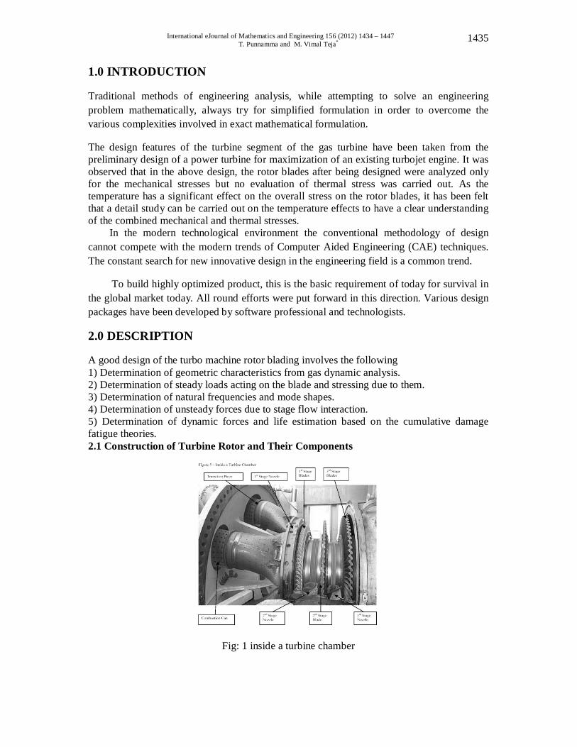
Fig: 2 Turbine’s Second Stage Blades
2.2 FINITE ELEMENT PROCEDURE
Discretize the Continuum Select Interpolation Functions Find the Element Properties Assemble the Element Properties to obtain the System Equations Impose the Boundary Conditions Solve the System Equations Make Additional Computations
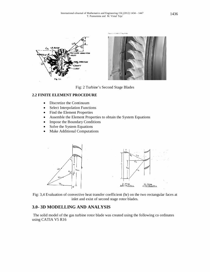
Fig: 3,4 Evaluation of convective heat transfer coefficient (hr) on the two rectangular faces at inlet and exist of second stage rotor blades.
3.0- 3D MODELLING AND ANALYSIS
The solid model of the gas turbine rotor blade was created using the following co ordinates using CATIA V5 R16
International eJournal of Mathematics and Engineering 156 (2012) 1434 – 1447 T. Punnamma and M. Vimal Teja*
1437
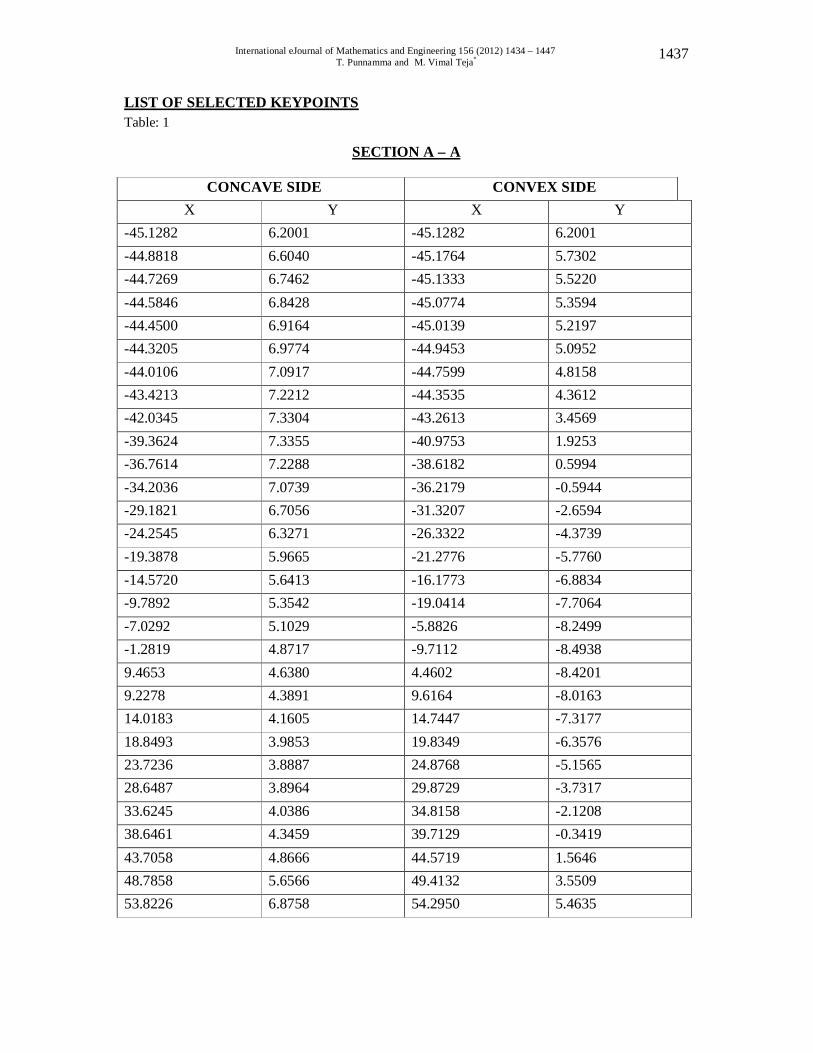
LIST OF SELECTED KEYPOINTS Table: 1
SECTION A – A
CONCAVE SIDE CONVEX SIDE X Y X Y
-45.1282 6.2001 -45.1282 6.2001 -44.8818 6.6040 -45.1764 5.7302 -44.7269 6.7462 -45.1333 5.5220 -44.5846 6.8428 -45.0774 5.3594 -44.4500 6.9164 -45.0139 5.2197 -44.3205 6.9774 -44.9453 5.0952 -44.0106 7.0917 -44.7599 4.8158 -43.4213 7.2212 -44.3535 4.3612 -42.0345 7.3304 -43.2613 3.4569 -39.3624 7.3355 -40.9753 1.9253 -36.7614 7.2288 -38.6182 0.5994 -34.2036 7.0739 -36.2179 -0.5944 -29.1821 6.7056 -31.3207 -2.6594 -24.2545 6.3271 -26.3322 -4.3739 -19.3878 5.9665 -21.2776 -5.7760 -14.5720 5.6413 -16.1773 -6.8834 -9.7892 5.3542 -19.0414 -7.7064 -7.0292 5.1029 -5.8826 -8.2499 -1.2819 4.8717 -9.7112 -8.4938 9.4653 4.6380 4.4602 -8.4201 9.2278 4.3891 9.6164 -8.0163 14.0183 4.1605 14.7447 -7.3177 18.8493 3.9853 19.8349 -6.3576 23.7236 3.8887 24.8768 -5.1565 28.6487 3.8964 29.8729 -3.7317 33.6245 4.0386 34.8158 -2.1208 38.6461 4.3459 39.7129 -0.3419 43.7058 4.8666 44.5719 1.5646 48.7858 5.6566 49.4132 3.5509 53.8226 6.8758 54.2950 5.4635

International eJournal of Mathematics and Engineering 156 (2012) 1434 – 1447 T. Punnamma and M. Vimal Teja*
1438
Table: 2
SECTION B - B
CONCAVE SIDE CONVEX SIDE X Y X Y
-44.5618 9.1237 -44.5618 9.1237 -44.3078 9.4894 -44.6227 8.6817
-44.1477 9.6139 -44.5897 8.4836 -44.0055 9.6952 -44.5389 8.3261
-43.8709 9.7587 -44.4805 8.1890
-43.7413 9.8069 -44.4170 8.0670 -43.4315 9.8933 -44.2443 7.9020
-42.8473 9.9771 -43.8607 7.3355 -41.4757 9.9898 -42.8168 6.4084
-38.8341 9.8146 -40.6197 4.8133 -36.2610 9.5352 -38.3489 3.4036
-33.7312 9.2126 -35.0274 2.1158 -28.7579 8.5115 -31.2826 -0.1651
-23.8658 7.7978 -26.4338 -2.1285 -19.0271 7.1044 -25.5062 -3.8075
-18.2265 6.4389 -14.5176 -5.2172 -10.4564 5.8090 -17.4783 -6.3652
-8.7015 5.2146 -5.3983 -7.2568 0.0432 4.6355 -1.2878 -7.8715
4.7879 4.0538 4.8456 -8.1966 9.5453 3.4519 8.9891 -8.2118
14.3281 2.8651 14.1800 -7.9527
19.1465 2.3241 19.2557 -7.4472 24.0132 1.8517 24.3586 -6.7110
28.9255 1.4681 29.4335 -5.7336 33.8938 1.2040 34.4805 -4.6685
38.9153 1.0871 39.4970 -3.3985
43.9826 1.1582 44.4906 -2.0091
49.0380 1.4783 49.4741 -0.5512 54.1807 2.1946 54.4855 0.8280

International eJournal of Mathematics and Engineering 156 (2012) 1434 – 1447 T. Punnamma and M. Vimal Teja*
1439

International eJournal of Mathematics and Engineering 156 (2012) 1434 – 1447 T. Punnamma and M. Vimal Teja*
1440
Table: 3
SECTION C – C
CONCAVE SIDE CONVEX SIDE
X Y X Y -39.6850 21.7754 -39.6850 21.7754 -39.4411` 21.9481 -39.7634 21.4859 -39.2963 21.9837 -39.7459 21.3360 -39.1643 21.9939 -39.7104 21.2115 -39.0423 21.9939 -39.6672 21.0947 -38.9255 21.9862 -39.6164 20.9906 -38.6486 21.9456 -39.4818 20.7416 -38.1279 21.8135 39.1719 20.2997 -36.9113 21.3690 38.3134 19.3192 -34.5669 20.3657 -36.4871 17.5006 -32.2783 19.3040 -34.5872 15.7861 -30.0203 18.2143 -32.6415 14.1402 -25.5524 16.0045 -29.6360 11.0119 -21.1226 13.7897 -25.5161 8.0569 -17.7132 11.5849 -80.2997 5.2629 -14.3139 9.3980 -25.9969 2.6187 -9.9197 7.2339 -16.6154 0.1194 -8.5230 5.0902 -7.1577 -2.2327 1.8738 2.9566 -2.6238 -4.4272 5.2680 0.8204 6.9837 -6.4541 9.6596 -1.3310 7.6675 -8.3007 19.0691 -3.4772 11.4148 -9.9847 19.4988 -5.6007 26.2128 -11.5240 22.9641 -7.6937 28.0515 -12.9286 27.4676 -9.7434 29.9283 -14.2021 32.0167 -11.7323 30.8356 -15.1097 36.6992 -13.6449 35.7657 -16.4567 41.2801 -15.4584 40.7111 -17.4650 46.0096 -17.1374 45.6692 -18.4353 50.8305 -18.5801 50.6146 -19.4640

International eJournal of Mathematics and Engineering 156 (2012) 1434 – 1447 T. Punnamma and M. Vimal Teja*
1441
Table: 4 SECTION D - D
CONCAVE SIDE CONVEX SIDE
X Y X Y -37.0078 25.9613 -37.0078 25.9613 -36.8071 26.0452 -37.0535 25.7505 -36.6827 26.0410 -37.0256 25.6261 -36.5684 26.0223 -36.9849 25.5194 -36.4617 25.9944 -36.9367 25.4178 -36.3601 25.9613 -36.8859 25.3238 -36.1112 25.8699 -36.7462 25.0977 -35.6438 25.6489 -36.4414 24.6812 -34.5389 25.0292 -35.6108 23.7160 -32.3952 23.7160 -33.8709 21.8821 -30.2895 23.3647 -32.0751 20.1143 -28.2016 20.9956 -31.2412 18.3921 -24.0614 18.2448 -26.4846 15.0546 -19.9390 15.4915 -22.6390 11.8364 -15.8217 12.7508 -18.7147 8.7198 -11.7069 10.0254 -14.7168 5.7074 -7.5844 7.3203 -19.6528 2.7889 -5.4569 4.6355 -8.5227 -0.0279 9.6731 1.9583 -4.3241 2.7432 4.8082 -0.8112 8.9431 -5.3442 2.9408 -3.3884 9.2814 -7.8257 16.0886 -6.0554 10.6782 -10.2032 17.2542 -8.7020 15.1308 -12.4790 21.4452 -11.3259 19.6266 -14.6660 25.6667 -13.9167 24.1656 -16.7665 29.9263 -16.4643 28.7376 -18.7960 34.2265 -18.9586 33.3426 -20.7565 38.5775 -21.3868 37.9679 -22.6720 42.9895 -23.7236 42.6060 -24.5567 47.4853 -25.9105 47.2338 -26.4770

International eJournal of Mathematics and Engineering 156 (2012) 1434 – 1447 T. Punnamma and M. Vimal Teja*
1442
Table: 5
SECTION E - E
CONCAVE SIDE CONVEX SIDE X Y X Y
-35.9969 27.3177 -35.9969 27.3177 -35.8191 27.3685 -36.0248 27.1348 -35.7022 27.3507 -35.9918 27.0205 -35.5981 27.3202 -35.9461 26.9215 -35.4965 27.2821 -35.8953 26.8249 -35.4000 27.2415 -35.8419 26.7360 -35.1663 27.1297 -35.6997 26.5176 -34.7218 26.8808 -35.3924 26.1112 -33.6626 26.2001 -34.5654 25.1562 -31.6001 24.7802 -32.8447 23.3223 -29.5681 23.3299 -31.0744 21.5443 -27.5514 21.8669 -29.2735 19.8018 -23.5407 18.9332 -25.5956 16.4059 -19.5402 16.0020 -24.8389 13.1039 -15.5423 13.0835 -19.0137 9.8908 -14.5418 10.1803 -14.1224 6.7615 -9.5311 7.2974 -10.1702 3.7109 -5.5154 4.4323 -8.1620 0.7442 4.5105 1.5799 -6.0904 -2.1387 9.5390 -1.2649 2.0447 -4.9276 8.5725 -4.1097 6.2433 -7.6175
12.6162 -6.9418 13.4978 -10.2210 16.6776 -9.7587 14.8006 -12.7432 20.7645 -12.5476 19.1465 -15.1827 24.8793 -15.3111 23.5356 -17.5641 29.0271 -18.0340 27.9578 -19.8786 33.2105 -20.7137 32.4079 -22.4151 37.4421 -23.3350 36.8833 -24.3535 41.7271 -25.8826 41.3741 -26.5430 46.0882 -28.3058 45.8546 -28.7579

International eJournal of Mathematics and Engineering 156 (2012) 1434 – 1447 T. Punnamma and M. Vimal Teja*
1443
Using splines and multisection solid different areas were generated which was shown in figures.
Fig: 5 Blade profile section A-A Fig : 6. Blade profile section A-A and B-B
Fig:7 Blade profile section A-A ,B-B and C-C Fig:8 Blade profile section A-A ,B-B ,C-C and D-D
Fig: 9 Blade profile section A-A, B-B, C-C , Fig:10 Blade profile with sections and
D-D and E-E without root

International eJournal of Mathematics and Engineering 156 (2012) 1434 – 1447 T. Punnamma and M. Vimal Teja*
1444
Fig .11 Blade profile without root Fig .12 Blade profile with root 4.0 OVERVIEW OF STEPS IN MODAL ANALYSIS
The procedure for modal analysis consist of four main steps 1) Build the model 2) Apply loads and obtain the solution 3) Expand the modes 4) Review the results
Table: 6 Natural frequencies Modal Analysis
Sr.No Time/Freq. Load step Sub step Cumulative 1 12.109 1 1 1 2 29.245 1 2 2 3 46.862 1 3 3
5.0 RESULTS AND DISCUSSIONS
Fig.13 Solid modal of gas turbine blade Fig.14 Finite Element model Free Mesh

International eJournal of Mathematics and Engineering 156 (2012) 1434 – 1447 T. Punnamma and M. Vimal Teja*
1445
Fig. 15 Von mises stress of gas turbine Fig. 16Displacement Vector sum USUM
rotor blade
Fig.17 model with thermal loads Fig .18 Temperature distribution
Fig. 19 Thermal displacements Fig .20 Thermal stress

International eJournal of Mathematics and Engineering 156 (2012) 1434 – 1447 T. Punnamma and M. Vimal Teja*
1446
Fig .21 Thermal displacements after Fig .22 Modal 1
applying forces
Fig .23 Modal 2 Fig .24 Modal 3 5.1 THERMAL ANALYSIS From the post processing, the temperature variation obtained as shown in fig. From figure, it is observed that the temperature variations from leading edge to the trailing edge on the blade profile is varying from 839.5310C to 735.2070C at the tip of the blade and the variation is linear along the path from both inside and outside of the blade. Considerable changes are not observed from the first 6 mm length from the leading edge and from there to next 36 mm length of blade the temperature is gradually decreasing and reaching to a temperature of 781.5480C and for another 4 mm length it is almost constant. Wherever maximum curvature is occurring the temperature variation is less. The temperature decreases gradually along X-direction. The thermal stresses are obtained as shown in the fig from figure, it is observed that the maximum thermal stress is 1165. The maximum thermal stress is less than the yield strength value i.e. 1450.so, based on these values For the thermal analysis the design of turbine blade is safe. 5.2 STRUCTARAL ANALYSIS The von misses stresses are obtained as shown in the fig from figure, it is observed that the maximum von misses stress is 472.576.this value is less than the yield strength value i.e.650. The maximum deformation in USM Overall direction is 1.765mm.based on these values For the structural analysis the design of turbine blade is safe based on the strength criteria and rigidity criteria..
International eJournal of Mathematics and Engineering 156 (2012) 1434 – 1447 T. Punnamma and M. Vimal Teja*
1447
5.3 MODAL ANALYSIS Maximum deformation of gas turbine rotor blade at 12.109HZ for first Sub step is 3.077mm Maximum deformation of gas turbine rotor blade at 29.245HZ for second Sub step is 2.795mm. Maximum deformation of gas turbine rotor blade at 46.862HZ for third Sub step is 5.189mm 6.0 CONCLUSIONS The temperature has a significant effect on the overall stresses in the turbine blades. Maximum elongations and temperatures are observed at the blade tip section and
minimum elongation and temperature variations at the root of the blade. Temperature distribution is almost uniform at the maximum curvature region along
blade profile. Maximum stress induced is within safe limit. Maximum thermal stresses are setup when the temperature difference is maximum
from outside to inside. Maximum stresses are observed at the root of the turbine blade and upper surface
along the blade roots. Elongations in X-direction are observed only at the blade region in the along the blade
length and elongation in Y-direction are gradually varying from different sections along the rotor axis.
It could be concluded that these contour maps and profiles enables us to ascertain the areas of rotor blades that are vulnerable for failure
Maximum thermal stresses are setup when the temperature difference is maximum from outside to inside.
Maximum stresses are observed at the root of the turbine blade and upper surface along the blade roots.
Elongations in X-direction are observed only at the blade region in the along the blade length and elongation in Y-direction are gradually varying from different sections along the rotor axis.
It could be concluded that these contour maps and profiles enables us to ascertain the areas of rotor blades that are vulnerable for failure
7.0 REFERENCES 1) S.S.Rao,”The Finite Element method in Engineering”, BH Publications New Delhi,
3rd Edition, 1999. 2) O.C.Zeinkiewicz,”The Finite Element method in Engineering Science”, Tata McGraw
Hill, 2nd Edition, 1992. 3) T.R.Chandrupatla, Belegundu A.D.,”Finite Element Engineering”, Prentice Hall of
India Ltd, 2001. 4) O.P.Gupta,”Finite and Boundary element methods in Engineering”, Oxford and IBH
publishing company Pvt.Ltd.New Delhi, 1999. 5) V.Ramamurti,” Computer Aided Design in Mechanical Engineering”, Tata McGraw
Hill publishing company Ltd.New Delhi, 1987. 6) Jean-Claude Sabonnadiere and Jean-Louis Coulomb,” Finite Element method in
CAD”, North Oxford University, 1987. 7) C.S.Krishnamoorthy,”Finite Element Analysis, Theory and Programming, 2nd
edition, Tata McGraw Hill publishing company Ltd.New Delhi, 2002. 8) P.Ravinder Reddy,”CADA Course Book”, AICTE-ISTE sponsored programmer,
August 1999.
Related Documents