3iDCOCA:A?111 83 AUTOSINKRON GENERATOR 3 PHASE MENGGUNAKAN TEKNOLOGI FUZZY LOGIC CONTROL NLX 222P 89 0.-1 1998 TUGAS AKHIR Oleh : SYAIFUL SYAHRI 2294.100.532 JURUSAN TEKNIK ELEKTRO FAKULTAS TEKNOLOGI INDUSTRI P 1 '. . (. I. E) . . '; K A A N ,;. ... .... INSTITUT TEKNOLOGI SEPULUH NOPEMBER SURABAYA 1998

Welcome message from author
This document is posted to help you gain knowledge. Please leave a comment to let me know what you think about it! Share it to your friends and learn new things together.
Transcript

3iDCOCA:A?111 83
AUTOSINKRON GENERATOR 3 PHASE MENGGUNAKAN TEKNOLOGI FUZZY LOGIC
CONTROL NLX 222P
R~e ro~) 89 ~~~ 0.-1
1998
TUGAS AKHIR
Oleh :
SYAIFUL SYAHRI 2294.100.532
JURUSAN TEKNIK ELEKTRO FAKULTAS TEKNOLOGI INDUSTRI
P 1'. . (. I. E) . . '; K A A N ,;. ... .... ~ ~
INSTITUT TEKNOLOGI SEPULUH NOPEMBER SURABAYA
1998

AUTOSINKRON GENERATOR 3 PHASE MENGGUNAKAN TEKNOLOGI FUZZY LOGIC
CONTROL NLX 222P
TUGAS AKlllR Diajukan Guna Memenuhi Sebagian Persyaratan
Untuk Memperoleh Gelar Sarjana Teknik Elektro
Pad a
Bidang Studi Elektronika
Jurusan Teknik Elektro
Fakultas Teknologi lndustri
lnstitut Teknologi Sepuluh Nopember
Surabaya
Mengetahui I Menyetujui
...---------( Ir. H. MOCH. HEROE )
NIP : 130 368 609
SURABAYA Maret 1998


ABSTRAK
Kerja paralel Generator- PLN dimaksudkan untuk mendapatkan daya yang lebih besar. Sumber tegangan AC 3 Phase ( generator ) dapat diparalel jika memenuhi persyaratan antara lain : Urutan phase R, S, T antara sumber hams sama, Tegangan hams sama, Frekuensi hams sama, Phase hams sama. Dalam perencanaan ini PLN sebagai sumber tegangan utama akan di paralel dengan generator sinkron yang digerakkan oleh motor DC.
Fuzzy Logic Controller NLX 222P mengatur tegangan yang dibangkitkan oleh generator sinkron dengan menambah atau mengurangi ams eksitasi yang masuk ke belitan medan. Demikianjuga dengan frekuensi yang dibangkitkan oleh generator datur oleh FLC NLX 222P dengan menambah atau mengurangi arus medan sehingga didapatkan putaran yang diinginkan. Dengan selisih tegangan , selisih frekuensi dan beda phase sebagai input Fuzzy, maka fuzzy akan menyamakan parameter tersebut sehingga didapatkan tegangan, frekuensi, dan phase yang sama dan proses sinkron atau kerja paralel secara otomatis akan bekerja.
Ill

KATA PENGANTAR
Karni ucapkan puji syukur kehadlirat ALLAH SUBHANNAALLAHU
WATA'ALA atas segala rahrnat dan ridlonya yang diberikan kepada kita sernua
sehingga karni dapat rnenyelesaikan Tugas Akhir yang berjudul :
AUTO SINKRON GENERA TOR 3 PHASE MENGGUNAKAN TEKNOLOGI FUZZY LOGIC CONTROL NLX 222P
Tugas Akhir ini rncrupakan salah satu syarat untuk dapat rnenyelesaikan
pcndidikan di Jurusan Tcknik Elcktro Fakultas Teknologi Industri Institut
Tcknologi Scpuluh Nopcmbcr Surabaya.
Tugas Akhir ini dibuat berdasarkan ilrnu yang karni peroleh dari Bapak
dosen yang dengan keikhlasan rnernberikan kepada karni, buku - buku literatur,
serta petunjuk dari ternan- ternan.
Dalarn kesernpatan ini karni juga rneucapkan terirna kasih kepada:
1. Bapak dan Ibu saya yang telah rnernbesarkan dan rnendidik karni
2. Bapak Ir.H.MOCHAMMAD HEROE, selaku Dosen Wali serta juga
Pernbirnbing yang senantiasa rnendidik karni
3. Bapak Ir. SOETIKNO, sclaku Koordinator Bidang Studi Elektronika
4. Bapak Jr. TEGUH YUWONO, selaku Ketua Jurusan Teknik Elektro
5. Kakak-ku yang telah rnernberikan bantuan dan dorongan
6. Seluruh stafDosen dan Karyawan Jurusan Teknik Elektro- ITS
7. Ternan- ternan penghuni LAB TTL Jurusan Teknik Elektro- ITS
lV

J
8. Ternan - teman penghuni LAB ELKA, MEDIKA, MIKRO, R & D Bidang
Studi Elektronika - ITS
9. Ternan- Teman antara lain : Rindu, Lolok, Gatot, Rudi, Cucuk yang telah
banyak rnembantu saya.
Karni berharap kiranya Hasil karaya Tugas Akhir ini dapat dimanfaatkan
bagi siapa saja yang rnemerlukan untuk digunakan dalam kebaikan.
Surabaya, Maret 1998
Penulis


DAFTAR lSI
JUDUL
LEMBAR PENGESAHAN
ABSTRAK
KA TA PENGANTAR
DAFTARISI
DAFTAR TABEL
DAFTAR GAMBAR
BABIPENDAHULUAN
1.1 Latar Belakang
1.2 Perrnasalahan
1.3 Pembatasan Masalah
1.4 Tujuan
1.5 Metodologi
1.6 Sistematika
1. 7 Relevansi
BAB ll TEORI PENUNJANG
2. 1 Alternator ( Generator AC )
2.1.1 Alternator Tanpa Beban
2.1.2 Karakteristik Hubung Singkat
Vl
Jl
Ill
IV
VI
X
XI
2
2
3
3
4
4
5
5
6
7

2.1.3 Reaktansi Sinkron
2.1.4 Pengaturan Tegangan
2.2 Motor DC
2.2.1 Prinsip Dasar
2.2.2 Jenis- Jenis Motot DC
2.2.3 Karakteristik Motor DC
2.2.4 Pengaturan Kecepatan Motor DC Shunt
2.3 Kerja Paralel Generator
2.4 Operational Amplifier
2.4.1 Inverting Amplifier
2.4.2 Non Inverting Amplifier
2.4 .3 Komparator
BAB ill TEORI LOGIKA FUZZY
3. 1 Pendahuluan
3.2 Fungsi Membership
3.3 Struktur Dasar Pengaturan Logika Fuzzy
3.3.1 Fuzzifikasi ( Fuzzification)
3.3.2 Pengambilan Keputusan (Rule Evaluation)
3.3.3 Defuzzifikasi ( Defuzzification)
3.4 Chip Fuzzy NLX 222 P
3. 4. 1 Arsitektur NLX 222 P
Vll
8
9
12
13
14
17
22
24
26
28
31
34
36
36
37
41
41
42
42
43
46

3.4.2 Membership Function
3 .4. 3 Variabel Fuzzy
3.4.4 Rule
3.4.5 Floating Membership Function
3.4.6 Operational Device
3.4.7 Organisai Memory
3.4.8 Timing
BAB IV PERENCANAAN ALAT
4.1 Perencanaan Perengkat Keras
4.1.1 Sistem Autosinkron Generator- PLN
4.1.2 Rangkaian Sensor Tegangan
4.1 .3 Rangkaian Sensor Frekuensi
4. 1. 4 Rangkaian Sensor Phase
4.1.5 Kontroler
4.1.6 Rangkaian Driver
4. 2 Perencanaan Perangkat Lunak
BAB V PENGUJIAN DAN PENGUKURAN
5. 1 Pengukuran T egangan Generator
5.2 Pengukuran Frekuensi Generator
V111
47
4.8
49
50
51
53
54
59
59
60
63
64
65
66
68
69
76
76
77

BAB VI PENUTUP
6. 1 Kesimpulan
6.2 Saran
DAFTAR PUSTAKA
LAMP IRAN
A Rangkaian Sensor Tegangan
B. Rangkaian Sensor Frekuensi
C. Rangkaian Sensor Phase
D. Rangkaian FLC NLX 222P
E. Rangkaian Driver Eksitasi
F . Rangkaian Driver Speed
G. Data Sheet NLX 222P
lX
81
81
81
82


DAFTAR TABEL
Tabel 3.1 Organisasi Memori 54
5.1 Hasil Pengukuran Tegangan Generator 76
5.3 Hasil Pengukuran Frekuensi Generator 78
5.4 Hasil Pengukuran Generator Beban Induktif 79
5.5 Hasil Pengukuran Generator Beban Resistif 80
X


DAFTAR GAMBAR
Gambar 1.1 Kumparan Jangkar di Dalam Medan Magnet
1.2 Stator dan Rotor
1. 3 Kurva Pemagnetan
1.4 Karakteristik Tanpa Beban dan Hubung Singkat
1.5 Karakteristik Faktor Kerja Nol
1.6 Power Faktor Legging, 1 , dan Leading
1.7 Unity , Legging, Leading
1.8 Motor DC 4 Kutub
1.9 Rangkaian Ekivalen Motor DC Seri
1.10 Rangkaian Ekivalen Motor DC Shunt
1. 11 Rangkaian Ekivalen Motor DC Compound
1.12 Karakteristik Motor DC Seri
1.13 Karakteristik Motor DC Shunt
1.14 Karakteristik Motor DC Compound
1.15 Pengaturan Kecepatan Medan Shunt
1 . 16 Pengaturan Kecepatan Tahanan J angkar
1.17 Pengaturan Kecepatan Dengan Tegangan
1.18 Kerja Paralel Generator dan Jala - Jala
1.19 Notasi Operational Amplifier
1.20 Polaritas Output terhadap Input
XI
5
6
7
8
9
10
11
14
15
16
17
19
20
22
23
23
24
25
26
28

4.1 Blok Diagram Autosinkron 61
4.2 Sensor Tegangan 63
4.3 Rangkaian Diferensial Amplifier 64
4.4 Rangkaian Sensor Frekuensi 65
4.5 Rangkaian Sensor Phase 66
4.6 Rangkaian Proteksi dan Buffer 67
4.7 Rangkaian Driver Eksitasi 68
4.8 Rangkaian Driver Kecepatan 69
4.9 Hubungan Input Output NLX 222P 71
4.10 Variabel Fuzzy Untuk Antecendent Voltage 72
4.11 Variabel Fuzzy Untuk Antecendent Freq 72
4.12 Variabel Fuzzy Untuk Antecendent Phase 73
4.13 Variabel Fuzzy Untuk Antecendent Relay 73
4.14 Variabel Fuzzy Untuk Antecendent FreqOK 74
4.15 Diagram Alir Urutan Fuzzy 75
5.1 Tegangan Generator Terhadap Waktu 77
5.2 Frekuensi Generator Terhadaqp Waktu 79
Xlll

[g)~[g)~
[?[[N][D~[h1(\J}l\\JJ~[N]

..
1. 1 Latar Belakang
BABI
PENDAHULUAN
Generator sebagai penghasil energi listrik, pada saat ini semakin banyak di
gunakan pada industri sebagai sumber energi listrik untuk mendukung
kelangsungan proses produksi . Salah satu keuntungan penggunaan generator
yaitu kapasitas daya, yang tersedia dapat disesuaikan dengan beban yang
terpakai, serta kcmudahan mendapatkannya. Untuk mendapatkan daya listrik
yang dikehendaki dapat dilakukan dengan mempararel dua buah .. generator
untuk dioperasikan secara bersama - sama. Syarat - syarat yang harus
dipenuhi untuk kerja paralel generator adalah : tegangan harus sama ,
frekuensi harus sama , beda phase harus sama.
Dengan berkembangnya sistim kontrol elektronika, maka proses kerja
paralel generator dapat dilakukan secara otomatis dalam waktu yang relatif
Iebih cepat , dengan tingkat akurasi yang tinggi serta hasil yang lebih baik .
Dengan menggunakan microcontroler proses kerja paralel dapat dilakukan
dengan hasil yang Iebih baik
Fuzzy logic merupakan perkembangan dari mikrokontroler yang
mempunyai input data yang acak dan sistim non Iinier untuk mendapatkan
Iaju kontrol yang handal , sehingga penggunaan Fuzzy logic pada proses kerja
paralel mempunyai nilai tambah yang lebih yaitu efisiensi tinggi, performansi

2
yang lebih baik serta penguasaan teknologi barn. Dalam kerja paralel fuzzy
logic digunakan pada proses pengendali input , sehingga didapatkan output
dengan hasil yang maksimum.
1.2 Permasalahan
Pada proses sinkronisasi generator ada tiga parameter yang harus dipenuhi
agar generator tersebut dapat diparalel yaitu tegangan, frekwensi dan beda
phase yang sama antara generator satu dengan generator lainnya. Dengan
demikian pada proses ini diperlukan sistim pengaturan tegangan, frekuensi
serta beda phase yang lebih cepat dengan tingkat akurasi yang tinggi agar
tidak menyebabkan kerusakan pada salah satu genertor akibat kesalahan
proses sinkronisasi. Dengan menggunakan Fuzzy micro controller proses
sinkronisasi tersebut dapat dilakukan dalam waktu yang cepat dan akurasi
yang tinggi.
1.3 Batasan Masalah
~.
Dalam tugas akhir ini akan disinkronkan antara sumber dari PLN sebagai
sumber utama dengan generator sebagai sumber cadangan. Pengaturan
tegangan generator dilakukan dengan mengatur penguatannya , sedangkan
frekwensi diatur melalui putaran penggeraknya berupa motor de.
Proses sinkronisasi dilakukan oleh Fuzzy sebagai pusat pengendali dari
sistem ini dengan cara membandingkan parameter generator dengan
parameter PLN untuk didapatkan kesamaan tegangan , frekwensi dan beda
phase. Jika ketiga parameter belum dicapai kesamaan, maka output fuzzy

3
akan memberikan pengaturan pada genset dan penggerak mula berupa motor
de.
1.4 Tujuan
Tujuan dari perencanaan dan pembuatan alat AUTOSINKRON
GENERA TOR 3 PHASE DENGAN MENGGUNAKAN FUZZY LOGIC tm
adalah:
• Mempelajari dan mengimplementasikan teori fuzzy logic controller pada
pengaturan kerja paralel generator.
• Merencanakan dan membuat kontroler kerja paralel generator dengan
menggunakan fuzzy microcontroller NLX 222 P.
1.5 Metodologi
Metodologi yang dilakukan dalam perencanaan dan pembuatan alat ini
adalah sebagai barikut :
• Studi literatur tentang teori generator ac, teori kerja paralel generator
serta teori logika fuzzy NLX 222 P.
• Merencanakan sistim atau blok diagram dari fungsi alat tersebut
• Mengimplementasikan dari masing - masing blok kedalam perencanaan
perangkat keras sehingga berfungsi sebagaimana mestinya.
• Merencanakan pembuatan perangkat lunak berdasarkan fungsi dari alat
terse but.
• Melakukan pengukuran dan penguj ian terhadap fungsi dari masmg -
masing blok.

4
• Melakukan pengukuran dan pengujian terhadap fungsi dari seluruh sistim
yang ada seperti yang direncanakan.
1.6 Sistematika
Sistematika pembahasan pada tugas akhir ini adalah sebagai berikut:
Bab I : merupakan pendahuluan dari laporan tugas akhir ini.
Bab II : membahas teori penunjang yang meliputi teori dasar generator
AC, motor DC, kerja paralel serta teori dasar oparation amplifier.
Bab III : membahas secara luas tentang teori dasar logika fuzzy NLX 222 P.
Bab IV : mcmbahas tcntang pcrencanaan perangkat kcras dan perangkat
lunak hingga rcalisasi pembuatan alat tersebut.
Bab Y : Pengukuran dan pengujian alat guna melengkapi bukti kebenaran
dari perencanaan alat tersebut.
Bab VI : merupakan penutup dari seluruh rangkaian laporan yang berisikan
kesimpulan serta saran- saran untuk perkembangan lebih lanjut.
1. 7 Relevansi
Dari hasil perencanaan dan pembuatan alat dalam tugas akhir ini
diharapkan dapat memberikan sumbangan pemikiran dan karya ilmiah
kepada teknik elektro institut teknologi sepuluh nopember surabaya.

--·· • r. ~~ i ~ .
j ; 00 :~ ~ "" ~,..._
~ ::::; :§

BABII
TEORI PENUNJANG
2.1 Alternator (Generator Sinkron)
Generator adalah alat yang berfungsi untuk merubah energi mekanis
menjadi energi listrik yang prinsip kerjanya berdasarkan hukum faraday. Jika
suatu penghantar bergerak dalam medan magnet dengan memotong flux
rnegnet terscbut, rnaka dalarn pcnghantar akan terinduksi suatu tegangan.
Begitu juga jika flux yang bcrubah memotong suatu penghantar yang tetap.
Pada gambar 1.1 di bawah ini menunjukkan proses tirnbu1nya tegangan pada
sebuah penghantar yang diputar di dalam daerah medan magnet. Generator
sinkron mernpunyai kumparan jangkar pada stator dan kumparan medan pada
rotor. Kumparan stator terdiri dari tiga buah belitan yang dihubungkan tiga
phase dengan beda sudut sebesar 120 °.
Rotasi
Gnmbnr 1.1 1>
Kumparan jangkar di dalam medan magnet
t) Gupta J.B Electrical Machines-1, Katson Publishing House, 1980 P.4
5

6
- ' -· -1..
(a) (b)
Gambar 1.22>
(a) Stator (b) Rotor
2.1.1 Alternator Tanpa Behan
Dengan memutar alternator pada kecepatan sinkron dan rotor
diberi arus medan ( Ir) , tegangan ( E0 ) akan terinduksi pada kumparan
jangkar stator sebesar:
Eo=cn<I> . .. . ..... . .. ..... .. .. ... ........... (i)
dimana : c = konstanta mesin n = putaran sinkron
<I> = fluks yang dihasilkan oleh Ir
Dalam keadaan tanpa beban arus jangkar tidak tidak mengalir pada
stator , oleh karena itu tidak terdapat pengaruh reaksi jangkar. Fluks
hanya dihasilkan oleh arus medan ( Ir ). Apabila arus medan ( Ir )
diubah - ubah harganya , akan diperoleh harga E0 seperti yang terlihat
pada kurva pemagnetan merupakan garis lurus.
2> -----, Manual Self Regulating Brushless Alternator, A VK, P.28-29

v
a b
Gambar 1.33>
Kurva pemagnetan
2.1.2 Karakteristik Hubung Singkat
7
A
Karaktaristik hubung singkat generator 3 phase digambarkan
dengan fungsi arus Isc = f ( ie ), pada frekuensi ( f ) dan tegangan ( V )
konstan. Karena resultante fluks ~s dari mesin pada saat hubung singkat
hanya menghasilkan emf E8 yang kecil untuk menghasilkan drop
tegangan ra . I + J Xap • I rangkaian magnet dari sistim tidak saturasi
dan karenanya karakteristik hubung singkat seperti garis lurus yahg
mulai melengkung saat mencapai arus rating In. Gambar 1.4
menunjukkan grafik arus hubung singkat yang diperoleh dari hubungan
antara Arus jangkar terhadap tegangan tanpa beban. Karakteristik
hubung singkat di perlukan untuk menentukan harga reaktans sinkron
yang nilainya ditentukan oleh perbandingan antara Tegangan tanpa
beban dengan anis hubung singkat.
3> Zuhal, Dasar Tenaga Listrik, ITB, 1986 P .S2

c G a c G a ~ 6
3
Arnporo modMn
Gambar 1.44>
(a) Karakteristik Tanpa beban (b) Karakteristik llubung Singkat
2.1.3 ncn ktn ns Sin kron
8
Dari karakteristik tanpa beban Eo sebagai fungsi arus medan ( Ir },
maka jika digambar dalam satu grafik akan didapat suatu bentuk kurva.
Hubungan ini menghasilkan kurva pemagnetan dan dari kurva ini harga
yang akan dipakai adalah harga liniernya unsaturated. Harga linier yang
merupakan garis lurus adalah kelebihan arus medan pada keadaan
jenuh sebenarnya dikompensasi oleh adanya reaksi jangkar. Jadi harga
reaktans sinkron adalah : Xs = Eo . Seperti diuraikan diatas reaktans lhs
sinkron Xs di peroleh dari harga liniernya atau dalam keadaan tidak
jenuh unsaturated .
4> Ibid, P. 54

9
V P-n
v
v,
0 .. ••
Gambar 1.55> ( a ) karakteristik tanpa beban ( b ) karakteristik faktor kerja nol
Karena itu hasil yang diperoleh kurang teliti dan hanya dapat dipakai
untuk perhitungan kasar. Untuk memperoleh harga Reaktans yang lebih
tepat digunakan segitiga potier. Segitiga potier ditentukan dari
karakteristik tanpa beban dengan karakteristik faktor kerja nol sebuah
mesin. Seperti terlihat pada gambar 1.5 yaitu grafik segitiga potier.
2.1.4 Pengaturan Tegangan
Terjadinya perbedaan antara tegangan terminal V dalam keadaan
berbeban dengan tegangan E0 pada saat tidak berbeban, dipengaruhi
selain oleh faktor kerja juga oleh besarnya arus jangkar yang mengalir.
Dengan memperhatikan perubahan tegangan V untuk faktor kerja
berbeda - beda seperti pada gambar 1.6 , karakteristik tegangan
terminal V terhadap arus jangkar I dapat digambarkan dibawah ini.
S) Ibid, P.54

10
(a) E
(b)
(c)
Gambar 1.66>
( a ) Power factor legging ( b ) Power factor 1 ( c )Power factor leading
Pengaturan tegangan adalah perubahan tegangan terminal alternator
antara keadaan beban not dengan beban penuh. Hal ini dinyatakan
sebagai berikut :
Eo-V Pengaturan tegangan = V ..................... ( ii )
Untuk mendapatkan output tegangan dari generator agar tetap
setabil hal ini dapat diatur dengan diketahui lebih dulu harga tahanan
jangkar R8 , karaktersitik beban not, dan karakteristik hubung singkat.
Sedangkan untuk menentukan pengaturan tegangan tersebut ada tiga
cara yaitu:
6> Ibid, P 57

11
1. lmpcdansi sinkron atau mctodc gaya gerak listrik:
Pengaturan tegangan dengan menggunakan metode impedansi
sinkron ada syarat - syarat yang harus dipenuhi yaitu :
• Menentukan harga impedansi sinkron dari karakteristik beban
no! dan karakteristik hubung singkat.
• menentukan harga Xs atau reaktans sinkron seperti talah
diuraikan sebelumnya.
• Menentukan harga tegangan dalam E0.
• Menentukan harga pengaturan tegangan.
2. Metode ampere lilitan atau metode gaya gcrak magnet.
Pada cara ini reaktans bocor X. diabaikan dan reaktansi jangkar
diperhitungkan. Ampere lilitan yang diperlukan untuk
membangkitkan tegangan V pada beban penuh adalah jumlah vektor
adalah sebagai berikut
E
IXs
IRa
(a) (b) (c)
Gambar 1.771
( a ) ~nity ( b ) legging (c) leading
71 Ibid, P.59

12
V adalah tegangan terminal yang jika dijumlahkan dengan
tegangan jatuh Ir. akan menghasilkan Fe. Pada pengujian hubung
singkat arus medan disesuaikan sampai keadaan arus nominal
dicapai, yang dalam hal ini adalah sebesar F1• Kemudian ditentukan
harga F 2 untuk mendapatkan E0• Ditentukan pula harga prosentase
pengaturan tegangan :
Eo-V
v X 100%
3. Mctodc faktor daya nol atau potier.
Mctodc ini didasarkan atas pemisahan dari reaktans bocor, rugi
jangkar dan efek - efek reaksi jangkar. Metode ini memerlukan data -
data percobaan :
(i) Kurva beban nol.
(ii) Kurva power faktor not beban penuh.
2.2 Motor DC
Pada prinsipnya mesin listrik dapat berlaku sebagai motor maupun sebagai
generator. Perbedaannya terletak pada konversi dayanya. Generator adalah
suatu mesin listrik yang mengubah daya masuk mekanik menjadi daya keluar
listrik, sedangkan sebaliknya motor mengubah daya masuk listrik menjadi
daya keluar mekanik.
Motor de terdiri dari kumparan medan pada stator dan kumparan jangkar
pada stator. Kumparan terdiri dari beberapa belitan yang dihubungkan satu

13
dengan yang lainnya sehungga setiap kumparan menggelung ·kembali ke sisi
kumparan berikutnya, maka hubungan ini disebut dengan belitan gelung.
Sedangkan pada kumparan yang hubungan antara ujung kumparan yang satu
dengan kumparan yang lainnya berbentuk gelombang maka jenis kumparan
ini disebut belitan gelombang.
2.2.1 Prinsip Dasar
Jika sebuah arus dialirkan pada pada sebuah penghantar yang
berada di dalam medan magnet , maka pada penghantar tersebut akan
timbul gaya mekamis yang arah putarannya sesuai dengan prinsip
tangan kiri fleming sehingga besarnya gaya pada konduktor tersebut
adalah:
F = B I l ...................................... (tn)
Dimana : F = Gaya medan magnet ( newton )
B = Kuat medan magnet ( wb/m2 )
I= Panjang penghantar (meter)
Ketika motor dihubungkan dengan sumber tegangan de, maka arus
akan mengalir melalui sikat - sikat dan komutator ke dalam kumparan
jangkar. Pada saat arus mengalir melalui komutator , arus de tersebut
dirubah menjadi arus ae sehingga rotor yang berada didalam kutub akan
berputar sesuai dengan prinsip tangan kiri fleming.

Gambar 1.881
Motor de 4 kutub
14
Pada gambar diatas merupakan motor de empat kutub , ketika kumparan
jangkar pada rotor dialiri arus de, maka arah arus dalam kumparan
jangkar keluar dibawah kutub N dan masuk dibawah kutub S demikian
seterusnya untuk kutub - kutub berikutnya.
2.2.2 Jenis - jenis motor de
Semua jenis motor de selalu memerlukan eksitasi dari sumber luar
oleh karena itu motor de selalu dilengkapi dengan penguat atau eksitasi.
Sehingga jenis - jenis motor de didasarkan pada penguatan medannya.
Jenis- jenis motor de ada 3 ( tiga) maeam yaitu:
1. Motor de seri
Adalah motor dengan kumparan medan dihubungkan seri dengan
kumparan jangkar sehingga dalam penggambaran pada rangkaian
ekivalen arus motor melalui kumparan stator menuju ke kumparan
jangkar. Sperti pada gambar di bawah ini.
81 Gupty, J.B, Katson Publishing House, 1980, P.113

....... __________ __
Rs
+ +
v
Gambar 1.99)
Rangkaian Ekivalen Motor DC Seri
Besamya emf Ia wan yang dibangkitkan sebesar :
15
Eb = V-I . (Ra-t- Rs ) .............. ....... ......... ( iv)
Dimana: Eb =EMF lawan I back emf (Volt)
V = Sumber tegangan ( Volt)
I = Arus yang mengalir ( Amper)
Ra = Tahananjangkar ( n)
Rs = Tahanan seri ( Q )
Maka daya yang diperlukan sebesar:
P = V I - f ( Ra + Rs )
= I [ V - I ( Ra + Rs ) ] = Eb . I
2 Motor de shunt
Adalah suatu motor yang mempunyai kumparan medan yang
terhubung paralel dengan kumparan jangkar, sehingga arus yang
9l Ibid, P. 116

to) Ibid, P 117
16
diberikan oleh sumber arus di paralel ke kumparan medan dan
kumparanjangkar. Seperti terlihat pada gambar berikut ini.
Besamya arus line yang mengalir adalah :
I L = I a + Ish ......... .. . .. ...... ... .... ... ........ .... . ( V)
Dimana : IL = Arus line ( ampere )
Ia = Arus jangkar ( ampere )
Ish = Arus medan shunt ( ampere )
v Ish= Rsh .. . ...... .... ........ ... ....... ... ... ...... . (vi)
EMF lawan , Eb = V - la . Ra
Sehingga daya yang diperlukan sebesar :
? = V ( lr_ - Ish) - Ia- . Ra
= V . I a - la 2 Ra = la ( V - la . Ra )
+ +
v
Gambar 1.1010)
Rangkaian Ekivalen Motor de shunt

17
3. Motor de Compound
Adalah motor de yang mempunyai dua buah kumparan medan
yaitu penggabungan antara medan seri dengan medan shunt. Motor
de compound ada dua buah type yaitu : motor de compound
comulative dan motor de compound differential.
Motor de compound comulative adalah belitan kumparan sen
searah dengan belitan kumparan shunt. Sehingga fluks medan seri
memperkuat fluks medan shunt. Motor de compound differential
belitan kumparan seri berlawanan arah dengan belitan kumparan
shunt. Sehingga fluks medan seri saling memperlemah terhadap
fluks medan shunt.
+ v
+
Gambar 1.1111)
Rangkaian Ekivalen Motor DC Compound
2.2.3 Karakteristik Motor de
Karakteristik motor de dibagi dalam beberapa hubungan , yaitu :
II) Ibid p 118 ' .

18
1. Torsi dan arus jangkar , yaitu karakteristik yang menunjukkan
hubungan antaril torsi mekanik T dengan arus jangkar I. atau biasa
disebut dengan karakteristik listrik ( T I Ia ).
2. Kecepatan dan arus jangkar , yaitu karakteristik yang
menggambarkan hubungan antara kecepatan N dengan arus jangkar
I. ( N 11. ).
3. Kecepatan dan torsi , yaitu karakteristik yang menggambarkan
hubungan antara kecepatan N dengan torsi mekanik T atau disebut
karakteristik mekanik. Karaktcristik ini diperoleh dari kedua kurva
karakteristik diatas.
2.2.3. 1 Karaktcristik motor de scri.
Karakteristik torsi dan arus iangkar ( T I I. )
Torsi mekanis motor de dihasilkan oleh jumlah fluks per
kutub <I> dan arus jangkar I •• Pada titik saturasi fluks sebanding
dengan arus Medan Ir, sebab arus medan sama dengan arus
jangkar ( Ir = I. ). Sehingga pada beban ringan torsi sebanding
dengan arus jangkar ( T oo I. 2 ). Setelah titk saturasi fluks
tergantung oleh arus eksitasi sehingga torsi T sebanding dengan
arus jangkar ( T oo I. ). Dari kurva torsi - arus jangkar terlihat
bahwa medan motor tidak saturasi sehingga torsi sebanding
dengan kuadrat arus jangkar, maka torsinya sangat tinggi.

12> Ibid, P. l30
19
Karakteristik kecepatan dan arus jangkar ( N I I. )
Keeepatan motor de merupakan hasil perkalian antara
tegangan danberbanding terbalik dengan jumlah fluks per
kutub.Jika perkalian tegangan konstan, maka keeepatan motor
de berbanding terbalik dengan fluks. Sehingga kurva fluks dan
arus pada karakteristik keeepatan dan arus medan ini berbentuk
hiperbola.
Pada keadaan tanpa beban start motor de sangat tinggi yang
akan menghasilkan gaya sentrifugal besar yang dapat merusak
motor. Pada gambar berikut ini terlihat karakteristik keeepatan
dan arus jangkar.
Arus ( Ampere )
Gambar 1.12111
Karakteristik Motor DC Seri
Fluka
Kecepatan

20
Karakteristik Kecepatan dan torsi ( NIT )
Pada karakteristik ini terlihat bahwa kenaikan torsi akan
menyebabkan penurunan keeepatan, sehingga motor de sen
sesuai untuk beban yang terhubung langsung seperti fan.
2.2.3.2 Karakteristik Motor de shunt
13> Ibid, P.132
~ c z !! • - c. - . ~ ¥ ~ lC
Karakteristik Torsi dan Arus Janngkar ( T I Ill)
Torsi motor de shunt sebanding dengan fluks dan arus
jangkar. Pada motor de shunt fluks diusahakan konstan sehingga
kenaikan torsi dengan kenaikan arus menjadi linier.
Karakteristik Kecepatan dan arus jangkar ( N /Ill)
Dengan supli tegangan konstan, maka arus medan menjadi
konstan oleh sebab itu fluks mempunyai harga maksimum pada
saat motor tidak berbeban tetapi reaksi jagkar perlahan akan
turun.
Kecepatan N berbanding lurus dengan emf balik Eb dan
berbanding terbalik dengan fluks <1>. Ketika fluks konstan dan
dengan kenaikan arus beban , maka kecepatan mulai naik
Kecepetan -c • l i lC
Gambar t.l3JJ> Karakteristik Motor DC Shunt

21
didalam drop tegangan didalam jangkar.Pada saar beban penuh
drop tegangan yang timbul pada jangkar relatif keeil jika
dibandingkan dengan suplai tegangan , sehingga keeepatan
motor shunt relatif konstan.
Karaktcristik Torsi Kccepatan dan Torsi (NIT)
Karakteristik ini diperoleh dari kedua karakteristik diatas,
yaitu karakteristik torsi dan arus jangkar dan karakteristik
keeepatan dan arus jangkar. Seperti terlihat pada kurva diatas.
2.2.3.3 Kuruktcristik Motor de Compound
Kantktcristtik motor de compound comulativc
Karakteristik mt merupakan penggabungan dari
karakteristik motor de shunt dan motor de seri. Pada saat beban
mulai ditambah fluks pada medan seri naik dan menyebabkan
torsi lebih besar dari pada belitan medan shunt itu sendiri.
Karena motor de ini mempunyai torsi yang besar, maka motor
jenis ini sesuai untuk beban - beban berat.
Karaktcristik motor de compound differential
Dengan kenaikan beban akan menyebabkan fluks turun
tetapi keeepatan mendekati konstan Penurunan fluks dengan
meningkatnya beban menyebabkan torsi menjadi lebih keeil dari
pada torsi pada motor de shunt. Karakteristik ini hampir sama
dengan karakteristik motor de shunt. Berikut ini kurva
karakteristik motor de compound.

E e-
E c z • .. • a. e Cl
0 0 Cl .... 11::
To,....l
Arua .Jangkar ( An>pere I
Gambar 1.1414>
Karakt~ristik Motor DC Compound
22
2.2.4 Pengaturan Kecepatan Motor DC Shunt
1. Metode Pengaturan Medan Shunt
Metode ini dilakukan dengan cara memberikan tahanan
variabel yang dihubungkan seri dengan medan shunt ,
sehingga dapat diatur arus medan Ir dan tluks <1>. Cara ini
sangat sedrhana dan murah, selain itu rugi panas yang
ditimbulkan kecil pengaruhnya. Karena besamya tluks yang
bisa dicapai oleh kumparan medan terbatas, maka kecepatan
yang dapat diatur juga terbatas.
Kecepatan terendah didapat dengan membuat tahanan
variabel sama dengan not, sedangkan kecepatan tertinggi
dibatasi oleh perencanaan mesin dimana gaya sentrifugal
14> Ibid, P132

IS) Ibid, P. ISO 16
) Ibid, p .154
23
maksimum tidak sampai merusak rotor. Kopel maksimum
didapat pada kecepatan terendah.
Reostat
+
Gambar 1.1515> Pengaturan Kecepatan Medan Shunt
2. Dengan Mengatur Tahanan Jangkar R,.
Shunt
Dengan menyisipkan tahanan variabel secara seri terhadap
tahanan jangkar, sehingga dengan demikian tahanan jangkar
dapat diatur, berarti pula kecepatan motor dapat diatur. Cara
ini jarang dipakai, karena penambahan tahanan seri terhadap
tahanan jangkar menimbulkan rugi panas yang cukup besar.
Shunt
Gambar 1.1616)
Pengaturan Kecepatan Tahanan Jangkar R.
24
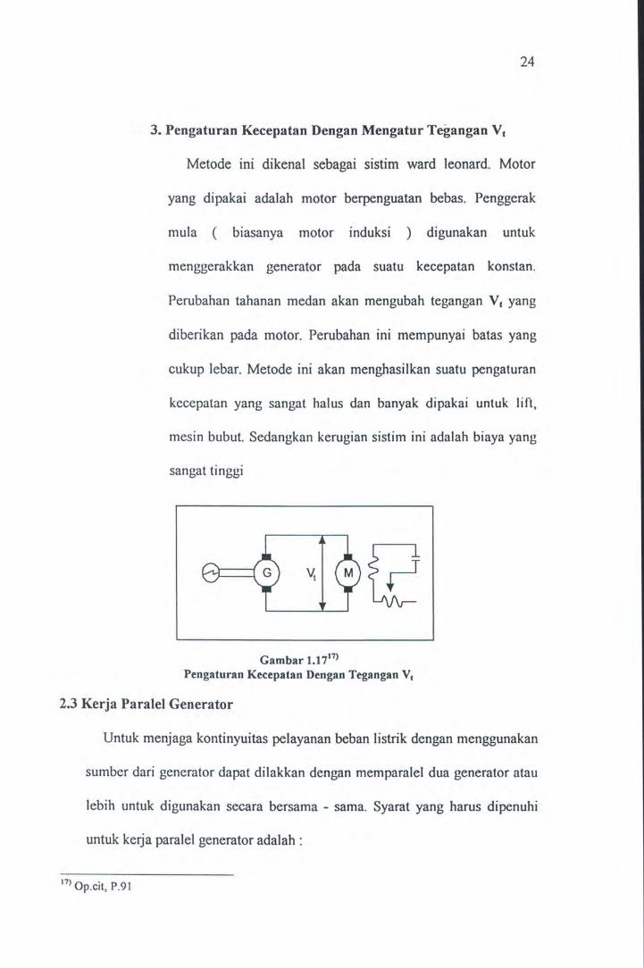
3. Pengaturan Kecepatan Dengan Mengatur Tegangan Vt
Metode ini dikenal sebagai sistim ward leonard. Motor
yang dipakai adalah motor berpenguatan bebas. Penggerak
mula ( biasanya motor induksi ) digunakan untuk
menggerakkan generator pada suatu kecepatan konstan.
Perubahan tahanan medan akan mengubah tegangan v. yang
diberikan pada motor. Perubahan ini mempunyai batas yang
cukup Iebar. Metode ini akan menghasilkan suatu pengaturan
kecepatan yang sangat halus dan banyak dipakai untuk lift,
mesin bubut. Sedangkan kerugian sistim ini adalah biaya yang
sangat tinggi
Gambar 1.1717> Pengaturan Kecepatan Dengan Tegangan V1
2.3 Kerja Paralel Generator
Untuk menjaga kontinyuitas pelayanan beban listrik dengan menggunakan
sumber dari generator dapat dilakkan dengan memparalel dua generator atau
lebih untuk digunakan secara bersama - sama. Syarat yang harus dipenuhi
untuk keija paralel generator adalah :
17>0 . P9 p.ctt, . I

25
1. Tegangan Kedua generator harus sama
2. Frekuensi kedua generator harus sama
3. Fasa kedua generator harus sama
4. Urutan fasa kedua generator harus sama
R----------~--------------S __________ -4---r-------------T----------4-~~----------
Gambar 1.1818> Kerja Paralel Generator dan Jala- Jala
Metode konvensional yang banyak digunakan yaitu dengan menggunakan
lampu sinkronoskop hubungan terang. Benar tidaknya hubungan paralel tadi
dapat dilihat dari lampu tersebut.
Seperti gam bar diatas untuk memparalel generator dengan jala - jala, mula
- mula generator diputar oleh penggerak mula mendekati putaran sinkron,
lalu penguatan Ir diatur hingga tegangan terminal generator sama dengan
tegangan jala- jala. Jika urutan fase sudah sama lampu L., ~' L3 akan hidup
mati dengan frekuensi f1 - fg cycle. Sehingga apabila semua lampu sudah
18> Zuhal, Dasar Tenaga Listrik, ITB, 1986, P.61

26
tidak berkedip berarti r. = fg atau frekuensi tegangan generator dan jala - jala
sudah sama.
Untuk mengetahui bahwa kedua fase sudah sama maka lampu L 1 akan mati
dan ~, L3 nyala terang. Frekuensi tegangan generator diatur oleh penggerak
mula sedang besar tegangan diatur oleh penguatan medan.
2.4 Operational Amplifier
Operational Amplifier merupakan rangkaian terpadu linier yang
mempunyai penguat diferensial berimpedansi input tinggi, penguat tegangan
dcngan gain yang tinggi, penguat output dengan impedansi yang rendah.
Operational Amplifier mempunyai lima terminal dasar : dua untuk suplai
daya, dua untuk isyarat masukan, dan satu untuk keluaran, seperti
ditunjukkan pada gambar berikut ini.
Inverting input
Non-inverting input -------1
v
Gambar 1.1919> Notasi Operational amplifier
19> Herman Wododo, Penguat Operasional dan Rangkaian Terpadu Linier
Erlangga, I 992, P. 13

..
27
Terminal suplai daya Op-Amp
Terminal suplai daya op-amp ditandai dengan +y dan "V untuk
menunjukkan suplai daya yang harus dihubungkan. Besamya suplai daya
bervariasi : ± 6 V, ± 9 V, ± 12 V , ± 15 V, sedangkan suplai tegangan
maksimum bisa mencapai ± 18 V. Op-amp pada pemakaian khusus dapat
digunakan suplai tegangan tidak simetris sperti + 12 V dan -6V. Arus yang
kembali dari op-amp ke suplai harus kembali melalui clemen - elcmen
rabgkaian l uar seperti tahanan be ban.
Terminal output Op-Amp
Terminal keluaran op - amp harus dihubungkandengan tahanan beban RL
dan ujung dari RL yang lain dihubungkan dengan ground. Jadi tegangan
output diukur terhadap ground. Batas arus yang dapat dialirkan dari terminal
output kurang dari 10 rnA. Batas atas tegangan output disebut : + V saturation
( + Yut) , sedangkan batas bawah tegangan output disebut : - V saturation ( ·
Ysat ). Jadi ± V sat : 1 sampai dengan 2 volt dibawah tegangan suplai atau 10%
dibawah tegangan suplai. Misal ± 15 volt menjadi ± V sat = ± 14 volt, ± 13
volt, ± 13,5 volt.
Terminal input Op-Amp
Terminal input diberi tanda + dan - yang disebut dengan terminal input
diferensial karena tegangan output V0 tergantung pada perbedaan tegangan
antara kedua terminal itu, Ed dan gain amplifiemya, AoL· Terminal ouput V0
menjadi positip hila input ( + ) nya lebih positip terhadap input ( - ) nya. Dan

28
V0 menjadi negatip bila input ( + ) nya lebih negatip terhadap input ( -) nya.
Polaritas V0 hanya tergantung pada perbedaan tegangan antara input inverting
dan input non-inverting, perbedaan tegangan ini dapat dicari dengan : Ed =
tegangan input ( + ) - tegangan input ( - ).
E +
Gambar 1.2020)
Polaritas V0 tergantung polaritas tegangan input Diferensial Ed
Jika perbedaan tegangan input Ed cukup kecil, maka tegangan output V0 akan
ditentukan oleh Ed dan gain open loop AoL. Gain open loop adalah gain
tegangan untaian terbuka yaitu membiarkan feetback ouput ke input
dibiarkan terbuka. Sehingga
Vo = Edx AoL ....... .... . .......... . .... ....... . ...... (vii)
2.4.1 Inverting Amplifier
Rangkaian ini merupakan sebuah amplifier yang gain close loop-
nya dari Ei ke V0 ditentukan oleh Rr dan Rh yang dapat memperkuat
inputnya. Untuk memahami cara kerja rangkaian ini perlu dibuat dua
permisalan penyederhanaan realistis yaitu : tegangan Ed = 0 , dan arus
20) Ibid, p 15

29
yang dialirkan oleh terminal input ( +) atau (-) diabaikan. Tegangan
positip Ei dihubungkan dengan tahanan Ri ke input ( - ) op-amp.
Feetback negatif berupa tahanan Rr. Arus I yang mengalir melalui Ri
adalah :
2 1l Ibid, P.33
Ri
Ei
Ei I = R.i . . . .. . .. ... .. . ... . . . . . . . . . . .. .. . . . . . (viii)
Rf
Gambar 1.2121)
Inverting Amplifier
6
RL
Sedangkan impedansi input Zm dari inverting amplifier adalah :
E Zin = T .. .......... ... ... ...... ... ...... .... .. (ix)
Seluruh arus input I mengalir melalui Rr, karena jumlah yang dialirkan
oleh terminal input ( - ) nya dapat diabaikan. Sedangkan arus yang

30
melalui Rr ditentukan oleh R1 dan E1 • Penurunari tegangan yang
melalui Rr adalah:
Ei VRI = I x Rr= Ri Rr ..................... ............. (x)
Pada gambar diatas terlihat , satu ujung Rr dan satu ujung RL telah
dihubungkan. Tegangan dari hubungan ini ke ground adalah V0• Ujung
Rr dan Rr. yang lain berada pada potensial ground. Oleh sebab itu V0
menyamai VRr· Untuk memperoleh polaritas V0 perlu diketahui bahwa
polaritas input E 1 yang masuk ke terminal input ( - ) nya, V0 lebih
negati f dari E1 , maka tegangan output
V0 =-Ei: ............. .. ........ ... .. .. ... .......... (xi)
Dengan memasukkan definisi bahwa gain close loop dari penguat
tersebut sebagai ACL , maka persamaan dapat ditulis sebagai berikut :
AcL = ~~ =- : ............... ... ....... .. ..... ... (xii)
Tanda mmus pada persamaan diatas menunjukkan bahwa polaritas
output V0 terbalik terhadap E1 , maka rangkaian diatas disebut sebagai
inverting amplifier. Untuk input negatif semua persamaan sama dengan
input positif sedang yang membedakan adalah arah arus dan polaritas
tegangan.
Impedansi output dari inverting amplifier merupakan perbandingan
antara gain penguat tertutp dengan gain penguat terbuka yang dikalikan
dengan impedansi output opamp.

31
AcL · ( ... ) Z0 = --x Zoi ....... .. ........... .......... Xlll
Aot.
Arus beban IL yang mengalir melalui RL hanya ditentukan oleh RL dan
V0 saja. Sehingga arus outputnya adalah :
10 = I+ IL ... . . . . . . . . . . . . . . . . . . . . . . . . . . . . . . . .. . . . ... (xiv)
Harga maksimum dari 10 ditentukan oleh op-amp, besamya antara 5 dan
I 0 rnA. Karakteristiknya dapat digambarkan sebagai berikut :
v.
+V..,
""' Eimu
Ei.-. ~ -v ..
Gambar 1.22 Karakteristik Inverting Amplifier
2.4.2 Non Inverting Amplifier
I~
Dengan memberikan sumber tegangan E1 pada input ( + ) op-amp
sehingga polaritas tegangan output V0 sama dengan tegangan inpu E1.
Karena tegangan antara input (+)dan input (-) dari op-amp adalah 0
V , dan berada pada potensial E1 yang sama , seperti terlihat pada
gambar berikut ini.

Ri
+
Ei
Rf
Gambar 1.2322>
Non Inverting Amplifier
32
6
RL
Besamya arus yang mengalir melalui tahanan R1 :
Ei . I=- ...................................... (xv)
R1
Arah arus I tergantung pada polaritas Ei. Karena arus yang masuk ke
terminal negatif ( - ) diabaikan, maka I yang mengalir melalui Rr dan
drop tegangan pada Rf dinyatakan sebagai berikut :
Ri . v Rf = I X Rf = - X Ei ......... .. .... . ........ . ... ... (XVI) R1
Impedansi input dinyatakan dengan :
E Z=
m I
Tegangan outputnya diperoleh dengan menambahkan drop tegangan
pada R1 :
22> Ibid, P47

Rr Vo=E- +- E·
I Rl I
33
= (1 + ~) Ei ... ... ... ... ... ... ... ... ... ... ... (xvii)
Gain close loop non inverting amplifier AcL adalah :
Vo AcL=
Ei
Rr ( """) = 1 + Rl .... .. .... .............. .. ............ XVIlt
Arus beban lu diperoleh dari V ./{. , maka besamya arus output adalah
I o= I+ IL .. . .............. . ...... .............. ... .... (xix)
Impedansi output dari non inverting a,plifier adalah :
AcL Z0 = --x Zoi .............. ... .......... .. ......... . (xx)
Aot
Karakteristik input I output sebagai berikut :
Yo
+V..t
,.., v v E; ....
-V.,.
Gambar 1.24 Karakteristik Non Inverting Amplifier
E;

34
Dari karakteristik diatas dapat dilihat bahwa untuk penguat non
inverting polaritas output sama dengan polaritas input. Pada saat
mencapa1 harga input maksimum, maka tegangan output mencapai
saturasi.
2.4.3 Komparator
Komparator bekerja dengan cara membandingkan sinyal input
dengan tegangan referensi. Sinyal input diterapkan pada salah satu
masukan dari opamp sedangkan tegangan referensi diterapkan pada
masukan lain.
Gambar 1.25 Non inverting komparator
Jika sinyal masukan ( Yin ) lebih besar dari tegangan referensi, maka
tegngan output ( Yout) menjadi positif saturasi ( +ysat ) . Sedangkan jika
sinyal masukan lebih kecil dari tegangan referensi, tegangan output
menjadi negatif saturasi ( -vsat ).
Komparator diatas mempunyai kelemahan yaitu jika sinyal input
sedikit lebih sedikit lebih besar atau lebih kecil dari tegangan referensi
maka akan berakibat tegangan output berosilasi an tara +y sat dan -v sat·
Hal ini sangat riskan untuk sinyal input yang mengandung noise. Untuk

34
Dari karakteristik diatas dapat dilihat bahwa untuk penguat non
inverting polaritas output sama dengan polaritas input. Pada saat
mencapa1 harga input maksimum, maka tegangan output mencapai
saturasi.
2.4.3 Komparator
Komparator bekerja dengan cara membandingkan sinyal input
dengan tegangan referensi . Sinyal input diterapkan pada salah satu
masukan dari opamp sedangkan tegangan referensi diterapkan pada
masukan lain.
Gambar 1.25 Non inverting komparator
Jika sinyal masukan ( Vin ) lebih besar dari tegangan referensi, maka
tegngan output ( V out) menjadi positif saturasi ( +ysat ) . Sedangkan jika
sinyal masukan lebih kecil dari tegangan referensi, tegangan output
menjadi negatif saturasi ( ·vsat ) .
Komparator diatas mempunyai kelemahan yaitu jika sinyal input
sedikit lebih sedikit lebih besar atau lebih kecil dari tegangan referensi
maka akan berakibat tegangan output berosilasi antara +y sat dan ·vsat·
Hal ini sangat riskan untuk sinyal input yang mengandung noise. Untuk

[g)IRJ [g) ~ ~ ~
liEO~~ lO~~ff\IRJ rF~lll

BABIII
TEORI LOGIKA FUZZY
3.1 Pendah uluan
Teori fuzzy pertama kali dikemukakan oleh seorang peneliti dari
California University di Berkeley pada tahun 1965. Teori ini merupakan
generalisasi dari logika multi nilai dan logika konvensional atau logika
boolean dalam kasus - kasus tertentu. Didalam perkembangannya teori ini
banyak digunakan untuk aplikasi praktis seperti kontrol pada otomatisasi alat
elcktronik.
Pada aplikasi kontrol otomatis fungsi utama dari fuzzy adalah dengan
mcndcfinisikan term dan rule sebagai pengganti fungsi matematis yang
komplek dan non linier. Dengan kata lain logika fuzzy merupakan
pendekatan dari penalaran manusia. Yang membedakan antara logika fuzzy
dengan logika konvensional terletak pada proses pengendalian proses
berlangsung. Dengan menggunakan logika fuzzy pengenalan terhadap input
tidak hanya sebatas rendah atau tinggi, dingin atau panas , benar atau salah
tetapi lebih dari itu bisa memberikan derajat keanggotaan dari beberapa
himpunan serta range yang terus menerus. Pada teori probabilitas , suatu
elemen secara pasti hanya mempunyai dua kemungkinan untuk terjadi yaitu"
Ya atau Tidak ". Tetapi dalam teori fuzzy elemen ini dapat mempunyai nilai
keanggotaan ( degree of membership ) yang terletak antara 0 dan 1, seperti
terlihat pada gambar 3.1 berikut ini.
36

37
d d a cui
I
0 linggi 0 ggi 6 5 6 7
boolean fUTL)'
Gam bar 3.113>
Fungsi membership boolean dan fuzzy
3.2 Fungsi Membership
Untuk menyatakan hubungan sebuah input dcngan scbuah hirnpunan fuzzy
diperlukan fungsi membership yang didefinisikan sendiri oleh pemakai.
Didalam sebuah semesta pembicaraan dapat didefinisikan lebih dari satu
fungsi keanggotaan , dengan antara fungsi membership satu dengan yang lain
dapat terjadi saling tumpang tindih (over/aping).
dcrajal membership
~.: label
fungsi m~o·mlx-'nhip
0~-----L--~~~~----~--~ 60~
crisp input
Gambar3.2 >
Istilah dalam fungsi membership
23> -----, FUZZY MICROCONTROLLER DEVELOPMENT SYSTEM, American Neuralogic,
Inc, 1992, P.S. l 24
> ----, Ibid, P.5.8

38
Untuk memberikan membership suatu input ke dalam himpunan fuzzy ada
dua cara yaitu :
( 1 ). Numerik
Membership yang didefinisikan secara numerik dalam himpunan fuzzy
tergantung pada jumlah anggota dalam himpunan atau sebanyak level
diskrit di dalam semesta pembicaraan.
(2). Fungsi
Tingkat keanggotaan yang didefinisikan didalam semesta pembicaraan
dihitung secara fungsional, sehingga semua input yang bearda dalam
semesta pembicaraan akan dapat dicari atau dihitung keanggotaannya
dengan fungsi yang telah ditentukan. Macam - macam fungsi standar
yang sering digunakan adalah :
~Fungsi S
~
l
0.5
0 a
7 /
b c
Gam bar 3.325)
Fungsi S
Fungsi S didefinisikan dengan :
S ( x ; a,b,c ) =0
X
x~a
25l Jun Yan et.all .. , USING FUZZY LOGIC (Prentice Hall Int, 1994), P.18

= 2((x-a) l (c-a))2
= 1-2 ((x-c)l(c-a))2
b~x~c
= 1 x~c
QFungsi n
Fungsi ini didefinisikan dengan :
n (x;b,c) = S(x;c-b,c - b l2, c) x~c
= 1-S (x; c, c + b I 2, c +b) x ~ c
c-b c-b/2
QFungsi T
c+b
Gam bar 3.426)
Fungsi IT
Fungsi ini didefinisikan sebagai :
T (x;a,b,c) = 0
= (x- a) I (b- a)
= ( c- x) I ( c- b)
= 0
26l Jun Yan et.all, Ibid, P 19
X
c+b/2
x~a
a~x~b
b~x~c
x~c
39

0.5
0 a
~ Fungsi Trapcsium
b
Gambar 3.527> Fungsi T
Fungsi ini didefinisikan sebagai :
Tp {x;a,b,c,d)
27> Jun Yan et all, Ibid, P. l9
28> Ibid, P.20
J.1
0.
0 a
=0
= (x- a) I (b- a)
=1
= (d-x)/(d-c)
b c
Gam bar 3.628> Fungsi Trapesium
40
X
c
x ~ a dan x ;?: d
c~x~d
X
d

3.3 Struktur Dasar Pengaturan Logika fuzzy
I Rule Base I Data Base I T ! Penalaran Fuzzy
I Fuzzifikasi I I Defuzzifikasi I
'-.: ~
Input E
Gam bar 3.729'
Struktur Dasar Logika Fuzzy
Output U
""-..>'
41
Dalam pemecahan permaalahan dengan menggunakan logika fuzzy
ada tiga tahapan yang harus dilakukan, yaitu : proses fuzzyfikasi (
fuzzyfication ), proses pengambilan keputusan (rule evaluation), serta proses
defuzzyfikasi ( defuzzyfication).
3.3.1 Fuzzifikasi ( Fuzzification)
Tahap awal yang dilakukan dalam proses logika fuzzy adalah dengan
melakukan pemetaan (mapping) crisp input ke dalam himpunan fuzzy,
proses ini disebut gengan fuzzyfikasi. Data crisp yang sudah dipetakkan
diubah menjadi variabel label dari fungsi membership yang sesuat
dengan nilai fuzzy input. Definisi fuzzyfikasi :
x = fuzzifier (xo)
29> Yan Jun et all, Ibid, P . 47

dimana : Xo = crisp input
x = himpunan fuzzy
fuzzifier : fuzzyfikasi yang memetakkan
3.3.2 Pengambilan Keputusan (Rule Evaluation)
42
Proses ini dimaksudkan untuk mencari nilai aksi ( actioan ) sebagai
tanggapan atas setiap input atau kombinasi input yang diberikan dengan
memberi bobot pada setiap aturan yang diberikan. Didalam proses ini
terdapat dua komponen yaitu : himpunan aturan ( rule set ) dan metode
evaluasi aturan.
Himpunan aturan ( rule set ) adalah semua aturan yang diperlukan
untuk menentukan tanggapan terhadap input atau kombinasi yang
diberikan. Aturan ini bersifat linguistik dan mempunyai bentuk " jika
... maka ... " ( if.. . then ... )
Metode evaluasi aturan adalah metode yang digunakan dalam
mengevaluasi aturan yang sering dipakai seperti mini rule ( mamdani ),
product rule ( larsen ), max - min rule ( zadeh ), arithmatic rule ( zadeh
) dan boolean.
3.3.3 Defuzzifikasi ( Defuzzijication)
Tahapan selanjutnya yang harus dilakukan untuk pengaturan logika
fuzzy adalah mengubah variabel fuzzy yang terbentuk dari pengambilan
keputusan rrienjadi variabel crisp. Defuzzifikasi dapat didefinisikan
sebagai berikikut :

43
Yo = defuzzijier (y)
dimana: y = nilai output fuzzy
Yo= nilai non fuzzy
defuzzifier = proses defuzzifikasi
Metode yang digunakan pada unit difuzzifikasi ini ada dua yaitu :
~ Rata - rata output maksimum (Mean of Maximum I MOM)
Metode ini menghasilkan nilai output rata - rata dari harga output
maksimum fungsi membership.
~ Pusat area (Centre of Area)
Metode ini menghasilkan nilai output yang merupakan gravity
distribusi I pentebaran nilai output fungsi membership.
3.4 Chip Fuzzy NLX 222 P
IC FLC 222 P adalah suatu chip yang berfungsi memproses input dengan
menggunakan metode logika fuzzy untuk menghasilkan output yang
diinginkan. IC NLX 222 P merupakan kontroller yang berdiri sendiri ( stand
alone controller ). Bentuknya PLCC dengan pin sejumlah 44 buah dan
mempunyai spesifikasi sebagai berikut:
1. Memiliki empat buah input analog, empat buah input digital serta empat
buah output analog dan em pat buah output digital.
2. Memiliki enam buah type fungsi membership dan memori sebesar 256
byte.

44
3. Dapat mengelolah sebanyak Ill buah variabel fuzzy dari maksimal 56
buah rule.
4. Mampu memproses lebih dari 500.000 rule per detik.
Diskripsi Pin :
U2
oo&';~)>)>cnc;c;z~ =a~zOO:iJ 00o~
012 ~ §@ PRESCALE AOUT1 m AIN1 AOUTO AIN2 VSS READY vss 000 OUTSEL VREF INSEL 001 NC CH3 013 002 014 003 015 ;gRl~~ 004
l~H~8~~o§~~~~ NLX222P
Gam bar 3.830> FLC NLX 222 P
PIN i FUNGSI ················································!·· .. ······························································································································ Input: i
··illisE:r···························ru~t~k···~~~gi·~~-i~ii~~~i···d~~i~~···ct·~~g~~···si·~-y~C-~icti·r·
I
: low. Harus tetap aktif hingga sedikitnya 8 clock
I untuk memastikan operasi yang lama telah habis.
j Dapat diaktitkan dengan rangkaian delay power up. I 1 Dengan reset akan mengaktifkan mode low power. I
................................................ ! ................................................................................................................................ . DI ( 7 ; 0 ) j Data input digital
I
·-scm····································r··ci·~-~k····i~p~t~···b·~-i~h···di·p~k~r··~k-st~~~i····i·~-p~t····~~~~k··
30> --,STAND-ALONE FUZZY LOGIC CONTROLLERS, (Neuralogic, 1994), P.l

i atau dengan kristal, 1
: dihubungkan ke ground .
dim ana . -
UJung satunya
.............................................. ) ................................................................................................................................ . PROG i Untuk saat pemrograman NLX 222 P saat operasi
1
: harus digrounkan .
................................................ 1.. .............................................................................................................................. . PRESCALE j Input logika "1" menandakan dalam mode prescale
1
: dan "0" dalam operasi normal. Pin ini digroundkan
I saat mode prescale tidak pemah digunakan atau
j dihubungkan dengan READY untuk operast I
1 kontinyu. Mode juga bisa dipanggil selama I
I pengoperasian oleh logika ekstemal setelah RESET
1 diaktifkan PRESCALE input harus dipertahankan I
1 1 pada logika rendah sedikitnya 4 clock. 1
····-·-·-·-········ · ············-············ · ··~········· ····· · ····· ····· ······················ · ··· ······· ·· · ·· ···· ·· ···· ·· ········-········ ·· ··········· ····· ·· ········· ········
AlN ( 3 ; 0 ) j Input data analog, dikonversikan ke 8 bit secara 1
: internal. Input yang tidak dipakai harus digrounkan .
................................................ l ................................................................................................................................ . INSEL i Untuk memilih data input dari input analog atau
1
: digital yang lainnya .
............................................... J ............................................................................................................................... . OUTSEL i Untuk memilih output data dari ouput analog atau
1
: digital yang lainnya .
.............................................. ) ................................................................................................................................ . Output i
··Aau:r··(3··;··a·y········rn~i~--~~tp~t--~~~i~i~···s··b-it··~i"~t~·d-igi.~I"-dik~~~~~~i"k~~-· I
I . I 1 secara mtema .
.............................................. ) ...................•.............................••....•......................................................................... DO ( 7 ; 0 ) i Data output digital
45

AS( 1 ;0) i Pemilihan alamat, pemilihan alaint untuk I
: pengkodean VO digital multiplaxer .
.............................................. ) ................................................................................................................................ . STROBE i Alamat STROBE, menunjukkan validitas data
I
: dalam AS ( 1 ; 0). DO ( 7; 0) dan Dl ( 7; 0 ) .
.............................................. ) ...........................................•..•.................................................................................. READY i Setelah reset pin ini menandakan device mulai
I
: mensample dan memproses data. Pin ini seharusnya
I tidak dihubungkan dengan prescale selama
j pengoperasian. I ................................................ ..,. .................................................................................................................................. .
CH3 j Sebuah bit sebagai indikator bahwa chanel 3 aktive. I
: Untuk aplikasi dimana input tiga rendah atau output
I analog, most significant input dan output digunakan
! bus digital ketika CH3 dihubungkan ke INSEL dan i I OUTSEL I
3.4.1 Arsitektur NLX 222 P
46
Pada gambar 3.9 menunjukkan bahwa bagian utama dari FLC NLX
222 P adalah : fuzzifier , defuzzifier dan controller. Fuzzifier berfungsi
untuk mengkonversi data input ke data fuzzy. Fuzzifier bekeija bersama
dengan kontroler, mengolah data fuzzy sesuai dengan sekelompok rule
yang menunjukkan bagaimana sistim akan dikontrol. Setelah rule di
evaluasi semua, difuzzifier mengubah port output yang dipilih dengan
nilai aksi rule yang menang.

OUTSEL
.. ,,.,, ------' INS£1. ···-- - --------
Gam bar 3.931> Blok Diagram NLX 222 P
47
3.4.2 Membership Function
Membership funtion pada NLX 222 P yang tersedia sebanyak enam tipe
dengan kemiringan ( slope ) konstan. Ke enam membership function
tersbut adalah fungfi left inclusive, symmetrical inclusive , right
inclusive dan lawannya yaitu fungsi exclusive.
Nilai tengah dan Iebar pada membership function umumnya disimpan
dengan nilai tetap di memory, tetapi NLX 222 P menyediakan fasilitas
floating membership function dimana nilai tengah dan Iebar dapat
berubah secara dinamis. Pada tipe floating membership function, nilai
tengah dan Iebar dapat diambil dari salah satu input atau output.
Keuntungan dari tipe floating membership function adalah :
1. Kemampuan untuk mengukur secara langsung perbedaan dua input.
31> Ibid, P.4

48
2. Kemampuan untuk mendapatkan nilai turunan dari nilai input
sekarang dengan nilai input sebelumnya yang telah disimpan pada
output latch terlebih dulu.
3. Menghemat pemakaian memori .
Tipe - tipe membership function dapat dilihat pada gam bar 3.10
dibawah ini.
left Inclusive
~ symmetrical Inclusive right Inclusive
Ltnter
1 Width ~I
l ! left Inclusive
~nter [
1 right Inclusive. J cenier
Gambar 3.1032>
Tipe- tipe Membership Function
3.4.3 Variabel Fuzzy
Untuk mengekspresikan secara linguistik hubungan input dengan
membership function disebut dengan variabel fuzzy. Hubungan ini
32> Ibid, P .5

49
diperoleh dari proses fuzzifier dan menghasilkan input fuzzy yang
mempunyai tingkat membership tertentu untuk menggambarkan tingkat
ke fuzzian input dengan variabel fuzzy tersebut. Sebagai contoh
variabel fuzzy adalah : "Temperatur Dingin ".
Temperatur sebagai input dan Dingin sebagai membership function.
Gambar 3.11 menunjukkan contoh evaluasi variabel fuzzy.
Fuzzy data
cold 631-----..
0
cool mod
60 65 70 75
Input sample
Gam bar 3.1133>
Fuzzifikasi input temperatur
warm hot
80 85
3.4.4 Rule
Sebuah rule terdiri dari beberapa variabel fuzzy dan nilai aksi pada
output. Rule fuzzy digunakan untuk memberitahu kontroler bagaiman
merespon perubahan pada data input. Pada sistim yang memerlukan
umpan batik, pembuatan rule dapat memanfaatkan variabel fuzzy
output yang di feedback ke input. Untuk membuat rule dan
menuliskannya ke kontroler digunakan sofware bantu yaitu Insight.
33> Ibid, P . 6

50
Ada beberapa cara untuk mengevaluasi rule - fuzzy logic,
diantaranya yang digunakan pada NLX 222 P adalah Max of Min.
Langkah pertama (Min) , semua nilai variabel fuzzy pada sebuah rule
dibandingkan dan nilai terendah mewakili rule tersebut. Semakin
rendah nilai rule tersebut berarti tingkat korelasi rule tersebut terhadap
data input semakin rendah. Langkah kedua, (Max) semua nilai rule
yang berhubungan dengan output yang sama dibandingkan dan rule
yang mempunyai nilai tertinggi diambil sebagai pemenang. Nilai aksi
pada output tersebut tergantung nilai aksi rule yang menang. Proses
Max menggambarkan rule yang mempunyai korelasi paling tinggi
terhadap input adalah aturan yang paling dapat dipercaya untuk
merespon data input tersebut.
3.4.5 Floating Membership Function
Floating membership function yang dimiliki oleh NLX 222 P
dengan nilai tengah dan Iebar yang sangat dinamis. Biasanya nilai
tengah dan Iebar mempunyai nilai tetap yang disimpan dalam memory.
Pada nilai floating membership function ini berasal dari beberapa input
atau output. Beberapa membership function dapat dikelompokkan
sebagai floating selama pemasukan perencanaan. Perubahan nilai
tengah dan Iebar dipengaruhi dari pemilihan perubahan input dan
output.
Dalam fuzzifikasi, sebuah input merupakan subtract dari tengah
subuah membership function dan nilai mutlak hasil perubahan

51
pengukuran terdekat yang mendekati nilai tengah. Floating membership
function digunakan oleh variabel fuzzy pada pengukuran langsung
antara dua input yang berbeda.
A .··: : :·· .·
width ~ ... width
center
Gambar 3.1234>
Floating Membership Function
Floating membership function digunakan pada variabel fuzzy
pengukuran langsung perbedaan antara dua input. Metode ini dapat
digunakan untuk kalibrasi sensor yang sudah berubah.
3.4.6 Operational Device
Proses pemasukan data pada NLX 222 P ada beberapa tahapan .
Pertama Pengambilan data yang disimpan pada latch input. Data digital
diambil langsung dari input. Pada NLX 222 P data analog pertama
harus diubah ke digital sebelum diambil. Selanjutnya fuzzy
membandingkan isi input latch dengan variabel fuzzy untuk
mendapatkan nilai untuk variabel fuzzy.
34> Ibid, P.6

52
Fuzzy selalu menampilkan penghitungan Max of Min untuk
mendapatkan rule pemenang. Akhimya defuzzifier dihitung dari nilai
aksi rule pemenang dan diambil untuk dikonversi ke dalam output
analog atau internal feedback.
Fuzzifier
Fuzzifier membandingkan latch dat input dengan mebership
function untuk mendapatkan nilai variabel fuzzy. Pada saat
penghitungan Min ditampilkan dalam semua variabel fuzzy dalam
sebuah rule. Nilai ini selanjutnya disimpan dalam rule. Ketika
penghitungan Max ditampilkan dalam semua referensi rule output
selanjutnya nilai aksi rule pemenang dilewatkan ke defuzzifier.
Pembaharuan Output Latch
Ketika rule atau grup rule berpengaruh terhadap evaluasi output
dan selanjutnya memasukkan rule sebagai referensi output yang lain.
Compailer secara otomatis memasukan code untuk rule terakhir yang
menyebabkan pembaharuan output latch dengan nilai aksi rule
pemenang. Data latch selanjutnya difeedback. Jika setelah proses rule
mempengaruhi output lainnya , controler mendapatkan rule lain atau
grup rule sebagai referensi dari output sebelumnya, maka controler
akan memperbaharui output latch lagi.
Deffuzifier
Nilai aksi rule pemenang dan data mode dimasukkan ke dalam
block defuzzifier. Data digital dari defuzzifier dilatch untuk di drive ke

53
output atau looback internal. Pada NLX 222 P output analog dan digital
tersedia. Jika semua rule dalam sebuah grup sebagai referensi output
adalah nol, sehingga output tidak dapat merubah nilainya. Metode
defuzzifikasi ada dua macam, yaitu : metode acumulate dan immediate.
Fungsi mode immediate adalah sebagai tanda nilai aksi pada rule
pemenang untuk digunakan pada output. Accumulate mode merupakan
akumulasi pengurangan dan penambahan keberadaan output oleh nilai
aksi sebagai rule pemenang. Output merupakan fungsi dari arus aksi
dan output. Accumulate defuzzifikasi dapat digunakan sebagai
pensetabil output ketika sistim dibawah kendali.
3.4.7 Organisasi Memory
NLX 222 P mempunyai memori sebesar 256 byte untuk
menyimpan parameter aplikasi. Tiag puluh dua byte terakhir digunakan
untuk menyimpan nilai tengah dan width yang tetap dari membership
function. Sisanya sebesar 224 byte digunakan untuk menyimpan rule.
Setiap rule memerlukan dua byte ditambah dengan dua byte setiap
penggunaan satu variabel fuzzy. Organisasi memori ditunjukkan pada
tabel berikut ini .

Desimal Address
0
TabeiJ.es> Organisasi Memori
Hexa Address
00
Fungsi
Rules
B B B
54
...................................................................................................................... ...................................................... 223 DF Rules ......................................................... ·········································-··············· ··········································-···-····· ·· 224 EO Center
B B B ........ ................................................. ·············--·-········································ ..................................................... . 239 EF Center ........................................................... ························································· ..................................................... . 240 FO Width B B B ......................................................... ·································-······················· ·-·-·············· ········· ·-························· 255 FF Width
Rule organisasi sebagai grup dari satu atau lebih fuzzi variabel. Setiap
variabel fuzzy dibentuk dari dua byte, seperti ditunjukkan pada tabel
3.1 Byte pertama digunakan untuk menyimpan addres genap dan byte
kedua pada address ganjil.
3.4.8 Timing ( Pewaktu )
Kecepatan pemrosesan adalah fungsi dari rating clock dan jumlah
clock ( 1024 ) yang diperlukan untuk pengambilan data secara lengkap
dan cycle proses. Rating clock maksimum NLX 222 P adalah 10 MHz
dan minimum 1 MHz. Semakin cepat clock maka proses juga akan
semakin cepat dan semakin banyak pula sampling data yang dapat
diproses. Berikut ini gambar timing diagram NLX 222 P.
3~> Ibid, P.8

I i
L
RESET
NN (3;0)
AOUTO
AOUT1
AOUT2
AOUT3
~
LOW
256 clock 256 clock 256 clock 256 clock 256 clock 256 clock 256 clock 256 clock 256 clock .. 1st s
!"AiNN 1...-----.. AIN1
,~ I~
1.. .. ~ .. ~..o_
mple 2nd ,.-- VAiNo' 0:iNT' ~ NN3
~
Gam bar 3.1336>
Timing 1/0 NLX 222 P
mple
AIN2
rd sample I~
'AiN'3 V"AiNo' ~
v---
55
Saat mulai bekerja, pin reset diaktifkan sehingga semua latches
direset menjadi low. Saat pin reset di nonaktifkan, NLX 222 P mulai
mensampling data pertama. Setiap port input membutuhkan 256 clock
cycle untuk sampling data, sehingga untuk keempat port input yang ada
dibutuhkan 1024 clock cycle, port input yang berasal dari internal
feedback tidak memerlukan waktu sampling tambahan karena saat
output dihasilkan maka hasil tersebut akan difeedback dan di latch
diinput. Pada saat pengambilan sampling data berikutnya dilakukan
proses data sebelumnya. Waktu yang diperlukan untuk memproses data
adalah 1024 clock cycle dan tidak tergantung dari banyaknya rule yang
digunakan. Setelah hasil proses diketahui maka output akan
dikeluarkan ke port output yang sesuai.
36> Ibid, P. l 0

56
Pengambilan data input dan memperbaharui data output dilakukan
secara time division multiplexed. Sinyal kontrol yang berfungsi
mengatur pemilihan channel yang akan disampling adalah AS ( 1 ; 0 )
dan STROBE. Sinyal strobe saat tebing naik ( rising edge ) maka data
input sudah siap ( valid ) untuk disampling sesuai pemilihan AS bus.
Dan saat tebing turun ( falling edge ) sinyal strobe maka basil output
telah valid dan siap di-latch oleh rangkaian luar sesuai pemilihan AS
bus. Pemilihan sumber input I output untuk NLX 222 P dilakukan
melalui pin INSEL dan OUTSEL. Pada bagian input, data hanya bisa
dipilih antara analog atau digital. Untuk memilih sumber input data
analog maka pin INSEL diberi input high. Demikian sebaliknya jika
diinginkan input data digital maka INSEL diberi logika low.
AS ( 1; 0) · __ __.X VALID ADDRESSXVALID ADDRESS X ...... __ STROBE
INSEL
Dl ( 7; 0) ------<( VALID DATA >~---------
AI -----------1( VALID DATA)>----
Gambar 3.1437>
Timing Input Diagram NLX 222 P
37> Ibid P 1 I , .

57
Input analog dirubah menjadi data digital dan di-latch di dalam
peri ode 256 clock yang berurutan. Diperlukan 1024 clock untuk
memproses keempat input analog. Pada clock maksimum kecepatan
sampling untuk masing - masing input sebesar 10 KHz a tau 100
mikrodetik.
Data output selalu muncul pada output analog. Pin OUTSEL
memilih sumber data untuk output yaitu analog saja atau digital. Jika
OUTSEL low maka data juga di-latch dan muncul pada bus DO. Pada
gambar berikut ini ditunjukkan timing output NLX 222 P.
AS ( 1; 0} __ .....,X VALIDADDRESSXVALIDADDRESS X ..... __ STROBE
OUTSEL
DO ( 7
; O) ---~< VALID DATA >~---------
AOUT (3;0) ----<( VALID DATA >-<VALID DATA)>-----
Gambar 3.1538> Timing Output Giagram NLX 222 P
Pin CH3 adalah alternatif selain sinyal bus AS untuk aplikasi yang
memerlukan tiga chanel analog I/0 dan satu chanel digital I/0.
38) Ibid ' p .11

58
Pada mode yang tetap ini diperoleh keuntungan yaitu tidak diperlukan
perangkat keras luar karena tidak diperlukan pengkodean alamat. Pin
CH3 dapat dihubungkan ke OUTSEL untuk mengontrol sumber output
atau INSEL untuk memilih sumber input analog atau digital.
Mode prescale digunakan untuk mengatur kecepatan sampling data
secara internal hardware. Lokasi terakhir pada memori, yang biasanya
digunakan untuk menyimpan nilai counter untuk keperluan operasi
prescale. Saat counter masih berjalan, NLX 222 P non aktif selama
1024 clock cycle setiap satu hitungan.
CH3
STROBE
DO (7;0)
AS (1;0)
AOUT (0, 1 ,2)
AOUT3
39) Ibid ' p .11
< VALIDDATA > <
<
AS=3 >-< VALID DATA
< VAUDDATA
VALIDDATA >
Gam bar 3.1639>
Timing Output Chane! CH3
> >

~LPJ~~VJ
r[~[~C~~~~~ LPJl~l

BABIV
PERENCANAAN ALA T
4.1 Perencaan Perangkat Keras
Didalam pembuatan alat auto sinkron generator perlu diperhatikan jenis
generator yang digunakan sehingga pengaturan yang dikehendaki dapat
dicapai. Pada tugas akhir ini digunakan generator sinkron ( alternator )
dengan pengerak mula ( prime over ) berupa motor de. Penguatan yang
diberikan pada rotor untuk mendapatkan eksitasi merupakan jenis pengut
terpisah yaitu dengan memberikan sumber de sebesar 0 - 25 VDC, 25 A.
Sedangkan motor de yang digunakan merupakan jenis motor de shunt dengan
tegangan nominal 220 VDC.
Data spesifikasi generator-set :
Alternator syncrone :
Motor DC:
Mark : Hampden
Armatur Voltage : 220 I 380 V
Armatur ampere : 8,3 I 4,8 A
Frequency : 50 Hz
Phase : 3 Phase
Hp: 2 Hp
RPM : 1500 RPM
Mark: Hampden
59

Armature Voltage : 220 VDC
Armature Ampere : 9 A
Shunt Field Voltage : 220 VDC
Shunt Field Ampere : 0,25 A
Hp: 2 Hp
Kw : 1,5 Kw
RPM : 1500 RPM
4.1.1 Sistem Autosinkron Generator- PLN
60
Kerja paralel antara generator dengan sumber PLN dimaksudkan
untuk mendapatkan daya yang lebih. Syarat yang harus dipenuhi dalam
kerja peralel adalah :
1. Urutan phase harus sama ( Ro = Rp; S0 = Sp; T0 = T p ).
2. Tegangan PLN harus sama dengan tegangan generator.
3. Frekuensi PLN harus sama dengan frekuensi generator.
Jika ketiga parameter tersebut sudah dipenuhi maka genertaor tersebut
dapat diparalel dengan jala- jala PLN.
Urutan phase harus disamakan atau dipastikan sama terlebih dulu
sebelum generator diparalel. Hal ini dapat dilakukan dengan pengujian
pada alat pendeteksi phase, dengan demikian urutan phase keduanya
sama. Untuk menaikan dan menurunkan tegangan generator maka
eksitasinya diatur,yaitu dengan jalan menambah tegangan pada medan
rotor untuk menaikkan tegangan. Sedangkan untuk menurunkan
tegangan generator yaitu mengurangi sumber tegangan pada medannya.

61
Frekuensi generator diatur dari penggerak mula (prime over) yaitu
motor de. Dengan menaikan keeepatan motor de maka frekuensi yang
akan dihasilkan oleh generator akan semakin tinggi, demikian
sebaliknya. Pada gambar 4.1 ditunjukkan blok diagram sistim auto
sinkron generator- PLN.
I PLN I I
SENSOR TEGANGAN 1---
--SENSOR FREKUENSI
FLC NLX 222P
I LOAD I ,---+
SENSOR BEDA PHASE ~
I RELAY I i l I GENSET ]
Gambar 4.1 Blok Diagram Sistim Autosinkron
Cara kerja rangkaian sebagai berikut :
1. Sebagai sumber listrik utama adalah PLN, sedangkan GENSET
merupakan sumber eadangan yang dipersiapkan untuk penambahan
day a.
2. Sistim Tegangan dari PLN 3 phase 200 volt, frekuensi 50 Hz
dihubungkan ke beban.
3. Generator 3 phase dihidupkan, kemudian dilihat urutan phase yaitu :
phae R, phase S, dan phase T.

62
4. Setelah urutan phase sudah sesuai R,S, T maka tegangan output diset
sebesar ± 200 volt dengan frekuensi ± 50 Hz.
5. Sensor tegangan akan mendeteksi besar tegangan antara PLN dan
GENSET. Tegangan PLN sebagai referensi diset pada posisi 200
volt akan dibandingkan dengan tegangan GENSET.
6. Jika tegangan dari GENSET kurang dari 200 volt maka FLC NLX
222P akan mengontrol dan memberikan sinyal tegangan pada
rangkaian eksitasi untuk menambahkan tegangan sehingga dicapai
tegangan pada output GENSET sebesar 200 volt. Dan jika tegangan
dari GENSET lebih dari 200 volt maka controller akan memberikan
sinyal pada rangkaian eksitasi untuk mengurangi atau menurunkan
tegangan pada eksitasi hingga output GENSET mencapai 200 volt.
7. Frekuensi GENSET sebesar ± 50 Hz dibandingkan dengan frekuensi
dari PLN melalui sensor frekuensi ke tegangan.
8. Jika frekuensi GENSET kurang dari 50 Hz maka FLC NLX 222P
akan mengontrol dan memberikan output pada rangkaian pengaturan
kecepatan motor de untuk menambahkan kecepatannya sehingga
dicapai frekuensi sebesar 50 Hz. Apabila frekuensi GENSET lebih
dari 50 Hz maka controller akan memberikan sinyal tegangan pada
rangkaian sensor pengaturan kecepatan motor de untuk mengurangi
kecepatannya sehingga dicapai frekuensi sebesar 50 Hz.
9. Setelah semua parameter atau syarat untuk kerja paralel generator
sudah terpenuhi maka controller akan memberikan sinyal tegangan

63
ke relay untuk menghubungkan ( menggerakkan ) magnetik
kontaktor pada posisi hubung (closing) dengan PLN.
4.1.2 Rangkaian Sensor Tegangan
IN
Gambar 4.2 Sensor Tegangan
+12V
OUT
Untuk mendeteksi tegangan output generator maupun tegangan jala
- jala dari PLN, maka diperlukan rangkaian sensor tegangan seperti
pada gambar 4.2 diatas. Rangkaian sensor tegangan ini mendapatkan
input 220 V AC langsung dihubungkan dengan pembagi tegangan RDI
dan Rm yang kemudian dimasukkan pada pengikut tegangan voltage
j ollwer dengan opamp LM 301A Output dari LM 301A dimasukkan
kedalam rangkaian penguat diferensial. Rangkaian diferensial seperti
pada gambar 4.3 berikut ini. Pada rangkaian diferensial output dari
generator dimasukkan pada terminal ( - ) opamp LM30 1 sedangk(l.n
output dari PLN dimasukkan pada terminal ( + ) sehingga selisih
tegangan antara V + dan V_ merupakan inputan bagi NLX 222P.

FROMGENSET
FROM PLN
R6 100K R8 100K
+12V
2 R6 100K 6
3
IC2 "'O> ~ LM301A
-12V
Gambar4.3 Rangkaian Diferensial Amplifier
4.1.3 Rangkaian Sensor Frekuensi
64
TO FUZZY
Untuk mengetahui besamya frekuensi baik dari jala - jala PLN
maupun generator, maka diperlukan rangkaian pendeteksi frekuensi.
Pada perancangan ini digunakan opamp IC LM 2907, yaitu IC yang
mempunyai fungsi sebagai perubah dari input frekuensi menjadi ouput
tegangan (Frequency to voltage converter) . IC ini mempunyai gain
yang sangat tinggi dan sangat mudah dalam penggunaannya. Pada
gambar 4.4 berikut ini ditunjukkan rangkaian sensor frekuensi.
Besamya frekuensi yang terukur oleh IC LM 2907 dirubah menjadi
tegangan de. Proses konversi ini dipengaruhi oleh komponen -
komponen antara lain : pewaktuan kapasitor, output resistor, dan
sebuah integrator. Besamya tegangan output yang dihasilkan dinyatakan
dengan rumus sebagai berikut ;

Dimana : V0 : Tegangan output ( volt )
fiN : Frekuensi input ( Hz )
V cc : Tegangan kolektor
C1 : Capasitor (F)
R1
220VAe 220k
Gambar4.4 Rangkaian Sensor Frekuensi
65
vee
TO DIFFERENSIAL
Selisih tegangan antara output dari PLN dengan generator dari
penguat diferensial merupakan analog input bagi NLX 222P.
4.1.4 Rangkaian Sensor Phase
Phase atau beda phase merupakan salah satu parameter yang harus
dikontrol selain kedua parameter diatas. Phase dari generator
dibandingkan dengan phase dari jala - jala PLN, sehingga tegangan
antara generator dengan PLN menjadi se-phase. Untuk itu maka perlu
adanya rangkaian sensor phase untuk mengetahui perbedaan atau selisih
·.

66
phase antara generator dengan PLN. Output dari penguat diferensial ini
dimasukkan ke analog input NLX 222P.
PLN
GENSEl
4.1.5 Kontroler
R4
Gambar 4.5 Rangkaian Sensor Phase
NLX 222P memiliki empat buah input analog, empat buah input
digital serta empat buah output analog dan empat buah output digital.
Pada perancangan tugas akhir ini hanya menggunakan input analog
saja sedangkan input digital tidak digunakan.
Pemilihan kana! input yang aktif dilakukan oleh dekoder alamat (
Channel input ) . Address selector ( AS 1 :0 ) yang dibangkitkan oleh
NLX 222 P digunakan untuk memilih kana! input atau output yang
aktif. Pulsa STROBE dari NLX 222 P digunakan untuk mengaktifkan
dekoder alamat saat data valid pada data bus input untuk dibaca pada
kana! input atau data valid pada data bus output untuk dikirimkan pada
kana! output

67
Pada input analog diberikan suatu rangkaian proteksi dan buffer
sebelum masuk ke input analog AIN ( 3;0 ). Rangkaian ini diberikan
untuk masing - masing input analog dan digunakan untuk membatasi
tegangan sinyal input sehingga tidak melebihi kemampuan maksimum
input ADC internal NLX 222 P sebesar V cc - 0,5 volt. Sedangkan
rangkaian buffer digunakan agar tidak membebani ADC internal NLX
222 P karena impedansi input analog sebesar 150 Kn. Berikut ini
gambar rangkaian proteksi dan buffer.
ANALOG INPUT
Gambar4.5 Rangkaian proteksi dan buffer
Karena pada bagian input hanya diperlukan data analog saja, maka pin
INSEL perlu diberi logika high yaitu dengan dihubungkan ke V cc·
Sedangkan pada bagian output selain output analog juga diperlukan
output digital, maka pin OUTSEL perlu diberi logika low yaitu dengan
dihubungkan ke ground. Berikut ini gambar rangkaian kontroller fuzzy
NLX222 P

68
4.1.6 Rangkaian Driver
Output dari controller NLX 222P digunakan untuk mengatur
tegangan output, frekuensi, dan phase generator, penghubung switch
(closing switch) serta tampilan berupa display LCD.
Pengaturan tegangan generator
Tegangan yang dihasilkan dari generator tergantung pada berapa
besar eksitasi yang diberikan pada kumparan medan. Eksitasi yang
diberikan berupa tegangan de sebesar 0- 25 Volt 25 Amper. Pengaturan
tegangan ini dilakukan oleh NLX 222P melalui rangkaian transistor
seperti pada gambar berikut ini.
R3 +
50K
Gambar4.7 Rangkaian Driver Eksitasi
Pengaturan frekuensi generator
Frekuensi yang dihasilkan oleh generator tergantung pada
penggerak mula ( motor de ). Dengan mengatur kecepatan putar motor
de maka frekuensi yang dihasilkan dapat berubah - ubah. Untuk

69
mengatur kecepatan motor de dilakukan dengan merigatur tegangan
input. Semakin besar tegangan yang diberikan maka semakin tinggi
pula kecepatan putamya. Tegangan nominal motor de yang digunakan
sebesar 220 Volt. Rangkaian driver kecepatan berupa transistor yang
dihubungkan seri dengan kumparan shunt. Rangkaian driver seperti
pada gambar 4.8 berikut ini.
OUT FUZZY
Driver switch
Gambar4.8 Rangkaian Driver Kecepatan
TO MOTOR DC
SD841
Setelah semua parameter diatas terpenuhi maka output dari NLX
222P akan men-driver relay untuk menghubungkan tegangan output
generator 3 phase dengan tegangan jala - jala PLN. Rangkaian ini
menggunakan transistor 2N3055 dua buah dirangkai secara darlington
yang berfungsi sebagai switch. Untuk melindungi transistor dari arus
balik kumparan maka dipasang dioda sebagai pengaman.
4.2 Perencanaan Perangkat Lunak
Dalam perancangan software fuzzy logic controller NLX 222 P berupa aturan
- aturan (rules) fuzzy yang berfungsi untuk mengontrol proses sinkronisasi

70
generator dengan PLN. Dalam pembuatan aturan fuzzy ini dilakukan langkah
- langkah sebagai berikut :
4.2.1 Menentukan input I output yang diperlukan
Input yang dimiliki oleh fuzzy logic controller NLX 222 P
sebanyak em pat buah kana! input yang dapat dipilih analog atau digital.
Input yang digunakan dalam perencanaan ini adalah :
rrf AINO : Input Voltage ( Tegangan)
rrf AIN 1 : Input Freq ( Frekuensi )
rrf AIN 2 : Input Phase ( Beda Phase )
Input internal sebanyak 3 input diambilkan dari feedback dari output :
rrf Speed
rrf Relay
rrf Frek OK
Output analog yang digunakan adalah :
rrl AOUTO : Exitacy
rrl AOUTI : Speed
rrl AOUT2 :Relay
rrl AOUT3 : FreqOK

71
Gambar 4.9 berikut ini menunjukkan hubungan input- output NLX
222P.
Speed Relay
FreqOK Voltage
Freq Phase
--+ .. ..
.. NLX 222P
Gambar4.9 Hubungan Input Output NLX 222P
4.2.2 Pembuatan Fuzzy Set
.. .. Speed
Relay
.. FreqOK
.. Exitacy
Untuk menentukan variable fuzzy dalam penulisan software insight
maka perlu dilakukan inisialisasi sebagai berikut :
< natecendent > is < fuzzy set > (center, widht, membership functions
) antecendent yang digunakan adalah:
Input Output
Voltage (Sensor Tegangan) Exitacy ( Pengaturan Tegangan Genset)
Freq ( Sensor Frekuensi ) Speed ( Pengaturan Frekuensi Genset )
Phase ( Sensor Phase ) Relay ( Driver closing )
" Antecendent Voltage, Variabel fuzzy:
1. Voltage is VoiHigh ( 128 , 15, Left Exclusive)

72
2. Voltage is VolLow ( 128, 15 , Right Exclusive) -
3. Voltage is VolOkay ( 128, 15 , Symetric Inclusive)
Low Okay High 63
0 128 255
Gambar4.10 Variabel Fuzzy Untuk Antecendent Voltage
" Antecendent Freq , Variabel Fuzzy :
1. Freq is FreqLow ( 128, 10, Right Exclusive)
2. Freq is FreqHigh ( 128 , 10 , Left Exclusive )
3. Freq is Tepat ( 128, 10, Symetric Inclusive)
Low Center High 63
0 128 255
Gambar4.11 Variabel Fuzzy Untuk Antecendent Freq
" Antecendent Phase, Variabel Fuzzy :
1. Phase is PhaseLow ( 128, 10, Symetric Exclusive)

73
NoSynch Synch 63
0 255
Gambar 4.12 Variabel Fuzzy Untuk Antecendent Phase
" Antecendent Relay, Variabel Fuzzy:
1. Relay is NoSynch ( 128 , 0 , Right Exclusive )
2. Relay is Synch ( 128 , 0 , Left Exclusive )
NoSynch 63
Synch
0 255
Gambar4.13 Variabel Fuzzy Untuk Antecendent Relay
" Antecendent FreqOK, Varia bel Fuzzy:
1. FreqOK is Okay ( Speed , 0 , Symetric Inclusive )
2. FreqOK is NoOkay ( Speed , 0 , Symetric Exclusive)

74
63
0 Speed 255
Gambar4. 14 Variabel Fuzzy Untuk Antecendent FreqOK
4.2.3 Pembuatan Aturan Fuzzy (rule set)
Tahapan terakhir dalam pembuatan software adalah membuat
kumpulan aturan (rule set). Proses pembuatan rule dengan software
Insight sebagai berikut :
Rules
If Relay is NoSynch and Freq is FreqLow then Speed + 1 If Freq is FreqHigh is Relay is NoSynch then Speed+ - 1 If Phase is PhseLow and Relay is NoSynch and FreqOK is Okay then Speed + 1 If Relay is NoSynch and Freq is Tepat then FreqOK =Speed If Voltage is VoiHigh and FreqOK is NoOkay and Freq is Tepat then Exitacy + - 1 If Voltage is VoiLow and Relay is NoSynch and Freq is Tepat then Exitacy + 1 If Voltage is VolOkay and Relay is NoSynch then Relay= 255

75
START
SPEED +1/-1
SPEED +1
RELAY
Gambar 4.15 Diagram Alir Kumpulan Aturan Fuzzy


BABV
PENGUnANDANPENGUKURAN
5.1 Pengukuran Tegangan Generator
Tegangan line ( VL ) dari PLN di set pada tegangan 50 volt, sehingga
tegangan dari output generator harus sama dengan tegangan PLN atau
toleransi sebesar 5 % ( ± 2 volt ). Hal ini dikarenakan keterbatasan komponen
yang ada di pasaran. Untuk mengetahui kinerja dari alat ini khususnya untuk
driver tegangan ( excitacy ), maka dilakukan pengukuran tegangan output
generator terhadap waktu pada sisi tegangan PLN sebesar 50 volt. Dari hasil
pengukuran didapat tabel sebagai berikut :
TabelS.l Hasil Pengukuran Tegangan Generator
NO Vp_p PLN Vp_p Generator T ( detik)
I. 50 0 0 2. 50 6 5 3. 50 11 10 4. 50 17 15 5. 50 24 20 6. 50 32 25 7. 50 43 30 8. 50 52 35 9. 50 51 40
10. 50 52 45 11. 50 52 50 12. 50 49 55 13. 50 48 60 14. 50 49 65 15. 50 50 70 16. 50 49 75 17. 50 49 80
76

77
18. 50 52 85 19. 50 51 90 20. 50 52 95 21. 50 52 100 22. 50 53 105 23. 50 50 110 24. 50 51 115 25 . 50 50 120
Dari tabel diatas dapat di gambarkan grafik tegangan generator terhadap
waktu seperti gambar dibawah ini . Tegangan generator mencapai 50 volt
pada waktu ± 30 detik, setelah itu terjadi fluktuasi berkisar antara 48 volt
sampai dengan 53 volt. Jadi selisih tegangan antara tegangan generator
dengan tegangan PLN sebesar ± 3 volt atau sebesar 6 % pada saat sinkron (
tegangan generator dianggap sama dengan tegangan PLN ).
I Tegangan Generator Terhadap Waktu
I 60 T -··-· ·• ··- -- ·· -··----··--·-·-·---·-·-·
c co Cl
:! ; 30 Cl
~ 20
10
(") It)
Waktu
Gambar 5.1
--·- ---·--·1
en ...... (") N
I
It) N
Tegangan Generator Terhadap Waktu
5.2 Pengukuran Frekuensi Generator
Frekuensi dari PLN sebesar 50 Hz merupakan frekuensi referensi bagi
generator untuk mencapai nilai sinkron yang diinginkan. Pada saat pertama

78
menurunkan kecepatan putar motor de untuk mendapatkan frekuensi sebesar
50 Hz. Dari pengukuran yang dilakukan terhadap waktu besamya frekuensi
antara 50 - 57 Hz. Sedangkan frekuensi dikatakan sinkron ( dianggap sama
dengan frekuensi PLN ) sebesar 50 - 51 Hz. Berikut ini hasil pengukuran yang
dicapai sebagai berikut :
Tabel5.2 Hasil Pengukuran Frekuensi Generator
NO fPLN (Hz) feenerator ( Hz ) T ( detik)
1. 50 0 0 2. 50 63 5 3. 50 53 10 4. 50 52 15 5. 50 51 20 6. 50 51 25 7. 50 51 30 8. 50 50 35 9. 50 51 40
10. 50 50 45 11. 50 50 50 12. 50 50 55 13. 50 50 60 14. 50 50 65 15. 50 50 70 16. 50 50 75 17. 50 50 80 18. 50 53 85 19. 50 50 90 20. 50 57 95 21. 50 50 100 22. 50 51 105 23 . 50 51 110 24. 50 50 115 25 . 50 50 120

79
Frekuensi Terhadap Waktu
70 . - -·----·--·· - .. --- --·-·'--- ---~-----·-~-------·-
!
60
50
'iii 40 t::
ell :::1
.l&: 30 ell ... LL.
20
10
0 . M L() ~ m ~ M LO ~ m ~ M LO
I i
..- ..- ..- ..- ...- N N N
Waktu
I _____
Gambar 5.2 Frekuensi Generator Terhadap Waktu
Dari grafik diatas terlihat bahwa pada saat fuzzy mendapat input, maka
kecepatan motor ditambah sampai mendekati frekuensi sinkron, yaitu pada
saat waktu baru 5 detik frekuensi langsung menunjukkan 63 Hz kemudian
secara berangsur - angsur turun mendekati frekuensi sinkron_ Dan pada saat
detik ke 40 frekuensi menunjuk 50 Hz ini berarti kondisi sinkron untuk
frekuensi sudah tercapai .
5.3 Pengujian Generator dengan Behan
Pada saat kerja paralel Generator - PLN diberi beban berupa motor induksi
3 phase 0,25 Kw sebagai beban induktif dan lampu pijar 220V I 125W
sebagai beban resistif, maka hasil pengujian sebagai berikut:
Tabel5.3 Basil Pengukuran Generator beban lnduktif
T ( detik) Vp.p (Volt) Frekuensi ( Hz ) Arus (A ) Cos <p
180 49 51 0,15 0.98

80
Tabel5.4 Hasil Pengukuran Generator Beban Resistif
T ( detik) Vp_p (Volt) Frekuensi ( Hz ) Arus (A) Cos <p
180 49 51 0,082 1
Dari pengukuran diatas waktu yang diperlukan untuk tercapainya proses
sinkronisasi tersebut cukup lama, hal ini disebabkan oleh driver eksitasi atau
rangkain pengendali arus eksitasi yang tidak stabil.

PJ @J PJ \\ff ~
riErNJ~T~r
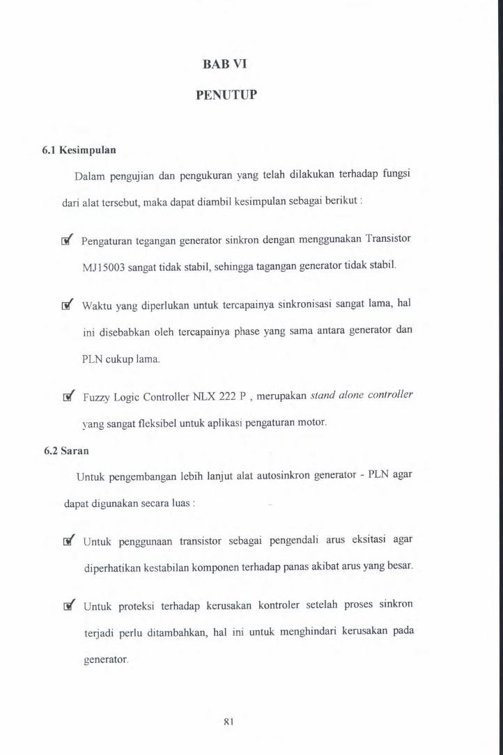
6.1 Kesimpulan
BABVI
PENUTUP
Dalam pengujian dan pengukuran yang telah dilakukan terhadap fungsi
dari alat tersebut, maka dapat diambil kesimpulan sebagai berikut :
rfl Pengaturan tegangan generator sinkron dengan menggunakan Transistor
MJ15003 sangat tidak stabil, sehingga tagangan generator tidak stabil.
rfl Waktu yang diperlukan untuk tercapainya sinkronisasi sangat lama, hal
ini disebabkan oleh tercapainya phase yang sama antara generator dan
PLN cukup lama.
rfl Fuzzy Logic Controller NLX 222 P , merupakan stand alone controller
yang sangat fleksibel untuk aplikasi pengaturan motor.
6.2 Saran
Untuk pengembangan lebih lanjut alat autosinkron generator - PLN agar
dapat digunakan secara luas :
rfl Untuk penggunaan transistor sebagai pengendali arus eksitasi agar
diperhatikan kestabilan komponen terhadap panas akibat arus yang besar.
rfl Untuk proteksi terhadap kerusakan kontroler setelah proses sinkron
terjadi perlu ditambahkan, hal ini untuk menghindari kerusakan pada
generator.
Rl


DAFTAR PUSTAKA
Coughlin, RobertF, Frederick, F. Driscoll, OPERATIONAL AMPLIFIER LINIER
INTEGRA TED CIRCUITS, Prentice Hall Inc, Englewood Cliffs, New york,
1982.
Jun Yan, Michael Ryan, James Power. USING FUZZY LOGIC. Prentice Hall,
1994.
Neuralogic. FUZZY MICROCONTROLLER DEVELOPMENT SYSTEM,
American Neuralogic, Inc, 1994.
Zuhal, DASAR TENAGA LISTRIK, ITB, 1986
Gupta J.B, ELECTRICAL MACHINES - I, Katson Publishing House, 1980
82


.a .. •
A 8 c 0 E
( (
!F"
( ROUT2
? 11<5
+12V r-
r- To Fuzzy IN [
~ ROUT1
""'"' 11<5
RD1 R1 _2. r::--... R6 100K RS 100K
220K/1W 100k 6
""' """ ~ ~ 3
FROM PLN +"""" +12V ' 3 ~ RD2 R3 (
I;-IC1
3
< 1K/1W 50K? """'~ LM301A
~ > I[ "'"' ~ ~ 21'...._
· 12V -~ .. A../'v 3 • """" ~ R7 100K ....- IC2
"""'~ LM301A
) RS
~ 100K -12V
~
2 2
+12V
[
""'"' RD3
R4 _2. -........_
FROM GENSET <::> 22~1W 100k 3-~
~ ~ .,..,. ~~
> RD4 R6 > ,.,- IC2 ) 1K/1W ~ """' ~ LM301A ~ 50K ~ [
...!:=:- ~ -12V
, , ~le
RANGKAIAN INPUT TEGANGAN
s~ I Document Number rv Date: Sheet 1 of 1
A B c 0 E

~
A B c
vee
220 VAe [ PLN I R1 c---~~"'-----1r-------------W1 F GNo t---41~--t---,
~----------~2:...1 C REF
~ 3
<•K r~,T~ . .; ~ -::::- -===- -=-
s~4 _l_Ok
vee
220 VAC [ GENSET I R5 c---~~~--,-------------------1~---~ F GNO t--'--._--1--
A
r----------~2:...J e REF
~M 3
.K r~, r: : : t---... +--~ ~
-===-- -===- ~
B
5~8 _l_Ok
c
0
R12 ..A.,/'v
-1~00K
il
... lUI
~ 100K~
R10 .A/'-
100K
R17} 100K
...,,_
+12
U? LF35E
6
+51/ .... iR14 ?11<5
( R13 (11<5
itle SENSOR FREKUNSI
~ize l Document Number A FREKUNSIKETEGANGAN
E
Date: uesdav. A~ust 26. 1997 Sheet 1 of 0 E
TOFUZZV
I+
rev
_ IPUL

PLN
GENSET
21
"
10K
10K
"
01 1N4148
03
LM336-2.5V
R12 <. 2K2
B
02 1N4148
~~' 10K
R4
10K
U1A n084
Tc' C1 10uF o.1uFI
U4B
5 7 ' n084 ·-·
m~ C3 I10uF 0.1uF
VEE
B
c 0
VR1
100K
' C>VREF
-
itle
c
R9 10K
VREF R11 10K
R10
10K c
5.6nF
E
SENSOR BEDA PHASE
heet 1 of E

ANALOG INPUT 0
ANALOG INPUT l
ANALOG INPUT 2
ANAWG INPUT 3
J1
n
.. ~VOD ,.,
.. ~VOD ,.,
"""
ANALOG OUTPUT
...
l¥f J7
l¥f
,,.
, ..
"""
.,. ll<>
"""
.,. "'
T~ r~ T
POWER SUPPLY ...
~L. JIW
020 , ..
DIGITAL INPUT (DI7:0)
"""
JPB
Cll D.1uf
....... ~ - ~ nr, 0 ' X!tQ 0 l llf:Q 0 I IRH
.. . .... ~--~ I)H$
"""
DIGITAL OUTPUT (D07:0)
.IP10
Wt<EADE.2 ~':' •••• ,
<>-t 0 o--0 o-;
o--IN:SF! 0 - ' QtU$1'1 ! 0 Rf$0 I 0
PftFSCAJ f i 0
MODUL FLC NLX222P

A B c D E
• •
f-
R3 +3(N
3 .Av
3 50K
+30V p
.... CJI
21' OUT FUZZV R1 ~-':--....... 6 L Q1
... v"v 3 74~ r SC1014 L f4-~ ...... Q2
~ 0 10K r MJ11032
~5. 1V ....,_
< R2 ,C ? 10K5V > ~
TO GENERATOR
2 ~
2
~
, , rtle
DRIVER EKSIT ASI ~iz~ I Document Number
IPUL rv ..>ate: uesday, Sep1ember 02 1997 5heel 1 of 1
A B c D E

A B c D E
~ ~
1-
'
3 3
TO MOTOR DC [ ~
~ ... "' .. ..__l_i":: ...... R?
OUTFUZZV 6 1.1 3 74~
...,... r S0841
~ RESISTOR ...,_ !!1c
2 2
f-
, , rtle
DRIVER SPEED ~iz: I Document Number
IPUL rev
pate: uesday, September 02 1997 13heel 1 of 1 A B c D E

c.~
r.~--- . . r )
Features
· NLX221, NLX221 P NLX222·· ;NLX222P ' . Stand.-Aione Fuzzy Logic Controllers Preliminary Data . ·
Description • Complete, Single-Chip Fuay Controller Fuuy logic is :a powerful procc.ssing methodology th:tt ;~ccom
mod:.tcs imprecise input d:.t:a ant11ystcm nonlinc:uitics c:uily for r:tpitl development of robust control systems.
• Flo:~ibl.:, Sclf-Ad~pting Control
• EEPROM or OTP Stor~gc
• An~ log md Digit~! Inputs
An~ lor, :md Digit~! Outputs
• Six Typ.:s of l\1cmbcrshif1 Funr:tions
• II I Fuzzy VuiJblc.s
Up to 50 Rules
• PC-B:ued Development System
• PLCC P:.cbge (NLX222P 44-Pin. NLX221 P 28-Pin)
Applications
• Power md B~llery Management
• Motor Control
• ll.::atcr Control
• Automotive
• lndustri:~l Control
11tc methodology uses linguistic descriptions of systems, m:ak· ing it intuitive :and simple to use. Fuzzy logic can be used to in.:xpcnsivcly ~dtl intelligence to a wide variety of products.
· Fuzzy logic c:.n improve performance, :add fc:.tures. and in.:rc:.se efficiency.
The NLX221 and NLX222 :ue inexpensive, high·pcrformwce, st:tnd-:alone fuzzy logic controllers. The devices perform fuzzy logic c:alcul:llions di~ectly in h:udw:ue. Because they :uc dedicated controllers, the NLX221 :tnd NLX222 offer superior ease-o'C-use, pcrform:ancc, featurc.s, and robustness in hmh opcuting cnvironmcnu.
1
Both devices have sep:ar:tte eight-bit tnput and output busses. The input bus is multiplexed to· s:ample dal:a over four time slots and m:ay s:ample up to eight sep~~r:ate sources of d:at:a at a
. time. The NLX222 :!lso h:as four an:alog inpuu und four walog outpulS. In any sampling time period, either analog or digital dat:1 can be useu as input.
Figure 1. NLX221P and NLX222P Package Pin Aulgnment~
NLX221(P)
Copy"gnt 0 1993. 1994 Neuralogix
•.
PRESC.t.l( READY
. 000
. DOl
DOZ DO~
004
'
DIZ AIXITI
~OUTO
v .. v ..
OUTSEI. r<SEI.
N'C DO OM DIS
NLX222(P)
a & ~ ~ ~ ~ t~l!i ~ :It PRE SeAlE
31 AIHI
n ~INZ
31 READY
:IS 000 )4 VREF ;)3 DOt S2 CH:I
" ooz 30 ooz H 004

~ ~ ·-
Both devices have an inrernal clock generaror allowing lhem In us.: a crystal for a clock input. The devices consume v~ry lillie power durin& normal operation and have a power-down mode I hat reduces power by a factor or ten.
The field programmahlc NLX221 P and NLX222P tuc avail~ ahle for prototype dcvelopmenl and limited production. The pin compatible NLX221 and NLX222 usc OTP tt(hnology for storage and· are suit:able for volume productiun.
ll1c memory stores fuzzy membership and rule parameters. Thr memory organizarinn is flexible and cfficienrly adapts lo tht rcljuiremen!s of the applicalion. Tite devices ~lUre Ill fuuy ,·ariables !hat :ue or&anized into rules as required.
The devicu support six differenl lypcs of membeuhip functions ro meet the requitements of any applicQtion. Membership functions nrc constant·slope and need only the type. width, and center specified .
I he NLX221 and NLX222 offer noating mcmbershir funcll.,ns . The center and width nf any membership function can.hc: nmle to · "float" or "liY dynamically. Floating membership functions on be used to calcuiJte derivarives, build timers. or adJUSt to drift in sensors.
Two methods of defunification are available, immediate and accumulate. The immediate mode drives an output with a specilic value. Accumulale adds to the ourput 's previous value.
Applications information is. easily entered using the INSiGIIT"' development sy,.em running und~r Windows. Lit tlr knuwkll11e of funy !nah: h nreLied Ill U'l~ the <levi.'<'• 111
'Y5tem.
The NLX221 and NLX2211' are av~ilable in a 2!!-pin I'LCC package. The NLX222 and NLX222P come in a 44-pin PLCC package . The devices are ideal fur a wide range of aprlications including appliances, motor control, automotive, and industrial S)' ~tenu .
Patents Pending
Pin Description
Inputs
RESET An ~clive-low signal that initialites the dcvil:c. RESET shoulll remain active for at leut eight clock cycles 111
•·nsure prnp~r ot><:ration. RESET I'On be driven by o power-up del•)·ed cin:uit. Amrtina R ES!!T causes the NLX221f222 tn enter low-power mode.
01(7:0) Dicital input data.
XIN Clock input. May be driven by an external clod or hy ~ nystal whose other lc~d is connected to ground.
PROG Used roc progr~mming the NLX221Pn22P. In openlion the pin should be connected to ground.
PRESCALE A logic IC\·el one putJ the device into prc~colc moJe while a zero causCl normal operation. The pin con be tuounded if prcscale mode is never used, or it can be connected tn the READY pin fur continuous use. The mode can also he tnvukell dllrinJ ot~rution by e1tcmal lo1ic. After RESET Is lkJH~rted. the I'RL:SCALE pin mu.\t be held to a lo11ic luw fl>r at lc:ul four clod cycles.
z
··- - ·-·--· ... - ·--~ ·· ·---~-- ·~· · ··- ·--· - · -·:a==::-
AIN(3:0) (f-.!LX222 only) Analog inrut data . The dat3 is converled 10 eighl-bit digital internally. Unused inpull shoulll b~ connected to ground.
INSEL (NLX222 only) Selects incoming data from either the analog or digiral input.
.•
OUTSEL (NLX222 only) Selects outgoing data from either the analo11 or digital outruts.
Outputs
AOUT(3:0) Analog output data . The data is cnn,·ettcJ flnm ei(!ht-bit digital intcm~lly .
00(7:0) Oigital .output data.
AS(1:0) Address select. Encoded addreu select for lime mul tiplexed dlgiul UO.
STROBE Address struhe. Indicates valid data on AS( I :0) Jnll 00(7:0) and when data must be valid un 0((7 :01.
RF.AOY After a reset, the pin signals that the devil:~ ts ~tailing to sample and rrocess data. The rin should be left uth:onnected or tied to PRESCALE during operation.
CH3 (NLX222 only) A single-bit indicator that Channel three is active. For applications where the lower three: mpuls or outputs are analog; the most significant input and t>utput use the digital buHC\ when Cll3 is cnnncctcd II> INSEL and OUTSEL
Tobie 1 Absolute M;almum Ratings T.a • 2s•c
Parameter Min Mu Units
Vl,0 1o ()NO -o5 ro v --
V55 toGNO 0 0 v ---
DKJrlal Input 0 '~co v ----
A"&ln<J Input 0 Voo v -· - --
P<JWer O•ssrpation I(Y) rr.\'/ -Slorage Te~cratu•e -50 1~0 •c
Tobie 2 Analog Conversion Specifications
Parameter Velue Unite
ResoluttOn I BIT
Zero Code ErrOt 1t LSf.l
Fun Scalo Error 11 LSU
Stgnai·IO ·Noiso RJ!ro 45 tlO "''n
Slew Role . T•aCkrn<J I 6 V/m5 maw
-Somphr1g Rate 10kHZ Por Ch~nnor
NLX221(P), NLX222(P) Stand·Aione fuzzy LO<;I'C Co~l ro1 1 ir s

Table 3. Specifications and Recommended Operating Conditions
Parameter Min Norm Max Units
Voo Svppty Voltage ( .7~ 5.0 5.25 v
loo Svppty Cutrenl rM
lo.. Dig•tal Output 15 mA Low-Level Cutrenl
IQ>i Digital Output ·•O IIA H•gh-Level Current
F Clock Frequency I 10 MHz
v'- O,g~al Input 0 08 v Low·Level Vollage
VH Oigrtallnput 35 Voo v H.gh·Level VOltage
It_ Oig~al Input ·•O IIA Low-Level Current
I.., Oigrtal Input 1 IIA H•QI>-Level Cwenl
z ... Arl&tog Input 100 150 250 IUl t~ance
v"' AnatoglnpvtVohage 0 Voo .0.5 v ~Uno•
vo AnalOg Output v55 • O 5 v00 .05 v Votlage Range
'o Ana tog Output Cu<rent -5 5 mA
Tw Reset PulSe Width tOO mS
Tsv Resetlnactrve BelOte tO mS Clock
T,. ()pet ating AlrOienl 0 70 'C Tart"Qet atur•
The NLX221 and NLX222 The devicc.s arc dedicaLCd, stand-alone controllers. They perform aU calculations in hardware and do not ~quire software. Inputs can be directly connected to sensors or switches. Outputs can be connected to anabg or digital devices and used for control functions.
Device Architecture
Diagrams of the devices are shown iri Figure 2. The main elements ~~ the Fuuificr, Dcfuuifier, and controller. The Fuuificr convcru input data into fuuy d:ata. The Fuuificr, in conjunction with the controller, evaluates ruuy data through a user-defined set of rules that describe how the system is to be controlled. When the rules h~ve been evaluated, the DefuuiCier modifies the selecLCd output with an action value.
NLX22 t (P). NLX222(P) Stand-Alone nn.-y Logic Conuotlers
---····-- ---- ·--·---···- .. . ----·---·--...;·--~-
Developing a Fuzzy Logic System To understand the operation or the devices, you need to undermod how to enter a fuuy logic m~cl :and how to perform fuzzy logic calculations. The following sections expl~in the concepts underlying a fuuy system.
Membership Functions
Membership functions are used to divide into sections the range over which an input can vary. Membership functions are compared with input data to see where the data falls on them. They have names sclccLCd by the designer, such IS Hot, Fut, or Tall, that classify data. .. -
A household thermometer can be used to illustrate the concept of membership functions and show how ruuy logic works like human reasoning. A person asked to divide the range of a thermometer according to comfort might designate temperaiu~s a.s follows: ·
Below 60"F = Cold
60"F to 70"F =Cool
70"F to 75"F a Moderate
75"F to 85"f = Warm
Above BS"F =Hot
Thae divi:iions arc _an intuitive way for a person to consider temperature because they are based on the senses. A person could describe a room at 62"F a.s being cool. In fuzzy logic the five divisions arc called membership functions and arc represented as shown in Figure 3. The membership functions can be separate, as shown, or they can overlap. That allows for data falling in the overlapped area to be a member of both func· tions. A temperature, for example, m:~y be described a.s somewhat cool and somewhat cold.
The NLX22l and NLX222 support six ~ifferent, constantsic~ membership functions IS shown in Figure 4. They consist of Lert. Symmetrical and Right Inclusive functions ind their inverses, Exclusive functions. In an application, they arc defined with a type specifying a shape. and with numerical values ror the center and width.
Carerul selection of membership functions simplifies the · description of many models. For example, single right or left inclusive membership functions arc used to oovcr large ranges of values at the. ends or the range of input variation. In the thee· momcter example, Cold would be rc!Jresented by a left inclusive membership function and Hot by a right inclusive membership (unction.
Precise control about the desired operating point can be provided by narrow symmetrical inclusive membership functions. An application could be a motor control, which may ~quire such precision .. An example or a mixiure or different types and widths of membership functions used to monitor the velocity of a motor is given in Figu~ 5 • .
3
•

Figura 2. NLX221 and NLX222 Block Diagram
OUTS!L ·· ···•••••••· ·· ··· · · ····· ·· ···· ····· ••••••••••··••••••••·••••• •••·••••• .. •• •• · · · · ·· ····· · ········· ·····•······· ···· .. · ·•• .. ••••••t
1·1111
i -- 01(7:0) 1
Conlton.r I===~
1·811 LtiCNI
LS!I. ............................. ; '----~------i...Tl'l--···1 - ''"""'ltf
llOI!HO:
- PotiUIII on boll! NU22t a1141 NU2n ·•••••• ,,,.,., on NUt222 ontr
Membership functions cnn be used to process digital data as individual biu or os collections or bits. For example. a single. one-wide synunetrical inclusive membership function can serve to detect the state of an individual bit sensing the: position of a switch. Any combination of bits can be: detected by i rule that cheds all the biu.
Values that are arc:ntc:r than 1 spccilied number can be detected by ci;ht riaht Inclusive mcmbc:rship functions u shown in Figure 6.
Membership functions con be overlapped to create new sh3pcs su.:h as trapezoids as shown in Figure 7. The ltapezoid is formed by ovcrlDyinl I left and a naht Inclusive membership function. Inputs fallin& Into the trapC!old aro membc:ra or both
. functions .
81onvo 2:58 ••
'----· 00 (1.01
'--------- AS (1 :01 '--------- Slrobe
•••••••••·•·••••••••••••••······· ·· ...... CH,
Figure 3. Temper1ture Memberahlp Functions
Hot IS
Warm 10
Moderate 75
70
Cool n ao
Cold
NLX22 I(P). NlX222(P) Stand-Alone Fuuy l0Q1C Coni

I ~ I
I
r
....
Figure 4. Supported Membership Function Typea
Lon lnclualvo . Srmmotrlcallnclualva 1\lght lndutivt
Srmmotrlcal hclualva
1--------\. I --C·r·
lett E.xclua!••
I Center
Figure S. Velocity M~mberahip Functlona
I c.r
Figure 7. Overlapped Membership Functions
Fuzzy Variables
A fuzzy variable is a lingu;stic expression representing lhe association of an input value against the membership functions covering an axis. Fuzzy variables reference a membership function and an input. variable. An example of a fuzzy variable is as follows:
H Temperature Ia Cool
In example 'Temperature' refers to an input and 'C09I' to a membership function.
The association is performed by the Fuuifier. The result is a fuzzy' data value that represents lhe degree to which the inpu.t data matched the membership function. Fuzzy data nlues are numerical and range from 0 to 63 in lhe devices. Figure 8 illustrates an eumple of a fuzzy variable evaluation.
Little Correct Little Very_Siow Slow Slow RPM Faat Fast
. ..
Figure 6. Right Inclusive Membership Functions for Digital Data
I I
12 4 • 32
NLX22 1(P). NLX222(P) Sland·Aione Fvuy LOQic Controllers
.
Very_Faat
.
. -----4
121
.I
5
............. -------------------------

• ..... Figure 8. Fuulfleatlon of Input Temperature
Cold 53
Cool
fuuy Data 25
Value
0 0
Input Sample
Rules
A Rule consists of one or more fuzzy variables and an ~ction output value. Rule1 are used to tell the controller how to respond to change1 in input data.
In the examples below. both rule1 .contain two fuzzy vari~bles . Rules are entered into the INSiGHT development system in the following format:
Output ·5 H Velocity Ia fntand Acceleration Ia Poaltlve
Output +5 If Vtloclty Ia Llttlt_Siow and Aeceltrallon Ia Zero
In the first rule the first fuzzy vari~ble is 'Velocity is Fast' ~nd the second fuzzy vari~ble is 'Acceler~tion is Positive.' The actions '+S' and '-S' could be applied to an output to slow down or speed up a motor. In the eumple1 below, the± sign is used to show that outputs may be increued or decreued when using the accumul:lte mode.
Rule Evaluation
There are several methods for ev~luating fuzzy logic rules; 1ne NLX221 and NLX222 ev~luate rules using the two~step MAX· of-M!Ns technique.
In the first step (MIN), all the values for. the fuzzy nriables in a rule are compllnd and. the lowest value represents the rule. In the second step (MAX). the values for the rules are compared and the rule with the highe1t value wins.
. The w~y membership functions, fuzz.y variables. and rules are defined and org&nized depends on the requirements of the application. The physical properties of the system to be eon· trolled must be understood before entering the fuzzy model. With that knowledge, however, entering a model is_ a str~ight· forward process. -
• Floating Membership Function A unique feature of the devices is the floating membership function. As shown in Figure 9, floating membership functions have center :111d width values that vary dyn~mic~lly. In ordinary membership functions the center and width are fixed val· ues stored in memory. In 1 floating membership function thC1e value.\ come from any of the inputs or outputs. · -
6
IAod Warm Hot
Input Temp Range
Any membership functian c~n be specified ~s floating during design entry. The floating membership function changes its center or width value :IS d~tj from a selected input or outpl!t chmges.
For example. two fuzzy vari~bles with their memhcrshrp func tions described parenthetic~ fly could be defined convcntinn~lly as follows:
IN1 Ia amall (0, 25, Symmeltlcallnclualve) IN2 Ia amall (0, 25, Symmelrlcallnclualve)
where the first number. zero, refers to the center ~nd the sec· ond, 25. to the width of the membership function.
The two v:ui~bles em be combined into a rule ~s in:
Output ±111 IH11a amall end IN2 Ia small
where the fuzzy vari~ble 'INl is sm~n· comp~res input INI og~inst the convention~ I membership function 'sm~ll.'
Flo~ting m<!mbership functions m:lke the s~me description more concisely in the following fuu.y vari:~ble ~nd rule: ·
INt Ia aman_dllferenee (IN2, o. Symmetrical Exclusive)
Output ±t HINt Ia amall_diHerence
In the fuzzy variable. the center of the membership function sm~ll_difference is defined by the value of IN2 stored in the input's l:ttch.
Figure 9. Floating Membership Function
Width
~
Center
Width
NLX221 (P). NLX222(P) Stand-Alone ~uzzy LQ9•C Controlle<s
·.

zziliation, an input is subtucied from the center of a >crship function and the absolute value of the result ed to measure how closely it matches the center value. the device Fuuifies a membership function with a no~tnter. it subt.iacu one input from another.
.ng membership function:; allow the usc of a fuzzy vari
.hat directly me:uures the difference between two inputs. technique can be used, a.s in the eumple. to calibn.te ~es in a sensor over time.
;ensor's quiescent value is compared to a set voltage. Calon rules check the degree of rl'ismatch and store a correctalue in an output latch. If the inputs are in calibration, the :rs will match and the correction value is zero. Large mis-hes will store large corrections. ·
correction is used to idjust the floating center of a memlip function in rules that process sensed data.
ting membership functions can be combined with a floataction output value to obtain the derivative of :u1 input :. A rule can reference an input u a floating action value ing it to be passed directly to an output latch.
ng the next s;mple of the input, the output l;tch value :ts the membership functicn center value. which h:u the :t of subtracting the previous input value from the current c. The difference, divided by the sampling intcrv;l, is the ' :ati\'e value th:at c:an be reJcn:nced in a rule.
example of the use of an input/action value would be in suring the acceleration of 1 motor. A nile that stores :an 11 value into an output latch could be wriuen u follows:
'ALUE_TO • tN1 If tH11a I.IUST_WIH (0, 0, Rlghtlnclualvt)
rule references INI as an action value. The membership :lion MUST_ WIN is a Right Inclusive type that begins at , so that, regardless of the value of IN I, the rule must win the value of IN I stored in the outputlatrh.
econd rule calculates the derivative and adjusts ihe' output drives the motor.
ICCEL :t If IN1 Ia VALUE_ T1 (VALUE_ TO, 25, Symmeltlut nclualw)
rule determines whether the input's value at Tl is within Jf its value at TO; In an actual application, there would be :r membership functions to determine the polarity of the ,vative and other rules to cover larger adjustments to larger iations.
: above examples of floating membership functions are .ightforward. In an actual application, floating membership ctions can be used ~tensively to save memory because y use fewer fuzzy variables and rules to detect differences ween inputs than conventional functions do.
<22 1(P). NLX222(P) Stand·Alone Fuuy log 'c Ccntrollers
Device Operation
Processing data involves sever:al steps. First, sampled data is stored in an input latch. Digital data is latched directly from inpuu. In the NLX222 analog data must first be convened to digital before being latched. Next, the Fuzz.ifier compares the contents of the input latches with the fuzzy variables to find a value for the fuzzy variable. The Fuuifier also performs the MAX-of-MIN . calculation to determine the winning rule. Finally, the ·Defuzzifier determines the winning rule's action value and latches it for conversion to an analog output or internal feedback.
Fuzzifier
The Fuzzifier compares latched input data with membership functions to calculate a fuzzy variable value. When the MIN calculation has been performed on 1111 the fuzzy variables in a rule, tl.: value representing the rule is stored. When the MAX calcubtion has been performed on all the rules referencing an outpu~ the winning rule's action value is passed to the Defuuifier.
Updating Output latches
Rulc:J are evalu:ated in the order they are entered. Any rule can reference ~ny output. Outpuu c:an be referenced rcpe:atctlly in a rule ICt.
Whca a rule or group of rules 11ffccting 11n output h:u been evaluated :and the next rule entered references another output, the compiler automatically inseru the code for the L:ast Rule causng the output latch to be upd:ated with t.'le ·action v:alue of the \/inning rule. Latched data is available immcdi:ately as feedb:ack.
If, aker processing rules that affect other outputs, the controller encrunters another rule or group of rules referencing the previous output, then it will update the output latch again. An output late• may be updated as many times during a processing cycle u tlere are separate groups of rules referencing it.
As nentioned previously, input sampling .is continuous. Output latcl values are :also upd:ated continuously. During the course of a processing cycle, a fuzzy variable may use a d:ata s:ample fron the previous sample cycle or from the current cycle depcndini on where the input sampling cycle is rcl:ative to the
· proa:ssing cycle. Should more than one group of rules reference the same input and output, then the output value may charge more than once during a processing cycle b:ased on dif· ferC:u input d:ata .

Oefuzzlfier
The winning rule's action v:~lue and mode d:~t:~ :~re p:~ssed to · the Dcfuuifier block. Digi t:~! d:~t:~ from the Defuz.zifier is l:atched to drive the outputs or looped. b:~clc intern :ally. In the NLX222, both analog and digit:al outputs ue av:ail:~ble .
If :all the rules in :1 group referencing :an outpu: ev:alu:~te to zero. then the output will not ch:~nge its v:~lue . If more th:~n one rule evalu:~tes to the s:~me highest nonzero value: then the first of those rules entered will win :and its :~ction will determine the output.
Defuzzlflcatlon Methods
Dcfuzzification c:auses the action v:alue of the winning rule to drive an output. The device supports two methods of dduuili , cation, Immediate and Accumul:~te. The two modes ;ue depicted graphically in Figures I 0 and II.
Figure 10.lmmedlate DefuzziflcaUon
Immediate
Immediate Mode The lmmedi:~te mode -functions lilce :a lookup table, where the action value 3S.Signed IO the winnirg . rule during entry is applied to 11n output.
Immediate defuuifieation is useful ~hen the output nhe . mlllt be absolute. ·
Figure 11 . Accumulate Defuzzlflcatlon
255
0---L~----------------------------Aeeumutalt
8
·-. '·
Accumulate Mode The Accumul:~te mode increme·nc~ or decrements the elisting !lutput by the :~ctit•n v:~lue fur the winning rule, The output is :1 function of the current :~ction :md the previous output. Accumul:~te defuzz.ilic:~tion c:~n be used for subtle ch:anges to outputs when the system under control i~
nc:ar a desired opcr:ating point. It is also useful for timing func tions. ·
Memory Organization The devices cont:ain a 256-byte OT? memory for :~pplincions p:~rameter storage. The l:~st 32 bytes store fixed membership function Center and Widch volues. The rem:~ining 224 bytes :~r:: org:~nized :u one or more rules witli one or more fuzzy v:~ri:~bles per rule.
E:~ch rule _requires tw~ bytes, plus :1n addition:~! two bytes for e:ch fuz.zy v;ui:~ble in th:~t rule. A rule containing five fuzzy variables, for example, would usc 12 bytes.
The memory is org:anized into three sections, defined :l.S-Rulel Fuzzy V:ari:able stor:age, Center stor:age. and Width stor:~ge . Memory org:aniz.ation is illustr:~ted in T:~ble 4.
T11ble 4. Memory Orga.llzallon
OecAddren HexAddren Function
0 00 Rules
... ... .... '223 OF nules
22~ EO Cenlers
... ... .... 239 EF Cenle<s
2~0 FO WiCihs
... .... .... 255 FF · Wodchs
Rule and Fuzzy Variable Storage
Rules ue orgllllized as groups or one or more fuzzy v:ui:~blcs . . Eac~ fuzzy vari;ble is made up or two bytes :IS described in T:obles 4 and S. The first byte is stored at even addresses :~nd the second :at odd addresses.
The bytes are divided into fields that control how d:1t:1 is processed. The three least significant bits of the even byte define either the membership function type or whether the previous fuzzy variable was the last of the rule or the last fuzzy variable of the last rule referencing the output
When the least slgnificanl field selects a membership function type, the rive most signific:1nt bits select the input source for the fuzzy variable. The five-bit field is subdivided into a threebit field that selects the input source from one or the four input pins or output latches. The remaining two most significanl bits dc:fine whether the cenler and width or the membership runelion are floating or fixed.
'lll.X221(P). NLX222(P) Stand-Alone Fuzzy Logic Controllers
Tabl•
7
WF
Key
Typ
vo
vo
AI
c
y
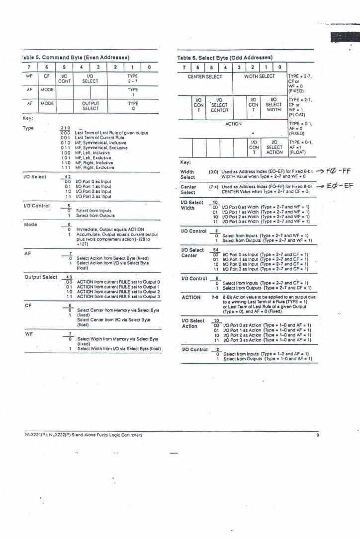
rable 5. Command By\e (Even Addreuu)
7 6 5 4 I 3 2 I 1 I 0
Wf CF 110 1/0 TYP£ CONT SELECT 2 - 7
AF MOOE l TYPE I
AF MOOE OUTPUT TYPE SELECT 0
Key:
Type 210 000 Last Tm mol Last Rule ol given output 001 La~t Tetm of Cutrent Rule 010 MF. Synmetrical, L'lCiusive 011 MF, Syrrmetrical, Exclusive 100 MF. Left . Inclusive 101 MF. Leh. Exclusive 110 MF. Right, lnc;IU$ive 111 MF, Right. Exclusive
UO Select 0 0~ 1/0 Port 0 as Input 01 1/0 Port 1 as Input 10 1/0 Port 2 as Input 11 110 Port 3 as Input
UO Control 5 -0- S.-!lectlrom Inputs
1 Select I rom Outputs
Mode 6 -0- lnvnediata, Output equals ACTION
1 Accum.Jiate. Output equals current output plus two's c~lement 1ction (· 128to +127)
AF 1 --0 Select Action from Select Byte (lixed)
1 Select Action lrom 110 via Select Byte (flOat)
Output Select 43 00 ACTION from Cutient RULE set to Output 0
01 ACTION from cut rent RULE set to Output 1 10 ACTION from cutrent RULE set to Output 2 11 ACTION lrom current RULE set to Output 3
CF I -0- Select Center from MetT'()Iy vie Select Byte
1 (fixed) Select Centertrom VO via Select Byte (ltoat)
WF 1 -0- Select Width from Mem:xy via Select Byte
(lixed) Select Width lrom 110 via Select Byte (ltoat)
NlX22 1(P). NLX222(P) Stand-Alone Fuzzy logic Controllers
Table S. Select By\e (Odd Addreuea)
7 6 s 1 4 3 2 1 I 0
CENTER SELECT WIDTH SELECT TYPE • 2·7,
vo CON
Key:
Width Select
Canter Select
T
VO Select Width
CFor WF •0 (FIXED)
110 l/0 vo TYPE • 2·7. SELECT CON SELECT CF or CENTER T WIDTH WF • 1
(FLOAT)
ACTION TYPE·0.1. AF •0
4 (FIXED)
1/0 110 TYPE • 0.1, CON SELECT AF •1
T ACTION (FLOAT)
(3 :0) Used as Address Index (EO-tF)Ior Fixed 6-bit -? frP - ff WIDTH Value when Type • 2-7 and WF • 0
(7 :~) Used as Address Index (FO-FF)Ior Fixed 8-bit ~ E.C/;- E'F CENTER Value when Type • 2-7 and CF • 0
10 (X) 110 Port 0 as Width ('Type • 2-7 and Wf = 1)
01 t/0 Port1 as Width (Type • 2-7 and WF • 1) 10 110 Port 2 IS Width (Type • 2-7 and WF • 1) 11 110 Port 3 as Width (Type • 2-7 and WF • 1)
UO Control 2
UO Select Centar
-0- Select from Inputs (Type • 2-1 and WF • 1) 1 Selectlrom Outputs (Type • 2-7 and WF • 1)
54 (X) 110 Port 0 as Input (Type • 2-7 and CF • 1)
01 110 Por11 as Input (Type" 2-7 and CF • 1) 10 110 Port2 as Input (Type • 2-7 and CF • 1) 11 110 Port3 as Input (Type • 2-7 and CF • 1)
VO Control 6
ACTION
VO Select Action
VO Control
-0- Select from Inputs (Type • 2-7 and CF • 1) . 1 Setectlrom Outputs (Type • 2-7 and CF • 1)
7-<1 8-B~ Action v1tueto be appfied to an output due to 1 wming Last Term of a Rule (TYPE • 1)
10
or Last Term ollas1 Rule ol a given Output (T)'pa • 0). 1nd AF • 0 (Fixed) .
CX>IIO Pori 0 as Action {Type • 1~ and AF" 1) 01 110 Port 1 as Action (Type • 1~ and AF • 1) 10 VO Port 2 as Action (Type • 1~ and AF • 1) 11 110 Port 3 as Action (Type • 1~ end AF • 1)
2 -0- Select from Inputs (Type • 1~ end AF • 1)
1 Select from Outputs (Type • 1~ and AF • 1)
9

The Type code Last Fuzzy Variable .(001) signals th:~t the l:lst fuuy variable of the rule has been processed. When this occurs, only the two most significant bits (MSB) of the five-bit field are used. The MSB selects whether the action value comes from a fixed memory location or from an VO latch. The next MSB speeifies the output mode. immediate or accumulate. ·
The code (000) indicates Last Fuuy Variable of Last Rule. The two most signific:111t bits are used as described in the p:~n graph above. In iddition, the two bits above the Type Select field are used to select the output.
The second byte always occurs on ll1l odd address, and contains the Center and Width address index fields if the previous byte specified a membership function type IJld fixed center and width values. If either the center ·or the width were speeified a.' floating, then their respective nibble in the odd byte is used to select the input or output
When the first byte's Type is Last Fuuy Variable or L:!st Fuuy Variable of Last Rule IJld the action is fixed, the second byte conuiru the action value. If action is floating, then the odd byte selects the input or output that provides the action value.
Tlmlng
Figure 12 illustrates VO timing for the devices. The three architectural blocks that impact timing include the multiplexed input sampling, the fuuy controller, and the multiplexed output D}A converter.
Processing speed is a function of the clock r:1te and the number of clocb (1024) required to complete data sampling and processing cycles. The cloclc maximum rate is 10 MHz and the minimum is I MHz.
Operating Timing
Reset When the RESET pin is active all the l:l.tches ~e clea.red, the digilAI outputs a.re logic low, IJld the NLX222 analog outputs hold at the level they were at prior to the assertion of reset If RESET is 11ctive for one hundred clocks or more, the analog inputs wi.ll be zero when sampling resumes. - If RESET is active for less thiJl one hundred clocb, there may be some residual of the last 11mpled data still present on the analog inpuiJ when sampling resumes. When RESET is deacti· vated, the device bcgiru sampling inpuiJ during the first I 024 clock cycle.
VO Selection Code Input umpling and output upd11ting a.re time division multiplexed. The AS (I :0) bus specifies the source and destination of data according to the following code:
vo AS1 ASO 0 0 0 1 0 1
2 I 0 3 I I
10 ·'
Figure 12. VO Timing
• g ~ i
. !
I 2 - "
!. ~
1 !
I d " G ~
! i g i i I ... !-~J - " . : .
~ !
~ -~ ;j
I ~
" § 0
d I .. !
§ ~
• d ;j
! I
~ g .. i
5 I
E
! ~ -5 I i -
! " a I
-· '-1
~
NLX221(P). NIX222(P) StMd·Aiorle Fuzzv logic Controllers
" dat bu:
Dl! is : '\lo'~
ou
Nl n or c~
~
fo, di sh
Fl
lr ir l i \1
tt · ${
c s lc p t b n

r
Digitalin put Data 1iming for sampling digiul input d~12 is ~hewn in Figure 13 . The rising edge of snOBE shows when d~ta must be v~lid for sampling the input addressed by the AS bus.
Digital Output Data Timing for umpling digital output data is shown in Figure 14. The falling edge of STROBE indicates ,.·hen output data is valid. The STROBE can be used to latch output data in an external dnice sdected by the AS bus.
NLX222 VO Data Sourc6 Sel~ctlon and Converalon The !'-ILX222 allows for any input channel to be either analog or digital data. Output d~ta is always available as analog and c~n :~lso ap~ digitally. The INSEL pin selects whether the source of d:~ta for an input umple is analog or digital. Timing for when INSEL must be a.s..cned (h igh for analog. low for digital) is based on when the STROBE signal is active as shown in Figure I 3.
Figure 13. Time Dlvlalon Multiplexed Input Timing
AStiO!~~ STROU _IL ___ .....Jn._ ___ _ INS(l
011101~
Input an:~log values arc converted to digital data and latched internally in successive periods of 256 clocks each. A total of· I 024 clock cycles are required to convert all four inputs after which the conversion process rcpats. At the maximum clock, the sampling rare for each input is 10 KHz. or 100 microseconds.
IJutput <hlta always appears on the analog outputs. The OUTSEL pin selects whether the SC'urce of data for an output is analog only or also digital as shown in Figure 14. If the OUTSEL pin is low, the d:~ra is also latched internally and passed io the DO bus. 1iming for when OUTSEL must be asserted (low for both, high for analog only) is b~sed on when the STROBE sign~l is active.
Figure 14. Time Division Muitlplexed Output Timing
ASt i .O)
STAOIIE ----.lr--lL. ___ ..Jr-1,_ ___ _
OUTSEl
NLX221(P). NLX222(P) StanCl ·Alone Fuzzy Logic ContrOllers
NLX222 Fixed Mixed Signal Operation The CH3 signal alone can be used as an ahcrn:~tivc to the A_S hus si~:nals for applications requiring three analog VO and one digital VO channel. The fixed mode oper~tion saves external hardware because it doesn't require address decoding. II can be connected to OUTSEL to control the output source or to INSEL to select analog or digital inputs. 1iming is shown in Figure I 5.
Figure 15. Output Timing Using CH3 Option
eKl
STROe{ n n 00(70) -< VAllO OATA )
AS tiD)
AOUT 10. I . 21 < VAllO OA.TA >-AOUTl --< VAllO OATA )
Controller Timing
T!ie first I 024 dock processin"g ·cycle begins :~fler the first input conversion cycle has completed. Processing cydcs consist of I 024 clock cycles regardless of the number of fuzzy v:u-i;blcs ;md rules used.
Fuuy v~ri~ble and rule evalu~tions require four clocks each. For example, a rule with two fuzzy variables would require 12 clocks to process. During a processing cycle either a fuzzy vari11blc or rule is being processed each four-clock period, except for a 64-clock l:~tency period at the end of the processing cycle . .
Internal Loopback Delay
When d:~ta in the output latch is internally looped back a.s inpuu, they lag the analog inputs by the I 024 clocks of the initiAl sampling cycle. After that, as the output latches arc updated during processing the data feedback is used as inputs.
' Output Timing
Outpuu arc updated on successive 256-byte bound:u-ies after processing begins as shown in Figure IS. Each output pin is upd:~ted once every 1024 clocks. Output update timing is l:~rgcly invariant.
Output l:~tches are updated immediately after a relevant rule evaluation is complete.
11

Prescaled Operation
The device contains :1 lo:~d:~ble, eiJ;ht-bit presc:~le counter th:~t nllows it to be in:~ctive for periods of time. The fe:~lure is used to ":ITY the r:1tes of nmpling :1nd processing. The last loc:~tion in the memory, which norm:~lly stores !ixed membership function width d:~t:1, m:~y inste:~d store . :~ value to be lo:~ucd into the counter. Tite PRESCALE pin selects norm:~l or prcsc:~lcd opcr:~tion.
In presc:~le mode, the controller is in:~ctive for periods of I 024 clocks :1fter which the counter is incremented. When the counter rolls over, the controller is :~ctiv:~ted for :1 single 1024 clock period to perform fuzzy comput:~tion: :~nd the counter is loaded ag:~in. Outputs rem:~in unch:~ngcd during periods of in:~ctivity.
You set the sc:~ling by entering the complement of the number of 1024 clock interv:~ls you wish hctwcen s:~mpling :~nd pro·
Figure 16. Package Mechanical Details
NLX221(P)
.+.. .050'" • .oos· ....
. o1ra~
ccssins cycies. For cx:~mple, you spccif)· s:~mpling sep:u:tlcd hy t'oi."O intervals by entering FD. Presc:~lc intcrv:~ls are entered during compil:~tion of the design file.
llte pin can be tied low \l."hcn not used or tied to the READY pin for continuous prcsc:~lc operation. E:ottcm:~l logic c:m :~lso be used to opcr:~te the pin :~llowir.g the prcsc:~lc futiction to he
. :ISScrtcd or not during different periods of oper:~tion.
Inactive Mode
Power consumption c:~n be reduced from th:~t of th.: opcr:~tinl! mode to st:~ndby mode by holding the clock pin hiJ;h. Stopping the clock suspends proceHing and IC:I\'CS digital outputs :It their l:~st seuinJ:. An:~log outputs will lc~k to 1eru o,·cr time. Processing continues when the cl01.:lc 'resumes. \\'hilc the· cl01.:k is stopped it should
4hc held :~!logic lc:vcl nne .
·,
NLX222(P)
.b50" • .ros·
l -11-- 029 • =·
N~ural.otiz rtSU\'tJ th~ right tu makt clklnltS In this docum~nl witluml •wtirr.
-
I
"' ~ ! .
..
l 1 J

i
RIWAYAT HIDUP
Penulis lahir di Surabaya, 17 Nopember 1968 dengan nama SY AIFUL SY AHRI
terlahir sebagai anak ke lima dari lima bersaudara, dari Bapak M.ANAFIE dan
Ibu SALAMAH. .Pendidikan fonnal yang telah ditempuh yaitu: Sekolah Dasar
Negeri Waru I tahun 1976 - 1982, Sekolah Menengah Pertama Negeri Waru I
tahun 1982 - 1985, Sekolah Menengah Atas Negeri Taman tahun 1985 - 1988,
Politeknik Universitas Brawijaya Malang Jurusan Teknik Listrik tahun 1988 -
1991 , Institut Teknologi Sepuluh Nopember Surabaya tahun 1994 - 1997.
Penulis pemah kerja sebagai pegawai di PT. WIJA YA KARYA tahun 1992 -
1994.
Related Documents