I AUTOMATIC LIGHT / FAN CONTROL SYSTEM FOR AUDITORIUM This project report submitted in partial fulfillment of the requirements for the Award of Degree of Bachelor of Science in Electrical and Electronic Engineering Submitted By Sujon Chandrasil ID: 151-33-2568 Zakir Hosen ID: 151-33-2563 Supervise By Dr. Md. Rezwanul Ahsan Assistant Professor Department of Electrical and Electronic Engineering Faculty of Engineering Department of Electrical and Electronic Engineering Faculty of Engineering DAFFODIL INTERNATIONAL UNIVERSITY December 2018 ©Daffodil International University

Welcome message from author
This document is posted to help you gain knowledge. Please leave a comment to let me know what you think about it! Share it to your friends and learn new things together.
Transcript

I
AUTOMATIC LIGHT / FAN CONTROL SYSTEM
FOR AUDITORIUM
This project report submitted in partial fulfillment of the requirements for the Award of
Degree of Bachelor of Science in Electrical and Electronic Engineering
Submitted By
Sujon Chandrasil
ID: 151-33-2568
Zakir Hosen
ID: 151-33-2563
Supervise By
Dr. Md. Rezwanul Ahsan
Assistant Professor
Department of Electrical and Electronic Engineering
Faculty of Engineering
Department of Electrical and Electronic Engineering
Faculty of Engineering
DAFFODIL INTERNATIONAL UNIVERSITY December 2018
©Daffodil International University

ii
©Daffodil International University

iii
Dedicated
To
Our Parents & Teachers
©Daffodil International University
iv
CONTENTS LIST OF FIGURES Vii
LIST OF ABBREVITIONS viii
ACKNOWLEDGEMENT ix
ABSTRACT x
CHAPTER 1 INTRODUCTION 11-13
1.1 Introduction 11
1.2 Purpose of the project 11
1.3 Scope of the Project 12
1.4 Problem Statement 12
1.5 Expected Project Out come 13
CHAPTER 2 OVERVIEW OF THE PROJECT 14-16
2.1 Introduction 14
2.2 Automatic Light Control 14
2.3 Automatic Temperature Controlled Fan Using Thermistor 14
2.4 Automatic. Fan Speed Control System Using
Microcontroller PIC16F72
15
2.5 Fire Detector 15
2.6 Automatic Visitor counter 15
CHAPTER 3 HARDWARE COMPONENT 17-39
3.1 Component and Accessories 17
3.2 Buzzer 18
3.3 Power supply 18
3.4 Voltage Regulator 19
3.5 Light Dependent Resistor 20
3.6. Resistor 21
3.6.1 Variable Resistor 22
3.6.2 Tips for Reading Resistor Code 23
©Daffodil International University

v
3.6.3 Resistor Color Code Chart. 23
3.6.4 Four Band Resistor 24
3.6.5 Five Band Resistor 25
3.7 Capacitor 25
3.7.1 The Capacitance of a Capacitor. 26
3.7.2 Standard Units of Capacitance 26
3.8 Diode 26
3.9 LED 28
3.9.1 Types of Light Emitting Diodes 28
3.10 LCD 29
3.11 Battery 29
3.11.1 Introduction of battery 29
3.12 IR Transmitter 30
3.13 IR Receiver 31
3.14 Temperature Sensor 31
3.15 Connector 32
3.16 Oscillator 32
3.16.1 Application 33
3.17 OP-Amplifier 33
3.17.1 Application 33
3.18 Microcontroller 33
3.18.1 Programmable Integrated Circuit 35
3.18.2 PIC16F72 Microcontroller 35
3.18.3 Pin Diagram 35
3.19 Circuit Diagram 37
3.20 Block Diagram 37
3.21 Cost Estimate 38
CHAPTER 4 DSIGN AND IMPLEMENTATION 40
4.1 Design 40
©Daffodil International University

vi
CHAPTER 5 RESULT AND DISCUSSION 41
5.1 Result 41
5.2 Discussion 41
CHAPTER 6 CONCLUSIONS 42
6.1 Conclusion 42
6.2 Limitations of the Work 42
6.3 Future Scopes 42
Reference 43
Appendix A 44-48
©Daffodil International University

vii
LIST OF FIGURES Fig 2.5 Fire Alarm System Block Diagram 15
Fig 3.2 Buzzer 17
Fig 3.3 AC to DC Converter Power supply 18
Fig 3.4 Pin Diagram of IC 7805 19
Fig 3.5(a) LDR 20
Fig 3.5(b) Symbol of LDR 21
Fig 3.5(c) Practical LDR 21
Fig 3.6 Resistor 22
Fig 3.6.1 Variable Resistor 22
Fig 3.6.3 Color code chart of Resistor 24
Fig 3.6.4 4-Band Resistor Color Code 24
Fig 3.6.5 5-Band Resistor Color Code 25
Fig 3.7. Electrolytic Capacitor 25
Fig 3.8 Diode 26
Fig 3.9(a) LED Function 28
Fig 3.10 LCD Display 29
Fig 3.11.1 Battery 30
Fig 3.12 IR Transmitter LED 31
Fig 3.13 IR Receiver 31
Fig 3.14 Temperature sensor 32
Fig 3.15 Connector 32
Fig 3.17 OP –Amplifier comparator mode working 33
Fig 3.18 PIC6F72 Microcontroller Chip 34
Fig 3.18.2 Pin Diagram of PIC16F72 Microcontroller 35
Fig 3.19(a) Circuit Diagram of Automatic light intensity control and
temperature control fan
37
Fig 3.19(b) Circuit diagram of automatic light control 37
Fig 3.20 Block Diagram of Automatic light control and temperature
control fan
©Daffodil International University
38

viii
List of Abbreviations
DC Direct current
AC Alternating Current
LED Light emitting Diode
LCD Liquid Crystal Display
LDR Light Dependent Resistor
nF Nano Farad
pF Pico Farad
mF Micro Farad
IR Infrared Ray
©Daffodil International University

ix
ACKNOWLEDGEMENT
First we express our heartiest thanks and to Allah for his divine blessing makes up possible
to complete this project successfully. we are grateful and wish our proud our indebtedness to
Assistant Professor Dr. Md. Rezwanul Ahsan, Department of Electrical and Electrical
Engineering, Daffodil International University, Dhaka. Deep theoretical and hardware
knowledge & keen interest of our supervisor in this field influenced us to carry out this
project. His endless patience, scholarly guidance ,continual encouragement, constant and
energetic supervision, constructive criticism, valuable advice, reading many inferior draft and
correcting them at all stage have made it possible to complete this project.
©Daffodil International University

x
ABSTRACT A microcontroller is used to obtain values of physical conditions through sensors connected
to it. In the automatic lamp system required sensors to detect the light of the LDR (Light
Dependent Resistor) sensor. This is because the light intensity received by the existing LDR
sensor in the room is blocked by the wall of the house or by other objects. Then for the fan, it
can also turn on automatically when the temperature is greater than 27°c,28°C, and the fan
speed can also be adjusted. The fan may also turn off automatically when the temperature is
less than equal to 27°C,28°C it also can be used automatically fire detector and automatically
visitor counter shown in the LCD display controlling by the sensor.
©Daffodil International University
11
CHAPTER 1
INTRODUCTION 1.1 Introduction. The principle behind this is very simple that is to turn Manually high and to turn off the fan
when temperature is low this is achieved which increases or decreases the resistance value.
This method is innovative saves most of the time and energy contr is And this way of using
becomes inefficient when the temperature has to be monitored over long time ranges So a
new method of automatic control of fan speed using the the wastage temperature sensors.
on the fan when temperature can be achieved Conventionally used fans speed can be
controlled by using the regulators which is the old and burdensome method. Develop a
product that can control the speed of the fan based on temperature the Room . IR and photo
diode and LCD.IR sensor is continuously emits the signal and photo diode is observes.
The microcontroller one and when any one leaves the room then the Counter is Decremented
by does the above job it receives the signals from the sensors. and photo diode is observes the
signal if any obstacles comes in between the IR and PHOTO diode This project consists of
micro controller, IR and photo diode and LCD.IR sensor is continuously emits the signal the
output of the photo diode is given to the microcontroller the count value is shown on LCD
©Daffodil International University
12
1.2 Purpose of This Project. automatic light control and we started our project, our first target was to fix the goal We have
been attracted to this project that contribute to the modern society there are many auditorium
in Bangladesh where electricity is wasted manual ways as the lights are on but there is no
man on the other hand the fans are control by temperature. the fans are automatic
ontemperature control fan,visitor countering lcd display Fire detector in a auditorium based
such and also used fire detector for fire safety .This project is low cost with effective and on
the other hand we used digital visitor counter which is used for counting present visitor
shown LCD display competitive usage.to be further This system is designed to be more users
friendly and automatic to operate These systems are directed at specific applications is made
to rotate at a speed proportional to the power The project has also been designed working
vision using minimum hardware at the lower level of processing..
1.3 Project Scope
The smart auditorium .Auto room light with bi directional automatically turn on the light in
a room when a person enters the room and turn it when the integral part of the Automatic
Room Lighting circuit. We modified the project with LEDs man leves the auditorium.
Dubbed the project as a bidirectional visitor counter it is an and as increase the person than
the light brightness is increase. Then used an LCD screen to monitor the temperature , visitor
counting The coding was design in. microcontroller The reading of microcontroller will be
compared to other monitoring system
1.4 Problem Statement
In other words, manual systems are In today’s world, many institutions are composed of
plenty of commercial buildings in one has to switch the auditorium lights and fan on and off.
A person can also forget to put off the which room light and fan are not automatically
controlled at all. employed in many buildings where lights and fan when leaving the
auditorium to numerous institutions, companies, and government agencies. The ability to
automatically control light and fan would allow This In operation to control these,
©Daffodil International University

13
this project herein, explores an automated auditorium light and fan controlling system to
curb the stemming challenge would further aid in the use of such systems by those who are
sick, handicapped or elderly the users to feel comfortable without physically controlling
them. The use of automated control here
1.5 Expected Project Out come Temperature At the to monitor the auditorium ,light intensity ,fire detector, visitor counter
using Microcontroller. This is an efficient program for a smart auditorium end of this
project, suitable coding for Microcontroller can be made. Hence, the user will be able.
©Daffodil International University

14
CHAPTER 2
OVERVIEW OF THE PROJECT 2.1 Introduction. carefully . Automatic auditorium microcontroller based project automatic light on and off
system and the fan auditorium By using this on or off the lights in a auditorium Electricity,
being one of the most important resources, must system, we can intentionally forget about the
lights as the system will automatically take care of perform certain tasks. and fans.The most
essential electronic device at home or auditorium or any other place automatically reducing
human efforts, improving standard of living etc. the auditorium where there is a chance of
fire accident is a fire alarm circuit. where by using the fire alarm circuit, we can avoid
financial loss and also save people from dangerous fire accidents the microcontroller
2.2 Automatic Light Control is important as it will determine the functioning of the project .The sensor placed on the row-
1 of the sensors is named as Sensor 1 and the sensor, which is placed on the row 2 is named
Sensor 2.and IR Sensor and we have used three of them. The placement of the 1 detects the
Sensor auditorium The main person first and then Sensor 2.and then sensor 3 This action will
indicate the OP-Amplifier that the person is entering in the row 1,2,and 3. the sensor, which
is placed on the row-3 is named Sensor 3 When a person tries to enter the room, component
of the project is
2.3Automatic Temperature Controlled Fan Using Thermistor a type of transducer. In a broader In this paper for sensing the temperature Thermistor has
been used. Here also described that be controlled, based on temperature sensor.
A sensor is sense, a transducer is sometimes how the speed of a fan can defined as any device
that converts energy from one form to another. Besides that, the component that made up the
temperature. it can also be used to control the auditorium temperature, depending on the
property of Thermistor sensor is known as Thermistor.
©Daffodil International University
15
Thermistor is a kind of temperature dependent resistor and its resistance varies depending on
the temperature
2.4Automatic.Fan Speed Control System Using Microcontroller PIC16F72 Controlling system are main part of the microcontroller.LM35 sensor has been used for
sensing.Microcontroller has been used instead of hard wiring a number of logic gates together
to perform some function use instructions to wire the gates electronically. The list of these
instructions Microcontroller has been used instead of hard wiring a number of logic gates
together to perform given to the microcontroller is called a program.
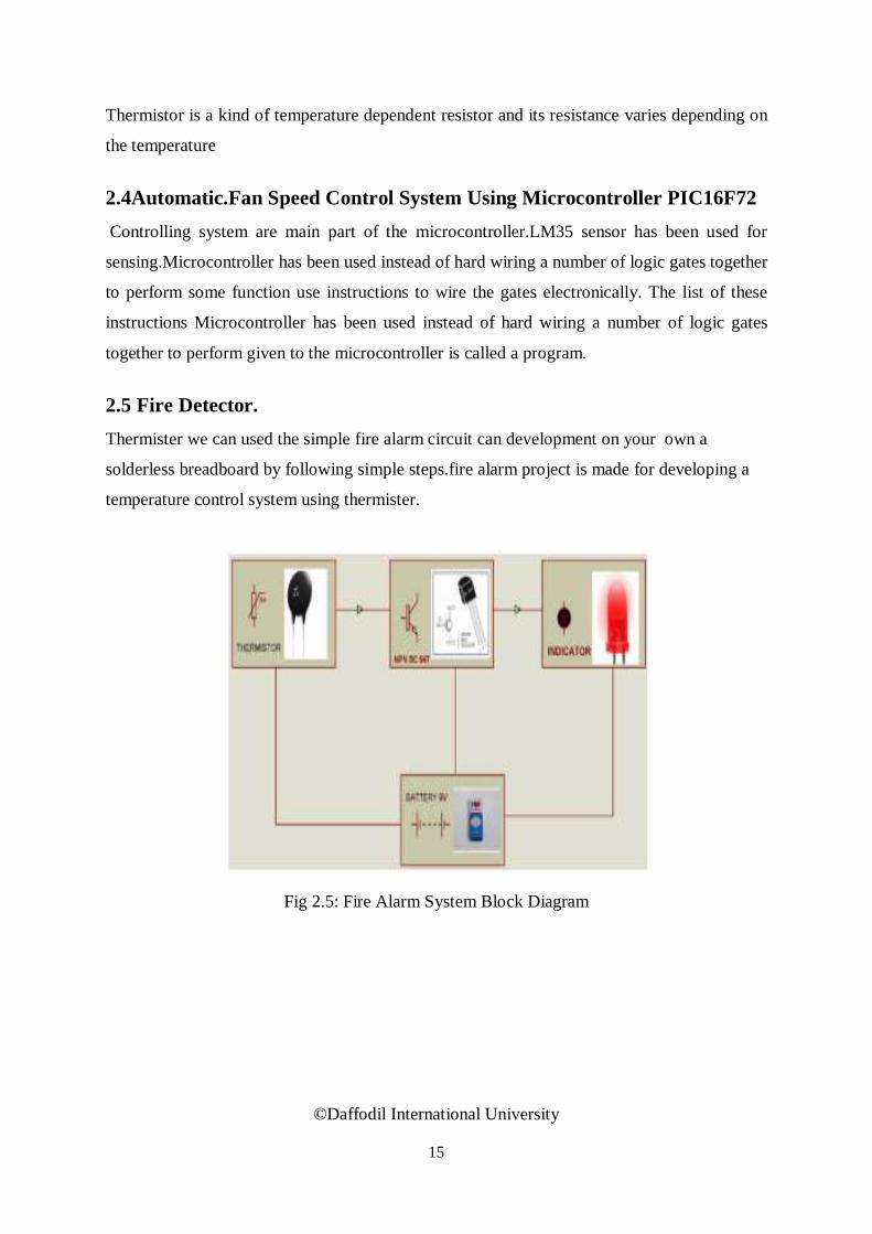
2.5 Fire Detector. Thermister we can used the simple fire alarm circuit can development on your own a
solderless breadboard by following simple steps.fire alarm project is made for developing a
temperature control system using thermister.
Fig 2.5: Fire Alarm System Block Diagram
©Daffodil International University
16
2.6 Automatic Visitor counter. is Decremented by When somebody enters into the Room then the Counter is Incremented by
one and when any One.Digital over the task of counting one leaves the room then the Counter
visitor counter is a reliable circuit that takes Number of Persons/ Visitors in the Room very
accurately.The total number of Persons inside the Room is displayed on liquid crystal
displays.. This project consists of micro controller, IR and photo diode and LCD.IR sensor is
continuously emits the signal and photo diode is observes the signal if any obstacles comes in
between the IR and PHOTO diode the output of the photo diode is given to the
microcontroller the count value is shown on LCD.
©Daffodil International University

17
CHAPTER 3
HARDWARE COMPONENT 3.1 Component and Accessories LCD DISPLAY
MICROCONTROLLER PIC 16F72
CAPACITORS
RESISTOR
DIODE
BUZZER
CONNECTOR
AC POWER SUPPLY
SOME WIRES
PCB BOARD
SWITCH
LED
LDR SENSOR
IR SENSOR
DC BATTRY
OP-AMPLIFIER
TEMPERATURE SENSOR
©Daffodil International University
18
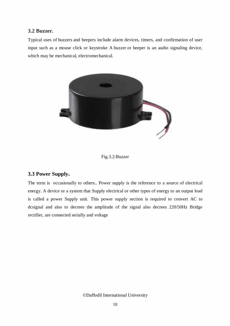
3.2 Buzzer. Typical uses of buzzers and beepers include alarm devices, timers, and confirmation of user
input such as a mouse click or keystroke A buzzer or beeper is an audio signaling device,
which may be mechanical, electromechanical.
Fig.3.2:Buzzer
3.3 Power Supply. The term is occasionally to others.. Power supply is the reference to a source of electrical
energy. A device or a system that Supply electrical or other types of energy to an output load
is called a power Supply unit. This power supply section is required to convert AC to
dcsignal and also to decrees the amplitude of the signal also decrees 220/50Hz Bridge
rectifier, are connected serially and voltage
©Daffodil International University

19
Fig.3.3:AC to DC Converter Power Supply
3.4 Voltage Regulator. Usually, we start with an unregulated power supply ranging from 9volt to 12volt DC.
To make a 5volt power supply, IC 7805 voltage regulator as shown in figure has been used.
Fig. 3.4: Pin Diagram of IC 7805
ns the output voltage at Voltage sources in a circuit may have fluctuations resulting in not
providing fixed voltage outputs. 7805 IC provides +5 volts regulated power supply voltage
regulators used to maintain such fluctuations, is a popular voltage regulator integrated circuit
(IC). with provisions to add a heat sink.
©Daffodil International University

20
3.5 Light Dependent Resistor.
The power ratings are usually smaller and are in the range 50mW to 0.5W. Though very
sensitive to light, the switching. In the absence of light the resistance can be in the order of
10K ohm to 15K ohm and is called the dark resistance. time is very high and hence cannot be
used for high frequency applications the resistance decreases They are used in chopper
amplifiers. Light dependent resistors are available as disc 0.5cm to 2.5cm. The resistance
rises to several Mega ohms under dark conditions.The below figure shows that when the
torch is turned on, the resistance of the LDR falls, Depending on the exposure of light the
resistance can fall down to value of 500 ohms.. allowing current to pass through it is shown
in figure.
Fig. .3.5(a):LDR.
©Daffodil International University

21
Fig. 3.5(b): Symbol of LDR
The basic construction and symbol for LDR are shown in above figures respectively. The
device consists of a pair of metal film contacts separated by a snakelike track of
Fig. 3.5(c): Practical LDR
cadmium sulphide film, designed to provide the maximum possible contact area with the two
metal films. The structure is housed in a clear plastic or resin case, to
3.6 Resistor.
adjust signal levels, to divide voltages, bias active elements, and terminate transmission lines,
among other uses . implements electrical resistance as a circuit element. In electronic
circuits, resistors are used to reduce current flow,.
©Daffodil International University
22
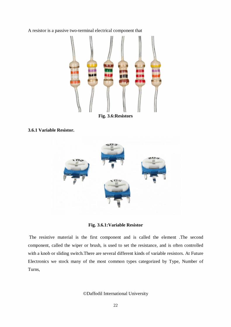
A resistor is a passive two-terminal electrical component that
Fig. 3.6:Resistors
3.6.1 Variable Resistor.
Fig. 3.6.1:Variable Resistor The resistive material is the first component and is called the element .The second
component, called the wiper or brush, is used to set the resistance, and is often controlled
with a knob or sliding switch.There are several different kinds of variable resistors. At Future
Electronics we stock many of the most common types categorized by Type, Number of
Turns,
©Daffodil International University

23
Variable Resistors can be Potentiometer, Trimmer or Turns Counting Dial type.Variable
Resistors can be found in:
Audio control
Television
Motion control
Transducers
Computation
Home Electrical Appliances
Oscillators
3.6.2Tips for Reading Resistor Code.
The4 give away the reading direction. Also, the first band is usually the reading direction
might not always be clear.) is always the last band. Sometimes the increased space
between band 3 and closest toa lead. A gold or silver band (the tolerance
It is a good practice to be the only way to figure out the resistance; for example when the
color bands are burnt off.check the manufacturer’s documentation to be sure about the
used
this might even
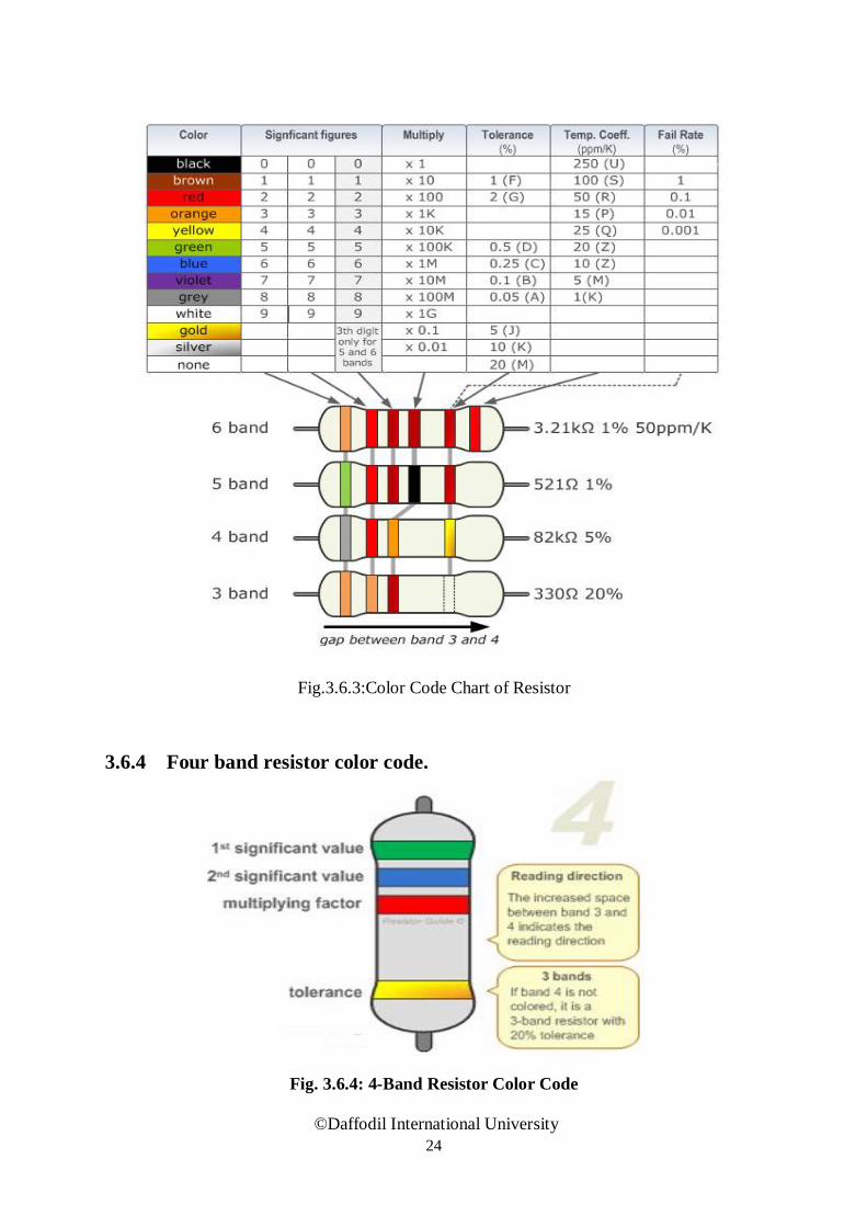
3.6.3 Resistor Color Code Chart.
The chart below shows how to automatic resistor calculator can be used to quickly find the
resistor values. determine the for resistors. The table can also be used to specify the color of
the bands when the values are known. An resistance and tolerance
©Daffodil International University
24
Fig.3.6.3:Color Code Chart of Resistor
3.6.4 Four band resistor color code.
Fig. 3.6.4: 4-Band Resistor Color Code
©Daffodil International University

25
3.6.5 Five band resistor
Fig.3.6.5: 5-Band Resistor Color Code
3.7 Capacitor.
There are many in the form of an electrical charge producing a potential difference (Static
Voltage) across its plates, much like a small different kinds of capacitors available. The
capacitor is a component which has the ability or “capacity” to store energy rechargeable
battery.
Fig. 3.7: Electrolytic Capacitor
3.8 Diode.
Diode use is flow the current .The diode made semiconductor material such as selenium .some diode is use rectifiers ,signal limiters, voltage regulators,switchand osilators modulators signal
©Daffodil International University

26
component with two electrodes called the anode and the cathode. are comprised of metal
electrodes in a chamber evacuated or filled A diode signal signal demodulators,with a pure
elemental gas at low pressure.
Fig. 3.8:Diode
3.9 Light Emitting Diode(LED).
A light-emitting diode (LED) is a semiconductor device that emits visible light when an
electric current passes through it. The output from an LED can range from red (at a
wavelength of approximately or longer); such a device is known as an infrared-emitting diode
(IRED).An LED or IRED consists . These two elements are placed in direct contact, forming
a region called the P-N junction. In this respect, the LED orIRED resembles most other diode
types, but there are important differences of two elements700 nanometers) to blue-violet
(about 400 nanometers). Some LEDs emit infrared (IR) energy (830 nanometers of processed
material called P-type semiconductors and N-type semiconductors. The LED or IRED has a
transparent package, allowing visible or IR energy to pass through. Also, the LED or IRED
has a large PN-junction area whose shape is tailored to the application.
©Daffodil International University

27
Fig.3.9(a):LED Function
3.9.1 Types of Light Emitting Diodes. Kinds of LED
Arsenide gallium
gallium Arsenide photoshide
There are different types of light emitting diodes present and some of them are mentioned
3.10 LCD.
Many type of LCD but here we use 16*2 display lcd that 16 character and 2 line
.
©Daffodil International University

28
Fig.3.10:LCD Display
3.11 Battery 3.11.1 Introduction of battery
it to Batteries are often used in PV systems for the purpose of storing energy produced by the
PV array during the day, and to supply charge controller is used in these systems to protect
the battery from overcharge and over discharge PV systems are to operate (during the night
and periods of cloudy weather). Other reasons batteries are used in In most cases, a battery
charge controller is used in these systems to protect the battery from overcharge and over
discharge PV systems are to operate the electrical loads as needed PV array near its
maximum power point, to power electrical loads at stable voltages, and to supply surge
currents to electrical loads and inverters..
Figure 3.11.1: Battery
©Daffodil International University

29
3.12 IR Transmitter. Infrared Transmitter is a light emitting diode (LED) which emits infrared radiations. Hence,
they are called IR LED’s. Even though an IR LED looks like a normal LED, the radiation
emitted by it is invisible to the human eye.The picture of Infrared LED is shown below.
Fig. 3. 12:IR Transmitter LED
3.13 IR Receiver TSOP17XX receives the modulated Means it detects the IR which is es its output..
switching On and Off at the rate of 38Khz. TSOP’s output is active low Infrared waves and
changTSOP1740 etc.means its output is remains HIGH when there is no IR, and becomes
low when it detects.
Figure 3.13:IR Receiver (TSOP1738)
©Daffodil International University

30
IR radiation operates on particular frequency so that other IRs in the environment can’t
interfere, except the modulated IR of particular frequency. It has three pins, Ground, Vs
(power), and output pin.
3.14 Temperature Sensor.
Temperature sensor with is proportional to the temperature in zero degree and lm 35
precision ic.
Fig.3.14 :Temperature sensor
3.15 Connector.
A connector is a device used to join electrical circuits and are also referred to as electrical
connectors.
©Daffodil International University

31
Fig 3.15:Pic Connector
3.16 Oscillator.
Electrical oscillator is crystal oscillator that use the mechanical response of a polarizing and vibrating crystal oscillator.
3.16.1 Application.
Crystal oscillator is used to provide clock to micro-controller. Clock is used to carry all the
function that micro controller provides. You need not give any separate voltage because
the micro controller has dedicated pin which excites Crystal oscillator.
3.17 OP-Amplifier.
A voltage comparator is an electronic circuit that compares two input voltages and lets you
know which of the two is greater. It's easy to create a voltage comparator from an op amp,
because the polarity of the op-amp's output circuit depends on the polarity of the difference
between the two input voltages.
©Daffodil International University

32
Fig.3.17:OP –Amplifier comparator mode working
3.18 Micro Controller(PIC16F72).
A controller is used to control some process or aspect of the environment A Microcontroller
is a Microcomputer in a single Chip.. .A typical microcontroller application is the monitoring
a house. As the temperature rises, That means that a microcontroller chip includes If the
temperature goes above a certain threshold, the air conditioner is activated.a microprocessor
(CPU) as well as some often used peripherals the controller causes the windows to open.
©Daffodil International University
33
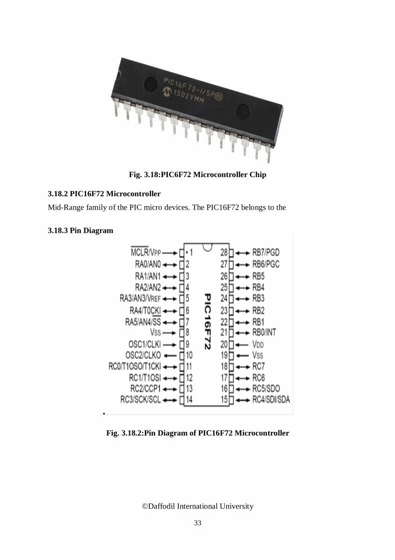
Fig. 3.18:PIC6F72 Microcontroller Chip
3.18.2 PIC16F72 Microcontroller
Mid-Range family of the PIC micro devices. The PIC16F72 belongs to the
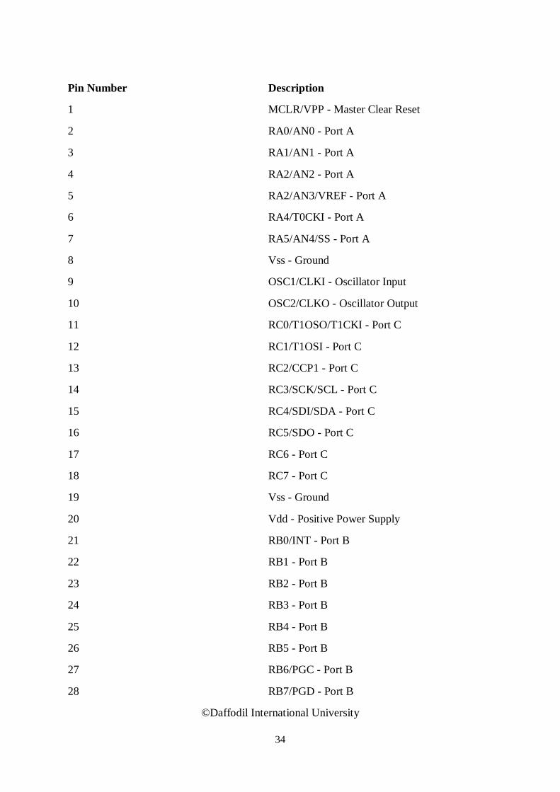
3.18.3 Pin Diagram
.
Fig. 3.18.2:Pin Diagram of PIC16F72 Microcontroller
©Daffodil International University
34
Pin Number Description
1 MCLR/VPP - Master Clear Reset
2 RA0/AN0 - Port A
3 RA1/AN1 - Port A
4 RA2/AN2 - Port A
5 RA2/AN3/VREF - Port A
6 RA4/T0CKI - Port A
7 RA5/AN4/SS - Port A
8 Vss - Ground
9 OSC1/CLKI - Oscillator Input
10 OSC2/CLKO - Oscillator Output
11 RC0/T1OSO/T1CKI - Port C
12 RC1/T1OSI - Port C
13 RC2/CCP1 - Port C
14 RC3/SCK/SCL - Port C
15 RC4/SDI/SDA - Port C
16 RC5/SDO - Port C
17 RC6 - Port C
18 RC7 - Port C
19 Vss - Ground
20 Vdd - Positive Power Supply
21 RB0/INT - Port B
22 RB1 - Port B
23 RB2 - Port B
24 RB3 - Port B
25 RB4 - Port B
26 RB5 - Port B
27 RB6/PGC - Port B
28 RB7/PGD - Port B
©Daffodil International University

35
3.19 Circuit Diagram.
Fig 3.19(a) : Circuit Diagram of Automatic light intensity control and temperature control fan
Fig 3.19(b): Circuit diagram of automatic light control
©Daffodil International University
36
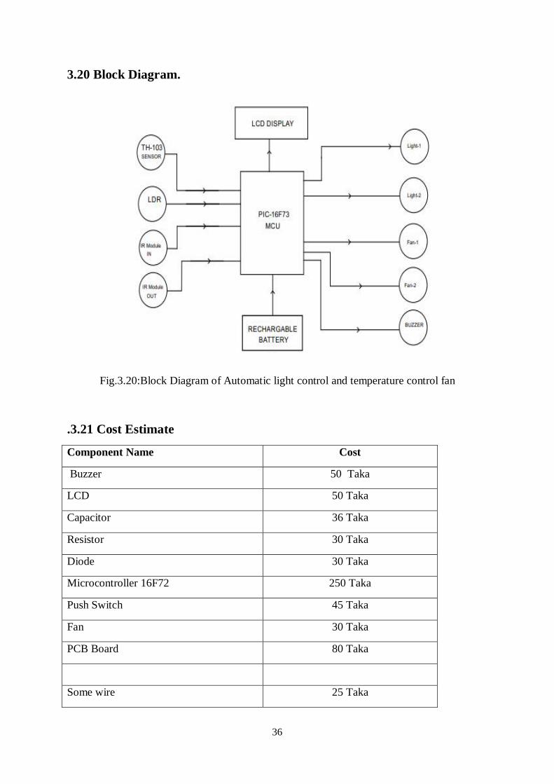
3.20 Block Diagram.
Fig.3.20:Block Diagram of Automatic light control and temperature control fan
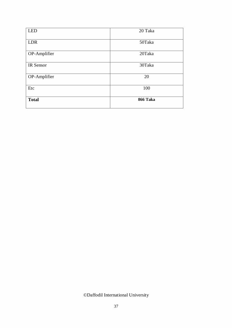
.3.21 Cost Estimate
Component Name Cost
Buzzer 50 Taka
LCD 50 Taka
Capacitor 36 Taka
Resistor 30 Taka
Diode 30 Taka
Microcontroller 16F72 250 Taka
Push Switch 45 Taka
Fan 30 Taka
PCB Board 80 Taka
Some wire 25 Taka
37
LED 20 Taka
LDR 50Taka
OP-Amplifier 20Taka
IR Sensor 30Taka
OP-Amplifier 20
Etc 100
Total 866 Taka
©Daffodil International University
38
CHAPTER 4
CONSTRUCTION AND DESIGN
4.1 Design.
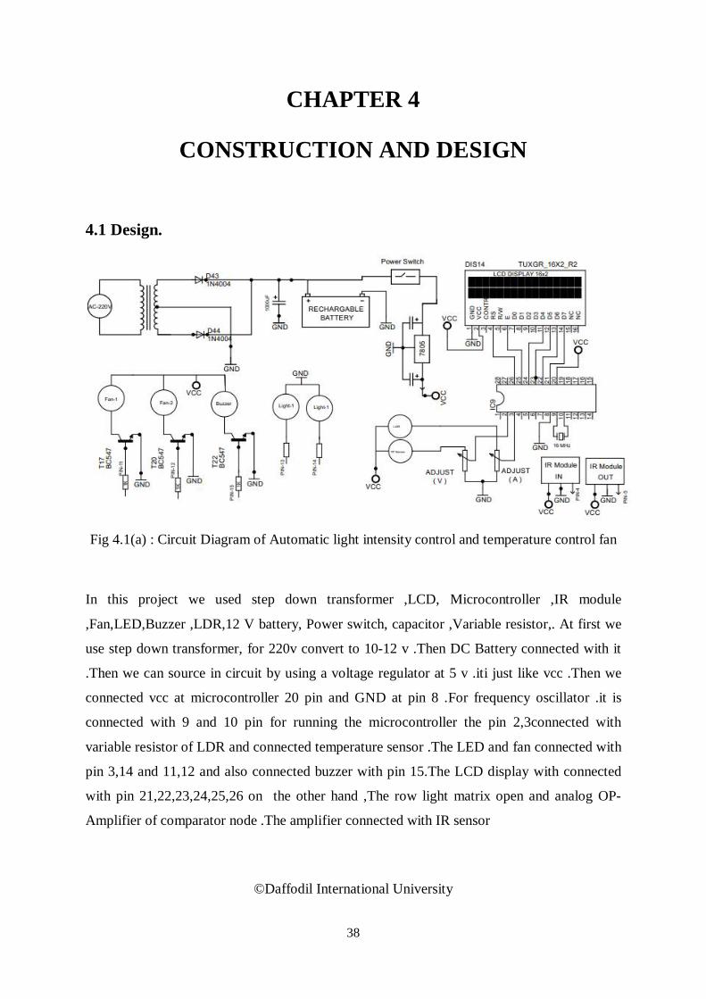
Fig 4.1(a) : Circuit Diagram of Automatic light intensity control and temperature control fan
In this project we used step down transformer ,LCD, Microcontroller ,IR module
,Fan,LED,Buzzer ,LDR,12 V battery, Power switch, capacitor ,Variable resistor,. At first we
use step down transformer, for 220v convert to 10-12 v .Then DC Battery connected with it
.Then we can source in circuit by using a voltage regulator at 5 v .iti just like vcc .Then we
connected vcc at microcontroller 20 pin and GND at pin 8 .For frequency oscillator .it is
connected with 9 and 10 pin for running the microcontroller the pin 2,3connected with
variable resistor of LDR and connected temperature sensor .The LED and fan connected with
pin 3,14 and 11,12 and also connected buzzer with pin 15.The LCD display with connected
with pin 21,22,23,24,25,26 on the other hand ,The row light matrix open and analog OP-
Amplifier of comparator node .The amplifier connected with IR sensor
©Daffodil International University

39
CHAPTER 5
RESULT AND DISCUSSION 5.1 Result. We are Properly connection do this project and finally we gate automatic auditorium lignt
intensity control ,and fan control depend on temperature we can easily seen our LCD Disply
auditorium in and out going
5.2 Discussion.
The number of person count and to microcontroller based. Model to count the number of
person interring to the auditorium and it lights up the auditorium based on the light intensity
and automatic light control of the auditorium and turn on fan automatically where the persons
are sitting inside the auditorium. It is made to prevent unwanted electric power waste in
schools, colleges, houses and other working places. This whole process is operated totally .
©Daffodil International University

40
CHAPTER 6
CONCLUSIONS
6.1 Conclusion. In this project, we develop a general purpose of electronic circuit design that can Show the
automatic light intensity control and fan control temperature based LCD display shown the
temperature and visitor counter it can be also used fire detector and alarm circuit This project
is the overview of smart auditorium system The project is successfully developed and met the
stated objectives.
6.2 Limitations of the Work. The working procedure of this project is very easy but we are facing some limitation for
doing this project. Such as coding problem, program writing, connecting to PCB board,
commend following etc
.
.
©Daffodil International University

41
REFERENCES
[1] A. K. Gupta, S. K. Arora (2007), Industrial Automation and Robotics, 348 pages, Laxmi
Publications, ISBN-10: 8131801810
[2] J. Burroughs (2010), “X-10 Home Automation Using The PIC16F877A” Lamp, vol. 10,
article 10
[3] F. J. Perez-Pinal, C. Nunez and R. Alvarez (2005), “A Novel Speed Control Approach In
Parallel-Connected Induction Motor By Using A Single Inverter And Electronic Virtual Line-
Shafting”, IEEE 36th Power Electronics Specialists Conference, (PESC '05), pp. 1339- 1345
[4] D.V. Nicolae and A. A. Jimoh (2007), “A Three-Phase Induction Motor with Power
Electronic Controlled Single-Phase Auxiliary Stator Winding”, IEEE Power Electronics
Specialists Conferences (PESC 2007), pp. 98-103
[5] A. M. Bazzi and P. T. Krein (2008), “Input Power Minimization Of An Induction
Motoroperating From An Electronic Drive Under Ripple Correlation Control”, IEEE Power
Electronics Specialists Conference (PESC 2008), pp. 4675-4681.
[6] D. A. Devi and A. Kumar (2012), “Design and Implementation of CPLD based Solar
Power Saving System for Street Lights and Automatic Traffic Controller”, International
Journal of Scientific and Research Publications, Vol. 2, Issue11, November 2012.
[7] David N. (2010), “Design of an Internet Based Security System”, NIJOTECH, Vol. 29
No. 2, pp. 118-129
[8] Reinhard Mullner, Andreas Riener (2011), “An Energy Efficient Pedestrian Aware Smart
Street Lighting System”, International Journal of Pervasive Computing and Communications,
Vol. 7, No. 2, pp. 147-161
[9] Vijaya Kumar, Kartthik Srinivas (2012), “Energy Eff
©Daffodil International University

42
APPENDIX A Programming code #include <16F73.h>
#fuses NOWDT, HS, PROTECT,NOBROWNOUT,NOPUT
#use delay (clock = 16000000)
#include <flex2_lcd.c>
#rom 0x3ff={0x3444}
#byte PORTA = 0x05
#byte PORTB = 0x06
#byte PORTC = 0x07
#byte TRISA = 0x85
#byte TRISB = 0x86
#byte TRISC = 0x87
#define SPORTA PORTA
#define SPORTB PORTB
#define SPORTC PORTC
#define FAN1 PIN_C0
#define FAN2 PIN_C1
#define LOD1 PIN_C2
#define LOD2 PIN_C3
#define BUZ PIN_C7
void setup(void);
void SETTINGS(void);
void LOD_CTRL(void);
void adc_read(void);
void lcd_show(void);
unsigned int COUNT,COUNT1,LDR,IR1,IR2,IN=0,OUT=0,TCNT,OCR,PF=0,PRESENT;
unsigned int1 UP=0,DN=0,SET=0,TOG;
float tp=0,TF=0;
///////////////////////////////////////////////////////////////////////////////
///////////////////////////////////////////////////////////////////////////////
©Daffodil International University

43
void main()
{
setup();
while(1)
{
LOD_CTRL();
////////////////////////////////
TCNT++;
if(TCNT > 50)
TCNT=0;
COUNT++;
if(COUNT > 250)
{
COUNT1++;COUNT =0;
adc_read();
}
if(COUNT1 > 50)
{ COUNT1 =0;TOG ^=1;lcd_show(); }
}
}
////////////////////////////////////////////////////////////////////////////////
////////////////////////////////////////////////////////////////////////////////
void setup()
{
TRISA=0b11111111;
TRISC=0b00000000;
TRISB=0b00000000;
setup_adc(ADC_CLOCK_DIV_32);
lcd_init();
output_HIGH(BUZ);delay_ms(70);output_LOW(BUZ);delay_ms(70);
output_HIGH(BUZ);delay_ms(70);output_LOW(BUZ);delay_ms(70);
output_HIGH(BUZ);delay_ms(70);output_LOW(BUZ);delay_ms(70);
lcd_gotoxy(1,1);
©Daffodil International University

44
printf(lcd_putc, " WELCOME TO ");
lcd_gotoxy(1,2);
printf(lcd_putc, " DIU ");
delay_ms(1500);
lcd_gotoxy(1,1);
printf(lcd_putc, " ");
delay_ms(500);
//setup_timer_1(T1_INTERNAL|T1_DIV_BY_1);
//enable_interrupts(int_timer1);
//ENABLE_INTERRUPTS(Global);
//SET_TIMER1(64854);
}
////////////////////////////////////////////////////////////////////////////////
void adc_read(void)
{
set_ADC_channel(0);
delay_ms(1);
tp = read_adc();
tp = tp * 0.2;
TF= 1.8 * tp +32;
set_ADC_channel(1);
delay_ms(1);
LDR = read_adc();
}
////////////////////////////////////////////////////////////////////////////////
void LOD_CTRL(void)
{
if( TP > 27 )
{
output_high(FAN1);
}
if( TP > 28 )
©Daffodil International University
45
output_high(FAN2);
}
if( TP < 27 )
output_LOW(FAN1);
output_LOW(FAN2);
}
if( TP > 40 )
{
unsigned int i=0;
for(i=0;i<10;i++)
{
adc_read();
lcd_show();
output_HIGH(BUZ);
delay_ms(100);
output_LOW(BUZ);
delay_ms(100);
}
}
////////////////////////////// VISITOR COUNTER
IR1 = input(PIN_A2);
IR2 = input(PIN_A3);
IF(! IR1)
{
OUT++;delay_ms(500);
}
IF(! IR2)
IN++;delay_ms(500);
}
PRESENT= ( IN - OUT );
//////////////////////////////////////
IF(PRESENT >= 1 )
{
©Daffodil International University

46
if( LDR < 40 )
{
if(COUNT ==2 )
{
if( LDR > 30 )
OCR++;
if( LDR < 30 )
OCR—
IF(OCR > 48) {OCR=48;PF=1;}
IF(OCR < 2) {OCR=2;PF=0;}
}
IF(TCNT > OCR)
{ output_HIGH(LOD1);output_HIGH(LOD2);}
ELSE
{ output_LOW(LOD1);output_LOW(LOD2);}
}
ELSE
{ output_LOW(LOD1);output_LOW(LOD2);}
}
ELSE
{ output_LOW(LOD1);output_LOW(LOD2);}
//////////////////////////////////////
}
//////////////////////////////////////
4void lcd_show(void)
{
lcd_gotoxy(1,1);
printf(lcd_putc, "T:%2.1f%cC ",TP,223);
lcd_gotoxy(10,1);
printf(lcd_putc, "P:%3u ",PRESENT);
lcd_gotoxy(1,2);
printf(lcd_putc, "IN:%3u OUT:%3u ",IN,OUT);
//printf(lcd_putc, "IN:%3u OUT:%3u ",IN,LDR);
} ©Daffodil International University
Related Documents