ARMY TM 5-6115-271-14 AIR FORCE TO 35C2-3-386-1 MARINE CORPS TM 05926A-14 NAVY NAVFAC P-8-613-14 TECHNICAL MANUAL OPERATOR, ORGANIZATIONAL, DIRECT SUPPORT AND GENERAL SUPPORT MAINTENANCE MANUAL GENERATOR SET, GASOLINE ENGINE DRIVEN, SKID MOUNTED, TUBULAR FRAME, 3 KW, 3 PHASE AC,120/208 AND 120/240 VOLTS,28 V DC (LESS ENGINE) DOD Model Hertz NSN MEP-016A 60 6115-00-017-8237 MEP-021A 400 6115-00-017-8238 MEP-026A DC 6115-00-017-8239 This copy IS a reprint which includes current pages from Changes 1 through 11 PUBLISHED UNDER THE AUTHORITY OF THE DEPARTMENTS OF THE ARMY, AIR FORCE, U.S. MARINE CORPS AND NAVY AUGUST 1976

Welcome message from author
This document is posted to help you gain knowledge. Please leave a comment to let me know what you think about it! Share it to your friends and learn new things together.
Transcript

ARMY TM 5-6115-271-14AIR FORCE TO 35C2-3-386-1MARINE CORPS TM 05926A-14NAVY NAVFAC P-8-613-14
TECHNICAL MANUAL
OPERATOR, ORGANIZATIONAL, DIRECT SUPPORT AND
GENERAL SUPPORT MAINTENANCE MANUAL
GENERATOR SET, GASOLINE ENGINE DRIVEN, SKID MOUNTED,
TUBULAR FRAME, 3 KW, 3 PHASE AC,120/208
AND 120/240 VOLTS,28 V DC
(LESS ENGINE)
DOD Model Hertz NSN
MEP-016A 6 0 6115-00-017-8237MEP-021A 4 0 0 6115-00-017-8238MEP-026A D C 6115-00-017-8239
This copy IS a reprint which includes current
pages from Changes 1 through 11
PUBLISHED UNDER THE AUTHORITY OF THE DEPARTMENTS OF THE ARMY, AIR FORCE,U.S. MARINE CORPS AND NAVY
AUGUST 1976

CHANGE
ARMY TM 5-6115-271-14AIR FORCE TO 35C2-3-386-1MARINE CORPS TM 05926A-14NAVY NAVFAC P-8-613-14
C 12
HEADQUARTERSDEPARTMENTS OF THE ARMY, NAVY AND AIR FORCE
NO. 12 AND HEADQUARTERS, U.S. MARINE CORPSWASHINGTON, D.C., 31 March 1993
Opera to r , Organ iza t iona l , Di rec t andGeneral Support Maintenance Manual
GENERATOR SET, GASOLINE ENGINE DRIVEN, SKID MOUNTED, TABULAR FRAME3 KW, 3 PHASE, AC, 120/208 AND 120/240 VOLTS, 28 V DC (LESS ENGINE)
DOD MODEL HERTZ NSN
MEP-016A 60 6115-00-017-8237MEP-016C 60 6115-00-143-3311MEP-021A 400 6115-00-017-8238MEP-021C 400 6115-01-175-7321MEP-026A DC 6115-00-017-8239MEP-026C 28 V DC 6115-01-175-7320
DISTRIBUTION STATEMENT A: Approved fo r pub l i c r e l ease ; d i s t r ibu t ion i s un l imi t ed .
TM 5-6115-271-14/TO 35C2-3-386-l/TM 05926A-14/NAVFAC P-8-613-14, 3 August 1976,is changed as follows:
1. Remove and insert pages as indicated below. New or changed text materiali s ind ica ted by a ve r t i ca l ba r in the marg in . An i l lu s t r a t ion change i sindicated by a point ing hand.
Remove pages Inse r t pages
3-2.1 and 3-2.2 3-2.1 and 3-2.24-13 and 4-14 4-13 and 4-148-1 and 8-2 8-1 and 8-2
2. Re ta in th i s shee t in f ron t o f manua l fo r r e fe rence purposes .

A R M Y T M 5 - 6 1 1 5 - 2 7 1 - 1 4
A I R F O R C E T O 3 5 C 2 - 3 - 3 8 6 - 1
MARINE CORPS T M 0 5 9 2 6 A - 1 4
NAVY N A V F A C P - 8 - 6 1 3 - 1 4
C 12
By Order of the Secretaries of the Army, Air Force, and Navy (lncluding the Marine Corps):
GORDON R. SULLIVAN
General, United States ArmyOfficial: Chief of State
MILTON H. HAMILTON
Administrative Assistant to the
Secretary of the Army
M E R R I L L A . M c P E A K
G e n e r a l , U S A F
C h i e f o f S t a f f
O f f i c i a l :
R O N A L D W . Y A T E S
G e n e r a l , U S A F
C o m m a n d e r , A i r F o r c e M a t e r i e l C o m m a n d
D A V I D E . B O T T O R F F
R e a r A d m i r a l , C E C , U S N a v y
C o m m a n d e r
N a v y F a c i l i t i e s E n g i n e e r i n g
C o m m a n d
R O N A L D D . E L L I O T
E x e c u t i v e D i r e c t o r
M a r i n e C o r p s S y s t e m s C o m m a n d
D I S T R I B U T I O N :
To be d is t r ibuted in accordance wi th DA Form 12-25-E, b lock no. 0880, requ i rements for
T M 5 - 6 1 1 5 - 2 7 1 - 1 4 .


TM 5-6115-271-14TO 35C2-3-386-1
TM-05926A-14NAVFAC P-8-613-14
WARNING
Take particular heed to specific cautions and warnings throughout this manual.
HIGH VOLTAGE
is used in the operation of this equipment.
DEATH
or severe burns may result if personnel fail to observe safety precautions.Do not operate this generator set until the ground terminal stud has been connected to a suitable ground.On gasoline engine driven generator sets utilizing magnetos, set magneto switch to OFF or STOP position.Do not attempt to change load connections when generator is running. Before servicing any part of a generatorset, make sure unit is completely de-energized.Slave Receptacle is to be used when extra cranking power is required for starting unit. Other methods are notauthorized!
DANGEROUS GASES
are generated as a result of operating this equipment.
DEATH
or severe injury may result if personnel fail to observe safety precautions.Do not smoke, or use open flame when servicing batteries. Batteries generate explosive gas while dischargingand charging. Always maintain metal-to-metal contact when filling the fuel tank. Do not smoke or use open flamewhen filling the fuel tank. Do not attempt to fill the fuel tank when the generator is running. Do not operategenerator sets in inclosed areas unless exhaust gases are properly vented to the outside.Exhaust discharge contains noxious and deadly fumes.
NOISE
Operation of this equipment presents a noise hazard to personnel in the area. The noise level exceeds the allowablelimits for unprotected personnel. Wear ear muffs or ear plugs which were fitted by a trained professional.
CAUTION
DAMAGE
to the equipment may result if personnel fail to observe safety precautions.If the generator set is shut-down by the operation of a safety device, do not attempt to operate the unit untilthe cause has been determined and eliminated.
WARNING
Dry cleaning solvent, P-D-680, used to clean parts is potentially dangerous to personnel and property. Avoidrepeated and prolonged skin contact. Do not use near open flame or excessive heat. Flash point of solvent is1OO°F-138°F (39°C.–59°C).
WARNING
Serious eye injury can result from the starter rope knot. Wear eye protection when pull starting engine.
Change 9 a/(b blank)


DEPARTMENT OF THE ARMY PUBLICATION TM 5-6115-271-14DEPARTMENT OF THE AIR FORCE TECHNICAL ORDER TO 35C2-3-386-1DEPARTMENT OF THE MARINE CORPS TECHNICAL MANUAL TM05926A-14DEPARTMENT OF THE NAVY PUBLICATION NAVFAC P-8-613-14
HEADQUARTERSDEPARTMENTS OF THE ARMY,
AIR FORCE AND NAVY(Including Marine Corps)
Washington, D. C., 3 August 1976
OPERATOR, ORGANIZATIONAL, DIRECT SUPPORT ANDGENERAL SUPPORT MAINTENANCE MANUAL
GENERATOR SET, GASOLINE ENGINE DRIVEN, SKID MOUNTED, TUBULAR FRAME,3 KW, 3 PHASE, AC, 120/208 AND 120/240 VOLTS, 28 V DC (LESS ENGINE)
DOD MODEL HERTZ NSN
MEP-016A 60 6115-00-017-8237MEP-016C 60 6115-01-143-3311MEP-021A 400 6115-00-017-8238MEP-021C 400 6115-01-175-7321MEP-026A DC 6115-00-017-8239MEP-026C 28 V DC 6115-01-175-7320
Approved for public release; distribution is unlimited.Paragraph Page
CHAPTER 1.S e c t i o n I .
II.CHAPTER 2.
S e c t i o n I .II.
III.CHAPTER 3.
S e c t i o n I .II.
III.IV.v.
CHAPTER 4.S e c t i o n I .
II.III.
IV.V.
VI.VII.
VIII.IX.X.
XI.CHAPTER 5.
S e c t i o n I .II.III
C H A P T E R 6S e c t i o n I .
II.III.
INTRODUCTIONGeneral . . . . . . . . . . . . . . . . . . . . . . . . . . . . . . . . . . . . . . . . . . . . . . . . . . .Description and Data . . . . . . . . . . . . . . . . . . . . . . . . . . . . . . . . . . . . . . . .OPERATING INSTRUCTIONSOperating Procedures . . . . . . . . . . . . . . . . . . . . . . . . . . . . . . . . . . . . . . . . .Operation of Auxiliary Equipment . . . . . . . . . . . . . . . . . . . . . . . . . . . . . . . . .Operation Under Unusual Conditions . . . . . . . . . . . . . . . . . . . . . . . . . . . . . . .OPERATOR/CREW MAINTENANCE INSTRUCTIONSConsumable Operating and Maintenance Supplies . . . . . . . . . . . . . . .Lubricating Instructions . . . . . . . . . . . . . . . . . . . . . . . . . . . . . . . . . . . . . . .Preventive Maintenance Checks and Services (PMCS). . . . . . . . . . . .Troubleshooting . . . . . . . . . . . . . . . . . . . . . . . . . . . . . . . . . . . . . . . . . . . . .Maintenance Procedures . . . . . . . . . . . . . . . . . . . . . . . . . . . . . . . . . . . . . . . .ORGANIZATIONAL MAINTENANCEService Upon Receipt of Equipment . . . . . . . . . . . . . . . . . . . . . . .Movement to a New Worksite. . . . . . . . . . . . . . . . . . . . . . . . . . . . . . . . . . . .Repair Parts, Special Tools, Special Test, Measurement and Diagnostic,Equipment (TMDE), and Special Support Equipment . . . . . . . . . . .Preventive Maintenance Checks and Services (PMCS). . . . . . . . .Troubleshooting . . . . . . . . . . . . . . . . . . . . . . . . . . . . . . . . . . . . . . . . . . . . .Radio Interference Suppression. . . . . . . . . . . . . . . . . . . . . . . . . . . . . . . . . . .Maintenance of the Frame Assembly . . . . . . . . . . . . . . . . . . . . . . . . . . . . . . .Maintenance of the Generator Control Box Assembly . . . . . . . . . . . . . . . . . . . . . .Maintenance of the Fuel System . . . . . . . . . . . . . . . . . . . . . . . . . . . . . . . . .Maintenance of the Exhaust System . . . . . . . . . . . . . . . . . . . . . . . . . . . . . . . .Maintenance of the Engine Electrical System , . . . . . . . . . . . . . . . . . . . . .INTERMEDIATE (FIELD), (DIRECT SUPPORT AND GENERAL SUPPORT)AND DEPOT MAINTENANCE INSTRUCTIONS
Repair Parts, Special Tools and Equipment. . . . . . . . . . . . . . . . . . . . . . . . . . . .Troubleshooting . . . . . . . . . . . . . . . . . . . . . . . . . . . . . . . . . . . . . . . . . . . . .General Maintenance . . . . . . . . . . . . . . . . . . . . . . . . . . . . . . . . . . . . . . . . . .REMOVAL/INSTALLATION OF MAJOR COMPONENTSGeneral . . . . . . . . . . . . . . . . . . . . . . . . . . . . . . . . . . . . . . . . . . . . . . . . .Engine . . . . . . . . . . . . . . . . . . . . . . . . . . . . . . . . . . . . . . . . . . . . . . . . .Control Box Assembly . . . . . . . . . . . . . . . . . . . . . . . . . . . . . . . . . . . . . . . . .
1-11-9
2-12-32-5
3-1
3-33-53-7
4-14-5
4-74-94-114-13
4-144-264-304-32
5-35-3
6-16-4
1-11-2
2-12-142-15
3-13-13-2
3.2.3 /.43-3
4-14-12
4-124-124-134-154-164-174-264-274-28
5-15-35-3
6-16-16-4
IV. Generator . . . . . . . . . . . . . . . . . . . . . . . . . . . . . . . . . . . . . . . . . . . . . . . . 6-4 6-4
i

TM 5-6115-271-14TO 35C2-3-386-1TM-05926A-14NAVFAC P-8-613-14
Page
CHAPTER8.9.
10.A P P E N D I X A .
B.
7.
C.INDEX . . .
MAINTENANCE OF THE FRAME ASSEMBLY . . . 7-1MAINTENANCE OF THE CONTROL BOX ASSEMBLY 8-1MAINTENANCE OF THE HEAT SINK ASSEMBLY . . 9-1MAINTENANCE OF THE GENERATOR . . . . . . . . 10-1REFERENCES . . . . . . . . . . . . . . . . . . . . . . . . . . . . A-1BASIC ISSUE ITEMS LIST AND ITEMS TROOPI N S T A L L E D O R A U T H O R I Z E D L I S T . . . . . . B-1MAINTENANCE ALLOCATION CHART . . . . . . . . . . C-1. . . . . . . . . . . . . . . . . . . . . . I-1
ii

TM 5-6115-271-14TO 35C2-3-386-1
TM-05926A-14NAVFAC P-8-613-14
LIST OF ILLUSTRATIONS
Figure No, Title Page
1-4
1-11-21-3
2-12-22-32-42-52-62-62-72-82-92-92-102-113-13-24-14-24-34-44-54-64-74-84-94-104-114-124-13
4-13
4-13
4-144-154-16
4-17
4-184-19
4-204-214-225-15-26-16-16-26-37-1
Generator set,Model MEP-016A. . . . . . . . . . . . . . . . . . . . . . . . . . . . . . . . . . . . . . . . . . . . . . . . . . . . . . . . 1-3Generator set,Model MEP-021A.. . . . . . . . . . . . . . . . . . . . . . . . . . . . . . . . . . . . . . . . . . . . . . . . . . . . . . . 1-4Generator set,Model MEP-026A.. . . . . . . . . . . . . . . . . . . . . . . . . . . . . . . . . . . . . . . . . . . . . . . . . . . . . . . 1-5Generator base dimensions . . . . . . . . . . . . . . . . . . . . . . . . . . . . . . . . . . . . . . . . . . . . . . . . . . . . . . . . . . . . . 1-6Engine Controls . . . . . . . . . . . . . . . . . . . . . . . . . . . . . . . . . . . . . . . . . . . . . . . . . . . . . . . . . . . . . . . . . . . . . . . 2-2.1Generator set controls and instruments (Model MEP-021A) . . . . . . . . . . . . . . . . . . . . . . . . . . . . . . . . . 2-3Generator set controls and instruments (Model MEP-016A) . . . . . . . . . . . . . . . . . . . . . . . . . . . . . . . . . 2-4Generator set controls and instruments (Model MEP-026A) . . . . . . . . . . . . . . . . . . . . . . . . . . . . . . . . . 2-5Voltage conversion(Models MEP-016A and MEP-021A) . . . . . . . . . . . . . . . . . . . . . . . . . . . . . . . . . . . 2-6Typical electrical starting instructions (Sheet l of 2) . . . . . . . . . . . . . . . . . . . . . . . . . . . . . . . . . . . . . . . . 2-7Typical electrical starting instructions (Sheet 2 of 2) . . . . . . . . . . . . . . . . . . . . . . . . . . . . . . . . . . . . . . . . 2-8Manual starting instructions . . . . . . . . . . . . . . . . . . . . . . . . . . . . . . . . . . . . . . . . . . . . . . . . . . . . . . . . . . . . . 2-9Stopping instructions . . . . . . . . . . . . . . . . . . . . . . . . . . . . . . . . . . . . . . . . . . . . . . . . . . . . . . . . . . . . . . . . . . . 2-10Generator set operating instructions (Models MEP-016A and MEP-021A) (Sheet l of 2) . . . . . . . . 2-11Generator set operating instructions (Models MEP-016A and MEP-021A) (Sheet 2 of 2) . . . . . . . . 2-12Generator set operating instructions (Model MEP-026A) . . . . . . . . . . . . . . . . . . . . . . . . . . . . . . . . . . . 2-13Heating torch operation (TS 0l1892) . . . . . . . . . . . . . . . . . . . . . . . . . . . . . . . . . . . . . . . . . . . . . . . . . . . . . 2-14Fuse, removal and installation (Model MEP-016A) (TS 011893) . . . . . . . . . . . . . . . . . . . . . . . . . . . . . 3-4Winterization kit(TS 011892) . . . . . . . . . . . . . . . . . . . . . . . . . . . . . . . . . . . . . . . . . . . . . . . . . . . . . . . . . . . 3-5AC Generator set load terminals . . . . . . . . . . . . . . . . . . . . . . . . . . . . . . . . . . . . . . . . . . . . . . . . . . . . . . . . . 4-2DC Generator set load terminals . . . . . . . . . . . . . . . . . . . . . . . . . . . . . . . . . . . . . . . . . . . . . . . . . . . . . . . . . 4-3External power source receptacle . . . . . . . . . . . . . . . . . . . . . . . . . . . . . . . . . . . . . . . . . . . . . . . . . . . . . . . . . 4-3Revetment, top view . . . . . . . . . . . . . . . . . . . . . . . . . . . . . . . . . . . . . . . . . . . . . . . . . . . . . . . . . . . . . . . . . . . 4-5Revetment, side view . . . . . . . . . . . . . . . . . . . . . . . . . . . . . . . . . . . . . . . . . . . . . . . . . . . . . . . . . . . . . . . . . . . 4-6Revetment, isometric view . . . . . . . . . . . . . . . . . . . . . . . . . . . . . . . . . . . . . . . . . . . . . . . . . . . . . . . . . . . . . . 4-7Revetment, perspective without roof . . . . . . . . . . . . . . . . . . . . . . . . . . . . . . . . . . . . . . . . . . . . . . . . . . . . . 4-8Revetment, front view . . . . . . . . . . . . . . . . . . . . . . . . . . . . . . . . . . . . . . . . . . . . . . . . . . . . . . . . . . . . . . . . . . 4-9Revetment, left side view . . . . . . . . . . . . . . . . . . . . . . . . . . . . . . . . . . . . . . . . . . . . . . . . . . . . . . . . . . . . . . . 4-10Revetment exhaust duct . . . . . . . . . . . . . . . . . . . . . . . . . . . . . . . . . . . . . . . . . . . . . . . . . . . . . . . . . . . . . . . . 4-11Radio interference suppression components, location, description, removaland installation . . . . 4-16Fuel tank and cap, and ground terminal stud, removal and installation . . . . . . . . . . . . . . . . .Controls and instruments, removal and installation (Models MEP-021A and MEP-016A)
(Sheet l of 3) . . . . . . . . . . . . . . . . . . . . . . . . . . . . . . . . . . . . . . . . . . . . . . . . . . . . . . . . . . . . . . . . .Controls and instruments, removal and installation (Models MEP-021A and MEP-016A)(Sheet 2 of 3) . . . . . . . . . . . . . . . . . . . . . . . . . . . . . . . . . . . . . . . . . . . . . . . . . . . . . . . . . . . . . . . . . . .Controls and instruments, removal and installation (Models MEP-021A and MEP-016A)
(Sheet 3 of 3) . . . . . . . . . . . . . . . . . . . . . . . . . . . . . . . . . . . . . . . . . . . . . . . . . . . . . . . . . . . . . . . . .Fuse, holder, removal and installation . . . . . . . . . . . . . . . . . . . . . . . . . . . . . . . . . . . . . . . . . . . . .Slave receptacle, removal and installation (Model MEP-026A). . . . . . . . . . . . . . . . . . . . . . . .Connector cover plate and receptacle connector, removal and installation
(Model MEP.016A) . . . . . . . . . . . . . . . . . . . . . . . . . . . . . . . . . . . . . . . . . . . . . . . . . . . . . . . . . . .External shunt, bussbars, and load terminals, removal and installation
(Model MEP.026A) . . . . . . . . . . . . . . . . . . . . . . . . . . . . . . . . . . . . . . . . . . . . . . . . . . . . . . . . . . .Load terminals and insulator, removal and installation(Model MEP-016A) . . . . . . . . . . . .Fuel selector valve, fuel filter, fuel filter bracket, fuel hose, fuel line, and fittings, removal
and installation . . . . . . . . . . . . . . . . . . . . . . . . . . . . . . . . . . . . . . . . . . . . . . . . . . . . . . . . . . .Muffler bracket, mufflers, and muffler pipes, removal and installation . . . . . . . . . . . . . . . . .Starter, removal and installation . . . . . . . . . . . . . . . . . . . . . . . . . . . . . . . . . . . . . . . . . . . . . . . . . .Starting switch, receptacle, and bracket, removal and installation . . . . . . . . . . . . . . . . . . . . .Adjusting governor control . . . . . . . . . . . . . . . . . . . . . . . . . . . . . . . . . . . . . . . . . . . . . . . . . . . . . . .Removing control box access cover . . . . . . . . . . . . . . . . . . . . . . . . . . . . . . . . . . . . . . . . . . . . . . . .Generator, removal and installation (Sheet l of 2) . . . . . . . . . . . . . . . . . . . . . . . . . . . . . . . . . . .Generator, removal and installation (Sheet 2 of 2) . . . . . . . . . . . . . . . . . . . . . . . . . . . . . . . . . . .Engine, removal and installation . . . . . . . . . . . . . . . . . . . . . . . . . . . . . . . . . . . . . . . . . . . . . . . . . .Control box, removal and installation . . . . . . . . . . . . . . . . . . . . . . . . . . . . . . . . . . . . . . . . . . . . .Frame assemblv, removal and installation . . . . . . . . . . . . . . . . . . . . . . . . . . . . . . . . . . . . . . . . . .
. . . . . . . 4-17
. . . . . . . 4-18
. . . . . . . 4-19
. . . . . . . 4-20
. . . . . . . 4-21
. . . . . . . 4-23
. . . . . . . 4-24
. . . . . . . 4-25
. . . . . . 4-26
. . . . . . . 4-27
. . . . . . . 4-28
. . . . ... 4-29
. . . . . . . 4-29
. . . . . . . 5-3
. . . . . . . 5-3
. . . . . . . 6-1
. . . . . . . 6-2
. . . . . . . 6-2
. . . . . . . . 6-3
. . . . . . . 7-27-2 Frame, disassembly and reassembly . . . . . . . . . . . . . . . . . . . . . . . . . . . . . . . . . . . . . . . . . . . . . . ... . . . . . . . 7-3
Change 11 iii

TM 5-6115-271-14TO 35C2-3-386-1TM-05926A-14NAVFAC P-8-613-14
LIST OF ILLUSTRATIONS (Continued)
Figure No. Title Page
8-18-1A8-lB
8-lC
8-l D8-lE8-lF8-28-3
8-3
8-48-5
8-68-79-1
9-1
9-29-310-110-2
10-3 10-3A10-4
Voltage Regulator Testing . . . . . . . . . . . . . . . . . . . . . . . . . . . . . . . . . . . . . . . . . . . . . . . . . . . . . . . . . . . . 8-2Q1 and Q2 Test Chart . . . . . . . . . . . . . . . . . . . . . . . . . . . . . . . . . . . . . . . . . . . . . . . . . . . . . . . . . . . . . . . 8-3Wiring and wiring harness, voltage regulator and terminal board, removal and installation
(Models MEP-016A and MEP-021A) (Sheet l of 2) . . . . . . . . . . . . . . . . . . . . . . . . . . . . . . . . . . . . 8-4.3Wiring and wiring harness, voltage regulator and terminal board, removal and installation
(Model MEP-026A) (Sheet 2 of 2) . . . . . . . . . . . . . . . . . . . . . . . . . . . . . . . . . . . . . . . . . . . . . . . . . . . 8-4.4Standard voltage regulator 3KW, 5KW, 10KW, DC, 60 Hz (1319E0883). . . . . . . . . . . . . . . . . . . 8-4.5Voltage Regulator Adjustment Schematic . . . . . . . . . . . . . . . . . . . . . . . . . . . . . . . . . . . . . . . . . . . . . . 8-4.8Waveforms . . . . . . . . . . . . . . . . . . . . . . . . . . . . . . . . . . . . . . . . . . . . . . . . . . . . . . . . . . . . . . . . . . . . . . . . 8-4.8Frequency converter, removal and installation . . . . . . . . . . . . . . . . . . . . . . . . . . . . . . . . . . . . . . . . . . 8-4.14Output selector switch and mounting bracket, removal and installation
(Model MEP-016A) (Sheet l of 2) . . . . . . . . . . . . . . . . . . . . . . . . . . . . . . . . . . . . . . . . . . . . . . . . . . . 8-5Output selector switch and mounting bracket, removal and installation
(Model MEP-021A) (Sheet 2 of 2) . . . . . . . . . . . . . . . . . . . . . . . . . . . . . . . . . . . . . . . . . . . . . . . . . . . 8-6Current transformer, removal and installation (Models MEP-016A and MEP-021A) . . . . . . . . 8-7Fixed resistor board assembly, removal and installation (Models MEP-016A
and MEP-021A) . . . . . . . . . . . . . . . . . . . . . . . . . . . . . . . . . . . . . . . . . . . . . . . . . . . . . . . . . . . . . . . . . . 8-8Circuit breaker, removal and installation (Model MEP-026A) . . . . . . . . . . . . . . . . . . . . . . . . . . . . 8-9Circuit breaker, removal and installation (Model MEP-021 A) . . . . . . . . . . . . . . . . . . . . . . . . . . . . 8 - 1 0Diode rectifier and terminal block, removal and installation (Models MEP-016A
and MEP-021A) (Sheet loft).... . . . . . . . . . . . . . . . . . . . . . . . . . . . . . . . . . . . . . . . . . . . . . . . . . . 9-2Diode rectifier and terminal block, removal and installation (Model MEP-026A)
(Sheet 2 of 2) . . . . . . . . . . . . . . . . . . . . . . . . . . . . . . . . . . . . . . . . . . . . . . . . . . . . . . . . . . . . . . . . . . . . . 9-3Right side heat sink, removal and installation (Model MEP-026A) . . . . . . . . . . . . . . . . . . . . . . . . 9-5Left side heat sink, removal and installation (Model MEP-026A) . . . . . . . . . . . . . . . . . . . . . . . . . . 9-7Generator schematic diagram (Model MEP-016A) . . . . . . . . . . . . . . . . . . . . . . . . . . . . . . . . . . . . . .10-3Generator schematic diagram (Model MEP-021A) . . . . . . . . . . . . . . . . . . . . . . . . . . . . . . . . . . . . . . 10-4Generator schematic diagram (Model MEP-026A) . . . . . . . . . . . . . . . . . . . . . . . . . . . . . . . . . . . . . . .10-5Generator schematic diagram (Model DC-3.0-MD/28) . . . . . . . . . . . . . . . . . . . . . . . . . . . . . . . . . .10-6Generator, exploded view (Model MEP-021A) . . . . . . . . . . . . . . . . . . . . . . . . . . . . . . . . . . . . . . . . . .10-7
10-5 Generator; exploded view (Models MEP-026A and MEP-016A) . . . . . . . . . . . . . . . . . . . . . . . . . . 10-8FO-1 Wiring diagram (Model MEP-016A) . . . . . . . . . . . . . . . . . . . . . . . . . . . . . . . . . . . . . . . . . . . . . . . . . .FO- 1FO-2 Wiring diagram (Model MEP-021A) . . . . . . . . . . . . . . . . . . . . . . . . . . . . . . . . . . . . . . . . . . . . . . . . . . FO-2FO-3 Wiring diagram (Model MEP-026A) . . . . . . . . . . . . . . . . . . . . . . . . . . . . . . . . . . . . . . . . . . . . . . . . . FO-3FO-4 Wiring diagram, standard voltage regulator (FM097403 132 19E0886) . . . . . . . . . . . . . . . . . FO-4FO-5 Schematic diagram, standard voltage regulator 3KW, 5KW, 10KW, DC, 60 Hz, 400 Hz
(FM097403 13219 E0887) . . . . . . . . . . . . . . . . . . . . . . . . . . . . . . . . . . . . . . . . . . . . . . . . . . . . . . . . . ..FO-5
NOTE
Throughout this manual all illustrations applicable to Models MEP-016A, MEP-021A,and MEP-026A also apply to MEP-016C, MEP-021C, and MEP-026C.
i v Change 11

TM 5-6115-271-14TO 35C2-3-386-1
TM-05926A-14NAVFAC P-8-613-14
LIST OF TABLES
Number Title
3-1 Maintenance and Operating Supplies . . . . . . . . . . . . . . . . . . . . . . . . . . . . . . . . . . . . . . . . . . . . . . . . . .3-2 Operator/Crew Preventive Maintenance Checks and Services . . . . . . . . . . . . . . . . . . . . . . . . . . . .3-3 Troubleshooting . . . . . . . . . . . . . . . . . . . . . . . . . . . . . . . . . . . . . . . . . . . . . . . . . . . . . . . . . . . . . . . . . . . .4-1 Organizational Preventive Maintenance Checks and Services . . . . . . . . . . . . . . . . . . . . . . . . . . . .4-2 Troubleshooting . . . . . . . . . . . . . . . . . . . . . . . . . . . . . . . . . . . . . . . . . . . . . . . . . . . . . . . . . . . . . . . . . . . .5-1 Troubleshoot . . . . . . . . . . . . . . . . . . . . . . . . . . . . . . . . . . . . . . . . . . . . . . . . . . . . . . . . . . . . . . . . . . . . . . .8-1 Q2 Test Chart . . . . . . . . . . . . . . . . . . . . . . . . . . . . . . . . . . . . . . . . . . . . . . . . . . . . . . . . . . . . . . . . . . . . . .8-2 Q1 Test Chart . . . . . . . . . . . . . . . . . . . . . . . . . . . . . . . . . . . . . . . . . . . . . . . . . . . . . . . . . . . . . . . . . . . . . .8-3 Test Conditions . . . . . . . . . . . . . . . . . . . . . . . . . . . . . . . . . . . . . . . . . . . . . . . . . . . . . . . . . . . . . . . . . . . .
NOTE
Throughout this manual all tables applicable to Models MEP-016A, MEP-021A, andMEP-026A also apply to MEP-O16C, MEP-021C, and MEP-026C.
Page
3-13-2.13-2.3/44-134-145-28-38-4.18-4.9
Change 11 v/(vi blank)


TM 5-6115-271-14TO 35C2-3-386-1
TM-05926A-14NAVFAC P-8-613-14
CHAPTER 1INTRODUCTION
Section I.
1-1. Scope
a. This manual is for your use in operating andmaintaining the Military designed DOD ModelsMEP-016A, MEP-016C, MEP-021A, MEP-021C, andMEP-026A, MEP-026C Generator Sets. Informationis provided on the operation, preventive maintenancechecks and services, troubleshooting, operator/crew,organizational, intermediate (Field), (Direct Supportand General Support) and Depot maintenance.
b. This manual is primarily concerned with theoperation and maintenance of the generator sets, lessengine. However, where it becomes necessary forunderstanding, portions of the maintenance andoperation instruction which apply to the engine are in-cluded. For complete maintenance information on theengine, refer to the 6 hp engine manuals, TM5-2805-203 series.
c. Appendix A contains a list of reference publica-tions applicable to this manual. Appendix B containsthe Items Troop Installed or Authorized List. Appen-dix C contains the Maintenance Allocation Chart(MAC), which determines the level of maintenanceresponsibility for Army Users.
1-2. Limited Applicability.
Some portions of this publication are not applicableto all services. These portions are prefixed to indicatethe services to which they pertain: (A) for Army, (F)for Air Force, (N) for Navy, and (MC) for MarineCorps. Portions not prefixed are applicable toservices.
1-3. Maintenance Forms and Records.
a. (A) Maintenance forms and records used
all
byArmy personnel are prescribed by DAPAM 738-750.
b. (F) Maintenance forms and records used byAir Force personnel are prescribed in AFM-66-1 andthe applicable 00-20 series Technical Orders.
c. (MC) Forms and records for Marine Corps usersare prescribed in TM 4700-15/1.
d. (N) Navy users should refer to their servicepeculiar directives to determine applicablemaintenance forms and records to be used.
GENERAL
1-4. Reporting of Errors.
Report of errors, omissions, and recommendationsfor improvement of this publication by the individualuser is encouraged. Reports should be submitted asfollows:
a. (A) Army–DA Form 2028 (RecommendedChanges to Publications and Blank Forms), directlyto: Commander, U.S. Army Troop Support Com-mand, ATTN: AMSTR-MCTS, 4300 GoodfellowBoulevard, St. Louis, MO 63120-1798. A reply will befurnished directly to you.
b. (F) Air Force–AFTO Form 22 directly to:Commander, Sacramento Air Logistics Center,ATTN: MMEDTA, McClellan Air Force Base, CA 95652-5609, in accordance with TO-00-5-1.
c. (MC) Marine Corps–NAVMC 10772 directlyto Commanding General, Marine Corps LogisticsBase, (Code 850), Albany, GA 31704-5000.
d. (N) Navy–By letter directly to CommandingOfficer, Naval Construction Battalion Center, ATTN:Code 15741, Port Hueneme, CA 93043-5000.
1-5. Levels of Maintenance Accomplishment.
a. (A)–Army users shall refer to the MaintenanceAllocation Chart (MAC) for tasks and levels ofmaintenance to be performed.
b. (F)—Air Force users shall accomplishmaintenance at the user level consistent with theircapability in accordance with policies established inAFM 66-1.
c. (MC)–Marine Corps users shall refer toSL-4-05926A for directions on Maintenance.
d. (N)—Navy users shall determine theirmaintenance levels in accordance with their servicedirectives.
1-6. Destruction of Army Materiel to PreventEnemy Use.
(A) Demolition of materiel to prevent enemyuse will be in accordance with the requirement of
Change 9 1-1

TM 5-611-271-14TO 35C2-3-386-1
TM 05926A-14NAVFAC P-8-613-14
TM 750-244-3 (ProceduresEquipment to Prevent Enemy
1-7. Administrative Storage.
for Destruction ofUse for U.S. Army).
vans, conex containters and other containers maybe used.
If the generator sets must be placed in admini-strative storage proceed as follows:
a. (A) Army.
(1) Placement of equipment in adminis-trative storage should be for short periods of timewhen a shortage of maintenance effort exists. Itemsshould be in mission readiness within 24 hours orwithin the time factors as determined by thedirecting authority. During the storage periodappropriate maintenance records will be kept.
(2) Before placing equipment in adminis-trative storage, current maintenance services andequipment serviceable criteria (ESC) evaluationsshould be completed, shortcomings and deficienciesshould be corrected, and all modification workorders (MWO’s) should be applied.
(3) Storage site selection. Inside storage ispreferred for items selected for administrativestorage. If inside storage is not available, trucks,
b. (F) Air Force. Refer to TO-35-1-4 (Pro-cessing and Inspection of Aerospace GroundE q u i p m e n t )
.
c. (MC) Marine Corps. Refer to MCOP 4450-7.
1-8. Preparation for Shipment and Storage.
If the generator sets must be placed in storageor shipped to another location proceed as follows:
a. (A), Army. Refer to TB 740-97-2 (Preserva-tion of USAMECOM Mechanical Equipment forShipment and Storage).
b. (F), Air Force. Refer to TO 35-1-4 (Pro-cessing and Inspection of Aerospace GroundEquipment) for the end item generator sets andTO 38-1-5 (Processing and Inspection of Non-Mounted, Non-Aircraft Gasoline and DieselEngines for Storage and Shipment) for the installedengine.
C. (N, MC), Navy and Marine Corps. Refer toindividual service directives for requirements.
Section II. DESCRIPTION AND DATA
1-9. Description
a. General. The Military Design DOD ModelsMEP-016A, MEP-O16C, MEP-021A, MEP-021C,and MEP-026A, MEP-026C (figs. 1-1, 1-2, and 1-3,respectively) generators are self-contained, framemounted, portable units. Thee “A” models arepowered by 4-cylinder, 6 HP Military StandardEngines, Models 4A032-1 or 4A032-2 which aredirectly coupled to the generator. The “C” modelsare powered byengines. Refer tofor the engines.
b. Generators.
(1) Military
Model 4A032-3 or 4A032-4TM 5-2805-203 series manuals
Design DOD Model MEP-016A/C generator set (fig. 1-1) is a self-excited 60hertz (Hz), alternating current generator. Thegenerator output is 120 or 240 volts, single phase;
1-2 Change 10
120 volt, 3-phase; or 120/208 volt,4 wire and is rated at 3 kilowatts (kw).
(2) Military Design DOD Model
3-phase;
MEP-021A/C Generator Set (fig. 1-2), is a self-excited,400 Hz, alternating current generator. The genera-tor output is 120 or 240 volt, single phase; 120volt, 3-phase; or 120/208 volt, 3-phase; 4 wireand is rated at 3 kw.
(3) Military Design DODA/C Generator Set (fig. 1-3), isvolt direct current generator.
Model MEP-026a self-excited 28
c. Control Box. The control boxes on thegenerator sets contain all instruments, electricalcomponents, and electrical controls necessary foroperation of the generator sets.

1-10. Identification and Tabulated Data
a. Identification. The generator setidentification and instruction plates.
has four
(1) Identification Plate. The identificationplate, which is located on the right side of thecontrol box, lists the manufacturer, manual num-ber, stock number, model number, serial number,contract number, date of manufacturer, enginemake and registration number.
(2) Generator Nameplate. The generatornameplate, located on top of the generator housing,lists the model number and the serial number.
(3) Operating Instruction Plate. The operat-ing instruction plate, located on top of the controlbox cover, lists the steps required to operate thegenerator set.
(4) Wiring Diagram Plate. The wiring diagramplate, located on the underside of the control boxcover, depicts the wiring and schematic diagramsof the generator set.
b. Tabulated Data.
(1) Engine.
Type . . . . . . . . . . . . . . . .
Model . . . . . . . . . . . . . . .Part Number . . . . . . . . .National/NATO Stock
Number . . . . . . . . . . . .References . . . . . . . . . . .Model . . . . . . . . . . . . . . .NON . . . . . . . . . . . . . . . .Model . . . . . . . . . . . . . . .NON . ., . . . . . . . . . . . . .
TM 5-611-271-14TO 35 C2-3-386-1
TM 05926A-14NAVFAC P-8-613-14
Government-furnishedMilitary Standard,Gasoline, 6 HP4A032-3MS39299
2805-01-139-0596See Appendix A4A032-22805-00-068-75124A032-12805-00-776-0483
Change 10 1-2.1/(1-2.2 blank)


TM 5-6115-271-14TO 35C2-3-386-1
TM-05926A-14NAVFAC P-8-613-14
Figure 1-1. Generator set Model MEP-016A
(2) Generator.
Model . . . . . . . . . . . . . . . . . MEP-016A/C andMEP-021A/C
Output . . . . . . . . . . . . . . . . 31.2 amperes, AC,120volts, single-phase; 15.6amperes, AC, 240 volts,single-phase 18 amperes,AC, 120 volts, 3-phase;10.4 amperes, AC,120/208 volts, 3-phase.
Power Output. . . . . . . . . . . . 3 kilowattsPower Factor . . . . . . . . . . .0.8 percentFrequency . . . . . . . . . . . . . . 60 hertz (Hz)
(MEP-016A/C); 400 hertz(MEP-021A/C)
Speed . . . . . . . . . . . . . . . 3600rpm (MEP-016A/C);3428 rpm (MEP-021A/C)
Resistance Ratings . . . . .Rotor Assembly Exciter 2.4
Generator Stator Continui-ty Test
Generator Rotor 60Hz–10.6 OHMS ±10%(per phase) 400 Hz–6.1OHMS ±10% (per phase)
Exciter Stator25.4 OHMS ±10%
(3) Generator.
Model . . . . . . . . . . . . . . . . . MEP-026A/COutput. . . . . . . . . . . . . . . . . .107amperes DC at 28 voltsPower Output . . . . . . . . . . . . 3 kilowatts (kw)Speed . . . . . . . . . . . . . . . . .3600rpmResistance Ratings. . . . . . . Rotor assembly Exciter 2.4
OHMS ±10%
1-3
TM 5-6115-271-14TO 35C2-3-386-1TM-05926A-14NAVFAC P-8-613-14
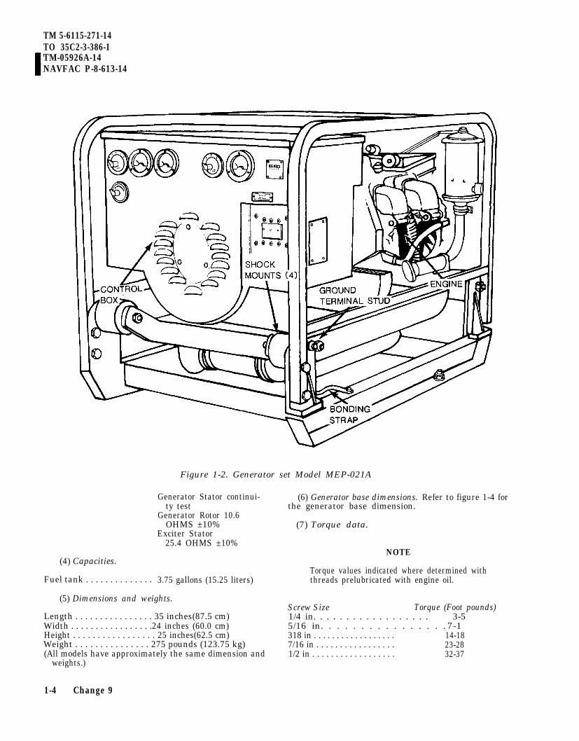
Figure 1-2. Generator set Model MEP-021A
Generator Stator continui-ty test
Generator Rotor 10.6OHMS ±10%
Exciter Stator25.4 OHMS ±10%
(6) Generator base dimensions. Refer to figure 1-4 forthe generator base dimension.
(7) Torque data.
(4) Capacities.
Fuel tank . . . . . . . . . . . . . . 3.75 gallons (15.25 liters)
(5) Dimensions and weights.
Length . . . . . . . . . . . . . . . . 35 inches(87.5 cm)Width . . . . . . . . . . . . . . . . .24 inches (60.0 cm)Height . . . . . . . . . . . . . . . . . 25 inches(62.5 cm)Weight . . . . . . . . . . . . . . . 275 pounds (123.75 kg)(All models have approximately the same dimension and
weights.)
1-4 Change 9
NOTE
Torque values indicated where determined withthreads prelubricated with engine oil.
Screw Size Torque (Foot pounds)1/4 in. . . . . . . . . . . . . . . . . . 3-55/16 in. . . . . . . . . . . . . . . . 7-1318 in . . . . . . . . . . . . . . . . . .7/16 in . . . . . . . . . . . . . . . . .1/2 in . . . . . . . . . . . . . . . . . .
14-1823-2832-37

TM 5-6115-271-14TO 35C2-3-386-1
TM-05926A-14NAVFAC P-8-613-14
F R A M E
Figure 1-3. Generator set Model MEP-026A
(8) Wiring diagrams. Refer to FO-1 throughFO-3, practical wiring diagram. (These diagrams arelocated in the back of the manual.) Refer to figures10-1 through 10-3 for schematic diagram.
(9) Maintenance and operating supplies. Referto Chapter 3 for a complete list of maintenance andoperating supplies required for initial operation.
1-11. Differences Between Models
This manual covers DOD Models MEP-016A,MEP-016C, MEP-021A, MEP-021C, and MEP-026A,MEP-026C. The differences that exist between thesemodels are thoroughly discussed in the appropriateportions of the manual. The basic difference betweenmodels is MEP-016A/C delivers 60 hertz (AC) current;the MEP-021A/C delivers 400 hertz (AC) current, andthe MEP-026A/C delivers direct current.
The difference between the “A” and “C” models isthat the “A” model is powered by a model 4A032-1 or4A032-2 engine, while the “C” model is powered by amodel 4A032-3 engine. The basic difference betweenthe 4A032-1/-2 and the 4A032-3 engine is that the4A032-1/-2 engine has a conventional ignition systemwhile the 4A032-3 engine has a breakerless ignitionsystem (BIS) and a larger rope cranking pulley. The4A032-3 engine is far easier to start and also hasgreater reliability and requires less maintenance. Notethat the “B” models are not covered by this manualsince they are DED generator sets.
DOD accepted Army Standard 3KW Models asDOD Standard, hence, SF-3.0-MD, 60 Hz, NSNs6115-00-075-1640 (Bogue), 6115-00-879-9734 (Holl-ingsworth) and 6115-00-913-9290 (Eagle) weredesignated as Model MEP-016A with single NSN6115-00-017-8237. Likewise, HF-3.0-MD, 400 Hz,NSNs 6115-00-012-1992 (Bogue) and6115-00-937-1794 (Eagle) were designated as Model
1 - 5

TM 5-6115-271-14TO 35C2-3-386-1TM 05926A-14NAVFAC P-8-613-14
MEP-021A assigned NSN 6115-00-017-8238 andModel DC-3.0-MD/28, 6115-00-012-1997 (Bogue)6115-00-879-9747 (Hollingsworth) 6115-00-916-9460(Eagle) designated as MEP-026A assigned NSN6115-00-017-8239.
Figure 1-4 Generator base dimensions
1-6

TM 5-6115-271-14TO 35C2-3-386-1
TM-05926A-14NAVFAC P-8-613-14
CHAPTER 2OPERATING INSTRUCTIONS
Section I. OPERATING PROCEDURES
2-1 Controls and Instruments
a. General. This paragraph provides informationabout the various controls and instruments forproper operation of the generator sets.
b. 400 Hz Generator Set. The purpose andnormal readings of all 400 Hz generator set controlsand instruments are illustrated in figures 2-1 and2-2.
c. 60 Hz Generator Set. The purpose andnormal readings of all 60 Hz generator set controlsand instruments are shown in figures 2-1 and 2-3.
d. 28 Volt DC Generator Set. The purpose andnormal readings of all 28 volt DC generator setcontrols and instruments are shown in figures 2-1and 2-4.
2-2.
a.
Operations Under Usual Conditions
General
(1) The instructions in this paragraph arepublished for the information and guidance ofpersonnel responsible for operation of thegenerator sets.
(2) The operator must know how to performevery operation of which the generator sets arecapable. This section gives instructions on startingand stopping the generator sets and regulatingthem to perform the specific task for which theequipment is designated.
WARNING
Operation of this equipment presents anoise hazard to personnel in the area.The noise level exceeds the allowablelimits for unprotected personnel. Wearear muffs or ear plugs which werefitted by a trained professional.
b. Starting.
(1) Preparation for starting.
(a) (A, F, N, MC) Perform the dailypreventive maintenance checks and services (Table3-2).
(b) Connect the auxiliary fuel hoseto the fuel selector valve (C, fig. 2-1), if an externalfuel source is to be used.
(c) Select the proper voltage to meetload requirements (fig. 2-5).
(d) Properly ground the generator set bydriving ground rod (see Items Troop Installed orAuthorized List, Section III, Page B-2) eight feetinto the ground. Connect the remaining end ofthe wire to the ground stud of the generator set.If the ground is of sufficient hardness to preventthe ground rod being driven into the ground atthe proper depth, a metal plate three or morefeet in diameter may be buried in the groundin lieu of the ground rod and if necessary dirtpiled up around and over it above ground level.The area around the plate should then be keptsaturated with water.
2-1

TM 5-6115-271-14TO 35C2-3-386-1TM-05926A-14NAVFAC P-8-613-14
(2) Electrical starting (optional equipment).
NOTEA starter kit is available for generalissue. Models MEP-016C, MEP-021C,and MEP-026C are easy to manuallystart, but may need the kit in veryfrigid climates, See Appendix B, SectionIII, for the kit and/or individual com-ponents, and requisitioning instructions.
(a) Connect a 24/28 volt external powersource to the receptacle,
(b) Refer to figure 2-6, sheets 1 and 2and start the engine electrically.
(3) Manual starting.
WARNING
Serious eye injury can result from thestarter rope knot. Wear eye protectionwhen pull starting engine.
(a) Refer to figure 2-6, sheet 1 of 2 andperform steps 1 through 7.
(b) Refer to figure 2-7 and start theengine manually.
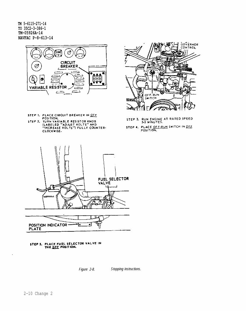
c. Stopping. Refer to figure 2-8 and stop theengine.
d. Operation of Equipment.
CAUTION
Do not operate at idle speed with orwithout load attached. At idle speed,frequency drops below 60 Hz, exciterfield voltage increases, thereby causingvoltage regulator to operate at maximumoutput. This causes overloading of powertransistor.
(1) General. When the engine is operatingand the load is connected, the generator operatesat its rated voltage. The generator set modelsMEP-016A/C and MEP-026A/C are designed tooperate continuously at 3600 revolutions per min-ute in accordance with the engine governor setting.MEP-021A/C operates at 3428 revolutions perminute. The operator must always be observant of the
2-2 Change 10

TM 5-6115-271-14TO 35C2-3-386-1
TM 05926A-14NAVFAC P-8-613-14
Figure 2–1. Engine Controls.
2-2.1/(2-2.2 blank)


TM 5-6115-271-14TO 35C2-3-386-1
Figure 2-2. Generator set controls and instruments (Model MEP-021A).
generator set, paying particular attention to unu-sual sounds which indicate malfunction. In suchan event, stop the engine and report the conditionto the appropriate maintenance personnel.
NOTEThe controls and instruments on later MEPmodels have a slightly different location on theface of the control box. However, these instruc-tions apply in the same manner.
(2) Operation.. - .
(a) Operate the 400 Hz and 60 Hz generator (b) Operate the 28 volt dc generator set assets as instructed in figure 2–9, sheets 1 and 2. instructed in figure 2–10.
2-3

Figure 2-3.
TM
5-6115-271-14TO
3
5C
2-3
-38
6-1
2-4

TM 5–6115-271-14TO 35C2–3–386-1
Figure 2-4. Generator set controls and instruments (Mode MEP-26A).
2 - 5

TM 5-6115-271-14TO 35C2–3-386-1
2 - 6
Figure 2-5. Voltage conversion (models MEP-016A and MEP-021A).

TM 5-6115-271-14TO 35C2-3-386-1
TM-05926A-14NAVFAC P-6-613-14
Figure 2-6. Typical electrical starting instruction (sheet 1 of 2).
2 - 7

TM 5-6115-271-14TO 35C2-3-386-l
TM-05926A-14NAVFAC P-8-613-14
Figure 2-6 Continued. Typical electrical starting instructions (sheet 2 of 2).
2-8

Step 1.
Step 2.
Step 3.
Step 4.
Step 5.
Step 6.
TM 5-6115-271-14TO 35C2-3-386-1
TM-05926A-14NAVFAC P-8-613-14
Set the circuit breaker to OFF or OPEN WARNINGposition. Serious eye injury can result from theSet the fuel selector valve to the TANK or starter rope knot. Wear eye protectionAUX position whichever fuel source you are when pull starting engine.using.Set the output selector switch it is inside the c. Make one pull of the starter rope withcontrol box to the generator (voltage) output a quick, steadv motion.that matches the connected load. d. If the engine starts, open choke asTurn the voltage adjusting rheostat all the steady engine operation permits.way to the left.Set the carburetor throttle control in CAUTIONGOVERN or RUN position. Unnecessary or excessive use of the choke
a. Set the engine RUN-OFF switch toRUN position.
can cause the lubricating oil to be dilutedwith gasoline.
b. Put the choke in about a 3/4-closedposition. e. If the engine does not start, close choke
to full. Take one pull of starter rope. If enginestarts, move choke to about 1/2-position. Runengine at 1/2-choke, then open choke assteady engine operation permits.
Figure 2-7. Manual starting instructions.
2-9
TM 5-6115-271-14TO 35C2-3-386-1TM-05926A-14NAVFAC P-8-613-14
Figure 2-8. Stopping instructions.
2-10 Change 2

1.
2.
3.
4.
TM 5-6115-271-14TO 35C2-3-386-1
TM-05926A-14NAVFAC P-8-613-14
PLACE CIRCUIT BREAKER IN THE OFFPOSITION AND TURN VARIABLERESISTOR KNOB COUNTER-CLOCKWISEUNTIL IT STOPS.PLACE OUTPUT SELECTOR SWITCH INDESIRED POSITION (FIG. 2-5).PLACE GOVERNOR CONTROL INGOVERN POSITION.START THE GENERATOR SET.
TS 011889
Figure 2-9. Generator set operating instructions (Models MEP-016A and MEP-021A) (Sheet 1 of 2).
Change 9 2-11

TM 5-6115-271-14TO 35C2-3-386-1TM-05926A-14NAVFAC P-8-613-14
STEP 5.
STEP 6.
STEP 7.
NOTE:
STEP 8.
STEP 9.
SET THE VOLTAGE SELECTOR SWITCH COMPATIBLE TO THE CONNECTIONS AT THE LOADTERMINALS, THE OUTPUT BETWEEN ANY TWO TERMINALS WILL BE INDICATED ON THEVOLTMETER. FOR EXAMPLE, IF THE VOLTAGE SELECTOR IS SET ON V 1-2 IT WILLCAUSE AN INDICATION ON THE VOLTMETER, REFLECTING THE VOLTAGE OUTPUTBETWEEN LOAD TERMINALS 1 AND 2.
USING THE VARIALE RESISTOR ADJUST UNTIL THE VOLTMETER REGISTERS DESIREDVOLTAGE. THE LOAD METER SOUL READ “O”.
INSPECT THE FREQUENCY METER. IT SHOULD INDICATE 400 HZ OR 60 HZ,DEPENDING ON WHICH MACHINE IS BEING OPERATED.
IF THE FREQUENCY READING IS INCORRECT, THE ENGINE GOVERNOR MUST BEADJUSTED. REFER TO APPENDIX A FOR GOVERNOR ADJUSTMENT,
PLACE THE CIRCUIT BREAKER IN THE ON POSITION TO APPLY THE LOAD.
USE THE CURRENT SELECTOR SWITCH AND THE LOAD METER INDICATIONS TODETERMINE THE CURRENT DRAW ON EACH TERMINAL (EXCLUDING TERMINAL “LO”)AND PHASE THE LOAD READING SHOULD NOT EXCEED 100% AT ANY POSITION OFTHE CURRENT SELECTOR SWITCH.
CAUTION: IF MORE THAN 100 PERCENT OF FULL LOAD CURRENT IS INDICATED ON THE LOADMETER, REDUCE THE LOAD OR STOP THE GENERATOR SET AND REPORT TOORGANIZATIONAL MAINTENANCE.
STEP 10.
NOTE:
STEP 11.
READJUST THE VARIABLE RESISTOR, IF NECESSARY, TO COMPENSATE FOR THECURRENT DRAW:
THE FIELD FLASH SWITCH IS TO BE USED AS A MANUAL METHOD OF FLASHING THEGENERATOR FIELDS ONLY WHEN THE VOLTAGE FAILS TO BUILD UP AUTOMATICALLYLATER MODELS HAVE NO FIELD FLASH SWITCH.
WHEN THE OPERATION IS COMPLETE, PLACE THE CIRCUIT BREAKER IN THE OFFPOSITION AND STOP THE GENERATOR SET.
Figure 2-9. Generator set operating instructions(Models MEP-016A and MEP-021A)(Sheet 2 of 2).
2-12

TM 5-6115-271-14TO 35C2-3-386-1
TM 05926A-14NAVFAC P-8-613-14
Figure 2-10. Generator set operating instructions (Model MEP-026A).
Change 4 2-13

TM 5-6115-271-14TO 35C2-3-386-1TM 05926A-14NAVFAC P-8-613-14
Minimum Droop (Minimum Frequency Regulation)
Model 3-KW, 60 Hz 3-KW, 400 Hz 3-KW, 28VDCMEP-016A MEP-021A MEP-026A
RPM 3600 3428 3600
Frequency 60 Hz 400 Hz —
STEP 1.STEP 2.STEP 3.
STEP 4.
STEP 5.
STEP 6.
Move the governor control knob to the GOVERN or RUN position.Start engine and allow engine to warmup at rated speed for 3 to 5 minutes.Apply load. Loosen locknut A and turn minimum speed stop screw to obtain engine speed/frequen-cy given in table above. Tighten locknut A.Disengage load. Loosen locknut B and turn governor spring adjustment nut counterclockwise untilengine begins to “Surge” or “Hunt”. Then turn nut clockwise just enough to stop surging.Apply load and recheck engine speed/frequency. If engine speed/frequency is incorrect, perform opera-tions in Steps 3 through 5 and readjust.Tighten locknut B.
Figure 2-10.1 Governor Adjustment using Frequency Meter (Sheet 1 of 2).
2-14 Change 9

TM 5-6115-271-14TO 35C2-3-386-1
TM-05926A-14NAVFAC P-8-613-14
Maximum Droop (Maximum Frequency Regulation)
Model 3-KW, 60 Hz 3-KW, 400 Hz 3-KW, 28VDCMEP-016A MEP-021A MEP-026A
RPMA
3600 3428 3600Frequency 60 Hz 400 Hz —
RPM 3708 3530 3708B Frequency 61.8 Hz 412 Hz —
STEP 1.STEP 2.STEP 3.
STEP 4.
STEP 5.STEP 6.
Move the governor control knob to the GOVERN or RUN position.Start engine and allow engine to warmup at rated speed for 3 to 5 minutes.Apply load. Loosen locknut A and turn minimum speed stop screw to obtain engine speed/frequen-cy given in lines A of above table. Tighten locknut A.Disengage load and check engine speed/frequency. If speed/frequency does not exceed values givenin table above, lines B, no further adjustment is necessary. If speed exceeds values of table above,lines B, perform steps 5 and 6.Loosen locknut B and turn governor spring adjustment nut clockwise 4 turns. Tighten locknut B.Perform steps 3 and 4. NOTE: If no-load speed is adjusted too close to load speed, instability or hunt-ing will occur. If instability occurs, adjust governor spring adjustment nut to obtain no-load speed/fre-quency indicated in Table 1, Column B. Then perform steps 3 and 4 to obtain stability.
Figure 2-10.1 Governor Adjustment using Frequency Meter (Sheet 2 of 2).
Change 9 2-14.1

TM 5-6115-271-14TO 35C2-3-386-1TM 05926A-14NAVFAC P-8-613-14
Section Il. OPERATION OF AUXILIARY EQUIPMENT
2-3. Heating Torch Description line, pump type torch. It is used to preheat theengine to a point where the moving parts will
The heating torch is a l-pint (.47 liters), gaso- operate freely.
2 - 1 4 . 2 Change 4
F i g u r e 2 - 1 1 . H e a t i n g t o r c h o p e r a t i o n .

TM 5-6115-271-14TO 35C2-3-386-1
TM-05926A-14NAVFAC P-8-613-14
2-4. Heating Torch Operation overheating any single spot thereon. Do
Operate the heating torch as shown by figure 2-11.not apply direct heat or flame to the nylonfuel tank, the fuel tank lines and fuel filter
CAUTION system.Move heating torch continuously whileheat is being applied. This will prevent NOTEdamage to the engine crankcase from The heating torch should be applied at the
apertures (four on each side) beneath bothsides of the engine.
Section iii. OPERATION UNDER UNUSUAL CONDITIONS
2-5. Operation in Extreme Cold (Below 0°F. (-18°C.))
NOTEAt temperatures of -25°F. (-32°C.) to -65ºF.(-59 ‘C.), it may be necessary to utilize awinterization kit (fig. 3-2).
a. Keep the fuel tank as full as possible at all timesto prevent condensation.
b. Drain and service the fuel filter more often thanunder normal conditions. (See Appendix A for ap-propriate manual.)
c. Lubricate the engine as instructed in ap-propriate manuals (see Appendix A) and LO5-2805-203-12. Air Force will use the lubrication sec-tion of applicable T.O. 35C2-3-1-426 WC Seriesworkcards.
d. Remove any ice or snow which may have ac-cumulated on the engine, generator, or wiring.
CAUTIONDo not bend or kink wiring as it becomesbrittle with extreme cold.
e. Place the air intake shutter (fig. 2-1) in theWINTER position (to the left) when the ambienttemperature is 32°F. (0°C.) or lower.
NOTEIt may be necessary to utilize a heatingtorch to start the engine. If this doesbecome necessary, refer to paragraph 2-4.
f. After starting the engine, allow sufficient timefor it to reach normal operating temperature beforeapplying the load.
g. Observe the shutter at the top of the winteriza-tion shroud; if it does not operate properly the enginewill not reach operating temperatures. (See AppendixA for appropriate manual.)
h. When the generator set is not in operation,cover it with the canvas cover.
2-6. Operation in Extreme Heat
a. Indoor Ventilation. If the generator set isoperated indoors, allow sufficient room around theunit for air circulation and ventilate the room.
b. Cooling. Inspect covers, roof, and shrouds fre-quently to make sure they are clean and properly in-stalled. Place air intake shutter in the SUMMER posi-tion (to the right) when the ambient temperature isabove 32°F (0ºC).
c. Generator. Inspect load meter frequently tomake sure the generator is not overloaded.
d. Lubrication. Lubricate as specified in LO5-2805-203-12. Air Force will use the lubrication sec-tion of applicable T.O. 35C2-3-1-426 WC Seriesworkcards.
2-7. Operation in Dusty or Sandy Areas
a. Protection. Shield the generator set from dust.Take advantage of natural barriers which offer protec-tion from dust and sand.
b. Air Cleaners. Service the air cleaner daily tokeep the carburetor free of dirt and sand. (See Appen-dix A for appropriate manuals.)
c. Lubrication. Clean all lubrication points beforeapplying lubricants. Clean area around oil filler capbefore inspecting and adding oil.
d. Fuel. Prevent sand from entering fuel while ser-vicing the fuel tank. Service fuel tank strainer priorto adding fuel.
2-8. Operation under Rainy or Humid Conditions
a. General. If the unit is outdoors and is notoperating, cover the unit with the canvas cover.Remove the cover during dry period.
Change 3 2-15

TM 5-6115-271-14TO 35C2-3-386-1T M - 0 5 9 2 6 A - 1 4
NAVFAC P-8-613-14
b. Fuel. Keep the fuel tank as full as possible toprevent condensation.
c. Electrical System. Humid conditions can causecorrosion and deterioration of electrical components.Keep electrical components and wiring clean and dry.
2-9. Operation in Salt Water Areas
a. General. Wipe the generator set with a cleancloth dampened with clean, fresh water at frequent in-tervals. Use care not to contaminate the fuel supplyor damage the electrical system with water.
b. Lubrication. Use care to keep salt water fromentering the engine when adding or changing oil.Lubricate more frequently than specified in LO5-2805-203-12. Lubricate the engine as prescribed inthe appropriate manuals (see Appendix A) and LO5-2805-203-12. Air Force will use the lubrication sec-tion of applicable T.O. 35C2-3-1-426 WC seriesworkcards.
c. Preservation. Paint all exposed nonpolished sur-faces. Coat exposed parts of polished steel or other fer-rous material with standard issue rustproofingmaterial if available or cover parts with one light coatof grease. Refer to Appendix A.
2-10. Operation at High Altitudes
The generator sets are rated at 3 kw up to 8,000 feetaltitude. To calculate specific generator set outputabove 8,000 feet, use the following formula:
7% X actual altitude - 8,000 X 3 kw1,000
0.07X5X3 kw = kw derating
3 kw– 1.05 kw = 1.95 kw derated power at 13,000 ft.
2-11. Operation Using NATO Slave Cable
CAUTION
Before you use any cable, make sure themaster battery switches and all electricalswitches in both the live and dead equip-ment are in the OFF position. If you at-tempt to install the cable into liveoperating equipment, arcing can occur.You can get burned and your cable will bedamaged.
The existing Army Slave Cable has end connectorswith two pins to mate with the Slave Receptacle onthe Generator Set (fig. 1-3). The NATO Slave Cablehas end connectors with one pin. In order to utilize theNATO Slave Cable on the Generator Set, an AdapterConnector must be used. See Additional Authoriza-tion List (AAL) for Adapter Connector.
2-16 Change 9

TM 5-6115-271-14TO 35C2-3-386-1
TM-05926A-14
CHAPTER 3NAVFAC P-8-613-14
OPERATOR/CREW MAINTENANCE INSTRUCTIONSSection i. CONSUMABLE OPERATING AND MAINTENANCE SUPPLIES
3-1. General
This section contains a table listing the consumablemaintenance and operating supplies required tooperate and maintain the generator set. This table in-cludes only items peculiar to and required formaintenance and operation.
3-2. Explanation of Columns
An explanation of columns in the tabular listfollows:
a. Component Application. This column identifiesthe component application of each maintenance oroperating supply item.
b. National Stock Number. This column indicatesthe National Stock Number assigned to the item andwill be used for requisitioning purposes.
c. Description. This column indicates the itemname and brief description.
d. Quantity Required for Initial Operation. Thiscolumn indicates the quantity of each maintenance oroperating supply item required for initial operation ofthe equipment.
e. Quantity Required for Eight Hours Operation.This column indicates the estimated quantities re-quired for an average 8 hours of operation.
f. Notes. This column indicates informative noteskeyed to data appearing in a preceding column.
Table 3-1. Maintenance and Operating Supplies
(1)
Componentapplication
CRANKCASE (1)
(2)
Nationalstock number
9150-00-265-9433(2)
9150-00-265-9425(2)
9150-00-242-7632(2)
9130-00-160-1818(2)
9130-00-160-1830(2)
9130-00-148-7103
Section ii.
(3)
Description
OIL, LUBRICATION:1 qt. can as follows:
OE30
OE10
OES
FUEL, GASOLINE, 5gal. pail as follows:
AUTOMOTIVE,COMBAT91A
AUTOMOTIVE,COMBAT,91C
GASOLINE, UNLEAD-ED regular gradeVV-G-001690
(4)Quantityrequiredf/initial
operation
2-1/8 qt(2 liters)
2-1/8 qt(2 liters)
2-1/8 qt(2 liters)
3¾ gal (4)(14.25 1.)
3¾ gal (4)(14.25 1.)
(5)Quantityrequired
8 hrs.operation
(3)
(3)
(3)
(5)
(5)
(6)
Notes
(1) Includes quantity ofoil to fill engine oilsystem as follows:
1-5/8 qt—crankcase1/2 qt–filter
(2) See FSC 9100-IL foradditional data and re-quisitioning procedure.
(3) See current LO forgrade application andreplenishment intervals.
(4) Tank capacity.
(5) Average fuel consump-tion is 0.95 gal. per hourof continuous operation.
LUBRICATING INSTRUCTIONSLubrication is not required for the generator. For 5-2805-203-12. Air Force will use the lubrication sec-
general lubrication information on the engine, Army, tion of applicable T.O. 35C2-3-1-426 WC SeriesMarine Corps, and Navy users should refer to LO workcards.
3-1

TM 5-6115-271-14TO 35C2-3-386-1TM-05926A-14NAVFAC P-8-613-14
Section III. PREVENTIVE MAINTENANCE CHECKS AND SERVICES (PMCS)
3-3. General
To insure that the generator is set and is ready foroperation at all times, it must be inspectedsystematically so that defects maybe discovered andcorrected before they result in serious damage orfailure. The necessary daily preventive maintenanceservices to be performed are listed and described inparagraph 3-4. Item numbers indicate the sequence ofminimum inspection requirements. Defectsdiscovered during operation of the unit shall be notedfor future correction, to be made as soon as operationhas ceased. Stop operation immediately if a deficien-cy is noticed which would damage the equipment ifoperation were continued.
3-4. Daily Preventive Maintenance Checks andServices
Table 3-2 contains a tabulated listing of preventivemaintenance checks and services for the generator setwhich shall be performed by the operator/crew person-nel. Refer to TM 5-2805-203-14 for engine preventivemaintenance, checks and services. The item numbersare listed consecutively and indicate the sequence ofminimum requirements.
3-2 Change 9

TM 5-6115-271-14TO 35C2-3-386-1
TM 05926A-14NAVFAC P-8-613-14
Table 3-2. OPERATOR/CREW PREVENTIVE MAINTENANCE CHECKS AND SERVICES
B-BEFORE OPERATION A-AFTER OPERATIONINTERVAL D-DURING OPERATION
PROCEDURES EQUIPMENT IS
ITEM B D A ITEM TO BE CHECK FOR AND HAVE REPAIRED NOT READYNO. INSPECTED OR ADJUSTED AS NECESSARY AVAILABLE IF:
1 ● Generator set a. Check generator set for Generator is nottight ground connections and gounded properly.proper ground rod installation.
2 Gages and Check for proper generator Class III oilInstruments operation. leakage or any fuel
leaks are detected.
Models MEP-016Aand
MEP-021A● a. Voltmeter Adjust for desired voltage. Voltage cannot be
Rotate voltage selector switch adjusted.to monitor the various outputvoltage combinations.
● b. Frequency Normal indication: Indicatesmeter MEP-021A; 400 Hz (392 to frequency too high
408) or too low.MEP-016A, 60 Hz (59 to
61)● c. Load meter Indicates percentage of applied
load. Rotate current selectorswitch to monitor the loadapplied to each phase. Not toexceed 100%.
Model MEP-026A● d. Voltmeter Adjust for proper DC volts Voltage cannot be
(must not exceed 28 V max). adjusted.
Change 10 3-2.1

TM 5-6115-271-14TO 35C2-3-386-1TM 05926A-14NAVFAC P-8-613-14
Table 3-2. OPERATOR/CREW PREVENTIVE MAINTENANCE CHECKS AND SERVICES
B-BEFORE OPERATION A-AFTER OPERATIONINTERVAL D-DURING OPERATION
Procedures Equipment IsItem B D A Item To Be Check For And Have Repaired Not Ready
No. Inspected Or Adjusted As Necessary Available If:
3 Fuel Tank
WARNINGWhen handling gasoline, alwaysprovide a metal-to-metal contactbetween the container and fueltank. This will prevent a sparkfrom being generated as gasolineflows over the metallic surface.
Never service generator set whenin operation.
After operation, assure that tankis full to prevent moisture con-densation.
After operation, fill tank to preventmoisture condensation.
4 Generator Set Check entire generator set for loose ormissing hardware and excessive orunusual wear or damage. Inspect forcracked or broken welds. Clean set.
NOTESee TM 5-2805-203-14 for enginepreventive maintenance checks andservices, and LO 5-2805-203-12.
3 - 2 . 2

Section IV. TROUBLESHOOTING
3-5. General
This section contains troubleshooting or mal-function information and tests for locating andcorrecting most of the troubles which may developin the generator sets. Each malfunction or troublesymptom for an individual component, unit, orsystem is followed by a list of tests or inspectionsnecessary for you to determine probable causesand suggested corrective actions for you to rem-edy the malfunction.
3-6. Troubleshooting
a. This manual cannot list all possible malfunc-tions that may occur or all tests or inspectionsand corrective actions. If a malfunction is notlisted (except when malfunction and cause areobvious), or is not corrected by listed correctiveactions, you should notify higher level mainte-nance.
b. Table 3-3 lists the common malfunctions that
TM 5-6115-271-14TO 35C2-3-386-1
TM 05926A-14NAVFAC P-8-613-14
you may find during the operation or mainte-nance of the generator sets or their components.You should perform the tests/inspections and cor-rective actions in the order listed.
NOTEBefore you use this table, be sure you have per-formed all normal operational checks. If you havea malfunction which is not listed in this table,notify the next higher level of maintenance.Air Force users may perform maintenance withinthe scope of their capabilities.
Table 3-3. Troubleshooting
MALFUNCTIONTEST OR INSPECTION
CORRECTIVE ACTION
1. GENERATOR FAILS TO BUILD UP TORATED VOLTAGE (All Models)Check to see if the variable resistor is correctly ad-justed. The voltmeter reading will change as the vari-able resistor knob is turned.
Change 3 3-2.3 /(3-2.4 blank)


Table 3-3. Troubleshooting (Cont’d)
MALFUNCTIONTEST OR INSPECTION
CORRECTIVE ACTION
1. GENERATOR FAILS TO BUILD UP TORATED VOLTAGE (All Models) (Cont’d)
Place the circuit breaker in the OFF position.Turn the variable resistor knob (labeled “ad-just volts” and “increase volts”) until therequired voltage is attained.
2. GENERATOR OVERHEATS (All Models)Visually inspect for material trapped over the genera-tor ventilators.
Remove any restrictions that were blockingthe ventilators.
3. GENERATOR FAILS TO SUPPLY LOAD(Model MEP-016A)Step 1. Check for a defective fuse by removing the
two fusecaps. Push in and turn the capscounterclockwise, and pull the fuses out. In-spect the fuses for burns, cracks, or breaks.Replace the fuse with another fuse carrying a15-amp, 250 volt rating. To install, push inand turn the cap clockwise.
Step 2. Check for a cracked, broken or corroded fuse-holder.
TM 5-6115-271-14TO 35C2-3-386-1TM 05926A-14
NAVFAC P-8-613-14Table 3-3. Troubleshooting (Cont’d)
MALFUNCTIONTEST OR INSPECTION
CORRECTIVE ACTION
3. GENERATOR FAILS TO SUPPLY LOAD(Model MEP-016A) (Cont’d)
Step 3.
Step 4.
Step 5.
Refer to organizational maintenance person-nel.Inspect the load terminals for cracks, breaks,loose terminals and other damage.Refer to organizational maintenance person-nel.Check the circuit breaker to see if it is open.Close the circuit breaker.If the circuit breaker will not stay closed, it isdefective.Refer to organizational maintenance.
4. GENERATOR VOLTAGE FLUCTUATESInspect for audible engine speed fluctuation.
Refer to APPENDIX A.
5. UNIT CAUSES RADIO INTERFERENCEStep 1. Inspect the load lines for loose connections.
Tighten all load line connections securely.Step 2. Inspect established ground for loose connec-
tions.Tighten all ground connections securely.
Section V. MAINTENANCE PROCEDURES
3-7. General
This section contains information on the main-tenance of the equipment that is the responsibil-ity of the operator.
WARNING
Before servicing any part of the genera-tor set, make certain that the engine isstopped. Failure to observe this safetyprecaution could result in severe elec-trical shock or death by electrocution.
3-8. Frame, Shock Mounts and Ground Stud
Inspect the frame, shock mounts, and groundstud (fig. 1-2) for any signs of damage or wear.Refer all removal and/or installation to organiza-tional maintenance personnel.
3-9. Controls and Instruments
Clean all meters (figs. 2-2, 2-3 and 2-4) andinspect them for broken glass, improper operationor other damage. Inspect controls for ease ofoperation, broken knobs, or other obvious damage.Refer any control or instrument requiring re-
placement to organizational maintenance person-nel.
3-10. Fuse and Fuseholder (Model MEP-016A)
a. Inspection. Inspect fuse to determine if it isdefective. Inspect fuseholder for possible damage.
b. Removal and Installation. Refer to figure 3-1to remove a defective fuse and install a new one.Refer removal or installation of the fuseholder toorganizational maintenance personnel.
3-11. Fuel Tank, Fuel line, Fuel Hose, andFuel Selector Valve
Inspect the fuel tank (B, fig. 4-12), fuel line (fig.4-19), fuel hose (fig. 4-19), and fuel selector valve(fig. 4-19) for any signs of damage or wear. Referto all removal and/or installation to organizationalmaintenance personnel.
3-12. Fuel Filter and Air Cleaner
Service for the fuel filter (fig. 4-19) and aircleaner is as shown in service manuals. (See Ap-pendix A.)
Change 3 3 - 3

TM 5-6115-271-14TO 35C2-3-386-1TM 05926A-14NAVFAC P-8-613-14
Figure 3-1. Fuse, removal and installation (Model MEP-016A).
3-13. Fuel Tank Strainer
a. Cleaning and Inspection. Inspect fuel tankstrainer (A, fig. 4-12) for damage of any kind.Clean strainer as necessary. Replace a damagedstrainer.
b. Removal and Installation. Remove fuel tank
3-4 Change 7
cap from filler neck (A, fig. 4-12) and remove thefuel tank strainer by lifting it from the filler neck.
3-14. Fuel Tank Cap and Chain Assembly
a. Inspect. Inspect the fuel tank cap and chainassembly (A, fig. 4-12) for cracks, breaks, loosefitting, and other obvious damage.
b. Removal and Installation. Refer to A, figure4-12 to remove and install the fuel tank cap andchain assembly.
3-15. Muffler Brackets, Muffler and MufflerPipes
Inspect the muffler brackets, muffler and muf-fler pipes (fig. 4-20) for any damage. Refer allremoval and/or installation to organizationalmaintenance personnel.
3-16. Generator
Clean the generator and inspect it for cracks,breaks, loose mountings, and other obvious dam-age. If the generator is damaged, refer to organi-zational maintenance personnel.
3-17. Winterization Kit (Fig. 3-2)
a. The winterization kit is of a waterproof nylonmaterial with a flame retarding coating. The ma-terial is flexible for easing storing when not inuse. The kit is to permit operation of the unit attemperatures of –25° F. (-32° C.) to –65° F.(–54° C). When in use, the kit completely coversthe operating unit except for air intake and ex-haust outlet ports.
b. Inspect the kit (fig. 3-2) for rips, tears, orother damage. Replace a damaged kit.

FIG
UR
E 3-2.
3-5
TM
5-6115-271-14T
O 35C
2-3–386-1


TM 5-6115-271-14TO 35C2-3-386-1
TM 05926A-14NAVFAC P-8-613-14
C H A P T E R 4
ORGANIZATIONAL MAINTENANCE
Section I. SERVICE UPON RECEIPT OF EQUIPMENT
4-1. Inspection and Servicing the Equipment
a. Depreservation. Prepare the generator set forinspection and operation as outlined on the de-tailed Depreservation Guide for Vehicles andEquipment (DA Form 2258) which is attached tothe generator when received new or from rebuild.
b. Inspection.(1) (A, F) perform the Daily Preventive Main-
tenance Services (Table 3-2).(2) Refer to Appendix A for engine manuals
and inspect and service the engine.(3) Make a thorough visual inspection of the
entire generator set for damage and missing partsand accessories. Report all damaged or missingparts on DD Form 6.
c. Servicing. (1) For lubrication of the engine, Army, Navy
and Marine Corps users should refer to ap-propriate service manuals and LO 5-2805-203-12.Air Force will use the lubrication section of ap-plicable T.O. 35C2-3-1-426 WC Series workcards.The generator is equipped with sealed bearingsand does not require lubrication.
WARNING
When handling gasoline, always providea metal-to-metal contact between thecontainer and fuel tank. This will pre-vent a spark from being generated asgasoline flows over the metallic sur-faces. When gas tank filler neck is onthe same side, or adjacent to load termi-nals, never service when set is operat-ing.(2) Service the fuel filter (see Appendix A).
Remove the fuel tank cap and fill the fuel tankwith the proper grade of fuel. Fuel strainer shouldbe removed from fuel tank filler neck and cleanedthoroughly. If fuel strainer is damaged in anyway, it should be replaced. Inspect filler cap,chain, and gasket for damage. Replace a damagedcap assembly.
4-2. Installation.
WARNING
Do not operate the generator set in aninclosed area unless the exhaust gasesare piped to the outside. Inhalation ofthe exhaust fumes can result in seriousillness or death.
a. General. If the generator set is attached to ashipping platform, this will provide an adequatefoundation. Otherwise, use planks, timbers, am-munition boxes, or other available material toprevent the skids from sinking into soft ground orsand. The level of the set should not exceed a tiltof 15 degrees in any direction. Drainage must beprovided to insure run-off of water from the gen-erator set. Refer to figure 1-4 for dimensions ofthe base.
b. Grounding Procedure.
WARNING
Do not rely on grounding or safetydevices to prevent accidents. Electricalcircuits and equipment are potentiallyhazardous. Personnel should always ex-ercise caution to prevent injury or pos-sible death due to electrical shock.Generator sets shall be grounded inorder to prevent shock due to defectiveinsulation, or external electrical faults.Poor grounding can endanger person-nel, may damage equipment, and cancreate interference in communication orelectronic circuits.
(1) Install one of the following items as agrounding device:
(a) Drive a ground rod to a depth of at least8 feet.
(b) Drive a ground pipe, 3/4 inch copper orsteel, to a depth of at least 8 feet. An existingunderground pipe may be used in an emergency.
Change 3 4-1

TM 5-6115-271-14TO 35C2-3-386-1
(c) Bury a ¼ inch thick iron or steel plate,approximately 18 inch x 18 inch size, with groundcable attached, to a depth of at least 4 feet.
(d) Bury a 1/16 inch thick aluminum orcopper plate approximately 18 inch x 18 inch size,with ground cable attached, to a depth of at least4 feet.
(e) Position a ¼ inch thick iron or steelplate, or 1/16 inch thick aluminum or copperplates, approximately 18 inch x 18 inch size, onthe hard ground or bedrock beneath the trailerstand or roll the wheel of a trailer or truck until itcomes to rest on top of the grounding plate.
(f) Saturate the area around the groundingdevice with water to increase conductivity.
(2) Ground cables should be copper. Braidedcable is the best, but No. 6 AWG gauge (or larger)copper wire will suffice.
(3) Connect the ground cable from the ground-ing device to the generator set frame ground stud(fig. 1-2) and tighten the nut securely.
c. Connecting Load Cables.(1.) AC generators. Refer to figure 4–1 and
connect the load cables to the AC generator loadterminals.
Figure 4-1. AC Generator set load terminals.
4-2

(2) DC generator. Refer to figure 4-2 and con-nect the load cables to the DC generator load termi-nals. Relatively light electrical loads (12 amps) maybeconnected to the generator set by plugging in to theslave receptacle (fig. 1-3).
d. External Fuel Source. If an auxiliary fuel sourceis to be used, connect the auxiliary fuel hose to the fuelselector valve (C, fig. 2-1). A special adapter may berequired for all models (see Appendix B, Section III).
e. External Power Source. When an auxiliarypower source is to be used to start the engine, connectthe external power line to the receptacle illustrated infigure 4-3.
NOTEThe external power source must be 24/28volt direct current.
f. Indoor Installation. Keep the area well venti-lated at all times so the generator set will receive amaximum supply of air. Install a gas-tight exhaustline, as large as the exhaust outlet, to pipe the exhaust
Figure 4-2. DC generator set load terminals.
TM 5-6115-271-14TO 35C2-3-386-1
TM-05926A-14NAVFAC P-8-613-14
gases outdoors. Provide metal shields for the exhaustline if it passes through flammable walls. Wrap the linewith fiberglass if there is any danger of anyone touch-ing the exhaust line.
4-3. Equipment Conversion (Models MEP-016A,MEP-016C, and MEP-021A, MEP- 021C)
a. Refer to figure 2-5 for MEP-016A/C and MEP-021A/C for voltage and phase desired.
b. Refer to paragraph 4-2c and connect the loadcables to the proper load terminals.
4-4. Procedures for Constructing Revetment
a. General. This equipment is designed to operatein the open with unrestricted ventilation. In some situ-ations, it may be necessary to operate the equipmentfrom the protection of a revetment. This paragraphprovides information for the construction of a revet-ment to protect the equipment should it become nec-essary.
b. Dimensions. The minimum allowable insidedimensions are shown in figures 4-4 and 4-5. Theentrance to the revetment is shown in figure 4-6. Theseminimum dimensions are based solely on consider-ation of engine cooling and ventilation allowing
Figure 4-3. External power source receptacle.
4 -3

TM 5-6115-271-14TO 35C2-3-386-1TM-05926A-14NAVFAC P-8-613-14
a minimum practical amount of space for service andmaintenance.
c. Foundation and Drainage. Refer to figure 1-4 fordimensions of the generator base. In no case shouldthe foundation exceed a height of six inches norshould the level of the generator set exceed a tilt of 15°in any direction. Drainage must be provided to insurerun-off of water away from the generator set and outof the revetment through drain holes at inside groundlevel. Where there is no natural slope for the water torun away from the revetment, a sump and drainagetrench must be provided outside of the revetment foreach required drain hole.
d. Wall Construction. The walls of the revetmentmay be constructed with sandbags, ammunitionboxes filled with sand or dirt, or any other materialavailable. The wall height should not exceed 3 feet(0.91 meters) and should be constructed as shown infigures 4-6 and 4-7.
e. Roof Construction. The roof can be supportedby any means possible, but should be 1 foot (0.31meters) above the wall of the revetment and provideas much open space around the top as possible. Referto figures 4-5, 4-6, 4-7, 4-8 and 4-9. The materials us-ed in the roof construction consist of two pieces oflumber (4 inches by 4 inches) or logs (4 inches indiameter) about 10 feet (3.1 meters) long and thenecessary cross pieces of lumber, logs, or steel plank-ing to cover the entire roof as shown in figure 4-9.These cross pieces should be about 8 feet (2.44 meters)long. If the above materials are not readily available,any available material of a like nature maybe used.The thickness of the roof (figs. 4-6, and 4-8) will dependupon the amount and type of protection desired. Cau-tion should be taken when adding protection to theroof to insure that the roof is supported properly tocarry the additional weight.
f. Miscellaneous Construction. A compartmentshould be constructed for fuel storage outside of therevetment as shown in figure 4-4. The size of the fuel
storage area will depend upon the size of the fuel con-tainer being used. Since air temperatures within therevetment will build up considerably above the out-side ambient when the generator set is operating,always locate the fuel supply outside of the revetmentto minimize safety hazards associated with gasolineat high temperatures. For the same reason, it is recom-mended that the integral fuel tanks, with which somegenerator sets are equipped, not be used (see Appen-dix B, Section III). The exhaust from the generatorset is to be ducted out of the revetment. The installa-tion should be similar to that shown in figure 4-10. Ifflexible pipe is not available to use for an exhaust ex-tension, a piece of exhaust pipe or any other similarmaterial may be utilized. The point at which the ex-haust discharge goes through the revetment walldepends entirely upon the equipment that is available.The exhaust may be discharged into an external ex-haust chimney constructed as shown in figure 4-4.This chimney will aid in ducting the exhaust gasesaway from the revetment and will reduce the noiselevel. A revetment doorway shield must be con-structed as shown in figures 4-4, 4-5, and 4-9. Thisshield is a wall 3 feet (0.91 meters) high and 7.5 feet(2.26 meters) long, constructed in a manner similar tothe revetment walls to prevent direct entrance of pro-jectiles or fragments through the doorway into therevetment.
g. Alignment Instructions. When constructing therevetment, the orientation of the revetment will besuch that its entrance is facing into the direction of theprevailing wind (fig. 4-4). Each generator set will belocated within the revetment so that its long axis isparallel to the long axis of the revetment and iscentered within the revetment. In addition, the engineend will be towards the doorway. These instructionsare very important and must be observed to obtainmaximum ventilation and cooling benefits whenoperating in a revetment.
h. Multiple Installations. No more than onegenerator set will be installed within each revetment.Also, no other neat generating equipment will be plac-ed in the revetment with a generator set.
4-4 Change 9

TM 5-6115-271-14TO 35C2-3-386-1
Figure 4-4. Revetment, top view.
4-5

Figure 4-5.
TM
5-6115-271-14T
O 35C
2-3-386-1
4-6

Figure 4-6.
TM
5-6115-271-14T
O 35C
2-3–386-1
4-7

Figure 4-7.
TM 5-6115-271-14
TO 35C
2–3–386-1
4-8

FIG
UR
E 4-8
TM
5-6115-271-14T
O 35C
23-386-14–9

Figure 4-9.
TM
5-6115-271-14T
O 35C
2–3-386-1
4-10

Figure 4-10
TM
5-6115-271-14T
O 35C
2-3-386-1T
M 05926A
-14N
AV
FAC
P-8-613-14
4-11

TM 5-6115-271-14TO 35C2-3-386-1TM-05926A-14NAVFAC P-8-613-14
Section II. MOVEMENT TO A NEW WORKSITE
4-5. Dismantling for Movement b. Load and Ground Cables. Refer to paragraph4-2c and disconnect load and ground cables.
a. General. The generator set, being self-containedand lightweight, is readily portable. Disconnect any c. Fuel System. Remove the auxiliary fuel line, ifexhaust piping which may have been installed and used, and drain the fuel line. Drain the fuel filter bowl.remove all holddown bolts. Lift it at the four uppercorners of the frame. If it is to be transported, block 4-6. Reinstallation After Movementor tie it to the carrier to prevent damage by shiftingduring transit. Reinstall the generator set in the same manner as
described in paragraph 4-2.
Section III. REPAIR PARTS, SPECIAL TOOLS, SPECIAL TEST, MEASUREMENTAND DIAGNOSTIC EQUIPMENT (TMDE), AND SPECIAL SUPPORT EQUIPMENT
4-7. Tools and Equipment 4-8. Maintenance Repair Parts (A)
No special tools or equipment are required to per- Organizational maintenance repair parts are listedform organizational maintenance on the generator set. and illustrated in the publications listed in Appen-
dix A.
Section IV. PREVENTIVE MAINTENANCE CHECKS AND SERVICES (PMCS)
4-9. General
To insure that the generator set is ready for opera-tion at all times, it must be inspected systematicallyso that defects may be discovered and correctedbefore they result in serious damage or failure. Defi-ciencies discovered during operation of the unit shallbe noted for future correction, to be made as soon asoperation has ceased. Stop operation immediately ifa deficiency is noted during operation which woulddamage the equipment. All deficiencies and shortcom-ings shall be recorded together with the corrective ac-tion on the applicable format the earliest possible op-portunity. Army and Navy users shall accomplish thenecessary preventive maintenance services listed and
described in paragraph 4-10. Air Force users shallrefer to the applicable inspection manuals and workcard sets in the T.O. 35C2-3-1-426 Series for periodicrequirements and Table 4-1 for detailed procedures.
4-10 Preventive Maintenance Checks and Services(A, F)
The preventive maintenance checks and services tobe performed are in Table 4-1 for the generator set lessengine. Refer to TM 5-2805-203-14 for engine preven-tive maintenance checks and services. The itemnumbers are listed consecutively and indicate the se-quence of minimum requirements.
4-12 Change 9

SEE TM 5-2805-203-14TM 5-2805-203-14
TM 5-6115-271-14TO 35C2-3-386-1
TM 05926A-14NAVFAC P-8-613-14
Table 4-1. ORGANIZATIONAL PREVENTIVE MAINTENANCE CHECKS AND SERVICES
Section V. TROUBLESHOOTING4-11. General
This section contains troubleshooting or malfunctioninformation and tests for locating and correcting mostof the troubles which may develop in the generatorsets. Each malfunction or trouble symptom for anindividual component, unit, or system is followed by alist of tests or inspections necessary for you todetermine probable causes and suggested correctiveactions for you to remedy the malfunction.4-12. Troubleshooting
a. This manual cannot list all possible malfunctionsthat may occur or all tests or inspections, andcorrective actions. If a malfunction is not listed (exceptwhen malfunction and cause are obvious), or is notcorrected by listed corrective actions, you shouldnotify higher level maintenance.
b. Table 4-2 lists the common malfunctions that youmay find during the operation or maintenance of thegenerator sets or their components. You shouldperform the tests/inspections and corrective actions inthe order listed.
NOTEBefore you use this table, be sure you haveperformed all normal operational checks. If youhave a malfunction which is not listed in thistable, notify the next higher level ofmaintenance.
Air Force users may perform maintenancewithin the scope of their capabilities.
Table 4-2. Troubleshooting
MALFUNCTIONTEST OR INSPECTION
CORRECTIVE ACTION
1. GENERATOR FAILS TO SUPPLY LOAD
Step 1.
Step 2.
Step 3.
Inspect the load terminals for cracks, breaks,loose terminals and other damage. Replacethe load terminals (para 4-25). Check slavereceptacle on MEP-026A28VDC model;Repair or replace as necessary.
Check the circuit breaker to see if it is open.Close the circuit breaker; if the circuitbreaker will not stay closed, it is defective.Refer to intermediate (field), (Directsupport and general support) maintenancepersonnel.
Inspect the generator stator or rotor coils forloose connections or breaks. If either of theseparts are defective, there will be no voltageregistering on the voltmeter. Refer tointermediate (field), (Direct support andgeneral support) maintenance personnel.
2. GENERATOR FAILS TO SUPPLY LOAD(Model MEP-016A)
Step 1. Inspect for a cracked, broken or corrodedfuseholder.Replace the fuseholder (para 4-19).
Step 2. Test for a defective connector by plugging aknown good test lamp into the receptacle. Ifthe test lamp fails to illuminate connector isdefective.Replace the connector (para 4-23).
Change 12 4-13
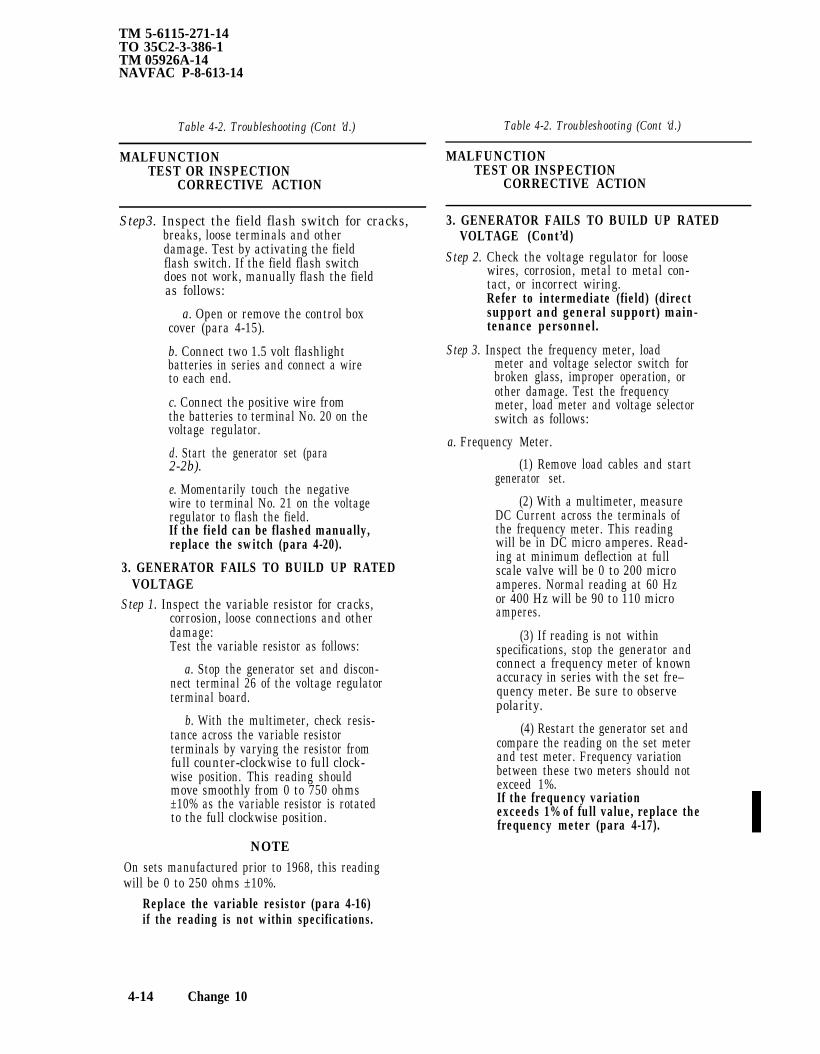
TM 5-6115-271-14TO 35C2-3-386-1TM 05926A-14NAVFAC P-8-613-14
Table 4-2. Troubleshooting (Cont ’d.)
MALFUNCTIONTEST OR INSPECTION
CORRECTIVE ACTION
Step3. Inspect the field flash switch for cracks,breaks, loose terminals and otherdamage. Test by activating the fieldflash switch. If the field flash switchdoes not work, manually flash the fieldas follows:
a. Open or remove the control boxcover (para 4-15).
b. Connect two 1.5 volt flashlightbatteries in series and connect a wireto each end.
c. Connect the positive wire fromthe batteries to terminal No. 20 on thevoltage regulator.
d. Start the generator set (para2-2b).
e. Momentarily touch the negativewire to terminal No. 21 on the voltageregulator to flash the field.If the field can be flashed manually,replace the switch (para 4-20).
3. GENERATOR FAILS TO BUILD UP RATEDVOLTAGE
Step 1. Inspect the variable resistor for cracks,corrosion, loose connections and otherdamage:Test the variable resistor as follows:
a. Stop the generator set and discon-nect terminal 26 of the voltage regulatorterminal board.
b. With the multimeter, check resis-tance across the variable resistorterminals by varying the resistor fromfull counter-clockwise to full clock-wise position. This reading shouldmove smoothly from 0 to 750 ohms±10% as the variable resistor is rotatedto the full clockwise position.
NOTEOn sets manufactured prior to 1968, this readingwill be 0 to 250 ohms ±10%.
Replace the variable resistor (para 4-16)if the reading is not within specifications.
Table 4-2. Troubleshooting (Cont ‘d.)
MALFUNCTIONTEST OR INSPECTION
CORRECTIVE ACTION
3. GENERATOR FAILS TO BUILD UP RATEDVOLTAGE (Cont’d)
Step 2. Check the voltage regulator for loosewires, corrosion, metal to metal con-tact, or incorrect wiring.Refer to intermediate (field) (directsupport and general support) main-tenance personnel.
Step 3. Inspect the frequency meter, loadmeter and voltage selector switch forbroken glass, improper operation, orother damage. Test the frequencymeter, load meter and voltage selectorswitch as follows:
a. Frequency Meter.
(1) Remove load cables and startgenerator set.
(2) With a multimeter, measureDC Current across the terminals ofthe frequency meter. This readingwill be in DC micro amperes. Read-ing at minimum deflection at fullscale valve will be 0 to 200 microamperes. Normal reading at 60 Hzor 400 Hz will be 90 to 110 microamperes.
(3) If reading is not withinspecifications, stop the generator andconnect a frequency meter of knownaccuracy in series with the set fre–quency meter. Be sure to observepolarity.
(4) Restart the generator set andcompare the reading on the set meterand test meter. Frequency variationbetween these two meters should notexceed 1%.If the frequency variationexceeds 1% of full value, replace thefrequency meter (para 4-17).
4-14 Change 10

Table 4-2. Troubleshooting (Cont’d.)
MALFUNCTIONTEST OR INSPECTION
CORRECTIVE ACTION
3. GENERATOR FAILS TO BUILD UP RATEDVOLTAGE (Cent’d)
b. Load Meter(1) Connect a load of known wat-
tage and proper voltage to the outputterminals of the generator set. Max-imum load is 3000 volts.
(2) Start the generator and put cir-cuit breaker in the ON position.Observe reading on set load meter.Meters should indicate according toload attached, i.e., 750-watts-25%,1500 watts–50%, etc.If load meter does not readwithin specifications, replace theload meter (para 4-17).
c. Voltage Selector Switch.(1) Disconnect load cables, start
generator set and allow it to warmup.
(2) Put circuit breaker in the ONposition. Check reading on voltageselector switch and voltmeter. With amultimeter, measure output voltageacross load terminals that are com-patible to the setting on the voltageselector swich.If proper voltages cannot beread on output terminals, replace thevoltage selector switch (para 4-21).
Step 4. Inspect the voltmeter, time meter andcurrent selector switch for broken glass,improper operation, or other damage.Test the voltmeter, time meter andcurrent selector switch as follows:
a. Voltmeter.(1) Remove load cables from load
terminals and start the generator set.
TM 5-6115-271-14TO 35C2-3-386-1TM-05926A-14
NAVFAC P-8-613-14
Table 4-2. Troubleshooting (Cont’d.)
MALFUNCTIONTEST OR INSPECTION
CORRECTIVE ACTION
3. GENERATOR FAILS TO BUILD UP RATEDVOLTAGE (Cont’d)
(2) Position circuit breaker switchto ON position.
(3) With a multimeter, measureoutput voltage across load terminals onall position settings of the voltageselector switch. Output voltage shouldnot vary more than 5% from the setvoltmeter.If the voltage on the voltmeter variesmore than 5%, replace the voltmeter(para 4-17).
b. Time Meter. Test the time total-izing meter by checking it against areliable clock. Check mission dura-tion time against the time totalizingmeter.Replace a defective, inoperative timetotalizing meter (para 4-18).
e. Current Selector Switch.(1) Stop the generator set.(2) Disconnect the input lead at
terminal 11. With a multimeter, checkcontinuity between terminals 11 and12 (I1), 11 and 13 (I2), 11 and 14(I3), on all three positions of thecurrent selector switch.If an open circuit is indicated onselected switch settings of the currentselector switch, the switch is defectiveand should be replaced (para 4-21).
4. GENERATOR NOISYInspect for loose, vibratingTighten the mounting bolts.
mounting bolts.
Change 10 4-14.1/(4-14.2 blank)


TM 5-6115-271-14TO 35C2-3-386-1TM-05926A-14
NAVFAC P-8-613-14
Section VI. RADIO INTERFERENCE SUPPRESSION
4-13. RFI Suppression Capacitors
a. General Methods Used to Attain ProperSuppression. Essentially, suppression is attained byproviding a low-resistance path to ground for straycurrents. The methods used include shielding theignition and high frequency wires, grounding theframe with bonding straps, and using capacitorsand resistors. For general information on radiointerference suppression, see Appendix A for theappropriate service manual.
b. Interference Suppression Components.
(1) Refer to figure 4-11 for location, des-cription, and removal and installation of suppres-sion components.
(2) For the removal and installation of theshielded spark plugs, refer to the appropriateservice manual in Appendix A.
CAUTIONDo not pull on cable or twist the braidedshielding. Gently work the cable fromside to side and free the rubber seal. Donot use sharp tools to install the rubberseal.
c. Replacement of Suppression Components.
(1) General. Replace radio interferencesuppression components with components of thesame size, type, and rating. The capacity, voltage,and polarity of the capacitors are extremelyimportant. Insure good metal-to-metal contactby using internal-external lockwashers.
(2) Removal and installation. Refer to figure4-11 and remove and install the capacitors andbonding straps.
d. Testing of Radio Interference SuppressionComponents.
NOTEThe only way to accurately test acapacitor is with a capacitor tester. How-ever, you can tell if a capacitor is work-ing by the following method.(1) Stop the generator set and disconnect
the lead in terminal to the capacitor.(2) With a multimeter on the ohms setting,
touch the test probes to the input terminal and themetal case of the capacitor, then quickly reversethe probes. The multimeter will give a momentaryreading then fall back to 0.
(3) If no deflection can be obtained on themultimeter scale, replace the capacitor (fig. 4-11).
Change 10 4-15

TM 5-6115-271-14TO 35C2-3-386-1TM-05926A-14NAVFAC P-8-613-14
Figure 4-11. Radio interference suppression components, location, description, removal and installation.
Section VII. MAINTENANCE OF THE FRAME ASSEMBLY
To remove and install the ground terminal stud, see figure 4-12. Refer any damage to the frame to direct support maintenance. Replace lost or broken terminal clip (retainer, safety clip). For fabrication procedures, seeparagraph 4-25A.
4-16 Change 9

TM 5-6115-271-14TO 35C2-3-386-1
TM 05926A-14NAVFAC P-8-613-14
Figure 4-12. Fuel tank and cap, and ground terminal stud removal and installation.
Section VIII. MAINTENANCE OF THE GENERATOR CONTROL BOX ASSEMBLY
4-14. GeneralThe generator control box assembly consists of the
meters, slave receptacle (Model ME P-016A/C only),circuit breaker, fuseholder (Model ME P-016A/C only).Field flash switch, voltage selector and current selec-
tor switch (Models MEP-016A/C and MEP-021A/C).Variable resistor (Labeled ADJUST VOLTS or in-crease volts), load terminals and buss bars (ModelMEP-026A/C).
4-15. Control Box Cover
a. General. Some models of the generator set areequipped with a fully removable control box cover (4quick fasteners), while other models are equipped witha hinged non-removable (2 quick fasteners) controlbox cover.
b. Opening, Removal and Installation. To open,remove or install the control box cover, simply loosen(or tighten) the two or four quick fasteners.
4-16. Variable Resistor
a. General. The variable resistors on eachgenerator set application differ slightly, but basicallyperform the same function. They can be recognized bythe circular identification plate under each controlknob which reads either INCREASE VOLTS ORADJUST VOLTS.
b. Test.
(1) Stop the generator set and disconnect ter-minal 26 of the voltage regulator terminal board.
(2) With a multimeter, check resistance acrossthe variable resistor terminals by varying the resistorfrom full counterclockwise to full clockwise position.This reading should move smoothly from 0 to 750ohms ±10% as the variable resistor is rotated to thefull clockwise position.
NOTEOn sets manufactured prior to 1968, thisreading will be 0 to 250 ohms ±10%.
Change 9 4-17

Figure 4-13.
TM 5-6115-271-14
TO 35C2-3-386-1
TM-05926A-14
NAVFAC
P-8-613-14
4–
18
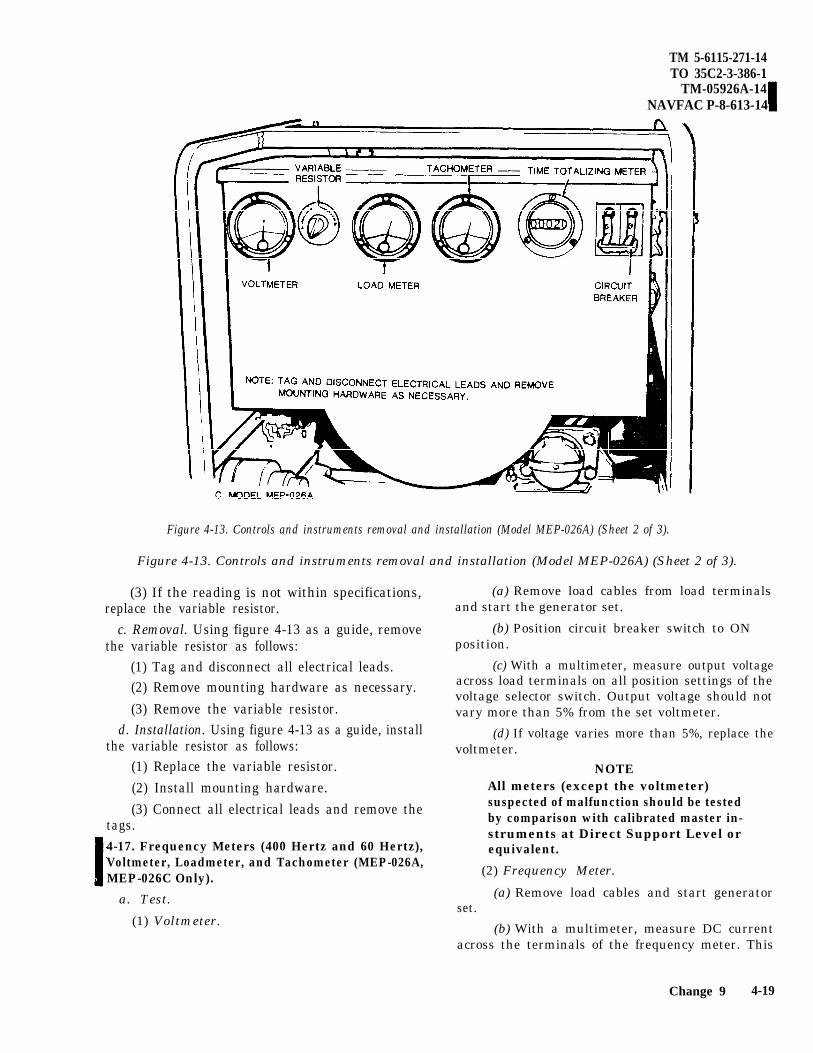
TM 5-6115-271-14TO 35C2-3-386-1
TM-05926A-14NAVFAC P-8-613-14
Figure 4-13. Controls and instruments removal and installation (Model MEP-026A) (Sheet 2 of 3).
Figure 4-13. Controls and instruments removal and installation (Model MEP-026A) (Sheet 2 of 3).
(3) If the reading is not within specifications,replace the variable resistor.
c. Removal. Using figure 4-13 as a guide, removethe variable resistor as follows:
(1) Tag and disconnect all electrical leads.(2) Remove mounting hardware as necessary.(3) Remove the variable resistor.
d. Installation. Using figure 4-13 as a guide, installthe variable resistor as follows:
(1) Replace the variable resistor.(2) Install mounting hardware.(3) Connect all electrical leads and remove the
tags.4-17. Frequency Meters (400 Hertz and 60 Hertz),Voltmeter, Loadmeter, and Tachometer (MEP-026A,MEP-026C Only).
a. Test.
(1) Voltmeter.
(a) Remove load cables from load terminalsand start the generator set.
(b) Position circuit breaker switch to ONposition.
(c) With a multimeter, measure output voltageacross load terminals on all position settings of thevoltage selector switch. Output voltage should notvary more than 5% from the set voltmeter.
(d) If voltage varies more than 5%, replace thevoltmeter.
NOTEAll meters (except the voltmeter)suspected of malfunction should be testedby comparison with calibrated master in-struments at Direct Support Level orequivalent.
(2) Frequency Meter.
(a) Remove load cables and start generatorset.
(b) With a multimeter, measure DC currentacross the terminals of the frequency meter. This
Change 9 4-19

TM 5-6115-271-14TO 35C2-3-386-1TM 05926A-14NAVFAC P-8-613-14
Figure 4-13. Controls and instruments, removal and installation (Model MEP-016A) (Sheet 3 of 3).
reading will be in DC micro amperes. Reading atminimum deflection at full scale valve will be 0 to 200micro amperes. Normal reading to 60 Hz or 400 Hzwill be 90 to 110 micro amperes.
(c) If reading is not within specifications, stopthe generator and connect a frequency meter of knownaccuracy in series with the set frequency meter. Besure to observe polarity.
(d) Restart the generator set and compare thereading on the set meter and test meter. Frequencyvariation between these two meters should not exceed1%.
(e) If frequency variation exceeds 1% of fullvalve, replace the frequency meter.
(3) Load Meter .
(a) Connect a load of known wattageproper voltage to the output terminals of generator set. Maximum load is 3000 watts.
andthe
(b) Start the generator and put circuit breakerin the ON position. Observe reading on set load meter.Meters should indicate according to load attached,i.e., 750 watts—25%, 1500 watts—50%, etc.
(c) If load meter does not read within specifica-tions, replace the load meter.
b. Removal.
(1) Open or remove the control box cover (para4-15).
(2) Refer to figure 4-13 to remove any of themeters as required.
c. Installation.
(1) Refer to figure 4-13 to install any of themeters as required.
(2) Install the control box cover (para 4-15).
4-20

TM 5-6115-271-14TO 35C2-3-386-1
TM-05926A-14NAVFAC P-8-613-14
Figure 4-14. Fuseholder, removal and installation.
4-18. Time Totalizing Meter
NOTEDouble check that correct meter is being in-stalled when it needs replacing. AC hourmeters and DC hour meters are notinterchangeable.
a. Test. Test the time totalizing meter by checkingit against a reliable clock. Check mission durationtime against the time totalizing meter.
b. Removal and Installation. To remove or installthe time totalizing meter, open or remove the controlbox cover (para 4-15) and refer to figure 4-13.
4-19. Fuseholder (Model MEP-016A, MEP-016C)
Refer to paragraph 4-15 and open or remove the con-trol box cover. Refer to figure 4-14 and the followinginstructions to remove or install the fuseholder.
a. Removal.
(1) Tag and disconnect the electrical leads fromthe fuseholder.
(2) Remove the nut over the body of thefuseholder and remove the fuseholder from the out-side of the control box.
b. Installation.
(1) From the outside of the control box, replacethe fuseholder and install the nut over the body of thefuseholder.
(2) Connect all electrical leads and remove thetags.
4-20. Field Flash Switch
a. General. Models of the generator set manufac-tured prior to 1968 are equipped with a field flashswitch. This paragraph contains instructions for test,removal and installation of the switch if the generatorset is so equipped, and for flashing the generator fieldswith or without a field flash switch.
b. Test. If the field flash switch does not work,refer to manual field flashing instructions inparagraph 4-20 (2) below. If the field can be flashedmanually, replace the switch.
Change 9 4-21

TM 5-6115-271-14TO 35C2-3-386-1TM-05926A-14NAVFAC P-8-613-14
c. Removal.(1) Open or remove the control box cover (para
4-15).(2) Tag and disconnect electrical leads as
necessary.(3) Remove the necessary mounting hardware.
d. Installation.(1) Install mounting hardware.(2) Connect electrical leads and remove tags.(3) Close or install the control box cover (para
4-15).e. Flashing the Fields.
(1) Flashing the field with the switch.
WARNINGOperation of this equipment presents anoise hazard to personnel in the area. Thenoise level exceeds the allowable limits forunprotected personnel. Wear ear muffs orear plugs which were fitted by a trainedprofessional.(a) Start the generator set (para 2-2b).(b) Actuate the switch momentarily only to
flash fields.(2) Flashing the field without a switch.
(a) Open or remove the control box cover (para4-15).
(b) Connect two 1.5 volt flashlight batteries inseries and connect a wire to each end.
(c) Connect the positive wire from the bat-teries to terminal No. 20 on the voltage regulator.
(d) Start the generator set (para 2-2b).(e) Momentarily touch the negative wire to
terminal No. 21 on the voltage regulator to flash thefield.
4-21. Current Selector Switch and Voltage Selec-tor Switch (Models MEP-016A, MEP-016C,and MEP-021A, MEP-021C).
a. Test.(1) Current selector switch.
(a) Stop the generator set.(b) Disconnect the input lead at terminal 11.
With a multimeter, check continuity between ter-minals 11 and 12 (I(1)), 11 and 13 (I(2)), 11 and 14 (I(3),on all three positions of the current selector switch.
(c) If an open circuit is indicated on selectedswitch settings, switch is defective and should bereplaced.
(2) Voltage selector switch.
(a) Disconnect load cables, start generator setand allow it to warm up.
(b) Put circuit breaker in the ON position.Check reading on voltage selector switch andvoltmeter. With a multimeter, measure outputvoltage across load terminals that are compatible tothe setting on the voltage selector switch.
(c) If proper voltages cannot be read on outputterminals, replace the voltage selector switch.
b. Removal and Installation. Refer to figure 4-13to remove or install the current selector switch orvoltage selector switch.
4-22. Slave Receptacle (Model MEP-026A, MEP-026C)
a. General. The slave receptacle is used for elec-trical power source when starter kit is mounted onunit.
b. On 28 VDC Model MEP-026A the slave recep-tacle is used for providing an output of 28 VDC forequipment which requires direct current source ofpower.
c. Refer to Figure 4-15 for removal and installationof slave receptacle.
4-23. Connector Cover Plate and Recptacle Con- nector (Model MEP-016A, MEP-016C)
a. General. The receptacle connector on the side ofthe unit has two two-pronged receptacles for opera-tion of appliances or equipment requiring 100/120volts, 15 amperes current at 60 hertz. The two recep-tacles are individually covered with a snap-up metallid. The circuit is fused against overload, but close at-tention should be paid to the indication on the loadmeter when an additional current draw is applied.
b. Test.(1) With a voltmeter, measure the input voltage
across input terminals on the back of the receptacle.This reading should be 120 V AC.
(2) Measure output voltage of plug-in on thefront of the receptacle. If 120 V is not obtained fromthe plug-in side of the receptacle, replace thereceptacle.
c. Removal. With the control box cover opened orremoved, refer to figure 4-16 to remove or install theconnector cover plate and the receptacle connector.
(1) Tag and disconnect all electrical leads.(2) Remove the two nuts, lockwashers, and
screws from inside the control box.(3) Remove the connector.
d. Installation.
4-22 Change 9
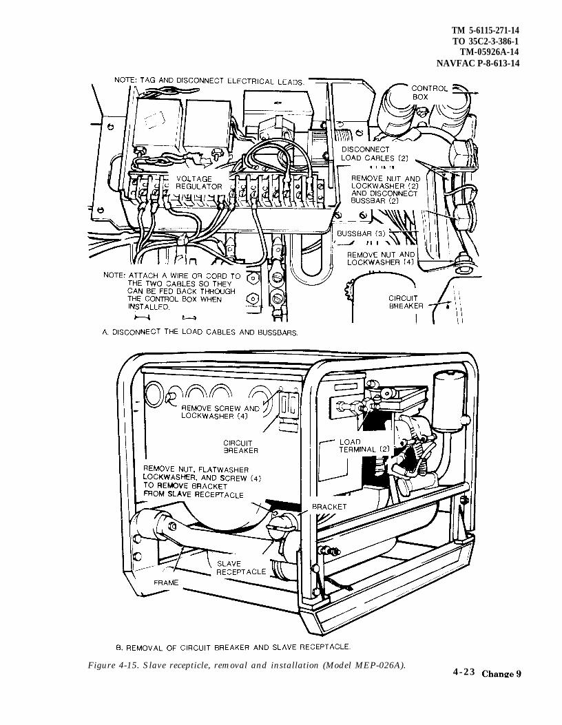
TM 5-6115-271-14TO 35C2-3-386-1
TM-05926A-14NAVFAC P-8-613-14
Figure 4-15. Slave recepticle, removal and installation (Model MEP-026A).4-23

NAVFAC P-8-613-14
TM 5-6115-271-14TO 35C2-3-386-1TM 05926A-14
Figure 4-16. Connector cover plate and receptacle connector, removal and installation (Model MEP-016A).
(1) Replace the connector.
(2) Install the two nuts, lockwashers, and screwsfrom inside the control box.
(3) Connect all electrical leads and remove alltags.
4-24. External Shunt, Bussbars and Load Terminals(Model MEP-026A, MEP-026C)
a. Removal.
(1) Open or remove the control box cover (para4-15).
(2) Refer to figure 4-17 to inspect and remove theexternal shunt, bussbars, and load terminals.
b. Installation.
(1) Refer to figure 4-17 to install the externalshunt, bussbars, and load terminals.
(2) Replace the control box cover (para 4-15),
4-24 Change 9
4-25. Load Terminals and Insulator (ModelMEP-016A, MEP-016C)
Refer to figure 4-18 to remove or install the load ter-minals and insulator as follows:
a. Removal.
(1) Tag and disconnect all electrical leads.
(2) Remove the four screws.
(3) Following removal of the mounting hard-ware, pull the terminal block from the control box.
b. Installation.
(1) Replace the terminal block.
(2) Replace the four screws.
(3) Connect all electrical leads and remove thetags.
NOTEThe load terminals and insulator for ModelMEP-021A, MEP-021C are removed and in-stalled in a similar manner.

4-25A. Replace Lost or Broken Terminal Clip (Re-tainer, Safety Clip)
The terminal clip is a component of both the loadterminal and the ground terminal. If the terminal clipis lost or broken, fabricate as follows: Requisition bulkwire as stated in the chart. Cut off about 3 inches ofthe wire, Cut the wire short enough to keep the clipsfrom touching another terminal or the generatorframe in the open or closed position. Slip the wirethrough the hole in the terminal and proceed as shownin the views below.
TM 5-6115-271-14TO 35C2-3-386-1
TM-05926A-14NAVFAC P-8-613-14
I MEP-016A/CNSN MEP-026A/C MEP-021A/C
9505-00-804-3814 Ground Load and(0.042 inch) Ground
9505-01-049-0144 Load -
(0.050 inch)
BULK WIRE CHART
Change 9 4-24.1/(4-24.2 blank)


TM 5-6115-271-14TO 35C2-3–386-1
Figure 4-17. External shunt, bussbars, and load teminals, removal and installation (Model MEP-026A).
4 - 2 5

TM 5-6115-271-14TO 35C2-3-386-1
Figure 4-18. had terminals and insulator, removal and installation (Model MEP-016A).
Section IX. MAINTENANCE OF THE FUEL SYSTEM
4-26. General (3) Refer to figure 4-12 and remove the fueltank.
This section includes maintenance instructionsfor the fuel tank, fuel hose, fuel line, fuel selector b. Inspect. Inspect the fuel tank for dents,valve, fuel filter, and fuel filter bracket. cracks, or other damage. Replace if necessary.
4-27. Fuel Tank c. Installation.
a. Removal. (1) Refer to figure 4-12 and install the fuel
(1) Remove the fuel tank drain plug (located tank.
on the fuel tank at the engine end of the genera- (2) Refer to figure 4-19 and connect the fuel
tor set) and drain the fuel tank. hose.
(2) Refer to figure 4-19 and disconnect the fuel (3) Install the fuel tank drain plug and fill the
hose. fuel tank (para 4-lb(2)).
4 - 2 6
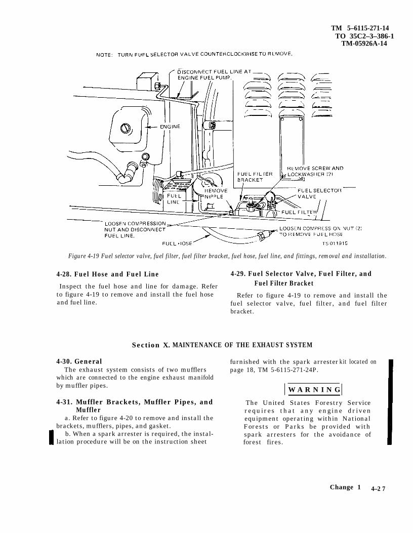
TM 5–6115-271-14TO 35C2–3–386-1
TM-05926A-14
Figure 4-19 Fuel selector valve, fuel filter, fuel filter bracket, fuel hose, fuel line, and fittings, removal and installation.
4-28. Fuel Hose and Fuel Line 4-29. Fuel Selector Valve, Fuel Filter, and
Inspect the fuel hose and line for damage. Refer Fuel Filter Bracketto figure 4-19 to remove and install the fuel hose Refer to figure 4-19 to remove and install theand fuel line. fuel selector valve, fuel filter, and fuel filter
bracket.
Section X. MAINTENANCE OF THE EXHAUST SYSTEM
4-30. General furnished with the spark arresterThe exhaust system consists of two mufflers page 18, TM 5-6115-271-24P.
which are connected to the engine exhaust manifoldby muffler pipes.
kit located on
W A R N I N G
4-31. Muffler Brackets, Muffler Pipes, and The United States Forestry ServiceMuffler requires that any engine driven
a. Refer to figure 4-20 to remove and install the equipment operating within Nationalbrackets, mufflers, pipes, and gasket. Forests or Parks be provided with
b. When a spark arrester is required, the instal- spark arresters for the avoidance oflation procedure will be on the instruction sheet forest fires.
Change 1 4–2 7

TM 5-6115-271-14TO 35C2–3–386-1
Figure 4-20. Muffler bracket, mufflers, and muffler pipes, removaland installation.
Section XI. MAINTENANCE OF THE ENGINE ELECTRICAL SYSTEM
4-32. General 4-33. Starter
The engine electrical system consists of a recep- a. General. Check starter for proper cable con-tacle, starting switch, mounting bracket, electric nections and loose terminals. Check the conditionstarter, and the necessary wiring. When condi- of the battery. If the starter fails to crank engine,tions prevent manual starting, or when the unit is replace starter.operated in extremely cold weather, the electrical b. Removal.starter kit can be installed on the unit. Connect (1) Remove the right exhaust manifold andthe 24-volt power supply of a vehicle or other No. 1 and 3 spark plugs.external power source to the receptacle to start (2) Refer to figure 4-21 and remove thethe unit electrically. starter.
4-28

TM 5-6115-271-14TO 35C2–3–386-1
Figure 4-21. Starter, removal and installation.
Figure 4–22. Starting Switch, Receptacle, and bracket, removal and installation.
c. Installation. 4-34. Starting Switch, Receptacle, and(1) Refer to figure 4-21 and install the starter. Bracket(2) Install No. 1 and 3 spark plugs and the Refer to figure 4-22 and remove and install the
right exhaust manifold. starting switch, receptacle, and bracket.
4-29


TM 5-6115-271-14TO 35C2-3-386-1
TM-05926A-14NAVFAC P-8-613-14
CHAPTER 5INTERMEDIATE (FIELD), (DIRECT SUPPORT AND GENERAL SUPPORT) AND
DEPOT MAINTENANCE INSTRUCTIONS
Section I. REPAIR PARTS, SPECIAL TOOLS AND EQUIPMENT
5-1. Tools and Equipment General Support) and Depot Maintenance Repair
No special tools or equipment are required at in- Parts and Special Tools
termediate (field), (direct support and general support) Maintenance repair parts list for intermediateand depot maintenance levels. (field), (direct support and general support) and depot
5-2. Intermediate (Field), (Direct Support and Maintenance of the generator and engine are contain-ed in the appropriate service manuals (See Appendix A).
Section II. TROUBLESHOOTING
5-3. General
This section contains troubleshooting or malfunc-tion information and test for locating and correctingmost of the troubles which may develop in thegenerator sets. Each malfunction or trouble symptomfor an individual component, unit, or system is follow-ed by a list of tests or inspections necessary for youto determine probable causes and suggested correc-tive actions for you to remedy the malfunction.
5-4. Troubleshooting
a. This manual cannot list all possible malfunc-tions that may occur or all tests or inspections, andcorrective actions. If a malfunction is not listed (ex-cept when malfunction and cause are obvious), or isnot corrected by listed corrective actions, you shouldnotify higher level maintenance.
b. Table 5-1 lists the common malfunctions thatyou may find during the operation or maintenance ofthe generator sets or their components. You shouldperform the tests/inspections and corrective actionsin the order listed.
NOTEBefore you use this table, be sure you haveperformed all normal operational checks. Ifyou have a malfunction which is not listedin this table, notify the next higher level ofmaintenance.
Air Force users may perform maintenancewithin the scope of their capability.
Table 5-1. Troubleshooting
MALFUNCTIONTEST OR INSPECTION
CORRECTIVE ACTION
1. GENERATOR FAILS TO BUILD UP RATEDVOLTAGE
Step 1. Inspect the voltage regulator for loosewires, corroded wiring, metal to metal con-tact, incorrect wiring, or other damage.Test voltage regulator for proper voltagerequirements as follows:
a. Voltage Regulator Testing (ACUnit).
(1) Place output selector switch ondesired test setting and disconnect loadcables.
(2) Start generator set. Place circuitbreaker in ON position and check outputselector switch to indicate load terminalswhere output voltage is applied.
(3) Check set voltmeter for correctsetting. Using a multimeter, check loadterminals to verify reading on setvoltmeter. If voltage is low and thevariable resistor will not correct the defi-ciency, check exciter voltage across ter-minals 20 and 21 on the voltage regulatorterminal board. This voltage will vary butshould be about 30 volts. If voltage at ter-minals 20 and 21 of the voltage regulatorterminal board fails to meet specifications,the voltage regulator is defective andshould be fully tested and repaired (seepara 8-3).
(4) Using a multimeter as a checkagainst the set voltmeter, test the outputof the generator set on all position settingsof the voltage selector switch.
5-1

TM 5-6115-271-14TO 35C2-3-386-1TM-05926A-14NAVFAC P-8-613-14
Table 5-1. Troubleshooting (Cont’d) Table 5-1. Troubleshooting (Cont’d)MALFUNCTION MALFUNCTION
TEST OR INSPECTION TEST OR INSPECTIONCORRECTIVE ACTION
1. GENERATOR FAILS TO BUILD UP RATEDVOLTAGE (Cont’d)
(5) Stop the generator set, and connectthe load cables.
(6) Repeat steps (2) through (4) above.b. Voltage Regulator Testing (DC Unit).
(1) Disconnect load cables and turn cir-cuit breaker switch to OFF position.
(2) Start generator set, place circuitbreaker switch to ON position and observe setvoltmeter and tachometer for proper reading(should be 28 V at 3600 RPM).
(3) Using a multimeter, check load ter-minals to verify reading on set voltmeter. Ifvoltage is low, adjust it to specifications withthe variable resistor.
(4) If the voltage is still low and the var-iable resistor will not correct the deficiency,check exciter voltage across terminals 20 and21 of the voltage regulator terminal board.This voltage will vary but should be about 30volts. If voltage at terminals 20 and 21 of thevoltage regulator terminal board fails to meetspecifications, the voltage regulator is defec-tive and should be fully tested and repaired(see para 8-3),
(5) If voltage is satisfactory, stop thegenerator set and attach the load cables.
(6) Repeat steps (2) through (4) above.Repair a defective voltage regulator (para
8-3).Step 2. Inspect the exciter rotor for loose connections
or breaks. Test the exciter rotor as follows:a. Model MEP-021A, MEP-021C
(1) Start generator set and allow it towarm up.
(2) Observe the voltmeter on the front ofthe control box. If exciter, rotor, or stator isdefective there will be no voltage reading onthe set voltmeter.
(3) Manually flash the field windings asprescribed in paragraph 4-20e(2). If stator androtor are good, voltage will appear and hold onset voltmeter, with 100% load applied.
(4) If voltage comes up, proceed withgenerator operation. If not, stop the engineand check continuity of exciter stator byloosening terminal 20 or 21 on the voltageregulator terminal board and measure acrossthe exciter stator leads with a multimeter. Ifbad, then replace the stator assembly.
(5) Remove generator from generator set(para 6-4), and remove the rotor assembly (para10-2) from the stator assembly. Remove diodesfrom the exciter rotor (17, fig. 10-4) and testwith a multimeter. Replace any bad diodes. Ifdiodes are good, replace the rotor assembly,
CORRECTIVE ACTION1. GENERATOR FAILS TO BUILD UP RATED
VOLTAGE (Cont’d)(6) Reassemble generator set and repeat
steps (1) and (2).b. Models MEP-016A, MEP-016C and
MEP-026A, MEP-026C(1) Start generator set and allow it to
warm up.(2) Observe the voltmeter on the front of
the control box. If exciter, rotor, or stator isdefective, there will be no voltage reading onthe set voltmeter.
(3) Manually flash the field windings asprescribed in paragraph 4-20e(2), If stator androtor are good, voltage will appear and hold onset voltmeter, with 100% load applied.
(4) If voltage comes up, proceed withgenerator operation. If not, stop the engineand check continuity of exciter stator byloosening terminal 20 or 21 on the voltageregulator terminal board and measure acrossthe exciter stator leads with a multimeter. Ifbad, then replace the stator assembly.
(5) Remove generator from generator set(para 6-4), and remove the rotor assembly (para10-2), from the stator assembly. Removediodes from the exciter rotor (20, fig. 10-5) andtest with a multimeter. Replace any baddiodes. If diodes are good, replace the rotorassembly.
(6) Reassemble generator set and repeatsteps (1) and (2).
Replace a defective exciter rotor (para10-2).
Step 3. Inspect the stator and rotor for loose connec-tions or breaks. Test the stator and rotor (seemalfunction 1, step 2).
Replace the stator and/or rotor (para 10-2).
2. GENERATOR VOLTAGE TOO HIGHInspect the voltage regulator for loose wires, corrod-
ed wiring, metal-to-metal contact, incorrect wiring, orother darmage. See malfunction 1, step 1 and test thevoltage regulator.
Repair a defective voltage regulator (para8-3).
3. GENERATOR FAILS TO SUPPLY LOADStep 1.
Step 2.
Step 3.
Inspect the stator for loose connections orbreaks, Refer to malfunction 1, step 2 and test the rotor.
Redate a defective stator (para 10-2).Check the rotor for loose connections orbreaks. Refer to malfunction 1, step 2 and testthe rotor.
Replace the rotor (para 10-2).Inspect the voltage regulator for loose wires,corroded wiring, metal to metal contact, incor-rect wiring, or other damage. Refer to malfunc-tion 1, step 1 and test the voltage regulator.
Repair a defective voltage regulator (para8-3).
5 - 2

Table 5-1. Troubleshooting (Cont’d)
MALFUNCTIONTEST OR INSPECTION
CORRECTIVE ACTION3. GENERATOR FAILS TO SUPPLY LOAD
(Cont’d)Step 4. Test the circuit breaker as follows:
a. Attach a variable load to output ter-minals and start the generator set.
b. Move circuit breaker to ON positionand observe load meter and voltmeter.Reading at redline on load meter is 100%load. Circuit breaker should stay on in-definitely under 100% load.
c. Adjust variable load until load meterreads in red portion of load meter. Circuitbreaker should trip when indicator entersred portion of load meter.
If circuit breaker trips below max-imum load (100% of 0.8 PF), (Power Fac-tor), replace the circuit breaker (para 8-8).
4. GENERATOR FREQUENCY FLUCTUATESOR DROPS UNDER LOAD (Models
MEP-016A/C and MEP-021A/C) S t e p 1 . Inspect the engine to see if it is lacking
TM 5-6115-271-14TO 35C2-3-386-1
TM-05926A-14NAVFAC P-8-613-14
Table 5-1. Troubleshooting (Cont’d)
MALFUNCTIONTEST OR INSPECTION
CORRECTIVE ACTION4. GENERATOR FREQUENCY FLUCTUATES
OR DROPS UNDER LOAD (ModelsMEP-016A/C and MEP-021A/C) (Cont’d)
b. The generator will shut down.(1) Adjust the governor (fig. 5-1).
(a) Start the generator.(b) Place the governor control in
the govern position.(2) Refer to appropriate service
manual in Appendix A for other correctiveaction.
Step 2. Check the engine for out of adjustment or
power. Some indications are:a. Generator will not achieve its rated
voltage.
defects. The frequency and load meterswill fluctuate and then drop off.
Adjust (fig. 5-1) or replace the gover-nor (see appropriate service manual in Ap-pendix A).
5. GENERATOR NOISYInspect for a defective bearing.a. On models manufactured prior to 1968, check
the bearing by removing the control box access cover(fig. 5-2).
(1) Remove the three screws and lockwashers.(2) Remove the control box access cover.
(b) On models manufactured after 1968, tear downthe generator (para 10-2) and visually inspect thebearing.
c. Examine the bearing for signs of wear ordiscoloration.
Replace a defective bearing (para 10-2).
Figure 5-1. Adjusting Governor Control. Figure 5-2. Removing control box access cover.
Section III. GENERAL MAINTENANCEThe maintenance to be performed by intermediate (field), (direct support and general support) and depot
maintenance personnel on this equipment is limited to repair of the frame. Repair is accomplished by straighten-ing bends using the furnished cutting and welding torch outfit or by replacement.
Change 9 5-3/(5-4 blank)


TM 5-6115-271-14TO 35C2-3-386-1
TM-05926A-14NAVFAC P-8-613-14
CHAPTER 6
REMOVAL/lNSTALLATION OF MAJOR COMPONENTS
Section I. GENERAL
This chapter contains removal and installation instructions for the major components. The three major com-ponents are the control box assembly, the generator and the engine.
A. GENERATOR HOUSING REMOVAL.
Figure 6-1. Generator, Removal and Installation (Sheet 1 of 2).
Section Il. ENGINE
6-1. Engine b. Installation,
a. Removal.(1) Refer to figure 6-2 and install the engine.(2) Install the generator (fig. 6-1).
(1) Remove the starting switch, receptacle, and (3) Install the fuel tank (A, fig. 4-12).bracket if installed (fig. 4-22). (4) Connect the fuel line (fig. 4-19).
(2) Disconnect the fuel Line (fig. 4-19). (5) Install the starting switch, receptacle, and(3) Remove the fuel tank (A, fig. 4-12). bracket if removed (fig, 4-22).(4) Remove the generator (fig. 6-1).(5) Refer to figure 6-2 and remove the engine.
NOTEWhen a model 4A032-1 or 4A032.2 engine is replaced with a model 4A032.3 engine theGenerator Set ID plate must also be replaced, changing the MEP-OXXA number toMEP-OXXC. NSN on the plate as well as on accountable (including maintenance)records must also be changed.
6-1

TM 5-6115-271-14TO 35C2-3-386-1TM 05926A-14NAVFAC P-8-613-14
Figure 6-1. Generator, removal and installation (sheet 2 of 2).
Figure 6-2. Engine, removal and installation.
Section III. CONTROL BOX ASSEMBLY
6-2. General the control box. These controls and instruments
All the controls and instruments necessary forinclude the voltage regulator, frequency con-
the operation of the generator are contained inverter, output selector switch, current trans-former, diode rectifier and terminal board, fixed
6-2

Figure 6-3
TM
5-6115-271-14T
O 35C
2-3-386-1T
M-05926A
-14N
AV
FAC
P-8-613-14
6-3

TM 5-6115-271-14TO 35C2-3-386-1TM-05926A-14NAVFAC P-8-613-14
resistor board, heat sink, and the necessary wiringharness.
6-3. Control Box
Refer to figure 6-3 to remove and install the controlbox.
Section IV.
6-4. Generator
a. Removal.
(1) Remove the control box (fig. 6-3).
(2) Refer to figure 6-1 and remove the generator.
NOTEAlthough the interior of the generator setsmay differ slightly, the removal and the in-stallation of the control box as illustratedin this figure, is essentially the same.
GENERATOR
b. Installation.
(1) Refer to figure 6-1 and install the generator.
(2) Install the control box (fig. 6-3).
6-4 Change 9

TM 5-6115-271-14TO 35C2-3-386-1
CHAPTER 7
MAINTENANCE OF THE FRAME ASSEMBLY
7-1. General.
The frame assembly includes the engine-gener-ator support, shock mountings, and the frame.
7-2. Frame Assembly
a. Removal.(1) Remove the generator (fig. 6-1).(2) Remove the engine (fig. 6-2).(3) Remove the ground terminal stud (A, fig.
4-12).(4) Remove the bonding strap (D, fig. 4-11).(5) Remove the fuel tank (A, fig. 4-12).(6) Refer to figure 7-1 and remove engine-
generator support, frame and shock mounts.
b. Disassembly. Refer to figure 7–2 to disassem-ble the frame.
c. Repair. Repair the upper frame as necessaryby straightening, using the furnished cutting andwelding torch outfit.
d. Reassembly. Refer to figure 7-2 and reassem-ble the frame.
e. Installation Install the frame assembly asfollows:
(1) Refer to figure 7-1 and install engine-generator support, frame, and shock mounts.
(2) Install the fuel tank (A, fig. 4-12).(3) Install the bonding strap (D, fig. 4-11).(4) Install the ground terminal stud (A, fig. 4-
12).(5) Install the engine (fig. 6-2).(6) Install the generator (fig. 6-1).
7-1

FIG
UR
E 7-1.
TM
5-6115-271-14
TO
35C
2–3–386-1
7-2

TM 5-6115-271-14TO 35C2-3-386-1
Figure 7–2. Frame, disassembly and reassembly. 7-3

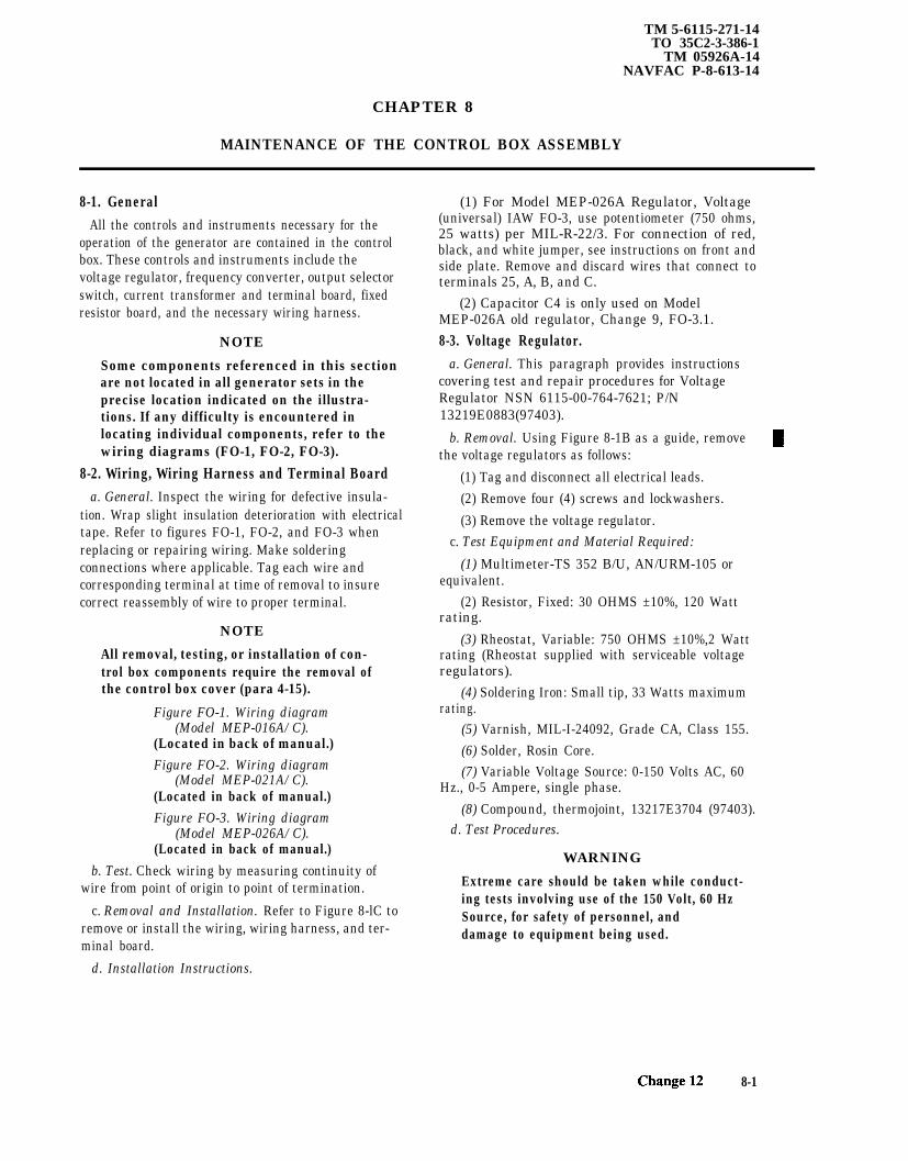
TM 5-6115-271-14TO 35C2-3-386-1
TM 05926A-14NAVFAC P-8-613-14
CHAPTER 8
MAINTENANCE OF THE CONTROL BOX ASSEMBLY
8-1. GeneralAll the controls and instruments necessary for the
operation of the generator are contained in the controlbox. These controls and instruments include thevoltage regulator, frequency converter, output selectorswitch, current transformer and terminal board, fixedresistor board, and the necessary wiring harness.
NOTE
Some components referenced in this sectionare not located in all generator sets in theprecise location indicated on the illustra-tions. If any difficulty is encountered inlocating individual components, refer to thewiring diagrams (FO-1, FO-2, FO-3).
8-2. Wiring, Wiring Harness and Terminal Boarda. General. Inspect the wiring for defective insula-
tion. Wrap slight insulation deterioration with electricaltape. Refer to figures FO-1, FO-2, and FO-3 whenreplacing or repairing wiring. Make solderingconnections where applicable. Tag each wire andcorresponding terminal at time of removal to insurecorrect reassembly of wire to proper terminal.
NOTE
All removal, testing, or installation of con-trol box components require the removal ofthe control box cover (para 4-15).
Figure FO-1. Wiring diagram(Model MEP-016A/C).
(Located in back of manual.)Figure FO-2. Wiring diagram
(Model MEP-021A/C).(Located in back of manual.)Figure FO-3. Wiring diagram
(Model MEP-026A/C).(Located in back of manual.)
b. Test. Check wiring by measuring continuity ofwire from point of origin to point of termination.
c. Removal and Installation. Refer to Figure 8-lC toremove or install the wiring, wiring harness, and ter-minal board.
d. Installation Instructions.
(1) For Model MEP-026A Regulator, Voltage(universal) IAW FO-3, use potentiometer (750 ohms,25 watts) per MIL-R-22/3. For connection of red,black, and white jumper, see instructions on front andside plate. Remove and discard wires that connect toterminals 25, A, B, and C.
(2) Capacitor C4 is only used on ModelMEP-026A old regulator, Change 9, FO-3.1.8-3. Voltage Regulator.
a. General. This paragraph provides instructionscovering test and repair procedures for VoltageRegulator NSN 6115-00-764-7621; P/N13219E0883(97403).
b. Removal. Using Figure 8-1B as a guide, removethe voltage regulators as follows:
(1) Tag and disconnect all electrical leads.(2) Remove four (4) screws and lockwashers.
(3) Remove the voltage regulator.c. Test Equipment and Material Required:
(1) Multimeter-TS 352 B/U, AN/URM-105 orequivalent.
(2) Resistor, Fixed: 30 OHMS ±10%, 120 Wattrating.
(3) Rheostat, Variable: 750 OHMS ±10%,2 Wattrating (Rheostat supplied with serviceable voltageregulators).
(4) Soldering Iron: Small tip, 33 Watts maximumrating.
(5) Varnish, MIL-I-24092, Grade CA, Class 155.(6) Solder, Rosin Core.(7) Variable Voltage Source: 0-150 Volts AC, 60
Hz., 0-5 Ampere, single phase.(8) Compound, thermojoint, 13217E3704 (97403).
d. Test Procedures.
WARNING
Extreme care should be taken while conduct-ing tests involving use of the 150 Volt, 60 HzSource, for safety of personnel, anddamage to equipment being used.
8-1

TM5-6115-271-14TO 35C2-3-386-1TM 05926A-14NAVFAC P-8-613-14
CAUTIONWhile using a soldering iron, caution shouldbe taken to prevent damage to components andprinted circuit board from excessive orprolonged applied heat. Damage could result toreplacement items, rendering them unsuitablefor operation.
(1) Remove voltage regulator, refer to step bRemoval.
(2) Test power transistor Q2.(a) Locate power transistor Q2 (1, Figure 8-1)
on the back of the voltage regulator housing
Figure 8-1. Voltage Regulator Testing.
*U.S. GOVERNMENT PRINTING OFFICE: 1993- 755-028/80242 PIN: 025150-0128-2 Change 12

TM 5-6115-271-14TO 35C2-3-386-1
TM-05926A-14NAVFAC P-8-613-14
(b) Remove screws (2) and washers (3) CAUTIONsecuring Q2 to housing.
Do not remove the white heat sink paste(c) Pull transistor (1) straight from hous- from the mica insulator, transistor, or regu-
ing, being careful not to damage the mica insulator later housing. If this compound is removedunder the transistor. transistor Q2 will overheat and become dam-
aged.
(d) Test transistor with a multimeter (setto read ohms). Refer to Figure 8-1A and Table 8-1.Multimeter (+) and (–) refer to the multimeter testleads.
Figure 8-1A. Q1 and Q2 transistor pin out locations.
Table 8-1. Q2 Test Chart.
Multimeter ( + ) Multimeter ( – ) Meter Reading
Collector Emitter Infinite (oo)Collector Base Infinite (oo)Emitter Collector Infinite (oo)Base Collector 1 to 50 ohmsBase Emitter 1 to 50 ohmsEmitter Base Infinite (oo)
(e) Readings other than those listed in (3) Remove terminal strip TB1.Table 8-1 indicate either an open or shorted junctionwithin Q2 and Q2 should be replaced. (a) Remove two screws (4, Figure 8-1 )
that secure terminal strip TB1 (5).NOTE
(b) Gently pull terminal strip TB1 (5)Do not install transistor Q2 at this time. along with the printed circuit board upward.With Q2 removed, transistor Q1 can betested without removal of the transistor fromthe printed circuit board.
8-3

TM 5-6115-271-14TO 35C2-3-386-1TM-05926A-14NAVFAC P-8-613-14
(4) Test diode CR5.
(a) Locate diode CR5 located on circuitboard.
(b) Test diode CR5 with a multimeter (setto read ohms). Measure resistance across CR5, reversetest leads, and measure resistance again.
(c) Resistance should be low (1 to 50ohms) one way and infinite (oo) resistance the otherway.
(d) If low or high resistance is measuredin both directions diode CR5 should be replaced.
(5) Test current regulating diode CR6.
(a) Locate diode CR6 located on circuitboard.
(b) Unsolder and lift one end of diodeCR6 from the printed circuit board.
(c) Test diode CR6 with a multimeter (setto read ohms). Measure resistance across CR6, reversetest leads, and measure resistance again.
(d) Resistance should be low (1 to 50ohms) one way and greater than 500 ohms resistancethe other way.
(e) If low or high resistance is measuredin both directions diode CR6 should be replaced.
Table 8-2. Q1 Test Chart.
NOTE
Do not install diode CR6 lead to printedcircuit board until transistor Q1 has beentested.
(6) Test diode CR7.
(a) Locate diode CR7 on circuit board.
(b) Test diode CR7 with a multimeter (setto read ohms). Measure resistance across CR7, reversetest leads, and measure resistance again.
(c) Resistance should be low (1 to 50ohms) one way and infinite (00) resistance the otherway.
(d) If low or high resistance is measuredin both directions, diode CR7 should be replaced.
(7) Test transistor Q1.
(a) Make sure that transistor Q2 is stillremoved and that one lead of diode CR6 is unattachedto the printed circuit board.
(b) Locate power transistor Q1 on theprinted circuit board.
(c) Test transistor with a multimeter (setto read ohms). Refer to Figure 8-1A and Table 8-2.Multimeter (+) and(–) refer to the multimeter testleads.
Multimeter (+) Multimeter (–) Meter Reading
Collector Emitter Infinite (oo)Collector Base Infinite (oo)Emitter Collector Infinite (oo)Base Collector 1 to 50 OhmsBase Emitter 1 to 50 OhmsEmitter Base Infinite (oo)
8-4 Change 11

(d) Resistance measurements other thanthose listed in Table 8-2 indicate an open or shortedjunction within Q1, Q1 should be replaced.
(8) Solder lead of diode CR6 to printed circuitboard.
(9) Install transistor Q2 (1, Figure 8-1) withmica insulator between Q2 and regulator housing.
(10) If necessary, apply a small amount of heatsink compound (P/N 13217E3704, FSCM 97403) totransistor Q2 and housing. Secure transistor Q2 withscrews (2) and washers (3).
(11) Make test connections.
(a) Connect a 30 ohm 120 watt resistor toterminals #21 and #20 of terminal strip TB1 (5).
(b) Obtain a 750 ohm 2 watt rheostat.
(c) Position rheostat so that control shaftis facing you and the three terminal lugs are facing up.Connect a 12-18 AWG insulated wire to the middleterminal lug and another wire to the left hand terminallug of the rheostat.
(d) Attach the two rheostat leads to termi-nals #26 and #28 of terminal strip TB1 (5). Turn therheostat clockwise to its maximum rotation.
(e) Connect a 0-150 VAC, 60 HZ powersupply to terminals #24 and #27 of terminal strip TB1(5).
(12) Perform tests.
(a) Turn on the power supply and set for115 VAC.
(b) Set a multimeter to read a 0-50 VDCrange.
TM 5-6115-271-14TO 35C2-3-386-1
TM-05926A-14NAVFAC P-8-613-14
(c) Check for 30-35 VDC between termi-nals #20 and #21 of terminal strip TB1 (5). Terminal#20 is positive and terminal #21 is negative.
(d) Rotate the shaft of the test rheostatcounterclockwise to approximately eighty percent ofits maximum rotation. The voltage between terminals#20 and #21 of TB1 (5) should now be zero.
(e) Rotate the shaft of the test rheostatclockwise while observing the voltage at terminals #20and #21 of TBl (5).
(f) Voltage at terminals #20 and #21should be between 30 and 35 volts when test rheostatis turned to approximately eighty percent of its clock-wise rotation. If no voltage is present, refer to step (i).
(g) If there is a delay of two seconds ormore between decreases and increases of the voltage atterminals #20 and #21 or if voltage changes do notoccur at the eighty percent of maximum rotationpoints, adjust R6. Refer to (h) for adjustment proce-dure. If no delay is present and voltage changes occurat the eighty percent rotation points, testing procedureis completed. If no voltage change occurs, regardless ofthe position of the test rheostat, refer to step (i).
(h) Locate R6 on the printed circuitboard. Turning the adjustment screw of R6 clockwisewill turn the voltage at terminals #20 and #21 of TB1(5) on for a given setting of the test rheostat. Turningadjustment screw counterclockwise turns the voltageat terminals #20 and #21 off. Adjust screw as requiredto achieve voltage cutoff and turn on for eighty percentof maximum rotation as described in steps (d), (e), and(f). Troubleshooting is complete after adjustment ismade.
NOTE
Adjustment of R6 does not cause the voltageat terminals #20 and #21 of TB1 (5) to vary.Either voltage will be on or voltage will beoff.
Change 11 8-4.1

Figure 8-1B
.
TM
5-6115-271-14T
O 35C
2-3-386-1T
M-05926A
-14N
AV
FA
C P
-8-613-14
8-4.2C
hange 11
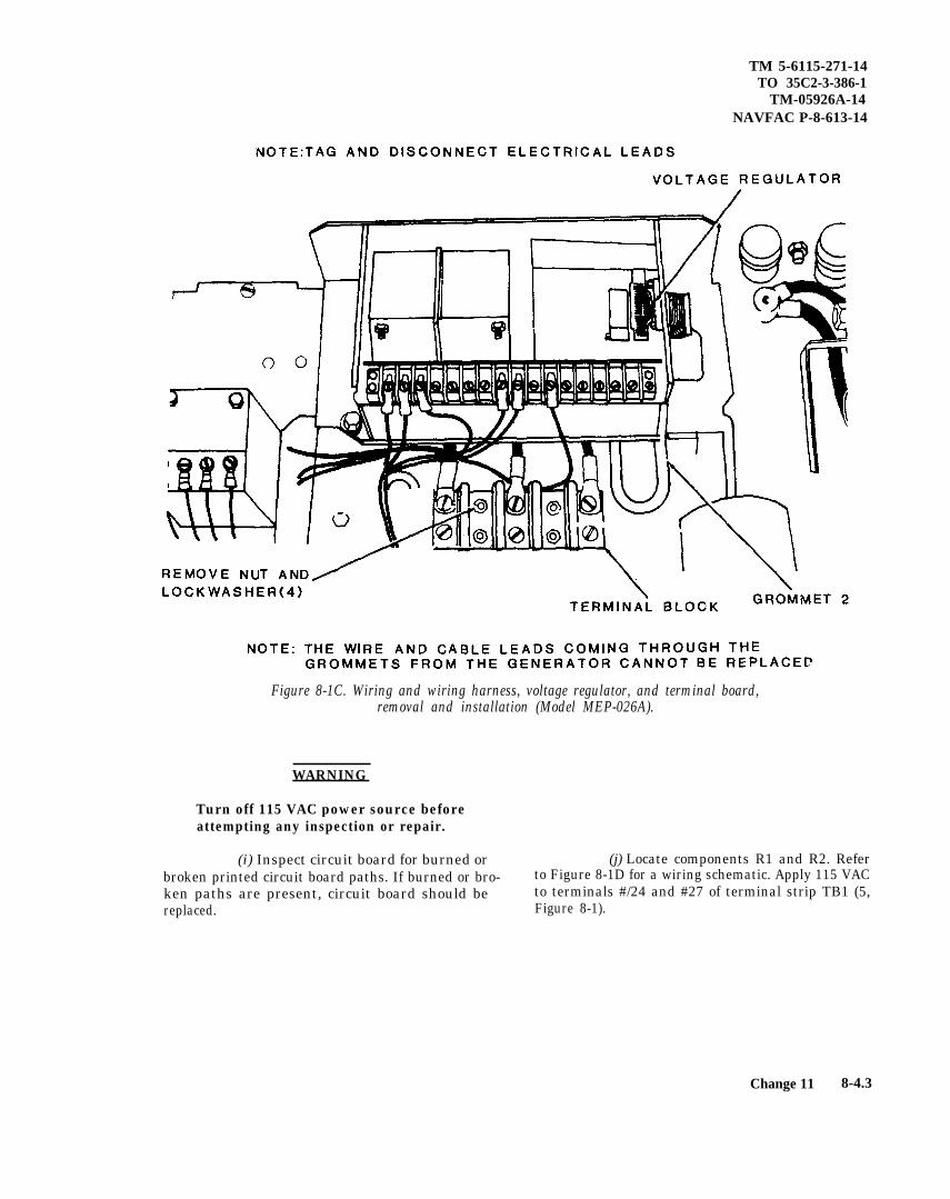
TM 5-6115-271-14TO 35C2-3-386-1
TM-05926A-14NAVFAC P-8-613-14
Figure 8-1C. Wiring and wiring harness, voltage regulator, and terminal board,removal and installation (Model MEP-026A).
Change 11 8-4.3
WARNING
Turn off 115 VAC power source beforeattempting any inspection or repair.
(i) Inspect circuit board for burned or (j) Locate components R1 and R2. Referbroken printed circuit board paths. If burned or bro- to Figure 8-1D for a wiring schematic. Apply 115 VACken paths are present, circuit board should be to terminals #/24 and #27 of terminal strip TB1 (5,replaced. Figure 8-1).

TM 5-6115-271-14TO 35C2-3-386-1TM-05926A-14NAVAC P-8-613-14
Figure 8-1D. Standard voltage regulator 3KW, 5KW, 10KW, DC, 60HZ, (1319E0883).
8-4.4 Change 11

(k) Connect a multimeter (set to read 0-50 VDC) across points “A” and “B” as indicated onwiring schematic. Connect red lead to point “A” andblack lead to point “B”.
(l) A DC voltage of 28-32 volts should beindicated. If voltage is not within this range, check thevoltage across voltage regulating (zener) diode VR1and VR2 on circuit board.
CAUTION
If either zener diode VR1 and VR2 isremoved, do not apply the 115 VAC source tothe regulator until a replacement is con-nected into the circuit. Failure of the voltageregulator will occur if this caution is notobserved.
(m) The voltage across VR1 and VR2should be approximately 14 VDC. Replace zenerdiodes that do not have a voltage drop of approxi-mately 14 VDC.
(n) After replacing zener diodes VR1and/or VR2 and no voltage is indicated across eitheror both zener diodes VR1 and VR2, check the voltageacross terminal lugs #7 and #8 of the T1 power trans-former (6).
NOTE
Change setting on multimeter to 0-50 VACrange.
(o) A voltage of 25-35 VAC should bepresent. If voltage is not present, check that 115 VACpower source is connected properly and all wiring con-nections to T1 (6) are tight. If power is properly con-nected and T1 (6) connections are tight transformerT1 (6) should be replaced.
(p) After verifying that 25-35 VAC ispresent across T1 (6) terminals #7 and #8, locatediodes CR8 and CR9 on circuit board (6).
(q) Turn off power and unsolder one endof diode CR8 and CR9. Check the resistance of eachdiode in one direction and then reverse leads and testin the other direction. Resistance should be low in onedirection and high in the other.
TM 5-6115-271-14TO 35C2-3-386-1
TM-05926A-14NAVFAC P-8-613-14
(s) Locate capacitors C1 (7) and C2 (8) onthe reverse side of the printed circuit board. Unsolderone end of each capacitor from the circuit board.
(t) Test capacitors C1 (7) and C2 (8) witha multimeter (set to read ohms) across the capacitorbeing tested and then reverse leads across capacitor.
(u) Connection of the multimeter (set forohms) across the capacitor should immediately resultin the movement of the meter pointer from the infinity(oo) side of the scale to the low ohms side of the scaleand then slowly return to the infinity (oo) side of thescale.
(v) If the capacitor is shorted or leaky, thepointer will remain on the low ohms side of the scale.If the capacitor is open, there will be no movement ofthe meter pointer. Replace open, shorted, or leakycapacitors as required.
(w) Locate zener diode VR3 on circuitboard and apply 115 VAC to terminals #24 and #27 ofthe terminal strip TB1 (5, Figure 8-1).
(x) Check the voltage across zener diodeVR3. Voltage across VR3 should be approximately 4.7VDC.
(y) If voltage across VR3 is greater than4.7 VDC, replace VR3. If no voltage is indicatedacross VR3, locate R3 (a 1K ohm resistor) on circuitboard.
(z) Disconnect the 115 VAC powersource from the regulator. Unsolder one end of R3from the circuit board. Measure the resistance of R3.Resistance should be between 900 and 1100 ohms. Ifresistor is within this range, reconnect lead. Replaceresistor if not within tolerances.
(aa) Apply the 115 VAC power to termi-nals #24 and #27 of the terminal strip TB1 (5).Recheck the voltage drop across zener diode VR2,there should be a voltage drop of 14 VDC present. If14 VDC is present and there is no voltage drop acrosszener diode VR3, VR3 should be replaced.
(bb) If none of the tests or recommendedrepairs correct the operation of the voltage regulator,entire voltage regulator should be replaced.
(r) Replace diodes CR8 or CR9 if they donot pass resistance check.
Change 11 8-4.5

TM 5-6115-271-14TO 35C2-3-386-1TM-05926A-14NAVFAC P-8-613-14
(2) Connect voltage regulator, equipment,and components as shown in Figure 8-1 E.
8-4.6 Change 11
Figure 8-1E. Voltage Regulator Adjustment Schematic
e. Adjustment.
(1) The following components and equip-ment are needed for the adjustment procedures on thevoltage regulator.
Two DC Voltmeters ±0.5 percent,0-100 VDC (M1 and M4)AC Voltmeter ± 0.5 percent, 0-150VAC (M2)Oscilloscope (M3)Voltage source 0-150 VAC 60 Hz,Regulation ± 0.25 percent, from 0-2Amps (PS1)Resistor 30 ohms, 120 watts (R1)Resistor, 750 ohms ±5 percent, 2watts (R2)Potentiometer, 500 ohms (R6)
(3) Set potentiometer R6 to 250 ohms(halfway).
(4) Turn AC power supply (PS1) on.
(5) Slowly increase AC voltage (0 to 30 VAC)while monitoring DC voltmeter (M1) and oscilloscope(M3). DC voltage reading on DC voltmeter (M1) shallincrease proportionally with the increasing AC voltageand the voltage wave form trace of oscilloscope (M3)shall move toward a positive voltage level. A voltageshall also be indicated on DC voltmeter (M4). Thewaveform trace of oscilloscope (M3) swinging belowthe zero axis (negative) during this (0-30 VAC) testshall be indicative of an unusable/defective opera-tional amplifier.
(6) Increase AC voltage for a “maximumreading” on meter (M1) (35 VDC minimum) or untiloscilloscope (M3) wave form is just starting to comeoff the “maximum level” refer to curve 1 of Figure8-1F.

Figure 8-1F. Waveforms.
TM 5-6115-271-14TO 35C2-3-386-1
TM-05926A-14NAVFAC P-8-613-14
(a) If the AC voltmeter (M2) indicates136 VAC or greater, proceed with step (7).
(b) If the AC voltmeter (M2) indicatesless than 136 VAC, proceed with step (8).
(7) Perform the following adjustment proce-dures:
(a) Adjust AC supply PSI to adjust (M2)to 136 VAC.
(b) Slowly adjust R6 clockwise until oscil-loscope (M3) wave form begins to decrease from“maximum level”. DC voltmeter (M1) reading shallgo to zero when wave form passes through zero. Referto curve 2 on Figure 8-1F.
(c) Adjust AC supply (PS1) to adjust(M2) to 133 VAC. The oscilloscope (M3) waveformshall return to maximum level and DC voltmeter (M1)shall read maximum (35 VDC minimum).
(8) Perform the following adjustment proce-dures.
(b) Slowly adjust R6 counterclockwiseuntil oscilloscope (M3) wave form begins to go upfrom “minimum level” (curve 3, Figure 8-1F). M1reading shall go to “maximum level” (35 VDC mini-mum) when wave form passes through zero.
(c) Adjust AC supply (PS1) to adjust(M2) to 136 VAC. The oscilloscope (M3) wave formshall return to “minimum level” and M1 shall readzero volts.
(9) Without further adjustment of R6, repeatthe above procedure for the remaining three condi-tions tabulated in Table 8-3. In all cases, similar per-formance should be achieved.
NOTE
Test condition one in Table 8-3 has alreadybeen accomplished in the previous proce-dures. Procedures are repeated for theremaining three conditions.
(a) Adjust AC supply (PS1) to adjust(M2) to 133 VAC.
Change 11 8-4.7
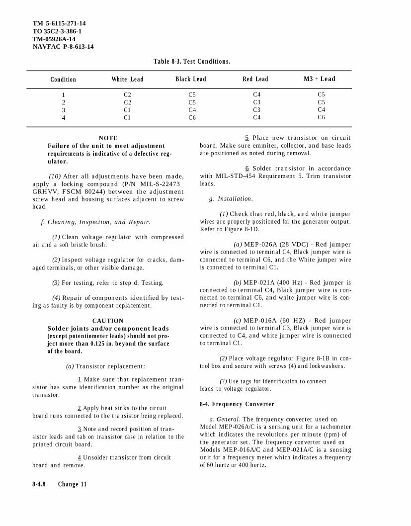
TM 5-6115-271-14TO 35C2-3-386-1TM-05926A-14NAVFAC P-8-613-14
Table 8-3. Test Conditions.
Condition White Lead Black Lead Red Lead M3 + Lead
1 C2 C5 C4 C52 C2 C5 C3 C53 C1 C4 C3 C44 C1 C6 C4 C6
NOTEFailure of the unit to meet adjustmentrequirements is indicative of a defective reg-ulator.
(10) After all adjustments have been made,apply a locking compound (P/N MIL-S-22473GRHVV, FSCM 80244) between the adjustmentscrew head and housing surfaces adjacent to screwhead.
f. Cleaning, Inspection, and Repair.
(1) Clean voltage regulator with compressedair and a soft bristle brush.
(2) Inspect voltage regulator for cracks, dam-aged terminals, or other visible damage.
(3) For testing, refer to step d. Testing.
(4) Repair of components identified by test-ing as faulty is by component replacement.
CAUTIONSolder joints and/or component leads(except potentiometer leads) should not pro-ject more than 0.125 in. beyond the surfaceof the board.
(a) Transistor replacement:
1 Make sure that replacement tran-sistor has same identification number as the originaltransistor.
2 Apply heat sinks to the circuitboard runs connected to the transistor being replaced.
3 Note and record position of tran-sistor leads and tab on transistor case in relation to theprinted circuit board.
4 Unsolder transistor from circuitboard and remove.
8-4.8 Change 11
5 Place new transistor on circuitboard. Make sure emmiter, collector, and base leadsare positioned as noted during removal.
6 Solder transistor in accordancewith MIL-STD-454 Requirement 5. Trim transistorleads.
g. Installation.
(1) Check that red, black, and white jumperwires are properly positioned for the generator output.Refer to Figure 8-1D.
(a) MEP-026A (28 VDC) - Red jumperwire is connected to terminal C4, Black jumper wire isconnected to terminal C6, and the White jumper wireis connected to terminal C1.
(b) MEP-021A (400 Hz) - Red jumper isconnected to terminal C4, Black jumper wire is con-nected to terminal C6, and white jumper wire is con-nected to terminal C1.
(c) MEP-016A (60 HZ) - Red jumperwire is connected to terminal C3, Black jumper wire isconnected to C4, and white jumper wire is connectedto terminal C1.
(2) Place voltage regulator Figure 8-1B in con-trol box and secure with screws (4) and lockwashers.
(3) Use tags for identification to connectleads to voltage regulator.
8-4. Frequency Converter
a. General. The frequency converter used onModel MEP-026A/C is a sensing unit for a tachometerwhich indicates the revolutions per minute (rpm) ofthe generator set. The frequency converter used onModels MEP-016A/C and MEP-021A/C is a sensingunit for a frequency meter which indicates a frequencyof 60 hertz or 400 hertz.

TM 5-6115-271-14TO 35C2-3-386- 1
TM-05926A-14NAVFAC P-8-613-14
b. Test. voltage will normally be 120 volts AC for 60 and 400Hz sets and 30 volts AC for 28 volt DC sets.
(1) Stop the generator set and disconnecteither the positive or negative lead from the frequency (3) Observing polarity, with a multimeterconverter to the frequency meter. measure DC micro ampere current output on + and
– terminal of the frequency converter. This DC(2) Start the generator set and measure input micro ampere current should be within the 0 to 200
voltage across terminals L-L with a multimeter. This micro ampere range, and at 120 volts 60 Hz operation,will be close to 100 micro amperes.
Change 11 8-4.9

TM 5-6115-271-14TO 35C2-3-386-1TM-05926A-14NAVFAC P-8-613-14
8-4.10
Figure 8-2. Frequency converter, removal and installation.

TM 5-6115-271-14TO 35C2-3-386-1
TM-05926A-14NAVFAC P-8-613-14
Figure 8-3. Output selector switch and mounting bracket, removal and installation (Model MEP-021A) (Sheet 1 of 2)
8 - 5 Change 9
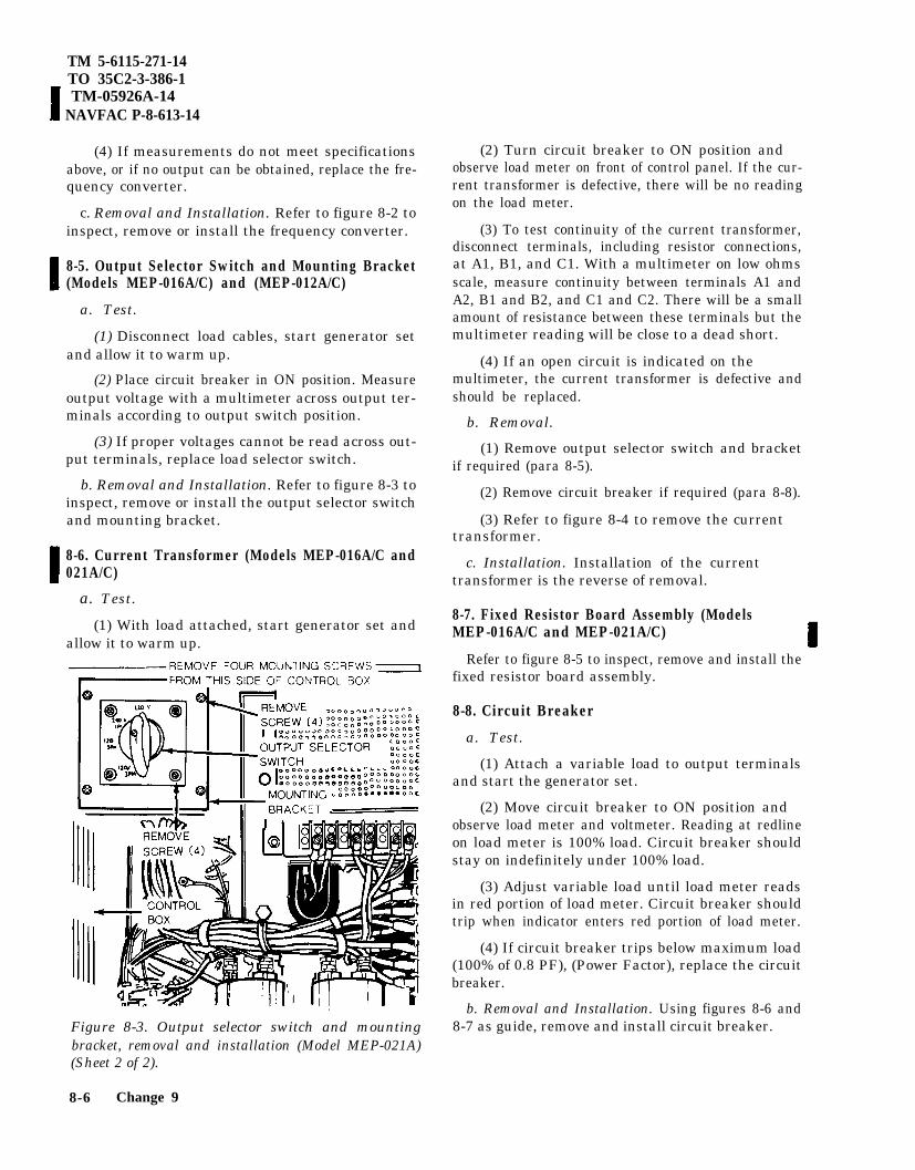
TM 5-6115-271-14TO 35C2-3-386-1 TM-05926A-14
NAVFAC P-8-613-14
(4) If measurements do not meet specificationsabove, or if no output can be obtained, replace the fre-quency converter.
c. Removal and Installation. Refer to figure 8-2 toinspect, remove or install the frequency converter.
8-5. Output Selector Switch and Mounting Bracket(Models MEP-016A/C) and (MEP-012A/C)
a. Test.
(1) Disconnect load cables, start generator setand allow it to warm up.
(2) Place circuit breaker in ON position. Measureoutput voltage with a multimeter across output ter-minals according to output switch position.
(3) If proper voltages cannot be read across out-put terminals, replace load selector switch.
b. Removal and Installation. Refer to figure 8-3 toinspect, remove or install the output selector switchand mounting bracket.
8-6. Current Transformer (Models MEP-016A/C and021A/C)
a. Test.
(1) With load attached, start generator set andallow it to warm up.
(2) Turn circuit breaker to ON position andobserve load meter on front of control panel. If the cur-rent transformer is defective, there will be no readingon the load meter.
(3) To test continuity of the current transformer,disconnect terminals, including resistor connections,at A1, B1, and C1. With a multimeter on low ohmsscale, measure continuity between terminals A1 andA2, B1 and B2, and C1 and C2. There will be a smallamount of resistance between these terminals but themultimeter reading will be close to a dead short.
(4) If an open circuit is indicated on themultimeter, the current transformer is defective andshould be replaced.
b. Removal.
(1) Remove output selector switch and bracketif required (para 8-5).
(2) Remove circuit breaker if required (para 8-8).
(3) Refer to figure 8-4 to remove the currenttransformer.
c. Installation. Installation of the currenttransformer is the reverse of removal.
8-7. Fixed Resistor Board Assembly (ModelsMEP-016A/C and MEP-021A/C)
Refer to figure 8-5 to inspect, remove and install thefixed resistor board assembly.
8-8. Circuit Breaker
a. Test.
(1) Attach a variable load to output terminalsand start the generator set.
(2) Move circuit breaker to ON position andobserve load meter and voltmeter. Reading at redlineon load meter is 100% load. Circuit breaker shouldstay on indefinitely under 100% load.
(3) Adjust variable load until load meter readsin red portion of load meter. Circuit breaker shouldtrip when indicator enters red portion of load meter.
(4) If circuit breaker trips below maximum load(100% of 0.8 PF), (Power Factor), replace the circuitbreaker.
Figure 8-3. Output selector switch and mountingbracket, removal and installation (Model MEP-021A)(Sheet 2 of 2).
8-6 Change 9
b. Removal and Installation. Using figures 8-6 and8-7 as guide, remove and install circuit breaker.

TM 5-6115-271-14TO 35C2-3-386-1
TM-05926A-14NAVFAC P-8-613-14
Figure 8-4. Current transformer, removal and installation (Models MEP-016A and MEP-021A).
Change 9 8-7

TM 5-6115-271-14TO 35C2-3-386-1TM-05926A-14NAVFAC P-8-613-14
Figure 8-5. Fixed resistor board assembly, removal andinstallation (Models MEP-016A and MEP-021A).
8 - 8

TM 5-6115-271-14TO 35C2–3-386-1
Figure 8-6. Circuit breaker, removal and installation (Model MEP-026A).
8–9

TM 5-6115-271-14TO 35C2–3-386-1
Figure 8-7. Circuit breaker, removal and installation (Model MEP-021A).
8 - 1 0

TM 5-6115-271-14TO 35C2-3-386-1
TM-05926A-14NAVFAC P-8-613-14
CHAPTER 9
MAINTENANCE OF THE HEAT SINK ASSEMBLY
9-1. General
The heat sink assembly is made up of the followingcomponents: Heat sink, LH; Rectifier, LH; Heat sink,RH; and Rectifier, RH.
9-2. Diode Rectifier and Terminal Block
Refer to figure 9-1 to inspect, remove and install thediode rectifier and terminal block.
9-3. Heat Sink (Model MEP-026A, MEP-026C)
a. Right Side Heat Sink.
(1) Removal.
(a)
(b)
(c)
(d)4-24).
(e) (a)heat sink.
Remove circuit breaker (para 8-8).
Remove suppression capacitors (para 4-13).
Remove external shunt (para 4-24).
Remove bussbars and load terminals (para
Refer to figure 9-2 and remove the right side
(2) Installation.
(a) Refer to figure 9-2 and install the right sideheat sink.
(b)4-24).
(c)
(d)
(e)
Replace bussbars and load terminals (para
Install external shunt (para 4-24).
Install suppression capacitors (para 4-13).
Replace circuit breaker (para 8-8).
b. Left Side Heat Sink.
(1) Removal.
(a) Remove and inspect the frequency converter(para 8-4).
(b) Refer to figure 9-3 to remove the left sideheat sink.
(2) Installation.
sink.
(b)
Refer to figure 9-3 to install the left side heat
Install the frequency converter (para 8-4).
9 - 1
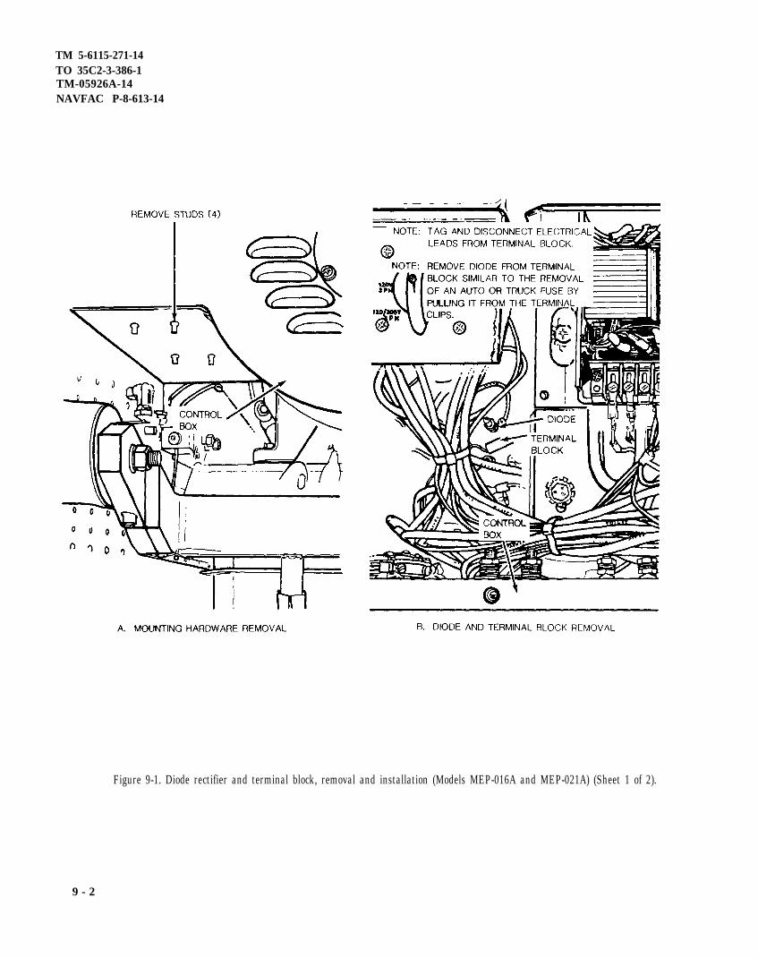
TM 5-6115-271-14TO 35C2-3-386-1TM-05926A-14NAVFAC P-8-613-14
Figure 9-1. Diode rectifier and terminal block, removal and installation (Models MEP-016A and MEP-021A) (Sheet 1 of 2).
9 - 2

TM 5-6115-271-14TO 35C2-3-386-l
Figure 9-1. Diode rectifier and terminal block, removal andinstallation (Model MEP-026A) (Sheet 2 of 2).
9-3/( 9-4 Blank)


TM 5-6115-271-14TO 35C2-3-386-1
Figure 9-2. Right side heat sink, removal and installation (Model MEP-026A).
9 - 5

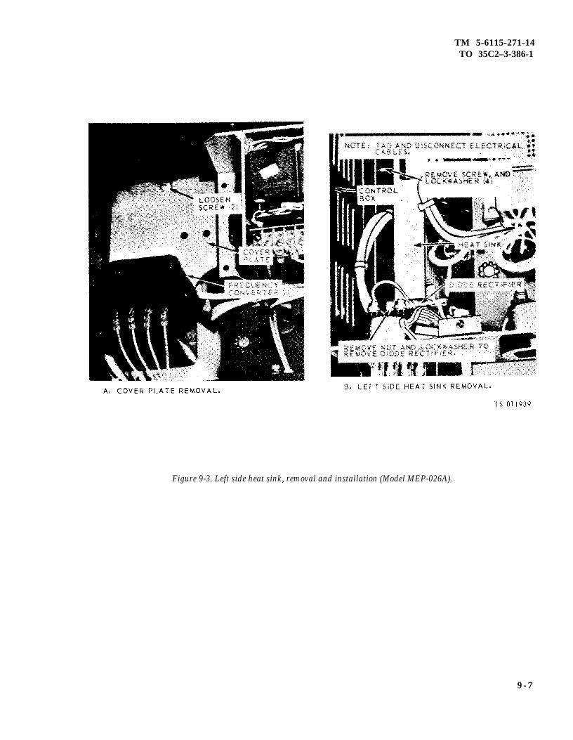
TM 5-6115-271-14TO 35C2–3-386-1
Figure 9-3. Left side heat sink, removal and installation (Model MEP-026A).
9 - 7


TM 5-6115-271-14TO 35C2-3-386-1
TM-05926A-14NAVFAC P-8-613-14
CHAPTER 10
MAINTENANCE OF THE GENERATOR
10-1. General
Repair of the generator is limited to the inspection andreplacement of faulty parts. The generators on eachof the models covered by this manual are nearly iden-tical in outward appearance. Test procedures aresimilar except for the output as prescribed. Figures10-1, 10-2 and 10-3 are included here as an aid tomaintenance personnel in troubleshooting and repair-ing the generator sets.
10-2. Generator Maintenance
a. General. These maintenance instructions applyto the generator after it has been removed from thegenerator set. For correct procedures for removingthe generator from the generator set, refer to figure6-1.
b. Model MEP-021A, MEP-021C.
(1) Removal.
(a) Remove the control box (fig. 6-3).
(b) Refer to figure 6-1 and remove thegenerator.
(2) Disassembly and reassembly. Refer to figure10-4 to disassemble and reassemble the generator.
(3) Testing.
(a) Start generator set and allow it to warm up.
(b) Observe the voltmeter on the front of thecontrol box. If exciter, rotor, or stator is defective,there will be no voltage reading on the set voltmeter.
(c) Manually flash the field windings asprescribed in paragraph 4-20e(2). If stator and rotorare good, voltage will appear and hold on the setvoltmeter.
(d) If voltage comes up, proceed withgenerator operation. If not, stop the engine and checkcontinuity of exciter stator by loosening terminal 20or 21 on the voltage regulator terminal board andmeasure across the exciter stator leads with amultimeter, for an open or short circuit. If bad, thenreplace the stator assembly.
(e) Remove generator from generator set (A,fig. 6-1), sheet 1 of 2, and remove the rotor assembly(B, fig. 6-l), sheet 2 of 2, from the stator assembly.Remove diodes from the exciter rotor (17, fig. 10-4)and test with a multimeter. Replace any bad diodes.If diodes are good, replace the rotor assembly.
(f) Reassemble generator set and repeat steps(a) and (b).
(4) Installation.
(a) Refer to figure 6-1 and install thegenerator.
(b) Install the control box (fig. 6-3).
c. Models MEP-016A, MEP-016C and MEP-026A,MEP-026C
(1) Removal.
(a) Remove the control box (fig. 6-3).
(b) Refer to figure 6-1 and remove thegenerator.
(2) Disassembly and reassembly. Refer to figure10-5 to disassemble and reassemble the generator.
(3) Testing.
(a) Start generator set and allow it to warm up.
(b) Observe the voltmeter on the front of thecontrol box. If exciter, rotor, or stator is defective,there will be no voltage reading on the set voltmeter.
(c) Manually flash the field windings asprescribed in paragraph 4-20e(2). If stator and rotorare good, voltage will appear and hold on the setvoltmeter.
(d) If voltage comes up, proceed withgenerator operation. If not, stop the engine and checkcontinuity of exciter stator by loosening terminal 20or 21 on the voltage regulator terminal board andmeasure across the exciter stator leads with amultimeter for an open or short circuit. If bad, thenreplace the stator assembly.
(e) Remove generator from generator set(A, fig. 6-1 sheet 1 of 2), and remove the rotorassembly (B, fig. 6-1 sheet 2 of 2) from the statorassembly. Remove diodes from the exciter rotor(20, fig. 10-5) and test with a multimeter for
Change 9 10-1

TM 5-6115-271-14TO 35C2-3-386-1TM-05926A-14NAVFAC P-8-613-14
resistance. Replace any bad diodes. If diodes are good, (4) Installation.replace the rotor assembly.
(a) Refer to figure 6-1 and install the(f) Reassemble generator set and repeat steps generator.
(a) and (b).(b) Install the control box (fig. 6-3).
10-2 Change 9

TM 5-6115-271-14TO 35C2-3-386-1
TM 05926A-14NAVFAC P-8-613-14
Figure 10-1. Generator schematic diagram (Model MEP-016A).
Change 6 10-3

TM 5-6115-271-14TO 35C2-3-386-1TM 05926A-14NAVFAC P-8-613-14
10-4
Figure 10-2 . Generator schematic d iagram (Model MEP-021A) .

T M 5 - 6 1 1 5 - 2 7 1 - 1 4T O 3 5 C 2 - 3 - 3 8 6 - 1
TM-05926A-14
Figure 10-3. Generator shcematic diagram (Model MEP-026A).
10-5

Figure 10-3A.
TM 5-6115-271-14TO 35C2-3-386-1TM-05926A-14
1 0 - 6

T M 5 - 6 1 1 5 - 2 7 1 - 1 4TO 35C2-3-386-1
TM-05926A-14
Figure 10-4. Generator, exploded view (Model MEP-021A).
10-7

TM 5-6115-271-14TO 35C2-3-386-1TM-05926A-14
Figure 10-5. Generator, exploded view (Models MEP-026A and MEP-016A).
10-8

TM 5-611-271-14TO 35C2-3-386-1
TM 05926A-14
APPENDIX A NAVFAC P-8-613-14
REFERENCES
This appendix contains a list of reference manualsthat may be used in conjunction with this TM inthe operation and maintenance of the 3 KW DODGenerator. Those manuals not coded are applicable
A-1. Fire Protection
TB 5-4200-200-10 (A)
A-2. Lubrication
C9100-IL (A)
LO 5-2805-203-12 (A, MC)
T.O. 35C2-3-1-426 WC-3-1-1 (F)
TB 703-1 (A)
A-3. Painting
AR 740-1 (A)
TM 43-0139 (A)
T.O. 35-1-3 (F)
MCO 4750.3B
NAVMC 2666
A-4. Radio Suppression
TM 11-483 (A)
MIL-STD-461 (F,A,MC)
MIL-STD-633C (F,MC)
A-5. Maintenance
TM 5-2805-203-14 (A)TO 38G2-90-1 (F)TM 03522-15( MC)
for use by all services. The manuals are coded(A), for Army use; (F), for Air Force use; and(MC), for Marine Corps use.
Hand Portable Fire Extinguishers Approved forArmy Use
Identification List for Fuels, Lubricants, Oils andWaxes
Engine, Gasoline: 6 HP; Military Standard Models4A032-1, 4A032-2, 4A032-3 and 4A032-4
Preventive Maintenance Workcards
Specification List of Standard Liquid Fuels,Lubricants, Preservatives, and Related ProductsAuthorized for Use by U.S. Army
Color, Marking, and Preparation of Equipment forShipment
Painting Instructions for Field Use.
Painting and Marking of USAF Aerospace GroundEquipment
Painting, Camouflage Pattern Painting, RegistrationMarking and Identification Requirements forMarine Corps Tactical Equipment
Marine Corps Guide for Camouflage Paint Patterns
Radio Interference Suppression
Radio Interference Suppression
Mobile Electric Power Engine Generator StandardFamily Characteristics Data Sheet
Operator, Organizational, DS, and GS MaintenanceManual for Engine, Gasoline, 6 HP; MilitaryStandard Models 4A032-1, 4A032-2,4A032-3, and 4A032-4.
A-1

TO 35C2-3-386-1TM 05926A-14NAVFAC P-8-613-14
TM 5-6115-271-14
A-5. Maintenance (Continued)
TM 5-764 (A,MC)
DA PAM 738-750 (A)
MCO P4790.1 (MC)
MCO P4790.2 (MC)
MCO P4790.5 (MC)
AFM 66-1 (F)
TM 5-2805-203-24P (A)
T.O. 38G2-90-14 (F)
SL-4-03522B (MC)
T.O. 35C2-3-426 WC 3-1-1 (F)
TM 5-6115-271-24P (A)T.O. 35C2-3-386-4 (F)SL-4-059-26A
T.O. 35C2-3-1-426 (F)
T.O. 00-51 (F)
T.O. 34Y19-1-111 (F)
A-6. Shipment and Storage
TB 740-97-2 (A, MC)
T.O. 35-1-4 (F)
T.O. 38-1-5 (F)
A-7. Operation
TM 5-766 (A, MC)
TB MED 251 (A)
FM 21-11
Electric Motor and Generator Repair
The Army Maintenance Management System(TAMMS)
MIMMS Introduction Manual
Field Procedures Manual
Field Users Manual
Maintenance Management
Organizational, Direct and General SupportMaintenance Repair Parts and Special ToolLists: Engine, Gasoline, 6 HP; Military StandardModels 4A032-1, 4A032-2 and 4A032-3
Preventive Maintenance Workcards
Organizational, Direct and General Support RepairParts and Special Tool Lists for Generator Set,GED, 3 KW, Military Design (less engine) AC,400 Hz, DOD Model MEP-021A, MEP-021C;AC, 60 Hz, DOD Model MEP-016A; MEP-016C;DC, 28 V, DOD Model MEP-026A, MEP-026C.
Maintenance Manual
Air Force Technical Order System
Electric Motor and Generator Repair
Preservation of USAMECOM MechanicalEquipment for Shipment and Storage
Processing and Inspection of Aerospace GroundEquipment
Processing and Inspection of Nonmounted, Non-Aircraft Gasoline and Diesel Engines for Storageand Shipment
Electric Power Generation in the Field
Noise and Conservation of Hearing
First Aid for Soldiers
A - 2

TM 5-6115-271-14TO 35C2-3-386-1TM 05926A-14NAVFAC P-8-613-14
A-8. Demolition of Equipment
TM 750-244-3 (A) Procedures for Destruction of Equipment to PreventEnemy Use (Mobility Equipment Command)
A-9. Specifications
DA PAM 25-30 Consolidated Index of Army Publications andForms
Change 10 A-3/(A-4 blank)


TM 5-6115-271-14TO 35C2-3-386-1
TM-05926A-14NAVFAC P-8-613-14
APPENDIX BBASIC ISSUE ITEMS LIST AND ITEMS TROOP INSTALLED OR AUTHORIZED
B-1. Scope(A) This appendix lists items required by the
operator for operation of the generator set.
B-2. GeneralThis list is divided into the following sections:
a. Basic Issue Items List – Section II. These are theminimum essential items required to place the generator setin operation, to operate it and to perform emergencyrepairs. Although shipped separately packaged, BII must bewith the generator set during operation and whenever it istransferred between property accounts. This manual is yourauthority to request/requisition BII, based on TOE/MTOEauthorization of the end item.
b. Items Troop Installed or Authorized List -Section III. A list of items in alphabetical sequence, whichat the discretion of the unit commander may accompany thegenerator set. These items are NOT subject to turn-in withthe generator set.
B-3. Explanation of ColumnsThe following provides an explanation of columns in thetabular list of items Troop Installed or Authorized, SectionIII.
a. National/NATO Stock Numbers. This columnindicates the National/NATO stock numbers assigned to theitem and will be used for requisitioning purposes.
b. Description. This column indicates the Federalitem name and any additional description of the itemrequired.
c. Unit of Measure (U/M). A two-characteralphabetical abbreviation indicating the amount or quantityof the item upon which the allowances are based, e.g., ft, ea,pr, etc.
d. Quantiy Authorized. This column indicates thequantity of the item authorized to be used with theequipment.
Section II. BASIC ISSUE ITEMS (BII) LIST
National/NATOStock Description Qty
Number Part Number & FSCM Usable on Code U/M auth
4210-00-555-8837 Extinguisher, Fire EA 15975-00-878-3791 Rod Assembly, Ground EA 15120-01-013-1676 Slide Hammer, Ground Rod EA 1
Manual, Technical, TM 5-6115-271-14 EA 1
Change 11 B-1

TM 5-6115-271-14TO 35C2-3-386-1TM-05926A-14NAVFAC P-8-613-14
Section III. ITEMS TROOP INSTALLED OR AUTHORIZED LIST
National/NATOStock Description Qty
Number Part Number & FSCM Usable on Code U/M auth
2910-00-066-1235 ADAPTER ASSEMBLY, fuel . . . . . . . . . . . . . . . . . . . . . . . . . . . . . . . .EA 17520-00-559-9618 CASE, maintenance and operation manuals . . . . . . . . . . . . . . . . . . . . . . EA 16115-00-960-2703 COVER, canvas . . . . . . . . . . . . . . . . . . . . . . . . . . . . . . . . . . . . . . . . . . . .EA 14720-00-274-9480 HOSE ASSEMBLY, Fuel . . . . . . . . . . . . . . . . . . . . . . . . . . . . . . . . . . . .EA 12920-00-075-1710 STARTER KIT, ASSEMBLY, electrical 13208E5819(97403),
consisting of the following items. . . . . . . . . . . . . . . . . . . . . . . . . . EA 1Complete Kit should be requisitioned for installing an electricalstarter for first time. When components need replacing, requisi-tion the component needed as follows:
NOTE
Starter Kit Assembly for the following generator sets is authorized for general use.Requisitions for this kit must be accomplished by make and model and serialnumber of the end item generator set.
NSN Hertz DOD Model6115-00-017-8237 3 KW60 MEP-016A, MEP-016C6115-00-017-8238 3 KW 400 MEP-021A, MEP-021C6115-00-017-8239 3 KW DC MEP-026A, MEP-026C
6115-00-961-1103 BRACKET . . . . . . . . . . . . . . . . . . . . . . . . . . . . . . . . . . . . . . . . . . . . . . ..EA 113219E0830 (97403)
5935-00-814-7432 CONNECTOR, RECEPTACLE . . . . . . . . . . . . . . . . . . . . . . . . . . . . . .EA 1MS75058-1 (96906)
B-2 Change 11

TM 5-6115-271-14TO 35C2-3-386-1
TM-05926A-14NAVFAC P-8-613-14
Section III. ITEMS TROOP INSTALLED OR AUTHORIZED LIST-Continued
National/NATOStock Description Qty
Number Part Number & FSCM Usable on Code U/M auth
2920-00-882-3401
5310-00-761-6882
5930-00-655-1522
5305-00-225-3839
5305-00-253-5615
5305-00-225-8499
5305-00-036-6982
5940-40-204-8961
5310-00-889-2528
6145-00-195-5602
6145-00-578-7517
5935-00-322-8959
MOTOR, STARTER . . . . . . . . . . . . . . . . . . . . . . . . . . . . . . . . . . . . . . . .EA13213E3285 (97403)
NAMEPLATE, STARTER . . . . . . . . . . . . . . . . . . . . . . . . . . . . . . . . . .EA13208E5818 (97403)
NUT, PLAIN receptacle mug . . . . . . . . . . . . . . . . . . . . . . . . . . . . . . . .EAMS51967-2 (96906)
SWITCH, TOGGLE . . . . . . . . . . . . . . . . . . . . . . . . . . . . . . . . . . . . . . . .EAMS35058-30 (96906)
SCREW CAP, HEX HD . . . . . . . . . . . . . . . . . . . . . . . . . . . . . . . . . . . .EAMS90725-41 (96906)
SCREW, CAP: receptacle mug . . . . . . . . . . . . . . . . . . . . . . . . . . . . . . .EAMS90725-8 (96906)
SCREW, DRIVE . . . . . . . . . . . . . . . . . . . . . . . . . . . . . . . . . . . . . . . . . .EAMS21318-21 (96906)
SCREW & EXTERNAL TOOTH LOCKWASHER ASSY5/16-18 UNC-2A x 1LG, STL CAD PLTD SAE-J489 . . . . . . . . . . . . EASCREW & LOCKWASHER, EXT TOOTHASSY ., 1/4-20UNC-2AX 3/4 LG, HEX HD TRIMMED, S LOT CADORZNPLTD SAE-J489 . . . .TERMINAL LUG . . .MS25036-24 (96906)
TERMINAL LUG . . .MS25036-25 (96906)
TERMINAL LUG . . .MS25036-6 (96906)
TERMINAL LUG . . .MS25036-8 (96906)
TERMINAL LUG . . .MS25036-10 (96906)
. . . . . . . . . . . . . . . . . . . . . . . . . . . . . . . . . . . . . . . EA
. . . . . . . . . . . . . . . . . . . . . . . . . . . . . . . . . . . . . . . EA
. . . . . . . . . . . . . . . . . . . . . . . . . . . . . . . . . . . . . . . EA
. . . . . . . . . . . . . . . . . . . . . . . . . . . . . . . . . . . . . . . EA
. . . . . . . . . . . . . . . . . . . . . . . . . . . . . . . . . . . . . . . EA
. . . . . . . . . . . . . . . . . . . . . . . . . . . . . . . . . . . . . . . EA
WASHER, LOCK: Receptacle mtg . . . . . . . . . . . . . . . . . . . . . . . . . . EAMS45904-68 (96906)
WIRE, ELEC #4 . . . . . . . . . . . . . . . . . . . . . . . . . . . . . . . . . . . . . . . . . FTMS5086/2-4-9 (81349)
WIRE, ELEC #16 . . . . . . . . . . . . . . . . . . . . . . . . . . . . . . . . . . . . . . . . . FTM5086/1-16-9 (81349)
ADAPTER CONNECTOR . . . . . . . . . . . . . . . . . . . . . . . . . . . . . . EA
1
1
4
1
1
4
2
2
11
1
2
1
1
4
5
5
1
Change 11 B-3/(B-4 blank)


TM 5-6115-271-14TO 35C2-3-386-1
TM-05926A-14NAVFAC P-8-613-14
APPENDIX C
MAINTENANCE ALLOCATION CHART
(ARMY ONLY)
Section I. INTRODUCTION
C-1. Generala. This section provides a general explanation of
all maintenance and repair function authorized atvarious maintenance levels.
b. Section II designates overall responsibility forthe performance of maintenance functions on the iden-tified end item or component and the work measure-ment time required to perform the functions by thedesignated maintenance level. The implementation ofthe maintenance functions upon the end item or com-ponent will be consistent with the assignedmaintenance functions.
c. Section III lists the tools and test equipment re-quired for each maintenance function as referencedfrom Section II.
C-2. Explanation of Columns in Section IIa. Column (1), Group Number. Column 1 lists
group numbers to identify related components,assemblies, subassemblies, and modules with theirnext higher assembly. The applicable groups are listedin the MAC in disassembly sequence beginning withthe first group removed.
b. Column (2), Component/Assembly. This col-umn contains the noun names of components,assemblies, subassemblies and modules for whichmaintenance is authorized:
c. Column (3), Maintenance Functions. This col-umn lists the functions to be performed on the itemlisted in Column 2. The maintenance functions aredefined as follows:
(1) Inspect. To determine serviceability of anitem by comparing its physical, mechanical, and/orelectrical characteristics with established standardsthrough examination.
(2) Test, To verify serviceability and detect in-cipient failure by measuring the mechanical or elec-trical characteristics of an item and comparing thosecharacteristics with prescribed standards.
(3) Service. Operations required periodically tokeep an item in proper operating condition, i.e., toclean (decontaminate), to preserve, to drain, to paint,or to replenish fuel, lubricants, hydraulic fluids, orcompressed air supplies.
(4) Adjust. To maintain within prescribed limits,by bringing into proper or exact position, or by settingthe operating characteristics to specified parameters.
(5) Align. To adjust specified variable elementsof an item to bring about optimum or desiredperformance.
(6) Calibrate. To determine and cause correc-tions to be made or to be adjusted on instruments ortest measuring and diagnostic equipments used inprecision measurement. Consists of comparison oftwo instruments, one of which is a certified standardof known accuracy, to detect and adjust anydiscrepancy in the accuracy of the instrument beingcompared.
(7) Install. The act of emplacing, seating, or fix-ing into position an item, part, or module (componentor assembly) in a manner to allow the proper function-ing of an equipment or system.
(8) Replace. The act of substituting a serviceablelike type part, subassembly, or module (component orassembly) for an unserviceable counterpart.
(9) Repair. The application of maintenance ser-vices (inspect, test, service, adjust, align, calibrate, orreplace) or other maintenance actions (welding, grind-ing, riveting, straightening, facing, remachining orresurfacing) to restore serviceability to an item by cor-recting specific damage, fault, malfunction, or failurein a part, subassembly, module (component orassembly), an end item, or system.
(10) Overhaul. That maintenance effort (ser-vice/action) necessary to restore an item to a complete-ly serviceable/operational condition as prescribed bymaintenance standards (i.e., DMWR) in appropriatetechnical publications. Overhaul is normally thehighest degree of maintenance performed by the Ar-my. Overhaul does not normally return an item to likenew condition.
C - 1

Section II.
TM 5-6115-271-14TO 35C2-3-386-1TM-05926A-14NAVFAC P-8-613-14
(11) Rebuild. Consists of those services/actionsnecessary for the restoration of unserviceable equip-ment to a like new condition in accordance withoriginal manufacturing standards. Rebuild is thehighest degree of material maintenance applied toArmy equipment. The rebuild operation includes theact of returning to zero those age measurements(hours/miles, etc.) considered in classifying Armyequipments/components.
d. Column (4), Maintenance Category. This columnis made up of subcolumns for each category ofmaintenance. Work time figures are listed in thesesub-columns for the lowest level of maintenanceauthorized to perform the function listed in column 3.These figures indicate the average active timerequired to perform the maintenance function at theindicated category of maintenance under typical fieldoperating conditions.
e. Column (5), Tools and Equipment. This columnis provided for referencing by code, the common toolsets (not individual tools), special tools, test and sup-port equipment required to perform the designatedfunction. Refer to Section III.
(1)
GroupNumber
(4)
O
01
02
C-3. Explanation of Columns in Section III
a. Column (1), Reference Code. This column con-sists of an arabic number listed in sequence fromcolumn 5 of Section II. The number references thecommon tool sets, special tools and test equipmentrequirements.
b. Column (2), Maintenance Category. This columnshows the lowest category of maintenance authorizedto use the special tools or test equipment.
c. Column (3), Nomenclature. This column lists thename or identification of the common tool sets, specialtools or test equipment.
d. Column (4), Nationa/NATO Stock No. (NSN).This column is provided for the NSN of common toolsets, special tools and test equipment listed in thenomenclature column.
e. Column (5), Tool Number. This column lists themanufacturer’s code and part number of tools andtest equipment.
(2)
Component/Assembly
FRAME ASSEMBLYFrame, Upper . . . . . . . . . . . . . . . .
Shock Mounts . . . . . . . . . .
Ground Stud and Strap . . . . . . . . . .
CONTROL BOX ASSEMBLYControl Box . . . . . . . . . . . . . . . . . . . .
Resistor, Variable . . . . . . . . . . . . . . .
Switches . . . . . . . . . . . . . . . . . . . . .
(3)
MaintenanceFunction
InspectReplaceRepair
InspectReplace
InspectReplace
InspectReplaceRepair
InspectTestReplace
InspectTestReplace
C
**0.1
0.1
0.1
0.1
Maintenance Category
0.5
1.0
0.2
0.10.10.2
0.10.10.5
F
1.0
0.80.6
H D
(5)
Tools andEquipment
1
11
2
3,2
*Subcolumns are as follows C-Operator/crew; O-Organizational; F-Direct support; H-General support; D-Depot.**Indicates Worktime (Manhours) Required
C-2 Change 9

TM 5-6115-271-14TO 35C2-3-386-1
TM-05926A-14NAVFAC P-8-613-14
Section II. MAINTENANCE ALLOCATION CHART-Continued
(1) (2) (3) (4) (5)Maintenance Category
Group Component/Assembly Maintenance Tools andNumber Function C O F H D Equipment
Meters Inspect 0.1Test 0.1 3Replace 0.3
Meter, Frequency Transducer Inspect 0.1Test 0.1 3Replace 0.3
Holder, Fuse . . . . . . . . . . . . . . . . Inspect 0.1Replace 0.2
Circuit Breaker . . . . . . . . . . . . . . . . . Inspect 0.1Test 0.1 3Replace 0.1
Voltage Regulator . . . . . . . . . . . . . . . Inspect 0.2Test 0.2 3Replace 0.2
Transformer, Current . . . . Inspect 0.1Test 0.1 3Replace 0.5
Receptacle, Convenience Inspect 0.1Replace 1.0
Terminal, Load/Insulator Inspect 0.1Replace 0.5
Capacitor, RFI Suppression Inspect 0.2Test 0.2 3Replace 0.5
03 HEAT SINK ASSEMBLYHeat Sink . . . . . . . . . . . . . . . . . . . . . . . Inspect 0.2
Replace 1.0
Rectifier . . . . . . . . . . . . . . . . . . . . . Inspect 0.2Test 0.2 2Replace 0.5
04 GENERATOR ASSEMBLYGenerator Assembly . . . . . . . . . . . . . Inspect 0.5
Test 0.5 2,3Replace 2.0Overhaul 2.0
Rotor Generator . . . . . . . . . . . . . Inspect 0.2Test 0.5 3Replace 2.0Repair 2.0
Rotor Assembly . . . . . . . . . . . . . . . . Inspect 0.2Test 0.5 3Replace 2.0Repair 2.0
❵ Subcolumns are as follows C-Operator/crew, O-Organizational ;F-Direct support; H-General support; D-Depot. Idicates Worktime (Manhours) Required C-3
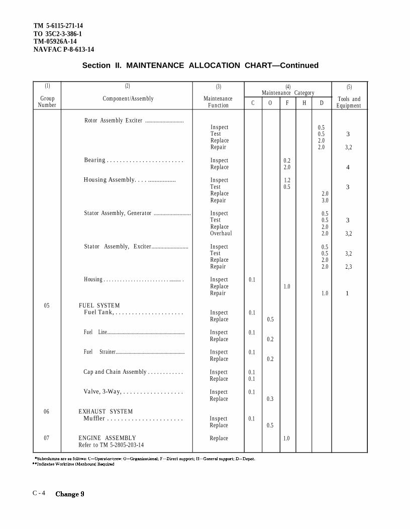
TM 5-6115-271-14TO 35C2-3-386-1TM-05926A-14NAVFAC P-8-613-14
Section II. MAINTENANCE ALLOCATION CHART—Continued
(1) (2) (3) (4) (5)Maintenance Category
Group Component/Assembly Maintenance Tools andNumber Function C O F H D Equipment
Rotor Assembly Exciter ...........................Inspect 0.5Test 0.5 3Replace 2.0Repair 2.0 3,2
Bearing . . . . . . . . . . . . . . . . . . . . . . . . Inspect 0.2Replace 2.0 4
Housing Assembly. . . . ................. Inspect 1.2Test 0.5 3Replace 2.0Repair 3.0
Stator Assembly, Generator .......................... Inspect 0.5Test 0.5 3Replace 2.0Overhaul 2.0 3,2
Stator Assembly, Exciter......................... Inspect 0.5Test 0.5 3,2Replace 2.0Repair 2.0 2,3
Housing . . . . . . . . . . . . . . . . . . . . . . . . ......... . Inspect 0.1Replace 1.0Repair 1.0 1
05 FUEL SYSTEMFuel Tank, . . . . . . . . . . . . . . . . . . . . . Inspect 0.1
Replace 0.5
Fuel Line..................................................................... Inspect 0.1Replace 0.2
Fuel Strainer............................................................. Inspect 0.1Replace 0.2
Cap and Chain Assembly . . . . . . . . . . . . Inspect 0.1Replace 0.1
Valve, 3-Way, . . . . . . . . . . . . . . . . . . Inspect 0.1Replace 0.3
06 EXHAUST SYSTEMMuffler . . . . . . . . . . . . . . . . . . . . . . Inspect 0.1
Replace 0.5
07 ENGINE ASSEMBLY Replace 1.0Refer to TM 5-2805-203-14
C - 4
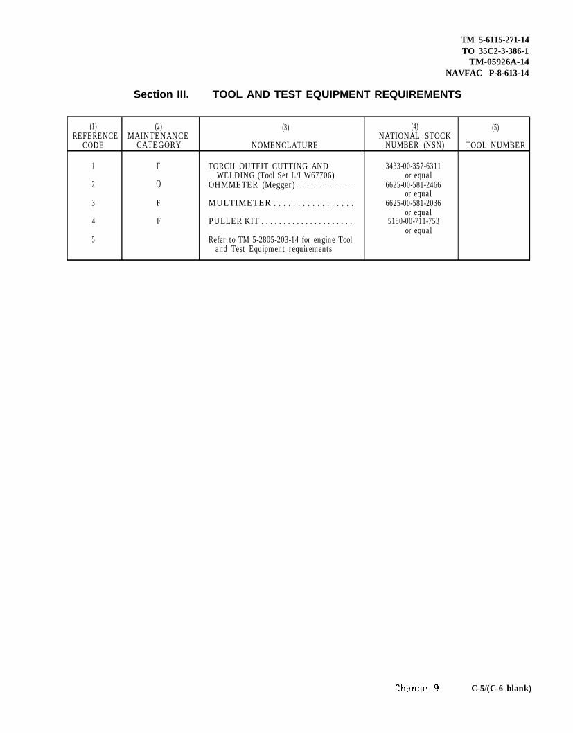
TM 5-6115-271-14TO 35C2-3-386-1
TM-05926A-14NAVFAC P-8-613-14
Section III. TOOL AND TEST EQUIPMENT REQUIREMENTS
(1) (2) (3) (4) (5)REFERENCE MAINTENANCE NATIONAL STOCK
CODE CATEGORY NOMENCLATURE NUMBER (NSN) TOOL NUMBER
1 F TORCH OUTFIT CUTTING AND 3433-00-357-6311WELDING (Tool Set L/I W67706) or equal
2 O OHMMETER (Megger) 6625-00-581-2466or equal
3 F MULTIMETER . . . . . . . . . . . . . . . . . 6625-00-581-2036
4 For equal
PULLER KIT . . . . . . . . . . . . . . . . . . . . . 5180-00-711-753or equal
5 Refer to TM 5-2805-203-14 for engine Tooland Test Equipment requirements
C-5/(C-6 blank)


TM 5-6115-271-14TO 35C2–3-386-1
By Order of the Secretaries of the Army and the Air Force:
FRED C. WEYANDGeneral, United States Army
Official: Chied of StaffPAUL T. SMITHMajor General, United States ArmyThe Adjutant General
DAVID C. JONES, General, USAFOfficial: Chief of Staff
JAMES J. SHEPARD, Colonel, USAFDirector of Administration
Distribution:To be distributed in accordance with DA Form 12-25D, Organizational maintenance requirements for
Generator Sets, Engine Driven 3 KW 60 HZ, 3 KW 400 HZ and 3 KW D.C.


TM 5-6115-271-14 /TO 35C2-3-386-1 / TM 05926A-14 / NAVFAC P-8-613-14
Figure FO-1 Wiring diagram (Model MEP-016A) TS 011945
Change 10 FO-1

Figure FO-2. Wiring diagram (Model MEP-021A). TS 011946

Figure FO-3. Wiring diagram (Model MEP-026A).TS 011947

TM 5-6115-271-14TO 35C2-3-386-1
TM 05926A-14NAVFAC P-8-613-14
FO-3.1 Wiring Diagram (Model MEP-026A) Old RegulatorC h a n g e 9 FO-3.1

TM 5-6115-271-14TO 35C2-3-386-1
TM 05926A-14NAVFAC P-8-613-14
Figure F0-4. Wiring Diagram, Standard Voltage Regulator(FMC97403 13219E0886) TSO11947
Change 5 FO-4

TM 5-6115-271-14TO 35C2-3-386-1
TM 05926A-14NAVFAC P-8-613-14
Figure FO-5. Schematic Diagram Standard Voltage Regulator3KW, 5KW, 10KW, DC, 60Hz, 400Hz (FMC97403 13219E0887) TSO11948
Change 3 FO-5

The Metric System and EquivalentsLinear Measure
1 centimeter = 10 millimeters = .39 inch1 decimeter = 10 centimeters = 3.94 inches1 meter = 10 decimeters = 39.37 inches1 dekameter = 10 meters = 32.8 feet1 hectometer = 10 dekameters = 328.08 feet
kilometer = 10 hectometers = 3,280.8 feet
Weightscentigram = 10 milligrams = .15 graindecigram = 10 centigrams = 1.54 grainsgram = 10 decigrams = .035 ounce
1 deckagram = 10 grams = .35 ounce1 hectogram = 10 dekagrams = 3.52 ounces1 kilogram = 10 hectograms = 2.2 pounds1 quintal = 100 kilograms = 220.46 pounds1 metric ton = 10 quintals = 1.1 short tons
Liguid Measure1 centiliter = 10 milliliters = .34 fl. ounce1 deciliter = 10 centiliters = 3.38 fl. ounces
To changeinchesfeetyardsmilessquare inchessquare feetsquare yardssquare milesacrescubic feetcubic yardsfluid ouncespintsquartsgallonsouncespoundsshort tons
ApproximateTo Multiply by
centimeters 2.540meters .305meters .914kilometers 1.609square centimeters 6.451square meters .093square meters .836square kilometers 2.590square hectometers .405cubic meters .028cubic meters .765milliliters 29.573liters .473liters .946liters 3.785grams 28.349kilograms .454metric tons .907
1 liter = 10 deciliters = 33.82 fl. ounces1 dekaliter = 10 liters = 2.64 gallons1 hectoliter = 10 dekaliters = 26.42 gallons1 kiloliter = 10 hectoliters = 264.18 gallons
Square Measure1 sq. centimeter = 100 sq. millimeters = .155 sq. inch1 sq. decimeter = 100 sq. centimeters = 15.5 sq. inches1 sq. meter (centare) = 100 sq. decimeters = 10.76 sq. feet1 sq. dekameter (are) = 100 sq. meters = 1,076.4 sq. feet1 sq. hectometer (hectare) = 100 sq. dekameters = 2.47 acres1 sq. kilometer = 100 sq. hectometers = .386 sq. mile
Cubic Measure1 cu. centimeter = 1000 cu. millimeters = .06 cu. inch1 cu. decimeter = 1000 cu. centimeters = 61.02 cu. inches1 cu. meters = 1000 cu decimeters = 35.31 cu. feet
Conversion FactorsTo Changecentimetersmetersmeterskilometerssquare centimeterssquare meterssquare meterssquare kilometerssquare hectometerscubic meterscubic metersmilliliterslitersliterslitersgramskilogramsmetric tons
Toinchesfeetyardsmilessquare inchessquare feetsquare yardssquare milesacrescubic feetcubic yardsfluid ouncespintsquartsgallonsouncespoundsshort tons
Multipy by.394
3.2801.094.621.155
10.7641.196.386
2.47135.315
1.308.034
2.1131.057.264.035
2.2051.102

Related Documents