TM 5-6115-323-14 DEPARTMENT OF THE ARMY TECHNICAL MANUAL TO 35C2-3-385-1 DEPARTMENT OF THE AIR FORCE TECHNICAL ORDER TECHNICAL MANUAL OPERATOR/CREW, ORGANIZATIONAL, INTERMEDIATE (FIELD) (DIRECT SUPPORT AND GENERAL SUPPORT) AND DEPOT MAINTENANCE MANUAL GENERATOR SET, GASOLINE ENGINE DRIVEN, SKID MOUNTED, TUBULAR FRAME, 1.5 KW, SINGLE PHASE, AC, 120/240 V, 28 V DC (LESS ENGINE) DOD MODELS HERTZ NSN MEP-015A 60 6115-00-889-1446 MEP-025A DC 6115-00-017-8236 HEADQUARTERS, DEPARTMENT OF THE ARMY and AIR FORCE 1976

Welcome message from author
This document is posted to help you gain knowledge. Please leave a comment to let me know what you think about it! Share it to your friends and learn new things together.
Transcript

TM 5-6115-323-14DEPARTMENT OF THE ARMY TECHNICAL MANUAL
TO 35C2-3-385-1DEPARTMENT OF THE AIR FORCE TECHNICAL ORDER
TECHNICAL MANUAL
OPERATOR/CREW, ORGANIZATIONAL, INTERMEDIATE (FIELD)
(DIRECT SUPPORT AND GENERAL SUPPORT) AND DEPOT
MAINTENANCE MANUAL
GENERATOR SET, GASOLINE ENGINE DRIVEN, SKID MOUNTED,TUBULAR FRAME, 1.5 KW, SINGLE PHASE, AC, 120/240 V,
28 V DC (LESS ENGINE)
DOD MODELS HERTZ NSN
MEP-015A 60 6115-00-889-1446MEP-025A DC 6115-00-017-8236
HEADQUARTERS, D E P A R T M E N T O F T H E A R M Ya n d A I R F O R C E
1 9 7 6

Take particular heed
or severe burns may
Do not operate thisground.
TM 5-6115-323-14TO 35C2–3-385-1
WARNINGto specific cautions and warnings throughout this manual.
HIGH VOLTAGEis used in the operation of this equipment.
DEATHresult if personnel fail to observe safety precautions.
generator set until the ground terminal stud has been connected to a suitable
On gasoline engine driven generator sets utilizing magnetos, set magneto switch to OFF or STOPposition.
Do not attempt to change load connections when generator is running.
Before servicing any part of a generator set, make sure unit is completely de-energized.
DANGEROUS GASESare generated as a result of operating this equipment.
DEATHor severe injury may result if personnel fail to observe safety precautions.
Do not smoke, or use open flame when servicing batteries.Batteries generate explosive gas while discharging and charging.
Always maintain metal-to-metal contact when filling the fuel tank. Do not smoke or use open flamewhen filling the fuel tank. Do not attempt to fill the fuel tank when the generator is running. Do notoperate generator sets in inclosed areas unless exhaust gases are properly vented to the outside.
Exhaust discharge contains noxious and deadly fumes.
NOISE
Operation of this equipment presents a noise hazard to personnel in the area. The noise level exceedsthe allowable limits for unprotected personnel. Wear ear muffs or ear plugs which were fitted by atrained professional.
CAUTION
DAMAGEto the equipment may result if personnel fail to observe safety precautions.
If the generator set is shut-down by the operation of a safety device, do not attempt to operate theunit until the cause has been determined and eliminated.
WARNING
Dry cleaning solvent, P–D–680, used to clean parts is potentially dangerous to personnel andproperty. Avoid repeated and prolonged skin contact. Do not use near open flame or excessive heat.Flash point of solvent is 100°F.-138ºF. (38°C.-59°C.).

ARMY TM 5-6115-323-14AIR FORCE TO 35C2-3-385-1
C 10
CHANGE HEADQUARTERSDEPARTMENTS OF THE ARMY AND AIR FORCE
NO. 10 WASHINGTON, D.C., 25 September 1996
Operator/Crew, Organizational, Intermediate (Field)(Direct Support and General Support) and
Depot Maintenance Manual
GENERATOR SET, GASOLINE ENGINE DRIVEN, SKID MOUNTED,TUBULAR FRAME, 1.5 KW, SINGLE PHASE, AC, 120/240 V,
28 V DC (LESS ENGINE)
DOD MODEL HERTZ NSN
MEP-015A 60 6115-00-889-1446MEP-025A 28 V DC 6115-00-017-8236
DISTRIBUTION STATEMENT A: Approved for public release; distribution is unlimited
TM 5-6115-323-14/TO 35C2-3-385-1, 23 July 1976, is changed as follows:
1. Remove and insert pages as indicated below. New or changed text material is indicated by a vertical bar in themargin. An illustration change is indicated by a miniature pointing hand.
Remove pages Insert pages
i and ii i and ii1-1 and 1-2 1-1 and 1-2B-1 and B-2 B-1 and B-2
2. Retain this sheet in front of manual for reference purposes.


TM 5-6115-323-14TO 35C2-3-385-1
C 9CHANGE HEADQUARTERS
DEPARTMENTS OF THE ARMY AND AIR FORCENO. 9 WASHINGTON, D.C., 17 September 1991
Opcrator/Crew, Organizational, Intermediate (Field) (Direct Support and General Support)and Depot Maintenance Manual
GENERATOR SET, GASOLINE ENGINE DRIVEN, SKID MOUNTED, TUBULAR FRAME,1.5 KW, SINGLE PHASE, AC, 120/240 V, 28 V DC (LESS ENGINE)
DOD MODEL HERTZ NSN
MEP-015A 60 6115-00-889-1446MEP-025A 28 V DC 6115-00-017-8236
Approved for public release; distribution is unlimited
TM 5–6115–323–14, 23 July 1976, is changed as follows:
1. Remove and insert pages as indicated below. New or changed text material is indicated by a vertical bar inthe margin. An illustration change is indicated by a miniature pointing hand.
Remove pages Insert pages
4–13through 4-16 4–13 through 4–166-1 and 6-2 6-1 and 6-28–5 and 8-6 8–5 and 8–6
2. Retain this sheet in front of manual for reference purposes.

TM 5-6115-323-14TO 35C2-3-385-1
C9By Order of the Secretaries of the Army and Air Force:
GORDON R. SULLIVANGeneral, United States Army
Chief of Staff
Official:PATRICIA P. HICKERSON
Brigadier General, United States ArmyThe Adjutant General
MERRILL A. McPEAKGeneral USAFChief of Staff
Official:CHARLES C. McDONALD
General, USAFCommander, Air Force logistics Command
DISTRIBUTION:To be distributed in accordance with DA Form 12-25E, (qty rqr block no. 0874)

TM 5-6115-323-14TO 35C2-3-385-1
C 8CHANGE HEADQUARTERS,
DEPARTMENTS OF THE ARMY AND AIR FORCENO. 8 WASHINGTON, D.C., 24 OCTOBER 1990
Operator/Crew, Organizational, Intermediate (Field) (Direct Support and General Support)and Depot Maintenance Manual
GENERATOR SET, GASOLINE ENGINE DRIVEN, SKID MOUNTED, TUBULAR FRAME,1.5 kW, SINGLE PHASE, AC, 120/240 V, 28 V DC (LESS ENGINE)
DOD MODEL HERTZ NSN
MEP-015A 60 6115-00-889-1446MEP-025A 28V DC 6115-00-017-8236
Approved for public release; distribution is unlimited
TM 5-6115–323-14, 23 July 1976 is changed as follows:
1. Remove and insert pages as indicated below. New or changed text material is indicated by a vertical bar inthe margin. An illustration change is indicated by a miniature pointing hand.
Remove pages Insert pages
3-2.1 and 3-2.2 3-2.1 and 3-2.24-11 through 4-16 4-11 through 4-165-3 and 5-4 5-3 and 5-46-1 and 6-2 6-1 and 6-28-1 and 8-2 8-1 and 8-28-5 and 8-6 8–5 and 8-6B–1 and B-2 B–1 and B–2C-5/(C-6 blank) C-5 and C-6
2. Retain this sheet in front of manual for reference purposes.
TM 5-6115-323-14TO 35C2--3-385-l
C8 By Order of the Secretary of the Army:
CARL E. VUONOGeneral, United States Army
Chief of Staff
Official:THOMAS F. SIKORA
Brigadier General, United States ArmyThe Adjutant General
MERRILL A. McPEAKGeneral USAFChief of Staff
Official:CHARLES C. MCDONALD
General, USAFCommander, Air Force Logistics Command
DISTRIBUTION:To be distributed in accordance with DA Form 12–25E, (qty rqr block no. 0874).

CHANGE
NO. 7
Operator/Crew, Organization,and General Support
TM 5-6115-323-14TO 35C2-3-385-1
C 7
HEADQUARTERS, DEPARTMENTS OFTHE ARMY AND AIR FORCE
WASHINGTON, D.C., 20 April 1990
Intermediate (Field) (Direct Supportand Depot Maintenance Manual
GENERATOR SET, GASOLINE ENGINE DRIVEN, SKID MOUNTED, TABULAR FRAME,1.5 KW, SINGLE PHASE, AC, 120/240 V, 28 V DC (LESS ENGINE)
DOD MODELS HERTZ NSN
MEP-015A 60 6115-00-889-1446MEP-025A 28V DC 6115-00-017-8236
Approved for public release; distribution is unlimited.
TM 5-6115-323-14/TO 35C2-3-385-1, 23 July/ 1976, is changed as follows:
1. Remove and insert pages as indicated below. New or changed text materialis indicated by a vertical bar in the margin. An illustration change is indicatedby a miniature pointing hand.
Remove pages
Insert pages
5-3 and 5-49-1 and 9-2
5-3 and 5-49-1 and 9-2
2. Retain this sheet in front of manual for reference purposes.

TM 5-6115-323-14TO 35C2-3-385-1
C 7
By Order of the Secretaries of the Amy, and the .4ir Force
CARL E. VUONOGeneral, United States Army
Official: Chief of Sta ff
THOMAS F. SIKORABrigadier General, United States Army
The Adjutant General
Official:
ALFRED G. HANSEN
General, USAF, Commander, Air ForceLogistics Command
LARRY D. WELSH, General USAFChief of staff
DISTRIBUTION:To be distributed in accordance with DA Form 12-25A, Unit, Direct Support and
General Support Maintenance requirements for Shelter, Expandable, 2-Side (5-3118-2)

TM 5-6115-323-14TO 35C2-3-385-1
C 6
CHANGE HEADQUARTERS, DEPARTMENTS OFTHE ARMY AND AIR FORCE
NO. 6 WASHINGTON D.C., 17 March 1989
OPERATOR/CREW, ORGANIZATIONAL, INTERMEDIATE (FIELD) (DIRECT SUPPORTAND GENERAL SUPPORT) AND DEPOT MAINTENANCE MANUAL
GENERATOR SET, GASOLINE ENGINE DRIVEN, SKID MOUNTED, TABULAR FRAME,1.5 KW, SINGLE PHASE, AC, 120/140 V, 28 V DC (LESS ENGINE )
DOD MODELS HERTZ NSN
MEP-015A 60 6115-00-889-1446MEP-025A 28V DC 6115-00-017-8236
TM 5-6115-323-14/TO 35C2-3-385-1, 23 July 1976, is changed as follows:
1. Remove and insert pages as indicated below. New or changed text materialis indicated by a vertical bar in the margin. An illustration change is indicatedby a miniature pointing hand.
Remove pages Insert pages- - - - - 2-2.1/2-2.2
B-1 and B-2 B-1 and B-2C-3 through C-5/C-6 C-3 through C-5/C-6
2. Retain this sheet in front of manual for reference purposes.
By Order of the Secretaries of the Army, and the Air Force
CARL E. VUONO
Official: General United States ArmyChief of Staff
WILLIAM J. MEEHAN IIBrigadier Genenal, United States Army
The Adjutant General
LARRY D. WELSH, General USAFOfficial: Chief of Staff
ALFRED G.HANSENGeneral, USAF, Commander, AirForce
Logistics Command
DISTRIBUTION:To be distributed in accordance with DA Form 12-25A, Organizational, Direct
Support and General Support Maintenance Requirements for Generator Set, Gas Driven,


TM 5-6115-323-14TO 35C2-3-385-1
C 5
CHANGE HEADQUARTERS, DEPARTMENTS OFTHE ARMY AND AIR FORCE
NO. 5 WASHINGTON, D.C., 22 April 1988
Operator/Crew, Organizational, Intermediate (Field) (Direct Supportand General Support) and Depot Maintenance Manual
GENERATOR SET, GASOLINE ENGINE DRIVEN, SKID MOUNTED, TABULAR FRAME,1.5 KW, SINGLE PHASE, AC, 120/240 V, 28 V DC (LESS ENGINE)
DOD MODELS HERTZ NSN
MEP-015A 60 6 1 1 5 - 0 0 - 8 8 9 - 1 4 4 6MEP-025A 28V DC 6 1 1 5 - 0 0 - 0 1 7 - 8 2 3 6
TM 5-6115-323-14/TO 35C2-3-385-1, 23 July 1976, is changed as follows:
1. Warning page is superseded as follows.
2. Remove and insert pages as indicated below. New or changed text materialis indicated by a vertical bar in the margin. An illustration change is indicatedby a miniature pointing hand.
Remove pages Insert pages
1-1 and 1-21-3 through 1-82-1 through 2-43-1 and 3-23-2.1/3-2.24-13 and 4-144-17 and 4-18
- - - - -
6-1 and 6-28-1 and 8-2B-1 and B-2C-3 and C-4I-3 and I-4
1-1 and 1-21-3 through 1-82-1 through 2-43-1 and 3-23-2.1 and 3-2.24-13 and 4-144-17 and 4-184-25/4-266-1 and 6-28-1 and 8-2B-1 and B-2C-3 and C-4I-3 and I-4
3. Retain this sheet in front of manual for reference purposes.

TM 5-6115-323-14TO 35C2-3-385-1
C 5
By order of the Secretaries of the Army and the Air Force:
Official:
R. L. DILWORTHBrigadier General, United States Army
The Adjutant General
Official:
CARL E. VUONOGeneral, United States Army
Chief of Staff
LARRY D. WELSH, General USAFChief of Staff
ALFRED G. HANSEN
General, USAF, Commander, Air ForceLogistics Command
DISTRIBUTION:To be
SupportDriven,60HZ DC
distributed in accordance with DA Form 12-25A, Operator, Unit, Directand General Support Maintenance requirements for Generator Set, GasSkid Mounted, 120/240V, AC, 28V DC, 1.5KW, lPH (60HZ AC: MEP-015A;MEP-025A)


TM 5-6115-323-14TO 35C2-3-385-1
WARNINGSerious eye injury can result from the starter rope knot. Wear eye protection when pull starting.
HIGH VOLTAGEis used in the operation of this equipment.
DEATHor severe burns may result if personnel fail to observe safety precautions.
Do not operate this generator set until the ground terminal stud has been connected to a suitable ground.
On gasoline engine driven generator sets utilizing magnetos, set magneto switch to OFF or STOP position.
Do not attempt to change load connections when generator is running.
Before servicing any part of a generator set, make sure unit is completely de-energized.
DANGEROUS GASESare generated as a result of operating this equipment.
DEATHor severe injury may result if personnel fail to observe safety precautions.
Do not smoke, or use open flame when servicing batteries.
Batteries generate explosive gas while discharging and charging.
Always maintain metal-to-metal contact when filling the fuel tank. Do not smoke or use open flame when fill-ing the fuel tank. Do not attempt to fill the fuel tank when the generator is running. Do not operate generatorsets in inclosed areas unless exhaust gases are properly vented to the outside.
Exhaust discharge contains noxious and deadly fumes.
NOISEOperation of this equipment presents a noise hazard to personnel in the area. The noise level exceeds the allowablelimits for unprotected personnel. Wear ear muffs or ear plugs which were fitted by a trained professional.
CAUTION
DAMAGEto the equipment may result if personnel fail to observe safety precautions.
If the generator set is shut-down by the operation of a safety device, do not attempt to operate the unit untilthe cause has been determined and eliminated.
WARNINGDry cleaning solvent, P-D-680, used to clean parts is potentially dangerous to personnel and property. Avoidrepeated and prolonged skin contact. Do not use near open flame or excessive heat. Flash point of solvent is1OO°F.-138°F.(38°C.-590C.).
Change 5 a/b (Blank)

*TM 5-6115-323-14AIR FORCE TO 35C2-3-385-1
TECHNICAL MANUAL HEADQUARTERSDEPARTMENTS OF THE ARMY AND THE AIR FORCE
NO. 5-6115-323-14 WASHINGTON, D.C., 23 July 1976
Operator/Crew, Organizational, Intermediate (Field)(Direct Support and General Support) and
Depot Maintenance Manual
GENERATOR SET, GASOLINE ENGINE DRIVEN, SKID MOUNTED,TUBULAR FRAME, 1.5 KW, SINGLE PHASE, AC, 120/240 V,
28 V DC (LESS ENGINE)
DOD MODEL HERTZ NSN
MEP-015A 60 6115-00-889-1446MEP-025A 28 V DC 6115-00-017-8236
REPORTING ERRORS AND RECOMMENDING IMPROVEMENTS
You can help improve this manual. If you find any mistakes, or if you know of a way to improve these procedures, pleaselet us know. Mail your letter or DA Form 2028 (Recommended Changes to Publications and Blank Forms), or DA Form2028-2 located in the back of this manual directly to: Commander, US Army Aviation and Troop Command, ATTN:AMSAT-I-MP, 4300 Goodfellow Blvd., St. Louis, MO 63120-1798. You may also submit your recommended changes byE-mail directly to <mpmP/[email protected]>. A reply will be furnished directly to you. Instructions forsending an electronic 2028 may be found at the back of this manual immediately preceding the hard copy 2028.
For Air Force, submit AFTO Form 22 (Technical Order System Publication Improvement Report and Reply) in accordancewith paragraph 6-5, Section VI, T.O. 00-5-1. Forward direct to Commander, San Antonio Air Logistic Center, ATTN: SA-ALC-MMDDA, Kelly Air Force Base, Texas 78241-5000.
DISTRIBUTION STATEMENT A: Approved for public release; distribution is unlimited
TABLE OF CONTENTS
PAGE
CHAPTER 1 INTRODUCTION ......................................................................................................................... 1-1Section I General ........................................................................................................................................ 1-1Section II Description and Data ................................................................................................................... 1-2
*This manual supersedes TM 56115-323-15, 9 September 1970, including all changes. (Previously superseded byTM 5-6115323-25P, 30 September 1975.)
Change 10 i
TM 5-6115-323-14
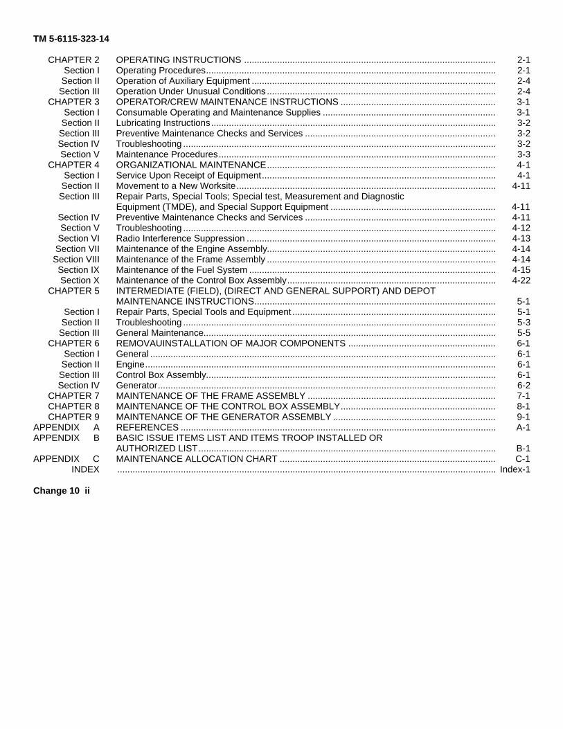
CHAPTER 2 OPERATING INSTRUCTIONS ................................................................................................... 2-1Section I Operating Procedures.................................................................................................................. 2-1Section II Operation of Auxiliary Equipment ................................................................................................ 2-4Section III Operation Under Unusual Conditions .......................................................................................... 2-4
CHAPTER 3 OPERATOR/CREW MAINTENANCE INSTRUCTIONS ............................................................. 3-1Section I Consumable Operating and Maintenance Supplies .................................................................... 3-1Section II Lubricating Instructions................................................................................................................ 3-2Section III Preventive Maintenance Checks and Services ........................................................................... 3-2Section IV Troubleshooting ........................................................................................................................... 3-2Section V Maintenance Procedures............................................................................................................. 3-3
CHAPTER 4 ORGANIZATIONAL MAINTENANCE.......................................................................................... 4-1Section I Service Upon Receipt of Equipment............................................................................................ 4-1Section II Movement to a New Worksite...................................................................................................... 4-11Section III Repair Parts, Special Tools; Special test, Measurement and Diagnostic
Equipment (TMDE), and Special Support Equipment ................................................................. 4-11Section IV Preventive Maintenance Checks and Services ........................................................................... 4-11Section V Troubleshooting ........................................................................................................................... 4-12Section VI Radio Interference Suppression .................................................................................................. 4-13Section VII Maintenance of the Engine Assembly.......................................................................................... 4-14Section VIII Maintenance of the Frame Assembly .......................................................................................... 4-14Section IX Maintenance of the Fuel System ................................................................................................. 4-15Section X Maintenance of the Control Box Assembly.................................................................................. 4-22
CHAPTER 5 INTERMEDIATE (FIELD), (DIRECT AND GENERAL SUPPORT) AND DEPOTMAINTENANCE INSTRUCTIONS............................................................................................... 5-1
Section I Repair Parts, Special Tools and Equipment ................................................................................ 5-1Section II Troubleshooting ........................................................................................................................... 5-3Section III General Maintenance................................................................................................................... 5-5
CHAPTER 6 REMOVAUINSTALLATION OF MAJOR COMPONENTS .......................................................... 6-1Section I General ........................................................................................................................................ 6-1Section II Engine.......................................................................................................................................... 6-1Section III Control Box Assembly.................................................................................................................. 6-1Section IV Generator..................................................................................................................................... 6-2
CHAPTER 7 MAINTENANCE OF THE FRAME ASSEMBLY .......................................................................... 7-1CHAPTER 8 MAINTENANCE OF THE CONTROL BOX ASSEMBLY............................................................. 8-1CHAPTER 9 MAINTENANCE OF THE GENERATOR ASSEMBLY ................................................................ 9-1
APPENDIX A REFERENCES ............................................................................................................................ A-1APPENDIX B BASIC ISSUE ITEMS LIST AND ITEMS TROOP INSTALLED OR
AUTHORIZED LIST..................................................................................................................... B-1APPENDIX C MAINTENANCE ALLOCATION CHART ..................................................................................... C-1
INDEX ..................................................................................................................................................... Index-1
Change 10 ii
TM 5-6115-323-14
Figure No
1-11-2
1-31-4
1-51-41-71-81-91-102-12-22-32-44-14-24-34-44-54-64-74-84-94-104-114-124-134-144-154-164-174-185-16-16-26-36-46-57-18-18-28-38-49-19-2
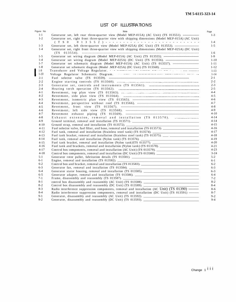
LIST OF ILLUSTRATIONSTitle
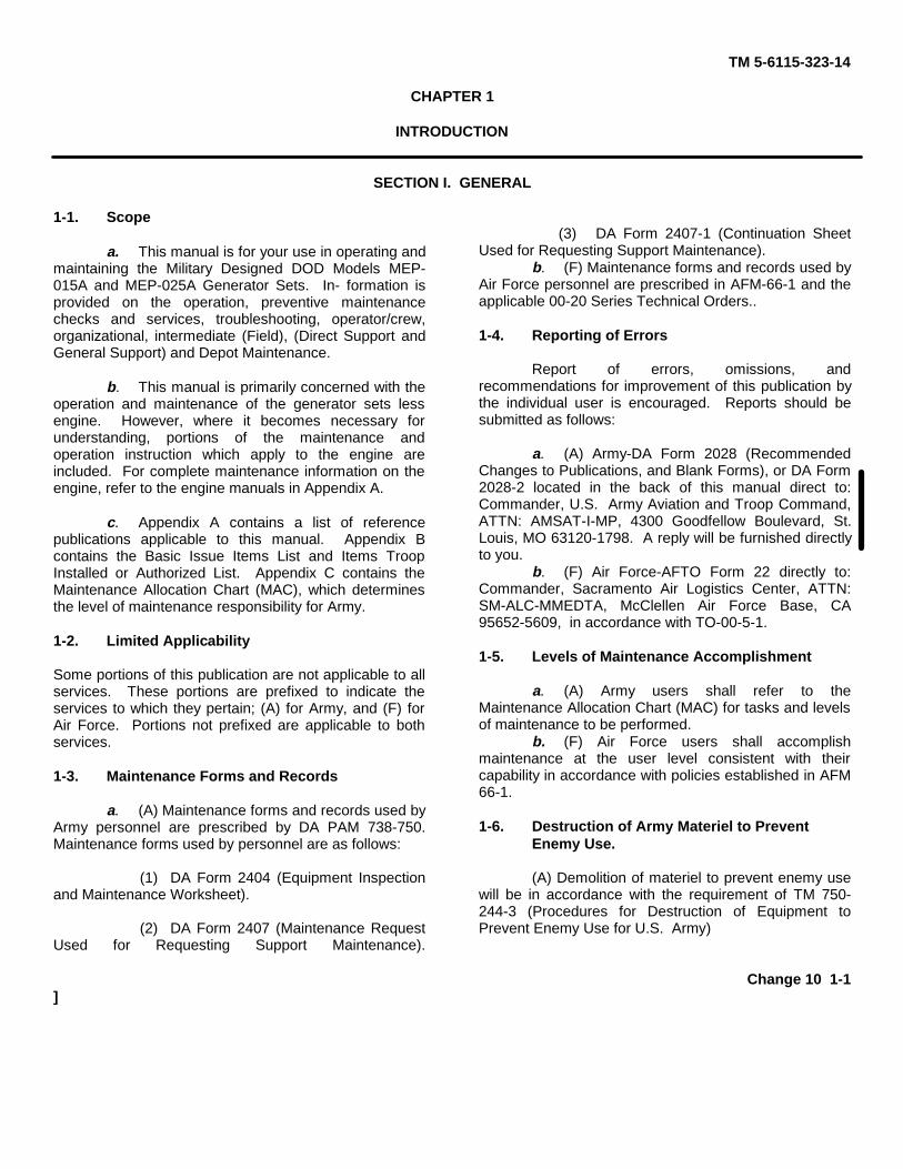
Generator set, left rear three-quarter view (Model MEP-015A) (AC Unit) (TS 013551). ----------------Generator set, right front three-quarter view with shipping dimensions (Model MEP-015A) (AC Unit)
( T S 0 0 1 3 5 5 2 ) - - - - - - - - - - - - - - - - - - - - - - - - - - -Generator set, left three-quarter view (Model MEP-025A) (DC Unit) (TS 013553). ------------------------Generator set, right front three-quarter view with shipping dimensions (Model MEP-025A) (DC Unit)
(TS 013554) . - - - - - - - - - - - - - - - - - - - - - - - - - - - - - - - - - - - - - - - - - - - - - - - - - - - - - - - - - - - - - - - - - - - - - - - - - - - - - - - - - - - - - -Generator set wiring diagram (Model MEP-015A) (AC Unit) (TS 013555). -----------------------------------Generator set wiring diagram (Model MEP-025A) (DC Unit) (TS 013556). ---------------------------------Generator set schematic diagram (Model MEP-015A) (AC Unit) (TS 013557). --------------------------Generator set schematic diagram (Model .MEP-025A) (DC Unit) (TS 013568). __________________________
Transducer and Voltage Regulator.Voltage Regulator Schematic Diagram.Fuel selector valve (TS 013559). --------------------------------------------------------------------------------Engine starting controls (TS 013560).Generator set, controls and instruments (TS 013561). Heating torch operation (TS 013562).Revetment, top plan view (TS 013563). Revetment, side plan view (TS 013564).Revetment, isometric plan view (TS 013565). --------------------------------------------------------Revetment, perspective without roof (TS 013566). ----------------------------------------------------Revetment, front view (TS 013567). ------------------------------------------------------------------Revetment, left side view (TS 013568). --------------------------------------------------------------Revetment exhaust piping (TS 013569). --------------------------------------------------------------E x h a u s t e x t e n s i o n , r e m o v a l a n d i n s t a l l a t i o n ( T S 0 1 3 5 7 0 ) . Ground terminal, removal and installation (TS 013571). ______________________________________________Ground strap, removal and installation (TS 013572). __________________________________________________Fuel selector valve, fuel filter, and hose, removal and installation (TS 013573). ________________________Fuel tank, removal and installation (Stainless steel tank) (TS 013574). ________________________________Fuel tank bracket, removal and installation (Stainless steel tank) (TS 013575). ____ ____________________Fuel tank, removal and installation (Nylon tank) (TS 013576). ________________________________________Fuel tank bracket, removal and installation (Nylon tank)’(TS 013577). ________________________________Fuel tank and brackets, removal and installation (Nylon tank) (TS 013578). __________________________Control box components, removal and installation (AC Unit) (TS 013579). ____________________________Control box components, removal and installation (DC Unit) (TS 013580). ____________________________Generator rotor puller, fabrication details (TS 013581). ______________________________________________Engine, removal and installation (TS 013582). ________________________________________________________Control box and bracket, removal and installation (TS 013583). ______________________________________Generator fan, removal and installation (TS 013584). ________________________________________________Generator stator housing, removal and installation (TS 013585). ______________________________________Generator adapter, removal and installation (TS 013586). ____________________________________________Frame, disassembly and reassembly (TS 013587). ____________________________________________________control box disassembly and reassembly (AC Unit) (TS 013588). ______________________________________Control box disassembly and reassembly (DC Unit) (TS 013589). ______________________________________Radio interference suppression components, removal and installation (AC Unit) (TS 01390) --------Radio interference suppression components, removal and installation (DC Unit) (TS 013591) ----------Generator, disassembly and reassembly (AC Unit) (TS 013592). ______________________________________Generator, disassembly and reassembly (DC Unit) (TS 013593). ______________________________________
Page
1-3
1-41-5
1-61-91-101-111-121-131-142-12-22-32-54-44-54-64-74-84-94-104-144-144-154-164-174-184-194-204-214-233-245-26-16-26-36-36-47-28-28-48-68-79-29-4
Change 1 i i i

TM 5-6115-323-14
Figure Number
3-13-23-34-14-25-15-2
iv
LIST OF TABLESTitle
Consumable Operating and Maintenance Supplies.Operator/Crew Preventive Maintenance Checks and Services. Troubleshooting.Organizational Preventive Maintenance Checks and Services.Troubleshooting.Special Tools, Test, and Support Equipment (Including Fabricated Items).T r o u b l e s h o o t i n g .
Page
3-13-23-34-124-125- l5-3
TM 5-6115-323-14
CHAPTER 1
INTRODUCTION
SECTION I. GENERAL
1-1. Scope
a. This manual is for your use in operating andmaintaining the Military Designed DOD Models MEP-015A and MEP-025A Generator Sets. In- formation isprovided on the operation, preventive maintenancechecks and services, troubleshooting, operator/crew,organizational, intermediate (Field), (Direct Support andGeneral Support) and Depot Maintenance.
b. This manual is primarily concerned with theoperation and maintenance of the generator sets lessengine. However, where it becomes necessary forunderstanding, portions of the maintenance andoperation instruction which apply to the engine areincluded. For complete maintenance information on theengine, refer to the engine manuals in Appendix A.
c. Appendix A contains a list of referencepublications applicable to this manual. Appendix Bcontains the Basic Issue Items List and Items TroopInstalled or Authorized List. Appendix C contains theMaintenance Allocation Chart (MAC), which determinesthe level of maintenance responsibility for Army.
1-2. Limited Applicability
Some portions of this publication are not applicable to allservices. These portions are prefixed to indicate theservices to which they pertain; (A) for Army, and (F) forAir Force. Portions not prefixed are applicable to bothservices.
1-3. Maintenance Forms and Records
a. (A) Maintenance forms and records used byArmy personnel are prescribed by DA PAM 738-750.Maintenance forms used by personnel are as follows:
(1) DA Form 2404 (Equipment Inspectionand Maintenance Worksheet).
(2) DA Form 2407 (Maintenance RequestUsed for Requesting Support Maintenance).
(3) DA Form 2407-1 (Continuation SheetUsed for Requesting Support Maintenance).
b. (F) Maintenance forms and records used byAir Force personnel are prescribed in AFM-66-1 and theapplicable 00-20 Series Technical Orders..
1-4. Reporting of Errors
Report of errors, omissions, andrecommendations for improvement of this publication bythe individual user is encouraged. Reports should besubmitted as follows:
a. (A) Army-DA Form 2028 (RecommendedChanges to Publications, and Blank Forms), or DA Form2028-2 located in the back of this manual direct to:Commander, U.S. Army Aviation and Troop Command,ATTN: AMSAT-I-MP, 4300 Goodfellow Boulevard, St.Louis, MO 63120-1798. A reply will be furnished directlyto you.
b. (F) Air Force-AFTO Form 22 directly to:Commander, Sacramento Air Logistics Center, ATTN:SM-ALC-MMEDTA, McClellen Air Force Base, CA95652-5609, in accordance with TO-00-5-1.
1-5. Levels of Maintenance Accomplishment
a. (A) Army users shall refer to theMaintenance Allocation Chart (MAC) for tasks and levelsof maintenance to be performed.
b. (F) Air Force users shall accomplishmaintenance at the user level consistent with theircapability in accordance with policies established in AFM66-1.
1-6. Destruction of Army Materiel to Prevent Enemy Use.
(A) Demolition of materiel to prevent enemy usewill be in accordance with the requirement of TM 750-244-3 (Procedures for Destruction of Equipment toPrevent Enemy Use for U.S. Army)
Change 10 1-1]

TM 5-6115-323-14
1-7. Administrative Storage
If the generator sets must be placed in adminis-trative storage proceed as follows:
a. (A) Army.(1) Store equipment so as to provide maxi-
mum protection from the elements and to provideaccess for inspection, maintenance, and exercis-ing. Anticipate removal or deployment problemsand take suitable precautions. For example, stra-tegically locate recovery vehicles, snowplows,slave units, and similar items, likely to be neededon short notice.
(2) Take into account environmental condi-tions, such as extreme heat or cold; high humid-ity; blowing sand, dust, or loose debris; softground; mud; heavy snows; earthquakes; or com-binations there of and take adequate precautions.
(3) Establish a fire plan and provide for ade-quate firefighting equipment and personnel.
(4) For further information, refer to TM 740-90-1 (Administrative Storage).
b. (F) Air Force. Refer to TO 35-1-4 (Processingand Inspection of Aerospace Ground Equipment).
1-8. Preparation for Shipment and Storage
If the generator sets must be placed in storageor shipped to another location, proceed as follows:
a. (A) Army. Refer to TM 740-90-1 (Administra-tive Storage) and TB 740-97-2 (Preservation ofUSAMECOM Mechanical Equipment for Shipment and Storage).
b. (F) Air Force. Refer to TO 35-1-4 (Processingand Inspection of Aerospace Ground Equipment)for the end item generator sets and TO 38-1-5(Processing and Inspection of Non-Mounted, Non-Aircraft Gasoline and Diesel Engines for Storageand Shipment) for the installed engine.
Section Il. DESCRIPTION AND DATA
1-9. Descriptionsuitable for use in a variety of applications that
The military design generator sets, DOD Model can be served by small, portable, generating unitsMEP-015A (AC Unit) (figs. 1-1 and 1-2), and DOD when used within the limits of their voltage,Model MEP-025A (DC Unit) (figs. 1-3 and 1-4), are frequency, and power characteristics. The unitsdesigned for general purpose use for lighting and consist primarily of the generator, control box,to provide power for pumps, blowers, heaters, engine, fuel tank, and frame. Both generator setscompressors and similar equipment. They are have a capacity of 1.5 KW (kilowatts).
1-2
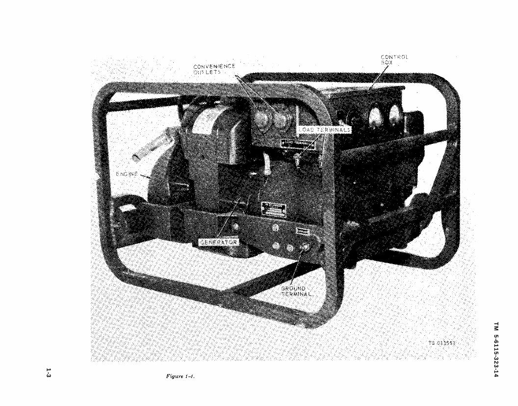
Figure 1-1.
Figure 1-1.
TM
5-6
11
5-3
23
-14
1-3
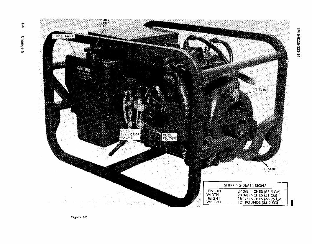
Figure 1-2.
Figure 1-2.
TM 5-6115-323-14
1-4C
hange 5
TM 5–6115-323-14
Figure 1-3. Generator set, left rear three-quarter view (Model MEP-025A) (DC Unit).
1–10. Identification and Tabulated Data
a. Identification. The generator sets are pro-vided with unit, engine, and generator identifica-tion plates. The information contained on theseplates is listed in subparagraph d, tabulated data.
b. Explanation of Military Design Generator SetSerial Numbers. The serial number of a militarydesign generator set (end item) is comprised offour alpha-numeric characters to which are ap-pended a numeric series that corresponds, inquantity, to the number of sets furnished.
(1) The first character (alpha) specifies themanufacturer. It is defined as follows:
G -------- Hol-Gar Manufacturing Co.K -------- John R. Hollingsworth Manufac-
turing Co.
N -------- Chimera Corp.Q ---- - - - - American Marc,
Corp.Div. of EON
R --------------- Aircraft Appliance and Equip-ment
(2) The second character (alpha) denotes thefrequency characteristics:
A -------- 60 HertzB -------- 28 Volt DC(3) The third and fourth characters (numeric)
represent the year of delivery.(4) On some units, the fifth, sixth and seventh
characters represent the unit sizes in KW and theremaining characters represent the unit numberin the series.
c. Explanation of Department of Defense (DODModel Designations.) The DOD family of mobile
1-5

Figure 1-4.
Figure 1-4.
TM 5-6115-323-14
1-6C
hange 5

electric power sources (MEP) model number as-signments for this series follows:
Spark Ignition Engine Driven (SIED)Rating in KW DC 60 Hertz
1.5 025A 015A
(1) AC Unit, NSN 6115-00-889-1446, appliesto Generator Sets, 1.5 KW, Military Design, 60Hertz, DOD Model MEP-015A, serial numberranges GA64-1 through GA64-7525, GA65-0001through GA65-4579, GA67-0001 through GA67-6807, NA68-0001 through NA68-0829, GA69-001through GA69-1250, R A 7 1 0 0 0 1 t h r o u g hRA714666, KA7201.50001 through KA7201.57488,KA73500001 through KA73507085, a n dGA741.5001 through GA741.57079, hereafter re-ferred to as the AC Unit.
(2) DC Unit, NSN 6115-00-017-8236, appliesto Generator Sets, 1.5 KW, Military Design, 28Volt DC, DOD Model MEP-025A, serial numberranges GC64–1 through GC64-5915, GS65-0001through GS65–2563, GS66-0001 through GS66-11947 and RA710001 through RA714666, hereafterreferred to as the DC Unit.
d. Tabulated Data.
(1) Generator set, AC unit, NSN 6115-00-889-1446.
Manufacturer DOD Model MEP-015A -_
Part Number ------------
National Stock Number Specification ------------Contract Number --------
Serial Number Range Contract Number
Serial Number Range Contract Number --------
Serial Number Range Contract Number
Serial Number Range Manufac turer DOD Model MEP-015A
National Stock Number Contract Number
Serial Number Range Manufacturer ------------
Centract Number Serial Number Range
Manufacturer ------------
Contract Number --------Serial Number Range
Hol-Gar Mfg. Corp.Formerly Hol-Gar Model CE-
016-AC, and Military DesignModel SG-1.5MD
Hol-Gar 21251; MERDC13214E0100
6115-00-889-1446MIL-G-52282 (MO)DA 11-184-AMC-560 (T)GA64-1 thru GA64-7525DA 23-195-AMG0017 (T)GA65-001 thru GA65-4579DAAK01-67-C-1489GA67-0001 thru GA67-6807DAAK01-69-C-5285GA69-0001 thru GA69-1250Chimera Corp.Formerly Chimera Corp. Model
MD105-1-2-M6115-00-889-1446DAAK01-68-C-8540NA68-0001 thru NA68-0829American Marc, Div. of EON
Corp.DAAK01-69-C-A359QA6901.500001 thru QA6901.517102Aircraft Appliance and Equip
mentDSA 400-71-C-007RA71OOO1 thru RA714666
Manufacturer Contract Number
Serial Number Range
Manufacturer Contract Number
Serial Number Range M a n u f a c t u r e r Contract Number
Serial Number Range
TM 5-6115-323-14
Hollingsworth Mfg. Corp.DSA 400-72-C-2974KA7201.50001 thru KA7201.57488Hollingsworth Mfg. Corp.DSA 400-73-C-7063KA73500001 thru KA73507085Hol-Gar Mfg. Corp.DSA 400-73-C-8041GA741.50001 thru GA741.57079
(2) Generator set, DC unit, NSN 6115-00-017-8236. (Same as AC Unit unless otherwise indi-cated.)
Manufacturer ------------DOD Model MEP-025A --
Part Number ------------
National Stock Number SpecificationContract Number
Serial Number Range Contract Number --------
Serial Number Range --Contract Number --------
Serial Number Range Manufac turer DOD Model MEP-025A
National Stock Number --Contract Number
Serial Number Range Duty Mounting
Control Fuel capacity Operating speed Radio suppression
(3) Engine.
Type
Part Number National Stock Number References --------------
Hol-Gar Mfg. Corp.Formerly Hol-Gar Model CE-
017-DC and Military DesignModel DC-1.5-MD/28 V, DC
Hol-Gar 20070; MERDC13213E-2700
6115-00-889-1446MIL-G-52283DA 11-184-AMC-566 (T)GC64-1 thru GC64-5915DA 23-195-AMC-00175 (T)GC65-0001 thru GC65-2563DA 23-195-AMC-00423 (T)GC66-0001 thru GC66-11947John R. Hollingsworth Corp.Formerly Hollingsworth Model
JHGV1.5A and Military De-sign Model DC-1.5-MD/28 V,DC
6115--00-017-8236DSA 400-71-C-6007RA710001 thru RA714666ContinuousSkid, shock mounted, tubular
frameLocal1 1/2 gallons (5.7 liters)3600 rpmMIL-STD-461 Class III B
Government furnished, Mili-tary Standard, Gasoline, 3,HP, Model 2A016-3
97887E3 (97403)2805-00-072-4871See Appendix A
(4) Generator assembly, AC unit.
Type FrequencySpeed Temperature risePower Power factor Voltage Current Duty Altitude rating
AC, brushless, self-excited60 Hertz3600 rpm75° C. (167° F.)1.5 KW1.0120/240 VAC, single phase12.50/6.25 amperesContinuous1.5 KW below 8,000 ft. (2,400
meters)
1 - 7

TM 5-6115-323-14
(5) Generator assembly, DC unit.
Type . . . . . . . . . . . . . . . . . . . . . . . . . . . . . DC, brushless, self-excitedFrequency.. . . . . . . . . . . . . . . . . . . . DCSpeed ..................... 3600 rpmT e m p e r a t u r e r i s e . . . . . . . . . 75°C.(1670F.)Power . . . . . . . . . . . . . . . . . . . . . . . . . . . 1.5 KWVoltage.. . . . . . . . . . . . . . . . . . . . . . . . . . . . 28VDCCurrent ............................ 53.5 amperesDuty . . . . . . . . . . . . . . . . . . . . . . . . . . . . Cont inuousAltitude rating ..................... 1.5 KW level to 8,000 ft.
(2,400 m))
e. Dimensions and Weight, AC and DC Units(figs. 1-2 and 1-4).
f. Generator Repair and Replacement Standard.
(1) Alternator rotor.
Resistance of connected 15.5 ohms ± 5% windings at 77°F. (25 °C.)
(2) Exciter rotor.
Resistance between lead 5.84 ohms ± 10% pairs at 77°F. (25 °C.)
(3) AC unit alternator stator.
Resistance between lead 1.32 ohms ± 10% pairs (T1-T2 and T3-T4)at 77°F. (25°C. )
(4) DC unit alternator stator.
Resistance between lead -0.031 ohms ±20% pairs (T1l-T12,T12-T13, T-14-T15, T15-T1l) at 77°F, (25°C.)
(5) Excitation windings.
Resistance (T1-T2) at 8.2 ohms ± 10% (77°F. (25°C. ))
(6) Exciter stator.
Resistance of winding at 215 ohms ± 10% 77°F. (25°C.)
(7) Voltage regulator.
Winding resistance at 77°F. (25°C. )Coil C1A-C2B 36 ohms ± 10%Coil C2A-C2B 12.2 ohms ±10%Coil C3A-C3B 36 ohms ± 10%
Voltage Operating Range AC DC
Minimum range from no 110 to 130 V 23-36 Vload to rated load, 225 to 255 Vambient temp.
At extreme temperatures 120V±5% 28 V ± 4% -65°F. (-54°C.) and 220 v ± 5%125°F. (52°C. )
RegulationNo load to rated load and 120 v ± 4% 28 V ± 4%
rated load to no load 220 v ± 5%Steady State Regulation AC
At constant load from no 120 v ± 170 28 V ± 1%load to rated load 220 V ± 1%
g. Generator Assembly Nut and Bolt Torque Data.
Generator-to-adapter platescrews 8 to 10 ft. lbs.
Through stud 16 to 18 ft. lbs.Baffle-to-generator screws 8 to 10 ft. lbs,Rectifiers 20 to 25 ft. Ibs.
h. Wiring Diagrams. Figures 1-5 and 1-6 show thewiring diagrams that are applicable to the generatorsets.
i. Schematic Diagrams. Figures 1-7 and 1-8 showthe schematic diagrams that are applicable to thegenerator sets.
1-11. Differences Between Models
The differences between the Model MEP-015A (ACUnit) and the Model MEP-025A (DC Unit) are minordifferences in the design of the control box, a changein the windings of the stator, and the addition of rec-tifiers and heat sinks in the DC generator. Where dif-ferences exist, each model is covered separately in theapplicable maintenance sections of this manual.
1-8 Change 5
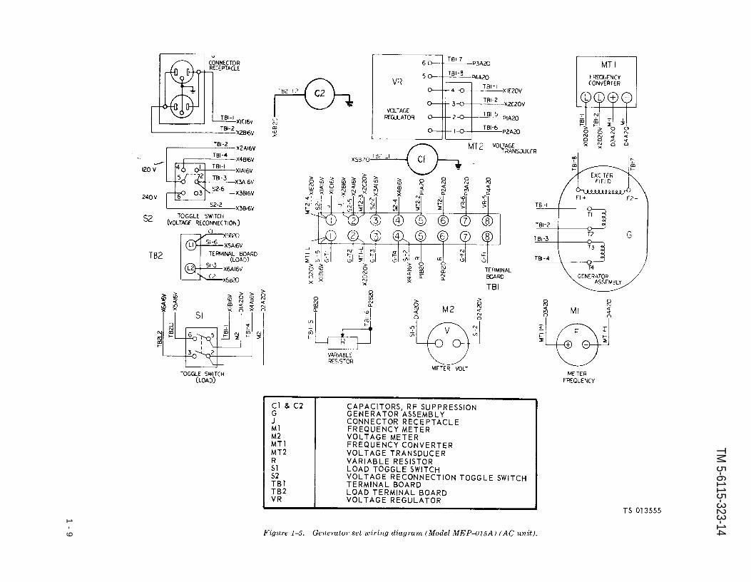
Figure 1-5.
TM 5-6115-323-14
1-
9

Figure 1-6.
TM 5-6115-323-14
1-1
0

Figure 1-7.
iiTM 5-6115-323-14
Change 1 1 -11

Figure 1-8.
TM 5-6115-323-14
1 - 1 2

Figure 1-9.
TM 5-6115-323-14
Change 1 1 - 1 3

Figure 1-10.
TM5-6115-323-14
1-14 Change 1

TM 5-6115-323-14
CHAPTER 2
OPERATING INSTRUCTIONS
Section I. OPERATING PROCEDURES
2-1. Controls and Instrumentsa. General. This paragraph provides information
about the various controls and instruments forproper operation of the generator sets.
b. Fuel Selector Valve. The fuel selector valve(fig. 2-1) is a four-position, rotary-type valve thatis used to turn the fuel supply off, or to selectbetween an external fuel supply and the on-settank. It is located in front of the fuel tank on theright side of the generator set.
c. Engine Off-Run Switch. The engine off-runswitch (fig. 2-2), a two position, toggle-type switch,is used to stop the engine when the switch hasbeen positioned in the OFF position. The enginecan be started after the switch has been posi-tioned in the RUN position.
d. Choke Lever. The choke lever (fig. 2-2), adouble-armed lever, is secured to the choke shaftat the front of the carburetor. It is normally keptin the OPEN position. To choke the engine, rotatethe lever in a counterclockwise direction.
Figure 2-1. Fuel selector valve
2-1

TM 5-6115-323-14
e. If the engine does not start, close choke to full.Take one pull of starter rope. If engine starts, run
Figure 2-2. Engine starting controls.Step 1. Set the circuit breaker to OFF or OPEN position.
I
Step 2. Set the fuel selector valve to the TANK or AUXposition–whichever fuel source you are using.
Step 3. Set the output selector switch-it is inside the con-trol box–to the generator (voltage) output thatmatches the connected load.
Step 4. Turn the voltage adjusting rheostat all the way tothe left.
Step 5. Set the carburetor throttle control in GOVERN orRUN position.
Step 6. a. Set the engine RUN-OFF switch to RUNposition.b. Put the choke in about a 3/4-closed position.
WARNING
Serious eye injury can result from thestarter rope knot. Wear eye protectionwhen pull starting engine.
engine at l/2-choke, then open choke as steady engine operation permits.
CAUTION
Unnecessary or excessive use of the chokecan cause the lubricating oil to dilute.
e. Carburetor Control. The carburetor control (fig.2-2) is a lever that is held in the selected position bya springloaded, knurled nut. The control assembly islocated at the top front of the carburetor at the rightfront of the engine. Engine speed can be increased bymoving the lever away from the engine and can bedecreased by moving the lever toward the engine.
f. AC Voltmeter (AC Unit). The AC voltmeter (A,fig. 2-3), located on the rear face of AC control box, in-dicates the voltages at end load toggle switch (S1).The meter is graduated from 0 to 250 volts. It normal-ly should read either 120 V or 240 V.
g. Frequency Meter (AC Unit). The frequencymeter (A, fig. 2-3) located next to the voltmeter on therear face of the control box, indicates the frequencyof the generator output. The frequency meter isgraduated from 55 to 65 CPS (cycles per second) =hertz. The normal reading should be 60 CPS (hertz).
h. Load Switch (AC Unit). The load switch (A, fig.2-3) is a toggle-type, two-position switch that islocated on the left side of the rear face of the controlbox. It is used to connect and disconnect thegenerator set to and from the load.
i. Variable Resistor (AC Unit). The variableresistor (A, fig. 2-3) is located on the rear face of thecontrol box. A rotary-type control, it is used to con-trol the output voltage of the generator set.
j. Voltage Change Switch (AC Unit). The voltagechange switch (A, fig. 2-3) is a two-position, pull-release, toggle-type switch. It is located at the top leftcenter of the control box under the cover. It is usedonly when setting up the equipment to adapt the uniteither to a 120 volt or 240 volt load.
k. DC Voltmeter(DC Unit). The DC voltmeter (B,fig. 2-3), located on the left rear face of the DC controlbox, indicates the voltage at the circuit breaker. Themeter is graduated from 0 to 50 volts. It should nor-mally read 28 volts.
c. Make one pull of the starter rope with a quick,steady motion.d. If the engine starts, open choke as steady engineoperation permits.
2-2 Change 5

TM 5-6115-323-14
l. DC Ammeter (DC Unit). The DC ammeter (B,fig. 2-3, located on the right rear face of the DCcontrol box, indicates the percentage of full-loadcurrent that the unit is supplying. It is graduatedfrom 0 to 125 percent. It should normally readbetween 0 and 100 percent.
m. Circuit Breaker (DC Unit). The circuitbreaker (B, fig. 2-3) is located to the left of the DC
ammeter on the rear of the DC control box. Thecircuit breaker is used to connect and disconnectthe unit to and from the load. The circuit breakeris designed to trip when 125% of maximum load isapplied.
n. Variable Resistor (DC Unit). The variableresistor (B, fig. 2-3) is located to the right of theDC voltmeter on the rear face of the control box.
Change 6 2-2.1/(2-2.2 Blank)


TM 5-6115-323-14
Figure 2-3. Generator set, controls and instruments.
Change 5 2 - 3

TM 5-6115-323-14
A rotary-type control, it is used to control theoutput voltage of the generator set.
2-2. Operation Under Usual Conditions
a. General.(1) The instructions in this paragraph are
published for the information and guidance ofpersonnel responsible for operation of the genera-tor sets.
(2) The operator must know how to performevery operation of which the generator sets arecapable. This section gives instructions on starting and stopping the generator sets and regulat-ing them to perform the specific task for whichthe equipment is designed.
WARNING
Operation of this equipment presents anoise hazard to personnel in the area.The noise level exceeds the allowablelimits for unprotected personnel. Wearear muffs or ear plugs which were fittedby a trained professional.
b. Starting.(1) Preparation for Starting
(a) (A, F, N, MC) Perform the daily preven-tive maintenance checks and services (Table 3-2).
(b) Check the load cable connections, posi-tion arrow on knob of variable resistor so it pointsUP, set the load switch (S1) on the AC unit or thecircuit breaker (CB) on the DC unit in the OFFposition.
(c) On the AC unit only, remove the coverof the control box and see that the voltage changeswitch (S2) is in the desired position (120 or 240volts), Install the cover.
(b) Position the fuel selector valve in posi-tion for either the on-set tank or for an auxiliaryfuel supply.
(2) Starting. Refer to figure 2-2 and start theengine.
c. Operation. Position the load switch (AC Unit)(A, fig. 2-3) or circuit breaker (DC Unit) in the ONposition and turn the knob of the variable resistorto set the output voltage to the proper value,either 120 volts or 240 volts AC, or 28 volts DC.
d. Stopping.
(1)
(2)
(3)
Set the circuit breaker/load switch toOFF position.Turn the voltage adjusting rheostat allthe way to the left.Run the generator set at rated speed forthree to five minutes to cool down theset.
(4) Move the engine RUN switch to OFF.
Section Il. OPERATION OF AUXILIARY EQUIPMENT
2-3. Heating Torch Description CAUTION
The heating torch is aline, pump-type torch. Itengine to a point whereoperate freely.
l-pint (.47 liters), gaso- Move heating torch continuously whileis used to preheat the heat is being applied. This will preventthe moving parts will damage to the engine crankcase from
overheating any single spot thereon. Donot apply direct heat or flame to thenylon fuel tank, fuel lines, and fuel filter
2-4. Heating Torch Operationsystem.
Operate the heating torch as shown by figure 2-NOTE
The heating torch should be applied at the apera-4. tures (four on each side) beneath both sides of the
engine.
2-4 Change 1

T M 5 - 6 1 1 5 - 3 2 3 - 1 4
Figure 2-4. Heating torch operation
2 - 5

TM 5-6115-323-14
Section Ill. OPERATION UNDER UNUSUAL CONDITIONS
2-5. Operation in Extreme Cold (Below 0°F.(- 18°C.))
a. General. The generator sets are designed foruse in outdoor temperatures as low as –65°F.(–5°C.). Even so, when possible, provide shelterfrom winds, freezing rain, and drifting snow.Erect a wind shield or position the unit behind abuilding, equipment, or natural wind barrier suchas a rock or earth mound. If possible, operate theunit in a location that will provide protection forthe operator so as to permit easier servicing andbetter observation of the unit’s performance.However, when the unit is operated in an inclosedarea, be sure that proper provisions are made forremoval of exhaust gases. Remove accumulatedsnow or ice, if possible, by moving the unit to aheated inclosure and allowing the accumulation tomelt after first wiping or brushing away loosedeposits. When use of a heated inclosure is notpractical, remove the deposits by wiping, brush-ing, or carefully picking the deposits away. Becareful not to scrape, scratch, gouge, or in anyother way damage the unit. Avoid moving wiringas much as possible. Any time ice or snow isremoved by melting, as described above, changethe oil in the crankcase and dry electrical partsthoroughly.
b . E n g i n e ( – 2 5 ° F . to – 6 5 ° F . ) ( 3 2 ° C . t o–54°C.)).
(1) Lubricate the engine in accordance withLO 5-2805-257-12. Air Force will use the lubrica-tion section of applicable T.O. 35C2-3-1-426 Serieswork cards.
WARNING
Use extreme care, when using a torch,to keep flame away from the fuel tank.Do not use a torch, if any fuel leaks areevident, until leaks have been correctedand both the unit and the surroundingarea is dry of fuel that has leaked.
(2) To aid in starting, apply heat to the en-gine with a suitable torch, such as a torch thatconforms to MIL–H–52112, Type I (para 2-4). Playthe torch flame back and forth over the intakemanifold, oil pan, valve covers and air intake. Donot hold the flame in one spot. Keep flame andheat away from nonmetallic parts.
(3) When the engine has been warmed, at-tempt to start. If it fails to start, reapply heat, asnecessary.
2 - 6
(4) After the engine has been started, keep itrunning for at least 30 minutes in order to reducecondensation of moisture in the crankcase. Avoidoperation for short periods of time.
c. Generator and Controls.(1) Remove the end cover and clean the cover.(2) Carefully remove any accumulations of ice
or snow from around the rotor.(3) When using the generator in extreme cold,
allow at least a 15-minute stabilization periodbefore applying load to the unit.
(4) Keep generator controls and instrumentsfree of snow and ice. Avoid moving wiring, toprevent cracking of insulation.
d. Fuel System.(1) Keep snow and ice out of the fuel supply.(2) Keep the fuel tank full when the unit is
not in operation.(3) Use the proper fuel.(4) Inspect the bowl of the fuel filter fre-
quently for accumulated moisture and if any isseen, clean as necessary.
(5) Avoid unnecessary bending of fuel hoses.
2–6. Operation in Extreme Heat
a. General. Whenever possible, operate the unitin a shaded location that is away from sources ofheat. If the unit must be used in an area that isadjacent to a heat source, erect a heat shield or insome way block the direct source of heat. Provideplenty of ventilation and vent the exhaust gasesto the outside when the unit is to be operated inan inclosed area.
b. Engine.(1) Lubricate the engine in accordance with
LO 5-2805-257-12. Air Force will use the lubrica-tion section of applicable T.O. 35C2–3-1-426 Seriesworkcards.
(2) Keep all engine air passages clean andfree of obstructions.
c. Generator. Keep the end cover openings cleanand free of obstructions.
d. Generator Controls and Instruments. Keepopenings in the control box clean, so as to providefor free air flow. However, operate the unit withthe control box cover installed.
e. Fuel System. Fill fuel tank only to within oneinch of the top to allow for expansion of the fuel.

TM 5-6115–323-14
2–7. Operation in Dusty or Sandy Areas
a. General. If the installation is expected to belengthy, erect a protective shield for the unit toprotect it from dust and sand. If the installation istemporary, utilize a natural or improvised barrierwhen possible. Clean dust and dirt from the unitat frequent intervals.
b. Engine. Clean the air cleaner and fuel filtermore frequently. Clean the engine at more fre-quent intervals to remove accumulated dust anddirt.
c. Generator. Keep the end cover clean.
d. Generator Controls and Instruments. Care-fully clean dust and sand out of the control box,Do not allow dust to accumulate around terminalsor voltage regulator.
e. Fuel system. Keep the area around the fueltank cap clean and free from dust and sand. Keepall fuel supplies capped to prevent the entrance ofdust.
2-8. Operation Under Rainy or HumidConditions
a. General. When the generator set is to beoperated outdoors, provide a shelter, if possible, toprotect the unit. If shelter is not available anderection of one is not practical, keep the unit,when inoperative, covered with waterproof mate-rial. Remove the cover during dry periods to allowthe unit to dry out.
b. Fuel. Keep the fuel tank as full as possible toprevent condensation.
c. Electrical System. Humid conditions cancause corrosion and deterioration of electricalcomponents. Keep electrical components and wir-ing clean and dry.
2–9. Operation in Salt Water Areas
a. General. Wipe the generator set with a cleancloth dampened with clean, fresh water at fre-quent intervals. Use care not to contaminate thefuel supply or damage the electrical system withwater.
b. Lubrication. Use care to keep salt water fromentering the engine when adding or changing oil.Lubricate more frequently than specified in LO 5-2805–257–12. Air Force will use the lubricationsection of applicable T.O. 35C2–3-1-426WC Seriesworkcards.
c. Preservation. Paint all exposed non-polishedsurfaces. Coat exposed parts of polished steel orother ferrous material with standard issue rust-proofing material if available or cover parts withone light coat of grease. Refer to the appropriateservice manual (See Appendix A).
2–10. Operation at High Altitudes
The generator set is designed to operate atelevations up to 8,000 feet above sea level withoutspecial service or adjustment. Provide adequateventilation as the engine is more likely to over-heat at high altitudes. It may be necessary tochange the fuel-air ratio of the engine; if so, referto organizational maintenance. To calculate theoutput capability at altitudes above 8,000 feet, usethe following formula and round figures to thenearest tenth:
7% x actual altitude – 8,000 x 1.5 kw= kw derating1000
0.07 X 13,000 – 8,000Example: x 1.5 kw = .525 kw derating
10001.5 kw – .525 kw = .975 kw derated power at 13,000 ft.
2–7

TM 5-6115-323-14
CHAPTER 3
OPERATOR/CREW MAINTENANCE INSTRUCTIONS
Section I. CONSUMABLE OPERATING AND MAINTENANCE SUPPLIES
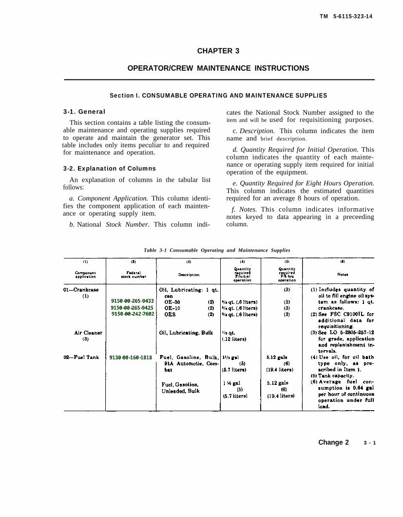
3-1. General
This section contains a table listing the consum-able maintenance and operating supplies requiredto operate and maintain the generator set. Thistable includes only items peculiar to and requiredfor maintenance and operation.
3-2. Explanation of Columns
An explanation of columns in the tabular listfollows:
a. Component Application. This column identi-fies the component application of each mainten-ance or operating supply item.
cates the National Stock Number assigned to theitem and will be used for requisitioning purposes.
c. Description. This column indicates the itemname and brief description.
d. Quantity Required for Initial Operation. Thiscolumn indicates the quantity of each mainte-nance or operating supply item required for initialoperation of the equipment.
e. Quantity Required for Eight Hours Operation.This column indicates the estimated quantitiesrequired for an average 8 hours of operation.
f. Notes. This column indicates informativenotes keyed to data appearing in a preceeding
b. National Stock Number. This column indi- column.
Table 3-1 Consumable Operating and Maintenance Supplies
Change 2 3 - 1
Richard Woods
9150-00-265-9433
Richard Woods
9150-00-265-9425
Richard Woods
9150-00-242-7602
Richard Woods
9130-00-160-1818

TM 5-6115-323-14
Section Il. LUBRICATING INSTRUCTIONS
Lubrication is not required for the generator. For LO 5-2805-257-12. Air Force will use the applicablegeneral lubrication information on the engine, refer to T.O. 35C2-3-1-426 Series workcards.
Section Ill. PREVENTIVE MAINTENANCE CHECKS AND SERVICES (PMCS)
3-3. General
To insure that the generator set is ready for opera-tion at all times, it must be inspected systematicallyso that defects may be discovered and correctedbefore they result in serious damage or failure. Thenecessary daily preventive maintenance services to beperformed are listed and described in paragraph 3-4.Item numbers indicate the sequence of minimum in-spection requirements. Defects discovered duringoperation of the unit shall be noted for future correc-tion, to be made as soon as operation has ceased. Stopoperation immediately if a deficiency is noticed whichwould damage the equipment if operation werecontinued.
3-4. Daily Preventive Maintenance Checks andServices
Table 3-2 contains a tabulated listing of preventivemaintenance checks and services which shall be per-formed by the Operator/Crew personnel. The itemnumbers are listed consecutively and indicate thesequence of minimum requirements.
NOTELeakage definitions for operator/crew PMCS shall be
Class I
Class II
Class III
classified as follows:
Seepage of fluid (as indicated by wetnessor discoloration) not great enough toform drops.
Leakage of fluid great enough to formdrops but not enough to cause drops todrip from item being checked/inspected.
Leakage of fluid great enough to formdrops that fall from the item being check-ed/inspected.
CAUTION
Equipment operation is allowable withminor leakages (Class I or II). Of course,you must consider the fluid capacity in theitem/system being checked/inspected.When in doubt, notify your supervisor.
When operating with Class I or Class IIleaks, continue to check fluid levels as re-quired in your PMCS.
3 - 2 Change 5

TM 5-6115-323-14
Table 3-2. OPERATOR/CREW PREVENTIVE MAINTENANCE CHECKS AND SERVICES
B - BEFORE OPERATION A - AFTER OPERATIOND -DURING OPERATION
ItemN o . Interval
Item Procedures Equipment isto be Check for and have
B D A inpected repaixed or adjusted as necessary available if:
1 ● Generator set a. Check generator set for tight ground Generator set is notconnections and proper ground rod installation. grounded properly.
● ● b. Check for fuel and Oil leaks. Class I fuel leak detectedor class III oil leakdetected.
● c. Inspect for loose, damaged, or missing parts Any loose, damaged, orand unusual wear or deterioration. missing parts; (i.e., spark
plugs, manifolds, starter,or other items).
2 ● Oil gage rod Check crankcase oil level. Add oil as required
3 ● Gages and Check for proper generator operationInstruments
● a. Voltmeter Adjust for desired voltage. Rotate voltage Voltage cannot be adjusted.selector switch to monitor the various outputvoltage combinations (120 or 240).
● b. Frequency meter Normal indication: MEP-015A, 60 Hz Indicates frequency too(59 to 61 Hz). high or too low.
● c. Load meter Indicates percentage of applied load. Rotate Meter indication exceedscurrent selector switch to monitor the load 125%.applied to each phase. Not to exceed 125%.
4 Fuel tankWARNINGWhen handling gasoline, always provide ametal-to-metal contact between thecontainer and fuel tank. This will preventa spark from being generated as gasolineflows over the metallic surfaces.Never service generator set when inoperation.
● After operation, fill tank to prevent moisturecondensation.
Change 8 3-2.1
TM 5-6115-323-14
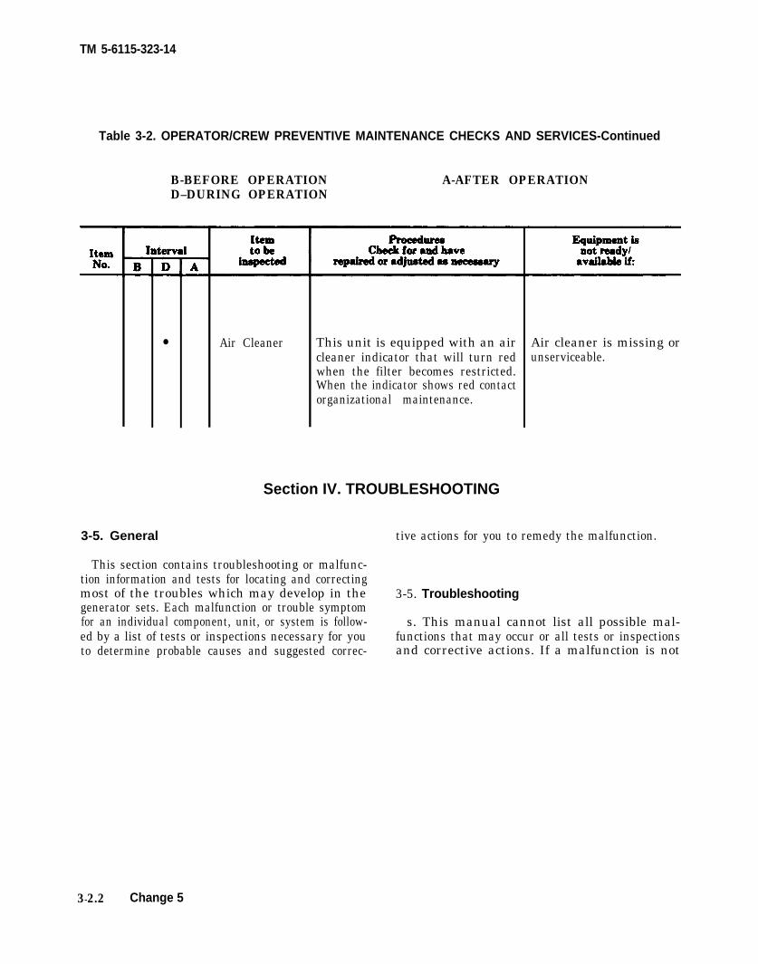
Table 3-2. OPERATOR/CREW PREVENTIVE MAINTENANCE CHECKS AND SERVICES-Continued
B-BEFORE OPERATION A-AFTER OPERATIOND–DURING OPERATION
3-5. General
● Air Cleaner This unit is equipped with an aircleaner indicator that will turn redwhen the filter becomes restricted.When the indicator shows red contactorganizational maintenance.
This section contains troubleshooting or malfunc-tion information and tests for locating and correctingmost of the troubles which may develop in the 3-5. Troubleshootinggenerator sets. Each malfunction or trouble symptomfor an individual component, unit, or system is follow- s. This manual cannot list all possible mal-ed by a list of tests or inspections necessary for you functions that may occur or all tests or inspectionsto determine probable causes and suggested correc- and corrective actions. If a malfunction is not
3-2.2 Change 5
Section IV. TROUBLESHOOTING
Air cleaner is missing orunserviceable.
tive actions for you to remedy the malfunction.

listed (except when malfunction and cause areobvious), or is not corrected by listed correctiveactions, you should notify higher level mainte-nance.
b. Table 3% lists the common malfunctions thatyou may find during the operation or mainte-nance of the generator sets or their components.You should perform the tests/inspections and cor-rective actions in the order listed.
NOTEBefore you use this table, be sure you have per-formed all normal operational checks. If you havea malfunction which is not listed in this table,notify the next higher level of maintenance.Air Force users may perform maintenance withinthe scope of their capabilities.
Table 3-3. TROUBLESHOOTING
MALFUNCTIONTEST OR INSPECTION
CORRECTIVE ACTION
1. ENGINE FAILS TO START OR MAL-FUNCTIONSStep 1.
Step 2.
Step 3.
Step 4.
Step 5.
Check the fuel tank (figs. 4-12 and 4-I4) for
the proper fuel level..Fill the fuel tank (figs. 4-12 and 4-14) only towithin one inch of the top to allow f o rexpansion of the fuel.Visually inspect the position of the fuel selec-tor valve (fig. 2-1).Place the fuel selector valve in the correctposition which can be determined by readingthe instruction plate (fig. 2–1) located on theright side of the generator set.Check the auxiliary fuel hose for an air leak.Tighten any loose connections.Inspect the auxiliary fuel supply valve for the
correct positioning.Position the auxiliary fuel supply valve in theproper position.Inspect the fuel filter for dirt.
Clean the fuel filter. Refer to Appendix A forthe appropriate service document.
TM 5-6115-323–14
Table 3-3. TROUBLESHOOTING—Continued
MALFUNCTIONTEST OR INSPECTION
CORRECTIVE ACTION
2. NO POWER AT LOADStep 1. Check the load lines for improper connections
or breaks.Connect load lines properly or if broken,repair by replacing as follows:
a. Model MEP–015A (AC Unit). Use cablewith a minimum wire size of No. 12 AWG.
b. Model MEP–025A (DC Unit). Use, as aminimum size, cable of No. 4 AWG fordistances up to 25 ft. For longer distances,No. .3, No. 2, or No. 1 AWG sizes should beused.
Step 2. Check the circuit breaker (B, fig. 2-3) or loadswitch (A, fig. 2-3) to see if it is in the OFFposition.Place the circuit breaker or load switch inthe ON position. If the circuit breaker willnot stay in the ON position, refer the mal-function to the next higher maintenancelevel.
3. OUTPUT VOLTAGE HIGH OR LOWStep 1.
Step 2.
Check to see if the variable resistor (fig. 2-3)is correctly adjusted. The voltmeter readingwill change as the variable resistor knob isturned.Turn the variable resistor knob (labeled “ad-just volts” and “increase volts”) until therequired voltage is attained.Inspect the total load, it may be too large forthe generator.Reduce the load and see if the malfunction iscorrected. If not, refer to next highter level of maintenance.
4. UNIT CAUSES RADIO INTERFERENCEStep 1. Inspect the load lines far loose connections.
Tighten all load lines connections securely.Step .2. Inspect established ground for loose connec-
tion.Tighten all ground connections securely.
Section V. MAINTENANCE PROCEDURES
3-7. General stopped. Failure to observe this safety
This section contains information on the main-precaution could result in severe elec-
tenance of the equipment that is the responsibil-trical shock or death by electrocution.
ity of the operator. 3-8. Fuel Strainer, Fuel Filterr and Air
WARNING Cleaner
Before servicing any part of the genera- a. General. The fuel tank is equipped with ator set, make certain that the engine is removable strainer (5, fig. 4-16) that will strain
3 – 3

TM 5-6115–323-14
out the larger particles that could be found in thefuel supply. There are no other specific mainte-nance functions allocated to the operator on thegenerator, its controls, or on the structural compo-nents of the generator unit. However, the aircleaner and fuel filter, both components of theengine, will be serviced as required by the enginemaintenance allocation chart. For instructionsrelative to these components, refer to the enginetechnical manual. (See Appendix A for the appro-priate service manual.)
b. Fuel Strainer. To service the fuel strainer (5,fig. 4-16), remove the fuel tank cap (4, fig. 4-16)
and using the fingers, withdraw the fuel strainerfrom the fuel tank. Flush all foreign material fromthe inside of the strainer using clean fuel. Insertthe strainer into the fuel tank and install the cap.
3–9. Fuel Tank Cap and Chain Assembly
a. Inspect. Inspect the fuel tank cap and chainassembly (figs. 4-12 and 4-14) for cracks, breaks,loose fittings, and other obvious damage.
b. Removal and Installation. Refer to figure 4-16to remove and install the fuel tank cap and chainassembly.
3-4

TM 5-6115–323–14
CHAPTER 4
ORGANIZATIONAL MAINTENANCE
Section I. SERVICE UPON
4-1. Inspecting and Servicing the Equipment
a. Preparation. Prepare the generator set forinspection and operation as outlined in the follow-ing paragraphs. For Army users, refer to DAForm 2258 (Depreservation Guide for Vehicles andEquipment).
b. Inspection.(1) Inspect the identification plate for positive
identification of the generator set.(2) Make a thorough inspection of the genera-
tor set for any damage that may have occurredduring shipment.
(3) Compare the equipment with the packinglist to make certain that all items are accountedfor and are in serviceable condition.
(4) Inspect the entire unit carefully for looseand missing hardware.
(5) Turn the engine over by hand to makecertain that all moving parts in the engine andgenerator move freely.
(6) Make a thorough visual inspection of theentire generator set for loose or missing mountinghardware, or damaged or missing parts. Report alldamaged or missing parts on DD Form 6.
c. Servicing.(1) Perform the Daily Preventive Mainte-
nance Services (Table 3–2).(2) Remove all tags and tape, cloth, and other
packaging material.(3) Lubricate the generator set in accordance
with LO 5-2805-257-12. Air Force will use thelubrication section of applicable T.O. 35C2-3-1-426Series workcards.
(4) Correct all deficiencies that are found orreport the condition to intermediate (field), (directsupport and general support) and depot mainte-nance.
RECEIPT OF EQUIPMENT
4-2. Installation
WARNING
Do not operate the generator set in aninclosed area unless the exhaust gasesare piped to the outside. Inhalation ofthe exhaust fumes can result in seriousillness or death.
a. General. The generator set is normallyshipped from the manufacturer, depot, or supplypoint in an operationally ready condition, exceptthat it is drained and preserved. Before the unit isoperated, however, service it as prescribed in par-agraph 4-1 above. Pay particular attention to anyattached tags or notices. Set up the unit foroperation, as described in the subparagraphs thatfollow.
b. Site Selection. Consider the following factorswhen selecting and preparing an installation sitefor the generator set.
(1) Distance to Load. To reduce transmissionline voltage losses, position the generator set asclose as is reasonably possible to the load.
(2) Shelter. Even though the generator set isweather resistant, it should be located in an ade-quate shelter that will protect it from inclementweather. Provide a shelter that is ventilated toallow heated air and exhaust fumes to escape.Depending upon the ambient temperature rangeand upon whether the installation is to be tempo-rary, semi-permanent, or permanent, provide fa-cilities to maintain a reasonable temperature. Ifthe unit is used in a closed building or other closedshelter, pipe the exhaust gases to the outside.
(3) Access. Provide enough clearance aroundthe generator set to facilitate operation and main-tenance activities.
(4) Fuel Supply. Provide an adequate supplyof clean fuel to meet requirements based on oper-
4– 1

TM 5-6115-323-14
ating times. Consider installation of the tanksunderground if the installation will be longer thantemporary. Locate the tanks as near the shelteras practicable and be certain that the bottoms ofthe tanks are not lower than four feet (120 centi-meter) from the fuel pump on the installed gener-ator set. Connect the fuel line from the externalsource to the auxiliary fuel valve.
(5) Support. Be certain that the bearing sur-face used can support the weight of the generatorset.
(6) Foundation. Since the unit is of the porta-ble type, no foundation should normally be re-quired. However, position the unit on reasonablyfirm, dry ground using planks, timbers, or a suita-ble gravel base, as available conditions warrant.Provide for water drainage away from the unit.
(7) Mounting. Position the unit so that it issituated in a level plane and so that the frame issupported on its entire bottom surface. If neces-sary, the frame may be secured to a suitable base.
c. Grounding Procedure.
WARNING
Do not rely on grounding or safetydevices to prevent accidents. Electricalcircuits and equipment are potentiallyhazardous. Personnel should always ex-ercise caution to prevent injury or pos-sible death due to electrical shock.Generator sets shall be grounded inorder to prevent shock due to defectiveinsulation, or external electrical faults.Poor grounding can endanger person-nel, may damage equipment, and cancreate interference in communication orelectronic circuits.
(1) Install one of the following items as agrounding device:
(a) Drive a ground rod to8 feet.
(b) Drive a ground pipe,steel, to a depth of at least 8underground pipe may be used
a depth of at least
3/4 inch copper orfeet. An existingin an emergency.
(c) Bury a 1/4 inch thick iron or steel plate,approximately 18 inch x 18 inch size, with groundcable attached, to a depth of at least 4 feet.
(d) Bury a 1/16 inch thick aluminum or cop-per plate approximately 18 inch x 18 inch size,with ground cable attached, to a depth of at least4 feet.
(e) Position a 1/4 inch thick iron or steel
4-2
plate, or 1/16 inch thick aluminum or copper plates,approximately 18 inch x 18 inch size, on the hardground or bedrock beneath the trailer stand orroll the wheel of a trailer or truck until it comes torest on top of the grounding plate.
(f) Saturate the area around the groundingdevice with water to increase conductivity.
(2) Ground cables should be copper. Braidedcable is the best, but No. 6 AWG gauge (or larger)copper wire will suffice.
(3) Connect the ground cable from thegrounding device to the generator set frameground stud (figs. 1–1 and 1-3) and tighten the nutsecurely.
d. Electrical Connections. All internal electricalconnections for proper operation of the generatorsets have been made by the manufacturer. If itappears that changes have been made in thewiring, refer the matter to Direct Support (Inter-mediate) maintenance.
(1) Power transmission cables (model MEP-015A) (AC unit). Use cable with a minimum wiresize of No. 12 AWG. This size will give a voltagedrop of about 1 volt per 25 ft. (750 centimeters) ofcable when the unit is operated at full load. If thedistance to the load is great, increase the wire sizeto No. 10 or No. 8 to minimize voltage drop.
(2) Power transmission cables (model MEP-025A) (DC unit). When the DC unit is used forbattery charging, the battery cables will normallybe both adequately sized and short. However,other installations may at some time be made.Use, as a minimum size, cable of No. 4 AWG fordistances up to 25 ft. (750 centimeters). For longerdistances, No. 3, No. 2, or No. 1 AWG sizes shouldbe used.
(3) Power output connections. Turn the loadswitch (AC Unit) or circuit breaker (DC Unit) tothe OFF position and connect the power transmis-sion cables at the load terminals. Refer to figure2-3.
CAUTIONWhen connecting the power cables onthe DC unit, observe the polarity mark-ings on both the load and the generatorset and make the connections in thecorrect relationship (+ to + and – to –).When connecting the AC Unit, the ter-minal relationship (LI and L2) to theequipment may be important to someequipment with which the unit may beused. When the relationship is impor-tant, match the terminals to the load (Ll

to L1 and L2 to L2), as above. With mostequipment with which the AC unit maybe used, and with all ordinary lighting,the relationship is unimportant.
4-3. Equipment Conversion (AC Unit)
Position the voltage change switch, S2, eitherfor 120 volt or 240 volt operation, as required.Refer to figure 2-3, View A.
4-4. Procedures for Constructing Revetment
a. General. This equipment is designed to oper-ate in the open with unrestricted ventilation. Insome situations it may be necessary to operatethe equipment from the protection of a revetment.This paragraph provides information on the con-struction of a revetment to protect the equipmentshould it become necessary.
b. Dimensions. The minimum allowable insidedimensions are shown in figures 4-1 and 4-2. Theentrance to the revetment is shown in figure 4-3.These minimum dimensions are based solely onconsideration of engine cooling and ventilationallowing a minimum practical amount of space forservice and maintenance.
c. Foundation and Drainage. If the generatorset is attached to a shipping platform, this willprovide an adequate foundation. Otherwise, useplanks, timbers, logs, ammunition boxes, or otheravailable material to prevent the skids from sink-ing into soft earth or sand. In no case should thefoundation exceed a height of six inches; thegenerator set should be situated on a level planenot to exceed a tilt of 15° in any direction. Drain-age must be provided to insure run-off of wateraway from the generator set and out of therevetment through drain holes at inside groundlevel. Where there is no natural slope for thewater to run away from the revetment, a sumpand drainage trench must be provided outside ofthe revetment for each required drain hole.
d. Wall Constructwn. The walls of the revetmentmay be constructed with sandbags, ammunitionboxes filled with sand or dirt, or any other mate-rial available. The wall height should not exceed 3feet (0.91 meters) and should be constructed asshown in figures 43 and 44.
e. Roof Construction. The roof can be supportedby any means possible, but should be 1 foot (0.31meters) above the wall of the revetment andprovide as much open space around the top aspossible. Refer to figures 4-2,4-3,4-4,4-5, and 4-6.
TM 5–6115-323-14
The materials used in the roof construction con-sist of two pieces of lumber (4 inches by inches) orlogs (4 inches in diameter) about 10 feet (3.1meters) long and the necessary cross pieces oflumber, logs, or steel planking to cover the entireroof as shown in figure 4-6. These cross piecesshould be about 8 feet (2.44 meters) long. If theabove materials are not readily available, anyavailable material of a like nature may be used.The thickness of the roof (figs. 4-3 and 4-5) willdepend upon the amount and type of protectiondesired. Caution should be taken when addingprotection to the roof to insure that the roof issupported properly to carry the additional weight.
f. Miscellaneous Construction. A compartmentshould be constructed for fuel storage outside ofthe revetment as shown in figure 4-1. The size ofthe fuel storage area will depend upon the size ofthe fuel container being used. Since air tempera-tures within the revetment will build up consider-ably above the outside ambient when the genera-tor set is operating, always locate. the fuel supplyoutside the revetment to minimize safety hazardsassociated with gasoline at high temperatures.For the same reason, it is recommended that theintegral fuel tanks, with which some generatorsets are equipped, not be used. The exhaust fromthe generator set is to be ducted out of therevetment. The installation should be similar tothat shown in figure 4-7. If flexible pipe is notavailable to use for an exhaust extension, a pieceof exhaust pipe or any other similar material maybe utilized. The point at which the exhaust dis-charges goes through the revetment wall dependsentirely upon the equipment that is available. Theexhaust may be discharged into an external ex-haust chimney constructed as shown in figure 4-1.This chimney will aid in ducting the exhaustgases away from the revetment and will reducethe noise level. A revetment doorway shield mustbe constructed as shown in figures 4-1, 4-2, and 4–6. This shield is a wall 3 feet (0.91 meters) highand 7.5 feet (2.26 meters) long, constructed in amanner similar to the revetment walls to preventdirect entrance of projectiles or fragmentsthrough the doorway into the revetment.
g. Alignment Instructions. When constructingthe revetment, the orientation of the revetmentwill be such that its entrance is facing into thedirection of the prevailing wind (fig. 4-1). Eachgenerator set will be located within the revetmenso that its long axis is parallel to the long axis ofthe revetment and is centered within the revet-
4 – 3

TM 5-6115-323-14
Figure 4-1 Revetment, top plan view.
4 - 4

Figure 4-2. T
M
5-6115-323-14
4-
5
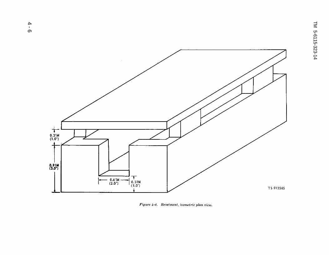
Figure 4-3.
TM 5-6115-323-14
4-
6

Figure 4-4.
TM
5-6115-323-14
4-
7

Figure 4-5.
TM
5
-61
15
-32
3-1
4
4-
8

Figure 4-6.
TM 5-6115-323-14
4-
9

Figure 4-7.
TM
5
-61
15
-32
3-1
4
4-1
0

TM 5-6115-323-14
ment. In addition, the generator end will be h. Multiple Installations. No more than onetowards the doorway. These instructions are veryimportant and must be observed to obtain max-
generator set will be installed within each revet.
imum ventilation and cooling benefits whenment Also, no other heat generating equipmentwill be placed in the revetment with a generator
operating in a revetment. set.
Section Il. MOVEMENT TO A NEW WORKSITE
4-5. Dismantling for Movement c. Fuel System. Remove the auxiliary fuel line,a. General. The generator set, being self-con- if used, and drain the fuel line. Drain the fuel
tained and Iightweigh, is readily portable. Discon- filter bowl.nect any exhaust piping which may have beeninstalled and remove all holddown bolts. Lift it at the four upper comers of the frame. If it is to be 4-6. Reinstallation After Movement
transported; block or tie it to the carrier to pre- Reinstall the generator set in the same mannervent damage by shifting during transit. as described in paragraph 4-2.
b. Load and Ground Cables. Refer to paragraph4-2d and disconnect load and ground cables.
Section Ill. REPAIR PARTS, SPECIAL TOOLS, SPECIAL TEST, MEASUREMENT AND DIAGNOSTICEQUIPMENT (TMDE), AND SPECIAL SUPPORT EQUIPMENT
4-7. Tools and Equipment 4-8. Maintenance Repair Parts (A)
No special tools or equipment are required to Repair parts and equipment are listed and illus-perform organizational maintenance on the gen- trated in the repair parts and special tools listerator set. manual covering organizational maintenance (See
A p p e n d i x A).
Section IV. PREVENTIVE MAINTENANCE CHECKS AND SERVICES (PMCS)
4-9. General
To insure that the generator set is ready foroperation at all times, it must be inspected sys-tematically so that defects may be discovered andcorrected before they result in serious damage orfailure. The necessary preventive maintenaceservices to be performed are listed and describedin paragraphs 3-4 and 4-10. Item numbers indi-cate the sequence of minimum inspection require-ments. Defects discovered during operation of theunit shall be noted for future correction, to bemade us soon as operation has ceased. Stop opera-tion immediately if a deficiency is noticed whichwould damage the equipment if operation werecontinued. Air Force users shall refer to the appli-cable inspection manuals and work card sets in
T.O. 35C2-3-1-426 Series for periodicmaintenance requirements and Tabletailed procedures.
preventive4-1 for de-
4-10. Preventive Maintenance Checks andservices
The preventive maintenance checks and servicesto be performed are in Table 4-1. This table showsthe inspection that must be performed by organiza-tional personnel. The item numbers are listed con-secutively and indicate the sequence of minimumrequirements. Refer to Table 4-1 for checks andservices.
Change 2 4-11

TM 5-6115-323-14
Table 4-1. Organizational Preventive Maintenance Checks and Services
W - weekly (40 hours) S - Semiannually (500 hours)M - Monthly (100 hours) H – Hours (as indicated)
PROCEDURES EQUIPMENTITEM INTERVAL ITEM CHECK FOR AND HAVE IS NOT READYNO. INSPECTED REPAIRED OR ADJUSTED AVAILABLE
W H AS NECESSARY
1 50 Lubricating Oil Change oil every 50 hours ofoperation.
2 50 Fuel Filter Inspect fuel filter every 50 hoursof operation. Clean as necessary(para 4-17 and Fig. 4-7, TM 5-2805-257-14).
Section V. Troubleshooting
4-11. General
This section contains troublshooting or mal-function infornmtion and tests for locating andcorrecting meet of the troubles which may developin the generator sets. Each malfunction or troublesymptom for an individual component unit orsystem is followed by a list of test or inpectionsnecessary for you to determine probable causesand suggested corrective actions for you to rem-edy the malfunction.
4-12. Troubleshooting
a. This manual cannot list all possible malfunc-tions that may occur or all tests or inspections,and corrective actions. If a malfunction is notlisted (except when malfunction and cause areobvious), or is not corrected by listed correctiveactions you should notify higher Ievel mainte-nance
b. Table 4-2 lists the common malfunction thatyou may find during the operation or mainte-nance of the generator sets or their components.You should perform the test/inpections and cor-rective actions in the order listed.
NOTEBefore you use this table, be sure you have per-formed all normal operational checks. If you havea malfunction which is not Iisted in this table,notify the next higher level of maintenance.
Air Force Users may perform maintenance withinthe scope of their capabilities.
Table 4-2. Troubleshooting
MALFUNCTIONTEST OR INSPECTION
CORRECTIVE ACTION
1. ENGINE FAILS TO START OR MAL-FUNCTIONSInspect the engine for electrical or mechanical failure.
refer to the appropriate service manual inAppendix A.
2. NO OUTPUT VOLTAGE SHOWN B YVOLTMETERStep 1 Inspect the voltmeter for signs of burning,
broken or cracked glass, water or other dam- age. Test the voltmeter as follows:
Voltmeter (Ac Unit) a. Remove load cables from load terminals.b. Start the generator set.c. Position load switch to ON position.d. With a multimeter measure the output
voltage across the load terminals to verify voltage on the set voltmeter should not vary more than 9%
Voltmeter (DC Unit)a. Remove load cables from load terminals.b. Start the generator set.
4-12 Change 8

Table 4–2. TROUBLESHOOTING – Continued
MALFUNCTIONTEST OR INSPECTION
CORRECTIVE ACTION
2. NO OUTPUT VOLTAGE SHOWN BYVOLTMETER—Continued
c. Position the circuit breaker to the ONposition.d. With a multimeter, measure the outputvoltage across load terminals to verify thevoltage on the set voltmeter. Voltage shouldnot vary more than 4 volts.If voltage variation exceeds 5%, replace thevoltmeter (AC Unit) (para 4-25). If voltagevariation exceeds 4 volts, then replace thevoltmeter (DC Unit) (para 4-26).
Step 2. Inspect the voltage changeover toggle switch(AC Unit) for proper operation, signs of burn-ing, loose wire contacts, stripped threads, andother damage. Test the voltage changeovertoggle switch as follows:
a. With the power off, disconnect the volt-age changeover switch.
b. Position switch on 120 V setting andcheck continuity between the center terminaland the 120 V terminal.
c. Position switch on 240 V setting andcheck continuity between the center terminaland the 240 V terminal.If a malfunction is indicated on either posi–tion, replace the switch (para 4-25).
Step 3. Inspect the terminal boards for cracks orburned areas.Replace defective terminal boards (paras 4-25 and 4-26).
Step 4. Inspect the load switch (AC Unit), for properoperation, signs of burning, loose wire con-tacts, stripped threads, or other damage. Testthe load switch as follows:
a. Stop generator set and disconnect termi-nals to load switch.
b. With a multimeter, check the continuityof the load switch. OFF position will indicatean open circuit; ON position will indicate ashort circuit.
TM 5-6115-323-14TO 35C2-3-385-l
Table 4-2. TROUBLESHOOTING - Continued
MALFUNCTIONTEST OR INSPECTION
CORRECTIVE ACTION
2. NO OUTPUT VOLTAGE SHOWN BYVOLTMETER—Continued
If the above readings are not obtained, re-place the load switch (para 4-25).
Step 5. Manually flash the fields as follows:a. Connect two 1.5 volt flashlight batteries
in series and connect a wire to each end.b. Connect the positive wire from the
batteries to terminal No. 5 on the voltageregulator.
c. Start the generator set.d. Momentarily touch the negative wire to
terminal No. 6 on the voltage regulator toflash the field.If the field cannot be flashed, refer to inter-mediate (field), (direct support and generalsupport) maintenance personnel.
Step 6 Inspect the shunt (DC Unit) for burnt areasand other damage.Replace a defective shunt (para 4-26).
3. OUTPUT VOLTAGE SHOWN ON VOLT-METER AS HIGH OR LOW
Step 1.
Step 2.
Inspect the voltmeter for signs of burning,broken or cracked glass, water or other dam-age. Test the voltmeter. (See Malfunction 2,Step 1.)Replace a defective voltmeter (paras 4-25and 4-26).
Inspect the ground strap for burned areas,frayed spots, broken strands, loose connectors,and other damage.Replace a defective ground strap (para 4-19).
4. FREQUENCY NOT SHOWN ON FRE-QUENCY METER OR CANNOT BE STA-BILIZED AT 60 HZ (AC Unit).
Inspect the frequency meter for signs of burning bro-ken or cracked glass, water or other damage.
Replace a defective frequency meter (para 4-25).
Sect ion VI . RADIO INTERFERENCE SUPPRESSION4-13. General Methods Used to Attain Proper 4-14. Interference Suppression Components
Suppression The generator set is not provided with any primary
Essentially, suppression is attained by providing a radio interference components that are the responsibility
low-resistance path to ground for stray currents. The of organizational maintenance. For information covering
methods used include shielding the ignition and high secondary radio interference components on the engine,
frequency wires, grounding the frame with bonding refer to the appropriate engine manual in Appendix A.
straps, and using capacitors and resistors. For generalinformation on radio interference suppression, seeAppendix A for the appropriate service manual.
4–13

TM 5-6115-323-14TO 35C2-3-385-1
Section VII. MAINTENANCE OF THE ENGINE ASSEMBLY
4-15. General
The engine of the generator set is provided with anexhaust extension that directs the flow of exhaustgases in a direction away from the engine and theframe of the generator set. This section provides in–structions for maintenance of the exhaust extensionthat are the responsibility of organizationalmaintenance personnel.
4-16. Exhaust Extension
a. Removal. Refer to figure 4-8 and remove the ex-haust extension.
b. Cleaning and Inspection.
(1) Clean and dry the exhaust extension and at-taching hardware thoroughly.
(2) Inspect the exhaust extension for cracks,breaks. distortion. and excessive rust.
(3) Inspect the gasket for breaks, burnedthrough spots and other signs of failure.
(4) Replace defective parts.c. Installation. Refer to figure 4–8 and install the
exhaust extension.
CAUTIONThe United States Forestry Service
requires that any engine driven equipmentoperating within National Forests or Parksbe provided with spark arrestors for theavoidance of forest fires.
GASKET EXHAUST MANIFOLD MUFFLER
EXHAUST EXTENSION
Figure 4-8. Exhaust extension, removal and installation.d. Spark Arrestor. When a spark arrester is required,
the installation procedure will be on the instruction sheetfurnished with the spark arrester kit located on page B–2.
Section VIII MAINTENANCE OF THE FRAME ASSEMBLY
4-17. GeneralThe frame assembly of the generator set consists of
the frame, rails, shock mounts, ground terminal andground strap. This section provides instructions formaintenance of the ground terminal and ground strapthat are the responsibility of organizationalmaintenance personnel.
4-18. Ground Terminal
a. Removal. Refer to figure 4–9 and remove theground terminal.
b. Cleaning and Inspection.
(1) Clean and dry the ground terminalthoroughly
(2) Inspect the ground terminal for evidence ofburning and for cracks, damaged threads, and otherdamage.
(3) Replace a defective ground terminal.(4) Replace lost or broken terminal clip (retainer,
safety clip). For fabrication procedures, see Chapter
4, Section X Maintenance of the Control BoxAssembly, paragraph 4-27.
REMOVE NUTAND WASHER
Figure 4–9. Ground terminal, removal and installation.
4 - 1 4 Change 9

TM 5-6115-323-14TO 35C2-3-385-1
(3) Replacc defective ground terminal.(4) Replace lost or broken terminal clip(retainer,
safety clip). For fabrication procedures, see Chapter 4,Section X Maintenance of the Control Box Assembly,paragraph 4-27.
c. Installation. Refer to figure 4–9 and installthe ground terminal.
4-19. Ground Strapa. Removal. Refer to figure 4–10 and remove the
ground strap.
b. Cleaning and Inspection.
(1) Clean and dry the ground strap thoroughly.(2) Inspect the ground strap for burncd areas,
frayed spots, broken strands, loose connectors,and other damage.
(3) Replace a defective ground strap.c. Installation. Refer to figure 4–10 and install
the ground strap.
Figure 4–10. Ground strap, removal and installation.
(2) Inspect the ground terminal for evidence ofburning and for cracks, damaged threads, and otherdamage.
Section IX. MAINTENANCE OF THE FUEL SYSTEM
4-20. General (1) Thoroughly clean and dry all parts.
Thc generator set is provided with an on–set (2) Inspect the hose for cracks and for afuel tank. Fuel from the tank flows, by means of a frayed cover. Inspect the fittings on the ends forhose and the necessary fittings and adapters, to cracks and damaged threads.the fuel selector valve. The fuel selector valve and (3) Inspect the fuel selector valve for cracks,fuel filter are both mounted directly on the engine distortion, damaged threads, and other damage.fuel pump by means of a pipe nipple. All of the (4) Inspect the fuel filter for cracks and dam-generator sets that have been manufactured on aged threads. Inspect the bowl for chipped areas,or before May 1969 have been equipped with especially at the top seating surface. Inspect forstainless steel fuel tanks. Some subsequent sets cracks in the side of the bowl. Inspect the bowl forhave nylon fuel tanks and a different mounting distortion.arrangement. If replacement of a steel tank is (5) Replacec all damaged or defective parts.required, replace with a nylon tank (NSN 2910–00-401-4264).
c. Installation. Refer to figure 4–11 and installfuel selector valve, fuel filtcr, and hose.
4-21. Fuel Selector Valve, Fuel Filter, and 4-22. Fuel Tank and Bracket (stainless SteelHose Tank)
a. Removal. Refer to figure 4-11 and remove the a. Removal.fuel selector valve, fuel filter and hose.
(1) Disconnect the fuel hose (para 4-21).b. Cleaning and Inspection.
Change 9 4-15

Figure 4-11.
Figure 4-11.
TM 5-6115-323-14TO 35C2-3-385-1
(2) Refer to figure 4-12 and remove the fuel b. Cleaning and Inspectiontank. (1) Clean and dry the fuel tank thoroughly.
(3) Refer to figure 4-13 and remove thebracket.
(2) Inspect the fueI tank for distortion, dents,cracks, damaged threads, and broken welds.
4-16 Change 9

Figure 4-12. Fuel tank, removal and installation (stainlesssteel tank).
TM 5-6115-323-14
(3) Make a particularly close inspection of thewelds that secure the hangar brackets to the sides ofthe tanks.
(4) Inspect the fuel tank bracket for cracks anddistortion.
5) Replace defective parts.
(6) If the steel fuel tank is defective, replace withnylon fuel tank (NSN 2910-00-401-4264).
c. Installation. Refer to figure 4-13 and install thefuel tank bracket.
4-23. Fuel Tank and Bracket (Nylon Tank)
NOTE
In order to avoid exertion due to excessiveforce on the fittings of a fuel tank, recom-mend using two wrenches to loosen/tightenthe fitting; one for holding the fitting andthe other for turning the plug.
a. Removal.
(1) Disconnect the fuel hose (fig. 4-14).
(2) Refer to figures 4-14, 4-15, and 4-16 andremove the fuel tank and bracket.
b. Cleaning and Inspection.
(1)
(2)areas.
(3)
(4)
Clean and dry the fuel tank carefully.
Inspect the fuel tank for abraided or gouged
Inspect for cracks.
Inspect the outlet opening or hole to see thatit is not stripped out. This opening was not original-ly threaded, but was left blank so that a fitting, wheninstalled, would form its own thread in the relativelysoft nylon.
(5) Inspect the straps and brackets for cracksand breaks.
(6) Replace all defective parts.
c. Installation.
(1) Refer to figures 4-14,4-15, and 4-16 and in-stall the fuel tank and brackets.
(2) Connect the fuel hose (fig. 4-14).
Change 5 4-17

TM 5-6115-323-14
Figure 4-13. Fuel tank bracket, removal and installation (stainless steel tank).
4-18
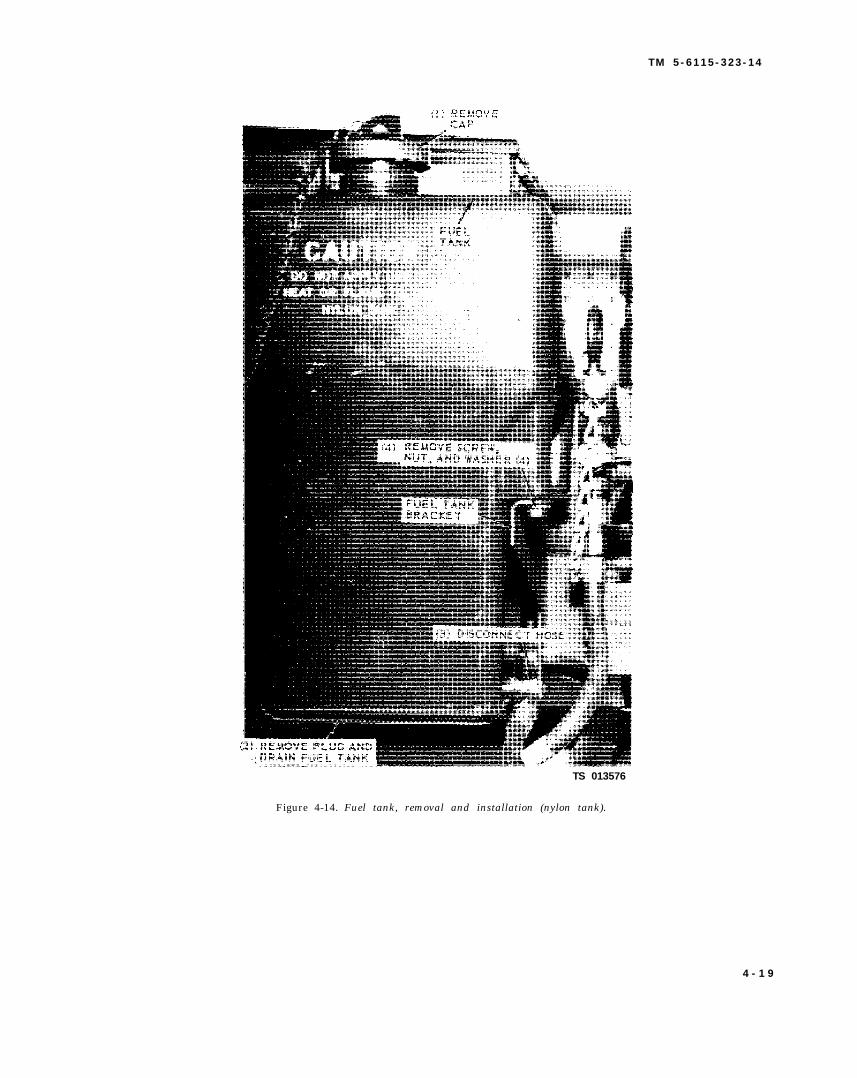
T M 5 - 6 1 1 5 - 3 2 3 - 1 4
TS 013576
Figure 4-14. Fuel tank, removal and installation (nylon tank).
4 - 1 9
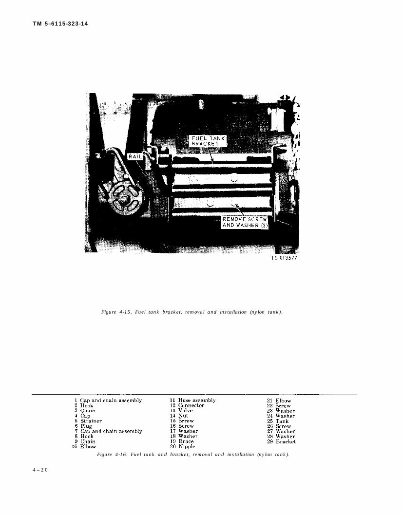
TM 5–6115-323-14
Figure 4-15. Fuel tank bracket, removal and installation (nylon tank).
Figure 4-16. Fuel tank and bracket, removal and installation (nylon tank).
4 – 2 0

Figure 4-16
Figure 4-16
TM
5-6115-323-14
4-21

TM 5-6115-323-14
Section X. MAINTENANCE OF THE CONTROL BOX ASSEMBLY
4-24. General
The generator sets, both the AC and DC units,are each equipped with a control box mountedover the generator. They provide a housing forthe components required to control the electricalfunctions of the generator and they provide amounting point for the operator’s controls andinstruments and the power output terminals. Thecontrol boxes are similar in general appearanceand function. However, several of the components,within, differ between the two units. Also, the ACunit control box contains several more compo-nents than is contained in the DC units. Thecomponents within the two control boxes that arethe responsibility of organizational maintenanceare covered separately, for the AC and DC units,by paragraphs in this section.
4-25. Control Box Components (AC Unit)
a. Test. Test the AC control box components asfollows:
(1) Voltmeter.(a) Remove load cables from load terminals.(b) Start the generator set.(c) Position load switch to ON position.(d) With a multimeter, measure the output
voltage across the load terminals to verify voltageon the set voltmeter. Voltage should not varymore than 5%.
(e) If voltage variation exceeds 5%, replacethe voltmeter.
(2) Voltage Changeover Switch.(a) With the power off, disconnect the volt-
age changeover switch.(b) Position switch on 120 V setting and
check continuity between the center terminal andthe 120 V terminal.
(c) Position switch on 240 V setting andcheck continuity between the center terminal andthe 240 V terminal.
(d) If a malfunctioning open circuit is indi-cated on either position, replace the switch.
(3) Load Switch.(a) Stop generator set and disconnect termi-
nals to load switch.(b) With a multimeter, check the continuity
of the load switch. OFF position will indicate anopen circuit; ON position will indicate a shortcircuit.
(c) If the above readings are not obtained,replace the load switch.
b. Removal. Refer to figure 4-17 and remove thecontrol box components.
c. Cleaning and Inspection.(1) Clean all parts thoroughly.(2) Inspect the variable resistor knob for
cracks and stripped thread.(3) Inspect the voltmeter and frequency me-
ter for signs of burning, broken or cracked glass,water damage, and other damage.
(4) Inspect the terminal boards for cracks andburned areas.
(5) Inspect the load and voltage changeovertoggle switches for proper operation, signs ofburning, loose wire contacts, stripped threads, andother damage.
(6) Inspect the receptacle connector for looseconnections, signs of burning and other damage.
(7) Replace all defective parts.
d. Installation. Refer to figure 4-17 and installthe control box components.
4-26. Control Box Components (DC Unit)
a. Test. Test the DC control box components asfollows:
(1) Voltmeter.
(a) Remove load cables from load terminals.(b) Start the generator set.(c) Position the circuit breaker to the ON
position.(d) With a multimeter, measure the output
voltage across load terminals to verify the voltageon the set voltmeter. Voltage should not varymore than 4 volts.
(e) If voltage variation exceeds 4 volts, thenreplace the voltmeter.
(2) Load Meter.,(a) Connect a load of known wattage and
proper voltage output terminals of the generatorset. Maximum load is 1500 watts.
(b) Start the generator and place circuitbreaker in ON position. Observe the reading onthe set load meter. Meter should indicate accord-ing to the load attached, i.e., 375 watts-25%; 750watts-50%, etc.
(c) If the load meter does not read withinspecifications, replace it.
4-22 Change 1

TM 5-6115-323-14
Figure 4-17. Control box conponents, removal and installation (AC Unit).
b. Removal. Refer to figure 4-18 and remove the (3) Inspect the voltmeter, loadmeter and am-control box components. meter for broken, missing, or cracked glass, signs
c. Cleaning and Inspection.of burning, water or moisture damage, strippedthreads, and other damage.
(1) Clean all parts thoroughly.(2) Inspect the variable resistor knob for (4) Inspect the terminal boards and terminal
cracks and stripped threads. load insulator for cracks and burned areas.
4-23

TM 5-6115-323-14
Figure 4-18. Control box components removal and installation (DC Unit).
(5) Inspect the shunt for burnt areas and d. Installation. Refer to figure 4-18 and installother damage. the control boxs components.
(6) Replace all defective parts.
4-24 Change 1

TM 5-6115-323-14
4-27. Replace Lost or Broken Terminal Clip(Retainer, Safety Clip)
The terminal clip is a component of both the loadterminal and the ground terminal. If the terminal clipis lost or broken, fabricate as follows: Requisition bulkwire as stated in the chart. Cut off about 3 inches ofthe wire. Cut the wire short enough to keep the clipsfrom touching another terminal or the generatorframe in the open or closed position. Slip the wirethrough the hole in the terminal and proceed as shownin the views below:
NSN 9505- 1 MEP-015AI MEP-025A
00-804-3814 Load Ground(0.042 inch) Ground
I 01-049-0144 I I Load(0.050 inch)
BULK WIRE CHART
Change 5 4-25/(4-26 blank)


TM 5-6115-323-14
CHAPTER 5
INTERMEDIATE (FIELD), (DIRECT SUPPORT AND GENERAL SUPPORT) AND DEPOTMAINTENANCE INSTRUCTIONS
Section l. REPAIR PARTS, SPECIAL TOOLS AND EQUIPMENT
5-1. Tools and Equipment 5-2. Intermediate (Field) (Direct Support and
The special tool required for intermediate (field), General Support) and Depot Maintenance(direct support and general support) and depot Repair Parts and Special Toolsmaintenance is listed in Table 5-1. Intermediate (field) (direct support and general
support) and depot maintenance repair parts arelisted and illustrated in the appropriate generatormanuals (See Appendix A). Parts applicable to theengine are listed and illustrated in the appropri-ate engine manuals (See Appendix A).
Table 5-1. Special Tools, Test, and Support Equipment (Including Fabricated Items)
5-1

5-2C
hange 4
Figure 5-1.
TM
5-6115-323-14

TM 5-6115-323-14
Section Il. TROUBLESHOOTING
5-3. General
This section contains troubleshooting or malfunc-tion information and tests for locating and correctingmost of the troubles which may develop in the genera-tor sets. Each malfunction or trouble symptom for anindividual component, unit, or system is followed by alist of test or inspections necessary for you to deter-mine probable causes and suggested corrective actionsfor you to remedy the malfunction.
5-4. Troubleshooting
a. This manual cannot list all possible malfunc-tions that may occur or all tests or inspections, andcorrective actions. If a malfunction is not listed(except when malfunction and cause are obvious), or isnot corrected by listed corrective actions, you shouldnotify higher level maintenance.
b. Table 5-2 lists the common malfunctions thatyou may find during the operation or maintenance ofthe generator sets or their components. You shouldperform the tests/inspections and corrective actions inthe order listed.
NOTEBefore you use this table, be sure you haveperformed all normal operational checks. Ifyou have a malfunction which is not listedin this table, notify the next higher level ofmaintenance. Air force users may performmaintenance within the scope of their capa-bilities.
Table 5-2. TROUBLESHOOTINGMALFUNCTION
TEST OR INSPECTIONCORRECTIVE ACTION
1.
2.
ENGINE FAILS TO START OR MALFUNC-TIONSInspect the engine for an electrical or mechanicalfailure.
Refer to the appropriate service manual(See Appendix A).
GENERATOR FAILS TO BUILD UP RATEDVOLTAGEStep 1. Manually flash the field as follows:
(1) Connect two 1.5 volt flashlightbatteries in series and connect a wire toeach end.
(2) Connect the positive wire fromthe batteries to terminal No. 5 on thevoltage regulator.
(3) Start the generator set.
Table 5-2. TROUBLESHOOTING - ContinuedMALFUNCTION
TEST OR INSPECTIONCORRECTIVE ACTION
2. GENERATOR FAILS TO BUILD UP RATEDVOLTAGE-Continued
Step 2.
(4) Momentarily touch the negativewire to terminal No. 6 on the voltageregulator to flash the field.If the field cannot be flashed, proceed toStep 2.Inspect the voltage regulator for cracks,signs of overheating and other damage.Test the voltage regulator as follows:
(1) Voltage Regulator (AC Unit).(a) Select desired voltage setting
on the voltage changeover switch ( 120 Vor 240 V) and start the generator set.Load cables should not be attached tothe output terminals.
(b) Using a multimeter, checkvoltage across output terminals to verifyreading on set voltmeter. If the votage islow and adjustment of the variable resis-tor will not correct the deficiency, checkthe exciter voltage across terminals 5 or6 of the voltage regulator. This voltagewill vary, but should be about 25 voltsDC. If no voltage appears on the regula-tor terminals, the voltage regulator isdefective and should be replaced.
(c) If voltage across regulator ter-minals 5 and 6 is satisfactory, stop thegenerator set, attach the load cables, andrestart the set.
(2) Voltage Regulator (DC Unit).(a) Disconnect load cables and
start generator set.(b) Trip the circuit breaker to
“ON” position, and observe reading onset voltmeter.
(c) Using a multimeter, check thevoltage across the output terminals toverify the reading on the set voltmeter. Ifthe voltage is low and adjustment of thevariable resistor will not correct the defi-ciency, check the exciter voltage acrossterminals 5 and 6 of the voltage regula-tor. This voltage will vary but should beabout 25 volts DC. If no voltage appearson the regulator terminals the voltageregulator is defective and should bereplaced.
Change 8 5-3
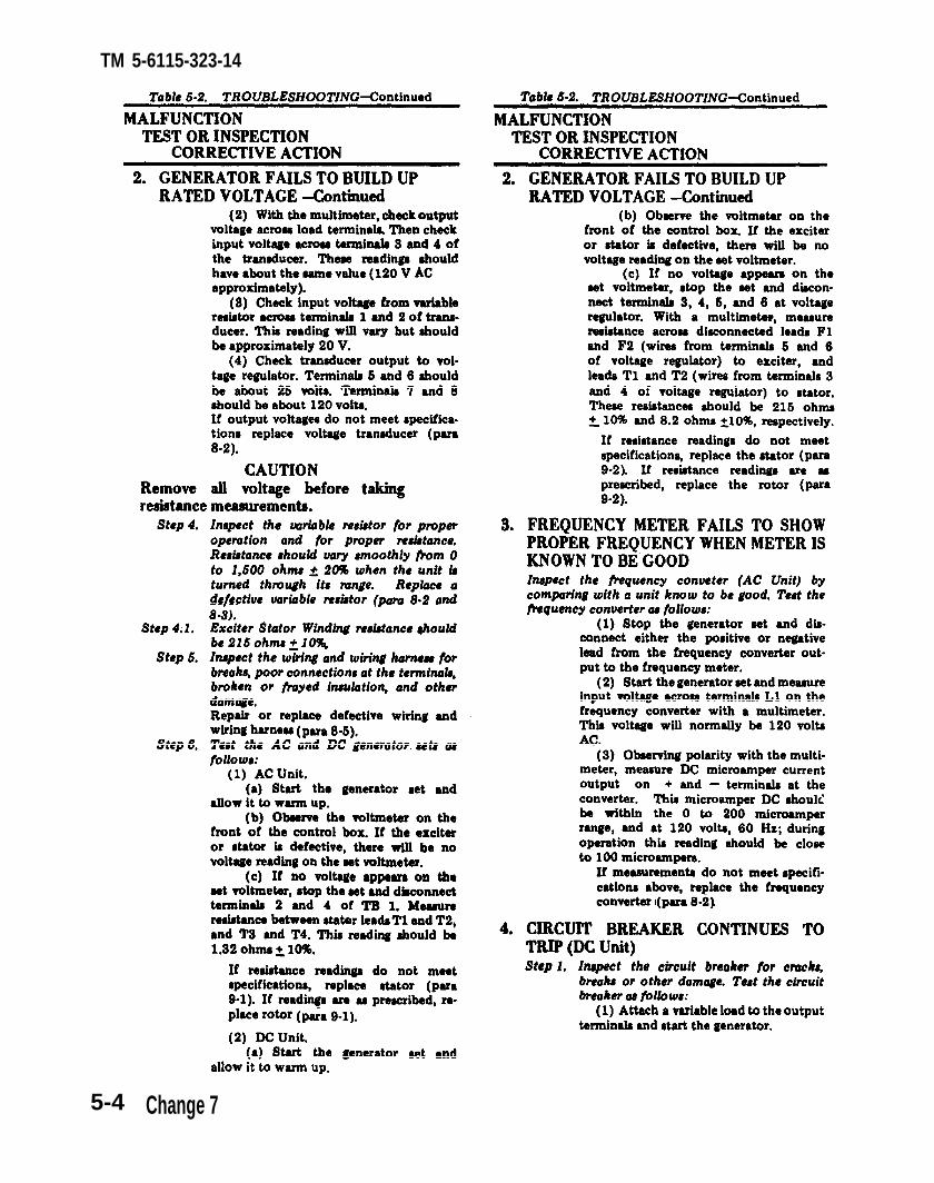
Table 5-2. Table 5-2.
para 9-2.
para 8-2.para 9-2.
para 8-2para 8-3.
para 8-5.
para 9-1.
para 8-2
TM 5-6115-323-14
5-4 Change 7

Table 5-2.
para 8-3
para 8-3
para 8-5
paras 8-2 and 8-3
para 8-2
para 8-2
para 8-5
para 9-1
para 9-1
para 9-1
para 9-1
para 8-2
(para 9-1 and 9-2)
(para 9-1 and 9-2)
Table 5-2
TM 5-6115-323-14
Section Ill. GENERAL MAINTENANCE
The maintenance to be performed by intermediate the furnished cutting and welding torch outfit or(fields), (direct support and general support) and by replacement. The wiring harness is repaired bydepot maintenance personnel on this equipment is soldering and wrapping with electrical tape. Thelimited to repair of the frame, wiring harness, and repair of the generator housing assembly is ac-the generator housing assembly. Repair is accom- complished by straightening, knocking out dents,plished on the frame by straightening bends using welding or replacement.
Change 1 5-5/(5-6 Blank)


TM 5-6115-323-14TO 35C2-3-385-1
CHAPTER 6
REMOVAL/INSTALLATION OF MAJOR COMPONENTS
Section I. GENERAL
This chapter contains removal and installation in– jor components are the engine, the control boxstructions for the major components. The three ma– assembly and the generator.
Section II. ENGINE6-1. Engine
a. Removal.
(1) Remove the winterization hose from theengine (See military standard engine manual TM5-2805-257-24P, Appendix A).
(2) Remove the generator (para 6-4 and 6-5).(3) Refer to figure 6-1 and remove the engine.
b. Installation.
(1) Refer to figure 6-1 and install the engine.(2) Install the generator (para 6-4 and 6-5).(3) Install the winterization hose on the engine
(See military standard engine manual TM5-2805-257-24P, Appendix A).
NOTE
When changing the spark plug cables, the engineend of the generator set must be elevated to haveaccess for removing the screws that are holding theengine flywheel fan cover (pull cover loose but letit remain in place). Refer to TM 5-2805-257-14,paragraph 4-40 for loosening of the flywheel fan.Remove both the flywheel fan and the flywheel fancover together, sliding both up between the engineand generator frame and lay on top of the engine.Referring to TM 5-2805-257-14, Figure 4-6,remove and replace the spark plug cables.Reassemble the engine in reverse procedure of theabove instructions.
ENGINE
RAIL REMOVE SCREW (6)AND WASHER (12)
Figure 6–1. Engine, removal and installation.
Section III. CONTROL BOX ASSEMBLY
6-2. General (2) Tag and disconnect the wire leads from the
All the controls and instruments necessary for theoperation of the generator are contained in the controlbox. These controls and instruments include thevoltage regulator, frequency converters, variableresistor, interference suppression components, ter–minal board, and the necessary wiring harness.
6-3. Control Box and Bracketa. Removal.
(1) Disconnect the ground strap at the generator (fig.4–l0).
generator at their connecting points inside the controlbox.
(3) Refer to figure 6-2 and remove the controlbox and bracket.
b. Installation.
(1) Refer to figure 6-2 and install the control boxand bracket.
(2) Connect the tagged wire leads to the properpoints in the control box.
(3) Connect the ground strap at the generator(fig. 4-10).
Change 9 6 -1
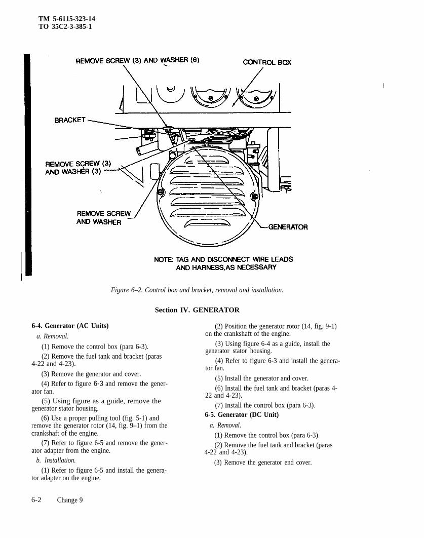
TM 5-6115-323-14TO 35C2-3-385-1
Figure 6–2. Control box and bracket, removal and installation.
Section IV. GENERATOR
6-4. Generator (AC Units)
a. Removal.
(1) Remove the control box (para 6-3).(2) Remove the fuel tank and bracket (paras
4-22 and 4-23).
(3) Remove the generator and cover.(4) Refer to figure 6-3 and remove the gener-
ator fan.(5) Using figure as a guide, remove the
generator stator housing.(6) Use a proper pulling tool (fig. 5-1) and
remove the generator rotor (14, fig. 9–1) from thecrankshaft of the engine.
(7) Refer to figure 6-5 and remove the gener-ator adapter from the engine.
b. Installation.
(1) Refer to figure 6-5 and install the genera-tor adapter on the engine.
(2) Position the generator rotor (14, fig. 9-1)on the crankshaft of the engine.
(3) Using figure 6-4 as a guide, install thegenerator stator housing.
(4) Refer to figure 6-3 and install the genera-tor fan.
(5) Install the generator and cover.(6) Install the fuel tank and bracket (paras 4-
22 and 4-23).(7) Install the control box (para 6-3).
6-5. Generator (DC Unit)
a. Removal.
(1) Remove the control box (para 6-3).(2) Remove the fuel tank and bracket (paras
4-22 and 4-23).
(3) Remove the generator end cover.
6-2 Change 9

Figure 6-3. Generator fan, removal and installation.
(4) Using figure 6-3 as agenerator fan.
(5) Remove the generator6-4).
TM 5-6115-323-14
guide, remove the
stator housing (fig.
(6) Remove the generator rotor(item 27, figure 9-2) using the properpulling tool ( figure 5-1). Insert
the 7-3/16 stud through center ofrotor and screw into end of crankshaft.Screw the bushing into rotor and tightenuntil rotor is free of crankshaft.
(7) Using figure 6-5 as a guide, remove thegenerator adapter from the engine.
b. Installation.(1) Using figure 6-5 as a guide, install the
generator adapter on the engine.(2) Position the generator rotor (27, fig. 9-2)
on the chankshaft of the engine.(3) Using figure 6-4 as a guide, install the
generator stator housing.(4) Refer to figure 6-3 and install the genera-
tor fan.(5) Install the generator end cover.(6) Install the fuel tank and bracket (para 4-
22 and 4-23).(7) Install the control box (para 6-3).
Figure 6–4. Generator stator housing, removal and installation.
Change 4 6–3

TM 5-6115-323-14
Figure 6–5. Generator adapter, removal and installation.
6-4

TM 5–6115-323-14
CHAPTER 7
MAINTENANCE OF THE FRAME ASSEMBLY
7-1. General
The frame serves as the mounting base for allcomponents of the generator set. In addition to itsuse as the base, its design is such that it affordsprotection for the components mounted within,and it provides an easy means of carrying the unitwhen movement is required. This paragraph pro-vides intermediate (field) (direct support and gen-eral support) and depot maintenance for theframe assembly.
7–2. Frame Assembly
a. Removal and Disassembly(1) Remove the engine (para 6-1) and genera-
tor (para 6-4 and 6-5).(2) Refer to figure 7-1 and disassemble the
frame.
b. Cleaning, Inspection, and Repair.(1) Clean all parts thoroughly.(2) Inspect the frame for distortion, cracks,
dents and broken welds.(3) Inspect the rails for cracks and elongated
holes.(4) Inspect the shock mounts for loose or
deteriorated inserts.(5) Repair the frame and rail as necessary by
straightening, using the cutting and weldingequipment.
(6) Replace an unrepairable frame or rail.(7) Replace all other defective parts.
c. Assembly and Installation.(1) Refer to figure 7-1 and assemble the
frame.(2) Install the engine (para 6-1) and genera-
tor (para 6-4 and 6-5).
7-1
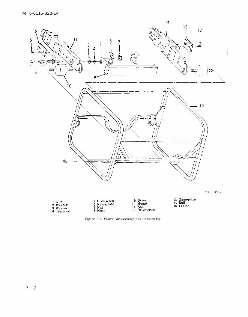
TM 5-6115-323-14
Figure 7-1. Frame, disassembly and reassembly.
7 - 2
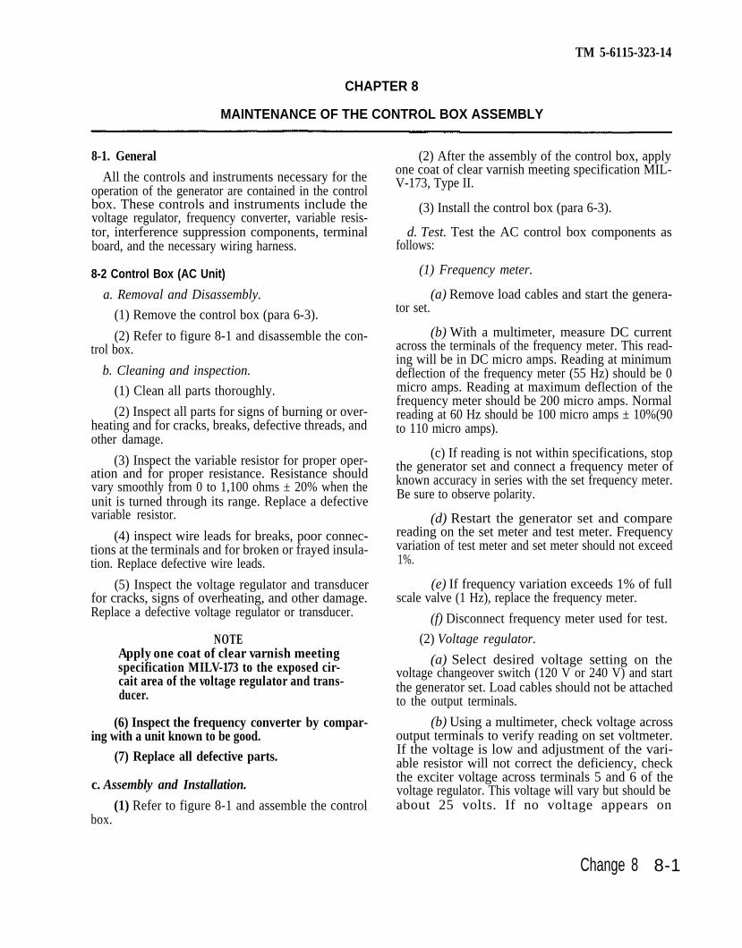
TM 5-6115-323-14
CHAPTER 8
MAINTENANCE OF THE CONTROL BOX ASSEMBLY
8-1. General
All the controls and instruments necessary for theoperation of the generator are contained in the controlbox. These controls and instruments include thevoltage regulator, frequency converter, variable resis-tor, interference suppression components, terminalboard, and the necessary wiring harness.
8-2 Control Box (AC Unit)
a. Removal and Disassembly.
(1) Remove the control box (para 6-3).
(2) Refer to figure 8-1 and disassemble the con-trol box.
b. Cleaning and inspection.
(1) Clean all parts thoroughly.
(2) Inspect all parts for signs of burning or over-heating and for cracks, breaks, defective threads, andother damage.
(3) Inspect the variable resistor for proper oper-ation and for proper resistance. Resistance shouldvary smoothly from 0 to 1,100 ohms ± 20% when theunit is turned through its range. Replace a defectivevariable resistor.
(4) inspect wire leads for breaks, poor connec-tions at the terminals and for broken or frayed insula-tion. Replace defective wire leads.
(5) Inspect the voltage regulator and transducerfor cracks, signs of overheating, and other damage.Replace a defective voltage regulator or transducer.
NOTEApply one coat of clear varnish meetingspecification MILV-173 to the exposed cir-cait area of the voltage regulator and trans-ducer.
(6) Inspect the frequency converter by compar-ing with a unit known to be good.
(7) Replace all defective parts.
c. Assembly and Installation.
(1) Refer to figure 8-1 and assemble the controlbox.
(2) After the assembly of the control box, applyone coat of clear varnish meeting specification MIL-V-173, Type II.
(3) Install the control box (para 6-3).
d. Test. Test the AC control box components asfollows:
(1) Frequency meter.
(a) Remove load cables and start the genera-tor set.
(b) With a multimeter, measure DC currentacross the terminals of the frequency meter. This read-ing will be in DC micro amps. Reading at minimumdeflection of the frequency meter (55 Hz) should be 0micro amps. Reading at maximum deflection of thefrequency meter should be 200 micro amps. Normalreading at 60 Hz should be 100 micro amps ± 10%(90to 110 micro amps).
(c) If reading is not within specifications, stopthe generator set and connect a frequency meter ofknown accuracy in series with the set frequency meter.Be sure to observe polarity.
(d) Restart the generator set and comparereading on the set meter and test meter. Frequencyvariation of test meter and set meter should not exceed1%.
(e) If frequency variation exceeds 1% of fullscale valve (1 Hz), replace the frequency meter.
(f) Disconnect frequency meter used for test.
(2) Voltage regulator.
(a) Select desired voltage setting on thevoltage changeover switch (120 V or 240 V) and startthe generator set. Load cables should not be attachedto the output terminals.
(b) Using a multimeter, check voltage acrossoutput terminals to verify reading on set voltmeter.If the voltage is low and adjustment of the vari-able resistor will not correct the deficiency, checkthe exciter voltage across terminals 5 and 6 of thevoltage regulator. This voltage will vary but should beabout 25 volts. If no voltage appears on
Change 8 8-1

Figure 8-1.
Figure 8-1.
TM 3-6115-323-14
8-2

Figure 8-1-Continued.
Figure 8-1
TM 5–6115-323-14
the regulator terminals, the voltage regulator isdefective and should be replaced.
(c) If voltage across regulator terminals 5and 6 is satisfactory, stop the generator set, at-tach the load cables, and restart the set.
(d) If voltage is still not satisfactory replacethe voltage regulator and repeat steps (a) thru (d).
(3) Transducer.(a) Disconnect load cables and start genera-
tor set.(b) With the multimeter, check output volt-
age across load terminals. Then check input volt-age across terminals 3 and 4 of the transducer.These readings should have about the same value(120 V approximately).
(c) Check input voltage from variable resis-tor across terminals 1 and 2 of transducer. Thisreading will vary but should be approximately 20v.
(d) Check transducer output to voltage reg-ulator. Terminals 5 and 6 should be about 120 V.Terminals 7 and 8 should be about 25 volts.
(e) If output voltages do not meet specifica-tions, replace voltage transducer.
(4) Capacitor (noise suppression).NOTE
The only accurate way to test a capacitor is byputting it on a capacitor testor. However, you cantell if a capacitor is working by the followingmethod.
(a) Stop the generator and disconnect thelead-in terminal to the capacitor.
(b) With the multimeter on ohms setting,touch test probes to input terminal and capacitormetal case, then reverse the probes. The multime-ter will give a momentary reading then fall backto zero.
the(c) If this reading does not occur, replace
capacitor.(5) Frequency converter.
(a) Stop the generator set and disconnecteither the positive or negative lead from thefrequency converter output to the frequency me-ter.
(b) Start the generator set and measureinput voltage across terminals L1 on the fre-quency converter with a multimeter. This voltagewill normally be 120 volts AC.
(c) Observing polarity with the multimeter,measure DC microampher current output on +and – terminals at the converter. This microam-pher DC should be within the 0 to 200 microam-pher range, and at 120 volts, 60 Hz, during opera-tion this reading should be close to 100 microam-pher.
(d) If measurements do not meet specifica-tions above, replace the frequency converter.
(6) Variable resistor (AC).(a) Stop generator set and disconnect termi-
nal 5 of TB 1 (fig. 1-5).(b) Insert multimeter probes to this discon-
nected wire and terminal 6 in TB 1 (fig. 1–5). Withthe variable resistor in the full counterclockwiseposition slowly turn the control knob to the fullclockwise position. This reading should movesmoothly from 0 to 1100 ohms A 20%, as thevariable resistor is rotated to the full clockwiseposition.
(c) If the reading is not within specifica-tions, replace the variable resistor.
8-3. Control Box (DC Unit)
a. Removal and Disassembly.(1) Remove the control box (para 6-3).(2) Refer to figure 8-2 and disassemble the
control box.b. Cleaning and Inspection.
(1) Clean all parts thoroughly.(2) Inspect all parts for signs of burning or
8–3

Figure 8-2.
Figure 8-2.
TM
5-6115-323-14
8-4
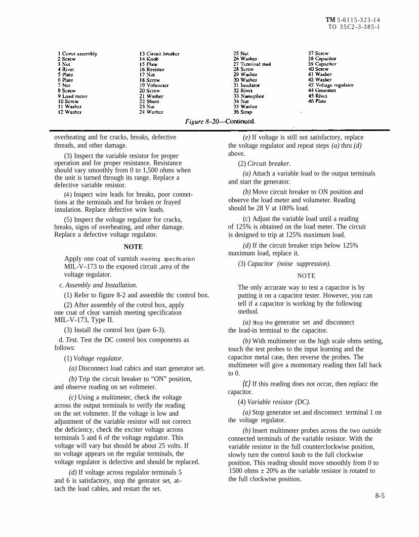
Figure 8-20-Continued.
Figure 8-20
TM 5-6115-323-14TO 35C2–3-385-1
overheating and for cracks, breaks, defectivethreads, and other damage.
(3) Inspect the variable resistor for properoperation and for proper resistance. Resistanceshould vary smoothly from 0 to 1,500 ohms whenthe unit is turned through its range. Replace adefective variable resistor.
(4) Inspect wire leads for breaks, poor connet-tions at the terminals and for broken or frayedinsulation. Replace defective wire leads.
(5) Inspect the voltage regulator for cracks,breaks, signs of overheating, and other damage.Replace a defective voltage regulator.
NOTE
Apply one coat of varnish meeting specification
MIL-V–173 to the exposed circuit ,area of thevoltage regulator.
c. Assembly and Installation.
(1) Refer to figure 8-2 and assemble thc control box.(2) After assembly of the cotrol box, apply
one coat of clear varnish meeting specificationMIL-V-173, Type II.
(3) Install the control box (pare 6-3).d. Test. Test the DC control box components as
follows:
(1) Voltage regulator.(a) Disconnect load cabics and start generator set.
(b) Trip the circuit breaker to “ON” position,and observe reading on set voltmeter.
(c) Using a multimeter, check the voltageacross the output terminals to verify the readingon the set voltmeter. If the voltage is low andadjustment of the variable resistor will not correctthe deficiency, check the exciter voltage acrossterminals 5 and 6 of the voltage regulator. Thisvoltage will vary but should be about 25 volts. Ifno voltage appears on the regular terminals, thevoltage regulator is defective and should be replaced.
(d) If voltage across regulalor terminals 5and 6 is satisfactory, stop the genrator set, at–tach the load cables, and restart the set.
(e) If voltage is still not satisfactory, replacethe voltage regulator and repeat steps (a) thru (d)above.
(2) Circuit breaker.(a) Attach a variable load to the output terminals
and start the generator.
(b) Move circuit breaker to ON position andobserve the load meter and volumeter. Readingshould be 28 V at 100% load.
(c) Adjust the variable load until a readingof 125% is obtained on the load meter. The circuitis designed to trip at 125% maximum load.
(d) If the circuit breaker trips below 125%maximum load, replace it.
(3) Capacitor (noise suppression).
NOTE
The only accurate way to test a capacitor is byputting it on a capacitor tester. However, you cantell if a capacitor is working by the followingmethod.
(a) Stop the generator set and disconnectthe lead-in terminal to the capacitor.
(b) With multimeter on the high scale ohms setting,touch the test probes to the input learning and thecapacitor metal case, then reverse the probes. Themultimeter will give a momentary reading then fall backto 0.
(c) If this reading does not occur, then replacc thecapacitor.
(4) Variable resistor (DC).
(a) Stop generator set and disconnect terminal 1 onthe voltage regulator.
(b) Insert multimeter probes across the two outsideconnected terminals of the variable resistor. With thevariable resistor in the full counterclockwise position,slowly turn the control knob to the full clockwiseposition. This reading should move smoothly from 0 to1500 ohms ± 20% as the variable resistor is rotated tothe full clockwise position.
8-5

TM 5-6115-323-14TO 35C2-3-385-1
(c) If the reading is not within specifica-tions, then replace the variable resistor.
8-4. Radio Interference Suppressiona. General. This paragraph contains informa–
tion applicable to the primary suppression compo-nents that are the responsibility of intermediate(field), (direct support and general support), anddepot maintenance. For general information onradio interference suppression, refer to paragraph4-13. For radio interference suppression informa–tion that applies to the engines, refer to theappropriate service manual for engines (See Ap-pendix A).
b. Interference Suppression Components.
(1) AC Unit. The control box of the AC unit isequipped with two capacitors that are providedfor interference suppression. They are rated at 0.1MFD, 500 V, AC/DC. These capacitors are shownby figure 8-3.
(2) DC Unit. The DC Unit control box isequipped with two capacitors that providesuppression of radio interference. They are rated
at 0.5 MFD, 100 V DC. These capacitors are shownby figure 8-4.
c. Replacement of Suppression Components.
(1) AC Unit. For replacement of interference. .suppression components on the AC unit, refer tofigure 8–3.
(2) DC Unit. For replacement of interferencesuppression components on the DC unit, refer tofigure 8-4.
d. Testing of Radio Interference SuppressionComponents.
NOTE
The only accurate way to test a capacitor is byputting it on a capacitor tester. However, you cantell if a capacitor is working by the followingmethod.
(1) Stop the generator set and disconnect thelead-in terminal to the capacitor.
(2) With the multimeter on the high scaleohms setting, touch the test probes to the inputterminal and the capacitor metal case, then re-verse the probes. The multimeter will give amomentary reading, then fall back to 0.
Figure 8-3. Radio interference suppression components, removal and installation (AC Unit).
8-6 Change 9

Figure 8–4. Radio interference suppression components,removal and installation (DC Unit).
TM 5–6115-323-14
(3) If this reading does not occur, then replacethe capacitor.
8-5. Wiring Harness
a. Inpection. Inspect the wiring and wiring har-ness for breaks, poor connections at the terminals,broken or frayed insulation, and other damage.
b. Test. Test the wiring for continuity using amultimeter.
c. Repair.(1) Wrap slight insulation deterioration with
electrical tape.(2) Make soldering connections wherever pos-
sible.
d. Removal. Tag each wire and correspondingterminal to insure correct installation and re-placement.
e. Installation. Install wires in the reverse or-der of removal and remove all tags.
8-7

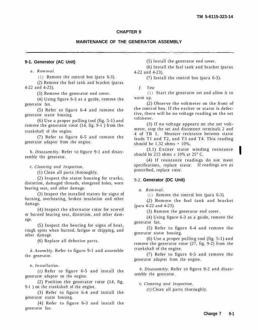
TM 5-6115-323-14
CHAPTER 9
MAINTENANCE OF THE GENERATOR ASSEMBLY
9-1. Generator (AC Unit)
a. Removal.(1) Remove the control box (para 6-3).(2) Remove the fuel tank and bracket (paras
4-22 and 4-23).(3) Remove the generator end cover.(4) Using figure 6-3 as a guide, remove the
generator fan.(5) Refer to figure 6-4 and remove the
generator stator housing.(6) Use a proper pulling tool (fig. 5-1) and
remove the generator rotor (14, fig. 9-1 ) from thecrankshaft of the engine.
(7) Refer to figure 6-5 and remove thegenerator adapter from the engine.
b. Disassembly. Refer to figure 9-1 and disas-semble the generator.
c. Cleaning and Inspection.(1) Clean all parts thoroughly.(2) Inspect the stator housing for cracks,
distortion, damaged threads, elongated holes, wornbearing seat, and other damage.
(3) Inspect the installed stators for signs ofburning, overheating, broken insulation and otherdamage.
(4) Inspect the alternator rotor for scoredor burned bearing seat, distortion, and other dam-age.
(5) Inspect the bearing for signs of heat,rough spots when burned, fatigue or chipping, andother damage.
(6) Replace all defective parts.
d. Assembly. Refer to figure 9-1 and assemblethe generator.
e. Installation.(1) Refer to figure 6-5 and install the
generator adapter on the engine.(2) Position the generator rotor (14, fig.
9-1 ) on the crankshaft of the engine.(3) Refer to figure 6-4 and install the
(5) Install the generator end cover.(6) Install the fuel tank and bracket (paras
4-22 and 4-23).(7) Install the control box (para 6-3).
f. Test(1) Start the generator set and allow it to
warm up.(2) Observe the voltmeter on the front of
the control box. If the exciter or stator is defec-tive, there will be no voltage reading on the setvoltmeter.
(3) If no voltage appears on the set volt-meter, stop the set and disconnect terminals 2 and4 of TB 1. Measure resistance between statorleads T1 and T2, and T3 and T4. This readingshould be 1.32 ohms + 10%.
(3.1) Exciter stator winding resistanceshould be 215 ohms ± 10% at 25° C.
(4) If resistance readings do not meetspecifications, replace stator. If readings are asprescribed, replace rotor.
9-2. Generator (DC Unit)
a. Removal.(1) Remove the control box (para 6-3).(2) Remove the fuel tank and bracket
(para 4-22 and 4-23).(3) Remove the generator end cover.(4) Using figure 6-3 as a guide, remove the
generator fan.(5) Refer to figure 6-4 and remove the
generator stator housing.(6) Use a proper pulling tool (fig. 5-1) and
remove the generator rotor (27, fig. 9-2) from thecrankshaft of the engine.
(7) Refer to figure 6-5 and remove thegenerator adapter from the engine.
b. Disassembly. Refer to figure 9-2 and disas-semble the generator.
c. Cleaning and Inspection.(1) Clean all parts thoroughly.
generator stator housing.(4) Refer to figure 6-3 and install the
generator fan.Change 7 9-1

Figure 9-1.
Figure 9-1.
TM
5
-61
15
-32
3-1
4
9-2
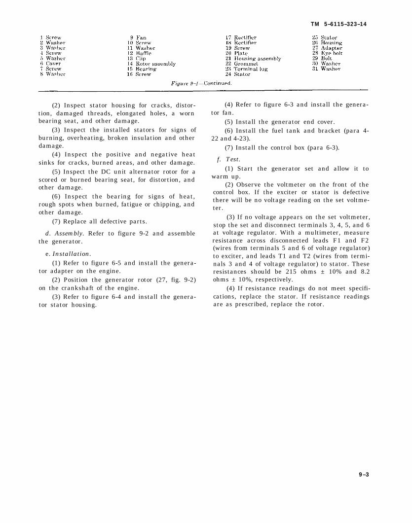
Figure 9-1 Continued.
Figure 9-1
TM 5–6115–323–14
(2) Inspect stator housing for cracks, distor-tion, damaged threads, elongated holes, a wornbearing seat, and other damage.
(3) Inspect the installed stators for signs ofburning, overheating, broken insulation and otherdamage.
(4) Inspect the positive and negative heatsinks for cracks, burned areas, and other damage.
(5) Inspect the DC unit alternator rotor for ascored or burned bearing seat, for distortion, andother damage.
(6) Inspect the bearing for signs of heat,rough spots when burned, fatigue or chipping, andother damage.
(7) Replace all defective parts.
d. Assembly. Refer to figure 9-2 and assemblethe generator.
e. Installation.(1) Refer to figure 6-5 and install the genera-
tor adapter on the engine.(2) Position the generator rotor (27, fig. 9-2)
on the crankshaft of the engine.(3) Refer to figure 6-4 and install the genera-
tor stator housing.
(4) Refer to figure 6-3 and install the genera-tor fan.
(5) Install the generator end cover.(6) Install the fuel tank and bracket (para 4-
22 and 4-23).(7) Install the control box (para 6-3).
f. Test.(1) Start the generator set and allow it to
warm up.(2) Observe the voltmeter on the front of the
control box. If the exciter or stator is defectivethere will be no voltage reading on the set voltme-ter.
(3) If no voltage appears on the set voltmeter,stop the set and disconnect terminals 3, 4, 5, and 6at voltage regulator. With a multimeter, measureresistance across disconnected leads F1 and F2(wires from terminals 5 and 6 of voltage regulator)to exciter, and leads T1 and T2 (wires from termi-nals 3 and 4 of voltage regulator) to stator. Theseresistances should be 215 ohms ± 10% and 8.2ohms ± 10%, respectively.
(4) If resistance readings do not meet specifi-cations, replace the stator. If resistance readingsare as prescribed, replace the rotor.
9–3
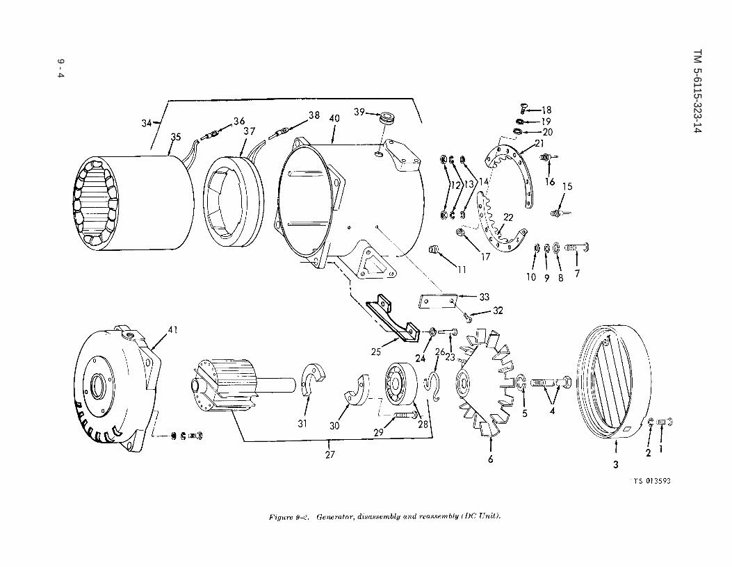
Figure 9-2.
Figure 9-2.
TM 5-6115-323-14
9-
4

Figure 9–2—Continued.
TM 5–6115-323-14
9 - 5


TM 5–6115-323-14
APPENDIX A
REFERENCES
This appendix contains a list of reference manuals that may be used in conjunction with this TM in theoperation and maintenance of the 1.5 KW DOD Generator. Those manuals not coded are applicable for useby all services. The manuals are coded (A), for Army use; and (F), for Air Force use.
A–1. Fire Protection
TB 5-4200-200-10
A–2. Lubrication
C9100-IL (A)LO 5-2805-257-12 (A)
TB 703-1 (A)
T.O. 35C2-3-1-426WC-3-5-1 (F)
A-3. Painting
AR 740-1 (A)AR 746-5 (A)T.O. 35-1-3 (F)MIL-V-173 (A)
A–4. Radio Suppression
TM 11-483 (A)MIL-STD-461 (A, F)
A–5. Maintenance
TM 5-2805-257-14 (A)T.O. 38G2-103-2 (F)
TM 5-764 (A)T.O. 34Y19-1-111 (F)TM 38-750 (A)AFM 66-1 (F)TM 5-2805-257-24P (A)T.O. 38G2-103-4 (F)
T.O. 35C2-3-1-426 (F)T.O. 35C2-3-1426WC-3-
5-1 (F)TM 5-6115-323-24P (A)T.O. 35C2-3-385-4 (F)
T.O. 00-5-1 (F)
Hand Portable Fire Extinguishers Approved for Army Use
Identification List for Fuels, Lubricants, Oils and WaxesEngine, Gasoline: 3 HP; Military Standard Models 2A016-1, 2A016-2, and
2A016-3Specification List of Standard Liquid Fuels, Lubricants, Preservatives,
and Related Products Authorized for Use by U. S. ArmyPreventive Maintenance Wordcards
Color, Marking, and Preparation of Equipment for ShipmentColor and Marking of Army MaterielPainting and Marking of USAF Aerospace Ground EquipmentVarnish, Moisture and Fungus Resistant (For Treatment of Communica-
tions, Electronic, and Associated Equipment)
Radio Interference SuppressionRadio Interference Suppression
Operator, Organizational, DS, and GS Maintenance Manual for Engine,Gasoline, 3 HP Military Standard Models 2A016-1, 2A016–2 and2A016-3
Electric Motor and Generator RepairElectric Motor and Generator RepairThe Army Maintenance Management System (TAMMS)Maintenance ManagementOrganizational, Direct and General Support Maintenance Repair Parts
and Special Tool Lists: Engine, Gasoline, 3 HP Military StandardModels 2A016–1, 2A016-2 and 2A016-3
Inspection and Maintenance ManualPreventive Maintenance Workcards
Organizational, Direct and General Support Repair Parts and SpecialTool Lists for Generator Set, GED, 1.5 KW, Military Design (lessengine); AC, 60 HZ, DOD Model MEP-015A; DC, 28 V, DOD ModelMEP-025A
Air Force Technical Order System
A-1

TM 5-6115-323-14
A-6. Shipment and Storage
TM 740-90-1 (A)TB 740-97-2 (A)
T.O. 35-14 (F)T.O. 38-1-5 (F)
A–7. Operation
TM 5-766 (A)TB MED 251 (A)
Administrative Storage of EquipmentPreservation of TROSCOM Mechanical Equipment for Shipment and
StorageProcessing and Inspection of Aerospace Ground EquipmentProcessing and Inspection of Non-Mounted, Non-Aircraft Gasoline and
Diesel Engines for Storage and Shipment
Electric Power Generator in the FieldNoise and Conservation of Hearing
A-8. Demolition of Equipment
TM 750-244-3 (A) Procedures for Destruction of Equipment to Prevent Enemy Use (TroopSupport Command)
A-2

TM 5-6115-323-14
APPENDIX BBASIC ISSUED ITEMS LIST AND ITEMS TROOP INSTALLED
OR AUTHORIZED
B-1. Scope
(A) This appendix lists items required by the operatorfor operation of the generator set.
B-2. General
This list is divided into the following sections:
a. Basic Issue Items List — Section II. Notapplicable.
b. Items Troop Installed or Authorized List —Section III. A list of items in alphabetical sequencewhich at the discretion of the unit commander mayaccompany the generator set. These items are NOTsubject to turn-in with the generator set when evacu-ated.
B-3. Explanation of Columns
The following provides an explanation of columns inthe tabular list of Items Troop Installed or Authorized,Section III.
a. National/NATO Stock Number. This columnindicates the National/NATO stock number assignedto the item and will be used for requisitioning pur-poses.
b. Description. This column indicates the Fed-eral item name and nay additional description of theitem required.
c. Unit of Measure (U/M). A two-characteralphabetic abbreviation indicating the amount orquantity of the items upon which the allowances arebased, e.g., ft, ea, pr, etc.
e. Quantity Authorized. This column indicatesthe quantity of the item authorized to be used with theequipment.
f. When a spark arrester is required, the installa-tion procedure will be on the instruction sheet fur-nished with the spark arrester kit located on page B-2,TM 5-6115-323-14.
The United States Forestry Servicerequires that any engine driven equipmentoperating within National Forests or Parksbe provided with spark arresters for theavoidance of forest fires.
Change 8 B - 1
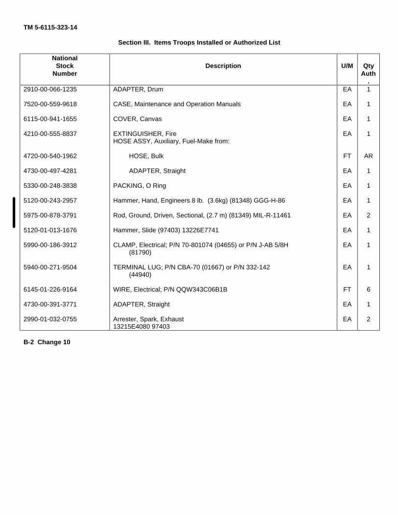
TM 5-6115-323-14
Section III. Items Troops Installed or Authorized List
NationalStock
NumberDescription U/M Qty
Auth.
2910-00-066-1235
7520-00-559-9618
6115-00-941-1655
4210-00-555-8837
4720-00-540-1962
4730-00-497-4281
5330-00-248-3838
5120-00-243-2957
5975-00-878-3791
5120-01-013-1676
5990-00-186-3912
5940-00-271-9504
6145-01-226-9164
4730-00-391-3771
2990-01-032-0755
ADAPTER, Drum
CASE, Maintenance and Operation Manuals
COVER, Canvas
EXTINGUISHER, FireHOSE ASSY, Auxiliary, Fuel-Make from:
HOSE, Bulk
ADAPTER, Straight
PACKING, O Ring
Hammer, Hand, Engineers 8 lb. (3.6kg) (81348) GGG-H-86
Rod, Ground, Driven, Sectional, (2.7 m) (81349) MIL-R-11461
Hammer, Slide (97403) 13226E7741
CLAMP, Electrical; P/N 70-801074 (04655) or P/N J-AB 5/8H(81790)
TERMINAL LUG; P/N CBA-70 (01667) or P/N 332-142(44940)
WIRE, Electrical; P/N QQW343C06B1B
ADAPTER, Straight
Arrester, Spark, Exhaust13215E4080 97403
EA
EA
EA
EA
FT
EA
EA
EA
EA
EA
EA
EA
FT
EA
EA
1
1
1
1
AR
1
1
1
2
1
1
1
6
1
2
B-2 Change 10

TM 5–6115-323-14
APPENDIX C
MAINTENANCE ALLOCATION CHART(Army Only)
Section I. INTRODUCTION
C-1. General
a. This section provides a general explanationof all maintenance and repair functions author-ized at various maintenance levels.
b. Section II designates overall responsibilityfor the performance of maintenance functions onthe identified end item or component and thework measurement time required to perform thefunctions by the designated maintenance level.The implementation of the maintenance functionsupon the end item or component will be consistentwith the assigned maintenance functions.
c. Section III lists the tools and test equipmentrequired for each maintenance function as refer-enced from Section II.
C-2. Explanation of Columns in Section II
a. Column (l), Group Number. Column 1 listsgroup numbers to identify related components,assemblies, subassemblies, and modules with theirnext higher assembly. The applicable groups arelisted in the MAC in disassembly sequence begin-ning with the first group removed.
b. Column (.2), ComponentlAssembly. This col-umn contains the noun names of components,assemblies, subassemblies and modules for whichmaintenance is authorized.
c. Column (3), Maintenance Functions. This col-umn lists the functions to be performed on theitem listed in Column 2. The maintenance func-tions are defined as follows:
(1) Inspect. To determine serviceability of anitem by comparing its physical, mechanical, and/orelectrical characteristics with established stand-ards through examination.
(2) Test. To verify serviceability and detectincipient failure by measuring the mechanical orelectrical characteristics of an item and compar-
ing those characteristics with prescribed stand-ards.
(3) Service. Operations required periodicallyto keep an item in proper operating condition, i.e.,to clean (decontaminate), to preserve, to drain, topaint, or to replenish fuel, lubricants, hydraulicfluids, or compressed air supplies.
(4) Adjust. To maintain within prescribed lim-its, by bringing into proper or exact position, or bysetting the operating characteristics to specifiedparameters.
(5) Align. To adjust specified variable ele-ments of an item to bring about optimum ordesired performance.
(6) Calibrate. To determine and cause correc-tions to be made or to be adjusted on instrumentsor test measuring and diagnostic equipments usedin precision measurement. Consists of comparisonof two instruments, one of which is a certifiedstandard of known accuracy, to detect and adjustany discrepancy in the accuracy of the instrumentbeing compared.
(7) Install. The act of emplacing, seating, orfixing into position an item, part, or module (com-ponent or assembly) in a manner to allow theproper functioning of an equipment or system.
(8) Replace. The act of substituting a service-able like type part, subassembly, or module (com-ponent or assembly) for an unserviceable counter-part.
(9) Repair. The application of maintenanceservices (inspect, test, service, adjust, align, cali-brate, or replace) or other maintenance actions(welding, grinding, riveting, straightening, facing,remachining or resurfacing) to restore serviceabil-ity to an item by correcting specific damage, fault,malfunction, or failure in a part, subassembly,module (component or assembly), end item, orsystem.
(10) Overhaul. That maintenance effort (serv-ice/action) necessary to restore an item to a com-
C-1

TM 5-6115-323-14
pletely serviceable/operational condition as pre-scribed by maintenance standards (i.e., DMWR) inappropriate technical publications. Overhaul isnormally the highest degree of maintenance per-formed by the Army. Overhaul does not normallyreturn an item to a like new condition.
(11) Rebuild. Consists of those services/ac-tions necessary for the restoration of unservicea-ble equipment to a like new condition in accord-ance with original manufacturing standards. Re-build is the highest degree of materiel mainte-nance applied to Army equipment. The rebuildoperation includes the act of returning to zerothose age measurements (hours/miles, etc.) consid-ered in classifying Army equipments/components.
d. Column (4), Maintenance Category. This col-umn is made up of subcolumns for each categoryof maintenance. Work time figures are listed inthese subcolumns for the lowest level of mainte-nance authorized to perform the function listed inColumn 3. These figures indicate the averageactive time required to perform the maintenancefunction at the indicated category of maintenanceunder typical field operating conditions.
e. Column (5), Tools and Equipment. This col-umn is provided for referencing by code, the com-
mon tool sets (not individual tools), special tools,test and support equipment required to performthe designated function.
C-3. Explanation of Columns in Section Ill
a. Column (1), Reference Code. This columnconsists of an arabic number listed in sequencefrom Column 5 of Section II. The number- refer-ences the common tool sets, special tools and testequipment requirements.
b. Column (,2), Maintenance Category. This col-umn shows the lowest category of maintenanceauthorized to use the special tools or test equip- ment.
c. Column (3), Nomenclature. This column lists the name or identification of the common tool sets, special tools or test equipment.
d. Column (4), National/NATO Stock No.(NSN). This column is provided for the NSN ofcommon tool sets, special tools and test equipmentlisted in the nomenclature column.
e. Column (5), Tool Number. This column liststhe manufacturer’s code and part number of toolsand test equipment.
C-2
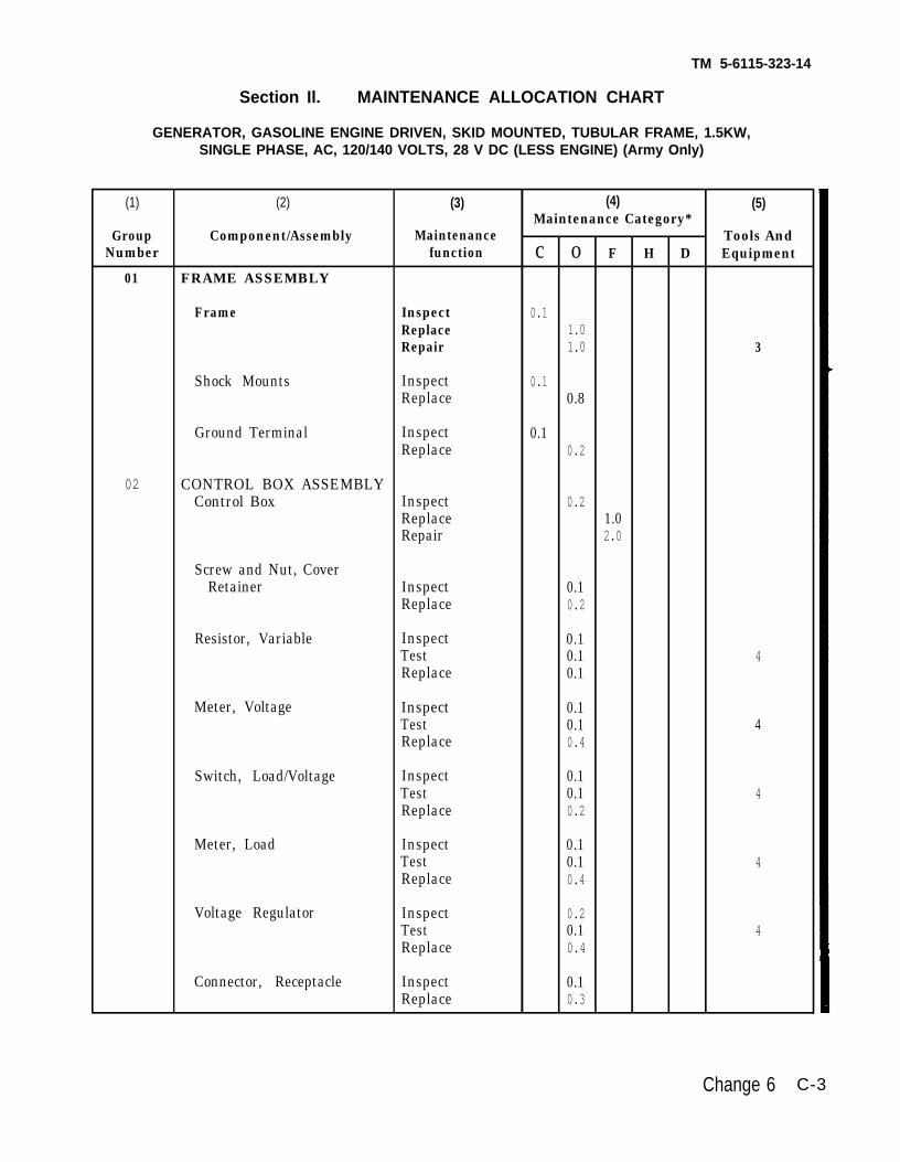
TM 5-6115-323-14
Section Il. MAINTENANCE ALLOCATION CHART
GENERATOR, GASOLINE ENGINE DRIVEN, SKID MOUNTED, TUBULAR FRAME, 1.5KW,SINGLE PHASE, AC, 120/140 VOLTS, 28 V DC (LESS ENGINE) (Army Only)
(1) (2) (3) (4) (5)Maintenance Category*
Group Component/Assembly Maintenance Tools AndNumber function c o F H D Equipment
01 FRAME ASSEMBLY
Frame Inspect 0.1Replace 1.0Repair 1.0 3
Shock Mounts Inspect 0.1Replace 0.8
Ground Terminal Inspect 0.1Replace 0.2
02 CONTROL BOX ASSEMBLYControl Box Inspect 0.2
Replace 1.0Repair 2.0
Screw and Nut, CoverRetainer Inspect 0.1
Replace 0.2
Resistor, Variable Inspect 0.1Test 0.1 4Replace 0.1
Meter, Voltage Inspect 0.1Test 0.1 4Replace 0.4
Switch, Load/Voltage Inspect 0.1Test 0.1 4Replace 0.2
Meter, Load Inspect 0.1Test 0.1 4Replace 0.4
Voltage Regulator Inspect 0.2Test 0.1 4Replace 0.4
Connector, Receptacle Inspect 0.1Replace 0.3
Change 6 C-3

TM 5-6115-323-14
Section Il. MAINTENANCE ALLOCATION CHART (Cont)
GENERATOR, GASOLINE ENGINE DRIVEN, SKID MOUNTED, TUBULAR FRAME, 1.5KW,SINGLE PHASE, AC, 120/140 VOLTS, 28 V DC (LESS ENGINE) (Army Only)
(1) (2) (3) (4) (5)Maintenance Category*
Group Component/Assembly Maintenance Tools AndNumber function c o F H D Equipment
Terminal, Load Block Inspect 0.1Replace 0.3
Wiring Harness Inspect 0.1Test 0.1 4Replace 0.4Repair 1.0
Meter, Frequency Inspect 0.2Test 0.1 4Replace 0.4
Transducer Inspect 0.2Test 0.1 4Replace 0.4
Terminal Load Insulator InspectReplace 0.1
0.3
03 GENERATOR ASSEMBLY
Rotor Assembly Inspect 0.4 2Test 0.1 4Replace 1.0
Bearing Inspect 0.4Replace 1.2
Cooling Fan Inspect 0.2Replace 0.3
Housing Assembly Inspect 0.4Replace 1.5Repair 2.0 3
Stator, Exciter Inspect 0.4Test 0.1 4Replace 2.0Repair 2.0
C-4 Change 6

TM 5-6115-323-14
Section II. MAINTENANCE ALLOCATION CHART (Cent)
GENERATOR, GASOLINE ENGINE DRIVEN, SKID MOUNTED, TUBULAR FRAME, 1.5KW,SINGLE PHASE, AC, 120/140 VOLTS, 28 V DC (LESS ENGINE) (Army Only)
(1) (2) (3) (4) (5)Maintenance Category*
Group Component/Assembly Maintenance Tools And Number function c o F H D Equipment
Housing Replace 2.0Repair 1.0 3
Stator, Alternator Inspect 0.4Test 0.1 4Replace 2.0Repair 2.0
04 FUEL SYSTEM
Tank Inspect 0.1Replace 0.5
Cap and Chain Assembly Inspect 0.1Replace 0.2
Strainer, Fuel Tank Inspect 0.1Replace 0.1
Fuel Filter Inspect 0.1Replace 0.1
Fuel Line Inspect 0.1Replace 0.5
Valve, Three Way Inspect 0.1Replace 0.4
05 ENGINE ASSEMBLY Replace 1.0See TM5-2805-257-14
*SUBCOLUMNS ARE AS FOLLOWS: C-OPERATOR/CREW O-ORGANIZAITONAl F-DIRECT SUPPORT;H-GENERAL SUPPORT; D-DEPOT
**INDICATES WORKTIME/MANHOURS REQUIRED
Change 8 c-5

TM 5-6115-323-14
(1)
Referencecode
1
2
3
4
Section III. TOOL AND TEST EQUIPMEIW REQUIREMENTS
(3
Maintenancecatcgo~
F
F
F
o
(3)I
(4)
Nomenclature I National StockNumber (NSN)
Refer to TM 5-2805-257-14 for Engine Tool and TestEquipment Requirements. Engine Model MIL-STD2A01 6-3.
See Table 5-1, Chapter 5, and Figure 5-1. No other specialtools or tsst equipment, required for listed *emtor sets.
TORCH OUTFIT, CUTTING AND WELDING (Tool Set , 3433-090-357-6311L/l W 67706)
MULTIMETER
*
(5)
Trd Number
ir U.S. GOVERNMENT PRINTING OFFICE 1991 =+123/200S9
C-6 Change 8

TM 5–6115-323-14
ALPHABETICAL INDEXParagraph
A
Administrative Storage ------------------ 1-7Air Cleaner - - - - - - - - - - - - - - - - - - - - - - - - - - - - 3-8Ammeter (DC)
D e s c r i p t i o n - - - - - - - - - - - - - - - - - - - - - - - - - - - 2-11Location _________________________________ F 2-3Removal - - - - - - - - - - - - - - - - - - - - - - - - - - - - - - 4-26b
F 4-18Cleaning & Inspection 4-26cInstal lat ion - - - - - - - - - - - - - - - - - - - - - - - - - - 4-26d
F 4-18
BBreaker, Circuit (DC)
Descr ipt ion - - - - - - - - - - - - - - - - - - - - - - - - - - - -Locat ion - - - - - - - - - - - - - - - - - - - - - - - - - - - - - -Removal - - - - - - - - - - - - - - - - - - - - - - - - - - - - - -
Cleaning & Inspection ---------------------Instal lat ion - - - - - - - - - - - - - - - - - - - - - - - - - -
Test __________________________________
2–1mF 2-3
8-3aF 8-2
8-3b8-3C
F 8-28-3d
cCapacitor (Noise Suppression) (AC)
Removal - - - - - - - - - - - - - - - - - - - - - - - - - - - - - - 8-2aF 8-1
Cleaning & Inspection 8-2bInstallation __________________________ 8-2C
F 8-1Test __________________________________ 8-2d
Capacitor (Noise Suppression) (DC)Removal - - - - - - - - - - - - - - - - - - - - - - - - - - - - - - 8-3a
F 8-2Cleaning & Inspection -------------------------- 8-3bInstal lat ion - - - - - - - - - - - - - - - - - - - - - - - - - - 8-3C
F 8-2Test __________________________________ 8-3d
Carburetor ControlDescr ipt ion - - - - - - - - - - - - - - - - - - - - - - - - - - - - 2–leLocat ion - - - - - - - - - - - - - - - - - - - - - - - - - - - - - - F2-2
Choke LeverDescr ipt ion - - - - - - - - - - - - - - - - - - - - - - - - - - - - 2-1dLocat ion - - - - - - - - - - - - - - - - - - - - - - - - - - - - - - F2-2
Circuit Breaker (DC)Description ____________________________ 2-1mLocation ------------------------------------------------ F 2–3Removal ______________________________ 8-3a
F 8-2Cleaning & Inspection ---------------- 8-3bInstallation __________________________ 8-3C
F 8-2Test __________________________________ 8-3d
Cold, Operation in Extreme -------------- 2-5Components, Control Box (AC) ---------- 4-25
F 4-17Components, Control Box (DC) ---------- 4-26
F 4-18Components, Interference Suppression
Removal (AC) ________________________ F 8-3
Page
1-23-3
2-22-34-244-244–244-244-24
2-22-38-38 48-38-58 48-5
8-18-28-18-18-28-1
8-38 48-38-58-48-5
2-22-2
2-12-2
2-22-38-38-48-38-58-48-52-64-224-234-224-24
8-6
Paragraph
Removal (DC) ________________________ F 8-4T e s t - - - - - - - - - - - - - - - - - - - - - - - - - - - - - - - - - - 8 - 4 dInstallation (AC) ______________________ F 8-3Installation (DC) ______________________ F 8-4
Consumable Operating and MaintenanceSupplies ---------------------------- T 3-1
G e n e r a l - - - - - - - - - - - - - - - - - - - - - - - - - - - - - - 3-1Explanation of Columns -------------- 3-2
Control Box and Bracket (AC)Removal - - - - - - - - - - - - - - - - - - - - - - - - - - - - - - 6-3a
F 6-2Installation __________________________ 6-3b
F 6-2Cleaning & Inspection 8-2bDisassembly - - - - - - - - - - - - - - - - - - - - - - - - - - 8-2a
F 8-1A s s e m b l y - - - - - - - - - - - - - - - - - - - - - - - - - - - - 8-2C
F 8-1Control Box and Bracket (DC)
Removal - - - - - - - - - - - - - - - - - - - - - - - - - - - - - - 6-3aF 6-2
Installation __________________________ 6-3bF 6-2
Cleaning & Inspection ________________ 8-3bDisassembly __________________________ 8-3a
F 8-2Assembly ____________________________ 8-3C
F 8-2Control Box Components (AC) __________ 4-25
F 4-17Control Box Components (DC) __________ 4-26
F 4-18Controls and Instruments -------------- 2-1Conversion, Equipment __________________ 4-3Converter, Frequency
Removal - - - - - - - - - - - - - - - - - - - - - - - - - - - - - - 8-2aF 8-1
Cleaning & Inspection ________________ 8-2bInstallation __________________________ 8-2C
F 8-1Test __________________________________ 8-2d
DData, Identification and Tabulated ------ 1-10Description Generator 1-9Destruction of Army Materiel 1-6Differences Between Models ------------ 1-11Dismantling for Movement ______________ 4-5Dusty or Sandy Areas, Operation in 2-7
EElectrical Connections ------------------ 4-2dEngine
Removal ______________________________ 6-1aF 6-1
Installation __________________________ 6- lbF 6-1
Engine Off-Run SwitchDescription ____________________________ 2-1C
Page
8-78-68-68-7
3-13-13-1
6- l6-26- l6-28-18-18-28-18-2
6- l6-26–16-28-38-38-48-58-44-224-234-224-242-14-3
8-18-28-18-18-28-1
1-51-21-11-84-112-7
4-2
6- l6- l6-16-1
2-1
l-l

TM 5-6115-323-14
Paragraph
Location --------------------------------------------------------F2-2Equipment Conversion ---------------------------------------- 4-3Errors, Reporting of ------------------------------------------ 1-4Exhaust Extension
Removal --------------------------------------------------- 4-16aF 4-8
Cleaning--------------------------------------------- 4-16bInspection-------------------------------------------- 4-16bInstallation---------------------------------------------- 4-16C
F 4-8
FForms and Records, Maintenance 1-3Frame
Removal ______________________________ 7–2aDisassembly -------------------------------------------- 7–2a
F 7-1Cleaning & Inspection ---------------- 7-2bRepair ________________________________ 7-2bAssembly 7–2c
F 7-1Installation __________________________ 7-2c
Frequency ConverterRemoval ______________________________ 8-2a
F 8-1Cleaning & Inspection ------------------------ 8-2bInstallation --------------------------------------------- 8-2C
F 8-1Test __________________________________ 8-2d
Frequency MeterDescription --------------------------------------------- 2-lgLocation ______________________________ F2-3Removal ______________________________ 4-25b
F 4-17Cleaning & Inspection -------------------—————————————— 4-25cInstallation __________________________ 4-25d
F 4-17Test ----------------------------------------------------- 8-2d
Fuel Filter ______________________________ 3-84-21
F4-11Fuel Hose ______________________________ 4-21
F4-11Fuel Selector Valve
Description ____________________________ 2-1bLocation -------------------------------------------------- F2-1Removal ------------------------------------------------- 4-21a
F 4-11Cleaning& Inspection 4-21bInstallation __________________________ 4-21c
F 4-11Fuel Strainer ------------------—-----—— 3-8Fuel Tank
Stainless Steel ________________________ 4-22F 4-12
Nylon ----------------------------------------------------- 4-23F 4-14F 4-15F4-16
Fuel Tank BracketStanless Steel ------------------------------------------- 4-22
F 4-13
Page
2-24-31-1
4-144-144-144-144-144-14
1-1
7-17-17-27-17-17-17-27-1
8-18-28-18-18-2II-1
2-22-34–224-234-224-224-238-13-34-154-164-154-16
2-12-14-154-164-154-154-163-3
4-154-174-174-194-204-21
4-154-18
Nylon
Fuel Tank Cap --------------------------
Paragraph
4-23F 4-15F 4-16
3-9
GGenerator (AC)
Removal . . . . . . . . . . . . . . . . . . . . . . . . . . . . . .
Instal lat ion - - - - - - - - - - - - - - - - - - - - - - - - - -Disassembly . . . . . . . . . . . . . . . . . . . . . . . . . .
Cleaning & InspectionAssembly
T e s t - - - - - - - - - - - - - - - - - - - - - - - - - - - - - - - - - -Generator (DC)
Removal - - - - - - - - - - - - - - - - - - - - - - - - - - - - - -
InstallationDisassembly--------------------------------
Cleaning & InspectionAssembly
T e s t - - - - - - - - - - - - - - - - - - - - - - - - - - - - - - - - - - -Generator Description-------------------------------------Generator (Model MEP-015A)--------------------------
Generator (Model MEP-025A) __________
Ground StrapRemoval ______________________________
Cleaning & InspectionInstallation --------------------------------------------
Ground TerminalRemoval ______________________________
Cleaning & Inspection ________________Installation __________________________
Grounding --------------------------------------------------
HHeating, Operation in Extreme __________Heating Torch
Description ____________________________Operat ion - - - - - - - - - - - - - - - - - - - - - - - - - - - -
High Altitudes, Operation at ____________
IIdentification Data ______________________Inspecting and Servicing the EquipmentInstallation ____________________________Instruments, Controls and --------------Interference Suppression Components
Location ---------------------------------------------
6-4aF6-3F6-4F 6-5
6-4b9-1b
F 9-19-1C9-1d
F 9-19-1f
6-5aF 6-5
6-5b9-2b
F 9-29-2c9-2d
F 9-29-2f1-9
F 1-1
F 1-2F 1-3F 14
4-19aF 4-10
4-19b4–19C
F 4-10
4-18aF 4-9
4-18b4-18c
F 4-94-2c
2-6
2-32-4
F 2-42-10
1-104-14-22-1
4-14
Page
4-174-204-213-4
6-26-36-36-46-29-19-29-19-19-29-1
6-26-46-39-19-49-19-39-49-31-21-3
1 41-51-6
4-154-154-154-154-15
4-144-144-144-154-144-2
2-6
2-42 42-52-7
1-54-14-12-1
4-13
I-2

TM 5-6115-323-14TO 35C2-3-385-1
Removal(AC) ........................................ .Removal(DC) .........................................T e s t . . . . . . . . . . . . . . . . . . . . . . . . . . . . . . . . . . .Installation ..................................... . . . . .Installation (DC) . . . . . . . . . . . . . . . . .
Interference Suppression, Radio ........
L
Levels of Maintenance AccomplishmentLimited Applicability . . . . . . . . . . .Load Meter
Test . . . . . . . . . . . . . . . . . . . .Removal . . . . . . . . . . . . . . . . . . . . . . .
Cleaning & Inspection . . . . . . . . . . .Installation . . . . . . .
Load SwitchDescription . . . . . . . . . . . . . . . . . . .Location . . . . . . . . . . . . . . . . . . .Test . . . . . . . . . . . .Removal . . . . . . . . . . . . . . . . . . . . . .Cleaning & Inspection . . . . . . . . . . .Installation . . . . . . . . . . . . . . .
M
Maintenance Accomplishment,Levels of . . . . . . . . . . . . . . . . . . . .
Maintenance Forms and Records ..........Maintenance, Preventive .........................
M a i n t e n a n c e R e p a i r P a r t sMeter, Frequency
Description . . . . . . . . . . . . . . . . .Location . . . . . .Removal . . . . . . . . . . . . . . . . . . . . .
Cleaning & Inspection . . . .... . . . . . . .Installation........... . . . . . . . . . . . . . . . . . . .
Test . . . . . . . . . . . . . . . . . . .Meter, Load
Test . . . . .Removal . . . . . . . . . . . . .
C l e a n i n g & I n s p e c t i o nInstallation . . . . . . .
M o d e l s , D i f f e r e n c e s B e t w e e nModel MEP-015A . . . . . . . . . . . . . . . . .
Model MEP-015A, Schematic DiagramModel MEP-015A, Wiring DiagramModel MEP-025A . . . . . . . . . . . . . . . . . . . . . . . . .
Model MEP-025A, Schematic DiagramModel MEP-025A, Wiring DiagramMovement, Dismantling for ...........
Paragraph
F8-3F8-4
8-4dF8-3F8-4
8-4
1-51-2
4-26a4-26b
F4-184-26c4-26d
F4-18
2-lhF2-3
4-25a4-25b4-25c4-25d
F4-17
1-51-33-4
T3-24-10
T4-14-8
2-lgF2-3
4-25bF4-17
4-25c4-25d
F4-178-2d
4-26a4-26b
F4-184-26c4-26d
F4-181-11
F1-1F1-2F1-7F1-5F1-3F1-4F1-8F1-6
4-5
Page
8-68-78-68-68-78-6
1-11-1
4-224-244-244-244-244-24
2-22-34-224-224-224-224-23
1-11-13-23-24-114-124-11
2-22-34-224-234-224-224-238-1
4-224-244-244-244-244-241-81-31-41-111-91-51-61-121-104-11
O
Operation at High Altitudes ........................Operation in Dusty or Sandy Areas ............Operat ion in Extreme Cold . . . . . . .Operat ion in Extreme Heat . . . . . .Operation in Salt Water Areas .. . .Operation Under Rainy or Humid
Conditions . . . . . . . . . . . . . . . . . . . . .Operation Under Usual Conditions . . . . . . .
P
Preparation for Shipment and StorageP r e v e n t i v e M a i n t e n a n c e . . . .
R
Radio Interference Suppression ........Rainy or Humid Conditions, Operation
Under . . . . . . . . . . . . .Reinstallation .....................................Repair Parts, Maintenance ..........................R e p o r t i n g o f E r r o r s . . . . . .Resistor, Variable (AC)
Description . . . . . . . . . . . . . . . .Location...............................................Removal ...........................
Cleaning & Inspection .........................................Installation . . . . . . . . . . . . . . . .
Test . . . . . . . . . . . . . . . . . . . . . . . . . . . . . . . . . . . . . . .Resistor, Variable (DC)
Description . . . . . . . . .L o c a t i o n . . . . . . . . . . . . . . . . . .R e m o v a l . . . . . . . . . . . . . . . . . . . . . . .
Cleaning & Inspection ................................I n s t a l l a t i o n . . . . . . . . . . . . . . . . . . . . . . . .
T e s t . . . . . . . . . . . . . . . . . . . . . . . . .R e v e t m e n t . . . . . . . . . . . . . . . . . . . . . .
s
Salt Water Areas, Operation in ..................Schematic Diagram (Model ME P-O 15A) ............Schematic Diagram (Model ME P-025A) ..............S c o p e . . . . . . . . . . . . . . . . . . . . . . . . . . .Servicing and Inspecting the Equipment .....Shipment and Storage, Preparation for ........Shunt
R e m o v a l . . . . . . . . . . . . . . . . . . . . .
Paragraph
2-102-72-52-62-9
2-82-2
1-83-3
T3-24-10
T4-1
8-4
2-84-64-81-4
2-1iF2-3
4-25bF4-17
4-25c4-25d
F4-178-2d
2-1nF2-3
4-26aF4-18
4-26c4-26d
F4-188-3d4-4
2-9F1-7F1-8
1-14-11-8
4-26b
Page
2-72-72-62-62-7
2-72-4
1-23-23-24-114-12
8-6
2-74-114-111-1
2 22-34-224-234-224-224-238-1
2-22-34-224-244-244-244-248-14-3
2-71-111-121-14-11-2
4-24
Cleaning & Inspection ....................Installation .....................................
S t a r t i n g . . . . . . . . . . . . . . . . . . . . . . . .Stopping . . . . . . .Storage, Administrative ................................. Strap, Ground
R e m o v a l . . . . . . . . . . . . . . . . . . . . . . . .
F4-184-26c4-26d
F4-182-2b2-2d1-7
4-19aF4-10
Change 5
4-244-244-244-242-12-11-2
4-154-15
I-3

TM 5-6115-323-14
Paragraph
Cleaning & Inspection .................... 4-19bInstallation . . . . . . . . . . . . . . . . . . 4-19C
F4-10Supplies, Consumable Operating and
Maintenance . . . . . . . . . . . . . . . . T3-1General . . . . . . . . . . . . . . . . . . . . . . . . . 3-1Explanation of Columns ........... 3-2
Suppression . . . . . . . . . . . . . . . . . . . 4-13Suppression Components, Interference 4-14Switch, Engine Off-Run
Description . . . . . . . . . . . . . . . . . . . 2-lCLocation . . . . . . . . . . . . . . . . . . . . . F2-2
Switch, LoadDescription . . . . . . . . . . . . . . . . . . . 2-lhLocation . . . . . . . . . . . . . . . . . . . . F2-3Test . . . . . . . . . . . . . . . . . . . . . . . . . 4-25aRemoval . . . . . . . . . . . . . . . . . . . . . . . 4-25b
F4-17Cleaning & Inspection . . . . . . . . . . . . 4-25cInstallation . . . . . . . . . . . . . . . . . . 4-25d
F4-17Switch, Voltage Change
Description, . . . . . . . . . . . . . . . . . . 2-1jLocation . . . . . . . . . . . . . . . . . . . . F2-3Test . . . . . . . . . . . . . . . . . . . . . . . . . . . 4-25aRemoval . . . . . . . . . . . . . . . . . . . . . . . . 4-25b
F4-17Cleaning & Inspection .......................... 4-25cInstallation . . . . . . . . . . . . . . . . . . . 4-25d
F4-17
T
Tabulated Data . . . . . . . . . . . . . . . . . 1-10Terminal, Ground
Removal . . . . . . . . . . . . . . . . . . . . . . . 4-18a
Cleaning & Inspection ........................Installation . . . . . . . . . . . . . . . . . .
F4-94-18b4-18c
F4-9T o o l s a n d E q u i p m e n t . . . . . . . . 4-7
5-1T5-1
Torch, HeatingDescription . . . . . . . . . . . . . . . . . . . 2-3Operation . . . . . . . . . . . . . . . . . . . . 2-4
F2-4Transducer
Removal . . . . . . . . . . . . . . . . . . . . . . . . 8-2aF8-1
Cleaning & Inspection . . . . . . . . . . . . 8-2bInstallation . . . . . . . . . . . . . . . . . . . 8-2c
F8-1Test . . . . . . . . . . . . . . . . . . . . . . . . . . . 8-2d
Troubleshooting . . . 3-5T3-3
4-12T4-2
5-4T5-2
Page
4-154-154-15
3-13-13-14-134-13
2-12-2
2-22-34-224-224-234-224-224-23
2-22-34-224-224-234-224-224-23
1-5
4-144-144-144-154-144-115-15-1
2-42-42-5
8-18-28-18-18-28-13-2.13-34-124-125-35-3
V
Valve, Fuel SelectionDescription . . . . . . . . . . . . . . . . . . .L o c a t i o n . . . . . . . . . . . . . . . . . .R e m o v a l . . . . . . . . . . . . . . . . . . . . . .
Cleaning & Inspection . . . . . . . . . . . .Installation . . . . . . . . . . . . . . . . . .
Variable Resistor (AC)Description . . . . . . . . . . . . . . . . . . . .L o c a t i o n . . . . . . . . . . . . . . . . . .R e m o v a l . . . . . . . . . . . . . . . . . . . . .
Cleaning & Inspection . . . . . . . . . .I n s t a l l a t i o n . . . . . . . . . . . . . . . . . . .
Test . . . . . . . . . . . . . . . . . . . . . . . . .Variable Resistor (DC)
Description . . . . . . . . . . . . . . . . . .L o c a t i o n . . . . . . . . . . . . . . . . . . . . .R e m o v a l . . . . . . . . . . . . . . . . . . . . . . . . .
Cleaning & Inspection . . . . . . . . . .Installation . . . . . . . . . . . . . . . . . .
Test . . . . . . . . . . . . . . . . . . . . . . . . .Voltage Change Switch
Description . . . . . . . . . . . . . . . . . . .Location .....................................................Test . . . . . . . . . . . . . . . . . . . . . . . . . .Removal ..........................................
Cleaning & Inspection . . . . . . . . . . .Installation . . . . . . . . . . . . . . . . . . .
Voltage Regulator (AC)Removal & Disassembly
Cleaning & Inspection . . . . . . . . . .Assembly & Installation .............................
Test . . . . . . . . . . . . . . . . . . . . . . . . . .Voltage Regulator (DC)
Removal & Disassembly . . . . . . . . . . .
Cleaning & Inspection . . . . . . . . . . .Assembly & Installation ..........................
Test . . . . . . . . . . . . . . . . . . . . . . . . . .Voltmeter (AC)
Description . . . . . . . . . . . . . . . . . . .L o c a t i o n . . . . . . . . . . . . . . . . . . . . .Test . . . . . . . . . . . . . . . . . . . . . . . . . .R e m o v a l . . . . . . . . . . . . . . . . . . . . . . .
Cleaning & Inspection . . . . . . . . . . .Installation . . . . . . . . . . . . . . . . . . .
Voltmeter (DC)
Paragraph
2-lbF2-1
4-21aF4-11
4-21b4-2c
F4-11
2-1iF2-3
4-25bF4-17
4-25c4-25d
F4-178-2d
2-1nF2-3
4-26bF4-18
4-26c4-26d
F4-188-3d
2-ljF2-3
4-25a4-25b
F4-174-25c4-25d
F4-17
8-2aF8-1
8-2b8-2c
F8-18-2d
8-3aF8-2
8-3b8-3c
F8-28-3d
2-1fF2-3
4-25a4-25b
F4-174-25c4-25d
F4-17
D e s c r i p t i o n . . . . . . . . . . . . . . . . 2-lkL o c a t i o n . . . . . . . . . . . . . . . . . F2-3
Page
2-12-14-154-164-154-154-16
2-22-34-224-234-224-224-238-1
2-22-3 4-24 4-244-244-244-248-5
2-22-34-224-224-234-22 4-224-23
8-18-28-18-18-28-1
8-38-48-38-58-48-5
2-22-34-224-224-234-224-224-23
2-22-3
I-4 Change 5 PIN: 015378 005

Paragraph
Test . . . . . . . . . . . . . . . . . . . . . . . . . . . . . . . . . . 4-26aRemoval - - - - - - - - - - - - - - - - - - - - - - - - - - - - - - 4-26b
F 4-18Cleaning & Inspection 426cInstal lat ion - - - - - - - - - - - - - - - - - - - - - - - - - - 4-26d
wWiring Diagram (Model MEP-015A)
F 4-18
F 1-5
Page
4-224-244-244-244-244-24
1-9
TM 5-6115-323-14
Paragraph Page
Wiring Diagram (Model MEP-025A) ---- F 1-6 1-10Wiring Harness
Inspection ____________________________ 8-5a 8-7T e s t - - - - - - - - - - - - - - - - - - - - - - - - - - - - - - - - - - 8-5b 8-7Repair - - - - - - - - - - - - - - - - - - - - - - - - - - - - - - - - 8-5c 8-7Removal ______________________________ 8-5d 8-7Instal lat ion - - - - - - - - - - - - - - - - - - - - - - - - - - 8-5e 8-7
I-5


TM 5-6115-323-14
By Order of the Secretary of the Army:FRED C. WEYANDGeneral, United Staten Army
Official: Chief of StaffPAUL T. SMITHMajor General, United States ArmyThe Adjutant General
DISTRIBUTION:To be distributed in accordance with DA Form 12-25D, organizational maintenance requirements for
Generator Set, 1.5 KW 60 HZ.


Related Documents