APPLICATION NOTE Atmel AVR928: Scalar Sensorless Methods to Drive BLDC Motors Atmel AVR 8-bit Microcontrollers Features • Robust sensorless commutation control • Ramp-up sequence Description This application note describes how to implement a sensorless commutation on BLDC motors. Starting with a simple model of the BLDC motor, the basis of sensorless commutation will be explained. Technical constraints and requirements for the implementation will be described. The goal of this application note is to provide all information that is relevant for an implementation of sensorless commutation using the Atmel devices and Starter-kits. 8305B−AVR−07/2013

Welcome message from author
This document is posted to help you gain knowledge. Please leave a comment to let me know what you think about it! Share it to your friends and learn new things together.
Transcript
APPLICATION NOTE
Atmel AVR928: Scalar Sensorless Methods to Drive BLDC Motors
Atmel AVR 8-bit Microcontrollers
Features
• Robust sensorless commutation control
• Ramp-up sequence
Description
This application note describes how to implement a sensorless commutation on BLDC motors.
Starting with a simple model of the BLDC motor, the basis of sensorless commutation will be explained.
Technical constraints and requirements for the implementation will be described.
The goal of this application note is to provide all information that is relevant for an implementation of sensorless commutation using the Atmel devices and Starter-kits.
8305B−AVR−07/2013
Atmel AVR928: Scalar Sensorless Methods to Drive BLDC Motors [APPLICATION NOTE] 8305B−AVR−07/2013
2
Table of Contents
1. Glossary ............................................................................................. 3
2. BLDC Motor Theory ........................................................................... 3 2.1 Simplified Model of a BLDC Motor .................................................................... 3 2.2 Six-step commutation ........................................................................................ 4 2.3 Power Stage...................................................................................................... 5
3. BEMF…………… ............................................................................... 5 3.1 BEMF zero-crossing .......................................................................................... 6 3.2 BEMF vs. Hall Sensors ..................................................................................... 6 3.3 BEMF constant.................................................................................................. 7
4. Sensorless control method ................................................................. 7 4.1 PWM Schemes ................................................................................................. 7
4.1.1 Low-Side PWM Scheme ..................................................................... 8 4.1.2 Symmetrical PWM Scheme ................................................................ 8
4.2 BEMF signals characteristics ............................................................................ 8 4.2.1 Slope…… ........................................................................................... 8 4.2.2 Noise….. ............................................................................................. 8 4.2.3 Equations ............................................................................................ 9
4.3 Zero-crossing detection ................................................................................... 11 4.3.1 Signal conditioning ............................................................................ 11 4.3.2 30° phase angle ................................................................................ 11
5. Sensorless method flowchart ........................................................... 13 5.1 Alignment phase : ALIGN ................................................................................ 14 5.2 Open Loop Acceleration Up phase : RAMP_UP ............................................. 14
5.2.1 Step time variable ............................................................................. 14 5.2.2 Duty cycle variable ............................................................................ 14 5.2.3 BEMF detection ................................................................................ 15 5.2.4 Torque…. .......................................................................................... 15 5.2.5 S-shape.. .......................................................................................... 15 5.2.6 Interactive adjustment of ramp-up table parameters ......................... 16 5.2.7 Current Limit parameter .................................................................... 17
5.3 Regulation phase : RUNNING........................................................................ 18 5.3.1 Thirty degree phase angle and Demagnetization ............................. 18
6. Tuning…. ......................................................................................... 19
7. Summary ......................................................................................... 20
8. Revision History ............................................................................... 21
Atmel AVR928: Scalar Sensorless Methods to Drive BLDC Motors [APPLICATION NOTE] 8305B−AVR−07/2013
3
1. Glossary • BLDC: Brushless DC
• BEMF: Back Electro Motive Force
• PWM: Pulse Width Modulation
• PSC: Power Stage Controller
• IGBT: Insulated Gate Bipolar Transistor
2. BLDC Motor Theory Brushless DC motors (BLDC) are more reliable than standard DC (mechanically commutated) motors. BLDC motors are more suitable for control and regulation.
BLDC motors are synchronous motors. The switching control must be synchronized to rotor position. It can be achieved in two different ways:
- Sensored mode which uses the Hall sensors
- or Sensorless mode (do not use Hall sensors)
The sensored control drawbacks are: - cost of Hall effect sensors, wirings and connector
- potential failure of the sensors
For these reasons, sensorless control reduces the motor and system costs.
Due to physical constraints (BEMF and PWM noise voltage levels), sensorless commutation requires a minimum speed to work.
Sensorless commutation is suitable for those applications where a motor turns at speed beyond this limit like fans or pumps where the mechanical load does not change abruptly. Fans and rotary pumps are predictable and fairly well behaved.
Operating a BLDC motor in sensorless beyond its typical speed limit makes it similar to a BLDC motor equipped with Hall sensors. So, in the following chapters, we will consider virtual Hall sensors (Hall states 30° and Hall Sensor like signals) to clarify the explanations regarding rotor position and switching times.
2.1 Simplified Model of a BLDC Motor A simplified model of a BLDC motor consists of three coils arranged in three directions U, V and W (Figure 2-1). A permanent magnet forms the rotor. Here the rotor is outlined as a bar magnet with its rotary axis at the intersection of the three axes U, V, W perpendicular to the plane of these axis. The orientation/position of the permanent magnet can be controlled by driving a configuration of currents through the three coils. The bar magnet comes to position sector 1 when a current is driven from W through V and it comes to the following orientation (sector 2) when a current is driven from W to U.
For a BLDC motor that is equipped with Hall sensors, these sensors give the actual rotor position.

Atmel AVR928: Scalar Sensorless Methods to Drive BLDC Motors [APPLICATION NOTE] 8305B−AVR−07/2013
4
Figure 2-1. Simplified Model of a BLDC Motor
2.2 Six-step commutation The method for energizing the motor windings in the sensorless method described in this application note is the six-step commutation. Each step, or sector, is equivalent to 60 electrical degrees. Six sectors make up 360 degrees, or one electrical revolution.
The arrows in the winding diagram (Figure 2-2) show the direction current flows through the motor windings in each of the six sectors.
The graph (Figure 2-3) shows the voltage applied at each lead of the motor during the six sectors. Sequencing through these six sectors moves the motor one electrical revolution.
For every sector, two windings are energized and one is not energized. The fact that one of the windings is not energized during each sector is an important characteristic for the use of the scalar sensorless control theory.
Figure 2-2. Model of a BLDC Motor with current flows versus rotor positions

Atmel AVR928: Scalar Sensorless Methods to Drive BLDC Motors [APPLICATION NOTE] 8305B−AVR−07/2013
5
Figure 2-3. Commutation sequence
Notes:
- Open phase is the one shown with dotted line
- Hall states are detailed in 3.2 section
2.3 Power Stage The commutation pattern is controlled with a 3-phase bridge (see Figure 2-4). This bridge has 6 power switches (IGBT or MOSFET transistors) which are switched according to the defined commutation pattern.
Figure 2-4. 3-phases bridge
3. BEMF The motion of the rotor induces alternating voltages called Back ElectroMotive Force (BEMF) within the coils. This voltage is generated in the stator winding by the permanent magnet rotor when it is turning, acting as a generator.
The BEMF can be modeled as a voltage source in series with each coil.
The BEMF voltage characteristics are:
Atmel AVR928: Scalar Sensorless Methods to Drive BLDC Motors [APPLICATION NOTE] 8305B−AVR−07/2013
6
- assumed as a sine wave but approximately trapezoidal shape
- amplitude is proportional to the rotor speed
- slope varies also versus rotor speed
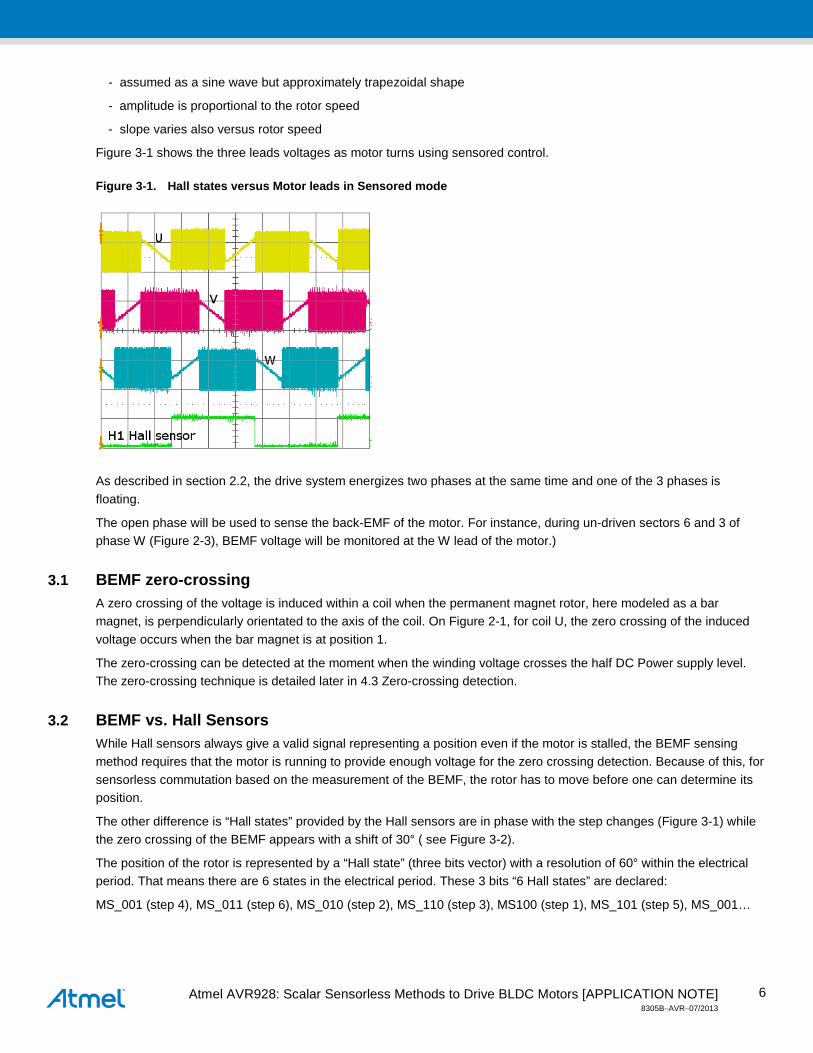
Figure 3-1 shows the three leads voltages as motor turns using sensored control.
Figure 3-1. Hall states versus Motor leads in Sensored mode
As described in section 2.2, the drive system energizes two phases at the same time and one of the 3 phases is floating.
The open phase will be used to sense the back-EMF of the motor. For instance, during un-driven sectors 6 and 3 of phase W (Figure 2-3), BEMF voltage will be monitored at the W lead of the motor.)
3.1 BEMF zero-crossing A zero crossing of the voltage is induced within a coil when the permanent magnet rotor, here modeled as a bar magnet, is perpendicularly orientated to the axis of the coil. On Figure 2-1, for coil U, the zero crossing of the induced voltage occurs when the bar magnet is at position 1.
The zero-crossing can be detected at the moment when the winding voltage crosses the half DC Power supply level. The zero-crossing technique is detailed later in 4.3 Zero-crossing detection.
3.2 BEMF vs. Hall Sensors While Hall sensors always give a valid signal representing a position even if the motor is stalled, the BEMF sensing method requires that the motor is running to provide enough voltage for the zero crossing detection. Because of this, for sensorless commutation based on the measurement of the BEMF, the rotor has to move before one can determine its position.
The other difference is “Hall states” provided by the Hall sensors are in phase with the step changes (Figure 3-1) while the zero crossing of the BEMF appears with a shift of 30° ( see Figure 3-2).
The position of the rotor is represented by a “Hall state” (three bits vector) with a resolution of 60° within the electrical period. That means there are 6 states in the electrical period. These 3 bits “6 Hall states” are declared:
MS_001 (step 4), MS_011 (step 6), MS_010 (step 2), MS_110 (step 3), MS100 (step 1), MS_101 (step 5), MS_001…

Atmel AVR928: Scalar Sensorless Methods to Drive BLDC Motors [APPLICATION NOTE] 8305B−AVR−07/2013
7
Figure 3-2. BEMF versus Hall states
For next explanations, virtual Hall sensors are considered in such a way that the zero crossing of the BEMF occurs as close as possible to the toggle of the virtual Hall sensor signal associated with the corresponding coil. For this purpose, from the zero-crossing detection, a 30° shift is calculated to provide the virtual Hall sensors signals. This calculation is described in details in 4.3.2 (30° phase angle).
In section 4.2.3 (Equations) page 9, H1 is associated with U, H2 is associated with V, and H3 is associated with W.
3.3 BEMF constant As described above, BEMF is proportional to speed (Sp) and the BEMF constant (k_e) is specified, for a motor, in V/rpm unit.
BEMF = k_e[V/rpm] * Sp[rpm]
At a given supply voltage, the BEMF limits the speed of a motor.
4. Sensorless control method The key of the sensorless control method is to determine the appropriate moment when the motor winding should be commutated. This moment is determined by the rotor position. With sensored control, the rotor position is well known. However, in sensorless control, rotor position must be determined by another mean.
The sensorless scheme described in this Application note uses the accurate detection of the BEMF zero-crossing.
4.1 PWM Schemes Pulse-width modulation is used to apply a variable voltage to the motor windings. Changing the PWM duty-cycle of the transistors (T1 to T6) signals, changes the amount of current flowing through the windings of the motor.
Two most common drive schemes are used for block commutation:
- Low-Side PWM scheme
- Symmetric PWM scheme
Atmel AVR928: Scalar Sensorless Methods to Drive BLDC Motors [APPLICATION NOTE] 8305B−AVR−07/2013
8
The effective voltage is proportional to the PWM duty cycle. This voltage will determine the speed and the available torque of the motor.
The PWM frequency must be much higher than the motor frequency. A usual rule is to configure the PWM at least 10 times the maximum motor frequency.
Another advantage to use PWM is that DC power-supply voltage can be much higher than the motor rated voltage. This provides flexibility to match the controller to different motors and voltages.
4.1.1 Low-Side PWM Scheme In this scheme, PWM signal is only applied to Bottom transistors of the three-phase bridge. One phase is driven high, one is being pulse-width modulated and the third phase is open. This method provides a low cost solution.
With this commutation scheme, the N neutral connection of the motor is not a constant dc voltage and working with this method is problematic for sensorless control.
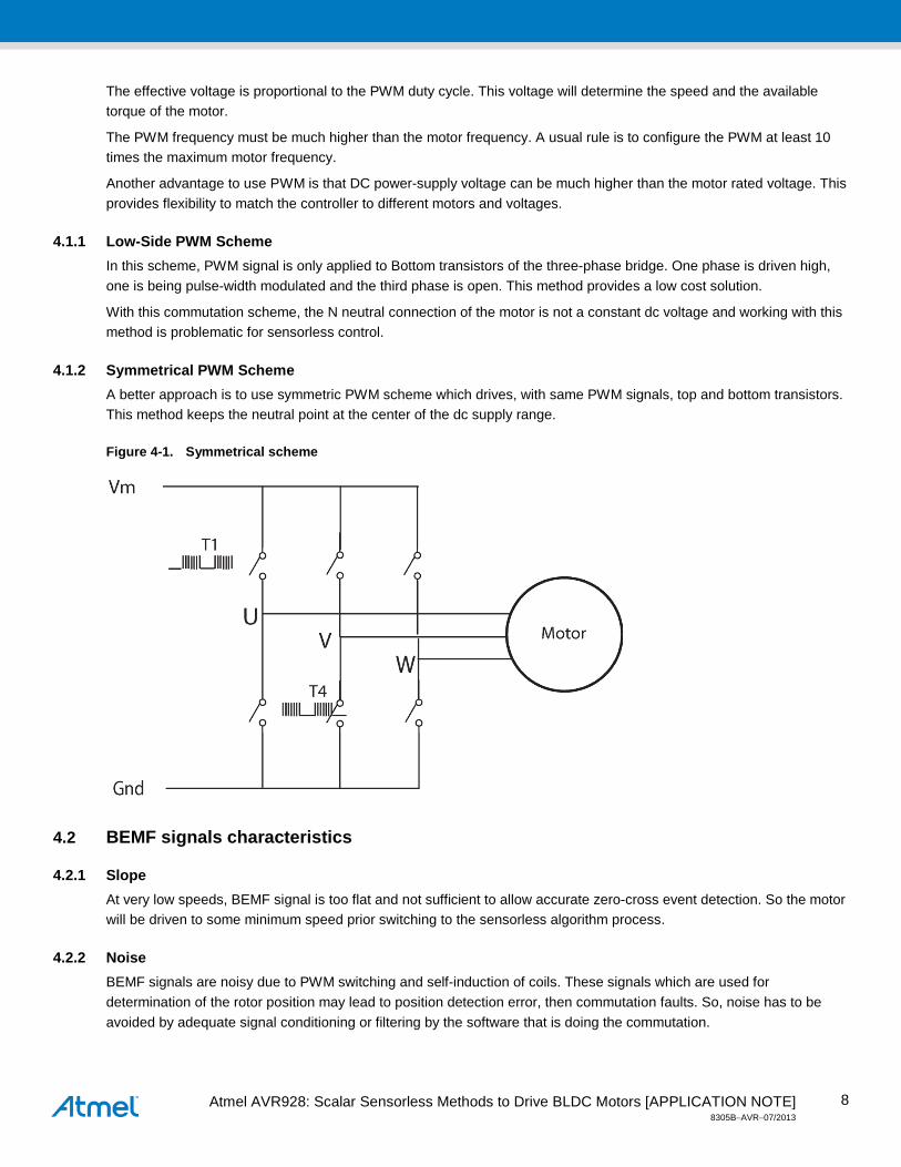
4.1.2 Symmetrical PWM Scheme A better approach is to use symmetric PWM scheme which drives, with same PWM signals, top and bottom transistors. This method keeps the neutral point at the center of the dc supply range.
Figure 4-1. Symmetrical scheme
4.2 BEMF signals characteristics
4.2.1 Slope At very low speeds, BEMF signal is too flat and not sufficient to allow accurate zero-cross event detection. So the motor will be driven to some minimum speed prior switching to the sensorless algorithm process.
4.2.2 Noise BEMF signals are noisy due to PWM switching and self-induction of coils. These signals which are used for determination of the rotor position may lead to position detection error, then commutation faults. So, noise has to be avoided by adequate signal conditioning or filtering by the software that is doing the commutation.
Atmel AVR928: Scalar Sensorless Methods to Drive BLDC Motors [APPLICATION NOTE] 8305B−AVR−07/2013
9
Digital filtering is a powerful method but it consumes processing power. This software filtering is not required if the signals are well conditioned without noise.
4.2.3 Equations
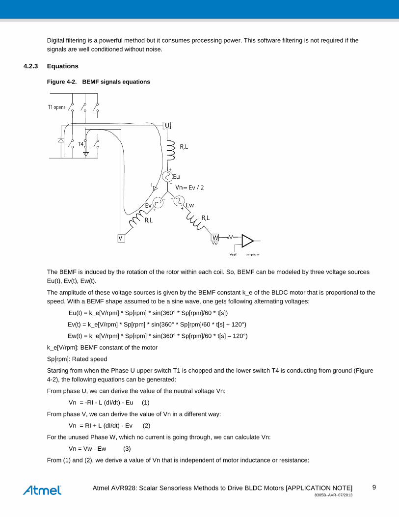
Figure 4-2. BEMF signals equations
The BEMF is induced by the rotation of the rotor within each coil. So, BEMF can be modeled by three voltage sources Eu(t), Ev(t), Ew(t).
The amplitude of these voltage sources is given by the BEMF constant k_e of the BLDC motor that is proportional to the speed. With a BEMF shape assumed to be a sine wave, one gets following alternating voltages:
Eu(t) = k_e[V/rpm] * Sp[rpm] * sin(360° * Sp[rpm]/60 * t[s])
Ev(t) = k_e[V/rpm] * Sp[rpm] * sin(360° * Sp[rpm]/60 * t[s] + 120°)
Ew(t) = k_e[V/rpm] * Sp[rpm] * sin(360° * Sp[rpm]/60 * t[s] – 120°)
k_e[V/rpm]: BEMF constant of the motor
Sp[rpm]: Rated speed
Starting from when the Phase U upper switch T1 is chopped and the lower switch T4 is conducting from ground (Figure 4-2), the following equations can be generated:
From phase U, we can derive the value of the neutral voltage Vn:
Vn = -RI - L (dI/dt) - Eu (1)
From phase V, we can derive the value of Vn in a different way:
Vn = RI + L (dI/dt) - Ev (2)
For the unused Phase W, which no current is going through, we can calculate Vn:
Vn = Vw - Ew (3)
From (1) and (2), we derive a value of Vn that is independent of motor inductance or resistance:
Atmel AVR928: Scalar Sensorless Methods to Drive BLDC Motors [APPLICATION NOTE] 8305B−AVR−07/2013
10
2 * Vn = -Eu -Ev
Vn = (-Eu -Ev) / 2 (4)
In a balanced three-phase system the sum of the phase EMF voltages is equal to zero:
Eu + Ev + Ew = 0 (5)
Incorporating equation (5) into equation (4) yields:
Vn = Ew / 2 (6)
Using equations (3) and (6) the terminal voltage Vw can be expressed:
Vw = 3/2 Ew (7)
We observe:
- the voltage seen at Vw is zero when the Ew BEMF on phase W is crossing zero.
- the gain of the BEMF signal is 150% of the actual BEMF.
This confirms the sensitivity of this BEMF sensing method.
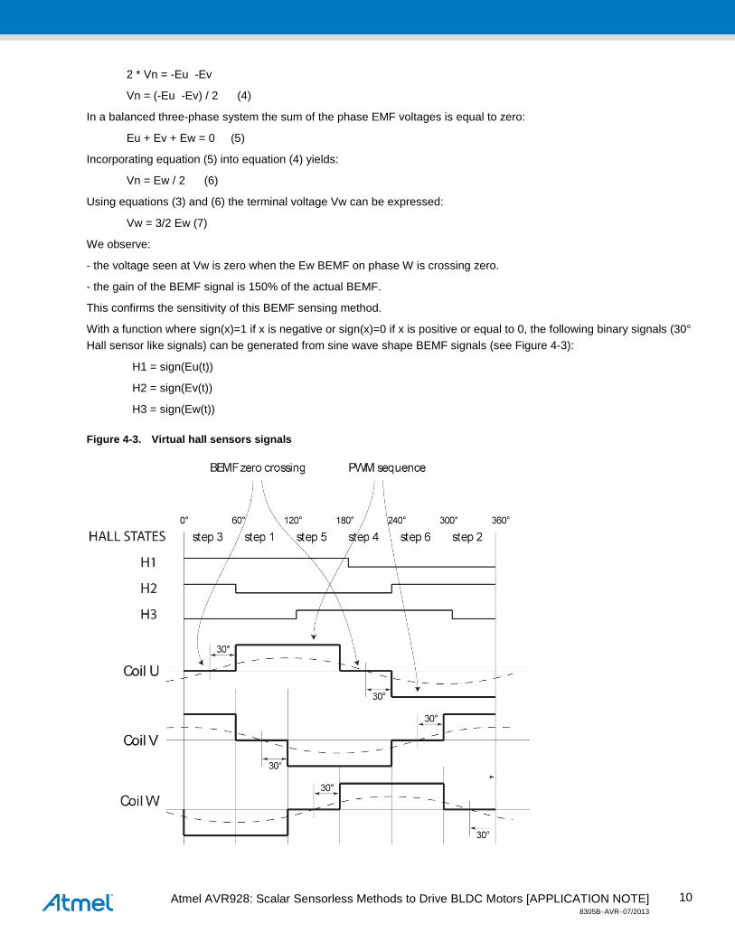
With a function where sign(x)=1 if x is negative or sign(x)=0 if x is positive or equal to 0, the following binary signals (30° Hall sensor like signals) can be generated from sine wave shape BEMF signals (see Figure 4-3):
H1 = sign(Eu(t))
H2 = sign(Ev(t))
H3 = sign(Ew(t))
Figure 4-3. Virtual hall sensors signals
Atmel AVR928: Scalar Sensorless Methods to Drive BLDC Motors [APPLICATION NOTE] 8305B−AVR−07/2013
11
4.3 Zero-crossing detection The BEMF zero-crossing signal is used to provide a position feedback to estimate the right commutation instant.
4.3.1 Signal conditioning Atmel microcontrollers offer Analog Comparator feature which will be used to process the electrical signals.
Three internal comparators are used to detect the zero crossing of the BEMF of U, V and W phases.
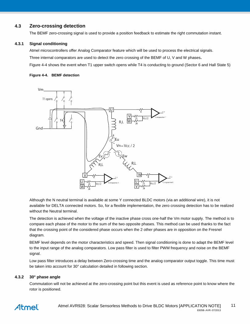
Figure 4-4 shows the event when T1 upper switch opens while T4 is conducting to ground (Sector 6 and Hall State 5)
Figure 4-4. BEMF detection
Although the N neutral terminal is available at some Y connected BLDC motors (via an additional wire), it is not available for DELTA connected motors. So, for a flexible implementation, the zero crossing detection has to be realized without the Neutral terminal.
The detection is achieved when the voltage of the inactive phase cross one-half the Vm motor supply. The method is to compare each phase of the motor to the sum of the two opposite phases. This method can be used thanks to the fact that the crossing point of the considered phase occurs when the 2 other phases are in opposition on the Fresnel diagram.
BEMF level depends on the motor characteristics and speed. Then signal conditioning is done to adapt the BEMF level to the input range of the analog comparators. Low pass filter is used to filter PWM frequency and noise on the BEMF signal.
Low pass filter introduces a delay between Zero-crossing time and the analog comparator output toggle. This time must be taken into account for 30° calculation detailed in following section.
4.3.2 30° phase angle Commutation will not be achieved at the zero-crossing point but this event is used as reference point to know where the rotor is positioned.
Atmel AVR928: Scalar Sensorless Methods to Drive BLDC Motors [APPLICATION NOTE] 8305B−AVR−07/2013
12
The useful electrical (and mechanical) power is:
Pe = E * I
So to get the best efficiency of the control system, the signals:
- Current in the motor phases
- Back EMF voltages
must be kept in phase.
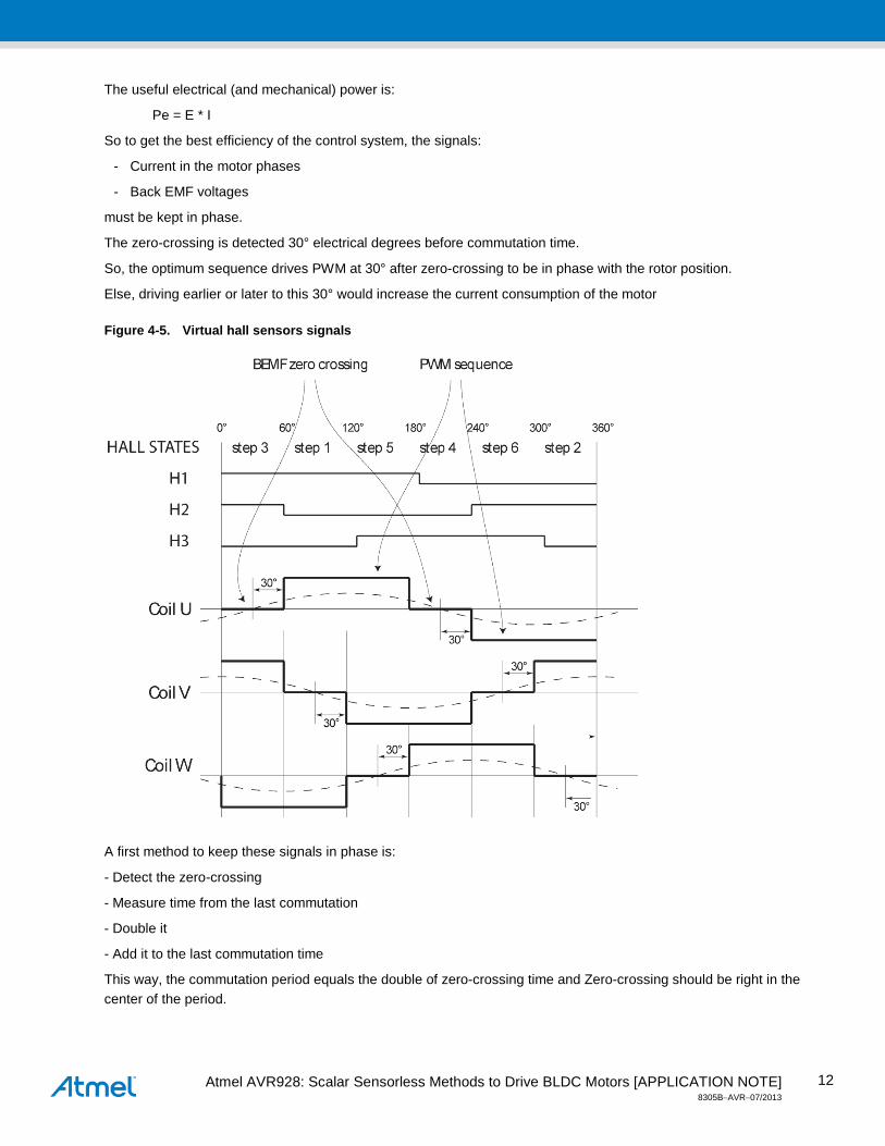
The zero-crossing is detected 30° electrical degrees before commutation time.
So, the optimum sequence drives PWM at 30° after zero-crossing to be in phase with the rotor position.
Else, driving earlier or later to this 30° would increase the current consumption of the motor
Figure 4-5. Virtual hall sensors signals
A first method to keep these signals in phase is:
- Detect the zero-crossing
- Measure time from the last commutation
- Double it
- Add it to the last commutation time
This way, the commutation period equals the double of zero-crossing time and Zero-crossing should be right in the center of the period.

Atmel AVR928: Scalar Sensorless Methods to Drive BLDC Motors [APPLICATION NOTE] 8305B−AVR−07/2013
13
But due to PWM noise, dynamical changes, the zero-crossing event could occur at a different time and be lost. A more robust method can be used to predict the zero-crossing detection in a time window. This window will validate the zero-crossing detection. If detection occurs inside this window, the commutation will be re-calculated else commutation will be achieved with the last predicted time.
As speed increases, the zero crossing event will happen earlier and the computed delay must be decreased to keep the 2 signals in phase.
5. Sensorless method flowchart The sensorless control method can be easily developed with Atmel microcontrollers thanks to the embedded features:
- PSC : Three PWM’s provide 6 output channels to drive Power transistors
- Analog comparator : Three comparators to detect BEMF
The Main program State diagram is described Figure 5-1 and is consisted of states:
- STOP initial state
- then Hardware and PSC are initialized. Interrupts are enabled.
- ALIGN state is the Prepositioning phase
- RAMP_UP state achieves Open loop forced commutations
- RUNNING state operates with BEMF acquisition and zero-crossing detection
These phases are detailed in following sections
Figure 5-1. Main flowchart
Atmel AVR928: Scalar Sensorless Methods to Drive BLDC Motors [APPLICATION NOTE] 8305B−AVR−07/2013
14
5.1 Alignment phase : ALIGN To start the motor, according to the initial rotor position, a specific motor phase must be energized.
So, first, the initial rotor position must be known to be able to energize the corresponding motor phases. Else the rotor will not be able to rotate.
One method, in sensorless system, is to detect the initial rotor position. This method is based on the variable inductance sensing.
Second method, is to initialize the motor to a known position by powering a phase pair and waiting for the rotor alignment. This method is described below.
During this phase, the current direction is kept constant in the windings (without commutation) to move the rotor to the desired position. The Top transistor of one phase and the bottom one of another phase are driven.
To place in MS_001 position, T1, T6 are ON, it means U is driven high and W low.
Then a waiting phase is inserted to give the rotor enough time to move to the given initial commutation position. Alignment time will depend on the mechanical constants (motor and load). Finding the optimal delay time requires some experimentation: common times are 1 second or more for large motors.
The current applied to the motor windings must be controlled to not exceed the ratings of the power transistors and the motor. So the voltage must not be too large but also not too small to be able to move the motor.
Another constraint is the direction in which the motor will turn. For specific applications such as disk drives…, the first alignment method (variable inductance sensing) could be used to prevent counter rotation.
5.2 Open Loop Acceleration Up phase : RAMP_UP Once the rotor is placed in the known position, the ramp-up sequence will drive the BLDC motor like a stepper motor (synchronous and switched mode).
The amplitude of the BEMF is proportional to the angular speed of the rotor. Ramp-up will bring the motor speed into the range of BEMF amplitude sufficient for comparator signals.
If speed is kept constant, the rotor is approximately 90 electrical degrees ahead of the position. So the BEMF crossing should not be sensed correctly. For this reason it is necessary to accelerate the motor at a certain rate.
The ramp-up will accelerate linearly the motor in order to detect the BEMF as soon as possible and to switch to RUNNING commutated mode.
This acceleration is achieved with a ramp-up table of two variables: step time and duty-cycle.
5.2.1 Step time variable The consecutive step time will progressively decrease in order to accelerate the motor.
5.2.2 Duty cycle variable From an electrical point of view, the torque (Tm) is proportional to the current (I) through the coils:
Tm [Nm] = k_tau * I
k_tau [Nm/A] : Torque constant of the motor
So to get a constant torque, the ramp-up phase consists of imposing to the motor a fixed current level along the consecutive acceleration steps.
As the motor speed increases, the BEMF is increasing and is subtracted from the winding voltage. So the voltage must be increased along the open-loop acceleration ramp to hold the motor current at a constant value. Then the PWM duty-cycle will be increased as a function of the actual commutation angular speed.
Atmel AVR928: Scalar Sensorless Methods to Drive BLDC Motors [APPLICATION NOTE] 8305B−AVR−07/2013
15
5.2.3 BEMF detection The BEMF zero crossing comparators are disabled during open-loop acceleration until a low threshold speed is reached.
Waiting for some steps before enabling zero-crossing detection will avoid a parasitic detection. Below the low speed limit, the signal over noise ratio of the BEMF signal that is superposed by the PWM signal is too low. The low speed limit depends on the BLDC motor and the supply voltage. For example, a BEMF amplitude of some hundred mV is not significantly different from the noise due to the PWM switching with a voltage amplitude of some volts. So, for sensorless commutation, the BLDC motor has to be ramped beyond this speed limit.
When the target speed set-point is reached, the BEMF zero crossing comparators are enabled before leaving the open-loop acceleration subroutine.
After a certain number of zero-crossing detections, the control system will start regulating the motor rotation with the best efficiency (RUNNING phase). A usual rule is to get at least two or three detections.
5.2.4 Torque Ramp-up is achieved with constant acceleration:
γ = dω / dt,
ω (rd/s) = angular speed
From a theoretical point of view, without friction, the maximum acceleration is defined by Newton's equation:
F = m * γ
with γ = Γm / J
Γm is the torque,
J [kg.m²] = inertia of motor + inertia of load
and γ is the angular acceleration.
From a mechanical point of view, the necessary torque to launch a motor is depending of the angular acceleration:
Γm [Nm] = J * γ
Then the torque is constant too.
5.2.5 S-shape The acceleration is achieved according to an S-shape of Figure 5-2:

Atmel AVR928: Scalar Sensorless Methods to Drive BLDC Motors [APPLICATION NOTE] 8305B−AVR−07/2013
16
Figure 5-2. PWM vs. Speed Sp
The parameters of the ramp-up table are tuned according to the known parameters of the whole mechanical system (including the specific motor characteristics) such as:
- Motor inertia
- Initial inertia load
- Motor BEMF constant : k_e
- Motor Speed constant
- Power Voltage
The right pwm1, pwm2 duty cycle values and Sp1, Sp2 values, are calculated to accelerate slowly enough as the rotor is able to follow the magnetic field.
5.2.6 Interactive adjustment of ramp-up table parameters This tuning is the most difficult task of the BEMF sensorless technique.
Atmel AVR928: Scalar Sensorless Methods to Drive BLDC Motors [APPLICATION NOTE] 8305B−AVR−07/2013
17
Number of steps:
A common optimal range of steps is from 6 (one electrical revolution) up to 10.
If load inertia varies (i.e. for compressors), the number of starting steps must be 6 or less.
By choosing pwm in a way that the resulting current does not exceed the maximum nominal current of a given motor, one can accelerate during ramp up as slowly as desired. A current larger than the maximum nominal current might be allowed for a short time as long as the temperature of the windings and the temperature of the motor do not exceed a given limit.
The constants pwm1, pwm2 depend on the supply voltage. So, these are constants if the supply voltage is constant. For applications with variable supply voltage, these constants have to be calculated taking into account the linear dependence of the Vm supply.
We consider Vm DC power-supply and the specified Rated speed Sp_max(rpm) of the motor according to this rated voltage.
Sp1 / Pwm1:
The start angular speed Sp1 might be set to 0. But to shorten the ramp up phase, it might be set to a speed greater than 0.
A usual value of Sp1 is Sp_max/60.
Interactive adjusting of the PWM scaling constants is possible in open-loop ramp-up. Pwm1 is the duty-cycle which will be able to supply the running current. To define this parameter one, first, sets pwm1 = 0 and pwm2 = 0 when the BLDC motor is at rest. Then one increments pwm1 until the target current is reached. Measuring the current allows automated adjusting of the pwm1 parameter:
Um = R * I = Vm * pwm1
So:
pwm1 = R * I /Vm
A usual rule for pwm1 is 50%.
Sp2 / pwm2:
The angular speed Sp2 should be as high as possible, because the amplitude of the BEMF is proportional to the velocity and higher amplitude gives better signal over noise ratio for the comparators.
A usual value of Sp2 is Sp_max/6
Pwm2 is the duty-cycle which will provide the targeted current at SP2 speed.
Um = k_e * Sp2 + ( R * I ) = Vm * pwm2
pwm2 = Um / Vm
A usual rule for pwm2 is 60-65% range
5.2.7 Current Limit parameter Because there is no commutation feedback during the previous phases to keep the currents aligned with the rotor, the open-loop currents must be larger than normal to maintain the torque.
It is important, to set the alignment voltage and time, as well as the ramp rate and voltage to match the motor and load to ensure a reliable start-up.

Atmel AVR928: Scalar Sensorless Methods to Drive BLDC Motors [APPLICATION NOTE] 8305B−AVR−07/2013
18
5.3 Regulation phase : RUNNING The RUNNING phase is the Auto-commutated mode
Two ways of controlling the motor speed are possible:
- Current mode: torque is directly controlled because it is proportional to current. Once commutation is controlled by BEMF detection, the motor current can be reduced since the voltage will now align with the motor BEMF signal, increasing the torque.
- Voltage mode: speed can be controlled and torque can be set to a maximum (set by current limitation)
The PWM duty cycle will be auto-regulated according to following equations:
For a given supply voltage scaled by a PWM, the effective voltage powering the motor is:
V = E + ( R * I )
where R is the equivalent resistor of the circuit (motor coils, MOSFETs switches, shunt...)
Back EMF voltage:
E = k_e[V/rpm] * Sp[rpm] (see 4.2.3)
Where Sp is the speed [rpm] of the motor.
So:
V = k_e* Sp + ( R * I )
This effective V voltage represents the voltage offset that drives a current through the windings:
V = Vm * pwm
where Vm is the DC power supply voltage and pwm is the PWM duty cycle [ton / (ton + toff)]
The result is a torque proportional to the absolute value of the current. The torque depends on both the current and the load angle. A given current defines a maximum torque tau that is available with:
Γm = k_tau * I
The constant k_tau is the torque constant for a given motor.
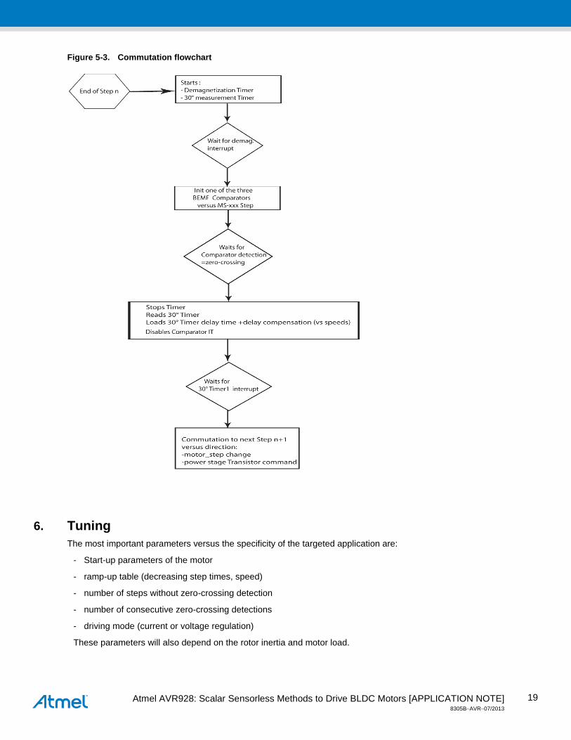
5.3.1 Thirty degree phase angle and Demagnetization At the end of a commutation step, the active switch is open. At this moment, due to the inductance of the motor coil, a -Ldi/dt voltage pulse is generated. This demagnetization is achieved through the diodes of the bridge.
The demagnetization time will mask the zero-crossing detection during the discharge of this pulse produced at the end of a step.
As described in 4.3.2 (30° phase angle), at end of a commutation step “n”, a 30° angle shift is achieved to calculate the time of next commutation step “n+1”.
A process including the mask time and the 30° shift is started at end of a step. The flowchart of this process is described below:
Atmel AVR928: Scalar Sensorless Methods to Drive BLDC Motors [APPLICATION NOTE] 8305B−AVR−07/2013
19
Figure 5-3. Commutation flowchart
6. Tuning The most important parameters versus the specificity of the targeted application are:
- Start-up parameters of the motor
- ramp-up table (decreasing step times, speed)
- number of steps without zero-crossing detection
- number of consecutive zero-crossing detections
- driving mode (current or voltage regulation)
These parameters will also depend on the rotor inertia and motor load.
Atmel AVR928: Scalar Sensorless Methods to Drive BLDC Motors [APPLICATION NOTE] 8305B−AVR−07/2013
20
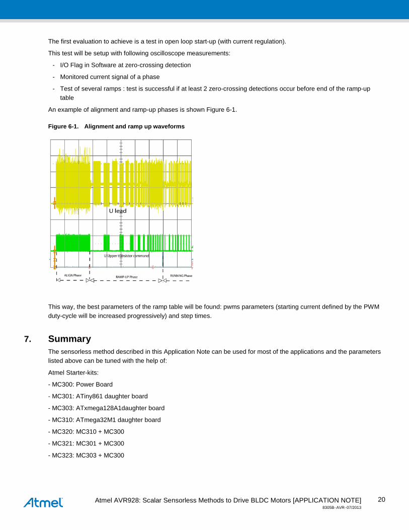
The first evaluation to achieve is a test in open loop start-up (with current regulation).
This test will be setup with following oscilloscope measurements:
- I/O Flag in Software at zero-crossing detection
- Monitored current signal of a phase
- Test of several ramps : test is successful if at least 2 zero-crossing detections occur before end of the ramp-up table
An example of alignment and ramp-up phases is shown Figure 6-1.
Figure 6-1. Alignment and ramp up waveforms
This way, the best parameters of the ramp table will be found: pwms parameters (starting current defined by the PWM duty-cycle will be increased progressively) and step times.
7. Summary The sensorless method described in this Application Note can be used for most of the applications and the parameters listed above can be tuned with the help of:
Atmel Starter-kits:
- MC300: Power Board
- MC301: ATiny861 daughter board
- MC303: ATxmega128A1daughter board
- MC310: ATmega32M1 daughter board
- MC320: MC310 + MC300
- MC321: MC301 + MC300
- MC323: MC303 + MC300
Atmel AVR928: Scalar Sensorless Methods to Drive BLDC Motors [APPLICATION NOTE] 8305B−AVR−07/2013
21
The following Atmel Application Notes provide information and examples for BLDC Sensorless control with Atmel products:
- AVR172 : ATmega32M1
- AVR444 : ATmega48, ATmega88 and ATmega168
- AVR493 : AT90PWM3B
- AVR498 : ATiny261
8. Revision History Doc. Rev. Date Comments
8305B 07/2013 Error correction and new document template
8305A 05/2010 Initial document release
Atmel Corporation 1600 Technology Drive San Jose, CA 95110 USA Tel: (+1)(408) 441-0311 Fax: (+1)(408) 487-2600 www.atmel.com
Atmel Asia Limited Unit 01-5 & 16, 19F BEA Tower, Millennium City 5 418 Kwun Tong Road Kwun Tong, Kowloon HONG KONG Tel: (+852) 2245-6100 Fax: (+852) 2722-1369
Atmel Munich GmbH Business Campus Parkring 4 D-85748 Garching b. Munich GERMANY Tel: (+49) 89-31970-0 Fax: (+49) 89-3194621
Atmel Japan G.K. 16F Shin-Osaki Kangyo Building 1-6-4 Osaki Shinagawa-ku, Tokyo 141-0032 JAPAN Tel: (+81)(3) 6417-0300 Fax: (+81)(3) 6417-0370
© 2013 Atmel Corporation. All rights reserved. / Rev.: 8305B−AVR−07/2013
Atmel®, logo and combinations thereof Enabling Unlimited Possibilities®, AVR®, and others are registered trademarks or trademarks of Atmel Corporation or its subsidiaries. Other terms and product names may be trademarks of others.
Disclaimer: The information in this document is provided in connection with Atmel products. No license, express or implied, by estoppel or otherwise, to any intellectual property right is granted by this document or in connection with the sale of Atmel products. EXCEPT AS SET FORTH IN THE ATMEL TERMS AND CONDITIONS OF SALES LOCATED ON THE ATMEL WEBSITE, ATMEL ASSUMES NO LIABILITY WHATSOEVER AND DISCLAIMS ANY EXPRESS, IMPLIED OR STATUTORY WARRANTY RELATING TO ITS PRODUCTS INCLUDING, BUT NOT LIMITED TO, THE IMPLIED WARRANTY OF MERCHANTABILITY, FITNESS FOR A PARTICULAR PURPOSE, OR NON-INFRINGEMENT. IN NO EVENT SHALL ATMEL BE LIABLE FOR ANY DIRECT, INDIRECT, CONSEQUENTIAL, PUNITIVE, SPECIAL OR INCIDENTAL DAMAGES (INCLUDING, WITHOUT LIMITATION, DAMAGES FOR LOSS AND PROFITS, BUSINESS INTERRUPTION, OR LOSS OF INFORMATION) ARISING OUT OF THE USE OR INABILITY TO USE THIS DOCUMENT, EVEN IF ATMEL HAS BEEN ADVISED OF THE POSSIBILITY OF SUCH DAMAGES. Atmel makes no representations or warranties with respect to the accuracy or completeness of the contents of this document and reserves the right to make changes to specifications and products descriptions at any time without notice. Atmel does not make any commitment to update the information contained herein. Unless specifically provided otherwise, Atmel products are not suitable for, and shall not be used in, automotive applications. Atmel products are not intended, authorized, or warranted for use as components in applications intended to support or sustain life.
Related Documents