1 Governors America Corp. © 2020 Copyright All Rights Reserved ATB Series Integral Throttle Actuator 3-2020-K1 PIB 2080 ATB Series Integral Throttle Body Actuators 1 INTRODUCTION The ATB Series integral throttle body electric actuators are designed to control the air or air/fuel mixture to a gas or gaseous-fueled engine. They are typically used to control an engine by working in tandem with a con- ventional fuel mixer. • Cost-effective, maintenance-free, compact design • Rapid response to transient load condition • Sealed to 5.0 bar • Mounts in any position; no mechanical linkage, no mounting brack- ets • Flexible design for engine, manifold, and fuel mixer considerations • Idle and max adjustment screws • Optional high temperature and corrosive environmental conditions ATB401T1F-24 ATB652T2N14-12 ATB552T2N14-24 SAMPLE ATB CONFIGURATIONS ATB85T4F14-24 2 CONFIGURATION NOMENCLATURE SUFFIX DEFINITION 1 4 High Temperature, Sealed 2 Mechanical Position indicator, Sealed (Only available with non-high-temp version, T2 units only) F Feedback Position Sensor, Sealed N Normal (Comes with no Feedback Position Sensor), Sealed PART NO. SYMBOL(S) DEFINITION ATB452T2N-12 N Does not include Feedback Position Sensor. Sealed to 5.0 Bar. ATB452T2N2-12 N,2 Does not include Feedback Position Sensor, but has a mechanical position indicator. Sealed to 5.0 Bar ATB753T3F14-24 F,1,4 Includes Feedback Position Sensor, high temperature rated, sealed to 5.0 Bar internally. Examples: AVAILABLE BORE SIZES BY FAMILY BORE DIAMETERS FAMILY 25, 30, 35, 40 T1 45, 55, 65 T2 75, 85 ,95 T4 • All gaseous fueled engines need a positive fuel lockout that should be of the electrical variety. • Throttle bodies will operate without electrical power. • Gaseous fueled engines will retain unburnt fuel internally especially propane.

Welcome message from author
This document is posted to help you gain knowledge. Please leave a comment to let me know what you think about it! Share it to your friends and learn new things together.
Transcript
1
Governors America Corp. © 2020 Copyright All Rights ReservedATB Series Integral Throttle Actuator 3-2020-K1 PIB 2080
ATB SeriesIntegral Throttle Body Actuators
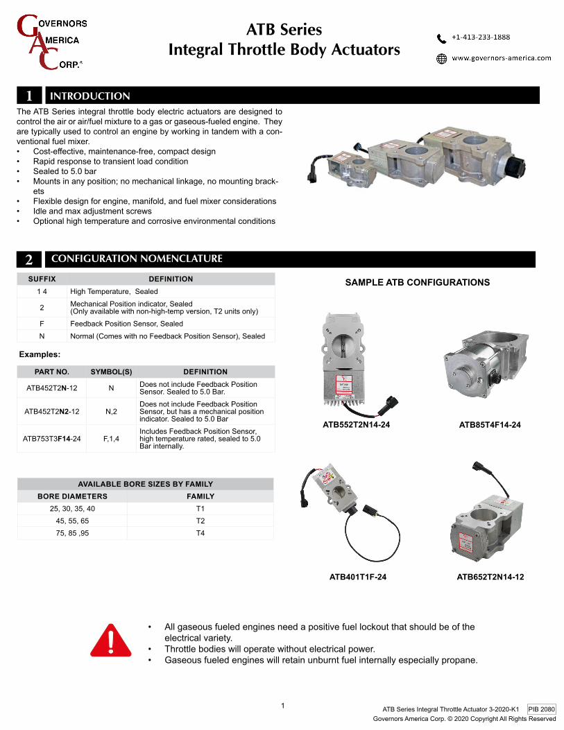
1 InTroducTIonThe ATB Series integral throttle body electric actuators are designed to control the air or air/fuel mixture to a gas or gaseous-fueled engine. They are typically used to control an engine by working in tandem with a con-ventional fuel mixer. • Cost-effective,maintenance-free,compactdesign• Rapid response to transient load condition• Sealed to 5.0 bar• Mountsinanyposition;nomechanicallinkage,nomountingbrack-
ets• Flexibledesignforengine,manifold,andfuelmixerconsiderations• Idle and max adjustment screws• Optional high temperature and corrosive environmental conditions
ATB401T1F-24 ATB652T2N14-12
ATB552T2N14-24
SAMPLE ATB CONFIGURATIONS
ATB85T4F14-24
2 confIgurATIon nomenclATure
SUFFIX DEFINITION1 4 HighTemperature,Sealed
2 MechanicalPositionindicator,Sealed(Onlyavailablewithnon-high-tempversion,T2unitsonly)
F FeedbackPositionSensor,SealedN Normal(ComeswithnoFeedbackPositionSensor),Sealed
PART NO. SYMBOL(S) DEFINITION
ATB452T2N-12 N Does not include Feedback Position Sensor. Sealed to 5.0 Bar.
ATB452T2N2-12 N,2Does not include Feedback Position Sensor,buthasamechanicalpositionindicator. Sealed to 5.0 Bar
ATB753T3F14-24 F,1,4IncludesFeedbackPositionSensor,hightemperaturerated,sealedto5.0Bar internally.
Examples:
AvAILABLE BORE SIzES BY FAMILY BORE DIAMETERS FAMILY
25,30,35,40 T145,55,65 T275,85,95 T4
• All gaseous fueled engines need a positive fuel lockout that should be of the electrical variety.
• Throttle bodies will operate without electrical power. • Gaseous fueled engines will retain unburnt fuel internally especially propane.
2
Governors America Corp. © 2020 Copyright All Rights ReservedATB Series Integral Throttle Actuator 3-2020-K1 PIB 2080
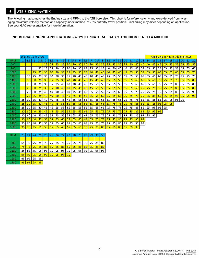
3 ATB SIZIng mATrIX
INDUSTRIAL ENGINE APPLICATIONS / 4 CYCLE / NATURAL GAS / STOIChIOMETRIC FA MIXTURE
The following matrix matches the Engine size and RPMs to the ATB bore size. This chart is for reference only and were derived from aver-agingmaximumvelocitymethodandcapacityindexmethodat75%butterflytravelposition.Finalsizingmaydifferdependingonapplication.See your GAC representative for more information.
3
Governors America Corp. © 2020 Copyright All Rights ReservedATB Series Integral Throttle Actuator 3-2020-K1 PIB 2080
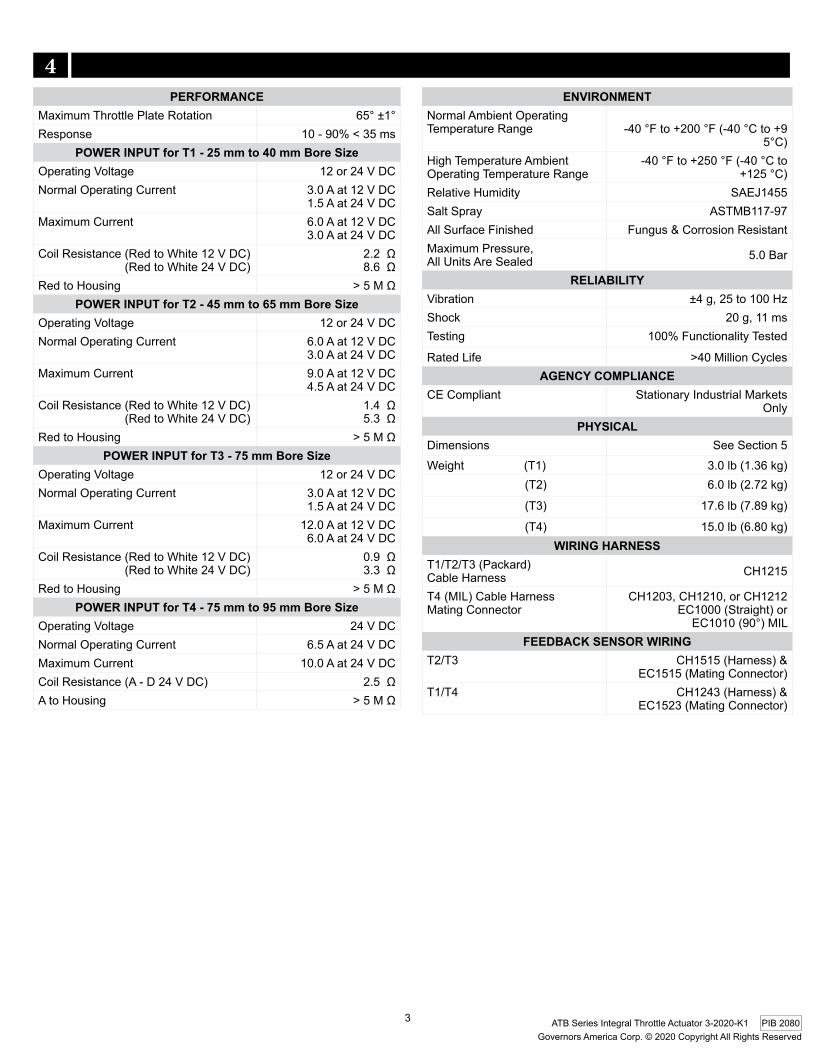
PERFORMANCEMaximum Throttle Plate Rotation 65°±1°Response 10-90%<35ms
POWER INPUT for T1 - 25 mm to 40 mm Bore SizeOperating Voltage 12 or 24 V DC Normal Operating Current 3.0 A at 12 V DC
1.5 A at 24 V DCMaximum Current 6.0Aat12VDC
3.0 A at 24 V DCCoilResistance(RedtoWhite12VDC)(RedtoWhite24VDC)
2.2Ω8.6Ω
Red to Housing >5MΩPOWER INPUT for T2 - 45 mm to 65 mm Bore Size
Operating Voltage 12 or 24 V DC Normal Operating Current 6.0Aat12VDC
3.0 A at 24 V DCMaximum Current 9.0Aat12VDC
4.5 A at 24 V DCCoilResistance(RedtoWhite12VDC)(RedtoWhite24VDC)
1.4Ω5.3Ω
Red to Housing >5MΩPOWER INPUT for T3 - 75 mm Bore Size
Operating Voltage 12 or 24 V DC Normal Operating Current 3.0 A at 12 V DC
1.5 A at 24 V DCMaximum Current 12.0 A at 12 V DC
6.0Aat24VDCCoilResistance(RedtoWhite12VDC)(RedtoWhite24VDC)
0.9Ω3.3Ω
Red to Housing >5MΩPOWER INPUT for T4 - 75 mm to 95 mm Bore Size
Operating Voltage 24 V DC Normal Operating Current 6.5Aat24VDCMaximum Current 10.0 A at 24 V DCCoilResistance(A-D24VDC) 2.5ΩA to Housing >5MΩ
ENvIRONMENTNormal Ambient Operating Temperature Range -40°Fto+200°F(-40°Cto+9
5°C)High Temperature Ambient Operating Temperature Range
-40°Fto+250°F(-40°Cto+125°C)
Relative Humidity SAEJ1455Salt Spray ASTMB117-97All Surface Finished Fungus & Corrosion ResistantMaximumPressure,All Units Are Sealed 5.0 Bar
RELIABILITYVibration ±4g,25to100HzShock 20g,11msTesting 100% Functionality Tested
Rated Life >40 Million CyclesAGENCY COMPLIANCE
CE Compliant Stationary Industrial Markets Only
PhYSICALDimensions See Section 5Weight(T1) 3.0lb(1.36kg)
(T2) 6.0lb(2.72kg)
(T3) 17.6lb(7.89kg)
(T4) 15.0lb(6.80kg)WIRING hARNESS
T1/T2/T3(Packard)Cable Harness CH1215
T4(MIL)CableHarnessMating Connector
CH1203,CH1210,orCH1212EC1000(Straight)or
EC1010(90°)MILFEEDBACK SENSOR WIRING
T2/T3 CH1515(Harness)&EC1515(MatingConnector)
T1/T4 CH1243(Harness)&EC1523(MatingConnector)
SPecIfIcATIonS4
4
Governors America Corp. © 2020 Copyright All Rights ReservedATB Series Integral Throttle Actuator 3-2020-K1 PIB 2080
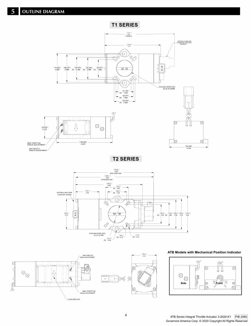
5 ouTlIne dIAgrAm
MIN THROTTLE
AVAILABLE BORE SIZES:
134.85.31
175.76.92
FEEDBACK
OPTIONAL COVER AND CONNECTOR USED WITH
FEEDBACK
T1 SERIES
MIN THROTTLE
AVAILABLE BORE SIZES:
134.85.31
175.76.92
FEEDBACK
OPTIONAL COVER AND CONNECTOR USED WITH
FEEDBACK
MIN THROTTLE
AVAILABLE BORE SIZES:
134.85.31
175.76.92
FEEDBACK
OPTIONAL COVER AND CONNECTOR USED WITH
FEEDBACK
2.3860.3
2.8873.0
2.8873.0
2.3860.3
3.5690.5
AVAILABLE BORE SIZES:45, 55, 65 MM
4.56115.9
3.7695.4
2.9474.7
.4812.3
.236.0
.317.9
9.69STANDARD UNIT
246.1
3.7595.3
9.95HIGH TEMP UNIT
252.8
COVER NOT SHOWN
ANGLE ADJUSTMENT MIN THROTTLE
ANGLE ADJUSTMENT
FLOW DIRECTION
3.1279.2
8.08205.2
OPTIONAL HIGH TEMP
ATB Models with Mechanical Position Indicator
Side
T2 SERIES
2.3860.3
2.8873.0
2.8873.0
2.3860.3
3.5690.5
AVAILABLE BORE SIZES:45, 55, 65 MM
4.56115.9
3.7695.4
2.9474.7
.4812.3
.236.0
.317.9
9.69STANDARD UNIT
246.1
3.7595.3
9.95HIGH TEMP UNIT
252.8
COVER NOT SHOWN
ANGLE ADJUSTMENT MIN THROTTLE
ANGLE ADJUSTMENT
FLOW DIRECTION
3.1279.2
8.08205.2
OPTIONAL HIGH TEMP
2.3860.3
2.8873.0
2.8873.0
2.3860.3
3.5690.5
AVAILABLE BORE SIZES:45, 55, 65 MM
4.56115.9
3.7695.4
2.9474.7
.4812.3
.236.0
.317.9
9.69STANDARD UNIT
246.1
3.7595.3
9.95HIGH TEMP UNIT
252.8
COVER NOT SHOWN
ANGLE ADJUSTMENT MIN THROTTLE
ANGLE ADJUSTMENT
FLOW DIRECTION
3.1279.2
8.08205.2
OPTIONAL HIGH TEMP
Front
5
Governors America Corp. © 2020 Copyright All Rights ReservedATB Series Integral Throttle Actuator 3-2020-K1 PIB 2080
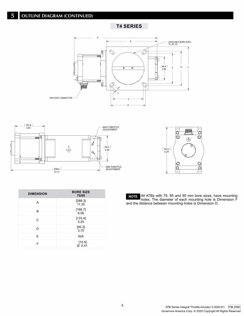
AllATBswith75,85and95mmboresizes,havemountingholes. The diameter of each mounting hole is Dimension F
and the distance between mounting holes is Dimension D.
NOTE
D
308.612.15
90.53.56
102.94.05 MAX THROTTLE
ADJUSTMENT
MIN THROTTLE ADJUSTMENT
162.26.39
86.43.40
AVAILABLE BORE SIZES:75, 85, 95, 110, 120 mm
MILITARY CONNECTORDim. Bore Size 85/95 110/120
A 11.35 12.15 [288.3] [308.6]
B [ 166.7] [189.2]
C 5.25 6.39 [133.4] [162.2]
D 3.75 5.05 [95.2] [128.3]
E N/A 4.45 [113.0]
F R= 0.41 0.42 [10.5] [10.8]
6.56 7.45
A
B
C
D
E
E
F
DIMENSION BORE SIzE75/95
A [288.3]11.35
B [166.7]6.56
C [133.4]5.25
D [95.2]3.75
E N/A
F [10.5] Ø 0.41
T4 SERIES
D
308.612.15
90.53.56
102.94.05 MAX THROTTLE
ADJUSTMENT
MIN THROTTLE ADJUSTMENT
162.26.39
86.43.40
AVAILABLE BORE SIZES:75, 85, 95, 110, 120 mm
MILITARY CONNECTORDim. Bore Size 85/95 110/120
A 11.35 12.15 [288.3] [308.6]
B [ 166.7] [189.2]
C 5.25 6.39 [133.4] [162.2]
D 3.75 5.05 [95.2] [128.3]
E N/A 4.45 [113.0]
F R= 0.41 0.42 [10.5] [10.8]
6.56 7.45
A
B
C
D
E
E
F
D
308.612.15
90.53.56
102.94.05 MAX THROTTLE
ADJUSTMENT
MIN THROTTLE ADJUSTMENT
162.26.39
86.43.40
AVAILABLE BORE SIZES:75, 85, 95, 110, 120 mm
MILITARY CONNECTORDim. Bore Size 85/95 110/120
A 11.35 12.15 [288.3] [308.6]
B [ 166.7] [189.2]
C 5.25 6.39 [133.4] [162.2]
D 3.75 5.05 [95.2] [128.3]
E N/A 4.45 [113.0]
F R= 0.41 0.42 [10.5] [10.8]
6.56 7.45
A
B
C
D
E
E
F
5 ouTlIne dIAgrAm (conTInued)

6
Governors America Corp. © 2020 Copyright All Rights ReservedATB Series Integral Throttle Actuator 3-2020-K1 PIB 2080
6 InSTAllATIonThe actuator is mounted rigidly between the engine’s intake manifold and the gas mixer. The preferred mounting orientation for the ATB Se-ries is with the throttle shaft parallel to the engine crank shaft. Normal vibrationfromtheenginewillnotaffecttheoperationoftheactuator.
TheATBSeriesisdesignedtoprovideanexactfittothevariousman-ifolds and mixers available. Section 5 OUTLINE DIAGRAM shows prop-er sizing of the ATB to the engine for envelope concerns.
NOTE
7 WIrIngAll throttle body actuators are prewired for either 12 or 24 V DC systems. Use the included wiring harness to connect the actuator to the speed controlunit’soutputterminals.Priortoconnectingtheactuatorcable,twistitsothatthereisaboutonecompletetwistper1.0in[25.4mm]alongtheentirelengthofthecable.ThiswillsubstantiallyreduceEMIeffectsonthecontrolsystem.ForapplicationswhereEMIisstillaconcern,shielded cable for the actuator is recommended.
Packard Connector(T1, T2 &T3)
MIL Connector(ATB T4)
AB
CD
E
F
to Actuator Terminal “A”on Speed Control Unit
to Actuator Terminal “B”on Speed Control Unit
hARNESSPIN SIGNAL1 +5V2 GND4 OUT
hARNESSPIN SIGNALA +5VB GNDC OUT
AB
CD
F
E
ToControl Unit
12 VOLT OPERATIONA TO CB TO DA AND D TO ACTUATOR TERMINALS OF SPEED CONTROL UNIT
ACB295C & ACB295H WIRING
AB
CD
F
ETo
Control Unit
24 VOLT OPERATIONB TO CA AND D TO ACTUATOR TERMINALS
AB
C
D
F
E
TO SPEED CONTROL UNIT“ACTUATOR” TERMINALS
TO SPEED CONTROL UNIT“POSITION SENSOR” TERMINALS
ACB295F-24 WIRING
ACE275K WIRING
Harness
FEEDBACK SENSOR(Female Receptacle)(ATB T2 &T3)
Mating ConnectorEC1523
Mating ConnectorEC1515
A B C
(ATB T1 & T4)
The Position Feedback Sensor is installed and preset at no fuel (0%)at1.0Voutput.Maximumopening (100%)at65°is3.8V.
NOTE
POSITION FEEDBACK SENSOR
A B
Naturally Aspirated Engines Turbocharged-Intercooled Engines
Engine
ATB
Speed Control
Exhaust
Air�lter
Gas
Ring Gear
Engine
ATB
Turbocharger
Exhaust
Mixer
Air�lter
Gas
Intercooler
Ring Gear
Speed Control
A Gaseous Fuel Shut-Off Valve, Independent of theThrottleBodyActuator,ShouldBeProvidedtoPreventLoss of Engine Control or Propagation of a Hazardous Flammable Condition Which May Cause Personal Inju-ry or Equipment Damage.
Anoverspeedshutdowndevice,independentofthegovernorsystem,shouldbeprovidedtopreventlossofenginecontrol,whichmaycausepersonalinjury.
The arrow on the side of the ATB represents thedirectionofflow.
7
Governors America Corp. © 2020 Copyright All Rights ReservedATB Series Integral Throttle Actuator 3-2020-K1 PIB 2080
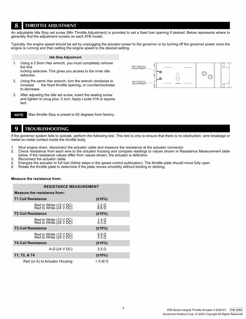
8 ThroTTle AdjuSTmenTAnadjustableIdleStopsetscrew(MinThrottleAdjustment)isprovidedtosetafixedfuelopeningifdesired.BelowrepresentswheretogenerallyfindtheadjustmentscrewsoneachATBmodel.
Typically,theenginespeedshouldbesetbyunpluggingtheactuatorpowertothegovernororbyturningoffthegovernorpoweroncetheengine is running and then setting the engine speed to the desired setting.
MaxthrottleStopispresetto65degreesfromfactory.
MAX THROTTLE
MIN THROTTLE
2X
21
FULL RADIUS
FULL RADIUS
21
2X
FULL RADIUS
Idle Stop Adjustment
1. Usinga2.5mmHexwrench,youmustcompletelyremovethefirst locking setscrew. This gives you access to the inner idle setscrew.
2. UsingthesameHexwrench,turnthewrenchclockwisetoincreasethefixedthrottleopening,orcounterclockwiseto decrease.
3. AfteradjustingtheIdlesetscrew,insertthesealingscrewandtightentosnugplus¼turn.ApplyLocite518orequiva-lent.
NOTE
9 TrouBleShooTIngIfthegovernorsystemfailstooperate,performthefollowingtest.Thistestisonlytoensurethatthereisnoobstruction,wirebreakageormetal-on-metal contact inside the throttle body.
1. Shutenginedown,disconnecttheactuatorcableandmeasuretheresistanceattheactuatorconnector.2. Check resistance from each wire to the actuator housing and compare readings to values shown in Resistance Measurement table
below.Iftheresistancevaluesdifferfromvaluesshown,theactuatorisdefective.3. Reconnect the actuator cable. 4. Energizetheactuatortofullfuel(followstepsinthespeedcontrolpublication).Thethrottleplateshouldmovefullyopen.5. Rotate the throttle plate to determine if the plate moves smoothly without binding or sticking.
Measure the resistance from:
RESISTANCE MEASUREMENTMeasure the resistance from:T1 Coil Resistance (±10%)
RedtoWhite(12VDC)RedtoWhite(24VDC)
2.2Ω8.6Ω
T2 Coil Resistance (±10%)RedtoWhite(12VDC)RedtoWhite(24VDC)
1.4Ω5.3Ω
T3 Coil Resistance (±10%)RedtoWhite(12VDC)RedtoWhite(24VDC)
0.9Ω3.3Ω
T4 Coil Resistance (±10%)A-D(24VDC) 2.5Ω
T1, T2, & T4 (±10%)Red(orA)toActuatorHousing >5MΩ
Related Documents