“Assemble a CNC drilling head to a milling machine" Author: CARLOS SANCHEZ CRISTOBAL Mechatronics Engineering HZ Supervisor Mr. L.J.M Janssen Timesavers International B.V Supervisor: Mr. Theo Kannekens

Welcome message from author
This document is posted to help you gain knowledge. Please leave a comment to let me know what you think about it! Share it to your friends and learn new things together.
Transcript
“Assemble a CNC drilling head to a
milling machine"
Author: CARLOS SANCHEZ CRISTOBAL
Mechatronics Engineering HZ Supervisor Mr. L.J.M Janssen
Timesavers International B.V Supervisor: Mr. Theo Kannekens
ASSEMBLE A CNC DRILLING HEAD TO A MILLING MACHINE
2
“Assemble a CNC drilling head to a milling machine" Author: Carlos Sánchez Cristóbal
Vlissingen, the Netherlands
June 2010
Company: Timesavers International B.V
Manufacturer of widebelt abrasive machines
Goes, the Netherlands
Area: Mechatronics Engineering
HZ Supervisor Mr. L.J.M Janssen
Timesavers International B.V Supervisor: Mr. Theo Kannekens
Approval
Carlos Sanchez Cristobal Mr. Theo Kannekens Mr. L.J.M Janssen Project Author Company mentor HZ Tutor

ASSEMBLE A CNC DRILLING HEAD TO A MILLING MACHINE
3
FOREWORD I am grateful to Paul Hartendorp for the opportunity to start my professional career for Timesavers International B.V. Likewise, I am very grateful to Mr.Theo Kannekens who has let me be in charge of this project. Finally, I am grateful to both Rod Kregeler and all the persons who have helped me in order to achieve the purpose of the project.
Thanks!! I won´t forget you

ASSEMBLE A CNC DRILLING HEAD TO A MILLING MACHINE
4
SUMMARY The topic of the project is related to the field of the Engineering. Throughout this report, the author will develop issues where mechanical, electrical and electronic knowledge will have an important role. The content is divided into several chapters that let go in depth in these branches. In the first chapter, it is explained the purpose of the project. Basically, it involves the possibility to join two machines .Moreover, the process that is carried out by one of the machines is going to be controlled by a computer. The second chapter let introduce the company .This information let the reader has an overview of the business sector in which the project is developed. In Chapter three, the author explains the working principle of the machines. Next, a design process is developed in order to find the best way to assemble the machines. The mechanical knowledge has the main role in this phase. The reader will be led to the final decision by means of the sequential steps of the process. Chapter five will be based on the needed modifications on the machines to make possible the proper working of both of them when are assembled. In the next chapter, it will be showed both the electrical and electronic devices that will let the coordination between the machines. The reader will get information about the new equipment. It will involve the need to create new electrical diagrams in order to achieve a proper installation. In the last chapter, it will be showed the steps to develop a program that let control the process of the machine.
ASSEMBLE A CNC DRILLING HEAD TO A MILLING MACHINE
5
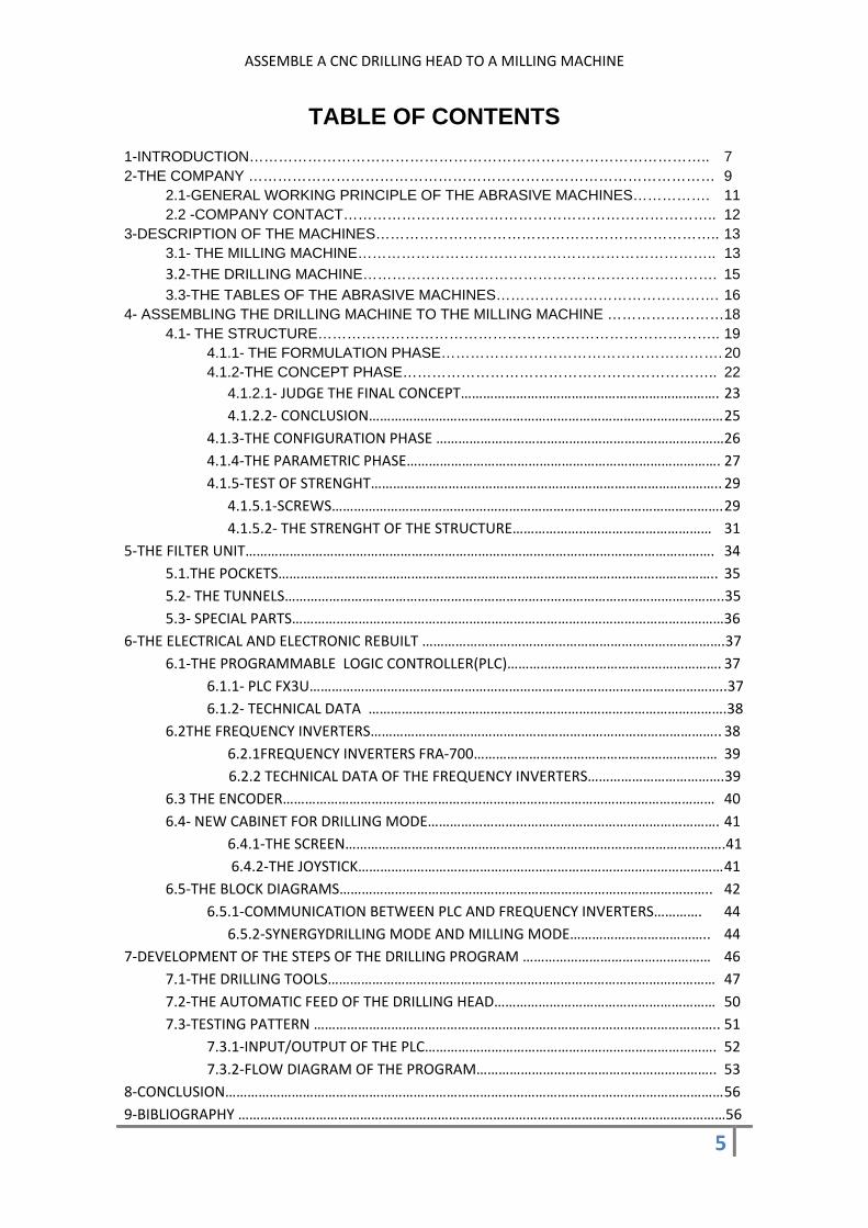
TABLE OF CONTENTS
1-INTRODUCTION………………………………………………………………………………….. 7 2-THE COMPANY …………………………………………………………………………………… 9 2.1-GENERAL WORKING PRINCIPLE OF THE ABRASIVE MACHINES……………. 11 2.2 -COMPANY CONTACT………………………………………………………………….. 12 3-DESCRIPTION OF THE MACHINES…………………………………………………………….. 13 3.1- THE MILLING MACHINE……………………………………………………………….. 13 3.2-THE DRILLING MACHINE………………………………………………………………. 15 3.3-THE TABLES OF THE ABRASIVE MACHINES………………………………………. 16 4- ASSEMBLING THE DRILLING MACHINE TO THE MILLING MACHINE ……………………18 4.1- THE STRUCTURE……………………………………………………………………….. 19 4.1.1- THE FORMULATION PHASE…………………………………………………. 20 4.1.2-THE CONCEPT PHASE……………………………………………………….. 22 4.1.2.1- JUDGE THE FINAL CONCEPT……………………………………………………………. 23 4.1.2.2‐ CONCLUSION…………………………………………………………………………………… 25 4.1.3‐THE CONFIGURATION PHASE ……………………………………………………………………26 4.1.4‐THE PARAMETRIC PHASE…………………………………………………………………………. 27 4.1.5‐TEST OF STRENGHT………………………………………………………………………………….. 29 4.1.5.1‐SCREWS……………………………………………………………………………………………. 29 4.1.5.2‐ THE STRENGHT OF THE STRUCTURE……………………………………………… 31 5‐THE FILTER UNIT………………………………………………………………………………………………………………. 34 5.1.THE POCKETS……………………………………………………………………………………………………….. 35 5.2‐ THE TUNNELS………………………………………………………………………………………………………..35 5.3‐ SPECIAL PARTS………………………………………………………………………………………………………36 6‐THE ELECTRICAL AND ELECTRONIC REBUILT ……………………………………………………………………….37 6.1‐THE PROGRAMMABLE LOGIC CONTROLLER(PLC)…………………………………………………. 37 6.1.1‐ PLC FX3U…………………………………………………………………………………………………..37 6.1.2‐ TECHNICAL DATA …………………………………………………………………………………….38 6.2THE FREQUENCY INVERTERS………………………………………………………………………………….. 38 6.2.1FREQUENCY INVERTERS FRA‐700………………………………………………………… 39 6.2.2 TECHNICAL DATA OF THE FREQUENCY INVERTERS……………………………….39 6.3 THE ENCODER……………………………………………………………………………………………………… 40 6.4‐ NEW CABINET FOR DRILLING MODE……………………………………………………………………. 41 6.4.1‐THE SCREEN………………………………………………………………………………………….41 6.4.2‐THE JOYSTICK……………………………………………………………………………………… 41 6.5‐THE BLOCK DIAGRAMS……………………………………………………………………………………….. 42 6.5.1‐COMMUNICATION BETWEEN PLC AND FREQUENCY INVERTERS…………. 44 6.5.2‐SYNERGYDRILLING MODE AND MILLING MODE……………………………….. 44 7‐DEVELOPMENT OF THE STEPS OF THE DRILLING PROGRAM …………………………………………… 46 7.1‐THE DRILLING TOOLS…………………………………………………………………………………………… 47 7.2‐THE AUTOMATIC FEED OF THE DRILLING HEAD…………………………………………………… 50 7.3‐TESTING PATTERN ……………………………………………………………………………………………….. 51 7.3.1‐INPUT/OUTPUT OF THE PLC……………………………………………………………………. 52 7.3.2‐FLOW DIAGRAM OF THE PROGRAM……………………………………………………….. 53 8‐CONCLUSION……………………………………………………………………………………………………………………… 56 9‐BIBLIOGRAPHY ……………………………………………………………………………………………………………………56

ASSEMBLE A CNC DRILLING HEAD TO A MILLING MACHINE
6
10‐APPENDICES…………………………………………………………………………………………………………………… 57 10.1‐Appendix 1”Calculation of the screws”………………………………………………………………. 57 10.2‐Appendix 2 ”Strength of the structure” ……………………………………………………………….61 10.3‐Appendix 3 ”Flow diagram”.......................................................................................66
ASSEMBLE A CNC DRILLING HEAD TO A MILLING MACHINE
7
1 INTRODUCTION
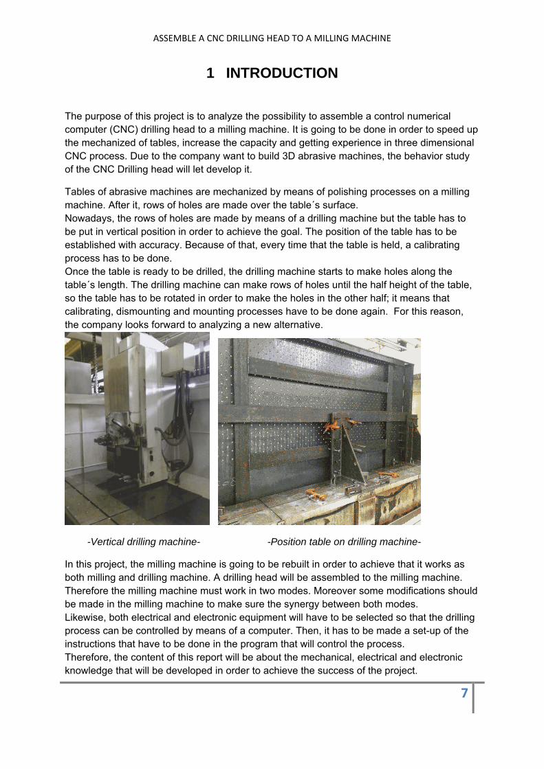
The purpose of this project is to analyze the possibility to assemble a control numerical computer (CNC) drilling head to a milling machine. It is going to be done in order to speed up the mechanized of tables, increase the capacity and getting experience in three dimensional CNC process. Due to the company want to build 3D abrasive machines, the behavior study of the CNC Drilling head will let develop it.
Tables of abrasive machines are mechanized by means of polishing processes on a milling machine. After it, rows of holes are made over the table´s surface. Nowadays, the rows of holes are made by means of a drilling machine but the table has to be put in vertical position in order to achieve the goal. The position of the table has to be established with accuracy. Because of that, every time that the table is held, a calibrating process has to be done. Once the table is ready to be drilled, the drilling machine starts to make holes along the table´s length. The drilling machine can make rows of holes until the half height of the table, so the table has to be rotated in order to make the holes in the other half; it means that calibrating, dismounting and mounting processes have to be done again. For this reason, the company looks forward to analyzing a new alternative.
-Vertical drilling machine- -Position table on drilling machine-
In this project, the milling machine is going to be rebuilt in order to achieve that it works as both milling and drilling machine. A drilling head will be assembled to the milling machine. Therefore the milling machine must work in two modes. Moreover some modifications should be made in the milling machine to make sure the synergy between both modes. Likewise, both electrical and electronic equipment will have to be selected so that the drilling process can be controlled by means of a computer. Then, it has to be made a set-up of the instructions that have to be done in the program that will control the process. Therefore, the content of this report will be about the mechanical, electrical and electronic knowledge that will be developed in order to achieve the success of the project.

ASSEMBLE A CNC DRILLING HEAD TO A MILLING MACHINE
8
Throughout this report, the reader will go in depth on issues like the machines’ working principle and the mechanical way to assemble the drilling head to the milling machine. In the same way, the needed modifications to achieve the synergy will be explained. Moreover, the development of the steps that will be followed by the program to make the holes according to the different worktables’ patterns will be showed.
ASSEMBLE A CNC DRILLING HEAD TO A MILLING MACHINE
9
2 THE COMPANY Timesavers International B.V was established in Goes (The Netherlands) in 1996 as part of Timesavers Group whose business are focus on the manufacturing of wide belt abrasive machines over last seventy years.
-Picture2.1. Headquarter of Timesavers on Goes (The Netherlands)-
Nowadays, Timesavers International B.V manufactures tailor made machines for the stainless steel market under the brand name "Timesavers by Grindingmaster”. In fact, it is "The world market leader in wide belt grinding machines for metal applications.”
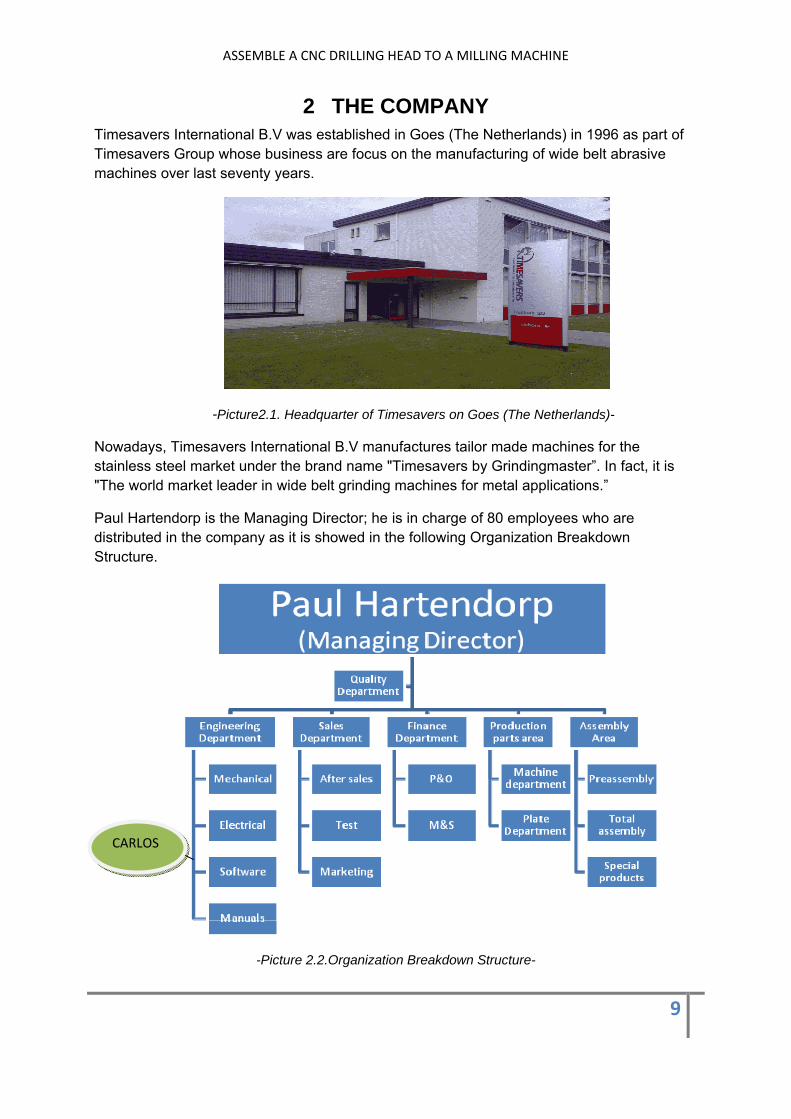
Paul Hartendorp is the Managing Director; he is in charge of 80 employees who are distributed in the company as it is showed in the following Organization Breakdown Structure.
-Picture 2.2.Organization Breakdown Structure-
CARLOS

ASSEMBLE A CNC DRILLING HEAD TO A MILLING MACHINE
10
The Engineering department creates machines according to the customer‘s wishes. It starts to become a reality in the production area, where components like tables of abrasive machines and frames among others are built, welded, polished, drilled, etc…
Before components are brought to the assemble area, it is verified that parts achieve the specifications. After it, painting process is necessary for some of them. In the assemble area, new machines start to take form; mechanical parts are assembled.
-Picture 2.3”Assembling mechanical parts”-
Both electrical and electronic devices like frequency inverters, transformers, motors amongst others are integrated on the machines. Once the machine is finished, a quality test has to be done prior to the sale. Finally the machine is shipped to the customer to Russia, Check Republic, Chine, etc…..
-Picture 2.4”Wide belt abrasive machine”
Frame
Rollers
Table
ASSEMBLE A CNC DRILLING HEAD TO A MILLING MACHINE
11
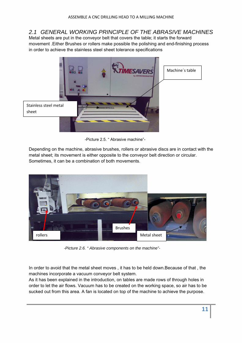
2.1 GENERAL WORKING PRINCIPLE OF THE ABRASIVE MACHINES Metal sheets are put in the conveyor belt that covers the table; it starts the forward movement .Either Brushes or rollers make possible the polishing and end-finishing process in order to achieve the stainless steel sheet tolerance specifications
-Picture 2.5. “ Abrasive machine”-
Depending on the machine, abrasive brushes, rollers or abrasive discs are in contact with the metal sheet; its movement is either opposite to the conveyor belt direction or circular. Sometimes, it can be a combination of both movements.
-Picture 2.6. “ Abrasive components on the machine”-
In order to avoid that the metal sheet moves , it has to be held down.Because of that , the machines incorporate a vacuum conveyor belt system. As it has been explained in the introduction, on tables are made rows of through holes in order to let the air flows. Vacuum has to be created on the working space, so air has to be sucked out from this area. A fan is located on top of the machine to achieve the purpose.
Machine´s table
Stainless steel metal sheet
rollers
Brushes
Metal sheet
ASSEMBLE A CNC DRILLING HEAD TO A MILLING MACHINE
12
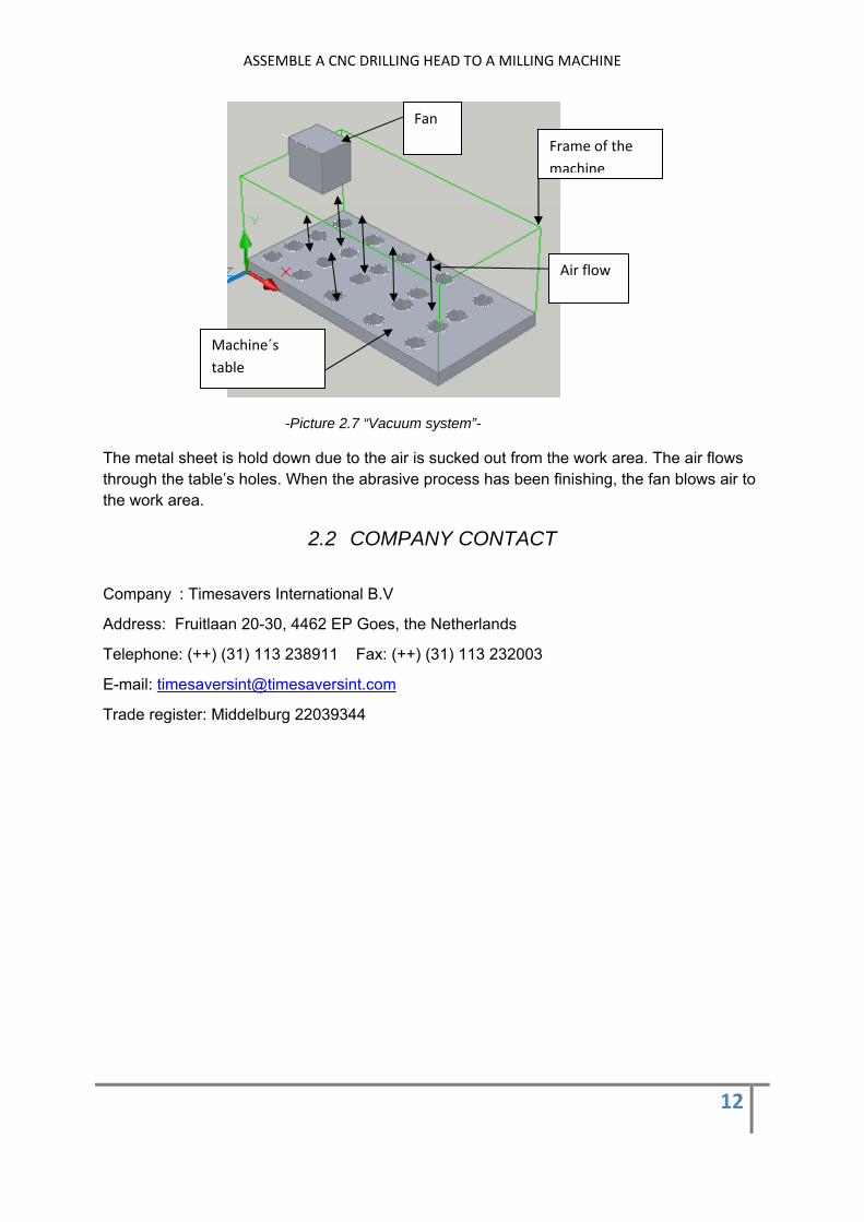
-Picture 2.7 “Vacuum system”-
The metal sheet is hold down due to the air is sucked out from the work area. The air flows through the table’s holes. When the abrasive process has been finishing, the fan blows air to the work area.
2.2 COMPANY CONTACT
Company : Timesavers International B.V
Address: Fruitlaan 20-30, 4462 EP Goes, the Netherlands
Telephone: (++) (31) 113 238911 Fax: (++) (31) 113 232003
E-mail: [email protected]
Trade register: Middelburg 22039344
Fan
Air flow
Machine´s table
Frame of the machine

ASSEMBLE A CNC DRILLING HEAD TO A MILLING MACHINE
13
3 DESCRIPTION OF THE MACHINES As it has been explained on the introduction, the purpose of the project is to assemble a drilling head to a milling machine. An overview of the machines is given in order to understand the working process. Likewise, the tables of the abrasive machines are described.
3.1 THE MILLING MACHINE
The milling machine is in the company since 1975. It is used to carry out polishing processes on parts that become components of new abrasive machines. The machine consists of three heads that are assembled to the bridge. The first one, right side on picture 3.1, is to mill tables and frames among others; the second one is to mill special parts and the third one is a drilling head that is out of service.
-Picture 3.1. ”Milling machine”-
The horizontal movement of the heads along the bridge is by means of DC motors (Picture 3.2 ) that is located on the right top of the machine. One of the motors is for fast speed and the second one let the speed regulation according to the working process. The three heads are assembled to the bridge by means of plates. Each plate has mechanical connections with two spindles (Picture 3.3). One is for the horizontal movement of the head along the bridge, the second one is common for all of them, and it is for the height regulation of the head’s tools. Depending on the head that has to be moved, four handles make activate whatever is desired.
Bridge
Worktable
Three heads
Tool
123

ASSEMBLE A CNC DRILLING HEAD TO A MILLING MACHINE
14
-Picture3.2 ”Four hand bars control the spindles”- -Picture 3.3 “Plate-Spindles connection”-
The vertical movement of the bridge is controlled by a motor located on the top of the machine. Initially the bridge is immobilized by means of a clamp. A pump let move the bridge, when the pressure is proper. Then the clamp is opened and a micro switch sends the signal to the motor .Finally, the bridge starts to move either up or down.
- Picture 3.4 “ Two spindles guide the up/down movement of the bridge”-
Likewise, the milling machine’s worktable is driven by means of two AC motors. Both of them make possible the forward and backward movement of the worktable. One of them is for fast speed and the second one let choose between low and high speed depend on the working process.
Plate
Bridge
Two spindles
Motor
1.5Kw
Vertical spindles
Hand bars
ASSEMBLE A CNC DRILLING HEAD TO A MILLING MACHINE
15
-Picture3.5”Ac motors drive the milling machine’s worktable -
Finally , in order to make easier the movement of the worktable,180 oil liters are stored on the back part of the milling machine. A pump makes the oil flow through the canals in order to achieve it.
3.2 THE DRILLING MACHINE
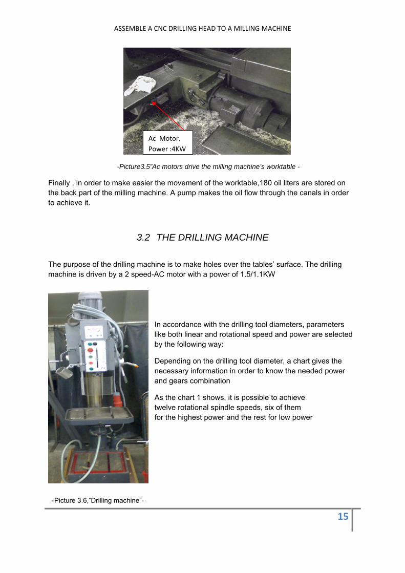
The purpose of the drilling machine is to make holes over the tables’ surface. The drilling machine is driven by a 2 speed-AC motor with a power of 1.5/1.1KW
In accordance with the drilling tool diameters, parameters like both linear and rotational speed and power are selected by the following way:
Depending on the drilling tool diameter, a chart gives the necessary information in order to know the needed power and gears combination
As the chart 1 shows, it is possible to achieve twelve rotational spindle speeds, six of them for the highest power and the rest for low power
-Picture 3.6,”Drilling machine”-
Ac Motor. Power :4KW

ASSEMBLE A CNC DRILLING HEAD TO A MILLING MACHINE
16
.
- Chart 1”selection of rotational speeds ”-
The gearbox located upper the drilling head let modificate the input speed from the motor by means of two levers that move the gears.Moreover,there are three feed speeds, in order words, it is possible to set three lineal velocities for the drilling tool.
The maximum travel of the spindle can be established through a scale located in the front part of the drilling head , and it is up to 160 mm.Then ,the automatic feed is activated in order to drive the spindle until the desired height .
Finally, the drilling head and the cabinet are going to be taken off from the drilling machine. Both components will be assembled to the milling machine.
3.3 THE TABLES OF THE ABRASIVE MACHINES
As it has been explained in the introduction, the tables, whose material is normal steel, are part of all new machines. In order to create vacuum in the work area of the machines, rows of through holes are made over its surface.
- Picture 3.7”Table of the abrasive machine”-
Low Power
High Power
ASSEMBLE A CNC DRILLING HEAD TO A MILLING MACHINE
17
There are lots of different tailor made tables for the new machines, all of them with different holes distribution patterns.
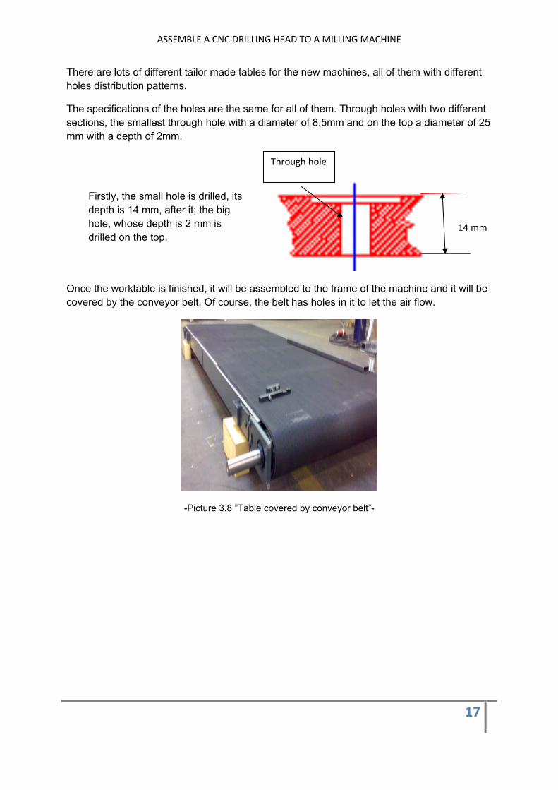
The specifications of the holes are the same for all of them. Through holes with two different sections, the smallest through hole with a diameter of 8.5mm and on the top a diameter of 25 mm with a depth of 2mm.
Once the worktable is finished, it will be assembled to the frame of the machine and it will be covered by the conveyor belt. Of course, the belt has holes in it to let the air flow.
-Picture 3.8 ”Table covered by conveyor belt”-
Firstly, the small hole is drilled, its depth is 14 mm, after it; the big hole, whose depth is 2 mm is drilled on the top.
Through hole
14 mm
ASSEMBLE A CNC DRILLING HEAD TO A MILLING MACHINE
18
4 ASSEMBLING DRILLING HEAD TO MILLING MACHINE
As it has been explained on section 3.1, the milling machine consists of three heads. The third one, which is on the left side of the bridge, is going to be taken off. It will be replaced by the new drilling head.
Picture 4.1”Position where the new drilling head will be assembled”
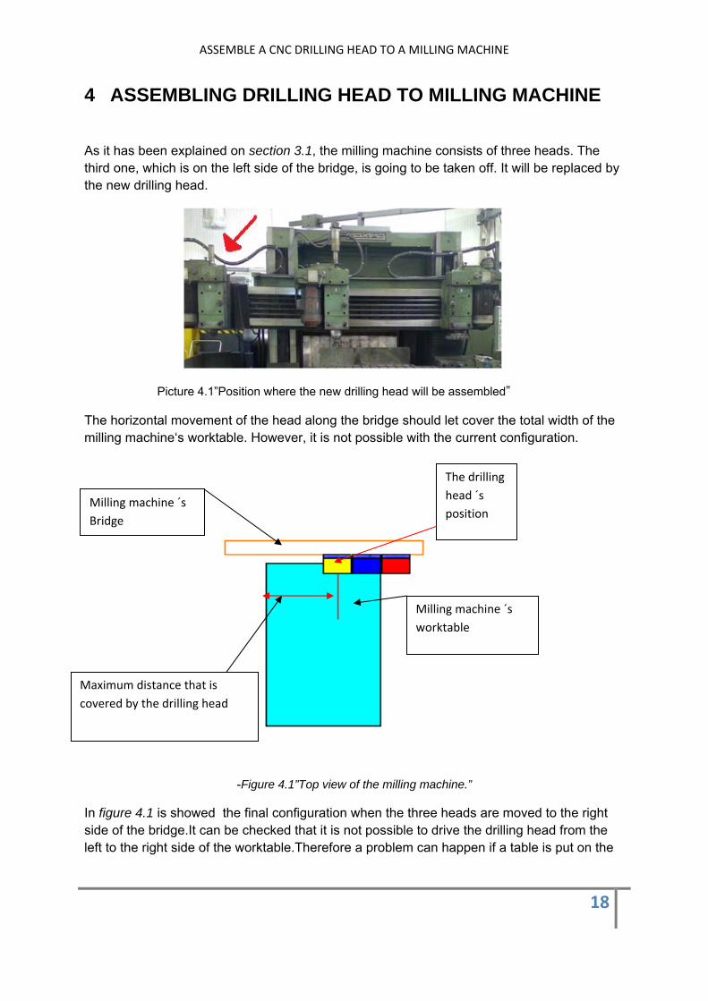
The horizontal movement of the head along the bridge should let cover the total width of the milling machine‘s worktable. However, it is not possible with the current configuration.
-Figure 4.1”Top view of the milling machine.”
In figure 4.1 is showed the final configuration when the three heads are moved to the right side of the bridge.It can be checked that it is not possible to drive the drilling head from the left to the right side of the worktable.Therefore a problem can happen if a table is put on the
Milling machine ´s Bridge
Maximum distance that is covered by the drilling head
Milling machine ´s worktable
The drilling head ´s position
ASSEMBLE A CNC DRILLING HEAD TO A MILLING MACHINE
19
right side of the milling machine ´s worktable.The problem is that the drilling tool can´t achieve the position.
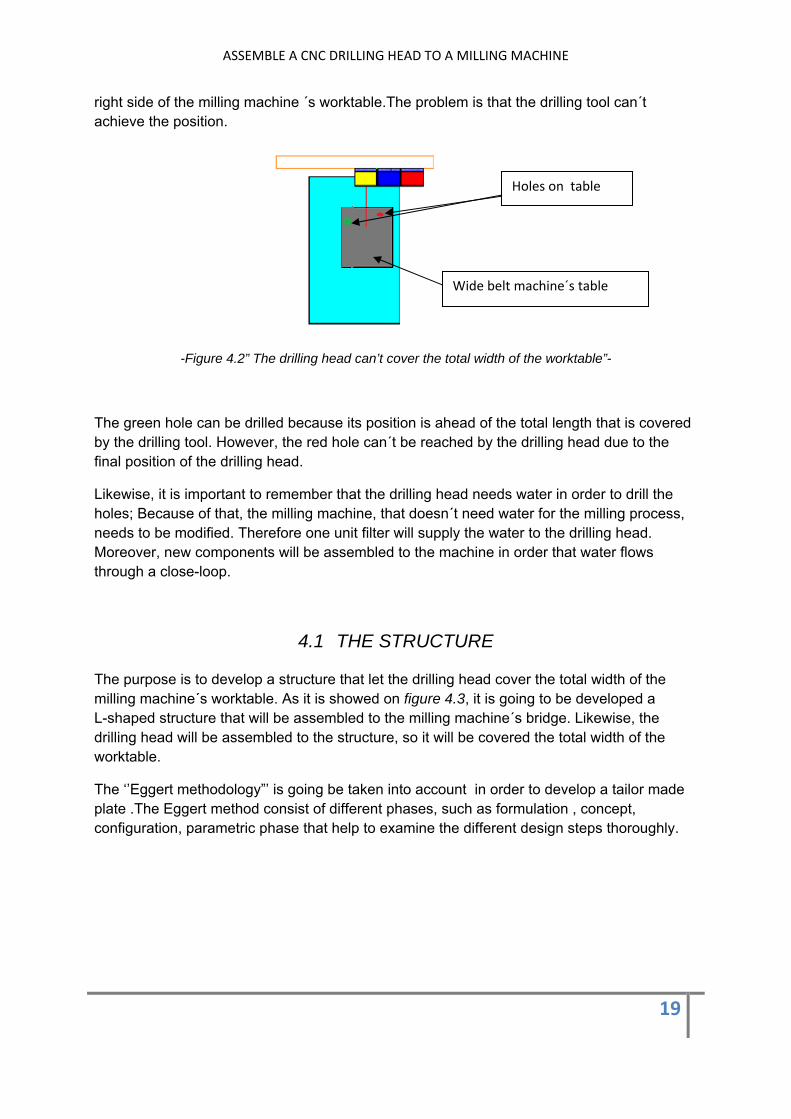
-Figure 4.2” The drilling head can’t cover the total width of the worktable”-
The green hole can be drilled because its position is ahead of the total length that is covered by the drilling tool. However, the red hole can´t be reached by the drilling head due to the final position of the drilling head.
Likewise, it is important to remember that the drilling head needs water in order to drill the holes; Because of that, the milling machine, that doesn´t need water for the milling process, needs to be modified. Therefore one unit filter will supply the water to the drilling head. Moreover, new components will be assembled to the machine in order that water flows through a close-loop.
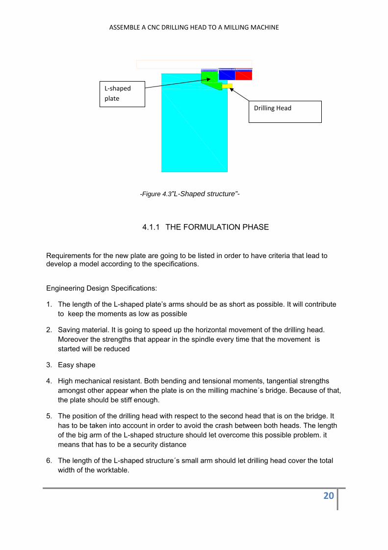
4.1 THE STRUCTURE The purpose is to develop a structure that let the drilling head cover the total width of the milling machine´s worktable. As it is showed on figure 4.3, it is going to be developed a L-shaped structure that will be assembled to the milling machine´s bridge. Likewise, the drilling head will be assembled to the structure, so it will be covered the total width of the worktable.
The ‘’Eggert methodology”’ is going be taken into account in order to develop a tailor made plate .The Eggert method consist of different phases, such as formulation , concept, configuration, parametric phase that help to examine the different design steps thoroughly.
Holes on table
Wide belt machine´s table
ASSEMBLE A CNC DRILLING HEAD TO A MILLING MACHINE
20
-Figure 4.3”L-Shaped structure”-
4.1.1 THE FORMULATION PHASE
Requirements for the new plate are going to be listed in order to have criteria that lead to develop a model according to the specifications.
Engineering Design Specifications:
1. The length of the L-shaped plate’s arms should be as short as possible. It will contribute to keep the moments as low as possible
2. Saving material. It is going to speed up the horizontal movement of the drilling head. Moreover the strengths that appear in the spindle every time that the movement is started will be reduced
3. Easy shape
4. High mechanical resistant. Both bending and tensional moments, tangential strengths amongst other appear when the plate is on the milling machine´s bridge. Because of that, the plate should be stiff enough.
5. The position of the drilling head with respect to the second head that is on the bridge. It has to be taken into account in order to avoid the crash between both heads. The length of the big arm of the L-shaped structure should let overcome this possible problem. it means that has to be a security distance
6. The length of the L-shaped structure´s small arm should let drilling head cover the total width of the worktable.
L‐shaped plate
Drilling Head

ASSEMBLE A CNC DRILLING HEAD TO A MILLING MACHINE
21
7. The position of the drilling head with respect to the plate. As higher the assembling is done, the more distance the drilling tool has to travel
8. Avoid sharp points
9. Let transition between sections of different dimensions
10. Symmetrical shaped
11. The kind of process to manufacture the plate. Bending process is better that too much welding process
12. Dimensions have to be measured in a proper way. Correct dimension to let coupling plate-bridge, Coupling plate-drilling head
13. Distance from the bit to the metal sheet where holes has to be done, as short as possible in order to save time
14. Cost of fabrication
15. Delivery time
-Figure 4.4 “New configuration on the milling machine ”
In figure 4.4 is showed how the L-shaped structure let achieve the right side of the milling machine ´s worktable.In the new configuration, the drilling head´s final position is in front of the second head.Because of that,it is important to establish a security distance from the bridge to the starting of the short arm of the structure.In order words , the crash between both heads has to be avoided.
Plate
Security distance
Milling head 1 Milling head 2
Position that was achieved with the original configuration

ASSEMBLE A CNC DRILLING HEAD TO A MILLING MACHINE
22
4.1.2 THE CONCEPT PHASE
Once the requirements have been established, a brainstorming of the possible structures that could carry out the goal is developed. The three best concepts are detailed below.
The first model is an L-shaped steel structure. It is composed of steel beams welded together.
-Figure 4.5”First model-”
The structure has a constant rectangular section .It is sized in relation with the bridge’s plate. Moreover, in figure 4.5, can be identified both the security distance (red arrow) and the length of the small arm (green arrow). It and the length of the drilling head let achieve the total width of the milling machine’s worktable
The Second model is a L-shaped structure. It is a hollow construction with two different sections.
-Figure 4.6”Second model”-
Side of the structure that will be assembled to the milling machine´s bridge
Side where the drilling head will be assembled
Both sides will be closed by means of two thin plates.
Height 2
Height 1
Beams

ASSEMBLE A CNC DRILLING HEAD TO A MILLING MACHINE
23
The length of the first section let make sure that the drilling head won’t crash with the second head when are in front of each other. Moreover, the construction has two heights. In order to make the transition, the top face of the first section has an inclination. The security distance establishes the point where the first section finishes and the second section starts. The structure is closed on the sides where the assembling with both the bridge’s plate and the drilling head is done. Finally, the height of the short arm is sized in order to let vary the level where the drilling head will be assembled.
The third model is an L-shaped structure with rectangular-shaped hollow configuration.
-Figure 4.7”Third model”-
The long arm of the structure has a cone- shaped section. It let a symmetrical reduction from both upper and lower side of the structure. The height of the small arm is according to the dimensions of the back part of the drilling head. Both sides of the structure are close by means of two thin plates.
4.1.2.1 JUDGE THE FINAL CONCEPT
Once the final concepts have been explained, all of them have to be compared by means of a weighted method in order to find the concept that let achieve the requirements in a best way. The three final concepts are comparing according to the most important and variables requirements .The requirements are weight rated, it is established that the final sum is one hundred percent. Every model is evaluated in order to established the model that tailor in a best way to the requirement .This rated method goes from 9 , the best affinity, to three , it means , the model that worst suits with the specification. If the rated weight of each requirement is multiplicity by the scale (3, 6, 9) belong to each model, it is got the final score for each model. Below is showed a morphological matrix.
Symmetrical reduction
Cone‐shaped section

ASSEMBLE A CNC DRILLING HEAD TO A MILLING MACHINE
24
Criteria Weight Model 1
Model 2
Model 3
Saving material 25% 6 1.5 9 2.25 9 2.25
Geometry 10 % 9 0.9 9 0.9 9 0.9
Mechanical Resistant 15% 9 1.35 9 1.35 6 0.9
Relative height drilling head 15% 9 1.35 9 1.35 6 0.9
Extension L -arm 20% 6 1.2 6 1.2 6 1.2
Manufacture process 15% 3 0.45 9 1.35 6 0.9
100%
-Chart 4.1. ”Morphological matrix”-
Total score 6.75 8.4 7.05
-20% 0% -17%
ASSEMBLE A CNC DRILLING HEAD TO A MILLING MACHINE
25
4.1.2.2 CONCLUSIONS
According to the requirements that have been showed in the morphological matrix, the three concepts are analyzed. The most important is to develop a light structure. The motor drives the spindle that leads the drilling head from the right to the left side of the bridge and vice versa. When the horizontal movement of the head either start or stops, forces appear in the spindle. The lighter the construction is, the lower the forces are. The forces erode the spindle, because of that, the play in the spindle get higher and it can be a problem to achieve the position when the program will be developed. In the same way, the purpose is to speed up the horizontal movement of the drilling head, so a heavy construction doesn´t contribute to achieve it. Therefore the hollow constructions (model 2, 3) suit better for this requirement. The length of the L-shaped structure ´s arms let overcome the two problems that has been explained at the beginning of the section 4.On the one hand, the need to cover the total width of the milling machine ´s worktable and on the other, the security distance to avoid the crash between heads. All the concepts have the same dimensions with respect to these lengths. In spite of it, a new problem appears. Both moments and forces are going to be increased on the construction. Because of that, the construction should be stiff enough. Being the model 3 the weak concept due to the lower resistant section. The drilling head is assembled on the plate that closed the short arm of the construction; its height with respect to the base of the bridge has a high importance. As higher the drilling head is, the more distance the drilling tool has to travel. It happens with model 3. Finally, the relation with the manufacture process, the main process in both model 2 and 3 is the bending process. In the model one, it is the welding process.
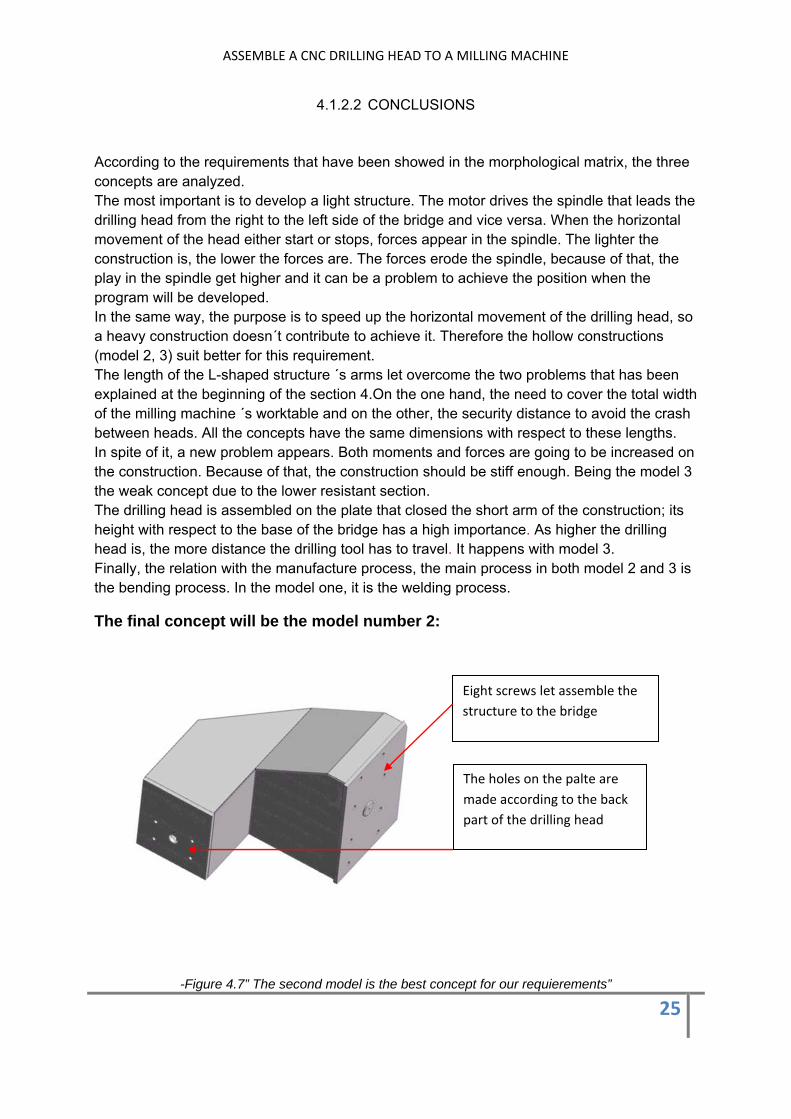
The final concept will be the model number 2:
-Figure 4.7” The second model is the best concept for our requierements”
Eight screws let assemble the structure to the bridge
The holes on the palte are made according to the back part of the drilling head

ASSEMBLE A CNC DRILLING HEAD TO A MILLING MACHINE
26
4.1.3 THE CONFIGURATION PHASE
In this phase, it is time to start to work specifically on the components and parts of the concept that has been chosen as the final solution. In order words, it is going to be analyzed possible variables that can influence in the concept’s behavior.
The height of the drilling head with respect the base of the plate is one of the variables that can be modified and let us to check what is the best one. For this reason it was decided to create two levels of heights. Depend on the position, it will possible to control the drilling tool -milling machine’s worktable distance. Likewise, in order to help to assemble the structure to the bridge holes at two levels will be make to put screws
-Figure 4.8”Improvements of the model”-
The stiffener plates that are put inside the structure make stiffer the construction
Likewise,the transition between sections will be possible by means of the inclination face on the upper side.
Therefore, the final global configuration is showed in the following drawing
Two possible levels to assemble the drilling head
Holes are made in order to help to put the screws
ASSEMBLE A CNC DRILLING HEAD TO A MILLING MACHINE
27
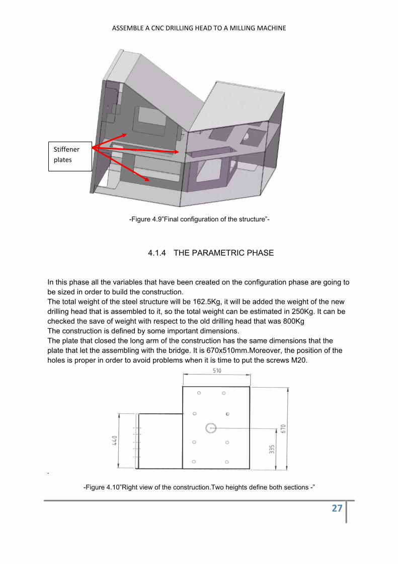
-Figure 4.9”Final configuration of the structure”-
4.1.4 THE PARAMETRIC PHASE
In this phase all the variables that have been created on the configuration phase are going to be sized in order to build the construction. The total weight of the steel structure will be 162.5Kg, it will be added the weight of the new drilling head that is assembled to it, so the total weight can be estimated in 250Kg. It can be checked the save of weight with respect to the old drilling head that was 800Kg The construction is defined by some important dimensions. The plate that closed the long arm of the construction has the same dimensions that the plate that let the assembling with the bridge. It is 670x510mm.Moreover, the position of the holes is proper in order to avoid problems when it is time to put the screws M20.
.
-Figure 4.10”Right view of the construction.Two heights define both sections -”
Stiffener plates

ASSEMBLE A CNC DRILLING HEAD TO A MILLING MACHINE
28
The plate that closed the short arm of the construction where it is going to be assembled the drilling head has a lower height due to the drilling head specifications; it is 390x440 mm. Likewise, there are two levels where assemble the drilling head
.
-Figure 4.10” Front view of the construction”
The security distance that avoids the crash between the drilling head and the second head is 500mm.Then, the small arm of the L-Shaped construction starts. The length of the small arm that is needed in order to achieve the total width of the milling machine’s worktable is 365mm that together with the length of the drilling head will let cover it.
-Figure 4.11 “Top view of the construction”
ASSEMBLE A CNC DRILLING HEAD TO A MILLING MACHINE
29
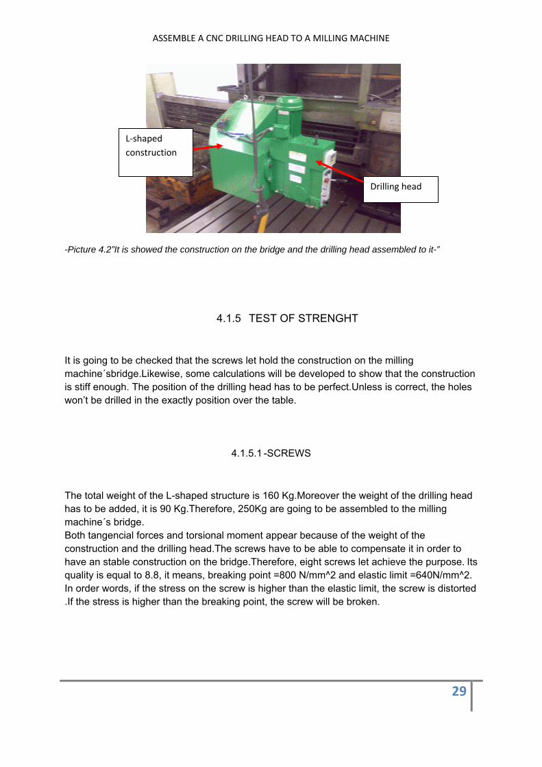
-Picture 4.2”It is showed the construction on the bridge and the drilling head assembled to it-”
4.1.5 TEST OF STRENGHT
It is going to be checked that the screws let hold the construction on the milling machine´sbridge.Likewise, some calculations will be developed to show that the construction is stiff enough. The position of the drilling head has to be perfect.Unless is correct, the holes won’t be drilled in the exactly position over the table.
4.1.5.1 -SCREWS
The total weight of the L-shaped structure is 160 Kg.Moreover the weight of the drilling head has to be added, it is 90 Kg.Therefore, 250Kg are going to be assembled to the milling machine´s bridge. Both tangencial forces and torsional moment appear because of the weight of the construction and the drilling head.The screws have to be able to compensate it in order to have an stable construction on the bridge.Therefore, eight screws let achieve the purpose. Its quality is equal to 8.8, it means, breaking point =800 N/mm^2 and elastic limit =640N/mm^2. In order words, if the stress on the screw is higher than the elastic limit, the screw is distorted .If the stress is higher than the breaking point, the screw will be broken.
L‐shaped construction
Drilling head
ASSEMBLE A CNC DRILLING HEAD TO A MILLING MACHINE
30
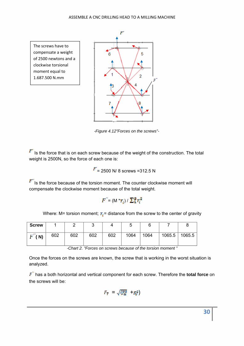
-Figure 4.12”Forces on the screws”-
Is the force that is on each screw because of the weight of the construction. The total weight is 2500N, so the force of each one is:
= 2500 N/ 8 screws =312.5 N
Is the force because of the torsion moment. The counter clockwise moment will compensate the clockwise moment because of the total weight.
= (M * ) /
Where: M= torsion moment; = distance from the screw to the center of gravity
Screw 1 2 3 4 5 6 7 8
( N) 602 602 602 602 1064 1064 1065.5 1065.5
-Chart 2. ”Forces on screws because of the torsion moment ”
Once the forces on the screws are known, the screw that is working in the worst situation is analyzed.
has a both horizontal and vertical component for each screw. Therefore the total force on the screws will be:
= + )
The screws have to compensate a weight of 2500 newtons and a clockwise torsional moment equal to 1.687.500 N.mm

ASSEMBLE A CNC DRILLING HEAD TO A MILLING MACHINE
31
Screw 1 2 3 4 5 6 7 8
( N) 860 860 860 860 1200 1200 1227 1227
-Chart 3. ”Total forces on screws”
The screws 7 and 8 have the highest forces. The maximum tangential stress on the screws is equal to:
Tangential stress = (Eq.1)
In order to make sure that the screw can’t be broken, it is going to be established a security coefficient equal to 2.
Security Coefficient = (Eq.2)
From equation 2, the maximum tangential stress is
Tangential stress = = 160 N/mm^2
If tangential stress is put in equation 1, the maximum force that can be on the screw is:
Force= tangential stress *number plans* resistant area of the screw Maximum force = 160 N/mm^2 *2* 314.4 mm^2 = 100,500N
If it is compared the higher force that there is on the worst screw, it can be checked that is eighty times lower than the maximum force.
The complete calculation can be found on Appendix
4.1.5.2-STRENGHT OF THE STRUCTURE
In order to know if the structure is stiff enough, it is going to be analyzed the vertical displacement of the construction by means of the virtual work theorem.

ASSEMBLE A CNC DRILLING HEAD TO A MILLING MACHINE
32
-Figure 4.13” Sketch of the construction”-
In figure 4.13 is showed a sketch of the L-shaped construction. Moreover, all the forces are showed. Both Q1 and Q2 are the own weight of the structure.
Q1=0.48N/mm, Q2=0.73N/mm
P1 is the sum of the weight of the plate that close the short arm of the construction and the drilling head. P1=1450N P2 is the weight of the plate that close the long arm of the construction. All of these forces are downwards forces except R (on section B) that is an upward force in order to keep the equilibrium of the structure. Likewise, a counterclockwise torsion moment appears in section B with the same purpose. It was analyzed in the previous section.
The virtual work theorem is based on virtual system of forces. It let analyzed both translational and rotational movements on structures. Therefore, if the vertical displacement of section A has to be known, a virtual system of forces has to be established.
A virtual force, whose numerical value is one, is put on section A. This section is where the drilling head is assembled to the construction. As can be checked, it is needed a force on section B in order to keep the equilibrium. In the same way, a counterclockwise torsion moment will appear is section B.
L1
Plate in contact with the bridge (Section B)

ASSEMBLE A CNC DRILLING HEAD TO A MILLING MACHINE
33
-Figure 4.14” virtual system”-
Both systems involves the development of tangential force diagrams and bending moment diagrams . The tangential forces can be neglected in order to calculate the displacement of section A.The reason is that the magnitude of the bending moments is higher.According to the virtual work theorem, the vertical displacement on section A is calculated below.
= * )/ E* ) dx
Where:
: Bending moments on virtual system
: Bending moment real system [N.mm]
: Inertia [mm^4]
E: Steel young´s module [N/mm^2]
If it is integrated along the total length of the L-shaped construction
= =
= 0.018mm
The conclusion is that the construction is stiff enough.
The complete calculation can be checked in Appendix
1
1Section A
L2
Section B

ASSEMBLE A CNC DRILLING HEAD TO A MILLING MACHINE
34
5 THE FILTER UNIT
The drilling head is going to need water in order to make sure the proper operation of the drilling process. Because of that, the milling machine has to be rebuilt. The modifications will let create a close-loop. In other words, the pumped water to the drilling head will flow through the milling machine’s canals to the filter unit, and so on. In order that the water flows throught the canals to the front part of the milling machine’s worktable, the back part has to be closed.Because of that, the water can only flow in one direction. The canals that are in the middle of the worktable come out into a container (black circle in picture).The water that flows throught the canals that are in the both left and right side has to be driven to the unit filter. In order to achive it, two pockets will be assembled to both sides of the worktable (green line in picture). Therefore, the right pocket lead the water to the container and it flows until the left pocket. Two tunnels will be assembled on the left side of the milling machine.Its position will be specifically below the canals located on the right side of the worktable.Moreover ,the total length of the tunnel s will cover the total displacement of the worktable. Both tunnels come out into the filter unit.
Picture 5.1”Close loop on milling machine”
A. Back part of the milling machine’s worktable has to be closed
B. Two tunnels will let the flow of water into the filter
Water flows through canals to the front part of the worktable
Container
C. Two pockets will let lead the flow of water until the filter unit
ASSEMBLE A CNC DRILLING HEAD TO A MILLING MACHINE
35
5.1 THE POCKETS
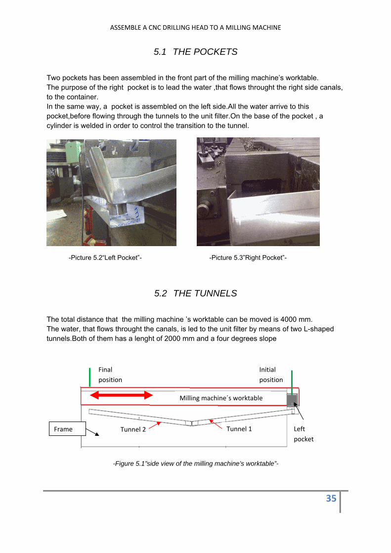
Two pockets has been assembled in the front part of the milling machine’s worktable. The purpose of the right pocket is to lead the water ,that flows throught the right side canals, to the container. In the same way, a pocket is assembled on the left side.All the water arrive to this pocket,before flowing through the tunnels to the unit filter.On the base of the pocket , a cylinder is welded in order to control the transition to the tunnel.
-Picture 5.2“Left Pocket”- -Picture 5.3”Right Pocket”-
5.2 THE TUNNELS
The total distance that the milling machine ’s worktable can be moved is 4000 mm. The water, that flows throught the canals, is led to the unit filter by means of two L-shaped tunnels.Both of them has a lenght of 2000 mm and a four degrees slope
-Figure 5.1”side view of the milling machine’s worktable”-
Tunnel 1 Tunnel 2 Left pocket
Milling machine´s worktable
Frame
Initial position
Final position

ASSEMBLE A CNC DRILLING HEAD TO A MILLING MACHINE
36
The tunnels are asembled to the milling machine´s frame.The worktable moves from the initial position to the final position,the left pocket as well.The water flows through the pocket to the either tunnel 1 or 2.It depends on the position of the worktable.
-Figure 5.2”Overview of the system”-
The L-shaped tunnels let achieve the position where the unit filter will be put.
5.3 SPECIAL PARTS
The back part of the milling machine’s worktable has to be closed. It makes sure that the water flows throught the front part.Therefore,some stainless steel sheets are assembled by means of screws
Work table
Left pocket
Tunnels
Right pocket
ASSEMBLE A CNC DRILLING HEAD TO A MILLING MACHINE
37
6 THE ELECTRICAL AND ELECTRONIC REBUILT The drilling process is going to be automated.In means that a program will be developed in order to control the process. The program will consist of a sequential list of instructions.It will be carried out in order to achieve the goal. Nowadays,the milling machine has its own electrical cabinet.However,the automated drilling process involves the need to incorporate both new electrical and electronic devices. Therefore, an external new cabinet will control the drilling process. After this rebuilt on the milling machine, it will be possible to work on either milling or drilling mode.
6.1 THE PROGRAMMABLE LOGIC CONTROLLER (PLC)
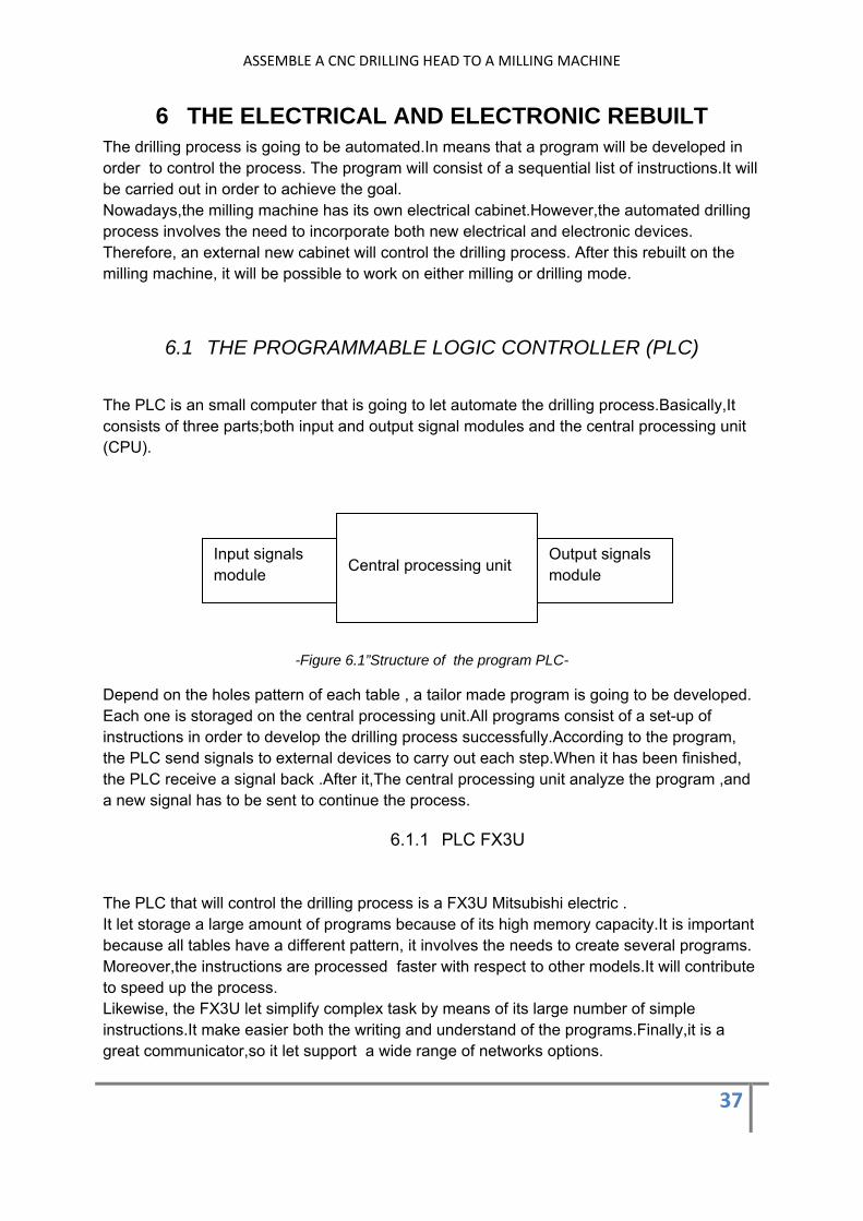
The PLC is an small computer that is going to let automate the drilling process.Basically,It consists of three parts;both input and output signal modules and the central processing unit (CPU).
-Figure 6.1”Structure of the program PLC-
Depend on the holes pattern of each table , a tailor made program is going to be developed. Each one is storaged on the central processing unit.All programs consist of a set-up of instructions in order to develop the drilling process successfully.According to the program, the PLC send signals to external devices to carry out each step.When it has been finished, the PLC receive a signal back .After it,The central processing unit analyze the program ,and a new signal has to be sent to continue the process.
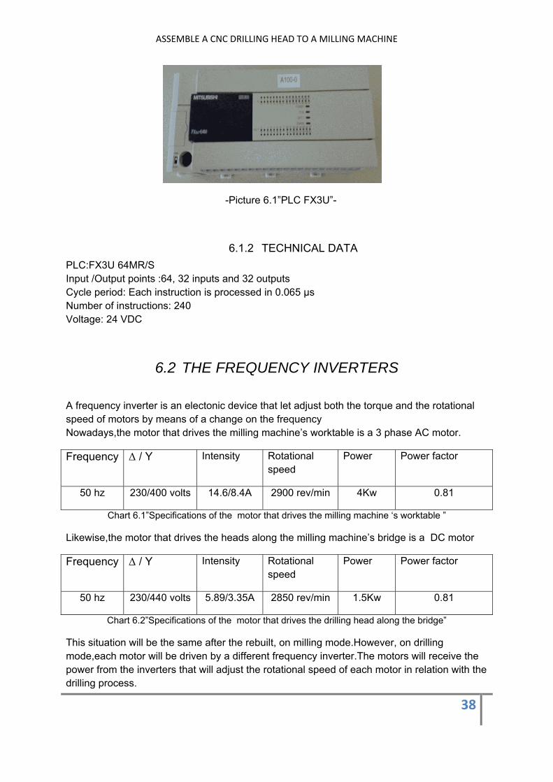
6.1.1 PLC FX3U
The PLC that will control the drilling process is a FX3U Mitsubishi electric . It let storage a large amount of programs because of its high memory capacity.It is important because all tables have a different pattern, it involves the needs to create several programs. Moreover,the instructions are processed faster with respect to other models.It will contribute to speed up the process. Likewise, the FX3U let simplify complex task by means of its large number of simple instructions.It make easier both the writing and understand of the programs.Finally,it is a great communicator,so it let support a wide range of networks options.
Central processing unit Output signals module
Input signals module
ASSEMBLE A CNC DRILLING HEAD TO A MILLING MACHINE
38
-Picture 6.1”PLC FX3U”-
6.1.2 TECHNICAL DATA PLC:FX3U 64MR/S Input /Output points :64, 32 inputs and 32 outputs Cycle period: Each instruction is processed in 0.065 μs Number of instructions: 240 Voltage: 24 VDC
6.2 THE FREQUENCY INVERTERS
A frequency inverter is an electonic device that let adjust both the torque and the rotational speed of motors by means of a change on the frequency Nowadays,the motor that drives the milling machine’s worktable is a 3 phase AC motor.
Frequency Δ / Y Intensity Rotational speed
Power Power factor
50 hz 230/400 volts 14.6/8.4A 2900 rev/min 4Kw 0.81
Chart 6.1”Specifications of the motor that drives the milling machine ‘s worktable ”
Likewise,the motor that drives the heads along the milling machine’s bridge is a DC motor
Frequency Δ / Y Intensity Rotational speed
Power Power factor
50 hz 230/440 volts 5.89/3.35A 2850 rev/min 1.5Kw 0.81
Chart 6.2”Specifications of the motor that drives the drilling head along the bridge”
This situation will be the same after the rebuilt, on milling mode.However, on drilling mode,each motor will be driven by a different frequency inverter.The motors will receive the power from the inverters that will adjust the rotational speed of each motor in relation with the drilling process.

ASSEMBLE A CNC DRILLING HEAD TO A MILLING MACHINE
39
In order to go from one hole to other, it is necessary to move both the drilling head and the milling machine ‘s worktable.It involves that the motors has to run as fast as possible until the drilling tool is close to the hole.Then, the speed has to be reduced to reach the exactly position of the hole.
6.2.1 FREQUENCY INVERTERS FRA-700
Each motor will be controlled by a frequency inverter FRA-700 from Mitsubishi electric. The FRA-700 is design for four overload ranges, it means that it is possible to get a higher current than the rated current for a short period of time. Moreover,both the PLC and the frequency inverter belong to the same branch , it help to improve the communication . Likewise, a programmable logic controller is integrated on the frequency inverter. It let set parameters on the frequency inverter to carry out useful tasks.
-Picture 6.2”Frequency inverter”-
6.2.2 TECHNICAL DATA OF FREQUENCY INVERTERS
Frequency inverter FRA-A740-00052 and Frequency Inverter FRA-A740-000126 : Three phase, 400V
Frequency inverter
Rated current (A)
Rated motor capacity (Kw)
Frequency inverter
Rated current (A)
Rated motor capacity (Kw)
00052 4 1.5 000126 9 4
Chart 6.3”Specifications of the frequency inverters”

ASSEMBLE A CNC DRILLING HEAD TO A MILLING MACHINE
40
6.3 ENCODER
An encoder is a device that is assembled to the motor´s shaft. It counts the number of rotations of the motor.Two encoders will be used for this purpose.One of them will be on the the motor that drives the milling machine´s worktable. The second one will be on the motor that drives the heads along the bridge. Depending on the rotations , either the milling machine ´s worktable or drilling head move a distance.In order words, each revolution of the motor involves a linear displacement.
-Picture 6.3”Encoder”-
Both the shaft motor and the encoder´s shaft rotate at the same speed.Two square waves that out of phase 90º degrees are output signals from the encoder.These signals give information about the rotations of the motor ´s shaft and the sense direction
-Figure 6.2”Pulse waves ”-
If signal A is ahead of B , it means that shaft rotate clockwise.On the other hand , if B is ahead A ,the shaft rotate counter clockwise. As much as pulses are generated, the more accuracy the information is. The encoder is connected to the frequency convertor, so the signals are received by it.Therefore,some parameters has to be set on the frequency inverter to make sure that the displacements of both the worktable and the drilling head are correct. This process is controlled by the programmable logic controller that is integrated on the frequency inverter.
Encoder´s shaft
Encoder
Pulse

ASSEMBLE A CNC DRILLING HEAD TO A MILLING MACHINE
41
6.4 NEW CABINET FOR DRILLING MODE
The PLC and the frequency inverters will be inside the cabinet.Moreover,in the main panel of the cabinet a screen, a joystick, an emergency button, a switch button and a reset button will be put.
6.4.1 THE SCREEN It is going to be connected to the PLC.By means of the screen, it will possible to gain access to the storaged information on the CPU.It means information about the instructions that define each drilling process program.The screen will let control the drilling process.In order words, all the steps will be visualized on the screen.
6.4.2THE JOYSTICK Before starting the drilling process, it is neccesary to establish an starting point.In order to reach it , a joystick is going to be chosen for this function.The joystick let the movement in four directions.The backward and forward movement will let the movement of the milling machine´s worktable.Likewise, the right an left movement will involve the displacement of the drilling head along the milling machine´s bridge.

ASSEMBLE A CNC DRILLING HEAD TO A MILLING MACHINE
42
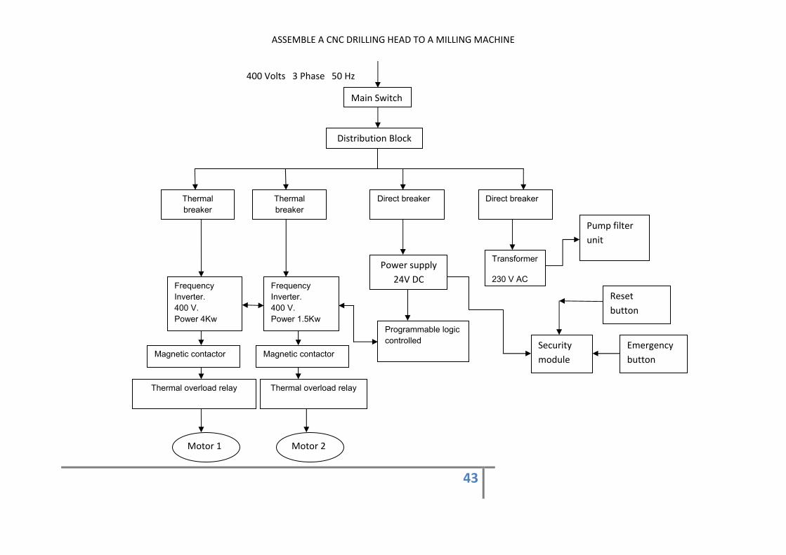
6.5 THE BLOCK DIAGRAMS Once the main both electrical and electronic components has been explained, it is time to connect all the devices.
-Picture 6.4” overview components on cabinet”-
The main switch let supply energy to the electrical cabinet.Then, the distribution block lead it to the different components.It is received by the two frequency inverters, the transformer 1 and the trasnsformer 2. The power from the frequency inverters is used to drive the motors.The motor that drives the drilling head along the bridge and the motor that drives the milling machine ´s worktable. The tranformer 1 changes the voltage from 400 Volts to 230 Volts, and it is supply to the unit filter. The transformer 2 changes the voltage from 400 Volts to 24 V DC.It is delivered to the PLC and to the security module. The security module let stop the machine in case of something is wrong .It is activated by means of the emergency button. In order to start the machine again , the reset button let it.
-Picture 6.5” Panel control ”
Security module
PLC
Distribution Block
Main switch
Thermal breakers
Transformer 1 Frequency convertors
Transformer 2
Reset button
ASSEMBLE A CNC DRILLING HEAD TO A MILLING MACHINE
43
400 Volts 3 Phase 50 Hz
Main Switch
Distribution Block
Thermal breaker
Thermal breaker
Direct breaker Direct breaker
Frequency Inverter. 400 V. Power 4Kw
Frequency Inverter. 400 V. Power 1.5Kw
Magnetic contactor
Thermal overload relay Thermal overload relay
Motor 1 Motor 2
Power supply 24V DC
Programmable logic controlled
Transformer
230 V AC
Reset button
Emergency button
Security module
Magnetic contactor
Pump filter unit
ASSEMBLE A CNC DRILLING HEAD TO A MILLING MACHINE
44
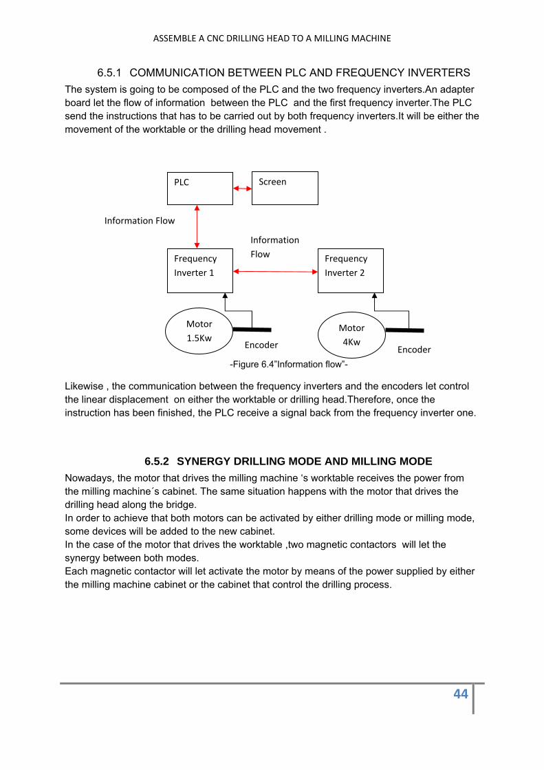
6.5.1 COMMUNICATION BETWEEN PLC AND FREQUENCY INVERTERS The system is going to be composed of the PLC and the two frequency inverters.An adapter board let the flow of information between the PLC and the first frequency inverter.The PLC send the instructions that has to be carried out by both frequency inverters.It will be either the movement of the worktable or the drilling head movement .
-Figure 6.4”Information flow”-
Likewise , the communication between the frequency inverters and the encoders let control the linear displacement on either the worktable or drilling head.Therefore, once the instruction has been finished, the PLC receive a signal back from the frequency inverter one.
6.5.2 SYNERGY DRILLING MODE AND MILLING MODE Nowadays, the motor that drives the milling machine ‘s worktable receives the power from the milling machine´s cabinet. The same situation happens with the motor that drives the drilling head along the bridge. In order to achieve that both motors can be activated by either drilling mode or milling mode, some devices will be added to the new cabinet. In the case of the motor that drives the worktable ,two magnetic contactors will let the synergy between both modes. Each magnetic contactor will let activate the motor by means of the power supplied by either the milling machine cabinet or the cabinet that control the drilling process.
PLC
Frequency Inverter 1
Screen
Frequency Inverter 2
Information Flow
Information Flow
Motor 1.5Kw
Motor 4Kw Encoder Encoder
ASSEMBLE A CNC DRILLING HEAD TO A MILLING MACHINE
45
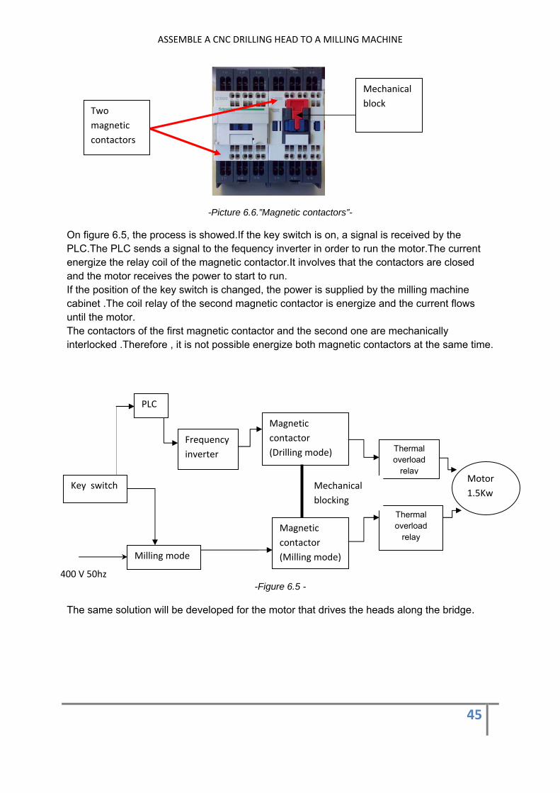
-Picture 6.6.”Magnetic contactors”-
On figure 6.5, the process is showed.If the key switch is on, a signal is received by the PLC.The PLC sends a signal to the fequency inverter in order to run the motor.The current energize the relay coil of the magnetic contactor.It involves that the contactors are closed and the motor receives the power to start to run. If the position of the key switch is changed, the power is supplied by the milling machine cabinet .The coil relay of the second magnetic contactor is energize and the current flows until the motor. The contactors of the first magnetic contactor and the second one are mechanically interlocked .Therefore , it is not possible energize both magnetic contactors at the same time.
-Figure 6.5 -
The same solution will be developed for the motor that drives the heads along the bridge.
Magnetic contactor (Drilling mode)
Key switch
Magnetic contactor (Milling mode)
Thermal overload
relay
Thermal overload
relay
Motor 1.5Kw
Milling mode
PLC
Frequency inverter
400 V 50hz
Mechanical blocking
Two magnetic contactors
Mechanical block

ASSEMBLE A CNC DRILLING HEAD TO A MILLING MACHINE
46
7 DEVELOPMENT OF THE STEPS OF THE DRILLING PROGRAM
The rows of holes, that are made over the tables, folows a specific pattern according to the table model.
-Figure7.1”Pattern of holes for one table”-
Each model has different specification in relation with the number of holes and its distances. One of the basic issues is the coordination between the drilling head movement and the worktable movement. It is going to be common for all the models. One option is to drill the holes along the Y axis. The basic idea about it will be to drill a hole and moving the worktable and so on until the end hole. Then the drilling head will be moved and the second row will be drilled as the first one. The second option will be to drill the holes along the X axis. A hole will be drilled and the drilling head will be moved until the following hole. It will be repeated until the end hole. Then the worktable will be moved to start the second row. The final decision about this issue is to choose the second way in order to develop the program. The reason is that the first option involves the need to move the worktable lots of times to drill the holes. In fact, it is equal to the number of holes. Of course, the second option involves the need to move the drilling head as many as times as number of holes the model has. However, the weight of the drilling head is sixty times lower than the worktable ´s estimated weight .It is 12000Kg.
Y axis
X axis
ASSEMBLE A CNC DRILLING HEAD TO A MILLING MACHINE
47
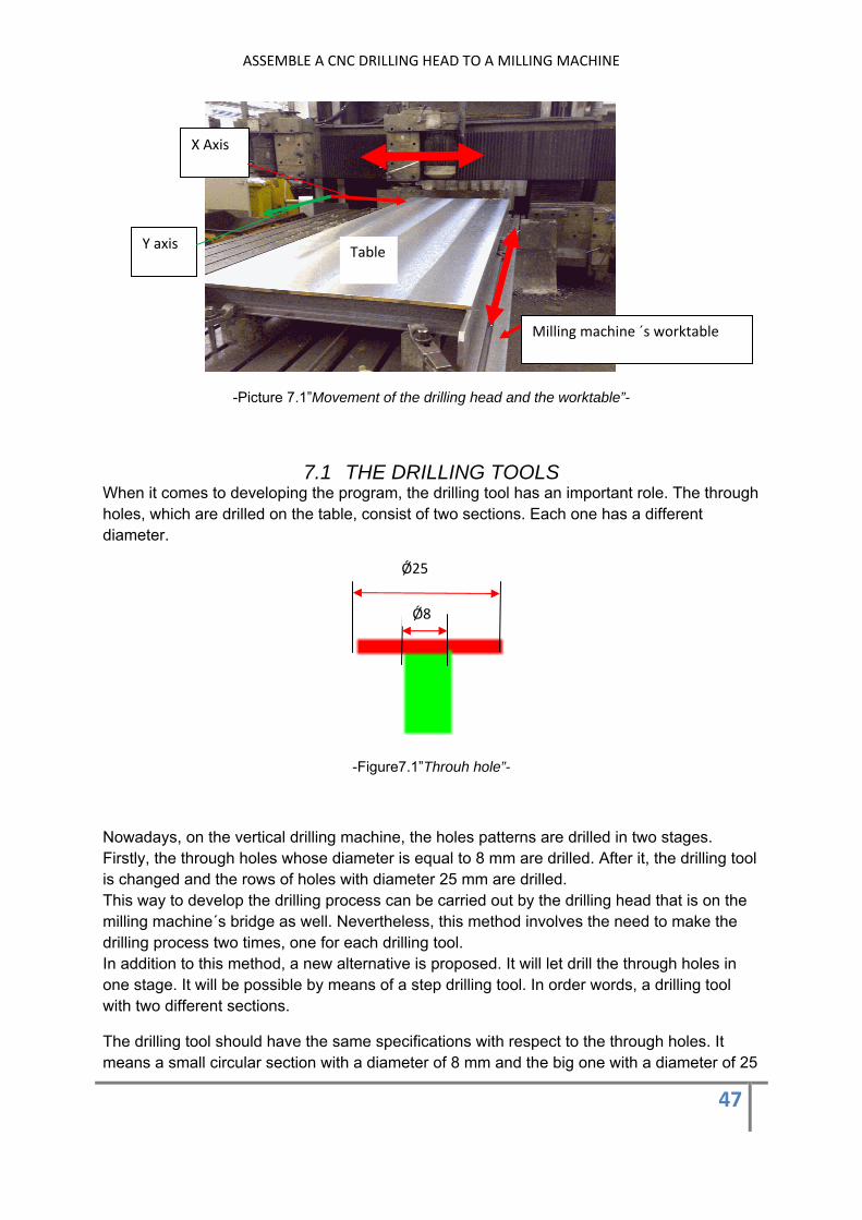
-Picture 7.1”Movement of the drilling head and the worktable”-
7.1 THE DRILLING TOOLS When it comes to developing the program, the drilling tool has an important role. The through holes, which are drilled on the table, consist of two sections. Each one has a different diameter.
-Figure7.1”Throuh hole”-
Nowadays, on the vertical drilling machine, the holes patterns are drilled in two stages. Firstly, the through holes whose diameter is equal to 8 mm are drilled. After it, the drilling tool is changed and the rows of holes with diameter 25 mm are drilled. This way to develop the drilling process can be carried out by the drilling head that is on the milling machine´s bridge as well. Nevertheless, this method involves the need to make the drilling process two times, one for each drilling tool. In addition to this method, a new alternative is proposed. It will let drill the through holes in one stage. It will be possible by means of a step drilling tool. In order words, a drilling tool with two different sections.
The drilling tool should have the same specifications with respect to the through holes. It means a small circular section with a diameter of 8 mm and the big one with a diameter of 25
X Axis
Y axis Table
Milling machine ´s worktable
Ǿ8
Ǿ25
ASSEMBLE A CNC DRILLING HEAD TO A MILLING MACHINE
48
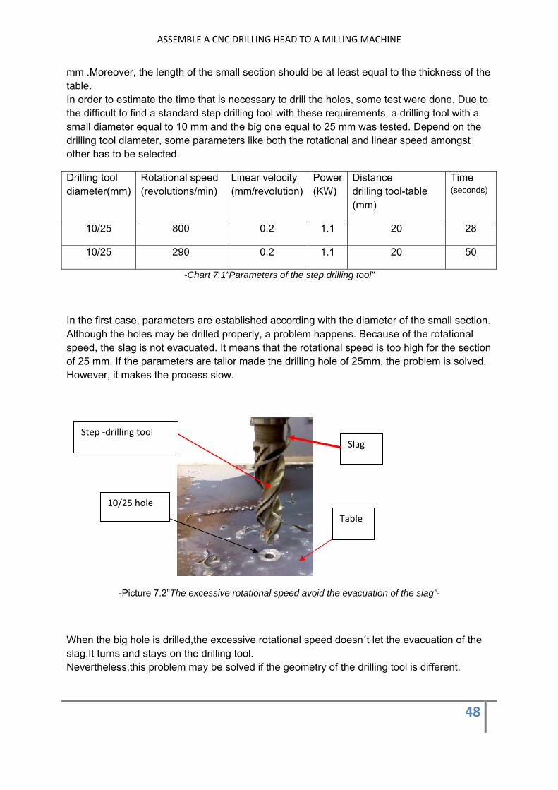
mm .Moreover, the length of the small section should be at least equal to the thickness of the table. In order to estimate the time that is necessary to drill the holes, some test were done. Due to the difficult to find a standard step drilling tool with these requirements, a drilling tool with a small diameter equal to 10 mm and the big one equal to 25 mm was tested. Depend on the drilling tool diameter, some parameters like both the rotational and linear speed amongst other has to be selected.
Drilling tool diameter(mm)
Rotational speed (revolutions/min)
Linear velocity (mm/revolution)
Power (KW)
Distance drilling tool-table (mm)
Time (seconds)
10/25 800 0.2 1.1 20 28
10/25 290 0.2 1.1 20 50
-Chart 7.1”Parameters of the step drilling tool”
In the first case, parameters are established according with the diameter of the small section. Although the holes may be drilled properly, a problem happens. Because of the rotational speed, the slag is not evacuated. It means that the rotational speed is too high for the section of 25 mm. If the parameters are tailor made the drilling hole of 25mm, the problem is solved. However, it makes the process slow.
-Picture 7.2”The excessive rotational speed avoid the evacuation of the slag”-
When the big hole is drilled,the excessive rotational speed doesn´t let the evacuation of the slag.It turns and stays on the drilling tool. Nevertheless,this problem may be solved if the geometry of the drilling tool is different.
Slag Step ‐drilling tool
Table
10/25 hole
ASSEMBLE A CNC DRILLING HEAD TO A MILLING MACHINE
49
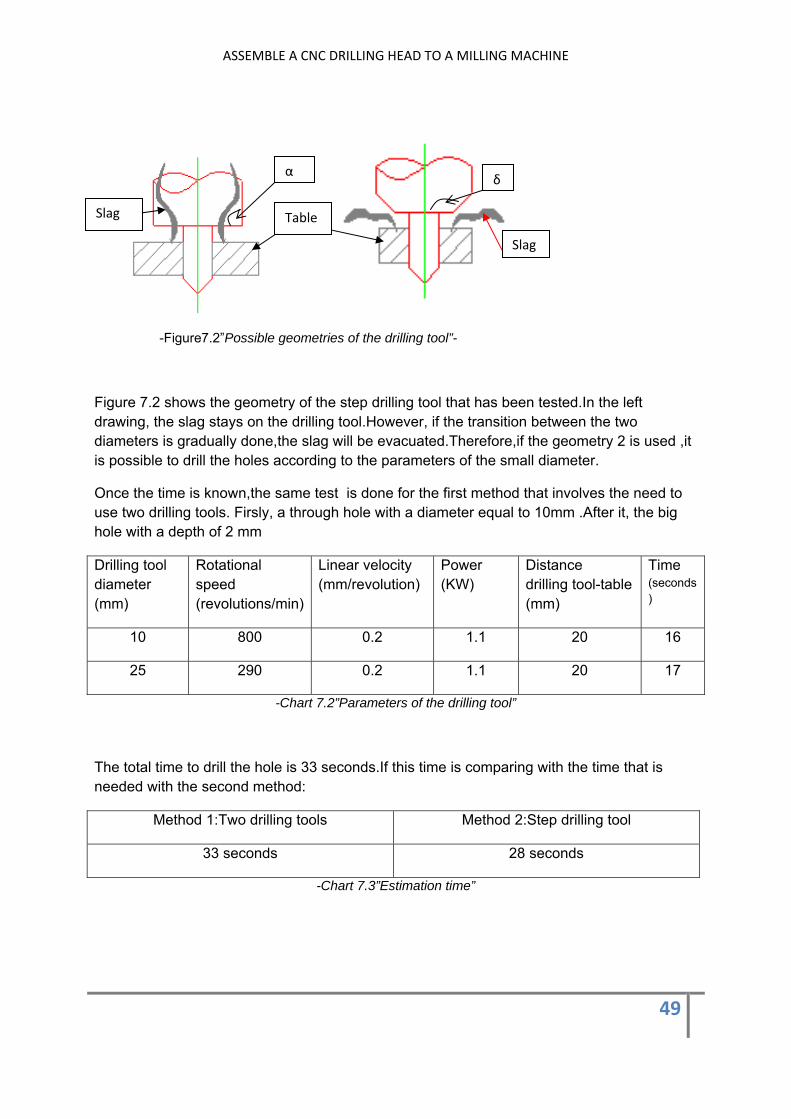
-Figure7.2”Possible geometries of the drilling tool”-
Figure 7.2 shows the geometry of the step drilling tool that has been tested.In the left drawing, the slag stays on the drilling tool.However, if the transition between the two diameters is gradually done,the slag will be evacuated.Therefore,if the geometry 2 is used ,it is possible to drill the holes according to the parameters of the small diameter.
Once the time is known,the same test is done for the first method that involves the need to use two drilling tools. Firsly, a through hole with a diameter equal to 10mm .After it, the big hole with a depth of 2 mm
Drilling tool diameter (mm)
Rotational speed (revolutions/min)
Linear velocity (mm/revolution)
Power (KW)
Distance drilling tool-table (mm)
Time (seconds)
10 800 0.2 1.1 20 16
25 290 0.2 1.1 20 17
-Chart 7.2”Parameters of the drilling tool”
The total time to drill the hole is 33 seconds.If this time is comparing with the time that is needed with the second method:
Method 1:Two drilling tools Method 2:Step drilling tool
33 seconds 28 seconds
-Chart 7.3”Estimation time”
α δ
Table
Slag
Slag

ASSEMBLE A CNC DRILLING HEAD TO A MILLING MACHINE
50
The step drilling let save 5 seconds.Moreover, it is important to remenber that the small diameter of the through hole that is drilled on the table is equal to 8 mm.It means that the rotational speed for this diameter is 1200 rev/second, so the time will be reduced.
7.2 THE AUTOMATIC FEED OF THE DRILLING HEAD
In the front part of the drilling head a scale let set the linear displacement of the drilling tool. This distance is established according to both the thickness of the table and the relative height of the drilling tool with respect to the table.
-Picture 7.3 “Regulation of the drilling tool positionl”
A spindle drives automatically the drilling tool up/down. Two limit switches let control the position of the drilling tool,
Two Limit switches
Spindle
Up / Down
ASSEMBLE A CNC DRILLING HEAD TO A MILLING MACHINE
51
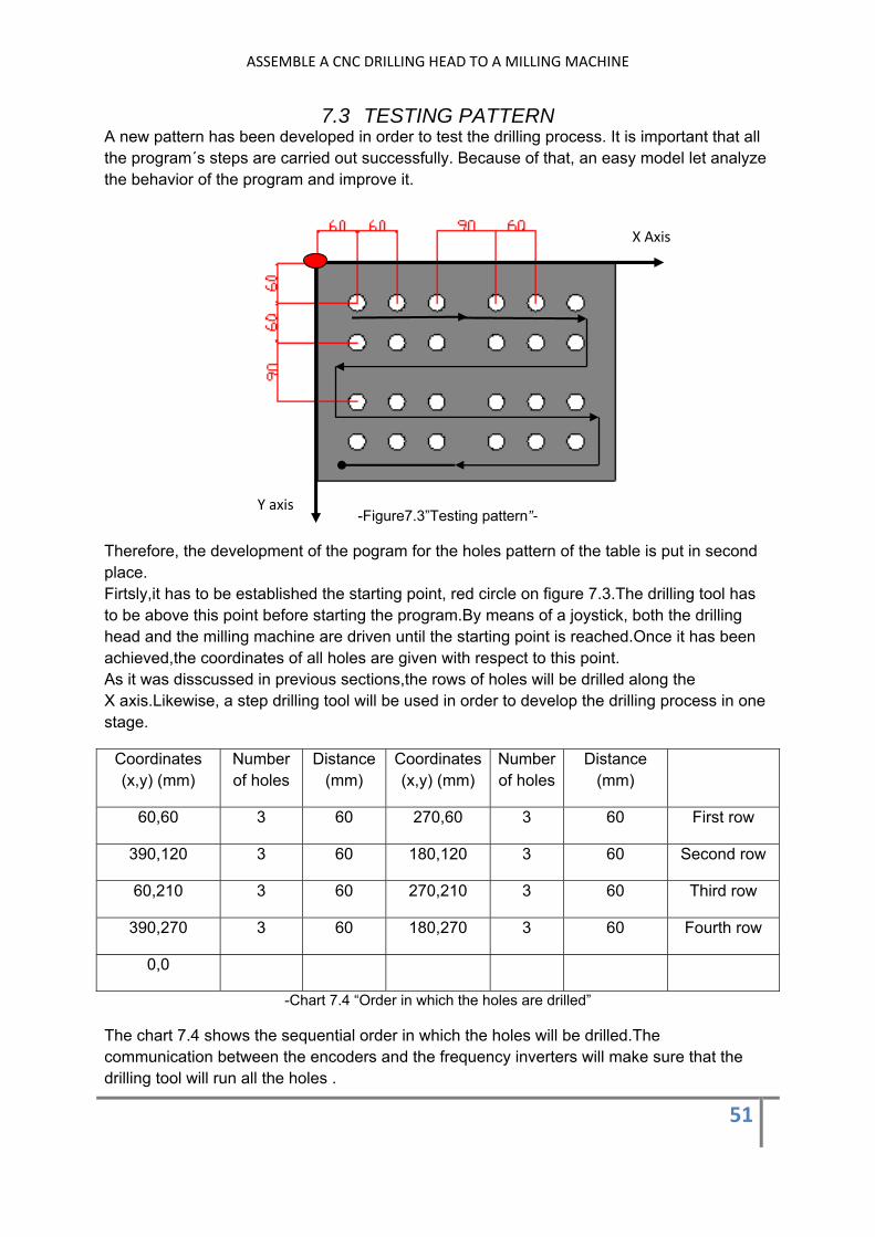
7.3 TESTING PATTERN A new pattern has been developed in order to test the drilling process. It is important that all the program´s steps are carried out successfully. Because of that, an easy model let analyze the behavior of the program and improve it.
-Figure7.3”Testing pattern”-
Therefore, the development of the pogram for the holes pattern of the table is put in second place. Firtsly,it has to be established the starting point, red circle on figure 7.3.The drilling tool has to be above this point before starting the program.By means of a joystick, both the drilling head and the milling machine are driven until the starting point is reached.Once it has been achieved,the coordinates of all holes are given with respect to this point. As it was disscussed in previous sections,the rows of holes will be drilled along the X axis.Likewise, a step drilling tool will be used in order to develop the drilling process in one stage.
Coordinates (x,y) (mm)
Number of holes
Distance (mm)
Coordinates (x,y) (mm)
Number of holes
Distance (mm)
60,60 3 60 270,60 3 60 First row
390,120 3 60 180,120 3 60 Second row
60,210 3 60 270,210 3 60 Third row
390,270 3 60 180,270 3 60 Fourth row
0,0
-Chart 7.4 “Order in which the holes are drilled”
The chart 7.4 shows the sequential order in which the holes will be drilled.The communication between the encoders and the frequency inverters will make sure that the drilling tool will run all the holes .
X Axis
Y axis
ASSEMBLE A CNC DRILLING HEAD TO A MILLING MACHINE
52
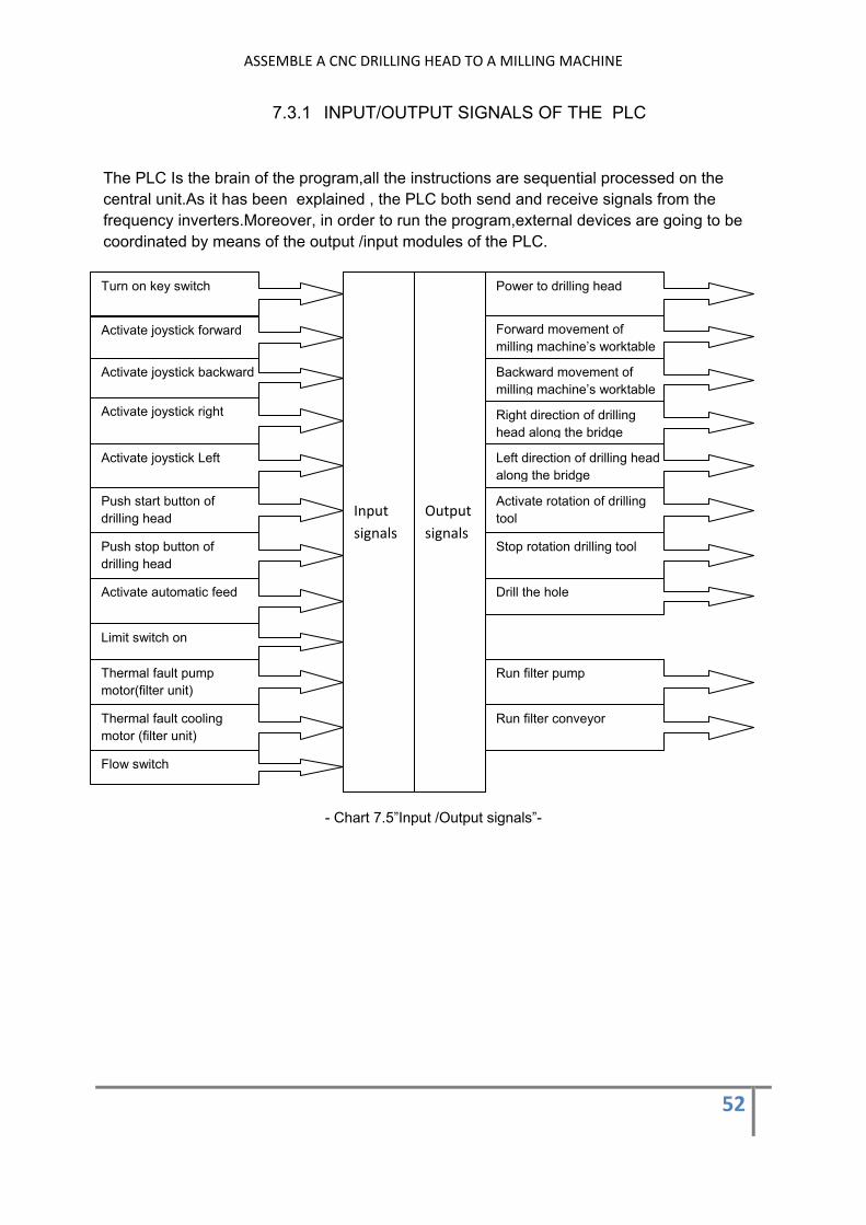
7.3.1 INPUT/OUTPUT SIGNALS OF THE PLC
The PLC Is the brain of the program,all the instructions are sequential processed on the central unit.As it has been explained , the PLC both send and receive signals from the frequency inverters.Moreover, in order to run the program,external devices are going to be coordinated by means of the output /input modules of the PLC.
- Chart 7.5”Input /Output signals”-
Power to drilling head
Input signals
Output signals
Forward movement of milling machine’s worktable
Backward movement of milling machine’s worktable
Right direction of drilling head along the bridge
Left direction of drilling head along the bridge
Activate rotation of drilling tool
Drill the hole
Stop rotation drilling tool
Run filter conveyor
Run filter pump
Turn on key switch
Activate joystick forward
Activate joystick backward
Activate joystick right
Activate joystick Left
Push start button of drilling head
Push stop button of drilling head
Limit switch on
Activate automatic feed
Thermal fault pump motor(filter unit)
Thermal fault cooling motor (filter unit)
Flow switch

ASSEMBLE A CNC DRILLING HEAD TO A MILLING MACHINE
53
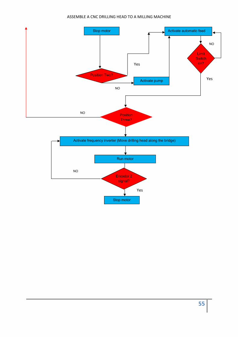
7.3.2 FLOW DIAGRAM OF THE PROGRAM The next step is to develop a flow diagram for the pattern that has been showed on figure7.3. Although the complete diagram is showed in Apppendix,a small version is explained. The diagram shows the process since the drilling mode is activated until the three first holes of the first row has been drilled. Once the drilling process is activated,the first goal is to achieve the starting point. For this reason, the joystick is used to move both the worktable and the drilling head along the bridge. Both encoders has counted the number of rotations of the motors.Before starting the automatic process, it is necessary to reset the two encoders. In order to reach the first hole, the drilling head is moved until the encoder counts the needed rotations of the shaft motor to be in the exactly position.The same process is followed to move the worktable.After it, the drilling tool is on the first position, so it is time to drill the first hole.The automatic feed of the drilling head is activated and the drilling tool start to go down.If the limit switch is on, it means that the drilling tool has finished the hole. Now, it is time to drill holes number two and three.When the hole number three has been drilled , the worktable is moved to start a new row.
Start
Drilling mode?
NO Switch on Key switch
Yes
Joystick
Move drilling head along bridge Move milling machine‘s worktable
Starting position?
NO
Yes Push reset button
Start rotation drilling tool
Activate pump

ASSEMBLE A CNC DRILLING HEAD TO A MILLING MACHINE
54
Activate frequency inverter (Move drilling head along the bridge)
Run motor
Activate automatic feed
Limit switch on?
Yes
Encoder 1 signal?
Activate frequency inverter (Move drilling head along the bridge)
Run motor
Encoder 1 signal?
NO
Stop motor
Yes
Activate frequency inverter (milling machine´s worktable)
Run motor
Encoder 2 signal?
NO
Stop motor
Yes
NO
NO
Yes
ASSEMBLE A CNC DRILLING HEAD TO A MILLING MACHINE
55
Activate automatic feed
Limit Switch
on?
Position Two?
Position Three?
Stop motor
Activate pump
Activate frequency inverter (Move drilling head along the bridge)
Run motor
Encoder 2 signal?
Stop motor
NO
Yes
Yes
NO
NO
NO
Yes

ASSEMBLE A CNC DRILLING HEAD TO A MILLING MACHINE
56
8 CONCLUSION In order to assemble the drilling head to the milling machine, an L-Shaped structure is built. It is strength enough, so the holes will be drilled properly. Moreover, a unit filter is used to supply water to the drilling head. The water will flow through a close-loop, that is composed of two tunnels and two pockets assembled to the milling machine. All the programs that will control the drilling process will be storage on the programmable logic controller (PLC). Likewise, the motors that drive both the drilling head along the bridge and the worktable are controlled by two frequency inverters. In order to coordinate the two working modes, it means drilling or milling mode, magnetic contactors, will be integrated in the new cabinet. Therefore, it will let control if the motors are activated by either the old milling cabinet or the new one. Finally, a program will be developed for a simple model to test it. The rows of holes will be drilled along the X axis because of the low weight of the drilling head with respect the worktable. A step drilling tool will be used for the drilling process in order o save time.
9-BIBLIOGRAPHY 1-Theodore Wildi;
Electrical machines, drives, and power systems Prectice Hall 1995 .Chapter 20 and chapter 31
2-Hugh Jack; Integration and automation of manufacturing systems
3-Mitsubishi Electric Website Programming Manual FX3U
ASSEMBLE A CNC DRILLING HEAD TO A MILLING MACHINE
57
10-APPENDICES
10.1 Appendix 1 ”Calculation of the screws”
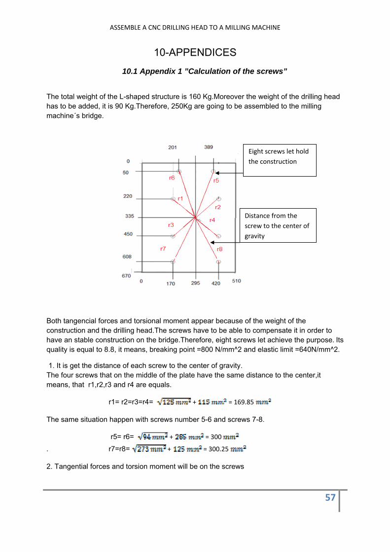
The total weight of the L-shaped structure is 160 Kg.Moreover the weight of the drilling head has to be added, it is 90 Kg.Therefore, 250Kg are going to be assembled to the milling machine´s bridge.
Both tangencial forces and torsional moment appear because of the weight of the construction and the drilling head.The screws have to be able to compensate it in order to have an stable construction on the bridge.Therefore, eight screws let achieve the purpose. Its quality is equal to 8.8, it means, breaking point =800 N/mm^2 and elastic limit =640N/mm^2.
1. It is get the distance of each screw to the center of gravity. The four screws that on the middle of the plate have the same distance to the center,it means, that r1,r2,r3 and r4 are equals.
r1= r2=r3=r4= + = 169.85
The same situation happen with screws number 5-6 and screws 7-8.
r5= r6= + = 300
. r7=r8= + = 300.25
2. Tangential forces and torsion moment will be on the screws
Eight screws let hold the construction
Distance from the screw to the center of gravity
ASSEMBLE A CNC DRILLING HEAD TO A MILLING MACHINE
58
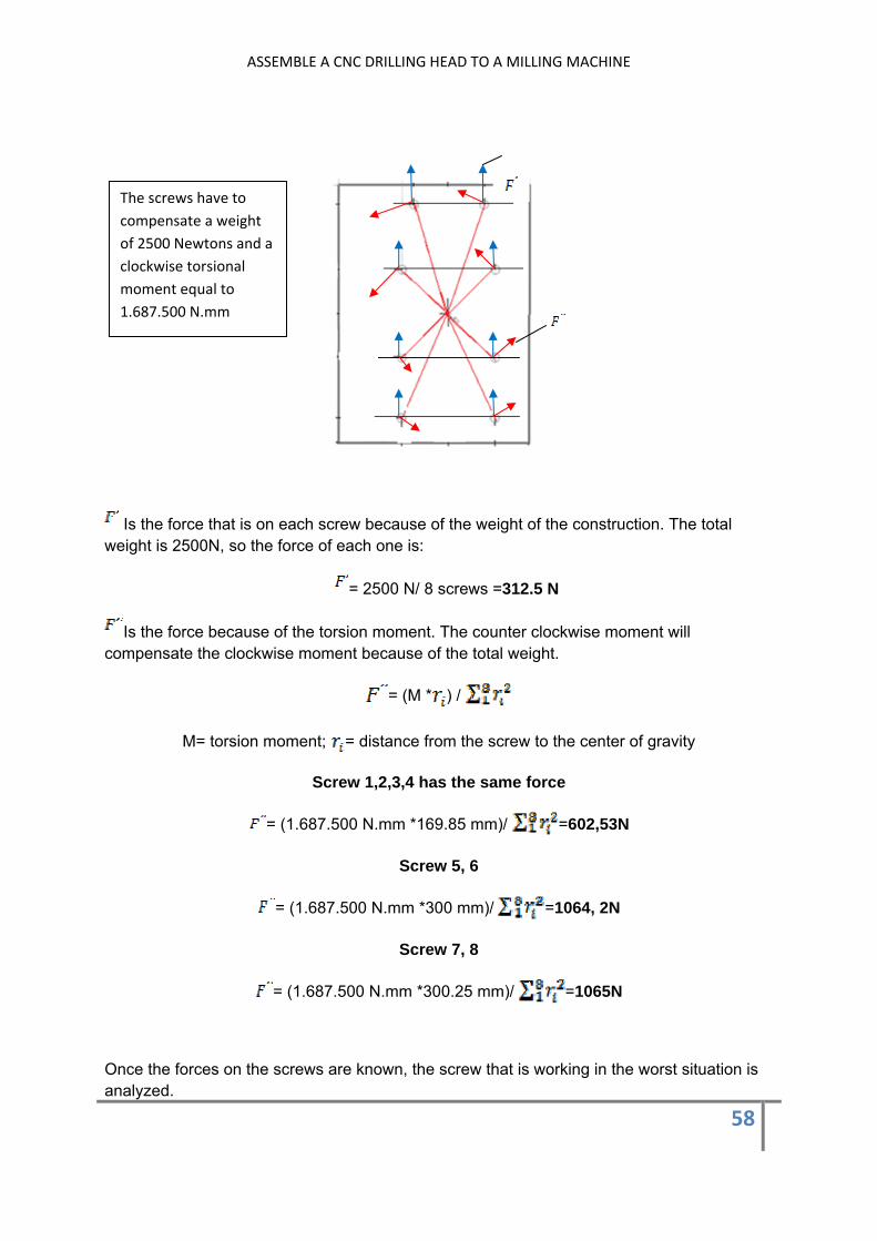
Is the force that is on each screw because of the weight of the construction. The total weight is 2500N, so the force of each one is:
= 2500 N/ 8 screws =312.5 N
Is the force because of the torsion moment. The counter clockwise moment will compensate the clockwise moment because of the total weight.
= (M * ) /
M= torsion moment; = distance from the screw to the center of gravity
Screw 1,2,3,4 has the same force
= (1.687.500 N.mm *169.85 mm)/ =602,53N
Screw 5, 6
= (1.687.500 N.mm *300 mm)/ =1064, 2N
Screw 7, 8
= (1.687.500 N.mm *300.25 mm)/ =1065N
Once the forces on the screws are known, the screw that is working in the worst situation is analyzed.
The screws have to compensate a weight of 2500 Newtons and a clockwise torsional moment equal to 1.687.500 N.mm
ASSEMBLE A CNC DRILLING HEAD TO A MILLING MACHINE
59
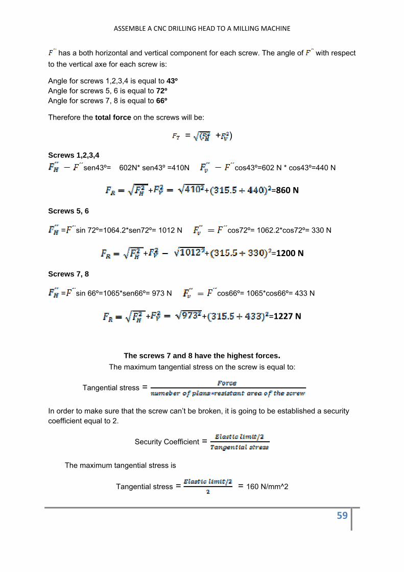
has a both horizontal and vertical component for each screw. The angle of with respect to the vertical axe for each screw is:
Angle for screws 1,2,3,4 is equal to 43º Angle for screws 5, 6 is equal to 72º Angle for screws 7, 8 is equal to 66º
Therefore the total force on the screws will be:
= + )
Screws 1,2,3,4 sen43º= 602N* sen43º =410N cos43º=602 N * cos43º=440 N
+ + =860 N
Screws 5, 6
= sin 72º=1064.2*sen72º= 1012 N cos72º= 1062.2*cos72º= 330 N
+ + =1200 N
Screws 7, 8
= sin 66º=1065*sen66º= 973 N cos66º= 1065*cos66º= 433 N
+ + =1227 N
The screws 7 and 8 have the highest forces. The maximum tangential stress on the screw is equal to:
Tangential stress =
In order to make sure that the screw can’t be broken, it is going to be established a security coefficient equal to 2.
Security Coefficient =
The maximum tangential stress is
Tangential stress = = 160 N/mm^2

ASSEMBLE A CNC DRILLING HEAD TO A MILLING MACHINE
60
Therefore, the maximum force that can be on the screw is:
Force= tangential stress *number plans* resistant area of the screw Maximum force = 160 N/mm^2 *2* 314.4 mm^2 = 100,500N
If it is compared the higher force that there is on the worst screw, it can be checked that is eighty times lower than the maximum force.

ASSEMBLE A CNC DRILLING HEAD TO A MILLING MACHINE
61
10.2 Appendix 2 ”Strenght of the structure”
In order to know if the structure is stiff enough, it is going to be analyzed the vertical displacement of the structure by means of the virtual work theorem.
-Picture A.2.1-
In the picture A.2.1 is showed a sketch of the L-shaped structure. Moreover, all the forces are showed. Both Q1 and Q2 are the own weight of the structure. In order to calculate Q1 and Q2, it is necessary to get the volume of the structure. Once it is known, the density of the material let know the force due to each arm of the structure. If the force is divided by the total length of each arm, both Q1 and Q2 are known.
Q1=0.48N/mm, Q2=0.73N/mm
P1 is the sum of the weight of the plate that closes the short arm of the construction and the drilling head. P1=1450N P2 is the weight of the plate that closes the long arm of the structure. All of these forces are downwards forces except R (on section B) that is an upward force in order to keep the equilibrium of the structure. Likewise, a counterclockwise torsion moment appears in section B with the same purpose. It has analyzed in the previous section.
The virtual work theorem is based on virtual system of forces. It let analyze both translational and rotational movements on structures. Therefore, if the vertical displacement of section A has to be known, a virtual system of forces has to be established.
A virtual force, whose numerical value is one, is put on section A. This section is where the drilling head is assembled to the construction. As can be checked, it is needed a force on section B in order to keep the equilibrium. In the same way, a counterclockwise torsion moment will appear is section B.
L1
Plate in contact with the bridge (Section B)
ASSEMBLE A CNC DRILLING HEAD TO A MILLING MACHINE
62
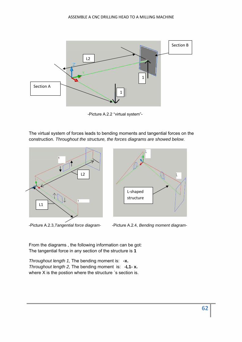
-Picture A.2.2 “virtual system”-
The virtual system of forces leads to bending moments and tangential forces on the construction. Throughout the structure, the forces diagrams are showed below.
-Picture A.2.3,Tangential force diagram- -Picture A.2.4, Bending moment diagram-
From the diagrams , the following information can be got: The tangential force in any section of the structure is 1
Throughout length 1, The bending moment is: -x. Throughout length 2, The bending moment is: -L1- x. where X is the postion where the structure ´s section is.
1
1Section A
L2
Section B
L1
L2
L‐shaped structure

ASSEMBLE A CNC DRILLING HEAD TO A MILLING MACHINE
63
The construction ,that is showed in picture A.2.1, leads to the following force diagrams.
-Picture A.2.5 Tangential force diagram- -Picture A.2.6 Bending moment diagram-
From the diagrams , the following information can be got: The tangential force in any section of the structure that is between 0 and L1 is: -1170-0.48X The tangential force in any section of the structure that is between 0 and L2 is: -1450-0.73X
Throughout length 1, the bending moment is:
Throughout length 2, the bending moment is:
The tangential forces can be neglected in order to calculate the displacement of section A.The reason is that the magnitude of the bending moments is higher.According to the virtual work theorem, the vertical displacement on section A is calculated below.
= * )/ E* ) dx
Where:
: Bending moments on virtual system
: Bending moment real system [N.mm]
: Inertia [mm^4]
E: Steel young´s module [N/mm^2]
+ ) = +
+ +
)=
1170N
2500N
1450N
M=773844N.mm

ASSEMBLE A CNC DRILLING HEAD TO A MILLING MACHINE
64
= +0.06 )+ +72 +386922 +
483 +0.09 ) = + ) =
Therefore:
The inertia of the section is calculated below
The section A is composed of the area of five rectangles.The sum of each inertia is equal to the total inertia .
-Picture A.2.7 Sketch of section A-
Inertia Rectangle 1
= 1/12*380 mm*2.5 mm^3 = 495 mm^4
Steiner theorem:
= + area*d^2 -> =2*( +1900 * )=175655988
Rectangle 1
Rectangle 2
Rectangle 3
Rectangle 4
A Z Axis
ASSEMBLE A CNC DRILLING HEAD TO A MILLING MACHINE
65
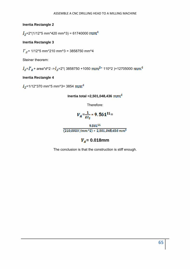
Inertia Rectangle 2
=2*(1/12*5 mm*420 mm^3) = 61740000
Inertia Rectangle 3
= 1/12*5 mm*210 mm^3 = 3858750 mm^4
Steiner theorem:
= + area*d^2 -> =2*( 3858750 +1050 * 110^2 )=12705000
Inertia Rectangle 4
=1/12*370 mm*5 mm^3= 3854
Inertia total =2,501,048,436
Therefore:
= =
= 0.018mm
The conclusion is that the construction is stiff enough.
ASSEMBLE A CNC DRILLING HEAD TO A MILLING MACHINE
66
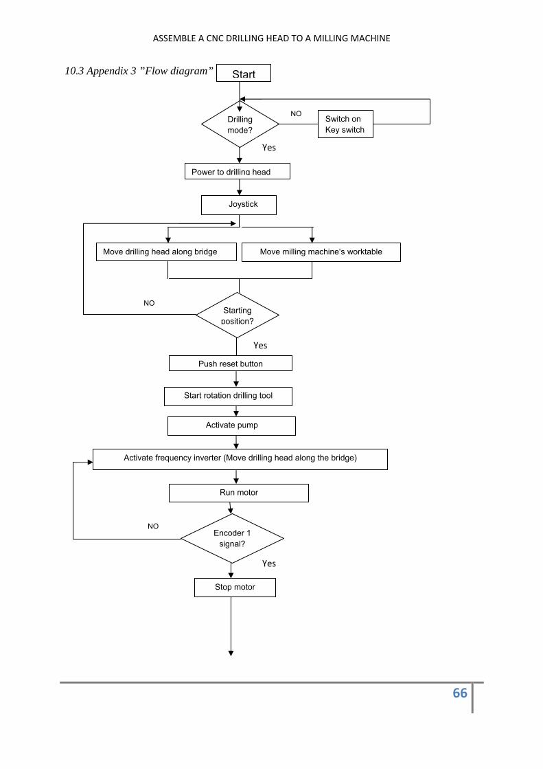
10.3 Appendix 3 ”Flow diagram”
Start
Drilling mode?
NOSwitch on Key switch
Power to drilling head
Yes
Joystick
Move drilling head along bridge Move milling machine‘s worktable
Starting position?
NO
Yes
Push reset button
Start rotation drilling tool
Activate pump
Activate frequency inverter (Move drilling head along the bridge)
Run motor
Encoder 1 signal?
NO
Stop motor
Yes

ASSEMBLE A CNC DRILLING HEAD TO A MILLING MACHINE
67
Activate frequency inverter (Move drilling head along the bridge)
Run motor
Position Two?
Activate automatic feed
Switch on?
Activate automatic feed
Limit switch on?
Yes
Encoder 1 signal?
NO
Yes
Stop motor Activate pump
activate Pump
Activate frequency inverter (milling machine´s worktable)
Run motor
Encoder 2 signal?
NO
Stop motor
NO
Position Three?
Yes
Yes
NO
NO Yes
Yes
*

ASSEMBLE A CNC DRILLING HEAD TO A MILLING MACHINE
68
Activate frequency inverter (Move drilling head along the bridge)
Run motor
Encoder 1 signal?
NO
Yes
Yes
Activate automatic feed
Limit Switch on?
Position four?
NO
Activate Pump
Position six?
Yes
Yes
Position five?
NO
Yes NO
Activate Pump
NO
Yes

ASSEMBLE A CNC DRILLING HEAD TO A MILLING MACHINE
69
Reverse rotational speed on frequency inverter (Drilling head)
Activate frequency inverter (milling machine´s worktable)
Encoder 2 signal?
Run motor
NO
Stop motor
Activate pump
Yes
Activate automatic feed
Switch on?
NO
Activate frequency inverter (Move drilling head along the bridge)
Run motor
Encoder 1 signal?
NO
Stop motor
Yes
Yes
ASSEMBLE A CNC DRILLING HEAD TO A MILLING MACHINE
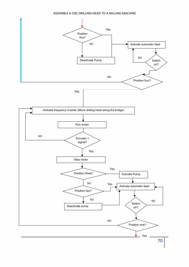
70
Position five?
Activate automatic feed
Switch on?
NO
NO Deactivate Pump
Position four?
Yes
Yes
NO
Activate frequency inverter (Move drilling head along the bridge)
Run motor
Encoder 1 signal?
NO
Yes
Activate automatic feed
Switch on?
Position three? Activate Pump
Position one?
Yes
Yes
Position two?
NO
NO
Stop motor
Yes
NO
Deactivate pump
NO

ASSEMBLE A CNC DRILLING HEAD TO A MILLING MACHINE
71
Both first and second row has been drilled. The drilling tool is going to start the third row row . The cycle is going to be repeated
Reverse rotational speed on frequency inverter (Drilling head)
Activate frequency inverter (milling machine´s worktable)
Run motor
Encoder 2 signal?
Stop motor
Yes
NO
*
*
Related Documents