Drive System for Decentralized Installation AS-i Interfaces and Field Distributors Edition 04/2003 Manual 10565116 / EN

Welcome message from author
This document is posted to help you gain knowledge. Please leave a comment to let me know what you think about it! Share it to your friends and learn new things together.
Transcript

Drive System for Decentralized InstallationAS-i Interfaces and Field Distributors
Edition
04/2003
Manual10565116 / EN

SEW-EURODRIVE

Contents
Manual – AS-i Interfaces and Field Distributors 3
1 Valid Components............................................................................................. 5
2 Important Notes................................................................................................. 6
3 Safety Notes ...................................................................................................... 83.1 Safety notes for MOVIMOT® drives ......................................................... 83.2 Additional safety instructions for field distributors ..................................... 9
4 Unit Design ...................................................................................................... 104.1 Fieldbus interfaces.................................................................................. 104.2 Type designation of AS-i interfaces ........................................................ 124.3 Field distributors...................................................................................... 134.4 Type designation of AS-i field distributors............................................... 174.5 MOVIMOT® frequency inverters (integrated in Z.7/Z.8 field distributors)19
5 Mechanical Installation................................................................................... 205.1 Installation instructions............................................................................ 205.2 MF../MQ.. fieldbus interfaces .................................................................. 215.3 Field distributors...................................................................................... 24
6 Electrical Installation ...................................................................................... 306.1 Installation planning under EMC aspects................................................ 306.2 Installation instructions fieldbus interfaces, field distributors .................. 326.3 AS-i cable connection ............................................................................. 376.4 Connection with double tap..................................................................... 386.5 Connection with single tap and 24 V loop............................................... 416.6 Connection of inputs / outputs (I/O) of MFK.. AS-i interfaces ............... 446.7 Connection of pre-fabricated cables ....................................................... 46
7 Startup.............................................................................................................. 487.1 Startup procedure ................................................................................... 487.2 Assignment of AS-i address via an addressing device ........................... 49
8 Function of the MFK.. AS-i Interface ............................................................. 508.1 Overview of function modules................................................................. 508.2 Description of function modules.............................................................. 518.3 Index assignment of the function modules.............................................. 558.4 Parameter transfer notes ........................................................................ 558.5 Write parameter string ............................................................................ 568.6 Read parameter string ............................................................................ 568.7 Read diagnostics .................................................................................... 578.8 MFK system fault / MOVIMOT® fault...................................................... 588.9 Meaning of the LED display .................................................................... 59
9 Supplemental Field Distributor Startup Information ................................... 619.1 Field distributor MF.../Z.6., MQ.../Z.6. ..................................................... 619.2 Field distributors MF.../MM../Z.7., MQ.../MM../Z.7. ................................. 629.3 MF.../MM../Z.8., MQ.../MM../Z.8. field distributors .................................. 639.4 MOVIMOT® frequency inverter integrated in field distributor ................ 65
10 MFG11A Keypad.............................................................................................. 6610.1 Function .................................................................................................. 6610.2 Operation ................................................................................................ 67
11 MOVILINK® Unit Profile.................................................................................. 68

Contents
4 Manual – AS-i Interfaces and Field Distributors
12 MFK Diagnostics ............................................................................................. 7112.1 MFK diagnostics interface....................................................................... 71
13 MOVIMOT® Diagnostics ................................................................................. 7413.1 Status LED.............................................................................................. 7413.2 Table of errors......................................................................................... 75
14 Technical Data................................................................................................. 7614.1 MFK.. AS-i interface................................................................................ 7614.2 Field distributors...................................................................................... 77
Index................................................................................................................. 80

Manual – AS-i Interfaces and Field Distributors 5
1Valid Components
1 Valid ComponentsThis manual applies to the following products:
..Z.1. connection module with fieldbus interface
4 x I / 2 x O (terminals) 4 x I / 2 x O (M12)
ASi MFK 21A / Z61A MFK 22A / Z61A
..Z.3. field distributor with fieldbus interface
4 x I / 2 x O (terminals) 4 x I / 2 x O (M12)
ASi MFK 21A / Z63A MFK 22A / Z63A
..Z.6. field distributor with fieldbus interface
4 x I / 2 x O (terminals) 4 x I / 2 x O (M12)
ASi MFK 21A / Z66F / AF6 MFK 22A / Z66F / AF6
..Z.7. field distributor with fieldbus interface
4 x I / 2 x O (terminals) 4 x I / 2 x O (M12)
ASi MFK21A/MM../Z67F. MFK22A/MM../Z67F.
..Z.8. field distributor with fieldbus interface
4 x I / 2 x O (terminals) 4 x I / 2 x O (M12)
ASi MFK21A/MM../Z68F./AF6 MFK22A/MM../Z68F./AF6
2
6 Manual – AS-i Interfaces and Field Distributors
Important Notes
2 Important NotesSafety and warn-ing instructions
Always follow the safety and warning instructions contained in this publication!
Other applicable documents
• Operating Instructions "MOVIMOT® MM03C to MM3XC"
• Operating Instructions "DR/DT/DV AC Motors, CT/CV Asynchronous Servomotors"
• If MOVIMOT® is used for emergency stops, the supplemental documentation"Safe Disconnection for MOVIMOT®" must be observed. Only those compo-nents may be used in safety applications that were explicitly delivered with thisdesign by SEW-EURODRIVE!
Intended usage • These MOVIMOT® drives are intended for industrial systems. They comply with theapplicable standards and regulations and meet the requirements of the Low VoltageDirective 73/23/EEC.
• The use of MOVIMOT® for hoist applications is limited!
• Technical data and information about the permitted conditions where the unit is usedcan be found on the nameplate and in these operating instructions.
• It is essential to observe this specified information!
• Do not start up the unit (take it into operation in the designated fashion) until you haveestablished that the machine complies with the EMC Directive 89/336/EEC and thatthe conformity of the end product has been determined in accordance with the Ma-chinery Directive 89/392/EEC (with reference to EN 60204).
Electrical hazardPossible consequences: Severe or fatal injuries.
Hazard Possible consequences: Severe or fatal injuries.
Hazardous situationPossible consequences: Slight or minor injuries.
Harmful situationPossible consequences: Damage to the unit and the environment.
Tips and useful information.

Manual – AS-i Interfaces and Field Distributors 7
2Important Notes
Application envi-ronment
The following uses are forbidden unless measures are expressly taken to makethem possible:
• Use in explosion-proof areas
• Use in areas exposed to harmful oils, acids, gases, vapors, dust, radiation, etc.
• Use in non-stationary applications which are subject to mechanical vibration andshock loads in excess of the requirements in EN 50178
• Use in applications in which the MOVIMOT® inverter undertakes independent safetyfunctions (without master safety systems) to ensure the safety of machines and per-sonnel
Waste disposal This product consists of:
• Iron
• Aluminum
• Copper
• Plastic
• Electronic components
Dispose of all components in accordance with applicable regulations!

3
8 Manual – AS-i Interfaces and Field Distributors
Safety notes for MOVIMOT® drivesSafety Notes
3 Safety Notes
3.1 Safety notes for MOVIMOT® drives
• Never install damaged products or take them into operation. Please submit a com-plaint to the shipping company immediately in the event of a damage.
• Only specialists with the appropriate accident prevention training are allowed to per-form installation, startup and service work. These specialist must also comply withthe regulations in force (e.g. EN 60204, VBG 4, DIN-VDE 0100/0113/0160) whenperforming this work.
• Preventive measures and protection devices must correspond to the regulations inforce (e.g. EN 60204 or EN 50178).
Necessary protective measures: Grounding of the MOVIMOT® unit and the field dis-tributor.
• The unit meets all requirements for safe isolation of power and electronic connec-tions in accordance with EN 50178. All connected circuits must also satisfy the re-quirements for safe disconnection.
• Before removing the MOVIMOT® inverter, it must be disconnected from the powersupply system. Dangerous voltages may still be present for up to one minute afterdisconnection from the power supply source.
• As soon as supply voltage is present at the MOVIMOT® unit or field distributor, closethe terminal box or field distributor and install the MOVIMOT® inverter.
• The fact that the status LED and other display elements are no longer illuminateddoes not indicate that the unit has been disconnected from the power supply and nolonger carries any voltage.
• Mechanical blocking or internal safety functions of the unit can cause a motor stand-still. Removing the cause of this problem or performing a reset can result in the motorre-starting on its own. If, for safety reasons, this is not permitted for the driven ma-chine, the MOVIMOT® inverter must be disconnected from the power supply beforecorrecting the problem.
• Danger of burns: The surface temperature of the MOVIMOT® inverter (especially ofthe heat sink) can exceed 60 °C during operation!
• If MOVIMOT® or field distributors are used in safe applications, you must observethe supplemental documentation "Safe Disconnection for MOVIMOT®". Use onlythose components in safety applications that were explicitly delivered in this designby SEW-EURODRIVE!

Manual – AS-i Interfaces and Field Distributors 9
3Additional safety instructions for field distributorsSafety Notes
3.2 Additional safety instructions for field distributors
MFZ.3. • Disconnect the unit from the power supply system before removing the bus moduleor the motor plug. Dangerous voltages may still be present for up to one minute afterdisconnection from the power supply source.
• The bus module and the plug of the hybrid cable must be connected to the field dis-tributor and fastened during operation.
MFZ.6. • Disconnect the unit from the power supply system before removing the terminal boxcover for connection to the power supply system. Dangerous voltages may still bepresent for up to one minute after disconnection from the power supply source.
• Important: The switch only disconnects the MOVIMOT® unit from the power supplysystem. The terminals of the field distributor are still connected to the power supplysystem after operating the maintenance switch.
• The cover on that part of the terminal box housing the connection to the power supplymust be closed; the plug of the hybrid cable must be connected to the field distributorand fastened during operation.
MFZ.7. • Before removing the MOVIMOT® inverter, it must be disconnected from the powersupply system. Dangerous voltages may still be present for up to one minute afterdisconnection from the power supply source.
• The MOVIMOT® inverter and the plug of the hybrid cable must be connected to thefield distributor and fastened during operation.
MFZ.8. • Disconnect the unit from the power supply system before removing the terminal boxcover for the power supply connection or the MOVIMOT® inverter. Dangerous volt-ages may still be present for up to one minute after disconnection from the powersupply source.
• Important: The maintenance switch only disconnects the connected motor from thepower supply system. The terminals of the field distributor remain connected to thepower supply system even after operation of the maintenance switch.
• The terminal box cover for the power supply connection, the MOVIMOT<:cs "Prod-name" 1>® inverter and the plug of the hybrid cable must be connected to the fielddistributor and fastened during operation.®

4
10 Manual – AS-i Interfaces and Field Distributors
Fieldbus interfacesUnit Design
4 Unit Design4.1 Fieldbus interfaces
MF.21/MQ.21 fieldbus inter-faces
MF.22, MF.32, MQ.22, MQ.32 fieldbus inter-faces
50353AXX
1 Diagnostic LEDs2 Diagnostics interface (below the screw plug)
1
2
50352AXX
1 Diagnostic LEDs2 Diagnostics interface (below the screw plug)3 M12 connection sockets4 Status LED
1
2
3
4

Manual – AS-i Interfaces and Field Distributors 11
4Fieldbus interfacesUnit Design
Bottom of module (all MF../MQ.. vari-ants)
Unit design of MFZ connection module
01802CDE
1 Connection to connection module2 DIP switches (depend on variant)3 Gasket
2
3
1
06169AXX
1 Terminal strip (X20)2 Insulated terminal block for 24 V through-wiring
(Caution! Do not use for shielding!)3 Cable gland M204 Cable gland M125 Grounding terminal6 For DeviceNet and CANopen: Micro-style connector/M12 connector (X11)
For AS interface: AS-i M12 connector (X11)
The scope of delivery includes two EMC cable glands.
63
5
4
3
4
2
31

4
12 Manual – AS-i Interfaces and Field Distributors
Type designation of AS-i interfacesUnit Design
4.2 Type designation of AS-i interfaces
MFK 21 A / Z61 A
Design
Connection module:Z11 = for InterBusZ21 = for PROFIBUSZ31 = for DeviceNet and CANopenZ61 = for AS-i
Design
21 = 4 x I / 2 x O (connection via terminals)22 = 4 x I / 2 x O (connection via plug connector + terminals)32 = 6 x I (connection via plug connector + terminals)
23 = 4 x I / 2 x O (FO rugged line, for InterBus only)33 = 6 x I (FO rugged line, for InterBus only)
MFI.. = InterBusMQI.. = Intelligent InterBus fieldbus moduleMFP.. = PROFIBUSMQP.. = Intelligent PROFIBUS fieldbus moduleMFD.. = DeviceNetMQD.. = Intelligent DeviceNet fieldbus moduleMFO.. = CANopenMFK.. = AS-i

Manual – AS-i Interfaces and Field Distributors 13
4Field distributorsUnit Design
4.3 Field distributors
MF.../Z.3., MQ.../Z.3. field distributors
05108AXX
1 2 x M16 x 1.5 (scope of delivery includes two EMC cable glands)2 2 x M25 x 1.53 2 x M20 x 1.54 Equipotential bonding connection5 Connection hybrid cable, connection to MOVIMOT® (X9)6 Terminals for fieldbus connections (X20)7 Terminals for 24 V connection (X21)8 Terminals for power supply system and PE connection (X1)9 For DeviceNet and CANopen: Micro-style connector/M12 connector (X11)
For AS interface: AS-i M12 connector (X11)
9
1
2
3
4
1
22
3
4
8
6 7
5

4
14 Manual – AS-i Interfaces and Field Distributors
Field distributorsUnit Design
MF.../Z.6., MQ.../Z.6. field distributors
05903AXX
1 Connection hybrid cable, connection to MOVIMOT® (X9)2 Equipotential bonding connection3 Maintenance switch with line protection (triple lock, color: black/red)
03546AXX4 Terminals for supply system and PE connection (X1)5 2 x M25 x 1.56 Terminals for bus, sensor, actuator, 24 V connection (X20)7 6 x M20 x 1.5 (scope of delivery includes two EMC cable glands)
For DeviceNet and CANopen: Micro-style connector/M12 connector (X11), see the following figureFor AS interface: AS-i M12 connector (X11), see the following figure
06115AXX8 Terminal block for 24 V through-wiring (X29), internal connection to 24 V on X209 Pluggable terminal "Safety Power" for 24 V MOVIMOT® supply (X40)
1 2 3 4 5 6 7 9 2 8
I ON I ON
0 OF
F
0 OF
F
Ø 5...Ø 8 mm

Manual – AS-i Interfaces and Field Distributors 15
4Field distributorsUnit Design
MF.../MM../Z.7., MQ.../MM../Z.7. field distributors
51174AXX
1 MOVIMOT® frequency inverter2 Connection hybrid cable, connection to AC motor (X9)3 Equipotential bonding connection4 Terminals for bus, sensor, actuator, 24 V connection (X20)5 Pluggable terminal "Safety Power" for 24 V MOVIMOT® supply (X40)6 5 x M20 x 1.5 cable gland (scope of delivery includes two EMC cable glands)
For DeviceNet and CANopen: Micro-style connector/M12 connector (X11), see the following figureFor AS interface: AS-i M12 connector (X11), see the following figure
51325AXX7 Terminal block for 24 V through-wiring (X29), internal connection to 24 V on X208 2 x M25 x 1.5 cable screw fittings9 Terminals for power supply system and PE connection (X1)10 Connection to frequency inverter11 Terminal for integrated braking resistor12 Terminals to enable direction of rotation

4
16 Manual – AS-i Interfaces and Field Distributors
Field distributorsUnit Design
MF.../MM../Z.8., MQ.../MM../Z.8. field distributors
05902AXX
1 Terminals for power supply system and PE connection (X1)2 Maintenance switch (triple lock, color: black/red)
03546AXX3 2 x M25 x 1.5 cable screw fittings4 Terminals for bus, sensor, actuator, 24 V connection (X20)5 6 x M20 x 1.5 cable gland (scope of delivery includes two EMC cable glands)
For DeviceNet and CANopen: Micro-style connector/M12 connector (X11), see the following figureFor AS interface: AS-i M12 connector (X11), see the following figure
06115AXX6 MOVIMOT® frequency inverter7 Equipotential bonding connection8 Connection hybrid cable, connection to AC motor (X9)9 Terminal block for 24 V through-wiring (X29), internal connection to 24 V on X2010 Pluggable terminal "Safety Power" for 24 V MOVIMOT® supply (X40)
3 5 7
8
62
1
4
10
9
I ON I ON
0 OF
F
0 OF
F
Ø 5...Ø 8 mm
Manual – AS-i Interfaces and Field Distributors 17
4Type designation of AS-i field distributorsUnit Design
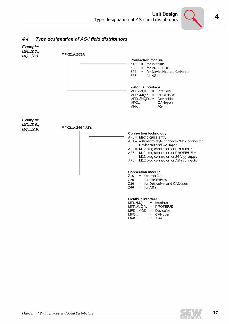
4.4 Type designation of AS-i field distributors
Example: MF.../Z.3., MQ.../Z.3.
Example: MF.../Z.6., MQ.../Z.6.
MFK21A/Z63A
Connection moduleZ13 = for InterBusZ23 = for PROFIBUSZ33 = for DeviceNet and CANopenZ63 = for AS-i
Fieldbus interfaceMFI../MQI.. = InterBusMFP../MQP.. = PROFIBUSMFD../MQD.. = DeviceNetMFO.. = CANopenMFK.. = AS-i
MFK21A/Z66F/AF6
Connection technologyAF0 = Metric cable entryAF1 = with micro-style connector/M12 connector
DeviceNet and CANopenAF2 = M12 plug connector for PROFIBUSAF3 = M12 plug connector for PROFIBUS +
M12 plug connector for 24 VDC supplyAF6 = M12 plug connector for AS-i connection
Connection moduleZ16 = for InterBusZ26 = for PROFIBUSZ36 = for DeviceNet and CANopenZ66 = for AS-i
Fieldbus interfaceMFI../MQI.. = InterbusMFP../MQP.. = PROFIBUSMFD../MQD.. = DeviceNetMFO.. = CANopenMFK.. = AS-i

4
18 Manual – AS-i Interfaces and Field Distributors
Type designation of AS-i field distributorsUnit Design
Example: MF.../MM../Z.7., MQ.../MM../Z.7.
Example: MF.../MM../Z.8., MQ.../MM../Z.8.
MFK22A/MM15C-503-00/Z67F 0
Circuit type0 = / 1=
Connection moduleZ17 = for InterBusZ27 = for PROFIBUSZ37 = for DeviceNet and CANopenZ67 = for AS-i
MOVIMOT® inverter
Fieldbus interfaceMFI../MQI.. = InterBusMFP../MQP.. = PROFIBUSMFD../MQD.. = DeviceNetMFO.. = CANopenMFK.. = AS-i
MFK22A/MM22C-503-00/Z68F 0/AF6
Connection technologyAF0 = Metric cable entryAF1 = with micro-style connector/M12 connector
DeviceNet and CANopenAF2 = M12 plug connector for PROFIBUSAF3 = M12 plug connector for PROFIBUS +
M12 plug connector for 24 VDC supplyAF6 = M12 plug connector for AS-i connection
Circuit type0 = / 1=
Connection moduleZ18 = for InterBusZ28 = for PROFIBUSZ38 = for DeviceNet and CANopenZ68 = for AS-i
MOVIMOT® inverter
Fieldbus interfaceMFI../MQI.. = InterBusMFP../MQP.. = PROFIBUSMFD../MQD.. = DeviceNetMFO.. = CANopenMFK.. = AS-i

Manual – AS-i Interfaces and Field Distributors 19
4MOVIMOT® frequency inverters (integrated in Z.7/Z.8 field distributors)Unit Design
4.5 MOVIMOT® frequency inverters (integrated in Z.7/Z.8 field distributors)
05900AXX
1. Heat sink2. Connection plug between connection unit and inverter3. Electronics nameplate4. Safety hood for inverter electronics5. Setpoint potentiometer f1 (not shown), accessible through a cable gland on top of the termi-
nal box cover6. Setpoint switch f2 (green)7. Switch t1 for generator ramp (white)8. DIP switches S1 and S2 (for settings see the section "Startup")9. Status LED (visible from the top of the terminal box cover, see the section "Diagnostics")
3 4 5 6 7 8 91 2

5
20 Manual – AS-i Interfaces and Field Distributors
Installation instructionsMechanical Installation
5 Mechanical Installation5.1 Installation instructions
Installation • Install fieldbus interfaces and field distributors on a level, vibration-proof and torsion-ally rigid support structure.
• Use M5 screws and suitable washers for installation of the MFZ.3 field distributor.Tighten the screws with a torque wrench (permitted tightening torque 2.8 to 3.1 Nm).
• Use M6 screws and suitable washers for installation of the MFZ.6, MFZ.7 or MFZ.8field distributor. Tighten the screws with a torque wrench (permitted tightening torque3.1 to 3.5 Nm).
Installation in damp areas or in the open
• Use suitable cable glands (use reducing adapters if necessary).
• Cover open cable entries and M12 connection sockets with screw plugs.
• Route the cable with a drip loop if the cable entry is located on the side.
• Check the sealing surfaces before reassembling the bus module / terminal box cov-er. Clean the sealing surfaces, if necessary.
In the delivery state of field distributors, the plug connector of the outgoing motorcircuit (hybrid cable) is equipped with a transportation protection.
This protection only ensures enclosure IP 40. To obtain the specified enclosuretype, remove the transportation protection, install and fasten the appropriate mat-ing connector.

Manual – AS-i Interfaces and Field Distributors 21
5MF../MQ.. fieldbus interfacesMechanical Installation
5.2 MF../MQ.. fieldbus interfaces
The MF../MQ.. fieldbus interfaces can be assembled as follows:
• Installation on MOVIMOT® terminal box
• Installation in the field
Installation on MOVIMOT® termi-nal box
1. Remove knock-outs on MFZ bottom from the inside as illustrated in the following fig-ure:
51249AXX
MFZ..

5
22 Manual – AS-i Interfaces and Field Distributors
MF../MQ.. fieldbus interfacesMechanical Installation
2. Install the fieldbus interface to the MOVIMOT® terminal box according to the follow-ing figure:
51250AXX
MF../MQ..
MF../MQ..
MFZ..

Manual – AS-i Interfaces and Field Distributors 23
5MF../MQ.. fieldbus interfacesMechanical Installation
Installation in the field
The following figure shows the installation of an MF../MQ.. fieldbus interface in the field:
51248AXX
82,5
mm
102 mm
51 mm
M4
M4
MFZ...
MF../MQ..
MF../MQ..

5
24 Manual – AS-i Interfaces and Field Distributors
Field distributorsMechanical Installation
5.3 Field distributors
Installation of MF.../Z.3., MQ.../Z.3. field distributors
The following figure shows the mounting dimensions of the ..Z.3. field distributors:
51219AXX
50 mm
100 mm
M5
M5
17
5 m
m
Manual – AS-i Interfaces and Field Distributors 25
5Field distributorsMechanical Installation
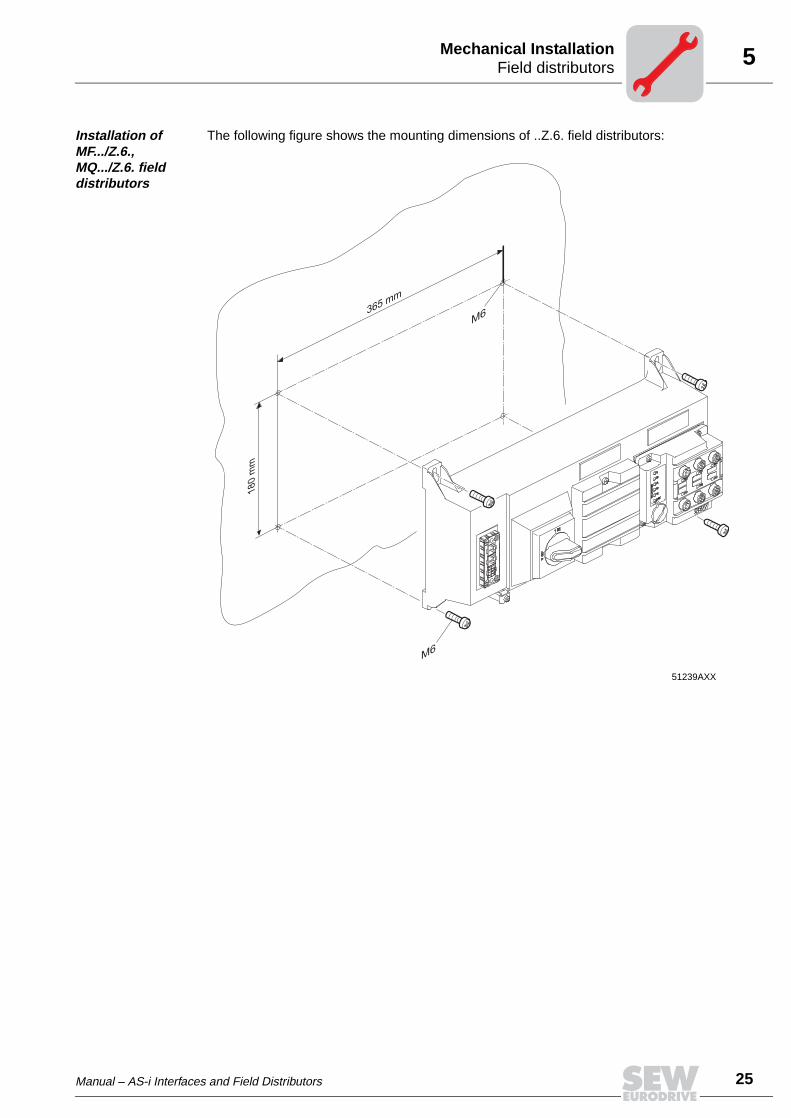
Installation of MF.../Z.6., MQ.../Z.6. field distributors
The following figure shows the mounting dimensions of ..Z.6. field distributors:
51239AXX
M6
M6
365 mm
180 m
m

5
26 Manual – AS-i Interfaces and Field Distributors
Field distributorsMechanical Installation
Installation of MF.../MM../Z.7., MQ.../MM../Z.7. field distributors
The ..Z.7. field distributors can be mounted as follows:
• Assembly on C-profile rail
• Wall mounting
"Wall mounting" The following figure shows the wall-mounting dimensions for ..Z.7. field distributors:
51243AXX
59,5
mm
253.7 mm
M6
M6
Manual – AS-i Interfaces and Field Distributors 27
5Field distributorsMechanical Installation
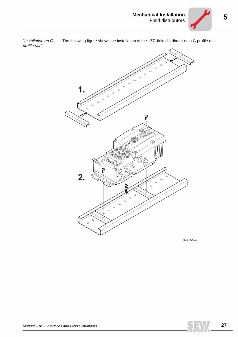
"Installation on C-profile rail"
The following figure shows the installation of the ..Z7. field distributor on a C-profile rail:
51175AXX
1.
2.

5
28 Manual – AS-i Interfaces and Field Distributors
Field distributorsMechanical Installation
Installation of the MF.../MM03-MM15/Z.8., MQ.../MM03-MM15/Z.8. field distributors (size 1)
The following figure shows the mounting dimensions of ..Z.8. field distributor: (size 1):
51173AXX
290 m
m
200 mm
M6
M6

Manual – AS-i Interfaces and Field Distributors 29
5Field distributorsMechanical Installation
Installation of MF.../MM22-MM3X/Z.8., MQ.../MM22-MM3X/Z.8. field distributors (size 2)
The following figure shows the mounting dimensions of ..Z.8. field distributor: (size 2):
51222AXX
35
0m
m
205 mm
M6
M6

6
30 Manual – AS-i Interfaces and Field Distributors
Installation planning under EMC aspectsElectrical Installation
6 Electrical Installation6.1 Installation planning under EMC aspects
Notes on arrang-ing and routing installation com-ponents
Selecting the correct cables, providing correct grounding and a functioning equipotentialbonding system are decisive factors in achieving a successful installation of decentral-ized drives.
The relevant standards must be applied in all cases. Particular attention should alsobe paid to the following points:
• Equipotential bonding
– Low-impedance HF-capable potential compensation must be provided indepen-dent of the functional ground (PE terminal) (see also VDE 0113 or VDE 0100 Part540) through, for example through:– Flat contact surface connection of metal (system) components– Use of ribbon grounding electrodes (RF litz wire)
– The cable shield of data cables must not be used for equipotential bonding.
• Data lines and 24V dc supply
– These lines must be routed separately from cables subject to interference (suchas control cables for solenoid valves, motor feeders).
• Field distributors
– We recommend using pre-fabricated SEW hybrid cables especially designed forthe connection of field distributors and motors.
• Cable glands
– Select a cable gland with large contact surface shield (consult the notes on selec-tion and appropriate assembly of cable glands).
• Cable shield
– This component must exhibit good EMC characteristics (high shield attenuation).– It may not serve as mere mechanical protection for the cable.– It must be connected with metal housing of the unit (via EMC metal cable glands)
at the flat contact surface cable ends (consult the notes on selection and appro-priate assembly of cable glands).
• Additional information is available in the SEW publication "Drive Engineering– Practical Implementation, Electromagnetic Compatibility (EMC) in Drive En-gineering."
03643AXX
03047AXX
Manual – AS-i Interfaces and Field Distributors 31
6Installation planning under EMC aspectsElectrical Installation
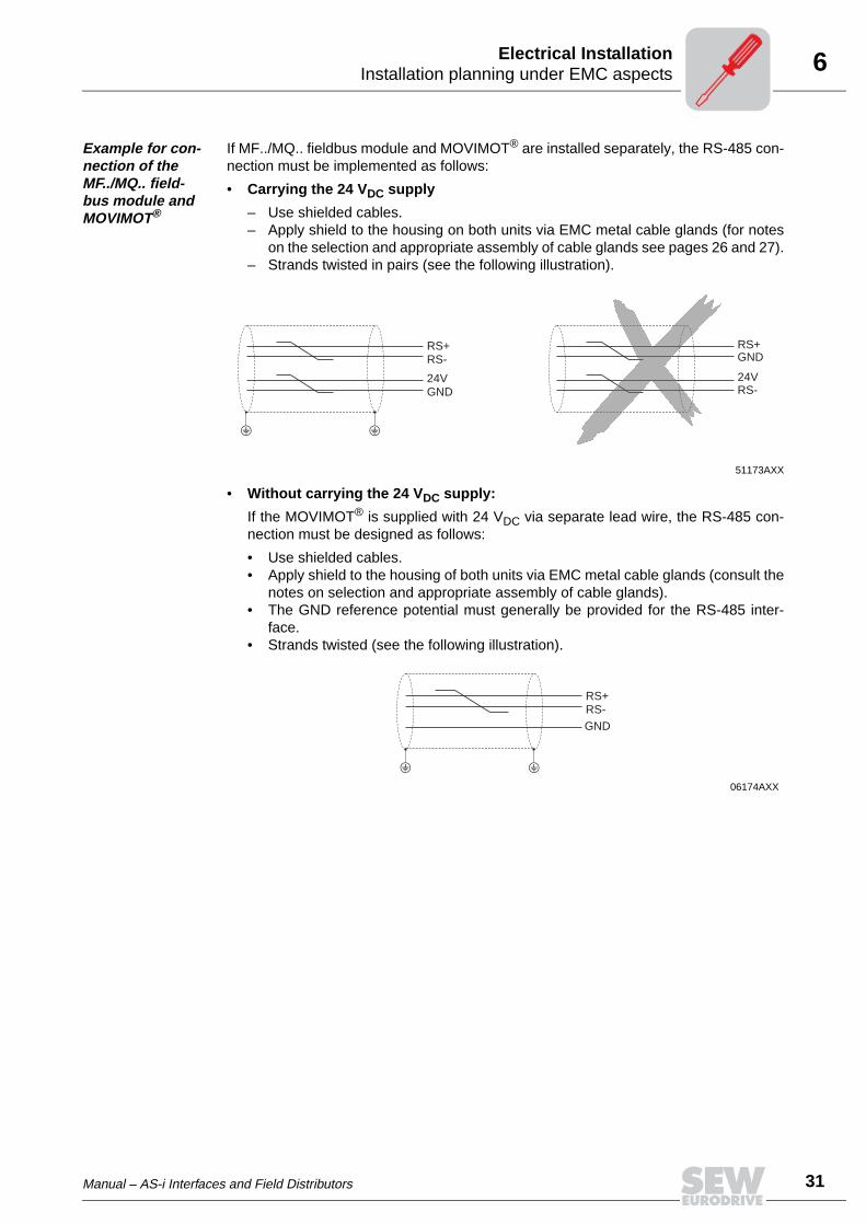
Example for con-nection of the MF../MQ.. field-bus module and MOVIMOT®
If MF../MQ.. fieldbus module and MOVIMOT® are installed separately, the RS-485 con-nection must be implemented as follows:
• Carrying the 24 VDC supply
– Use shielded cables.– Apply shield to the housing on both units via EMC metal cable glands (for notes
on the selection and appropriate assembly of cable glands see pages 26 and 27).– Strands twisted in pairs (see the following illustration).
• Without carrying the 24 VDC supply:
If the MOVIMOT® is supplied with 24 VDC via separate lead wire, the RS-485 con-nection must be designed as follows:
• Use shielded cables.• Apply shield to the housing of both units via EMC metal cable glands (consult the
notes on selection and appropriate assembly of cable glands).• The GND reference potential must generally be provided for the RS-485 inter-
face.• Strands twisted (see the following illustration).
51173AXX
06174AXX
RS+RS-
24VGND
RS+GND
24VRS-
RS+RS-GND
6
32 Manual – AS-i Interfaces and Field Distributors
Installation instructions fieldbus interfaces, field distributorsElectrical Installation
6.2 Installation instructions fieldbus interfaces, field distributors
Connection of power cables
• The nominal voltage and frequency of the MOVIMOT® inverter must correspond tothe data for the power supply system.
• Cable cross section: according to input current Imains for rated power (see TechnicalData).
• Install line fuses at the beginning of the power cable behind the supply bus junction.Use D, DO, NH fuses or circuit breakers. The fusible rating should be selected in ac-cordance with the cable cross section.
• Do not use a conventional earth-leakage circuit breaker as a protective device. Uni-versal current-sensitive earth-leakage circuit breakers ("type B") are permitted as aprotective device. During normal operation of MOVIMOT® drives, earth-leakage cur-rents of > 3.5 mA can occur.
• In accordance with EN 50178, a second PE connection (at least the same cross sec-tion as the power cable) parallel to the protective earth is required via separate pointsof connection. Earth-leakage currents > 3.5 mA may arise in service.
• Use contactor switch contacts to switch MOVIMOT® drives from utilization categoryAC-3 according to IEC 158.
• SEW recommends using earth-leakage monitors with pulse-code measurement forvoltage supply systems with non-grounded star point (IT nets). The use of such de-vices avoids mis-tripping of the earth-leakage monitor due to the earth capacitanceof the inverter.
Permitted con-nection cross section and cur-rent carrying capacity of the terminals
The permitted tightening torque of the power terminals is 0.6 Nm (5.3 Ib.in).
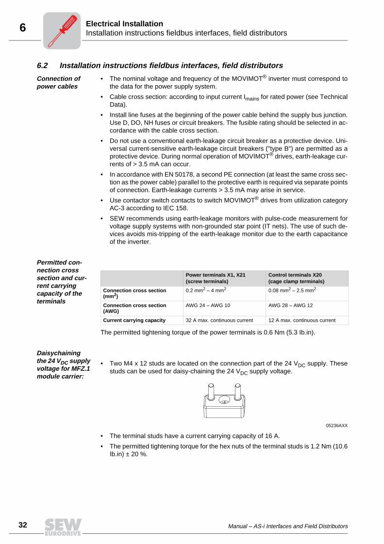
Daisychaining the 24 VDC supply voltage for MFZ.1 module carrier:
• Two M4 x 12 studs are located on the connection part of the 24 VDC supply. Thesestuds can be used for daisy-chaining the 24 VDC supply voltage.
• The terminal studs have a current carrying capacity of 16 A.
• The permitted tightening torque for the hex nuts of the terminal studs is 1.2 Nm (10.6Ib.in) ± 20 %.
Power terminals X1, X21(screw terminals)
Control terminals X20(cage clamp terminals)
Connection cross section (mm2)
0.2 mm2 – 4 mm2 0.08 mm2 – 2.5 mm2
Connection cross section (AWG)
AWG 24 – AWG 10 AWG 28 – AWG 12
Current carrying capacity 32 A max. continuous current 12 A max. continuous current
05236AXX
Manual – AS-i Interfaces and Field Distributors 33
6Installation instructions fieldbus interfaces, field distributorsElectrical Installation
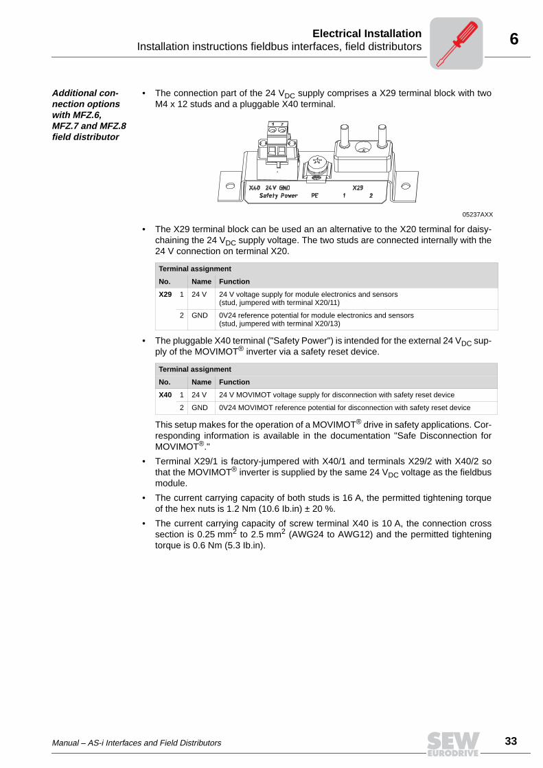
Additional con-nection options with MFZ.6, MFZ.7 and MFZ.8 field distributor
• The connection part of the 24 VDC supply comprises a X29 terminal block with twoM4 x 12 studs and a pluggable X40 terminal.
• The X29 terminal block can be used an an alternative to the X20 terminal for daisy-chaining the 24 VDC supply voltage. The two studs are connected internally with the24 V connection on terminal X20.
• The pluggable X40 terminal ("Safety Power") is intended for the external 24 VDC sup-ply of the MOVIMOT® inverter via a safety reset device.
This setup makes for the operation of a MOVIMOT® drive in safety applications. Cor-responding information is available in the documentation "Safe Disconnection forMOVIMOT®."
• Terminal X29/1 is factory-jumpered with X40/1 and terminals X29/2 with X40/2 sothat the MOVIMOT® inverter is supplied by the same 24 VDC voltage as the fieldbusmodule.
• The current carrying capacity of both studs is 16 A, the permitted tightening torqueof the hex nuts is 1.2 Nm (10.6 Ib.in) ± 20 %.
• The current carrying capacity of screw terminal X40 is 10 A, the connection crosssection is 0.25 mm2 to 2.5 mm2 (AWG24 to AWG12) and the permitted tighteningtorque is 0.6 Nm (5.3 Ib.in).
05237AXX
Terminal assignment
No. Name Function
X29 1 24 V 24 V voltage supply for module electronics and sensors(stud, jumpered with terminal X20/11)
2 GND 0V24 reference potential for module electronics and sensors(stud, jumpered with terminal X20/13)
Terminal assignment
No. Name Function
X40 1 24 V 24 V MOVIMOT voltage supply for disconnection with safety reset device
2 GND 0V24 MOVIMOT reference potential for disconnection with safety reset device

6
34 Manual – AS-i Interfaces and Field Distributors
Installation instructions fieldbus interfaces, field distributorsElectrical Installation
Installation at 1000 meters above sea level (msl)
MOVIMOT® drives with supply voltages of 380 to 500 V can be used at altitudes above2000 msl up to 4000 msl under the following peripheral conditions.
• The rated continuous power is reduced based on the reduced cooling above 1000 m(see the section MOVIMOT® Operating Instructions).
• At 2000 msl, the air and creeping distances are only sufficient for overvoltage class2. If the installation requires overvoltage class 3, an additional external overvoltageprotection must be used to ensure that overvoltage surges are limited to 2.5 kVphase-to-phase and phase-to-ground.
• If safe electrical separation is required, it must be implemented outside the device ataltitudes of 2000 msl (safe electrical separation in accordance with EN 50178).
• The permitted rated supply voltage of 3 x 500 V up to 2000 msl is reduced by 6 V forevery 100 m to a maximum of 3 x 380 V at 4000 msl.
Protective devices
• MOVIMOT® drives are equipped with integrated protective overload devices that aremaking external devices obsolete.
UL compliant field distributor installation
• Use only copper cables with the following temperature ranges as connection cables:Temperature range: 60 / 75 °C
• MOVIMOT® drives are suited for operation on voltage supply systems with groundedstar point (TN and TT systems) providing a maximum supply current of 5000 AAC andhaving a maximum rated voltage of 500 VAC (MM03C-503 to MM3XC-503). The per-formance data of the fuses must not exceed 35 A/600 V when operated with field dis-tributor.
• Use only tested units with limited output voltage (Umax = 30 VDC) and limited outputcurrent (I = 8 A) as external 24 VDC voltage supply source.
• UL certification applies only to operation in voltage supply systems with voltages toground up to 300 V.

Manual – AS-i Interfaces and Field Distributors 35
6Installation instructions fieldbus interfaces, field distributorsElectrical Installation
EMC metal cable glands
EMC metal cable glands supplied by SEW must be installed as follows:
[1] Important: Cut off insulation foil, but do not fold it back!
06175AXX
[1]

6
36 Manual – AS-i Interfaces and Field Distributors
Installation instructions fieldbus interfaces, field distributorsElectrical Installation
Wiring check Before connecting power to the system for the first time, it is necessary to perform a wir-ing check to prevent damage to persons, systems and equipment caused by incor-rect wiring.
• Disconnect all bus modules from the connection module
• Disconnect all MOVIMOT® inverters from the connection module (only with MFZ.7,MFZ.8)
• Disconnect all plug connectors of the motor outputs (hybrid cable) from the field dis-tributor.
• Check the insulation of the cabling in accordance with applicable national standards.
• Check the grounding.
• Check whether power cable and 24 VDC cable are insulated.
• Check whether power cable and communication cable are insulated.
• Check the polarity of the 24 VDC cable.
• Check the polarity of the communication cable.
• Check the mains phase sequence.
• Ensure equipotential bonding between the fieldbus interfaces.
After the wiring check
• Connect and fasten all motor outputs (hybrid cable).
• Connect and fasten all bus modules.
• Install and fasten all MOVIMOT® inverters (for MFZ.7, MFZ.8 only).
• Install all terminal box covers.
• Cover plug connections not in use.

Manual – AS-i Interfaces and Field Distributors 37
6AS-i cable connectionElectrical Installation
6.3 AS-i cable connection
The MFK.. AS-i interface must be connected with the AS-i network using the yellow AS-i cable. The connection is carried out using the AS-i M12 connector integrated in the cor-responding connection module (e.g. MFK../Z66./AF6 field distributor). In addition, theMFK AS-i interface must be supplied with 24 V auxiliary voltage.
AS-i and 24 V connection using yellow and black cable with dou-ble tap
AS-i connection with yellow cable, 24 V supply with circular conduc-tor
51316AXX
MFI A
S-In
terfa
ce AS-i PWR
AS-i FLT
AS-i PWR
SYS-F
AS-i (YE)
AUX-PWR (BK)
51316AXX
MFI A
S-Int
erfac
e AS-i PWR
AS-i FLT
AS-i PWR
SYS-F
24 V
AS-i (YE)
24 V
AS-i (YE)
Any additional connections (depending on the selected connection module) are de-scribed in the following sections.

6
38 Manual – AS-i Interfaces and Field Distributors
Connection with double tapElectrical Installation
6.4 Connection with double tap
Connection of module carrier MFZ61 with MOVIMOT®
05983AXX
0 = Potential level 0 1 = Potential level 1
[1] If MFZ61/MOVIMOT® are mounted separately:Connect the shield of the RS-485 cable using the EMC metal cable gland on the MFZ unit and the MOVIMOT®
housing[2] Ensure equipotential bonding between all bus stations.[3] Assignment of terminals 19-36 starting on page 44
1
19
2
20
3
21
4
22
5
23
6
24
7
25
8
26
9
27
10
28
11
29
12
30
13
31
14
32
15
33
16
34
17
35
18
36
24V
RS
+
RS
-
GN
D
0 1
MFZ61 (AS-i)
4
21
3
24V
R L f1/f2
K1a
K1b
RS
-R
S+
MOVIMOT®[3]
[2]
[1] [1]
X11
X20
+MFZ61A
MFK..
1234
AS-i +0V24 (AUX-PWR)AS-i -24V (AUX-PWR)
X11
Terminal assignment
No. Name Direction Function
X20 1 - - Reserved
2 AS-i - Input/output AS-i data line and electronics supply for MFK
3 - - Reserved
4 - - Reserved
5 AS-i + Input/output AS-i data line and electronics supply for MFK
6 - - Reserved
7 - - Reserved
8 - - Reserved
9 - - Reserved
10 - - Reserved
11 24 V (AUX-PWR) Input 24 V voltage supply for MOVIMOT®, sensors
12 24 V (AUX-PWR) Output 24 V voltage supply (jumpered with terminal X20/11)
13 GND (AUX-PWR) - 0V24 reference potential for MOVIMOT® and sensors
14 GND (AUX-PWR) - 0V24 reference potential for MOVIMOT® and sensors
15 24 V - 24 V voltage supply for MOVIMOT® (jumpered with terminal X20/11)
16 RS+ - Communication link to MOVIMOT® terminal RS+
17 RS- - Communication link to MOVIMOT® terminal RS-
18 GND - 0V24 reference potential for MOVIMOT® (jumpered with X20/13)

Manual – AS-i Interfaces and Field Distributors 39
6Connection with double tapElectrical Installation
Connection of MFZ63 field distributor
05984AXX
0 = Potential level 0 1 = Potential level 1 2 = Potential level 2
8 7 6 5 4 3 2 1
L3
L2
L1
PE
L3
L2
L1
PE
4 mm (AWG10)2X1
1 2 3 4 5 6 7 8 9 10 1 2 3 4 5 6 7 8
PE L1
L1
L2
L2 L3
L3
PE
4 mm (AWG10)2.5 mm (AWG12)
0 1 2
2 2
X20 X21
+MFK21
MFK22MFZ63
4
21
3X11 1
234
AS-i +0V24 (AUX-PWR)AS-i -24V (AUX-PWR)
X11
Terminal assignment
No. Name Direction Function
X20 1 - - Reserved
2 AS-i - Input/output AS-i data line and electronics supply for MFK
3 - - Reserved
4 - - Reserved
5 AS-i + Input/output AS-i data line and electronics supply for MFK
6-10
- - Reserved
X21 1 24 V (AUX-PWR) Input 24 V voltage supply for MOVIMOT® and sensors
2 24 V (AUX-PWR) Output 24 V voltage supply (jumpered with terminal X21/1)
3 GND (AUX-PWR) - 0V24 reference potential for sensors and MOVIMOT®
4 GND (AUX-PWR) - 0V24 reference potential for sensors and MOVIMOT®
5 V2I24 Input 24 V voltage supply for actuators (digital outputs)
6 V2I24 Output 24 V voltage supply for actuators (digital outputs)jumpered with terminal X21/5
7 GND2 - 0V24V reference potential for actuators
8 GND2 - 0V24V reference potential for actuators
6
40 Manual – AS-i Interfaces and Field Distributors
Connection with double tapElectrical Installation
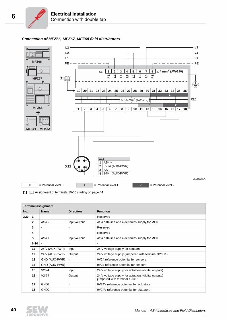
Connection of MFZ66, MFZ67, MFZ68 field distributors
05985AXX
0 = Potential level 0 1 = Potential level 1 2 = Potential level 2
[1] Assignment of terminals 19-36 starting on page 44
1
19
2
20
3
21
4
22
5
23
6
24
7
25
8
26
9
27
10
28
11
29
12
30
13
31
14
32
15
33
16
34
17
35
18
36
1 2 3 4 5 6 7 8
PE L1
L1
L2
L2
L3
L3
PE
L3
L2
L1
PE
L3
L2
L1
PE
4 mm (AWG10)2X1
0 1 2
1 2
2.5 mm (AWG12)2 X20
+
MFZ66
MFZ67
MFZ68
MFK21 MFK22
4
21
3
X11
[1]
1234
AS-i +0V24 (AUX-PWR)AS-i -24V (AUX-PWR)
X11
Terminal assignment
No. Name Direction Function
X20 1 - - Reserved
2 AS-i - Input/output AS-i data line and electronics supply for MFK
3 - - Reserved
4 - - Reserved
5 AS-i + Input/output AS-i data line and electronics supply for MFK
6-10 - - -
11 24 V (AUX-PWR) Input 24 V voltage supply for sensors
12 24 V (AUX-PWR) Output 24 V voltage supply (jumpered with terminal X20/11)
13 GND (AUX-PWR) - 0V24 reference potential for sensors
14 GND (AUX-PWR) - 0V24 reference potential for sensors
15 V2I24 Input 24 V voltage supply for actuators (digital outputs)
16 V2I24 Output 24 V voltage supply for actuators (digital outputs)jumpered with terminal X20/15
17 GND2 - 0V24V reference potential for actuators
18 GND2 - 0V24V reference potential for actuators

Manual – AS-i Interfaces and Field Distributors 41
6Connection with single tap and 24 V loopElectrical Installation
6.5 Connection with single tap and 24 V loop
Connection of MFZ61 module carrier with MOVIMOT®
06161AXX
0 = Potential level 0 1 = Potential level 1
[1] If MFZ61/MOVIMOT® are mounted separately:Connect the shield of the RS-485 cable using the EMC metal cable gland on the MFZ unit and the MOVIMOT®
housing[2] Ensure equipotential bonding between all bus stations.[3] Assignment of terminals 19-36 starting on page 44[4] Cables must be rewired at the customer
1
19
2
20
3
21
4
22
5
23
6
24
7
25
8
26
9
27
10
28
11
29
12
30
13
31
14
32
15
33
16
34
17
35
18
36
24V
RS
+
RS
-
GN
D
0 1
MFZ61 (AS-i)
4
21
3
24V
R L f1/f2
K1a
K1b
RS
-R
S+
MOVIMOT®[3]
[2]
[1] [1]
X11
X20
+MFZ61A
MFK..
24 VDC
+ -[4]
[4]
1234
AS-i +0V24 (AUX-PWR)AS-i -24V (AUX-PWR)
X11
Terminal assignment
No. Name Direction Function
X20 1 - - Reserved
2 AS-i - Input/output AS-i data line and electronics supply for MFK
3 - - Reserved
4 - - Reserved
5 AS-i + Input/output AS-i data line and electronics supply for MFK
6 - - Reserved
7 - - Reserved
8 - - Reserved
9 - - Reserved
10 - - Reserved
11 24 V (AUX-PWR) Input 24 V voltage supply for MOVIMOT®, sensors
12 24 V (AUX-PWR) Output 24 V power supply (jumpered with terminal X20/11)
13 GND (AUX-PWR) - 0V24 reference potential for MOVIMOT® and sensors
14 GND (AUX-PWR) - 0V24 reference potential for MOVIMOT® and sensors
15 24 V - 24 V voltage supply for MOVIMOT® (jumpered with terminal X20/11)
16 RS+ - Communication link to MOVIMOT® terminal RS+
17 RS- - Communication link to MOVIMOT® terminal RS-
18 GND - 0V24 reference potential for MOVIMOT® (jumpered with X20/13)

6
42 Manual – AS-i Interfaces and Field Distributors
Connection with single tap and 24 V loopElectrical Installation
Connection of MFZ63 field distributor
06162AXX
[1] Cables must be rewired at the customer site[2] Factory jumpers 0.75 mm2
0 = Potential level 0 1 = Potential level 1 2 = Potential level 2
8 7 6 5 4 3 2 1
L3
L2
L1
PE
L3
L2
L1
PE
4 mm (AWG10)2X1
1 2 3 4 5 6 7 8 9 10 1 2 3 4 5 6 7 8
PE L1
L1
L2
L2 L3
L3
PE
4 mm (AWG10)2.5 mm (AWG12)
0 1 2
2 2
X20 X21
+MFK21
MFK22MFZ63
4
21
3X11
24V
GND
24V
GND
[1]
[1]
[2]
[2]
1234
AS-i +0V24 (AUX-PWR)AS-i -24V (AUX-PWR)
X11
Terminal assignment
No. Name Direction Function
X20 1 - - Reserved
2 AS-i - Input/output AS-i data line and electronics supply for MFK
3 - - Reserved
4 - - Reserved
5 AS-i + Input/output AS-i data line and electronics supply for MFK
6-10
- - Reserved
X21 1 24 V (AUX-PWR) Input 24 V voltage supply for MOVIMOT® and sensors
2 24 V (AUX-PWR) Output 24 V voltage supply (jumpered with terminal X21/1)
3 GND (AUX-PWR) - 0V24 reference potential for sensors and MOVIMOT®
4 GND (AUX-PWR) - 0V24 reference potential for sensors and MOVIMOT®
5 V2I24 Input 24 V voltage supply for actuators (digital outputs)
6 V2I24 Output 24 V voltage supply for actuators (digital outputs)jumpered with terminal X21/5
7 GND2 - 0V24V reference potential for actuators
8 GND2 - 0V24V reference potential for actuators

Manual – AS-i Interfaces and Field Distributors 43
6Connection with single tap and 24 V loopElectrical Installation
Connection of MFZ66, MFZ67, MFZ68 field distributors
06163AXX
0 = Potential level 0 1 = Potential level 1 2 = Potential level 2
[1] Assignment of terminals 19-36 starting on page 44[2] Cables must be rewired at the customer site[3] Factory jumpers 0.75 mm2
1
19
2
20
3
21
4
22
5
23
6
24
7
25
8
26
9
27
10
28
11
29
12
30
13
31
14
32
15
33
16
34
17
35
18
36
1 2 3 4 5 6 7 8
PE L1
L1
L2
L2
L3
L3
PE
L3
L2
L1
PE
L3
L2
L1
PE
4 mm (AWG10)2X1
0 1 2
1 2
2.5 mm (AWG12)2 X20
+
MFZ66
MFZ67
MFZ68
MFK21 MFK22
4
21
3
X11
24V
GND
24V
GND
[2]
[2]
[3]
[3]
[1]
1234
AS-i +0V24 (AUX-PWR)AS-i -24V (AUX-PWR)
X11
Terminal assignment
No. Name Direction Function
X20 1 - - Reserved
2 AS-i - Input/output AS-i data line and electronics supply for MFK
3 - - Reserved
4 - - Reserved
5 AS-i + Input/output AS-i data line and electronics supply for MFK
6-10 - - -
11 24 V (AUX-PWR) Input 24 V voltage supply for sensors
12 24 V (AUX-PWR) Output 24 V voltage supply (jumpered with terminal X20/11)
13 GND (AUX-PWR) - 0V24 reference potential for sensors
14 GND (AUX-PWR) - 0V24 reference potential for sensors
15 V2I24 Input 24 V voltage supply for actuators (digital outputs)
16 V2I24 Output 24 V voltage supply for actuators (digital outputs)jumpered with terminal X20/15
17 GND2 - 0V24V reference potential for actuators
18 GND2 - 0V24V reference potential for actuators

6
44 Manual – AS-i Interfaces and Field Distributors
Connection of inputs / outputs (I/O) of MFK.. AS-i interfacesElectrical Installation
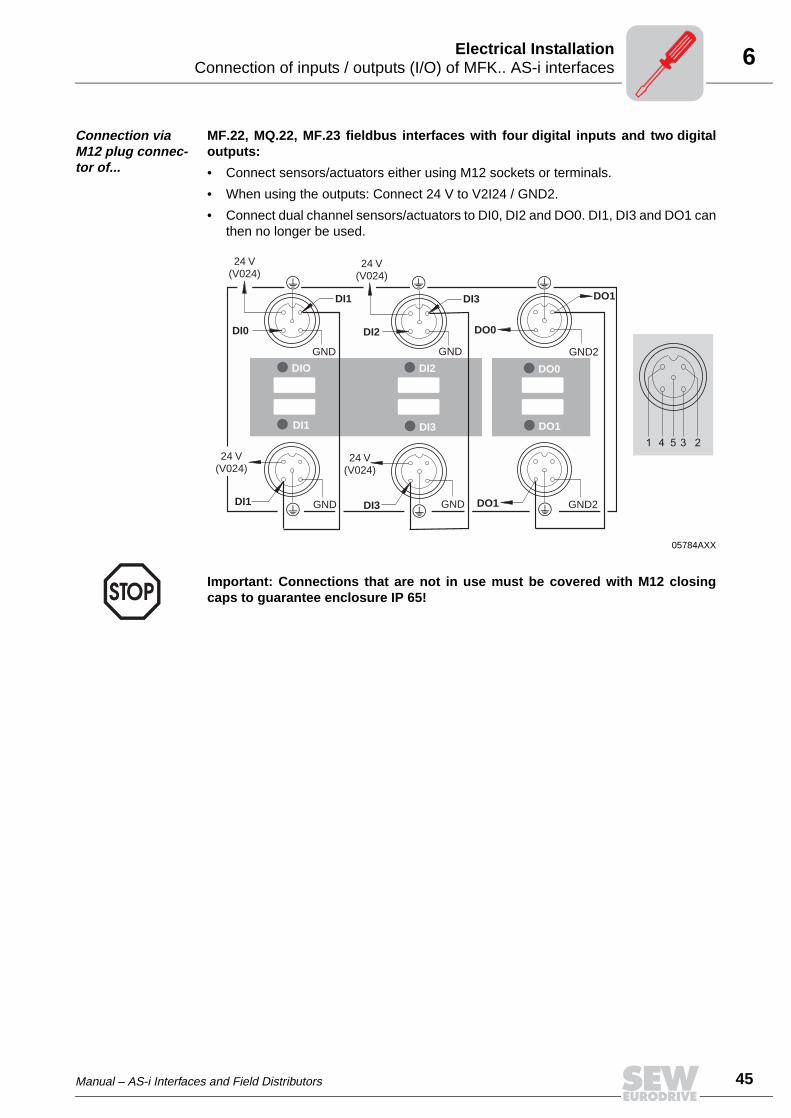
6.6 Connection of inputs / outputs (I/O) of MFK.. AS-i interfaces
Connection via terminals of..
fieldbus interfaces with four digital inputs and two digital outputs:
MFZ.1MFZ.6MFZ.7MFZ.8
in combination withMF.21MF.22MF.23
MQ.21MQ.22
06122AXX
[1] MFI23 only: Reservedall other MF.. modules: V2I24
1 = Potential level 1
2 = Potential level 2
No. Name Direction Function
X20 19 DI0 Input Switching signal from sensor 1
20 GND - 0V24 reference potential for sensor 1
21 V024 Output 24 V voltage supply for sensor 1
22 DI1 Input Switching signal from sensor 2
23 GND - 0V24 reference potential for sensor 2
24 V024 Output 24 V voltage supply for sensor 2
25 DI2 Input Switching signal from sensor 3
26 GND - 0V24 reference potential for sensor 3
27 V024 Output 24 V voltage supply for sensor 3
28 DI3 Input Switching signal from sensor 4
29 GND - 0V24 reference potential for sensor 4
30 V024 Output 24 V voltage supply for sensor 4
31 DO0 Output Switching signal from actuator 1
32 GND2 - 0V24 reference potential for actuator 1
33 DO1 Output Switching signal from actuator 2
34 GND2 - 0V24 reference potential for actuator 2
35 V2I24 Input24 V voltage supply for actuatorsonly with MFI23: Reservedonly with MFZ.6, MFZ.7 and MFZ.8: jumper at terminal 15 or 16
36 GND2 - 0V24 reference potential for actuatorsonly with MFZ.6, MFZ.7 and MFZ.8: jumper at terminal 17 or 18
19 20 21 22 23 24 25 26 27 28 29 30 31 32 33 34 35 36
DI 0
GN
D
VO
24
DI 1
GN
D
VO
24
DI 2
GN
D
VO
24
DI 3
GN
D
VO
24
DO
0
GN
D2
DO
1
GN
D2
GN
D2
1 2X20
V2I
24[1
]
Manual – AS-i Interfaces and Field Distributors 45
6Connection of inputs / outputs (I/O) of MFK.. AS-i interfacesElectrical Installation
Connection via M12 plug connec-tor of...
MF.22, MQ.22, MF.23 fieldbus interfaces with four digital inputs and two digitaloutputs:
• Connect sensors/actuators either using M12 sockets or terminals.
• When using the outputs: Connect 24 V to V2I24 / GND2.
• Connect dual channel sensors/actuators to DI0, DI2 and DO0. DI1, DI3 and DO1 canthen no longer be used.
05784AXX
DIO DI2 DO0
DI3 DO1DI1
24 V(V024)
24 V(V024)
GND GND GND2
GND GND GND2
DI1 DI3 DO1
24 V(V024)
24 V(V024)
DI2 DO0
DI3 DO1
DI0
DI1
1 4 5 3 2
Important: Connections that are not in use must be covered with M12 closingcaps to guarantee enclosure IP 65!

6
46 Manual – AS-i Interfaces and Field Distributors
Connection of pre-fabricated cablesElectrical Installation
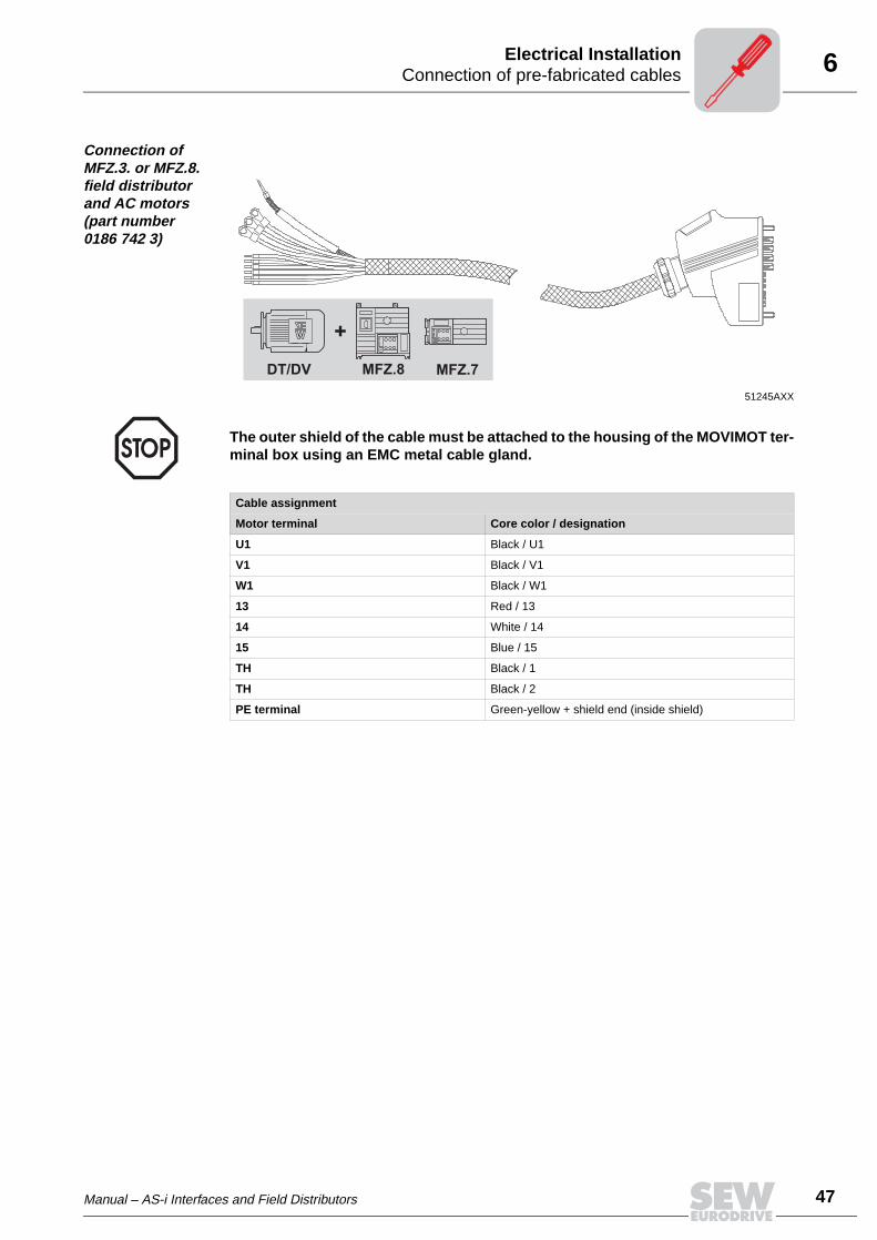
6.7 Connection of pre-fabricated cables
Connection of MFZ.3. or MFZ.6. field distributor and MOVIMOT® (part number 0186 725 3)
Note the enabled direction of rotation
51246AXX
DT/DV..MM MFZ.6
+
MFZ.3
The outer shield of the cable must be attached to the housing of the MOVIMOT®
terminal box using an EMC metal cable gland.
Cable assignment
MOVIMOT® terminal Core color / designation
L1 Black / L1
L2 Black / L2
L3 Black / L3
24 V Red / 24 V
⊥ White / 0 V, white / 0 V
RS+ Orange / RS+
RS- Green / RS-
PE terminal Green-yellow + shield end
Both directions of rotation are enabled
Only counterclockwise direction of rota-tion is enabledSetpoint entries for clockwise rotation result in standstill of drive
Only clockwise direction of rotation is enabledSetpoint selections for counterclock-wise lead to the drive being stopped
Drive is blocked or brought to a stop
24V
LR LR24V
LR24V
LR24V
Manual – AS-i Interfaces and Field Distributors 47
6Connection of pre-fabricated cablesElectrical Installation
Connection of MFZ.3. or MFZ.8. field distributor and AC motors (part number 0186 742 3)
51245AXX
DT/DV MFZ.7
+
MFZ.8
The outer shield of the cable must be attached to the housing of the MOVIMOT ter-minal box using an EMC metal cable gland.
Cable assignment
Motor terminal Core color / designation
U1 Black / U1
V1 Black / V1
W1 Black / W1
13 Red / 13
14 White / 14
15 Blue / 15
TH Black / 1
TH Black / 2
PE terminal Green-yellow + shield end (inside shield)

7
48 Manual – AS-i Interfaces and Field Distributors
Startup procedureStartup
7 Startup7.1 Startup procedure
1. Verify correct connection of MOVIMOT® and AS-i connection module (MFZ61,MFZ63, MFZ66, MFZ67 or MFZ68).
2. Set DIP switch S1/1 (on MOVIMOT®) to ON (= address 1).
3. Set the maximum speed using f1 setpoint potentiometer (on MOVIMOT®).
4. Re-insert screw plug of the cover (with gasket).
5. Set minimum frequency fmin with switch f2 (on MOVIMOT®).
6. Depending upon the selected function module, set the ramp time with switch t1 (onMOVIMOT®) (not important for function module 1). The ramp times are in relation toa setpoint step change of 50 Hz.
• We recommend switching off all voltage supplies before removing/attaching the AS-i interface (MFK)!
• The AS-i connection is permanently secured using the connection technology de-scribed on page 37 so that the AS-i network operation can continue even after re-moval of the interface.
• Observe the notes in the chapter "Supplemental Field Distributor Startup Informa-tion."
05064AXX
05066BXX
[1] Potentiometer setting
Function Setting
Detent position 0 1 2 3 4 5 6 7 8 9 10
Minimum frequency fmin [Hz]
2 5 7 10 12 15 20 25 30 35 40
Function Setting
Detent position 0 1 2 3 4 5 6 7 8 9 10
Ramp time t1 [s] 0,1 0,3 0,2 0,5 0,7 1 2 3 5 7 10
1
ON
S1
6 7 854321
ON
S1
32
1 2 3 4 5 6 7 8 9 100
100f [Hz
[1]
]
2
75
25
50
65f1
34
56
78
34
56
78

Manual – AS-i Interfaces and Field Distributors 49
7Assignment of AS-i address via an addressing deviceStartup
7. The assignment of the required AS-i address is carried out either via addressing de-vice (see the following section) or later via a master (see the description of your AS-i master).
8. Switch on AS-i voltage and 24 V auxiliary voltage. The LEDs AS-i PWR LED andAUX-PWR LED will illuminate in green and the SYS-F-LED must go out.
7.2 Assignment of AS-i address via an addressing device
An AS-i addressing device can be used to assign the address. This allows simple andnetwork-independent addressing.
The AS-i addressing devices offer the following functions:
• Reading an AS-i address
• Incremental adjustment of address to new value
• Readdressing of AS-i interfaces
• Functional test with output to display
The use of an addressing device requires a connection cable that fits onto the M12 plugconnector of the MFK connection module (see the following figure).
Example: Every AS-i station is individually addressed (A) and then reintegrated in thebus (B).
06109AXX
[1] Pin 2 + 4 are not required for address assignment
51318AXX
[1] AS-i addressing device
4
21
31:2:3:4:
AS-i +0V24 [1]AS-i -24V [1]
X11
A B
[1]
MFK../Z66.MFK../Z66.
00
I
8
50 Manual – AS-i Interfaces and Field Distributors
Overview of function modulesFunction of the MFK.. AS-i Interface
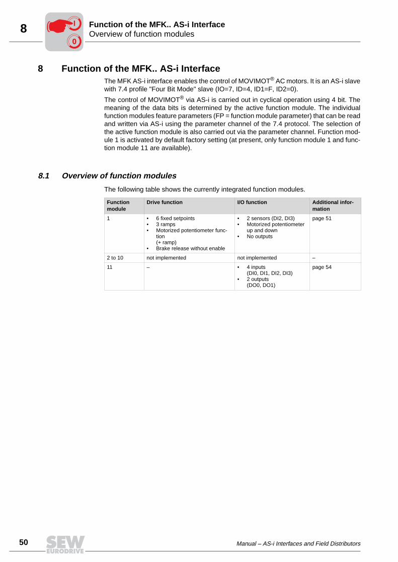
8 Function of the MFK.. AS-i InterfaceThe MFK AS-i interface enables the control of MOVIMOT® AC motors. It is an AS-i slavewith 7.4 profile "Four Bit Mode" slave (IO=7, ID=4, ID1=F, ID2=0).
The control of MOVIMOT® via AS-i is carried out in cyclical operation using 4 bit. Themeaning of the data bits is determined by the active function module. The individualfunction modules feature parameters (FP = function module parameter) that can be readand written via AS-i using the parameter channel of the 7.4 protocol. The selection ofthe active function module is also carried out via the parameter channel. Function mod-ule 1 is activated by default factory setting (at present, only function module 1 and func-tion module 11 are available).
8.1 Overview of function modules
The following table shows the currently integrated function modules.
Function module
Drive function I/O function Additional infor-mation
1 • 6 fixed setpoints• 3 ramps• Motorized potentiometer func-
tion (+ ramp)
• Brake release without enable
• 2 sensors (DI2, DI3)• Motorized potentiometer
up and down• No outputs
page 51
2 to 10 not implemented not implemented –
11 – • 4 inputs(DI0, DI1, DI2, DI3)
• 2 outputs(DO0, DO1)
page 54
00
I

Manual – AS-i Interfaces and Field Distributors 51
8Description of function modulesFunction of the MFK.. AS-i Interface
8.2 Description of function modules
Function module 1
The following section describes the cyclical data exchange between master and slave.
Data transfer mas-ter → slave
The following table describes the data transfer from master to slave:
Data transfer slave → master
The following table describes the data transfer from slave to master:
4-bit coded Message
0000bin = 0dec Rapid stop/Blocking
0001bin = 1dec Stop/Blocking (uses ramp down)
0010bin = 2dec Enable + setpoint n11
0011bin = 3dec Enable + setpoint n12
0100bin = 4dec Enable + setpoint n13
0101bin = 5dec Enable + setpoint n21
0110bin = 6dec Enable + setpoint n22
0111bin = 7dec Enable + setpoint n23
1000bin = 8dec Motorized potentiometer: Enable CW running
1001bin = 9dec Motorized potentiometer: Enable CCW running
1010bin = 10dec Reserved
1011bin = 11dec Reserved
1100bin = 12dec Reserved
1101bin = 13dec Reserved
1110bin = 14dec Brake release without enablewith activated MOVIMOT® DIP switch S2/2 (additional information can be found in the MOVIMOT® Operat-ing Instructions)
1111bin = 15dec Reset (only effective with MOVIMOT® fault)
4-bit coded (single) Message
Bit 0 Ready message
Bit 1 Enabled
Bit 2 Digital input DI2
Bit 3 Digital input DI3
00
I

8
52 Manual – AS-i Interfaces and Field Distributors
Description of function modulesFunction of the MFK.. AS-i Interface
Parameter func-tion module 1
The following table describes the parameters for function module 1:
Function of motor potentiometer
The motor potentiometer function is used for continuous speed control: The ramp timesrefer to a setpoint change of ∆f = 50 Hz.
Ramp up/ramp down → index 41dec
• Setting range: 0,2 ... 20 ... 50 s
• After 24 V OFF and 24 V ON or after removal of enable, the drive starts with nmin(fmin).
• The ramp is active if the drive is enabled with motorized potentiometer function (AS-i code "8" or "9") and one of the two corresponding input terminals (DI0 or DI1) fea-tures a "1" signal.
Index Access type Type Default Message
20hex 32dec read/write INT16 5% = 0333hex Setpoint n11
21hex 33dec read/write INT16 25% = 1000hex Setpoint n12
22hex 34dec read/write INT16 50% = 2000hex Setpoint n13
23hex 35dec read/write INT16 -5% = FCCDhex Setpoint n21
24hex 36dec read/write INT16 -25% = F000hex Setpoint n22
25hex 37dec read/write INT16 -50% = E000hex Setpoint n23
26hex 38dec read/write UINT16 1000 Ramp up [ms]
27hex 39dec read/write UINT16 1000 Ramp down [ms]
28hex 40dec read/write UINT16 100 Rapid stop ramp [ms]
29hex 41dec read/write UINT16 20000 Motor potentiometer ramp [ms]
2Ahex 42dec read UINT16 0 State
2Bhex 43dec read UINT16 0 Error no. identical to diagnostics string
51402AXX
[1] AS-i = "8" or "9"
nmin
nmax
"0"
"0"
"0"
"1"
"1"
"1"
n
t
t
t
t
[1]
DI0
DI1
00
I

Manual – AS-i Interfaces and Field Distributors 53
8Description of function modulesFunction of the MFK.. AS-i Interface
MOVIMOT® spe-cial functions in connection with function module 1
The following table must be observed when using the MOVIMOT® special functions. Adetailed description of the special functions can be found in the "MOVIMOT®
MM03C–MM3XC" Operating Instructions.
Special function Limitations with MOVIMOT® integrated in the motor
Limitations with MOVIMOT® integrated in Z.7 and Z.8 field distributor
1 MOVIMOT® with increased ramp times – –
2 MOVIMOT® with adjustable current limita-tion (fault if exceeded)
– –
3 MOVIMOT® with adjustable current limita-tion (switchable via terminal f1/f2)
– –
4 MOVIMOT® with bus parameter setting not possible not possible
5 MOVIMOT® with motor protection in Z.7 and Z.8 field distributor
not possible –
6 MOVIMOT® with maximum 8 kHz PWM frequency
– –
7 MOVIMOT® with rapid start/stop Rapid stop function (bit 9) not possible Rapid stop function (bit 9) not possible
The mechanical brake must only be con-trolled by MOVIMOT®. Controlling the brake via relay output is not possible.
8 MOVIMOT® with minimum frequency 0 Hz Not possible when motor potentiometer function is used
Not possible when motor potentiometer function is used
9 MOVIMOT® for hoist applications Rapid stop function (bit 9) not possible not possible
10 MOVIMOT® with minimum frequency 0 Hz and reduced torque at low frequencies
Not possible when motor potentiometer function is used
Not possible when motor potentiometer function is used
11 Monitoring of supply phase fault is deacti-vated
– –
12 MOVIMOT® with quick start/stop and motor protection in Z.7 and Z.8 field distrib-utors
not possible –
00
I

8
54 Manual – AS-i Interfaces and Field Distributors
Description of function modulesFunction of the MFK.. AS-i Interface
Function module 11
The following section describes the cyclical data exchange between master and slavewith activated function module 11.
Data transfer mas-ter → slave
The following table describes the data transfer from master to slave:
Data transfer slave → master
The following table describes the data transfer from slave to master:
4-bit coded Message
Bit 0 Digital output DO0
Bit 1 Digital output DO1
Bit 2 –
Bit 3 –
4-bit coded Message
Bit 0 Digital input DI0
Bit 1 Digital input DI1
Bit 2 Digital input DI2
Bit 3 Digital input DI3
No parameters are assigned to function module 11.
00
I

Manual – AS-i Interfaces and Field Distributors 55
8Index assignment of the function modulesFunction of the MFK.. AS-i Interface
8.3 Index assignment of the function modules
The parameters of the function modules are each 16-bit values. Dependent upon the pa-rameter, they are interpreted with or without sign.
The description of the function modules starts on page 51.
8.4 Parameter transfer notes
MOVIMOT® can be operated during the transfer of parameters/diagnostics strings. If thetransfer takes more than 1 second, the MOVIMOT® drive is stopped via PO1.
Index 0 is used for switching over the active function module and can only be written toif the MOVIMOT® drive is not enabled. If the MOVIMOT® drive is enabled while writingindex 0, the value is not accepted (no fault message is created).
Index Message Access Default value
0dec Active function module Read/write only if MOVIMOT® is not enabled
1
1dec to 31dec Reserved read/write 0
32dec to 63dec Parameter function module 1
64dec to 383dec Reserved
• Important: If parameter data are continuously exchanged between controllerand MFK in rapid succession, the cyclical (binary) data transfer is preventedunder certain conditions (with few AS-i slaves)! This is an AS-i system behav-ior and cannot be influeneced by the unit manufacturer.
• Particularly in operation with function module 1, this behavior prevents con-trolling or switching off the MOVIMOT® drive!
• Remedy: Prevent cyclical exchange of parameter data!
00
I

8
56 Manual – AS-i Interfaces and Field Distributors
Write parameter stringFunction of the MFK.. AS-i Interface
8.5 Write parameter string
When writing parameters, the first two bytes are interpreted as start index.
The following bytes (max. 64) are the data written in the subsequent indexes. The firstbyte is the more significant byte. The number of bytes being transferred must always beeven.
If only two bytes are written, only the index for the next read command is set. No param-eters are changed.
Example Setting the speed values n11 to n23 in function module 11:
The calculation of the speeds can be found in the section "MOVILINK® Unit Profile"
8.6 Read parameter string
The two bytes of the parameter written last are always read. Each reading process in-creases the index by 1. If no reading or writing has taken place since switch-on, then theindex is set to 0.
To read a specific index, a 2-byte write command must be issued that sets the index forthe next read command.
When reading a parameter, the first two bytes designate the index. The following bytesrepresent the content (date) of the index read. The first byte is the more significant byte.
06110AXX
[1] Start index (example: Index 32dec = 20hex)[2] Parameter data (max. 64 bytes)[3] Data for parameter "Start index"[4] Data for parameter "Start index + 1"[5] Data for parameter "Start index + 2"[6] Data for parameter "Start index + 31"
Byte 1
0 20 0
2 3 4 5 6 7 8 65 66
[1] [2]
[3] [4] [5] [6]
1 2 3 4 5 6 7 8 9 10 11 12 13 14
0 0 2 0 0 6 6 7 1 9 0 0 2 6 6 C 3 0 0 7 3 9 A 2 E 0 0 0
Start index 10 % 40 % 60 % 75 % 90 % - 50 %
Index 21 Index 22 Index 23 Index 24 Index 25 Index 26
06112AXX
[1] Index to be read (Example: Index 33dec 21hex)[2] Date from index (Example: n12 = 1000hex = 25 %)
Byte 1
0 2 1 00 1 0 0
2
[1]
3 4
[2]
00
I

Manual – AS-i Interfaces and Field Distributors 57
8Read diagnosticsFunction of the MFK.. AS-i Interface
8.7 Read diagnostics
Use the diagnostics string to read out the current process data of the MOVILINK® profilevia the AS-i.
Structure of the 16-byte long diag-nosis string
Communication error
In case of a communications error to MOVIMOT®, PI1 is set to 5B20hex. In addition tothe PI1 status, the status message can issue the following error codes:
• EEPROM error: 19 20hex – 25dec 32dec → Inverter is blocked
• Short circuit output: 53 20hex – 83dec 32dec
06111AXX
PO = Process output dataPI = Process input data[1] = Version[2] = Status message
Communication to MOVIMOT® OK = PI1Communication to MOVIMOT® faulted = 5B20hex (system fault)
If no data exchange has taken place with MOVIMOT®, then:• PO1 = 0• PO2 = 0• PO3 = 0• PI1 = 0020hex• PI2 = 0000hex• PI3 = 0020hex
Byte 1
[1] [2] PO1 PO2 PO3 PI1 PI2 PI3
74 102 85 113 96 12 13 14 15 16
2 0 0 0 0 0 0 01 0 0 0 6 0 0 07 2 0 0 0 2 0 EC 6 0 0 4 6 0 6
00
I

8
58 Manual – AS-i Interfaces and Field Distributors
MFK system fault / MOVIMOT® faultFunction of the MFK.. AS-i Interface
8.8 MFK system fault / MOVIMOT® fault
The communication link between MFK and MOVIMOT® is interrupted if the MFK signalsa system fault ("SYS-FAULT" LED continuously lit). This system fault is signalled to thecontroller as fault code 91 dec via the diagnostics channel and via the status words ofthe process input data. Since this system fault generally calls attention to cablingproblems or a missing 24 V supply of the MOVIMOT® inverter, a RESET via controlword is not possible! As soon as the communications link is reestablished, thefault automatically resets itself. Check the electrical connection of MFK and MOVIM-OT®. In the event of a system fault, the process input data return a fixed bit pattern be-cause valid MOVIMOT® status information is no longer available. Only status word bit 5(malfunction) and the error code remain for evaluation within the controller. No other in-formation is valid!
The input information of the digital inputs is still updated and can still be evaluated withinthe controller (if implemented in the function module).
Process input word Hex value Message
PI1: Status word 1 5B20hex Fault code 91 (5Bhex), bit 5 (malfunction) = 1 No other status information is valid!
PI2: Current actual value 0000hex Information is not valid!
PI3: Status word 2 0020hex Bit 5 (malfunction) = 1 No other status information is valid!
Input byte of the digital inputs XXhex The input information of the digital inputs continues to be updated!
00
I

Manual – AS-i Interfaces and Field Distributors 59
8Meaning of the LED displayFunction of the MFK.. AS-i Interface
8.9 Meaning of the LED display
The MFK AS-i interface has four diagnostics LEDs:
• AS-i PWR LED
• AS-i FLT LED
• AUX PWR LED
• SYS-F LED
"AS-i PWR" LED
"AS-i FLT" LED
"AUX PWR" LED
51260AXX
MF
K
AS
-Int
erfa
ceM
FK
A
S-I
nter
face
SYS-FSYS-F
AUX PWRAUX PWR
AS-i FLTAS-i FLT
AS-i PWRAS-i PWR
LED Message Error rectification
Green AS-i supply OK –
Off AS-i supply missing Check connection of AS-i line
LED Message Error rectification
Off AS-i communication OK –
Red No AS-i data exchange (if no AS-i data exchange takes place for more than 50 ms, the LED is lit and the MOVIMOT® drive is blocked (PO1=0000hex)
• Check connection of AS-i master• Check project planning in AS-i master
LED Message Error rectification
Green 24 V auxiliary voltage OK –
Off No 24 V auxiliary voltage Check connection of 24 VDC auxiliary voltage
00
I
8
60 Manual – AS-i Interfaces and Field Distributors
Meaning of the LED displayFunction of the MFK.. AS-i Interface
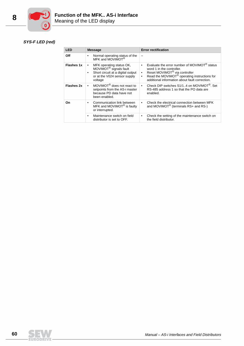
SYS-F LED (red)
LED Message Error rectification
Off • Normal operating status of the MFK and MOVIMOT®
–
Flashes 1x • MFK operating status OK, MOVIMOT® signals fault
• Short circuit at a digital output or at the V024 sensor supply voltage
• Evaluate the error number of MOVIMOT® status word 1 in the controller.
• Reset MOVIMOT® via controller• Read the MOVIMOT® operating instructions for
additional information about fault correction.
Flashes 2x • MOVIMOT® does not react to setpoints from the AS-i master because PD data have not been enabled.
• Check DIP switches S1/1..4 on MOVIMOT®. Set RS-485 address 1 so that the PO data are enabled.
On • Communication link between MFK and MOVIMOT® is faulty or interrupted.
• Check the electrical connection between MFK and MOVIMOT® (terminals RS+ and RS-)
• Maintenance switch on field distributor is set to OFF.
• Check the setting of the maintenance switch on the field distributor.
00
I

Manual – AS-i Interfaces and Field Distributors 61
9Field distributor MF.../Z.6., MQ.../Z.6.Supplemental Field Distributor Startup Information
9 Supplemental Field Distributor Startup InformationStartup is carried out according to the section "Startup with AS-i." In addition, note thefollowing information on the startup of field distributors.
9.1 Field distributor MF.../Z.6., MQ.../Z.6.
Maintenance switch
The maintenance/line protection switch of the Z.6. field distributor protects the hybridline against overload and switches the
– Power supply of the MOVIMOT®
– 24 VDC supply of the MOVIMOT®
Block diagram:
Important: The maintenance/line protection switch disconnects only theMOVIMOT® motor from the power supply system, not the field distributor.
05976AXX
[1] Jumper to supply of MOVIMOT® from 24 VDC voltage for MF../MQ.. fieldbus module(wired at factory)
[2] Connection of hybrid cable
[1]
"Safety Power"
RS-485
X1 X20 / X29
MF.. / MQ..
X40
L1
L2
L3
24V
GN
D
24V
GN
D
RS
+
RS
-
X9 [2]MFZ.6F
X40 X29 X20
00
I

9
62 Manual – AS-i Interfaces and Field Distributors
Field distributors MF.../MM../Z.7., MQ.../MM../Z.7.Supplemental Field Distributor Startup Information
9.2 Field distributors MF.../MM../Z.7., MQ.../MM../Z.7.
Checking the method of con-nection for the connected motor
Use the following figure to verify that the selected connection method is identical for thefield distributor and the connected motor.
Important: For brake motors: Do not install brake rectifiers inside the terminal boxof the motor!
Internal wiring of the MOVIMOT® inverter in the field distributor
03636AXX
U1 V1 W1
W2 U2 V2
U1 V1 W1
W2 U2 V2
05986AXX
[1] DIP switch for setting the method of connectionMake sure that the connection method of the connected motor matches the setting of the DIP switch.
[2] Note the released direction of rotation (default enables both directions of rotation)
Both directions of rotation are enabled
Only direction of rotationCCW is enabled
Only direction of rotationCW is enabled
04957AXX
[3] Standard integrated braking resistor (only in motors without brake)
24
V
TH L R 1 2 3 4 5 6 7 8
PE
L1
L1
L2
L2
L3
L3
PE
TH
[1]
[2]
[3]
X4
X6
X1
13
15
24V
TH L R 24V
TH L R 24V
TH L R
ϑ ϑ ϑTH TH TH
00
I

Manual – AS-i Interfaces and Field Distributors 63
9MF.../MM../Z.8., MQ.../MM../Z.8. field distributorsSupplemental Field Distributor Startup Information
9.3 MF.../MM../Z.8., MQ.../MM../Z.8. field distributors
Maintenance switch
The maintenance switch of the Z.8. field distributor switches the
– Power supply of the MOVIMOT®
– 24 VDC supply of the MOVIMOT®
Block diagram:
Important: The maintenance switch disconnects the MOVIMOT® inverter withconnected motor from the power supply system, but not the field distributor.
05977AXX
[1] Jumper to supply of MOVIMOT® from 24 VDC voltage for MF.. fieldbus module (wired at factory)
[2] Connection of hybrid cable
U V W 13
14
15
TH
1
TH
2
X9 [2]
MFZ.8F
MOVIMOT®
X1 X20 / X29
L1
L2
L3
24V
GN
DMF../MQ..
RS
+
RS
-
24V
GN
D
X40
"Safety Power"
[1]
X40 X29 X20
RS-485
00
I

9
64 Manual – AS-i Interfaces and Field Distributors
MF.../MM../Z.8., MQ.../MM../Z.8. field distributorsSupplemental Field Distributor Startup Information
Checking the method of con-nection for the connected motor
Use the following figure to verify that the selected connection method is identical for thefield distributor and the connected motor.
Important: For brake motors: Do not install brake rectifiers inside the terminal boxof the motor!
Internal wiring of the MOVIMOT® inverter in the field distributor
03636AXX
U1 V1 W1
W2 U2 V2
U1 V1 W1
W2 U2 V2
05981AXX
[1] DIP switch for setting the method of connectionMake sure that the connection method of the connected motor matches the setting of the DIP switch.
[2] Note the released direction of rotation (default enables both directions of rotation)
Both directions of rotation are enabled
Only direction of rotationCCW is enabled
Only direction of rotationCW is enabled
04957AXX
[3] Connection for internal braking resistor (in motors without brake only)
[4] Maintenance switch
24
V
TH L R
13
14
15
L1
L2
L3
L1
L2
L3
+2
4V
DC
TH
[4]
[1]
[2]
[3]
X4
24V
TH L R 24V
TH L R 24V
TH L R
ϑ ϑ ϑTH TH TH
00
I
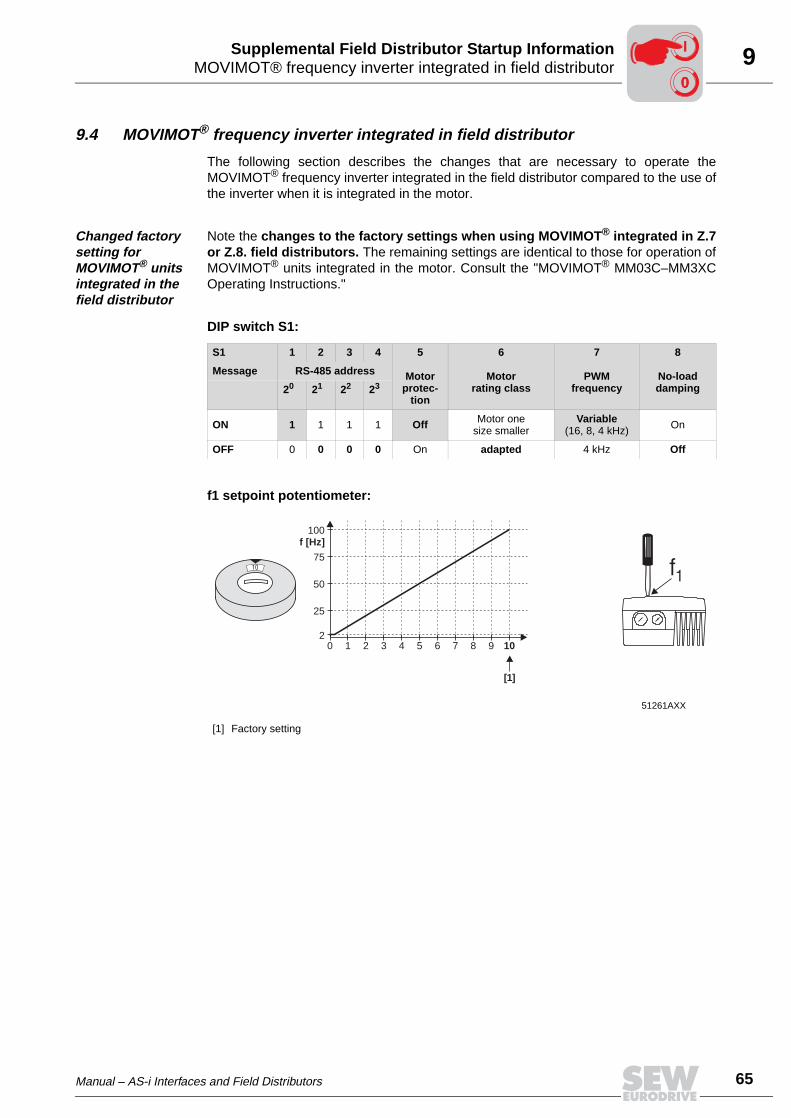
Manual – AS-i Interfaces and Field Distributors 65
9MOVIMOT® frequency inverter integrated in field distributorSupplemental Field Distributor Startup Information
9.4 MOVIMOT® frequency inverter integrated in field distributor
The following section describes the changes that are necessary to operate theMOVIMOT® frequency inverter integrated in the field distributor compared to the use ofthe inverter when it is integrated in the motor.
Changed factory setting for MOVIMOT® units integrated in the field distributor
Note the changes to the factory settings when using MOVIMOT® integrated in Z.7or Z.8. field distributors. The remaining settings are identical to those for operation ofMOVIMOT® units integrated in the motor. Consult the "MOVIMOT® MM03C–MM3XCOperating Instructions."
DIP switch S1:
f1 setpoint potentiometer:
S1 1 2 3 4 5
Motorprotec-
tion
6
Motorrating class
7
PWMfrequency
8
No-loaddamping
Message RS-485 address
20 21 22 23
ON 1 1 1 1 Off Motor onesize smaller
Variable(16, 8, 4 kHz) On
OFF 0 0 0 0 On adapted 4 kHz Off
51261AXX
[1] Factory setting
1 2 3 4 5 6 7 8 9 100
100f [Hz]
2
75
25
50
10 f1
[1]
00
I
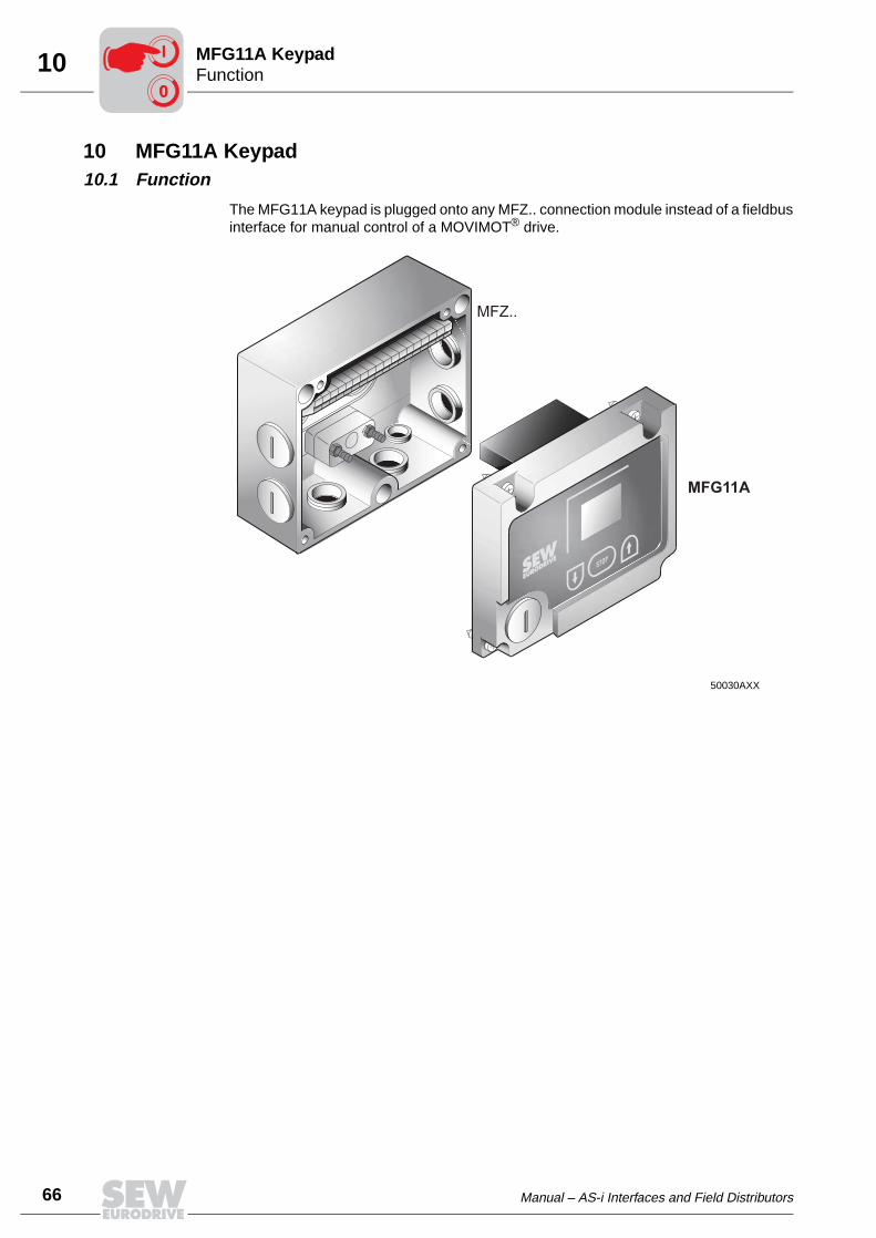
10
66 Manual – AS-i Interfaces and Field Distributors
FunctionMFG11A Keypad
10 MFG11A Keypad10.1 Function
The MFG11A keypad is plugged onto any MFZ.. connection module instead of a fieldbusinterface for manual control of a MOVIMOT® drive.
50030AXX
STOP
MFZ..
00
I

Manual – AS-i Interfaces and Field Distributors 67
10OperationMFG11A Keypad
10.2 Operation
Operation of the MFG11A option
DisplayNegative display value e.g.: = Counterclockwise rotation
Positive display value e.g.: = Clockwise rotation
The displayed value indicates the speed set with the setpoint potentiometer f1. Example: Display "50" = 50 % of the speed set with the setpoint potentiometer.Important: If the display is "0," the drive is rotating at fmin.
Increasing the speed
With CW rotation: With CCW rotation:
Reducing the speed
With CW rotation: With CCW rotation:
Blocking MOVIMOT®
Pressing the key: Display =
Enable MOVIMOT®
or
Important: After enable, MOVIMOT® accelerates to the value and direction of rotation saved last.
Changing direction of rotation from CW to CCW
1. Until display =
2. Pressing it again changes direction of rotation from CW to CCW.
Changing direction of rotation from CCW to CW
1. Until display =
2. Pressing it again changes direction of rotation from CCW to CW.
After power-on, the module is always in STOP status (display = OFF). If directionof rotation is selected with arrow key, the drive (setpoint) starts with 0.
50
50
STOP 0FF
0
0
00
I

11
68 Manual – AS-i Interfaces and Field Distributors
OperationMOVILINK® Unit Profile
11 MOVILINK® Unit ProfileThe communication between MFK.. AS-i interface and MOVIMOT® takes place accord-ing to the uniform MOVILINK® profile for SEW-Eurodrive drive inverters with three pro-cess data.
51330AXX
PO = Process output dataPO1 = Control wordPO2 = Speed (%)PO3 = Ramp
PI = Process input dataPI1 = Status word 1PI2 = Output currentPI3 = Status word 2
®
PO1 PO2 PO3
MFK..
PI1 PI2 PI3
PO
PI
MOVIMOT
00
I

Manual – AS-i Interfaces and Field Distributors 69
11OperationMOVILINK® Unit Profile
Process output data
Process output data are sent from the master controller to the MOVIMOT® inverter (con-trol information and setpoints). However, they only come into effect in MOVIMOT® if theRS-485 address in MOVIMOT® (DIP switches S1/1 to S1/4) is set to a value other than0. MOVIMOT® can be controlled with the following process output data:
• PO1: Control word
• PO2: Speed [%] (setpoint)
• PO3: Ramp
Control word, bits 0...2
The "Enable" control command is specified with bits 0...2 by entering the control word =0006hex. The CW and/or CCW input terminal must also be set to +24 V (jumpered) toenable the MOVIMOT® unit.
The "Stop" control command is issued by resetting bit 2 = "0." You should use the stopcommand 0002hex to ensure compatibility with other SEW inverter products. MOVIM-OT® always triggers a stop at the current ramp whenever bit 2 = "0," regardless of thestatus of bit 0 and bit 1.
Control word bit 6 = Reset
In the event of a malfunction, the fault can be acknowledged with bit 6 = "1" (Reset). Thevalue of unassigned control bits should be 0 to ensure compatibility.
Speed [%] The speed setpoint is specified as a percentage value in reference to the maximumspeed set with the f1 setpoint potentiometer.
Coding: C000hex = -100 % (counterclockwise rotation)
4000hex = +100 % (clockwise rotation)
→ 1 digit = 0,0061 %
Example: 80 % fmax, CCW rotation :
Calculation: –80 % / 0.0061 = –13115dec = CCC5hex
Ramp If the process data exchange takes place using three process data words, the currentintegrator ramp is transmitted in process output data word PO3 . The integrator ramp setwith switch t1 is used if MOVIMOT® is controlled by two process data.
Coding: 1 digit = 1 ms
Range: 100...10000 ms
Example: 2.0 s = 2000 ms = 2000dec = 07D0hex
Basic control block
15 14 13 12 11 10 9 8 7 6 5 4 3 2 1 0
PO1: Control word Reserved for special functions = "0" "1" = Reset reserved = "0" "1 1 0" = Release
otherwise stop
PO2: Setpoint Signed percentage / 0.0061 %Example: -80% / 0.0061 % = - 13115 = CCC5hex
PO3: Ramp (threeword protocol only)
Time from 0 to 50 Hz in ms (range: 100...10000 ms)Example: 0.2 s = 2000 ms = 07DOhex

11
70 Manual – AS-i Interfaces and Field Distributors
OperationMOVILINK® Unit Profile
Process input data
The MOVIMOT® inverter sends back process input data to the master controller. Theprocess input data consist of status and actual value information. MOVIMOT® supportsthe following process input data:
• PI1: Status word 1
• PI2: Output current
• PI3: Status word 2
15 14 13 12 11 10 9 8 7 6 5 4 3 2 1 0
Controller enable = "1"
PI1: Status word 1
Unit condition (bit 5 = "0")0 = inverter not ready2 = not enabled4 = enabled
Fault number (bit 5 = "1")
Unit enabled = "1"
PO data enabled = "1"
Reserved
Reserved
Fault/warning = "1"
Reserved
Reserved
PI2: Current actualvalue
16 bit integer with sign x 0.1 % INExample: 0320hex = 800 x 0.1 % IN = 80 % IN
PI3: Status word 2(three-word
protocol only)
15 14 13 12 11 10 9 8 7 6 5 4 3 2 1 0
Controller enable = "1"
Unit enabled = "1"
PO data enabled = "1"
Reserved
Reserved
Fault/warning = "1"
Reserved
Reserved
O1 (brake) "1" = brake applied,"0" = brake released
O2 (ready for operation)
I1 (CW)
I2 (CCW)
I3 (setpoint f2)
Reserved 0
Reserved 0
Reserved 0

Manual – AS-i Interfaces and Field Distributors 71
12MFK diagnostics interfaceMFK Diagnostics
12 MFK Diagnostics12.1 MFK diagnostics interface
Structure of the diagnostics inter-face
The diagnostics interface is located on potential level 0; the same potential as the mod-ule electronics. This setup applies to all MF../MQ.. fieldbus interfaces. The diagnosticsinterface of the MFK.. AS-i interfaces is on the MOVIMOT® potential.
The interface is accessible via a 4-pole plug connector "modular jack 4/4 (RJ11)." Theinterface is located underneath the cable gland on the module cover.
MWS21A option The diagnostics interface can be connected to a commercially available PC with a serialinterface (RS-232) using SEW’s MOVIMOT® fieldbus diagnostic kit MWS21A (part num-ber: 823 180X).
Scope of delivery of MWS21A:
• Interface adapter
• Cable with modular jack 4/4 (RJ11) plug connector
• RS-232 interface cable
• SOFTWARE-ROM 4 (MOVITOOLS software)
02876BXX
GND RS- RS+ +5V
4 3 2 1
51178AXX
UWS21A
PC + MOVITOOLS
RS-232 Modular Jack 4/4 (RJ11) MF../MQ..

12
72 Manual – AS-i Interfaces and Field Distributors
MFK diagnostics interfaceMFK Diagnostics
Relevant diag-nostics parame-ters
The MOVITOOLS Shell software can be used for diagnostics of the MOVIMOT® unitvia the diagnostics interface of the MF../MQ.. fieldbus interfaces.
Display values - 00. Process values
MOVIMOT® returns the output current as process value.
Display values - 01. Status display
MOVIMOT® status is completely interpreted and displayed on the status display.
Display values - 04. Binary input option
The digital inputs of the MF.. fieldbus interfaces are shown as optional MOVIMOT® in-puts. Since these inputs do not have a direct effect on the MOVIMOT®, the terminal as-signment is set to "No function."
Display values - 06. Binary output option
The digital outputs of the MF.. fieldbus interfaces are shown as optional MOVIMOT®
outputs. Since these outputs do not have a direct effect on MOVIMOT®, the terminal as-signment is set to "No function."
Menu number Parameter name Index Meaning / Implementation
004 Output current [%In] 8321 Output current MOVIMOT®
Menu number Parameter name Index Meaning / Implementation
010 Inverter status 8310 Inverter status MOVIMOT®
011 Operational status 8310 Operating status MOVIMOT®
012 Fault status 8310 Fault status MOVIMOT®
Menu number Parameter name Index Meaning / Implementation
040 Binary inputs DI10 8340 Status of MF.. binary inputs DI0
041 Binary inputs DI11 8341 Status of MF.. binary inputs DI1
042 Binary inputs DI12 8342 Status of MF.. binary inputs DI2
043 Binary inputs DI13 8343 Status of MF.. binary inputs DI3
044 Binary inputs DI14 8344 Status of MF.. binary inputs DI4
045 Binary inputs DI15 8345 Status of MF.. binary inputs DI5
046 Binary inputs DI10 to DI17 8348 Status of all binary inputs
Menu number Parameter name Index Meaning / Implementation
060 Binary outputs DO10 8352 Status of MF.. binary outputs DO0
061 Binary outputs DO11 8353 Status of MF.. binary outputs DO
068 Binary outputs DO10 to DO17
8360 Status of MF.. binary outputs DO0 and DO1

Manual – AS-i Interfaces and Field Distributors 73
12MFK diagnostics interfaceMFK Diagnostics
Display values - 07. Unit data
The unit data display information on the MOVIMOT® and MF.. fieldbus interface.
Display values - 09. Bus diagnos-tics
This menu item represents all fieldbus data.
Menu number Parameter name Index Meaning / Implementation
070 Unit type 8301 Unit type MOVIMOT®
072 Option 1 8362 Unit type option 1 = MF.. Type
074 Firmware option 1 8364 Firmware part number MF..
076 Firmware basic unit 8300 Firmware part number MOVIMOT®
Menu number Parameter name Index Meaning / Implementation
090 PD configuration 8451 PD configuration set for MOVIMOT®
091 Fieldbus type 8452 Fieldbus type of MF..
092 Fieldbus baud rate 8453 Baud rate of MF..
093 Fieldbus address 8454 Fieldbus address of MF.. DIP switch
094 PO1 setpoint [hex] 8455 PO1 setpoint from fieldbus master to MOVIMOT®
095 PO2 setpoint [hex] 8456 PO2 setpoint from fieldbus master to MOVIMOT®
096 PO3 setpoint [hex] 8457 PO3 Setpoint from fieldbus master to MOVIMOT®
097 PI1 actual value [hex] 8458 PI1 actual value from MOVIMOT® to fieldbus master
098 PI2 actual value [hex] 8459 PI2 actual value from MOVIMOT® to fieldbus master
099 PI3 actual value [hex] 8460 PI3 Actual value from MOVIMOT® to fieldbus master

13
74 Manual – AS-i Interfaces and Field Distributors
Status LEDMOVIMOT® Diagnostics
13 MOVIMOT® Diagnostics13.1 Status LED
The status LED is located on the top of the MOVIMOT® terminal box cover (see the fol-lowing figure).
Meaning of the status LED states
The three-color LED signals the operating and fault states.
50867AXX
[1] MOVIMOT® status LED
[1]
LED color
LED status Operational status Description
– Off Not ready No 24 V power supply
Yel-low
Steady flashing Not ready Self-test phase active or 24 V power supply present but supply voltage not OK
Yel-low
Steady, fast flashing Ready Releasing the brake without active drive enable(only with S2/2 = "ON")
Yel-low
Steady light Ready,but unit is inhibited
24 V power supply and supply voltage OK,but no enable signal
Green/yel-low
Flashing with alter-nating colors
Ready,but timeout
Faulty communication with cyclical data exchange
Green Steady light Unit enabled Motor in operation
Green Steady, fast flashing Current limit active Drive has reached the current limit
Red Steady light Not ready Check the 24 VDC supplyMake sure that there is a smoothed DC voltage with low ripple (residual ripple max. 13%) present
Red 2 x flash, pause Fault 07 DC link voltage too high
Red Flashing slowly Fault 08 Fault speed monitoring (only with S2/4="ON")
Fault 90 Assignment of motor – inverter incorrect(e.g. MM03 – DT71D4 )
Fault 17 to 24, 37 CPU fault
Fault 25, 94 EEPROM error
Red 3 x flash, pauseFault 01 Overcurrent of output stage
Fault 11 Excessive temperature in output stage
Red 4 x flash, pause Fault 84 Excessive temperature in motorIncorrect assignment of motor-frequency inverter
Red 5 x flash, pause Fault 89 Excessive temperature in brakeIncorrect assignment of motor-frequency inverter
Red 6 x flash, pause Fault 06 Mains phase fault

Manual – AS-i Interfaces and Field Distributors 75
13Table of errorsMOVIMOT® Diagnostics
13.2 Table of errors
Errors Cause / solution
Timeout of communication (motor comes to a stop without error code)
A Missing connection ⊥ , RS+, RS- between MOVIMOT® and RS-485 master. Check the connection, in particular the ground, and repair.
B EM interference. Check the shielding of the data cables and improve if necessary.C Incorrect type (cyclical) in acyclical protocol time between the individual messages.
Messages >1 s with protocol type "cyclical." Shorten message cycle orselect "acyclical."
DC link voltage too low, supply sys-tem off detected(motor stops, without fault code)
Check power cables and supply voltage for interruption. Motor restarts automatically as soon as the supply voltage reaches normal values.
Fault code 01 Overcurrent of output stage
Short circuit of inverter output.Check the connection between inverter output and motor for short circuit.
Fault code 06 Phase fault
Check power cables for phase fault. Reset the fault by switching off the 24 VDC supply voltage or use MOVILINK®.
Fault code 07 DC link voltage too high
A Ramp time too short → Increase ramp timeB Faulty connection between brake coil and braking resistor.
→ Check the connection between braking resistor and brake coil. Correct, if necessary.C Incorrect internal resistance of brake coil/braking resistor
→ Check the internal resistance of the brake coil/braking resistor(see the section "Technical Data")
D Thermal overload in braking resistor → Wrong size of braking resistor selected
Reset the fault by switching off the 24 VDC supply voltage or use MOVILINK®.
Fault code 08Speed monitoring
Speed monitoring has trippedReset the fault by switching off the 24 VDC supply voltage or use MOVILINK®.
Fault code 11 Thermal overload of the output stage or internal unit fault
• Clean the heat sink• Reduce the ambient temperature• Prevent heat accumulation• Reduce the load on the drive
Reset the fault by switching off the 24 VDC supply voltage or use MOVILINK®.
Fault code 17 to 24, 37CPU fault
Reset the fault by switching off the 24 VDC supply voltage or use MOVILINK®.
Fault code 25, 94EEPROM error
Reset the fault by switching off the 24 VDC supply voltage or use MOVILINK®.
Fault code 84 Thermal overload of motor
• Reduce the ambient temperature• Prevent heat accumulation• Reduce the load on the motor• Increase the speed• Check the combination of the drive and MOVIMOT® frequency inverter if the fault is signaled
shortly after the first release.• The temperature monitoring in the motor (TH winding thermostat) has tripped with the use of
MOVIMOT® integrated in the field distributor Z.8 and selected special function 5 → Reduce load on the motor.
Reset the fault by switching off the 24 VDC supply voltage or use MOVILINK®.
Fault code 89 Thermal overload of brake coil or brake coil defective
• Extend the set ramp time• Brake inspection (see the section "Inspection and Maintenance")• Contact SEW service• If the fault should occur shortly after the initial enable, check the combination of drive (brake
coil) and MOVIMOT® frequency inverter.
Reset the fault by switching off the 24 VDC supply voltage or use MOVILINK®.
Fault code 91 Communications fault between fieldbus gateway and MOVIMOT®
• Check electrical connection between fieldbus gateway and MOVIMOT® (RS-485)• The fault is automatically reset after removing the cause; a reset via control word is not
possible.

14
76 Manual – AS-i Interfaces and Field Distributors
MFK.. AS-i interfaceTechnical Data
14 Technical Data14.1 MFK.. AS-i interface
MFK electrical specification
Power supply to MFK control electronics (via yellow AS-i cable)
acc. to AS-i specification 2.11, max. 150 mA
Input voltage for inverter and sensors(24 V auxiliary voltage)
V = +24 V +/- 25 %
Auxiliary voltage current consump- tion ("AS-i black“)
max. 2 A, polarized(250 mA MOVIMOT® + sensor supply + actuators)
Electrical isolation Floating AS-i connection and module electronicsbetween module electronics and peripherals / MOVIMOT® / diagnostics interface via opto-coupler
Bus connection technology M12 (A-coded)
Binary inputs (sensors)Signal level
PLC-compatible to EN 61131-2 (digital inputs type 1), Ri ≈3 kΩ, sampling time approx. 5 ms+15 V...+30 V "1" = Contact made / -3 V...+5 V "0" = Contact not made
Sensor power supplyRated current
Internal voltage drop
24 VDC to EN 61131-2, interference-voltage proof and short-circuit proof Σ 500 mA max. 1 V
Binary outputs (actuators) Signal level
Rated currentLeakage currentInternal voltage drop
PLC-compatible to EN 61131-2, interference-voltage proof and short-circuit proof"0" = 0 V, "1" = 24 V500 mAmax. 0.2 mAmax. 1 V
Cable length RS-485 30 m between MFK.. and MOVIMOT® if installed separately
Ambient temperature -25 °C to +60 °C
Enclosure IP65 (assembled on MFZ.. connection module, all plug connections sealed)
AS-i specification
Protocol option AS-i slave with S-7.4 profile "Four Bit Mode Slave"
AS-i profile S-7.4
I/O configuration 7hex
ID code 4hex
Ext. ID-Code1 Fhex
Ext. ID-Code2 0hex
Address 1 to 31 (factory setting: 0)unlimited changing possible

Manual – AS-i Interfaces and Field Distributors 77
14Field distributorsTechnical Data
14.2 Field distributors
Technical data of MF.../Z.3., MQ.../Z.3.
Technical data of MF.../Z.6., MQ.../Z.6.
MF../Z.3.MQ../Z.3.
Ambient temperature -25...60 °C
Enclosure IP65 (fieldbus interface and motor connection cable attached and fastened, all plug connections sealed)
interface PROFIBUS, InterBus, DeviceNet, CANopen, AS-i
MF../Z.6.MQ../Z.6.
Maintenance switch Load disconnector and line protectionType: ABB MS 325 – 9 + HK20Switch activation: black/red, tripple lock
Ambient temperature -25...55 °C
Enclosure IP65 (fieldbus interface, power supply connection cover and motor connection cable attached and fastened, all plug connections sealed)
Interface PROFIBUS, InterBus, DeviceNet, CANopen, AS-i
Pi
fkVA
Hz
n

14
78 Manual – AS-i Interfaces and Field Distributors
Field distributorsTechnical Data
MF.../MM../Z.7., MQ.../MM../Z.7. field distributors Field distributor type MF../MM..-503-00/Z.7
MQ../MM..-503-00/Z.7
MM03C MM05C MM07C MM11C MM15C
Apparent output power at Vmains = 380...500 V
Prated 1.1 kVA 1.4 kVA 1.8 kVA 2.2 kVA 2.8 kVA
Connection voltagesPermitted range
Vmains 3 x 380 VAC / 400 VAC / 415 VAC / 460 VAC / 500 VAC Vmains = 380 VAC - 10%...500 VAC + 10%
Supply frequency fmains 50 Hz ... 60 Hz ± 10 %
Rated system current(at Vmains = 400 VAC)
Imains 1.3 AAC 1.6 AAC 1.9 AAC 2.4 AAC 3.5 AAC
Output voltage Vout 0... Vmains
Output frequencyResolutionOperating point
fout 2...100 Hz0.01 Hz400 V at 50 Hz / 100 Hz
Output rated current Irated 1.6 AAC 2.0 AAC 2.5 AAC 3.2 AAC 4.0 AAC
Motor power S1Pmot 0.37 kW 0.55 kW 0.75 kW 1.1 kW 1.5 kW
Motor power S3 25 % cdf
PWM frequency 4 / 8 / 161 kHz
1 16 kHz-PWM frequency (low-noise) If DIP-SWITCH S1/7 = ON (factory setting), the equipment operateswith 16 kHz PWM frequency (low-noise) and incrementally switches back to a lower clock frequency de-pendent upon the heat sink temperature.
Current limitation Imax Motor: 160 % with and Regenerative:160 % with and
Maximum motor lead length 15 m (with SEW hybrid cable)
External braking resistor Rmin 200 Ω
Interference immunity meets EN 61800-3
Interference emission Meets EN 61800-3 and class A limit to EN 55011 and EN 55014
Ambient temperature ϑamb -25 °C...40 °C (-13 °F...104 °F) (PN reduction: 3 % IN per K to max. 60°C)
Enclosure IP65 (fieldbus interface, supply connection cover and motor connection cable attached and screwed, all plug connections sealed)
Operating mode DB (EN 60149-1-1 and 1-3), S3 max. cycle duration 10 min-utes
Type of cooling (DIN 41 751) Self-cooling
Altitude h ≤ 1000 m (Prated reduction: 1 % per 100 m starting at an altitude of 1000 m, see also the section –Electrical Installa-tion – Installation Instructions" in the MOVIMOT® operating instructions)
External power supply to elec-tronics
Tl. 11Tl. 13
V = +24 V ± 25 %, EN 61131-2, residual ripple max. 13 %IE ≤ 250 mA (only MOVIMOT®)Starting current: 1 A
Interface PROFIBUS, InterBus, DeviceNet, CANopen, AS-i
Pi
fkVA
Hz
n

Manual – AS-i Interfaces and Field Distributors 79
14Field distributorsTechnical Data
MF../MM../Z.8., MQ../MM../Z.8. field distributors
Field distributor type MF../MM..-503-00/Z.8MQ../MM..-503-00/Z.8
MM03C MM05C MM07C MM11C MM15C MM22C MM30C MM3XC
Apparent output power at Vmains = 380...500 V
Prated 1.1 kVA 1.4 kVA 1.8 kVA 2.2 kVA 2.8 kVA 3.8 kVA 5.1 kVA 6.7 kVA
Connection voltagesPermitted range
Vmain 3 x 380 VAC / 400 VAC / 415 VAC / 460 VAC / 500 VAC Vmains = 380 VAC - 10%...500 VAC + 10%
Supply frequency fmains 50 Hz ... 60 Hz ± 10 %
Rated system current(at Vmains = 400 VAC)
Imains 1.3 AAC 1.6 AAC 1.9 AAC 2.4 AAC 3.5 AAC 5.0 AAC 6.7 AAC 8.6 AAC
Output voltage Vout 0... Vin
Output frequencyResolutionOperating point
fout 2...100 Hz0.01 Hz400 V at 50 Hz / 100 Hz
Output rated current Irated 1.6 AAC 2.0 AAC 2.5 AAC 3.2 AAC 4.0 AAC 5.5 AAC 7.3 AAC 9.6 AAC
Motor power S1Pmot 0.37 kW 0.55 kW 0.75 kW 1.1 kW 1.5 kW 2.2 kW 3.0 kW
3.0 kW
Motor power S3 25 % cdf 4.0 kW
PWM frequency 4 / 8 / 161 kHz
1 16 kHz-PWM frequency (low-noise) If DIP-SWITCH S1/7 = ON (factory setting), the equipment operates with 16 kHz PWM frequency(low-noise) and incrementally switches back to a lower clock frequency dependent upon the heat sink temperature.
Current limitation Imax Motor: 160 % with and Regenerative:160 % with and
Maximum motor lead length 15 m (with SEW hybrid cable)
External braking resistor Rmin 200 Ω 100 Ω
Interference immunity meets EN 61800-3
Interference emission Meets EN 61800-3 and class A limit to EN 55011 and EN 55014
Ambient temperature ϑamb -25 °C...40 °C (-13 °F...104 °F) (Prated reduction: 3 % Irated per K to max. 55 °C) 2
2 -25 °C...40 °C with S3 25% cdf (up to 55 °C with S3 10 % cdf)
Enclosure IP65 (fieldbus interface, supply connection cover and motor connection cable attached and screwed, all plug connections sealed)
Operating mode DB (EN 60149-1-1 and 1-3), S3 max. cycle duration 10 minutes
Type of cooling (DIN 41 751) Self-cooling
Altitude h ≤ 1000 m (Prated reduction: 1 % per 100 m starting at an altitude of 1000 m, see also the section –Electrical Installation – Installation Instructions" in the MOVIMOT® operating instruc-tions)
External power supply to electronics
Tl. 11Tl. 13
V = +24 V ± 25 %, EN 61131-2, residual ripple max. 13 %IE ≤ 250 mA (only MOVIMOT®)Starting current: 1 A
Maintenance switch Load interrupter switchType: ABB OT16ET3HS3ST1Switch activation: black/red, tripple lockable
Interface PROFIBUS, InterBus, DeviceNet, CANopen, AS-i
Pi
fkVA
Hz
n

80 Manual – AS-i Interfaces and Field Distributors
AAddress 49
Addressing device 49
AS-i cable 37
AS-i technical data 76
Assembly of fieldbus interfaces 21
CCommunication error 57
Connection cross section 32
Connection of power cables 32
C-profile rail 27
Current carrying capacity 32
DDesignated use 6Diagnosis string 57
Double tap 37, 38
EEMC 30, 35
FFunction module
Function module 1 51Function module 11 54
Function modules, description 50
IImportant Notes 6Index assignment 55
Installation altitudes 34
Installation in damp areas or in the open 20
Installation instructions 20
Installation of field distributors 24
LLED display 59
MMaintenance switch 61, 63
Metal cable glands 35
MFG11A 67
MFG11A keypad 66
Motor potentiometer 52
MOVIMOT® special functions 53
OOther applicable documents 6
PParameter transfer 55
Pre-fabricated cables 46
Process input data 70
Process output data 69
Protective devices 34
RRead Diagnosis 57
Read parameter string 56
SSafety Notes 8Single tap 41
Site of operation 7Status LED 74
Supply voltage 32
System fault 58
TTable of errors 75
Technical data of MF.../MM../Z.7., MQ.../MM../Z.7. fielddistributor 78
Technical data of MF.../Z.3., MQ.../Z.3. field distributor77
Technical data of MF.../Z.6., MQ.../Z.6. field distributor77
Technical data of MF../MM../Z.8., MQ../MM../Z.8. fielddistributor 79
UUL compliant installation 34
Unit design field distributors 13
Unit design of fieldbus interfaces 10
WWiring check 36
Write parameter string 56
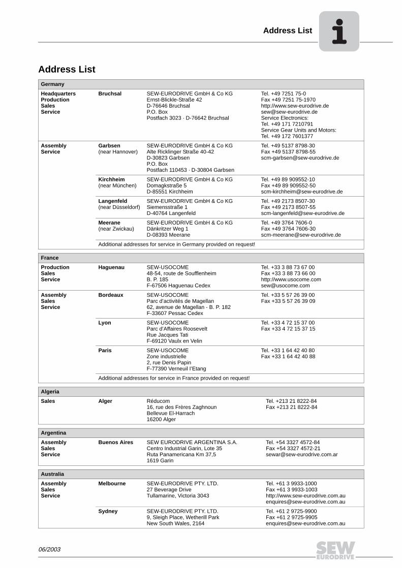
06/2003
Address List
Address ListGermany
HeadquartersProductionSalesService
Bruchsal SEW-EURODRIVE GmbH & Co KGErnst-Blickle-Straße 42 D-76646 BruchsalP.O. BoxPostfach 3023 · D-76642 Bruchsal
Tel. +49 7251 75-0Fax +49 7251 75-1970http://[email protected] Electronics:Tel. +49 171 7210791Service Gear Units and Motors:Tel. +49 172 7601377
AssemblyService
Garbsen (near Hannover)
SEW-EURODRIVE GmbH & Co KGAlte Ricklinger Straße 40-42 D-30823 GarbsenP.O. BoxPostfach 110453 · D-30804 Garbsen
Tel. +49 5137 8798-30Fax +49 5137 [email protected]
Kirchheim (near München)
SEW-EURODRIVE GmbH & Co KGDomagkstraße 5D-85551 Kirchheim
Tel. +49 89 909552-10Fax +49 89 [email protected]
Langenfeld (near Düsseldorf)
SEW-EURODRIVE GmbH & Co KGSiemensstraße 1D-40764 Langenfeld
Tel. +49 2173 8507-30Fax +49 2173 [email protected]
Meerane(near Zwickau)
SEW-EURODRIVE GmbH & Co KGDänkritzer Weg 1D-08393 Meerane
Tel. +49 3764 7606-0Fax +49 3764 [email protected]
Additional addresses for service in Germany provided on request!
France
ProductionSalesService
Haguenau SEW-USOCOME 48-54, route de Soufflenheim B. P. 185F-67506 Haguenau Cedex
Tel. +33 3 88 73 67 00 Fax +33 3 88 73 66 00http://[email protected]
AssemblySalesService
Bordeaux SEW-USOCOME Parc d’activités de Magellan62, avenue de Magellan - B. P. 182F-33607 Pessac Cedex
Tel. +33 5 57 26 39 00Fax +33 5 57 26 39 09
Lyon SEW-USOCOME Parc d’Affaires RooseveltRue Jacques TatiF-69120 Vaulx en Velin
Tel. +33 4 72 15 37 00Fax +33 4 72 15 37 15
Paris SEW-USOCOME Zone industrielle 2, rue Denis Papin F-77390 Verneuil I’Etang
Tel. +33 1 64 42 40 80Fax +33 1 64 42 40 88
Additional addresses for service in France provided on request!
Algeria
Sales Alger Réducom 16, rue des Frères ZaghnounBellevue El-Harrach16200 Alger
Tel. +213 21 8222-84Fax +213 21 8222-84
Argentina
AssemblySalesService
Buenos Aires SEW EURODRIVE ARGENTINA S.A.Centro Industrial Garin, Lote 35Ruta Panamericana Km 37,51619 Garin
Tel. +54 3327 4572-84Fax +54 3327 [email protected]
Australia
AssemblySalesService
Melbourne SEW-EURODRIVE PTY. LTD.27 Beverage DriveTullamarine, Victoria 3043
Tel. +61 3 9933-1000Fax +61 3 9933-1003http://[email protected]
Sydney SEW-EURODRIVE PTY. LTD.9, Sleigh Place, Wetherill Park New South Wales, 2164
Tel. +61 2 9725-9900Fax +61 2 [email protected]

06/2003
Address List
Austria
AssemblySalesService
Wien SEW-EURODRIVE Ges.m.b.H. Richard-Strauss-Strasse 24A-1230 Wien
Tel. +43 1 617 55 00-0Fax +43 1 617 55 00-30http://[email protected]
Belgium
AssemblySalesService
Brüssel CARON-VECTOR S.A.Avenue Eiffel 5B-1300 Wavre
Tel. +32 10 231-311Fax +32 10 231-336http://[email protected]
Brazil
ProductionSalesService
Sao Paulo SEW-EURODRIVE Brasil Ltda.Avenida Amâncio Gaiolli, 50Caixa Postal: 201-07111-970Guarulhos/SP - Cep.: 07251-250
Tel. +55 11 6489-9133Fax +55 11 6480-3328http://[email protected]
Additional addresses for service in Brazil provided on request!
Bulgaria
Sales Sofia BEVER-DRIVE GMBHBogdanovetz Str.1BG-1606 Sofia
Tel. +359 (2) 9532565Fax +359 (2) [email protected]
Cameroon
Sales Douala Electro-ServicesRue Drouot AkwaB.P. 2024Douala
Tel. +237 4322-99Fax +237 4277-03
Canada
AssemblySalesService
Toronto SEW-EURODRIVE CO. OF CANADA LTD. 210 Walker Drive Bramalea, Ontario L6T3W1
Tel. +1 905 791-1553Fax +1 905 791-2999http://[email protected]
Vancouver SEW-EURODRIVE CO. OF CANADA LTD.7188 Honeyman Street Delta. B.C. V4G 1 E2
Tel. +1 604 946-5535Fax +1 604 [email protected]
Montreal SEW-EURODRIVE CO. OF CANADA LTD.2555 Rue Leger Street LaSalle, Quebec H8N 2V9
Tel. +1 514 367-1124Fax +1 514 [email protected]
Additional addresses for service in Canada provided on request!
Chile
AssemblySalesService
Santiago de Chile
SEW-EURODRIVE CHILE LTDA.Las Encinas 1295Parque Industrial Valle GrandeLAMPARCH-Santiago de ChileP.O. BoxCasilla 23 Correo Quilicura - Santiago - Chile
Tel. +56 2 75770-00Fax +56 2 [email protected]
China
ProductionAssemblySalesService
Tianjin SEW-EURODRIVE (Tianjin) Co., Ltd.No. 46, 7th Avenue, TEDA Tianjin 300457
Tel. +86 22 25322612Fax +86 22 25322611http://www.sew.com.cn
AssemblySalesService
Suzhou SEW-EURODRIVE (Suzhou) Co., Ltd.333, Suhong Middle RoadSuzhou Industrial ParkJiangsu Province, 215021P. R. China
Tel. +86 512 62581781Fax +86 512 [email protected]

06/2003
Address List
Colombia
AssemblySalesService
Bogotá SEW-EURODRIVE COLOMBIA LTDA. Calle 22 No. 132-60Bodega 6, Manzana BSantafé de Bogotá
Tel. +57 1 54750-50Fax +57 1 [email protected]
Croatia
SalesService
Zagreb KOMPEKS d. o. o.PIT Erdödy 4 IIHR 10 000 Zagreb
Tel. +385 1 4613-158Fax +385 1 [email protected]
Czech Republic
Sales Praha SEW-EURODRIVE CZ S.R.O.Business Centrum Praha Luná 591CZ-16000 Praha 6 - Vokovice
Tel. +420 220121234 + 220121236Fax +420 220121237http://[email protected]
Denmark
AssemblySalesService
Kopenhagen SEW-EURODRIVEA/SGeminivej 28-30, P.O. Box 100DK-2670 Greve
Tel. +45 43 9585-00Fax +45 43 9585-09http://[email protected]
Estonia
Sales Tallin ALAS-KUUL ASPaldiski mnt.125EE 0006 Tallin
Tel. +372 6593230Fax +372 6593231
Finland
AssemblySalesService
Lahti SEW-EURODRIVE OYVesimäentie 4FIN-15860 Hollola 2
Tel. +358 3 589-300Fax +358 3 7806-211http://[email protected]
Gabon
Sales Libreville Electro-ServicesB.P. 1889Libreville
Tel. +241 7340-11Fax +241 7340-12
Great Britain
AssemblySalesService
Normanton SEW-EURODRIVE Ltd.Beckbridge Industrial Estate P.O. Box No.1GB-Normanton, West- Yorkshire WF6 1QR
Tel. +44 1924 893-855Fax +44 1924 893-702http://[email protected]
Greece
SalesService
Athen Christ. Boznos & Son S.A.12, Mavromichali StreetP.O. Box 80136, GR-18545 Piraeus
Tel. +30 2 1042 251-34 Fax +30 2 1042 251-59http://[email protected]
Hong Kong
AssemblySalesService
Hong Kong SEW-EURODRIVE LTD.Unit No. 801-806, 8th FloorHong Leong Industrial ComplexNo. 4, Wang Kwong Road Kowloon, Hong Kong
Tel. +852 2 7960477 + 79604654Fax +852 2 [email protected]
Hungary
SalesService
Budapest SEW-EURODRIVE Kft.H-1037 BudapestKunigunda u. 18
Tel. +36 1 437 06-58Fax +36 1 437 [email protected]

06/2003
Address List
India
AssemblySalesService
Baroda SEW-EURODRIVE India Pvt. Ltd.Plot No. 4, GidcPor Ramangamdi · Baroda - 391 243Gujarat
Tel. +91 265 2831021Fax +91 265 [email protected]
Technical Offices Bangalore SEW-EURODRIVE India Private Limited308, Prestige Centre Point7, Edward RoadBangalore
Tel. +91 80 22266565Fax +91 80 [email protected]
Mumbai SEW-EURODRIVE India Private Limited312 A, 3rd Floor, Acme PlazaAndheri Kurla Road, Andheri (E)Mumbai
Tel. +91 22 28348440Fax +91 22 [email protected]
Ireland
SalesService
Dublin Alperton Engineering Ltd. 48 Moyle RoadDublin Industrial EstateGlasnevin, Dublin 11
Tel. +353 1 830-6277Fax +353 1 830-6458
Italy
AssemblySalesService
Milano SEW-EURODRIVE di R. Blickle & Co.s.a.s.Via Bernini,14 I-20020 Solaro (Milano)
Tel. +39 2 96 9801Fax +39 2 96 [email protected]
Ivory Coast
Sales Abidjan SICASte industrielle et commerciale pour l’Afrique165, Bld de MarseilleB.P. 2323, Abidjan 08
Tel. +225 2579-44Fax +225 2584-36
Japan
AssemblySalesService
Toyoda-cho SEW-EURODRIVE JAPAN CO., LTD 250-1, Shimoman-no,Toyoda-cho, Iwata gunShizuoka prefecture, 438-0818
Tel. +81 538 373811Fax +81 538 [email protected]
Korea
AssemblySalesService
Ansan-City SEW-EURODRIVE KOREA CO., LTD. B 601-4, Banweol Industrial Estate Unit 1048-4, Shingil-DongAnsan 425-120
Tel. +82 31 492-8051Fax +82 31 [email protected]
Lebanon
Sales Beirut Gabriel Acar & Fils sarlB. P. 80484Bourj Hammoud, Beirut
Tel. +961 1 4947-86 +961 1 4982-72+961 3 2745-39Fax +961 1 4949-71 [email protected]
Luxembourg
AssemblySalesService
Brüssel CARON-VECTOR S.A.Avenue Eiffel 5B-1300 Wavre
Tel. +32 10 231-311Fax +32 10 231-336http://[email protected]
Macedonia
Sales Skopje SGS-Skopje / Macedonia"Teodosij Sinactaski” 6691000 Skopje / Macedonia
Tel. +389 2 385 466Fax +389 2 384 [email protected]
Malaysia
AssemblySalesService
Johore SEW-EURODRIVE SDN BHD No. 95, Jalan Seroja 39, Taman Johor Jaya81000 Johor Bahru, JohorWest Malaysia
Tel. +60 7 3549409Fax +60 7 [email protected]

06/2003
Address List
Morocco
Sales Casablanca S. R. M.Société de Réalisations Mécaniques 5, rue Emir Abdelkader05 Casablanca
Tel. +212 2 6186-69 + 6186-70 + 6186-71Fax +212 2 [email protected]
Netherlands
AssemblySalesService
Rotterdam VECTOR Aandrijftechniek B.V. Industrieweg 175 NL-3044 AS RotterdamPostbus 10085NL-3004 AB Rotterdam
Tel. +31 10 4463-700Fax +31 10 4155-552http://[email protected]
New Zealand
AssemblySalesService
Auckland SEW-EURODRIVE NEW ZEALAND LTD. P.O. Box 58-428 82 Greenmount driveEast Tamaki Auckland
Tel. +64 9 2745627Fax +64 9 [email protected]
Christchurch SEW-EURODRIVE NEW ZEALAND LTD. 10 Settlers Crescent, FerrymeadChristchurch
Tel. +64 3 384-6251Fax +64 3 [email protected]
Norway
AssemblySalesService
Moss SEW-EURODRIVE A/SSolgaard skog 71N-1599 Moss
Tel. +47 69 241-020Fax +47 69 [email protected]
Peru
AssemblySalesService
Lima SEW DEL PERU MOTORES REDUCTORES S.A.C.Los Calderos # 120-124Urbanizacion Industrial Vulcano, ATE, Lima
Tel. +51 1 3495280Fax +51 1 [email protected]
Poland
AssemblySalesService
Lodz SEW-EURODRIVE Polska Sp.z.o.o.ul. Techniczna 5 PL-92-518 Lodz
Tel. +48 42 67710-90Fax +48 42 67710-99http://[email protected]
Portugal
AssemblySalesService
Coimbra SEW-EURODRIVE, LDA. Apartado 15 P-3050-901 Mealhada
Tel. +351 231 20 9670Fax +351 231 20 3685http://[email protected]
Romania
SalesService
Bucuresti Sialco Trading SRL str. Madrid nr.4 71222 Bucuresti
Tel. +40 21 230-1328Fax +40 21 230-7170 [email protected]
Russia
Sales St. Petersburg ZAO SEW-EURODRIVE P.O. Box 263 RUS-195220 St. Petersburg
Tel. +7 812 5357142 +812 5350430Fax +7 812 [email protected]
Senegal
Sales Dakar SENEMECA Mécanique GénéraleKm 8, Route de Rufisque B.P. 3251, Dakar
Tel. +221 849 47-70Fax +221 849 [email protected]
Singapore
AssemblySalesService
Singapore SEW-EURODRIVE PTE. LTD. No 9, Tuas Drive 2 Jurong Industrial Estate Singapore 638644
Tel. +65 68621701 ... 1705Fax +65 68612827Telex 38 659 [email protected]

06/2003
Address List
Slovenia
SalesService
Celje Pakman - Pogonska Tehnika d.o.o.UI. XIV. divizije 14SLO – 3000 Celje
Tel. +386 3 490 83-20Fax +386 3 490 [email protected]
South Africa
AssemblySalesService
Johannesburg SEW-EURODRIVE (PROPRIETARY) LIMITEDEurodrive House Cnr. Adcock Ingram and Aerodrome RoadsAeroton Ext. 2Johannesburg 2013P.O.Box 90004Bertsham 2013
Tel. +27 11 248-7000Fax +27 11 [email protected]
Capetown SEW-EURODRIVE (PROPRIETARY) LIMITED Rainbow ParkCnr. Racecourse & Omuramba RoadMontague GardensCape TownP.O.Box 36556Chempet 7442 Cape Town
Tel. +27 21 552-9820Fax +27 21 552-9830Telex 576 [email protected]
Durban SEW-EURODRIVE (PROPRIETARY) LIMITED2 Monaceo PlacePinetownDurbanP.O. Box 10433, Ashwood 3605
Tel. +27 31 700-3451Fax +27 31 [email protected]
Spain
AssemblySalesService
Bilbao SEW-EURODRIVE ESPAÑA, S.L. Parque Tecnológico, Edificio, 302E-48170 Zamudio (Vizcaya)
Tel. +34 9 4431 84-70Fax +34 9 4431 [email protected]
Sweden
AssemblySalesService
Jönköping SEW-EURODRIVE ABGnejsvägen 6-8S-55303 JönköpingBox 3100 S-55003 Jönköping
Tel. +46 36 3442-00Fax +46 36 3442-80http://[email protected]
Switzerland
AssemblySalesService
Basel Alfred lmhof A.G.Jurastrasse 10 CH-4142 Münchenstein bei Basel
Tel. +41 61 41717-17Fax +41 61 41717-00http://[email protected]
Thailand
AssemblySalesService
Chon Buri SEW-EURODRIVE (Thailand) Ltd.Bangpakong Industrial Park 2700/456, Moo.7, Tambol DonhuarohMuang DistrictChon Buri 20000
Tel. +66 38 454281Fax +66 38 [email protected]
Tunisia
Sales Tunis T. M.S. Technic Marketing Service7, rue Ibn EI Heithem Z.I. SMMT2014 Mégrine Erriadh
Tel. +216 1 4340-64 + 1 4320-29Fax +216 1 4329-76
Turkey
AssemblySalesService
Istanbul SEW-EURODRIVE Hareket Sistemleri Sirketi Bagdat Cad. Koruma Cikmazi No. 3 TR-81540 Maltepe ISTANBUL
Tel. +90 216 4419163 + 216 4419164 + 216 3838014Fax +90 216 [email protected]

06/2003
Address List
USA
ProductionAssemblySalesService
Greenville SEW-EURODRIVE INC. 1295 Old Spartanburg Highway P.O. Box 518Lyman, S.C. 29365
Tel. +1 864 439-7537Fax Sales +1 864 439-7830Fax Manuf. +1 864 439-9948Fax Ass. +1 864 439-0566Telex 805 550 http://[email protected]
AssemblySalesService
San Francisco SEW-EURODRIVE INC. 30599 San Antonio St.Hayward, California 94544-7101
Tel. +1 510 487-3560Fax +1 510 [email protected]
Philadelphia/PA SEW-EURODRIVE INC. Pureland Ind. Complex 2107 High Hill Road, P.O. Box 481Bridgeport, New Jersey 08014
Tel. +1 856 467-2277Fax +1 856 [email protected]
Dayton SEW-EURODRIVE INC.2001 West Main Street Troy, Ohio 45373
Tel. +1 937 335-0036Fax +1 937 [email protected]
Dallas SEW-EURODRIVE INC.3950 Platinum Way Dallas, Texas 75237
Tel. +1 214 330-4824Fax +1 214 [email protected]
Additional addresses for service in the USA provided on request!
Venezuela
AssemblySalesService
Valencia SEW-EURODRIVE Venezuela S.A.Av. Norte Sur No. 3, Galpon 84-319Zona Industrial Municipal NorteValencia, Estado Carabobo
Tel. +58 241 832-9804Fax +58 241 [email protected]@cantv.net

SEW-EURODRIVE GmbH & Co KG · P.O. Box 3023 · D-76642 Bruchsal/GermanyPhone +49 7251 75-0 · Fax +49 7251 75-1970
http://www.sew-eurodrive.com · [email protected]
Related Documents