ARM to MIPS® Architecture Migration Guide Document Number: MD00874 Revision 00.10 May 15, 2011 MIPS Technologies, Inc. 955 East Arques Ave Sunnyvale, CA 94085 Copyright ©2011 MIPS Technologies, Inc. All rights reserved.

Welcome message from author
This document is posted to help you gain knowledge. Please leave a comment to let me know what you think about it! Share it to your friends and learn new things together.
Transcript

ARM to MIPS® Architecture Migration Guide
Document Number: MD00874 Revision 00.10 May 15, 2011
MIPS Technologies, Inc. 955 East Arques Ave Sunnyvale, CA 94085
Copyright ©2011 MIPS Technologies, Inc. All rights reserved.

ARM to MIPS® Architecture Migration Guide
Copyright ©2011 MIPS Technologies Inc. All rights reserved.
2
Copyright ©2011 MIPS Technologies, Inc. All rights reserved.
Unpublished rights (if any) reserved under the copyright laws of the United States of America and other countries.
This document contains information that is proprietary to MIPS Technologies, Inc. ("MIPS Technologies"). Any copying, reproducing,
modifying or use of this information (in whole or in part) that is not expressly permitted in writing by MIPS Technologies or an authorized third
party is strictly prohibited. At a minimum, this information is protected under unfair competition and copyright laws. Violations thereof may result in criminal penalties and fines.
Any document provided in source format (i.e., in a modifiable form such as in FrameMaker or Microsoft Word format) is subject to use and
distribution restrictions that are independent of and supplemental to any and all confidentiality restrictions. UNDER NO CIRCUMSTANCES MAY A DOCUMENT PROVIDED IN SOURCE FORMAT BE DISTRIBUTED TO A THIRD PARTY IN SOURCE FORMAT WITHOUT
THE EXPRESS WRITTEN PERMISSION OF MIPS TECHNOLOGIES, INC.
MIPS Technologies reserves the right to change the information contained in this document to improve function, design or otherwise. MIPS Technologies does not assume any liability arising out of the application or use of this information, or of any error or omission in such
information. Any warranties, whether express, statutory, implied or otherwise, including but not limited to the implied warranties of
merchantability or fitness for a particular purpose, are excluded. Except as expressly provided in any written license agreement from MIPS Technologies or an authorized third party, the furnishing of this document does not give recipient any license to any intellectual property rights,
including any patent rights, that cover the information in this document.
The information contained in this document shall not be exported, re-exported, transferred, or released, directly or indirectly, in violation of the law of any country or international law, regulation, treaty, Executive Order, statute, amendments or supplements thereto. Should a conflict arise
regarding the export, re-export, transfer, or release of the information contained in this document, the laws of the United States of America shall
be the governing law.
The information contained in this document constitutes one or more of the following: commercial computer software, commercial computer
software documentation, or other commercial items. If the user of this information, or any related documentation of any kind, including related
technical data or manuals, is an agency, department, or other entity of the United States government ("Government"), the use, duplication, reproduction, release, modification, disclosure, or transfer of this information, or any related documentation of any kind, is restricted in
accordance with Federal Acquisition Regulation 12.212 for civilian agencies and Defense Federal Acquisition Regulation Supplement 227.7202
for military agencies. The use of this information by the Government is further restricted in accordance with the terms of the license agreement(s) and/or applicable contract terms and conditions covering this information from MIPS Technologies or an authorized third party.
MIPS, MIPS I, MIPS II, MIPS III, MIPS IV, MIPS V, MIPS-3D, MIPS16, MIPS16e, MIPS32, MIPS64, MIPS-Based, MIPSsim, MIPSpro,
MicroMIPS, MIPS Technologies logo, MIPS RISC CERTIFIED POWER logo, MIPS-Verified, M14K, 1004Kc, 1004Kf, 1074Kc, 1074Kf, 4K, 4Kc, 4Km, 4Kp, 4KE, 4KEc, 4KEm, 4KEp, 4KS, 4KSc, 4KSd, M4K, 5K, 5Kc, 5Kf, 20K, 20Kc, 24K, 24Kc, 24Kf, 24KE, 24KEc, 24KEf, 25Kf,
34K, 34Kc, 34Kf, 74K, 74Kc, 74Kf, R3000, R4000, R5000, ASMACRO, Atlas, "At the core of the user experience.", BusBridge, CorExtend,
CoreFPGA, CoreLV, EC, JALGO, Malta, MDMX, MGB, PDtrace, the Pipeline, Pro Series, QuickMIPS, SEAD, SEAD-2, SmartMIPS, SOC-it, and YAMON are trademarks or registered trademarks of MIPS Technologies, Inc. in the United States and other countries.
All other trademarks referred to herein are the property of their respective owners.

ARM to MIPS® Architecture Migration Guide
Copyright ©2011 MIPS Technologies Inc. All rights reserved.
3
Contents
Introduction ..................................................................................................................................... 4
Programming model........................................................................................................................ 5
Instruction set .................................................................................................................................. 7
CPU initialization............................................................................................................................ 8
Exception vector and exception types........................................................................................... 10
Migrating applications .................................................................................................................. 17
Summary ....................................................................................................................................... 18

ARM to MIPS® Architecture Migration Guide
Copyright ©2011 MIPS Technologies Inc. All rights reserved.
4
Introduction
The purpose of this document is to describe the ease of migration from an ARM7, ARM9 or
ARM11 to the MIPS® architecture and cores.
MIPS Technologies supports the MIPS32® and MIPS64® instruction set architectures. MIPS64
allows 64-bit addressing modes to facilitate larger virtual address space. Migration from the
MIPS32 to the MIPS64 architecture is a seamless path.
ARM is a 32-bit architecture . Beyond 32-bit and 64-bit, both MIPS and ARM supports 16 bit
instructions for improved code density. Both architectures also support floating point.
Typically the application code running on these architectures is coded in a high level language
such as C or C++, so porting between architectures is straightforward. MIPS provides a GNU
tool chain that that can efficiently recompile the code to a MIPS platform. The extensive
ecosystem for MIPS provides a variety of operating systems, software development tools and
platforms from a broad range of vendors.
The bulk of the migration effort between architectures involves low-level boot code and device
initialization. The areas that need special attention are: programming model, virtual to physical
address mapping differences, cache and TLB initialization, differences in exception vectors and
exception types and interrupt exceptions. For assembly code translation, the user needs to
understand the differences in instruction set and register calling conventions.
This document is not meant to be an architecture reference manual nor a software users guide.
The purpose of this document is to illustrate the differences in areas that need special attention
by the user and also provides sample code segments for initialization of the resources.
The user is encouraged to refer to the following documents for further reading and references:
MIPS32® Architecture for Programmers Volume I: Introduction to the MIPS32® Architecture
MIPS32® Architecture for Programmers Volume II: The MIPS32® Instruction Set
MIPS® Architecture for Programmers Volume III: The MIPS32® and microMIPS32™
Privileged Resource Architecture
YAMON™ Porting Requirements Specification
YAMON™ User's Manual
Details on tools and software, development kits, reference and users manuals and application
notes can be found at mips.com.
ARM to MIPS® Architecture Migration Guide
Copyright ©2011 MIPS Technologies Inc. All rights reserved.
5
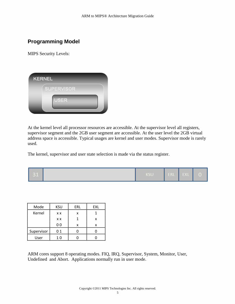
Programming Model
MIPS Security Levels:
At the kernel level all processor resources are accessible. At the supervisor level all registers,
supervisor segment and the 2GB user segment are accessible. At the user level the 2GB virtual
address space is accessible. Typical usages are kernel and user modes. Supervisor mode is rarely
used.
The kernel, supervisor and user state selection is made via the status register.
Mode KSU ERL EXL
Kernel x x x 1
x x 1 x
0 0 x x
Supervisor 0 1 0 0
User 1 0 0 0
ARM cores support 8 operating modes. FIQ, IRQ, Supervisor, System, Monitor, User,
Undefined and Abort. Applications normally run in user mode.

ARM to MIPS® Architecture Migration Guide
Copyright ©2011 MIPS Technologies Inc. All rights reserved.
6
MIPS handles interrupt exceptions, undefined instructions and memory access violations in the
kernel mode.
MIPS32 architecture specifies fixed memory map. The address space is divided into 4 regions:
kseg2, TLB-mapped cacheable kernel space
kseg1, direct-mapped uncached kernel space
kseg0, direct-mapped cached kernel space
kuseg, TLB-mapped cacheable user space
kseg0 and kseg1 segments are direct mapped and map to the first 512 megabytes of the physical
address space. The rest of the regions are TLB-mapped and cacheable. Reset vector is
0xBFC00000 – kseg1. All exceptions default to kseg1 and can be relocated to kseg0 upon
enabling of caches.
The ARM reset vector defaults to 0x00000000 or 0xFFFF0000 based on the SCTLR.V bit. When
the MMU is enabled the vector table can be located anywhere in the memory. The MMU and the
MPU allow several different regions of memory with different protection and cache-ability
attributes in ARM cores. Address space is flat and address translation takes place in mapped
regions.
The following figure shows the virtual address to physical address mapping of the modes
supported in MIPS cores:

ARM to MIPS® Architecture Migration Guide
Copyright ©2011 MIPS Technologies Inc. All rights reserved.
7
Instruction set
Instruction sets for MIPS and ARM are similar. MIPS also supports application specific
extensions (ASE) for DSP, security, multi-threading and other technologies. The CorExtend™
feature enables user defined instructions to be part of the core instructions set. All instruction in
ARM can be conditionally executed based on ALU condition codes. MIPS provides conditional
branches only. The MIPS ISA is fully backward-compatible and to some extent the ARMs
architecture is also backward-compatible. The following table lists the classes of
instructions that both architectures support.

ARM to MIPS® Architecture Migration Guide
Copyright ©2011 MIPS Technologies Inc. All rights reserved.
8
ARM1136JF-S™ MIPS32® 24Kc™
Add ADD{cond}{S} <Rd>, <Rn>, <operand2> ADD rd, rs, rt
Subtract SUB{cond}{S} <Rd>, <Rn>, <operand2> SUB rd, rs, rt
Multiply MUL{cond}{S} <Rd>, <Rm>, <Rs> MUL rd, rs, rt
Multiply-accumulate MLA{cond}{S} <Rd>, <Rm>, <Rs>, <Rn> MADD rs, rt
Count leading zeros CLZ{cond} <Rd>, <Rm> CLZ rd, rs
AND AND{cond}{S} <Rd>, <Rn>, <operand2> ADD rd, rs, rt
XOR EOR{cond}{S} <Rd>, <Rn>, <operand2> XOR rd, rs, rt
OR ORR{cond}{S} <Rd>, <Rn>, <operand2> OR rd, rs, rt
Branch B{cond} <label> J target
Branch with link BL{cond} <label> JAL target
Branch and exchange BX{cond} <Rm> JALX target
Word LDR{cond} <Rd>, <a_mode2> LW rt, offset(base)
Byte LDR{cond}B <Rd>, <a_mode2> LBU rt, offset(base)
Byte signed LDR{cond}SB <Rd>, <a_mode3> LB rt, offset(base)
Halfword LDR{cond}H <Rd>, <a_mode3> LHU rt, offset(base)
Halfword signed LDR{cond}SH <Rd>, <a_mode3> LH rt, offset(base)
Word STR{cond} <Rd>, <a_mode2> SW rt, offset(base)
Byte STR{cond}B <Rd>, <a_mode2> SB rt, offset(base)
Halfword STR{cond}H <Rd>, <a_mode3> SH rt, offset(base)
Move to ARM reg from
coproc
MRC{cond} <cp_num>, <op1>, <Rd>, <CRn>,
<CRm>{, <op2>} MFC0 rt, rd, sel
Move to coproc from ARM
reg
MCR{cond} <cp_num>, <op1>, <Rd>, <CRn>,
<CRm>{, <op2>} MTC0 rt, rd, sel
Signed add high 16 + 16, low
16 + 16, set GE flags SADD16{cond} <Rd>, <Rn>, <Rm> ADDQ.PH rd,rs,rt
Saturated add high 16 + 16,
low 16 + 16 QADD16{cond} <Rd>, <Rn>, <Rm> ADDQ_S.PH rd,rs,rt
Signed high 16 - low 16, low
16 + high 16, set GE flags SSUBADDX{cond} <Rd>, <Rn>, <Rm> SUBQ.PH rd,rs,rt
Saturated high 16 - low 16,
low 16 + high 16 QSUBADDX{cond} <Rd>, <Rn>, <Rm> SUBQ_S.PH rd,rs,rt
Four saturated unsigned 8 + 8 UQADD8{cond} <Rd>, <Rn>, <Rm> ADDU_S.QB rd, rs, rt
Four saturated 8 - 8 QSUB8{cond} <Rd>, <Rn>, <Rm> ADD_S.QB rd, rs, rt
Four saturated unsigned 8 - 8 UQSUB8{cond} <Rd>, <Rn>, <Rm> SUBU_S.QB rd, rs, rt

ARM to MIPS® Architecture Migration Guide
Copyright ©2011 MIPS Technologies Inc. All rights reserved.
9
CPU Initialization
The cache architecture for both the ARM and MIPS architectures are fairly similar: independent
L1 for instruction and data and common a L2. MIPS caches are 1, 2 or 4 ways set associate and
the line size is 4 or 8 words. Both architectures support write-back and write-thru options.
Caches are disabled at reset.
The following code segments show cache operations for a MIPS32 24Kc core and the
ARM1136JF-S:
Function ARM1136JF-S™ MIPS32® 24Kc™
Enabling
Cache
MRC p15, 0, r0, c1, c0, 0 ; read
CP15 register 1 into r0
ORR r0, r0, #(0x1 <<12) ; enable I
Cache
ORR r0, r0, #(0x1 <<2) ; enable D
Cache
MCR p15, 0, r0, c1, c0, 0 ; write
CP15 register 1
mfc0 t0, C0_Config1
/* set kseg0 as Cacheable, noncoherent, write-back, write allocate */
ori t0,t0, 0x3
mtc0 t0, C0_Config1
Function ARM1136JF-S™ MIPS32® 24Kc™
Invalidate
Cache
MRC p15,0,R0,c0,c0,1 ; Read cache type reg
AND R0,R0,#0x1C0000 ; Extract D cache size
MOV R0,R0, LSR #18 ; Move to bottom bits
ADD R0,R0,#7 ; Get Index loop max
MOV R1,#3:SHL:30 ; Set up Set = 3
MOV R2,#0 ; Set up Index counter
MOV R3,#1
MOV R3,R3, LSL R0 ; Set up Index loop max
index_loop
ORR R4,R2,R1 ; Way and Set format
MCR p15,0,R4,c7,c14,2 ; Clean&inval D cache
line
ADD R2,R2,#1:SHL:5 ; Increment Index
CMP R2,R3 ; Done all index values?
BNE index_loop ; Loop until done
mfc0 a1, C0_Config1
and a1, M_Config1IL
srl a1, S_Config1IL
li v0, 0x2
sll v0, a1 /* a1 = I-cache line size */
mfc0 t9, C0_Config1
and t8, t9, M_Config1IA
srl t8, S_Config1IA
addiu t8, 1 /* t8 = associativity */
and t9, M_Config1IS
srl t9, S_Config1IS
li t7, 0x40
sll t7, t9 /* t7 = sets per way */
multu t8, t7
mflo a0 /* a0=cache size */
MTC0( zero, C0_TagHi )
MTC0( zero, C0_TagLo )
0:
li a2, KSEG0BASE /* Calc 1st cache line address*/
addu a3, a2, a0 /* Calc last cache line address*/
subu a3, a1
1: /* Loop through all lines, invalidating each of them */
cache ICACHE_INDEX_STORE_TAG, 0(a2) /* clear tag */
bne a2, a3, 1b
addu a2, a1

ARM to MIPS® Architecture Migration Guide
Copyright ©2011 MIPS Technologies Inc. All rights reserved.
10
TLB initialization:
Both the ARM and MIPS architectures support virtual-to-physical address translation via TLB
scheme. Page sizes ranging from 4KB to 256MB are supported by both architectures. In the
MIPS architecture, on a TLB miss, a system exception is raised and an exception handler loads
the appropriate configuration in the TLB. In the ARM architecture, TLB misses are handled in
hardware by a two-level page table walk mechanism. MIPS also supports a couple of simpler
schemes - Fixed address translation and Block address translation. ARM supports such schemes
via the Memory Protection Unit (MPU).
The following code segment shows TLB initialization:
Function ARM1136JF-S™ MIPS32® 24Kc™
Initialize
TLB Entry
- N/A void initTLBEntryByIndex (int idx) {
int i;
__asm__ __volatile ("move $t0, %0" : : "r"
(idx));
__asm__ __volatile (
"mtc0 $t0, $0, 0;" // set index
"lui $t1, 0xa000;"
"sll $t0, $t0, 16;"
"or $t1, $t0,$t1;"
"mtc0 $t1, $10,0;" //entryhi
"mtc0 $zero, $2,0;" //entrylo0
"mtc0 $zero, $3,0;" //entrylo1
"mtc0 $zero, $5,0;" //pagemask
"tlbwi;"
"ehb;"
);
return;
}

ARM to MIPS® Architecture Migration Guide
Copyright ©2011 MIPS Technologies Inc. All rights reserved.
11
Exception vector and exception type
The following table is a summary of the exception vector and types for the MIPS and ARM
architectures:
The following tables list the details of exception vector, exception types and priorities for the
ARM and MIPS architectures:
ARM Exception vector address(V=0, V=1) Mode on entry
MIPS Exception vector address (SI_UseExceptionBase, Status.BEV, Status.EXL, Cause.IV, EJTAG ProbEn)
Exception Types
0x0000.0000, 0xFFFF.0000 Supervisor
16#BFC0.0000 Reset, NMI
0x0000.0004, 0xFFFF.0004 Undefined
16#BFC0.0200 Other, TLB Refill
0x0000.0008, 0xFFFF.0008 Supervisor
16#BFC0.0300 Cache Error
0x0000.000C, 0xFFFF.000C Prefetch Abort
16#BFC0.0380 TLB Refill, Interrupt, All Others
0x0000.0010, 0xFFFF.0010 Data Abort
16#BFC0.0400 Interrupt
0x0000.0014, 0xFFFF.0014 Reserved
16#BFC0.0480 EJTAG Debug
0x0000.0018, 0xFFFF.0018 IRQ
16#8000.0180 TLB Refill, Interrupt, All Others
0x0000.001C, 0xFFFF.001C FIQ
16#8000.0280 Interrupt
16#A000.0100 Cache Error
16#FF20.0200 EJTAG Debug
EBase31..30=2#10 || 1 || EBase28..12 || EBase12..0=16#000
Cache Error
EBase31..30=2#10 || 1 || EBase28..12 || EBase12..0=16#480
EJTAG Debug
ARM1136JF-S™ MIPS32® 24Kc™
Support 7 different types/priorities of
exceptions
Support 35 different types/priorities of exceptions:
offering the programmer more knowledge of what went
wrong and allowing the user to handle it differently
Exception base is predefined to 0x0000.0000
and 0xFFFF.0000
Exception base is predefined to 0xBFC0.0000 and
0x8000.0000
Exception base can be changed by EBase

ARM to MIPS® Architecture Migration Guide
Copyright ©2011 MIPS Technologies Inc. All rights reserved.
12
EBase31..30=2#10 || EBase29..12 || EBase12..0=16#000
All Others, Reset, NMI
EBase31..30=2#10 || EBase29..12 || EBase12..0=16#200
All Others, TLB Refill
EBase31..30=2#10 || EBase29..12 || EBase12..0=16#380
TLB Refill, Interrupt, All Others
EBase31..30=2#10 || EBase29..12 || EBase12..0=16#400
Interrupt
EBase31..30=2#10 || EBase29..12 || EBase12..0=16#480
EJTAG Debug
2#101 || SI_ExceptionBase[28:12] || 16#300
Cache Error
ARM1136JF-S™ MIPS32® 24Kc™ Priority Name Priority Name Description
1 Reset (highest priority). 1 Reset
Assertion of SI_Reset signal
2 DSS EJTAG Debug Single Step
3 DINT
EJTAG Debug Interrupt.; caused by the assertion of the external EJ_DINT input, or by setting the EjtagBrk bit in the ECR register
4 DDBLImpr/DDBSImpr Debug Data Break Load/Store Imprecise
5 NMI Asserting edge of SI_NMI signal
2 Precise Data Abort. 6 Machine Check TLB write that conflicts with an existing entry
3 FIQ. 7 Interrupt
Assertion of unmasked hardware or software interrupt signal
4 IRQ.
7 SWI (lowest priority)
8 Deferred Watch
Deferred Watch (unmasked by K|DM->!(K|DM) transition)
9 DIB
EJTAG debug hardware instruction break matched

ARM to MIPS® Architecture Migration Guide
Copyright ©2011 MIPS Technologies Inc. All rights reserved.
13
10 WATCH
A reference to an address in one of the watch registers (fetch)
6 Prefetch Abort. 11 AdEL
Fetch address alignment error; fetch reference to protected address.
2 Precise Data Abort. 12 TLBL
Fetch TLB miss; fetch TLB hit to page with V=0
13 ICache Error Parity error on ICache access
5 Imprecise Data Aborts. 14 IBE
Instruction fetch bus error
15 DBp
EJTAG Breakpoint (execution of SDBBP instruction)
16 Sys Execution of SYSCALL instruction
7 BKPT 17 Bp Execution of BREAK instruction
18 CpU
Execution of a coprocessor instruction for a coprocessor that is not enabled
19 CEU
Execution of a CorExtend instruction modifying local state when CorExtend is not enabled
7 Undefined instruction 20 RI
Execution of a Reserved Instruction
21 FPE Floating Point exception
22 C2E Coprocessor2 Exception
23 IS1
Implementation specific Coprocessor2 exception
24 Ov
Execution of an arithmetic instruction that overflowed
25 Tr
Execution of a trap (when trap condition is true)
26 DDBL / DDBS EJTAG Data Address Break (address only)
27 WATCH
A reference to an address in one of the watch registers (data)
2 Precise Data Abort. 28 AdEL Load address alignment

ARM to MIPS® Architecture Migration Guide
Copyright ©2011 MIPS Technologies Inc. All rights reserved.
14
error. Load reference to protected address
2 Precise Data Abort. 29 AdES
Store address alignment error. Store to protected address
2 Precise Data Abort. 30 TLBL
Load TLB miss. Load TLB hit to page with V=0
2 Precise Data Abort. 31 TLBS
Store TLB miss. Store TLB hit to page with V=0
2 Precise Data Abort. 32 TLB Mod Store to TLB page with D=0
5 Imprecise Data Aborts. 33 DCache Error
Cache parity error - imprecise
5 Imprecise Data Aborts. 34 L2 Cache Error
L2 Cache ECC error - imprecise
5 Imprecise Data Aborts. 35 DBE
Load or store bus error - imprecise
Interrupt exception
The MIPS and ARM architectures have similar interrupt schemes. The MIPS architecture has an
integrated interrupt controller that supports up to 6 priorities in VI mode and up to 63 priorities
in EIC mode. The ARM architecture requires an external interrupt controller to support VI mode.
External interrupts are mapped to FIQ and IRQ; hence faster response times on the MIPS
architecture. The MIPS architecture also has a cause register that reflects the cause of the
interrupt. The following table summarizes the interrupt schemes for each architecture:
The following table details the interrupt exceptions for ARM and MIPS.
ARMv5 MIPS32® 24Kc™
ARM1136JF-S™ MIPS32® 24Kc™
Two types FIQ and IRQ One type but 3 operating modes (Compatibility, VI,
EIC)
Bank registers for supporting better interrupt
response
Shadow register for better interrupt service response
Maximum 16 active registers can be used Maximum 32 active registers can be used
Need to handshake with external interrupt
controller to get effective vector address
Has faster interrupt response time (CPU will calculate
the vector address
ARM to MIPS® Architecture Migration Guide
Copyright ©2011 MIPS Technologies Inc. All rights reserved.
15
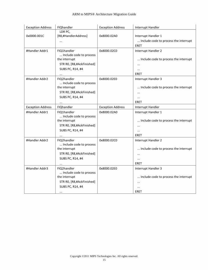
Exception Address FIQhandler Exception Address Interrupt Handler
0x0000.001C LDR PC, [R8,#HandlerAddress] 0x8000.02A0 Interrupt Handler 1
... ... Include code to process the interrupt
ERET
#Handler Addr1 FIQ1handler 0x8000.02C0 Interrupt Handler 2
... Include code to process the interrupt ... Include code to process the interrupt
STR R0, [R8,#AckFinished] ...
SUBS PC, R14, #4 ...
... ERET
#Handler Addr2 FIQ2handler 0x8000.02E0 Interrupt Handler 3
... Include code to process the interrupt ... Include code to process the interrupt
STR R0, [R8,#AckFinished] ...
SUBS PC, R14, #4 ...
... ERET
Exception Address FIQhandler Exception Address Interrupt Handler
#Handler Addr1 FIQ1handler 0x8000.02A0 Interrupt Handler 1
... Include code to process the interrupt ... Include code to process the interrupt
STR R0, [R8,#AckFinished] ...
SUBS PC, R14, #4 ...
... ERET
#Handler Addr2 FIQ2handler 0x8000.02C0 Interrupt Handler 2
... Include code to process the interrupt ... Include code to process the interrupt
STR R0, [R8,#AckFinished] ...
SUBS PC, R14, #4 ...
... ERET
#Handler Addr3 FIQ2handler 0x8000.02E0 Interrupt Handler 3
... Include code to process the interrupt ... Include code to process the interrupt
STR R0, [R8,#AckFinished] ...
SUBS PC, R14, #4 ...
... ERET

ARM to MIPS® Architecture Migration Guide
Copyright ©2011 MIPS Technologies Inc. All rights reserved.
16
Application Binary Interface (ABI)
When coding in assembly, the ARM architecture provides 6 active registers (vx) for arithmetic
and load store operations. The MIPS architecture provides 18 active registers (tx + sx). The
MIPS architecture provides 32 general purpose registers, while ARM has only 16 active
registers. A larger register set eases register pressure for compiled code.
The following table shows the register calling convention for ARM and MIPS:
Number Name Purpose Number Name Purpose
$0 $0 Always 0
$1 $at
The Assembler Temporary used by the
assembler in expanding pseudo-ops.
r12 Ip
Intra-procedure-call scratch
register $2-$3 $v0-$v1
These registers contain the Returned Value of a
subroutine; if the value is 1 word only $v0 is
significant.
r0-r3 a1-a4
Argument, result, or scratch
registers $4-$7 $a0-$a3
The Argument registers, these registers contain
the first 4 argument values for a subroutine call.
r4-r11 v1-v8 Variable registers
$8-$15,
$24,$25 $t0-$t9 The Temporary Registers.
$16-$23 $s0-$s7 The Saved Registers.
$26-$27 $k0-$k1 The Kernel Reserved registers. DO NOT USE.
r9 sb Static base $28 $gp
The Global Pointer used for addressing static
global variables. For now, ignore this.
r13 sp Stack pointer $29 $sp The Stack Pointer.
r11 fp Frame pointer $30 $fp (or $s8)
The Frame Pointer: programs that do not use an
explicit frame pointer (e.g., everything assigned
in ECE314) can use register $30 as another
saved register – not recommended however
r14 lr Link register $31 $ra The Return Address in a subroutine call
r15 pc Program counter

ARM to MIPS® Architecture Migration Guide
Copyright ©2011 MIPS Technologies Inc. All rights reserved.
17
Migrating applications
Reset, initialization and exception handling are typically done in assembly, but it is common that
the application itself is coded in C/C++ (high level language). The application and any device
drivers must be recompiled with the MIPS tool chain. Any assembly code can be translated
manually, as there is almost a one-to-one equivalent instruction.
The bulk of the effort in migration entails changes to the initialization and low level boot code.
MIPS Technologies provides the YAMON™ PROM monitor as reference code that runs on
MIPS development boards. There are boot loaders available from third party vendors and open
source.
On both the ARM and MIPS architectures, applications normally will run in user mode. On an
exception, ARM will switch to Supervisor mode and MIPS will enter the kernel mode. The
exception handler switches the mode back to user mode upon handling the exception. On ARM
stacks and stack pointers for each mode need to be initialized. Only the kernel stack needs to be
initialized on MIPS. Exceptions save context in reserved memory space.
Memory map on the MIPS architecture is fixed and user space is kuseg segment of the memory.
Kseg0-3 is reserved for kernel. Cached system data resides in kseg0 and uncached in kseg1.
ARM allows the system data and user code to be mapped to anywhere in the valid address range.
I/O devices in the MIPS architecture are mapped in kseg1 and anywhere in valid memory range
on the ARM architecture.
In both ARM and MIPS most of the exception handling is done in software. ARM supports two
external interrupt handlers, namely FIQ and IRQ. FIQ is normally used for low latency interrupts
and has a higher priority. Nested interrupts are typically handled by IRQ through a 2 -stage
interrupt handler. The nested IRQ handler must save the registers on the system stack before
enabling the interrupts, in order to prevent corruption of the return address.
MIPS supports six external interrupts, and each can be masked independently. Nested interrupts
are handled in a similar fashion. Exception context must be saved before re-enabling the
interrupts. Configuring interrupts is straightforward in the MIPS architecture. Only the status
register fields must be programmed.
The MIPS ISA defines both MIPS32 and MIPS64. MIPS64 offers larger virtual address and
physical address space, and MIPS32 applications can be seamlessly migrated to MIPS64 to take
advantage of the 64-bit pointers. Long word is 128 bits in MIPS64 and in both MIPS32 and
MIPS64, char is 8-bit unsigned. MIPS provides N32 and N64 ABIs for embedding assembly
code with C/C++.
MIPS Technologies offers the MIPS Navigator™ Integrated Component Suite (ICS) that comes
with a GNU compiler and debugger, JTAG level debugger, profiler and event analyzer. Several
other software vendors also provide tool suite for MIPS processors.
ARM to MIPS® Architecture Migration Guide
Copyright ©2011 MIPS Technologies Inc. All rights reserved.
18
Summary
MIPS Technologies licenses its MIPS32 and MIPS64 architectures, and also offers single-core,
multi-core, superscalar and multi-threaded families of cores based on the MIPS32 architecture.
Several of MIPS Technologies’ licensees also offer high-performance, multicore products based
on the MIPS64 architecture.
With its architectures and cores, MIPS has a large footprint in digital home and networking
applications, and growing traction in mobile devices.
MIPS cores are the industry’s most area efficient, offering high performance at the lowest power
dissipation. With its multi-threading technology, companies can efficiently implement a
parallelizable application by maximizing the instructions per cycle (IPC). The QoS features in
the multi-threaded family of products help ensure real-time application performance. The breadth
and the rich features of MIPS’ product portfolio, coupled with a flexible business model, enable
MIPS licensees to create MIPS-Based products that range from 32-bit microcontrollers and
energy efficient mobile devices to ‘green’ supercomputers and high end networking
infrastructure.
Related Documents