AMERICAN RAILWAY ENGINEERING AND MAINTENANCE OF WAY ASSOCIATION COMMUNICATIONS & SIGNALS MANUAL VOLUME 5 SECTION 18 – INSIDE PLANT SECTION 19 – ELECTRICAL PROTECTION SECTION 20 – INDUCTIVE INTERFERENCE SECTION 21 – DATA TRANSMISSION SECTION 22 – RADIO 2002 AREMA Committees Developing C&S Manual Parts AREMA Committee 36- Highway-Rail Grade Crossing Warning Systems Subcommittee 36-1 Warning System Controls Subcommittee 36-2 Warning System Installation & Maintenance Subcommittee 36-3 Warning System Equipment Subcommittee 36-4 Intelligent Transportation Systems AREMA Committee 37- Signal Systems Subcommittee 37-1 Signal Systems Subcommittee 37-2 Signal Equipment Subcommittee 37-3 Signal Control & Applications AREMA Committee 38- Information, Defect Detection & Energy Systems Subcommittee 38-1 Equipment Applications Subcommittee 38-2 Electromagnetic Compatibility Subcommittee 38-3 Energy Systems Subcommittee 38-4 Radio/Wireless

AREMA Communictaions and Signals
Dec 28, 2015
Welcome message from author
This document is posted to help you gain knowledge. Please leave a comment to let me know what you think about it! Share it to your friends and learn new things together.
Transcript
AMERICAN RAILWAY ENGINEERING AND MAINTENANCE OF WAY ASSOCIATION
COMMUNICATIONS & SIGNALS MANUAL
VOLUME 5 SECTION 18 – INSIDE PLANT SECTION 19 – ELECTRICAL PROTECTION SECTION 20 – INDUCTIVE INTERFERENCE SECTION 21 – DATA TRANSMISSION SECTION 22 – RADIO
2002 AREMA Committees Developing C&S Manual Parts AREMA Committee 36- Highway-Rail Grade Crossing Warning Systems Subcommittee 36-1 Warning System Controls Subcommittee 36-2 Warning System Installation & Maintenance Subcommittee 36-3 Warning System Equipment Subcommittee 36-4 Intelligent Transportation Systems AREMA Committee 37- Signal Systems Subcommittee 37-1 Signal Systems Subcommittee 37-2 Signal Equipment Subcommittee 37-3 Signal Control & Applications AREMA Committee 38- Information, Defect Detection & Energy Systems Subcommittee 38-1 Equipment Applications Subcommittee 38-2 Electromagnetic Compatibility Subcommittee 38-3 Energy Systems
Subcommittee 38-4 Radio/Wireless

This page intentionally left blank
AMERICAN RAILWAY ENGINEERING AND MAINTENANCE OF WAY ASSOCIATION
COMMUNICATIONS & SIGNALS MANUAL OF RECOMMENDED PRACTICE
(2002) VOLUME 5
A recommended practice is a design, plan, instruction, information or any proposition of importance recommended in the interest of establishing uniformity, promoting safety or efficiency and economy. A recommended practice does not in any way imply or otherwise suggest inadequacy of practices that may not conform thereto. In addition, it is recognized that federal, state, provincial, or municipal laws and regulations may, where applicable, be at variance with the recommended practice. Each Manual Part will have any one of the following dates:
New - Date the Part was first approved for inclusion in the Manual.
Revised - Year in which the Part was revised. Reaffirmed - Date on which the Part was reviewed and found
to be technically correct. Therefore it is still a recommended practice.
Extended - Date indicates that the Part is under review
and that further action will be taken. Your comments about the Communications & Signals Manual and the information it contains are most welcome. Comments and questions of interpretation or application should be addressed to Executive Director, American Railway Engineering and Maintenance of Way Association, 8201 Corporate Drive, Suite 1125, Landover, MD 20785-2230.
Printed in U.S.A.
COPYRIGHT 2002: ALL RIGHTS RESERVED. THIS MANUAL, OR PARTS THEREOF, MAY NOT BE REPRODUCED IN ANY FORM WITHOUT PERMISSION OF THE AMERICAN RAILWAY ENGINEERING AND MAINTENANCE OF WAY ASSOCIATION. SPECIAL NOTE: THE AREMA COMMUNICATIONS AND SIGNALS MANUAL OF RECOMMENDED PRACTICE WILL UPDATE THE LOOK OF ITS MANUAL PARTS OVER THE NEXT FIVE YEARS, STARTING IN 2002. NOT ALL MANUAL PA RTS WILL HAVE THE SAME STYLE DURING THIS PROCESS.

This page intentionally left blank
AREMA® C&S Manual 2002 Subject Index
-1-
Subject Index for Manual Parts Revised 2002 (24 Pages)
AC relays 6.1.21, 6.1.35, 6.1.40
Instructions 6.4.5 Adapter clamp for signs 3.2.80 Adjacent track interconnected highway-rail grade crossing warning systems 3.1.11 Adjustable lock rod 12.2.15, 12.2.16 Adjustment bracket
Vertical switch lock rod Bolt fastening 12.1.18 Parts 12.1.19, 12.1.20 Stud fastening 12.1.16
Vertical switch throw rod Bolt fastening 12.1.17 Parts 12.1.19, 12.1.20 Stud fastening 12.1.15
Administration Section 1 Advance operating times Calculate for highway-rail grade crossing warning devices 3.3.10 Air depreciated primary battery 9.1.25 Aligning flashing-light signals 3.3.5 Alloys, non-ferrous 15.1.5 Aluminum conductors steel reinforced 10.3.11 Analog data transmission 21.1.2 Approach lighting, vital circuits 16.4.2 Arm, gate 3.2.15, 3.2.20
Gate, wood 3.2.25, 3.2.26, 3.2.30A through 3.2.30C Light unit 3.2.40
Armored signal cable 10.3.17 Arresters, lightning, see Electrical Surge Protection Aspects, flashing (not crossing signals) 2.1.5 Assembly of insulated track fittings 8.5.1 Audio frequency track circuits 8.2.1, 8.6.10 Automatic block
End of sign 2.1.50B Automatic block signaling 2.2.1
Instructions 2.4.3 Automatic block signaling circuits 2.2.1 Automatic Equipment Identification (AEI) site configuration 5.3.2 Automatic speed control with continuous cab signaling 16.4.50 Ball socket screw jaw for switch circuit controller 12.1.7 Ball studs for switch circuit controller 12.1.2 Bases 7.2.35, 7.2.36A, 7.2.36B, 7.2.40, 7.2.41A, 7.2.41B, 7.2.45A, 7.2.45B, 7.2.46A,
AREMA® C&S Manual Subject Index 2002
-2-
7.2.46B Batteries
Air alkaline 9.1.26 Air depreciated primary 9.1.25 Applications 9.1.30 Chargers 9.2.1, 9.2.5 Disposal and recycling 9.5.5 Lead-acid storage 9.1.1, 9.1.2, 9.1.3, 9.5.3, 9.5.4 Nickel-cadmium 9.1.15, 9.5.2 Standby requirements for highway-rail grade crossing warning systems 3.1.28 Storage, instructions 9.5.1 Valve regulated 9.1.4, 9.1.16
Begin CTC sign 2.1.50C Begin TCS sign 2.1.50F Bell, highway-rail grade crossing warning devices 3.2.60, 3.2.61 Binding posts 14.1.10, 14.1.11, 14.1.12 Block, end of (sign) 2.1.50A Block, end of automatic (sign) 2.1.50B Blocks, terminal Molded 14.1.5, 14.1.8 Multiple unit 14.1.6 Screw clamp type 14.1.2 Short type 14.1.7 Boilerplate in Manual Parts 1.4.1, 6.5.1, 7.5.1 Bolts 14.1.1, 14.6.20 For highway-rail grade crossing signs 3.2.96A through 3.2.96C Bond compound, impedance 8.4.6 Bond, impedance 8.4.5 Fire-resistant dielectric 8.4.8 Instructions 8.6.30 Bonding, track circuit 8.1.20 Bond oil, impedance 8.4.7 Bonds, See Rail Head/Web Bonds Bond Strand 10.3.12 Brackets, extension for crossing signs 3.2.85 Breakaway gate arm adapter 3.2.21 Bridge circuit coupler 2.2.36 Cable Section 10 - See also listings under Wire
Chlorosulfonated polyethylene and neoprene jacketing 10.3.20 Cross-linked polyethylene insulation and jacketing 10.3.22 Ethylene propane rubber insulation 10.3.19 Instructions 10.4.1 Low smoke halogen free 10.3.13 Polyvinyl chloride insulation and jacketing 10.3.23 Purpose & meaning of terms used in Manual Parts 10.3.40
AREMA® C&S Manual 2002 Subject Index
-3-
Polyethylene insulation and jacketing 10.3.21 Signal
Armored 10.3.17 Non-armored 10.3.16
Synthetic rubber insulation 10.3.18 Calculations
Approach warning time for highway-rail grade crossings 3.3.10 Minimum allowable resistance between track battery and track 8.1.5 Time release applied to signal apparatus 2.4.20 Track circuit readings 8.1.10 Train shunt resistance 8.1.11
Canadian Electrical Code 11.1.5 Cantilevers for highway-rail grade crossing warning devices 3.2.5, 3.2.10 Cap for junction box base 7.2.50 Car detector 5.1.45, 5.1.47 Car retarders Distributive 4.2.13
Electric 4.2.10 Electro-hydraulic 4.2.12 Electro-Pneumatic 4.2.11
Carriers, pipe 13.1.57 Case platform 14.4.25 Castings
Gray iron 15.1.1 Malleable iron 15.1.2
Cathodic protection 8.6.15 Centralized traffic control 2.2.11, 2.2.15 Charger, battery
Constant current 9.2.5 Constant voltage 9.2.1
Chromaticity 7.1.10 Circuit protection Section 11 Circuits
Automatic block signaling 2.2.1 Design guidelines Section 16 Nomenclature 16.1.1 Non-vital relays 6.3.1, 6.3.5 Vital circuit design guidelines Sections 16.3, 16.4, 16.5, 16.6, 16.9, 16.30
Circuits, track Section 8 Instructions 8.6.1 Minimize lightning, see Electrical Surge Protection
Circuit, end of (sign) 2.1.50D Circuit coupler for movable bridge 2.2.30 Circuit controller, switch 12.1.1
Ball socket screw jaw 12.1.7 Ball studs 12.1.2
AREMA® C&S Manual Subject Index 2002
-4-
Insulated rod 12.1.6 Rods 12.1.5
Clamp, adapter for signs 3.2.80 Classification yard Computer to control 4.1.10 Control console 4.2.1 Distribute retarder 4.2.13 Inspection and test 4.3.1 Installation 4.1.1 Insulated joint location 4.1.5 Signaling 4.1.15 Clean cab locomotive radio 22.2.1, 22.1.1Clearances, overhead cable, 2.4.1 Climbing step 7.2.30 Coatings, metallic 15.3.1 Coded track circuit unit Non-resonant 8.3.1
Phase-Selective 8.4.1 Resonant 8.4.1, 8.4.2 Codes NESC, NEC, CEC 11.1.5 Color light signal, doublet lens 7.1.1 Color light signal searchlight type 7.1.14 Color light switch position indicator 7.3.1 Color position light signal 7.1.3 Colors, signal paint for signs, targets, etc. 15.3.10 Commercial communication facilities 20.1.4 Communication facilities 19.1.14, 20.1.8 Compensator
Cranks 13.1.46 Link 13.1.47 Pipe 13.1.45 Component placement 11.2.2 Compound, impregnation of electrical windings 15.2.1 Compound Filling recesses & sealing 15.2.15
Insulating 15.2.3 Computer to control a classification yard 4.1.10 Concrete foundations, precast 14.4.lA through 14.4.11 Concrete pier for instrument housings 14.4.11 Condensation, minimize
Instructions 1.5.5 Conduit
Steel pipe 14.6.31 Cones, signal 7.1.10 Connectors
AREMA® C&S Manual 2002 Subject Index
-5-
Ground rod 11.3.4, 11.4.1 Terminal 14.1.15 Track circuit 8.1.25
Consoles, classification yard 4.2.1 Constant current battery charger 9.2.5 Constant voltage battery charger 9.2.1 Constant warning time device for highway-rail grade crossing warning systems 3.1.26 Control of highway-rail grade crossing warning devices 3.1.15
Constant warning time devices 3.1.26 Controllers 3.1.25 Motion sensors 3.1.20
Controller, switch circuit 12.1.1 Ball socket screw jaw 12.1.7 Ball studs 12.1.2 Insulated rod 12.1.6 Rods 12.1.5
Cotters 14.6.22 Coupling, 1 in. pipe 13.1.6 Crank 13.1.38
Pins 13.1.50 Pipe compensator 13.1.46
Crank stand 13.1.35, 13.1.36 Crossarm for flashing-light signal 3.2.50, 3.2.51 Crossbuck sign 3.2.70, 3.2.71, 3.2.90 Cross-linked polyethylene insulation & jacketing for wire & cable 10.3.22 Crossovers, fouling protection 2.1.15 Current, foreign
Minimize on dc track circuit 8.6.15 CTC, Begin (sign), End (sign) 2.1.50C DC relays 6.1.1, 6.1.2, 6.1.5, 6.1.10, 6.1.15, 6.1.20, 6.1.21, 6.1.25, 6.1.30, 6.1.45, 6.2.1,
6.3.1, 6.3.5 Instructions 6.4.1
DC track circuit Minimize foreign current 8.6.15 Test record 8.1.10
Decoding transformer 8.3.10 Decoding unit 8.3.5 Definitions and Terms
Definitions for technical terms in signaling 1.1.1 Wire and cable 10.3.40 Surge protection 11.3.10
Design guidelines - vital circuits Section 16 Designation plate, relay contact post 6.1.50 Detectors
Car 5.1.45
AREMA® C&S Manual Subject Index 2002
-6-
Dragging equipment 5.1.1, 2.4.1 Falling rock 2.4.1, 5.1.12 Flat wheel 5.1.25 High, wide load 5.1.20 Hot bearing 5.1.30 Hot wheel 5.1.35 Inspection and testing 5.3.6 Rock slide 2.4.1, 5.1.12, Wheel 5.1.50 Wheel crack 5.1.40
Dielectric requirements for signal equipment 11.5.1 Dielectric, impedance bond fire-resistant 8.4.8 Discs
Signal 7.1.10 Distribute retarder 4.2.13 Dragging equipment detector 5.1.1 Drill rail bond holes, instructions 8.6.25 Electric car retarders 4.2.10 Electric lamps, incandescent 14.2.1, 14.7.1 Electric light unit
Flashing-light signals 3.2.35 Gate arm 3.2.40, 3.2.45 Indicators & signs 7.3.6
Electric locks 2.1.25 Electric locking
Instructions for testing 2.4.5 Electric motor switch operating mechanism 12.2.1 Electric switch locks 12.4.5 Electrical crossings 20.1.1 Electrical protection Section 11 Electrical safety 11.1.1 Electrical supply facilities 20.1.4 Electrical supply lines 20.1.1 Electrical surge protection, 11.2.1, 11.3.1, 11.3.2, 11.3.3, 11.3.4, 11.3.10, 11.4.1, 11.4.2,
19.1.10 Electrical windings
Insulating compound 15.2.1 Varnish 15.2.2
Electronic track circuits 8.1.2 Electro-pneumatic car retarder 4.2.11 Electrostatic discharge control program 19.1.20 End of automatic block sign 2.1.50B End of block sign 2.1.50A End of CTC sign 2.1.50C End of circuit sign 2.1.50D
AREMA® C&S Manual 2002 Subject Index
-7-
End TCS sign 2.1.50F End of train device (TIS) 22.3.1 Environmental criteria, electrical and electronic signal equipment 11.5.1 Equipment, solid state
Installation, maintenance and test 1.5.1 Extension bracket for crossing signs 3.2.85 Exothermic welded bonds 8.1.32, 8.1.33, 8.1.34 Facility, joint signal agreement 1.3.1 Falling rock detector 5.1.12 Faraday shielding 11.3.10, 11.4.2 Fire-resistant dielectric, impedance bond 8.4.8 Flasher
DC relay 6.1.45 Rate for crossing signal 3.1.1 Solid state for crossing signals 3.2.55
Flashing aspects (not crossing signals) 2.1.5 Flashing-light signal
Alignment 3.3.5 Application 3.1.5 Cantilever mounting 3.2.5, 3.2.10 Crossarm 3.2.50, 3.2.51 Electric light unit 3.2.35
Flat wheel detector 5.1.25 FM transeiver (radio) 22.2.3 Foreign current, minimize on dc track circuit 8.6.15 Fouling protection on turnouts & crossovers 2.1.15 Foundations, galvanized steel 14.4.17, 14.4.19,
14.4.21, 14.4.21A. 14.4.23 Foundations, pour-in-place 14.4.30, 14.4.31, 14.4.32, 14.4.33, 14.4.34, 14.4.35, 14.4.36 Foundations, precast concrete 14.4.lA, 14.4.8A through 14.4.11 Foundations, ladders 7.2.55 Frequencies, radio, allocated 22.1.2 Frequencies, radio, channels 22.1.1 Friction tape 14.6.35 Frost conditions, instructions to minimize 1.5.5 Gasket material 15.2.10 Gate (highway-rail grade crossing) Application 3.1.5
Arm 3.2.20 Four quadrant (exit) 3.1.5, 3.2.15
Light unit for arm 3.2.40 Limited clearance combination 3.2.10
Operating mechanism 3.2.15 Wind Support 3.2.22

AREMA® C&S Manual Subject Index 2002
-8-
With flashing-light signal 3.2.12 Wood arm 3.2.25, 3.2.26, 3.2.30A through 3.2.30C Gate arm (breakaway) adapter 3.2.21 Gauge, switch obstruction 12.4.10 Grade crossings - see Highway-Rail Grade Crossing Warning System Grade signal marker 2.1.41 Graphical symbols 16.2.l through 16.2.l9 Gray iron castings 15.1.1 Grease, pressure gun Identical Criteria 15.5.1
Lime soap base 15.4.6 Lithium soap base 15.4.5 Ground rods (electrodes)
Copper clad 11.3.4 Chemically enhanced 11.3.5 Made ground 11.4.1
Grounds Communication facilities 19.1.14 Installation, see Electrical Surge Protection
Instructions 11.4.2 Hand-operated switches 2.1.25 Highway-rail grade crossing warning systems Sec. 3 Adjacent track 3.1.11 Aligning flashing-light signals 3.3.5 Application guidelines 3.1.5
Audio frequency track circuit 8.2.1, 8.6.10 Battery requirements 3.1.28
Bell 3.2.60, 3.2.61 Bolts for signs 3.2.96A through 3.2.96C Breakaway gatearm 3.2.21
Calculating advance operating times 3.3.10 Cantilever
combinations 3.2.10 Location Plan 3.1.35 Mounting of flashing light signals 3.2.2, 3.2.5
Circuits: design guidelines, Manual Part Section 16 Clamp for signs 3.2.80 Complete assembly, gate, flashers, cantilever span 3.2.2
Constant warning time control 3.1.26, 3.3.20 Control 3.1.15
Controllers 3.1.25 Crossarm for flashing-light signals 3.2.50, 3.2.51
Extension bracket for signs 3.2.85 Flashing-light signal applications 3.1.5 Flashing-light signal assembly drawings 3.2.2
AREMA® C&S Manual 2002 Subject Index
-9-
Flashing light rate 3.1.1 Gate arm
Break away 3.2.21 Four quadrant (exit) 3.1.5, 3.2.15 Self restoring 3.2.23 Tubular/telescopic 3.2.20, 3.2.24 Wood 3.2.25, 3.2.26 Wood anticulated 3.2.30A, 3.2.30B, 3.2.30C
Gate mechanism 3.1.5, 3.2.10, 3.2.15 Inspection and test 3.3.30
Installation center turn lane 3.1.37 Insulated joint locations 3.1.30 Interconnected 3.1.11 Interconnection with highway traffic signals 3.1.10 Interrupt 3.1.10 Light for gate arm 3.2.40 Light unit for flashing-light signal
Incandescent 3.2.35 Light emitting diodes 3.2.35
Location plans 3.1.35, 3.1.36, 3.1.36A through 3.1.36L Locomotive, clean cab radio 22.2.1
Maintenance, testing, inspection and instructions 2.4.1, 3.3.1 Mast (See cantilever)
Monitoring 3.1.29, 3.1.29A Motion sensor control 3.1.20, 3.3.15 Preemption 3.1.10 Signs 3.2.65, 3.2.70, 3.2.71, 3.2.75, 3.2.90
Solid-state flasher 3.2.55 Standby battery requirements 3.1.28 Symbols, graphical 3.1.31 Warning devices operating guidelines 3.1.1 Warning devices functional guidelines 3.1.36 Warning time, determining 3.3.10
High, wide load detector 5.1.20 Horizontal crank stand 13.1.35, 13.1.39 Hot bearing detector 5.1.30 Site selection 5.3.1 Hot wheel detector 5.1.35 Identical items ("Boilerplate") for all Manual Parts 1.4.1 Illuminated indicators and signs 7.3.5, 7.3.7, 7.3.8 Electric light unit 7.3.6 Roundels 7.3.9 Impedance bond 8.4.5
Compound 8.4.6 Fire-resistant dielectric 8.4.8
AREMA® C&S Manual Subject Index 2002
-10-
Instructions 8.6.30 Oil 8.4.7
Impulse transformer 14.2.25 Incandescent electric lamps 14.2.1, 14.7.1 Indicator
Electric light unit 7.3.6 Illuminated 7.3.5, 7.3.7, 7.3.8 Switch position 7.3.1 Take or leave siding 2.1.45
Inductive Coordination 20.1.4, 20.1.6, 20.1.7 Inductive Effects 20.1.8 Inspection and test Classification yards 4.3.1 Defect detectors 5.3.6 Highway-rail grade crossing warning systems 3.3.30 Signal Systems 2.4.1 Installation
AC relays 6.4.5 Communication facilities 19.1.14 Computer control of a classification yard 4.1.10 DC relays 6.4.1 Drill rail holes for plug bonds 8.6.25 Highway-rail grade crossing warning systems 3.3.30 Impedance bonds 8.6.30 Insulated rail joints 8.6.35 Incandescent electric lamps 14.7.1 Interlockings 2.4.10 Lead-Acid Storage Batteries 18.1.36 Light signals 7.4.1 Made grounds 11.4.1 Minimize foreign current in dc track circuits 8.6.15 Movable bridge signals 2.4.15 Rail head/web bonds 8.6.25, 8.6.40 Solid state equipment 1.5.1 Storage batteries 9.5.1 Time releases 2.4.20 Track circuits 8.6.1 Wire and cable 10.4.1, 10.4.40 Yard systems 4.1.1
Instructions AC relays 6.4.5 Aligning flashing-light signals 3.3.5 Audio frequency track circuits 8.6.10 Automatic block signaling 2.4.3 Batteries 9.5.1, 9.5.2, 9.5.3, 9.5.4, 9.5.5 Cable 10.4.1

AREMA® C&S Manual 2002 Subject Index
-11-
Calculating advance operating times for highway-rail grade crossing warning systems 3.3.10
Classification yards 4.3.1 Constant warning time devices 3.3.20 DC relays 6.4.1 Defect detectors 5.3.6 Drill rail bond holes for plug bonds 8.6.25 Electric locking 2.4.5 Electric switch locks 12.5.5, 2.4.1 Facing point locks 12.5.15 Highway-rail grade crossing warning systems 3.3.1, 3.3.30 Hot bearing detector site selection 5.3.1 Impedance bonds 8.6.30 Incandescent electric lamps 14.7.1 Insulated rail joints 8.6.35 Insulation resistance testing 10.4.30 Interlockings 2.4.10, 2.4.1 Light signals 7.4.1, 2.4.1 LP gas winter switch protection devices 12.5.20 Made grounds 11.4.1 Minimize foreign current in dc track circuits 8.6.15 Minimize frost and condensation 1.5.5 Motion sensors 3.3.15 Movable bridge signals 2.4.15 Oil burning winter switch protection devices 12.5.21 Painting 1.5.10 Rail head/web bonds 8.6.25, 8.6.40 Signal installations 2.4.1 Solid state equipment 1.5.1 Spring switches 12.5.10, 12.5.15, 2.4.1 Storage batteries 9.5.1, 9.5.2, 9.5.3, 9.5.4, 9.5.5 Switches, derails 2.4.1 Switch circuit controller 12.5.1, 2.4.1 Time releases 2.4.20 Track circuits 3.3.25, 8.6.1, 2.4.1 Wire 10.4.1, 10.4.40
Insulated joint location 2.1.20A, 2.1.20B, 2.1.20C, 2.1.20D Fouling protection 2.1.15 Grade crossing 2.1.20E Island circuit 3.1.30
Insulated rail joints At highway-rail grade crossings 3.1.30 Car retarder locations 4.1.5 Instructions 8.6.35 Locations 2.1.20A through 2.1.20E
Insulated signal wire 10.3.15
AREMA® C&S Manual Subject Index 2002
-12-
Insulated terminals 14.1.15 Insulated track fittings 8.5.1, 8.5.2, 8.5.3 Insulating compound
Filling recesses 15.2.3 Impregnation of electrical windings 15.2.1
Insulation Cross-linked polyethylene for wire & cable 10.3.22 Ethylene propane rubber for wire & cable 10.3.19 Polyethylene for wire and cable 10.3.21 Polyvinyl chloride for wire and cable 10.3.23 Synthetic rubber for wire and cable 10.3.18
Insulation, pipe line, 1 in. 13.1.25 Insulation resistance testing 10.4.30 Interlocking 2.2.10, 2.2.11
Microprocessor 2.2.12 Movable bridge 2.4.10
Interlockings Traffic control 2.2.2 Microprocessor based 2.2.12
Iron castings Gray iron 15.1.1 Malleable 15.1.2
Isolation of power supplies 16.3.2 Jacketing
Cross-linked polyethylene for wire and cable 10.3.22 Neoprene and chlorosulfonated polyethylene for wire and cable 10.3.20 Polyethylene for wire and cable 10.3.21 Polyvinyl chloride for wire and cable 10.3.23
Jaws Ends, tang and plain 13.1.21 Links 13.1.21 Pins 13.1.50 Screw ball socket for switch circuit controller 12.1.7 Screw with tang end 13.1.30, 13.1.15 Solid with tang ends 13.1.20, 13.1.15
Joints, rail insulated, instructions 8.6.35 Joints, rail insulated, location 2.1.20A through 2.1.20E
Car retarder location 4.1.5 At highway-rail crossings, railroad crossings 3.1.30
Joint signal facility agreement 1.3.1 Junction box base for signals 7.2.36A, 7.2.36B, 7.2.41A, 7.2.41B, 7.2.46A, 7.2.46B,
7.2.50 Ladder foundations 7.2.55 Lamps, electric incandescent 14.2.1, 14.7.1
AREMA® C&S Manual 2002 Subject Index
-13-
Lamps, semaphore, lens hood 7.1.30 Lamps, switch, lens hood 7.1.30 Lead-acid storage batteries 9.1.1, 9.1.2, 9.1.3, 18.1.36 Leave siding indicator 2.1.45 Lens hoods for switch and semaphore lamps 7.1.30 Lens Doublet 7.1.1 Lenses, signals 7.1.10 Letters and numerals 14.6.2A, 14.6.3 Light, electric
Gate arm 3.2.40 Highway-rail grade crossing warning signals 3.2.35 Indicators and signs 7.3.6
Light emitting diode (LED) 3.2.35 Light out detection, vital circuit design guidelines 16.4.30 Light signals, See Section 7
Application of light units to mast 7.2.1 Chromaticity 7.1.10 Color light 7.1.1 Color position light 7.1.3 Electronic Control 2.1.10 Fixed 2.1.1 Flashing Aspect 2.1.5 Identical items 7.5.1 Instruction 7.4.1 Position light 7.1.2 Search light 7.1.4
Lightning Arresters, see Electrical Surge Protection
Lime soap base, pressure gun grease 15.4.6 Line circuit reactor 14.2.20 Line circuits, double feed 16.5.1 Line circuits TCS 16.50.2 Line wire 10.3.10 Lithium soap base, pressure gun grease 15.4.5 Lock, electric 2.1.25 Lock rod, adjustable 12.2.15, 12.2.16 Locking, electric, instructions for testing 2.4.5 Locking, time, vital circuits 16.4.1 Locks, switch, electric 12.4.5 Loss of shunt, circuits 16.4.8 LP gas winter switch protection devices 12.5.20 Lubricant, electro-pneumatic valves and cylinders 15.4.10 Lubrication oil 15.4.1 Lug
Point 12.1.10, 12.1.11 Tang end 13.1.47
AREMA® C&S Manual Subject Index 2002
-14-
Maintain light signals 7.4.1 Maintenance
AC relays 6.4.5 Automatic block signaling 2.4.3 Communication facilities 19.1.14 DC relays 6.4.1 Electric switch locks 12.5.5 Highway-rail grade crossing warning systems 3.3.1 Impedance bonds 8.6.30 Incandescent electric lamps 14.7.1 Insulated rail joints 8.6.35 Interlockings 2.4.10 Lead-Acid Storage Batteries 18.1.36 Light signals 7.4.1 LP gas winter switch protection devices 12.5.20 Made grounds 11.4.1 Minimizing foreign current in dc track circuits 8.6.15 Movable bridge signals 2.4.15 Oil burning winter switch protection devices 12.5.21 Rail head/web bonds 8.6.25, 8.6.40 Solid state equipment 5.3.5 Spring switches 12.5.10, 12.5.15 Storage batteries 9.5.1 Switch circuit controller 12.5.1 Time releases 2.4.20 Track circuits 8.6.1 Wire and cable 10.4.40
Malleable iron castings 15.1.2 Manual Parts "Boilerplate", identical sections 1.4.1 Marker
Grade signal 2.1.41 Spring switch 12.3.15
Masts Base and Junction Boxes 7.2.35 - 7.2.50 Light signals 7.2.1 Signals 7.2.20
Materials Section 15 Insulating filling recesses 15.2.3 Gasket 15.2.10 Retroreflective sheet 15.2.20
Mechanical Section 13 Metallic coatings 15.3.1 Metals, non-ferrous 15.1.5 Microprocessor interlocking 2.2.12

AREMA® C&S Manual 2002 Subject Index
-15-
Quality assurance software based equipment 17.1.1 Molded terminal blocks 14.1.5 Motion sensors 3.1.20 Motor, electric (switch mechanism) 12.2.1 Movable bridge
Circuit coupler 2.2.30 Instructions 2.4.15
National Electrical Code 11.1.5 National Electrical Safety Code 11.1.5 Nickel-cadmium storage battery 9.1.15 Nomemclature 16.1.1 Non-armored signal cable 10.3.16 Non-ferrous metals & alloys 15.1.5 Non-resonant coded track circuit unit 8.3.1 Number of tracks sign 3.2.75 Numerals and letters 14.6.2B, 14.6.3 Nuts 14.1.11, 14.6.20 Nuts Insulated 14.1.15 Obstruction gage, switch 12.4.10 Oil
Identical criteria 15.5.1 Impedance bond 8.4.7 Lubricating 15.4.1 Spring switch 12.3.10
Oil burning winter switch protection devices 12.5.21 Outlet for junction box base for signals 7.2.50 Overlay track circuit 3.1.23, 3.1.26 Paint: colors for signs, switch targets, etc. 15.3.10 Painting instructions 1.5.10 Phase-selective coded track circuit 8.4.1 Pier, concrete for instrument housings 14.4.11 Pinnacles for masts 7.2.60 Pins, crank, jaw 13.1.50 Pipe Adjusting screws 13.1.10 Carriers 13.1.57 Compensator 13.1.45
Steel Conduit 14.6.31 Welded steel 1 in. 13.1.5, 13.1.6 Pipe-line insulation 1 in. pipe 13.1.25 Plain washers 14.6.21 Plate, relay contact post designation 6.1.50 Plug boards for plug-in relays 6.2.2
AREMA® C&S Manual Subject Index 2002
-16-
Plug-in dc relay 6.2.1, 6.3.1 Point lug 12.1.10, 12.1.11 Portable radio for remote control of engine 22.2.2 Position light signal 7.1.2 Posts
Binding 14.1.10, 14.1.11, 14.1.12 Power operated switch mechanism
Electric 4.2.5, 12.2.1 Electro-hydraulic 4.2.5 Electro-pneumatic 4.2.5, 12.2.10 Test requirements 12.2.5
Power supplies used in vital signal systems, isolation 16.3.2 Power supply Section 9 Battery applications 9.1.30
Solar 9.4.1, 9.4.2 Standby battery for highway-rail grade crossing warning systems 3.1.28
Precast concrete foundations 14.4.lA through 14.4.11 Pre-emption of highway traffic signals 3.1.10 Preliminary section sign 2.1.50E Pressure gun grease
Lime soap base 15.4.6 Lithium soap base 15.4.5
Primary battery, air depreciated 9.1.25 Protection cathodic 8.6.15 Protection, electrical Section 11 Quality Assurance and Principles - software based equipment and systems Section 17 Radio equipment 22.2.1, 22.2.2, 22.2.3 Radio frequencies 22.1.1, 22.1.2 Radio frequency requirements for train information systems 22.3.1 Rail head/web bonds
Application-instructions 8.6.40 Design Criteria 8.1.20, 8.1.31, 8.1.34 Drilling 3/8-inch web 8.6.25 Plug-type rail web 8.1.25 Welded type 8.1.30
Rail joints, insulated, instructions 8.6.35 Railway signal systems Section 2 Reactor for line & track circuits 14.2.20 Relays Section 6
AC induction 6.1.35 AC instructions 6.4.5 AC power transfer 6.1.40 Contact post designation 6.1.50 DC biased neutral 6.1.5
AREMA® C&S Manual 2002 Subject Index
-17-
DC code following 6.1.30 DC code transmitter 6.1.25 DC flasher 6.1.45 DC instructions 6.4.1 DC neutral 6.1.1, 6.1.2 DC neutral for non-vital circuits 6.3.1, 6.3.5 DC neutral, plug-in type 6.2.1 DC polarized 6.1.10 Identical items 6.5.1 Plugboard for plug-in relays 6.2.2 Retained neutral polarized 6.1.15 Time element 6.1.20, 6.1.21
Relay based systems, vital circuit design guidelines 16.3.1 Relay interlocking 16.5.1 Remote control of engine by portable radio 22.2.2 Resistance
Insulation testing 10.4.30 Track and battery circuit calculations 8.1.5 Train shunt test record 8.1.10
Resistor 14.2.15 Resonant coded track circuit unit 8.4.1 Resonant two element tuned unit 8.4.2 Retarder Distributive 4.2.13
Electric 4.2.10 Electro-hydraulic 4.2.12 Electro-pneumatic 4.2.11
Retarder yard
Installation 4.1.1 Insulated joint location 4.1.5
Retroreflective sheet material 15.2.20 Rock slide detector 5.1.12 Rods
Double tang ends 13.1.31 Ground 11.3.4, 11.4.1 Lock 12.2.15, 12.2.16 Switch circuit controller 12.1.5, 12.1.6
Roundels, signal 7.1.10, 7.1.11 Illuminated indicators and signs 7.3.9
Route checks, vital circuits 16.4.4 Route locking, vital circuit design guidelines 16.4.2 Rubber
Ethylene propane insulation for wire & cable 10.3.19 Insulating tape 14.6.36 Synthetic insulation for wire & cable 10.3.18
AREMA® C&S Manual Subject Index 2002
-18-
Safety codes: NESC, NEC, CEC 11.1.5 Safety, electrical 11.1.1 Screw clamp terminal blocks 14.1.2 Screw and solid jaws 13.1.15 Screws, pipe adjusting 13.1.10 Sealing compound 15.2.15 Searchlight signal 7.1.4 Section, preliminary (sign) 2.1.50E Semaphore lamps, lens hoods 7.1.30 Shunt resistance test procedures 8.1.11 Siding, take or leave indicator 2.1.45 Signal
Apparatus, time releases 2.4.20 Application of light units to masts 7.2.1 Cable- armored 10.3.17; non-armored 10.3.16 Color light 7.1.1 Color position light 7.1.3 Colors (excluding signal glass) 15.3.10 Dielectric requirements 11.5.1 Electronic control 2.1.10 Enclosure layout 11.2.2 Environmental Requirements 11.5.1 Facility, joint agreement 1.3.1 Fixed 2.1.1 Flashing Aspect 2.1.5 Grade marker 2.1.41 Identical items 7.5.1 Ladders 7.2.25 Roundels 7.1.11 Roundels, lenses, discs & cones 7.1.10 Masts (See Highway-Rail Grade Crossing Warning Systems-Cantilever) Position light 7.1.2 Searchlight 7.1.4 Searchlight, stuck mechanism 16.4.10, 16.5.10 Railroad systems Section 2 Units 1.3.2 Wiring strategies for surge damage 11.2.2
Signaling Automatic block 2.2.1, 2.2.11 Automatic block circuits 2.2.3 Inspection and test 2.4.1 Instructions, movable bridge 2.4.15 Technical terms 1.1.1 Yards, classification 4.1.15
Signs
AREMA® C&S Manual 2002 Subject Index
-19-
Adapter clamp 3.2.80 Begin CTC, end CTC 2.1.50C Begin TCS, end TCS 2.1.50F Bolts for highway-rail grade crossing warning devices 3.2.96A through 3.2.96C Electric light unit 7.3.6 End of automatic block 2.1.50B End of block 2.1.50A End of circuit 2.1.50D Extension brackets 3.2.85 Highway-rail grade crossing warning devices 3.2.65, 3.2.70, 3.2.71 Illuminated 7.3.5, 7.3.7, 7.3.8 Mounting 3.2.90 Number of tracks 3.2.75 Preliminary section 2.1.50E Other than highway-rail grade crossings 14.6.1 Roundels 7.3.9
Site selection, hot bearing detector 5.3.1 Snow melters (see Winter Switch Protection Devices) Software base equipment and systems quality assurance 17.1.1 Solar power systems 9.4.1, 9.4.2 Solderless wire terminals 14.1.1 Solid jaws with tang ends 13.1.20 Solid state
Equipment, installation, maintenance and test 5.3.5 Flasher 3.2.55
Speed control with continuous cab signaling, automatic 16.4.50 Spring lock washers 14.6.21 Spring switch 12.3.5
Facing point lock 12.5.15 Marker 12.3.15 Oil 12.3.10 Vital circuits 16.6.4
Stand, crank 13.1.35, 13.1.36 Steel 15.1.4 Steel pipe conduit 14.6.31 Steel wire strand, zinc coated 10.3.25 Step, climbing 7.2.30 Storage batteries - instructions 9.5.1
Lead-acid 9.1.1, 9.1.2, 9.1.3 Nickel cadmium 9.1.15
Stuck mechanism-detection vital circuit design guidelines Automatic signals 16.5.10 Controlled signals 16.4.10
Studs, ball for switch circuit controller 12.1.2 Surge damage prevention 11.2.2 Surge protection, see Electrical surge protection
AREMA® C&S Manual Subject Index 2002
-20-
Switch Hand-operated 2.1.25 Heaters (see Winter switch protection devices) Lamp, lens hoods 7.1.30 Locks, electric 12.4.5 Lock rod adjustment bracket
Parts 2.1.19, 12.1.20 Vertical 12.1.16, 12.1.18
Mechanism Electric motor, lockable 12.2.1 Electro-pneumatic, lockable 12.2.10 Test requirements for power operation 12.2.5
Obstruction gage 12.4.10 Position indicator 7.3.1 Self-restoring 16.6.3A, 16.6.3B, 16.6.3C Spring 12.3.5
Marker 12.3.15 Oil 12.3.10 Protection 2.2.5 Vital circuits 16.6.4
Throw rod adjustment bracket Parts 12.1.19, 12.1.20 Vertical 12.1.15, 12.1.17
Winter switch protection devices 12.5.20, 12.5.21, 12.5.23, 12.6.1, 12.6.10 Switch circuit controller 12.1.1
Ball socket screw jaw 12.1.7 Ball studs 12.1.2 Insulated rod 12.1.6 Rods 12.1.5
Switches Section 12 Yard 4.2.5, 4.1.25
Symbols, graphical Highway-rail grade crossings 3.1.31 Signal circuits 16.1.1, 16.2.1 through 16.2.19
Take siding indicator 2.1.45 Tang end
Double 13.1.31 Lug 13.1.47 With screw jaws 13.1.30
Tape Friction 15.2.35 Polyvinyl chloride (PVC) 15.2.37
TCS, Begin sign 2.1.50E, End sign 2.1.50F Telephone transmission 21.1.1 Terminal blocks
AREMA® C&S Manual 2002 Subject Index
-21-
Arrester 14.1.9 Molded 14.1.5, 14.1.8 Multiple unit 14.1.6 Screw clamp 14.1.2 Short type 14.1.7
Terminal connectors 14.1.15 Insulated 14.1.15
Terminals, wire, solderless 14.1.1 Terminology used in
Railway signaling 1.1.1 Surge Protection 11.3.10 Wire and cable 10.3.40
Test AC relays 6.4.5 Automatic block signaling 2.4.3, 2.4.1 Classification yard 2.4.1 DC relays 6.4.1 Detectors 2.4.1 Electric locking 2.4.5, 2.4.1 Electric switch locks 12.5.5 Facing point locks 12.5.15 Highway-rail grade crossing warning systems 3.3.1, 2.4.1 Impedance bonds 8.6.30 Incandescent electric lamps 14.7.1 Insulated rail joints 8.6.35 Insulated track fittings 8.5.1, 8.5.2, 8.5.3 Insulation resistance 10.4.30 Interlockings 2.4.10, 2.4.1 Light signals 7.4.1, 2.4.1 Load requirements for power operated switch mechanism 12.2.5 LP gas winter switch protection device 12.5.20 Made grounds 11.4.1 Minimize foreign current in dc track circuits 8.6.15 Movable bridge signals 2.4.15 Oil burning winter switch protection device 12.5.21 Record
DC track circuit 8.1.10 Train shunt resistance 8.1.11
Signal installations 2.4.1 Solid state equipment 5.3.5 Spring switches 2.4.1, 12.5.10, 12.5.15 Switches, derail 2.4.1 Switch circuit controller 2.4.1, 12.5.1 Time releases 2.4.20 Track circuits 2.4.1, 8.6.1 Wheel to rail contact resistance 8.1.11
AREMA® C&S Manual Subject Index 2002
-22-
Wire and cable 10.4.40 Threads 14.6.20 Time, calculating approach warning time for highway grade
crossing warning devices 3.3.10 Time element relays 6.1.20, 6.1.21 Time releases, instructions 2.4.20 Time locking, vital circuits design guidelines 16.4.1 Track circuits Section 6, 8.6.1
Audio frequency 8.2.1, 8.6.10 Automatic block 2.2.1 Bonding 8.1.20 Calculations voltage current resistance 8.1.5 Connectors 8.1.25, 8.1.26, 8.1.27 Decoding transformer 8.3.10 Decoding unit 8.3.5 Design guidelines Section 16 DC test record 8.1.10 Electronic 8.1.2 Instructions 8.6.1 Minimize foreign current in dc circuits 8.6.15 Minimize lightning, see Electrical Surge Protection Non-Resonant coded unit 8.3.1 Overlay 3.1.23, 3.1.26 Phase selective 8.4.1 Reactor 14.2.20 Resonant coded unit 8.4.1
Tracks, number of, sign 3.2.75, 3.2.76 Traffic control systems 2.2.11, 2.2.15 Train information system 22.3.1 Train shunt resistance test record 8.1.11 Transformer 14.2.10
Decoding 8.3.10 Impulse 14.2.25
Turnouts, fouling protection 2.1.15 Units, Table of signals, interlocking and interpretation 1.3.2 Varnish for electrical windings 15.2.2 Vital circuit design guidelines Section 16
Approach lighting controlled signal 16.4.2 Double feed line circuits 16.5.1 Light out detection color light signals 16.4.30 Line Circuits in TCS 16.50.2 Loss of shunt 16.4.8 Relay based systems 16.3.1 Relay based typical interlocking 16.50.1
AREMA® C&S Manual 2002 Subject Index
-23-
Route checks 16.4.4 Route locking 16.4.2 Self restoring switch 16.6.3A, 16.6.3B, 16.6.3C Spring switches 16.6.4 Stuck mechanism detection 16.4.10, 16.5.10 Time lockings 16.4.1
Vital signal systems, isolation of power supplies 16.3.2 Voice channels 21.1.2
Washers 14.1.11
Cast iron 14.6.27 Plain 14.6.21 Spring lock 14.6.21
Web bonds - See Rail Head/Web Bonds Welded steel pipe, 1 in. 13.1.5, 13.1.6 Wheel detector 5.1.50
Crack 5.1.40 Flat 5.1.25
Wheel to rail contact resistance calculations 8.1.11 Wide load detector 5.1.20 Winding, electrical
Insulating compound 15.2.1 Varnish 15.2.2
Winter switch protection devices 12.6.10 Safety instructions
Electric 12.5.23 LP gas 12.5.20 Natural gas 12.5.22 Oil burning 12.5.21
Selection 12.6.1 Wire and cable (See Section 10)
Aluminum conductor steel reinforced 10.3.11 Cross-linked polyethylene insulation and jacketing 10.3.22 Ethylene propane rubber insulation 10.3.19 Ethylene tetraflouroethylene copolymer insulation 10.3.14, 10.3.24 High Temperature 10.3.14 Instructions 10.4.1 Insulated signal wire 10.3.15 Line 10.3.10 Low smoke halogen 10.3.13 Neoprene and chlorosulfonated polyethylene jacketing 10.3.19 Polyethylene insulation and jacketing 10.3.21 Polyvinyl chloride insulation and jacketing 10.3.23 Purpose & meaning of terms used in recommendations 10.3.40 Synthetic rubber insulation 10.3.18 Terminals
AREMA® C&S Manual Subject Index 2002
-24-
Screw clamp type 14.1.2 Solderless 14.1.1
Zinc coated steel strand 10.3.25 Wiring instructions 10.4.1 Wiring strategies for surge damage prevention 11.2.2 Yards Section 4
Computer control 4.1.10 Control consoles 4.2.1 Inspection and test 4.3.1 Installation 4.1.1 Retarders 4.2.10, 4.2.11, 4.2.12, 4.2.13 Signaling 4.1.15 Switches 4.1.25, 4.2.5
Zinc coated steel wire strand 10.3.25
AMERICAN RAILWAY ENGINEERING AND MAINTENANCE OF WAY ASSOCIATION
COMMUNICATIONS & SIGNALS MANUAL
Section 18 – Inside Plant 18.1 - Installation and Maintenance
2002

This page intentionally left blank
AREMA® C&S Manual 2002 (Includes 2002 Revisions) Volume 5 Index SECTION 18 - INSIDE PLANT Part C Type & Subject Pages Status
______________________________________________________________- 1 -
Note: C = Committee responsible for Manual Part.
18.1.36 35-3 Recommended Instructions for Installation and Maintenance of Stationary Lead-Acid Storage Batteries 11 Reaffirmed 2002

This page intentionally left blank
AREMA® C&S Manual
2002 Part 18.1.36
________________________________________________________________ - 1 –
Recommended Instructions for Installation and Maintenance of Stationary Lead-Acid Storage Batteries
Reaffirmed 2002 (11 Pages) A. Purpose These recommended instructions apply to the installation, maintenance and test of stationary lead-acid storage batteries. They set forth general requirements representing recommended practice. B. Safety 1. Keep open flames and spark-producing sources away from storage
batteries. During the charging period oxygen and hydrogen gas is produced. Hydrogen may be entrapped in the battery. A flame or spark can cause an explosion. Some batteries may be equipped with flame arresters to reduce this hazard.
2. Shut off and disconnect both the input and the output of the charging
equipment before making any repairs. The possibility of damage to the equipment and electrical shock to the individual will be reduced.
3. Never lay metal tools or material on top of a battery. Sparking or short
circuits may occur. 4. Wear protective clothing and goggles when handling, checking filling,
charging, or repairing batteries for protection against spillage of electrolyte. Sulfuric acid can cause painful burns.
5. Have water available in case electrolyte is splashed on skin or eyes.
Volumes of water applied quickly and continuously can prevent serious injury and possibly avert permanent eye damage.
6. Apply a neutralizing solution to acid spills on floors. Alkali will neutralize
acid and make it safe to clean. A mixture of one pound of baking soda to one gallon of water is recommended.
7. When mixing electrolyte, always add acid carefully to water and stir
constantly. If water is added to acid, a violent reaction can occur and splash the handler.
8. Make sure all battery connections are tight. Loose connections may
cause sparks.
AREMA® C&S Manual
Part 18.1.36 2002
________________________________________________________________ - 2 –
9. Remove all metal jewelry such as rings, watches, and bracelets before working with batteries or power leads, to remove the possibility of injury to the individual.
C. Receiving 1. Lead-acid storage cells are ordinarily shipped assembled and charged.
Electrolyte may be in the cells or it may be shipped separately. As soon as the battery is received, check the packing material for damage. If there is evidence of damage or spillage of electrolyte, make a notation on the bill of lading before signing.
2. Remove packing material carefully. Always lift cells by the container,
never by the cell posts. A lifting sling and spreader block may be provided by the battery manufacturer.
3. Check the electrolyte in each cell. If the level is more than 1/2 in. below
the top of the plates order a new cell and file a claim against the carrier. If the electrolyte is low but higher than 1/2 in. below the top of the plates, add electrolyte of appropriate specific gravity.
D. Storage 1. Batteries should be stored in an area that is weatherproof and preferably
cool and dry. Do not allow electrolyte to freeze. See Table 18136-1. 2. Charged and wet batteries must be placed in service within three months
if lead-antimony or six months if lead-calcium, from the date of shipment from the factory. If extended storage is required monitor battery at monthly intervals. The battery should be given an equalizing charge every three months or when the specific gravity drops 0.025 from nominal.
3. Charged and dry batteries should be stored no longer than twelve months
from date of shipment. If extended storage is required contact the supplier representative for instruction. Do not remove vent seals until cells are to be filled with electrolyte.
E. Installation 1. Lead-acid storage batteries should be installed in a clean, dry, and well-
ventilated area so that no cells are affected by radiant heat from the sun, radiators, heaters, or pipes. Temperature variations of more than 5°F (-15°C) can cause cells to become unequal. Good ventilation is required to dispose of gas generated by the battery.
AREMA® C&S Manual
2002 Part 18.1.36
________________________________________________________________ - 3 –
2. Supporting racks should be arranged so that each cell will be accessible for adding water, cleaning, etc. Most battery manufacturers will supply recommended racks and assembly details. The racks and all associated metal parts should be painted with two or more coats of acid resistant paint.
3. Arrange the cells, starting at the center of the bottom row, so that the
positive terminal of each cell connects to the negative terminal of the next cell. The positive lead of the charger will connect to the positive terminal of the battery and the negative lead of the charger will connect to the negative terminal of the battery. Number cells starting from the negative terminal.
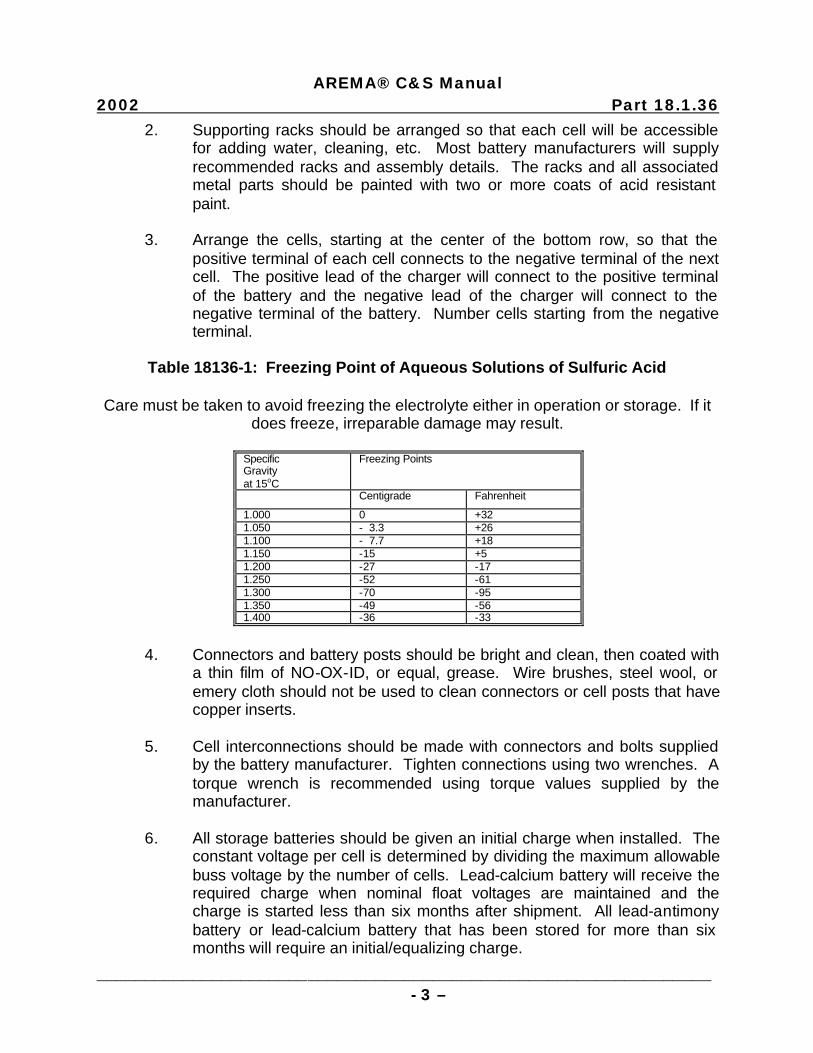
Table 18136-1: Freezing Point of Aqueous Solutions of Sulfuric Acid
Care must be taken to avoid freezing the electrolyte either in operation or storage. If it
does freeze, irreparable damage may result.
Specific Gravity at 15oC
Freezing Points
Centigrade Fahrenheit
1.000 0 +32 1.050 - 3.3 +26 1.100 - 7.7 +18 1.150 -15 +5 1.200 -27 -17 1.250 -52 -61 1.300 -70 -95 1.350 -49 -56 1.400 -36 -33
4. Connectors and battery posts should be bright and clean, then coated with
a thin film of NO-OX-ID, or equal, grease. Wire brushes, steel wool, or emery cloth should not be used to clean connectors or cell posts that have copper inserts.
5. Cell interconnections should be made with connectors and bolts supplied
by the battery manufacturer. Tighten connections using two wrenches. A torque wrench is recommended using torque values supplied by the manufacturer.
6. All storage batteries should be given an initial charge when installed. The
constant voltage per cell is determined by dividing the maximum allowable buss voltage by the number of cells. Lead-calcium battery will receive the required charge when nominal float voltages are maintained and the charge is started less than six months after shipment. All lead-antimony battery or lead-calcium battery that has been stored for more than six months will require an initial/equalizing charge.
AREMA® C&S Manual
Part 18.1.36 2002
________________________________________________________________ - 4 –
7. Dry charged batteries should be installed, filled with electrolyte and receive the initial charge before a load is connected. The higher voltages required for the initial charge may damage equipment if it is connected during the charging period. Remove and discard the vent plug seals before starting the charge.
8. The objective of the initial charge of a dry charged lead-calcium battery is
to establish a charge rate that produces 2.60 to 2.70 volts per cell without exceeding 120°F (49°C) cell temperature. If the constant voltage method is used, connect the charger to a reduced number of cells and charge until the required cell voltage is reached.
The charger connections must then be changed to include the uncharged cells and exclude some of the charged cells. Charging time for each step should be 12 to 16 hr. If a constant current charger is used, the complete battery may be charged at one time. Adjust the charger to the finish rate and charge 12 to 16 hr. Do not exceed 120°F (49°C) or 2.72 volts per cell during either method of charging.
9. Dry charged lead-antimony batteries may be given an initial charge with
either the constant voltage or the constant current method. The charge may be applied to the entire battery at one time. If the constant voltage method is used, the charge time will be slightly longer for a given volts per cell than the initial charge of wet charged battery. If the constant current method is used, adjust the charger to the finish rate and charge for 12 to 16 hr. If cell temperatures reach 120°F (49°C), decrease the charge and increase the time proportionally.
10. When the initial charge of a new battery is completed, record the voltage
and specific gravity of each cell. This information should be kept as part of the permanent record. Specific gravity (corrected to 77°F (25°C)) of all cells should be between 1.200 and 1.220 for nominal 1.210 specific gravity battery.
F. Operation 1. Lead-acid storage batteries are normally operated by float charging or a
combination of float charging and equalizing charges. 2. In float charging the battery is continuously connected in parallel with the
charger and the load. The charger supplies current for the equipment load and in addition supplies enough current to keep the battery fully charged. The voltage at which this occurs is normally called the float voltage. Refer to Tables 18136-2 and 18136-3 for recommended voltages.

AREMA® C&S Manual
2002 Part 18.1.36
________________________________________________________________ - 5 –
3. Equalizing charges are given, at a higher voltage than the float charge, for a definite period of time. Its purpose is to compensate for any irregularities that occur in the battery or individual cells. Refer to Tables 18136-2 and 18136-3 for recommended voltages and time.
4. Lead-antimony batteries require an equalizing charge at least once every
three months. 5. Lead-calcium batteries floated below the nominal volts per cell should be
given an equalizing charge whenever the lowest cell in a string drops to the critical voltage in Table 18136-3. Lead-calcium batteries floated at the nominal volts per cell should not require equalizing charges.
6. Panel voltmeters used during float charging should be kept in accurate
calibration. Check with a known standard at least every twelve months. 7. Any lead-acid storage battery should be recharged as quickly as possible
following an emergency discharge. This can be done by charging the battery at the equalizing voltage until all cells are fully charged.
Table 18136-2: Lead Antimony Cells Charge Voltage Per Cell (VPC)
(1.210 Specific Gravity) Initial Float Equalize VPC Hours VPC VPC 2.39 40 2.15 to 2.17 2.33 for 8 to 2.36 60 24 hr. 2.33 110 2.30 168 2.24 210
Table 18136-3: Lead Calcium Cells Charge Voltage Per Cell (VPC)
Specific Gravity of Cells
Float VPC Initial/Equalize (VPC)
Minimum Nominal Critical Cell Voltage Nominal VPC
1.210 2.17 2.20-2.25 2.13 2.33-2.38 1.225 2.18 2.22-2.27 2.15 2.36-2.40 1.250 2.20 2.25-2.30 2.18 2.38-2.43 1.275 2.23 2.29-2.34 2.20 2.40-2.46 1.300 2.27 2.33-2.38 2.23 2.45-2.50

AREMA® C&S Manual
Part 18.1.36 2002
________________________________________________________________ - 6 –
8. Total discharge of a battery should be avoided if possible. The load should be disconnected when the buss voltage drops below the minimum equipment requirement. If a battery is to be taken out of operation for a period of time, rules for storage should be observed.
9. Connecting loads to only a part of the battery is not recommended. If this
is a requirement, an additional load should be added to the balance of the battery to equalize the cell voltages.
10. The normal battery operating temperature is between
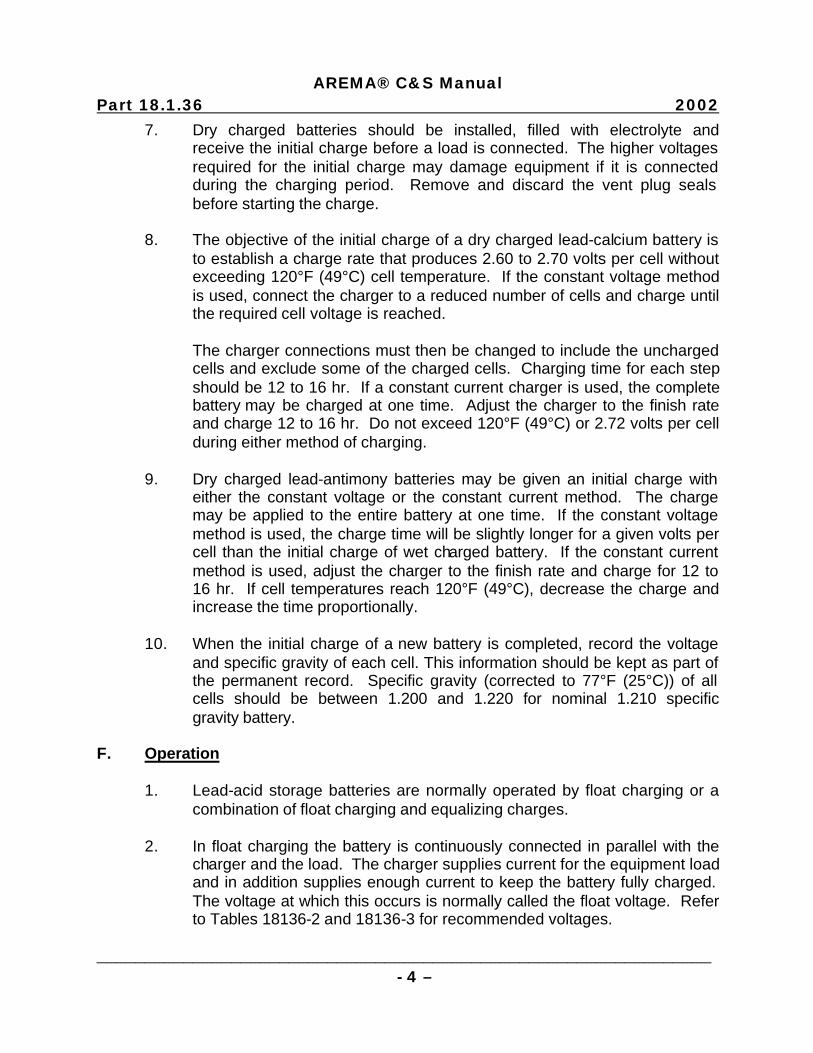
60°F (15°C) and 90°F (32°C) averaging about 75°F (24°C). Higher than normal temperature will:
a. Increase capacity (see Figure 18136-1); b. Increase internal discharge or local action losses; c. Raise charging current for a fixed charge voltage; and d. Shorten battery life.
Lower than normal temperatures will have the opposite effect and decrease the maintenance required.
AREMA® C&S Manual
2002 Part 18.1.36
________________________________________________________________ - 7 –
Figure 18136-1: Battery Capacity vs. Operating Temperature
G. Maintenance 1. Lead-acid storage battery will remain in good condition for many years if
the following rules are observed: a. Maintain the battery fully charged. b. Keep the water level within the recommended limits. c. Keep the battery clean. d. Maintain a record of battery condition and maintenance activity. 2. The state of charge of a battery can be measured by the specific gravity of
the electrolyte. Specific gravity lowers with discharge and rises with charge. The normal reading for a fully charged cell is 1.210 at 77°F (25°C). Some batteries are designed to use electrolyte with specific
AREMA® C&S Manual
Part 18.1.36 2002
________________________________________________________________ - 8 –
gravity other than 1.210. Refer to the manufacturer’s specification or marking on the cells.
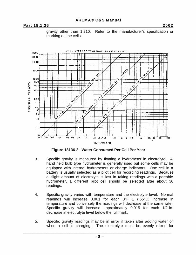
Figure 18136-2: Water Consumed Per Cell Per Year
3. Specific gravity is measured by floating a hydrometer in electrolyte. A
hand held bulb type hydrometer is generally used but some cells may be equipped with internal hydrometers or charge indicators. One cell in a battery is usually selected as a pilot cell for recording readings. Because a slight amount of electrolyte is lost in taking readings with a portable hydrometer, a different pilot cell should be selected after about 30 readings.
4. Specific gravity varies with temperature and the electrolyte level. Normal
readings will increase 0.001 for each 3°F 1 (.65°C) increase in temperature and conversely the readings will decrease at the same rate. Specific gravity will increase approximately 0.015 for each 1/2-in. decrease in electrolyte level below the full mark.
5. Specific gravity readings may be in error if taken after adding water or
when a cell is charging. The electrolyte must be evenly mixed for
AREMA® C&S Manual
2002 Part 18.1.36
________________________________________________________________ - 9 –
accurate readings. After adding water thorough mixing may take several days for lead-antimony cells and up to several weeks for lead-calcium cells. During charge strong acid is released from the plates and falls toward the bottom of the cell where it gradually diffuses through the solution.
6. Water additions are required at various intervals depending upon the type
of battery and the charging rates. Electrolyte should be maintained between the high and low level markings on the cell. Never permit the level of the electrolyte to fall below the top of plate separators. Excessive use of water may indicate over charging. Refer to Figure 18136-2 for normal rates of use.
7. Water used in electrolyte should be distilled or approved water. Battery
manufacturers can provide information or assistance in determining the quality of local water.
8. In temperatures below 0°F (-18°C) water should be added just before an
equalizing charge to insure thorough mixing and prevent freezing. Refer to Table 18136-1.
9. Clean the outside of the cells with a water-moistened cloth to remove dust
and dirt. If electrolyte is spilled on the covers, neutralize it with a cloth moistened with a soda solution, then wipe with a water-moistened cloth. Never use solvents, detergents, cleaning compounds, oils, waxes or polishes on plastic containers.
10. Keep connectors and posts corrosion-free and coated with NO-OX-ID, or
equal, grease. 11. A record of battery operation is a valuable tool in determining equipment
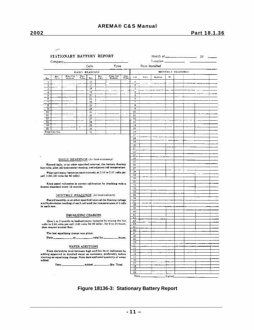
faults, checking maintenance procedures, and indicating when corrective action is necessary. The interval for recording information will vary with location and system routines. A permanent record should start with the initial charge and continue through the life of the battery. A form should be provided to record all the necessary battery readings taken during each recording interval. Refer to Figure 18136-3.
H. Battery Record 1. The following information should be recorded: a. Date and description of last equalizing charge (if battery is lead-
antimony).
AREMA® C&S Manual
Part 18.1.36 2002
________________________________________________________________ - 10 –
b. Battery floating voltage; pilot cell hydrometer reading and temperature, once weekly or as often as an unattended site is visited.
c. Individual cell voltages to the nearest hundredth of a volt, once a
month. d. Individual cell specific gravities and temperature of the highest and
lowest cell, once every three months. e. Water additions when required.
These intervals are typical. The battery manufacturer may recommend other intervals according to the type of battery or service.
2. Call voltages should be read while the normal charging current is being
maintained. Specific gravity readings should not be taken while a battery is on a high rate of charge.
3. A continuing decline in specific gravity of the pilot cell indicates insufficient
charge caused by low float voltage. When floating charge is correct the hydrometer reading will stay close to the maximum value for the cell.
4. If a particular cell or group of cells shows lower than normal readings the
cause may be uneven temperatures or internal cell troubles. Contamination of electrolyte can cause cell troubles.
I. Spent Batteries 1. Spent batteries shall be handled in accordance with Manual Part 9.5.5
(Recommended Instructions for Disposal and Recycling of Batteries).
AREMA® C&S Manual
2002 Part 18.1.36
________________________________________________________________ - 11 –
Figure 18136-3: Stationary Battery Report
20

This page intentionally left blank

AMERICAN RAILWAY ENGINEERING AND MAINTENANCE OF WAY ASSOCIATION
COMMUNICATIONS & SIGNALS MANUAL
Section 19 – Electrical Protection
2002

This page intentionally left blank
AREMA® C&S Manual 2002 (Includes 2002 Revisions) Volume 5 Index SECTION 19 - ELECTRICAL PROTECTION Part C Type & Subject Pages Status
______________________________________________________________- 1 -
Note: C = Committee responsible for Manual Part.
19.1.10 35-1 Recommended Functional/ Operating Guidelines for Surge Protectors That Operate to Ground 2 Reaffirmed 1989 19.1.14 35-1 Recommended Practices for Installation and Maintenance of Grounds for Communication Facilities 9 Revised 1995 19.1.20 35-2 Recommendations for an Electrostatic Discharge (ESD) Control Program 16 New 1994

This page intentionally left blank
- 1 – AREMA C&S Manual
1989 Part 19.1.10
Recommended Functional/Operating Guidelines for Surge Protectors That Operate to Ground Reaffirmed 1989 (2 Pages) A. These recommended functional/operating guidelines are for
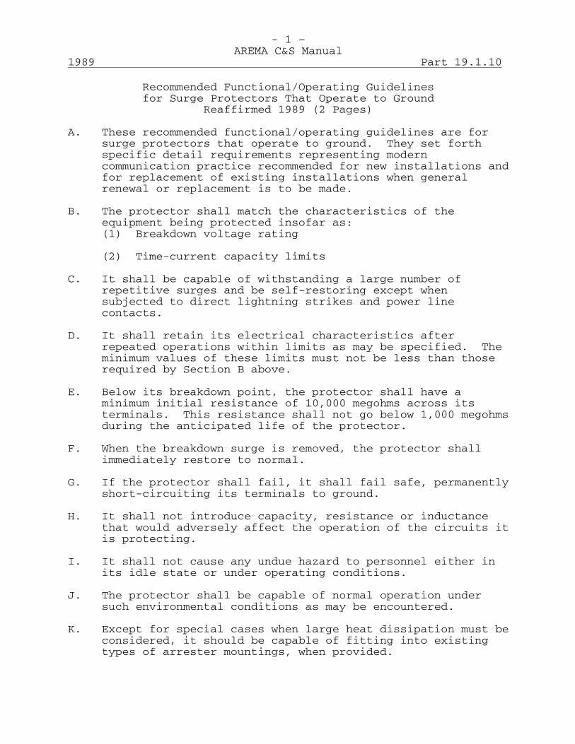
surge protectors that operate to ground. They set forth specific detail requirements representing modern communication practice recommended for new installations and for replacement of existing installations when general renewal or replacement is to be made.
B. The protector shall match the characteristics of the
equipment being protected insofar as: (1) Breakdown voltage rating (2) Time-current capacity limits C. It shall be capable of withstanding a large number of
repetitive surges and be self-restoring except when subjected to direct lightning strikes and power line contacts.
D. It shall retain its electrical characteristics after
repeated operations within limits as may be specified. The minimum values of these limits must not be less than those required by Section B above.
E. Below its breakdown point, the protector shall have a
minimum initial resistance of 10,000 megohms across its terminals. This resistance shall not go below 1,000 megohms during the anticipated life of the protector.
F. When the breakdown surge is removed, the protector shall
immediately restore to normal. G. If the protector shall fail, it shall fail safe, permanently
short-circuiting its terminals to ground. H. It shall not introduce capacity, resistance or inductance
that would adversely affect the operation of the circuits it is protecting.
I. It shall not cause any undue hazard to personnel either in
its idle state or under operating conditions. J. The protector shall be capable of normal operation under
such environmental conditions as may be encountered. K. Except for special cases when large heat dissipation must be
considered, it should be capable of fitting into existing types of arrester mountings, when provided.
- 2 – AREMA C&S Manual
Part 19.1.10 1989
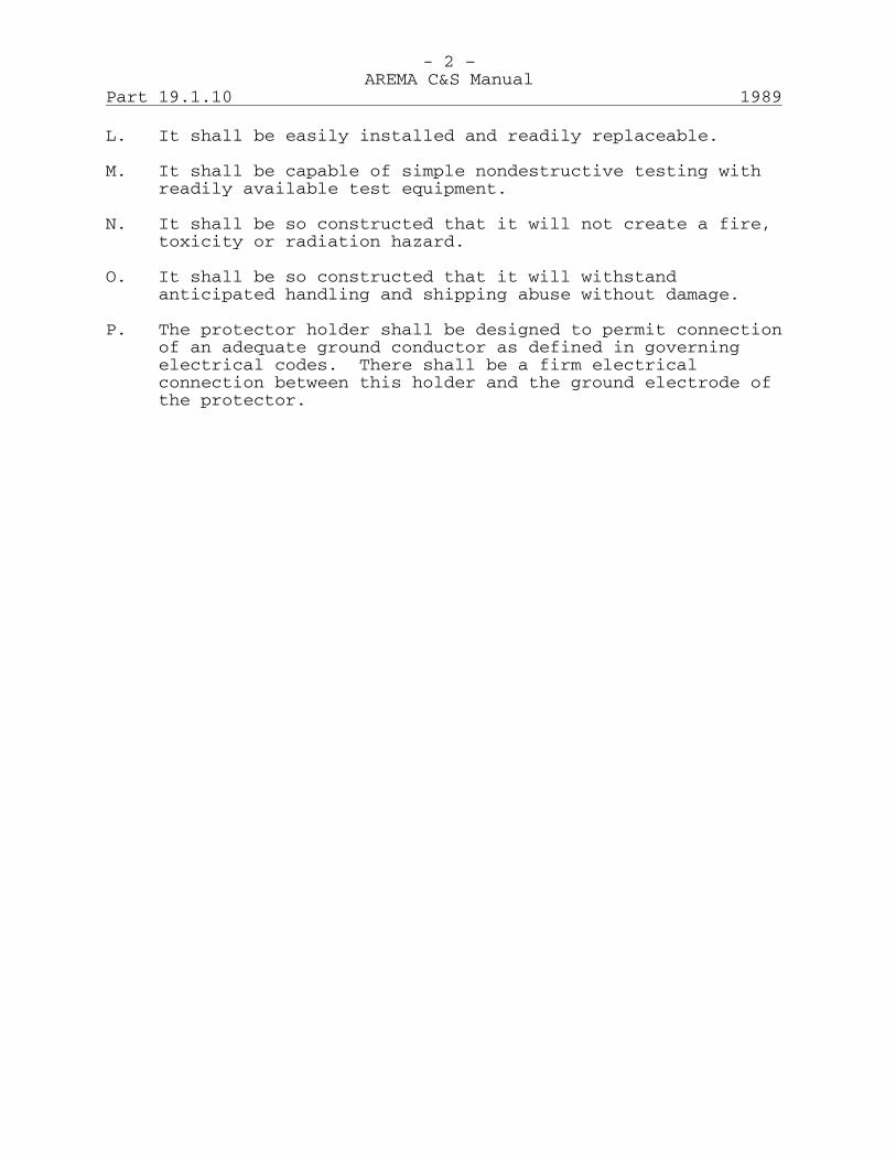
L. It shall be easily installed and readily replaceable. M. It shall be capable of simple nondestructive testing with
readily available test equipment. N. It shall be so constructed that it will not create a fire,
toxicity or radiation hazard. O. It shall be so constructed that it will withstand
anticipated handling and shipping abuse without damage. P. The protector holder shall be designed to permit connection
of an adequate ground conductor as defined in governing electrical codes. There shall be a firm electrical connection between this holder and the ground electrode of the protector.
- 1 – AREMA C&S Manual
1995 Part 19.1.14
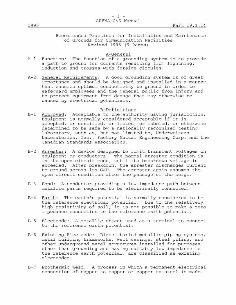
Recommended Practices for Installation and Maintenance of Grounds for Communication Facilities Revised 1995 (9 Pages) A-General A-1 Function: The function of a grounding system is to provide
a path to ground for currents resulting from lightning, induction and crosses with foreign circuits.
A-2 General Requirements: A good grounding system is of great
importance and should be designed and installed in a manner that ensures optimum conductivity to ground in order to safeguard employees and the general public from injury and to protect equipment from damage that may otherwise be caused by electrical potentials.
B-Definitions B-1 Approved: Acceptable to the authority having jurisdiction.
Equipment is normally considered acceptable if it is accepted, or certified, or listed, or labeled, or otherwise determined to be safe by a nationally recognized testing laboratory, such as, but not limited to, Underwriters Laboratories, Inc., Factory Mutual Engineering Corp. and the Canadian Standards Association.
B-2 Arrester: A device designed to limit transient voltages on
equipment or conductors. The normal arrester condition is in the open circuit mode, until its breakdown voltage is exceeded. After breakdown, the arrester discharges current to ground across its GAP. The arrester again assumes the open circuit condition after the passage of the surge.
B-3 Bond: A conductor providing a low impedance path between
metallic parts required to be electrically connected. B-4 Earth: The earth's potential is normally considered to be
the reference electrical potential. Due to the relatively high resistivity of soil, it is not possible to make a zero impedance connection to the reference earth potential.
B-5 Electrode: A metallic object used as a terminal to connect
to the reference earth potential. B-6 Existing Electrode: Direct buried metallic piping systems,
metal building frameworks, well casings, steel piling, and other underground metal structures installed for purposes other than grounding and having suitably low impedance to the reference earth potential, are classified as existing electrodes.
B-7 Exothermic Weld: A process in which a permanent electrical
connection of copper to copper or copper to steel is made.
- 2 – AREMA C&S Manual
Part 19.1.14 1995
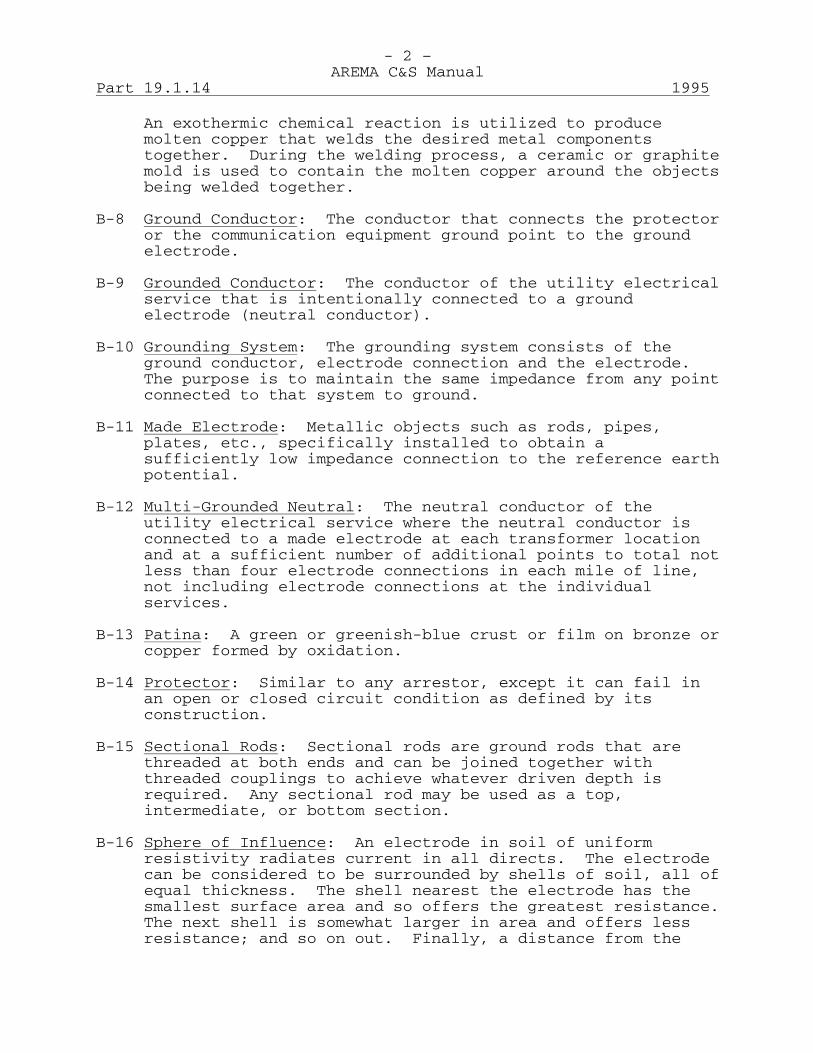
An exothermic chemical reaction is utilized to produce molten copper that welds the desired metal components together. During the welding process, a ceramic or graphite mold is used to contain the molten copper around the objects being welded together.
B-8 Ground Conductor: The conductor that connects the protector
or the communication equipment ground point to the ground electrode.
B-9 Grounded Conductor: The conductor of the utility electrical
service that is intentionally connected to a ground electrode (neutral conductor).
B-10 Grounding System: The grounding system consists of the
ground conductor, electrode connection and the electrode. The purpose is to maintain the same impedance from any point connected to that system to ground.
B-11 Made Electrode: Metallic objects such as rods, pipes,
plates, etc., specifically installed to obtain a sufficiently low impedance connection to the reference earth potential.
B-12 Multi-Grounded Neutral: The neutral conductor of the
utility electrical service where the neutral conductor is connected to a made electrode at each transformer location and at a sufficient number of additional points to total not less than four electrode connections in each mile of line, not including electrode connections at the individual services.
B-13 Patina: A green or greenish-blue crust or film on bronze or
copper formed by oxidation. B-14 Protector: Similar to any arrestor, except it can fail in
an open or closed circuit condition as defined by its construction.
B-15 Sectional Rods: Sectional rods are ground rods that are
threaded at both ends and can be joined together with threaded couplings to achieve whatever driven depth is required. Any sectional rod may be used as a top, intermediate, or bottom section.
B-16 Sphere of Influence: An electrode in soil of uniform
resistivity radiates current in all directs. The electrode can be considered to be surrounded by shells of soil, all of equal thickness. The shell nearest the electrode has the smallest surface area and so offers the greatest resistance. The next shell is somewhat larger in area and offers less resistance; and so on out. Finally, a distance from the

- 3 – AREMA C&S Manual
1995 Part 19.1.14
electrode is reached where an additional shell of soil will not add significantly to the total resistance. This is the dimension of the sphere of influence of the electrode. For a ground rod or pipe, the radius of the sphere of influence can usually be considered to be equal to the driven depth of the rod or pipe.
C-Choice of Electrodes C-1 Existing Electrodes: An extensive direct buried metallic
cold water piping system is the preferred electrode where it is readily accessible. Such systems normally have a resistance to earth within the maximum values given in Table II and have been used extensively in the past.
C-2 A direct buried cold water piping system with nonmetallic
pipe, corrosion protected metallic pipe, or metallic pipe with insulated joints is not suitable for use as a grounding electrode.
C-3 Insulated or non-insulated underground cold water piping
connected to a well that has a measured resistance to earth within the maximum values given in Table 2, may be used as a grounding electrode. Care must be exercised to assure that all parts of the piping system that may be disconnected at some time in the future are effectively bonded together.
C-4 Direct buried metallic piping systems other than for cold
water (steam pipes, gas pipes, sprinkler systems, air lines, etc.) shall not be used as a grounding electrode.
C-5 Made Electrodes: Where a suitable existing electrode is not
available or where it is desired to have a supplemental electrode, a made electrode must be installed.
C-6 Made electrodes shall be of metal or combinations of metals
that do not corrode excessively under the existing conditions for the expected service life of the communication installation. All outer surfaces of a made electrode shall be conductive, that is, not having paint, enamel, or other insulating type covering.
C-7 Made electrodes shall, as far as practical, penetrate below
the frost line and into permanent moisture level. Failure to reach permanent moisture may not only result in high resistance to earth, but may also result in large variations in resistance during changes of the seasons.
C-8 Made electrodes may consist of driven rods, driven pipes,
buried wire, buried plates, or buried strips of metal. Driven rods are the most generally used and are the recommended type of made electrode.
- 4 – AREMA C&S Manual
Part 19.1.14 1995
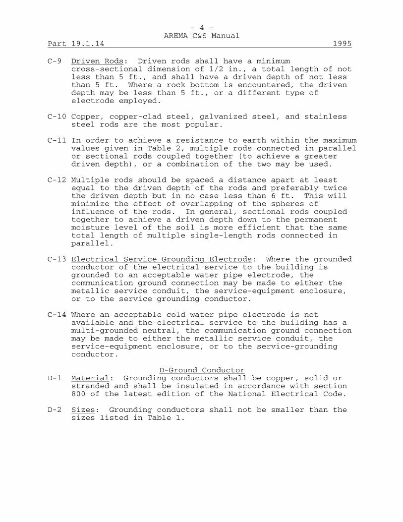
C-9 Driven Rods: Driven rods shall have a minimum cross-sectional dimension of 1/2 in., a total length of not less than 5 ft., and shall have a driven depth of not less than 5 ft. Where a rock bottom is encountered, the driven depth may be less than 5 ft., or a different type of electrode employed.
C-10 Copper, copper-clad steel, galvanized steel, and stainless
steel rods are the most popular. C-11 In order to achieve a resistance to earth within the maximum
values given in Table 2, multiple rods connected in parallel or sectional rods coupled together (to achieve a greater driven depth), or a combination of the two may be used.
C-12 Multiple rods should be spaced a distance apart at least
equal to the driven depth of the rods and preferably twice the driven depth but in no case less than 6 ft. This will minimize the effect of overlapping of the spheres of influence of the rods. In general, sectional rods coupled together to achieve a driven depth down to the permanent moisture level of the soil is more efficient that the same total length of multiple single-length rods connected in parallel.
C-13 Electrical Service Grounding Electrods: Where the grounded
conductor of the electrical service to the building is grounded to an acceptable water pipe electrode, the communication ground connection may be made to either the metallic service conduit, the service-equipment enclosure, or to the service grounding conductor.
C-14 Where an acceptable cold water pipe electrode is not
available and the electrical service to the building has a multi-grounded neutral, the communication ground connection may be made to either the metallic service conduit, the service-equipment enclosure, or to the service-grounding conductor.
D-Ground Conductor D-1 Material: Grounding conductors shall be copper, solid or
stranded and shall be insulated in accordance with section 800 of the latest edition of the National Electrical Code.
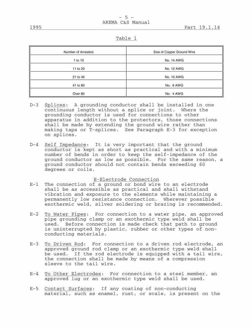
D-2 Sizes: Grounding conductors shall not be smaller than the
sizes listed in Table 1.
- 5 – AREMA C&S Manual
1995 Part 19.1.14
Table 1
Number of Arresters Size of Copper Ground Wire
1 to 10 No. 14 AWG
11 to 20 No. 12 AWG
21 to 40 No. 10 AWG
41 to 80 No. 6 AWG
Over 80 No. 4 AWG
D-3 Splices: A grounding conductor shall be installed in one
continuous length without a splice or joint. Where the grounding conductor is used for connections to other apparatus in addition to the protectors, those connections shall be made by extending the ground wire rather than making taps or T-splices. See Paragraph E-3 for exception on splices.
D-4 Self Impedance: It is very important that the ground
conductor is kept as short as practical and with a minimum number of bends in order to keep the self-impedance of the ground conductor as low as possible. For the same reason, a ground conductor should not contain bends exceeding 60 degrees or coils.
E-Electrode Connection E-1 The connection of a ground or bond wire to an electrode
shall be as accessible as practical and shall withstand vibration and exposure to the elements while maintaining a permanently low resistance connection. Wherever possible exothermic weld, silver soldering or brazing is recommended.
E-2 To Water Pipes: For connection to a water pipe, an approved
pipe grounding clamp or an exothermic type weld shall be used. Before connection is made check that path to ground is uninterrupted by plastic, rubber or other types of non-conducting materials.
E-3 To Driven Rod: For connection to a driven rod electrode, an
approved ground rod clamp or an exothermic type weld shall be used. If the rod electrode is equipped with a tail wire, the connection shall be made by means of a compression sleeve to the tail wire.
E-4 To Other Electrodes: For connection to a steel member, an
approved lug or an exothermic type weld shall be used. E-5 Contact Surfaces: If any coating of non-conducting
material, such as enamel, rust, or scale, is present on the
- 6 – AREMA C&S Manual
Part 19.1.14 1995
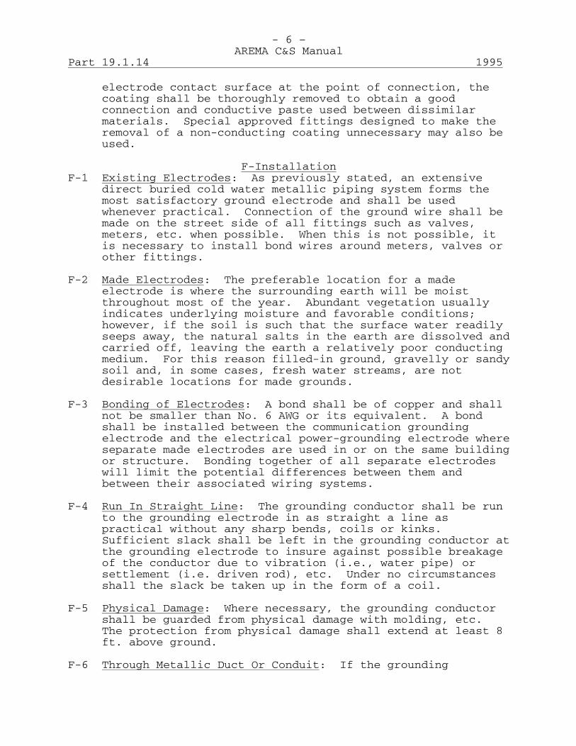
electrode contact surface at the point of connection, the coating shall be thoroughly removed to obtain a good connection and conductive paste used between dissimilar materials. Special approved fittings designed to make the removal of a non-conducting coating unnecessary may also be used.
F-Installation F-1 Existing Electrodes: As previously stated, an extensive
direct buried cold water metallic piping system forms the most satisfactory ground electrode and shall be used whenever practical. Connection of the ground wire shall be made on the street side of all fittings such as valves, meters, etc. when possible. When this is not possible, it is necessary to install bond wires around meters, valves or other fittings.
F-2 Made Electrodes: The preferable location for a made
electrode is where the surrounding earth will be moist throughout most of the year. Abundant vegetation usually indicates underlying moisture and favorable conditions; however, if the soil is such that the surface water readily seeps away, the natural salts in the earth are dissolved and carried off, leaving the earth a relatively poor conducting medium. For this reason filled-in ground, gravelly or sandy soil and, in some cases, fresh water streams, are not desirable locations for made grounds.
F-3 Bonding of Electrodes: A bond shall be of copper and shall
not be smaller than No. 6 AWG or its equivalent. A bond shall be installed between the communication grounding electrode and the electrical power-grounding electrode where separate made electrodes are used in or on the same building or structure. Bonding together of all separate electrodes will limit the potential differences between them and between their associated wiring systems.
F-4 Run In Straight Line: The grounding conductor shall be run
to the grounding electrode in as straight a line as practical without any sharp bends, coils or kinks. Sufficient slack shall be left in the grounding conductor at the grounding electrode to insure against possible breakage of the conductor due to vibration (i.e., water pipe) or settlement (i.e. driven rod), etc. Under no circumstances shall the slack be taken up in the form of a coil.
F-5 Physical Damage: Where necessary, the grounding conductor
shall be guarded from physical damage with molding, etc. The protection from physical damage shall extend at least 8 ft. above ground.
F-6 Through Metallic Duct Or Conduit: If the grounding

- 7 – AREMA C&S Manual
1995 Part 19.1.14
conductor is run through a metallic duct or conduit it must be bonded to each end of the duct or conduit.
F-7 Splices: See Paragraph D-3. G-Resistance to Earth G-1 The grounding electrode system may consist of one or more
electrodes bonded together. The resistance to earth of the grounding electrode system shall not exceed the values given in Table II under ordinary conditions. If a particular situation dictates, a lower resistance may be required.
Table 2
Plant for Which Ground is Provided Maximum Allowable Resistance
Offices with power facilities or with suitable
water pipe ground.
10 ohms
Offices with made ground and with protectors
for over 10 wires.
25 ohms
All other offices. 50 ohms
Booths and shelter boxes. 75 ohms
Cable terminals (except where cable sheath
ground is used) and grounds for messages.
100 ohms
H-Measurement of Electrode Resistance H-1 In general, experience in any given location will enable an
installer to determine whether or not an existing electrode will have a resistance within the limits given in Table II or what type and configuration of made electrode will be required. It is recommended, however, that the resistance of an existing electrode, as well as a made electrode, should be measured before it is placed in service.
H-2 The resistance to earth of a made electrode may vary
considerably from time to time due to the amount of moisture contained in the earth. Therefore, measurements of electrode resistance to ground should not be made during those times when the moisture content of the earth is greater than normal.
H-3 The resistance of an electrode to earth may be easily
measured by using a direct reading instrument specifically designed for this purpose. This type of instrument permits the resistance to be measured with a minimum amount of time and effort. It is strongly recommended that an instrument specifically designed for measurement of electrode
resistance to earth should be used rather than using instruments designed for other purposes.
- 8 – AREMA C&S Manual
Part 19.1.14 1995
H-4 The electrode under test should be isolated from the grounded equipment during the measurement procedure in order to obtain an accurate resistance measurement. Preferably, the ground conductor should be disconnected from the electrode. This temporary disconnection of the ground conductor shall be permitted only under competent supervision and for testing purposes only.
H-5 There are two methods generally used to measure the
electrode resistance to earth. The two terminal method, also known as the direct method, and the three terminal method, also known as the fall-of-potential method.
H-6 Two Terminal Method: This is the simplest method but it can
be used only if certain requirements are met. First, an existing electrode of known low resistance to earth (such as an extensive direct buried metallic cold water piping system) must be available. Second, the electrode under test must not be in the sphere of influence of the existing reference electrode. The instrument is connected to each electrode and measures the sum of the resistances to earth of the two electrodes. The resistance to ground of the electrode under test is obtained by subtracting the resistance to ground of the known electrode from the measured resistance.
H-7 Three Terminal Method: In the three terminal method, two
small test probes, which are part of the test instrument, are used in conjunction with the electrode under test. A reference electrode is, therefore, not required. Consult the instructions with the particular test instrument being used for information on performing this measurement.
H-8 When using either the two terminal method or the three
terminal method, care should be exercised to avoid influence of the test readings by any stray ground currents or buried metallic pipes, etc.
J-Reducing Resistance of Made Electrodes J-1 Chemical Soil Treatment: When deep driven rods are not
possible due to hard underlying rock, etc., and the number of multiple paralleled rods required make this approach impractical, then chemical treatment may be required. Chemical treatment of the soil around a ground rod reduces the resistivity of the soil and, therefore, the resistance of the ground rod to earth. Chemical treatment is also beneficial in reducing seasonal variations in resistance due to periodic wetting and drying out of the soil.
J-2 There are several methods used in chemical soil treatment
including the trench method and the basin method.

- 9 – AREMA C&S Manual
1995 Part 19.1.14
J-3 Trench Method: In the trench method, a donut shaped trench is dug around the ground rod with a depth of about 12 in. The chemical is poured into the trench and covered with a layer of soil. This method eliminates direct contact of the chemical with the rod.
J-4 Container Method: In the container method, a tile pipe
about 16 in. long and 8 in. in diameter (or other suitable open ended container) is buried 4 to 6 in. from the ground rod. The container is filled with a chemical and covered. The chemical slowly washes into the soil near the electrode. This method does not treat the soil as fast as the trench method but is has a longer interval between treatments.
J-5 Chemicals: The most generally used chemicals are magnesium
sulfate, copper sulfate and ordinary rock salt. J-6 Treatment Intervals: Chemical treatment is not permanent
because the chemical is gradually washed away by rainfall and natural drainage through the soil. Depending on local conditions, the interval between treatments varies but may be up to several years long.
K-Maintenance K-1 Inspection and Tests: Inspections and tests should be made
at regular intervals, as determined by past experience with grounding systems in a particular area, to insure that the grounding system meets the requirements of this specification. Records should be kept so that a general trend of increased ground resistance will be evident.
K-2 All joints and connections should be periodically inspected.
If found faulty, repairs shall be made as required. K-3 A green film called a patina may form on copper ground
conductors and electrodes due to the unavoidable corrosion process. This patina should not be cleaned off because it slows down the process of corrosion, even though it was originally caused by corrosion.
L-References L-1 Reference was made to the following codes and standards in
the preparation of this recommend practice. American National Standard Institute National Electrical Safety Code, ANSI C2-1981 National Electrical Code, NFPA 70-1981 Canadian Electrical Code, C22.1-1982

This page intentionally left blank
- 1 – AREMA C&S Manual
1994 Part 19.1.20
Recommendations for an Electrostatic Discharge (ESD) Control Program New 1994 (16 Pages) A. Purpose The purpose of an ESD control program is to provide
electronic assemblies and components with continuous protection from ESD.
B. General 1. Static damage can result in destruction or catastrophic
failure when high voltage and instantaneous current flow cause the melting of metallic oxide and other components.
2. Static damage can cause life degradation or latent
defects. 3. Intermittent failures can occur when transient induced
current and polarization cause a device to fail intermittently. This type of damage is very difficult to detect.
4. In order to prevent static damage to electronic parts
and assemblies, a railroad should establish and enforce an ESD control policy that includes the following six steps:
(a) Insure that vendors provide ESD protection during
manufacture and shipment. (b) Insure that all ESD sensitive items are marked
with an ESD caution label. (c) Provide appropriate instructions for personnel who
will be handling ESD sensitive items. (d) Transport ESD sensitive items only in appropriate
packaging. (e) Open ESD protective packaging only in ESD
protected conditions (f) Insure that the ESD protection is functioning
properly. 5. Definition of Terms ESD: Electrostatic Discharge, a sudden redistribution
of static charge that is damaging to sensitive components.

- 2 – AREMA C&S Manual
Part 19.1.20 1994
ESD-Sensitive (ESDS): A part, assembly or product that can be degraded or damaged by ESD. There are ESDS parts in nearly every family of electronic components containing thin films or insulators, including resistors, capacitors and semiconductor devices. All unmarked components or assemblies and all Class 0, Class 1, and Class 2 devices should be considered as ESDS parts. See Part Classification Table 1.
ESD Controlled Area: A specifically designated area
that has been properly marked and equipped for handling ESD-Sensitive assemblies and components. ESDS parts should only be removed from ESD packaging in an ESD Controlled Area.
Triboelectricity: The transfer of charge by contact and
separation of two surfaces. This charging by "rubbing or separating" is a common source of static charges.
Antistatic: A material that resists triboelectric
charging and produces a static voltage of less than 100 volts when rubbed against itself or another material. A material's antistatic property is not necessarily correlated with its resistivity, and can be degraded by factors such as age, wear, contamination, solvents and climate.
Conductive: A material with surface resistivity less
than 100,000 ohms per square and volume resistivity less than 10,000 ohm-cm (Per mil HDBK-263A), generally achieved by means of coating or impregnating with carbon or metal. Conductive materials are not necessarily antistatic. A static-shielding enclosure ("Faraday Cage") requires conductive materials.
Dissipative: A material with surface resistivity from
100,000 ohms to 1,000,000,000,000 ohms per square and volume resistivity between 10,000 ohm-cm and 100,000,000,000 ohm-cm (Per mil HDBK-263A).
Static Shield: A conductive surface that terminates all
the static field lines that intersect it. A Faraday Cage is a static shield formed into a closed container. This is the best form of protection for ESDS items that may be transported or stored in static-unsafe areas.
Reuse: To use a product more than one time without
altering its physical construction. Inspecting, and relabeling are permitted within the definition of reuse.
- 3 – AREMA C&S Manual
1994 Part 19.1.20
C. Part Classification (ESD) The part supplier shall establish, and furnish upon
request, the level of susceptibility to ESD for each individual part, family or assembly per the following classes (per MIL-STD-1686) based on Human Body Model:
Table 1 CLASS 0 0 - 200 V CLASS 1 0 - 1999 V CLASS 2 2000 - 3999 V CLASS 3 4000 - 15,999 V Unless otherwise stated all ESDS Parts should be
treated as Class 1 for the level of susceptibility to ESD damage.
D. Responsibility 1. An individual should be designated who is responsible
for the implementation and administration of the ESD control program. ESD coordinators should be designated in each work area where the guidelines are to be enforced. The ESD coordinator is responsible for yearly and monthly ESD Audits. Appendix A provides a sample ESD Audit Form.
2. All employees should join in the enforcement of these
policies by bringing any deficiencies to the attention of their manager or the ESD coordinator.
3. Employees are responsible for escorting and assuring
that ALL VISITORS adhere to the ESD guidelines, and should report when visitors are coming into ESD protected areas to the ESD Coordinator.
E. Training All personnel who come in contact, or may come in contact
with static sensitive parts, shall have instruction in the safe handling of those items. These instructions should enable personnel to meet the requirements of this policy. Approved ESD protection instructions will be provided by the ESD coordinator.
F. Labeling Recommendations 1. ESD Symbols (a) Recommended Symbol: The recommended symbol for
ESDS devices is defined by EIA-471 (Figure 1). It consists of a triangle enclosing a hand, crossed by a diagonal slash, and the words "ATTENTION, OBSERVE PRECAUTIONS FOR HANDLING ELECTROSTATIC SENSITIVE DEVICES". The colors are not specified,
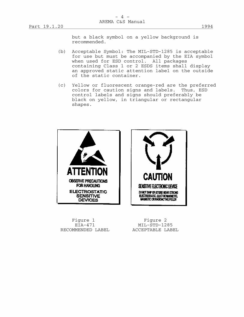
- 4 – AREMA C&S Manual
Part 19.1.20 1994
but a black symbol on a yellow background is recommended.
(b) Acceptable Symbol: The MIL-STD-1285 is acceptable
for use but must be accompanied by the EIA symbol when used for ESD control. All packages containing Class 1 or 2 ESDS items shall display an approved static attention label on the outside of the static container.
(c) Yellow or fluorescent orange-red are the preferred
colors for caution signs and labels. Thus, ESD control labels and signs should preferably be black on yellow, in triangular or rectangular shapes.
Figure 1 Figure 2 EIA-471 MIL-STD-1285 RECOMMENDED LABEL ACCEPTABLE LABEL
- 5 – AREMA C&S Manual
1994 Part 19.1.20
G. Handling Requirements 1. Packaging (a) All electrostatic sensitive parts shall be
protected from electrostatic discharge by protective packaging.
- All electrostatic packages containing
electrostatic sensitive parts must be labeled with an appropriate ESD Caution label.
- Circuit assemblies and components are only
protected when completely enclosed inside an antistatic protective environment such translucent static shielded bag, pink or blue poly antistatic bag, or black conductive container.
(b) Sensitive parts shall be shipped from the
manufacturer in electrostatic protective packaging and labeled with an ESD label. These parts shall remain in that packaging continuously except when actually at a static free workstation.
(c) Circuit assemblies shall be placed in static
shielded bags or conductive containers for transportation or storage.
2. Workstations (a) Workstations used for handling sensitive parts
must be equipped with static free work surfaces and floor mats. These surfaces and mats must be static dissipative and grounded to a true earth ground.
(b) All electrical equipment used at static free
workstations must be grounded. Soldering irons shall be of an approved ESD protected design.
(c) Workstation chairs or stools must be grounded in
one of two ways: carbon filled conductive casters or brass drag chains attached to the center of the chair base. These chairs or stools must be used in conjunction with static free floor mats.
(d) No plastic materials shall be allowed within three
feet of static free workstations. This includes candy wrappers, tape, cigarette packages, cellophane wrappers, foam cups, foam packaging (peanuts), bubble wrap, plastic bins, plastic folders, etc.
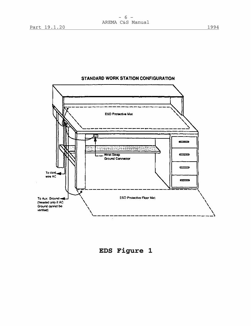
- 6 – AREMA C&S Manual
Part 19.1.20 1994
EDS Figure 1

- 7 – AREMA C&S Manual
1994 Part 19.1.20
(e) Temperature and humidity monitors should be installed in ESD safe areas and are to be monitored by personnel in each area for humidity levels. Humidity levels that reach 25% or less should be reported to the ESD coordinator, as these levels present possible ESD problems.
3. Personnel (a) The wrist strap must be worn in direct contact
with the bare skin. Personnel shall not be attached directly to an earth ground. There must be a safety 250k Ohm to 1 Meg Ohm resistance between the operator and the ground (these resistors have been molded into the ground cords of some ESD mats).
(b) All personnel within three feet of a static free
work station must be grounded with a wrist strap and ground cord attached to the grounded work surface.
(c) The wrist strap shall be functionally checked by
the user daily. Testers should be placed in all ESD protected areas for this purpose. Equipment is also available to continuously monitor the wrist strap.
(d) Improperly grounded or ungrounded personnel shall
never touch static sensitive parts, assemblies, or other operators at a static free work station.
4. Equipment locations (a) A railroad may elect to place properly grounded
floor mats on floors where access is made to any system using plug in cards with ESDS components. This should include microwave equipment, electronic switchboards, packet switches, rack mounted data modems or multiplexers, radio base stations, and other electronic equipment.
(b) A properly grounded wrist strap should be attached
to the equipment rack. (c) Alternatively, a portable service kit containing
ESD mat and wrist strap can be used when servicing installed equipment.
H. Maintenance of Static Protective Equipment 1. Workstation Mats The surface of mats must be cleaned with an antistatic
- 8 – AREMA C&S Manual
Part 19.1.20 1994
cleaner, monthly, or more often as required, to prevent contamination from dirt, grime, solder, body oils, dust particles, etc.
2. Wrist Bands Wrist bands may be laundered, using a mild detergent -
no bleach, as required to prevent body oils from compromising the electrical functionality of the material. Care must be taken to place the band in a pocket to keep it from becoming entangled in the agitator of the washing machine.
3. Smocks (Lab Coats) (a) All personnel are to wear conductive smocks while
working on Static Sensitive components or assemblies.
(b) All other personnel including visitors are to wear
conductive smocks while working in or touring the ESD Protected Area.
(c) Smocks may be laundered, using a mild detergent -
no bleach, by the user at home, or by an approved garment laundering agency.
I. Maintenance Shop Area, Warehouse, and Staging Areas 1. The ESD Protected Area floor should have an anti-static
surface applied to it. Facility maintenance will maintain the floor on the following schedule:
- weekly - anti-static wax to be applied to
surfaces where required. - yearly - floor to be stripped and retreated. 2. Areas designated as a Static Safeguarded Work Area are
marked by ESD signs informing personnel of the ESD Policy and by a yellow band on the floor defining the perimeter of the area.
J. Electrical Tests 1. Specialized test equipment can be used to routinely
verify proper electrical performance of the wrist strap. Follow the manufacturer's instructions to verify wrist strap performance.
2. Equipment is available to continuously monitor the
performance of the wrist strap and grounding. Follow the manufacturer's instructions to continuously verify wrist strap performance.
- 9 – AREMA C&S Manual
1994 Part 19.1.20
3. The bench/table and floor mats should be tested by a qualified ESD auditor.
K. Frequency of Testing Wrist Straps - Daily - (personnel not required to
use wrist straps daily, must test them before each use)
Table/Floor Mats - Monthly by ESD Coordinator, Yearly
by Quality Assurance Mat Ground Cords - Daily by Operators, Monthly by ESD
Coordinator, Yearly by Quality Assurance
Ground/Connection - Daily by Operators Static Shielded - As Required. At the minimum Bags Yearly Ionizers - Yearly or as determined by the
Calibration Dept. L. ESD Program Supplies This section provides a listing of items that may be needed
for a successful ESD control program. Antistatic Cleaner Antistatic Storage Cabinet Conductive Storage Drawers Conductive Smock (Lab Coat) Conductive Tool Box ESD Floor Mat ESD Video Tapes ESD Packaging ESD Heel Strap Field Service Ground Kit Ground Cords Ionizer Outlet Tester Portable Static Meter Static Shielding Work Surfaces Static Shielding Work Surface Tester Static Shielding Floor Finish (Antistatic Wax) Static Shielding Floor Surfaces Warning Labels Wrist Strap Wrist Strap Tester M. Sources This section provides a partial listing of possible sources
for the ESD program supplies identified in Section J.
- 10 – AREMA C&S Manual
Part 19.1.20 1994
Atrix, Inc., 14301 Ewing South, Burnsville, MN. 55337. Phone (800) 222-6154.
Baxter Healthcare Corp., Scientific Products Division, 1210
Waukegan Road, McGraw Park, IL. 60085. Phone (708) 689-8410 Charles Walters, 93 Border Street, West Newton, MA. 02165.
Phone (617) 964-8370. Contact East, 335 Willow Street South, North Andover, MA.
01845-5995. Phone (508) 682-2000. HYMAR Meters, 6647 Blossom Acres Drive, San Jose, CA. 95124.
Phone (408) 358-6280. JULIE Associates, P.O. Box 141, Billerica, MA. 01821. Phone
(508) 667-1958. Motorola C&E Inc., Communications Parts Division, 1313 E.
Algonquin Road, Schaumburg, IL. 60196. Phone (708) 576-6485.
Static Control Components, Inc., P.O. Box 152, Stanford, NC.
27331. Phone (800) 356-2728. Static Control Systems Division/3M, P.O. Box 2963, Austin,
TX. 78769-6154. Phone (800) 222-6154. Westcorp, 144 S. Whisman Road, Mountain View, CA. 94041.
Phone (800) 537-7828. N. References 1. MIL-STD-1686A - Electrostatic Discharge Control Program
for Protection of Electrical and Electronic Parts, Assemblies and Equipment
2. MIL-HDBK-263, Electrostatic Discharge Control Handbook. 3. AMCI Electrostatic Discharge Control Policy, M07093,
Revision C, October 14, 1993, Automated Monitoring and Control International, 11819 Miami, Omaha, NE 68164.
4. A sample of a more detailed Packaging and Handling
Specification, ESD control policy is available from 3M Company, Electrical Specialties Division, P.O. Box 33211, St. Paul, MN 55133-3211
5. A videotape (F.A.S.T. #5) on electrostatic discharge is
available from Motorola National Service Training.
- 11 – AREMA C&S Manual
1994 Part 19.1.20
APPENDIX A ELECTROSTATIC DISCHARGE CONTROL STANDARDS AUDIT CHECKLIST A. PURCHASING Audit for: 1. Appropriate ESD requirements on purchase orders. 2. Procurement only buys ESDS parts from suppliers that
have been ESD-approved by the Purchasing Department or Engineering Department.
3. Procurement maintains a list of ESD-approved suppliers. 4. Restrictions on packaging, labeling, and proper
invoices/packing slips are imposed on vendors. 5. Procurement maintains a list of approved suppliers, the
list need not be segregated into ESD and Non-ESD suppliers, but if ESD approval is needed for a new supplier, the vendor is audited for ESD.
B. RECEIVING Audit for: 1. ESDS devices are identifiable by their outside
packaging and/or invoices. 2. ESDS devices are checked for proper packaging and
marking. 3. Areas where ESDS packages are opened are equipped with
proper ESD control measures, (i.e., mats, wrist straps, proper grounding).
C. INCOMING INSPECTION Audit for: 1. Packages containing ESDS devices are opened only is ESD
areas by trained, grounded personnel. 2. ESDS items are stored in protective packaging for
transfer to storage and work areas. 3. Incoming Inspection personnel write trouble tickets on
any improperly marked or packaged devices and report deficiencies to the proper ESD Coordinator, Purchasing, and Engineering.
D. SHIPPING Audit for: 1. ESDS items are only handled at ESD protective
workstations by trained, grounded ESD Certified
- 12 – AREMA C&S Manual
Part 19.1.20 1994
personnel. 2. Items are labeled and packaged using appropriate labels
and protective packaging. E. STOCKROOMS, STORAGE AREAS, KITTING AND STAGING AREAS Audit for: 1. ESDS items are maintained and issued in ESD-protective
packaging. 2. Bin boxes or shelves storing ESDS devices are so
labeled. 3. ESD procedures are implemented during kitting and in
staging areas. F. ENGINEERING Audit for: 1. ESD procedures are implemented in all engineering
laboratories. 2. Engineering Assembly drawings involving ESDS components
contain references to ESD Policies and Procedures. G. PRODUCT INTEGRATION AND MANUFACTURING AREAS Audit for: 1. ESD designated areas and workstations are established
throughout these areas. 2. Personnel in these areas are properly trained in the
use of ESD workstations and implementation of precautionary handling procedures for ESDS devices.
3. All processing equipment is properly grounded. 4. ESD protective materials (i.e., bags, foams, totes) are
available at every workstation and ESDS devices are transferred between areas in protective containers or packaging.
5. Special ESD control measures that are necessary (e.g., conductive flooring, personnel apparel, humidity control, ionization) are implemented as appropriate.
6. ESD areas are clearly identified by signs/placards/caution warnings and personnel entering these areas are alerted to ESDS handing and visitor requirements.
H. PRODUCTION TEST AND ENGINEERING TEST Audit for: 1. ESD workstation implemented in test and burn-in areas. 2. There is an absence of prime sources of static in test
- 13 – AREMA C&S Manual
1994 Part 19.1.20
areas. 3. ESD control measures are implemented. 4. ESDS items are transferred to the next work area in
protective containers. 5. Operators are not grounded while operating voltages are
applied. I. QUALITY ASSURANCE Audit for: 1. Compliance to ESD control procedures. 2. Suppliers' and Vendors' ESD compliance. 3. Workstations ESD certification. 4. ESD training programs. 5. Engineering drawings containing references to ESD
Policies and Procedures.
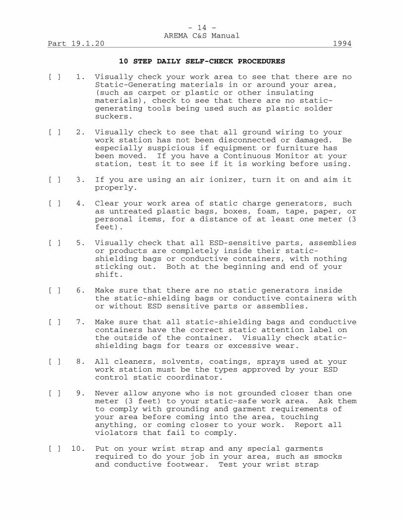
- 14 – AREMA C&S Manual
Part 19.1.20 1994
10 STEP DAILY SELF-CHECK PROCEDURES [ ] 1. Visually check your work area to see that there are no
Static-Generating materials in or around your area, (such as carpet or plastic or other insulating materials), check to see that there are no static-generating tools being used such as plastic solder suckers.
[ ] 2. Visually check to see that all ground wiring to your
work station has not been disconnected or damaged. Be especially suspicious if equipment or furniture has been moved. If you have a Continuous Monitor at your station, test it to see if it is working before using.
[ ] 3. If you are using an air ionizer, turn it on and aim it
properly. [ ] 4. Clear your work area of static charge generators, such
as untreated plastic bags, boxes, foam, tape, paper, or personal items, for a distance of at least one meter (3 feet).
[ ] 5. Visually check that all ESD-sensitive parts, assemblies
or products are completely inside their static-shielding bags or conductive containers, with nothing sticking out. Both at the beginning and end of your shift.
[ ] 6. Make sure that there are no static generators inside
the static-shielding bags or conductive containers with or without ESD sensitive parts or assemblies.
[ ] 7. Make sure that all static-shielding bags and conductive
containers have the correct static attention label on the outside of the container. Visually check static-shielding bags for tears or excessive wear.
[ ] 8. All cleaners, solvents, coatings, sprays used at your
work station must be the types approved by your ESD control static coordinator.
[ ] 9. Never allow anyone who is not grounded closer than one
meter (3 feet) to your static-safe work area. Ask them to comply with grounding and garment requirements of your area before coming into the area, touching anything, or coming closer to your work. Report all violators that fail to comply.
[ ] 10. Put on your wrist strap and any special garments
required to do your job in your area, such as smocks and conductive footwear. Test your wrist strap
- 15 – AREMA C&S Manual
1994 Part 19.1.20
according to manufacturer's instructions and sign the check-off sheet as demonstrated by your ESD coordinator. Check your smocks to see that there are no holes, rips or tears, and that they are clean. Wrist straps are required to be checked once a day at the beginning of your shift, but should be checked after each break and before beginning work after lunch or supper.
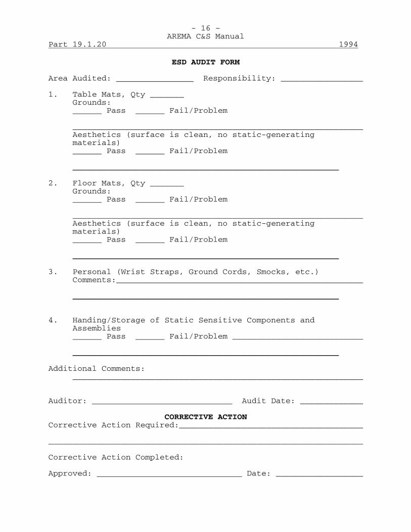
- 16 –AREMA C&S Manual
Part 19.1.20 1994
ESD AUDIT FORM
Area Audited: Responsibility: _________________
1. Table Mats, Qty _______Grounds:
Pass Fail/Problem
____________________________________________________________Aesthetics (surface is clean, no static-generatingmaterials)
Pass Fail/Problem
_______________________________________________________
2. Floor Mats, Qty _______Grounds:
Pass Fail/Problem
____________________________________________________________Aesthetics (surface is clean, no static-generatingmaterials)
Pass Fail/Problem
_______________________________________________________
3. Personal (Wrist Straps, Ground Cords, Smocks, etc.)Comments:___________________________________________________
_______________________________________________________
4. Handing/Storage of Static Sensitive Components andAssemblies
Pass Fail/Problem ___________________________
_______________________________________________________
Additional Comments:____________________________________________________________
Auditor: Audit Date: _____________
CORRECTIVE ACTIONCorrective Action Required:______________________________________
_________________________________________________________________
Corrective Action Completed:
Approved: Date: __________________

AMERICAN RAILWAY ENGINEERING AND MAINTENANCE OF WAY ASSOCIATION
COMMUNICATIONS & SIGNALS MANUAL
Section 20 – Inductive Interference
2002

This page intentionally left blank
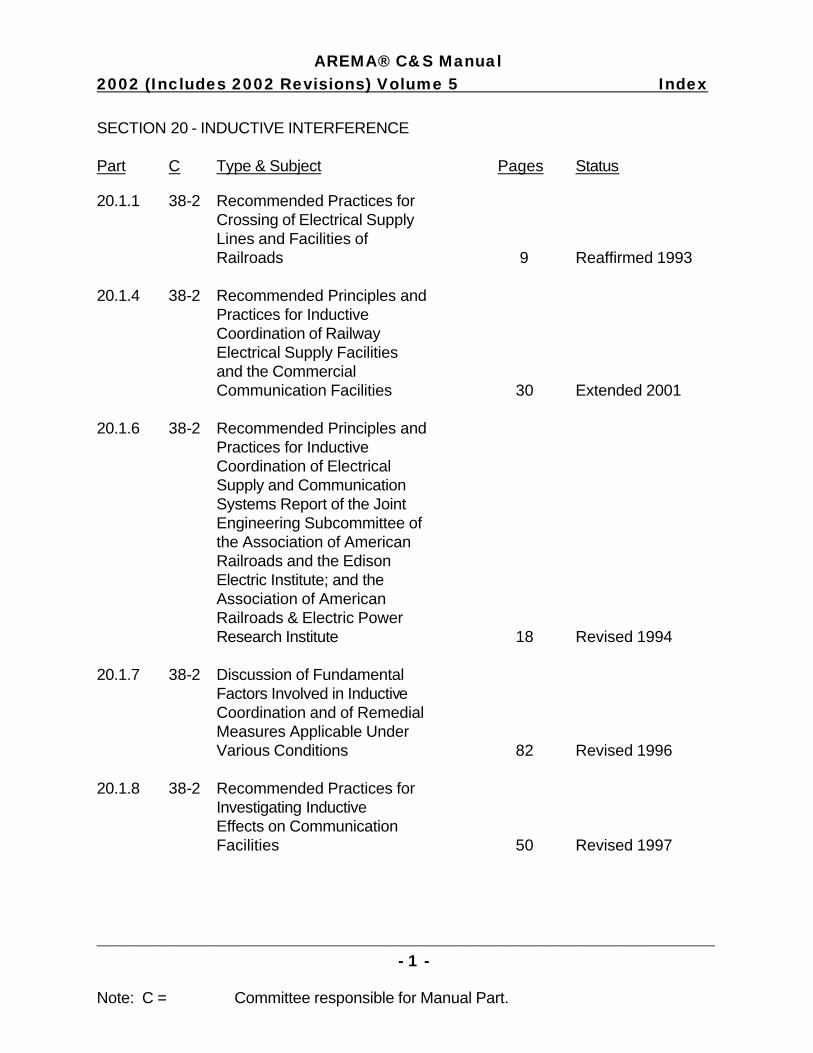
AREMA® C&S Manual 2002 (Includes 2002 Revisions) Volume 5 Index SECTION 20 - INDUCTIVE INTERFERENCE Part C Type & Subject Pages Status
______________________________________________________________- 1 -
Note: C = Committee responsible for Manual Part.
20.1.1 38-2 Recommended Practices for Crossing of Electrical Supply Lines and Facilities of Railroads 9 Reaffirmed 1993 20.1.4 38-2 Recommended Principles and Practices for Inductive Coordination of Railway Electrical Supply Facilities and the Commercial Communication Facilities 30 Extended 2001 20.1.6 38-2 Recommended Principles and Practices for Inductive Coordination of Electrical Supply and Communication Systems Report of the Joint Engineering Subcommittee of the Association of American Railroads and the Edison Electric Institute; and the Association of American Railroads & Electric Power Research Institute 18 Revised 1994 20.1.7 38-2 Discussion of Fundamental Factors Involved in Inductive Coordination and of Remedial Measures Applicable Under Various Conditions 82 Revised 1996 20.1.8 38-2 Recommended Practices for Investigating Inductive Effects on Communication Facilities 50 Revised 1997

This page intentionally left blank

- 1 – AREMA C&S Manual
1993 Part 20.1.1
Recommended Practices for Crossings of Electrical Supply Lines and Facilities of Railroads Reaffirmed 1993 (9 Pages) The following is a report of the Joint Engineering Committee
of the Association of American Railroads and the Edison Electric Institute.
A-Forward A-1 After a number of years of cooperative study of the problem
of mechanical coordination at crossings of electrical supply lines and facilities of railroads, the AAR-EEI Joint Engineering Committee issued in August 1946 a report presenting principles and practices together with a set of specifications. These specifications were based on the Fifth Edition of the National Electrical Safety Code. In the light of the subsequent cooperative handling of crossing problems by the electric utility companies and the railroads it appears that a detailed set of specifications supplementary to the National Electrical Safety Code no longer is necessary and, further, that continuance of AAR-EEI specifications periodically revised to reflect revisions in the National Electrical Safety Code would require wasteful duplication of efforts. Accordingly, the practices have been revised to refer to the latest revision of the National Electrical Safety Code as the guide for construction at crossings.
A-2 The following Principles and Practices for Crossings of
Electrical Supply Lines and Facilities of Railroads are recommended for use in the handling of mutual problems at crossings, in the interest of safety, uniformity, and economy. They have been approved as recommended practice by the Association of American Railroads and the Edison Electric Institute.
A-3 A typical crossing drawing (Figure 2011-1) and instructions
for its preparation are included in this report. B-Introductory B-1 The proper solution of any engineering problem involving
more than one individual or group can best be obtained through cooperation and a mutual determination of the best engineering methods for arriving at the desired result.
B-2 Both railroad and electrical supply utilities render service
demanded by the public. The facilities of each exist in the same territory, and crossings of these facilities are unavoidable if service conditions of both utilities are to be met. These crossings should be made with due regard to safety of the public, the protection of the employees and facilities of both utilities, and to the quality of the

- 2 – AREMA C&S Manual
Part 20.1.1 1993
service of each. The burden of expense that will be necessarily imposed on the service of each, because of the common occupancy of the same territory, should be as light as is consistent with the necessary conditions of safety. The proper establishment of these crossings is, therefore, a mutual duty on the part of these utilities to the public.
B-3 Cooperative consideration to the coordination of the
facilities of each should be given: a. When new facilities of either character are to be
constructed. b. When existing facilities are to be modified, relocated,
or reconstructed. B-4 These crossing problems involve mutual duties on the part of
each utility to the other and a common duty to the public. Close cooperation is required if the best results, measured in service to the public, are to be secured. These problems may be grouped as follows:
a. Inductive Coordination: These involve inductive
relations between electrical circuits of all kinds when they occupy positions of proximity to each other. Inductive coordination problems are considered in the report on "The Inductive Coordination of Electrical Supply and Communication Systems" issued October 7, 1936, by the Joint General Committee of the Association of American Railroads and Edison Electric Institute.
b. Mechanical Coordination: Mechanical coordination
problems relate mainly to clearances and strength of construction and arise in connection with crossings, since a physical contact between the facilities of the utilities may constitute a hazard or impair service. These problems must be treated only in the light of such physical relations.
B-5 It is recommended that the following principles and
practices be used as a guide in connection with mechanical coordination problems.
B-6 Nothing in these principles and practices should be
construed as superseding state, municipal, or other legal requirements.
C-Principles C-1 It should be the duty of each utility to expedite, insofar
as practicable, all work incident to necessary crossings between the facilities of the two utilities.
- 3 – AREMA C&S Manual
1993 Part 20.1.1
C-2 Each utility should be the judge of the quality and requirements of its own service, including the general character and design of its own facilities subject to these principles and practices.
C-3 Each utility should provide and maintain facilities adequate
to meet the service requirements, including such reasonable future modifications in these facilities as changing conditions indicate to be necessary and proper.
C-4 Each utility should cooperate with the other utility so
that, in carrying out the foregoing duties, proper consideration will be given to the mutual problems that may arise and so that the utilities can jointly determine the best engineering solution in situations where the facilities of both are involved.
C-5 Joint consideration by both utilities of safety, service,
convenience, and economy, and the trend of development of both utilities, should determine:
a. The general character of construction of all crossings. b. The best engineering solution for the coordinated
arrangement and design of facilities at crossings. c. The administrative methods for establishing,
maintaining, altering, or removing crossings. C-6 The utilities at interest in a locality should maintain
close cooperation and each notify the others of any intent to build new or extend existing facilities which might tend to contribute to the creation or modification of a crossing.
C-7 When new crossings are contemplated, they should be so
located and planned as to minimize interference with existing facilities.
C-8 When crossings are to be modified, the allocation of costs
between the parties at interest should be reasonable and equitable, taking into account all factors involved.
C-9 Construction and inductive coordination measures employed at
crossings should be in accordance with mutually acceptable practices.
C-10 Contracts, whether general or specific covering the
crossings, should define conditions for the establishment, construction, maintenance, operation, modification, relocation, or elimination of the crossing. Provision should be made for review and revision of all contracts from time to time.

- 4 – AREMA C&S Manual
Part 20.1.1 1993
D-Practices D-1 Agreements: Agreements may be arranged to cover specific
crossings, all crossings in a given territory, groups of crossings in a given territory, or in any other suitable manner satisfactory to the utilities at interest.
D-2 Notification: When a crossing is to be established, the
utility initiating the crossing should notify the other utility as early in advance of the time of construction as practicable. Such notice should show the proposed location and character of the crossing. The parties should then cooperate and decide as to the fitness of the proposed location and see that construction is in accordance with the latest revision of the National Electrical Safety Code - Part 2, "Safety Rules for the Installation and Maintenance of Electric Supply and Communication Lines."
D-3 Procedure When Crossing is to be Modified: When either
utility finds it necessary to change the character of its facilities at a crossing, it shall so notify the other and both shall cooperate to determine the most satisfactory way to make the modification. The utility whose facilities are to be modified shall promptly carry out the necessary work and the utilities shall cooperate to determine the equitable apportionment of the expense involved in such modification.
D-4 The expense to be apportioned should be the net expense from
which shall be excluded any increased cost on account of the substitution for the existing facilities of other facilities of a greater life or of improved type or of increased capacity.
D-5 Joint Planning: An effective way of handling situations in
a given territory is through the full application of the principles of cooperation, including advance notice, advance planning, and the interchange of information.
D-6 Contracts: In either general or specific contracts, any
provisions treating of the character of the facilities involved should be so worded as not to restrict changes in the character of the facilities of either utility, except that it should be recognized that such changes may involve the modification, relocation, or the elimination of the crossing.
D-7 Legal questions, including the sufficiency of right-of-way
grants held by the respective utilities and the protection of title or property of both utilities, in the case of mortgages, sales, mergers, or consolidations entered into by either, should be given due consideration in the preparation of contracts.

- 5 – AREMA C&S Manual
1993 Part 20.1.1
D-8 Liability: In any terms of a crossing contract dealing with liability for personal or property damage, care should be taken that such terms are reasonable and just.
E-Instruction for Filling out Typical Crossing Drawing
Figure 2011-1 covering power line crossings, was primarily designed to cover proposed crossings but can be used for existing crossings. It should show all the information necessary for the complete checking of the crossings from the standpoint of construction as well as clearances.
E-1 Heading: A. Fill in the correct corporate name of the company or
individual owning the crossing. B. Show the correct location of the proposed or existing
crossing in terms of the exact distance in feet from the nearest milepost.
C. Either plus or minus should be marked out. D. The nearest milepost should be shown. E. Whether located at a public road or street, or not;
either "within" or "not within" should be marked out. F. Show the name of the division. G. Show the name of the subdivision. H. Show the name of the county in which located. I. Show the State in which the crossing is or is to be
installed so that the crossing may be definitely located.
E-2 Elevation and Plan Views: a. The elevation and plan views should be considered
relatively, and the correct mile post shown under j so that pole B in the plan view will be in the same relative location as in the elevation view.
b. The dimensions J, K, K', J', N, O, P, N', O', N", and
P' are for the purpose of checking the construction of the crossing.
c. J, K, K’, and J’ should be measured parallel with the
supply line.
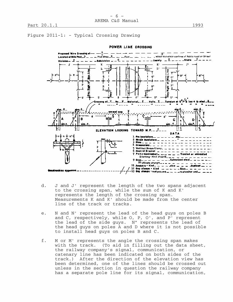
- 6 – AREMA C&S Manual
Part 20.1.1 1993
Figure 2011-1: - Typical Crossing Drawing
d. J and J' represent the length of the two spans adjacent
to the crossing span, while the sum of K and K' represents the length of the crossing span. Measurements K and K' should be made from the center line of the track or tracks.
e. N and N' represent the lead of the head guys on poles B
and C, respectively, while O, P, O', and P' represent the lead of the side guys. N" represents the lead of the head guys on poles A and D where it is not possible to install head guys on poles B and C.
f. M or M' represents the angle the crossing span makes
with the track. (To aid in filling out the data sheet, the railway company's signal, communication, or catenary line has been indicated on both sides of the track.) After the direction of the elevation view has been determined, one of the lines should be crossed out unless in the section in question the railway company has a separate pole line for its signal, communication,
- 7 – AREMA C&S Manual
1993 Part 20.1.1
or catenary wires. This line should be labeled what it is (i.e., signal, communication and/or catenary).
g. Measurements Q and R or Q' and R' represent the
distance from the center line of the supply wires to the two adjacent poles in the railway company's signal, communication, or catenary lines.
h. The remaining measurements represented by L, L', U, T,
S, S', T', and U' in the plan view are for the purpose of checking clearances and should all be measured at right angles to the track.
i. L and L' are the distances from poles B and C,
respectively, to the nearest rail. j. S or S', as the case may be, is the distance from the
center line of the track or tracks to the center line of the railway company's line.
k. T and T' is the distance from the center line of the
railway company's line to its right-of-way line. (On the side opposite to the line the distance from center line of track to the right-of-way line should be indicated under S or S' and T or T' crossed out.)
l. U and U' represent the distance from the right-of-way
line to the crossing poles B and C, respectively. m. Since the distances K and K' are measured parallel with
the supply line and the distances U, T, S, and U', T', S' are measured at right angles to the track, the sum of U, T, and S is a function of the angle, M times the distance K, and the sum of U', T', S', the distance K'.
n. Under V should be filled in the number of supply wires
on the top crossarm: W represents the size of the wires, X the kind of material, such as hard-drawn copper, etc., Y the voltage, and Z the tension in the wires with a temperature of 0F, and with a loading of 1/2 in. of ice and a 4-lb. wind (standard heavy loading).
o. If the supply line is not a straight line from pole A
to pole D, the approximate relative position should be plotted on the plan view to indicate which poles are corner poles and the approximate pull on the pole.
p. In the elevation view the view of the railway company's
line corresponding to the one in the plan view should be crossed out. The horizontal distance from the crossing pole to the nearest wire in the line g or g'
- 8 – AREMA C&S Manual
Part 20.1.1 1993
and the vertical clearance of the supply wires over or under the wires h or h' should be indicated, as well as the clearance of the supply wires above top of rail at 60F. The height above ground, a, plus the depth of setting, b, for each of the four poles, shows the total length of these poles; c represents the height of the guy attachments, where attached to the pole, above ground; d is the circumference of the pole in inches at the top and e the circumference 6 ft. from butt; f represents the normal sag at 60F of the supply wires in the three spans respectively; i represents clearance of lowest conductor above top of rail.
E-3 Crossarms and Pin Spacing: n and n' show the spacing of the
pole pin wires from the center of the pole and o the spacing between wires other than the pole pair; k is the length and l the width of the crossarms used; m represents the spacing between the attachment of the two braces to the crossarm.
E-4 Vertical Profile: p represents the distance between the conductors on pole. q represents the type and make of the vertical strain clamp. r represents the type and make of the strain insulator. s represents the type and make of the neutral bracket or bracket clevis. E-5 Data: 1 represents the type pin insulators used. 2 represents the type strain insulators used. 3 represents the type pins used. 4 represents the type crossarms: their size and material. 5 represents the type strain hardware. 6 represents the type neutral bracket or bracket clevis. 7 and 8 represent the poles: their timber, class and depth set. 9 and 10 represent the guys: their kind, size, and strength. 11 represents the anchors: their kind, size, and depth set.

- 9 – AREMA C&S Manual
1993 Part 20.1.1
12 and 13 represent the guy clamps: their kind, size, and the number used.

This page intentionally left blank
- 1 –AREMA C&S Manual
2001 Part 20.1.4
Recommended Principles and Practices for InductiveCoordination of Railway Electrical Supply Facilities and
the Commercial Communication FacilitiesExtended 2001 (30 Pages)
A. Explanation of TermsFor the purpose of these Principles and Practices, thefollowing terms are used with the meanings as given below:
1. Abnormal Operating Conditions: Electrical operatingconditions resulting when operating arrangements otherthan normal are established on railway electricalsupply circuits.
2. Ampere-Miles: The product of the current in anysection of a circuit in which the current is the samethroughout the section, multiplied by the length of thesection.
a. The ampere-miles of a section of circuit in whichthe current is not the same throughout, is thesummation of the ampere-miles for successivelengths within each of which the current is thesame throughout, and which together make up thesection.
b. For rail-return circuits, the ampere-miles in aspecified section are based upon currents in thecontact conductor system, except in the case ofthree-wire single-phase electrifications, wherethe vector sum of currents in the contactconductor system and the distribution feeders isused as a basis.
3. Communication Circuits: Circuits used for theelectrical transmission of intelligence by wire orcable.
4. Communication Facilities: Communication circuits andtheir associated apparatus.
5. Configuration: The geometrical arrangement intransverse section of any assemblage of generallyparallel conductors including their sizes and theirrelative positions with respect to other conductors andto the earth.
6. Contact Conductor: A conductor, other than trafficrails, with which devices on railway cars orlocomotives make contact to collect electric currentfor the operation of motors and other apparatus ontrains. A contact conductor may be either a wire or a
- 2 –AREMA C&S Manual
Part 20.1.4 2001
rail.
7. Contact Conductor System: The system of contactconductors together with any supporting wiresmetallically connected thereto and including contactconductor feeders.
8. Contact Conductor Feeder: A conductor that connectsthe contact conductors to the substation buses. Insome instances contact conductor feeders may be carriedalong the railway and connected to the contactconductors at one or more points.
9. Coordinated Transpositions: Transpositions which areinstalled, either in railway electrical supply circuitsor in communication circuits or in both, for thepurpose of recuding coupling; and which are locatedeffectively with respect to the discontinuities of theexposure and are so arranged that those in each circuitare located with due regard to those in the othercircuit.
10. Coupling: The inter-relation of neighboring circuitsby electric or magnetic induction or both, or byconduction through a common earth path, or bycombinations thereof.
11. Discontinuity: A point at which there is an abruptchange in the physical relations of railway electricalsupply circuits and communication circuits or in theelectrical characteristics of either circuit.Transpositions, however, are not considered asdiscontinuities.
12. Distribution Feeder: A conductor used in thethree-wire system of railway electrification that, incombination with the contact conductor system, formsthe primary circuit for the substationauto-transformers.
13. Fault Conditions: Conditions resulting when a fault toground or a short circuit occurs on a railwayelectrical supply circuit.
14. General Coordinated Methods: Those methods reasonablyavailable for general application to communicationfacilities or railway electrical supply facilities thatcontribute to inductive coordination without specificconsideration of the requirements of individualinductive exposures.
15. Inductive Coordination: The location, design,
- 3 –AREMA C&S Manual
2001 Part 20.1.4
construction, operation and maintenance ofcommunication facilities and railway electrical supplyfacilities in conformity with harmoniously adjustedmethods which will prevent inductive interference.
Note: Inductive interference is an effect arisingfrom the characteristics and inductiverelations of communication facilities andrailway electrical supply facilities of suchcharacter and magnitude as would prevent thesatisfactory and economical operation of thecommunication facilities if methods ofinductive coordination were not applied.
16. Inductive Exposure: A situation of proximity betweenrailway electrical supply facilities and communicationfacilities under such conditions that inductivecoordination should be considered.
17. Inductive Influence: Those characteristics of railwayelectrical supply facilities that determine thecharacter and intensity of the inductive field thatthey produce.
18. Inductive Susceptiveness: Those characteristics ofcommunication facilities which determine, so far assuch characteristics can determine, the extent to whichsuch facilities are capable of being adversely affectedin giving service, by a given inductive field.
19. Overhead Ground Wires: Wires installed on aerial linesand grounded at intervals, which are intended primarilyto provide lightning protection for the electricalsupply circuits, or to limit potential rise ofstructures in case of fault, or both. Such wires alsoprovide a certain amount of shielding to communicationcircuits involved in inductive exposures.
20. Phase Conductor: An insulated conductor belonging to atransmission or distribution circuit and connected toan energized terminal at a point of power supply. Iftwo or more such conductors of a circuit are connectedto a single terminal at the power source and at theload, the group of such conductors so operated inparallel is considered as one phase conductor. In atwo-phase, three-wire system in which two phases have acommon terminal, the conductor connected to thisterminal is regarded as a phase conductor.
21. Potential-Neutralizing Conductor: A conductor uponwhich is impressed a voltage substantially equal andopposite to the potential of a disturbing conductor and
- 4 –AREMA C&S Manual
Part 20.1.4 2001
which is suitably installed near the disturbingconductor so as to neutralize electric induction.
22. Railway Electrical Supply Circuits: Railway circuits(including electric transmission, distribution,propulsion, and associated circuits), used to supplyelectric power either for the operation of a railway,or for devices or machinery used by a railway, such assignals, lights, motors, etc. (Does not includecommunication circuits.)
23. Railway Electrical Supply Facilities: Railwayelectrical supply circuits, equipment or other railwayplant associated with such circuits. (Does not includecommunication facilities.)
24. Rail-Return Circuits: Railway electrical supplycircuits which are so arranged that the traffic railsform part of the circuit for current carrying purposes.Such circuits may carry alternating current or directcurrent or both and include such feeders and auxiliaryconductors as may be connected thereto, either throughdirect metallic connection or throughauto-transformers.
25. Residual Current: The vector sum of the currents inthe phase conductors of a transmission or distributioncircuit.
26. Residual Voltage: The vector sum of the voltages toground of the phase conductors of a transmission ordistribution circuit.
27. Return Feeder: A conductor used to supplement thecurrent carrying capacity of the traffic rails.
28. Shielding: An effect, due to the presence of groundedconductors or grounded conducting structures, which ingeneral is a reduction in coupling between neighboringcircuits.
29. Shield Wires: Wires that are installed primarily toprovide reduction in coupling by shielding.
30. Specific Coordinated Methods: Those additional methodsapplicable to specific situations, where generalcoordinated methods are inadequate.
31. Substation: Transformation, conversion, or switchingequipment, together with buses, circuit breakers,control equipment, etc., from which energy is supplieddirectly to the contact conductor system.
- 5 –AREMA C&S Manual
2001 Part 20.1.4
32. Stub-End Feed: A substation section, or a partthereof, in which energy is supplied in only onedirection to loads in that substation section.
33. Substation Section: Where the contact conductor systemis not sectionalized or is sectionalized only atsubstations, a section between successive substationsis a substation section. Where energy for a givenlength of the contact conductor system is suppliedentirely from a single substation, either at thesubstation or by means of contact conductor feedersthat extend from the substation, the section suppliedfrom the single substation is a substation section.
34. Transmission and Distribution Circuits: Railwayelectrical supply circuits in which current normally issubstantially confined to metallic conductors,insulated from ground, having substantially balancedvoltages to ground and carried on the same orimmediately adjacent supporting structures or in thesame or immediately adjacent duct runs. Suchtransmission and distribution circuits generally carryalternating current and may be single-phase ormulti-phase. When grounded, such circuits are groundedonly at neutral or substantially balanced points asregards voltage to ground.
Transmission and distribution circuits are generallydistinguished from each other by the manner in whichthey are used. Transmission circuits are generallyused to transmit power in bulk to suitable locationsfrom which it can be distributed to points of actualutilization over the distribution circuits. Whilerail-return circuits may fall under this classificationof distribution circuits, the treatment of inductivecoordination problems involving rail-return circuitsdiffers in many respects from that usually given toother types of circuits, and therefore rail-returncircuits have been considered separately in thesepractices.
35. Transposition: An interchange of position ofconductors of a circuit between successive lengths.
B. Principles1. Scope: Railway electrical supply facilities and
commercial communication facilities supply essentialpublic services and these facilities frequently requireinductive coordination. The Principles herein areintended to form a basis for the cooperative handlingof matters in connection with the inductivecoordination of these facilities.
- 6 –AREMA C&S Manual
Part 20.1.4 2001
Where coordination between railway communicationfacilities and commercial communication facilities isnecessary, such of these Principles as apply should befollowed.
2. Duty of Coordination: Railway electrical supplyfacilities and commercial communication facilitiesshould be located, designed, constructed, operated andmaintained in conformity with general coordinatedmethods. These methods should include limiting, as faras practicable, the inductive influence of the railwayelectrical supply facilities, the inductivesusceptiveness of commercial communication facilities,and the coupling between these facilities.
Where general coordinated methods will be insufficient,such specific coordinated methods suited to thesituation should be applied to the facilities of eitheror both kinds as will most conveniently andeconomically prevent interference, the methods to bebased on the then existing knowledge of the art.
3. Cooperation: In order that full benefit may be derivedfrom these Principles and in order to facilitate theirproper application, railway and communication companiesbetween whose facilities inductive coordination may nowor later be necessary, should adequately cooperatealong the following lines:
a. Railway and communication companies operating inthe same general territory should each give to theother advance notice of any construction,reconstruction, or change in operating conditionsof its facilities that are concerned or likely tobe concerned in situations requiring inductivecoordination.
b. If it appears to either company that problems ofinductive coordination requiring jointconsideration are involved, the companies shouldconfer and cooperate to secure inductivecoordination in accordance with the Principles setforth herein.
c. To assist in promoting conformity with thesePrinciples, an arrangement should be set upbetween the railway and the communicationcompanies whose facilities occupy the same generalterritory, for the interchange of pertinent dataand information, including that relative toproposed and existing construction and changes inoperating conditions of facilities concerned or
- 7 –AREMA C&S Manual
2001 Part 20.1.4
likely to be concerned in situations which requireinductive coordination.
4. Choice of Specific Coordinated Methods: When specificcoordinated methods are necessary and there is a choiceof such methods, those that provide the bestengineering solution should be adopted.
a. The specific methods selected should be such as tomeet the service requirements of both systems inthe most convenient and economical manner withoutregard to whether they apply to the railwayelectrical supply facilities or to thecommunication facilities, or to both.
b. In determining which specific methods are mostconvenient and economical in any situation, allfactors for all facilities concerned should betaken into consideration, including presentfactors and those which can be reasonablyforeseen.
c. Neither party should assume to be the judge of theservice requirements of the other system, or ofwhat constitutes good practice in that system.
5. Inductive Coordination for Existing Situations:Railway and communication companies should exercise duediligence in applying coordinated methods to existingsituations in accordance with these Principles.
When railway electrical supply facilities orcommunication facilities are generally reconstructed,rearranged, or extended, the new or changed partsshould be brought into conformity with thesePrinciples.
6. Coordinated Locations for Lines: Railway electricalsupply circuits are, as a rule, located along railwayrights-of-way as it is usually impracticable to locatethese circuits elsewhere. In order to provide adequateservice communication lines are located along streets,highways and on private rights-of-way, and these routesare often adjacent to railway rights-of-way. Moreover,it is impracticable to change certain maincommunication routes when these are established eitherby extensive existing construction or by servicerequirements. However, where alternative routes foreither class of circuit are available, these should beconsidered, together with other possible methods ofcoordination.
- 8 –AREMA C&S Manual
Part 20.1.4 2001
7. Deferred General Coordination: While railwayelectrical supply facilities or communicationfacilities not concerned or likely to be concerned inthe near future in situations requiring inductivecoordination should usually conform to generalcoordinated methods, either of these facilities,pending the incoming or development of the other, may,if deemed economically advantageous, occupy locationsor use types of construction and operating methodsother than those conforming to general coordinatedmethods. However, non-coordinated facilities should bealtered when and as necessary to conform to suchmethods upon the incoming or development of the otherfacilities conforming to general coordinated methods.Where, however, all things considered, specificcoordinated methods will be sufficient and moreeconomical than general coordinated methods in anyparticular case, specific coordinated methods may beapplied.
8. Special Methods of Coordination: Where the inductivecoordination of railway electrical supply facilitiesand communication facilities cannot be technically oreconomically established under the methods ofcoordination covered by these Principles, cooperativeconsideration should be given to determine what specialmethods should be employed.
C. Practices - Introductory1. These recommended Practices supplement and are in
accord with the Principles. They are based onexperience and cooperative investigation and areintended to indicate methods that should be consideredin the inductive coordination of railway electricalsupply facilities and communication facilities.Quantitative discussions are not included since theapplication of the Practices in specific cases willdepend upon the particular circumstances in each caseand the existing state of the art.
2. It is recognized that in the growth and development ofthe railways and communications and as the artprogresses, other mutually satisfactory methods ofcoordination will doubtless be devised. The fact thatsuch other methods are not included herein does notpreclude their use, nor their later incorporation inthese Practices as they may be agreed upon.
3. Electrified railways generally use the traffic rails tocarry power current and, since these rails are noteffectively insulated from ground, a portion of thiscurrent flows in the ground. The treatment of the

- 9 –AREMA C&S Manual
2001 Part 20.1.4
problem of inductive coordination involving suchelectrified railways differs in many respects from thatusually given to supply circuits in which normally thepower current is substantially confined to conductorsthat are insulated from ground. It has been foundadvisable, therefore, to divide the subject matter onrailway electrical supply facilities into two sections,namely, "Practices Applicable to Transmission andDistribution Circuits and Associated Equipment"(Section F) and "Practices Applicable to Rail-ReturnCircuits and Associated Equipment" (Section G).
4. In order that the intent of the Principles may becarried out, the Practices herein designated as"General Coordinated Methods" should be applied to allrailway electrical supply facilities and commercialcommunication facilities except as deviations may bemade under the principle of "Deferred GeneralCoordination" (Paragraph B-7 of Principles). In casesof inductive exposure where these general coordinatedmethods are insufficient, such of the Practices hereindesignated, as "Specific Coordinated Methods"(Paragraphs E-2, F-2 and G-2) should also be applied,as they will provide the best engineering solution. Indetermining what specific coordinated methods should beapplied in such cases, consideration of the railwaycommunication facilities should be included.
D. Mutually Applicable Practices1. Notice and Cooperation: Arrangements should be set up
between railway and communication companies operatingin the same general territory providing for notice, asfar in advance as practicable, of any construction,changes in construction or changes in operatingconditions of their facilities, which are concerned orare likely to be concerned in situations requiringinductive coordination. These arrangements shouldinclude a list of items regarding which each companywill give advance notice to the other company andshould specify the territory included in each sucharrangement. For each such territory each companyshould designate an official to receive and sendadvance notices and should adopt such routines withintheir respective organizations as will provide for theproper forwarding of advance notices and the prompthandling of notices that are received. An illustrativearrangement between a railway company and a commercialcommunication company is shown in Appendix A.
Where situations arise which in the opinion of eithercompany require inductive coordination, the railway andcommunication companies should cooperate in determining
- 10 –AREMA C&S Manual
Part 20.1.4 2001
and carrying out those methods which provide the bestengineering solution in each case and to this end thereshould be complete interchange of pertinentinformation.
2. Operating Instructions: Railway companies should adoptoperating instructions that outline the procedure to befollowed when abnormal operating or fault conditionsexist. Communication companies should adopt operatinginstructions specifically outlining the procedure fornotification of Railways when inductive disturbancesarise on their communication circuits that appear to bedue to the influence of Railway electrical supplyfacilities.
If abnormal operating conditions on railway electricalsupply facilities should temporarily prevent the use ofcertain communication facilities, and these effects canbe avoided only by rerouting the traffic or rearrangingthe facilities of one or both companies, jointconsideration should be given to such arrangements aswill give the best overall results.
3. Records: Railway companies should keep operatingrecords of their electrical supply facilities andcommunication companies should keep a record ofdisturbances on their communication facilities so thata study of such disturbances as appear to be due toconditions on the railway will be facilitated.
4. Limitation of Influence and Susceptiveness: Indesigning, specifying or otherwise determining thecharacter, location, construction, and arrangement ofrailway electrical supply facilities or commercialcommunication facilities, or the character, quality,arrangement, and suitability of materials or apparatusmaking up these facilities, and in operating andmaintaining these facilities, all factors which wouldcontribute to inductive influence or inductivesusceptiveness should be limited as far as necessaryand practicable.
The mechanical and electrical design and constructionof railway electrical supply facilities and commercialcommunication facilities should conform to good modernpractice.
5. Coupling: Efforts should be made to arrange railwayelectrical supply facilities and commercialcommunication facilities so as to minimize the couplingbetween them.
- 11 –AREMA C&S Manual
2001 Part 20.1.4
a. While coupling may be reduced by increasing theseparation in sections of the exposure, othermethods of coordination should be considered alongwith this method and those arrangements adoptedwhich, in combination, will give the bestengineering solution. In the consideration ofseparation as a means of reducing coupling, futureservice requirements and premanency of locationshould be included.
b. Where communication facilities and railwayelectrical supply facilities are located inproximity to each other, cooperative considerationshould be given to the relative locations ofgrounds with a view to limiting coupling.
6. Changes in Systems or Methods of Operation: Inchanging systems or methods of operation, precautionshould be taken to avoid increasing, and an effort madeto decrease the inductive influence or inductivesusceptiveness. If any condition develops whichincreases these factors, an effort should be madepromptly to remedy such condition.
7. Maintenance: Railway electrical supply facilities andcommunication facilities should be maintained in goodcondition. Repairs and renewals should be madepromptly.
E. Practices Applicable to Communication Facilities1. General Coordinated Methods: The following practices
should be applied to all commercial communicationfacilities except as deviations may be made under theprinciple of "Deferred General Coordination" (ParagraphB-7 of Principles).
a. Protection: Protective devices should be sodesigned, constructed, installed and maintained asnot to cause unavoidable unbalances orinterruptions of communication circuits.
b. Inspection: Routine inspections and tests shouldbe made with a view to maintaining electricalbalance and efficiency of communicationfacilities.
c. Discontinuities: Discontinuities should belimited to the number required by the conditionsto be met.
d. Lines: In order to minimize line unbalances, theresistance, inductance, capacitance and leakage
- 12 –AREMA C&S Manual
Part 20.1.4 2001
conductance of one side of a circuit in eachsection thereof, should be as nearly equalrespectively to the corresponding quantities inthe other side of the same section of the circuitas is necessary and practicable. Some of themethods that should be followed for the purpose oflimiting the unbalance in lines are as follows:
1) Transpositions: The capacitances to earth ofthe two sides of a metallic circuit on anopen-wire line should be suitably balanced bytranspositions. Before a metallic circuit isplaced in service, a check should be made toinsure that the transpositions are correctlylocated and properly installed.
2) Derived Circuits: In the creation ofcircuits from one or more circuits withoutadding line conductors, due regard should begiven to avoiding unnecessary increases ininductive susceptivness.
a) Phantom circuits should be created onlyfrom similar adjacent pairs. Branchesconnected to one side only of a phantomcircuit should be avoided unlessconnected through repeating coils.
b) If one side circuit of a phantom groupis loaded for voice frequencies, theother side circuit should be similarlyloaded at the same loading points, suchloading to have closely the sameelectrical characteristics.
c) In general, phantom circuits should beused only for toll or trunk circuits,except in cases of long rural circuits.
3) Connections: Efforts should be made toprevent the introduction of unbalance bycontact resistance.
a) In toll cable conductors, all jointsshould be made in accordance with goodpractice for the conditions concerned.In open-wire toll conductors, all jointsshould be made with sleeves or should bewell soldered or welded.
b) All wires should be properly cleanedbefore the joints are made to insure
- 13 –AREMA C&S Manual
2001 Part 20.1.4
good contact.
c) All test connections, terminal boxes andassociated wiring should be designed,constructed, installed and maintained soas to avoid circuit unbalances as far aspracticable.
4) Use of Cable: Consideration should be givento fiber optics or placing circuits in cableat the time of rebuilding open wire lines.
e. Apparatus: All apparatus connected to acommunication circuit should be so designed,constructed, installed and maintained as tominimize, within practical limits, the unbalancesof the series impedance and admittance to groundof the two sides of the circuit.
2. Specific Coordinated Methods: The specific practiceswhich follow are to be used in addition to the generalpractices to supplement the latter, in so far as may benecessary and practicable, in cases where railwayelectrical supply facilities and commercialcommunication facilities are involved or are about tobe involved in situations requiring inductivecoordination.
a. It is not intended that all of these practicesshould be applied in any specific case, but ineach instance that practice or those practicesshould be selected which, in combination with themethods that are to be applied to the railwayelectrical supply facilities, will afford the bestengineering solution.
b. Special Devices: Consideration should be given tothe use of special devices, such as neutralizingtransformers, sectionalizing transformers,filters, resonant shunts, drainage, specialprotective devices, acoustic shock reducers, etc.,in any case where they may offer benefit, andwhere service requirements permit.
c. Lines1) Configuration: Where service requirements
permit a choice of configuration of acommunication circuit or a group ofcommunication circuits, consideration shouldbe given to the selection of a configurationsuch as to limit inductive susceptiveness.
- 14 –AREMA C&S Manual
Part 20.1.4 2001
2) Shielding: Where an open-wire line isinvolved in an inductive exposure,consideration should be given to the use ofmethods of shielding in order to reduceinductive effects. This should includeconsideration of replacement of the open-wireline by aerial or underground cable or fiberwithin the exposure.
Where communication circuits are carried incable, consideration should be given to theuse of properly arranged and installedgrounds on cable sheaths, or other methods ofshielding.
3) Coordinated Transpositions: Considerationshould be given to the use of arrangements oftranspositions in open-wire lines involved ininductive exposures, to reduce coupling.Such transpositions should be located atsuitable intervals consistent with thediscontinuities of the exposure and thelocations of transpositions in theparalleling Railway electrical supply lines.
d. Apparatus1) Party Line Stations: Consideration should be
given to improving the electrical balance ofparty line stations where noise frequencyeffects are involved.
Where low frequency effects are involved,consideration should be given to biasingringers, the use of relay sets, or otheravailable methods.
2) Central Office Equipment: Where a tollcircuit may be switched to another tollcircuit or to a subscriber's circuit,consideration should be given to the use ofrepeating coils or other apparatus which willadequately limit the inductivesusceptiveness.
Where series apparatus is applied to localcommunication circuits, consideration shouldbe given to arranging it so that equalimpedances are inserted in each side of thecircuit where necessary and practicable.
3) Ground Connections: Ground connections, ifemployed on equipment connected to
- 15 –AREMA C&S Manual
2001 Part 20.1.4
communication circuits, should, whenpracticable, be at neutral or balancedpoints.
e. Records: A detailed record should be kept ofdisturbances in communication circuits involved ininductive exposures where a study is advisable.Such records should as fully as practicableinclude date, time, duration, circuit designation,location, nature, effects and probable cause ofthe disturbances, and the method and time ofclearing the circuits.
All of the above records, or a convenient summarythereof, should be available for the purpose ofanalyzing causes and effects of disturbances.
F. Practices Applicable to Transmission and DistributionCircuits and Associated Equipment1. General Coordinated Methods: The following practices
should be applied to all transmission and distributioncircuits and associated equipment except as deviationmay be made under the principle of "Deferred GeneralCoordination" (Paragraph B-7 of Principles).
a. Residual Voltages and Currents: Residual currentsreturning by remote paths, and residual voltages,should be limited as far as practicable.
b. Unsymmetrical loads between phases, which wouldgive rise to residual currents returning by remotepaths, or to residual voltages, should be avoidedas far as practicable.
c. Discontinuities: Discontinuities should belimited to the number required by the conditions.
d. Switching: In all switching operations careshould be taken to limit the production oftransient disturbances.
Care should be taken to avoid repeatedlyenergizing, at normal voltage, a transmission ordistribution circuit in order to locate or clear afault.
e. Connections: Care should be taken to avoidcontact resistance that might increase inductiveinfluence.
f. Lines: In order to limit the residual currentsand voltages arising from line unbalances, the
- 16 –AREMA C&S Manual
Part 20.1.4 2001
resistance, inductance, capacitance and leakageconductance of each side in any section of acircuit should be as nearly equal as practicableto the respective corresponding quantities in anyother side of the same section of the circuit.Some of the methods and means for limitingunbalance in lines are described below:
1) Configuration: Where there is a choicebetween two or more configurations ofopen-wire lines, consideration should begiven to the use of such configuration of acircuit or a group of circuits as willprovide the superior balance.
2) Transpositions: The capacitances to earth ofthe phase conductors of a circuit should besuitably balanced by transpositions, as faras necessary and practicable.
3) Branch Circuits: Where branches employingless than the total number of phases are tobe used, they should be so planned as not togive rise to excessive residual currentreturning by remote paths or to excessiveresidual voltages. This can be accomplishedby limiting the length of such branchcircuits and distributing them among thephases of the main circuit.
4) Three-Phase Four-Wire Circuits withMulti-Grounded Neutral: On three-phasefour-wire circuits with multi-groundedneutral, single-phase and open-wye loadsshould be limited in size and so distributedamong the phases as to limit the unbalancedload current.
Where energy is supplied to three-phasefour-wire circuits with multi-groundedneutral from a delta-wye-connectedtransformer bank, consideration should begiven to connecting the neutral ofthree-phase wye-delta-connected loadtransformer banks to the neutral wire.
5) Overhead Ground Wires: Where overhead groundwires are to be installed on transmission ordistribution lines, consideration should begiven to such kind and size of wire as will,through shielding, reduce coupling as far aspracticable.
- 17 –AREMA C&S Manual
2001 Part 20.1.4
g. Apparatus:1) Rotating Machinery: Synchronous machines
should be specified and selected so as tohave a waveform in which the harmoniccomponents are limited as far as practicable.
a) Where three-phase generators havinggrounded neutrals are to be connectedeither directly or throughwye-wye-connected transformer banks tothree-phase transmission or distributioncircuits, means should be used tosuppress triple harmonics as far asnecessary and practicable. This may beaccomplished in the design of thegenerators, or by the use of auxiliaryequipment, or, where wye-wye transformerbanks are used, by delta-connectedtertiary windings on the transformers.
b) Induction motors and generators shouldbe specified and selected, the harmonicvoltages and currents of which, as faras practicable, will not increase theinductive influence of the system towhich they are connected.
2) Transformers: In order that the waveform ofvoltage and current may be affected as littleas practicable by transformers, suchapparatus should be so designed as not torequire operation at excessive magneticdensities. In the installation, connection,and operation of transformers, care should betaken to avoid normal voltages in excess ofrating, and excessive magnetizing currents.
a) Where a three-phase transmission ordistribution circuit is connecteddirectly to the wye-connected windingsof transformers with grounded neutral,or to wye-connected auto-transformerswith grounded neutral, low impedanceclosely coupled delta-connectedwindings, or other suitable means foradequately limiting the triple harmoniccomponents of residual currents andvoltages, should be employed.
b) Care should be taken that the individualunits in each bank of transformers,operated with a grounded neutral and
- 18 –AREMA C&S Manual
Part 20.1.4 2001
connected to a three-phase transmissionor distribution circuit, aresubstantially alike as to electricalcharacteristics and that they aresimilarly connected.
3) Circuit Breakers: Each circuit breakercontrolling the supply of energy totransmission or distribution circuits shouldhave all of its poles arranged for gangoperation. These circuit breakers should beautomatic for short circuits between phasesand from phase to ground, and should be of atype that will disconnect the faulty circuitin as short a time as practicable.
4) Protective Apparatus: Protective apparatusshould be such that it will not unnecessarilyadd to transient disturbances and should, asfar as practicable, avoid or limit suchtransient disturbances.
a) Lightning arresters should be soadjusted as not to operate at smallover-voltages.
b) Lightning arresters that have beentemporarily withdrawn from serviceshould not be replaced in service untilthey are in proper operating condition.
c) Where lightning arresters requiringperiodic charging are used on atransmission or distribution circuitinvolved in an inductive exposure, theyshould be equipped with auxiliaryresistances and contacts.
d) Routine inspections and tests should bemade to insure that adjustments in allprotective apparatus are properlymaintained.
5) Ground Connections: Ground connections, ifemployed on apparatus connected totransmission or distribution circuits, shouldbe made at balanced or neutral points. Thisprecludes the use of grounded single-phaseloads and grounded open-wye transformerconnections on three-phase systems.
Consideration should be given to the use of
- 19 –AREMA C&S Manual
2001 Part 20.1.4
current limiting impedance inneutral-to-ground connections of apparatuselectrically connected to transmission ordistribution circuits.
2. Specific Coordinated Methods: The specific practiceswhich follow are to be used in addition to the generalpractices to supplement the latter, in so far as may benecessary and practicable, in cases where transmissionand distribution circuits and communication facilitiesare involved or are about to be involved in situationsrequiring inductive coordination.
a. It is not intended that all of these practicesshould be applied in any specific case, but ineach instance that practice or those practicesshould be selected which, in combination with themethods that are to be applied to thecommunication facilities, will afford the bestengineering solution.
b. Lines:1) Configuration: Where physical and economic
conditions permit a choice of configurationof transmission or distribution circuitswithin inductive exposures, the configurationselected should be such as to limit theinductive influence most effectively.
2) Branch Circuits: Consideration should begiven to the isolation of branch circuitsconsisting of less than the total number ofphases of the main circuit, by means oftransformers, when such main or branchcircuits are involved in inductive exposures.
3) Coordinated Transpositions: Considerationshould be given to the use of transpositionsin transmission and distribution circuits,within inductive exposures, for the purposeof reducing coupling. Such transpositionsshould be located at suitable intervals,consistent with the discontinuities of theexposure and the locations of transpositionsin the communication lines.
4) Shielding: Consideration should be given tothe installation of shield wires in inductiveexposures. In order to obtain the fullbenefit of such shield wires they should beeffectively grounded at the ends of theexposures and at intervals within the
- 20 –AREMA C&S Manual
Part 20.1.4 2001
exposures.
Where overhead ground wires are to beemployed on transmission or distributionlines, consideration should be given to theuse of such kind and size of wire as will,through shielding, reduce coupling as far aspracticable; also to the effective groundingof these wires within and adjacent to theexposure and to the connection of these wiresto the station grounds at power supply pointswhere the neutrals of the transmission ordistribution circuits concerned are grounded.
c. Apparatus1) Wave Shape: Where service conditions permit,
consideration should be given to specialmeans and devices for reducing the amplitudeof harmonics on systems involved in inductiveexposures.
a) Where a ground connection on thearmature winding of an alternatingcurrent generator or motor, directlyconnected to a transmission ordistribution circuit, results in tripleharmonics on circuits involved ininductive exposure, means should beemployed to reduce the triple harmonicsas far as necessary and practicable.
b) Where rectifiers, arc furnaces or otherapparatus, distort the voltage orcurrent waveform of a transmission ordistribution circuit involved in aninductive exposure, consideration shouldbe given to the use of suitableauxiliary apparatus or other means tolimit such distortion.
2) Lightning Arresters: Where disturbancesarise at times of charging lightningarresters, notwithstanding compliance withSection F-1-7-d, every effort should be madeto do the charging at times of minimumtraffic load on the communication facilitiesconcerned.
3) Circuit Breakers: Consideration should begiven to the installation of automaticcircuit breakers or their equivalent tocontrol the supply of energy to transmission
- 21 –AREMA C&S Manual
2001 Part 20.1.4
or distribution circuits involved ininductive exposures.
4) Current Limiting Devices: Considerationshould be given to the use of currentlimiting devices in either the line wires orthe neutral-to-ground connection oftransmission and distribution circuits, asfar as necessary and practicable.
d. Records: Railway companies should keep detailedoperating records of their transmission anddistribution circuits which are involved ininductive exposures where a study of disturbancesin the communication facilities concerned isadvisable. Such records should, as fully aspracticable, include date, time, duration, circuitdesignation, location, nature and cause oftrouble, method and time of clearing the troubleand any special or abnormal operating conditions.
All of the above records, or a convenient summarythereof, should be available for the purpose ofanalyzing cause and effect of disturbances oncommunication circuits.
G. Practices Applicable to Rail-Return Circuits and AssociatedEquipment1. General Coordinated Methods: The following practices
should be applied to all rail-return circuits andassociated equipment except as deviation may be madeunder the principle of "Deferred General Coordination"(Paragraph B-7 of Principles).
a. General Considerations: In the design,construction and maintenance of rail-returncircuits and associated equipment, considerationshould be given to facilities and methods ofoperation which will limit, as far as practicable,the inductive effects on neighboring communicationfacilities.
b. Electrified Railways: Single-Phase and DirectCurrent.
1) Design of Network including Distribution ofCurrent: In the design and arrangement ofelectrified railway circuits, considerationshould be given to means of limiting thetotal ampere-miles in rail-return circuits oneither side of any load or short circuit, andto equalizing the total ampere-miles on the
- 22 –AREMA C&S Manual
Part 20.1.4 2001
two sides.
Means for obtaining benefit in these respectsexist, in the case of alternating currentelectrifications, in the proper proportioningof impedances among the transmission circuits(including the distribution feeder - contactconductor circuits of three-wire systems),the system of rail-return circuits and thesubstation transformers, and in the spacingof substations. Similar methods exist in thecase of direct current electrifications.
2) Limitation of Short Circuit Current: In thedesign and arrangement of alternating currentelectrified railway circuits, including theassociated transmission and distributionsystem and the facilities which supply energythereto, consideration should be given tomeans of limiting short circuit currents inrail-return circuits. On branch lines havinga power demand that is light compared to thatof the main system, it is often practicableto design the network so as to limit shortcircuit currents to a greater extent that canbe done on the main system.
On direct current electrifications,consideration should be given to the use ofmeans of controlling the rate of change ofshort circuit currents on contact conductorsystems.
3) Contact Conductor Systems: Contactconductors should be so arranged that theycan be sectionalized either normally or attimes of abnormal conditions.
a) Contact conductor systems not normallysectionalized, should be so arrangedthat they will be sectionalizedautomatically at times of fault or shortcircuit.
b) Consideration should be given to the useof separate contact conductor feedersfor connecting the contact conductorsystem associated with yard tracks tosubstation buses.
c) Stub-end feed as a condition of normaloperation should be avoided as far as
- 23 –AREMA C&S Manual
2001 Part 20.1.4
practicable. Where this cannot beavoided its length should be limited.
4) Return Current: Consideration should begiven to arrangements that will limit theamount of current that returns through theground or remote metallic paths.
a) Rails should be bonded and cross-bondedin accordance with good modern practice.
b) Where return feeders are to be employed,consideration should be given tolocating them, with respect toparalleling electrical supplyconductors, so as to minimize inductiveinfluence as far as practicable.
c) The method of connecting return feedersto rails and the spacing of suchconnections should be in conformity withgood modern practice.
d) Where conditions are such that returncurrent may follow remote metallicpaths, consideration should be given tomethods of limiting the flow of thereturn current through such paths.
5) Rotating Machinery: Generators, frequencyconverters and motors used in alternatingcurrent railway electrifications should bedesigned so as to have a waveform in whichharmonic components are limited.
a) Generators, motor-generator sets,synchronous converters and motors usedin direct current railwayelectrifications should be designed soas to have a waveform in whichalternating current ripples are limited.
b) Where direct current generators, or thedirect current sides of motor-generatorsets or synchronous converters, areoperated in series, those operated ineach such series arrangement should bealike in capacity and design, andconsideration should be given toarranging them so that in theiroperation the alternating currentripples will oppose each other.
- 24 –AREMA C&S Manual
Part 20.1.4 2001
c) Where synchronous machines are used onthe locomotives or cars operating onalternating current railwayelectrifications, consideration shouldbe given to placing such machines inoperation in a manner which will notcause excessive current surges over thecontact conductor system.
6) Mercury Arc Rectifiers: Where mercury arcrectifiers are to be employed on directcurrent railway electrifications,consideration should be given to the use ofrectifiers having as large a number of phasesas practicable.
Consideration should be given to the use offilters on the direct current side of mercuryarc rectifiers to suppress harmonics.
7) Transformers: In order that the waveform ofvoltage and current may be affected as littleas possible by transformers, such apparatusshould not be designed for operation atexcessive magnetic densities. In theinstallation, connection and operation oftransformers, care should be taken to avoidnormal voltages in excess of rating, andexcessive magnetizing currents.
8) Circuit Breakers: Circuit breakerscontrolling the supply of energy to contactconductor systems should be automatic.
a) Consideration should be given toarranging circuit breakers controllingthe energy supplied to any section ofthe contact conductor system so that,under fault conditions, they willoperate as nearly simultaneously aspracticable.
b) High-speed circuit breakers should beconsidered for use in positionscontrolling the energy supplied tocontact conductor systems.
9) Protective Apparatus: Protective apparatusshould be such that it will not unnecessarilyadd to transient disturbances and will, asfar as practicable, avoid or limit suchtransient disturbances.
- 25 –AREMA C&S Manual
2001 Part 20.1.4
a) Lightning arresters should be soadjusted as not to operate at smallover-voltages.
b) Lightning arresters that have beentemporarily withdrawn from serviceshould not be replaced in service untilthey are in proper operating condition.
c) Where lightning arresters requiringperiodic charging are used onrail-return circuits involved in aninductive exposure, they should beequipped with auxiliary resistances andcontacts.
d) Routine inspections and tests should bemade to ensure that adjustments on allprotective apparatus are properlymaintained.
10) Overhead Ground Wires: Where overhead groundwires are associated with railway electricalsupply circuits carried on or near anelectrified railway, consideration should begiven to connecting such ground wires to thetraffic rails so that they may serve as partof the return feeder system. In connectingsuch ground wires to the traffic rails, dueconsideration should be given to therequirements of the signal system within theterritory involved.
c. Other Rail-Return Circuits: Where rail-returncircuits or associated equipment, other than forsingle-phase and direct current electrifiedrailways, require inductive coordination withcommercial communication facilities, those of theabove methods that apply, should be followed inthe design, construction and maintenance of thefacilities concerned.
2. Specific Coordinated Methods: The specific practiceswhich follow are to be used in addition to the generalpractices to supplement the latter, in so far as may benecessary and practicable, in cases where rail-returncircuits and commercial communication facilities areinvolved, or are about to be involved, in situationsrequiring inductive coordination.a. It is not intended that all of these practices
should be applied in any specific case, but ineach instance that practice or those practices
- 26 –AREMA C&S Manual
Part 20.1.4 2001
should be selected which, in combination with themethods that are to be applied to the commercialcommunication facilities, will afford the bestengineering solution.
b. Electrified Railways including Single-Phase andDirect Current1) Contact Conductor Systems: Consideration
should be given to specific arrangements ofcontact conductor systems so as to reduceinductive influence.
a) Where, because of local conditions,certain locations and spacings ofsubstations will materially reduceinductive influence, considerationshould be given to such locations andspacings.
b) Where operation with contact conductorssectionalized at substations, or atother points, will materially reduceinductive influence, considerationshould be given to such method ofoperation.
c) Where, because of local conditions,stub-end feeds are used, considerationshould be given to means of limitingcurrents to short circuits on suchstub-end feeds.
2) Return Current: Consideration should begiven to the use of return feeders oradditional return feeders where a reductionin the amount of current returning throughground or remote metallic paths is desirable.
a) Where leakage to earth from theconductors that connect traffic rails toreturn feeders and negative busescontributes to inductive influence,consideration should be given toinsulating these conductors from ground.
b) Where material reduction of inductiveinfluence can be obtained by the use ofcontact conductor feeders combined withclosely coupled return feeders, the useof such arrangements should beconsidered.
- 27 –AREMA C&S Manual
2001 Part 20.1.4
c) Consideration should be given to the useof booster transformers in alternatingcurrent railway electrifications.
c. Circuit Breakers: Consideration should be givento the use of high-speed circuit breakers forcontrolling the energy supplied to each substationsection of the contact conductor system. In casesof multi-track installations, this should includeconsideration of individual breakers in eachcontact conductor feeder, as well as thealternative in which a single circuit breaker maycontrol the energy supplied to a group of contactconductors.
d. Lightning Arresters: Where disturbances arise attimes of charging lightning arresters,notwithstanding compliance with Section G-1-2-i,every effort should be made to do the charging attimes of minimum traffic load on the communicationfacilities affected.
e. Potential-Neutralizing Conductors: Wherepotential-neutralizing conductors would contributeto the reduction of inductive influence, their useshould be considered.
f. Special Devices: Filters, resonant shunts orother devices to suppress alternating currentripples from rectifiers, generators,motor-generator sets, synchronous converters ormotors used in direct current railwayelectrifications, should be employed as far asnecessary and practicable.
Where mercury arc rectifiers are to be used indirect current railway electrifications,consideration should be given to the use ofspecial means or devices to prevent or limit waveshape distortion on the alternating current supplysystem, as far as necessary and practicable.
g. Overhead Ground Wires: Where overhead groundwires are to be used in connection with railwayelectrical supply circuits carried alongside ornear the railway, consideration should be given tomaking them of low resistance and connecting themto the traffic rails so that they will serve aspart of the return feeder system. In connectingsuch ground wires to the traffic rails, dueconsideration should be given to the requirementsof the signal system within the territory

- 28 –AREMA C&S Manual
Part 20.1.4 2001
involved.
h. Records: Railway companies should keep detailedrecords of their electrical supply facilitiesinvolved in inductive exposures, where a study ofdisturbances in the communication facilitiesconcerned is advisable. Such records should, asfully as practicable, include date, time,duration, circuit designation, location, natureand cause of trouble, method and time of clearingthe trouble, and any abnormal operatingconditions.
All of the above records, or a convenient summarythereof, should be available for the purpose ofanalyzing cause and effect of disturbances on thecommunication circuits.
i. Other Rail-Return Circuits: Where rail-returncircuits or associated equipment, other than forsingle-phase or direct current electrifiedrailways, require inductive coordination withcommercial communication facilities, such of theabove specific methods as apply should be followedin the design, construction and maintenance of thefacilities concerned.
Appendix ACooperation and Notice
Illustrative Arrangement Between a RailwayCompany and a Communication Company
The purpose of this Appendix is to illustrate an arrangement forcooperation and advance notice, in accordance with the Principlesand Practices, between a Railway Company and CommunicationCompanies operating in the same territory. In any specific casethe details may differ from the illustration, although the itemscovered should ordinarily be included.
Cooperative Arrangements - Inductive CoordinationThe Railway CompanyThe Communication Company
1. General: This memorandum covers arrangements forcooperation and advance notice between the________________Railway and the Communication Companywhere inductive coordination is involved.
2. Cooperation: All situations requiring inductivecoordination will be handled in accordance with the
- 29 –AREMA C&S Manual
2001 Part 20.1.4
Principles and Practices for the inductive coordination ofrailway electrical supply facilities and commercialcommunication facilities.
3. Exchange of Advance Notice:A. Territory and Representation
1. For the area traversed by the __________________Railway in the States of ,advance notice of any construction and otherinformation connected with the coordination of theRailway electrical supply facilities and thecommunication facilities of willbe forwarded by the Railway Company to Mr.
, General Plant Manager* of theCommunication Company and by the
Communication Company to Mr. ,Superintendent of Communication* of the
Railway Company.
(*This will vary with the organization of thecompany concerned.)
B. Advance Notice:1. Items to be Reported:
Whenever any of the following items of work areplanned, a notice will be sent to the designatedrepresentative of the other company as far inadvance as practicable of actual construction orthe making of commitments:
a. Construction of new facilities that will beor are likely to be concerned in situationsrequiring inductive coordination.
b. Relocation or rearrangement of facilitiesthat will change the separation or length ofexisting inductive exposures.
c. Reconstruction or rearrangement offacilities, located on or near railwayrights-of-way, which will require or mayrequire inductive coordination.
d. Changes in facilities or methods of operationthat will appreciably affect inductivesusceptiveness or inductive influence, wheresuch facilities are involved in situations inwhich consideration must be given toinductive coordination.
2. Form of Advance Notice:Advance notices will be sent by letter and will
- 30 –AREMA C&S Manual
Part 20.1.4 2001
include the following:
a. Location and brief description of proposedwork.
b. Estimated starting and completion dates.
c. With whom the inductive coordination mattersinvolved should be taken up in the company inwhose plant the work is proposed.
4. Action to be Taken Upon Receipt of Advance Notice: Therepresentative of the company receiving advance notice willproceed as follows:a. See that the notice is promptly brought to the
attention of the people who are concerned in hiscompany and associated companies.
b. Ascertain if his company, or associated companies, planany work which may be affected by the proposed work.
c. Write to the representative of the company sending thenotice, advising as to his views with regard to thedesirability of further joint study, and as to who willrepresent his company and associated companies inconnection with these matters.
d. Arrange for representatives of his company orassociated companies to get in touch with the properrepresentatives of the other company.
5. Coordination for Existing Situations: Where thecircumstances are such as to make it advisable to give jointconsideration to coordination for existing situations, thedesignated representatives of the railway and telephonecompanies will make such arrangements for action or furtherstudy as may be required by the facts in each specific case.
6. Special Arrangements: This section should include anyfurther and detailed arrangements that the railway andcommunication companies desire to make.
- 1 – AREMA C&S Manual
1994 Part 20.1.6
Recommended Principles and Practices for Inductive Coordination of Electrical Supply and Communication Systems Report of the Joint Engineering Subcommittee of the Association of American Railroads and the Edison Electric Institute; and the Association of American Railroads & Electrical Power Research Institute Revised 1994 (18 Pages) A-Introduction A-1 Member companies of the Association of American Railroads
and member companies of the Edison Electric Institute have found that their respective wire systems frequently require inductive coordination. Railroad companies operate communication circuits in connection with the movement of trains and the general conduct of their business. In some instances they also operate supply circuits for electrical propulsion of trains and for supplying energy to signals, shops and stations along the rights-of-way. Electric light and power companies operate supply circuits for the transmission and distribution of electrical energy to consumers both large and small throughout the territory they serve. In some instances they also operate communication circuits in connection with their supply systems and in the general conduct of their business. The characteristics of the systems, as well as their physical relations introduce problems of a character that make apparent that cooperative study and the adoption of specific arrangements would make possible the most satisfactory solution of these problems as they may arise.
A-2 The Engineering Subcommittee has, therefore, prepared the
following: 1. Principles for the inductive coordination of railroad
and electric light and power supply and communication facilities to provide for the best engineering solution in each situation.
2. Practices for the inductive coordination of railroad
and electric light and power supply and communication facilities covering the general and specific methods of coordination that may be employed, based on the present state of the art.
A-3 In accordance with its understanding of the desires of the
Joint General Committee, the Engineering Subcommittee has approached this problem in the broadest possible spirit of cooperation, recognizing that the orderly working out of mutual problems in accordance with the best engineering solution, by the organizations concerned, is to their best interest and in the best public interest.

- 2 – AREMA C&S Manual
Part 20.1.6 1994
A-4 It should be pointed out that the Principles and Practices do not deal with the allocation of costs or with the physical coordination of the respective systems except in so far as the physical relations effect inductive coordination.
A-5 These Principles and Practices are intended to apply to all
new installations, extensions and reconstructions and to the maintenance, operation and changes of all railroad or electric light and power wire systems where inductive coordination may be required now or later to prevent interference with the rendering or providing the railroad or electric light and power services.
A-6 The major problem is the coordination of electric supply
facilities, and telephone and telegraph facilities. It is recognized, however, that some coordination of supply facilities and signal facilities may be required. All the Principles and many of the Practices apply to all types of communication facilities. It is to be understood, therefore, that wherever the term "communication facilities" is used, it includes signal facilities in so far as the Principles are concerned, and in such of the Practices as may be applicable.
B-Principles B-1 Duty of Coordination: In order to meet the reasonable
service needs of the public, all railroad and electric light and power wire systems with their associated apparatus should be designed, located, constructed, operated and maintained in conformity with general coordinative methods. Where the general coordinative methods are insufficient, such specific coordinative methods as are suited to the situation should be applied to one or more of the facilities so as to provide the best engineering solution. The methods of inductive coordination should include the limiting of the inductive influence of the supply system, of the inductive susceptiveness of the communication system, or such combination of these as will most conveniently and economically provide satisfactory coordination, the methods to be based on the knowledge of the art.
B-2 Cooperation: In order that full benefit may be derived from
these Principles and in order to facilitate their proper application, railroad and electric light and power companies between whose facilities inductive coordination may now or later be necessary, should cooperate along the following lines:
1. Railroad and electric light and power companies
operating in the same general territory should give each to the other advance notice of any construction, reconstruction or change in operating conditions of its
- 3 – AREMA C&S Manual
1994 Part 20.1.6
facilities which are concerned or likely to be concerned in situations requiring inductive coordination.
2. If it appears to either company that problems of
inductive coordination requiring joint consideration are involved, the companies should confer and cooperate to secure inductive coordination in accordance with the Principles set forth herein.
3. To assist in promoting conformity with these
Principles, an arrangement should be set up between the railroad and the electric light and power companies whose facilities occupy the same general territory, for the interchange of pertinent data and information, including that relative to existing and proposed construction and changes in operating conditions of facilities concerned or likely to be concerned in situations which require inductive coordination.
4. A computer software program (CORRIDOR) is available
through AAR or Electrical Power Research Institute (EPRI) and will enable railroad communications and signal engineers to calculate overhead transmission line coupling to passive conductors.
The CORRIDOR module enable railroad communications and
signal engineers to readily determine the induced voltage and current in conductors that parallel one or more power lines. Input data can include common occurrences such as multiple power lines, segmented or multigrounded static wires, counterpoises, rail or pipeline insulators, relay impedances, ballast unbalance, bonds between pipelines or other conductors, cathodic protection anodes, and pipeline-coating and soil-resistivity changes along the length of the corridor. Most importantly the CORRIDOR module accounts for the shielding or interactive effects (mutual coupling) of the various paralleling conductors of the sharing utilities, and it predicts the voltage and current coupled to the passive conductors at user-defined locations along the corridor.
B-3 Choice of Specific Coordinative Methods: When specific
coordinative methods are necessary and there is a choice of such methods, those that provide the best engineering solution should be adopted.
1. The specific methods selected should be such as to meet
the service requirements of both systems in the most convenient and economical manner without regard to whether they apply to the railroad or electric light
- 4 – AREMA C&S Manual
Part 20.1.6 1994
and power facilities or to both. 2. In determining which specific methods are most
convenient and economical in any situation, all factors for all facilities concerned should be taken into consideration, including present factors and those which can reasonably be foreseen.
3. Neither party should assume to be the judge of the
service requirements of the other system, or of what constitutes good practice in that system.
B-4 Inductive Coordination for Existing Situations: Railroad
and electric light and power companies should exercise due diligence in applying coordinative methods to existing situations in accordance with these Principles.
When railroad or electric light and power facilities are
generally reconstructed, rearranged, or extended, the new or changed parts should be brought into conformity with these Principles.
B-5 Systematic Fundamental Planning: The principles of advance
notice and cooperation are not limited in application to instances of new construction or reconstruction presently to be undertaken, but should be applied also in connection with preparation of fundamental or systematic plans for future extension and improvement of their systems. The application of these principles, in cases of the latter class, should be made sufficiently early to ensure that fundamental plans for future developments will encounter no serious difficulties of coordination that can reasonably be foreseen.
B-6 Coordinated Location for Lines: The utilization of
generally paralleling rights-of-way is often essential to the economical and efficient extension, operation and maintenance of railroad and electric light and power facilities.
1. Each utility recognizes the right of the other to
place, as necessity requires, circuits of any modern and efficient type on any highway, provided the location and type of construction are such as to coordinate reasonably with modern and efficient circuits of the other utility.
2. Each utility recognizes the right of the other to
operate lines of modern and efficient type along private rights-of-way free from substantial interference to service resulting from the construction, maintenance or operation of paralleling lines of the other utility. Each utility admits,
- 5 – AREMA C&S Manual
1994 Part 20.1.6
however, the right of the other utility to construct lines paralleling its private rights-of-way, provided it is practicable to coordinate the respective systems in such a manner that they can be maintained and operated without causing substantial interference to the service of either utility.
3. Railroad circuits are, as a rule, located along
railroad rights-of-way as it is usually impracticable to locate these circuits elsewhere. In order to provide adequate service, electric light and power circuits are located along streets, highways, and on private rights-of-way, and these routes are often adjacent to railroad rights-of-way. Moreover, it is impracticable to change the routes of certain electric light and power circuits when these are established either by extensive existing construction or by service requirements. However, where alternative routes for either class of circuit are available, these should be considered, together with other possible methods of coordination.
B-7 Deferred General Coordination: While railroad facilities or
electric light and power facilities not concerned or likely to be concerned in the near future in situations requiring inductive coordination should usually conform to general coordinative methods, either of these facilities, pending the incoming or development of the other, may, if deemed economically advantageous, occupy locations or use types of construction and operating methods other than those conforming to general coordinative methods. However, non-coordinated facilities should be altered when and as necessary to conform to such methods upon the incoming or development of the other facilities conforming to general coordinative methods. Where, however, all things considered, specific coordinative methods will be sufficient and more economical than general coordinative methods in any particular case, specific coordinative methods may be applied.
B-8 Special Methods of Coordination: Where the inductive
coordination of railroad facilities and electric light and power facilities cannot be technically or economically established under the methods of coordination covered by these Principles, cooperative consideration should be given to determine what special methods should be employed.
C-Practices - Introductory C-1 These recommended Practices supplement and are in accord
with the Principles. They are based on experience and cooperative investigation and are intended to indicate methods that should be considered in the inductive
- 6 – AREMA C&S Manual
Part 20.1.6 1994
coordination of supply facilities and communication facilities. Quantitative discussions are not included since the application of the Practices in specific cases will depend upon the particular circumstances in each case and the existing state of the art.
C-2 Electrified railroads generally use the traffic rails to
carry power current and since these rails are not effectively insulated from ground, a portion of this current flows in the ground. The treatment of the problem of inductive coordination involving such electrified railroads differs in many respects from that usually given to other types of supply circuits. In the design, construction and maintenance of rail-return circuits and associated equipment, consideration should be given to facilities and methods of operation which will limit, as far as practicable, the inductive effects on neighboring communication facilities. The coordination of these circuits with the communication circuits of the railroad and of commercial communication companies presents the major problem. Since in practically every case the measures adopted to provide this coordination will be adequate to take care of any communication facilities of electric light and power companies, no detailed practices have been prepared for these circuits.
C-3 It is recognized that in the growth and development of the
railroad and electric light and power industries and as the art progresses, other mutually satisfactory methods of coordination will doubtless be devised. The fact that such other methods are not included herein does not preclude their use, nor their later incorporation in these Practices as they may be agreed upon.
C-4 In order that the intend of the Principles may be carried
out, the Practices herein designated as "General Coordinative Methods" should be applied to all supply facilities and communication facilities except as deviations may be made under the principle of "Deferred General Coordination." In cases of inductive exposure, where these general coordinative methods are insufficient, such of the Practices herein designated as "Specific Coordinative Methods," should also be applied as will provide the best engineering solution.
D-Mutally Applicable Practices D-1 Notice and Cooperation: Arrangements should be set up
between railroad and electric light and power companies operating in the same general territory providing for notice, as far in advance as practicable, of any construction, changes in construction or changes in operating conditions of their facilities, which are
- 7 – AREMA C&S Manual
1994 Part 20.1.6
concerned or are likely to be concerned in situations requiring inductive coordination. These arrangements should include a list of items regarding which each company will give advance notice to the other company and should specify the territory included in each such arrangement. For each such territory each company should designate an office to receive and send advance notices and should adopt such routines within its organization as will provide for the proper forwarding of advance notices and the prompt handling of notices that are received. (An illustrative arrangement between a railroad company and an electric light and power company is shown in Appendix A.)
D-2 Where situations arise which in the opinion of either
company require inductive coordination, the railroad and electric light and power companies should cooperate in determining and carrying out those methods which provide the best engineering solution in each case and to this end there should be complete interchange of pertinent information.
D-3 Operating Instructions: Companies operating supply circuits
should adopt instructions that outline the procedure to be followed when abnormal operating or fault conditions exist. Companies operating communication circuits should adopt instructions that outline the procedure for notification of a company operating a neighboring supply system when inductive disturbances arise on communication circuits that appear to be due to the influence of that supply system.
D-4 If abnormal operating conditions on supply facilities of one
company should temporarily prevent the use of certain communication facilities of the other, and these effects can be avoided only by rerouting the services or rearranging the facilities of one or both companies, joint consideration should be given to such arrangements as will give the best overall results from the standpoint of the public.
D-5 Records: In order to facilitate a study of disturbances on
the communication facilities of one company which appear to be due to conditions on the supply facilities of another company, each company should keep operating records of its own supply facilities as well as records of disturbances on its communication facilities.
D-6 Limitation of Influence and Susceptiveness: In designing,
specifying or otherwise determining the character, location, construction, and arrangement of supply facilities or communication facilities, or the character, quality, arrangement, and suitability of materials or apparatus making up these facilities, and in operating and maintaining these facilities, all factors which would contribute to inductive influence or inductive susceptiveness should be
- 8 – AREMA C&S Manual
Part 20.1.6 1994
limited as far as necessary and practicable. D-7 The mechanical and electrical design and construction of
supply facilities and communication facilities should conform to good modern practice.
D-8 Coupling: Efforts should be made to arrange supply
facilities and communication facilities so as to minimize the coupling between them.
D-9 While coupling may be reduced by increasing the separation
in sections of the exposure, other methods of coordination should be considered along with this method and those arrangements adopted which, in combination, will give the best engineering solution. In the consideration of separation as a means of reducing coupling, future service requirements and permanency of location should be included.
D-10 Where communication facilities of one company and supply
facilities of the other company are located in proximity to each other, cooperative consideration should be given to the relative locations of ground connections with a view to limiting coupling.
D-11 Changes in Systems or Methods of Operation: In changing
systems or methods of operation, precaution should be taken to avoid increasing, and an effort made toward decreasing, the inductive influence or inductive susceptiveness. If any condition develops which increases these factors, an effort should be made promptly to remedy the situation as far as necessary and practicable.
D-12 Maintenance: Supply facilities and communication facilities
should be maintained in good condition. Repairs and renewals should be made promptly.
E-Practices Applicable to Communication Facilities E-1 General Coordinative Methods: The following practices
should be applied to communication facilities except as deviations may be made under the principle of "Deferred General Coordination."
E-2 Protection: Protective devices should be so designed,
constructed, installed and maintained as not to cause unnecessary unbalances or interruptions of communication circuits.
E-3 Inspection: Routine inspections and tests should be made
with a view to maintaining electrical balance and efficiency of communication facilities.
E-4 Discontinuities: Discontinuities should be limited to the
- 9 – AREMA C&S Manual
1994 Part 20.1.6
number required by the conditions to be met. E-5 Insulation Resistance: The insulation resistance of
communication circuits should be as high as is necessary and practicable.
E-6 Cable plant should be so designed, constructed and
maintained as to ensure a high insulation of working conductors.
E-7 Conductor Spacing: In order to avoid increasing the
interaction between grounded telegraph circuits, pin spacings less than those normally employed in communication practice should be avoided.
E-8 Excessive spacing of the conductors of metallic circuits
should be avoided. This, however, does not mean that the spacing should be less than that required by considerations of safety and service.
F-Practices Applicable to Supply Circuits and Associated Equipment F-1 General Coordinative Methods: The following practices
should be applied to all supply circuits and associated equipment (not including rail return circuits) except as deviation may be made under the principle of "Deferred General Coordination."
F-2 Residual Voltages and Currents: Residual currents returning
in the earth or by remote metallic paths, and residual voltages, should be limited as far as practicable.
Unsymmetrical loads between phases, which would give rise to
such residual currents or voltages should be avoided as far as practicable.
F-3 Discontinuities: Discontinuities should be limited to the
number required by the conditions to be met. F-4 Switching: In all switching operations care should be taken
to limit the production of transient disturbances. Care should be taken to avoid reenergizing a faulted circuit
at normal voltage an excessive number of times even if done in order to locate or clear the fault.
F-5 Connections: Care should be taken to avoid contact
resistance that might increase inductive influence. F-6 Balance of Lines: In order to limit the residual currents
and voltages arising from line unbalances, the resistance,
- 10 – AREMA C&S Manual
Part 20.1.6 1994
inductance, capacitance and leakage conductance of each side of a circuit in any section thereof should be as nearly equal as practicable to the corresponding quantities in any other side in the same section.
Some of the methods and means for limiting unbalance in
lines are described as follows: 1. Configuration: Where there is a choice between two or
more configurations of open-wire lines, consideration should be given to the use of such configuration of a circuit or a group of circuits as will provide the superior balance.
2. Phase Arrangement (Interconnection): Certain phase
arrangements of multiple circuit lines that are especially effective in reducing the inductive influence should where practicable, be employed.
3. Transpositions: The capacitances and inductances of
the phase conductors of a circuit should be suitably balanced by transpositions, as far as necessary and practicable.
4. Branch Circuits: Where branches employing less than
the total number of phases are to be used, they should be so planned as not to give rise to excessive residual current returning in the earth or by remote metallic paths, or to excessive residual voltages. Limiting the length of such branch circuits and distributing them among the phases of the main circuit will aid in accomplishing this result.
F-7 Three-Phase Four-Wire Circuits with Multi-Grounded Neutral: On three-phase four-wire circuits with multi-grounded
neutral, single phase and open-wye loads should be limited in size and distributed among the phases to limit as far as necessary and practical the unbalanced load current.
Where energy is supplied to three-phase four-wire circuits
with multi-grounded neutral from a delta-wye connected transformer bank, consideration should be given to connecting the neutral of three-phase wye-delta connected load transformer banks to the neutral wire in order to limit the flow of triple harmonic currents.
F-8 Overhead Ground Wires: Where overhead ground wires are to
be installed on supply lines, consideration should be given to the utilization of such kind and size of wire as will aid in providing the most satisfactory coordination. Frequently those characteristics that are beneficial from a coordination standpoint during abnormal conditions on the
- 11 – AREMA C&S Manual
1994 Part 20.1.6
supply line have adverse effects during normal operating periods. Therefore the relative importance of both normal and abnormal effects should be considered in each installation.
F-9 Rotating Machinery: Synchronous machines should be
specified and selected so as to have a waveform in which the harmonic components are limited as far as necessary and practicable. Where three-phase generators having grounded neutrals are to be connected either directly or through wye-wye connected transformer banks to three-phase supply circuits, means should be used to suppress triple harmonics as far as necessary and practicable.
Induction motors and generators should be selected so that,
as far as practicable, their harmonic voltages and currents will not increase the inductive influence of the system to which they are connected.
F-10 Transformers: In order that the waveform of voltage and
current may be affected as little as practicable by transformers, such apparatus should be designed as not to require operation at excessive magnetic densities. In the installation, connection and operation of transformers, care should be taken to avoid normal voltages in excess of rating, and excessive magnetizing currents.
1. Where a three-phase supply circuit is connected to
wye-wye connected transformers with grounded neutral, or to wye-connected auto-transformers with grounded neutral, low impedance closely coupled delta-connected windings, or other suitable means for adequately limiting the triple harmonic components of residual currents and voltages should be employed.
2. Care should be taken that the individual units in each
bank of transformers, operated with a grounded neutral and connected to a three-phase supply circuit, are substantially alike as to electrical characteristics and that they are similarly connected.
F-11 Circuit Breakers: Each circuit breaker controlling the
supply of energy to transmission circuits should have all of its poles arranged for gang operation, except when arranged for rapid opening and reclosing of a single phase to clear a phase-to-ground flashover. These circuit breakers should be automatic for short circuits between phases and in the case of grounded-neutral systems from phase to ground. They should be of a type that will disconnect the faulty circuit in as short a time as practicable.
F-12 Protective Apparatus: Protective apparatus should be such

- 12 – AREMA C&S Manual
Part 20.1.6 1994
that it will not unnecessarily add to transient disturbances and should, as far as practicable, avoid or limit such transient disturbances.
1. Lightning arresters should be so designed and adjusted
as not to operate at small over-voltages. 2. Where lightning arresters requiring periodic charging
are used on a supply circuit involved in an inductive exposure, they should be equipped with auxiliary resistances and contacts.
3. Routine inspections and tests should be made to ensure
that adjustments in all protective apparatus are properly maintained.
F-13 Ground Connections: Ground connections, if employed on
apparatus connected to supply circuits, should so far as practical be made at balanced or neutral points. In single-phase extensions of multi-grounded neutral circuits one side of the circuit is still considered a neutral although it is not a balance point of the particular branch.
1. Ground-return circuits or ground-return branches of
multi-wire supply circuits should not be employed. 2. Consideration should be given to the use of current
limiting impedance in neutral-to-ground connections of apparatus electrically connected to supply circuits.
F-14 Specific Coordinative Methods: The specific practices which
follow are to be used in addition to the general practices to supplement the latter, in so far as may be necessary and practicable, in cases where supply circuits and communication facilities are involved or are about to be involved in situations requiring inductive coordination.
It is not intended that all of these practices should be
applied in any specific case, but in each instance that practice or those practices should be selected which, in combination with the methods that are to be applied to the communication facilities, will afford the best engineering solution.
F-15 Configuration: Where physical and economic conditions
permit a choice of configuration of supply circuits within inductive exposures, the configuration selected should be such as to limit the inductive influence most effectively.
F-16 Coordinated Transpositions: Consideration should be given
to the use of transpositions in supply circuits, within inductive exposures, for the purpose of reducing coupling at

- 13 – AREMA C&S Manual
1994 Part 20.1.6
noise frequencies. Such transpositions should be located at suitable intervals, consistent with the discontinuities of the exposure and the locations of transpositions in the communication circuits. Where normal induction at fundamental frequency is involved, consideration also should be given to the location of the transpositions so as to reduce coupling with overhead ground wires or shield wires within inductive exposures. In addition, consideration should be given to the location of existing transpositions so as to obtain the best overall results.
F-17 Wave Shape: Where necessary and where service conditions
permit, consideration should be given to special means and devices for reducing the amplitude of harmonics on systems involved in inductive exposures.
1. Where a ground connection on the armature winding of an
alternating-current generator or motor, directly connected to a supply circuit, results in triple harmonics on circuits involved in inductive exposures, means should be employed as far as necessary and practicable to reduce the triple harmonics.
2. Where rectifiers, arc furnaces or other apparatus,
distort the voltage or current waveform of a supply circuit involved in an inductive exposure, consideration should be given to the use of suitable auxiliary apparatus or other means to limit such distortion as far as necessary and practicable.
F-18 This Section intentionally left blank F-19 Circuit Breakers: Consideration should be given to the
installation of automatic circuit breakers or their equivalent to control the supply of energy to supply circuits involved in inductive exposures.
Practice similar to that for transmission circuit is
desirable for distribution circuits as far as coordination is concerned and should be applied to distribution circuits as far as necessary and practicable.
F-20 Current Limiting Devices: Consideration should be given to
the use of current limiting devices in either the line wires or the neutral-to-ground connection of supply circuits as far as necessary and practicable.
F-21 Branch Circuits: Consideration should be given to the
isolation of branch circuits consisting of less than the total number of phases of the main circuit, by means of transformers, when such main or branch circuits are involved in inductive exposures.
- 14 – AREMA C&S Manual
Part 20.1.6 1994
F-22 Shielding: Consideration should be given to the installation of shield wires in inductive exposures. In order to obtain the full benefit of such shield wires they should be effectively grounded at the ends of the exposures and at intervals within the exposures.
G-Explanation of Terms For the purpose of these Principles and Practices, the
following terms are used with meanings as given below: G-1 Abnormal Operating Conditions: Electrical operating
conditions resulting when operating arrangements other than normal are established.
G-2 Communication Circuits: Circuits used for the electrical
transmission of intelligence by wire, such as telephone, telegraph, signal relaying or control circuits.
G-3 Communication Facilities: Communication circuits and their
associated apparatus. G-4 Configuration: The geometrical arrangement in transverse
section of any assemblage of generally parallel conductors including their sizes and their relative positions with respect to other conductors and to the earth.
G-5 Coordinated Transpositions: Transpositions which are
installed, either in supply circuits or in communication circuits or in both, for the purpose of reducing coupling; and which are located effectively with respect to the discontinuities of the exposure and are so arranged that those in each circuit are located with due regard to those in the other circuit.
G-6 Coupling: The interrelation of neighboring circuits by
electric or magnetic induction or both, or by conduction through a common earth path, or by combinations thereof.
G-7 Discontinuity: A point at which there is an abrupt change
in the physical relations of supply circuits and communication circuits or in the electrical characteristics of either circuit. Transpositions, however, are not considered as discontinuities.
G-8 Fault Conditions: Conditions resulting when a fault to
ground or a short-circuit occurs on a supply circuit. G-9 General Coordinative Methods: Those methods reasonably
available for general application to communication facilities or supply facilities that contribute to inductive coordination without specific consideration of the requirements of individual inductive exposures.
- 15 – AREMA C&S Manual
1994 Part 20.1.6
G-10 Inductive Coordination: The location, design, construction, operation and maintenance of communication facilities and supply facilities in conformity with harmoniously adjusted methods which will prevent inductive interference.
Note: Inductive interference is an effect arising from the
characteristics and inductive relations of communication facilities and supply facilities of such character and magnitude as would prevent the satisfactory and economical operation of the communication facilities if methods of inductive coordination were not applied.
1. Inductive Exposure: A situation of proximity between
supply facilities and communication facilities under such conditions that inductive coordination should be considered.
2. Inductive Influence: Those characteristics of supply
facilities that determine the character and intensity of the inductive field which they produce.
3. Inductive Susceptibility: Those characteristics of
communication facilities which determine, so far as such characteristics can determine, the extend to which such facilities are capable of being adversely affected in giving service, by a given inductive field.
G-11 Overhead Ground Wires: Wires installed on aerial lines and
grounded at intervals, which are intended primarily to provide lightning protection for the supply circuits or to limit potential rise of structures in case of fault, or both.
G-12 Supply Circuits: Circuits used for the electrical
transmission of energy. G-13 Supply Facilities: Supply circuits and their associated
apparatus. G-14 Residual Current: The vector sum of the currents in the
phase conductors of a transmission or distribution circuit. G-15 Residual Voltage: The vector sum of the voltages to ground
of the phase conductors of a transmission or distribution circuit.
G-16 Shielding: An effect, due to the presence of grounded
conductors or grounded conducting structures, which in general is a reduction in coupling between neighboring circuits.
G-17 Shield Wires: Wires that are installed primarily to provide
- 16 – AREMA C&S Manual
Part 20.1.6 1994
reduction in coupling by shielding. G-18 Specific Coordinative Methods: Those additional methods
applicable to specific situations, where general coordinative methods are inadequate.
G-19 Transpositions: An interchange of position of conductors of
a circuit between successive length. APPENDIX A COOPERATION AND NOTICE Illustrative Arrangement Between a Railroad Company and an Electric Light and Power Company The purpose of this Appendix is to illustrate an arrangement for cooperation and advance notice, in accordance with the Principles and Practices, between a Railroad Company and an Electric Light and Power Company operating in the same territory. In any specific case the details may differ from the illustration, although the items covered should ordinarily be included.
COOPERATIVE ARRANGEMENTS INDUCTIVE COORDINATION
The Railroad Company The Electric Light and Power Company General This memorandum covers arrangements for cooperation and advance notice between the Railroad and the Electric Light and Power Company where inductive coordination is involved. Cooperation All situations requiring inductive coordination will be handled expeditiously in accordance with the Principles and Practices of the Joint General Committee of Association of American Railroads and the Edison Electric Institute. Territory and Representation For the area traversed by the Railroad in the States of advance notice of any construction and other information connected with the coordination of Railroad and Electric Light and Power supply and communication facilities will be forwarded by the Railroad Company to Mr. , Superintendent of Distribution* of the Electric Light and Power Company and by the Electric Light and Power Company to Mr.
- 17 – AREMA C&S Manual
1994 Part 20.1.6
, Superintendent of Communication* of the Railroad Company. * This will vary with the organization of the company concerned. Items to be Reported: Whenever any of the following items of work are planned, a notice will be sent to the designated representative of the other company as far in advance as practicable of actual construction or the making of commitments: 1. Construction of new facilities that will be or are
likely to be concerned in situations requiring inductive coordination.
2. Relocation or rearrangement of facilities that will
change the separation of length of existing inductive exposures.
3. Reconstruction or rearrangement of facilities, located
on or near railroad rights-of-way, which will require or may require inductive coordination.
4. Changes in facilities or methods of operation that will
appreciably affect inductive susceptiveness or inductive influence, where such facilities are involved in situations in which consideration must be given to inductive coordination.
Form of Advance Notice: Advance notices will be sent by letter and will include the following: 1. Location and brief description of proposed work. 2. Estimated starting and completion dates. 3. With whom the inductive coordination matters involved
should be taken up in the company in whose plant the work is proposed.
Action to be Taken Upon Receipt of Advance Notice: The representative of the company receiving advance notice will proceed as follows: 1. See that the notice is promptly brought to the
attention of the people who are concerned in his company and associated companies.
2. Ascertain if his company, or associated companies, plan
any work which may be affected by the proposed work. 3. Write to the representative of the company sending the
notice, advising as to his views with regard to the desirability of further joint study, and as to who will
- 18 – AREMA C&S Manual
Part 20.1.6 1994
represent his company and associated companies in connection with these matters.
4. Arrange for representatives of his company or
associated companies to get in touch with the proper representatives of the other company.
Coordination for Existing Situations: Where the circumstances are such as to make it advisable to give joint consideration to coordination for existing situations, the designated representatives of the Railroad and Electric Light and Power companies will make such arrangements for action or further study as may be required by the facts in each specific case. Special Arrangements: (This section should include any further and detailed arrangements which the Railroad and Electric Light and Power companies desire to make.)
- 1 –AREMA C&S Manual
1996 Part 20.1.7
Discussion of Fundamental Factors Involved inInductive Coordination and of Remedial Measures Applicable
Under Various ConditionsRevised 1996 (82 pages)
Index
A-IntroductoryParagraphs
Introductory...................................... A-1 to A-5
B-General
Electromagnetic Induction, Electric and MagneticInduction.................................... B-1 to B-5
Induction from Electrical Supply Circuits intoCommunication Circuits, Effect of theEarth........................................ B-6 to B-7
C-Fundamental Principles of Shielding
General........................................... C-1Fundamental Principles of Shielding............... C-2 to C-16Calculation of Shield Factor...................... C-17 to C-26
D-Balance of Power and Communication Circuits
General........................................... D-1Balance of Supply Circuits........................ D-2 to D-43
Configuration................................ D-9 to D-22Transpositions............................... D-23 to D-25Branches Consisting of Less Than the TotalNumber of Phase Wires........................ D-26 to D-43
Balance of Communication Circuits................. D-44 to D-53Line Unbalances.............................. D-46Mutual Unbalances............................ D-47 and D-48Self Unbalances.............................. D-49 to D-53
Equipment Unbalances.............................. D-54 to D-56Office Unbalances............................ D-55Station Unbalances........................... D-56
E-Transpositions
General........................................... E-1 to E-13Application of Transpositions..................... E-14
Supply Circuit Transpositions................ E-14Supply Circuit Transpositions for Low Frequency
Induction.................................... E-15 to E-48Balanced Current Induction................... E-24 to E-27
- 2 –AREMA C&S Manual
Part 20.1.7 1996
ParagraphsDesign of Barrels in Pairs................... E-28Transpositions at Ends of Barrels............ E-29Crossovers................................... E-30Use of One Three-Phase Transposition......... E-31Balance to More Than One Communication Line.. E-32 and E-33Transpositions to Reduce Residuals in Ground
Wires, Phase Conductors, etc............ E-34Ground Wire Induction........................ E-35 to E-39Balance to Ground............................ E-40Load and Single Phase Extension Unbalance.... E-41Composite Systems............................ E-42 and E-43Interconnection of Phases of Twin Circuit
Lines................................... E-44Methods of Transposition..................... E-45 and E-46Combined Systems............................. E-47Interconnection for Least Capacitance
Unbalance............................... E-48Supply Circuit Transpositions to Reduce Noise
Frequency Induction.......................... E-49 to E-71Communication Circuit Transpositions......... E-50 to E-52Transposition Systems for Communication Lines E-53Exposed Line System.......................... E-54Whole Line Transpositions.................... E-55 and E-56C-1 Transposition System..................... E-57R-1 Transposition System..................... E-58R-2 Transposition System..................... E-59 and E-60Coordinated Transpositions................... E-61 to E-66Design Procedure............................. E-67Communication and Signal Supply Circuits
on Joint Poles.......................... E-68 to E-76
A-Introduction
A-1 The remedial measures applicable in any given situationrequiring inductive coordination depend upon many factors,such as the nature and magnitude of the induction and thetypes of power and communication circuits. It is thepurpose of this section to outline the more important ofthese factors and the remedial measures that are applicableunder various conditions. It is not the intent to givecomplete technical information, such as is required fordesign purposes, but rather to present an overall picture,non-mathematical and generally descriptive. The outline ofremedial measures contains information on the types of
- 3 –AREMA C&S Manual
1996 Part 20.1.7
situations to which each is applicable and its relativeeffectiveness.
A-2 It has been found desirable to divide the material and groupthe various items in several ways. One important divisionis that of noise frequency induction and low frequencyinduction. Noise induction has to do primarily withinduction at such frequencies and of such magnitude as mightcause noise in data voice and carrier circuits and isgenerally caused by harmonics in the power systems. Lowfrequency induction, on the other hand, refers generally toinduction at the fundamental and lower harmonic frequenciesof the power systems. The interference effects produced bylow-frequency induction may be of two types; namely,interference with signal devices which operate in the lowerfrequency range, or induced voltages of such magnitude as tooperate protectors or introduce hazard. Another importantdivision is that between power systems and communicationsystems.
A-3 For a detailed treatment of the fundamental factors involvedin inductive coordination, refer to "IEEE RecommendedPractice for Inductive Coordination of Electric Supply andCommunication Lines" IEEE Standard 776-1992. Thispublication is available from IEEE Service Center, P. O. Box1331, Piscataway, New Jersey 08855. This recommendedpractice addresses the inductive environment that exists inthe vicinity of electric power and wire-linetelecommunications systems and the interfering effect thatmay be produced. Guidance is offered for the control ormodification of the environment and the susceptibility ofthe affected systems in order to maintain an acceptablelevel of interference.
A-4 For a complete discussion of the practical factors involvedin inductive coordination, refer to "IEEE Guide for theImplementation of Inductive Coordination MitigationTechniques and Application" IEEE Standard 1137-1991. Thispublication is available from IEEE Service Center, P. O. Box1331, Piscataway, New Jersey 08855. This guide provides forcontrolling or modifying the inductive environment and thesusceptibility of affected wire line telecommunicationsfacilities in order to operate within the acceptable levelsof steady-state or surge induced voltages of theenvironmental interface. Procedures for determining thesource of the problem are given.

- 4 –AREMA C&S Manual
Part 20.1.7 1996
Mitigation theory and philosophy are discussed, andmitigation devices are described. The application oftypical mitigation apparatus and techniques andinstallation, maintenance and inspection of mitigationapparatus are addressed. Advice for determining the bestengineering solution is offered, and general safetyconsiderations are discussed.
A-5 A computer program CORRIDOR has been developed by theElectric Power Research Institute (EPRI) and AAR thatenables engineers to readily determine estimates the inducedvoltage and current in conductors that parallel power linesand railroad tracks. Input data can include commonoccurrences such as multiple power lines, segmented ormulti-grounded static wires, counterpoises, rail or pipelineinsulators, relay impedances, ballast unbalance, bondsbetween pipelines or other conductors, cathodic protectionanodes, and pipeline-coating and soil-resistivity changesalong the length of the corridor. Most importantly, theCORRIDOR module accounts for the shielding or interactiveeffects (mutual coupling) of the various parallelingconductors of the sharing utilities, and it estimates thevoltage and current coupled to the passive conductors atuser-defined locations along the corridor. This software isavailable from the Association of American Railroads, C&SSection for member railroads.
B-General
B-1 Electromagnetic Induction, Electric and Magnetic Induction:Electromagnetic induction is a process that occurs wheneveran electromagnetic field varies with respect to time. It isa dual process, each part of which consists fundamentally inthe production of electric forces - that is, forces which ingeneral cause voltage or electromotive forces, and which,when conductors or conducting materials are present, causecharges (that is, quantities of electricity) to appear uponthe surfaces of conductors and currents to flow in them.
B-2 One part of this dual process is called electric induction,and is an effect due solely to electric charges. Theelectric forces concerned are those of attraction andrepulsion that, charges exert upon each other. The effectcan and does exist even when there are no field variationswith respect to time. The word electrostatic is used todescribe such a stationary state and the term electrostatic

- 5 –AREMA C&S Manual
1996 Part 20.1.7
induction is used for the process by which a charge is madeto exist upon a part of a conductor by the proximity ofanother charge, fixed in amount and stationary in position.The term is sometimes used as the name of the more generalphenomenon that is called electric induction; but this usageis inappropriate because of the "static" part of the word"electrostatic." "Static" means fixed or unchanging withtime. The term "electric" rather than "electrostatic"induction is used to convey the idea that the phenomena are,or may be, variable with respect to time, even though onlyeffects due to charges are being considered. In this usage,"electric" is the broader term and includes "electrostatic"as a special case. Electric induction, then in the generalcase, is an effect due to electric charges - not to currents- that vary with time, and it consists essentially in theappearance of voltages between conductors in the vicinity ofthese charges and of charges upon and currents in suchconductors.
B-3 The other part of the process of electromagnetic inductionis called magnetic induction. It is due solely to electriccurrents, and the word magnetic is used because the magneticfields associated with the currents are responsible for theinductive action. In this case, the phenomenon can onlyoccur if there is time variation of the currents*, since anunchanging magnetic field produces no electrical effects.
Thus, if the "induced" charges and currents are very smallcompared with the "inducing" ones, the reactions of theformer upon the latter may be neglected and the analysis ofthe phenomena of induction is greatly simplified. This, ingeneral, is the situation in induction from electricalsupply circuits into communication circuits, except forelectric induction in situations of very close exposure,such as under joint use conditions.
* For magnetic inductive action to occur at a given place, it is onlynecessary for the magnetic field to change at that place. This canhappen if the device by which the field is produced is moved about,without changing the strength of the electric current that produces thefield. This exception to the statement in the text is of littleimportance in the considerations that are to follow.

- 6 –AREMA C&S Manual
Part 20.1.7 1996
B-4 The same set of effects comes from magnetic induction asfrom electric induction - that is, voltages betweenconductors, charges on conductors and currents inconductors. These effects, whether they arise from electricor magnetic induction, are usually considered inducedvoltages, charges and currents. This implies a certainpoint of view that distinguishes inducing from induced,which separates a part of the total electromagnetic fieldunder contemplation as being cause, and regards the rest ofit as effect. Although, strictly speaking, every charge orcurrent reacts upon every other, and is both "inducing" and"induced," the distinction mentioned may often beadvantageous for practical purposes.
B-5 This scheme, which is purely a matter of practicalconvenience, has led to a representation about electricinduction that is somewhat misleading. That is, in most ofthe working data one will find electric induction as"induction from" or "due to" the voltages of such-and-such apower line configuration. It is frequently of value toremember, nevertheless, that the induction is really due tothe charges on the line in question.
B-6 Induction from Electrical Supply Circuits into CommunicationCircuits, Effect of the Earth: Aside from cases of actualcontact, the transfer of energy from an electrical supplysystem to a communication system takes place either (1) inparallel or quasi-parallel exposures of line conductors, or(2) through proximity of ground connections in the twosystems. In the latter, "proximity" must be understood ascovering the range from common or closely adjacent groundconnections to separations of a mile or more, and "groundconnection," for the supply system, includes accidentalconnection (faults to ground) as well as intentional ones.The first class is that of "inductive coupling" and thesecond that of "ground potential" or "end effects"; but inmany practical situations, especially of low frequencyinduction, both types of effect are present in importantdegrees.
However, except for cases of common or closely associatedintentional ground connections, line conductors of bothsystems are involved.
B-7 If the line part of an electrical supply or a communicationcircuit consists of two or more conductors insulated from
- 7 –AREMA C&S Manual
1996 Part 20.1.7
the earth and forming what is called a "metallic circuit,"(line to line, differential, normal mode, transverse) thefact that both conductors are, and necessarily must be,closely adjacent to the ground, makes very little differenceas long as both remain well insulated and are operated in abalanced manner. Under such circumstances the earth may beforgotten, and only the metallic circuits considered, so faras their mutual relations are concerned. If the insulationof either circuit becomes seriously defective or fails, orif otherwise the electrical symmetry (i.e., balance) ofeither circuit with respect to the earth is sufficientlyimpaired, the earth enters as an important factor.
C-Fundamental Principles of Shielding
C-1 Voltages produced in communication lines by magneticinduction may be reduced by large amounts under favorableconditions by induced currents flowing in neighboringconductors. Also, voltages electrically induced incommunication circuits may be reduced, usually by evengreater amounts, by charges induced in neighboringconductors. These reactions are called shielding. Magneticshielding may be produced by supply line ground wires,railway tracks bonded for current return, metallic sheathsof supply or communication cables, by water, gas or othertypes of buried pipe lines or by conductors installedspecifically for the purpose. The most effective practicalshields against electric induction are grounded cablesheaths and direct grounding of the communication circuitsthrough drains or through apparatus. This section describesthe general nature of shielding and illustrates itsdependence upon the electrical constants of shieldingconductors and upon their coupling with supply orcommunication lines.
C-2 Fundamental Principles of Shielding: This discussion dealsexplicitly with shielding against voltages along a conductoror between conductor and ground, (as contrasted to voltagesbetween conductors), produced by residual currents andvoltages. All circuits, therefore, are earth-returncircuits, for which mutual and self-impedances aredetermined by methods described in Section D. Theprinciples of shielding, however, are the same whether thesource of the induction is in residual or balancedcomponents, or whether the induced voltage is along the
- 8 –AREMA C&S Manual
Part 20.1.7 1996
conductor, between conductor and ground, or betweenconductors. A system of three earth-return conductors isassumed, designated as (1) the "disturbing" conductor, i.e.,the power conductor producing the induction, (2) theshielding conductor and (3) the "disturbed" conductor, i.e.,the communication conductor receiving the induction.
C-3 Shielding, as used herein, means the reduction* in inducedvoltage produced by the reaction of the shielding circuit.The shield factor is the ratio of the shielded voltage tothe unshielded voltage; a low shield factor means highshielding.
C-4 Electric shielding is accomplished by placing near thedisturbed conductor, or near the disturbing conductor, athird conductor bearing a charge of sign opposite to that ofthe disturbing conductor. The voltage induced by thischarge opposes that produced by the charge on the disturbingwire, and the resulting voltage on the disturbed wire isreduced. The simplest way to charge the shield wire is bygrounding it, thus permitting it to retain a net chargeinduced by the charge on the disturbing wire. This processis illustrated in Figure 1.
C-5 As mentioned in Paragraph C-1, the most effective practicalshield against electric induction is a grounded power ortelephone cable sheath. Virtually no electric fieldassociated with the disturbing conductor exists outside ofthe grounded sheath of a supply cable, and none existsinside of the grounded sheath of a communication cable. Itmay be noted that where electric induction is concerned, itis necessary to provide low resistance grounds to sheaths orother shields. Moreover, except for long exposures, oneground connection is sufficient.
* In certain cases the disturbed wire may be exposed to the shield wirebut not to the disturbing wire. The reaction of the shield in such acase would be to increase the voltage in the disturbed wire. Thiseffect is spoken of as "secondary induction."
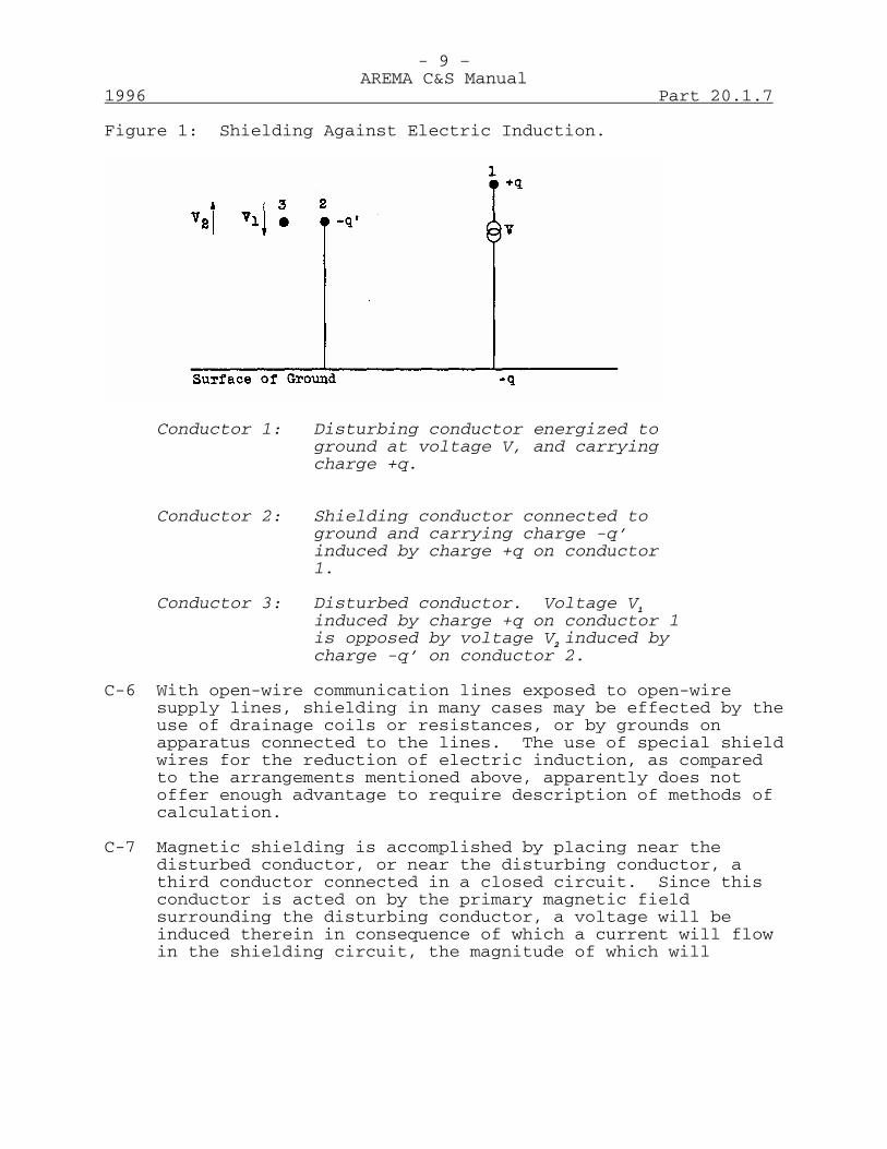
- 9 –AREMA C&S Manual
1996 Part 20.1.7
Figure 1: Shielding Against Electric Induction.
Conductor 1: Disturbing conductor energized toground at voltage V, and carryingcharge +q.
Conductor 2: Shielding conductor connected toground and carrying charge -q’induced by charge +q on conductor1.
Conductor 3: Disturbed conductor. Voltage V1
induced by charge +q on conductor 1is opposed by voltage V2 induced bycharge -q’ on conductor 2.
C-6 With open-wire communication lines exposed to open-wiresupply lines, shielding in many cases may be effected by theuse of drainage coils or resistances, or by grounds onapparatus connected to the lines. The use of special shieldwires for the reduction of electric induction, as comparedto the arrangements mentioned above, apparently does notoffer enough advantage to require description of methods ofcalculation.
C-7 Magnetic shielding is accomplished by placing near thedisturbed conductor, or near the disturbing conductor, athird conductor connected in a closed circuit. Since thisconductor is acted on by the primary magnetic fieldsurrounding the disturbing conductor, a voltage will beinduced therein in consequence of which a current will flowin the shielding circuit, the magnitude of which will
- 10 –AREMA C&S Manual
Part 20.1.7 1996
depend upon the voltage induced and upon the self-impedanceof this circuit. This current in the shielding conductorwill in turn induce in the disturbed conductor a voltage,the magnitude of which depends upon the magnitude of theshielding current and the coupling of shielding anddisturbed circuits. The phase relationship between thisshielding voltage and the voltage induced in the disturbedconductor by the primary field will depend upon the phaseangle of the shield self-impedance and upon that of themutual impedance of shielding and disturbed conductors. Foreffective shielding, the shielding voltage should be asnearly as possible equal and opposite to the voltageproduced by the disturbing conductor. Factors that favorthis condition are low impedance of the shielding circuit,large coupling between shielding and disturbed, or betweenshielding and disturbing conductors, and a high ratio ofinductive reactance to resistance in the shieldself-impedance and the mutual impedance of shield anddisturbed conductors.
C-8 The physical processes involved in magnetic shielding areillustrated by the simple system shown in Figure 2. With agiven current I1 in the disturbing circuit the voltagesinduced in the shielding circuit and in the disturbedcircuit, with the shielding circuit open are:
V2 = Z12I1 in shielding circuit (1)V3 = Z13I1 in disturbed circuit (2)
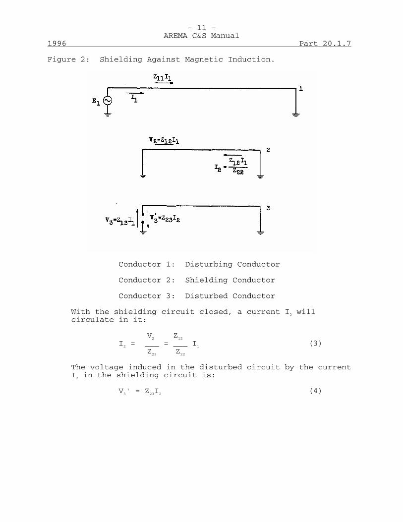
- 11 –AREMA C&S Manual
1996 Part 20.1.7
Figure 2: Shielding Against Magnetic Induction.
Conductor 1: Disturbing Conductor
Conductor 2: Shielding Conductor
Conductor 3: Disturbed Conductor
With the shielding circuit closed, a current I2 willcirculate in it:
V2 Z12
I2 = ___ = ___ I1 (3)Z22 Z22
The voltage induced in the disturbed circuit by the currentI2 in the shielding circuit is:
V3' = Z23I2 (4)
- 12 –AREMA C&S Manual
Part 20.1.7 1996
The total voltage in the disturbed circuit with theshielding circuit closed is:
Z12 Z23
V3" = V3 - V3' = Z13 (I - _) I1 (5)Z13 Z22
The shield factor • is then:
V3" Z12 Z23
• = = 1 - (6)V3 Z13 Z22
The impedances Z12, Z23, Z13 and Z22 are total mutual andself-impedances of the circuits designated by thesubscripts. When the circuits are uniform, parallel,coextensive* and of length s, and the shielding circuit isgrounded at the ends through resistances having a totalresistance R:
Z12 = sz12
Z13 = sz13
Z23 = sz23
Z22 = sz22 + R
where the lower case impedances are values per unit length,the shield factor then becomes:
Z12 Z23
• = 1 - (7)Z13(Z22 + R/s)
C-9 From equation (6) it is apparent that for a givenarrangement of disturbing, shielding, and disturbedconductors, the shield factor is unchanged when thepositions of the disturbing and disturbed conductors withrelation to the shielding conductor are interchanged. Inother words, the shield factor is the same whether Z23 ismade large and Z12 small by placing the shield close to thedisturbed conductor, or whether Z12 is made large and Z23
small by placing the shield close to the disturbing wire.This is shown graphically in Figure 3 by the symmetry of thecurves of shield factor versus position of shield conductor.
* The disturbing circuit or the disturbed circuit may extend beyond theother two circuits.
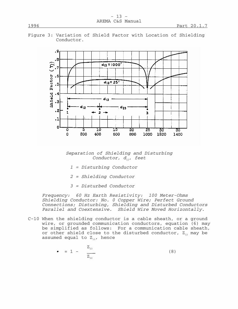
- 13 –AREMA C&S Manual
1996 Part 20.1.7
Figure 3: Variation of Shield Factor with Location of ShieldingConductor.
Separation of Shielding and DisturbingConductor, d12, feet
1 = Disturbing Conductor
2 = Shielding Conductor
3 = Disturbed Conductor
Frequency: 60 Hz Earth Resistivity: 100 Meter-OhmsShielding Conductor: No. 0 Copper Wire; Perfect GroundConnections; Disturbing, Shielding and Disturbed ConductorsParallel and Coextensive. Shield Wire Moved Horizontally.
C-10 When the shielding conductor is a cable sheath, or a groundwire, or grounded communication conductors, equation (6) maybe simplified as follows: For a communication cable sheath,or other shield close to the disturbed conductor, Z12 may beassumed equal to Z13, hence
Z23
• = 1 - _ (8)Z22
- 14 –AREMA C&S Manual
Part 20.1.7 1996
For a power cable sheath, or other shield close to thedisturbing conductor, Z13 may be assumed equal to Z23, hence.
Z12
• = 1 - (9)Z22
C-11 The variation of shield factor with the resistance andreactance of the shielding conductor will, for simplicity,be illustrated by considering the shield to consist of anaerial shield, such as a cable sheath, placed close to thedisturbed conductor and grounded at the ends. Theprinciples involved and the general conclusions apply to anyform of shield. Using total circuit impedances, the shieldfactor may be written as:
Z22 - Z23
• = (10)Z22
where Z22 = R' + (R22 + jX22) is the total earth returnself-impedance of the shield. R' is the dc resistance ofthe sheath plus grounds, and R22 - jX22 are, respectively, thereal (excluding the dc resistance) and imaginary componentsof the earth-return self-impedance of the sheath.
Z23 = (R23 - jX23) is the earth-return mutual impedance ofshield and disturbed conductors.
If the shield and the disturbed conductors are of the samelength, R22 = R23 approximately and X22 = X23 approximately:hence
R'• = approximately (11)
Z22
- 15 –AREMA C&S Manual
1996 Part 20.1.7
Equation (11) shows that the shield factor increases(shielding diminishes) as the dc resistance of the shieldincreases, and that it decreases with increasing shieldreactance.* Thus with aerial cables, for a given groundingresistance, the shield factor decreases as the size of thecable or the number of cables in parallel increases, or fora given cable, the shield factor decreases as the groundingresistance is reduced. For a given cable and groundingresistance, the shield factor may be reduced by placing tapearmor around the sheath, thus increasing its self-reactance.
Increasing the frequency increases sheath reactance: also anincreased reactance is associated with larger earthresistivity. Equation (11) therefore shows that the shieldfactor decreases with increasing frequency or increasingearth resistivity. To summarize: the shield factordecreases (shielding increases) when shield resistancedecreases, and the shield reactance, the frequency, and theearth resistivity increase.
If the disturbing, shielding and disturbed circuits areparallel and coextensive (the disturbing or disturbedcircuits may extend beyond the other two circuits), equation(11) may be written in terms of unit length impedances as:
r' + R/s• = (12)
Z22 + R/s
in which r' is the dc resistance per unit length of sheath,R is the total resistance of ground connections to thesheath and s is the length of the shielding circuit.Equation (12) indicates that the effect of a given totalgrounding resistance, R, is less the greater the length ofthe shielding circuit, and also that, under the givenconditions, little is to be gained by using a shieldingconductor of low resistance if it is not possible to securea low ratio of R's. Figures 4 to 7 illustrate these
* This statement is true only if whatever is done to increase the shieldreactance at the same time and by a proportionate amount increases themutual reactance of shield and disturbed conductor; this excludes(except in a special case) increasing the shield reactance by reactancecoils.
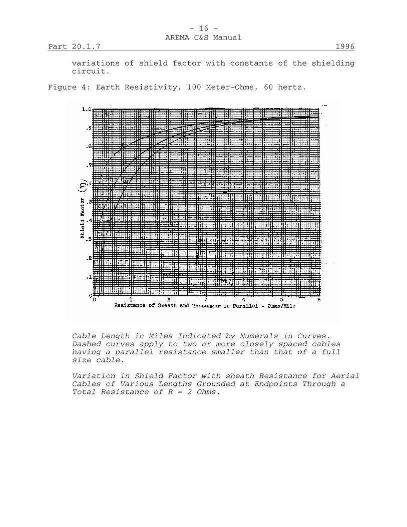
- 16 –AREMA C&S Manual
Part 20.1.7 1996
variations of shield factor with constants of the shieldingcircuit.
Figure 4: Earth Resistivity, 100 Meter-Ohms, 60 hertz.
Cable Length in Miles Indicated by Numerals in Curves.Dashed curves apply to two or more closely spaced cableshaving a parallel resistance smaller than that of a fullsize cable.
Variation in Shield Factor with sheath Resistance for AerialCables of Various Lengths Grounded at Endpoints Through aTotal Resistance of R = 2 Ohms.

- 17 –AREMA C&S Manual
1996 Part 20.1.7
Figure 5: Earth Resistivity: 100 Meter-Ohms
Ratio of Total Resistance of Endpoint Grounds in Ohms toLength of Cable in Miles indicated by Numbers on Curves
Variation in Shield with FrequencyFor Full-Size Aerial Cable Grounded at Endpoints

- 18 –AREMA C&S Manual
Part 20.1.7 1996
Figure 6: Frequency 60 Hz
Ratio of Total Resistance of Endpoint Grounds in Ohms toLength of Cable in Miles Indicated by Numerals on CurvesVariation in Shield Factor with Earth Resistivity ForFull-Size Aerial Cable Grounded at Endpoints.
C-12 While the discussion in the preceding paragraphs illustratesthe physical nature of magnetic shielding, and thecalculation of shielding in practical cases proceeds fromthe concepts set forth, it may be well to point out a numberof factors which may not be readily apparent. In the firstplace, the discussion has been limited to the effect ofshielding upon longitudinally induced voltages in circuits,such that no current flows along the conductor. Thiscondition is approximately satisfied in open-wire circuitsof moderate length and in cable circuits of short length,the length depending on the frequency in question: in thesecases, if the circuits are terminated in grounded
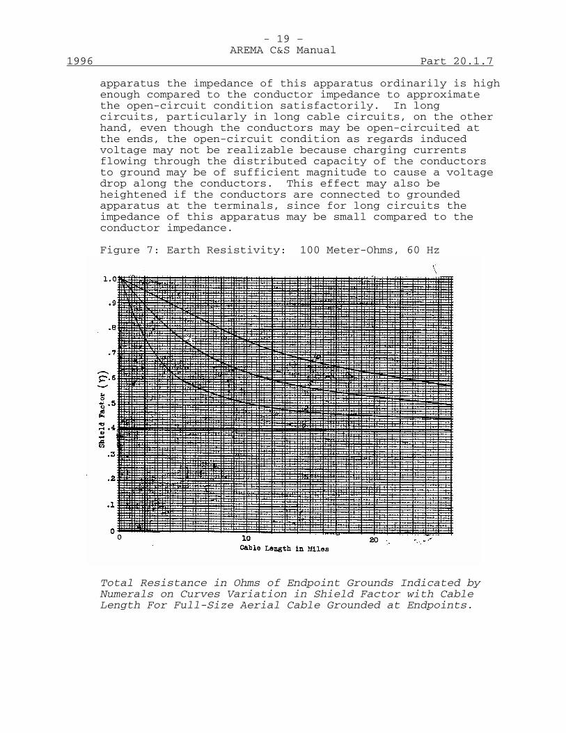
- 19 –AREMA C&S Manual
1996 Part 20.1.7
apparatus the impedance of this apparatus ordinarily is highenough compared to the conductor impedance to approximatethe open-circuit condition satisfactorily. In longcircuits, particularly in long cable circuits, on the otherhand, even though the conductors may be open-circuited atthe ends, the open-circuit condition as regards inducedvoltage may not be realizable because charging currentsflowing through the distributed capacity of the conductorsto ground may be of sufficient magnitude to cause a voltagedrop along the conductors. This effect may also beheightened if the conductors are connected to groundedapparatus at the terminals, since for long circuits theimpedance of this apparatus may be small compared to theconductor impedance.
Figure 7: Earth Resistivity: 100 Meter-Ohms, 60 Hz
Total Resistance in Ohms of Endpoint Grounds Indicated byNumerals on Curves Variation in Shield Factor with CableLength For Full-Size Aerial Cable Grounded at Endpoints.
- 20 –AREMA C&S Manual
Part 20.1.7 1996
Under these circumstances, shielding cannot be defined assimply as when circuits are short. For the long circuitcase, the calculation of shielding must take into accountthe propagation of voltage and current along the disturbedconductors and becomes a complicated process except in themore simple cases. For practical purposes, however, cableconductors can be regarded as being short if they do notexceed 25 miles for 60 hertz and 35 miles for 25 hertz.
C-13 In the discussion in Paragraph C-12, an aerial shield isused grounded only at the ends, and current in thedisturbing conductor is fed in one direction only. It isapparent that the equations given above will not apply ifthe shield contains intermediate grounds as well as terminalgrounds: because, in this case, the shield current is notconstant. If current in the disturbing wires is fed fromtwo directions, say from each end to a point inside theexposure, the equations above will apply to the netlongitudinal voltage if there are no intermediate shieldgrounds but not to voltage to ground. It is not practicableto attempt to give general equations for the many variableconditions of this kind that may be encountered. Theshielding in particular cases can usually be determined bystraightforward application of circuit theory.
C-14 In the case of a cable sheath that is continuously grounded,such as an underground cable, the calculation of shieldinginvolves propagation of voltage and current along the sheathand the shield factor is consequently a more complicatedfunction of the circuit configuration and constants. Theminimum shield factor obtainable for underground cables is:
r'• = (13)
Z22
in which the terms are as defined in equation (12). It willbe seen that equation (13) is obtained from equation (12)when R/s vanishes. This minimum shield factor is approachedin situations in which the underground cable, both theshield and the exposed conductors, extends for considerabledistances beyond each end of the exposure.
- 21 –AREMA C&S Manual
1996 Part 20.1.7
C-15 In the foregoing discussion, it has been taken for grantedthat there is no resistive coupling between the grounds towhich the induced voltage is referred and the grounds towhich the shield is connected: i.e., these grounds areassumed sufficiently far apart so that their mutualresistance is negligible. If such mutual resistance exists,it counteracts the effect of the shield groundingresistance: that is to say, the shield factor is reduced byit. In practical situations, no great amount of control canordinarily be exercised over the resistive coupling betweenground connections: its presence or absence is determined bylocal conditions. For example, in the case of a telephonecable sheath connected to a central office ground, the onlyground practically accessible for voltage reference at thecentral office may be the sheath or the same ground to whichthe sheath is connected. In this case, the resistance ofthe shield ground is mutual to the shielding and thedisturbed circuits, and the induced voltage is reduced by anamount equal to the drop across the shield groundresistance. The shield factor is thus smaller than it wouldbe if the voltage were referred to some other ground, inwhich case the voltage would exclude part or all of thisdrop, depending upon the mutual resistance between thegrounds. At a point on an aerial cable outside of thecentral office, on the other hand, the voltage betweenconductor and a ground other than the sheath ground, forexample a guy, may be of interest, in which case mutualresistance between the grounds would in general be muchsmaller than in the foregoing example.
C-16 The statement has been made that it is immaterial, asregards shield factor, whether the shielding conductor isplaced close to the disturbed conductor or close to thedisturbing conductor. While this statement is true asregards shield factor, it may not be true as regards theresulting induced voltage. Unless the separation betweenthe disturbing and disturbed conductors is usually small,placing the shield close to the disturbing conductor willtend to decrease the self-impedance of the latter to a muchgreater extent than if the shield is placed close to thedisturbed conductor. If the induced voltage results from agiven current in the disturbing conductor, as may be thecase under normal load conditions, this reaction of theshield upon the disturbing conductor will have no effectupon the net induced voltage in the disturbed circuit. Onthe other hand, if the induced voltage is produced by

- 22 –AREMA C&S Manual
Part 20.1.7 1996
current flowing to a fault on a power conductor, thiscurrent may be increased by the reaction of the shield uponthe disturbing wire, hence the net voltage induced in thedisturbed wire may be longer than if the shield were placedclose to the latter even though the shield factor may be thesame for the two cases.
C-17 Calculation of Shield Factor: Values of self and mutualimpedance for use in calculating shield factor may bedetermined from the charts of Figures 8-10, Tables C-1 toC-4, inclusive. These are taken from Engineering Report No.37 of the EEI-Bell System Joint Reports, Vol. IV. Thoroughstudy of the report is recommended.
C-18 Figure 8 and Tables C-1 to C-4, inclusive, provide the datanecessary for the determination of the 60 and 25 hertzself-impedance of an overhead wire with ground return. (Z22
of equation 8, Paragraph C-10, for example.) The formulafor self-impedance appears on Figure 8, together with curvesgiving the reactive component (X11) as a function ofconductor diameter, for several values of earth resistivity.The effective resistance (R) and the internal reactance(K), which must be added, are shown in Tables C-1 to C-4inclusive.
C-19 Calculation of shield factor also requires the use of themutual impedance between, for example, the disturbedconductor and the shield (Z23 of equation 8, Paragraph C-10).This may be derived conveniently from the curves of Figures9 and 10, for 60 Hz and 25 Hz, respectively. The mutualimpedance is plotted as a function of the separation betweenthe two conductors, for a range of earth resistivities.
C-20 The self and mutual impedances derived as outlined above,and employed in equations 8 and 9 of Paragraph C-10 willsuffice in such problems as determining the shielding effectof a lead cable sheath on the internal conductors, theeffect of a shield wire on the communication line or thecalculation of the percent earth current as affected by themulti-grounded neutral conductor on a single-phasedistribution line.
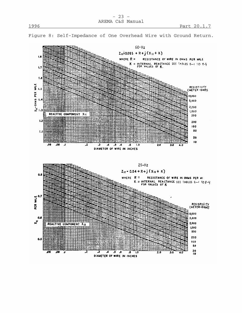
- 23 –AREMA C&S Manual
1996 Part 20.1.7
Figure 8: Self-Impedance of One Overhead Wire with Ground Return.

- 24 –AREMA C&S Manual
Part 20.1.7 1996
Figure 9: 60-Hz Mutual Impedance of Two Overhead Wires withGround Return.
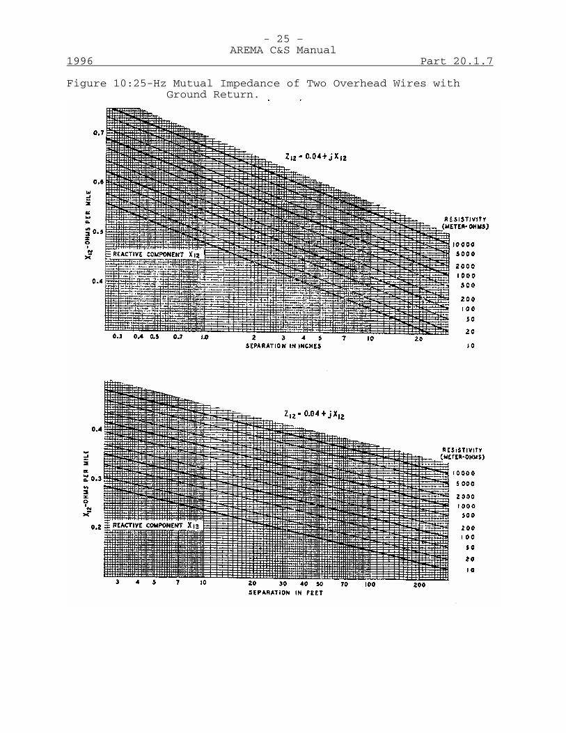
- 25 –AREMA C&S Manual
1996 Part 20.1.7
Figure 10:25-Hz Mutual Impedance of Two Overhead Wires withGround Return.

- 26 –AREMA C&S Manual
Part 20.1.7 1996
Table C-1EFFECTIVE RESISTANCE OF HARD-DRAWN STRANDED COPPER CONDUCTORS
Taken in part from Table 26, page 421, of "SymmetricalComponents: by C. F. Wagner and R. D. Evans.
For a temperature of +50°C, 25°C rise above +25°C ambient.
Effective Resistance (ohms per mile)
Size of Conductor Circular mils
AWG
Outside
Diameter (Inches)
60 Hz
25 Hz
1,000,000
---
1.152
0.0685
0.0648
950,000
---
1.123
.0718
.0683 900,000
---
1.093
.0752
.0718
850,000
---
1.062
.0794
.0761 800,000
---
1.031
.0837
.0806
750,000
---
0.998
.0888
.0860 700,000
---
.964
.0947
.0920
650,000
---
.929
.0997
.0991 600,000
---
.891
.1090
.1070
550,000
---
.853
.1194
.1173 500,000
---
.814
.1300
.1280
450,000
---
.772
.1446
.1429 400,000
---
.725
.1620
.1600
350,000
---
.679
.1849
.1835 300,000
---
.628
.215
.214
250,000
---
.574
.257
.256 211,600
0000
.528
.303
.303
211,600
0000
.522
.303
.303 167,806
000
.464
.382
.381
133,077
00
.414
.481
.481 105,535
0
.368
.607
.606
83,693
1
.328
.765
.765 66,371
2
.292
.964
.964
52,635
3
.260
1.22
1.22 41,741
4
.232
1.53
1.53
33,102
5
.206
1.93
1.93 26,251
6
.184
2.44
2.44
The internal reactance (K) of copper conductors depends on thestranding. Values applicable to the usual strandings for wiresizes in the above table are:
Internal Reactance (K) (ohms per mile)
Size of Conductor
Circular mils
Number of
Strands 60 Hz
25 Hz
25,251 to 211,600
7
0.039
0.016
211,600 to 400,000
19
.033
.014
450,000 to 600,000
37
.032
.013
650,000 to 1,000,000
61
.031
.013
All sizes
solid
.031
.013
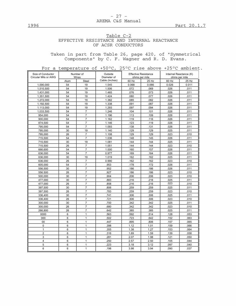
- 27 –AREMA C&S Manual
1996 Part 20.1.7
Table C-2EFFECTIVE RESISTANCE AND INTERNAL REACTANCE
OF ACSR CONDUCTORS
Taken in part from Table 26, page 420, of "SymmetricalComponents" by C. F. Wagner and R. D. Evans.
For a temperature of +50°C, 25°C rise above +25°C ambient.
Number of Wires
Effective Resistance
ohms per mile
Internal Reactance (K)
ohms per mile
Size of Conductor
Circular Mils or AWG Alum
Steel
Outside
Diameter of Cable (Inches)
60 Hz
25 Hz
60 Hz
25 Hz
1,590,000
54
19
1.545
0.068
0.066
0.026
0.011 1,510,500
54
19
1.506
.072
.069
.026
.011
1,431,000
54
19
1.465
.076
.073
.026
.011 1,351,500
54
19
1.424
.080
.077
.026
.011
1,272,000
54
19
1.382
.085
.082
.026
.011 1,192,500
54
19
1.338
.091
.087
.026
.011
1.113,000
54
19
1.293
.097
.094
.026
.011 1,033,500
54
7
1.246
.104
.101
.026
.011
954,000
54 7
1.196
.113
.109
.026
.011
900,000
54 7
1.162
.119
.116
.026
.011
874,500
54 7
1.146
.123
.119
.026
.011
795,000
54 7
1.093
.138
.131
.026
.011
795,000
30
19
1.140
.129
.129
.025
.011 795,000
26
7
1.108
.129
.129
.023
.010
715,500
54 7
1.036
.148
.145
.026
.011
715,500
30
19
1.081
.144
.144
.025
.011 715,500
26
7
1.051
.144
.144
.023
.010
666,600
54 7
1.000
.160
.157
.026
.011
636,000
54 7
0.977
.169
.164
.026
.011
636,000
30
19
1.019
.162
.162
.025
.011 636,000
26
7
0.990
.162
.162
.023
.010
605,000
54 7
.953
.178
.172
.026
.011
556,500
30 7
.952
.186
.186
.026
.011
556.500
26 7
.927
.186
.186
.023
.010
500,000
30 7
.904
.206
.206
.023
.010
477,000
30 7
.883
.216
.216
.025
.011
477,000
26 7
.858
.216
.216 .023
.010
397,500
30 7
.806
.259
.259
.025
.011
397,500
26 7
.783
.259
.259
.023
.010
336,400
30 7
.741
.306
.306
.025
.011
336,400
26 7
.721
.306
.306
.023
.010
300,000
30 7
.700
.342
.342
.025
.011
300,000
26 7
.680
.342
.342
.023
.010
266,800
26 7
.642
.385
.385
.025
.011
0000
6 1
.563
.592
.514
.128
.053
000
6 1
.502
.723
.642
.152
.063
00
6 1
.447
.895
.806
.157
.065
0
6 1
.398
1.12
1.01
.159
.066
1
6 1
.355
1.38
1.27
.153
.064
2
6 1
.316
1.69
1.59
.139
.058
3
6 1
.281
2.07
1.98
.121
.050
4
6 1
.250
2.57
2.50
.105
.044
5
6 1
.223
3.18
3.12
.097
.040
6
6 1
.198
3.98
3.94
.090
.037
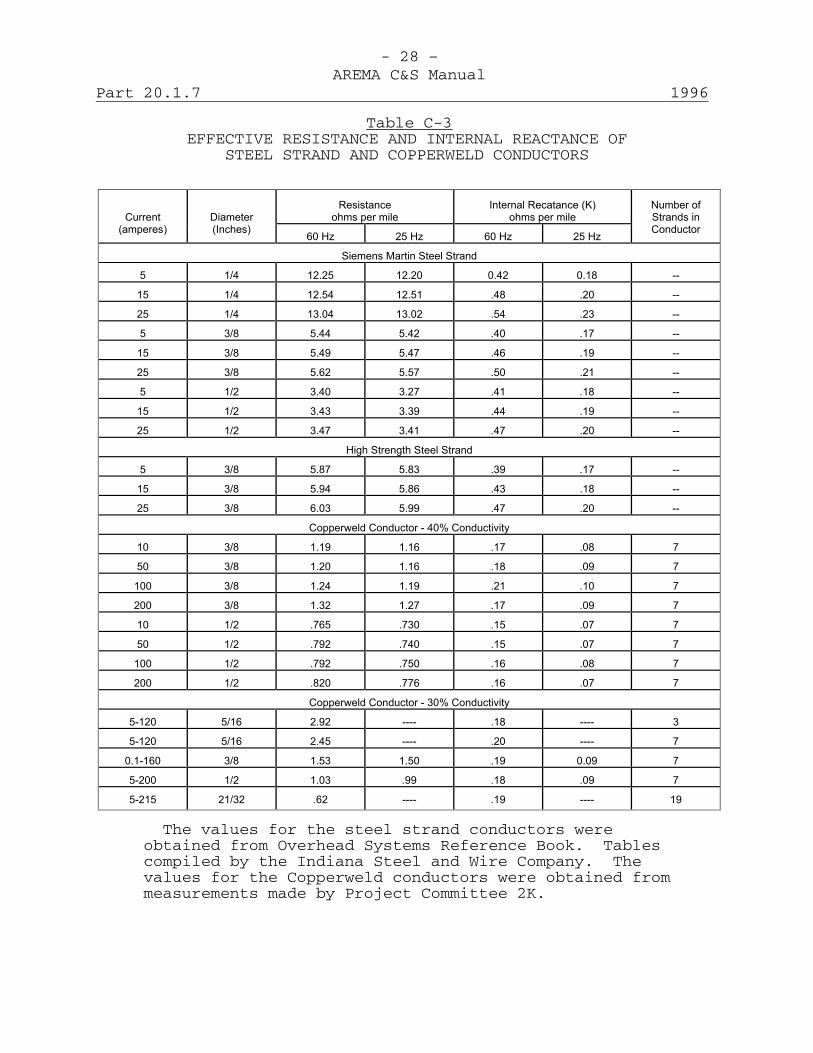
- 28 –AREMA C&S Manual
Part 20.1.7 1996
Table C-3EFFECTIVE RESISTANCE AND INTERNAL REACTANCE OF
STEEL STRAND AND COPPERWELD CONDUCTORS
Resistance ohms per mile
Internal Recatance (K)
ohms per mile
Current (amperes)
Diameter (Inches)
60 Hz
25 Hz
60 Hz
25 Hz
Number of Strands in Conductor
Siemens Martin Steel Strand
5
1/4
12.25
12.20
0.42
0.18
--
15
1/4
12.54
12.51
.48
.20
--
25
1/4
13.04
13.02
.54
.23
--
5
3/8
5.44
5.42
.40
.17
--
15
3/8
5.49
5.47
.46
.19
--
25
3/8
5.62
5.57
.50
.21
--
5
1/2
3.40
3.27
.41
.18
--
15
1/2
3.43
3.39
.44
.19
--
25
1/2
3.47
3.41
.47
.20
--
High Strength Steel Strand
5
3/8
5.87
5.83
.39
.17
--
15
3/8
5.94
5.86
.43
.18
--
25
3/8
6.03
5.99
.47
.20
--
Copperweld Conductor - 40% Conductivity
10
3/8
1.19
1.16
.17
.08
7
50
3/8
1.20
1.16
.18
.09
7
100
3/8
1.24
1.19
.21
.10
7
200
3/8
1.32
1.27
.17
.09
7
10
1/2
.765
.730
.15
.07
7
50
1/2
.792
.740
.15
.07
7
100
1/2
.792
.750
.16
.08
7
200
1/2
.820
.776
.16
.07
7
Copperweld Conductor - 30% Conductivity
5-120
5/16
2.92
----
.18
----
3
5-120
5/16
2.45
----
.20
----
7
0.1-160
3/8
1.53
1.50
.19
0.09
7
5-200
1/2
1.03
.99
.18
.09
7
5-215
21/32
.62
----
.19
----
19
The values for the steel strand conductors wereobtained from Overhead Systems Reference Book. Tablescompiled by the Indiana Steel and Wire Company. Thevalues for the Copperweld conductors were obtained frommeasurements made by Project Committee 2K.

- 29 –AREMA C&S Manual
1996 Part 20.1.7
Table C-4DC RESISTANCE OF LEAD CABLE SHEATH
Resistances are computed for a resistivity of 20 x 10-6 ohmsper centimeter cube at + 25°C or + 77°F.
Note: 1. The internal reactance (K) may be takenas zero for lead cable sheaths.
2. Lead cable is not recommended dueto environmental hazards andregulations, but is given here forreference.
C-21 When the disturbing (or disturbed) circuit consists ofseveral conductors, as in the case of a three-phase line,where the shield factor is most commonly used to evaluatethe shielding afforded by the overhead ground wire duringphase-to-ground faults, it is convenient to use the methodof geometric mean separations. This is particularly sosince the fault may occur on any of the three conductors,and separate evaluations of shield factor are not justified.In this approach, the geometric mean separation is used indetermining the value of the mutual impedance.
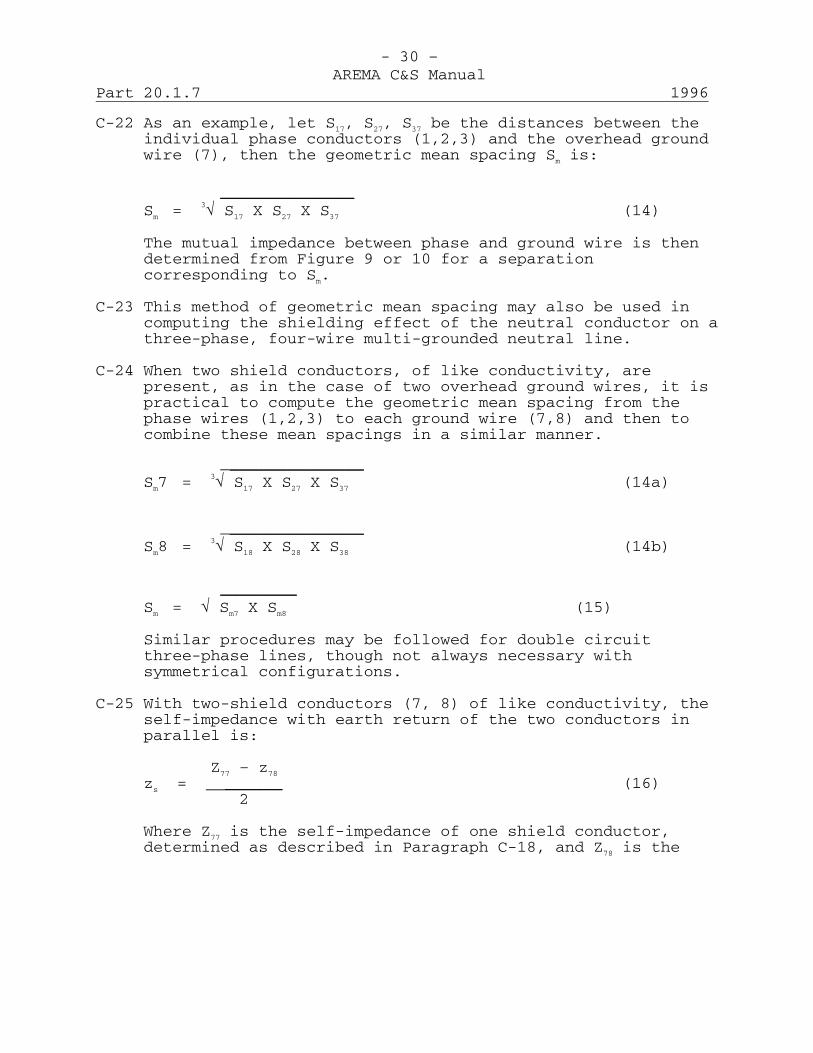
- 30 –AREMA C&S Manual
Part 20.1.7 1996
C-22 As an example, let S17, S27, S37 be the distances between theindividual phase conductors (1,2,3) and the overhead groundwire (7), then the geometric mean spacing Sm is:
______________Sm = 3√ S17 X S27 X S37 (14)
The mutual impedance between phase and ground wire is thendetermined from Figure 9 or 10 for a separationcorresponding to Sm.
C-23 This method of geometric mean spacing may also be used incomputing the shielding effect of the neutral conductor on athree-phase, four-wire multi-grounded neutral line.
C-24 When two shield conductors, of like conductivity, arepresent, as in the case of two overhead ground wires, it ispractical to compute the geometric mean spacing from thephase wires (1,2,3) to each ground wire (7,8) and then tocombine these mean spacings in a similar manner.
_______________Sm7 = 3√ S17 X S27 X S37 (14a)
_______________Sm8 = 3√ S18 X S28 X S38 (14b)
________Sm = √ Sm7 X Sm8 (15)
Similar procedures may be followed for double circuitthree-phase lines, though not always necessary withsymmetrical configurations.
C-25 With two-shield conductors (7, 8) of like conductivity, theself-impedance with earth return of the two conductors inparallel is:
Z77 – z78
zs = ______ (16)2
Where Z77 is the self-impedance of one shield conductor,determined as described in Paragraph C-18, and Z78 is the
- 31 –AREMA C&S Manual
1996 Part 20.1.7
mutual impedance between shield conductors as described inParagraph C-19, and obtained from Figures 9 or 10.
C-26 The shield factor for two ground wires, then is, derivedfrom equation 9 of Paragraph C-10 by substitution of theproper values:
2 Z17
• = 1 - ______ (16)z77 + z78
Where Z17 is the mutual impedance between phase-wire groupsand ground-wire groups, at a spacing corresponding to Sm
(equation 15).
D-Balance of Power and Communication Circuits
D-1 In discussing balance of power and communication circuits,it is convenient to distinguish between (1) line unbalancesand (2) apparatus, equipment or load unbalances. Ingeneral, in the following, the word "circuit" is used tomean the line-part of the complete circuit, withoutinclusion of loads or apparatus. It is believed that noconfusion will arise from the occasional use of the word ina broader sense, the context being sufficient to make themeaning clear in such cases.
Balance of Supply CircuitsD-2 A supply circuit is balanced if the normally energized
conductors belonging to it have equal self-impedances andadmittances to ground and equal impedances and admittancesto each other and to all neighboring conductors, in eachelementary section of the length of the circuit. This isequivalent to saying that, in a balanced circuit, theconductors that are regularly energized, when the circuit isin use as designed, possess the property of electricalsymmetry in any short section of the circuit. It is notnecessary that any two of the sections should be alike: thatis, for example, the various electrical characteristics(impedances and admittances) of the normally energizedconductors may be different, in one mile of line, from whatthey are in another; but in each of these miles, consideredby itself, the property of electrical symmetry must obtainamong all of the normally energized conductors in that mile,if the circuit is balanced.
- 32 –AREMA C&S Manual
Part 20.1.7 1996
D-3 The use of the adjective "elementary" (or "short") in theabove definition means, strictly, that in applying thecriterion of electrical symmetry the length of section to betaken is to be allowed to approach zero as a limit. While,theoretically, this might make the criterion easier to meet,this is of no importance practically, since all actual linesare more or less unbalanced, and the unbalances areapproximately compensated, where necessary and practicable,by transpositions. Thus for practical purposes, the"elementary" section may often be a transposition section.Technically speaking, the length of such a section should bea comparatively small fraction of the wavelength of thehighest frequency deemed to be of interest. Also, in orderto include the case (discussed below) of branches havingfewer than the total number of phase-conductors, an"elementary" section of the main circuit in the vicinity ofsuch a branch must be considered to include the branchconnections. It should be noticed that in the abovedefinition of a balanced supply circuit, the characteristicsof the circuit as regards balance do not depend upon the wayin which the circuit is energized: nor does the presence ofresidual currents or voltages in a supply circuitnecessarily mean that the circuit is unbalanced, since suchresiduals may be the result of the mode of energization, orof loading. It is also important to notice that the termsbalanced and unbalanced, when used in describing thecondition of a supply circuit with respect to electricalsymmetry among its conductors, are used in a different sensefrom that in which they are used in describing the currentsand voltages of the conductors of the circuit. It isevident that such a property, or the lack of it, is notamong the characteristics of the wires to which the currents(or voltages) belong. The opposite of "balanced," when oneis talking about currents or voltages, is "residual," not"unbalanced", although it is true that residual current, forexample, is sometimes (inappropriately) called "unbalanced"current. Also, a ground-return circuit is sometimes said tobe "wholly unbalanced." It is preferable to speak of itsimply as a ground-return circuit.
D-4 It is a characteristic of a balanced circuit that if it isenergized in a balanced manner and if the loads are alsobalanced or have no connection to neutral or to ground, noresiduals will result. On the other hand, residuals are ingeneral produced if an unbalanced circuit is energized,

- 33 –AREMA C&S Manual
1996 Part 20.1.7
even with balanced voltages, or if a balanced circuit isenergized with voltages containing residual components. Infact, since it is impossible to build electrical machineryhaving identical characteristics for all phases, and sinceit is equally impossible to construct perfectly balancedlines, residuals are necessarily present in actual lines forboth reasons. Practically, it is simply a question of theirmagnitudes. As has been previously pointed out, thecoupling between a supply and a neighboring communicationcircuit is usually much larger for ground-return residualsthan for balanced components. While the former, for thisreason, are frequently the more important in coordinationproblems, situations are by no means uncommon in whichbalanced components are of controlling importance.
D-5 In an ungrounded system, the voltages to ground are largelydetermined by the capacitances to earth of each phase of thewhole system. If these are unequal, a residual voltage isproduced. Transposition of the phase wires tends toequalize these capacitances to ground and to reduce residualvoltages. In general, residual voltage due to circuitunbalances will be lower with a grounded neutral system thanwith an isolated system, since with the former, linecapacitances to ground are shunted by transformerimpedances. However, the presence of these lower impedancepaths to ground tends to increase the residual currents.
D-6 In considering the matter of supply circuit balance asherein defined, it must be recognized that other factors,such as wave shape or methods of operation, may he ofgreater importance in contributing to inductive influence.This does not mean that circuit balance is not an importantfactor, but that in certain cases more can be accomplishedin the control of inductive effects through the control ofother factors.
D-7 For the purpose of this discussion it will be convenient todivide supply circuits into two classes: namely,transmission circuits and distribution circuits. Thedistinction assumed between these two classes of circuits isthat transmission circuits may be thought of as transmittingpower in bulk between specified points, as from a generatingstation to a substation which may be located at some distantpoint, whereas distribution circuits may be thought of ascircuits which carry the power from the substation to thecustomers or points of
- 34 –AREMA C&S Manual
Part 20.1.7 1996
utilization located in a generally limited adjacent area.Under this classification transmission circuits may bethought of as generally operating at a voltage higher thandistribution circuits. However, transmission circuits maybe operated at voltages as low as 6600 volts, while undercertain conditions circuits operating at voltages as high as22,000 volts may be classed as distribution circuits.Transmission circuits are more or less permanent when onceestablished, whereas distribution circuits are subject today-by-day changes and extensions. Another distinction isthat a transmission circuit generally includes the fullnumber of phase wires throughout its length, whereas adistribution circuit is commonly made up of a main feederand numerous branches some of which may consist of less thanthe full number of phase wires.
D-8 The principal factors affecting the impedance or admittanceunbalance of a supply circuit are:(a) Configuration including phase arrangement on twin
circuit lines.
(b) Transpositions.
(c) The distribution among the various phases of branchesconsisting of less than the total number of phasewires.
D-9 Configuration is defined as "The geometrical arrangement intransverse section of any assemblage of generally parallelconductors including their size and their relative positionswith respect to other conductors and to the earth." (SeeC&S Manual Part 20-1-4 (Recommended Principles and Practicesfor the Inductive Coordination of Railway Electrical SupplyFacilities and the Commercial Communication Facilities)).Aside from its effect upon induction from balancedcomponents, the configuration of a supply line is ofinterest because of its relation to admittance unbalance andimpedance unbalance. As to admittance unbalance,configuration affects this only through its effects uponcapacitance unbalance since, of course, it has no directeffect upon leakage.
D-10 The capacitances to ground and the mutual impedances of thenormally energized conductors of a supply circuit areaffected by their relative heights above ground, theirspacing and by other conductors located on the same orclosely adjacent lines. In discussing the effect of
- 35 –AREMA C&S Manual
1996 Part 20.1.7
configuration on balance, therefore, it is necessary toconsider it from two points of view: namely theconfiguration of the normally energized conductors of thesupply circuit itself, and the configuration of the line asa whole, as defined in Paragraph D-9. Where the linecarries only the normally energized conductors, as in thecase of a three-wire three-phase line, the two points ofview become the same. In general, however, other wires arepresent on the line in various combinations and thefollowing shows typical examples of the various conditionsthat may be met:1. Single circuit lines that carry only the wires to be
energized: the circuits may be two-wire single-phase orthree-wire three-phase.
2. Single circuit lines, as described in (1) but with theaddition of overhead ground wire or wires.
3. Multi-circuit lines in which the several circuits areof the same voltage and are energized from the samesource. Such lines are often spoken of as twin circuitlines, triple circuit lines, etc., depending on thenumber of circuits carried. Such multi-circuit linesmay or may not also carry overhead ground wires.
4. Single or multi-circuit lines in which the circuits aremade up of more than the normally energized conductors,as for instance, three-phase four-wire circuits.
5. Lines carrying combinations of one or more circuits, asdescribed in (1) to (4) with other circuits ofdifferent voltage or frequency. One specific examplewould be a line carrying a 22,000-volt circuit, a4,000-volt distribution circuit and a 220-voltsecondary circuit.
6. Lines carrying both supply and communication circuits.
D-11 Transmission circuits are generally carried on lines of thetypes described in (1), (2) and (3) in Paragraph D-10.Distribution circuits, on the other hand, are generallycarried on lines of the type described in (4), (5) and (6)in Paragraph D-10.
- 36 –AREMA C&S Manual
Part 20.1.7 1996
D-12 While the configuration of a circuit has a considerableeffect on its balance if it is un-transposed, it isfrequently the case that the residual voltage and groundreturn currents are more dependent on the method ofenergization, the method of connecting and the amount andtype of load carried and (for distribution circuits) onsingle-phase branches, than on configuration. Furthermore,in cases where the capacitance unbalance due toconfiguration is important, it can under certain conditionsbe reduced by power circuit transpositions as discussed inParagraphs D-23 to D-25. Since the configuration employedis often largely determined by structural and insulationconsiderations, there are many cases where it is not subjectto adjustment for inductive coordination reasons alone.Where there is a choice of configuration, it is helpful toemploy the one that will provide the superior balance.
D-13 For a single three-phase transmission circuit carried on aline of the type described in (1) of Paragraph D-10,symmetrical configurations have in general less admittanceunbalance than unsymmetrical configurations. Of the varioussymmetrical configurations, the triangular has the lowestcapacitance unbalance to ground, the equally spaced verticaland equally spaced horizontal configurations having muchhigher and about equal capacitance unbalances to ground.For one single-phase circuit carried on such a line, ahorizontal configuration has less unbalance than all otherarrangements.
D-14 The unbalance incident to configuration results in aresidual voltage when the circuit is energized with balancedvoltages from an ungrounded source. If the line section isshort and un-transposed, and balanced voltages, equal inmagnitude to the nominal voltage of the circuit, are appliedbetween the phase-conductors, the resulting residual voltageis called the characteristic residual voltage of thecircuit. The characteristic residual voltage is frequentlyexpressed as a percentage of the nominal phase-to-phasevoltage of the circuit. Thus expressed, it depends only onthe configuration, Figures 11 and 12 show calculatedcharacteristic residual voltages (in kilovolts) for singlecircuit lines, for a number of configurations, with variousheights and voltages of energization with conductor spacingsas shown in Table D-1. To use the curves, find the firstcolumn of Table D-1, the
- 37 –AREMA C&S Manual
1996 Part 20.1.7
line voltage corresponding to the configuration and spacingof the actual line for which the characteristic residualvoltage is desired. Locate this voltage on the horizontalscale of Figures 11 (or 12). The intersection of theordinate, passing through this point so located, with thecurve corresponding to the configuration and height aboveground of the actual line, gives directly, on the verticalscale, the desired characteristic residual voltage, providedthe actual line voltage is the same as the line voltagetaken from Table D-1. If these two line voltages are notthe same, the result read on the vertical scale, asdescribed, must be multiplied by the ratio
actual line voltage__voltage from table D-1
to get the characteristic residual voltage of the line inquestion.
D-15 Where overhead ground wires are added to single circuitlines as described in (2) of Paragraph D-10, the situationmay be considerably changed. For a three-phase circuit thepreferable configuration from the standpoint of balance willdepend upon the number and relative location of the groundwires with respect to the phase wires. Under certainconditions where a single ground wire is used, the invertedtriangle, or where two ground wires are used, thesymmetrical horizontal may be preferable. For the singlephase circuit the horizontal configuration will generally bepreferable.
D-16 In the case of multi-circuit lines, as described in (3) ofParagraph D-10, such a variety of conditions arise that eachcase must be considered individually. In such cases,however, more can often be accomplished in limiting theinductive influence of the lines by suitable phaseinterconnection of the circuits than by attempting to selectthe optimum configuration. Figures 13 and 14 give somecalculated data regarding the characteristic residualvoltage (Erc), in percentage of the phase-to-phase voltage,for twin-circuit three-phase lines. It will be noted thatthe dimensions given contain no reference to a unit oflength, ERC depending only on the relative magnitudes of thevarious dimensions. Figure 13 covers certain twin circuitconfigurations without ground wires, for different methodsof interconnecting the conductors of the two circuits.
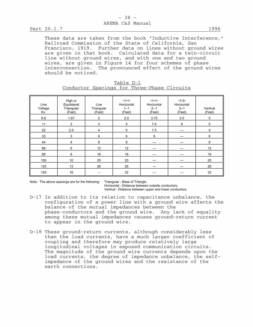
- 38 –AREMA C&S Manual
Part 20.1.7 1996
These data are taken from the book "Inductive Interference,"Railroad Commission of the State of California, SanFrancisco, 1919. Further data on lines without ground wiresare given in that book. Calculated data for a twin-circuitline without ground wires, and with one and two groundwires, are given in Figure 14 for four schemes of phaseinterconnection. The pronounced effect of the ground wiresshould be noticed.
Table D-1Conductor Spacings for Three-Phase Circuits
Line Voltage
Kv.
High or
Equilateral Triangular
(Feet)
Low Triangular
(Feet)
�1�1�
Horizontal 1--1
(Feet)
�1�1�
Horizontal 2--1
(Feet)
�1�3�
Horizontal 3--1
(Feet)
Vertical (Feet)
6.6
1.67
2
2.5
3.75
5.0
5
11
2
3
5
7.5
9
5
22
2.5
4
5
7.5
---
5
33
3
6
6
9
---
6
44
4
8
8
---
---
8
66
6
12
12
---
---
12
88
8
16
16
---
---
16
100
10
20
20
---
---
20
125
13
26
26
---
---
26
150
16
--
32
---
---
32
Note: The above spacings are for the following: Triangular - Base of Triangle.
Horizontal - Distance between outside conductors. Vertical - Distance between upper and lower conductors.
D-17 In addition to its relation to capacitance unbalance, theconfiguration of a power line with a ground wire affects thebalance of the mutual impedances between thephase-conductors and the ground wire. Any lack of equalityamong these mutual impedances causes ground-return currentto appear in the ground wire.
D-18 These ground-return currents, although considerably lessthan the load currents, have a much larger coefficient ofcoupling and therefore may produce relatively largelongitudinal voltages in exposed communication circuits.The magnitude of the ground wire currents depends upon theload currents, the degree of impedance unbalance, the self-impedance of the ground wires and the resistance of theearth connections.
- 39 –AREMA C&S Manual
1996 Part 20.1.7
D-19 On single-circuit lines the configuration is the principalfactor determining the impedance unbalance. On linescarrying more than one circuit, certain interconnections ofthe various phase wires may result in considerable decreasein the unbalance. Figure 15 shows the impedance unbalanceon three representative types of twin-circuit lines with oneand two ground wires, showing the effects of variousinterconnections of the Phase wires. The configurations inthe top and bottom rows are the same as in Figure 14. Thelines are assumed to be carrying equal and symmetricalloads.
D-20 Circuits carried on lines of the types described in (4) and(6) of Paragraph D-10, generally fall under theclassification of distribution circuits. In the case ofthree-phase four-wire circuits having single ormulti-grounded neutral, the neutral conductor is frequentlygrouped with the phase conductors, and the optimumconfiguration will depend upon the arrangements employed,the presence of other conductors and whether or not suchconductors are grounded. For this class of circuit theeffects of load balance, distribution of branches, etc., maybe far more important from the inductive standpoint than thebalance of the circuit, or circuits, as defined in thisdiscussion.
D-21 For lines of the type described in (5) of Paragraph D-10, itis necessary to consider the configuration of the line as awhole. Here again, the inductive effects resulting from themethods of operation, particularly of the intermediatevoltage circuits and the distribution of branches, etc., arefrequently of much greater importance than the configurationof either the line or the transmission circuit.
D-22 From the above, it is evident that the effect ofconfiguration on supply circuit balance is of importancemainly in connection with transmission circuits. Quite,commonly, in the case of distribution circuits and in somecases of transmission circuits, the effects of other factorson inductive influence are so much greater thatconfiguration becomes a secondary matter. In certain cases,configuration may, of course, have an important bearing oninduction from balanced components. In some cases, theconfiguration that is preferable from the standpoint ofinduction from balanced components, is not

- 40 –AREMA C&S Manual
Part 20.1.7 1996
preferable from the standpoint of circuit balance. In suchcases, it is necessary either to select the configurationaccording to whether it is more desirable to controlinduction from residuals or from balanced components, or tomake a compromise between the two.
D-23 Transpositions: The capacitance unbalance to groundincident to the configuration of a supply circuit cantheoretically be brought to a condition of approximatebalance by systematically interchanging the conductorsbetween the conductor positions so that each normallyenergized conductor occupies each conductor position for anequal distance, that is, by the proper use oftranspositions.
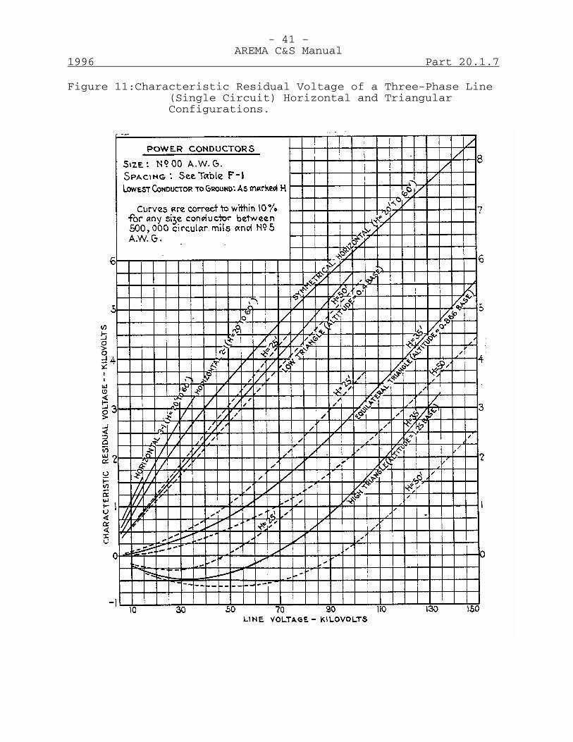
- 41 –AREMA C&S Manual
1996 Part 20.1.7
Figure 11:Characteristic Residual Voltage of a Three-Phase Line(Single Circuit) Horizontal and TriangularConfigurations.

- 42 –AREMA C&S Manual
Part 20.1.7 1996
Figure 12:Characteristic Residual Voltages of a Three-Phase Line(Single Circuit) Vertical Configurations.
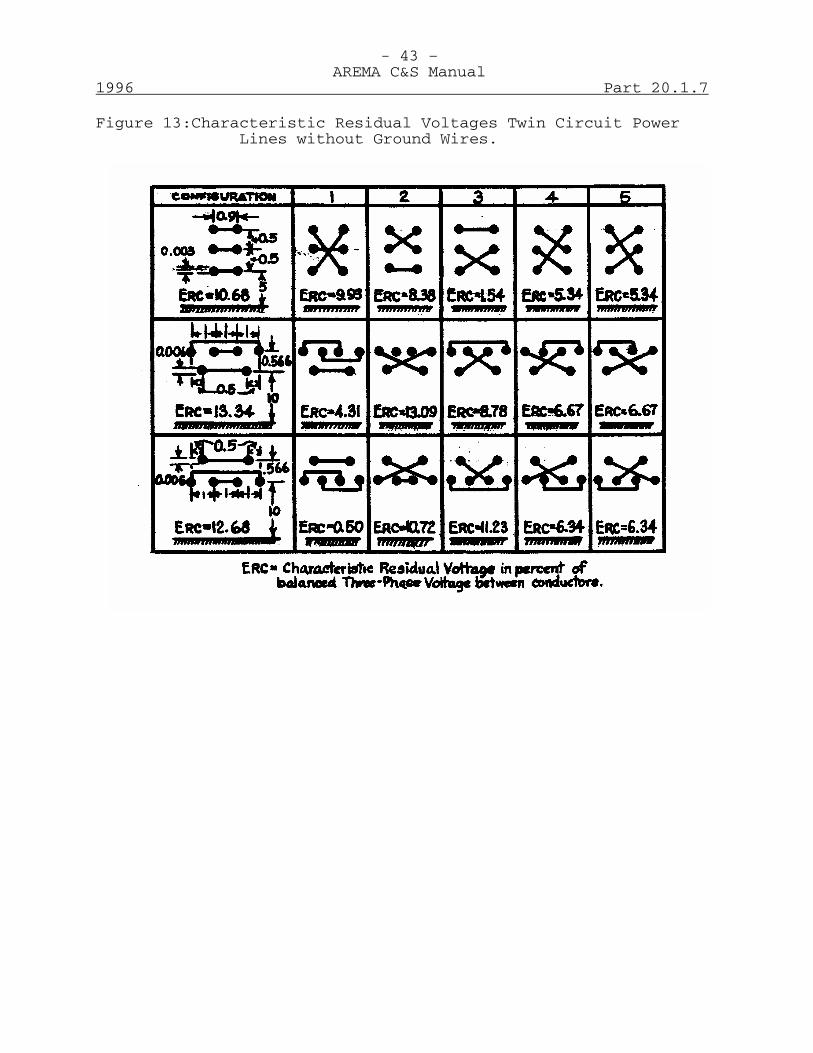
- 43 –AREMA C&S Manual
1996 Part 20.1.7
Figure 13:Characteristic Residual Voltages Twin Circuit PowerLines without Ground Wires.
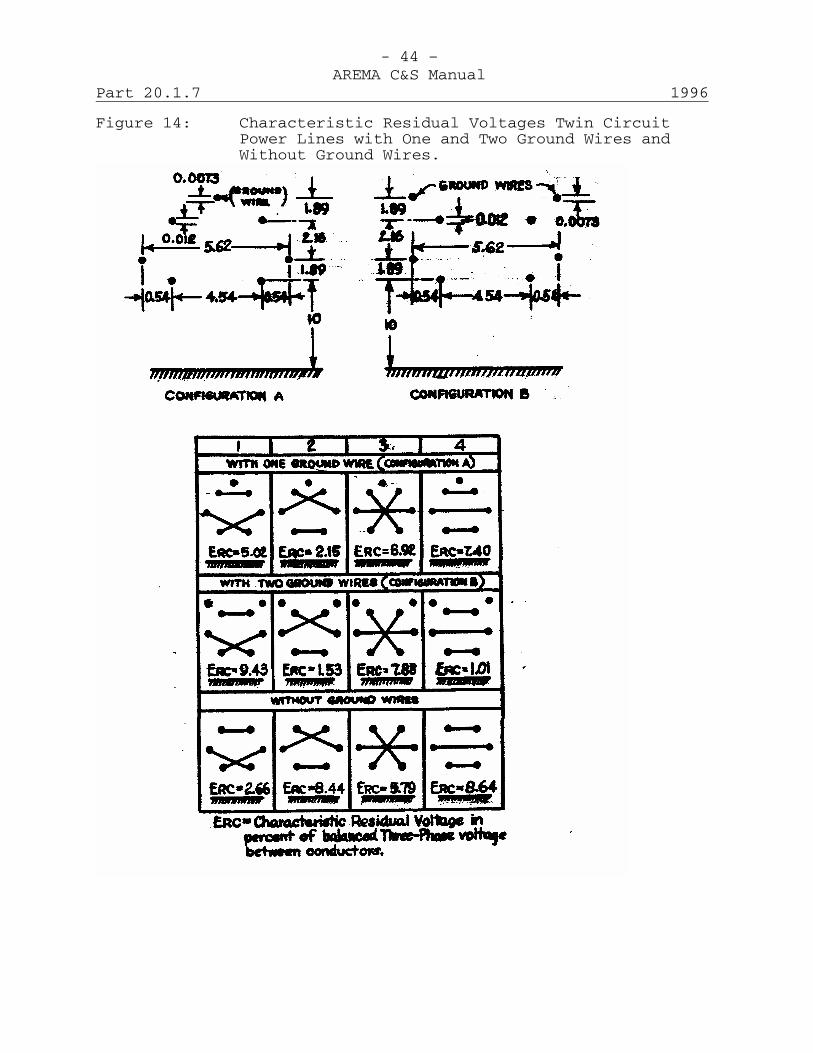
- 44 –AREMA C&S Manual
Part 20.1.7 1996
Figure 14: Characteristic Residual Voltages Twin CircuitPower Lines with One and Two Ground Wires andWithout Ground Wires.

- 45 –AREMA C&S Manual
1996 Part 20.1.7
Figure 15: Examples of Impedance Unbalance Between PhaseConductors and Ground Wires for DifferentConfigurations and Interconnections.
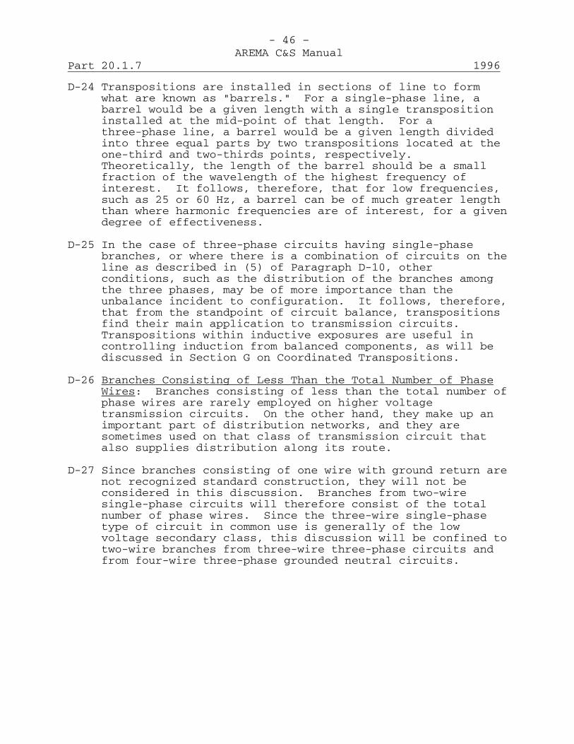
- 46 –AREMA C&S Manual
Part 20.1.7 1996
D-24 Transpositions are installed in sections of line to formwhat are known as "barrels." For a single-phase line, abarrel would be a given length with a single transpositioninstalled at the mid-point of that length. For athree-phase line, a barrel would be a given length dividedinto three equal parts by two transpositions located at theone-third and two-thirds points, respectively.Theoretically, the length of the barrel should be a smallfraction of the wavelength of the highest frequency ofinterest. It follows, therefore, that for low frequencies,such as 25 or 60 Hz, a barrel can be of much greater lengththan where harmonic frequencies are of interest, for a givendegree of effectiveness.
D-25 In the case of three-phase circuits having single-phasebranches, or where there is a combination of circuits on theline as described in (5) of Paragraph D-10, otherconditions, such as the distribution of the branches amongthe three phases, may be of more importance than theunbalance incident to configuration. It follows, therefore,that from the standpoint of circuit balance, transpositionsfind their main application to transmission circuits.Transpositions within inductive exposures are useful incontrolling induction from balanced components, as will bediscussed in Section G on Coordinated Transpositions.
D-26 Branches Consisting of Less Than the Total Number of PhaseWires: Branches consisting of less than the total number ofphase wires are rarely employed on higher voltagetransmission circuits. On the other hand, they make up animportant part of distribution networks, and they aresometimes used on that class of transmission circuit thatalso supplies distribution along its route.
D-27 Since branches consisting of one wire with ground return arenot recognized standard construction, they will not beconsidered in this discussion. Branches from two-wiresingle-phase circuits will therefore consist of the totalnumber of phase wires. Since the three-wire single-phasetype of circuit in common use is generally of the lowvoltage secondary class, this discussion will be confined totwo-wire branches from three-wire three-phase circuits andfrom four-wire three-phase grounded neutral circuits.
- 47 –AREMA C&S Manual
1996 Part 20.1.7
D-28 In discussing branches from three-phase circuits, it will beconvenient to consider the matter from three viewpoints:namely:1. The balance of the branch.2. The balance of the three-phase circuit.3. The net result when the three-phase circuit is
energized in a balanced manner.
On extensive systems or long branches, the matter ofpropagation resulting in resonance effects at harmonicfrequencies becomes involved. In the following discussionParagraphs D-29 to D-34, inclusive, consider first thesituation where such effects do not arise. A discussion ofthese effects is given in Paragraph D-37.
D-29 A two-wire branch from a three-wire three-phase circuit,even if approximately balanced of itself, will experience aresidual voltage when energized due to the fact that thevector sum of the voltages to ground on the two wires is notzero. If the loads on the branch are connected between thetwo wires only, the load current in the branch will bebalanced. Where the branch is short, charging current maynot be of importance. Where, however, the branch is ofconsiderable length, residual charging current, due to theaction of the residual voltage on the capacitance to ground,may have an important effect on exposures to the branchparticularly if they are located near the supply end of thebranch.
D-30 On the three-phase circuit the effect of the branch is tounbalance the circuit since, in effect, it adds admittanceto ground to two of the phase wires without a correspondingaddition to the third. When the circuit is energized in abalanced manner, two conditions have to be considered:first, if the neutral is not grounded the branch will causethe residual voltage normally on the three-phase line to beincreased, but the total residual voltage on the three-phaseline will not be as great as the residual voltage on thebranch. Second, if the neutral is grounded the branch willaffect the residual voltage of the three-phase circuit butto a smaller extent than with the isolated neutral, and willincrease the ground return charging current.
D-31 Two-wire branches from four-wire three-phase circuits mayconsist of branches from two-phase wires or from phase and

- 48 –AREMA C&S Manual
Part 20.1.7 1996
neutral, the latter being referred to hereafter asphase-neutral branches. Branches form two phase-wires willhave the same effect in this case as in the case of thethree-wire three-phase circuits discussed in ParagraphsD-28, D-29 and D-30. In considering phase-neutral branchestwo conditions arise; first where the neutral is grounded atthe supply end only; and second, where the neutral isgrounded at the supply end and at a number of points alongthe line. These two conditions will be referred to asuni-grounded and multi-grounded neutral, respectively.
D-32 A phase-neutral branch from a uni-grounded neutral four-wirethree-phase circuit may, of course, he approximatelybalanced if considered apart from the three-phase circuit.However, when connected, one wire of the branch will begrounded and the branch will therefore be unbalanced. Whenenergized, the full voltage on the branch will appear asresidual voltage. The load current on the branch will bebalanced, but there will exist a residual charging currenthaving earth return which may have an important effect onexposures to the branch particularly near the supply end.
D-33 A phase-neutral branch from a multi-grounded neutralfour-wire three-phase circuit is unbalanced since one wireis grounded at various points along its length. Whenenergized, the full voltage will appear as residual voltage.A substantial part of the load current, and of thetransformer exciting current, gets into the earth throughthe ground connections. On the other hand, charging currentthat flows through the capacitance between the phase wireand ground is partly pulled back (through magnetic inductiveaction) from the earth into the neutral wire. These twoopposing effects have a net result that may be in eitherdirection at noise frequencies; that is, having multiplegrounds, instead of no grounds, along the branch, may resultin either a smaller or a larger inductive influence,depending on whether the more important factor is chargingcurrent (as in long, lightly-loaded lines at the highervoltages), or load current plus transformer exciting current(shorter, more heavily-loaded, lower voltage lines). Thewave-shape of the impressed voltage is also an importantfactor in these considerations. At the fundamental andlower harmonic frequencies the inductive influence of amulti-grounded

- 49 –AREMA C&S Manual
1996 Part 20.1.7
neutral branch is considerably greater than that of onehaving no grounds.
D-34 Regarding the effect of a phase-neutral branch on thethree-phase circuit, the latter circuit will be unbalancedwhether the neutral is uni-grounded or multi-grounded, sincethe effect is that of adding admittance to ground to onephase-wire without similar additions to the other twophase-wires. When the circuit is energized, the residualvoltage of the three-phase circuit will not be substantiallychanged by connecting the branch to it whether the neutralis uni-grounded or multigrounded, and the ground returnresidual current will be increased in either case.
D-35 If a three-phase four-wire circuit has a number of similarphase-neutral branches, the Z will be approximately balanced(aside from propagation effects) if the mileage of branchlines is approximately the same for all phases. This doesnot necessarily mean, however, that the charging currentwill be even approximately balanced at all points of thethree-phase circuit. Thus, for example, if the branchesfrom one phase are all taken off in a single stretch ofline, and no other branches are connected within this partof the line nor between it and the point of supply, it isobvious that the charging current may be very substantiallyoff balance at the end of this part of the circuit that isfarthest from the point of supply. To avoid this kind ofsituation, the mileage of branch lines should evidently bedisturbed equally among the phases, not merely on anover-all basis, but also within suitably short sections ofthe main circuit. To do this may be difficult if there area few scattered long branches and many short ones. In suchcases, the long branches, or some of them, may be connectedto the main circuit through two-winding transformers. Ifsuch transformers are connected to two phase-wires of themain circuit, the branch will not cause capacitanceunbalance to ground in the main circuit, regardless of thetype of grounding (uni- or multi-) of the neutral wire, andregardless also of whether the branch itself is grounded onone side. But if the transformer is connected between aphase-wire and the neutral wire, the use of it will notprevent the branch from unbalancing the main-circuitcapacitance to ground, nor (if the main-circuit has a multi-grounded neutral) the appearance
- 50 –AREMA C&S Manual
Part 20.1.7 1996
of ground-return residual current in the main circuit, dueto branch capacitance and loads.
D-36 It should be noted that the method of obtaining balance asdiscussed in Paragraph D-35 may have no relation to loadbalance among the phases and that the best distribution ofbranches from the standpoint of load balance may be far fromthe best from the standpoint of circuit balance. Inconsidering balance, therefore, it is necessary to determinewhich type of balance is important and be guidedaccordingly. At fundamental frequencies, load balance is ofprime importance.
D-37 Where branches of considerable length are involved, or wherethe branches are associated with an extensive three-phaseline, the capacitances and inductances which go to make upthe self and mutual impedance and admittances to ground maybe in such a combination as to approach a condition ofresonance for certain harmonic frequencies which may bepresent in the impressed voltage or which may be produced byloads. When this condition obtains, induction due to thefrequency or frequencies concerned will be accentuatedthroughout the length of the branch. Furthermore, thecondition of resonance on the branch may materially affectthe inductive influence of the three-phase portions of thesupply line as well as that of other single-phase branchesfed from the latter.
D-38 In considering the application to practical problems of theforegoing discussion, three types of situations involvingdistribution circuits may arise; namely, (1) urbandistribution, (2) suburban distribution, and (3) ruraldistribution.
D-39 In urban distribution, the supply and communication circuitsquite commonly occupy joint poles. The communicationcircuits are generally in cable, the sheath of which, whengrounded, provides an effective shield against electricinduction. In such cases, therefore, magnetic inductionfrom the power system currents is practically alwayscontrolling. Since the feeders are usually short andoperate at 6600 volts or below, charging currents may beexpected to be less important than harmonic components ofthe load and transformer exciting currents. On urbandistribution systems, therefore, equal distribution of loadand connected kva of transformers
- 51 –AREMA C&S Manual
1996 Part 20.1.7
between the various phases is of greater significance thanequal capacitances of the various phase wires to ground.
D-40 In suburban areas, the communication circuits may be acombination of cable and open wire and may be subject toeither electric or magnetic induction or both. In suchcases, therefore, particularly where the power circuits arelong, capacitance balance as well as load balance on thedistribution circuits must receive consideration.
D-41 In rural areas the supply circuits may be long and may belargely made up of single-phase branches or circuits, andthe loads are generally relatively light. In such cases themore important factors from the noise induction standpointare ground return charging current, the distribution of thebranches among the three phases of the feeder circuit, waveshape and in some cases residual voltage.
D-42 At fundamental frequency, load balance rather thancapacitance balance is controlling, in nearly all cases.Due to the normal variation of loads with time, as well asthe fluid nature of distribution lines, the control ofinfluence by load balance of three-phase, four-wire lineshas not been especially successful in practice.
D-43 In exposures to single-phase multi-grounded neutral lines,no possibility of load balance exists. For the sizes ofneutral wires commonly used, about 75% of the load currentat fundamental frequency returns through the ground.
Balance of Communication CircuitsD-44 A metallic communication circuit is balanced if its two
sides have equal self-impedances and admittances to ground,and equal mutual impedances and admittances to neighboringconductors, in each elementary section of its length. Thisdefinition applies both to metallic circuits of twoconductors and to phantom circuits. In the latter case, thewires composing the side circuits from which the phantom isderived are considered as being in parallel, and are treatedas if they were single conductors.
D-45 This definition is in substantially the same terms as thedefinition given in Paragraph D-2 of balance in the case ofa supply circuit, and most of the discussion given inconnection with that definition applies directly (in most
- 52 –AREMA C&S Manual
Part 20.1.7 1996
cases with suitable and obvious changes in wording) to this.Thus longitudinal uniformity is not necessary to acondition of balance in a communication circuit, it is onlynecessary that corresponding electrical constants of the twosides of the circuit should be equal in each elementarysection. An elementary section, from a practicalstandpoint, can be taken as a transposition section, and iftaken in the vicinity of a branch on one side of a phantom,it must include the branch connections. The condition ofbalance of a communication circuit does not depend upon itsmode of energization, but depends only on the self andmutual characteristics of the conductors of the circuit andneighboring conductors. In an exposure, a metalliccommunication circuit may be energized longitudinally bymagnetic induction from a supply circuit, and from wires toground by electric induction; but no metallic circuitvoltages or currents will result from these components ofinduction unless the circuit, or equipment connected to it,is unbalanced. As it is impossible entirely to preventunbalances in communication circuits or equipment, metalliccircuit effects always follow from longitudinal induction orinduction to ground. Practically, it is simply a questionof the magnitudes of these effects.
D-46 Line Unbalances: Unbalances of communication circuits areof two general types. The first may be called self-unbalances, involving only the conductors of the circuit andground, and the second, mutual unbalances involving otherconductors. Thus, a self-unbalance would exist even thoughall other conductors except those of the circuit in questionwere moved beyond the field of influence. In practice bothself unbalances and mutual unbalances may have anunfavorable influence from an inductive standpoint. Theresulting current or voltage in a circuit depends on boththe self and mutual unbalances, and upon the modes ofenergization and terminal impedances of the circuit inquestion and neighboring conductors.
D-47 Mutual Unbalances: In practice, none of the circuits onmulti-wire lines are inherently balanced in respect to theirmutual relations to other conductors. A close approximationto such balance is obtained, however, by means oftranspositions whereby the unbalances existing in onesection are neutralized by those in a nearby section ofline. Thus transposition errors are the main source of

- 53 –AREMA C&S Manual
1996 Part 20.1.7
mutual unbalances. In a poorly maintained line, leakage maybe a factor.
D-48 The mutual unbalances that remain in a well-transposed lineare largely of the nature of shunt unbalances, i.e., theyare equivalent to admittances connected from a wire of onecircuit to a wire of another circuit. In other words, if awell-transposed pair is energized to ground, both currentsand charges are produced in other wires. The currents inthe well-transposed pair itself are unequal, due to theother wires, but largely because of their charges ratherthan because of their currents.
D-49 Self-Unbalances: Self-unbalances may be divided into thegeneral classifications; namely, series impedance unbalancesand shunt admittance unbalances.
D-50 A series impedance unbalance is a difference, usually local,between the series impedances of the two conductor composingthe circuit. Such an unbalance may be caused, for example,by a high resistance joint in one of the conductors. Ifsuch a joint exists, the longitudinal currents in theconductors due to induced voltages encounter unequalimpedance with a resulting difference in voltage drop on thetwo conductors. This difference in voltage drop causes avoltage acting around the circuit, which tends to causenoise-metallic. The effect of a given series unbalancedepends, of course, on the longitudinal current through it,which in turn depends on the voltage or noise to ground andthe admittance to ground of the circuit on either side ofthe unbalance.
D-51 Shunt admittance unbalances are generally due either tounbalanced capacitances to ground or to unbalanced leakancesto ground of the two wires. The effect of an admittanceunbalance is to cause more current to flow to ground fromone side of the circuit than from the other. Part of thisexcess current is drawn from the other side of the circuit,thus flowing through the terminal equipment and therebycausing noise-metallic.
D-52 Some of the most common sources of self-unbalances are:1. Series impedance unbalances (line):
a. Defective splices in line conductors.b. Contact resistance in test connectors, binding
posts and fuses.

- 54 –AREMA C&S Manual
Part 20.1.7 1996
c. Broken line conductors in tie wires.
2. Shunt admittance unbalances (line):a. Defective insulators.b. Contact of line wires with trees, vines,
crossarms, guy wires, foreign wires or with wiresfalling across the line.
c. Leakage at protectors.d. Capacitance or insulation unbalance in cables.e. Defective insulation on bridle wires.f. Capacitance unbalance due to transposition errors
or irregularities.
D-53 Other precautions that should be observed in connection withphantom circuits to avoid unbalancing them are:1. When terminating one side circuit at an intermediate
point, balancing resistance or other compensatingapparatus should be inserted in the through side of aphantom group at a point where the other side circuitis terminated.
2. When one side circuit of a phantom is looped into anoffice, the other side circuit also should be looped into avoid capacity and series unbalances in the phantom.
3. When a branch is connected to one side circuit only ofa phantom group, the connection should be made to theside circuit through a repeating coil, or a branchhaving the same characteristics should be connected tothe other side circuit. If the branch is terminated ina switchboard or at other point where it may beconnected to other circuits, a repeating coil is alwaysadvisable.
Equipment UnbalancesD-54 Circuit unbalances may be caused by office or station
equipment and associated wiring if the equipment is notproperly designed and constructed for the service inquestion or is not properly maintained. Equipmentunbalances have the same general effect as line unbalances.They are especially important on phantom and compositecircuits.
D-55 Office Unbalances: Some of the more common sources ofoffice equipment and wiring unbalances are:
- 55 –AREMA C&S Manual
1996 Part 20.1.7
1. Composite set unbalances:a. Unbalance between the elements of composite sets
in two sides of a phantom group.
b. Unbalance between various parts of a compositeset:--- Series condensers.--- coils in telegraph branches.--- Condensers in telegraph branches.--- Coils in grounded branches.
2. Loose connections due to rosin joints or poorlysoldered joints.
3. Drops of solder, wire clippings, etc., falling onterminals causing crosses, grounds or short-circuitedapparatus.
4. Poor connections at relay contacts in talking circuits.5. Relay contacts normally open when talking, failing to
open.6. Variable resistance contacts at heat coils.
D-56 Station Unbalances: Telephone station lines are subject toself and admittance unbalances as described in ParagraphD-52. Telephone station equipment is always subject tounbalances, the more common sources of which are:1. Leakage at protectors.2. Unequal resistance at fuses, station terminals and
switches.3. Defective cords.4. Ground return ringing.
In situations where ground return ringing is employed, theunbalance can often be reduced by the use of either a ringerhaving high impedance at harmonic frequencies or by the useof a relay at the station which will connect the ringer toground only during the ringing period.
E-Transpositions
GeneralE-1 If the two sides of a metallic communication circuit were
infinitely close together and thus equally exposed to aparalleling supply circuit, there would be no voltageinduced directly in the metallic communication circuit.Similarly, if the supply conductors were infinitely closetogether and thus equidistant from the communication
- 56 –AREMA C&S Manual
Part 20.1.7 1996
circuit, there would be no longitudinal circuit induction inthe communication circuit from balanced components ofcurrent and voltage in the supply circuit. These idealconditions cannot, of course, be realized in practice.However, by means of transpositions in the supply andcommunication circuits, the direct-metallic induction andthe longitudinal-circuit induction from balanced componentsoccurring within adjoining sections of the communicationcircuit may be neutralized to a degree and an approximationto the ideal arrangement may thus be effected.
E-2 An open wire communication circuit is said to be transposedwhen the two sides of the circuit reverse their respectivepin positions on the line according to a definite plan. Ametallic circuit voltage (voltage between the two sides ofthe circuit) induced from an external source in a section ofthe circuit on one side of a transposition tends to beneutralized by the corresponding voltage on the other sideof the transposition, since the voltage in the secondsection is reversed with respect to that in the first by thetransposition. The interchange of pin positions by theconductors of a communication circuit at the transposition(the exposure conditions at the point of transposition beingotherwise uniform) may be said to cause a phase change of180 deg. in the metallic circuit induction in thatparticular communication circuit. Communication circuittranspositions have no effect on longitudinal-circuitinduction because this type of induction takes place in thecircuit composed of the communication wires in parallel asone side and the earth as the other.
E-3 Supply circuit transpositions, on the other hand, may beused effectively to reduce longitudinal-circuit inductionfrom balanced components of current and voltage on thesupply circuit.
E-4 Transpositions in a supply circuit do not reduce theinduction from residual components, which act in a circuitof which the earth forms one side, except as they may do soindirectly by reducing the residuals themselves.
E-5 In the case of ground-return communication circuits whereonly longitudinal-circuit induction is encountered,transpositions are practicable only in the supply circuit.
- 57 –AREMA C&S Manual
1996 Part 20.1.7
E-6 The effect of transpositions in interchanging phaseconductor positions is to establish for the over-all circuita condition of equal induction between each of the severalsupply conductors and the disturbed circuit.
E-7 A section of supply circuit of uniform configuration withinwhich the transpositions are so arranged that each conductoroccupies each of the conductor positions for an equivalentlength is commonly known as a "barrel."
E-8 The neutralizing effect of supply circuit transpositions onlongitudinal-circuit induction results from the change inphase of the electric and magnetic fields of the balancedcomponents of voltages and currents, respectively,accompanying a change in the relative positions of thesupply wires.
E-9 In a single-phase system where the currents in the twosupply wires are equal in magnitude and opposite indirection, that is, 180 deg. out of phase, a transpositionin the supply circuit changes the phase of the induction by180 deg. Therefore, within a uniform parallel, one suchtransposition will neutralize the longitudinal-circuitinduction from balanced components into the communicationcircuit, if located at the mid-point of the exposure.
E-10 Similarly, in a three-phase system, where the currents inthe phase wires are 120 deg. apart, a transposition in thesupply circuit changes the phase of the induction by 120deg. Two three-wire transpositions of identical type,dividing a uniform parallel of a three-phase line into threeequal parts, will neutralize the longitudinal-circuitinduction on the communication circuit resulting frombalanced components. The application of this method,however, is attended with difficulties in practical casesbecause of the irregular exposures usually encountered. Insuch cases, the transpositions are located, not at thegeographical third points, but at the points correspondingto thirds of the induced potential. This is the normalmethod of forming a transposition barrel.
E-11 In specific exposures, these theoretical transpositionlocations will, often times, not fall opposite neutralpoints in the communication transposition system. In thesecases, the question as to whether it is preferable to movethe supply line transposition, and thus avoid introducing
- 58 –AREMA C&S Manual
Part 20.1.7 1996
metallic circuit induction, at the expense of thelongitudinal circuit induction, must be answered. In otherwords, the relative importance of the direct and indirectmetallic circuit induction, as modified by supply circuittranspositions, as well as the effect of the un-neutralizedlongitudinal induction on grounded circuits, must beevaluated. Where the longitudinal induction predominates,it may sometimes be preferable to re-transpose themetallic-communication circuits to coordinate with thetheoretical locations of the supply line transpositions.
E-12 The application of transpositions to multi-grounded-neutralsupply circuits is usually not warranted. On such circuitsthe ground return components usually predominate; therefore,reduction of the balanced components by transpositions is oflittle benefit.
E-13 The common functions of supply and communication circuittranspositions may be summarized as follows:1. Supply circuit transpositions within exposures tend to
reduce longitudinal-circuit induction due to balancedcomponents. They may tend to reduce induction due toresidual components if they reduce the magnitude of theresiduals themselves; they do not affect the inductionfrom given amounts of residuals. Furthermore, they mayeither increase or decrease the direct metallic circuitinduction.
2. Supply circuit transpositions outside of exposures haveno effect on either metallic circuit orlongitudinal-circuit induction due to balancedcomponents. They may tend to reduce induction due toresidual components if they reduce the magnitude of theresiduals themselves.
3. Supply circuit transpositions within exposures, wherethe supply line carries one or more overhead groundwires, tend to reduce the effect of induced currentflowing in these wires. This is helpful in situationswhere normal induction from fundamental frequencycurrents is concerned.
4. Where the supply line carries a drained telephonecircuit, the fundamental frequency induction frominduced current flowing in this circuit may be reduced
- 59 –AREMA C&S Manual
1996 Part 20.1.7
by supply line transpositions designed to providebalance between drainage points.
5. Supply circuit transpositions are of little benefit formulti-grounded-neutral systems.
6. Communication circuit transpositions tend to reducecross-induction between the various circuits on thecommunication line.
7. Communication circuit transpositions within inductiveexposures tend to neutralize metallic circuit inductionfrom both the balanced and residual components of thesupply system. They have no effect onlongitudinal-circuit induction.
8. Communication circuit transpositions outside ofexposures have no effect on direct metallic circuitinduction. They do, however, tend to reduce theindirect metallic circuit induction (from either thebalanced or residual components of the supply system),if they reduce unbalances that might be acted upon bythe longitudinal-circuit induction.
Application of TranspositionsE-14 Supply Circuit Transpositions: The considerations which
determine the need and application of transpositions insupply circuits in the case of normal low frequencyinduction may differ widely from those governing when noisefrequency induction predominates. Low frequency inductioninvolves the fundamental frequency and the lower range ofharmonic frequencies while noise frequency inductioninvolves the harmonic frequencies in the noise frequencyrange. Where the TIF of the supply system is lowtranspositions in the supply circuit may not be necessaryfrom the standpoint of noise frequency induction whereasthey may be necessary to reduce induction at the fundamentalfrequency. On the other hand, in situations where noisefrequency induction is the only problem, the control of thesupply system wave shape may provide a more economical meansof reducing the supply system influence than the use oftranspositions.
Supply Circuit Transpositions for-Low Frequency Induction(This discussion on supply circuit transpositions for lowfrequency induction refers principally to three-phase

- 60 –AREMA C&S Manual
Part 20.1.7 1996
systems. However, the underlying theory applies equallywell to single-phase circuits.)
E-15 When a preliminary study of a given situation has indicatedthe possible need of supply circuit transpositions, theorder of procedure might be as follows:
1. The obtaining of complete information about thephysical characteristics of the exposure and thepreparation of an exposure chart showing the relationof the communication line to the supply circuitsinvolved in the exposure.
2. The obtaining of complete information regarding theoperating characteristics of the supply system,including maximum probable load, transformerconnections, location of neutral ground connections,type of relaying, etc.
3. The determination of the induced voltage and its effecton service.
4. If transpositions in the supply line seem necessary, anestimate should be made of the minimum number oftranspositions required.
5. The determination of the most desirable locations forthe transpositions, taking into account the minimizingof the effects on both grounded and metalliccommunication circuits.
E-16 Careful consideration must be given to the number, locationand relative importance of discontinuities within theexposure. A discontinuity as herein used is any point atwhich an abrupt change occurs in the magnitude or phase ofthe supply line voltages or currents, or in the resultinginduced voltage. Particular examples are:1. Generating stations.2. Switching or transformer stations.3. Substations or load points.4. Abrupt changes in separation.5. Changes in configuration of the supply line.6. Crossovers.

- 61 –AREMA C&S Manual
1996 Part 20.1.7
E-17 Transpositions, because of their application tocoordination, are not considered as discontinuities,although technically included in the term.
E-18 The lengths of supply line transposition barrels are largelydetermined by the exposure discontinuities. Attenuation andphase change effects, which are of importance at noisefrequencies, are less important in the usual type of lowfrequency problem.
E-19 Working, then, with sections between discontinuities, thelongitudinal-circuit-induced voltage is determined, asexplained below, for the entire exposure. The amount ofthis voltage and its effect on the operation of the variouscommunication circuits involved are the basis for anestimate of the desired number of supply linetranspositions.
E-20 It is then necessary to select the balance or neutral pointsfor the transposition system to be used to obtain the bestneutralization of induction consistent with the minimumnumber of barrels. It is desirable that these points occurat discontinuities. However, to locate such points at alldiscontinuities is often impracticable so that carefulconsideration should be given to the relative importance ofdiscontinuities to determine if the minor ones cannot bedisregarded. For example, where the load taken off at anintermediate substation is a small proportion of the totaltransmitted load, this discontinuity may be ignored.
E-21 One or more barrels of transpositions are located betweensuccessive balance points when the longitudinal-circuitinduction is sufficient to warrant their use.
E-22 The usual procedure in designing a barrel of transpositionsis to endeavor to locate the two transpositions at pointscorresponding to 1/3 and 2/3 of the total induction betweenbalance points. As explained previously, thelongitudinal-circuit induction in the three sections shouldthen be 120 deg. apart and thus should neutralize. However,in locating the supply circuit transpositions, considerationmust be given to the effect on direct metallic circuitinduction.
- 62 –AREMA C&S Manual
Part 20.1.7 1996
E-23 In designing transposition systems for supply lines whichcarry overhead ground wires, consideration must be given notonly to the balanced current effects directly but also tothe effect of the residual current flowing in the groundwires as a result of induction from the currents in thephase conductors. The relative magnitudes of these twocomponents of induction will determine what source should begiven greater weight in the transposition design.Paragraphs E-36 to E-40, inclusive, discuss the method ofestimating the effect of ground wires.
E-24 Balanced Current Induction: In computing the induction forsections of uniform exposure, the coefficient of inductionat the separation concerned is multiplied by the length ofthe paralleling section. The coefficient of induction maybe determined from the curves given in Section D in terms ofvolts induced per ampere or per 100 amp. in the supplycircuit per unit of length of the exposure. Slopingexposures may be divided into short elements, in which theseparation at the two ends does not differ by more than 10%,and induction in each short element determined bymultiplying the average coefficient by the length of theelement. The average coefficient for each short element isobtained by taking the average of the coefficients for theseparations at the two ends of the element. Since thisaverage point is located on the chord of the coefficientcurve rather than on the curve itself, it is necessary touse short elements, that is, elements in which the change inseparation is not great in order to avoid introducing toolarge an error. At close separations where the coefficientof induction is large, and at separations where the slope ofthe coefficient curve is changing rapidly*, frequentsubdivision of the sloping exposure is especially important.However, when the length of sloping exposure is so shortthat the induction from it is small compared to the total,fewer subdivisions may be used. A somewhat similar methodof treating sloping exposures that, however, uses theaverage separation for the small elements rather than theaverage of the coefficients, is described in Section D.
* The slope of the coefficient curves for a vertically configured supplyline changes more rapidly at certain separations than the coefficientcurves for any other configuration.
- 63 –AREMA C&S Manual
1996 Part 20.1.7
E-25 For either method, the induction (average coefficient timeslength) for each of the small sections is added cumulativelyand the transpositions (for each barrel) are located atpoints equal to 1/3 and 2/3 of the total induction; i.e.,the actual transposition points are found by interpolationat the 1/3 and 2/3 points of the cumulative column.
E-26 The layout should be inspected to ascertain the relation ofthe transpositions to the neutral points of thecommunication circuit transposition system. In general, ifthe supply circuit transposition locations were to bealtered to fit these neutral points, there would usually besome un-neutralized longitudinal induction. Considerationmust be given to the effect of this on both direct andindirect metallic circuit induction, and on groundedtelegraph circuits. A decision is then in order as to thedesirability of the more exact longitudinal balance obtainedby using the theoretical transposition locations, and thepossible necessity of re-transposing or installing wholeline transpositions in metallic circuits within theexposure.
E-27 Where more than one barrel of transpositions is to be used,a similar procedure is followed between the next pair ofbalance points.
E-28 Design of Barrels in Pairs: Where the length of barrel isnot limited by discontinuities, and where theoreticalconsideration shows the desirability of installing twoconsecutive barrels in a particular exposure, it isdesirable to design the two barrels to be exactly alike, bylocating the transposition points at the 1/6, 1/3, 2/3 and5/6 points of the total inductive length. It is frequentlymore economical to install initial transpositions at the 1/3and 2/3 points. If later it develops that further reductionis necessary, a second barrel can be obtained by addingtranspositions at the 1/6 and 5/6 points.
E-29 Transpositions at Ends of Barrels: In general,transpositions should not be used at the ends of completetransposition barrels, since this would increase theunbalance due to phase change, and also the cost oftransposing. Where it is necessary to have particular phaserelations at given points, this condition can often
- 64 –AREMA C&S Manual
Part 20.1.7 1996
be met by rolling certain barrels in opposite directionsinstead of transposing at the junction points.
E-30 Crossovers: The direct balanced current induction from asupply line of horizontal configuration is changed in phaseby 180 deg. at points of crossing over a communication line.Sometimes such a crossover, therefore, may be usefullyemployed in lieu of transpositions, when the exposuredimensions are similar in the two directions from thecrossover. This method is of no benefit for a supply linehaving vertical or unsymmetrical configuration, nor willthere be any reduction by use of this method in theinduction from residual current flowing in the overheadground wire.
E-31 Use of One Three-Phase Transposition: Where a barrel oftranspositions cannot be economically justified but wheresome relief from inductive effects is required, athree-phase transposition, located at the inductive centerof the exposure, will reduce the longitudinal-circuitinduction by approximately 50 percent.
E-32 Balance to More Than One Communication Line: Where thereare two communication lines involved in the same exposure,it is not usually possible to provide equal coordination toboth. In such cases, the more important communication line,or the one more closely exposed, should be given greaterconsideration in designing the transposition scheme. If, asis the usual case, the balance to the other line isimperfect, it may often be improved by rolling certainbarrels in the opposite direction, and by insertingadditional transpositions at the balance points.
E-33 In general, a diagram, similar to Figure 16, should beprepared, showing the theoretical transposition points, andthe method of rolling the individual transpositions. This isespecially important when reversed barrels are to be used.
E-34 Transpositions to Reduce Residuals in Ground Wires* PhaseConductors* etc.: Supply line transpositions do notmitigate inductive effects due to residual currentsdirectly, but such transpositions may reduce the inductionindirectly as described below.
- 65 –AREMA C&S Manual
1996 Part 20.1.7
E-35 Ground Wire Induction: Overhead ground wires on a supplyline may be an important source of low frequency induction.It is evident that if the phase wires are not transposedwith respect to these wires, a voltage to ground will beinduced along them by the balanced phase currents, and aground return current will flow which may be of considerablemagnitude particularly where high conductivity ground wiresare used.
E-36 The resulting ground wire residual current induction onparalleling communication circuits may be largely reduced bysuitable transpositions in the phase conductors. Thesetranspositions must be located with due regard to thevarying separation between the supply and communicationlines in the usual manner. Since the ground wire isnormally grounded at frequent intervals, the transpositionbarrels, while they will change the phase of the inductioninto the ground wire in each third of the barrel by 120deg., will not reduce the ground wire current, since thecurrents in each section will still flow to ground throughthe ground connections. However (if the earth resistivityis constant throughout the barrel and) if the transpositionsare so located that the coupling to residual currents isequal in each third of the barrel, there will be no residualcurrent induction on the communication circuits, since theinductive effects of the current flowing in the ground wirein the individual barrel thirds will be equal and 120 deg.apart, and hence will tend to cancel. In some situations,this ideal condition may not be fully realized because ofend effects, and for this reason it is sometimes advisablein severe cases to establish low impedance grounds (5 ohmsor less) on the ground wire at the ends of the exposure andat transposition locations.
E-37 The calculation of ground wire induction is performed byfirst computing the current in the ground wires per unit ofbalanced current. The coupling to the communication line isdetermined in the same manner as described in Paragraph E-24for balanced current, except that the residual currentcoupling curve is used. Interpolation for transpositionpoints is likewise done in the same way. Because of thedifferent shape of the coupling curves for balanced andresidual current induction, the transposition points (exceptfor uniform exposures) may not be at the same locations forthe two types of induction.
- 66 –AREMA C&S Manual
Part 20.1.7 1996
E-38 Transpositions to balance to the ground wire are needed onlywithin the limits of the exposure, but it is important toremember that since a residual current is being considered,as far as fundamental frequency induction is concerned, itseffects may be appreciable at separations of a mile or more,especially in regions of high earth resistivity.
E-39 It may be assumed that the ground wire current flows toearth at every point where this wire is grounded (such as attowers), but since an equal current flows up the tower dueto the induced potential in the next span, the net result isthat of a uniform current flowing throughout the length ofthe ground wire, with current flowing to ground only attowers near where the ground wire is interrupted, wheretranspositions are installed, and at the ends of the line.
E-40 Balance to Ground: Residual currents are usually present inthe phase wires of an un-transposed supply line due to theunbalanced series impedance and admittance to ground of theseveral phase conductors. The magnitude of the residualcurrent is determined by the impressed voltage, loadcurrent, conductor configuration, length of supply line,location of grounded transformer banks, and other factors.This type of residual may be reduced by transposing thesupply line throughout its length, thus equalizing theseries impedances, and capacitances to ground of the phaseconductors.
E-41 Load and Single Phase-Extension Unbalance: Where theresidual current is due to unbalanced load currents, as inthree-phase four-wire multi-grounded neutral distributioncircuits or to the unequal lengths of single phaseextensions connected to the various phases, transpositionsare of little benefit.
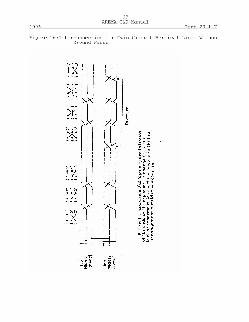
- 67 –AREMA C&S Manual
1996 Part 20.1.7
Figure 16:Interconnection for Twin Circuit Vertical Lines WithoutGround Wires.
- 68 –AREMA C&S Manual
Part 20.1.7 1996
E-42 Composite systems: Since, except in uniform exposures, itis impossible to design a system of supply linetranspositions which will be fully effective in reducingboth the induction from the balanced load currents and fromthe current flowing in other parallel wires, such as groundand telephone wires, the relative interfering effect of eachof these must be determined for each specific exposure, andthe transposition scheme laid out giving due considerationto their relative weights. In an existing exposure, it issometimes possible to determine the relative importance ofthe various sources of induction by actual tests; but inproposed cases, this must be done by calculations. Thetransposition scheme should be designed to provide thegreatest relief from the induction as a whole, consistentwith cost and practicability.
E-43 Combined systems of supply circuit transpositions may beused. A common scheme is to lay out transpositions withinthe exposure against balanced current or ground wireinduction, and to install additional transpositions outsidethe exposure to reduce residuals. Transpositions maysometimes be necessary in one or both of two parallelingpower supply circuits in order to reduce their combinedeffect, including secondary induction, on a parallelingcommunication circuit. While the general principles givenin this section will apply, such cases usually requirespecial consideration.
E-44 Interconnection of Phases of Twin Circuit Lines: The phaseconductors of twin circuit supply lines may generally beinterconnected to produce a partial neutralization ofparticular inductive effects from the two circuits. Ageneral recommendation as to the most advantageous method ineach case is not possible, as numerous factors govern thetype to use in any particular case. Considering only theinductive effect of the twin circuit due to balancedcurrents, Figure 17 shows the relative merits of differentmethods of interconnection for a few configuration types atspecific separations. The ratios given as IE in the drawingare approximate and will vary with conductor spacing andline separations, but the merits of the various methods ofinterconnection are, in general, as indicated. If groundwires or a telephone circuit are present on the supply line,a special study is necessary.
- 69 –AREMA C&S Manual
1996 Part 20.1.7
E-45 Methods of Transposition: When transposing twin circuitlines, both circuits should be transposed at the same point,except as explained in Paragraph E-47.
E-46 Transpositions in the two circuits should be rotated in sucha manner that the chosen interconnection is maintained ineach part of the transposition barrels. Figure 18 indicatesthe direction of rotation to be employed with variousmethods of interconnection for vertical configuration.
E-47 Combined Systems: The interconnection which gives the leastinduction from balanced currents, Figure 17, in general, isnot the one which gives the best balance to ground. Forthis reason, it may be desirable to transpose one of thecircuits on a twin circuit line at the balance points at theend of the exposure as shown on Figure 16 in order to changefrom the best configuration for balanced current inductionwithin the exposure to the best for balance to groundoutside the exposure.
E-48 Interconnection for Least Capacitance Unbalance: For twincircuit lines in vertical configuration* without groundwires, the interconnection giving least capacitanceunbalance is with the top conductors of each circuit at thesame phase, and the two bottom conductors diagonallyinterconnected, as shown on Figure 19. When ground wiresare used, the bottom conductors should be at the same phase,and the two top conductors diagonally interconnected. Fortwin circuits in triangular configuration without groundwires, the least capacitance unbalance results whensimilarly located conductors of each circuit are at the samephase. For other arrangements a special study is necessary.
Supply Circuit Transpositions to ReduceNoise Frequency Induction
E-49 Transpositions in supply circuits to reduce noise frequencyinduction must of necessity be located with due regard tothe communication circuit transpositions. The locations andarrangement of the transpositions in the two classes ofcircuit should be such as to form a coordinated layout.Such application is discussed in Paragraphs E-61 to E-76.
* Including those with center conductors displaced.
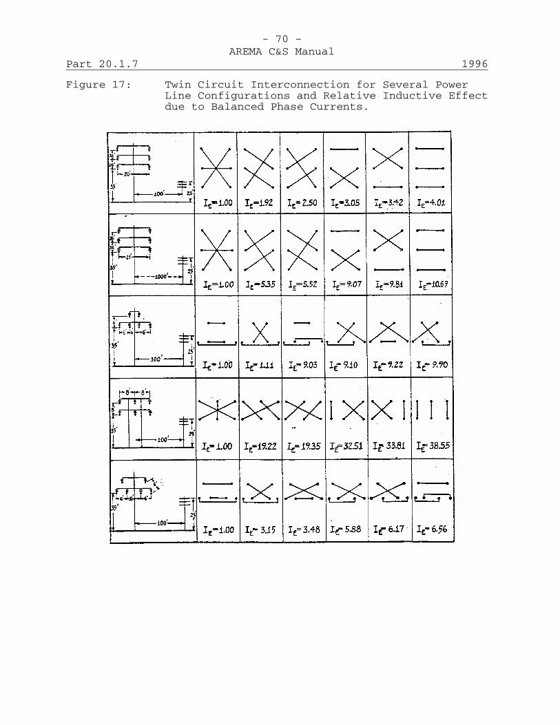
- 70 –AREMA C&S Manual
Part 20.1.7 1996
Figure 17: Twin Circuit Interconnection for Several PowerLine Configurations and Relative Inductive Effectdue to Balanced Phase Currents.

- 71 –AREMA C&S Manual
1996 Part 20.1.7
Figure 18:Direction of Rotation of Power Circuits with VariousTypes of Interconnection.
- 72 –AREMA C&S Manual
Part 20.1.7 1996
E-50 Communication Circuit Transpositions: Practically allmetallic open wire communication circuits are transposedthroughout their length. Even if no supply circuits arenear the communication line, transpositions are necessary tominimize the cross-induction between the various circuits onthe line. Transpositions installed solely for this purposein open wire communication circuits, however, do notnecessarily fit the discontinuities in exposures involvingneighboring supply circuits in such a way as to neutralizeeffectively induction from these supply circuits. Adecrease in the induction in a metallic communicationcircuit can usually be obtained in a given situation byarranging the transpositions with particular reference tothe discontinuities of the exposure. Thus communicationcircuit transpositions have two functions: to reduceinduction from other communication circuits on the same lineand to reduce the metallic circuit induction from the wiresof supply circuits located on the same line (joint use) oron a neighboring line.
E-51 The components of indirect metallic circuit induction causedby the action of longitudinal-circuit induction oncommunication circuit unbalances may arise either inside oroutside of exposed sections. Experience has indicated,however, that in many cases an exposed section is shortcompared to the total length of the communication line. Ithas therefore been convenient to refer to this effect asoccurring outside the exposed section and to contrast itwith the so-called direct induction into the metalliccircuit inside the exposed section.
E-52 The components arising outside the exposed section may bereduced by any means that reduce the longitudinal circuitinduction or the unbalances. The balance of thecommunication circuit depends to some extent on thetranspositions employed and in a particular case thecomponents of indirect metallic circuit induction might bereduced by changes in the arrangement of the communicationcircuit transpositions. However, the type of transpositionsection is not usually a controlling factor since there islittle practical difference in the effect of differenttransposition systems. For this reason and because of thelengths of the lines and the consequent number oftranspositions involved, it appears that the re-transposition of unexposed sections of communication line
- 73 –AREMA C&S Manual
1996 Part 20.1.7
is seldom a practical and economical measure for inductivecoordination.
E-53 Transposition Systems for Communication Lines: The designof a transposition scheme to take care of bothcross-induction and induction from supply circuits for anyconsiderable number of communication circuits on a line is acomplicated process. However, a definite system oftranspositions, known as the Exposed Line System, has beendeveloped for general application. Instructions coveringthe installation of the exposed line system are given inManual Part 1-D-9.
E-54 Exposed Line System: The Exposed Line System is designednot only to reduce cross talk but also to be suitable, whenproperly coordinated, for reducing the noise induction whichmight otherwise result from exposures with supply circuits.It consists of three types of sections, namely, standard,auxiliary, and unit designated by the letters E, L, and U,respectively.
E-55 Whole Line Transpositions: Whole line transposition unitswere developed in order to provide for more frequenttransposing in either a part or all of a transpositionsection designed for inductive coordination purposes,through the super-session of additional transpositions.Such transpositions can be employed effectively with the Esection (and sometimes the L section) but cannot be usedwith the U section where phantom groups are present. Theseunits and their application are described in CommunicationManual Part 1-D-9, (Recommended Practices for theInstallation of Transposition in Open Wire CommunicationCircuits) Section C. The whole line transposition unitstherein described are particularly applicable to E sectionsand, when properly applied, will not appreciably disturb thevoice frequency cross talk in such sections.
E-56 One important consideration in the use of whole line unitsis the fact that if a short part of an existing E sectionbecomes exposed, it may be practicable to reduce the noiseinduction without re-transposing the remaining part of thetransposition section. Furthermore, whole linetranspositions may be employed to furnish additionaltranspositions in the irregularly exposed part or parts ofan E section (or where the interval between two adjacentmile points of an E section is exposed for only part of its
- 74 –AREMA C&S Manual
Part 20.1.7 1996
length), the coordination in the remaining (relativelyuniform) parts of the exposure being satisfactorily providedby the ordinary transposition arrangements of the E section,thus avoiding the use of the shorter types of transpositionsection. Whole line transpositions are also useful inconnection with slanting exposures and, in addition, theiruse, where necessary, will make it possible fordiscontinuities in an exposure (such as crossovers, changesin separation, etc.) to occur at other than mile points ofthe E section, an application which is often found to be ofadvantage in exposures which are otherwise uniform.
E-57 C-1 Transposition System: The C-1 system is suitable forcarrier frequency applications up to about 35 KHz. It maybe applied to individual groups on lines transposed on theExposed Line basis. When this is done, modifications willgenerally be required on some of the voice frequencyfacilities. Voice frequency circuits may be operated on thesides and phantoms of C-1 groups and will have about thesame cross talk performance as Exposed Line facilities. Thenoise performance of the side circuits is generally betterthan with the Exposed Line design due to the more frequenttranspositions; the noise on phantom circuits is about thesame since they are about equally transposed under the twodesigns. The layout of the C-1 System is described inManual Part 1-D-9, Section F.
E-58 R-1 Transposition System: The R-1 system is intended foruse on non-phantomed voice frequency facilities subject tosevere metallic noise induction. Essentially it providesfor transpositions on each pair at every other pole withtranspositions on longitudinally or vertically adjacentpairs staggered so as to fall on different sets of poles.Transpositions should be made on double groove insulators,mounted individually or on a two-pin bracket depending onthe span length. The use of drop brackets may substantiallyimpair cross talk performance. The R-1 design may beapplied to any pair on an existing voice frequencytransposed line. It may generally be used on carrierfrequency pole lines provided there are no carrier systemsoperating above about 35 KHz on the same or adjacentcrossarms. The layout of the R-1 System is described inManual Part 1-D-9, Section G.
- 75 –AREMA C&S Manual
1996 Part 20.1.7
E-59 R-2 Transposition System: The R-2 system is similar to theR-1 except that it provides for transpositions on everyfourth pole and finds its principal application when theaverage span length is less than about 300 ft. Because ofthe less frequent transpositions, the noise performance isabout 6 db lower than the R-1 system for the same spanlength. The R-2 design is not satisfactory for use oncarrier transposed lines because of possibility of voicefrequency cross talk.
E-60 The R-1 and R-2 systems were primarily designed for use onshort distance circuits such as PBX extension loops, ponylines, block circuits, etc.
E-61 Coordinated Transpositions: For coordinated transpositionsto be fully effective, conditions among the various sectionsof line within which the induction is to be neutralized mustbe substantially alike as regards the relations of thesupply and communication circuits to each other, to ground,and to other circuits on each line.
E-62 Even though a layout of transpositions were perfectlycoordinated on paper, it would not be correspondinglyeffective when installed because of unavoidableirregularities in the spacing of poles, in the separationbetween the supply and communication circuits, in thepresence of shielding objects, in the heights of poles, etc.It is usually impracticable to treat these asdiscontinuities and to take account of them in thetransposition design. The extent of impairment caused bynon-uniform conditions in a particular case is, forpractical purposes, impossible to calculate with any degreeof accuracy. General estimates, however, of the order ofmagnitude of the effectiveness of transpositions may be madeon the basis of measurements, if any are available, forcases similar to the particular one under consideration.
E-63 The design of coordinated transposition layouts cannot, ingeneral, be carried out by the application of fixed formulasor rules but must to a certain extent be conducted as a cutand try process. A study of several different possibilitiesis usually involved for a particular exposure. Theselection of the final design is dependent upon obtainingadequate effectiveness with due regard also to relativeeconomies and to the reaction on circuit
- 76 –AREMA C&S Manual
Part 20.1.7 1996
operation at the frequencies that are employed on thecommunication line.
E-64 The design of a practical layout of transpositions for aparticular case requires great care. In the majority ofcases, the attention of an experienced designer is requiredto obtain satisfactory results without undue expense.Figure 19 shows an illustrative example which, together withthe information given in Paragraphs E-67 to E-75, inclusive,may be used as a general guide in this work.
E-65 When a preliminary study of a given situation has indicatedthe probable need of coordinated transpositions, the designof the coordinated layout frequently proceeds by a definiteseries of steps, such as are outlined in Paragraph E-67.Certain definite limitations are established by the usualconditions where the length of the communication line in theparticular exposure is only a relatively small part of thetotal length of the line, so that the transposition systeminstalled in the line as a whole is a primary factor indetermining the choice of a suitable transposition schemefor the exposed section. For instance, where circuitstransposed for carrier frequency operation are present, thetranspositions in the exposed section must be such as toprovide for this type of operation.

- 77 –AREMA C&S Manual
1996 Part 20.1.7
- 78 –AREMA C&S Manual
Part 20.1.7 1996
E-66 The adaptation of transpositions to fit the discontinuitiesof the exposure will usually be limited to adjusting thelengths of the several types of available transpositionsections within the limits allowed, or combining sectionshaving different nominal lengths. Preference is usuallygiven to the transposition sections having the greaternominal lengths, such as the E section of the exposed linesystem. To avoid undesirable increases in cross inductionand to otherwise avoid impairing the effectiveness of thetranspositions, the adjustment of a transposition sectionlength is usually made in such a way as to result in adecreased rather than an increased length of section ascompared to the nominal length. Considerations ofcoordination are usually limited to fitting as far aspracticable the available neutral points of thecommunication transposition system in the most effectivemanner to the exposure discontinuities by one or the otherof these devices.
E-67 Design Procedure: With these considerations, the usualsteps of the design are as follows:1. Obtain as complete information, as practicable, about
the physical characteristics of the exposure andprepare an exposure chart showing the relation of thecommunication line to the various supply circuitsinvolved in the exposure.
2. Divide the exposure into zones between discontinuities,such that, throughout each zone, substantially the sameconditions exist in the relation of the supply andcommunication circuits to each other and to ground.
3. Make detailed estimates of the metallic circuitinduction and longitudinal circuit induction for thevarious important components of supply circuit voltageand current for each zone of the exposure. Theseestimates are usually carried out initially as if thesupply and communication circuits were totally un-transposed.
4. Make a preliminary selection of the transpositionsystems that appear to have a reasonable degree ofapplication of the case in hand and make a trialadjustment of these systems to the discontinuities ofthe exposure.
- 79 –AREMA C&S Manual
1996 Part 20.1.7
5. Make an inspection of the general order ofeffectiveness and characteristics of the layout of thispreliminary selection, with a view to eliminating fromfurther consideration as many as practicable of thosesectional arrangements, which have the more outstandingvalues of un-neutralized metallic circuit orlongitudinal-circuit induction, the larger values ofcross induction, an imperfect longitudinal circuitbalance, etc. While at this stage use will ordinarilybe made of the results of the estimates outlined instep (3), it will frequently be possible to usegraphical methods and by them to simplify theoperations and reduce the amount of calculationrequired. For instance, in simple cases, a briefgeneral inspection of a layout, together withconsideration of the estimated values of induction,will often show at once that certain less severelyexposed parts of an exposure may be neglected, at leasttemporarily, while attention is concentrated onreducing the induction in the more severely exposedparts.
6. Carefully examine certain of the layouts (those whichhave not now been eliminated in the steps which havebeen taken) with respect to their effectiveness inreducing the induction and with respect to thepracticability of applying them. Where the need forsupply circuit transpositions has been indicated, thisstep includes the design of their arrangement tocoordinate with the communication transposition layout.In general, supply circuit transpositions, when used,would be located opposite neutral points of thecommunication circuit transposition layout, consistentwith obtaining a sufficient neutralization of thelongitudinal circuit induction. In uniform sections ofexposure at highway separations, barrels approximately3 or 6 miles long will coordinate with the full lengthE or L sections. Where the exposure involvessuccessive full-length transposition sections, barrelsof longer lengths will coordinate with thetransposition layouts in the communication circuits.In the design and application of supply circuittranspositions, which are primarily used to minimizethe indirect metallic circuit induction and thelongitudinal induction in grounded circuits, care needsto be exercised lest the direct metallic circuit

- 80 –AREMA C&S Manual
Part 20.1.7 1996
noise be increased. Where no grounded circuits areinvolved, too great a refinement in the neutralizationof the longitudinal circuit induction may not bejustified by the reduction of over-all noise in themetallic circuit.
7. After the adoption of layout based on the precedingsteps, it is necessary to consider the matter ofobtaining suitable locations for the necessarytransposition poles, particularly for circuitstransposed for carrier operation. This factor may havea considerable influence upon the relativepracticability of specific layouts.
8. Estimate the un-neutralized induction (of varioustypes) or noise expected to result from the particulararrangement of transpositions adopted.
E-68 Communication and Signal Supply Circuits on Joint Poles: Aclass of construction prevalent on railroads is that of ajoint single-phase signal supply circuit operating atvoltages up to 550 volts and placed on pins at one end of acrossarm carrying low voltage signal wires, usually only onegain separated from communication circuits. This has beenknown to cause induction in adjacent or nearby communicationcircuits, even in short sections. However, the need forcoordination between signal supply and communicationcircuits on joint lines is to a considerable extentdependent upon the nature of the exposure and the wave shapeof the signal supply line.
E-69 Where the exposed line transposition system is present, thetranspositions in the communication circuits are designed toprovide adequate protection from direct metallic circuitinduction if the supply circuit discontinuities are at "S"or mid-section points (E-32 or L-16). Most signal supplycircuits require the connection of loads much morefrequently than would be permitted by limitation to thosepoints. It is also not good practice to adjust thetelephone transposition scheme to conform to minordiscontinuities of the signal supply system. Inconsequence, discontinuities in signal supply circuits arepermitted to occur at nominal mile points of thecommunication transposition scheme. The signal supplycircuit should be transposed at the odd mile points of thecommunication transposition scheme, i.e.

- 81 –AREMA C&S Manual
1996 Part 20.1.7
1. For E-sections, at the odd 1/8ths of the communicationtransposition scheme.
2. For L-sections, at the odd 1/4ths.3. For U-sections, none for a single U-section. Where
there is a series of consecutive U-sections one supplycircuit transposition located at a US pole,approximately at the center of this series ofconsecutive U-sections.
E-70 Major discontinuities in the signal supply circuit should,in general occur at balance points in the communicationtransposition scheme. When this is impractical, specialtranspositions in the supply circuit should be installed soas to secure adequate balance between the supply andcommunication circuits.
E-71 Major discontinuities in the signal supply circuit are: Thepower feed point, change in pin position of the supplycircuit, change in crossarm spacing between signal andcommunication arms of one gain or more.
E-72 Minor discontinuities that do not have to be taken intoaccount are: Load transformers, disconnecting switches, andend of supply circuit.
E-73 Circuits transposed to 30 KHz patterns have a greater numberof transpositions than those transposed to the exposed linesystem. They are therefore somewhat less susceptible, anddiscontinuities may be permitted at more frequent intervalsthan with 3 KHz patterns. However, it is believed that 3KHz circuits will be present in most situations, andcoordination with signal lines that is suitable for thesecircuits will be adequate for the 30 KHz facilities.
E-74 This arrangement provides reasonable coordination to bothphantom circuits and non-phantomed pairs, but may tend toincrease the direct metallic circuit induction to theside-circuits of some phantom groups. Where the desireddegree of neutralization is not obtained, a special study ofthe needs of the communication circuit will be necessary.
E-75 Another method, which has been used in some instances forsingle-phase signal supply circuits and which has proved
- 82 –AREMA C&S Manual
Part 20.1.7 1996
effective in reducing the induction in the communicationcircuits where the supply circuit was free of residuals, isto treat the supply circuit, so far as its transpositionsare concerned, as if it were a communication circuit. Fortransposition purposes, it is assigned the pin positionnumbers that a communication pair on the same pins wouldtake. The numbering of the pin positions for thecommunication circuits and their transpositions are alsoarranged as if the supply circuit were one of thecommunication circuits. For the best results, this methodwould, in general be confined to cases where the supplycircuit was continuous throughout a complete communicationtransposition section and where there were no loads on thesupply circuit at points within the section.
E-76 Grounds on signal supply circuits, if to be used, should bemade only at balance points of the supply transformers.Grounds at unbalance points are likely to increase theinfluence of the signal supply circuit materially, withattendant increased coordination problems. Multi-groundedneutral signal circuits will greatly increase the cost ofcoordinating the communication plant. Such construction isnot recommended. Transposition of a multi-grounded neutralsignal supply circuit offers little or no benefit to exposedcommunication circuits.
- 1 –AREMA C&S Manual
1997 Part 20.1.8
Recommended Practices for InvestigatingInductive Effects on Communication Facilities
Revised 1997 (50 Pages)
A - GeneralA-1 These recommended practices are for evaluating the
seriousness of, and determining a solution for, problemsassociated with proposed or existing parallel power linesand communication lines.
A-2 The principles outlined in Manual Part 7-7 (Discussion ofFundamental Factors Involved in Inductive Coordination andof Remedial Measures Applicable Under Various Conditions),will be applied in as systematic and non-technical a manneras possible.
A-3 Inductive interference may be defined as the disturbance orcomplete interruption of communications, either telephonicor telegraphic, or physical hazard to personnel or equipmentby extraneous voltages introduced into the communicationcircuits as a result of fields associated with nearbyelectric supply lines.
A-4 Induction problems for the purpose of this discussion havebeen divided into the following three classifications:
1. Normal low frequency induction. Predominantly fromdistribution lines.
2. Abnormal low frequency induction. Predominantly fromtransmission lines above 25 kv.
3. Noise frequency induction. Predominantly fromdistribution lines of 100 ft. separation or less.
A-5 Normal low frequency induction results from load andtransformer exciting currents that introduce intoneighboring communications circuits fundamental frequencyvoltages (usually 60 Hz, although 25 Hz for some railroadelectrifications). The third harmonic voltages (180 or75 Hz) also are often considered as normal low frequencyeffects because of their large magnitudes in many cases.Induced voltages from normal low frequency induction havebeen measured up to 100 volts or more in severe exposureswhere the power system residual current was unusually high,although such voltages are generally considerably lower.
- 2 –AREMA C&S Manual
Part 20.1.8 1997
The principal adverse effects that may be experienced oncommunications systems involve false signaling on telephonevoice frequency circuits using ground return signaling andinterference with the operation of ground return telegraphcircuits. Occasionally normal induction on isolatedsections of open wire lines may result in hazardous voltagesbetween conductors or from conductors to ground, requiringremedial measures.
A-6 Abnormal low frequency induction relates to the fundamental60 (or 25) Hz voltage induced in communications circuitsonly momentarily at times of faults to ground on neighboringpower circuits. Such induced voltages which may be in theorder of 1,000 volts or more for severe exposures, canresult in communication service interruptions due totemporary or permanent grounding of protector blocks andpossible hazardous voltages to workmen along the conductors,unless suitable remedial measures are adopted.
A-7 Noise frequency induction results from the harmonics causedby power system wave shape distortion inducing voltages overthe voice frequency range into neighboring communicationscircuits. These voltages, which may be in the order ofmillivolts, act on even slight unbalances in thecommunications circuits and may cause noise in the telephonereceiver or other terminal equipment.
A-8 It is essential to keep in mind that inductive coordinationinvolving any of the above forms of induction is a mutualproblem that must be handled cooperatively with all theorganizations involved. Technically sound solutions toproblems cannot be expected unless the relations of theinterested parties are on a sound basis. In view of thecomplexity of many coordination problems and the fact thatthey frequently involve consideration of operatingrequirements which differ markedly between the classes ofservice involved, the importance of establishing andmaintaining friendly relations and arranging for frankdiscussions of mutual problems can hardly be overemphasized.
A-9 The following sections discuss more in detail most of thepoints mentioned above, as well as the consideration ofremedial measures for the various types of induction.

- 3 –AREMA C&S Manual
1997 Part 20.1.8
B - Normal Low Frequency InductionB-1 This section discusses methods of estimating fundamental
frequency (usually 60 Hz) normal induction from supplylines. Such lines fall conveniently into two classes,requiring different methods of treatment, namely multi-grounded neutral distribution lines and transmission lines.The former is often the more serious from a normal inductionstandpoint, while the latter sometimes presents a difficultproblem with respect to abnormal low frequency induction.
B-2 Computations are often necessary in considering a projectedexposure, and this section treats in some detail the methodsto be employed in making such computations. Actualmeasurements, however, are always preferable to computationswhenever possible. It has well been said that "One test isworth a thousand expert opinions."
B-3 Before any estimate is made, it is necessary to assembleinformation concerning the general features of the power andcommunication facilities involved. This preliminaryinformation will consist of a description of the generallocation and route (actual or proposed) of the lines and thetype of power and communication facilities.
B-4 Using these data preliminary estimates of the coordinationaspects of a given situation may be made using the chartsshown on Figure 2018-1. The zones are based on certainassumptions of load current, conductor size, configuration,earth resistivity and limiting values of induction as arefrequently encountered in the field. This preliminaryanalysis will generally indicate whether the situation willrequire further detailed study.
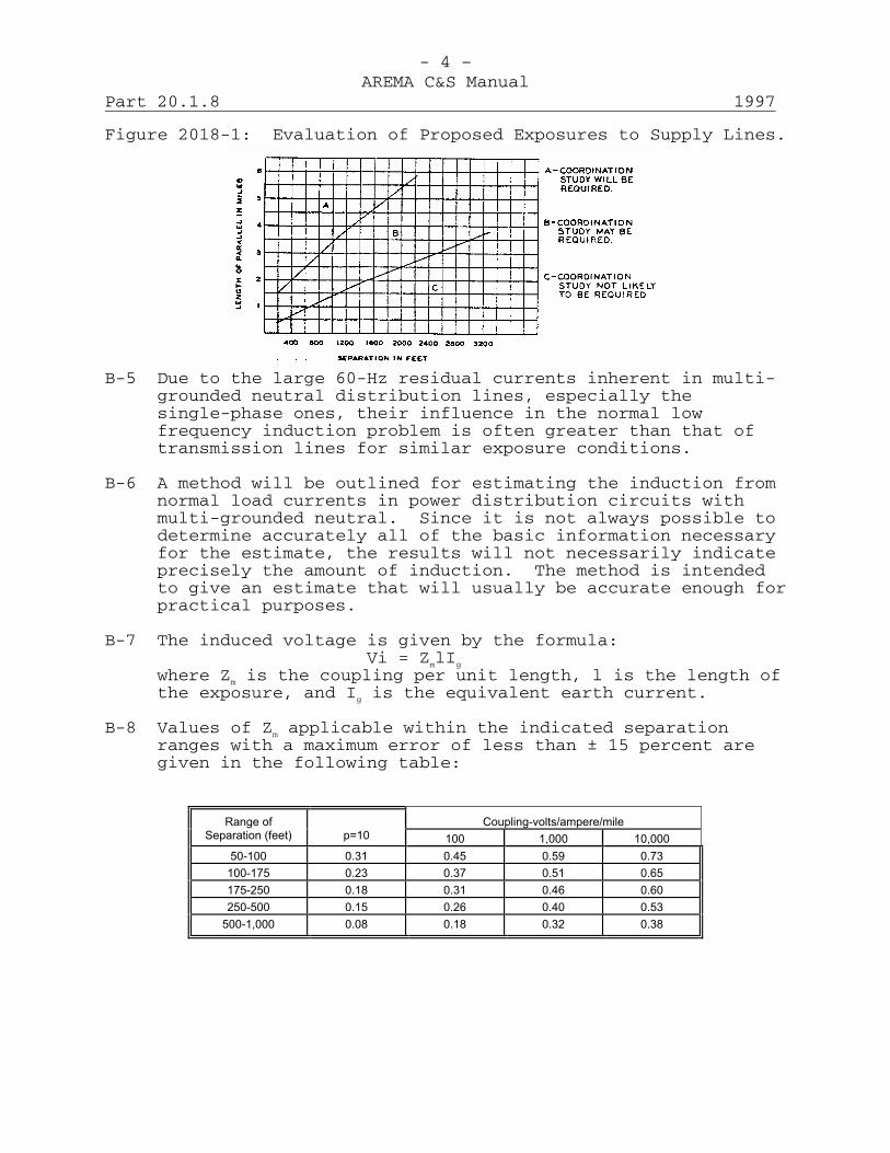
- 4 –AREMA C&S Manual
Part 20.1.8 1997
Figure 2018-1: Evaluation of Proposed Exposures to Supply Lines.
B-5 Due to the large 60-Hz residual currents inherent in multi-grounded neutral distribution lines, especially thesingle-phase ones, their influence in the normal lowfrequency induction problem is often greater than that oftransmission lines for similar exposure conditions.
B-6 A method will be outlined for estimating the induction fromnormal load currents in power distribution circuits withmulti-grounded neutral. Since it is not always possible todetermine accurately all of the basic information necessaryfor the estimate, the results will not necessarily indicateprecisely the amount of induction. The method is intendedto give an estimate that will usually be accurate enough forpractical purposes.
B-7 The induced voltage is given by the formula:Vi = ZmlIg
where Zm is the coupling per unit length, l is the length ofthe exposure, and Ig is the equivalent earth current.
B-8 Values of Zm applicable within the indicated separationranges with a maximum error of less than ± 15 percent aregiven in the following table:
Coupling-volts/ampere/mile
Range of
Separation (feet)
p=10 100
1,000
10,000
50-100
0.31
0.45
0.59
0.73 100-175
0.23
0.37
0.51
0.65
175-250
0.18
0.31
0.46
0.60 250-500
0.15
0.26
0.40
0.53
500-1,000
0.08
0.18
0.32
0.38
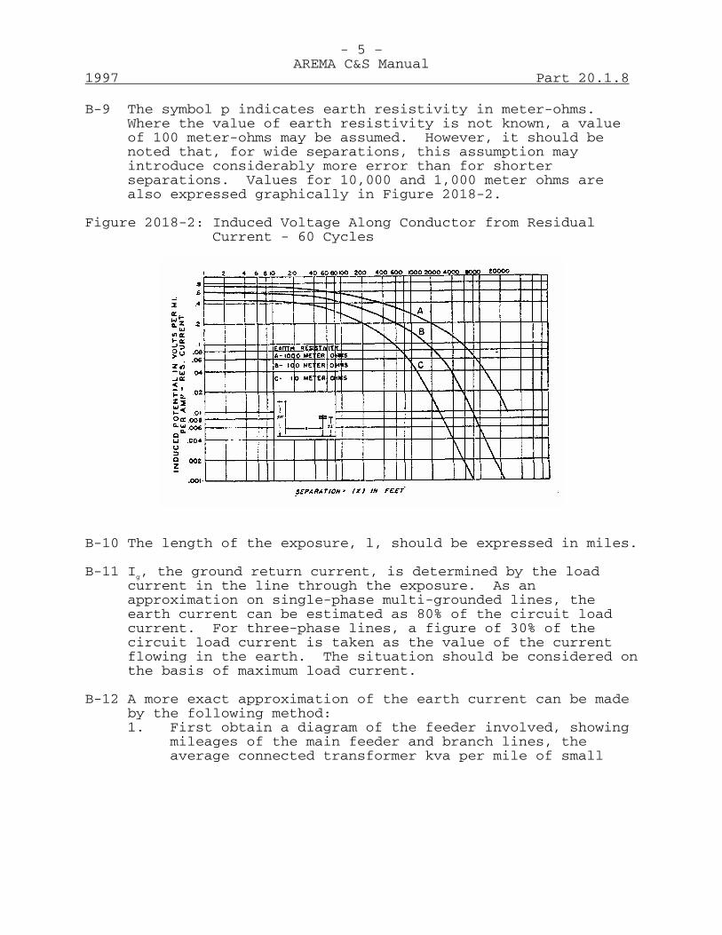
- 5 –AREMA C&S Manual
1997 Part 20.1.8
B-9 The symbol p indicates earth resistivity in meter-ohms.Where the value of earth resistivity is not known, a valueof 100 meter-ohms may be assumed. However, it should benoted that, for wide separations, this assumption mayintroduce considerably more error than for shorterseparations. Values for 10,000 and 1,000 meter ohms arealso expressed graphically in Figure 2018-2.
Figure 2018-2: Induced Voltage Along Conductor from ResidualCurrent - 60 Cycles
B-10 The length of the exposure, l, should be expressed in miles.
B-11 Ig, the ground return current, is determined by the loadcurrent in the line through the exposure. As anapproximation on single-phase multi-grounded lines, theearth current can be estimated as 80% of the circuit loadcurrent. For three-phase lines, a figure of 30% of thecircuit load current is taken as the value of the currentflowing in the earth. The situation should be considered onthe basis of maximum load current.
B-12 A more exact approximation of the earth current can be madeby the following method:1. First obtain a diagram of the feeder involved, showing
mileages of the main feeder and branch lines, theaverage connected transformer kva per mile of small

- 6 –AREMA C&S Manual
Part 20.1.8 1997
transformers, plus size and location of large ones,exclusive of three-phase banks.
2. Determine the demand factor, that is, the ratio of themaximum kva demand on the feeder to the total connectedtransformer kva. In the absence of more accurateinformation a demand factor of 0.5 may be used.
3. Determine the size of the neutral conductor making upthe major portion of the feeder.
4. Determine the length and location of the exposure.
5. If data are readily available, determine the earthresistivity.
6. Plot a diagram of the exposure showing points whereimportant branch lines leave the main feeder.
B-13 From the information as to connected transformers kva assignas an equivalent load at the end of the exposure furthestremoved from the source of power, the total kva oftransformers connected to the feeder and its branches beyondthat point, plus one-half of the total kva of transformersdistributed through the exposure. At points within theexposure where there are large concentrated loads or wherebranch lines leave the feeder, assign an equivalent loadequal to the total connected transformer kva of the load orbranch.
B-14 Find the currents due to the various equivalent loads bymultiplying the kva of each by the demand factor anddividing by the nominal line to neutral voltage.
B-15 Where the currents so determined apply to sections of theexposure, as in the case of branch lines or concentratedloads within the exposure, determine an equivalent currentapplicable to the entire exposure by multiplying the sectioncurrent by the ratio ls/lt, where ls is the distance fromthe end of the exposure nearest the supply substation toload or branch line, and lt the total length of exposure.

- 7 –AREMA C&S Manual
1997 Part 20.1.8
B-16 Add directly the individual equivalent currents sodetermined to obtain a total equivalent current (I). Findthe corresponding earth current Ig, where Ig = KI amperes.
B-17 For neutral conductor approximate K values are:
Conductor Size K Value
No. 2 copper or equivalent.................. 0.65
No. 4 copper or equivalent.................. 0.75
No. 6 copper or equivalent.................. 0.85
No. 8 copper or equivalent.................. 0.9
B-18 This value of Ig can be used in the formula Vi = ZmlIg asexplained previously.
B-19 If there are major variations in separation or shield factor(K) within the exposure, divide it into sections of fairlyuniform separation and shield factor and apply the aboveprocedure, treating each section as a separate exposure.Add directly the induced voltages found for each section todetermine the total voltage.
B-20 In computing normal 60-Hz magnetic induction fromtransmission lines, there are a number of factors that mustbe evaluated. These include:1. Induction from the balanced currents.
2. Induction from the ground return currents that flow inthe overhead ground wires of the transmission line as aresult of induction into these ground wires from thephase currents.
3. Induction from the residual currents flowing in thetransmission line phase conductors.
B-21 In a specific case the magnitude of induced magneticpotential from balanced three-phase circuits dependssomewhat on the configuration and spacing of the powerconductors. Figures 2018-3 and 2018-4 are typical curvesfor coupling coefficients. These coefficients are expressedin volts per mile per 100 amp. of balanced
- 8 –AREMA C&S Manual
Part 20.1.8 1997
current. These curves apply to average soil conditions andare valid only for 60-Hz currents.
B-22 The induction from the overhead ground wires is most likelyto be important where high conductivity ground wires areused. Steel ground wires in the smaller sizes, around3/8-in. diameter, offer sufficiently high impedance to theflow of current that their inductive effect will usually beless than that from the balanced currents.
B-23 The residual current in the phase conductors is an unknownquantity when a proposed exposure is under consideration.Sixty Hertz residual currents of 5 to 10 amp. are notunusual and may be used for estimating purposes. Theinduced voltage from such residual currents is computed bythe formula in Paragraph B-7, and adds to the inducedvoltage from the three-phase balanced currents.
B-24 This section left blank.
B-25 Induction into dc grounded telegraph circuits below 10 voltswill usually not be troublesome; voltages between 10 and 25volts are likely to require remedial measures and voltagesin excess of 25 volts will definitely require correction.Due consideration must be given to existing induction on thecircuits in question. Higher speed telegraph circuitsapproaching 60-Hz operation will suffer comparableimpairment at lower induced voltages than those named above.For metallic operations considerably higher voltages thanthose referred to may be tolerated.
B-26 Normal low frequency induction has been known to interferewith 60-cycle signal systems operated by track circuits.
C - Abnormal Low Frequency InductionC-1 The purpose of this section is to describe methods of
determining whether the low frequency induction from supplysystem short circuit currents to ground warrants remedialmeasures, and if so, to what extent such measures should beundertaken. Abnormal low frequency induction affects bothground return and metallic communication circuits. Itresults from high ground return currents that occur at timesof ground faults on neighboring supply systems and itscharacteristic is, therefore, one of relatively high inducedvoltages of short duration. The effects on thecommunication system vary over a wide range from
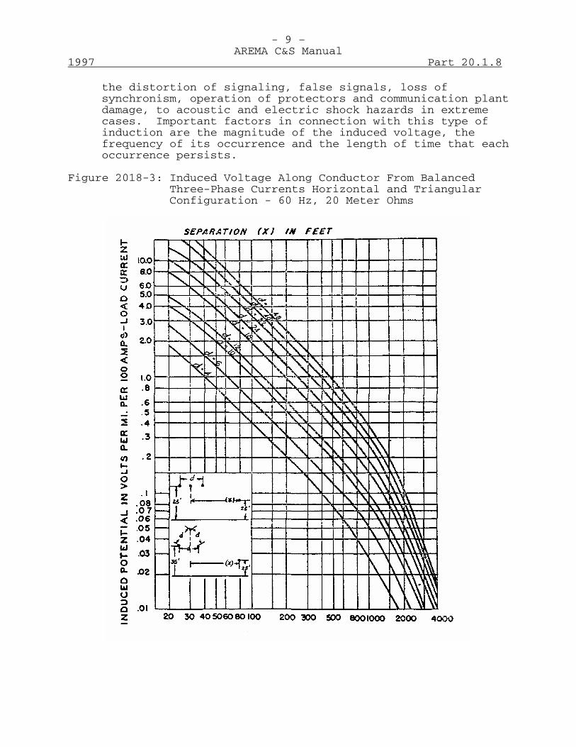
- 9 –AREMA C&S Manual
1997 Part 20.1.8
the distortion of signaling, false signals, loss ofsynchronism, operation of protectors and communication plantdamage, to acoustic and electric shock hazards in extremecases. Important factors in connection with this type ofinduction are the magnitude of the induced voltage, thefrequency of its occurrence and the length of time that eachoccurrence persists.
Figure 2018-3: Induced Voltage Along Conductor From BalancedThree-Phase Currents Horizontal and TriangularConfiguration - 60 Hz, 20 Meter Ohms
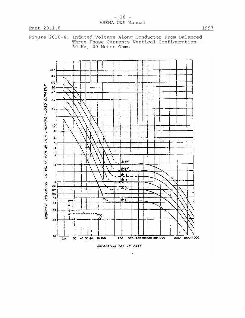
- 10 –AREMA C&S Manual
Part 20.1.8 1997
Figure 2018-4: Induced Voltage Along Conductor From BalancedThree-Phase Currents Vertical Configuration -60 Hz, 20 Meter Ohms
- 11 –AREMA C&S Manual
1997 Part 20.1.8
C-2 This section covers analyses of both proposed and existingsituations. The same data are required for both, theprincipal difference being in the manner of obtaining theinformation and its reliability. For example, coupling canoften be obtained by direct measurements on the circuitsinvolved in an existing exposure whereas for a proposedexposure, other means must be used. Also in existingexposures the frequency of faults on the power system andthe troubles experienced in the communication system areknown whereas an estimate of these must be made for aproposed exposure.
C-3 Because of the many factors involved in low frequencyinduction, it is not practical to set definite limits forthe magnitude of the voltage which can be tolerated in thecommunication plant from the standpoint of safety andservice reactions. Therefore, to provide a basis forappraising the possible effects of a particular exposure, itis suggested that information be prepared on certain factorsthat will enable estimates of the following type to beprepared.1. Service Reactions: Estimated frequency of occurrence
and number of momentary protector block operations.
Estimated frequency of occurrence and number ofprotector operations resulting in permanently groundedblocks.
2. Safety: Estimated miles of communication linesubjected to significant voltages; the frequency ofoccurrence of these voltages and their duration. Theseestimates should include voltage differences betweenconductors and between conductors and ground orgrounded metallic objects, and voltages across an"open" conductor.
C-4 The service reactions and hazards of low frequency inductionare subject to wide variations and estimates of thesefactors will not have a high degree of precision.Furthermore, in some phases of the study, roughapproximations must be used. On the other hand, reasonableaccuracy is practical and should be obtained in connectionwith the fault currents, coupling, fixed shielding, etc.
- 12 –AREMA C&S Manual
Part 20.1.8 1997
C-5 General Procedure in Analyzing Problems: An analysis of aninductive exposure situation should, in general, cover thesteps given below.1. Estimates or measurements of coupling, including all
shielding except that due to grounded communicationconductors and cable sheaths.
2. Magnitude and duration of fault currents through theexposure.
3. Estimates of primary field calculated as the product ofthe coupling determined in (1) and the magnitude offault current determined in (2).
4. Estimates of shield factor for grounded communicationcable sheaths, and normally grounded communicationconductors.
5. Estimate of shielded longitudinal voltage as product of(3) and (4). This is called herein longitudinalinduced voltage.
6. Estimates of voltages across protectors* and thelikelihood of protector operation for selected faultlocations.
7. Determination of approximate number of protectorslikely to be operated for selected fault locations.
8. Determination of current through protectors and thelikelihood of permanent protector grounding forselected fault locations.
C-6 For a complete analysis of an inductive problem otherfactors should also be considered such as:1. Voltage distribution for selected fault locations:
a. Conductor voltage to ground or to sheath.b. Voltage between conductors.c. Voltage across an open in a conductor.
* Actually the voltage across protector blocks cannot exceed the operatingvoltage of the block. Here, and in the following, the expression "voltageacross protectors" means the voltage that would exist at a given point if theprotector blocks were removed.

- 13 –AREMA C&S Manual
1997 Part 20.1.8
2. Average frequency of occurrence of faults over thepower line. (Faults per 100 miles of power line peryear.)
3. Determination of miles of power line over which faultsat different locations will produce significantvoltages and currents.
4. Miles of communication line subjected to differentvalues of voltage for various power line faultlocations and frequency of occurrence of such faults.(Fault-mile products.)
It is usually difficult to obtain accurate dataregarding many of these factors, consequently adetailed discussion is not included.
C-7 In certain cases, a preliminary analysis, consisting only ofthe first few steps necessary for a complete study, maydevelop that a particular problem can be dismissed with nofurther work. For example, preliminary scrutiny indicatingthat voltages induced will be below protector breakdown mayshow no further study necessary if the durations of faultcurrents are not over two or three seconds. If the numberof faults that might result in voltages above protectorbreakdown is large, or if a border line case is indicated, afairly complete study should be made, and in more severecases complete studies are necessary.
C-8 The importance of an inductive exposure is determined byconsiderations of both service reactions and safety-not byany single factor such as the magnitude of the longitudinalinduced voltage. As explained below, the appraisal ofservice reactions is based on a consideration of how manyand how often protectors are likely to be operated orpermanently grounded. The appraisal of safety is based on aconsideration of the frequency of occurrence of significantvoltages, their duration, the number of miles ofcommunication line subjected to these voltages, etc.
Detailed Procedure in Analyzing ProblemsC-9 Coupling: As indicated in Paragraph C-5, it is usually
desirable to determine first the coupling between the powerand communication circuits including shielding effects ofground wires on the power line and of other conducting pathsnot associated with the communication line. The
- 14 –AREMA C&S Manual
Part 20.1.8 1997
product of this coupling factor and the fault currentthrough the exposure is the primary field, which excludesthe effect of shielding from conductors on the communicationline. The longitudinal induced voltage is found bymultiplying the value of primary field by the shield factorfor the communication cable sheath (if any) and normallygrounded conductors. In some cases the coupling and shieldfactors can be estimated with sufficient accuracy(ER*-14,26,48), while in other cases the coupling andshielding must either be measured directly or computed withthe assistance of measurements of earth resistivity (seeSection D). The importance of earth resistivity dependsupon the separation between the power and communicationcircuits. For example, a 100 to 1 change in earthresistivity results in less than a 2 to 1 change in 60-Hzcoupling at about a 60-ft. separation, but approximately a30 to 1 change in coupling at a separation of 5,000 ft.
C-10 Paragraph B-8 and Figure 2018-2 give information by whichcoupling factors can be readily estimated and the primaryfield calculated for particular conditions, provided a highdegree of accuracy is not required. TO obtain a higherdegree of accuracy actual coupling between power andcommunication circuits should be obtained by measurements.
C-11 Magnitude and Duration of Fault Currents: The magnitudesand durations of fault currents for use in analyzing aninductive problem should be arrived at only after consultingthe power company involved as suggested in Paragraph A-8.In some situations, particularly for exposures to relativelyshort power lines, fault resistance is an important factorin determining fault current and a choice for its value foruse in calculations should be made only after carefulconsideration. The results of extensive joint testsindicate that where fault resistance is to be allowed for infault current computations, 20 ohms for line and 5 ohms forsubstation ground faults are reasonable values to use(ER-39).
* ER-Engineering Reports of the Joint Subcommittee on Development andResearch of the Edison Electric Institute and Bell Telephone System.
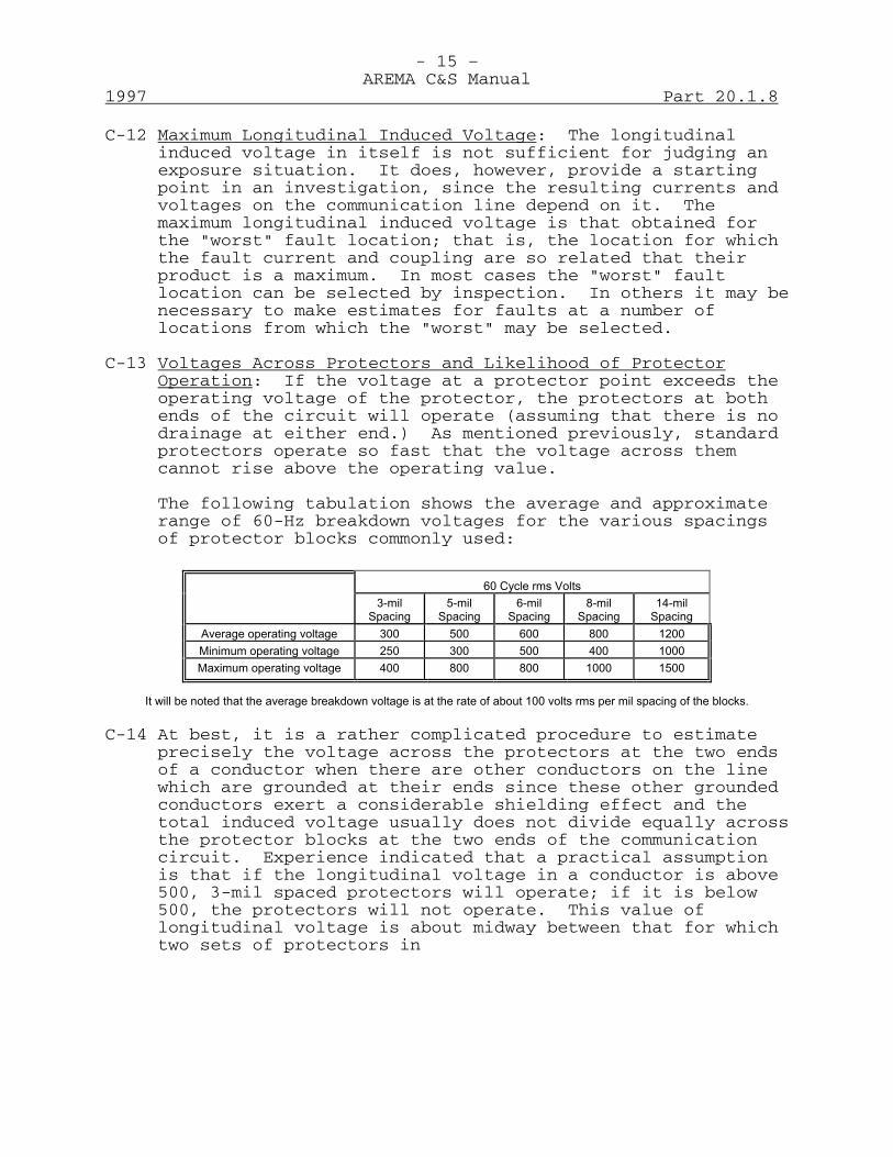
- 15 –AREMA C&S Manual
1997 Part 20.1.8
C-12 Maximum Longitudinal Induced Voltage: The longitudinalinduced voltage in itself is not sufficient for judging anexposure situation. It does, however, provide a startingpoint in an investigation, since the resulting currents andvoltages on the communication line depend on it. Themaximum longitudinal induced voltage is that obtained forthe "worst" fault location; that is, the location for whichthe fault current and coupling are so related that theirproduct is a maximum. In most cases the "worst" faultlocation can be selected by inspection. In others it may benecessary to make estimates for faults at a number oflocations from which the "worst" may be selected.
C-13 Voltages Across Protectors and Likelihood of ProtectorOperation: If the voltage at a protector point exceeds theoperating voltage of the protector, the protectors at bothends of the circuit will operate (assuming that there is nodrainage at either end.) As mentioned previously, standardprotectors operate so fast that the voltage across themcannot rise above the operating value.
The following tabulation shows the average and approximaterange of 60-Hz breakdown voltages for the various spacingsof protector blocks commonly used:
60 Cycle rms Volts
3-mil Spacing
5-mil
Spacing
6-mil
Spacing
8-mil
Spacing
14-mil
Spacing Average operating voltage
300
500
600
800
1200
Minimum operating voltage
250
300
500
400
1000 Maximum operating voltage
400
800
800
1000
1500
It will be noted that the average breakdown voltage is at the rate of about 100 volts rms per mil spacing of the blocks.
C-14 At best, it is a rather complicated procedure to estimateprecisely the voltage across the protectors at the two endsof a conductor when there are other conductors on the linewhich are grounded at their ends since these other groundedconductors exert a considerable shielding effect and thetotal induced voltage usually does not divide equally acrossthe protector blocks at the two ends of the communicationcircuit. Experience indicated that a practical assumptionis that if the longitudinal voltage in a conductor is above500, 3-mil spaced protectors will operate; if it is below500, the protectors will not operate. This value oflongitudinal voltage is about midway between that for whichtwo sets of protectors in
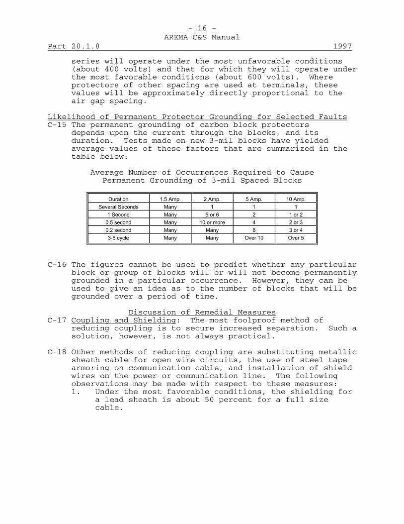
- 16 –AREMA C&S Manual
Part 20.1.8 1997
series will operate under the most unfavorable conditions(about 400 volts) and that for which they will operate underthe most favorable conditions (about 600 volts). Whereprotectors of other spacing are used at terminals, thesevalues will be approximately directly proportional to theair gap spacing.
Likelihood of Permanent Protector Grounding for Selected FaultsC-15 The permanent grounding of carbon block protectors
depends upon the current through the blocks, and itsduration. Tests made on new 3-mil blocks have yieldedaverage values of these factors that are summarized in thetable below:
Average Number of Occurrences Required to CausePermanent Grounding of 3-mil Spaced Blocks
Duration
1.5 Amp.
2 Amp.
5 Amp.
10 Amp.
Several Seconds
Many
1
1
1 1 Second
Many
5 or 6
2
1 or 2
0.5 second
Many
10 or more
4
2 or 3 0.2 second
Many
Many
8
3 or 4
3-5 cycle
Many
Many
Over 10
Over 5
C-16 The figures cannot be used to predict whether any particularblock or group of blocks will or will not become permanentlygrounded in a particular occurrence. However, they can beused to give an idea as to the number of blocks that will begrounded over a period of time.
Discussion of Remedial MeasuresC-17 Coupling and Shielding: The most foolproof method of
reducing coupling is to secure increased separation. Such asolution, however, is not always practical.
C-18 Other methods of reducing coupling are substituting metallicsheath cable for open wire circuits, the use of steel tapearmoring on communication cable, and installation of shieldwires on the power or communication line. The followingobservations may be made with respect to these measures:1. Under the most favorable conditions, the shielding for
a lead sheath is about 50 percent for a full sizecable.

- 17 –AREMA C&S Manual
1997 Part 20.1.8
2. Shield wires of practicable sizes on either power orcommunication lines do not usually provide shielding ofover 50%. In communication cables, additional lowfrequency shielding can be obtained if copper is addedas circuits rather than as separate shield wires.
3. Generally, tape armoring provides a higher degree ofshielding than shield wires.
4. Low resistance grounds on the sheath or other shieldconductors are essential to obtain maximum shielding.
C-19 Power System Influence: Various developments in the powerindustry during recent years have had a definitely favorablereaction on low frequency inductive coordination. The mostsignificant of these are measures taken to reduce thefrequency of occurrence of ground faults which cause powerline outages, and measures to insure more prompt clearanceof such faults.
C-20 On several occasions, residual current limitation has beenused as a means of reducing power system influence. Theusual form of such limitation involves resistance orreactance in the neutral-to-ground connections of importanttransformer supply banks (ER-27). The type and amount ofneutral impedance that can be used in any power systemdepends upon system layout, insulation levels, relayingsystems, etc. The effect on low frequency induction of suchcurrent limitation can be summarized as follows:
1. For exposures near the power supply point, the hazardto workmen due to induced voltages frequently can bereduced by the use of relatively small values ofneutral impedance.
2. For exposures remote from the source of supply,comparatively large values of neutral impedance wouldbe required and these frequently are impracticable.
3. There is a tendency for power system relaying to becomeslower and less positive where large values of neutralimpedance are used. This may actually increase theinfluence of the system.
C-21 From the standpoint of limiting ground fault currents, aspecial form of neutral impedance known as the Petersen

- 18 –AREMA C&S Manual
Part 20.1.8 1997
coil, or "ground-fault neutralizer" or "resonant" groundingis probably the most satisfactory. In the United States theuse of the Petersen coil is limited to a large extent tosituations where special kinds of power operating problemsexist. The Petersen coil however acts to increase the60-cycle residual current during normal operation of thepower system.
C-22 Communication System Susceptiveness: The two measures whichare most widely used now to reduce the susceptiveness ofcommunication systems to low frequency induction areshort-circuiting relay protectors (ER-41) and drainage. Themore important differences between relay protectors andordinary protectors can be summarized as follows:
1. The multi-grounding type of relay protector is usedextensively for the reduction of hazard. With thistype all wires are grounded whenever any protector inthe group operates, thus insuring shielding from all ofthe wires in the group. By the same token, potentialdifferences between wires at the protector point arebrought essentially to zero.
2. With multi-grounding type relay protectors certaincircuits on the line may be short-circuited andgrounded at times when the protectors on them would nototherwise be operated. Hence in cases where, in theabsence of relay protectors, only a small proportion ofthe regular protectors would operate, the service maybe impaired. On the other hand, in cases where theregular protectors on most of the circuits wouldoperate, the service may be improved by relayprotectors, and in particular, where permanentgrounding of regular protectors may occur, theimprovement in service may be relatively large.
3. If multi-grounding relay protector installations areappropriately placed, substantial reductions involtage-to-ground hazards can be secured, and voltagedifferences at cable poles can be virtually eliminated.
4. Unit type relay protectors, also known as arresterrelays, are frequently used to improve service bypreventing permanent grounding of regular protectors.
- 19 –AREMA C&S Manual
1997 Part 20.1.8
C-23 The location of relay protectors should be such as toprovide the largest possible reduction in hazard from aminimum number of installations. Locations at or nearcommunication entrance cable poles are frequently desirablesince relay protectors at such locations often give maximumeffectiveness, cable sheaths can often be used for ground,and maintenance is facilitated. Installations at otherpoints frequently involve "making" low resistance grounds,which in some cases may be expensive and difficult. In somecases, of course, relay protector installations can belocated in towns or other places where water pipes or otherextensive grounding structures are available.
C-24 Drainage can sometimes be used to eliminate even momentaryprotector operation on metallic circuits used only for voiceor carrier transmission. A physical circuit is drainedsimply by connecting the drainage coil across the line withwindings in series-aiding and with the neutral pointgrounded. A phantom group requires three coils at eachdrainage point, a single coil being connected across eachside circuit, the neutral points of which connect to theline terminals of the third coil, and the neutral of thisthird coil is grounded.
C-25 Acoustic shock may be caused by a high induced voltageoperating a protector or otherwise breaking down theinsulation on one side of a telephone circuit or byoperating the arresters on the two sides of a pair un-symmetrically. Under such conditions, the differencebetween the voltages simultaneously appearing in the twosides of the circuit causes a discharge of current throughthe terminal apparatus.
C-26 The device known as the varistor, which consists of anassembly of copper oxide discs, has been used widely as ameans for reducing acoustic shock. This device has theproperty of decreasing its resistance with increase involtage across its terminals, that is, when such a device isplaced across the circuit, the shunting effect increaseswith increasing voltage.
D - Noise Frequency InductionD-1 Introduction: This section discusses the general principles
and procedures involved in determining the technicalsolution to a noise frequency inductive coordinationproblem. It is based largely on experience in
- 20 –AREMA C&S Manual
Part 20.1.8 1997
many such situations and an attempt has been made tosummarize this experience as concisely as practicable.
D-2 It is obviously impractical to set down any procedure thatwill be universally applicable to all noise problems. Thereis too much variety among problems. However, experience hasshown that there are several methods of approach and thissection is designed to be of help in finding the method mostlikely to secure the best overall results.
D-3 This section has been prepared to meet the needs of thefollowing:1. The engineer who has had little or no experience with
noise coordination problems, but who wishes to becomegenerally familiar with the fundamentals and methods ofattack and to know where to find detailed informationon particular phases of the work.
2. The experienced coordination engineer who wishes aready reference to the available material for use inhis day-to-day problems.
3. The supervisor who wishes to have a broad picture ofthe essential factors involved in noise coordinationproblems.
To meet these needs the discussion of the body of thesection assumes knowledge of the meanings of the specialterms used in noise coordination studies and of the physicalprocesses of induction. However, explanations of thesefundamental ideas are given in Section A of the Manual Part7-7.
D-4 It is essential to keep in mind that inductive coordinationis a mutual problem that must be handled cooperatively withthe power organizations. Technically sound solutions toproblems cannot be expected unless the relations with thepower organizations are on a sound basis and sound relationscannot be long maintained unless technically sound solutionsto specific problems are secured. This is not a newthought, nor is it difficult to understand its importance,but situations sometimes arise in which it seems evidentthat its full significance is not appreciated.

- 21 –AREMA C&S Manual
1997 Part 20.1.8
D-5 Experience has indicated very definitely that in order toarrive at technically sound solutions there are a number ofprinciples that must be observed. Furthermore suchexperience has clearly shown that failure to observe any oneof these principles may and frequently does lead tounsatisfactory results in specific cases or tounsatisfactory relations or to both. These principles areoutlined below.
1. Do not try to arrive at a conclusion without sufficientfacts. Both the facts and the conclusions should bearrived at cooperatively with the power organization.
2. Weigh the various factors involved in a problemproperly. For example, do not concentrate on somefactor which may be the cause of high influence andneglect a possible cause of high susceptiveness, and donot spend too much time correcting the source of 15 dbof noise while leaving a source of 40 db uncorrected.
3. Wherever practicable use measured rather than computedvalues. No matter how precisely computations are made,the results are no more accurate than the data orassumptions on which they are based. There are fewthings as detrimental to sound conclusions (or torelations) as the use of values purporting to becorrect to three or four significant figures when theassumptions on which they are based may be off two ormore to one.
4. Remember that a power man knows more about the powerbusiness than a communication man and is the one whoshould determine what can and what cannot be done onhis system.
5. Remember that a power man ordinarily has no particularreason or incentive to take the lead in solving aninductive coordination problem. It is up to thecommunication man to follow up each situation and tocarry out any arrangements made with the power man atthe earliest practicable moment.
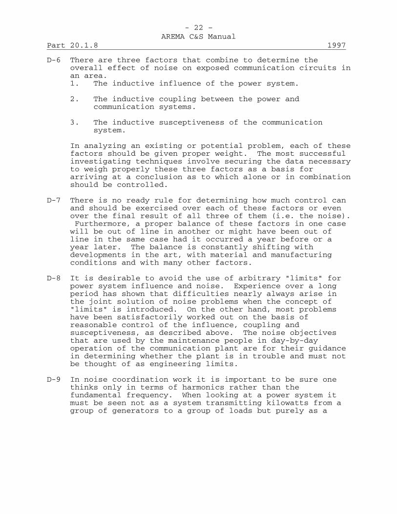
- 22 –AREMA C&S Manual
Part 20.1.8 1997
D-6 There are three factors that combine to determine theoverall effect of noise on exposed communication circuits inan area.1. The inductive influence of the power system.
2. The inductive coupling between the power andcommunication systems.
3. The inductive susceptiveness of the communicationsystem.
In analyzing an existing or potential problem, each of thesefactors should be given proper weight. The most successfulinvestigating techniques involve securing the data necessaryto weigh properly these three factors as a basis forarriving at a conclusion as to which alone or in combinationshould be controlled.
D-7 There is no ready rule for determining how much control canand should be exercised over each of these factors or evenover the final result of all three of them (i.e. the noise).Furthermore, a proper balance of these factors in one casewill be out of line in another or might have been out ofline in the same case had it occurred a year before or ayear later. The balance is constantly shifting withdevelopments in the art, with material and manufacturingconditions and with many other factors.
D-8 It is desirable to avoid the use of arbitrary "limits" forpower system influence and noise. Experience over a longperiod has shown that difficulties nearly always arise inthe joint solution of noise problems when the concept of"limits" is introduced. On the other hand, most problemshave been satisfactorily worked out on the basis ofreasonable control of the influence, coupling andsusceptiveness, as described above. The noise objectivesthat are used by the maintenance people in day-by-dayoperation of the communication plant are for their guidancein determining whether the plant is in trouble and must notbe thought of as engineering limits.
D-9 In noise coordination work it is important to be sure onethinks only in terms of harmonics rather than thefundamental frequency. When looking at a power system itmust be seen not as a system transmitting kilowatts from agroup of generators to a group of loads but purely as a

- 23 –AREMA C&S Manual
1997 Part 20.1.8
system composed of inductances, capacitances and resistanceswith one or more sources of harmonics on it. Where theseharmonics originate, where they go, how they are attenuatedor amplified (as by resonance) usually bear little or norelation to the 60 Hz characteristics.
D-10 The results of noise tests on poorly balanced communicationcircuits (where the unbalance is due to poor maintenance)should never form the basis for negotiations with a powercompany concerning a noise problem. Where extensions of orchanges in a power system have caused noise increases, orexposed circuits, it may be desirable to investigateinfluence, coupling and susceptiveness conditionscooperatively, before reaching conclusions that improvedbalance is desirable.
General ConsiderationsD-11 Certain general considerations common to all types of noise
frequency induction studies are discussed below withreferences to related material that gives detaileddiscussions of the various factors.
D-12 Layout of Power and Communication Facilities: The firststep in any general survey of noise conditions or in aninvestigation of a specific noise case is to obtainup-to-date information on the layout of the power andcommunication systems involved in the problem. There isprobably no greater single cause of delay in solving suchproblems than an attempt to proceed without adequateinformation of this type. These data will normally includeinformation on the relative locations of the power andtelephone circuits involved, the type of power system,source of supply for the particular feeders underconsideration, transformer connections, etc., as well as thetypes of communication circuits and equipment used. Groundconnections and continuity of any telephone cable sheathsinvolved in a specific noise problem should be carefullychecked. Such data should normally be available in therecords of the power and communication companies, but, ifthere is a possibility of the records not being kept up todate, these will need to be carefully checked at the startof the study. A brief description of the physical situationand of the power and telephone equipment involved shouldalways form part of the report covering the test results.(See Paragraphs D-50 to D-53, inclusive.)

- 24 –AREMA C&S Manual
Part 20.1.8 1997
D-13 The information on the power and communication system layoutand type should be "adequate" in all cases; the type andamount of information to be assembled should be carefullyconsidered in the light of the nature and extent of theproblem. It is undesirable to attempt to secure moredetailed information than is necessary, particularly when itinvolves asking a power company to prepare and furnishinformation on every detail of an extensive system. Whileconsiderable experience is necessary before completely soundjudgment can be exercised in this important matter, theprinciples involved are briefly outlined below and will bemade clearer from study of the remaining parts of thissection.1. The first principle is to decide what the general scope
of the problem is or is likely to be, viz.:a. Is it a specific problem involving only one or
more exposures?
b. Is it a general problem that extends or may extendover a substantial area and involve a considerable(and possibly unknown) number of exposures?
2. If on class (1-a), it usually is desirable to secureinformation pertaining to the exposures and circuits inconsiderable detail.
3. If the class (1-b), more general information is usuallysufficient - e.g. single line diagrams and geographiclayouts of the power transmission system, and generaldescriptions of the communications system giving thelocations and rough dimensions of exposures but notgoing into much detail on either system.
4. Regardless of the general class of the problem,complete information on the power and communicationsystems in the vicinity of important sources ofharmonics or at points of high influence on the powersystem should be secured.
D-14 Influence, Coupling and Susceptiveness: In allinvestigations it is of primary importance to keep in mindthat every noise induction problem involves consideration ofthree major factors, (a) the inductive influence of thepower system, (b) the coupling between the power andcommunication lines, and (c) the susceptiveness of the
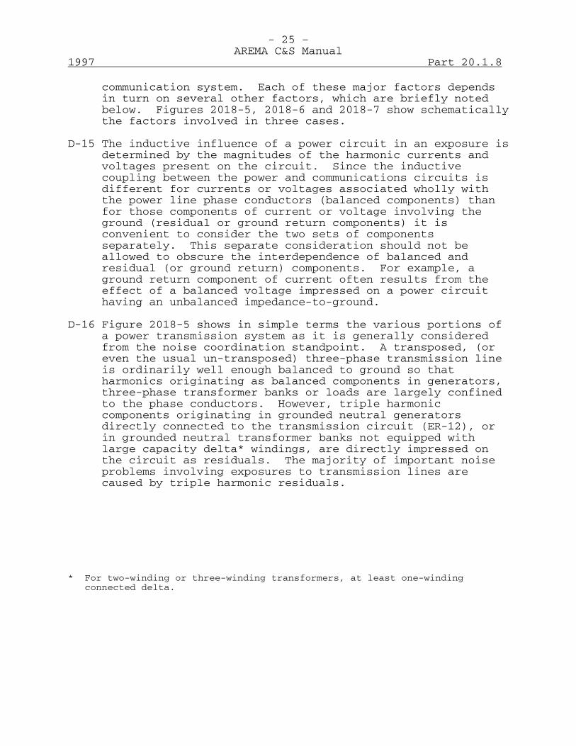
- 25 –AREMA C&S Manual
1997 Part 20.1.8
communication system. Each of these major factors dependsin turn on several other factors, which are briefly notedbelow. Figures 2018-5, 2018-6 and 2018-7 show schematicallythe factors involved in three cases.
D-15 The inductive influence of a power circuit in an exposure isdetermined by the magnitudes of the harmonic currents andvoltages present on the circuit. Since the inductivecoupling between the power and communications circuits isdifferent for currents or voltages associated wholly withthe power line phase conductors (balanced components) thanfor those components of current or voltage involving theground (residual or ground return components) it isconvenient to consider the two sets of componentsseparately. This separate consideration should not beallowed to obscure the interdependence of balanced andresidual (or ground return) components. For example, aground return component of current often results from theeffect of a balanced voltage impressed on a power circuithaving an unbalanced impedance-to-ground.
D-16 Figure 2018-5 shows in simple terms the various portions ofa power transmission system as it is generally consideredfrom the noise coordination standpoint. A transposed, (oreven the usual un-transposed) three-phase transmission lineis ordinarily well enough balanced to ground so thatharmonics originating as balanced components in generators,three-phase transformer banks or loads are largely confinedto the phase conductors. However, triple harmoniccomponents originating in grounded neutral generatorsdirectly connected to the transmission circuit (ER-12), orin grounded neutral transformer banks not equipped withlarge capacity delta* windings, are directly impressed onthe circuit as residuals. The majority of important noiseproblems involving exposures to transmission lines arecaused by triple harmonic residuals.
* For two-winding or three-winding transformers, at least one-windingconnected delta.

- 26 –AREMA C&S Manual
Part 20.1.8 1997
D-17 Figure 2018-6 shows a schematic diagram of a powerdistribution circuit and exposed communication plant thatconsists of aerial cable. Ordinarily a distribution systemfeeds a substantial portion of single-phase load and isinherently unbalanced to ground, because of the unequallengths of line associated with each phase. Consequentlynon-triple harmonic residual components arising insingle-phase load transformers, or as a result of balancedimpressed voltages acting on unbalanced system impedances toground, may be as important as, or more important than,triple harmonic components. (Under these conditions theusual distinction between triple and non-triple componentsloses much of its significance.) There are usually manyload transformers and loads connected to a distributionsystem and each of these is a potential source of harmonics.Consequently, the influence of a distribution system isaffected by many more factors than that of a transmissioncircuit connecting a point of generation with a load.
D-18 In Figure 2018-5, two separate components of coupling areshown between the power line and an exposed open wirecommunication line. Induction into an exposed communicationline is primarily longitudinal (Section B of Manual Part7-7) and direct metallic induction may be considered as thedifference between the unequal magnitudes of longitudinalinduction that act on two communication wires at differentspacings from the power line. It follows that if inductioninto the two wires is equalized either by properlycoordinated transpositions or by keeping the two wires ofthe pair close together (as in cable or drop wire, etc.),the effects of direct metallic induction can be made verysmall even though the longitudinal voltages (between wiresand ground) and longitudinal currents (flowing in the wireswith ground return) will still be present and will act onany series or shunt unbalances in the communication circuitor terminal equipment to produce metallic circuit noise.
D-19 The magnitude of the coupling for either direct metallic orlongitudinal induction depends upon the exposure length andthe separation between the power and communication lines.Coupling for ground return currents also depends upon thedistance of the ground return path below the power phasewires, but this is generally assumed as 400 ft. (200-ft.ground plane) in noise induction problems. Occasionally
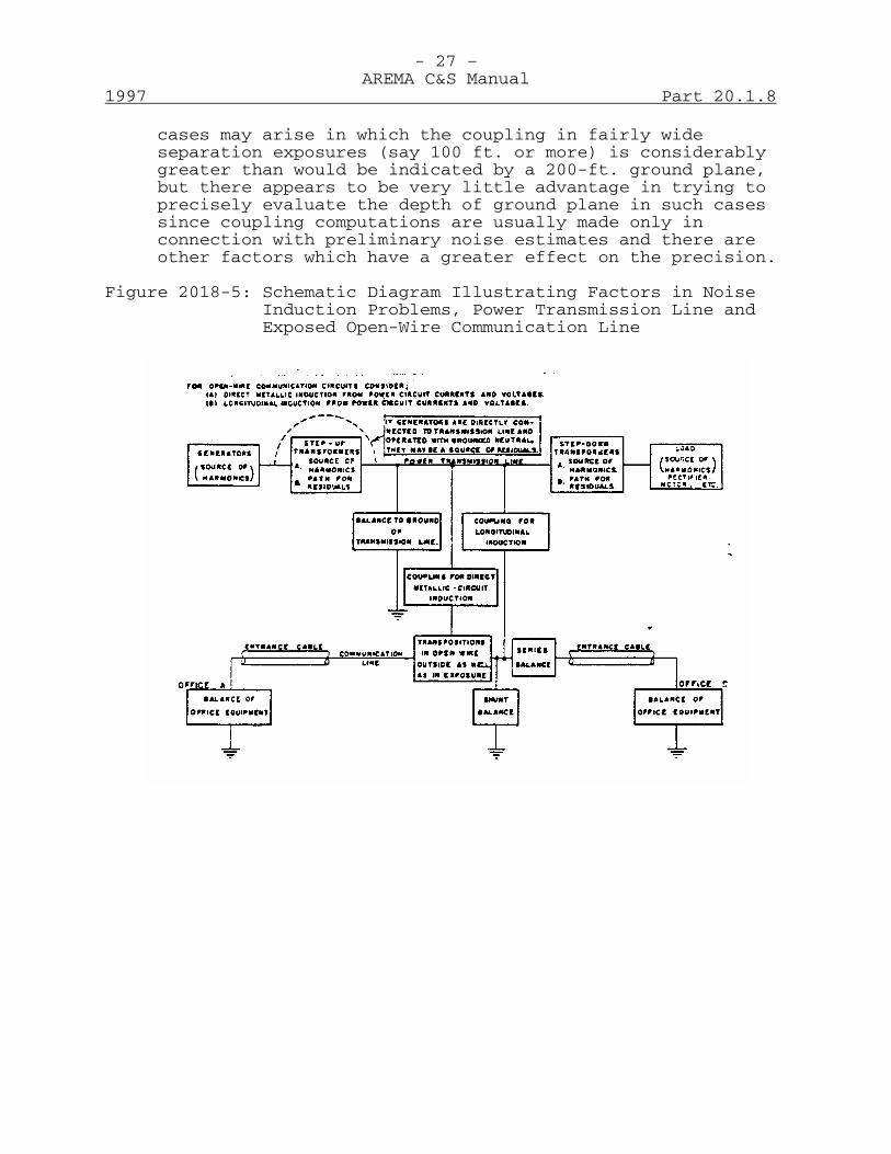
- 27 –AREMA C&S Manual
1997 Part 20.1.8
cases may arise in which the coupling in fairly wideseparation exposures (say 100 ft. or more) is considerablygreater than would be indicated by a 200-ft. ground plane,but there appears to be very little advantage in trying toprecisely evaluate the depth of ground plane in such casessince coupling computations are usually made only inconnection with preliminary noise estimates and there areother factors which have a greater effect on the precision.
Figure 2018-5: Schematic Diagram Illustrating Factors in NoiseInduction Problems, Power Transmission Line andExposed Open-Wire Communication Line

- 28 –AREMA C&S Manual
Part 20.1.8 1997
Figure 2018-6: Schematic Diagram Illustrating Factors in NoiseInduction Problems, Power Distribution Circuit andExposed Exchange Telephone Line in Aerial Cable
D-20 As shown in Figures 2018-5, 2018-6 and 2018-7, thesusceptiveness of a communication circuit depends upon theoverall effect of the transpositions (ER-16 and ER-17) (inthe case of open wire) and upon the series and shunt balanceof the line and on the balance of the terminal equipment.Ordinarily the design of long distance circuits in open wireand cable and of their associated terminal equipment is suchthat good balance should be secured. However, unless careis taken to insure that terminal apparatus is in goodcondition and is properly connected to the circuit, and toinsure good line conditions, circuit balance may be acontrolling factor in the noise on these circuits.
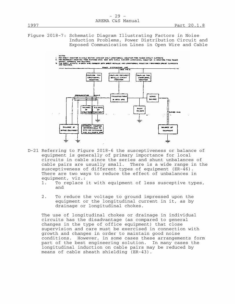
- 29 –AREMA C&S Manual
1997 Part 20.1.8
Figure 2018-7: Schematic Diagram Illustrating Factors in NoiseInduction Problems, Power Distribution Circuit andExposed Communication Lines in Open Wire and Cable
D-21 Referring to Figure 2018-6 the susceptiveness or balance ofequipment is generally of primary importance for localcircuits in cable since the series and shunt unbalances ofcable pairs are usually small. There is a wide range in thesusceptiveness of different types of equipment (ER-46).There are two ways to reduce the effect of unbalances inequipment, viz.:1. To replace it with equipment of less susceptive types,
and
2. To reduce the voltage to ground impressed upon theequipment or the longitudinal current in it, as bydrainage or longitudinal chokes.
The use of longitudinal chokes or drainage in individualcircuits has the disadvantage (as compared to generalchanges in the type of office equipment) that closesupervision and care must be exercised in connection withgrowth and changes in order to maintain good noiseconditions. However, in some cases these arrangements formpart of the best engineering solution. In many cases thelongitudinal induction on cable pairs may be reduced bymeans of cable sheath shielding (ER-43).

- 30 –AREMA C&S Manual
Part 20.1.8 1997
D-22 Figure 2018-7 illustrates the factors to be considered underconditions often encountered in the field involving circuitsin open wire and cable. In addition to metallic andlongitudinal induction, the diagram emphasizes thepossibility of secondary induction from certain cable pairs- which are connected to exposed open wire extensions - intoother pairs which do not have such extensions. A similarsituation may exist when open wire telephone circuits areconnected into a cable.
D-23 Overall Influence and Noise Measurements and HarmonicAnalyzes, Test Program: All test programs are usuallydirected toward securing data on existing or potential noisesituations and on the coupling, influence and susceptivenessfactors which contribute to that noise. Such a test programwill generally include noise measurements (metallic andto-ground or longitudinal), measurements of power systeminfluence and of the effects of changes (if any) in thecoupling.
D-24 Planning an adequate but not too elaborate test programpresents one of the most important, and most difficultproblems to the coordination engineer. No substitute hasbeen found for good judgment based on experience in layingout such a program. A few general principles based onexperience which may be helpful are listed below.
1. Determine what questions require answers concerningnoise, influence, coupling, and susceptiveness.Pertinent questions are likely to remain unansweredregardless of how much data are accumulated unless thepurpose of the tests is clear-cut.
2. A test or series of tests should be made which willanswer each of the questions in the most direct andsimplest manner practicable. Wherever a directmeasurement can be made, do not rely on an indirect one- and rely on computations only when a direct or anindirect measurement is not practicable.
3. The test program should be flexible enough to takeaccount of new facts that may be discovered as thetests proceed. Care must be taken, however, to preventbeing sidetracked from the main issues.

- 31 –AREMA C&S Manual
1997 Part 20.1.8
D-25 Coordination of Power and Communication System Tests:Whenever practicable, it is desirable to carry onsimultaneous measurements of power system influence andtelephone circuit noise. The advantages of being able totie together the effects of changes in the power andtelephone system on the influence and noise will usuallyjustify the extra personnel and apparatus required for suchsimultaneous measurements. Where it is impracticable toprovide for simultaneous tests, it is often necessary togive considerable study to the factors which control thevariations in the influence and noise over a period of time,as otherwise the test results are apt to lead to wrongconclusions.
D-26 Variation of Influence and Noise with Time: A number ofproblems have been investigated in which it was found that aknowledge of the variations in the power system influenceand resulting noise with time provided important clues tothe solution of the problem. For example, in locating asource of harmonic distortion on a power circuit, such as amotor, it has been found advantageous to make records of theresulting influence or noise in order to determine theoperating cycle of the particular motor as a clue to itslocation. Likewise, there are many cases where theinfluence of the power circuit varies considerably with theamount of load on the circuit (ER-40). In other cases ithas been found advantageous to set up a recordingarrangement at a particular point on a power system and thento survey influence or noise condition at other points usingthe record at the key point as an indication of any changesin conditions during the tests. Where recording equipmentis not available for this purpose, it may be desirable tohave an observer testing at the key point at all times whenmeasurements are being made at other points. With such anarrangement it has been possible to solve several problemsthat had previously been investigated over long periods by asingle test crew without success.
D-27 Noise Estimates vs. Measurements: In connection with noiseestimates (ER-16 and ER-17) following the principlesoutlined in the introduction to this section, computationsof noise should never be used in place of measurements,where tests are practicable. Estimates of noise metallicare likely to be unreliable unless a great deal ofinformation is available on power system influence, couplingand susceptiveness, most of which must be obtained
- 32 –AREMA C&S Manual
Part 20.1.8 1997
by measurement. On the other hand, computations may be veryhelpful in estimating the contributions of various types ofinduction or of particular communication plant unbalances toa known (measured) overall noise.
Power SystemsD-28 Types of Situations Likely to be Encountered: Several
different types of inductive coordination problems mayconfront the engineer and the procedure in determining thepower system influence will vary accordingly. For example,it may be desirable to investigate the effect of some knownchange in power system operation, such as the conversion ofa power circuit from one type of operation to another or theaddition of a new generator or piece of load equipment. Inthis case it is ordinarily desirable to start theinvestigation at the point where the change has been made,or where the equipment is being added, although it shouldnot be concluded if conditions are satisfactory there thatthe same is necessarily true at all other locations. On theother hand, the noise problem may arise from some unknowncause and it is often impossible to determine by discussionswith the power company exactly what change or changes mightbe responsible. This particularly is difficult when anumber of changes in operating conditions occur over a shortperiod in both the power and communications systems. Achange in power system operations that is responsible for achange in influence and noise may well be one that seems tohave little significance to the power people, who naturallyview their system primarily from the point of view ofsupplying power. For example, in one case it was found thata short length of distribution feeder had been disconnectedfrom one source of supply and connected to another. Theaddition of this length of line to the second system changedits impedance characteristics and introduced a condition ofresonance, which was responsible for a substantial increasein influence and noise. In cases like this theinvestigation of power system influence should commence inthe exposure section and work toward the source of harmonicdistortion or the cause of the condition of resonance.
D-29 Direct Measurements of Power System Influence: Wheresuitable current and potential transformers are availablefor measuring the influence of the harmonic currents andvoltages on the power system they should be used inpreference to any less direct method of test. Such
- 33 –AREMA C&S Manual
1997 Part 20.1.8
transformers are ordinarily available at generating plants,substations and at the points where fairly large loads arelocated. However, the instrument transformer connectionsthat are ordinarily used for metering and relaying a powercircuit, may not be the most advantageous arrangement foruse in investigating the inductive influence of the powersystem.
D-30 Exploring Wire Methods: The development of exploring wiremethods (ER-20) for measuring the influence of a powersystem within the exposure section of interest, has provideda valuable tool for noise induction studies. These methodsare comparatively simple and yield results that indicate theinfluence at the desired point as well as the relativeimportance of the various harmonic components. Nearly allthe recent investigations of complicated problems havedepended to a considerable extent upon the use of theseexploring wire methods. The probe wire method used formeasuring the ground return IT product of a power line isthe most useful of these arrangements. Effective use hasalso been made of a loop of about 300 turns of wire wound ona form 2 ft. or more in diameter for rapid qualitativeexploration of the harmonic currents present at differentpoints along a power line. (ER-20.)
D-31 Interpretation of Results: When the results of the overallpower system influence and the supplementary harmonicanalyses are available, they should furnish the answers tothe following questions:
1. Are the overall influence factors (balanced KvT,residual KvT, balanced or phase IT, ground return IT)in line with those to be expected in the light ofexperience with similar types of circuits or apparatuselsewhere? (ER-12, 15, 22, 40, 49.)
2. If any of the influence factors are substantiallyhigher than those observed in other cases, what are thecontrolling frequencies?
3. What apparatus or circuit conditions are responsiblefor these harmonic components? Have any additions orchanges been made recently?
4. What further data or tests are necessary to determinewhether it is practicable to improve the influence?

- 34 –AREMA C&S Manual
Part 20.1.8 1997
This does not mean that the best overall solution tothe problem will necessarily include a reduction inpower system influence. However, if the influence ishigh, the available methods of reducing it should beknown before attempting to reach a joint decision as tothe best solution.
D-32 In connection with obtaining the answer to the third ofthese questions from the available data, the followingtabulations of the harmonic components that may arise fromdifferent causes may be helpful.
Components ControllingInfluence Possible Cause
One (or two adjacent) Balanced harmonics from generatorodd non-triple or synchronous motor or condenser.harmonics. (ER-15)
Same but components (a) Balanced components arising asnot exact odd harmonics slot harmonics of inductionof fundamental. motors (ER-34) (These components
are usually quite variable in caseswhere the motor is connected to apump, grinding mill machinery, sawmill, etc.)
Same but components (b) If exposures are to dcnot exact odd harmonics trolley systems, components*of fundamental. Having such frequencies may be
arising as slot harmonics of the dcgenerators and also as "even" tapharmonics of rotary converters.(ER-21) (*Manifested as residualsin the case of "rail-return" dctrolley systems.)
All odd harmonics up "Out Lamp" on series streetto about 3,000 Hz. lighting circuit employing
individual lamp transformers.

- 35 –AREMA C&S Manual
1997 Part 20.1.8
Components ControllingInfluence Possible Cause
Relatively long "string" Components arising in electricalon prominent components, devices containing saturablethat may include "even" reactors, in sodium vapor lamps,as well as "odd" in "single-phase" rectifiers, inharmonics. "electronic" welders, induction
heaters, frequency changers andportable saws.
One or more odd triple Direct connected grounded neutralharmonics. generator (ER-12) or motor or large
transformer without adequate deltawindings.
All odd non-triple 6-phase rectifier (ER-22).harmonics starting with5th harmonic.
Even harmonics 6, 12, DC side of 6-phase rectifiers.18, etc.
11th, 13th, 23rd, 25th 12-phase rectifier (ER-22).harmonics.
Pair of adjacent Multi-phase rectifier (ER-49)non-triple harmonicsabove the 23rd.
3rd, 5th, 7th, and 9th Exciting currents of distributionharmonics. transformers (ER-40) possible aggravated
by circuit resonance resulting fromthe presence of shunt capacitors(ER-50).
Single outstanding Possible resonance in balanced orcomponent. residual circuit of power system (ER-23,
24 and 40). (May be due to shuntcapacitors.)
D-33 Application of Remedial Measures: Measures that may beapplied to reduce the influence of a power system may bedivided into two general classes. The first class consistsof measures, such as selective devices (ER-21 and 34) thatare applied to particular generators or loads (such as
- 36 –AREMA C&S Manual
Part 20.1.8 1997
motors or rectifiers) to prevent the flow of harmonicsoriginating in these machines out on the power network towhich the communication circuits may be exposed. Assumingthat it is not practicable to replace or change theconnections of the equipment so as to restrict the harmonicsoriginating therein, the use of selective devices isordinarily the most satisfactory and permanent method ofreducing the effect of such sources on the power systeminfluence. A second type of power system remedial measureinvolves the use of arrangements to change the impedancecharacteristics of a particular power circuit or system(ER-23 and 24) at harmonic frequencies in order to minimizethe effects of harmonics arising from one or more sources.
Examples of these arrangements include the use of wave trapsin the neutral connection of a generator (ER-12) or of shuntcapacitors (ER-40) at the point where a distribution systemis supplied. Also use has been made of networks toterminate a resonant power circuit in an impedanceapproximating its characteristic impedance. The terminatingarrangements have been tested experimentally in a number ofcases and, in general, the results have not been assatisfactory as the use of comparable amounts of material toreduce the harmonic at the source, except in the occasionalsituation where an acute resonance condition exists on aparticular power circuit and where the impressed harmoniccomponents are relatively low. A remedial measure appliedat or near the source of a harmonic is generally moredesirable than one placed on a branch to relieve thatparticular branch. As long as the source is uncontrolled,it is apt to cause trouble at other points with existingconditions or in future exposures created by expansion ofeither or both systems.
D-34 Where the overall results of the study indicate thatarrangements to reduce the power system influence are a partof the solution, it is essential to keep in mind thereactions of such arrangements on the fundamental frequencysupply problem and on components of frequencies other thanthose that they are designed to reduce. The reaction ofsuch devices on power system operation can only bedetermined by the power people involved. Whereverpracticable, therefore, the design of such arrangementsshould be left entirely to them.
- 37 –AREMA C&S Manual
1997 Part 20.1.8
D-35 Coordinated Power and Communication Transpositions: Thedetermination of the necessity of coordinated communicationand/or power transpositions requires a full knowledge of thesituation and the factors other than transpositions that areinvolved. There is no answer to the general questions"should a power line be transposed?" or "shouldcommunication transpositions coordinate with exposureirregularities?" except "it all depends on circumstances."
D-36 The fundamental point which must be kept in mind in making awise decision with respect to transpositions (or for thatmatter, almost any other specific measure) is, the fact thatcoordinated transpositions help to reduce noise does notmean that they are necessarily the right thing to use in aparticular case. Before present investigation techniques,and present methods of controlling influence andsusceptiveness were developed, there were many cases whereabout the only known procedure was to coordinate thetranspositions and hope for the best. Nowadays, coordinatedtranspositions are like any other measures; they are goodthings to use only when the facts show that they form partof the best engineering solution - and like other measuresthey are not always good things to use unless the facts soshow.
Communication SystemsD-37 The large majority of noise induction problems on telephone
circuits involve open wire exposures. However, the generalmethods of attack for cable circuits are essentially thesame as those for open wire circuits. The purpose of noisemeasurements and harmonic analyses on exposed telephonecircuits is to obtain the answers to one or more of thefollowing questions:
1. What are the magnitudes of noise metallic andnoise-to-ground on the overall telephone circuits undera particular power system operating condition, and whatis the variation in these magnitudes over a period oftime, or with specific changes in power systemconditions?
2. What harmonic components control the magnitudes ofnoise metallic and noise-to-ground on the exposedcircuits?
- 38 –AREMA C&S Manual
Part 20.1.8 1997
3. What is the relative importance of unbalances in theoutside plant and in the office equipment?
4. If the noise arises primarily in the outside plant, dothe unbalances in the entrance cables contribute to theproblem?
5. If the open wire is exposed to several different powerlines, which exposure is controlling in the noise?
6. Assuming that the controlling exposure has beenlocated, is the noise due primarily to direct metallicinduction inside the exposure (which may indicateinadequate coordination of the communicationtranspositions) or is it due primarily to the effectsof longitudinal induction on unbalances outside theexposure?
D-38 A number of different kinds of measurements may be requiredto answer these questions. These are considered brieflybelow, approximately in the order in which they might bemade in the usual type of investigation. Where two-typenoise measuring sets which have been modified to include"FIA" line weighting are available, noise measurements withthat line weighting will be included along with readings ofnoise with "144" line weighting. Experience indicates thatonly in the most complex cases will it be necessary to carryout the complete series of tests mentioned below.
D-39 Overall Noise Measurements: One of the most important stepsgenerally necessary in the early stages of the investigationof a specific noise frequency inductive coordinationproblem, is the carrying out of suitable overallmeasurements of noise metallic over the particular areaconcerned. One of the chief purposes of such overallmeasurements - as made at switchboards, or as expressed interms of noise at switchboard level - is that their resultsserve as very helpful reference points and, as such, performan important function in determining the overall effects ofany changes (in the line of remedial measures, etc.) thatmay subsequently be made. Also, such measurements are inmany instances needed to indicate the "geographical" extentof the particular noise problem concerned, as well as toshow definitely the magnitudes of the noise. (Subsequent tothe carrying out of these overall tests it will often, ofcourse, be necessary to

- 39 –AREMA C&S Manual
1997 Part 20.1.8
proceed with certain of the other type of tests which areoutlined in Paragraphs D-41 to D-43.)
D-40 Where the overall measurements mentioned in Paragraph D-39form (as they often will) a part of a cooperative study witha power company, it is desirable to include measurements ofnoise-to-ground in the repeater section where the exposureexists. The latter measurements must be made on the lineside of the repeating coil group associated with thecircuits. Ordinarily this involves interrupting at leastthe voice frequency circuit on the phantom. Where a numberof noise-to-ground measurements and harmonic analyses are tobe made, it has been found convenient to bring outtemporarily the midpoint of the line side of the phantomcoils (or side circuit coil in the case of non-phantomedcircuits) to a special jack (such as a spare testboard jack)and to measure and analyze from this point to ground. Withthis arrangement, the testing is simplified since it is notnecessary to take any circuits out of service fornoise-to-ground measurements.
D-41 "Condition" Tests: Before proceeding with noisemeasurements to determine which portion of the outside plantor which power line exposure is the controlling factor inthe noise, it is essential that the condition of thetelephone circuits be investigated. These condition testsinclude measurements of insulation and resistance unbalance.If these tests indicate abnormally high leakage or highresistance joints, the next step obviously is to locate andremove these conditions. In making such tests it should berecognized that certain jack contacts or intermediateconnections which are in the circuit during its normaloperation may be removed from the circuit as a result of themeasuring arrangements which are used during tests (such asat the line jacks). Where unbalances in the outside plantare found to be small, the possibility of unbalances in thejacks and wiring between the main frame and equipment shouldbe investigated before proceeding with detailed tests on theoutside plant. In the case of individual phantom groups,measurements of the side-to-own-phantom voice frequencycross talk will often give a useful indication of thegeneral condition of balance of the respective groups.
D-42 "Location" Tests: In some cases, the test data obtained upto this point in the investigation will not give a clear
- 40 –AREMA C&S Manual
Part 20.1.8 1997
indication as to just which of several exposures may becontrolling. There are three general ways to find out.
1. Make "sectionalized" tests on the communication line.In some cases, this may require merely "general"sectionalization (that is, cutting all wires in thelead at perhaps only two or three points), while inoccasional instances the conditions may be such as towarrant cutting the lead into several fairly shortlengths (each of which embraces only one exposure).This measure should be used only "as a last resort."It is essential for these tests that all grounded orsimplexed telegraph circuits be cut at the locationswhere the telephone circuits are cut. This is toeliminate the possibility of secondary induction intothe telephone circuit from any telegraph circuit thatmay extend through the exposure.
2. De-energize the power lines, one at a time, and observethe results; recommended only for special cases.
3. Measure the influence (particularly the harmonicvoltages and currents) on each of the power circuitsconcerned (ER-33) (ER-20) and correlate the resultswith the measured noise and harmonics in thecommunication circuits (ER-16, 17, 20).
Of these, the method (or combination of methods) that isbest for any particular case will depend upon thecircumstances. It frequently will be found, however, thatthe comparison of influence and noise (method "3" justabove) will involve less difficulty and net effort thaneither of the other two methods, particularly where"exploring wire" tests (ER-20) are used.
D-43 Influence Tests: The "influence" tests mentioned in Item"3" of Paragraph D-42 will include, for at least one pointin each exposure:1. Measurements of the voltage TIF and of the
corresponding contributions of the various harmoniccomponents of voltage - usually on the secondary of aconvenient service transformer.
2. A determination of the balanced and ground return ITand the controlling harmonics.

- 41 –AREMA C&S Manual
1997 Part 20.1.8
For these latter measurements, the exploring wires describedin ER-20 are often helpful (particularly in cases wheredirect measurement of some or all of these quantities, at apoint in or reasonably near the exposure, is impracticable).In the case of high voltage systems, for example, suchexploring wires may be the only practicable means ofsecuring the desired data on influences. A comparison ofthese "influence" results (Items 1 and 2) with the resultsof measurements of noise-to-ground (and frequency analysesthereof) at the adjacent testboard will usually indicate theexposure (or exposures) for which further consideration iswarranted.
D-44 As mentioned in Paragraph D-24, it is often desirable tohave simultaneous measurements of influence in the exposureand of noise-to-ground at the testboard, particularly if thenoise is found to be variable with time.
D-45 If the influence in the controlling exposures is relativelyhigh, as compared with other similar exposures, the nextstep is to determine the controlling sources of harmonics orthe particular power system impedance conditionsresponsible, as outlined under Power Systems. It may alsobe desirable to make tests to indicate whether the noise iscontrolled by direct metallic induction within the exposure(which might be reduced by improving exposure transpositionarrangements) or results from longitudinal induction actingon unbalances outside the exposure section (which might beimproved by suitable maintenance work or perhaps by re-transposing certain of the communication line sectionsoutside the exposure). (ER-16, 17)
D-46 Sectionalized Tests: If it so happens that the noise ononly one or two phantom groups on an open wire line standsout above the average, the relative importance ofdirect-metallic induction and longitudinal induction mayusually be determined by noise measurements with thisparticular group (or groups) sectionalized at each end ofthe exposure section. It is usually necessary to open allgrounded telegraph circuits including simplex circuits.This method of test has the advantage that it does notrequire complete interruption of service on the line, suchas is required for completely sectionalized noise tests ormeasurements of current balance ratios. On the other hand,if several of the phantom groups have high noise values, orif it is found impracticable to determine the relative
- 42 –AREMA C&S Manual
Part 20.1.8 1997
importance of electric and magnetic induction incontributing to the noise by means of exploring wire tests,it may be necessary to make completely sectionalized noisetests, possibly supplemented by measurements of currentbalance ratios. Experience has shown that it is necessaryto resort to these detailed tests (which involve completeinterruption of service over the line, including carrier andtelegraph circuits) in only a very small percentage of thenoise problems encountered. It is almost always desirableto exhaust all of the testing methods outlined above beforeresorting to sectionalized tests, at least on importantlines.
D-47 Remedial Measures: A number of measures, which include thefollowing, have been used to improve the susceptiveness ofexposed telephone circuits.1. Removal of series unbalances caused by high resistance
joints in open wire or cable.
2. Removal of shunt unbalances caused by defectiveinsulators, contacts with tree or guys, dusty carbonsin protectors or unbalanced cable pairs.
3. Improvement in balance of office equipment, such asoffice cabling, repeating coils, telegraph compositesets, carrier filters, etc.
4. Improvement in communication transposition layoutsinside exposure section to reduce direct metallicinduction.
5. Improvement in communication transposition arrangementsin unexposed sections (particularly the older typetransposition sections or incomplete sections) adjacentto exposures to improve overall balance ofcommunication line to longitudinal induction.
6. Increase in transmission levels (on repeated circuits)to improve signal-to-noise ratio inside exposure (SeeParagraph C-10.)
7. Drainage of longitudinal circuit (usually by groundingmidpoint of line side of phantom repeating coils) toreduce voltage-to-ground across terminal equipment thatmay have unbalances to ground. Such drainage may
- 43 –AREMA C&S Manual
1997 Part 20.1.8
also result in some longitudinal shielding frommagnetic induction. Overall improvement in noise willresult only where series unbalances are small.
8. Isolation of longitudinal circuit in exposed andunexposed sections by use of repeating coils. Sucharrangements are undesirable from standpoint of dctelegraph and carrier operation and dc testing.
9. Drainage at ends of exposed section to preventlongitudinal induction from acting on adjacentunexposed sections. In the one case where this devicewas employed, the drainage arrangement was made moreeffective by tuning the capacitive reactance ofcondensers (in series with the drainage coils) toresonate at a particular frequency, using an auxiliaryreactor in the ground connection. The specific casejust mentioned involved a relatively light telephoneline and required special design work and anappreciable amount of experimentation. In any specificsituation it would be necessary, in designing such adevice, to guard against any adverse resonance effectswhich might otherwise occur between the device itselfand the line impedances. The use of such a lowimpedance termination might, of course, tend to resultin increased noise (particularly at, or in the vicinityof, its tuned frequency) in cases where importantseries unbalances are present in the communicationcircuit. On the other hand, the effects of the noisevoltage-to-ground acting upon admittanceunbalances-to-ground might be expected to be decreased.It is expected that this device would have but littlegeneral application in practice, as compared with otheravailable methods.
10. Reduction in noise metallic by use of a sharply tunedresonant shunt across the metallic circuit at officesadjacent to the exposure to reduce the effects of asingle outstanding component of induction.Experimental work indicates that such noise reductionsare technically possible. However, it may be notedthat this measure also reduces the speech signalsomewhat and may affect the intelligibility. Inaddition, on repeated circuits or circuits which may beused as links in a built-up connection involvingrepeaters, consideration would have to be given to the
- 44 –AREMA C&S Manual
Part 20.1.8 1997
matter of impedance irregularities, a factor whichwould tend to produce adverse effects such as singingechoes or false operation of voice-operated devices.For these and other practical reasons it has generallybeen found preferable to reduce the induction-or itseffects-by some other method. It is therefore expectedthat this device will have little practical applicationto voice frequency telephone circuits.
D-48 Cable Sheath Shielding: The lead sheath of a communicationcable provides practically perfect shielding againstelectric induction (from power system voltages) when it isgrounded at one or more points (provided, of course, thatthe sheath is electrically continuous between the points atwhich it is grounded). The sheath also provides substantialmagnetic shielding when it is grounded more or lesscontinuously, as in underground construction, or is groundedat both ends of an aerial section or near both ends of anexposure. The degree of magnetic shielding increases withthe frequency of the induction and is also dependent on thesize of the cable, type of sheath and on the resistance ofthe ground connections. These relationships are illustratedin Table 1. (See also ER-48.) From this tabulation, it isevident that low resistance sheath grounds are required ifthe maximum benefits from shielding are to be obtained.This is particularly true for the shorter exposuresinvolving large size cables. A low resistance ground maygenerally be obtained at the end of the cable nearest theoffice by bonding the aerial and underground cable sheaths.At points on the cable remote from the office, it has longbeen the practice to obtain a low resistance ground bybonding the cable sheath to the water system, wherefeasible. More recently it has been found that fully aseffective shielding can usually be obtained by bonding thecable sheath to the multi-grounded neutral of the powerdistribution system (ER-43). This method of bonding isgenerally more convenient than a connection to a water pipe,and can ordinarily be arranged with the power company.Intermediate grounds generally do not provide appreciableadditional shielding for communication circuits extendingthroughout the exposure, except for power faults within theexposure or where the end grounds are high in resistance andintermediate grounds of much lower values can be obtained.As may be noted in Table 1, the shielding provided byaluminum plastic sheath is not quite so good as
- 45 –AREMA C&S Manual
1997 Part 20.1.8
lead sheath, especially for the larger size cables wherelong exposures and low resistance grounds are involved. Thecolumn for zero ohm grounding resistance represents themaximum shielding condition and is the percent of remainingvoltage which is approached by a long exposure where thegrounding resistance is negligible compared with the totalsheath impedance.
D-49 Cable sheath shielding is effective only when the cablesheath is electrically continuous between the points wheregrounds are applied. When tests are being made to determinethe effectiveness of shielding, it is necessary to strap outany insulating joints and to make low resistance connectionsbetween the sheath and ground. In some situations,grounding the cable sheath at two or more points may reactadversely on electrolysis conditions, and it may benecessary to insert an electrolytic condenser in series withthe ground connections or in the sheath-to-powersystem-neutral bond. This is discussed in detail elsewhere(ER-43).
Presentation of Test ResultsD-50 A carefully planned and clearly worked out report of the
test results and the conclusions which are indicated bythese results is an important part of a noise investigation,particularly where the studies have been made jointly withthe power company. Wherever practicable, the report shouldbe prepared jointly by the representatives of the power andrailroad companies who actually participated in the testsand should be submitted for comments to others interestedbefore being put in final form. Where circumstances make itnecessary for the railroad company representatives toprepare the initial draft of the report, the power companyengineer should be given an opportunity to review the planof the report in the early stages and to comment freelybefore a final draft is prepared.
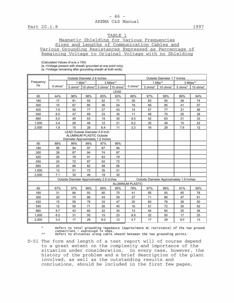
- 46 –AREMA C&S Manual
Part 20.1.8 1997
TABLE 1Magnetic Shielding for Various Frequencies
Sizes and Lengths of Communication Cables andVarious Grounding Resistances Expressed as Percentage ofRemaining Voltage to Original Voltage with no Shielding
(Calculated Values of er/ei x 100) (ei =Voltage present with sheath grounded at one point only) (er =Voltage remaining after grounding sheath at both ends)
Outside Diameter 2.6 Inches
Outside Diameter 1.7 Inches 1 Mile**
3 Miles**
1 Mile**
3 Miles**
Frequency Hz
0 ohms* 5 ohms*
10 ohms*
5 ohms*
10 ohms*
0 ohms* 5 ohms*
10 ohms*
5 ohms*
10 ohms*
LEAD 60
44%
96%
98%
85%
93%
66%
97%
99%
89%
94%
180
17
81
93
52
71
30
83
93
59
74 300
10
67
85
36
54
19
69
85
41
57
420
7.6
55
77
27
43
14
57
77
31
46 540
6.0
47
69
23
35
11
48
70
25
38
660
5.0
40
63
19
30
9.0
42
63
21
33 1,000
3.4
29
48
12
21
6.2
30
49
15
22
2,000
1.8
15
28
6.4
11
3.3
16
28
7.6
12
LEAD Outside Diameter 0.9 Inch ALUMINUM PLASTIC Outside
Diameter Approximately 1.2 Inches
60
88%
99%
99%
97%
99%
180
56
94
97
87
94
300
39
87
94
74
87
420
29
79
91
63
79
540
24
72
87
54
72
660
20
66
82
48
66
1,000
13
51
72
35
51
2,000
7.1
30
48
19
30
Outside Diameter Approximately 2.8 Inches
Outside Diameter Approximately 1.9 Inches
ALUMINUM PLASTIC
60
67%
97%
99%
89%
95%
78%
97%
99%
91%
95% 180
31
84
93
60
75
41
85
93
65
78
300
20
70
86
43
59
27
71
86
47
61 420
15
59
78
33
47
20
60
78
36
50
540
12
50
71
26
40
16
51
72
30
42 660
9.7
43
65
22
34
13
44
65
25
36
1,000
6.5
31
50
15
23
8.9
32
50
17
25 2,000
3.4
17
29
8.0
12
4.7
17
29
9.0
13
* Refers to total grounding impedance (Approximate dc resistance) of the two ground
connections - expressed in ohms. ** Refers to distances along cable sheath between the two grounding points.
D-51 The form and length of a test report will of course dependto a great extent on the complexity and importance of thesituation under consideration. In every case, however, thehistory of the problem and a brief description of the plantinvolved, as well as the outstanding results andconclusions, should be included in the first few pages,

- 47 –AREMA C&S Manual
1997 Part 20.1.8
with confirming data and details following, where necessary.A brief report that is well organized and easy to follow isbetter than a longer report which must be read throughcompletely before the problem becomes clear.
D-52 When the investigation includes many harmonic analyses ofwave shape and noise, it will be desirable to tabulate thedetailed results as attachments to the report and to includebrief summary tables in the body of the report along withthe discussion. These summaries might include only theoverall measured power system influence and noise, togetherwith the contributions of the important harmonic components.Comparative data taken under different test conditionsshould be included in the same tabulation wherever feasible.It is well to remember that a little time spent inorganizing and summarizing the material in the report mayeasily save considerable time for those reviewing thereport.
D-53 Maps and circuit schematics are usually helpful inindicating the general layout of the power and communicationfacilities under consideration. Wherever practicable, thepower and communication system layouts should be shown onthe same drawing. Also, use can often be made of graphicalmethods of presenting the test results. In particular, theresults of noise measurements on a number of exposedcommunication circuits under different power systemoperating conditions can be shown in a series of cumulativepercentage curves on the same background. A number ofdifferent methods of drawing such curves have beendeveloped. In the interest of uniformity it is suggestedthat the scheme shown in Figure 2018-8 be adopted wherepracticable.
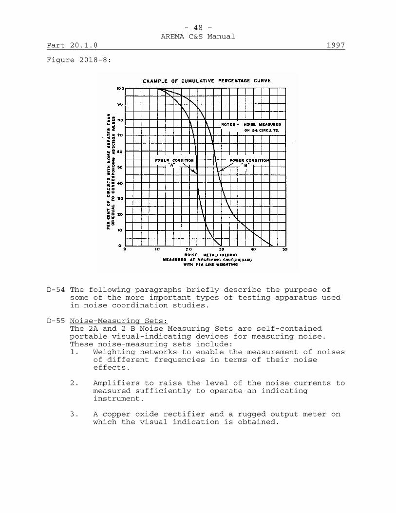
- 48 –AREMA C&S Manual
Part 20.1.8 1997
Figure 2018-8:
D-54 The following paragraphs briefly describe the purpose ofsome of the more important types of testing apparatus usedin noise coordination studies.
D-55 Noise-Measuring Sets:The 2A and 2 B Noise Measuring Sets are self-containedportable visual-indicating devices for measuring noise.These noise-measuring sets include:1. Weighting networks to enable the measurement of noises
of different frequencies in terms of their noiseeffects.
2. Amplifiers to raise the level of the noise currents tomeasured sufficiently to operate an indicatinginstrument.
3. A copper oxide rectifier and a rugged output meter onwhich the visual indication is obtained.
- 49 –AREMA C&S Manual
1997 Part 20.1.8
4. A graduated gain control permitting measurement of awide range of noise magnitudes.
5. Input coils and switching arrangements to facilitatethe various measurements.
6. Self-contained calibrating means.
7. Self-contained dry-cell battery supply.
8. A means for monitoring under all test conditions.
D-56 Harmonic Analyzers:The 10-A Noise Analyzer Attachment is an adjunct to the 2-Type Noise Measuring sets to provide a visual indicatingarrangement for measurements of individual harmoniccomponents of noise or power system influence in the rangefrom 180 to about 4,000 Hz (or higher under specialconditions.) The frequency selectivity, sensitivity,freedom from the effects of external fields, and otheroperating characteristics of the analyzer attachment –noisemeasuring set combination have been found satisfactory formost of the noise coordination problems which are apt to beencountered. It is impossible to overemphasize theimportance of harmonic analyses of power system influenceand noise in arriving at the solution to a noisecoordination problem.
D-57 Couplers for Power System Influence Measurements: The samenoise measuring set and analyzer which is used for noisetests may also be used for measurements and analyses ofpower system influence is auxiliary apparatus (mentioned inparagraphs D-58 and D-59) is used for connections to thepower system.
D-58 The current TIF coupler (per D-99127) consists chiefly of alow impedance (0.4 mh) retardation coil, together with a605-ohm resistance. These and the binding posts of thecoupler are so arranged as to facilitate connecting theretard coil in series with the secondary of a currenttransformer inserted in the power circuit under test, whilethe analyzer and/or noise measuring set in series with the605-ohm resistance is connected across the retard coil (viathe “To Set” binding posts) of the coupler. Because of itslow impedance (j0.15 ohm at 60 cycles) on the “To C.T.Sec.”side, this coupler has no effect on any metering or
- 50 –AREMA C&S Manual
Part 20.1.8 1997
relaying equipment that is normally connected to thesecondary of the same current transformer. The inductivereactance of the retard coil, in conjunction with the “line”weighing curve of the noise measuring set, provides theproper frequency weighting curve for measurements of ITproduct.
D-59 Similarly, the voltage TIF coupler (per D-00128) consistsessentially of a small condenser (0.01 mfd) in series with a605-ohm resistance. This coupler is so arranged that theanalyzer and/or noise measuring set can be connected acrossthe 605-ohm resistance. By this means, the device serves tocouple the input of the analyzer or noise measuring set tothe power voltage (secondary of service or potentialtransformer). On the “power voltage” side, the impedance ofthe coupler is controlled by the high impedance of the 0.01mfd condenser (265,000 ohms at 60 Hz) and therefore has noeffect on any metering or relaying equipment that might beconnected to the same transformer secondary. In this casethe capacitive reactance of the condenser and the “line”weighting curve of the noise measuring set provide theproper frequency weighting for measurement of the KvTproduct.
D-60 Current and Potential Transformers: Measurements of powersystem influence and supplementary harmonic analyses may bemade on the secondaries of current and potentialtransformers normally employed for metering and relaying or,in special cases, on specially installed transformers. Inthe latter case, the current transformers may be connecteddirectly in series with the circuit under test or may be ofthe clamp or “split core” type.
D-61 Miscellaneous Equipment: In addition to the apparatusalready mentioned, a variety of other testing equipment andspecial terminating arrangements may be required in noisecoordination work.

AMERICAN RAILWAY ENGINEERING AND MAINTENANCE OF WAY ASSOCIATION
COMMUNICATIONS & SIGNALS MANUAL
Section 21 – Data Transmission
2002

This page intentionally left blank
AREMA® C&S Manual 2002 (Includes 2002 Revisions) Volume 5 Index SECTION 21 - DATA TRANSMISSION Part C Type & Subject Pages Status
______________________________________________________________- 1 -
Note: C = Committee responsible for Manual Part.
21.1.1 35-3 Recommended Functional/ Operating Guidelines for Telephone Transmission 19 Extended 2001 21.1.2 35-3 Recommended Functional/ Operating Guidelines for Analog Data Transmission Over Voice Channels 12 Extended 2001

This page intentionally left blank
- 1 –AREMA C&S Manual
2001 Part 21.1.1
Recommended Functional/Operating Guidelines forTelephone TransmissionExtended 2001 (19 Pages)
A. General Requirements1. Telephone System: The primary function of a telephone
system is to provide for the transmission ofinformation (including speech, data, graphics, video,etc.) with sufficient faithfulness, received level andfreedom from extraneous noises to be readily usable,and to provide a satisfactory means of signaling. Toattain this objective, the equipment and linefacilities must be suitably designed, installed andmaintained. The actual results depend to aconsiderable extent on how the system is used, but asthe use is largely beyond the control of thecommunications engineer the following sections dealonly with design and maintenance.
2. Telephone Transmitter: The telephone transmitter is ameans for translating acoustic vibrations intoelectrical current variations. A transmitter widelyused accomplishes this by varying its resistance inaccordance with variations of the sound pressure.That part of the transmitter whose resistance issubject to variation is the carbon button and consistsof a small sealed chamber partly filled with granularcarbon through which direct current passes when thetelephone set is used. When the transmitter diaphragmvibrates in response to speech, the resistance of thecarbon button is varied which in turn varies thedirect current. These latter variations are in effectalternating current and constitute the speech currentstransmitted over telephone circuits. The telephonetransmitter introduces some frequency distortionbecause its electrical output is not uniform over theentire speech range for a given input energy. Thetransmitter also introduces some frequencies otherthan those impinging upon the transmitter. Thislatter type of distortion is noticeable only when thetransmitter is overloaded due to too high talkingvolumes. Offsetting these disadvantages is the factthat the carbon transmitter is a very effectiveamplifier, that is, the electrical energy in theoutput is many times that of the acustic energyimpinging upon the transmitter diaphragm.
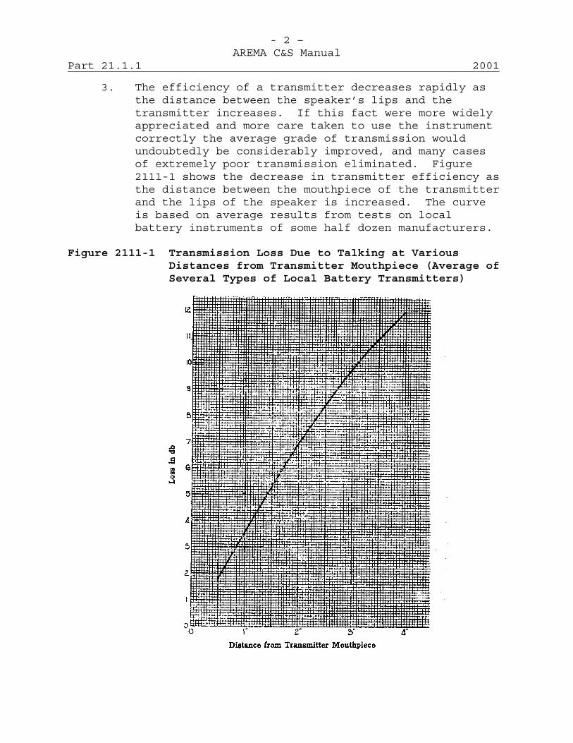
- 2 –AREMA C&S Manual
Part 21.1.1 2001
3. The efficiency of a transmitter decreases rapidly asthe distance between the speaker’s lips and thetransmitter increases. If this fact were more widelyappreciated and more care taken to use the instrumentcorrectly the average grade of transmission wouldundoubtedly be considerably improved, and many casesof extremely poor transmission eliminated. Figure2111-1 shows the decrease in transmitter efficiency asthe distance between the mouthpiece of the transmitterand the lips of the speaker is increased. The curveis based on average results from tests on localbattery instruments of some half dozen manufacturers.
Figure 2111-1 Transmission Loss Due to Talking at VariousDistances from Transmitter Mouthpiece (Average ofSeveral Types of Local Battery Transmitters)
- 3 –AREMA C&S Manual
2001 Part 21.1.1
4. Telephone Receiver: The function of the receiver isthe opposite of the transmitter since it is actuatedby the alternating electric currents and deliversacoustic waves. This is accomplished by the variationin pull on the diaphragm by the electromagnet that isenergized by the line current. As in the case of thetransmitter, the quality characteristics of thereceiver are dependent upon both its electrical andits mechanical performance.
5. Telephone Sets: A telephone set is a combination ofreceiver and transmitter and is associated with asubset which contains an induction coil, usually aringer, and in some cases, other equipment. Thebattery supply for the transmitter may be from localbatteries or from a common battery source. In thelatter case, the transmitter current flows over thesame conductors as used for speech transmission.
6. Common-Battery Sets: "Anti-sidetone" circuits are nowstandard for common-battery telephone sets. In theolder circuits high side-tone in the speaker's earoften caused the user to unconsciously lower hisvoice. Furthermore, room noises were amplified in hisear when he was listening. Both of these conditions,in effect, degrade transmission. Anti-sidetone setsemploy a balancing arrangement that eliminates thespeaker's voice from his own receiver. The degree ofbalance obtainable varies with frequency and withimpedance of the connected line. The balance cannot,therefore, be perfect but it is generally good enoughto provide performance quite superior to the olderside-tone sets.
7. Local-Battery Sets: These are two general types oflocal-battery sets. One type uses a push button (orfoot switch) to cut the transmitter into the circuitonly when the user is actually speaking. Sets of thistype have inherently good transmission efficiency.They are especially useful where more than two phonesare bridged on a line simultaneously because they havea low bridging loss and because transmitter backgroundnoise is eliminated from all but the one set beingused by the speaker at any given instance. Sets ofthis type are almost universally used on dispatchingcircuits.
- 4 –AREMA C&S Manual
Part 21.1.1 2001
8. The other type of local-battery set employs atransmitter circuit that is continuously closed whenthe set is in the "off-hook" condition. Such sets arequite satisfactory on lines normally used by only twopeople at any given time. The use of this set issimpler for those not accustomed to "push-to-talk"sets.
9. Telephone Circuits: The circuits between twotelephone sets may be direct or may be switched at oneor more points. The circuits may be physical or theymay be derived. In any case it is necessary thatspeech be transmitted with adequate volume, sufficientfaithfulness, and relative freedom from noise andcrosstalk. In many instances these requirements canbe met only by giving very careful consideration tothe characteristics of the circuit facilities.Attenuation and noise levels are of paramountimportance. Flat attenuation frequencycharacteristics and wide bandwidth (250-3,000 cycles)are desirable but must frequently be sacrificed whereincreased circuit capacity of a line is a requirement.
B. Types of Railroad Circuits1. The following classes of circuits (based primarily on
usage rather than design) are commonly found inrailroad service:a. Trunk circuits.
b. Train dispatching circuits.
c. Message circuits.
d. PAX circuits.
e. Yard circuits.
f. PBX extensions.
g. Block circuits.
h. Party line circuits.
2. Trunk Circuits: A trunk circuit interconnects twoswitchboards. The switchboards may be miles apart andnot infrequently are separated by hundreds of miles.

- 5 –AREMA C&S Manual
2001 Part 21.1.1
Short trunks of a dozen miles or less are usuallyphysical circuits. Longer trunks are generallyderived circuits. A large, and constantly increasing,proportion of long trunk circuits are carrier derived.Signaling is either ring-down or dial depending onterminal use.
3. Train Dispatching Circuits: Dispatching circuits arenormally physical, although sections of carrier arenot uncommon when the dispatcher is remote from thecontrolled territory. The dispatcher's circuit is apush-to-talk, local-battery party line. Selectivesignaling, employing individual impulse followingselectors, is used outward from the dispatcher'soffice. The dispatcher is generally provided with anamplifier-loudspeaker set which eliminates any needfor inward signaling.
4. Message Circuits: These circuits are provided tointerconnect all way stations on a district ordivision, and generally terminate in a railroad ownedor leased private branch exchange switchboard.Signaling toward the switchboard is 20-Hz ring-down.Signaling outward from the switchboard is, byselectors, similar to those used on dispatchercircuits, by 20-Hz code ringing, or by a combinationof both. Message circuits are almost universally ofthe local-battery type and usually use a commontelephone set switchable between the dispatcher andmessage lines.
5. Private Automatic Exchange (PAX) Circuits: Dialtelephones are extensively used by railroads. Suchsystems do not differ essentially from those commonlyused by other industries.
6. Yard Circuits: Where PAX service is not available,yard communication is usually provided by a circuitconnecting all principal points in the yard. Itusually is of the local-battery, code-ringing type andgenerally does not terminate in a switchboard.
7. Private Branch (PBX) Extensions: Wherever PBX serviceis provided, local phones are served by extension linesfrom the switchboard. These lines are common battery.
- 6 –AREMA C&S Manual
Part 21.1.1 2001
They may be manually switched or may be a combinationof manual and dial.
8. Block Circuits: Block circuits were provided toconnect adjacent block stations, but sometimes wereextended to connect several stations. Generally, theywere local-battery, code-ringing, and do not connectto a switchboard. Block station eliminations have allbut obsoleted this type circuit.
9. Party Line Circuits: Some use is made of party lineservice on lightly loaded circuits extending from asingle PBX switchboard to outlying points, or in someinstances on semi-trunk circuits between two distantPBX switchboard locations. When such service is usedthe intermediate telephones (or PBX switchboard) areconnected to the circuits on a bridging basis. Codedmagneto ringing is generally used for signalingpurposes.
10. Miscellaneous Circuits: The list of circuits givenunder Paragraph B-1 is not exhaustive. Many othertypes of circuits are used in railroad service.Paging loudspeaker, talk-back loudspeaker, and officeinter-communicating sets are examples of the manyarrangements available.
C. Transmission Losses1. Some of the electrical power input into a circuit is
dissipated in the circuit due to line attenuation,reflection and equipment losses. These losses in thepower transmitted over a circuit are termedtransmission losses. Transmission losses are commonlyexpressed in terms of the attenuation or power ratiobetween the input and output of a circuit. The unitis the decibel (abbreviated "db") that is alogarithmic expression of the power ratio. The lossexpressed in decibels in a particular case is
P110 log ____ where P1 is the input power and P2 the
P2output or received power. Where the impedances are equal,
I1 E1db equals 20 log___ or 20 log where I1
I2 E2
- 7 –AREMA C&S Manual
2001 Part 21.1.1
and E1 are the input and I2 and E2 are the output currentand voltage.
2. The use of a logarithmic unit such as the db permitsthe direct addition of the losses in different partsof a circuit, or of the gains due to repeaters.
3. Line Loss: Line loss, or attenuation, reduces themagnitude of the received power. The followingfactors affect line loss.a. Resistance: This is influenced largely by the
size, material, and temperature of the lineconductors. The unit of resistance is the ohm.
b. Leakage or Leakage Conductance: This is theshunt loss between the two conductors of thecircuit. It is measured in mhos, and at lowfrequencies is practically the reciprocal of theline insulation resistance. Leakage, in openwire, depends on the number, type and conditionof the insulators, foreign contacts such astrees, and upon weather conditions. At highfrequencies, other factors are involved.
c. Inductance: The series inductance of a circuitis the self-inductance of each conductor plus themutual inductance between the individualconductors of the pair. The magnitude of theseries inductance is dependent upon the material,size and spacing of the wires and the surroundingconductors. At a given frequency, the greaterthe separation of the conductors, the larger theinductance. The effect of inductance isdependent upon the imposed frequency. The unitof inductance is the henry.
d. Capacitance: The shunt electrostatic capacitanceof a circuit is the electrical capacitancebetween the two conductors of the pair includingthe effect of capacitance to earth. Themagnitude of the shunt capacitance is dependenton the size, separation and dielectric materialbetween the conductors, as well as the presenceof surrounding conductors. With a givenfrequency and dielectric constant, the closer theconductors, the greater the capacitance. The
- 8 –AREMA C&S Manual
Part 21.1.1 2001
effect of capacitance is dependent upon theimposed frequency. The unit of capacitance isthe farad.
4. Characteristic Impedance: This is the impedancelooking into one end of a infinitely long uniform line.By definition, it is also the impedance of a uniformline of any length terminated in its characteristicimpedance. It is dependent on the frequency and thefour factors above noted in connection with line loss.It is measured in ohms.
5. Reflection and Return Losses: When alternatingcurrents traveling along a circuit encounter animpedance irregularity; i.e., pass from a circuit ofone impedance to one of another impedance, a portionof the current or voltage is reflected and travelsback toward the sending end. This loss intransmission through the irregularity is known as thereflection loss and in computing the overall loss in acircuit or connection these reflection losses areadded to the attenuation losses. Expressed in termsof the line impedances looking in the two directionsat the irregularity Z1 and Z2, the power reflectionloss in db
Z1 + Z2equals 20 log _______
2Z1 Z2
6. The ratio of the reflected current to the currentstriking the irregularity is known as the return loss.The return loss is of principal interest in its effecton repeater balances and may be referred to therepeater by adding twice the attenuation loss betweenthe irregularity and the repeater. This is then knownas the "singing" point irregularity. The return lossin db equals
Zn + ZL20 log where Zn is impedance of the network
Zn - ZLand ZL is impedance of the line.
7. Insertion Loss: The complete effect of theintroduction of a piece of equipment or line in a
- 9 –AREMA C&S Manual
2001 Part 21.1.1
circuit is frequently considered in terms of itsinsertion loss. The insertion loss obviously includesboth the reflection effects and the losses or gains inthe device or line itself. The insertion loss isdefined as a loss expressed in decibels of the ratiobetween the power received with the device or line notin the circuit and that received with the device orline inserted in the circuit. It should be noted thatthe result is frequently an insertion gain,particularly where a repeating coil of the properratio is inserted at a point of the junction of twolines of unequal impedance and existing reflectioneffects are reduced.
D. Distortion1. Attenuation-Frequency Distortion:
Attenuation-frequency distortion may be defined as thedistortion or modification of voice signals passingthrough a unit of apparatus or circuit of such acharacter that the attenuation of a signal is not thesame at all frequencies. Such distortion results inunequal losses to the various frequency componentsdesired for speech transmission and may seriouslyaffect the intelligibility of the received signal.
2. Frequency Distortion may be introduced into a circuitby station equipment, repeating coils and otherapparatus, such as repeaters, if they do not have asatisfactory attenuation-frequency characteristic.Another source of frequency distortion is the lineitself. Non-loaded open wire circuits arecomparatively free from this form of distortion, butthis is not true of cable facilities. Loaded cablefacilities have a comparatively flat transmissionfrequency characteristic within the band for which theloading system is designed.
3. Non-Linear Distortion: Non-linear distortion is themodification of signals passing through a unit ofapparatus or a circuit in a manner such that theoutput of the unit or circuit is not proportional tothe input. In other words, for a given change ininput energy, where this type of distortion occurs,there will not be a corresponding and proportionalchange in the output energy. This effect may resultin apparent changes in the transmission loss or gain

- 10 –AREMA C&S Manual
Part 21.1.1 2001
of the circuit and results in the generation ofharmonics and other undesired frequencies.
4. Non-linear distortion may take place in telephonetransmitters or receivers where the conversion frommechanical to electrical signals, or vice versa, isnot equally efficient for all energy values.
5. Non-linear distortion may take place in repeatingcoils where these coils are operated at higher currentlevels than they are designed for or where, throughabnormal use, these coils have become magnetized. Theresult is the generation of harmonics and themodulation of normal line signals, one upon the other,to produce undesired products of modulation.
6. Non-linear distortion may occur in repeater equipmentusing analog amplifying circuits, producing distortionof the signal or extraneous noise when operated beyondrated input values.
7. Delay Distortion: Delay distortion is themodification of signals passing through a circuitunder conditions such that certain frequencies orgroups of frequencies are delayed and arrive at thereceiving end of the circuit after the remainder ofthe frequencies have arrived. This results in a phaserelation between the frequency components of thereceived signal different from the relation in theoriginal or transmitted signal. Delay distortion willseldom be apparent in railway voice telephonecircuits. It is present in each unit of equipment andin each section of line, but is so small as to benegligible. When many of these units are connected intandem to provide a circuit, the distortion may besufficiently great to require attention if the circuitis used for purposes other than voice.
E. Interference1. General: Although a system may be capable of
transmitting speech with sufficient volume and withgood quality, the presence of disturbing noises maydetract from the intelligibility of the speechreceived and in some cases may make the circuitunsatisfactory. A small amount of noise may in effectbe equivalent to an appreciable increase in

- 11 –AREMA C&S Manual
2001 Part 21.1.1
transmission loss. Disturbing noises may be due toinductive disturbances, cross talk and other causes.
2. Inductive Interference: Telephone noises can becaused by paralleling power circuits. Such noises mayresult from inadequate or uncorrelated transpositionsystems or from transposition errors. The effects ofinductive disturbances are increased by lineunbalance. Corresponding electrical quantities forthe two sides of the circuit should be substantiallyequal at all points along the circuit; that is, thereshould be electrical symmetry of the two sides of thecircuit. Unbalances may be due to fuses or heat coilsof unequal resistance in the two sides of the line,high resistance in the line due to sleeve or otherline joints, loose connections in equipment or wiring,unequal leakage in the two sides of the circuit,partial grounds in line or protectors, different gagesof wire in the two sides of the line, or other causes.
3. Crosstalk: Under this heading is classed thetransference of voice frequencies from one circuit toanother, which may be due to several causes, amongwhich are induction between physical circuits or partsthereof, unbalance between the two sides of a phantomgroup, resistance and capacitance unbalances incapablecircuits and a variety of defects in office equipmentand wiring. Crosstalk may be caused by inadequatetranspositions or by transposition errors in open wirecircuits or by induction between improperly shieldedrepeating coils and relays. Excessive capacitanceunbalances may be due to improper splicing of cable.High impedance battery leads may be responsible for aconsiderable amount of crosstalk.
4. Other Noises: Besides disturbing noises traceabledirectly to inductive disturbances and crosstalk, roomnoises are often a source of disturbance. Room noisemay be detrimental to intelligible transmission inseveral ways; it may interfere directly, it may bepicked up by the transmitter and appear as sidetonenoise in the receiver and thus affect transmission, orit may be transmitted to the other end of the line andinterfere with received speech. Of the methods bywhich room noises may cause impairment oftransmission, that of sidetone noise is the most

- 12 –AREMA C&S Manual
Part 21.1.1 2001
detrimental and may be minimized by the use oftransmitter cutouts and anti-sidetone sets.
F. Reference Standards1. Volume Reference Standard: It is the practice in
communication work to measure the speech volume levelon a circuit by means of a device called a volumeindicator. This instrument has clearly definedballistic characteristic and pointer action thatfollows the variation in the speech wave in adetermined suitable manner.
2. The Standard Volume Indicator is calibrated to give asteady state reading of zero when a 1,000 Hz signal ofone milliwatt is being dissipated in a 600-ohmresistance across which the instrument is bridged.Readings made with a volume indicator of this type andcalibrated in this way are recorded as "+ X vu," whereX is the number of db by which the speech volume leveldiffers from the reference level of this meter.
3. Transmission Testing Standards: In makingtransmission tests on telephone circuits it is theusual procedure to transmit a power of one milliwatt(0 dbm) into the line at the sending end. The powerreceived at the other end is measured and itsrelationship to one milliwatt, expresses thetransmission gain or loss of the circuit. Both endsof the circuit must be terminated in 600 ohmsimpedance or such other impedance as specified.
4. Noise Reference Standard: A circuit noise metermeasures noise in terms of the number of db by whichthe noise reading exceeds a certain referencestandard. The communications industry has in the pastused as the reference power level for noisemeasurements 10-12 watt, or 90 db below 1 milliwatt at1,000 Hz per second. Measurements made in decibelsabove this reference level using a 144-weightingnetwork were called dbRN or decibels above referencelevel. A practice has been to use F1A weighting basedon the more sensitive F1A handset, and to use -85 dbmas the reference level. Measurements made with theF1A weighting network are designated as "dba" ordecibels adjusted to differentiate between the old andnew standard. With the 500-type set, a new weighting

- 13 –AREMA C&S Manual
2001 Part 21.1.1
characteristic was found desirable. A new noise meterhas reverted to the use of the original referencelevel of 10-12 watt, or 90 db below 1 milliwatt at1,000 cycles. However, due to the difference in F1Aweighting and the new 500 set, or C-message weightingthe measurement made with the set should be designatedas "dbRn C-Message" for purposes of differentiation.
5. Standard Crosstalk Unit: The crosstalk meter incommon use is calibrated in terms of db and expressesthe db loss between the transmitted power on thedisturbing circuit and the received power on thedisturbed circuit. These meters are also calibratedin terms of crosstalk units. These units express inone-millionths the ratio of the received current onthe disturbed circuit to the transmitted current onthe disturbing circuit. The crosstalk unit isabbreviated "dbx.". Reference coupling is that whichproduce 0 dba in the disturbed circuit when a testtone of 90 dba is impressed on the disturbing circuit.Both values of dba are for the same weighting.
6. Reference Power Unit: The most common reference powerused in communications work is the milliwatt. Aconvenient method of indicating an amount of power isto express it as being so many db above a referencepower of one milliwatt. Because of its common usage,decibels above or below one milliwatt are usuallyabbreviated plus or minus dbm.
G. Line Facilities and Equipment1. General: There are several aspects with regard to
line facilities and equipment which involvetransmission considerations of a type which it wouldbe desirable to review in this section. This appliesparticularly to the use of loading and repeaters forimproving the transmission performance of existingcircuits and in designing new ones, and to theapplication of carrier systems for deriving newcircuits.
2. Loading: Loading coils are inductances that areinserted in telephone circuits at regular intervals tooffset or counteract the effect of capacitance betweenwires. While loading was formerly applied to openwire circuits, other methods of reducing attenuation
- 14 –AREMA C&S Manual
Part 21.1.1 2001
such as the use of repeaters have proven moreeconomical and more reliable and at present theapplication of loading is restricted to cablefacilities and long twisted pair runs. The purpose ofloading is to reduce attenuation and to provide animproved transmission frequency characteristic. Inaddition, it is often desirable to load entrance andintermediate cables on open wire routes in order tomake the impedances of the cable facilitiessubstantially equal to the open wire, as well asreduce the attenuation and the variation ofattenuation with frequency. This, of course, reducesline irregularities and permits the operation ofrepeaters at higher gains than might otherwise bepossible.
3. There are several loading systems commonly in use.Those systems that make use of the lower inductancecoils and shorter spacings provide the higher cut-offfrequencies. It is generally desirable to selectsystems that provide nominal cut-off frequencies of atleast 2,900 Hz. For the longer cable circuits orcable circuits which may be used as links in longbuilt-up connections it is particularly important tomake use of the higher cut-off types of loading, suchas H-44-25, H-88-50, B-88-50, etc., in order to avoidobjectionable echo and singing reactions.
4. In the case of toll entrance and intermediate cablesin open-wire lines, the selection of loading usuallyinvolves a review of the several possible loadinglayouts that might be used. A number of systems havebeen worked out making use of full weight andfractional weight coils in combination for differentlengths of cables.
5. Cable facilities loaded for voice frequency systemswill not satisfactorily transmit carrier frequencies.Where carrier systems are involved and loading isnecessary, carrier-loading systems should, therefore,be used. These carrier-loading systems not onlyreduce attenuation but will also largely eliminatereflection losses at junctions with open wire. Whencable pairs connect with open wire carrying both voicefrequency and carrier it is sometimes necessary toseparate the frequencies by means of filters and
- 15 –AREMA C&S Manual
2001 Part 21.1.1
transmit the voice frequency over one pair and thecarrier frequency over another. For best results eachpair should be loaded for the frequencies that it isto pass.
6. Voice-Frequency Repeaters: Telephone repeaters arebasically amplifiers and are employed to overcomeexcessive attenuation losses. Four-wire repeaters arerelatively simple and are capable of high gain.Two-wire repeaters require hybrid-balancingarrangements that inherently make them much lessstable than four-wire repeaters. Two-wire repeatersare easily unbalanced by changes in line impedance.If adjusted to produce high gains they are easilythrown into a feed-back, or "sing," condition.
7. Depending upon their application, voice-frequencyrepeaters fall into two classifications: (1) Terminaland (2) Through-line.
8. Terminal repeaters are often favored because of easiertesting and maintenance of facilities at terminalpoints, but through-line repeaters generally yieldbetter transmission gains.
9. "Negative Impedance" Repeaters are finding some use onrailroad cable circuits. They are designed to producea phase shift which feeds more energy into the linethan is drawn from it.
H. Carrier Telephone1. Carrier: Carrier systems provide a means of
communication through the use of frequencies abovethose of the normal voice circuit range. This isaccomplished by apparatus at the circuit terminalswhich translate the voice frequencies received intocarrier frequencies whereas at the opposite end thecarrier frequencies are translated back into voicefrequencies. The first of these operations is calledmodulation and the second demodulation. In theopposite direction of transmission the same thing isdone but the carrier frequency band used on the lineis different. For example, the band from 4,000 to6,800 Hz may be used for transmission from the west toeast direction and the band from 7,200 to 10,000 Hzused for the opposite direction of transmission.
- 16 –AREMA C&S Manual
Part 21.1.1 2001
Filters in the carrier equipments prevent the carrierchannels and voice circuit from interfering with oneanother.
2. Basic Types: There are several methods of securingderived circuits by the use of carrier frequencies butonly two are in common use:a. Single sideband, amplitude modulation.
b. Frequency modulation.
Single sideband amplitude modulated carriers arealmost universally employed in trunk circuits. Thisis largely because they are efficient users ofbandwidth and therefore permit a maximum number ofchannels in a given spectrum space.
3. Low-Frequency and High-Frequency Carriers:Single-channel carriers usually occupy afrequency-range of from 4,000 to 10,000 Hz.Three-channel carriers generally extend upward toabout 35,000 Hz. High-frequency carriers extend from40,000 to about 150,000 Hz and normally provide 12channels. There are other carrier systems having asmany as 600 channels but they are designed forco-axial cables or microwave radio.
4. Attenuation of Carrier Frequencies: When planningcarrier installations consideration must be given tothe greater attenuation of carrier compared to voicefrequencies. Although this increase is not nearlyproportional to frequency, it is an appreciablefactor. On 0.104 dry, open copper wire, for example,the attenuation at 100,000 Hz is approximately fourtimes the db loss at 1,000 Hz. This disadvantage isat least partly offset by the fact that carrierrepeaters are generally much more effective thanvoice-frequency repeaters and provide much highergains. The explanation of this is that carrierrepeaters are, in effect, four-wire repeaters.Actually, transmission in both directions may takeplace over the same pair of wires, but the use ofseparate frequencies for the two directions, insolatedform each other by appropriate filters, provides verynearly the equivalent of a four-wire circuit.

- 17 –AREMA C&S Manual
2001 Part 21.1.1
5. Carrier Regulation: Carrier attenuation on cablepairs is subject to variation with temperature.Attenuation on open-wire pairs is subject not only totemperature effects but also to the greater effects ofwet weather, snow, and ice. A 100-mile carriercircuit, for example, having a dry-weather attenuationof 20 db may have losses of as much as 100 db undersevere icing conditions. Such a circuit wouldobviously become completely unworkable unlessincreased gain is provided to compensate for thelosses. All long-haul carriers are provided withautomatic gain control. This feature makes possiblethe operation of high-quality circuits with manyrepeater sections. Circuits 2,000 and more miles inlength are not uncommon.
I. T-Carrier Systems1. CARRIER: Describes a digital communications facility
with a 1.544 Mbps bandwidth that can be used fordigitized voice, data or image transmission. The1.544 Mbps standard is used in both North America andJapan; the rest of the world implements E-1 at 2.048Mbps. T-1 service is available from virtually everylong distance carrier, as well as satellite carriers.Although it started strictly in the province oftelephone companies, it is now available to end-users.Numerous multiplexer vendors offer equipment so thatrailroads can utilize it on their own transmissionlines, including copper, coax and fiber-optic
2. CHANNELS: T-1 "pipes" carry the equivalent oftwenty-four 64 Kbps voice circuits, or othercombination of voice, data or video within their 1.544Mbps bandwidth. For pure data transmission, a T-1line can handle more than 24 circuits, since data maybe at other speeds, as 1.2, 2.4, 4.8, 9.6, 19.2, 56Kbps, 64 Kbps, N x 64 Kbps.
3. MODULATION TECHNIQUE: In its basic implementation forvoice communications, a T-1 channel bank samplesanalog signals from each of up to 24 channelsconnected to it. Using Pulse Code Modulation (PCM)techniques an analog signal is sampled 8000 times persecond, each sample being represented by an 8-bitcode. This results in a digitized voice signalrequiring 64 Kbps of bandwidth for each individual
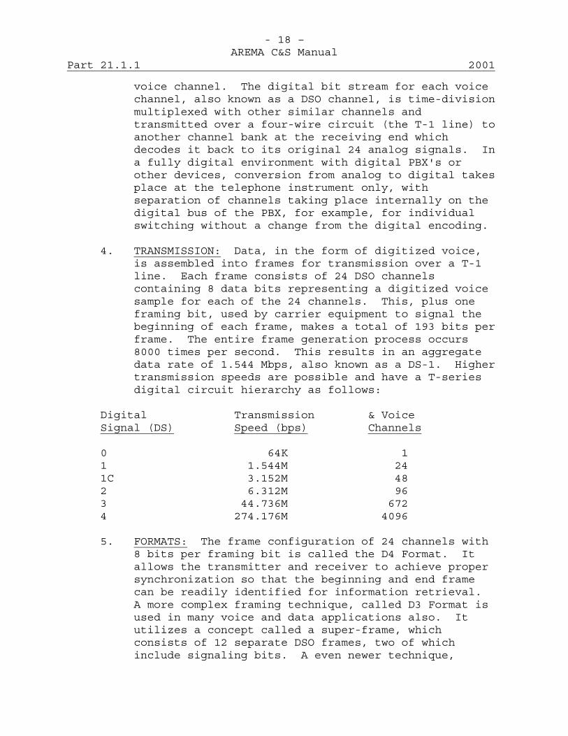
- 18 –AREMA C&S Manual
Part 21.1.1 2001
voice channel. The digital bit stream for each voicechannel, also known as a DSO channel, is time-divisionmultiplexed with other similar channels andtransmitted over a four-wire circuit (the T-1 line) toanother channel bank at the receiving end whichdecodes it back to its original 24 analog signals. Ina fully digital environment with digital PBX's orother devices, conversion from analog to digital takesplace at the telephone instrument only, withseparation of channels taking place internally on thedigital bus of the PBX, for example, for individualswitching without a change from the digital encoding.
4. TRANSMISSION: Data, in the form of digitized voice,is assembled into frames for transmission over a T-1line. Each frame consists of 24 DSO channelscontaining 8 data bits representing a digitized voicesample for each of the 24 channels. This, plus oneframing bit, used by carrier equipment to signal thebeginning of each frame, makes a total of 193 bits perframe. The entire frame generation process occurs8000 times per second. This results in an aggregatedata rate of 1.544 Mbps, also known as a DS-1. Highertransmission speeds are possible and have a T-seriesdigital circuit hierarchy as follows:
Digital Transmission & VoiceSignal (DS) Speed (bps) Channels
0 64K 11 1.544M 241C 3.152M 482 6.312M 963 44.736M 6724 274.176M 4096
5. FORMATS: The frame configuration of 24 channels with8 bits per framing bit is called the D4 Format. Itallows the transmitter and receiver to achieve propersynchronization so that the beginning and end framecan be readily identified for information retrieval.A more complex framing technique, called D3 Format isused in many voice and data applications also. Itutilizes a concept called a super-frame, whichconsists of 12 separate DSO frames, two of whichinclude signaling bits. A even newer technique,
- 19 –AREMA C&S Manual
2001 Part 21.1.1
called Extended Super-frame Format (ESF), adds aFacility Data Link (4 Kbps) and Cyclic RedundancyCheck (2 Kbps) to a smaller framing sequence of 2Kbps. The result is continued use of the one bit forevery 8000 samples (8 Kbps) concept, but provides adata channel between ends without interrupting asession in progress and the CRC indication oftransmission quality over the circuit. Thisinformation can be polled by Network Management toproactively monitor line performance.
6. TIMING: Since T-1 is a synchronous type oftransmission, it must have timing information encodedbetween sending and receiving devices, plus all signalrepeaters in between. In T-1, timing information issent as part of the digital pulse stream. Thebeginning pulse of each frame is called the S, orframing, pulse and is used to synchronize terminaldevices. The least significant pulse, or 8th bit, isoften used for timing and signaling. Thus smallerrors are created. Voice traffic is generallyunaffected by these errors but data speeds are limitedto 56 Kbps in this system, since data does requireerror-free transmission. However, ISDN standards,which is based on T-1 specifications, eliminates eventhis limitation by providing for separate signalingchannels on each connection.
7. High bit rate Digital Subscriber Link (HDSL) providesDS-1 transmission thru existing metallic plant withextended range unaffected by bridge taps.

This page intentionally left blank
- 1 – AREMA C&S Manual
2001 Part 21.1.2
Recommended Functional/Operating Guidelines for Analog Data Transmission Over Voice Channels
Extended 2001 (12 Pages) A. Scope
The transmission of data over channels that have been designed primarily for voice operation presents some new problems. Certain transmission parameters that are of small concern in voice transmission must be carefully considered in order to assure satisfactory data transmission performance. The following paragraphs describe these parameters and the mitigation of some of the possible transmission impairments.
B. General Considerations
1. In voice communication the talker and listener usually have a high degree of tolerance to transmission impairments. For one thing, redundancy in speech often allows the listener to supply syllables or even words missed or garbled because of noise, excess loss or other transmission difficulties. Also, people will adjust themselves (within limits) to problems in transmission by talking louder, listening more closely or asking for repeats.
2. Data transmission is more exacting than voice
transmission for a number of reasons. First and foremost the data sets are really electronic devices that do not exhibit human characteristics. The sets cannot adjust themselves to transmission variations except within very narrow limits. Further, not only are they very sensitive to the same transmission impairments as voice but they are also sensitive to other transmission parameters which have little effect on voice.
C. Transmission Considerations
1. Primary transmission characteristics of voice channels that can affect data transmission are:
Over-all Attenuation Attenuation-Frequency Characteristics Return Loss and Echo Steady Background (White) Noise Impulse Noise Delay-Frequency Characteristics Carrier Frequency Error

- 2 – AREMA C&S Manual
Part 21.1.2 2001
Of these, only the first four usually cause serious difficulties in voice transmission. The same four items are even more important in data transmission, because degradations not serious enough to prevent voice communications may make data transmission virtually impossible. The last three items are of minor importance in voice transmission but are very important to the transmission of data signals.
2. Transmission Levels: The maximum transmit level of
data sets is limited by both crosstalk considerations and the maximum level at which the data signals may be applied to a carrier channel. The data carrier level should be set at a level -13 dbm0 (below ref./test tone level) for measurement point. When more than one tone is involved in the data signal the above transmit levels represent the total rms power of all tones transmitted simultaneously.
3. Over-all Loss: The maximum over-all loss allowable
between data sets depends upon the sensitivity of the set and varies with the type of set and operating frequencies. Generally, the maximum permissible loss ranges from 30 to 45 db. Exact figures can be obtained by subtracting the maximum transmit level from the minimum receive level. In determining this value the highest frequency used by the data signal should be considered.
4. Data transmission systems are susceptible to over-all
loss changes due to level variations that may be encountered on a channel. The effect of level variations on data transmission is dependent upon a number of factors, including type of modulation and type of automatic gain control used in the data sets, magnitude of level changes, and the frequency with which level changes occur. Effects of level changes on data sets are usually most serious when the changes result in higher loss and the data sets are operating near their minimum receive levels. Typical of level variations that may be encountered are:
a. Changes due to temperature, daily as well as
seasonal, component aging, etc.
- 3 – AREMA C&S Manual
2001 Part 21.1.2
b. Abrupt changes due to microwave switching,
microwave fading where protection channels are not available, regulation action, equipment irregularities, etc.
c. Slow level changes up and down at a cyclic rate of
several seconds or more.
Level variations can be kept to a minimum by the application of proper engineering and maintenance practices.
5. Loss-Frequency Characteristics: The loss-frequency
characteristic (sometimes referred to as the transmission-frequency characteristic) is very important to good data transmission. A loss-frequency curve can be used to determine both attenuation distortion (sometimes called frequency distortion) and bandwidth. Attenuation distortion is usually expressed as so many db slope across the transmitted band. For optimum data transmission this slope should be essentially 0 db, in other words, the loss-frequency curve should be essentially flat in the transmitted band. In the practical case data sets are designed to tolerate some attenuation distortion. With those data sets using speeds under 200 bits per second slope is not a serious problem because of the limited bandwidth. Some of the higher speed data sets (1200-2400 bits per second range) have compromise loss-frequency equalizers that increase their tolerance to slope. Slope tolerances for the various types of data sets range from about 3 to 10 db in a band of 1,000 to 2,300 Hz. Most cases of excessive slope on channels can be taken care of by the application of attenuation-frequency equalizers.
6. The loss-frequency characteristic of a channel can be
used to define its bandwidth. Some data sets involve frequencies as low as 600 Hz and as high as 2,700 Hz. Modern transmission facilities provide sufficient bandwidth for such as some of the older type carrier systems and heavy loaded cable systems such as the H172-63 system may prohibit the use of such data sets.

- 4 – AREMA C&S Manual
Part 21.1.2 2001
7. Return Loss and Echo: In voice transmission, talker
echo is controlling. With properly designed data sets talker echo is not particularly important because the set cannot send and receive on the same frequency at the same time. It is necessary to delay the start of data reception until talker echoes have diminished but this is accomplished in the design of the data set. Listener echo, on the other had, is very important in data transmission because the receiving data set will interpret data received through the echo path as interference. This happens because listener echoes usually affect subsequent transmitted pulses at bit speeds used on voice channels. Most data sets are designed to tolerate listener echo as little as 12 db below received signal levels.
8. Steady Background (White) Noise: Steady background
noise, including white noise is not a serious problem with data transmission over a voice channel if satisfactory noise objectives from a voice standpoint are met on the channel. Under such conditions adequate signal-to-noise ratio should be obtained for satisfactory data transmission over the channel. In general the signal-to-steady noise ratio should be at least 15 db.
9. Impulse Noise: Impulse noise hits are a primary source
of errors in data transmission. Such hits are short in duration, often lasting only a milli-second or less. Since the human ear is insensitive to such short noise peaks, impulse noise of this type is not important in voice transmission. With data transmission, however, impulse noise is a serious problem because the bit durations are short, for example 0.8 millisecond in a 1200-bit frequency shift serial system. If impulse noise hits are of sufficient magnitude and occur very often, they can seriously degrade the error rate of a data transmission system.
10. One of the simplest criteria for the identification of
impulse noise is there is more than 15 counts of impulse noise maximum in any 15-minute interval above a threshold that is 6 db below the received signal level. White noise in itself will have excursions

- 5 – AREMA C&S Manual
2001 Part 21.1.2
that seldom exceed this level. A more detailed description of impulse noise would involve the following parameters:
a. The distribution of peak amplitudes; b. The frequency spectra of individual bursts; c. The distribution of burst lengths; d. The distribution of impulses in time or possibly
the distribution of the intervals between bursts. 11. Each one of the above parameters is of importance in
determining the detrimental effects of impulse noise on a data signal. Consider that:
a. The interfering effect of an impulse is a function of its amplitude;
b. Data systems are often of small bandwidth. Hence,
the position of the major portion of the energy of an impulse in the frequency domain must be considered;
c. The length of an interfering noise impulse will
determine how many data bits may be disturbed; d. The length of quiet intervals is an important
factor in determining one distribution of errors in the received signal. This information is necessary in the construction of error detection and error correction codes.
12. Occurrence rate of impulses is related to the system
activity. However, during equal system activity times impulse noise is a function of traffic load. For system evaluation purposes, measurements should be made during periods of peak system activity.
13. Impulse noise measurements require relatively long
periods of time. The reason for this hinges on two factors:
a. Impulse noise has a low incidence rate. b. Determination of a distribution requires a large
number of samples.

- 6 – AREMA C&S Manual
Part 21.1.2 2001
14. The long measuring period and repetitive nature of the
measurements lends itself to automated equipment. Measuring sets are available with built-in timers, filters and adjustable threshold settings for measurement of impulse noise.
15. With such an instrument, impulse noise objectives could
be stated in terms of a threshold level and a maximum permissible number of registrations on the counting register in a given period of time.
16. Channels provided by carrier systems inherently are
subject to impulse noise. For these types of channels the noise comes primarily from carrier-frequency transients generated as by-products of normal telephone operation. Among the known sources of impulse noise generated in communication plant are:
a. Relays and switches in switching offices. Dial switching offices are usually more prolific of noise than manual switching offices because of the large number of switching operations.
b. DC telegraph, particularly when operated on
grounded simplex facilities. c. Breakdown test sets, buzzer-type sets and
reflection type fault finders. d. Rectifier-type power supply and defective power
lines. e. 20-Hz ringing. 17. Impulse noise may also arise from sources external to
the communication plant such as atmospheric static, radio transmitters or another carrier system.
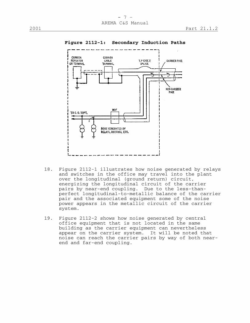
- 7 – AREMA C&S Manual
2001 Part 21.1.2
Figure 2112-1: Secondary Induction Paths
18. Figure 2112-1 illustrates how noise generated by relays and switches in the office may travel into the plant over the longitudinal (ground return) circuit, energizing the longitudinal circuit of the carrier pairs by near-end coupling. Due to the less-than-perfect longitudinal-to-metallic balance of the carrier pair and the associated equipment some of the noise power appears in the metallic circuit of the carrier system.
19. Figure 2112-2 shows how noise generated by central
office equipment that is not located in the same building as the carrier equipment can nevertheless appear on the carrier system. It will be noted that noise can reach the carrier pairs by way of both near-end and far-end coupling.
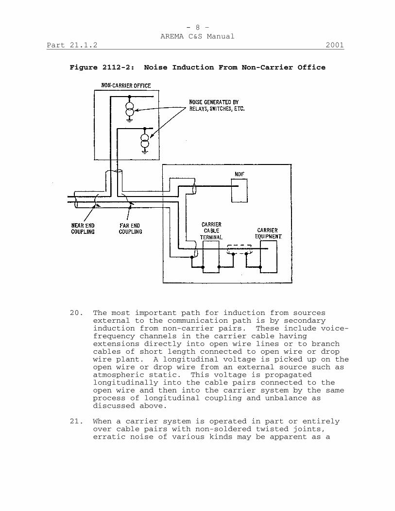
- 8 – AREMA C&S Manual
Part 21.1.2 2001
Figure 2112-2: Noise Induction From Non-Carrier Office
20. The most important path for induction from sources
external to the communication path is by secondary induction from non-carrier pairs. These include voice-frequency channels in the carrier cable having extensions directly into open wire lines or to branch cables of short length connected to open wire or drop wire plant. A longitudinal voltage is picked up on the open wire or drop wire from an external source such as atmospheric static. This voltage is propagated longitudinally into the cable pairs connected to the open wire and then into the carrier system by the same process of longitudinal coupling and unbalance as discussed above.
21. When a carrier system is operated in part or entirely
over cable pairs with non-soldered twisted joints, erratic noise of various kinds may be apparent as a
- 9 – AREMA C&S Manual
2001 Part 21.1.2
result of the variation in resistance of such joints with movement of the conductors due to changes in temperature or wind action. The use of punched sleeves or soldering on carrier pairs should maintain uniformly low resistance over a long period of time.
22. Secondary induction of office noise may be controlled
as follows: a. Plan the carrier system layout so the repeaters or
terminals are physically separated from the source of the noise. In this way, the noise is attenuated before reaching the carrier system. To a large extent this attenuation is due to the loss in the longitudinal circuit of the disturbing conductors. Although it is not possible to estimate longitudinal loss precisely, it may be approximated by using metallic circuit attenuation data.
b. Use a separate carrier-only entrance cable. Here
the noise is attenuated both as it travels over the non-carrier pairs from the office to the junction with the carrier cable and from this point back to the office over the carrier pairs. The noise reduction is, therefore, roughly twice the one-way loss in the cable pairs.
c. Install longitudinal suppression inductors on the
non-carrier pairs. These coils are of two general types, one for use on pairs not employing phantom circuits and the other on pairs that make up phantom circuits. These types of inductors are only used to suppress noise generated in switching offices.
d. Install radio suppression filters in the non-
carrier cable pairs at the main distributing frame of the distributing switching office. These filters should be placed on all non-carrier pairs that enter the carrier cable, with the output wiring segregated from the input wiring.
e. Restrict the length of the carrier repeater
section adjacent to the carrier equipment.
- 10 – AREMA C&S Manual
Part 21.1.2 2001
23. Type 1530A (2-windings) and 1530B (4-windings) or
equivalent inductors are used to suppress longitudinal noise that enters a carrier cable at open wire or drop wire taps. The 1530A inductor is used on non-phantomed pairs and the 1530B is used on pairs that make up phantom circuits. This type of longitudinal noise arises from external sources such as atmospheric static or a radio transmitter.
24. Grounded dc telegraph operated in the same cable with
carrier systems may be an important source of impulse noise. High values of noise may be expected from repeaters whose transmitting relay contacts operate directly into the line. Any high impedance between the relay contacts and the line such as a relay winding, retard coil of a voice-frequency noise killer, or resistance pads, and any low impedance shunts to ground, such as the capacitor in some of the noise killer circuits provides important reductions in the amount of carrier-frequency noise put out on the line.
25. The magnitude and frequency of occurrence of impulse
noise voltages are used to specify objectives for impulse noise on a channel to be employed for data transmission. The objective is expressed as the noise peak level that will be equaled or exceeded a given number of times during a specified period of time on a long-term average basis. This period of time usually is 30 minutes during the busy hour period and the given number of times is 90.
26. Data sets that operate at speeds in the 1000-9600 bits
per second range require a large part of the voice band. In general, these data sets have an effective bandwidth approaching that of C message weighting.
The basic impulse noise objectives are expressed in dbrn using a weighting similar to the C message weighting. They vary somewhat depending upon the type of modulation, gain control and bandwidth employed. However, for data sets operating in the range of 1000-9600 bits, the objectives are set to provide in the order of a 4 to 8 db ratio between the rms power of the data signal as measured by a transmission
- 11 – AREMA C&S Manual
2001 Part 21.1.2
measuring set and the setting of the Impulse Noise Counter. Thus for a data signal level of -16 dbm not more than 15 counts should be obtained with an Impulse Noise Counter setting of 68 dbrn to provide a 6 db ratio, i.e., -16 dbm corresponds to 74 dbrn; 74-68 = 6.
27. Delay-Frequency Characteristics: Data transmission can
be seriously degraded by delay distortion better known as envelope delay distortion. Such distortion results from the variation of the phase characteristic of a channel from perfect linearity. For voice transmission envelope delay distortion is not a problem because the ear is relatively insensitive to minor phase variations.
28. Envelope delay distortion is usually expressed as the
maximum excursion of the envelope delay characteristic within a particular frequency band. It is generally expressed as microseconds over the band. Data sets vary in their tolerance to envelope delay distortion, depending upon the type of modulation and bit speed. The slow speed sets can operate satisfactorily with more envelope delay distortion than is possible with the higher speed sets. The effects of excessive envelope delay distortion show up as high distortion of the data signals and high error rate.
29. Figure 2112-3 shows typical envelope delay or delay
distortion characteristics of various types of carrier channels and a loaded cable circuit. It will be noted that the distortion is very much greater at the extreme ends of the pass band. The delay distortion can be minimized by the application of special networks that effectively flatten out the characteristics shown in the drawing. Such networks are sometimes included as a part of the data sets.
30. Carrier Frequency Error: Carrier frequency error
experienced over a channel has little effect on voice transmission. In the case of data transmission it presents more serious problems. Modulation in data set transmitters results in tones of various frequencies on the channel. These tones are demodulated at the data set receivers to recover the data. If the frequencies of the transmitted tones are
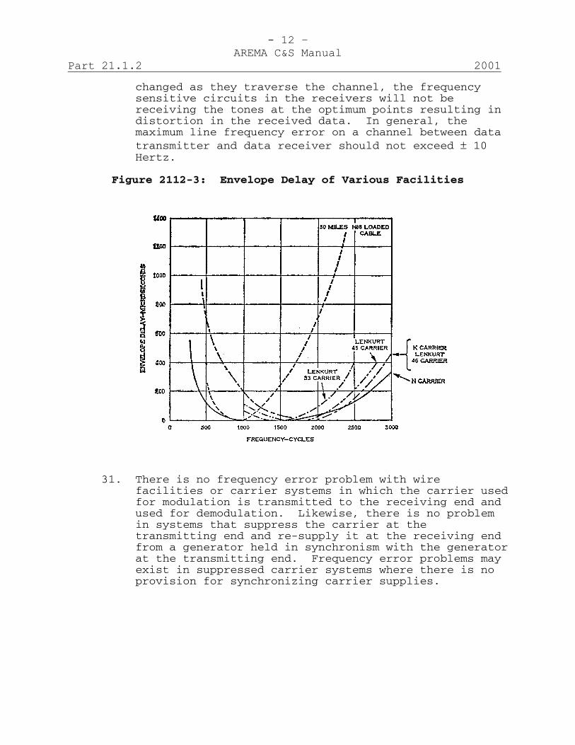
- 12 – AREMA C&S Manual
Part 21.1.2 2001
changed as they traverse the channel, the frequency sensitive circuits in the receivers will not be receiving the tones at the optimum points resulting in distortion in the received data. In general, the maximum line frequency error on a channel between data transmitter and data receiver should not exceed ± 10 Hertz.
Figure 2112-3: Envelope Delay of Various Facilities
31. There is no frequency error problem with wire
facilities or carrier systems in which the carrier used for modulation is transmitted to the receiving end and used for demodulation. Likewise, there is no problem in systems that suppress the carrier at the transmitting end and re-supply it at the receiving end from a generator held in synchronism with the generator at the transmitting end. Frequency error problems may exist in suppressed carrier systems where there is no provision for synchronizing carrier supplies.
AMERICAN RAILWAY ENGINEERING AND MAINTENANCE OF WAY ASSOCIATION
COMMUNICATIONS & SIGNALS MANUAL
Section 22 – Radio
2002

This page intentionally left blank
AREMA® C&S Manual 2002 (Includes 2002 Revisions) Volume 5 Index SECTION 22 - RADIO Part C Type & Subject Pages Status
______________________________________________________________- 1 -
Note: C = Committee responsible for Manual Part.
22.1.1 35-2 Recommended Clean Cab Radio Channel Designators and Railroad Radio Services VHF Frequency Table 1 Reaffirmed 2002 22.1.2 35-2 Listing of Allocated Frequencies in the Railroad Radio Service 1 Extended 2001 22.2.1 35-2 Recommended Design Criteria/ Functional Guidelines for Interface of Radio Communications Module in “Clean Cab” Locomotive 16 Extended 2001 22.2.2 35-2 Recommended Functional/ Operating Guidelines for Remote Control of Engine by Portable Radio 3 Extended 2001 22.2.3 35-2 Recommended Design Criteria for Rack Mounted Frequency Modulated Transceiver and Accessories 14 Extended 2001 22.3.1 35-2 Recommended Guidelines, Considerations and Radio Frequency Requirements for Train Information Systems 39 Extended 2002

This page intentionally left blank
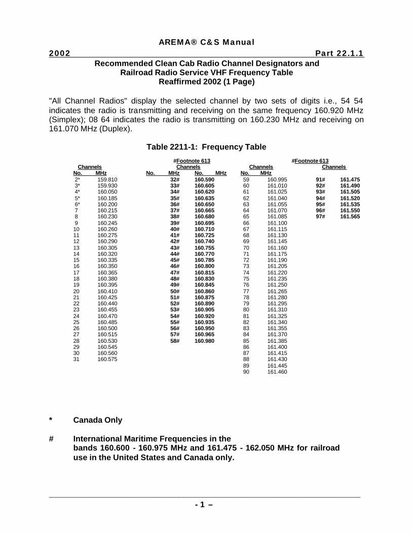
AREMA® C&S Manual
2002 Part 22.1.1
_____________________________________________________________________________ - 1 –
Recommended Clean Cab Radio Channel Designators and Railroad Radio Service VHF Frequency Table Reaffirmed 2002 (1 Page) "All Channel Radios" display the selected channel by two sets of digits i.e., 54 54 indicates the radio is transmitting and receiving on the same frequency 160.920 MHz (Simplex); 08 64 indicates the radio is transmitting on 160.230 MHz and receiving on 161.070 MHz (Duplex). Table 2211-1: Frequency Table #Footnote 613 #Footnote 613 Channels Channels Channels Channels No. MHz No. MHz No. MHz No. MHz 2* 159.810 32# 160.590 59 160.995 91# 161.475 3* 159.930 33# 160.605 60 161.010 92# 161.490 4* 160.050 34# 160.620 61 161.025 93# 161.505 5* 160.185 35# 160.635 62 161.040 94# 161.520 6* 160.200 36# 160.650 63 161.055 95# 161.535 7 160.215 37# 160.665 64 161.070 96# 161.550 8 160.230 38# 160.680 65 161.085 97# 161.565 9 160.245 39# 160.695 66 161.100 10 160.260 40# 160.710 67 161.115 11 160.275 41# 160.725 68 161.130 12 160.290 42# 160.740 69 161.145 13 160.305 43# 160.755 70 161.160 14 160.320 44# 160.770 71 161.175 15 160.335 45# 160.785 72 161.190 16 160.350 46# 160.800 73 161.205 17 160.365 47# 160.815 74 161.220 18 160.380 48# 160.830 75 161.235 19 160.395 49# 160.845 76 161.250 20 160.410 50# 160.860 77 161.265 21 160.425 51# 160.875 78 161.280 22 160.440 52# 160.890 79 161.295 23 160.455 53# 160.905 80 161.310 24 160.470 54# 160.920 81 161.325 25 160.485 55# 160.935 82 161.340 26 160.500 56# 160.950 83 161.355 27 160.515 57# 160.965 84 161.370 28 160.530 58# 160.980 85 161.385 29 160.545 86 161.400 30 160.560 87 161.415 31 160.575 88 161.430 89 161.445 90 161.460
* Canada Only # International Maritime Frequencies in the
bands 160.600 - 160.975 MHz and 161.475 - 162.050 MHz for railroad use in the United States and Canada only.

This page intentionally left blank
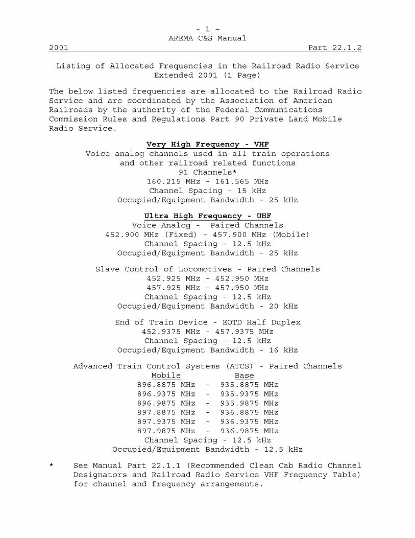
- 1 –AREMA C&S Manual
2001 Part 22.1.2
Listing of Allocated Frequencies in the Railroad Radio ServiceExtended 2001 (1 Page)
The below listed frequencies are allocated to the Railroad RadioService and are coordinated by the Association of AmericanRailroads by the authority of the Federal CommunicationsCommission Rules and Regulations Part 90 Private Land MobileRadio Service.
Very High Frequency - VHFVoice analog channels used in all train operations
and other railroad related functions91 Channels*
160.215 MHz - 161.565 MHzChannel Spacing - 15 kHz
Occupied/Equipment Bandwidth - 25 kHz
Ultra High Frequency - UHFVoice Analog - Paired Channels
452.900 MHz (Fixed) - 457.900 MHz (Mobile)Channel Spacing - 12.5 kHz
Occupied/Equipment Bandwidth - 25 kHz
Slave Control of Locomotives - Paired Channels452.925 MHz - 452.950 MHz457.925 MHz - 457.950 MHzChannel Spacing - 12.5 kHz
Occupied/Equipment Bandwidth - 20 kHz
End of Train Device - EOTD Half Duplex452.9375 MHz - 457.9375 MHzChannel Spacing - 12.5 kHz
Occupied/Equipment Bandwidth - 16 kHz
Advanced Train Control Systems (ATCS) - Paired ChannelsMobile Base
896.8875 MHz - 935.8875 MHz896.9375 MHz - 935.9375 MHz896.9875 MHz - 935.9875 MHz897.8875 MHz - 936.8875 MHz897.9375 MHz - 936.9375 MHz897.9875 MHz - 936.9875 MHzChannel Spacing - 12.5 kHz
Occupied/Equipment Bandwidth - 12.5 kHz
* See Manual Part 22.1.1 (Recommended Clean Cab Radio ChannelDesignators and Railroad Radio Service VHF Frequency Table)for channel and frequency arrangements.

This page intentionally left blank
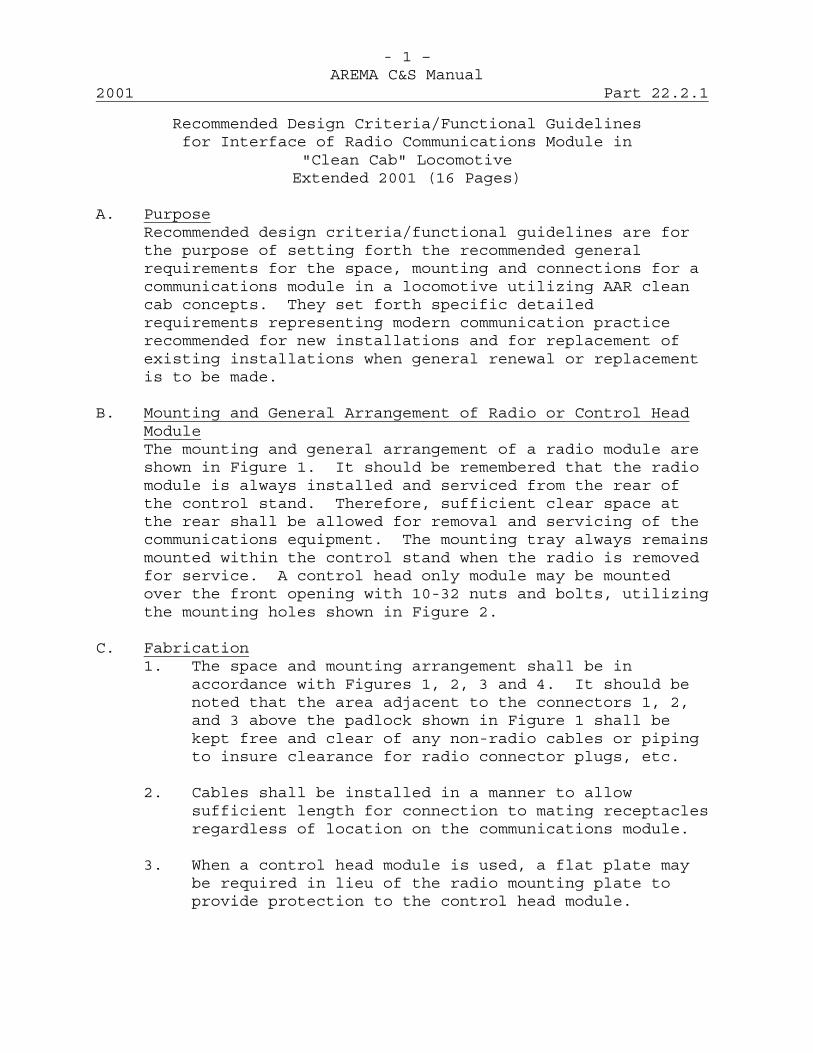
- 1 –AREMA C&S Manual
2001 Part 22.2.1
Recommended Design Criteria/Functional Guidelinesfor Interface of Radio Communications Module in
"Clean Cab" LocomotiveExtended 2001 (16 Pages)
A. PurposeRecommended design criteria/functional guidelines are forthe purpose of setting forth the recommended generalrequirements for the space, mounting and connections for acommunications module in a locomotive utilizing AAR cleancab concepts. They set forth specific detailedrequirements representing modern communication practicerecommended for new installations and for replacement ofexisting installations when general renewal or replacementis to be made.
B. Mounting and General Arrangement of Radio or Control HeadModuleThe mounting and general arrangement of a radio module areshown in Figure 1. It should be remembered that the radiomodule is always installed and serviced from the rear ofthe control stand. Therefore, sufficient clear space atthe rear shall be allowed for removal and servicing of thecommunications equipment. The mounting tray always remainsmounted within the control stand when the radio is removedfor service. A control head only module may be mountedover the front opening with 10-32 nuts and bolts, utilizingthe mounting holes shown in Figure 2.
C. Fabrication1. The space and mounting arrangement shall be in
accordance with Figures 1, 2, 3 and 4. It should benoted that the area adjacent to the connectors 1, 2,and 3 above the padlock shown in Figure 1 shall bekept free and clear of any non-radio cables or pipingto insure clearance for radio connector plugs, etc.
2. Cables shall be installed in a manner to allowsufficient length for connection to mating receptaclesregardless of location on the communications module.
3. When a control head module is used, a flat plate maybe required in lieu of the radio mounting plate toprovide protection to the control head module.

- 2 –AREMA C&S Manual
Part 22.2.1 2001
D. Thermal EnvironmentThe ambient temperature inside the module partition of thecontrol stand shall be within -30°C(-22°F) to 65°C(140°F).
E. Mounting Plate1. The communications module shall be mounted by a plate
as shown in Figures 4 and 5.
2. This radio mounting plate shall be secured to thecontrol stand mounting brackets. Refer to Figures 2, 3and 5.
3. The control stand mounting brackets should be at rightangle to the vertical surface of the control stand.
4. A suitable model of the AAR Clean Cab Radio module hasbeen supplied to all domestic locomotive manufacturersfor the purpose of verification of correct fit.
5. The radio module shall be secured in place within thecontrol stand by a suitable locking device (not aresponsibility of the locomotive manufacturer).
F. Handset Hanger and Cable Opening Location1. When a handset is required, the handset hanger may be
located as shown in Figure 6.
2. A handset cable opening shall be provided as shown inFigure 3.
G. Electrical Connectors1. External Remote Connector: Plug - Amphenol 67-06C14-
12P or approved equivalent. (Mates with 67-02E14-12S.)
2. Antenna Connector (VHF): Plug - Amphenol 83-1SP orapproved equivalent. (Mates with 83-1R)
3. Power Connector: Plug - Amphenol-Straight MS 3106-A-184S or Right Angle MS-3108A-18-4S, Strain Relief MS3057-10-6 or approved equivalents. (Mates with MS-3102A-18-4P)
4. Handset Connector: Plug - Amphenol MS-3106A-14S-6P,Strain Relief MS 3057-6A or approved equivalents,(Mates with MS-3102A-14S-6S-639)
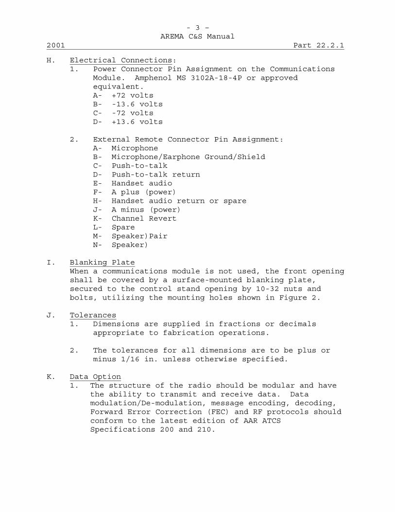
- 3 –AREMA C&S Manual
2001 Part 22.2.1
H. Electrical Connections:1. Power Connector Pin Assignment on the Communications
Module. Amphenol MS 3102A-18-4P or approvedequivalent.A- +72 voltsB- -13.6 voltsC- -72 voltsD- +13.6 volts
2. External Remote Connector Pin Assignment:A- MicrophoneB- Microphone/Earphone Ground/ShieldC- Push-to-talkD- Push-to-talk returnE- Handset audioF- A plus (power)H- Handset audio return or spareJ- A minus (power)K- Channel RevertL- SpareM- Speaker)PairN- Speaker)
I. Blanking PlateWhen a communications module is not used, the front openingshall be covered by a surface-mounted blanking plate,secured to the control stand opening by 10-32 nuts andbolts, utilizing the mounting holes shown in Figure 2.
J. Tolerances1. Dimensions are supplied in fractions or decimals
appropriate to fabrication operations.
2. The tolerances for all dimensions are to be plus orminus 1/16 in. unless otherwise specified.
K. Data Option1. The structure of the radio should be modular and have
the ability to transmit and receive data. Datamodulation/De-modulation, message encoding, decoding,Forward Error Correction (FEC) and RF protocols shouldconform to the latest edition of AAR ATCSSpecifications 200 and 210.
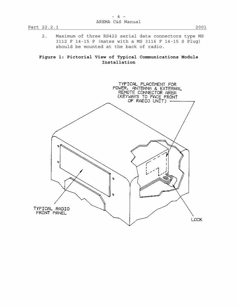
- 4 –AREMA C&S Manual
Part 22.2.1 2001
2. Maximum of three RS422 serial data connectors type MS3112 F 14-15 P (mates with a MS 3116 F 14-15 S Plug)should be mounted at the back of radio.
Figure 1: Pictorial View of Typical Communications ModuleInstallation
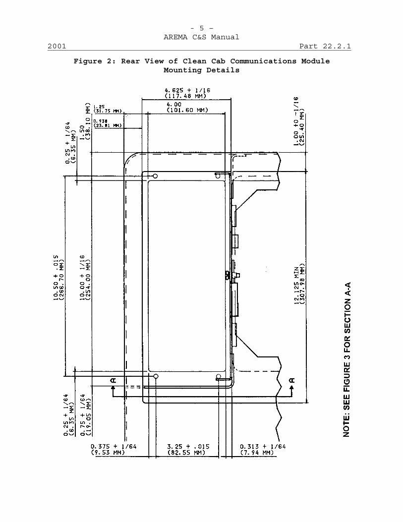
- 5 –AREMA C&S Manual
2001 Part 22.2.1
Figure 2: Rear View of Clean Cab Communications ModuleMounting Details
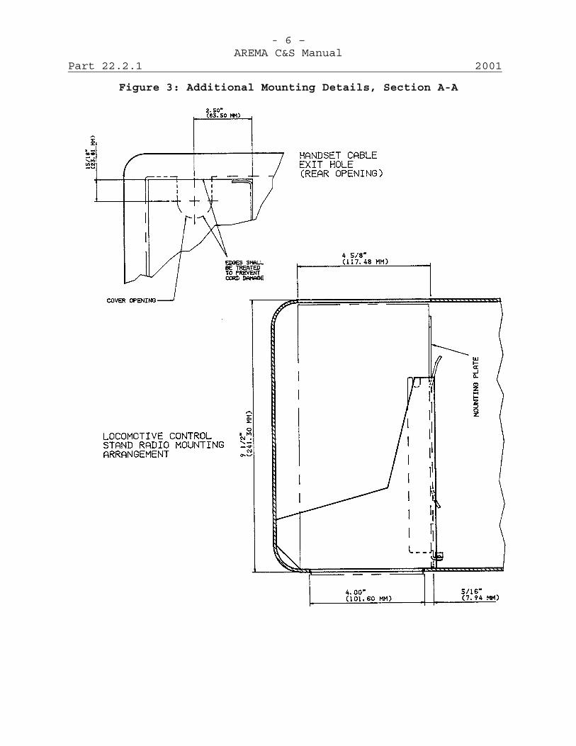
- 6 –AREMA C&S Manual
Part 22.2.1 2001
Figure 3: Additional Mounting Details, Section A-A
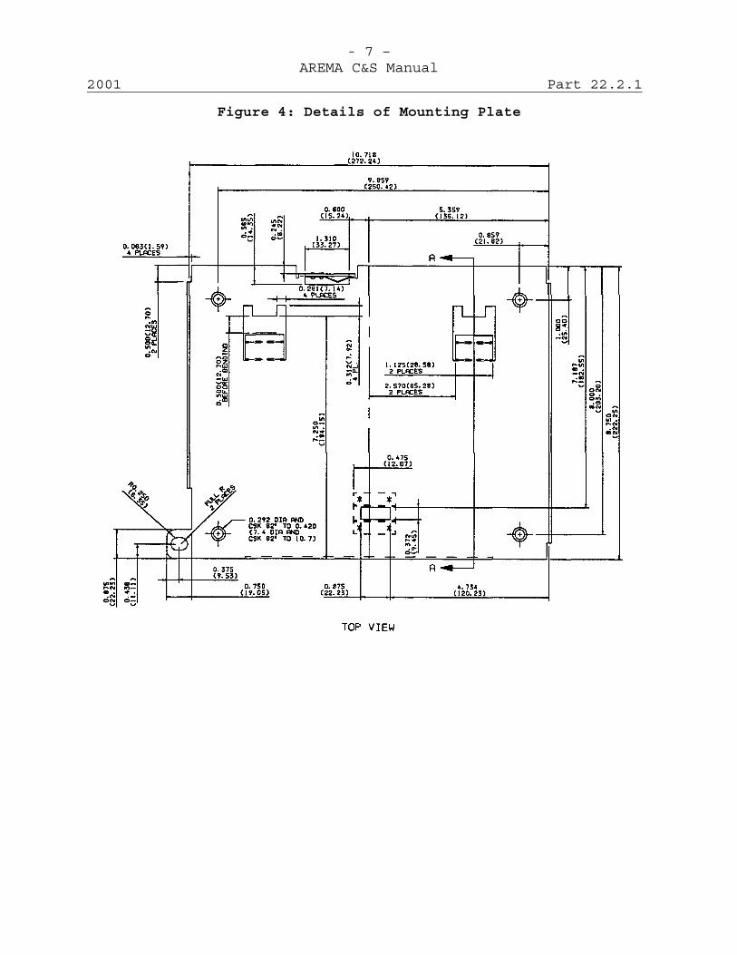
- 7 –AREMA C&S Manual
2001 Part 22.2.1
Figure 4: Details of Mounting Plate

- 8 –AREMA C&S Manual
Part 22.2.1 2001
Figure 5: Additional Details of Mounting Plate

- 9 –AREMA C&S Manual
2001 Part 22.2.1
Figure 6: Additional Details of Mounting Plate

- 10 –AREMA C&S Manual
Part 22.2.1 2001
Figure 7: Additional Details of Mounting Plate

- 11 –AREMA C&S Manual
2001 Part 22.2.1
Figure 8: Isometric View of Mounting Plate Control Stand
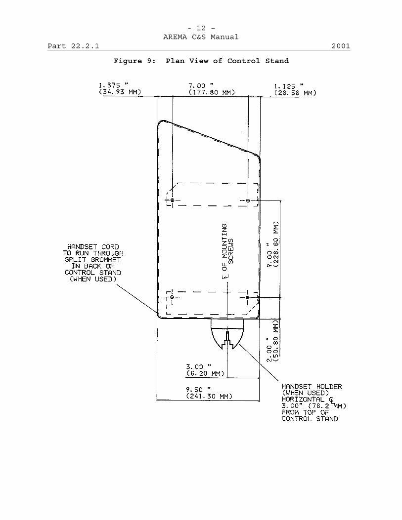
- 12 –AREMA C&S Manual
Part 22.2.1 2001
Figure 9: Plan View of Control Stand

- 13 –AREMA C&S Manual
2001 Part 22.2.1
Figure 10: Angle Iron and Tray Mounting in Control Stand
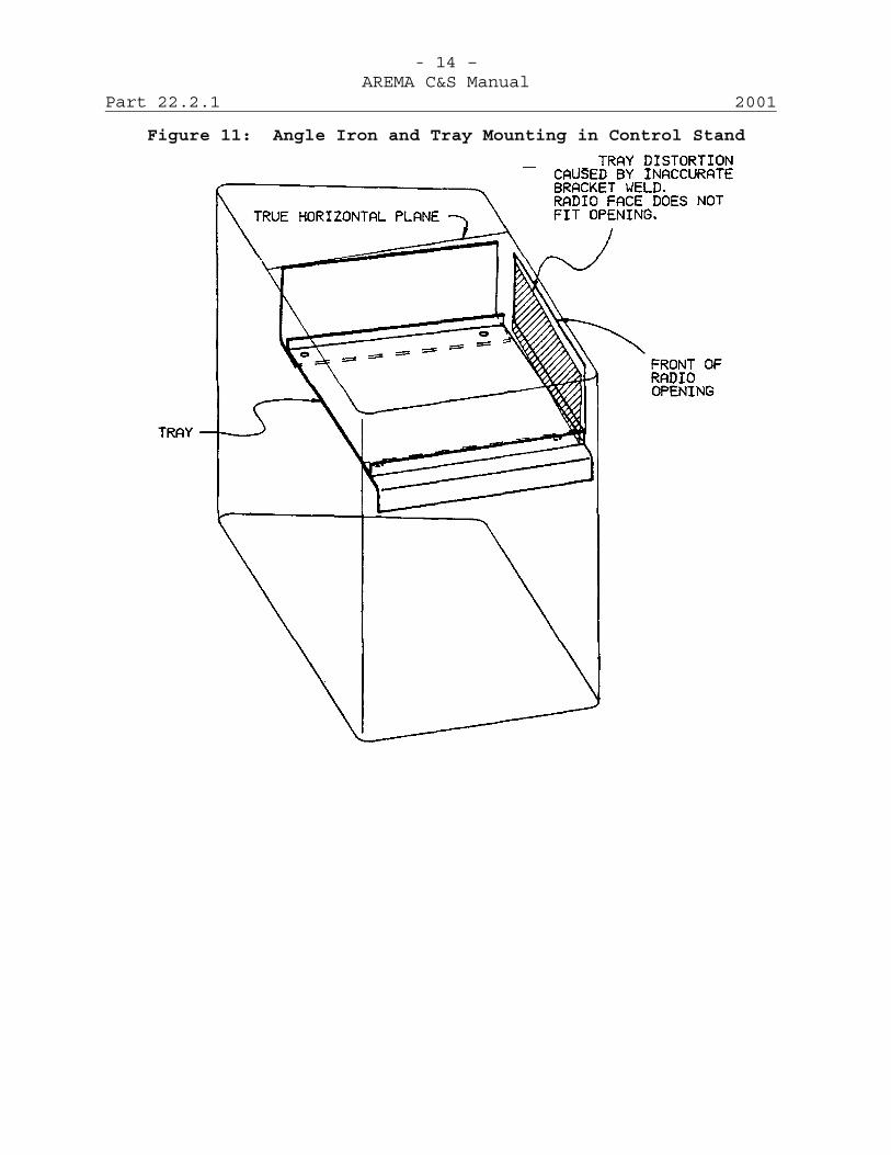
- 14 –AREMA C&S Manual
Part 22.2.1 2001
Figure 11: Angle Iron and Tray Mounting in Control Stand
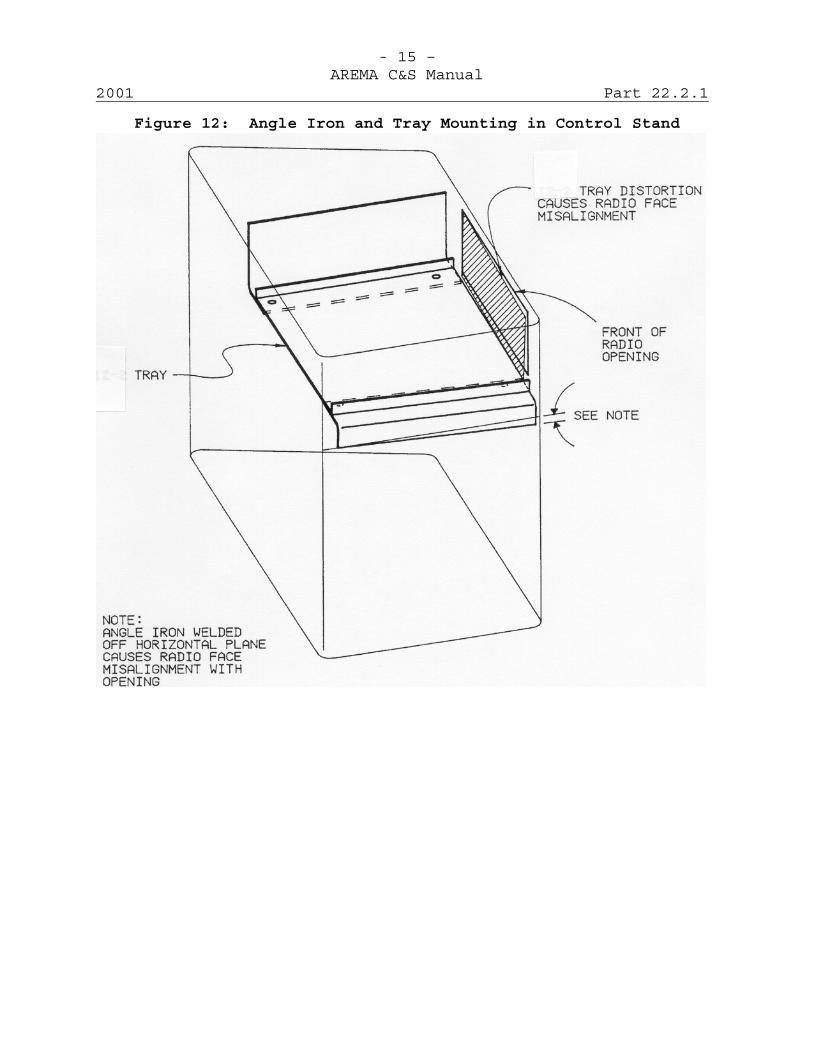
- 15 –AREMA C&S Manual
2001 Part 22.2.1
Figure 12: Angle Iron and Tray Mounting in Control Stand
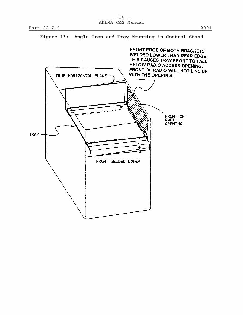
- 16 –AREMA C&S Manual
Part 22.2.1 2001
Figure 13: Angle Iron and Tray Mounting in Control Stand

- 1 –AREMA C&S Manual
2001 Part 22.2.2
Recommended Functional/Operating Guidelinesfor Remote Control of Engine by Portable Radio
Extended 2001 (3 Pages)
A. PurposeThis Manual Part recommends functional/operating guidelinesfor remote control by personnel of an engine in yardswitching service, in hump service, in road switchingservice or in road and terminal service.
B. General1. System shall provide for the remote control of the
following, where required:(a) Direction(b) Throttle(c) Engine Brakes (independent)(d) Train Brakes (automatic)(e) Horn(f) Bell(g) Coupler pins of engine(h) Rail sander(i) Headlight bright or dim(j) Speed selection(k) Dynamic brake(l) Others (to be specified)
2. The system shall be designed so that the engine can beoperated in either the remote control or manual mode suchthat only one mode of operation is functional at a time.Manual movement of the controls when the system is in theremote mode or remote operation of the system with thecontrol in the manual mode will not create an undesiredrelease of brakes or an undesired call for power.
3. System shall provide the following automatic features,where required:(a) Speed regulation (operating, coupling or other)(b) Headlight selection for direction(c) Fire protection(d) Emergency stopping program in case of:
(l) Low air pressure(2) Low oil pressure(3) High engine temperature(4) Fire
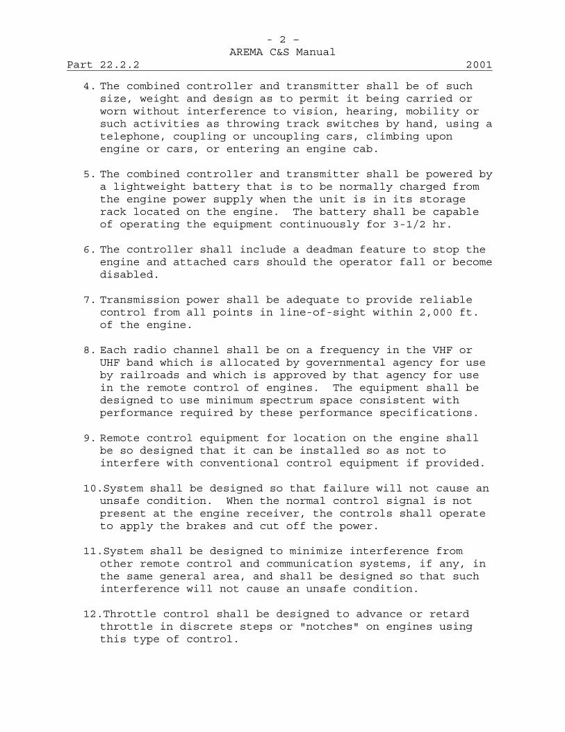
- 2 –AREMA C&S Manual
Part 22.2.2 2001
4. The combined controller and transmitter shall be of suchsize, weight and design as to permit it being carried orworn without interference to vision, hearing, mobility orsuch activities as throwing track switches by hand, using atelephone, coupling or uncoupling cars, climbing uponengine or cars, or entering an engine cab.
5. The combined controller and transmitter shall be powered bya lightweight battery that is to be normally charged fromthe engine power supply when the unit is in its storagerack located on the engine. The battery shall be capableof operating the equipment continuously for 3-1/2 hr.
6. The controller shall include a deadman feature to stop theengine and attached cars should the operator fall or becomedisabled.
7. Transmission power shall be adequate to provide reliablecontrol from all points in line-of-sight within 2,000 ft.of the engine.
8. Each radio channel shall be on a frequency in the VHF orUHF band which is allocated by governmental agency for useby railroads and which is approved by that agency for usein the remote control of engines. The equipment shall bedesigned to use minimum spectrum space consistent withperformance required by these performance specifications.
9. Remote control equipment for location on the engine shallbe so designed that it can be installed so as not tointerfere with conventional control equipment if provided.
10.System shall be designed so that failure will not cause anunsafe condition. When the normal control signal is notpresent at the engine receiver, the controls shall operateto apply the brakes and cut off the power.
11.System shall be designed to minimize interference fromother remote control and communication systems, if any, inthe same general area, and shall be designed so that suchinterference will not cause an unsafe condition.
12.Throttle control shall be designed to advance or retardthrottle in discrete steps or "notches" on engines usingthis type of control.

- 3 –AREMA C&S Manual
2001 Part 22.2.2
13.The radio equipment shall be capable of compliance with allapplicable governmental rules, regulations and standards ineffect at time of delivery.
14.Where required, an alarm device or devices, visible oraudible from a distance of 2,000 ft. under normalconditions, shall be located on the engine to providewarning of low air pressure, wheel slippage, penalty brakeapplication, operation of ground indication relay, or otherabnormal conditions.
15.Systems designed with speed control shall be capable oflimiting the speed of the engine to a maximum of 20 mphwhen it is in the remote control mode.
16.System shall be designed to insure that engine has stoppedbefore power can be applied for movement in the oppositedirection.
17.System shall be designed to insure there is adequate brakepipe or main reservoir pressure to stop the train or enginebefore power can be applied for movement.

This page intentionally left blank
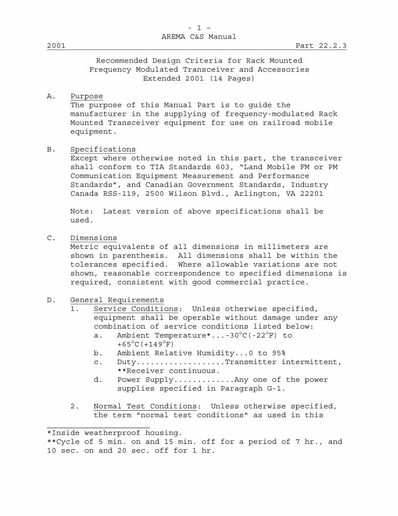
- 1 –AREMA C&S Manual
2001 Part 22.2.3
Recommended Design Criteria for Rack MountedFrequency Modulated Transceiver and Accessories
Extended 2001 (14 Pages)
A. PurposeThe purpose of this Manual Part is to guide themanufacturer in the supplying of frequency-modulated RackMounted Transceiver equipment for use on railroad mobileequipment.
B. SpecificationsExcept where otherwise noted in this part, the transceivershall conform to TIA Standards 603, “Land Mobile FM or PMCommunication Equipment Measurement and PerformanceStandards”, and Canadian Government Standards, IndustryCanada RSS-119, 2500 Wilson Blvd., Arlington, VA 22201
Note: Latest version of above specifications shall beused.
C. DimensionsMetric equivalents of all dimensions in millimeters areshown in parenthesis. All dimensions shall be within thetolerances specified. Where allowable variations are notshown, reasonable correspondence to specified dimensions isrequired, consistent with good commercial practice.
D. General Requirements1. Service Conditions: Unless otherwise specified,
equipment shall be operable without damage under anycombination of service conditions listed below:a. Ambient Temperature*...-30oC(-22oF) to
+65oC(+149oF)b. Ambient Relative Humidity...0 to 95%c. Duty...................Transmitter intermittent,
**Receiver continuous.d. Power Supply.............Any one of the power
supplies specified in Paragraph G-1.
2. Normal Test Conditions: Unless otherwise specified,the term "normal test conditions" as used in this
______________________*Inside weatherproof housing.**Cycle of 5 min. on and 15 min. off for a period of 7 hr., and10 sec. on and 20 sec. off for 1 hr.
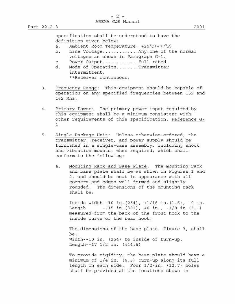
- 2 –AREMA C&S Manual
Part 22.2.3 2001
specification shall be understood to have thedefinition given below:a. Ambient Room Temperature. +25oC(+77oF)b. Line Voltage.............Any one of the normal
voltages as shown in Paragraph G-1.c. Power Output.............Full rated.d. Mode of Operation........Transmitter
intermittent,**Receiver continuous.
3. Frequency Range: This equipment should be capable ofoperation on any specified frequencies between 159 and162 Mhz.
4. Primary Power: The primary power input required bythis equipment shall be a minimum consistent withother requirements of this specification. Reference G-1
5. Single-Package Unit: Unless otherwise ordered, thetransmitter, receiver, and power supply should befurnished in a single-case assembly, including shockand vibration mounts, when required, which shallconform to the following:
a. Mounting Rack and Base Plate: The mounting rackand base plate shall be as shown in Figures 1 and2, and should be neat in appearance with allcorners and edges well formed and slightlyrounded. The dimensions of the mounting rackshall be:
Inside width--10 in.(254), +1/16 in.(1.6), -0 in.Length --15 in.(381), +0 in., -1/8 in.(3.1)measured from the back of the front hook to theinside curve of the rear hook.
The dimensions of the base plate, Figure 3, shallbe:Width--10 in. (254) to inside of turn-up.Length--17 1/2 in. (444.5)
To provide rigidity, the base plate should have aminimum of 1/4 in. (6.3) turn-up along its fulllength on each side. Four 1/2-in. (12.7) holesshall be provided at the locations shown in
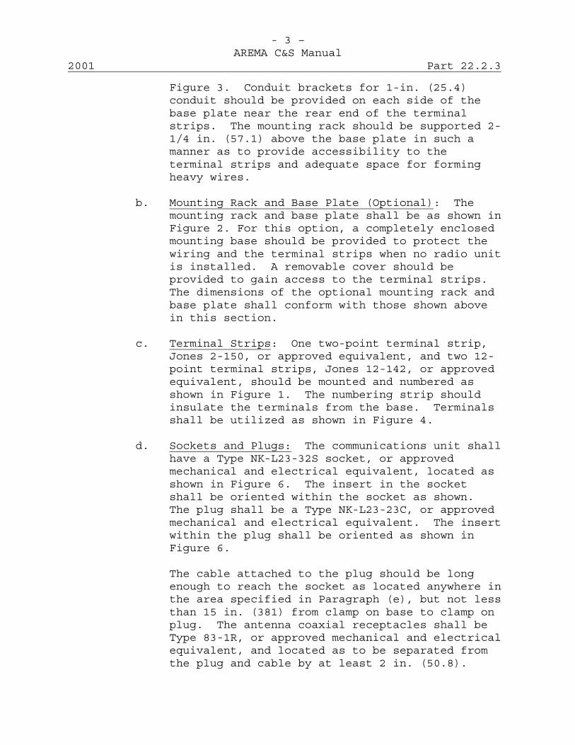
- 3 –AREMA C&S Manual
2001 Part 22.2.3
Figure 3. Conduit brackets for 1-in. (25.4)conduit should be provided on each side of thebase plate near the rear end of the terminalstrips. The mounting rack should be supported 2-1/4 in. (57.1) above the base plate in such amanner as to provide accessibility to theterminal strips and adequate space for formingheavy wires.
b. Mounting Rack and Base Plate (Optional): Themounting rack and base plate shall be as shown inFigure 2. For this option, a completely enclosedmounting base should be provided to protect thewiring and the terminal strips when no radio unitis installed. A removable cover should beprovided to gain access to the terminal strips.The dimensions of the optional mounting rack andbase plate shall conform with those shown abovein this section.
c. Terminal Strips: One two-point terminal strip,Jones 2-150, or approved equivalent, and two 12-point terminal strips, Jones 12-142, or approvedequivalent, should be mounted and numbered asshown in Figure 1. The numbering strip shouldinsulate the terminals from the base. Terminalsshall be utilized as shown in Figure 4.
d. Sockets and Plugs: The communications unit shallhave a Type NK-L23-32S socket, or approvedmechanical and electrical equivalent, located asshown in Figure 6. The insert in the socketshall be oriented within the socket as shown.The plug shall be a Type NK-L23-23C, or approvedmechanical and electrical equivalent. The insertwithin the plug shall be oriented as shown inFigure 6.
The cable attached to the plug should be longenough to reach the socket as located anywhere inthe area specified in Paragraph (e), but not lessthan 15 in. (381) from clamp on base to clamp onplug. The antenna coaxial receptacles shall beType 83-1R, or approved mechanical and electricalequivalent, and located as to be separated fromthe plug and cable by at least 2 in. (50.8).
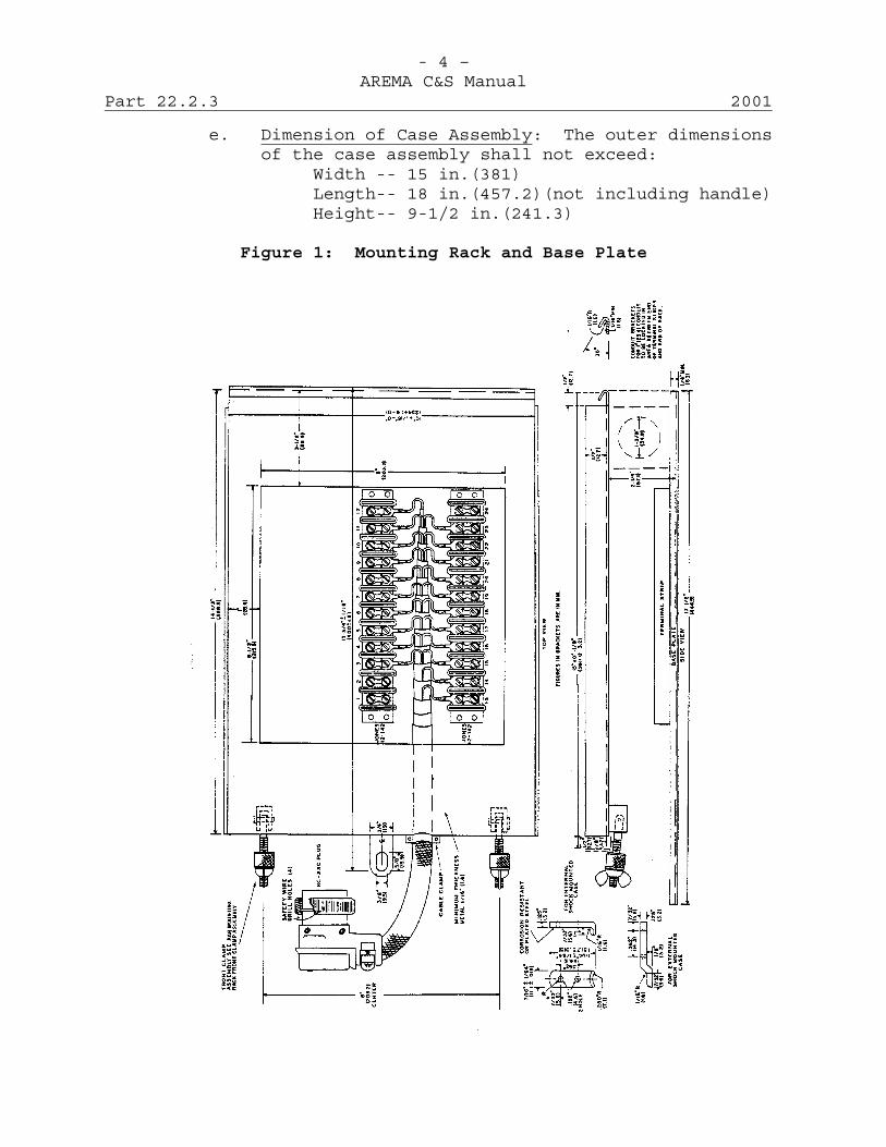
- 4 –AREMA C&S Manual
Part 22.2.3 2001
e. Dimension of Case Assembly: The outer dimensionsof the case assembly shall not exceed:
Width -- 15 in.(381)Length-- 18 in.(457.2)(not including handle)Height-- 9-1/2 in.(241.3)
Figure 1: Mounting Rack and Base Plate
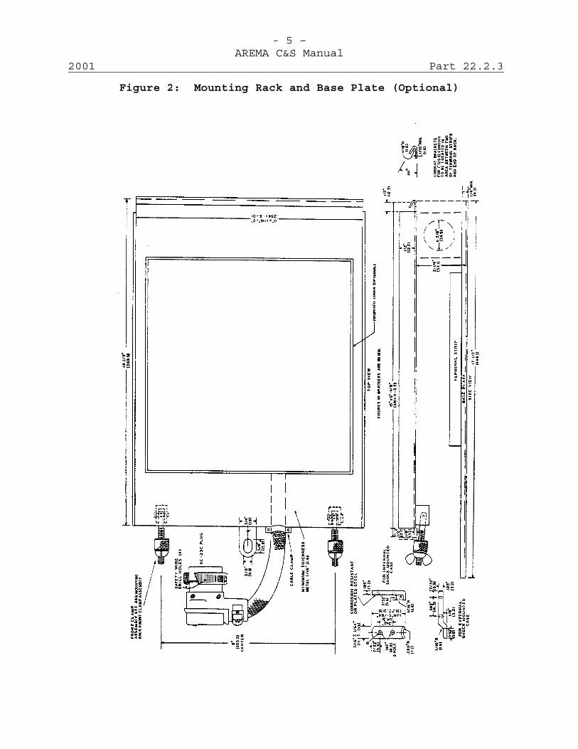
- 5 –AREMA C&S Manual
2001 Part 22.2.3
Figure 2: Mounting Rack and Base Plate (Optional)
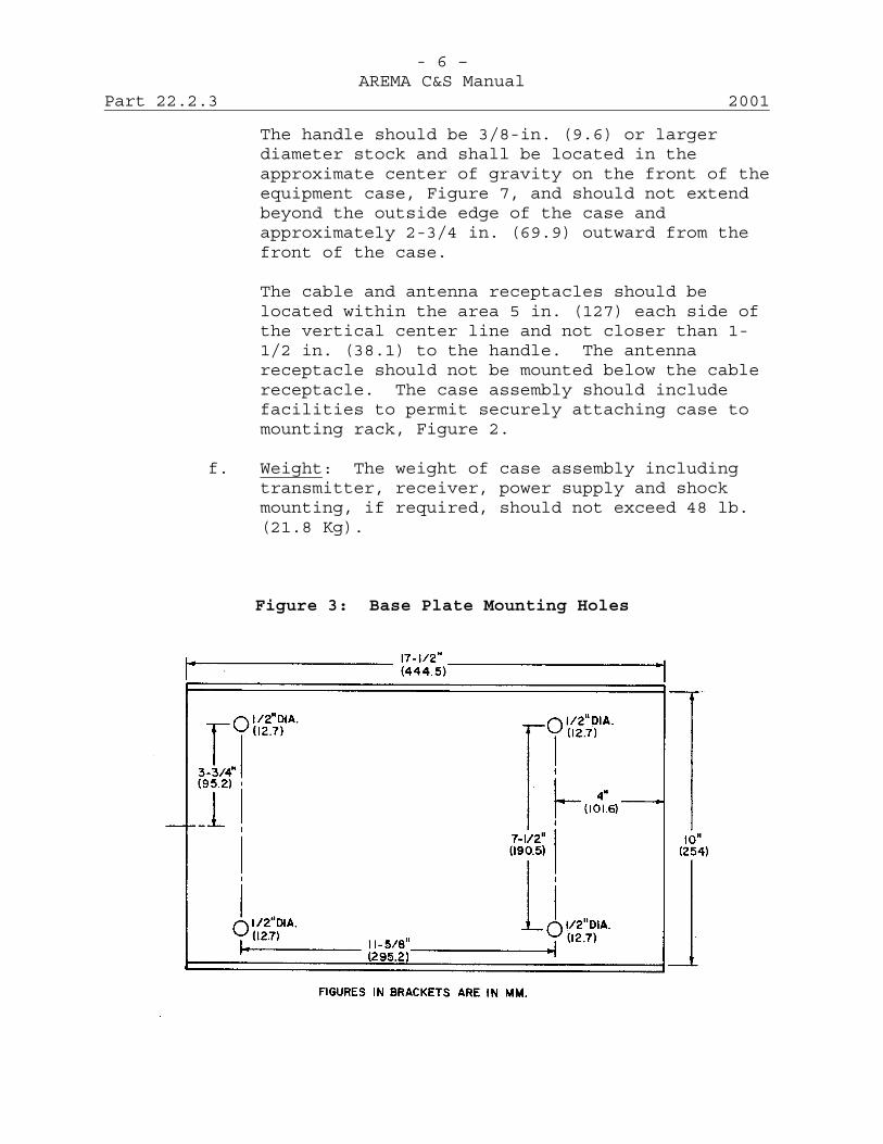
- 6 –AREMA C&S Manual
Part 22.2.3 2001
The handle should be 3/8-in. (9.6) or largerdiameter stock and shall be located in theapproximate center of gravity on the front of theequipment case, Figure 7, and should not extendbeyond the outside edge of the case andapproximately 2-3/4 in. (69.9) outward from thefront of the case.
The cable and antenna receptacles should belocated within the area 5 in. (127) each side ofthe vertical center line and not closer than 1-1/2 in. (38.1) to the handle. The antennareceptacle should not be mounted below the cablereceptacle. The case assembly should includefacilities to permit securely attaching case tomounting rack, Figure 2.
f. Weight: The weight of case assembly includingtransmitter, receiver, power supply and shockmounting, if required, should not exceed 48 lb.(21.8 Kg).
Figure 3: Base Plate Mounting Holes
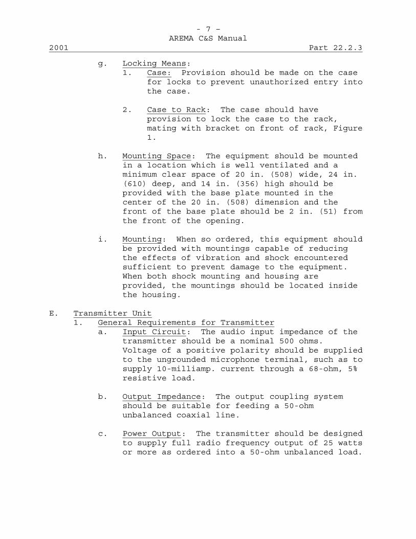
- 7 –AREMA C&S Manual
2001 Part 22.2.3
g. Locking Means:1. Case: Provision should be made on the case
for locks to prevent unauthorized entry intothe case.
2. Case to Rack: The case should haveprovision to lock the case to the rack,mating with bracket on front of rack, Figure1.
h. Mounting Space: The equipment should be mountedin a location which is well ventilated and aminimum clear space of 20 in. (508) wide, 24 in.(610) deep, and 14 in. (356) high should beprovided with the base plate mounted in thecenter of the 20 in. (508) dimension and thefront of the base plate should be 2 in. (51) fromthe front of the opening.
i. Mounting: When so ordered, this equipment shouldbe provided with mountings capable of reducingthe effects of vibration and shock encounteredsufficient to prevent damage to the equipment.When both shock mounting and housing areprovided, the mountings should be located insidethe housing.
E. Transmitter Unit1. General Requirements for Transmitter
a. Input Circuit: The audio input impedance of thetransmitter should be a nominal 500 ohms.Voltage of a positive polarity should be suppliedto the ungrounded microphone terminal, such as tosupply 10-milliamp. current through a 68-ohm, 5%resistive load.
b. Output Impedance: The output coupling systemshould be suitable for feeding a 50-ohmunbalanced coaxial line.
c. Power Output: The transmitter should be designedto supply full radio frequency output of 25 wattsor more as ordered into a 50-ohm unbalanced load.
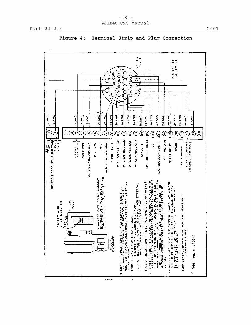
- 8 –AREMA C&S Manual
Part 22.2.3 2001
Figure 4: Terminal Strip and Plug Connection

- 9 –AREMA C&S Manual
2001 Part 22.2.3
Figure 5: Multi-channel Control Unit
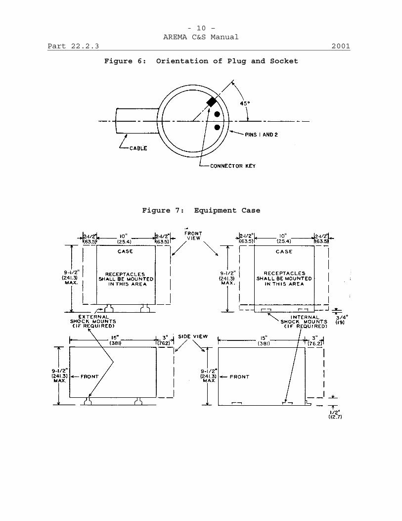
- 10 –AREMA C&S Manual
Part 22.2.3 2001
Figure 6: Orientation of Plug and Socket
Figure 7: Equipment Case

- 11 –AREMA C&S Manual
2001 Part 22.2.3
F. Receiver Unit1. General Requirements for Receiver:
a. Input Impedance: The receiver input circuitshould be designed for operation from a 50-ohmcoaxial unbalanced transmission line.
b. Output Impedance: The receiver should bedesigned to feed an 8-ohm load with one side ofload grounded.
c. Audio Output: Audio output should be at least 8watts with a maximum overall distortion of lessthan 5% measured with 10 microvolt inputmodulated to a peak deviation of 3.5 KHz. Atleast this power should be obtained with a 1microvolt input modulated 90% at 1,000 Hz.Distortion should not exceed that for 10microvolts input at any frequency from 300 to 3KHz.
d. Auxiliary Squelch Control: An auxiliary squelchcontrol circuit may be provided by the radioreceiver unit. This circuit should terminate atTerminal 17 of the standard rack as shown inFigure 4. The control voltage with reference tothe negative battery terminal (gnd.) shouldchange by at least 3 volts, when operating into aload of 50,000 ohms or more, under conditions ofsquelch closed (without signal) changing tosquelch open (with signal). The polarity of thevoltage change should be more positive with"Squelch Open" than with "Squelch Closed". Thecontrol voltage available with squelch closed maybe either zero or + 6 volts. The externalsquelch unit should be so designed that it willoperate satisfactorily from either of thesereference voltages.
G. Power Supply1. Primary Power: Railroad equipment should be capable
of operating from any one of the following powersupplies, as specified by the purchaser.
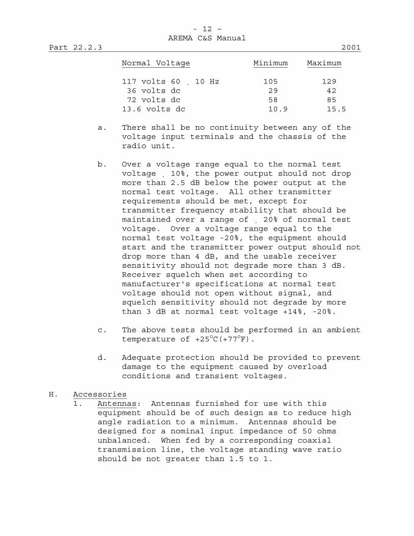
- 12 –AREMA C&S Manual
Part 22.2.3 2001
Normal Voltage Minimum Maximum
117 volts 60 10 Hz 105 12936 volts dc 29 4272 volts dc 58 8513.6 volts dc 10.9 15.5
a. There shall be no continuity between any of thevoltage input terminals and the chassis of theradio unit.
b. Over a voltage range equal to the normal testvoltage 10%, the power output should not dropmore than 2.5 dB below the power output at thenormal test voltage. All other transmitterrequirements should be met, except fortransmitter frequency stability that should bemaintained over a range of 20% of normal testvoltage. Over a voltage range equal to thenormal test voltage -20%, the equipment shouldstart and the transmitter power output should notdrop more than 4 dB, and the usable receiversensitivity should not degrade more than 3 dB.Receiver squelch when set according tomanufacturer's specifications at normal testvoltage should not open without signal, andsquelch sensitivity should not degrade by morethan 3 dB at normal test voltage +14%, -20%.
c. The above tests should be performed in an ambienttemperature of +25oC(+77oF).
d. Adequate protection should be provided to preventdamage to the equipment caused by overloadconditions and transient voltages.
H. Accessories1. Antennas: Antennas furnished for use with this
equipment should be of such design as to reduce highangle radiation to a minimum. Antennas should bedesigned for a nominal input impedance of 50 ohmsunbalanced. When fed by a corresponding coaxialtransmission line, the voltage standing wave ratioshould be not greater than 1.5 to 1.
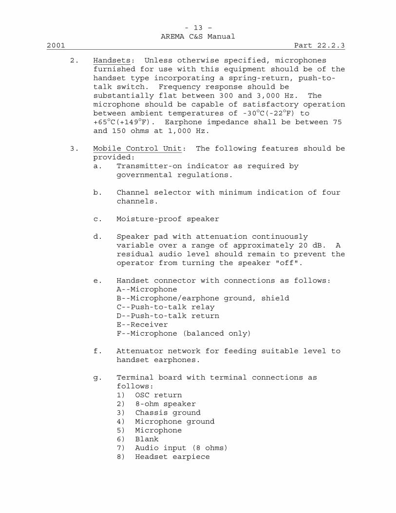
- 13 –AREMA C&S Manual
2001 Part 22.2.3
2. Handsets: Unless otherwise specified, microphonesfurnished for use with this equipment should be of thehandset type incorporating a spring-return, push-to-talk switch. Frequency response should besubstantially flat between 300 and 3,000 Hz. Themicrophone should be capable of satisfactory operationbetween ambient temperatures of -30oC(-22oF) to+65oC(+149oF). Earphone impedance shall be between 75and 150 ohms at 1,000 Hz.
3. Mobile Control Unit: The following features should beprovided:a. Transmitter-on indicator as required by
governmental regulations.
b. Channel selector with minimum indication of fourchannels.
c. Moisture-proof speaker
d. Speaker pad with attenuation continuouslyvariable over a range of approximately 20 dB. Aresidual audio level should remain to prevent theoperator from turning the speaker "off".
e. Handset connector with connections as follows:A--MicrophoneB--Microphone/earphone ground, shieldC--Push-to-talk relayD--Push-to-talk returnE--ReceiverF--Microphone (balanced only)
f. Attenuator network for feeding suitable level tohandset earphones.
g. Terminal board with terminal connections asfollows:1) OSC return2) 8-ohm speaker3) Chassis ground4) Microphone ground5) Microphone6) Blank7) Audio input (8 ohms)8) Headset earpiece
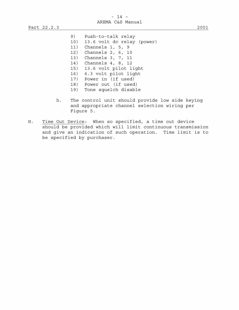
- 14 –AREMA C&S Manual
Part 22.2.3 2001
9) Push-to-talk relay10) 13.6 volt dc relay (power)11) Channels 1, 5, 912) Channels 2, 6, 1013) Channels 3, 7, 1114) Channels 4, 8, 1215) 13.6 volt pilot light16) 6.3 volt pilot light17) Power in (if used)18) Power out (if used)19) Tone squelch disable
h. The control unit should provide low side keyingand appropriate channel selection wiring perFigure 5.
H. Time Out Device: When so specified, a time out deviceshould be provided which will limit continuous transmissionand give an indication of such operation. Time limit is tobe specified by purchaser.
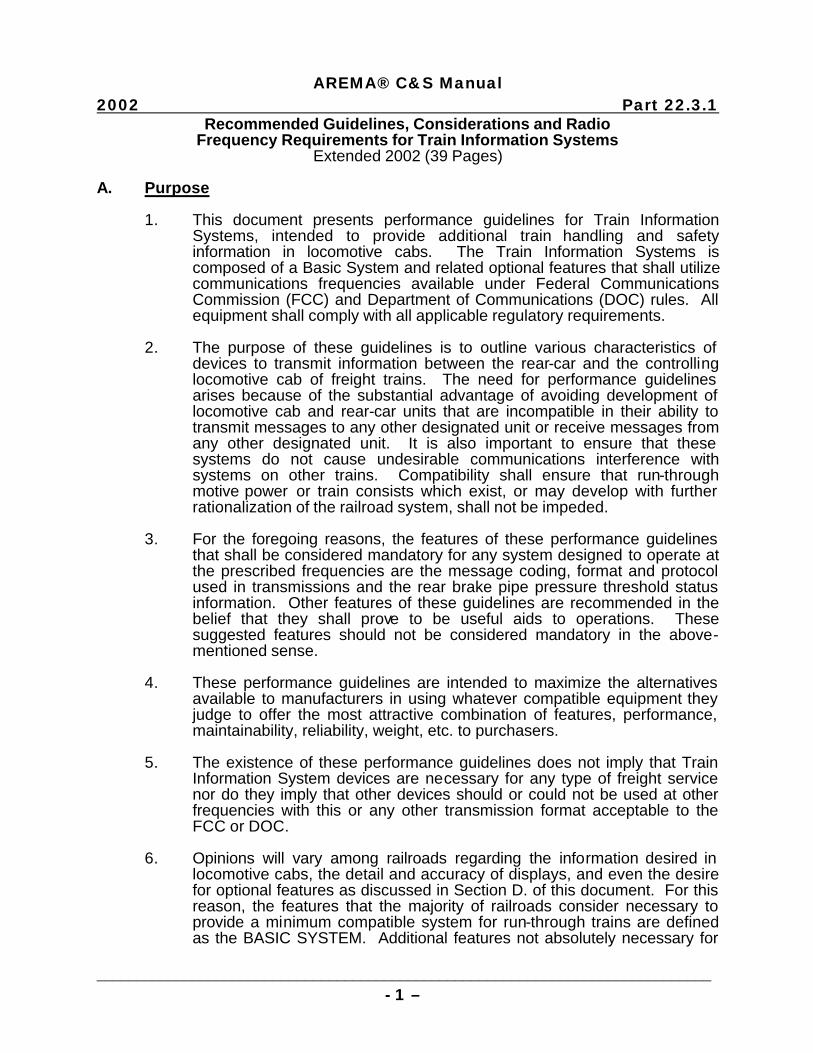
AREMA® C&S Manual
2002 Part 22.3.1
_____________________________________________________________________________ - 1 –
Recommended Guidelines, Considerations and Radio Frequency Requirements for Train Information Systems
Extended 2002 (39 Pages) A. Purpose
1. This document presents performance guidelines for Train Information Systems, intended to provide additional train handling and safety information in locomotive cabs. The Train Information Systems is composed of a Basic System and related optional features that shall utilize communications frequencies available under Federal Communications Commission (FCC) and Department of Communications (DOC) rules. All equipment shall comply with all applicable regulatory requirements.
2. The purpose of these guidelines is to outline various characteristics of
devices to transmit information between the rear-car and the controlling locomotive cab of freight trains. The need for performance guidelines arises because of the substantial advantage of avoiding development of locomotive cab and rear-car units that are incompatible in their ability to transmit messages to any other designated unit or receive messages from any other designated unit. It is also important to ensure that these systems do not cause undesirable communications interference with systems on other trains. Compatibility shall ensure that run-through motive power or train consists which exist, or may develop with further rationalization of the railroad system, shall not be impeded.
3. For the foregoing reasons, the features of these performance guidelines
that shall be considered mandatory for any system designed to operate at the prescribed frequencies are the message coding, format and protocol used in transmissions and the rear brake pipe pressure threshold status information. Other features of these guidelines are recommended in the belief that they shall prove to be useful aids to operations. These suggested features should not be considered mandatory in the above-mentioned sense.
4. These performance guidelines are intended to maximize the alternatives
available to manufacturers in using whatever compatible equipment they judge to offer the most attractive combination of features, performance, maintainability, reliability, weight, etc. to purchasers.
5. The existence of these performance guidelines does not imply that Train
Information System devices are necessary for any type of freight service nor do they imply that other devices should or could not be used at other frequencies with this or any other transmission format acceptable to the FCC or DOC.
6. Opinions will vary among railroads regarding the information desired in
locomotive cabs, the detail and accuracy of displays, and even the desire for optional features as discussed in Section D. of this document. For this reason, the features that the majority of railroads consider necessary to provide a minimum compatible system for run-through trains are defined as the BASIC SYSTEM. Additional features not absolutely necessary for
AREMA® C&S Manual
Part 22.3.1 2002
______________________________________________________________________________ - 2 –
compatible run-through trains are considered OPTIONS. The main purposes for describing the technical features of these Options are:
a. To suggest the direction of further development of compatible
systems by railroads who wish to obtain features beyond the Basic System.
b. To ensure that the installation of such options on locomotives or as
features of the rear-car devices does not prevent equipment so modified from operating with Basic System equipment such that reduces the capability of the basic unit in any way. This requirement is termed "upward compatibility."
7. A further consideration arises from the current U.S. Department of
Transportation requirement for a lighted rear-car marker and through the possible advantages of a common power source for the information and marker systems. It is not the intention of this guideline to attempt to resolve the issue of rear-car marker regulations that differ between federal jurisdictions in the United States, Canada and Mexico. Discussion of a rear-car marker device is explanatory and is not intended as a mandatory requirement, nor is it specifically recommended as a part of the Train Information System.
B. Basic System
This section covers the technical and performance characteristics of the Basic Train Information System. The Basic System will be composed of two units. The Train Information System rear-of-train unit shall be located on the last car of the train and hereafter referred to as the "rear unit" in this document. The second unit that shall receive and display rear car information to the engineer in the locomotive cab shall commonly be referred to as the "cab unit." The message formats and protocol provisions that shall govern data transmissions between the rear and cab units shall be commonly referred to as "communications." Rear unit features are discussed in the next section.
1. Basic System Rear Unit: The rear unit shall determine the status of brake
pipe pressure above or below a preset brake pipe pressure threshold value and transmit this information to the cab unit for display to the locomotive engineer. The rear unit shall be designed for continuous duty service on the rear of trains. The design of the rear unit shall consider the nature and consequences of possible system failure modes in such a way that a fault tolerant design results.
a. Measurement Device:
(1) A Brake Pipe Pressure (BPP) threshold sensing device is
required. The pressure threshold shall be set at nominal 45 psig on decreasing pressure; accuracy " 3 psig.
(2) A means of locally inspecting the brake pipe pressure
outside of the enclosure is highly desirable. Either an integral air pressure indicating device (0-125 psig) or a
AREMA® C&S Manual
2002 Part 22.3.1
_____________________________________________________________________________ - 3 –
quick-disconnect coupling for an external indicating device could be used.
(3) A test fitting, to an appropriate tap size, is desirable. This
fitting could be used with a gauge testing device or a second air gauge to verify accuracy of the integral air gauge, if used.
(4) A glad hand coupling in accordance with AAR Standard S-
4911 is required, arranged as necessary to connect rear unit to the train line. Provisions must be included to maintain the coupling of glad hand fittings in a vibration environment.
(5) A "bleeder valve" is required in the rear unit. This valve shall
permit the release of any air under pressure from the rear car unit and/or associated air hoses prior to detaching the device from the train line.
(6) An internal failure of the measurement device shall not
cause an undesired emergency brake application.
(7) No equipment damage shall occur with pressures up to 200 psig.
b. Reporting Rate: Multiple data transmissions shall occur
immediately following detection of a change of status of the pressure threshold sensing device. During periods of no pressure threshold status change, transmission will be controlled by a randomized interval timer that will be set to generate a message at intervals of 55-65 sec. (nominal 60 sec. time between messages). The randomized interval timer will be reset following each transmission.
c. Electrical Guidelines:
(1) Input Power for Rear Unit: Power for the rear unit will be
provided by removable, internal battery(ies) using universal terminal connectors. It is highly desirable to have a battery minimum operating life of 72 hr. with the optional marker light included in the Basic System. Changing batteries shall not require the use of tools.
(2) Power for Communications Equipment: Input Voltage: 13.6
volts dc ± 20%, negative ground.
(3) Transient Over-voltage Protection: Transient energy must be suppressed to not more than 130 percent of the nominal input voltage.
1 Association of American Railroads Mechanical Division, Manual of Standards and Recommended Practices, Section E, Standard S-491, "Air Brake Hose Coupling ‘Dual Fitting.’"

AREMA® C&S Manual
Part 22.3.1 2002
______________________________________________________________________________ - 4 –
(4) Spurious Energy: Conducted spurious energy shall not cause carrier to be deviated by more than 40 dB below test tone level. Shall comply with regulatory requirements.
d. Characteristics of the Operating Environment: The rear unit must
meet all performance requirements specified herein under all the following environmental conditions and also remain undamaged under the specified non-operating (storage or transport) environmental conditions.
(1) Temperature (ambient at device):
(a) Full performance: -40°F (-40°C) to +140°F (60°C) (b) Operation: -40°F (-40°C) to +140°F (60°C) (c) Storage/Transport: -40°F (-40°C) to +140°F (60°C)
(2) Relative Humidity: 95 percent non-condensing at +122°F (+50°C) (3) Altitude: 12,000 ft MSL (4) Vibration:
(a) Vertical & Lateral: 1 to 15 Hz, 0.5 g peak to peak 15 to 500 Hz, 5 g peak to peak
(b) Longitudinal: 1 to 15 Hz., 3 g peak to peak 15 to 500 Hz., 5 g peak to peak
(5) Shock: 10 g peak for 10 millisec. in any axis. e. Physical Guidelines:
(1) Size: As required. (2) Weight: A maximum 35 lb is recommended. (3) Exterior: A durable finish is required. (4) Mounting: In trailing end of rear car coupler knuckle area. (5) Security: Device locked to car with switch lock. (6) Enclosure: Sealed for service environment, lockable cover,
high security cabinet with a pressure relief safety valve to avoid explosion from high pressure leak inside enclosure.
AREMA® C&S Manual
2002 Part 22.3.1
_____________________________________________________________________________ - 5 –
f. Communications Equipment for Rear Unit: (1) Modulator: See Section B.3., Communications
(2) Radio Transmitter
(a) Frequency: 457.9375 MHz. (b) RF Power Output (pursuant to current regulatory
requirements): 2 Watts. (c) Modulation Designation: 16K0F2D/9Y Peak Deviation of Mark and Space
Frequencies: ±3.0 KHz (d) Spurious: 60dB Minimum below carrier. (e) Deviation: Flat within ±0.5 dB from 300 to 3,000 Hz.
relative to 1,000 Hz. (f) Transmitter Rise Time: Shall not exceed 5ms for 90%
Power and frequency within 1 kHz.
(3) Antenna: Shall be attached to the rear unit.
g. Rear Unit Identification Provisions: Each rear unit shall be assigned a unique identification code that shall be transmitted along with the pressure threshold message to the cab unit. This code ensures that only data transmitted from the assigned rear unit shall be accepted by the cab unit. In this way, rear unit messages from adjacent trains shall be rejected by the cab unit. In order to maintain the interchangeability between rear units and cab units, the identification code shall be reported and selected at the cab unit prior to the start of any train trip.
The unique identification code or "address" shall be in the range 00000 to 99999 and be established in the rear unit electronics by solder strapping or other permanent and secure means. The identification code shall also be clearly indicated on the exterior of the rear unit enclosure. The assignment of identification codes shall be made by the Central Train Information Systems clearinghouse upon written application by a railroad or manufacturer. Once assigned, an identification code number shall remain in effect on the specified rear unit until written notification is given to the clearinghouse by the owning railroad stating that the device is not, and no longer will be, in service. Under no circumstances shall any railroad or manufacturer utilize an identification code not properly assigned by the clearinghouse. Sufficiently large blocks of identification codes shall be assigned to the manufacturers to allow them to utilize proprietary bits and to recognize their equipment.

AREMA® C&S Manual
Part 22.3.1 2002
______________________________________________________________________________ - 6 –
2. Basic System Cab Unit: The cab unit shall receive data messages from the rear unit and display information to the locomotive engineer. The receiver and cab display unit located in the locomotive cab shall be designed for continuous duty service. The design of the cab unit shall consider the nature and consequences of possible system failure modes so that a fault tolerant design results.
a. Cab Display:
(1) Cab displays for the Basic System shall be two indicators that will display the status of rear brake pipe pressure above or below the selected threshold. The display indicators and markings shall be clearly visible and legible from the locomotive engineer's seat position under cab lighting conditions ranging from full sunlight to night illumination. A brightness control shall be provided.
(2) Display functions are as follows: One display indicates BPP
at or above preset threshold brake pipe pressure (i.e., the "Go" condition). The second display indicates BPP below preset threshold brake pipe pressure (i.e., the "No Go" condition). If no communications are received for more than 5 min., the indication of the most recent valid information shall flash until manually reset or communication is restored. If the system is not operating properly (i.e., cab unit or rear unit inoperative or power off), all displays shall be off. If colors are used with display indicators, amber shall indicate below threshold pressure and green shall indicate at or above threshold pressure.
(3) An audible alarm shall be provided which can be clearly
detected in the noise environment of the locomotive cab. The alarm shall sound for 5 sec. duration, or until reset, whenever BPP drops below threshold pressure or communications are lost for more than 5 min.
(4) Any system cab display shall be capable of displaying the
minimum system "Go" and "No Go" status indications regardless of which additional options have been installed on either the rear unit or the cab unit.
(5) A cab unit equipped to display optional information, shall not
present false information upon receipt of a Basic System message from the rear unit.
b. Connections:
(1) Power Connectors: See AAR Standard S-5002 for connector
and pin assignments.
2 Association of American Railroads Mechanical Division, Manual of Standards and Recommended Practices, Section F, Standard S-500,"Communication Module Application - Locomotive Control Stand."
AREMA® C&S Manual
2002 Part 22.3.1
_____________________________________________________________________________ - 7 –
(2) Antenna Connectors: See AAR Standard S-5002 for connector assignment.
(3) Data Connectors: See AAR Standard S-5002 Section 8.2
regarding External Remote Connector.
Data connector use and pin assignments shall be defined by the Central Train Information System clearinghouse on the basis of future system requirements. Twelve pins are reserved.
c. Reporting Rate: Data messages from the rear unit, or repeater
stations where applicable, can be expected to arrive at the cab unit at any point in time.
d. Electrical Guidelines:
(1) Input Power for Cab Unit equipment shall operate from either
of the following voltages: (a) 13.6 volts dc ± 20 percent, negative ground
(b) 72 volts dc nominal, 60 to 80 volts dc operating range,
floating ground, from the locomotive auxiliary electrical system
(2) Transient Overvoltage Protection:
(a) 13.6 volt system: 130% of the nominal input voltage
for 5 sec.
(b) 72 volt system: 5 KV for 10 ms, 90 volts for 5 sec.
(3) Dielectric Strength: 750 volts for 1 min., any circuit to enclosure.
e. Characteristics of the Operating Environment:
The cab unit shall meet all the performance requirements specified herein under all the following environmental conditions and also remain undamaged under the specified non-operating (storage or transport) environmental conditions. (1) Temperature (ambient at device)
(a) Full Performance: +32°F (0°C) to +140°F (60°C) (b) Operation: +32°F (0°C) to 140°F (60°C)
Also see, AREMA C&S Manual, Part 22.2.1 (Recommended Design Criteria/Functional Guidelines for Interface of Radio Communications Module in "Clean Cab" Locomotive) that is an equivalent standard for this purpose.
AREMA® C&S Manual
Part 22.3.1 2002
______________________________________________________________________________ - 8 –
(c) Storage/Transport: -40°F (-40°C) to 140°F (60°C)
Note: The above temperature ranges assume that a cab unit will be located in the locomotive cab area. If not, the -40°F (-40°C) temperature requirement applies as the lower limit in above cases. Conditioning of the internal environment of the enclosure will be permitted on a case-by-case basis. In such cases, a maximum time of 10 min. shall be allowed to condition the equipment to a temperature range consistent with human operator temperature tolerance before operation must commence.
(2) Relative Humidity: 95 percent non-condensing at +122°F
(50°C) (3) Altitude: 12,000 ft above MSL
(4) Vibration:
(a) Vertical & Lateral: 1 to 15 Hz, 0.5 g
peak to peak 15 to 500 Hz, 5 g
peak to peak
(b) Longitudinal: 1 to 15 Hz, 3 g, peak to peak 15 to 500 Hz, 5 g peak to peak
(5) Shock: (a) Vertical and Lateral: 2g peak for 10 millisec.
(b) Longitudinal: 5g peak for 10 millisec.
f. Physical Guidelines:
(1) Dimensions: Dimension and mounting in accordance with
AAR Standard S-500
(2) Displays may be integral with the cab unit enclosure, installed in the locomotive control stand, or separately packaged and mounted per user specifications (e.g., mounted on top of the control stand). If the display is separated from the enclosure, it shall be connected using manufacturer-supplied cables.
AREMA® C&S Manual
2002 Part 22.3.1
_____________________________________________________________________________ - 9 –
(3) AAR Clean Cab Criteria: Any exposed enclosure corners shall conform to the radius standards described in AAR Standards S-5283.
g. Communications Equipment For Cab Unit:
(1) Demodulator: See Section B.3.
(2) Radio Receiver: (Must comply with applicable regulatory
requirements) (a) Frequency: 457.9375 MHz.
(b) Sensitivity: 0.5 microvolt at 20 dBQ
(c) Selectivity: 80 dB protection
(d) Intermodulation Distortion: 80 dB protection
(e) Spurious Response: 85 dB protection
(f) Receiver Discrimination: Flat within
0.5 dB from 300 to 3,000 Hz, relative to 1,000 Hz.
(3) Antenna: The antenna shall be suited for the environment and the mounting location chosen by the user.
h. Unit Identification Provisions: Provisions shall be made for entry of
the rear unit identification code by operating personnel each time a new rear unit is installed on the rear car of the train. The unit addresses shall be on-site user selectable from 00000 to 99999 (e.g., using thumbwheel switches or other suitable means).
3. Communications: The following communications protocol and data
message formats shall be mandatory for the Basic System. a. General: Synchronous Transmission.
b. Modulator/Demodulator:
(1) Modulation Technique: Continuous Phase Fast Frequency
Shift Keying (FFSK)
(2) Modulating Frequencies: Space (0) 1800 Hz ±0.5% Mark (1) 1200 Hz ±0.5%
(3) Transmit/Receive Rate: 1200 baud ±0.5%
3 Association of American Railroads Mechanical Division, Manual of Standards and Recommended Practices, Section F, Standard S-528, "Rounding All Possible Exposed Convex Edges and Corners."
AREMA® C&S Manual
Part 22.3.1 2002
______________________________________________________________________________ - 10 –
c. Data Reporting Rate: The minimum acceptable reporting rate for a Basic System rear unit is described in Section B.1. Communications strategies that employ more frequent transmissions than that described in this section are permitted. However, these strategies shall be consistent with the guidelines set forth herein (especially battery operating life) and strive for efficient use of the radio communications link.
d. Data Message - General: A message transmitted on the
frequency(ies) specified herein shall utilize the format described in the following sections. The general format of any message to be sent is a series of blocks, of fixed length, which contain the data that is to be sent to the front of the train. This format is illustrated as:
BASIC BLOCK OPTIONAL BLOCK 1 OPTIONAL BLOCK 2 Length: 144 bits Length: 144 bits Length: 144 bits TRAIN INFORMATION SYSTEM MESSAGE FORMAT
Every message sent shall always have at least one block, namely the Basic Block. Additional blocks may or may not be sent depending upon the number of optional features built into the system.
At the beginning of every block in the message, a series of synchronization bits shall be sent to allow the transmitter and receiver circuitry to settle and to establish both bit and frame sync. Immediately following the synchronization bits shall be a 45 bit data sequence for the block and an 18 bit BCH error detection/correction code. The block is ended by a trailing bit that is designed to enable the receiver to reliably extract the last bit(s) in the BCH code. The total length of every message block is 144 bits.
The initial block contains all the information that is sent by any Basic System. Included within this initial block is the message type identifier, the rear brake pipe pressure threshold status, rear brake pipe pressure information, motion indications, marker light status, battery(ies) condition, and other discretionary information. Following the Basic Block are Optional Blocks that contain the data from other optional system features that are not provided for in the Basic System message. The number of Optional Blocks, and hence the total length of the message, shall vary depending upon the number of options included in the rear unit, if any, and the strategy the manufacturer uses for transmitting data to the cab unit. Some messages sent by the rear unit, such as the Basic System message will have no Optional Blocks, since all the information to be conveyed is contained in the Basic Block. The maximum

AREMA® C&S Manual
2002 Part 22.3.1
_____________________________________________________________________________ - 11 –
number of Optional Blocks allowed by the message format is four. Specific details about the message format are contained as follows.
e. Basic System Message Format: A message transmitted by the
Basic System shall have the following format. Basic Bit sync4 69 bits Block Frame sync4 11 bits Chaining bits 2 bits Device battery condition 2 bits Message type identifier 3 bits Unit address code 17 bits Rear brake pipe status and pressure 7 bits Discretionary information 11 bits5 Motion detection 1 bit Marker light battery condition 1 bit Marker light status 1 bit Basic block BCH code 18 bits Trailing bit 1 bit Total Length 144 bits
Each of these items is defined in the next section, and the bit-positioning diagram corresponding to this format is given in Appendix B.
f. Basic Block Data Message Elements:
(1) Bit and Frame Sync:
Immediately preceding the start of every basic block transmission, a series of sync bits shall be sent to allow the transmitter and receiver circuitry to settle, and to establish both bit timing and frame synchronization. The bit sync shall be a 69 bit pattern of alternating zeroes and ones (i.e., 0101010101...). The frame sync shall be the eleven bit marker code 01001000111, where the right most bit is the least significant bit (LSB). The frame sync code shall be transmitted LSB first. Note that the bit and frame sync patterns are not considered to be a part of the message information bits for the purpose of generating the BCH error detection/correction code.
(2) Chaining Bits: Chaining bits are a two bit code which
provide information about the position of the current data block within the overall message being received. Chaining bits indicate whether the block is the first block, the last block, or an intermediate block in the message. They may be used in conjunction with the Number of Optional Data Blocks field, described below, to locate the beginning of a
4 See Item B.3.f.(1) 5 For Two-Way Systems see Section C.
AREMA® C&S Manual
Part 22.3.1 2002
______________________________________________________________________________ - 12 –
message in case of an RF dropout. The chaining bits are encoded as follows:
First Chaining Bit (MSB)
0 = The block IS NOT the first block in the message 1 = The block IS the first block in the message
Second Chaining Bit (LSB) 0 = The block IS NOT the last block in the message 1 = The block IS the last block in the message
Thus, a system that transmits only the Basic System message shall encode the chaining bits as binary 11. A more advanced system sending a Basic Block plus two Optional Data Blocks, for example, shall have chaining bits in each message block encoded as binary 10, 00, and 01. The chaining bits shall be sent LSB first.
(3) Device battery condition: Two bits shall be assigned to
monitor the device battery status as follows: MSB LSB 1 1 = Device battery OK 1 0 = Device battery weak 0 1 = Device battery very weak
0 0 = Device battery condition not monitored The LSB will be sent first.
(4) Message Type Identifier: The second element to be transmitted is a three bit code which defines the type of message being transmitted. This information shall be used by the cab unit to identify the format of the message received and enable correct decoding of the contents. Messages from the rear unit of one-way systems shall contain a message type identifier code of zero (0), or 000 in binary. The message type identifier shall be sent LSB first.
Other message type identifiers shall be defined in the future by the Train Information System clearinghouse when requested. These additional message type identifiers could be used for messages from wayside devices to train, or from front to rear of train.
(5) Rear Unit Address Code: The rear unit’s unique address
code shall be the fourth item transmitted in the data message. This code number will be within the range 00000 to 99999 and, therefore, shall require seventeen bits. The address code shall be expressed in binary and sent LSB first.
(6) Rear Brake Pipe Status and Pressure: This seven bit
message element contains the information about the brake
AREMA® C&S Manual
2002 Part 22.3.1
_____________________________________________________________________________ - 13 –
pipe pressure status and brake pipe pressure data, if the rear unit is configured to measure continuous quantitative pressure. The rear brake pipe status and pressure information shall be expressed in binary and transmitted LSB first. For a Basic System, which only monitors brake pipe pressure above or below the threshold, the status information is sent using the codes 126 and 127 expressed in binary. If the actual brake pipe pressure at the rear unit is below the established threshold (i.e., 45 psig.) the status value shall be 126. If the actual brake pipe pressure is greater than or equal to the selected threshold level, then the status code shall be 127.
Advanced units equipped to measure quantitative rear brake pipe pressure shall use this field in a slightly different manner than discussed in the previous paragraph. The brake pipe pressure shall be encoded as a seven bit unsigned binary integer, where one bit represents 1 psig. The allowable range of brake pipe pressures for advanced systems shall be from zero (0) to 125 psig. In this case, the "GO" or "NO GO" brake pipe pressure status shall be deduced in the cab unit by examining the pressure value. Pressures in the range 45 to 125 psig reflect the "GO" status, while pressures 44 psig. and below indicate a "NO GO" brake pipe pressure status.
The table below summarizes the coding and interpretation of the combined brake pipe status and pressure field:
Coded Value (Decimal Representation) Interpretation__
127 "GO" condition from a Basic System rear unit. Brake pipe pressure is at or above threshold pressure.
126 “NO GO" condition from a Basic
System rear unit. Brake pipe pressure is below threshold pressure.
45 through 125 Actual rear brake pipe pressure
value from an advanced system. Pressure at rear unit is at or above threshold pressure (i.e ., a "GO" condition).
0 through 44 Actual rear brake pipe pressure
value from an advanced system. Pressure at rear unit is below
AREMA® C&S Manual
Part 22.3.1 2002
______________________________________________________________________________ - 14 –
threshold pressure (i.e., a "NO GO" condition).
(7) Discretionary Information: Eleven bits shall be used for
discretionary information in one-way systems, at the option of the manufacturer. The use of these bits will be submitted to the Central Train Information System clearinghouse, who shall maintain a record of such on file. All bits not assigned shall be coded as zeroes (0).
(8) Motion detection: One bit shall be assigned to indicate
whether or not the rear car of the train is in motion as follows:
1 = Rear car in motion 0 = Rear car stopped or not monitored
(9) Marker light battery condition: One bit shall be assigned to monitor the marker light battery status as follows:
1 = Marker light battery weak 0 = Marker light battery OK or not monitored
(10) Marker light status: One bit shall be assigned to indicate
whether or not the marker light is lit as follows: 1 = Marker light on 0 = Marker light off or not monitored
(11) Basic Block BCH Code: The basic block BCH code is an 18 bit error detection/correction code for the basic block portion of a message. The BCH code is of the 63,45 type. It shall be computed at the time a message is transmitted by dividing the message block information bits by the generator polynomial g(x) = (18, 17, 16, 15, 9, 7, 6, 3, 2, 1, 0)
The remainder is Exclusively OR'ed with the eighteen bit code and the result becomes the quantity that is sent.
MSB LSB 000011101110110101
The bit and frame sync patterns are not considered part of the block information bits and, therefore, are not included in the BCH code generation process. The BCH Code shall be sent LSB first.
(12) Trailing Bit: One "trailer" bit shall be added to the end of the
Basic Block to enable the last data bits to be reliably received at the cab unit. This bit shall be a one (1).
g. Basic Block Plus Optional Data Block(s): Train Information System
units equipped with options over and above those provided for in the Basic Block shall use additional message blocks to transmit data. The Basic Block is always the first block in the message,
AREMA® C&S Manual
2002 Part 22.3.1
_____________________________________________________________________________ - 15 –
however. The general format for all Train Information System units will be:
Basic Bit sync 69 bits Block Frame sync 11 bits Chaining bits 2 bits Device battery condition 2 bits Message type identifier 3 bits Unit address code 17 bits Rear brake pipe status and pressure 7 bits Discretionary information 11 bits6 Motion detection 1 bit Marker light battery condition 1 bit Marker light status 1 bit Basic block BCH code 18 bits Trailing bit 1 bit Total length 144 bits Optional Bit sync 69 bits Block(s) Frame sync 11 bits Chaining bits 2 bits Block format indicator bit 1 bit Optional block data bits 42 bits Optional block BCH code 18 bits Trailing bit 1 bit Total length 144 bits
(1) Basic Block Elements: All elements of the Basic Block are
described in the previous Section B.3.f. (2) Optional Block(s) Bit and Frame Sync: Immediately
preceding the start of every optional block transmission, a series of sync bits shall be sent to allow the transmitter and receiver circuitry to settle, and to establish both bit timing and frame synchronization. The bit sync shall be a 69 bit pattern of alternating zeroes and ones (i.e., 0101010101...). The frame sync shall be the eleven bit marker code 01001000111, where the right most bit is the least significant bit (LSB). The frame sync code shall be transmitted LSB first. Note that the bit and frame sync patterns are not considered to be a part of the message information bits for the purpose of generating the BCH error detection/correction code.
(3) Chaining Bits: The two chaining bits are coded as described
in the previous Section B.3.f.(2). The chaining bits shall be sent LSB first.
(4) Block Format Indicator Bit: This bit is used to indicate
whether the data contained in the current Optional Data
6 For Two-way Systems see Section C.

AREMA® C&S Manual
Part 22.3.1 2002
______________________________________________________________________________ - 16 –
Block is in binary or ASCII format. Coding for this format indicator bit shall be:
0 = Binary format for data in the block 1 = ASCII format for data in the block
(a) Data in Binary Format: If the indicator bit is zero (0), the remaining 42 bits in the data block are coded in binary using the following format: Data Type "A" Identifier 7 bits
Data "A" 7 bits Data Type "B" Identifier 7 bits Data "B" 7 bits Data Type "C" Identifier 7 bits Data "C" 7 bits Total Data Length 42 bits
The Data Type Identifier is a seven-bit code used to describe or designate the datum which shall immediately follow. Data type identifiers shall be established by the Central Train Information System clearinghouse and shall not be indiscriminately used by a railroad or supplier in an unauthorized manner. Valid data type identifiers shall be in the range of one (1) to 127, expressed in binary representation. Data type identifier zero (0) is a special code and is discussed below. The data type identifier shall be sent LSB first.
The data item appears in conjunction with the data type identifier and contains the information about a particular rear unit parameter associated with one of the optional features of the Train Information System. Generally speaking, each parameter the rear unit reports shall be contained in a separate Data Type Identifier with Data Item pairing, however, some data shall be "packed together" to form related pieces of information to "fill-up" a message element. The coding of each data type shall be defined in the future by the clearinghouse, as requirements arise. Individual data quantities shall be transmitted LSB first.
It should be noted that there is no requirement that all the information that a rear unit could potentially transmit must actually be transmitted when a data message is sent to the cab unit. Any sequence or combination of data parameters may be transmitted, and in any order, so long as the basic rules of message organization are fulfilled. That is, the data type identifier shall precede the datum it describes. In this manner, it is possible for the rear unit equipped with optional features to determine which parameters

AREMA® C&S Manual
2002 Part 22.3.1
_____________________________________________________________________________ - 17 –
shall be transmitted to the cab unit at the time of a transmission and thereby minimize use of the radio transmitter.
If a rear unit does not require all 42 bits in the Optional Block data field to transmit its information, additional bits shall be sent to fill the block to the 42 bit length. This shall be accomplished by using Data Type Identifier zero (0) as a special indication for the "no data" situation. The associated data item shall also be sent as zero (0), or 0000000 in binary.
(b) Data in ASCII Format: If the Optional Block format
indicator bit is a one (1), the following 42 data bits are coded as six seven-bit ASCII characters. Appendix A provides additional information regarding the transmission of ASCII characters in a message.
(5) Optional Block BCH Code: The Optional Block BCH code is
the error detection/correction code for the data portion of a message. It shall be computed at the time a message is transmitted by dividing the data block information bits by the generator polynomial.
g(x)=(18, 17, 16, 15, 9, 7, 6, 3, 2, 1, 0)
The remainder is Exclusively OR'ed with the eighteen-bit code and the result becomes the quantity that is sent.
MSB LSB 000011101110110101
(6) Optional Block Trailing Bit: One "trailer" bit shall be added to the end of any optional data block to enable the last data bits to be reliably received at the cab unit. This bit shall be a one (1).
h. Message Error Detection and Correction Techniques:
A combination of message repetition and error code checking shall be used to provide the reliability necessary for Train Information System communications. These concepts are discussed in the following paragraphs.
(1) Rear Unit Transmission Requirements: A data message
sent by the rear unit shall be sent at least twice. The rear unit must transmit the first message in its entirety before the second repetition of the message is sent. That is, all blocks of the first message shall be transmitted before any repetition of blocks are sent.
A manufacturer may elect to transmit the message more times than these guidelines require.
AREMA® C&S Manual
Part 22.3.1 2002
______________________________________________________________________________ - 18 –
(2) Cab Unit Receiving Requirements: The capability to detect invalid data is provided by the BCH codes in the message. A BCH code shall be generated by the cab unit for each information block, respectively, using the techniques described in previous sections. If the new BCH codes agree with the BCH codes received in the message block(s), the message may be considered valid and decoded. If, however, the BCH codes do not agree, the message shall be considered in error and may be disregarded by the cab unit or, at the discretion of the manufacturer, corrected to become va lid.
The communications guidelines described in this document do not prohibit a manufacturer from using additional error correction techniques, such as "bit averaging" techniques, that may be afforded by multiple repetitions of the message.
C. Application of Train Brakes from Rear Car
The following general assumptions have been made to formulate the guidelines for end-of-train braking systems:
The rear emergency valve is regarded as a backup device, not a braking performance improvement device.
The probability of two trains trying to apply emergency brakes at the same time is very low.
A failure of the system shall not cause application of the emergency brakes.
A 1 sec. delay between the command to apply rear emergency brakes and the rear valve's activation is acceptable.
A requirement for rear of train braking necessitates the provision of two-way communication. Guidelines for two-way transmission given below supplement guidelines in Sections A. and B.
Additional Features - Rear Unit: The addition of two way transmission to the rear unit described in Section B. will provide the additional capability of applying the brakes, restoring normal brake operation, transmission of status information and testing the communications channel on receipt of a command.
1. Brake Application:
The front-to-rear transmission and rear-of-train equipment shall provide for application of train emergency air brakes upon manual selection by the locomotive engineer.
a. An emergency brake application command from the front unit shall
activate the emergency air valve typically within one sec.
AREMA® C&S Manual
2002 Part 22.3.1
_____________________________________________________________________________ - 19 –
b. The rear unit shall send an acknowledgment message to the front unit immediately upon receipt of a brake application command. The front unit shall listen for this acknowledgment and repeat the brake application command if the acknowledgment is not correctly received.
c. The rear unit, on receipt of a properly coded command, will open a
valve in the brake line and hold it open for a minimum of 15 sec. This opening of the valve shall cause the brake line to vent to the exterior.
d. The valve opening and hose diameter shall have a minimum
diameter of 3/4 in. to effect an emergency brake application.
e. Restoring of the braking function (recharging the air brake system) shall be enabled automatically by the rear equipment, no more than 60 sec. after it has initiated an emergency release.
2. Transmission of Status Information:
The rear unit shall transmit the latest status information on receipt of properly coded request. The transmission of the status information will reset the randomized interval timer.
3. Power Requirements:
The radio receiver and support data equipment shall be powered from the same battery pack as the rear unit described in Section B.1.c. and shall still meet all the requirements of Section B.1.
4. Environmental Requirements:
The rear unit equipped with two-way transmission shall meet all the environmental guidelines specified in Section B.1.d.
5. Additional Radio Receiver for Rear Unit:
a. Demodulator: See Section B.3., Communications
b. Radio Receiver:
(1) Frequency: 452.9375 MHz
(2) Sensitivity: 0.5 microvolt at 20 dBQ
(3) Selectivity: 80 dB protection
(4) Intermodulation Distortion: 80 dB protection
(5) Spurious Response: 85 dB protection
(6) Receiver Discrimination: Flat within +/-0.5 dB from 300 to
3,000 Hz, relative to 1,000 Hz.
AREMA® C&S Manual
Part 22.3.1 2002
______________________________________________________________________________ - 20 –
(7) The receiver shall use the same antenna as the rear unit transmitter, with suitable T/R switching provisions.
(8) The address code of the receiver shall be the same as set
for the rear unit identification code described in Section B.1.g.
6. Communications Rear to Front:
The communications protocol and data message formats for rear to front message exchanges shall be identical to that specified under Section B. with the exception that two bits of information are now removed from the discretionary field to become defined. The changed information, together with a new bit-positioning diagram are detailed below.
a. Message Format Rear to Front Communications:
A message transmitted by the rear unit shall have the following format:
Bit sync7 69 bits
Frame sync5 11 bits Chaining bits 2 bits Device battery condition 2 bits
Message type identifier 3 bits Unit address code 17 bits Rear brake pipe status and pressure 7 bits Discretionary information 8 bits Valve circuit status 1 bit Confirmation indicator 1 bit Discretionary information 1 bit Motion detection 1 bit Marker light battery condition 1 bit Marker light status 1 bit Basic block BCH code 18 bits Trailing bit 1 bit Total Length 144 bits
b. Additional Defined Bits: The two new bits are defined below and the new bit positioning diagram corresponding to this format is given in Appendix C-1.
(1) Valve Circuit Status - One bit is assigned to indicate the
status of the Emergency Valve Circuit: 0 = Emergency Valve Circuit failed 1 = Emergency Valve Circuit operational
(2) Confirmation Indicator - One bit is assigned to differentiate between normal updates and responses to requests from the Cab Unit:
7 See Item B.3.f.(1) of basic system

AREMA® C&S Manual
2002 Part 22.3.1
_____________________________________________________________________________ - 21 –
0 = Rear Unit transmission is a normal update 1 = Rear Unit transmission is in response to a
request from the Cab Unit
c. Additional Timing Requirement for Two-Way Operation: When the confirmation bit is set to 1, i.e. when the Rear-to-Front message occurs in response to a Front-to-Rear transmission, the bit sync of the Rear-to-Front message must begin between 12 to 18 millisec. after the end of the Front-to-Rear message.
d. Discretionary Information:
Nine bits will be used for discretionary information at the option of the manufacturer. The use of these bits will be submitted to the clearinghouse, who shall maintain a record of such on file. All bits not assigned shall be coded as zeroes (0).
e. Optional Data Blocks:
Timing constraints between messages does not permit the use of additional optional data blocks, in the two-way system, for transmission of additional information.
7. Additional Features - Cab Unit:
The addition of two-way transmission to the front equipment described in Section B.2., shall provide the additional capability of applying the emergency brakes at the rear end of the train, via an emergency air dump valve, activate by remote control. The capability of requesting transmission of status information from the rear unit and of testing the communications channel shall also be provided.
a. Manual Emergency Brake Activation:
The Cab Unit will have a switch which, when activated, shall initiate a front-to-rear transmission containing an emergency brake application command. On receipt of this command, the brakes shall be applied at the Rear Unit. The switch, distinctively labeled "EMERGENCY", shall be protected, so that there shall exist no possibility of accidental activation.
b. Manual Communications Test:
Means shall be provided for manual initiation of an end-to-end test of the front-to-rear communications link with a visual/audible indication of success or failure of the test. Activation of a manual, communications link test shall simultaneously set a distinctive symbol on the display and transmit a request for an update of the status information from the rear unit. The distinctive symbol will be cleared when the new status information (containing the confirmation indicator Bit = 1) is received in the following rear-to-front transmission. This indicator is also cleared by any subsequent successful front-to-rear/rear-to-front confirmation cycle.
c. Automatic Communications Test:
The availability of the front-to-rear communications link shall be checked automatically at least every 10 min.
AREMA® C&S Manual
Part 22.3.1 2002
______________________________________________________________________________ - 22 –
d. Emergency Valve Test: Means shall be provided to confirm availability and proper functioning of the emergency valve as part of both the manual (item b) and automatic (item c) communications tests.
e. Rear to Front Communications Failure:
(1) The cab unit shall be so designed that if no rear-to-front
transmission is received for a period of 196 sec. a request shall automatically be transmitted to the rear unit for an update of status information. If a message has not been received after this request, another request shall be sent 15 sec. after the first. If no communication is received for a period of 326 sec., another status update request shall be transmitted to the rear unit. If, after 15 sec., no status update has been received, another status update request shall be transmitted. If after this fourth status update request no status update has been received, Rear-to-Front communication failure shall be declared.
(2) Display or indication of Rear-to-Front communication failure
shall take precedence over Front-to-Rear communication failure.
f. Front-to-Rear Communications Failure:
Every 10 min. a status update request shall automatically be sent to the rear unit. If no status update is received as a result of this transmission, (i.e. with confirmation bit = 1) a second request shall be sent 15 sec. later. If still no status update has been received, a third request shall be repeated 6 min. later. If still no status update has been received, a fourth request shall be sent 15 sec. later.
If after the fourth update request no update has been received (with confirmation bit = 1), then Front-to-Rear communication failure shall be declared. This warning shall be reset by the next successful front-to-rear/rear-to-front confirmation cycle (automatically or manually initiated).
Front-to-rear communication failure shall also be tested and declared during an attempted emergency activation (Item C.7.a.).
g. Front-to-Rear Message Retries:
The cab unit will handle data message retries as follows:
(1) For emergency brake application commands, the retries shall continue until a status update indicates that the rear unit has received the command by setting the confirmation bit in the update. Thereafter if the rear brake pipe pressure has not been reduced to a level below 5 psi within 4 sec., another retry shall be made and again the confirmation bit looked for. This process shall repeat up to a maximum time of 2 min. after the last emergency switch activation. If a
AREMA® C&S Manual
2002 Part 22.3.1
_____________________________________________________________________________ - 23 –
confirmation bit has not been received within 15 sec. of the initial or a 4 sec. retry emergency command, front-to-rear communication failure shall be declared.
(2) For manually initiated status information update requests,
the cab unit shall not transmit any retries automatically, nor cause a communication failure indication.
h. Power Requirements:
The additional radio transmitter and support data equipment shall be powered from the same power source as the cab unit receiver described in Section B.2.d.
i. Environmental Requirements:
The additional equipment included in the cab unit for two way transmission shall meet the environmental guidelines described in Section B.2.e.
j. ID Code:
The ID code transmitted by the cab unit transmitter shall be identical to that selected for message reception from the rear detailed in Section B.2.h.
k. Additional Radio Transmitter for Cab Unit:
(1) Modulator: See Section B.1. Communications
(2) Radio Transmitter (a) Frequency: 452.9375 MHz (b) RF Power Output: RF power of the Front-to-Rear
radio link shall be 2 watts nominal unless a greater power output is permitted by regulatory authorities, throughout the operating territory of the equipment. Nominal radio power under any circumstances shall not exceed 8 watts.
(c) Modulation Designation: 16K0F2D/9Y
Peak Deviation of Mark and Space Frequencies: +/-3.0 KHz.
(d) Spurious: 60 dB Minimum below carrier
(e) Deviation: Flat within +/-0.5 dB from 300 to 3,000 Hz, relative to 1,000 Hz.
(f) Transmitter Shall not exceed 5 ms for 90%
Rise Time: power and frequency within 1 KHz
AREMA® C&S Manual
Part 22.3.1 2002
______________________________________________________________________________ - 24 –
(g) The transmitter shall use the same antenna as the cab unit receiver with suitable T/R switching provisions.
(h) The transmitter identification code shall be the same
as that selected in Section B.2.h.
8. Communications Front to Rear:
The following communications protocol and data message formats shall be mandatory for the front to rear communications link.
a. Governing Factors:
The following items were considered when formulating the guidelines for the front to rear protocol.
(1) Since the front to rear communications protocol now
concerns a control function as well as telemetry, additional code security is desirable.
(2) An emergency brake application command from the front
unit shall activate the emergency air valve typically within 1 sec.
(3) The front-to-rear radio link shall achieve a single
transmission success rate of 98% or better, averaged over typical railroad operating terrain, for a train length of 5,000 ft. The intent of this requirement is for this link to have the same performance in terms of throughput, as the Rear-to-Front link.
(4) To enable functioning of two-way telemetry on more than
one train in close proximity (radio range), no unit can be allowed to flood either radio channel, with a long continuous burst of message transmission.
(5) Performance of Rear-to-Front communication shall not be
degraded by the Front-to-Rear link.
b. General: Synchronous transmission
c. Modulator/Demodulator: The modulation scheme shall be identical to that described in Section B.1.3., for the one way system.
d. Transmission:
The Front-to-Rear radio channel shall operate at 452.9375 MHz. All other parameters describing this radio channel including band width and stability shall be as stated in the guidelines for the one-way system.
AREMA® C&S Manual
2002 Part 22.3.1
_____________________________________________________________________________ - 25 –
e. Transmission Format Front to Rear Communications: Any message sent from the front unit to the rear unit, shall utilize the format described in the following sections:
(1) Each message shall consist of three identical data blocks.
(2) At the beginning of the message (before first data block only)
a series of synchronization bits shall be sent to allow the transmitter and receiver circuitry to stabilize and to establish both bit and frame sync.
(3) Immediately following the synchronization bits, shall be a 30
bit data sequence for the block followed by a 33 bit BCH error detection code.
(4) Each data block is followed by a single odd parity bit.
(5) The total length of each message is 672 bits.
f. Message Format Front to Rear Communications:
A message transmitted by the front unit shall have the following format:
Bit Sync 456 bits
Frame Sync 24 bits Data Block 63 bits Odd Parity Bit 1 bit Data Block (Repeat #1) 63 bits Odd Parity Bit 1 bit Data Block (Repeat #2) 63 bits Odd Parity Bit 1 bit Total length 672 bits
g. Data Block Format:
(1) Each of the three data blocks shall have an identical format.
(2) The format within each block shall consist of 30 information bits followed by 33 BCH error check bits conforming to the (63.30) format.
(3) The general format of each data block is as follows:
Chaining Bits 2 bits (always 11)
Message Type Identifier 3 bits (always 000) ID 17 bits Command word 8 bits Status Request or Emergency BCH Code 33 bits
h. Message Data Block Elements: (In Order Transmitted)
AREMA® C&S Manual
Part 22.3.1 2002
______________________________________________________________________________ - 26 –
(1) Bit Sync: Immediately preceding the start of every basic block transmission, a series of sync bits shall be sent to allow the transmitter and receiver circuitry to settle, and to establish both bit timing. The bit sync shall be a 456-bit pattern of alternating zeroes and ones (i.e., 010101010101...)
(2) Frame Sync:
Immediately following the bit sync pattern. A frame sync code shall be transmitted to establish frame synchronization.
The frame sync used shall be the 24-bit code:
1000 1111 0001 0001 0010 1001
The left bit in the above code is the LSB, transmitted first. Note that the bit and frame sync patterns are not considered to be a part of the message information bits for the purpose of generating the BCH error detection/correction code.
(3) Chaining Bits:
Chaining bits are a two-bit code which provide information about the position of the current data block within the overall message being received. Chaining bits indicate whether the block is the first block, the last block, or an intermediate block in the message.
For the Front to Rear protocol, the first (and only) block is uniquely identified by the chaining bits 11, signifying only one block in the message. The left hand bit is MSB. Note that for the Front to Rear protocol, the 2nd and 3rd blocks are repeats of the first block.
(4) Message Type Identifier:
The message type identifier is a 3-bit code used to define the type of message being transmitted by the cab unit. For two-way end of train systems this code shall be all zeroes (000).
(5) ID Code:
Unique ID code of the rear unit being addressed shall be the next item in the data message. This code number will be within the range 00000 to 99999 and, therefore, shall require seventeen bits. The address code shall be expressed in binary and sent LSB first.
(6) Command Word:
The left bit in the below code is the MSB and sent LSB first. An 8-bit command word shall be used for the following two functions:
(a) Status Update request from front unit:

AREMA® C&S Manual
2002 Part 22.3.1
_____________________________________________________________________________ - 27 –
01 01 01 01
(b) Emergency Brake Application 10 10 10 10
(7) BCH Code:
The BCH code used for Front-to-Rear transmissions is a 33-bit detection/correction code applied only to the data portion of the block. The BCH code is of the (63.30) type and is computed at the time a message is transmitted by dividing the message block information bits by the generator polynomial:
g(x)=(33,32,30,29,28,27,26,23,22,20,15,14,
13,11,9,8,6,5,2,1,0) This remainder is the result that is sent.
The BCH code shall be sent LSB first. Note that the bit sync and frame sync patterns are not considered part of the block information bits and therefore, are not included in the BCH generation process.
(8) Parity Bit:
An odd parity bit shall be added at the end of each data block. The bit-positioning diagram corresponding to this format is given in Appendix C-2.
D. Optional Features
This section discusses several optional features that could be added to the Basic System. As previously indicated, the Basic System is defined as the minimum system necessary to ensure compatible operation for run-through trains. Most of the options to be discussed become feasible as a result of installing onboard the train those minimum data processing and communications capabilities provided by the Basic System. With relatively modest increases in data processing, communications, and display capabilities over and above capabilities provided by the Basic System, a number of optional features become viable. The selection of which option(s) is/are to be selected resides entirely with the acquiring railroad. Many of the options are highly desirable to some railroads. However, the various optional features described below can be added to the Basic System, if and only if, the minimum compatible operations are not in any manner compromised by the incorporation of any optional feature.
The options to be discussed are as follows:
Option 1 - Rear End Marker Device Option 2 - Multiple Brake Pipe Pressure Threshold Switches Option 3 - Brake Pipe Pressure Transducer
Option 4 - Rear Car Movement Indicator Option 5 - Built-in Battery Charger for Rear Unit Option 6 - Rear Unit Status Monitoring
AREMA® C&S Manual
Part 22.3.1 2002
______________________________________________________________________________ - 28 –
Option 7 - Rear Car Slack Status Detection Option 8 - Rear Car Brake Cylinder Release Detection Option 9 - Undesired Emergency Location Option 10- Emulation of Rear Car Brake Control Valve Activity Option 11- Deleted, See Section C Option 12- Automatic Initial Terminal Air Brake Test Option 13- Voice Warning and Advice Option 14- Hot Box, Dragging Equipment and Other Defects Cab Display Option 15- Train Orders Cab Display Option 16- Automatic Train Location
Option 17- Mid-Train Slack and Brake Pipe Pressure Detectors Option 18- Disabled Train Warning Light Option 19- Rear Car Acceleration Indicator Option 20- Front Unit Authorization for Additional Security in Two-Way Systems
It should be noted that discussions of options, is not intended to suggest that any single option or combination of options is a requirement. Each railroad should make these choices based upon its own needs and objectives. It is the intent of this section to enable the maximum opportunity to tailor the most effective Train Information System that should meet the individual needs of each using railroad. It should also be restated that any option or combination of options ins talled in any system shall not in any manner interfere with or constrain operation with a companion unit configured for Basic System capabilities. Furthermore, options shall meet applicable environmental specifications established for related Basic System units and components.
The following paragraphs discuss the various options.
1. Rear End Marker Device: A lighted rear marker device is currently
required by Title 49 CFR Part 221 on trains operating in the United States. Other jurisdictions (e.g. Canada, Mexico) also have requirements that are different from those described in 49 CFR Part 221. Because of these requirements, there may be advantages for some railroads to incorporate a rear marker device as an optional feature to their basic Train Information System.
This section briefly addresses the issue of a rear-of-train marker device insofar as it concerns Train Information System design. These provisions are offered only as an explanation of ideas for meeting statutory requirements with this type of system in a reasonable manner. In no way do these provisions constitute an endorsement, specification or mandatory requirement for a marker light feature in a Train Information System. If a marker device (light) is installed as an optional feature in a Train Information System, the following points should be considered:
a. The marker device be an integral part of the rear unit.
b. All statutory requirements be met by the marker device, including
Title 49 CFR Part 221 for a U. S. installation or other applicable regulation for a foreign application.
AREMA® C&S Manual
2002 Part 22.3.1
_____________________________________________________________________________ - 29 –
c. The marker device power requirements have a minimal impact on the rear unit battery life. See Section B.1.c.
d. The operation of the marker device be unaffected by the operation
of any other rear unit optional feature, within the limits of the battery life.
e. A marker device status indication be developed at the rear unit,
transmitted to the cab unit as one of the data parameters and displayed to the engineer.
f. Ease of field servicing and reliability be emphasized in the design of
the marker device.
2. Multiple Brake Pipe Pressure Threshold Switches: An optional feature that could be incorporated into the Basic System is one or more additional pressure threshold switches. The additional pressure threshold intervals would permit additional brake pipe pressure functions. For example, a 10 psig pressure switch could be used to power down the rear unit during extended periods when Brake Pipe Pressure (BPP) was zero. Other intervals could be selected by using railroads. Additional display devices would be needed. However, these additional devices shall not interfere with the planned uses and meanings of Basic System functions and displays.
3. Brake Pipe Pressure Transducer: Another option is addition of a
continuous, quantitative BPP display in the cab. The BPP transducer shall provide 0-125 psig measurements with " 3 psig accuracy. An alphanumeric cab display could be used to present this information to the locomotive engineer. This cab display shall provide sufficient characters to present rear car brake pipe pressure to the nearest 1 psig.
The display shall be legible in both bright daylight and night vision
conditions in the cab. It is suggested that character height be at least 0.5 deg. of arc as viewed from the locomotive engineer's seated position. Location of the alphanumeric display unit shall avoid obstruction of the locomotive engineer's field of view. Optional display devices should also meet other applicable guidelines presented in Section B.2. Basic System Cab Displays.
4. Rear Car Movement Indicator: Another option would provide the
locomotive engineer with information about movement of the rear car. A motion-detecting device in the rear unit would encode a single bit of information in data messages. The cab unit would receive this information and use a suitable display to indicate that the rear car is moving or not moving.
5. Built-in Battery Charger for Rear Unit: Some railroads may wish to
incorporate a battery charger circuit into the rear unit to facilitate recharging of battery packs. Reliability and serviceability would be improved if personnel could simply plug in a line cord to 115 volts ac,
AREMA® C&S Manual
Part 22.3.1 2002
______________________________________________________________________________ - 30 –
which would recharge battery packs at the correct voltage and charging rate.
6. Rear Unit Status Monitoring: The reliability and maintainability of the rear
unit would be enhanced by built-in performance monitoring. This performance monitoring feature could monitor the status of the sensing device, battery voltage, and other optional features which may be added to the rear unit. Status information could be displayed in the cab and/or recorded for self-diagnosis, sensor calibration, and maintenance.
7. Rear Car Slack Status: Another optional feature for Train Information
Systems is the reporting of slack conditions between the last two cars in a train. An elementary rear car slack status indicator would simply determine the slack state as either being in a draft or buff condition and display this status in the cab. A slightly more sophisticated rear car slack status indicator would not only determine the buff/draft slack state but also estimate the magnitude of the coupler forces.
8. Rear Car Brake Cylinder Release Detection: Train handling and
completion of terminal air test could be improved if a positive and reliable method were devised to detect brake application and release at the rear car. This could be accomplished by using a movement/motion sensor on the brake cylinder piston or brake beam.
9. Undesired Emergency Location: The cause of undesired emergency
applications of train brakes (UDE) may occasionally be difficult to identify because of the inability to isolate the source of the problem at the time of occurrence. "Kickers" are one type of UDE that falls into this category. A Train Information System equipped with a UDE Locator option should be able to detect the source of an emergency application of the train brakes to within one or two car lengths. Upon detecting the emergency application at the rear car, a data message is immediately transmitted to the cab unit reporting that the rear-end is in emergency. The cab unit logs the time of arrival of this message and logs the time of arrival of the emergency brake application at the front of the train using a BPP transducer in the locomotive. The cab unit then calculates the location of the UDE using train length data (previously input by the engineer) and then displays the estimated location of the UDE on a suitable display.
10. Emulation of Rear Car Control Valve Activity: Another optional feature
could provide the locomotive engineer with expanded information about the rear car brake system. By continuous monitoring of changes in brake pipe pressure over time, it is possible to predict the brake cylinder, emergency reservoir and auxiliary reservoir pressures without direct measurement. Once this information has been calculated, it can be presented to the engineer as a quantitative or qualitative indication of:
a. The state of the air charge at the rear of the train.
b. An emergency or service brake application. c. A brake release in progress, or
AREMA® C&S Manual
2002 Part 22.3.1
_____________________________________________________________________________ - 31 –
d. Low rear end train line pressure.
11. Deleted, See Section C.
12. Automatic Initial Terminal Air Brake Test: Availability of an onboard microprocessor in the locomotive cab offers the possibility of improving the consistency and accuracy of both the Initial Terminal Air Brake Test and the 1,000 Mile Air Brake Test.
13. Voice Warnings and Advice: Recent advances in the presentation of
information have included methods for verbal announcement of computer generated display and status information. With this method, instead of a visual display, a voice would announce the information on a speaker. With such voice presentations, the locomotive engineer is not required to visually scan a display to read the information. This method would be most beneficial during periods of peak demands for visual scanning outside the cab.
14. Hot Box, Dragging Equipment and Other Defects Cab Display: Availability
of both a data communications link and a microprocessor onboard locomotives offers the potential for integrating existing wayside detector systems into a cab display for the locomotive engineer.
15. Train Orders Cab Display: Availability of a microprocessor, computer
memory, and alphanumeric cab displays in locomotives offers the potential for cab displays of a variety of train operations information and aids useful to the locomotive engineer. For example, train orders, train makeup information and special restrictions information could be prepared on a main frame computer, recorded on a digital mass storage device (e.g., cassette tape, non-volatile memory, CD ROM or diskettes), loaded into the cab unit at the start of a trip, and displayed upon request of the locomotive engineer in the cab at any time during a trip. Such a tape or memory device could even be used to enter the identification number of the Train Information System rear unit and train length for each trip. This would require addition of a memory readout device and a larger alphanumeric display device in the locomotive cab and computer facilities for preparation of the digital storage memories.
16. Automatic Train Location: This option would use interrogation and
response interactions between wayside stations and the train to provide accurate train location data independent of existing block signal systems.
17. Mid-Train Slack Status and Brake Pipe Pressure Detectors: Another
option could provide mid-train slack and brake pipe pressure status in the cab. This would require one or more sensor units, similar to the rear unit operating at any designated mid-train location, in parallel with the rear unit. Each unit would be assigned a unique identification number to enable the cab unit to distinguish data reported from each location. Increased communications processing capability would be required, along with increased alphanumeric display capability and a display selector device.

AREMA® C&S Manual
Part 22.3.1 2002
______________________________________________________________________________ - 32 –
18. Disable Train Warning Light: In the event a train suddenly becomes disabled, such as from an undesired emergency brake application, operating rules require the crew to protect approaching trains from the possibility of a derailment. This option would add a light to warn approaching trains of this situation. This warning light would be illuminated either automatically when train brakes are applied in emergency or manually by the locomotive engineer using a cab control switch. The light would be reset by a control stand switch. This warning light would not replace the rear end marker device, nor shall the marker device serve this function.
19. Rear Car Acceleration Indicator:
Another train handling related option would provide a cab display of rear car acceleration. This could be accomplished using a longitudinal accelerometer in the rear car, and displayed in the cab in miles per hour per minute.
20. Front Unit Authorization for Additional Security:
This is a recommended option that provides additional security to prevent unauthorized application of the Emergency Braking Feature, by a party or parties external to the control cab of the train.
This option is to maximize the safety of the system while not compromising the two-way, front-to-rear code security, described in Section C.
By using the following procedure when the rear unit is tested by a
employee at the end of the train, the front equipment is authorized to transmit the Emergency command to its associated rear unit only.
Description of Arming Sequence: Detailed below is a technical description of the Front Unit Authorization
option as used to provide protection against external initiation of the Emergency Braking feature described in Section C.
a. When a front unit is said to be authorized to transmit Emergency on
a certain ID code, it means that it is capable of doing so only when the thumb wheel switches match the authorized ID code.
b. The authorized ID code shall be stored in non-volatile memory in
the front unit, ie. it shall be retained indefinitely when unit is unpowered. This is required should power to the device be lost.
c. The authorized ID code shall not be directly readable by the user in
operational mode, but shall be capable of being displayed in a test mode for maintenance purposes.
d. The front unit shall retain the last used authorized ID code until re-
authorized on a different code.
e. Whenever the front unit sends a Status Update Request having an ID code (selected by the thumb wheels) that does not match the
AREMA® C&S Manual
2002 Part 22.3.1
_____________________________________________________________________________ - 33 –
authorized code, it shall sound an audible alarm and display the warning NOT ARMD for 1 sec. This alerts the user that the Emergency function is not available, while still allowing a two-way Communications Link test, to any rear unit without having to go through the authorizing sequence.
f. To authorize the front unit, the TEST button on the rear unit is
pushed. The transmission initiated by this action, shall have the code 111 as Message Type Identifier and the Confirmation bit reset to "0".
g. When the front unit receives a rear-to-front message matching its
dialed ID code, which has Message Type Identifier 111, and which has the Confirmation bit reset to 0, it shall sound an audible alarm and display the message ARM NOW for 5 sec. The above transpires, if and only if, the stored authorized code differs from the ID code of the received rear unit's ID code.
h. To complete the authorizing sequence, a Communications Link
Test shall be initiated while the display shows ARM NOW. This shall initiate a Status Update Request and causes the display to revert to normal.
i. After the transmission with Message Type Identifier 111 has been
sent (per step f.), the rear unit shall respond to the first valid Status Update Request received within 6 sec. from the front unit (per step h.) with a message in which the Confirmation bit is set to 1 and with a Message Type Identifier of 111. On subsequent replies to Status Update Requests, or on any reply occurring 6 sec. after the ARM transmission, the Message Type Identifier shall be set to 000.
j. When the front unit receives a confirmation of a Status Update
Request that has Message Type Identifier 111 and the Confirmation bit set to 1, it shall sound an audible alarm and display ARMED for several seconds. The display shall then revert to normal. At this time, the new authorized code is written into non-volatile memory in the front unit.
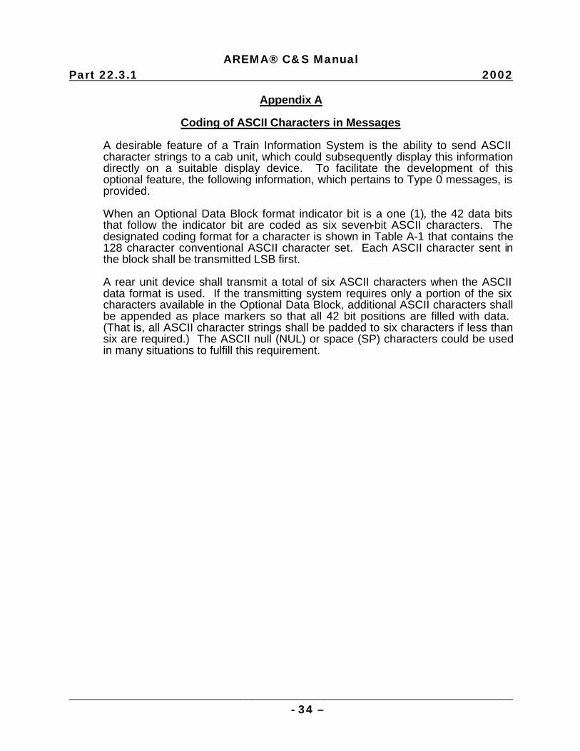
AREMA® C&S Manual
Part 22.3.1 2002
______________________________________________________________________________ - 34 –
Appendix A
Coding of ASCII Characters in Messages
A desirable feature of a Train Information System is the ability to send ASCII character strings to a cab unit, which could subsequently display this information directly on a suitable display device. To facilitate the development of this optional feature, the following information, which pertains to Type 0 messages, is provided.
When an Optional Data Block format indicator bit is a one (1), the 42 data bits that follow the indicator bit are coded as six seven-bit ASCII characters. The designated coding format for a character is shown in Table A-1 that contains the 128 character conventional ASCII character set. Each ASCII character sent in the block shall be transmitted LSB first.
A rear unit device shall transmit a total of six ASCII characters when the ASCII data format is used. If the transmitting system requires only a portion of the six characters available in the Optional Data Block, additional ASCII characters shall be appended as place markers so that all 42 bit positions are filled with data. (That is, all ASCII character strings shall be padded to six characters if less than six are required.) The ASCII null (NUL) or space (SP) characters could be used in many situations to fulfill this requirement.
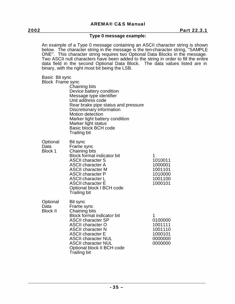
AREMA® C&S Manual
2002 Part 22.3.1
_____________________________________________________________________________ - 35 –
Type 0 message example: An example of a Type 0 message containing an ASCII character string is shown below. The character string in the message is the ten-character string, "SAMPLE ONE". This character string requires two Optional Data Blocks in the message. Two ASCII null characters have been added to the string in order to fill the entire data field in the second Optional Data Block. The data values listed are in binary, with the right most bit being the LSB.
Basic Bit sync Block Frame sync Chaining bits Device battery condition Message type identifier Unit address code Rear brake pipe status and pressure Discretionary information Motion detection Marker light battery condition Marker light status Basic block BCH code Trailing bit Optional Bit sync Data Frame sync Block 1 Chaining bits Block format indicator bit 1 ASCII character S 1010011 ASCII character A 1000001 ASCII character M 1001101 ASCII character P 1010000 ASCII character L 1001100 ASCII character E 1000101 Optional block I BCH code Trailing bit Optional Bit sync Data Frame sync Block II Chaining bits Block format indicator bit 1 ASCII character SP 0100000 ASCII character O 1001111 ASCII character N 1001110 ASCII character E 1000101 ASCII character NUL 0000000 ASCII character NUL 0000000 Optional block II BCH code Trailing bit

AREMA® C&S Manual
Part 22.3.1 2002
______________________________________________________________________________ - 36 –
Table 2231-A1: ASCII Code Chart
0
0 0
0
0 1
0
1 0
0
1 1
1
0 0
1
0 1
1
1 0
1
1 1
87
86 85 BITS
84 83 82 81
CONTROL HIGH X & Y
GRAPHIC INPUT LOW X LOW Y
0 0 0 0 NUL 0 DLE 16 SP 32 O 48 @ 68 P 80 ` 96 p 112
0 0 0 1 SOH 1 DC1 17 ! 33 1 49 A 65 Q 81 a 97 q 113
0 0 1 0 STX 2 DC2 18 " 34 2 50 B 66 R 82 b 98 r 114
0 0 1 1 EXT 3 DC3 19 # 35 3 51 C 67 S 83 c 99 s 115
0 1 0 0 EOT 4 DC4 20 $ 36 4 52 D 68 T 84 d 100 t 116
0 1 0 1 ENQ 5 NAK 21 % 37 5 53 E 69 U 85 e 101 u 117
0 1 1 0 ACK 6 SYN 22 & 38 6 54 F 70 V 86 f 102 v 118
0
1 1 1 BEL 7
BELL
ETB 23 ' 39 7 55 G 71 W 87 g 103 w 119
1 0 0 0 BS 8
BACK-
SPACE
CAN 24 ( 40 8 56 H 72 X 88 h 104 x 120
1 0 0 1 HT 9 EM 25 ) 41 9 57 I 73 Y 89 i 105 y 121
1 0 1 0 LF 10 SUB 26 * 42 : 58 J 74 Z 90 j 106 z 122
1 0 1 1 VT 11 ESC 27 + 43 ; 59 K 75 [ 91 k 107 { 123
1 1 0 0 FF 12 FS 28 , 44 < 60 L 76 \ 92 l 108 | 124
1 1 0 1 CR 13
RETURN
GS 29 - 45 = 61 M 77 ] 93 m 109 } 125
1 1 1 0 SO 14 RS 30 . 46 > 62 N 78 ^ 94 n 110 ~ 126
1 1 1 1 SI 15 US 31 / 47 ? 63 O 79 - 95 o 111 RUBOUT
(DEL) 127

AREMA® C&S Manual
2002 Part 22.3.1
_____________________________________________________________________________ - 37 –
Appendix B BIT POSITIONING DIAGRAM BASIC MESSAGE BLOCK - ONE WAY SYSTEM MSB LSB
UAC MESSAGE TYPE IDENTIFIER
DEVICE BATTERY CONDITION
CHAINING BITS
UNIT ADDRESS CODE (UAC)
UNIT ADDRESS CODE (UAC)
DISCRE- TIONARY
REAR BRAKE PIPE STATUS & PRESSURE
DISCRETIONARY INFORMATION
BCH CODE
MARKER STATUS
MARKER COND.
MOTION DETECT.
DISCRETIONARY INFORMATION
BCH CODE
TRAIL. BIT
BCH CODE
Note: Bit and Frame Sync Bits are not shown.
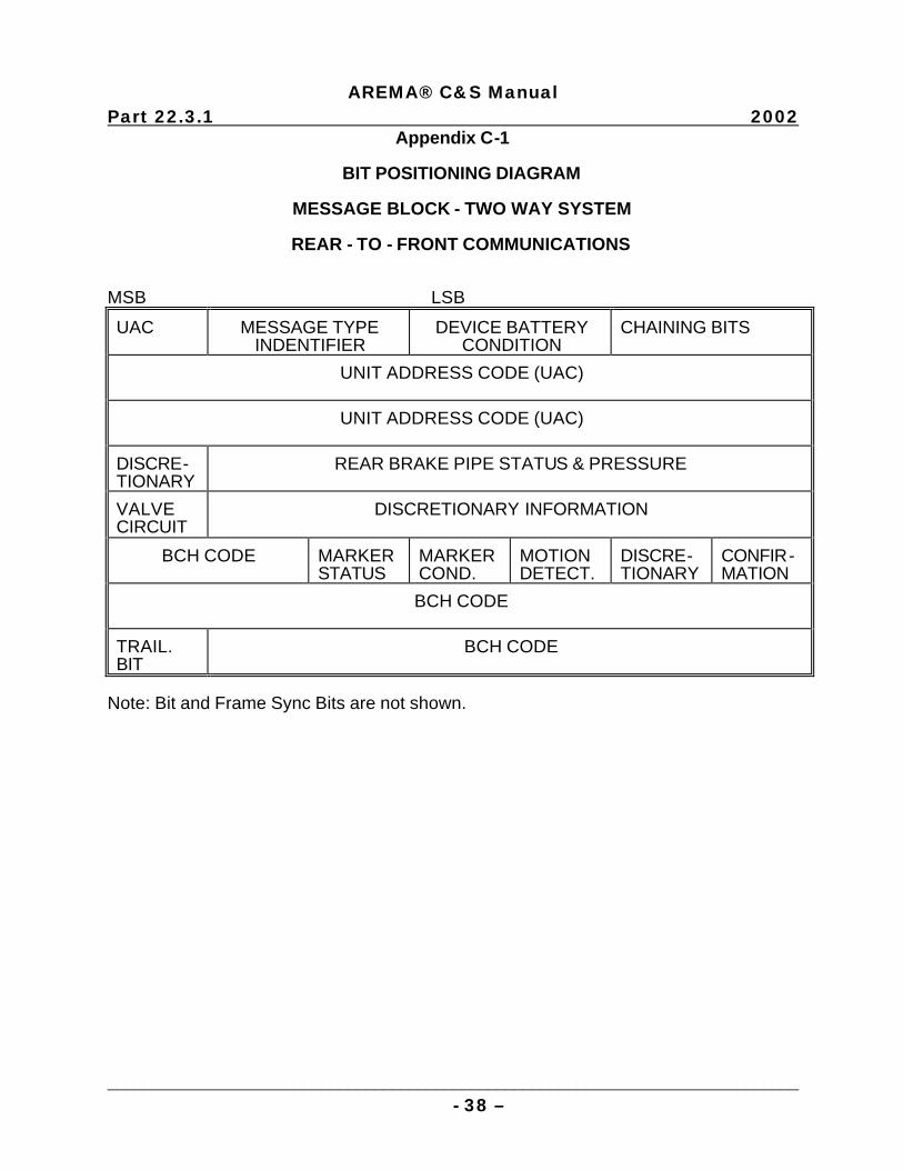
AREMA® C&S Manual
Part 22.3.1 2002
______________________________________________________________________________ - 38 –
Appendix C-1 BIT POSITIONING DIAGRAM MESSAGE BLOCK - TWO WAY SYSTEM REAR - TO - FRONT COMMUNICATIONS MSB LSB
UAC MESSAGE TYPE INDENTIFIER
DEVICE BATTERY CONDITION
CHAINING BITS
UNIT ADDRESS CODE (UAC)
UNIT ADDRESS CODE (UAC)
DISCRE- TIONARY
REAR BRAKE PIPE STATUS & PRESSURE
VALVE CIRCUIT
DISCRETIONARY INFORMATION
BCH CODE MARKER STATUS
MARKER COND.
MOTION DETECT.
DISCRE- TIONARY
CONFIR- MATION
BCH CODE
TRAIL. BIT
BCH CODE
Note: Bit and Frame Sync Bits are not shown.
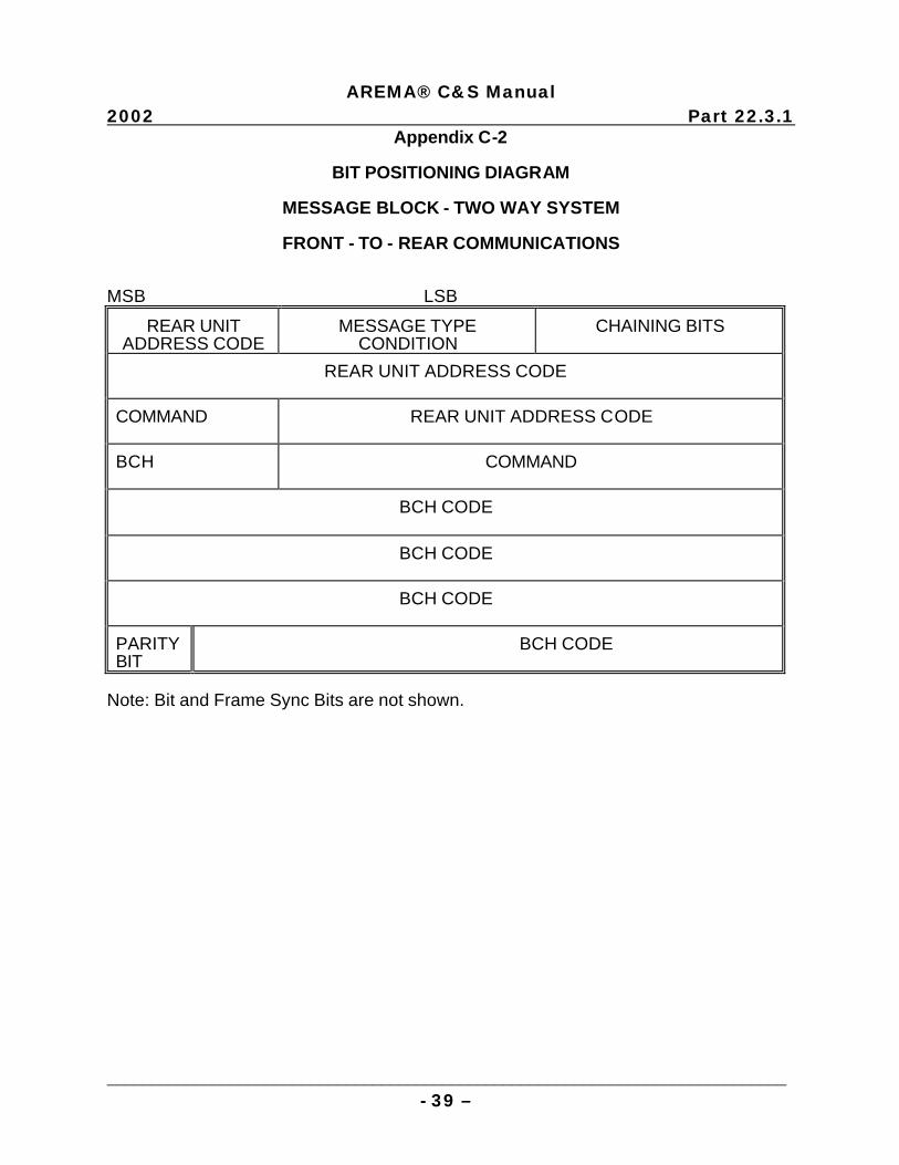
AREMA® C&S Manual
2002 Part 22.3.1
_____________________________________________________________________________ - 39 –
Appendix C-2
BIT POSITIONING DIAGRAM
MESSAGE BLOCK - TWO WAY SYSTEM
FRONT - TO - REAR COMMUNICATIONS MSB LSB
REAR UNIT ADDRESS CODE
MESSAGE TYPE CONDITION
CHAINING BITS
REAR UNIT ADDRESS CODE
COMMAND
REAR UNIT ADDRESS CODE
BCH COMMAND
BCH CODE
BCH CODE
BCH CODE
PARITY BIT
BCH CODE
Note: Bit and Frame Sync Bits are not shown.

This page intentionally left blank
Related Documents