1 Arduino Programming and Interfacing Stensat Group LLC, Copyright 2017

Welcome message from author
This document is posted to help you gain knowledge. Please leave a comment to let me know what you think about it! Share it to your friends and learn new things together.
Transcript

1
Arduino Programming and Interfacing
Stensat Group LLC, Copyright 2017

2
Robotic Arm Experimenters Kit

3
Legal Stuff
Stensat Group LLC assumes no responsibility and/or liability for the use of the kit and documentation.
There is a 90 day warranty for the kit against component defects. Damage caused by the user or owner is not covered.
Warranty does not cover such things as over tightening nuts on standoffs to the point of breaking off the standoff threads, breaking wires off the motors, causing shorts to damage components, powering the motor driver backwards, plugging the power input into an AC outlet, applying more than 9 volts to the power input, dropping the kit, kicking the kit, throwing the kit in fits of rage, unforeseen damage caused by the user/owner or any other method of destruction.
If you do cause damage, we can sell you replacement parts or you can get most replacement parts from online hardware distributors.
This document can be copied and printed and used by individuals who bought the kit, classroom use, summer camp use, and anywhere the kit is used. Stealing and using this document for profit is not allowed.
If you need to contact us, go to www.stensat.org and click on contact us.

44
Computer Boardand
Arduino Software
55
Parts of the Robotic Arm Kit
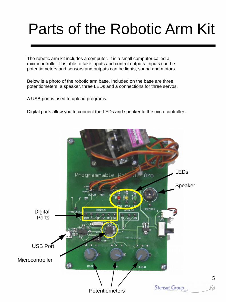
The robotic arm kit includes a computer. It is a small computer called a microcontroller. It is able to take inputs and control outputs. Inputs can be potentiometers and sensors and outputs can be lights, sound and motors.
Below is a photo of the robotic arm base. Included on the base are three potentiometers, a speaker, three LEDs and a connections for three servos.
A USB port is used to upload programs.
Digital ports allow you to connect the LEDs and speaker to the microcontroller.
Microcontroller
USB Port
LEDs
Speaker
Potentiometers
DigitalPorts

66
Using Arduino
This is the arduino software. The software will let you enter programs and upload the code to the processor board. It is called an Integrated Development Environment or IDE.
The large white area is where the code is entered. The black area below is where error messages will be displayed such as when there is an error in the code or the software cannot upload code for some reason.
The buttons below the menu have different functions. The first called Verify Code will compile the code and check for errors but not upload the code. The next button will do the same as the first but will also upload the code. New Program button opens a new copy of the program allowing you to start writing another program. Open and Save are for opening and saving the code you have written. Serial Monitor button opens a new window allowing you to interact with the processor. The Serial Monitor window allows the processor to display information and you to send information.
VerifyCode
UploadCode
NewProgram
OpenSave
SerialMonitor

77
Setting Up Arduino
To set up the kit with a computer, do the following:
1. Start the Arduino software.
2. Select the menu Tools and locate the item Board. A sub menu will open. Select Arduino Pro or Pro Mini.
3. Plug the kit into the computer. Let the computer load the device driver. If a device driver is not found, follow instructions at then end of this document.
4. Under the Tool menu, select Port and locate the COM port for the kit. It is usually COM 3 or higher. If more than one COM port show up. Select the higher number.
This completes the set up.

88
Program Development Sequence
There is a cycle to programming the processor board. First, you write code using instructions people can read. The instructions are called a computer language. Next, the code gets compiled which translates what you typed to machine code that the computer understands. Lastly, the code is executed by the computer. If there is an error, you change you code and start the process over.
Enter Code
Execute
Compile

99
First Program
Enter the program on the right in the editor. The compiler is case sensitive so pay attention to capitalized letters.
Turn on the kit using the power switch.
Click on the Upload Code button to compile and upload the program. It will ask you to save the program. Name it hello.
When the status message at the bottom of the window says done uploading, click on the Serial Monitor button. The Serial Monitor window pops up with the message being displayed.
Experiment by changing the message.
void setup(){ Serial.begin(9600);}
void loop(){ Serial.println(“Hello World”);}
Serial Monitor Window
UploadCode
SerialMonitor
1010
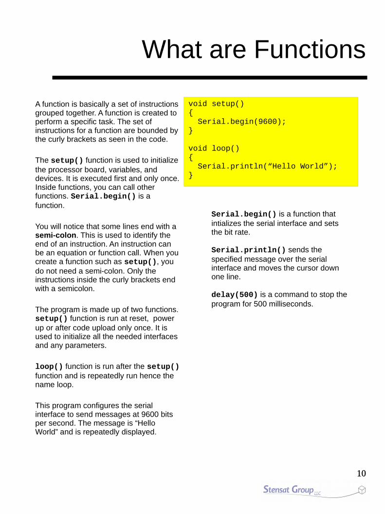
What are Functions
A function is basically a set of instructions grouped together. A function is created to perform a specific task. The set of instructions for a function are bounded by the curly brackets as seen in the code.
The setup() function is used to initialize the processor board, variables, and devices. It is executed first and only once. Inside functions, you can call other functions. Serial.begin() is a function.
You will notice that some lines end with a semi-colon. This is used to identify the end of an instruction. An instruction can be an equation or function call. When you create a function such as setup(), you do not need a semi-colon. Only the instructions inside the curly brackets end with a semicolon.
The program is made up of two functions. setup() function is run at reset, power up or after code upload only once. It is used to initialize all the needed interfaces and any parameters.
loop() function is run after the setup() function and is repeatedly run hence the name loop.
This program configures the serial interface to send messages at 9600 bits per second. The message is “Hello World” and is repeatedly displayed.
void setup(){ Serial.begin(9600);}
void loop(){ Serial.println(“Hello World”);}
Serial.begin() is a function that intializes the serial interface and sets the bit rate.
Serial.println() sends the specified message over the serial interface and moves the cursor down one line.
delay(500) is a command to stop the program for 500 milliseconds.

1111
What is in the Software
In the setup() function, it executes the function Serial.begin(9600). This function initializes the serial interface which is connected to the USB port to allow for communications. 9600 is the bit rate or how fast the data moves over the USB port. The data moves at 9,600 bits per second. The serial monitor window has its data rate that can be set and must match what Serial.begin() is set to.
In the loop() function, it executes the function Serial.print(“Hello world”). This function sends the text in quotes to the UART. This is displayed in the Serial Monitor window.
The other function is called delay(). This function stops the program for a specified period of time. The unit is in milliseconds. The code below displays the text every half second.
void setup(){
Serial.begin(9600);}
void loop(){
Serial.println(“Hello World”);delay(500);
}

1212
Turning on the Lights
Take a jumper wire and stick one end into D2 pin. Take the other end and connect it to LED1 pin as shown in the picture.
Open a new program and enter the code to the right. Click on the Upload Code button. You will be asked to save the program to a file. Pick a name like blinky and save. The software will then compile and upload the code.
The LED should start blinking.
void setup(){ pinMode(2,OUTPUT);}
void loop(){ digitalWrite(2,HIGH); delay(500); digitalWrite(2,LOW); delay(500);}

1313
How the Code WorksIn the setup() function, the function pinMode(2,OUTPUT) is used to configure the digital pin 2 to be an output so it can control the LED. You always need to configure the digital Pin to be an output when using it to control something like the LED.
In the loop() function, digital pin 2 is set high which causes the pin to generate 5 volts. The LED turns on. The delay() function halts the program for 500 milliseconds. The next digitalwrite() command sets digital pin 2 to 0 volts turning off the LED.
You can think of the digital pin as a light switch. It can be turned on and off. The computer language uses HIGH for the on state and LOW for the off state.
Experiment and change the delay settings to blink at different rates. How fast can you make the LED blink before you cannot see if blink?
What is an LED?
LED stands for Light Emitting Diode. It is a semiconductor device that generates light when an electric current passes through it. Current can only travel through the LED in one direction. In the wrong direction, the LED does not light up.
LEDs need the to current flowing through it limited otherwise it would pull a lot of current on its own and burn up. A resistor is used to reduce the current flowing through the LED. A resistor is a device that limits current flowing through a circuit. A circuit diagram to the right shows the LED connected to 5 volts.
The LED has an anode and a cathode. When the anode is at a higher voltage than the cathode, the LED will conduct current and light up. Do the reverse and the LED does not light up.
void setup(){
pinMode(2,OUTPUT);}
void loop(){
digitalWrite(2,HIGH);delay(500);digitalWrite(2,LOW);delay(500);
}
Anode
Cathode
Resistor
5V

1414
Two LEDs
Using the same blinky program, you will add a second LED. Connect D4 to LED 2, the yellow LED. Modify your blinky program to include the extra code in bold shown to the right.
Click on the Upload Code button. Once the program uploads, you should have the red and yellow LEDs blinking back and forth.
On your own, add the third LED. Pick a digital pin and connect it to the green LED.
Change the program to blink each LED in sequence.
void setup(){ pinMode(2,OUTPUT); pinMode(4,OUTPUT);}
void loop(){ digitalWrite(2,HIGH); digitalWrite(4,LOW); delay(500); digitalWrite(2,LOW); digitalWrite(4,HIGH); delay(500);}

1515
Make Sound
A speaker is a device that can make sounds. Connect digital pin D9 to the SPEAKER pin. Start a new program and enter the code below. To make a sound, you use the tone() function. The tone function takes two numbers, the digital pin number and the tone frequency. Try the program below and change the tone frequency. Pick a number between 40 and 5000.
void setup(){ pinMode(2,OUTPUT); pinMode(4,OUTPUT); pinMode(9,OUTPUT);}
void loop(){ digitalWrite(2,HIGH); digitalWrite(4,LOW); tone(9,2000); delay(500); digitalWrite(2,LOW); digitalWrite(4,HIGH); tone(9,1500); delay(500);}

1616
Musical Notes
Musical notes have specific frequencies. Since the tone() function uses frequency to set the pitch, you will need to translate notes to frequencies.
A C note has a frequency of 261 Hz. A D note has a frequency of 294 Hz.
In the code shown, there are these #define statements that are used to assign a value to a capital letter. These are not variables so they do not take up space. These are constants. Instead of entering numbers for tones, you can just enter the musical note. It makes the code more understandable. Try out the program. Add more notes and different delays.
#define C 161#define D 294#define E 329#define F 349#define G 392#define A 440#define B 493#define C2 523
void setup() { pinMode(9,OUTPUT);}
void loop() { tone(9,C); delay(500); tone(9,C2); delay(500);}
1717
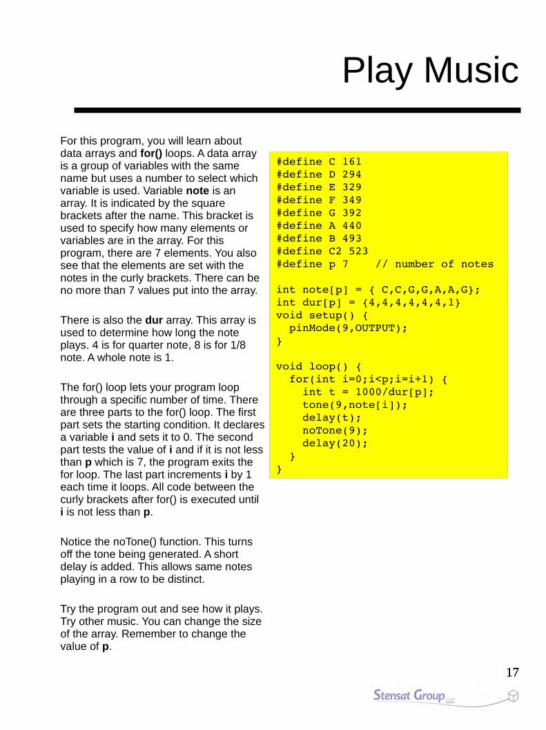
Play Music
For this program, you will learn about data arrays and for() loops. A data array is a group of variables with the same name but uses a number to select which variable is used. Variable note is an array. It is indicated by the square brackets after the name. This bracket is used to specify how many elements or variables are in the array. For this program, there are 7 elements. You also see that the elements are set with the notes in the curly brackets. There can be no more than 7 values put into the array.
There is also the dur array. This array is used to determine how long the note plays. 4 is for quarter note, 8 is for 1/8 note. A whole note is 1.
The for() loop lets your program loop through a specific number of time. There are three parts to the for() loop. The first part sets the starting condition. It declares a variable i and sets it to 0. The second part tests the value of i and if it is not less than p which is 7, the program exits the for loop. The last part increments i by 1 each time it loops. All code between the curly brackets after for() is executed until i is not less than p.
Notice the noTone() function. This turns off the tone being generated. A short delay is added. This allows same notes playing in a row to be distinct.
Try the program out and see how it plays. Try other music. You can change the size of the array. Remember to change the value of p.
#define C 161#define D 294#define E 329#define F 349#define G 392#define A 440#define B 493#define C2 523#define p 7 // number of notes
int note[p] = { C,C,G,G,A,A,G};int dur[p] = {4,4,4,4,4,4,1}void setup() { pinMode(9,OUTPUT);}
void loop() { for(int i=0;i<p;i=i+1) { int t = 1000/dur[p]; tone(9,note[i]); delay(t); noTone(9); delay(20); }}

1818
Push Button
This experiment triggers the sound when the button is pressed. When the button is released, the tone continues for two seconds.
Use a jumper wire and connect it to the BUTTON and digital pin D10.
Open a new program and enter the code to the right. Once completed, click on the Upload Code button. Enter the file name alarm.
void setup(){ pinMode(10,INPUT); pinMode(9,OUTPUT);}
void loop(){ int a; a = digitalRead(10); if(a == 0) { tone(9,2000,1000); tone(9,1000,2000); }}
How it works:
A push button is also known as a momentary switch. It only closes its contact with pressed. Closing the contacts completes the electrical circuit. For this circuit, the digital pin D10 sees 5 volts. When the push button is pressed, D10 sees 0 volts. 0 volts is represented as value zero. 5 volts is represented as one.The function digitalRead() returns a one or a zero depending on the voltage on pin D10. If the variable a is set to zero, the button is pressed. If the variable a is set to one, the button is not pressed.

1919
How a Potentiometer WorksThe potentiometer is a resistor device with a wiper that can contact any part of the resistor. The wiper will have a different resistance based on where it is making contact. Contact X is connected to the negative side of a power source which is zero volts. Contact Z is connected to the positive side of a power source. Contact Y, which connects to the wiper, will have a voltage in between the negative and positive side of the power source. The closer the wiper is to X, the closer to zero volts. The closer the wiper is to Y the more positive the voltage.
Potentiometers are useful for many things. They are used for volume control on radios or other audio devices. For the robotic arm kit, the potentiometer will be used to set the position of the parts of the arm.
On the robotic arm kit, each potentiometer has its X contact connected to zero volts and the Z contact connected to 5 volts. As you adjust the potentiometer knob, the voltage at Y will vary between 0 and 5 volts.
ResistiveStrip
Wiper
X Y Z

2020
Measuring the Potentiometers
The program to the right introduces a new function called analogRead(). The three potentiometers are connected to three analog input ports. Base is analog port 0. Arm is analog port 1. Elbow is analog port 2.
Start a new program and enter the code. When it is uploaded, open the serial monitor. Adjust the BASE knob and see how the number in the first column changes. You should see that the numbers range from 0 to 1023. Adjust the other knobs and see their respective columns change values.
The analog converter converts a voltage to a number. 0 is the lowest voltage and 1023 is the highest voltage which is 5 volts.
A variable is a memory location for storing a piece of data. Variables are given names. This lets the memory location to be easily used when writing a program. You have to tell the computer you want to store data by declaring a variable. You can declare many variables. Each one needs a unique name. In this program, three variables are declared as int. int stands for integer which means whole number.
void setup(){ Serial.begin(9600);}
void loop(){ int a; int b,c; a = analogRead(0); b = analogRead(1); c = analogRead(2); Serial.print(a); Serial.print(“ “); Serial.print(b); Serial.print(“ “); Serial.println(c); delay(200);}

2121
Using the Inputs to Control Outputs
Next is to use the potentiometer to control something. This example will use the potentiometer to control the tone going to the speaker. Connect a jumper from D9 to the SPEAKER.
Start a new program and enter the code to the right and click on the Upload Code button. Turn the BASE knob and the tone should change pitch.
void setup(){ pinMode(9,OUTPUT);}
void loop() { int a = analogRead(0); int b = map(a,0,1023,100,1000); tone(9,b);}
There is a new function to learn called map(). It converts one range of number to another range. It is like scaling. Since the analog port can generate a range of numbers from 0 to 1023, the input range of the map() function is set to that. The output range is set to whatever you want. The example shows 100 Hz to 1000 Hz. It can be a different range like 30 to 5000. Experiment with different ranges.
b = map(a,c,d,y,z);
b is the result from the map function.a is the variable being converted.c is the low end that a can go.d is the high end that a can go.y is the new low end.z is the new high end.
2222
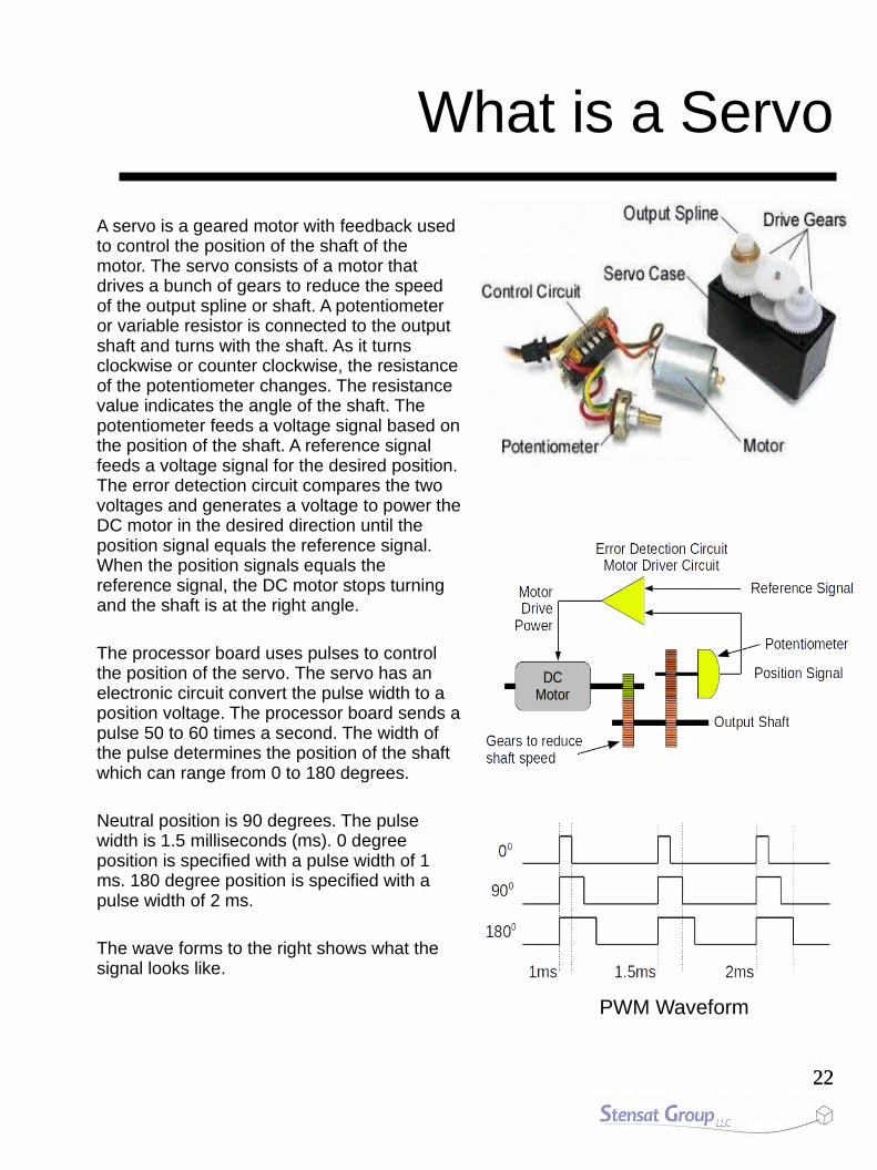
What is a Servo
A servo is a geared motor with feedback used to control the position of the shaft of the motor. The servo consists of a motor that drives a bunch of gears to reduce the speed of the output spline or shaft. A potentiometer or variable resistor is connected to the output shaft and turns with the shaft. As it turns clockwise or counter clockwise, the resistance of the potentiometer changes. The resistance value indicates the angle of the shaft. The potentiometer feeds a voltage signal based on the position of the shaft. A reference signal feeds a voltage signal for the desired position. The error detection circuit compares the two voltages and generates a voltage to power the DC motor in the desired direction until the position signal equals the reference signal. When the position signals equals the reference signal, the DC motor stops turning and the shaft is at the right angle.
The processor board uses pulses to control the position of the servo. The servo has an electronic circuit convert the pulse width to a position voltage. The processor board sends a pulse 50 to 60 times a second. The width of the pulse determines the position of the shaft which can range from 0 to 180 degrees.
Neutral position is 90 degrees. The pulse width is 1.5 milliseconds (ms). 0 degree position is specified with a pulse width of 1 ms. 180 degree position is specified with a pulse width of 2 ms.
The wave forms to the right shows what the signal looks like.
PWM Waveform

2323
Programming the Arm
The diagram to the right shows the potentiometers connected to the computer board along with the servos.
The servos are connected to digital pins number 3, 5 and 6. The potentiometers are connected to the analog ports 0,1 and 2.
The program needs to operate in a specific sequence. It must first measure the state of the potentiometers. Second, it must calculate the servo angles and finally set the servo angles. This sequence is repeated.
ComputerComputer
Servos
Potentiometers
D3 D5 D6
A0 A1 A2
MeasurePotentiometers
CalculateServoAngles
UpdateServoAngles
Program Flow Chart

2424
Programming the ArmOn to the software, a library needs to be added. A library is a file that contains a collection of useful functions. You will need to include the servo library which has functions to control the robotic arm servos.
Click on the menu Sketch and select Include Library. Locate the Servo library in the list and select it. An include statement is inserted at the top of the program. This tells the compiler to include that library.
Next, three servos need to be defined. the base servo will let you control the servo at the bottom and rotate the arm left and right. The arm servo will control the second servo that moves the arm up and down. The third servo controls the elbow that allows the arm to extend.
In the setup() function, the attach() functions assign each servo to a digital port. Notice the servo name is in front of the attach() function separated by a period. This is object oriented programming. Any servo function can be performed by including the name of the servo in front of the function with the period in between.
In the loop() function, the three potentiometers are measured using the analogRead() functions. Next, the calculation to convert the range of the potentiometers to the servos is performed using the map() function. Lastly, the servo positions are updated using the write() function. Again, notice that the servo names are used with the write() function.
#include <Servo.h>
Servo base;Servo arm;Servo elbow;
void setup() { base.attach(3); arm.attach(5); elbow.attach(6); Serial.begin(9600);}
void loop() { int b = analogRead(0); int a = analogRead(1); int e = analogRead(2); b = map(b,0,1023,179,1); a = map(a,0,1023,1,80); e = map(e,0,1023,1,179); base.write(b); arm.write(a); elbow.write(e);}

2525
End

2626
Loading and Configuring Arduino Software
● Download the latest Arduino software from www.arduino.cc
● It can be installed anywhere on the computer.
● Open the folder and double click Arduino.
● The first step is to select the correct processor. Arduino software supports many different variations.
● In the arduino program select menu “Tools”
● Select “Board”
● Select “Arduino Pro or Pro Mini” at or near the top of the menu.
● Go back and select “Processor” under the “Tools” menu.
● Select “Atmega328 (5V, 16MHz)”

2727
Configuring Arduino Software
● Plug the processor board into the computer USB port
● Let the operating system find the drivers. (network connection required)
– The driver is also included with arduino software
● In the arduino program select menu “Tools”
● Select “serial Port”
● Select the appropriate COM port.
– If you have a modem built in or existing COM ports, the COM number for the processor will usually be the highest number.
● Next two pages describe how to install the drivers if needed.

2828
Windows COM Port
● If the Serial Port menu does not show any COM ports try the following:
● Go to http://www.ftdichip.com/Drivers/VCP.htm
● In the table on the website, locate the row specifying Windows.
● Click on the link setup executable and download the software.
● Right click on the icon labeled CDM v2.12.00..... and select Run as Administrator in the menu that pops up.
● Follow the instructions to install. You have to run the installation program as an administrator or the driver will not install.
● Go back to Arduino and select the COM Port it gives you.
● Most likely, the COM port will be COM3. If there is more than one COM port, choose the higher number.

2929
Macintosh OS X USB Driver Installation
● Go to http://www.ftdichip.com/Drivers/VCP.htm
● Select VCP driver (Virtual COM Port) for Mac .
● Pick the driver for the version of MAC OSX.
● Download and double click on the file.
● A window will open showing two packages.
● Double click the package for the OS version you have.
● Follow instructions for the installation.
● Go back to Arduino and select the Serial Port: /dev/tty.usbserial-Daxxxxxx.
● The xxxxxx will be some combination of letters and numbers.
● If it is not seen, reboot the mac. Make sure the processor board is plugged into the mac using the USB cable.
Related Documents