Page | 1 Ardenna Payload Requirements Version 1.0 Ardenna Proprietary March 9, 2021

Welcome message from author
This document is posted to help you gain knowledge. Please leave a comment to let me know what you think about it! Share it to your friends and learn new things together.
Transcript
P a g e | 1
Ardenna
Payload Requirements
Version 1.0
Ardenna Proprietary
March 9, 2021
ARDENNA PROPRIETARY P a g e | 2
TABLE OF CONTENTS Table of Contents ........................................................................................................................................ 2
Output File Formats ..................................................................................................................................... 4
Overview .................................................................................................................................................. 4
Files and Folders ...................................................................................................................................... 4
Folder Naming ..................................................................................................................................... 4
Image/Lidar/Metadata File Naming .................................................................................................... 5
Image file format and EXIF/XMP headers ............................................................................................ 5
MetaData File Format .......................................................................................................................... 7
Lidar Binary File Format ....................................................................................................................... 7
String Binary Data ............................................................................................................................ 9
Matrix Binary Data ........................................................................................................................... 9
Vector Binary Data ........................................................................................................................... 9
Flight Planning ........................................................................................................................................... 10
Overview ................................................................................................................................................ 10
Oblique Angle ........................................................................................................................................ 10
Flight Sequence ..................................................................................................................................... 11
Example Sequence For A 6 Track Yard ................................................................................................... 11
Pass Number 1 (Starting Pass) ........................................................................................................... 11
Pass Number 2 ................................................................................................................................... 11
Pass Number 3 ................................................................................................................................... 11
Pass Number 4 ................................................................................................................................... 12
Pass Number 5 ................................................................................................................................... 12
Pass Number 6 ................................................................................................................................... 12
Pass Number 7 ................................................................................................................................... 13
Pass Number 8 ................................................................................................................................... 13
Pass Number 9 ................................................................................................................................... 13
Pass Number 10 ................................................................................................................................. 14
Pass Number 11 (Final Pass) .............................................................................................................. 14
GSD and Trigger Distance .......................................................................................................................... 14
Overview ................................................................................................................................................ 14
How is GSD Computed ........................................................................................................................... 15
GSD Requirements ................................................................................................................................. 15
ARDENNA PROPRIETARY P a g e | 3
GSD in Oblique Passes ........................................................................................................................... 15
Triggering Distance ................................................................................................................................ 16
Camera And Lidar Mounting ...................................................................................................................... 17
Overview ................................................................................................................................................ 17
Camera Mounting .................................................................................................................................. 17
Lidar Mounting ...................................................................................................................................... 18
Camera And Lidar Pointing (IMU) .............................................................................................................. 18
Overview ................................................................................................................................................ 18
IMU Axis Convention ............................................................................................................................. 18
Camera Mounting Orientation .............................................................................................................. 20
Lidar Mounting Orientation ................................................................................................................... 21
Camera Calibration .................................................................................................................................... 21
ARDENNA PROPRIETARY P a g e | 4
OUTPUT FILE FORMATS OVERVIEW This section describes in detail the various different files to be produced and their formats
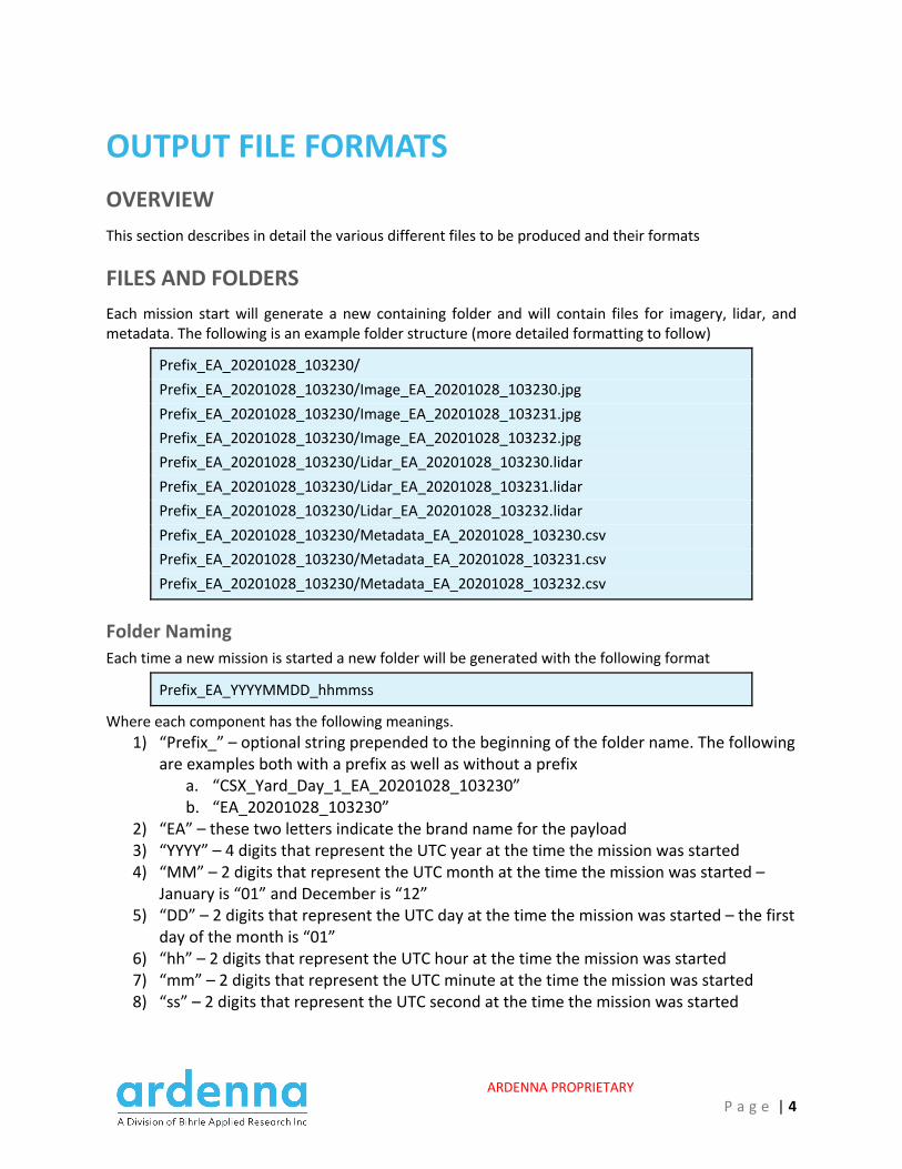
FILES AND FOLDERS Each mission start will generate a new containing folder and will contain files for imagery, lidar, and metadata. The following is an example folder structure (more detailed formatting to follow)
Prefix_EA_20201028_103230/ Prefix_EA_20201028_103230/Image_EA_20201028_103230.jpg Prefix_EA_20201028_103230/Image_EA_20201028_103231.jpg Prefix_EA_20201028_103230/Image_EA_20201028_103232.jpg Prefix_EA_20201028_103230/Lidar_EA_20201028_103230.lidar Prefix_EA_20201028_103230/Lidar_EA_20201028_103231.lidar Prefix_EA_20201028_103230/Lidar_EA_20201028_103232.lidar Prefix_EA_20201028_103230/Metadata_EA_20201028_103230.csv Prefix_EA_20201028_103230/Metadata_EA_20201028_103231.csv Prefix_EA_20201028_103230/Metadata_EA_20201028_103232.csv
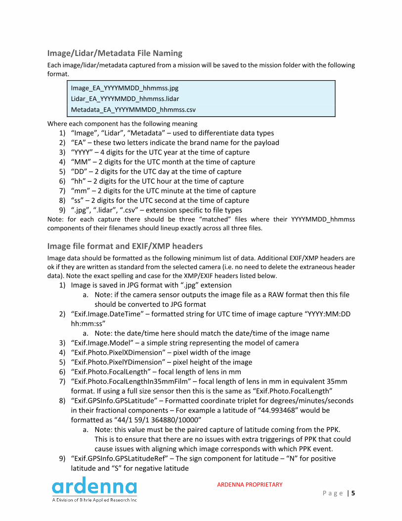
Folder Naming Each time a new mission is started a new folder will be generated with the following format
Prefix_EA_YYYYMMDD_hhmmss
Where each component has the following meanings. 1) “Prefix_” – optional string prepended to the beginning of the folder name. The following
are examples both with a prefix as well as without a prefix a. “CSX_Yard_Day_1_EA_20201028_103230” b. “EA_20201028_103230”
2) “EA” – these two letters indicate the brand name for the payload 3) “YYYY” – 4 digits that represent the UTC year at the time the mission was started 4) “MM” – 2 digits that represent the UTC month at the time the mission was started –
January is “01” and December is “12” 5) “DD” – 2 digits that represent the UTC day at the time the mission was started – the first
day of the month is “01” 6) “hh” – 2 digits that represent the UTC hour at the time the mission was started 7) “mm” – 2 digits that represent the UTC minute at the time the mission was started 8) “ss” – 2 digits that represent the UTC second at the time the mission was started
ARDENNA PROPRIETARY P a g e | 5
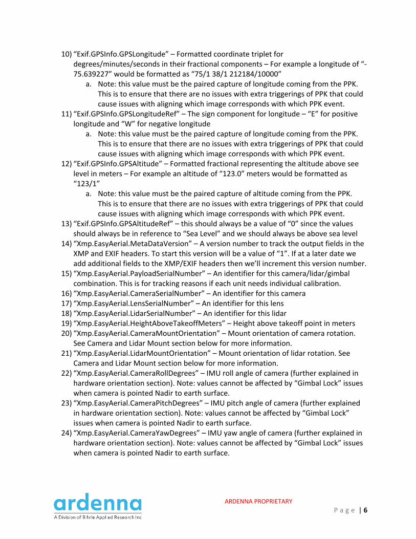
Image/Lidar/Metadata File Naming Each image/lidar/metadata captured from a mission will be saved to the mission folder with the following format.
Image_EA_YYYYMMDD_hhmmss.jpg Lidar_EA_YYYYMMDD_hhmmss.lidar Metadata_EA_YYYYMMMDD_hhmmss.csv
Where each component has the following meaning 1) “Image”, “Lidar”, “Metadata” – used to differentiate data types 2) “EA” – these two letters indicate the brand name for the payload 3) “YYYY” – 4 digits for the UTC year at the time of capture 4) “MM” – 2 digits for the UTC month at the time of capture 5) “DD” – 2 digits for the UTC day at the time of capture 6) “hh” – 2 digits for the UTC hour at the time of capture 7) “mm” – 2 digits for the UTC minute at the time of capture 8) “ss” – 2 digits for the UTC second at the time of capture 9) “.jpg”, “.lidar”, “.csv” – extension specific to file types
Note: for each capture there should be three “matched” files where their YYYYMMDD_hhmmss components of their filenames should lineup exactly across all three files.
Image file format and EXIF/XMP headers Image data should be formatted as the following minimum list of data. Additional EXIF/XMP headers are ok if they are written as standard from the selected camera (i.e. no need to delete the extraneous header data). Note the exact spelling and case for the XMP/EXIF headers listed below.
1) Image is saved in JPG format with “.jpg” extension a. Note: if the camera sensor outputs the image file as a RAW format then this file
should be converted to JPG format 2) “Exif.Image.DateTime” – formatted string for UTC time of image capture “YYYY:MM:DD
hh:mm:ss” a. Note: the date/time here should match the date/time of the image name
3) “Exif.Image.Model” – a simple string representing the model of camera 4) “Exif.Photo.PixelXDimension” – pixel width of the image 5) “Exif.Photo.PixelYDimension” – pixel height of the image 6) “Exif.Photo.FocalLength” – focal length of lens in mm 7) “Exif.Photo.FocalLengthIn35mmFilm” – focal length of lens in mm in equivalent 35mm
format. If using a full size sensor then this is the same as “Exif.Photo.FocalLength” 8) “Exif.GPSInfo.GPSLatitude” – Formatted coordinate triplet for degrees/minutes/seconds
in their fractional components – For example a latitude of “44.993468” would be formatted as “44/1 59/1 364880/10000”
a. Note: this value must be the paired capture of latitude coming from the PPK. This is to ensure that there are no issues with extra triggerings of PPK that could cause issues with aligning which image corresponds with which PPK event.
9) “Exif.GPSInfo.GPSLatitudeRef” – The sign component for latitude – “N” for positive latitude and “S” for negative latitude
ARDENNA PROPRIETARY P a g e | 6
10) “Exif.GPSInfo.GPSLongitude” – Formatted coordinate triplet for degrees/minutes/seconds in their fractional components – For example a longitude of “-75.639227” would be formatted as “75/1 38/1 212184/10000”
a. Note: this value must be the paired capture of longitude coming from the PPK. This is to ensure that there are no issues with extra triggerings of PPK that could cause issues with aligning which image corresponds with which PPK event.
11) “Exif.GPSInfo.GPSLongitudeRef” – The sign component for longitude – “E” for positive longitude and “W” for negative longitude
a. Note: this value must be the paired capture of longitude coming from the PPK. This is to ensure that there are no issues with extra triggerings of PPK that could cause issues with aligning which image corresponds with which PPK event.
12) “Exif.GPSInfo.GPSAltitude” – Formatted fractional representing the altitude above see level in meters – For example an altitude of “123.0” meters would be formatted as “123/1”
a. Note: this value must be the paired capture of altitude coming from the PPK. This is to ensure that there are no issues with extra triggerings of PPK that could cause issues with aligning which image corresponds with which PPK event.
13) “Exif.GPSInfo.GPSAltitudeRef” – this should always be a value of “0” since the values should always be in reference to “Sea Level” and we should always be above sea level
14) “Xmp.EasyAerial.MetaDataVersion” – A version number to track the output fields in the XMP and EXIF headers. To start this version will be a value of “1”. If at a later date we add additional fields to the XMP/EXIF headers then we’ll increment this version number.
15) “Xmp.EasyAerial.PayloadSerialNumber” – An identifier for this camera/lidar/gimbal combination. This is for tracking reasons if each unit needs individual calibration.
16) “Xmp.EasyAerial.CameraSerialNumber” – An identifier for this camera 17) “Xmp.EasyAerial.LensSerialNumber” – An identifier for this lens 18) “Xmp.EasyAerial.LidarSerialNumber” – An identifier for this lidar 19) “Xmp.EasyAerial.HeightAboveTakeoffMeters” – Height above takeoff point in meters 20) “Xmp.EasyAerial.CameraMountOrientation” – Mount orientation of camera rotation.
See Camera and Lidar Mount section below for more information. 21) “Xmp.EasyAerial.LidarMountOrientation” – Mount orientation of lidar rotation. See
Camera and Lidar Mount section below for more information. 22) “Xmp.EasyAerial.CameraRollDegrees” – IMU roll angle of camera (further explained in
hardware orientation section). Note: values cannot be affected by “Gimbal Lock” issues when camera is pointed Nadir to earth surface.
23) “Xmp.EasyAerial.CameraPitchDegrees” – IMU pitch angle of camera (further explained in hardware orientation section). Note: values cannot be affected by “Gimbal Lock” issues when camera is pointed Nadir to earth surface.
24) “Xmp.EasyAerial.CameraYawDegrees” – IMU yaw angle of camera (further explained in hardware orientation section). Note: values cannot be affected by “Gimbal Lock” issues when camera is pointed Nadir to earth surface.
ARDENNA PROPRIETARY P a g e | 7
MetaData File Format All data described in the above EXIF/XMP header section is also to be placed in a simple csv metadata file. Listed below are the column names for this file.
1) “MetaDataVersion” – same as “Xmp.EasyAerial. MetaDataVersion” above 2) “DateTime” – same as “Exif.Image.DateTime” above 3) “CameraModel” – same as “Exif.Image.Model” above 4) “PixelXDimension” – same as “Exif.Photo.PixelXDimension” above 5) “PixelYDimension” – same as “Exif.Photo.PixelYDimension” above 6) “FocalLength(mm)” – same as “Exif.Photo.FocalLength” above 7) “FocalLength35mmFilm” – same as “Exif.Photo.FocalLengthIn35mmFilm” above 8) “Latitude(deg)” – signed number for latitude in degrees with at least 7 significant
decimal places. a. Note: value must be the paired capture of Latitude from the PPK
9) “Longitude(deg)” – signed number for longitude in degrees with at least 7 significant decimal places.
a. Note: value must be the paired capture of Longitude from the PPK 10) “Altitude(m)” – altitude in meters referenced to sea level
a. Note: value must be the paired capture of Altitude from the PPK 11) “HeightAboveTakeoff(m)” – altitude in meters referenced to the takeoff point 12) “PayloadSerialNumber” – same as “Xmp.EasyAerial. PayloadSerialNumber” above 13) “CameraSerialNumber” – same as “Xmp.EasyAerial.CameraSerialNumber” above 14) “LensSerialNumber” – same as “Xmp.EasyAerial.LensSerialNumber” above 15) “LidarSerialNumber” – same as “Xmp.EasyAerial. LidarSerialNumber” above 16) “CameraMountOrientation(deg)” – same as “Xmp.EasyAerial.CameraMountOrientation”
above 17) “LidarMountOrientation(deg)” – same as “Xmp.EasyAerial.LidarMountOrientation”
above 18) “CameraRoll(deg)” – same as “Xmp.EasyAerial.CameraRollDegrees” above 19) “CameraPitch(deg)” – same as “Xmp.EasyAerial.CameraPitchDegrees” above 20) “CameraYaw(deg)” – same as “Xmp.EasyAerial.CameraYawDegrees” above
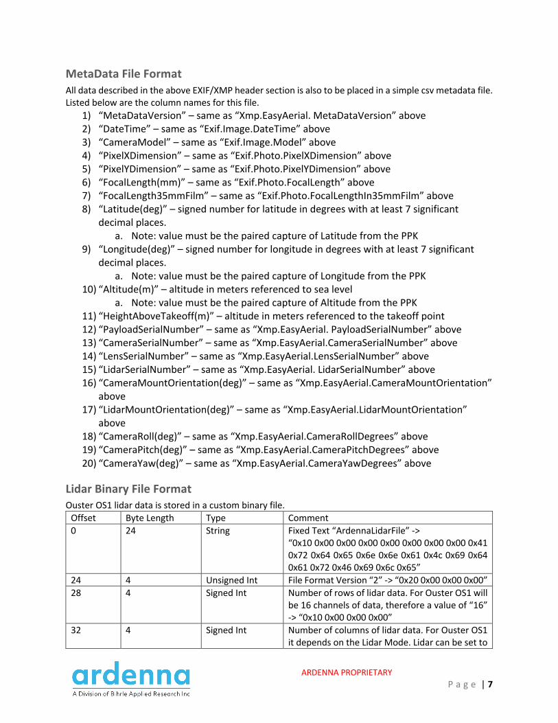
Lidar Binary File Format Ouster OS1 lidar data is stored in a custom binary file.
Offset Byte Length Type Comment 0 24 String Fixed Text “ArdennaLidarFile” ->
“0x10 0x00 0x00 0x00 0x00 0x00 0x00 0x00 0x41 0x72 0x64 0x65 0x6e 0x6e 0x61 0x4c 0x69 0x64 0x61 0x72 0x46 0x69 0x6c 0x65”
24 4 Unsigned Int File Format Version “2” -> “0x20 0x00 0x00 0x00” 28 4 Signed Int Number of rows of lidar data. For Ouster OS1 will
be 16 channels of data, therefore a value of “16” -> “0x10 0x00 0x00 0x00”
32 4 Signed Int Number of columns of lidar data. For Ouster OS1 it depends on the Lidar Mode. Lidar can be set to

ARDENNA PROPRIETARY P a g e | 8
capture 512, 1024, or 2048 lidar points per revolution. Lidar should be set to capture 2048 points every revolution then -> “0x00 0x08 0x00 0x00”
36 2 Unsigned Short Lidar Frame ID. This value will increment every revolution of the laser motor.
38 131,084 Matrix<Signed Int>
Matrix of lidar range data. So if the lidar has 16 rows and 2048 columns then the matrix will have 16 rows and 2048 columns of data. The range data is in units of millimeters and is stored in a “Signed Int” object.
131122 65,548 Matrix<Unsigned Short>
Matrix of lidar reflectivity data. So if the lidar has 16 rows and 2048 columns then the matrix will have 16 rows and 2048 columns of data. The reflectivity data is stored in an “Unsigned Short” object.
196,670 65,548 Matrix<Unsigned Short>
Matrix of lidar signal photon data. So if the lidar has 16 rows and 2048 columns then the matrix will have 16 rows and 2048 columns of data. The signal photon data is stored in an “Unsigned Short” object.
262,218 131,084 Matrix<Signed Int>
Matrix of lidar noise photon data. So if the lidar has 16 rows and 2048 columns of data the matrix will have 16 rows and 2048 columns of data. The noise photon data is stored in a “Signed Int” object.
393,302 16,392 Vector<Double> Vector of encoder counts by data column. So if the lidar has 2048 columns of data then this vector will have 2048 elements of encoder data.
409,694 136 Vector<Double> Vector of beam altitude angles by row. So if the lidar has 16 rows of data then this vector will have 16 elements of altitude angles. Values for beam altitudes given in units of degrees. Beam altitudes can be queried directly from the lidar using the Get_Beam_Intrinsics command.
409,830 136 Vector<Double> Beam Azimuth Angle Offsets by Row. So if the lidar has 16 rows of data then this vector will have 16 elements of azimuth angle offsets. Values for azimuth offsets given in units of degrees. Azimuth offsets can be queried directly from the lidar using the Get_Beam_Intrinisics command.
409,966 Variable Length String Raw Configuration JSON String obtained by directly querying the lidar using the Get_Config_Txt command
Variable Length String Raw Sensor Info JSON String obtained by directly querying the lidar using the Get_Sensor_Info command

ARDENNA PROPRIETARY P a g e | 9
Variable Length String Raw Beam Intrinsics JSON String obtained by directly querying the lidar using the Get_Beam_Intrinsics command
String Binary Data
Offset Byte Length Type Comment 0 8 Unsigned Long String length. For Example, If String is
“ArdennaLidarFile”, then string length is 16 -> “0x10 0x00 0x00 0x00 0x00 0x00 0x00 0x00”
8 Length of String Unsigned Char String Data. For Example, If String is “ArdennaLidarFile” then binary data is “
Matrix Binary Data
Offset Byte Length Type Comment 0 4 Signed Int Matrix data type
1) Unsigned Int -> 2 -> “0x02 0x00 0x00 0x00”
2) Signed Int -> 4 -> “0x04 0x00 0x00 0x00”
4 4 Signed Int Matrix Column Count. For Example, 2048 -> “0x00 0x08 0x00 0x00”
8 4 Signed Int Matrix Row Count. For Example, 16 -> “0x10 0x00 0x00 0x00”
12 Rows * Cols * ElemSize
Matrix of Elements
If Matrix has type “Unsigned Int” and row count of “16” and column count of “2048” then there will be 4*16*2048=131,072 bytes of matrix data. Data is saved by row, meaning that row1 is saved first then row2, then row3, etc…
Vector Binary Data
Offset Byte Length Type Comment 0 8 Unsigned Long Vector length. For example if the vector has a
length of 2048 elements -> “0x00 0x08 0x00 0x00”
8 Size * ElemSize Array of Elements If Vector has type “Double” and length “2048” then there will be 8*2048=16,384 bytes of vector data

ARDENNA PROPRIETARY P a g e | 10
FLIGHT PLANNING OVERVIEW Proper flight planning will be critical to ensure enough of the right imagery is captured so that all of Ardenna’s AI software can make as many detections as possible. At a high level, flight planning is comprised of a series of Nadir flights (Nadir means the camera is pointed straight down at the ground) and Oblique flights (Oblique means the drone is offset from the tracks with the camera pointed back at the track from an angle)
OBLIQUE ANGLE The oblique angle is the angle the drone is offset from the tracks so that Joint Bars can be captured in imagery. Unless changed in the future the Oblique angle should always be planned for 30 degrees off of Nadir and is shown in the graphic below. Also note that in the oblique passes (as shown in the graphic) that the altitude of the drone has decreased slightly. This will be explained a little more in the GSD section.
ARDENNA PROPRIETARY P a g e | 11
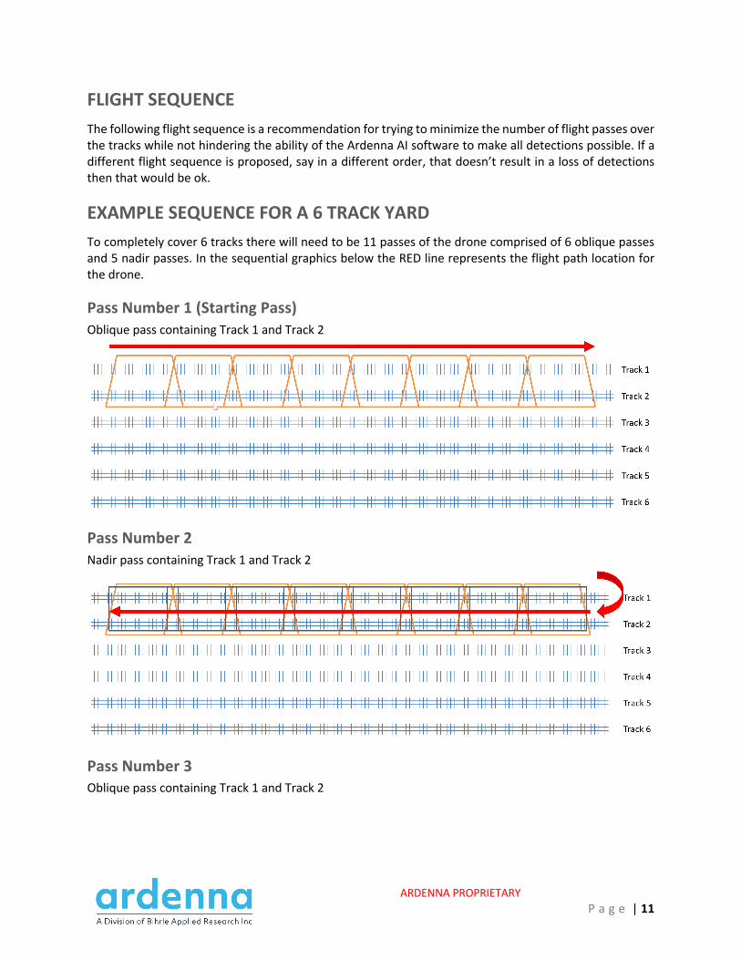
FLIGHT SEQUENCE The following flight sequence is a recommendation for trying to minimize the number of flight passes over the tracks while not hindering the ability of the Ardenna AI software to make all detections possible. If a different flight sequence is proposed, say in a different order, that doesn’t result in a loss of detections then that would be ok.
EXAMPLE SEQUENCE FOR A 6 TRACK YARD To completely cover 6 tracks there will need to be 11 passes of the drone comprised of 6 oblique passes and 5 nadir passes. In the sequential graphics below the RED line represents the flight path location for the drone.
Pass Number 1 (Starting Pass) Oblique pass containing Track 1 and Track 2
Pass Number 2 Nadir pass containing Track 1 and Track 2
Pass Number 3 Oblique pass containing Track 1 and Track 2
ARDENNA PROPRIETARY P a g e | 12
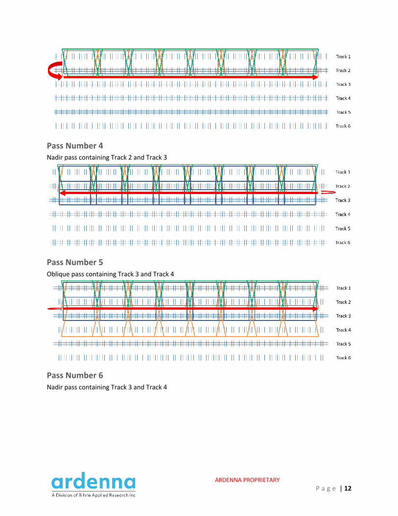
Pass Number 4 Nadir pass containing Track 2 and Track 3
Pass Number 5 Oblique pass containing Track 3 and Track 4
Pass Number 6 Nadir pass containing Track 3 and Track 4

ARDENNA PROPRIETARY P a g e | 13
Pass Number 7 Oblique pass containing Track 3 and Track 4
Pass Number 8 Nadir pass containing Track 4 and Track 5
Pass Number 9 Oblique pass containing Track 5 and Track 6
ARDENNA PROPRIETARY P a g e | 14
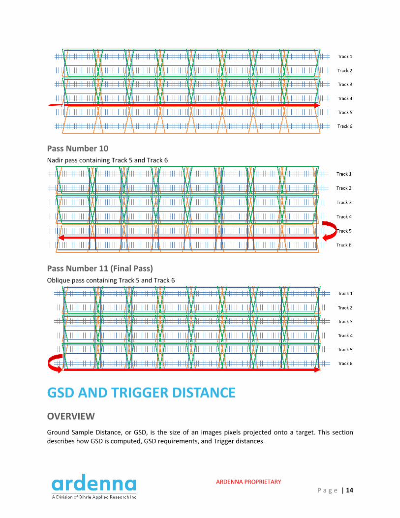
Pass Number 10 Nadir pass containing Track 5 and Track 6
Pass Number 11 (Final Pass) Oblique pass containing Track 5 and Track 6
GSD AND TRIGGER DISTANCE OVERVIEW Ground Sample Distance, or GSD, is the size of an images pixels projected onto a target. This section describes how GSD is computed, GSD requirements, and Trigger distances.
ARDENNA PROPRIETARY P a g e | 15
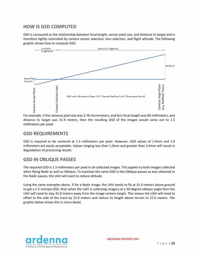
HOW IS GSD COMPUTED GSD is computed as the relationship between focal length, sensor pixel size, and distance to target and is therefore tightly controlled by camera sensor selection, lens selection, and flight altitude. The following graphic shows how to compute GSD.
For example, if the cameras pixel size was 3.76 micrometers, and lens focal length was 80 millimeters, and distance to target was 31.9 meters, then the resulting GSD of the images would come out to 1.5 millimeters per pixel.
GSD REQUIREMENTS GSD is required to be centered at 1.5 millimeters per pixel. However, GSD values of 1.4mm and 1.6 millimeters are easily acceptable. Values ranging less than 1.0mm and greater than 2.0mm will result in degradation of processing results.
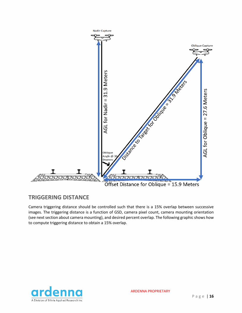
GSD IN OBLIQUE PASSES The required GSD is 1.5 millimeters per pixel in all collected images. This applies to both images collected when flying Nadir as well as Oblique. To maintain the same GSD in the Oblique passes as was obtained in the Nadir passes, the UAV will need to reduce altitude. Using the same examples above. If for a Nadir image, the UAV needs to fly at 31.9 meters above ground to get a 1.5 mm/pix GSD, then when the UAV is collecting imagery at a 30-degree oblique angle then the UAV will need to stay 31.9 meters away from the image centers target. This means the UAV will need to offset to the side of the track by 15.9 meters and reduce its height above terrain to 27.6 meters. The graphic below shows this in more detail.
ARDENNA PROPRIETARY P a g e | 16
TRIGGERING DISTANCE Camera triggering distance should be controlled such that there is a 15% overlap between successive images. The triggering distance is a function of GSD, camera pixel count, camera mounting orientation (see next section about camera mounting), and desired percent overlap. The following graphic shows how to compute triggering distance to obtain a 15% overlap.
ARDENNA PROPRIETARY P a g e | 17
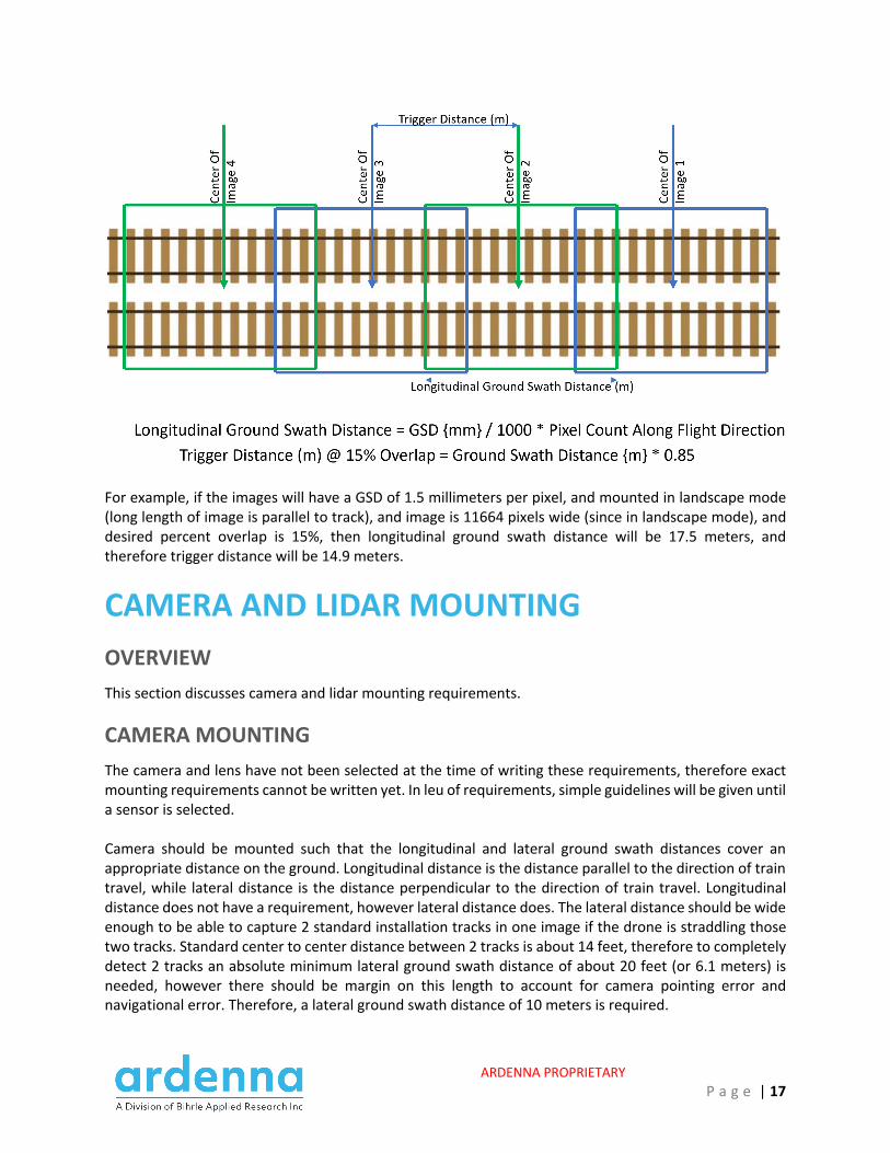
For example, if the images will have a GSD of 1.5 millimeters per pixel, and mounted in landscape mode (long length of image is parallel to track), and image is 11664 pixels wide (since in landscape mode), and desired percent overlap is 15%, then longitudinal ground swath distance will be 17.5 meters, and therefore trigger distance will be 14.9 meters.
CAMERA AND LIDAR MOUNTING OVERVIEW This section discusses camera and lidar mounting requirements.
CAMERA MOUNTING The camera and lens have not been selected at the time of writing these requirements, therefore exact mounting requirements cannot be written yet. In leu of requirements, simple guidelines will be given until a sensor is selected. Camera should be mounted such that the longitudinal and lateral ground swath distances cover an appropriate distance on the ground. Longitudinal distance is the distance parallel to the direction of train travel, while lateral distance is the distance perpendicular to the direction of train travel. Longitudinal distance does not have a requirement, however lateral distance does. The lateral distance should be wide enough to be able to capture 2 standard installation tracks in one image if the drone is straddling those two tracks. Standard center to center distance between 2 tracks is about 14 feet, therefore to completely detect 2 tracks an absolute minimum lateral ground swath distance of about 20 feet (or 6.1 meters) is needed, however there should be margin on this length to account for camera pointing error and navigational error. Therefore, a lateral ground swath distance of 10 meters is required.
ARDENNA PROPRIETARY P a g e | 18
Once a camera is selected a mounting orientation can then be determined. Let’s take for example a camera flown in a way to give a GSD of 1.5 mm/pixel and a width and height of 11664 and 8750 pixels respectively. The ground swath distances for this camera are then 17.5 and 13.1 meters respectively. This means that this camera can be mounted in landscape mode or portrait mode and still be able to capture 2 tracks in one image. As another example, lets take a camera that is 8000 pixels wide and 6000 pixels in height and also will have 1.5 mm/pixel GSD. In this case the ground swath distances for this camera are going to be 12 meters and 9 meters respectively. In this case the camera can only be mounted such that the long leg of the image is running perpendicular to the direction of the rails.
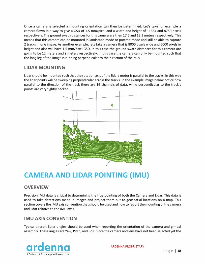
LIDAR MOUNTING Lidar should be mounted such that the rotation axis of the lidars motor is parallel to the tracks. In this way the lidar points will be sweeping perpendicular across the tracks. In the example image below notice how parallel to the direction of the track there are 16 channels of data, while perpendicular to the track’s points are very tightly packed.
CAMERA AND LIDAR POINTING (IMU) OVERVIEW Precision IMU data is critical to determining the true pointing of both the Camera and Lidar. This data is used to take detections made in images and project them out to geospatial locations on a map. This section covers the IMU axis convention that should be used and how to report the mounting of the camera and lidar relative to the IMU axes.
IMU AXIS CONVENTION Typical aircraft Euler angles should be used when reporting the orientation of the camera and gimbal assembly. These angles are Yaw, Pitch, and Roll. Since the camera and lens have not been selected yet the
ARDENNA PROPRIETARY P a g e | 19
axis convention, and associated MetaData fields, have been designed to allow for later reconfiguration of the camera mounting (see next sections about camera and lidar mounting orientation). In a typical aircraft the x, y, and z axis are chosen such that:
- The x axis points out the front nose of the aircraft - The y axis points out through the right wing of the aircraft - The z axis points out through the bottom of the aircrafts belly
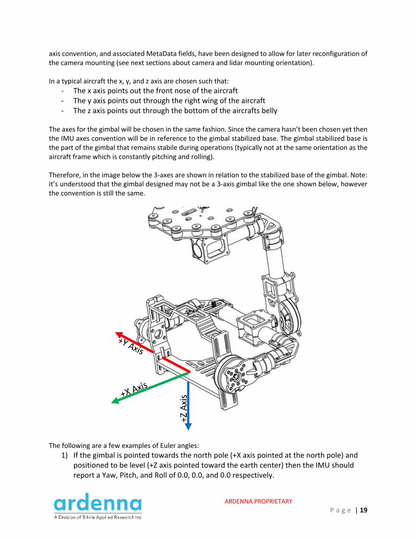
The axes for the gimbal will be chosen in the same fashion. Since the camera hasn’t been chosen yet then the IMU axes convention will be in reference to the gimbal stabilized base. The gimbal stabilized base is the part of the gimbal that remains stabile during operations (typically not at the same orientation as the aircraft frame which is constantly pitching and rolling). Therefore, in the image below the 3-axes are shown in relation to the stabilized base of the gimbal. Note: it’s understood that the gimbal designed may not be a 3-axis gimbal like the one shown below, however the convention is still the same.
The following are a few examples of Euler angles:
1) If the gimbal is pointed towards the north pole (+X axis pointed at the north pole) and positioned to be level (+Z axis pointed toward the earth center) then the IMU should report a Yaw, Pitch, and Roll of 0.0, 0.0, and 0.0 respectively.
ARDENNA PROPRIETARY P a g e | 20
2) If the gimbal is pointed towards the north pole and pitched down such that the camera is looking at the ground (-Z axis is pointed to the north pole and +X axis pointed toward the earth center), then the IMU should report a Yaw, Pitch, and Roll of 0.0, -90.0, and 0.0 respectively
3) If the gimbal is pointed east and pitched down such that the camera is looking at the ground (-Y axis is pointed at the north pole and +X axis is pointed towards the earth center), then the IMU should report a Yaw, Pitch and Roll of 90.0, -90.0 and 0.0 respectively
Care must be taken when reporting Euler angles when the gimbal is pointed straight down at the ground (which will be typical operations). In this scenario the payload will be in a common configuration called “Gimbal Lock” which is a situation where Yaw and Roll cannot easily be determined. There is math out there that allows for these angles to be determined and hopefully the chosen IMU outputs these values easily and no additional work needs to be done. However, I’ve seen some IMUs that do not report stable Euler angles in this configuration, if that is the case with the selected IMU then we may have to switch over to reporting quaternions in place of Euler angles.
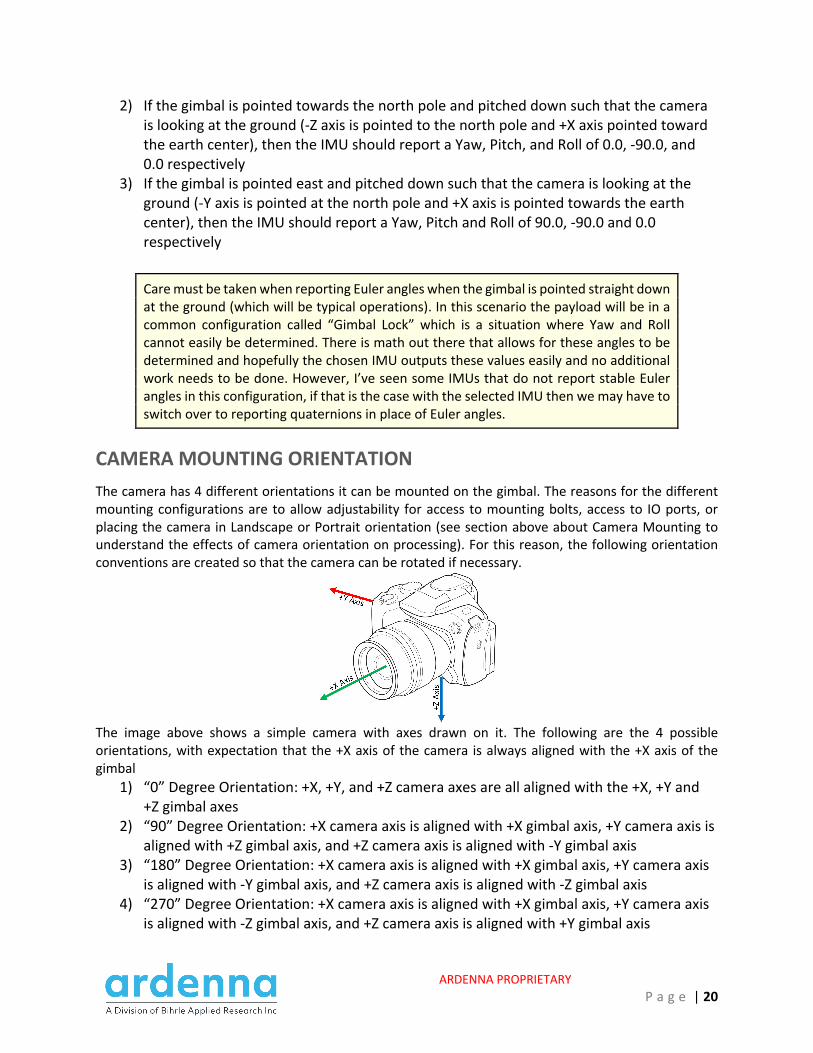
CAMERA MOUNTING ORIENTATION The camera has 4 different orientations it can be mounted on the gimbal. The reasons for the different mounting configurations are to allow adjustability for access to mounting bolts, access to IO ports, or placing the camera in Landscape or Portrait orientation (see section above about Camera Mounting to understand the effects of camera orientation on processing). For this reason, the following orientation conventions are created so that the camera can be rotated if necessary.
The image above shows a simple camera with axes drawn on it. The following are the 4 possible orientations, with expectation that the +X axis of the camera is always aligned with the +X axis of the gimbal
1) “0” Degree Orientation: +X, +Y, and +Z camera axes are all aligned with the +X, +Y and +Z gimbal axes
2) “90” Degree Orientation: +X camera axis is aligned with +X gimbal axis, +Y camera axis is aligned with +Z gimbal axis, and +Z camera axis is aligned with -Y gimbal axis
3) “180” Degree Orientation: +X camera axis is aligned with +X gimbal axis, +Y camera axis is aligned with -Y gimbal axis, and +Z camera axis is aligned with -Z gimbal axis
4) “270” Degree Orientation: +X camera axis is aligned with +X gimbal axis, +Y camera axis is aligned with -Z gimbal axis, and +Z camera axis is aligned with +Y gimbal axis

ARDENNA PROPRIETARY P a g e | 21
The above 4 mounting orientations should be used to determine what the correct “CameraMountOrientation” should be reported as in the image EXIF/XMP headers as well as the CSV MetaData file.
LIDAR MOUNTING ORIENTATION Like the camera, the Lidar also has 4 different orientations it can be mounted. The reasons for the different mounting are for space and mounting constraints as well as ensuring lidar is scanning correctly in relation to the direction of the tracks (see section above about Lidar Mounting to understand the effects of the lidar orientation on processing). For this reason, the following orientation conventions are created so the Lidar can be rotated if necessary.
The image above shows an Ouster OS1 lidar with X, Y, and Z axes drawn on it. The +X axis is chosen so it is opposite from the power/data plug. It is expected that the +X axis of the lidar is always aligned with the +X axis of the gimbal.
1) “0” Degree Orientation: +X, +Y, and +Z lidar axes are all aligned with the +X, +Y, and +Z gimbal axes
2) “90” Degree Orientation: +X lidar axis is aligned with +X gimbal axis, +Y lidar axis is aligned with +Z gimbal axis, and +Z lidar axis is aligned with -Y gimbal axis
3) “180” Degree Orientation: +X lidar axis is aligned with +X gimbal axis, +Y lidar axis is aligned with -Y gimbal axis, and +Z lidar axis is aligned with -Z gimbal axis
4) “270” Degree Orientation: +X lidar axis is aligned with +X gimbal axis, +Y lidar axis is aligned with -Z gimbal axis, and +Z lidar axis is aligned with +Y gimbal axis
The above 4 mounting orientations should be used to determine what the correct “LidarMountOrientation” should be reported as in the image EXIF/XMP headers as well as the CSV MetaData file.
CAMERA CALIBRATION Requirements to be added in next release
Related Documents