2022-07-13 | 0061342 Aqua TROLL 100/200 Operator’s manual Information subject to change without notice. In-Situ, In-Situ logo, Baro Merge, BaroTROLL, HERMIT, HydroVu™, iSitu, Pocket-Situ, RDO, RuggedCable, RuggedReader, SmarTROLL™, TROLL, VuSitu, and Win-Situ are trademarks or registered trademarks of In-Situ Inc.©2016. All rights reserved. This product may be covered by patents identified at www.in-situ.com/ patents

Welcome message from author
This document is posted to help you gain knowledge. Please leave a comment to let me know what you think about it! Share it to your friends and learn new things together.
Transcript
2022-07-13 | 0061342
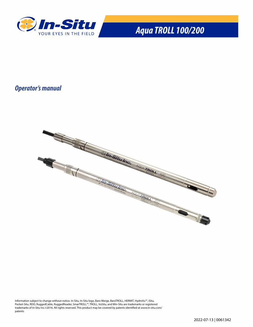
Aqua TROLL 100/200
Operator’s manual
Information subject to change without notice. In-Situ, In-Situ logo, Baro Merge, BaroTROLL, HERMIT, HydroVu™, iSitu, Pocket-Situ, RDO, RuggedCable, RuggedReader, SmarTROLL™, TROLL, VuSitu, and Win-Situ are trademarks or registered trademarks of In-Situ Inc.©2016. All rights reserved. This product may be covered by patents identified at www.in-situ.com/patents
2
Contents
Introduction ���������������������������������������������������������������������������������������������������������������������������������������������������� 5
System description ������������������������������������������������������������������������������������������������������������������������������������������������������������������������ 5
How to use this manual ��������������������������������������������������������������������������������������������������������������������������������������������������������������� 5
Conventions ������������������������������������������������������������������������������������������������������������������������������������������������������������������������������������� 5
Certification �������������������������������������������������������������������������������������������������������������������������������������������������������������������������������������� 5
Unpacking and inspection ��������������������������������������������������������������������������������������������������������������������������������������������������������� 6
To our customers ���������������������������������������������������������������������������������������������������������������������������������������������������������������������������� 6
How to contact us �������������������������������������������������������������������������������������������������������������������������������������������������������������������������� 6
System Components��������������������������������������������������������������������������������������������������������������������������������������� 9
Instrument ���������������������������������������������������������������������������������������������������������������������������������������������������������������������������������������� 9
Cable ��������������������������������������������������������������������������������������������������������������������������������������������������������������������������������������������������� 9
Power components ���������������������������������������������������������������������������������������������������������������������������������������������������������������������12
Installation accessories ��������������������������������������������������������������������������������������������������������������������������������������������������������������13
Product Specifications ��������������������������������������������������������������������������������������������������������������������������������� 14
Product Specifications — Conductivity Sensor ����������������������������������������������������������������������������������������������������������������15
Product Specifications — Pressure (Aqua Troll 200 Instrument) ��������������������������������������������������������������������������������15
Product Specifications — Temperature �������������������������������������������������������������������������������������������������������������������������������16
Control Software ������������������������������������������������������������������������������������������������������������������������������������������ 17
VuSitu �����������������������������������������������������������������������������������������������������������������������������������������������������������������������������������������������17
Win-Situ 5 ����������������������������������������������������������������������������������������������������������������������������������������������������������������������������������������17
Getting Started ��������������������������������������������������������������������������������������������������������������������������������������������� 18
Select a TROLL Com for Communication ����������������������������������������������������������������������������������������������������������������������������18
Connect the Hardware ���������������������������������������������������������������������������������������������������������������������������������������������������������������18
USB Troll Com ��������������������������������������������������������������������������������������������������������������������������������������������������������������������������������18
Twist-Lock cable connections��������������������������������������������������������������������������������������������������������������������������������������������������19
Connecting a Cable to the Wireless TROLL Com���������������������������������������������������������������������������������������������������������������20
Connecting Your Instrument to VuSitu ������������������������������������������������������������������������������������������������������� 21
Connecting to VuSitu ������������������������������������������������������������������������������������������������������������������������������������������������������������������21
Vusitu Menu Options ������������������������������������������������������������������������������������������������������������������������������������������������������������������21
Live Readings Screen ������������������������������������������������������������������������������������������������������������������������������������������������������������������22
Snapshot Mode �����������������������������������������������������������������������������������������������������������������������������������������������������������������������������22
Live Readings Mode ��������������������������������������������������������������������������������������������������������������������������������������������������������������������22
Changing Parameters and Units ���������������������������������������������������������������������������������������������������������������������������������������������23
Downloading and Sharing Your Data �����������������������������������������������������������������������������������������������������������������������������������23
Sharing Data ����������������������������������������������������������������������������������������������������������������������������������������������������������������������������������24
1-970-498-1500 www.in-situ.com
3
Viewing Data on a Mac or PC ���������������������������������������������������������������������������������������������������������������������������������������������������24
Using Win-Situ® 5 Software ������������������������������������������������������������������������������������������������������������������������� 25
Launch the Software and Connect Instrument �����������������������������������������������������������������������������������������������������������������25
Bluetooth & Wireless TROLL Com �������������������������������������������������������������������������������������������������������������������������������������������26
Check the Conductivity Calibration ��������������������������������������������������������������������������������������������������������������������������������������31
Prepare to Log Data���������������������������������������������������������������������������������������������������������������������������������������������������������������������31
Tips for Aqua TROLL data logs �������������������������������������������������������������������������������������������������������������������������������������������������32
Disconnect ��������������������������������������������������������������������������������������������������������������������������������������������������������������������������������������34
Conductivity�������������������������������������������������������������������������������������������������������������������������������������������������� 35
About Conductivity ���������������������������������������������������������������������������������������������������������������������������������������������������������������������35
How is conductivity measured ������������������������������������������������������������������������������������������������������������������������������������������������35
Calibration ��������������������������������������������������������������������������������������������������������������������������������������������������������������������������������������35
Available parameters ������������������������������������������������������������������������������������������������������������������������������������������������������������������39
Shallow deployment �������������������������������������������������������������������������������������������������������������������������������������������������������������������40
Maintenance and Recalibration ����������������������������������������������������������������������������������������������������������������������������������������������40
Pressure and Level ���������������������������������������������������������������������������������������������������������������������������������������� 41
About the Pressure Sensor �������������������������������������������������������������������������������������������������������������������������������������������������������41
Non-vented (absolute) vs� vented (gauged) sensors ������������������������������������������������������������������������������������������������������41
Pressure, Depth and Level���������������������������������������������������������������������������������������������������������������������������������������������������������41
Configuring Depth and Level ��������������������������������������������������������������������������������������������������������������������������������������������������42
Pressure sensor calibration �������������������������������������������������������������������������������������������������������������������������������������������������������44
Barometric compensation of non-vented pressure & level data ��������������������������������������������������������������������������������45
Field Installation ������������������������������������������������������������������������������������������������������������������������������������������� 47
Stabilization Time �������������������������������������������������������������������������������������������������������������������������������������������������������������������������50
Shallow Deployment ������������������������������������������������������������������������������������������������������������������������������������������������������������������50
Installation of a Non-Vented Aqua Troll �������������������������������������������������������������������������������������������������������������������������������50
Analog, SDI-12 and Modbus Connections �������������������������������������������������������������������������������������������������� 51
Care and Maintenance ��������������������������������������������������������������������������������������������������������������������������������� 58
Operating Considerations ���������������������������������������������������������������������������������������������������������������������������������������������������������58
Storage ���������������������������������������������������������������������������������������������������������������������������������������������������������������������������������������������58
General Maintenance �����������������������������������������������������������������������������������������������������������������������������������������������������������������58
Batteries �������������������������������������������������������������������������������������������������������������������������������������������������������������������������������������������59
Cleaning ������������������������������������������������������������������������������������������������������������������������������������������������������������������������������������������59
Conductivity Sensor ��������������������������������������������������������������������������������������������������������������������������������������������������������������������60
Troubleshooting ������������������������������������������������������������������������������������������������������������������������������������������� 61
Troubleshooting Connections�������������������������������������������������������������������������������������������������������������������������������������������������61
Troubleshooting Data Logs ������������������������������������������������������������������������������������������������������������������������������������������������������61
Troubleshooting Parameter Configuration ������������������������������������������������������������������������������������������������������������������������62
1-970-498-1500 www.in-situ.com

4
Troubleshooting Conductivity Calibration �������������������������������������������������������������������������������������������������������������������������62
Declaration of Conformity - Aqua TROLL 200 �������������������������������������������������������������������������������������������� 64
Declaration of Conformity - TROLL Com ����������������������������������������������������������������������������������������������������� 65
1-970-498-1500 www.in-situ.com
IntroductionThis manual is intended to describe the characteristics, operation, calibration, and maintenance of the AquaTROLL 100 and AquaTROLL 200 Sondes�
The Aqua TROLL® Instrument is a compact, modular system for measuring conductivity and temperature in natural groundwater and surface water, as well as industrial, wastewater, and other installations� Aqua TROLL 200 Instruments have the added capability of measuring level� Components include the instrument, vented and non-vented cables, communication cables, external power accessories, desiccants, and other installation accessories, calibration solutions, and software�
This Operator’s Manual is designed as a start-up guide and a permanent reference for Aqua TROLL 100 and 200 Instruments�
Throughout this operator’s manual you will see the following symbols�
The Aqua TROLL Instrument complies with all applicable directives required by CE and the FCC and found to comply with EN 61326, ICES-003, and FCC Part 15 specifications� Declarations of conformity may be found at end of this manual�
• Section 1: Introduction to the Aqua TROLL Operator’s Manual and to In-Situ Inc� — Warranty provisions —Instrument repair & return recommendations
• Section 2: System Components — Accessories — Product specifications
• Section 3: Getting Started — Attaching cable — Installing and opening the software
• Section 4: Using Win-Situ — Connecting for the first time — Customizing the Home screen — Setting the clock —Setting a device site — Calibrating conductivity — Preparing to log data — Disconnecting
• Section 5: The Conductivity Sensor: Description — Calibration — Available parameters
• Section 6: The Pressure (Level) Sensor: The two basic types of pressure sensors — Factory and field calibration
• Section 7: Field Installation — Guidelines and precautions for long-term deployment of the Aqua TROLL Instrument
• Section 8: Connecting for Use with SDI-12, Analog (4-20 mA), and Modbus Loggers and Controllers
• Section 9: Care and Maintenance
• Section 10: Troubleshooting
System description
How to use this manual
Conventions
Certification
51-970-498-1500 www.in-situ.com
Unpacking and inspection
To our customers
Your Aqua TROLL Instrument was carefully inspected before shipping� Check for any physical damage sustained during shipment� Notify In-Situ and file a claim with the carriers involved if there is any such damage; do not attempt to operate the instrument� Accessories may be shipped separately and should also be inspected for physical damage and the fulfillment of your order�
The serial number is engraved on the body of the instrument� It is also programmed into the instrument and displayed when the instrument is connected to a computer running Win-Situ® 5 or to a mobile device with VuSitu software� We recommend that owners keep a separate record of this number�
In-Situ® Inc�, (In-Situ) warrants that all new Aqua TROLL® 100 and 200 Instruments shall be free from defects in materials and workmanship for a period of two years when properly installed and operated in accordance with the instruction manuals provided by, or available through, In-Situ Inc�, and when used within the design specifications for the product� Products and accessory products including batteries, which are manufactured by others, carry the warranty of that manufacturer, or 30 days, whichever is greater� The warranty period for all products begins on the day the product is shipped to the customer or distributor� The complete Warranty Policy is available on the In-Situ website�
Thank you for your purchase of an In-Situ product� We are glad you chose us and our products to help you with your environmental monitoring needs� In-Situ Inc� has been designing and manufacturing world-class environmental monitoring instrumentation for over 25 years in the Rocky Mountains of the United States� As it was in the beginning, our expectation is that this product will provide you with many troublefree years of use� To that end, we pride ourselves on delivering the best customer service and support possible—24 hours a day, 7 days a week� We believe that this level of commitment to you, our customer, is imperative in helping you ensure clean, safe groundwater and surface water resources around the globe� We also understand the need for accurate, reliable assessments and we continue to make significant investments in Research and Development to ensure that we deliver the latest technological innovations to support your needs�
Whether you are gathering information about a body of water for a few moments, or over a period of years, you can rely upon us to provide you with a quality product and outstanding customer support at a fair price and have that product delivered to you when and where you need it�We want your experience with In-Situ Inc� to be pleasant and professional, whether you are renting or purchasing from us� We would be pleased to hear from you and to learn more about your needs and your experiences with our products� Again, we thank you for choosing In-Situ Inc� and we look forward to serving your needs now, and in the future�
Serial Number
Warranty Provisions
How to contact usTechnical support 1-800-446-7488, option 3
Toll-free 24 hours a day in the U.S.A. and Canada
Address:In-Situ, Inc�221 E� Lincoln AveFort Collins, CO 80524 U�S�A�
Phone: 970-498-1500970-498-1598
Email: support @in-situ�com
61-970-498-1500 www.in-situ.com
To Obtain Repair Service
Guidelines for Cleaning Returned Equipment
If you suspect that your instrument is malfunctioning and repair is required, you can help ensure efficient servicing by following these guidelines:
1 Call or e-mail In-Situ Technical Support (support@in-situ�com)� Have the equipment with you when you call�
2 Be prepared to describe the problem, including how the instrument was used and the conditions noted at the time of the malfunction�
3 If Tech Support determines that service is needed, they will ask that you download and complete a Return Materials Authorization Form available on the In-Situ website under Contact/Returns for Service�
4 Clean the instrument and cable� Decontaminate thoroughly if it has been used in a toxic or hazardous environment� See “Guidelines for Cleaning Returned Equipment” on page 6
5 Remove all sensors and accessories that are not required for the repair prior to returning unit�
6 Mark the RMA number clearly on the side of the box with a marker or label� Please keep your RMA number for future reference� Return unit for repair to the following address:
In-Situ, Inc� Attn: RMA #XXXXX221 E� Lincoln AveFort Collins, CO 80524 U�S�A�
To reduce waste, please use your original shipping container, if it is in good condition� The warranty does not cover damage during transit� We recommend the customer insure all shipments� Warranty repairs will be shipped back prepaid�
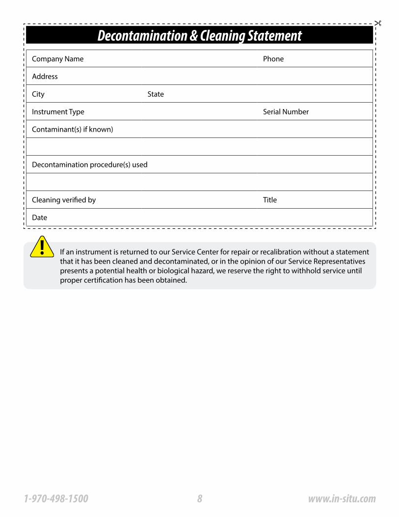
Please help us protect the health and safety of our employees by cleaning and decontaminating equipment that has been subjected to any potential biological or health hazards, and labeling such equipment� Unfortunately, we cannot service your equipment without such notification� Please complete and sign the form on page 7 (or a similar statement certifying that the equipment has been cleaned and decontaminated) and send it along to us with each downhole instrument�
• We recommend a cleaning solution, such as Alconox®, a glassware cleaning product available from In-Situ (Catalog No� 0029810) and laboratory supply houses�
• DO NOT remove the nose cone� DO NOT use any object to clean the sensor face�
• Clean the pressure sensor by soaking only in cleaning solution or clean water�
• Clean all cabling� Remove all foreign matter�
• Clean cable connector(s) with a clean, dry cloth� Do not submerge�
• Clean the probe body—including the nose
71-970-498-1500 www.in-situ.com
Decontamination & Cleaning StatementCompany Name Phone
Address
City State
Instrument Type Serial Number
Contaminant(s) if known)
Decontamination procedure(s) used
Cleaning verified by Title
Date
If an instrument is returned to our Service Center for repair or recalibration without a statement that it has been cleaned and decontaminated, or in the opinion of our Service Representatives presents a potential health or biological hazard, we reserve the right to withhold service until proper certification has been obtained�
81-970-498-1500 www.in-situ.com
System ComponentsInstrument
Cable
The completely sealed Aqua TROLL Instrument contains conductivity and temperature sensors, real-time clock, microprocessor, sealed lithium battery, data logger, and memory� Aqua TROLL 200 Instruments include a vented or non-vented pressure sensor in a variety of ranges�
Several basic cable types are used in the Aqua TROLL system�
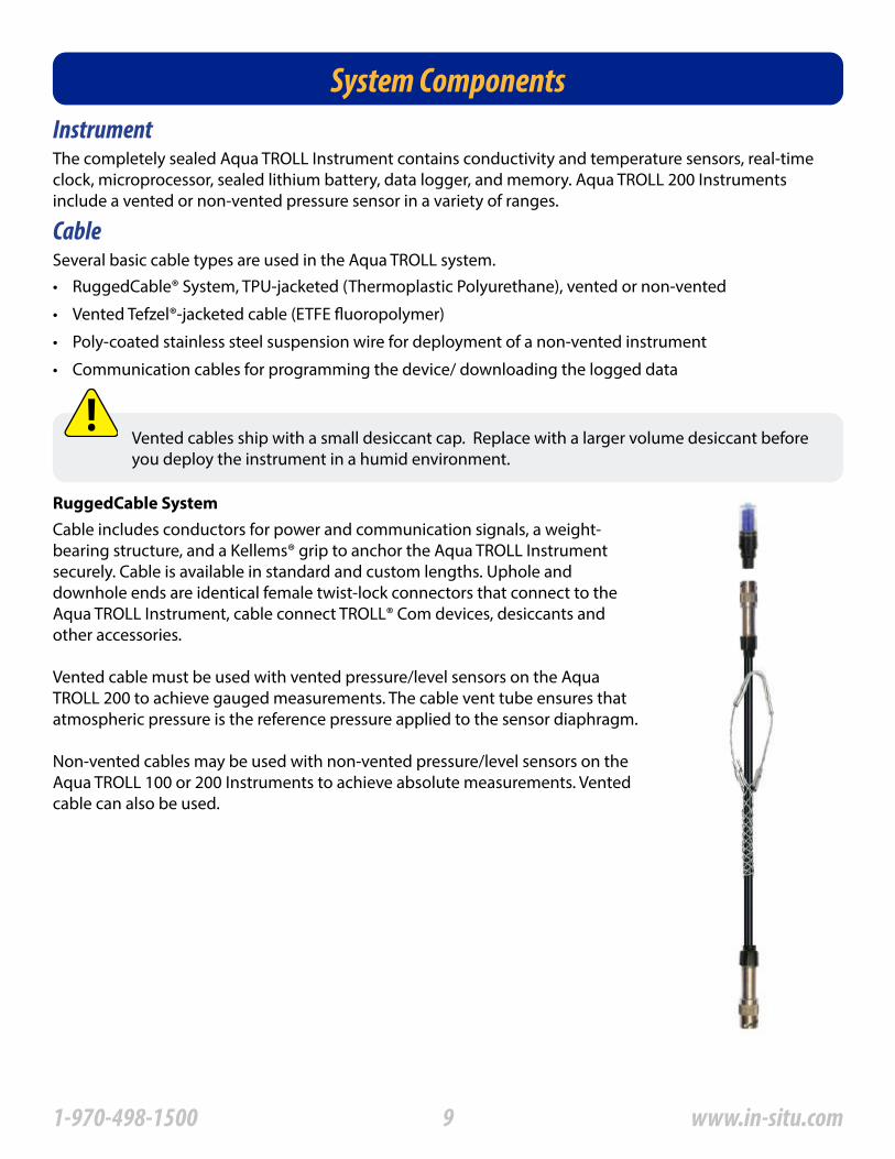
RuggedCable System
• RuggedCable® System, TPU-jacketed (Thermoplastic Polyurethane), vented or non-vented
• Vented Tefzel®-jacketed cable (ETFE fluoropolymer)
• Poly-coated stainless steel suspension wire for deployment of a non-vented instrument
• Communication cables for programming the device/ downloading the logged data
Cable includes conductors for power and communication signals, a weight-bearing structure, and a Kellems® grip to anchor the Aqua TROLL Instrument securely� Cable is available in standard and custom lengths� Uphole and downhole ends are identical female twist-lock connectors that connect to the Aqua TROLL Instrument, cable connect TROLL® Com devices, desiccants and other accessories�
Vented cable must be used with vented pressure/level sensors on the Aqua TROLL 200 to achieve gauged measurements� The cable vent tube ensures that atmospheric pressure is the reference pressure applied to the sensor diaphragm�
Non-vented cables may be used with non-vented pressure/level sensors on the Aqua TROLL 100 or 200 Instruments to achieve absolute measurements� Vented cable can also be used�
Vented cables ship with a small desiccant cap� Replace with a larger volume desiccant before you deploy the instrument in a humid environment�
91-970-498-1500 www.in-situ.com
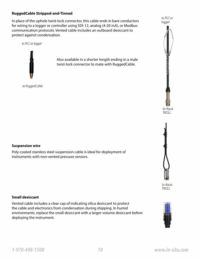
RuggedCable Stripped-and-Tinned
Suspension wire
Small desiccant
In place of the uphole twist-lock connector, this cable ends in bare conductors for wiring to a logger or controller using SDI-12, analog (4-20 mA), or Modbus communication protocols� Vented cable includes an outboard desiccant to protect against condensation�
Poly-coated stainless steel suspension cable is ideal for deployment of instruments with non-vented pressure sensors�
Vented cable includes a clear cap of indicating silica desiccant to protect the cable and electronics from condensation during shipping� In humid environments, replace the small desiccant with a larger-volume desiccant before deploying the instrument�
Also available in a shorter length ending in a male twist-lock connector to mate with RuggedCable�
101-970-498-1500 www.in-situ.com
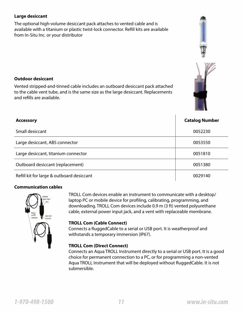
Large desiccant
Outdoor desiccant
Communication cables
The optional high-volume desiccant pack attaches to vented cable and is available with a titanium or plastic twist-lock connector� Refill kits are available from In-Situ Inc� or your distributor
Vented stripped-and-tinned cable includes an outboard desiccant pack attached to the cable vent tube, and is the same size as the large desiccant� Replacements and refills are available�
Accessory Catalog Number
Small desiccant 0052230
Large desiccant, ABS connector 0053550
Large desiccant, titanium connector 0051810
Outboard desiccant (replacement) 0051380
Refill kit for large & outboard desiccant 0029140
TROLL Com devices enable an instrument to communicate with a desktop/laptop PC or mobile device for profiling, calibrating, programming, and downloading� TROLL Com devices include 0�9 m (3 ft) vented polyurethane cable, external power input jack, and a vent with replaceable membrane�
TROLL Com (Cable Connect)Connects a RuggedCable to a serial or USB port� It is weatherproof and withstands a temporary immersion (IP67)�
TROLL Com (Direct Connect)Connects an Aqua TROLL Instrument directly to a serial or USB port� It is a good choice for permanent connection to a PC, or for programming a non-vented Aqua TROLL Instrument that will be deployed without RuggedCable� It is not submersible�
111-970-498-1500 www.in-situ.com
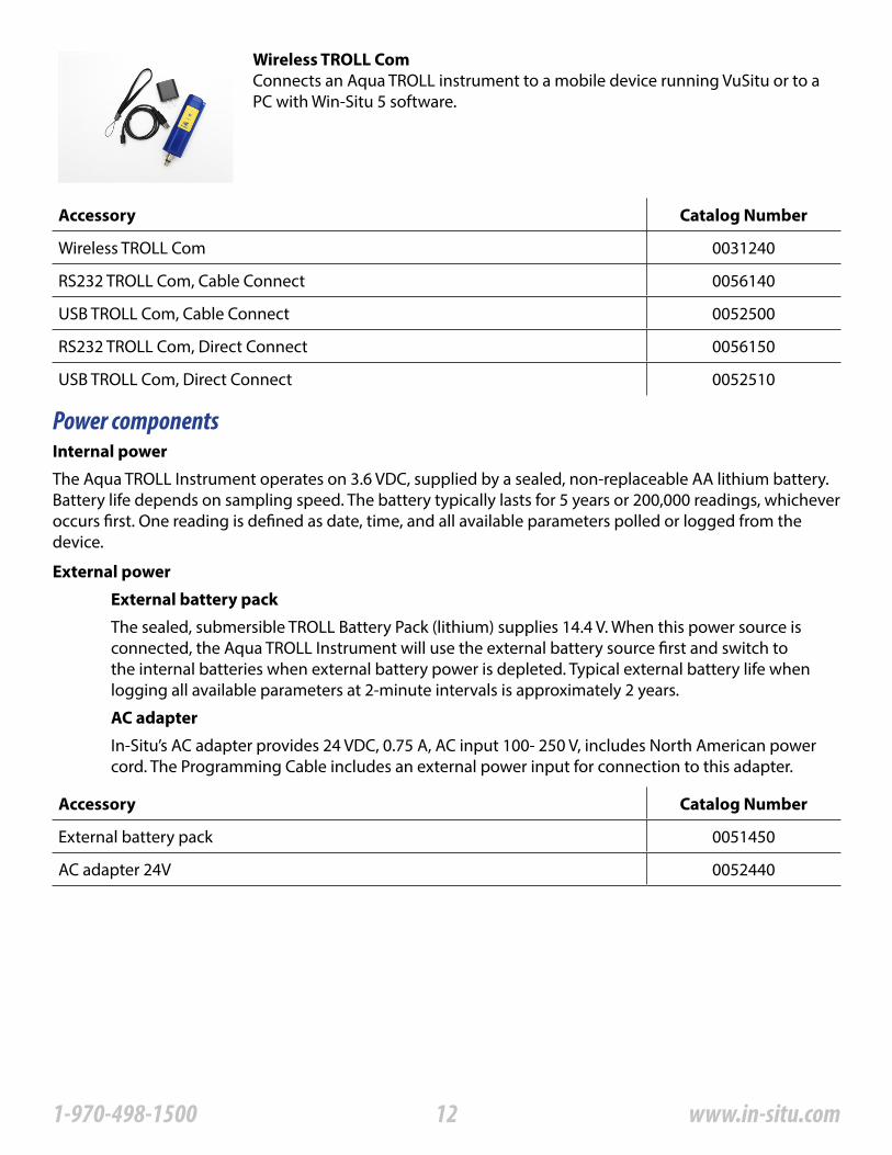
Wireless TROLL ComConnects an Aqua TROLL instrument to a mobile device running VuSitu or to a PC with Win-Situ 5 software�
Accessory Catalog Number
Wireless TROLL Com 0031240
RS232 TROLL Com, Cable Connect 0056140
USB TROLL Com, Cable Connect 0052500
RS232 TROLL Com, Direct Connect 0056150
USB TROLL Com, Direct Connect 0052510
Accessory Catalog Number
External battery pack 0051450
AC adapter 24V 0052440
Power componentsInternal power
External power
External battery pack
AC adapter
The Aqua TROLL Instrument operates on 3�6 VDC, supplied by a sealed, non-replaceable AA lithium battery� Battery life depends on sampling speed� The battery typically lasts for 5 years or 200,000 readings, whichever occurs first� One reading is defined as date, time, and all available parameters polled or logged from the device�
The sealed, submersible TROLL Battery Pack (lithium) supplies 14�4 V� When this power source is connected, the Aqua TROLL Instrument will use the external battery source first and switch to the internal batteries when external battery power is depleted� Typical external battery life when logging all available parameters at 2-minute intervals is approximately 2 years�
In-Situ’s AC adapter provides 24 VDC, 0�75 A, AC input 100- 250 V, includes North American power cord� The Programming Cable includes an external power input for connection to this adapter�
121-970-498-1500 www.in-situ.com
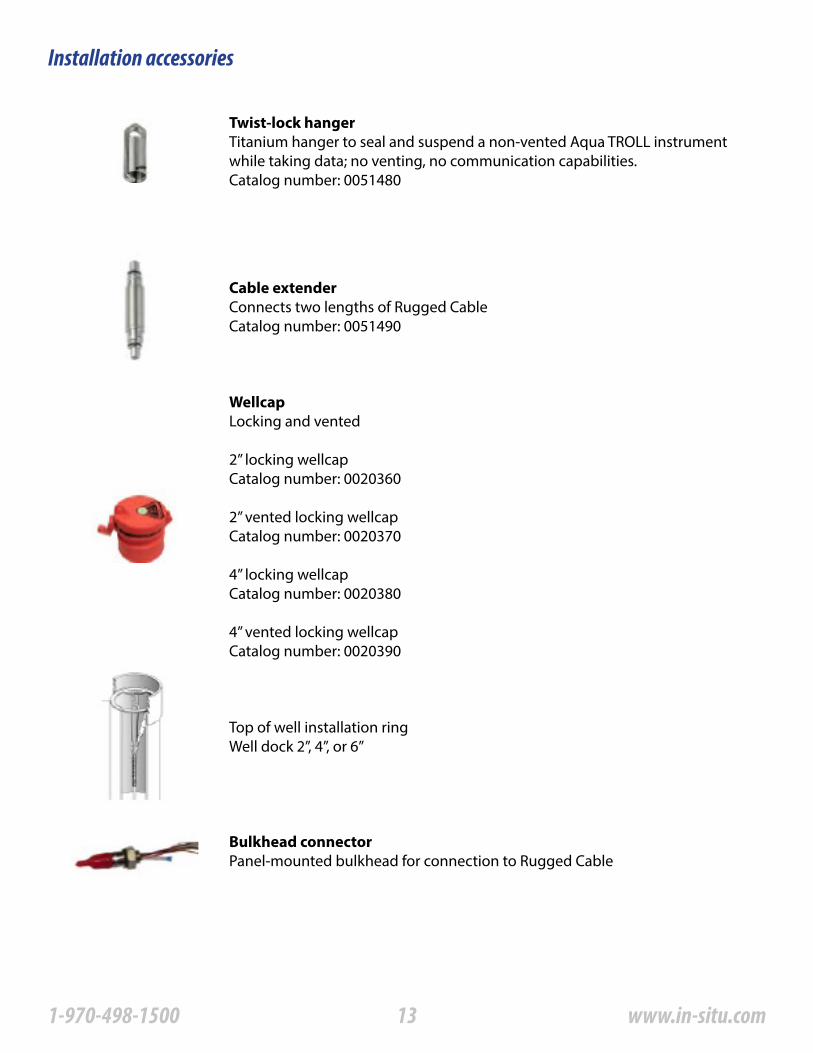
Installation accessories
Twist-lock hangerTitanium hanger to seal and suspend a non-vented Aqua TROLL instrument while taking data; no venting, no communication capabilities�Catalog number: 0051480
Cable extenderConnects two lengths of Rugged CableCatalog number: 0051490
WellcapLocking and vented
2” locking wellcapCatalog number: 0020360
2” vented locking wellcapCatalog number: 0020370
4” locking wellcapCatalog number: 0020380
4” vented locking wellcapCatalog number: 0020390
Top of well installation ringWell dock 2”, 4”, or 6”
Bulkhead connectorPanel-mounted bulkhead for connection to Rugged Cable
131-970-498-1500 www.in-situ.com
Product Specifications
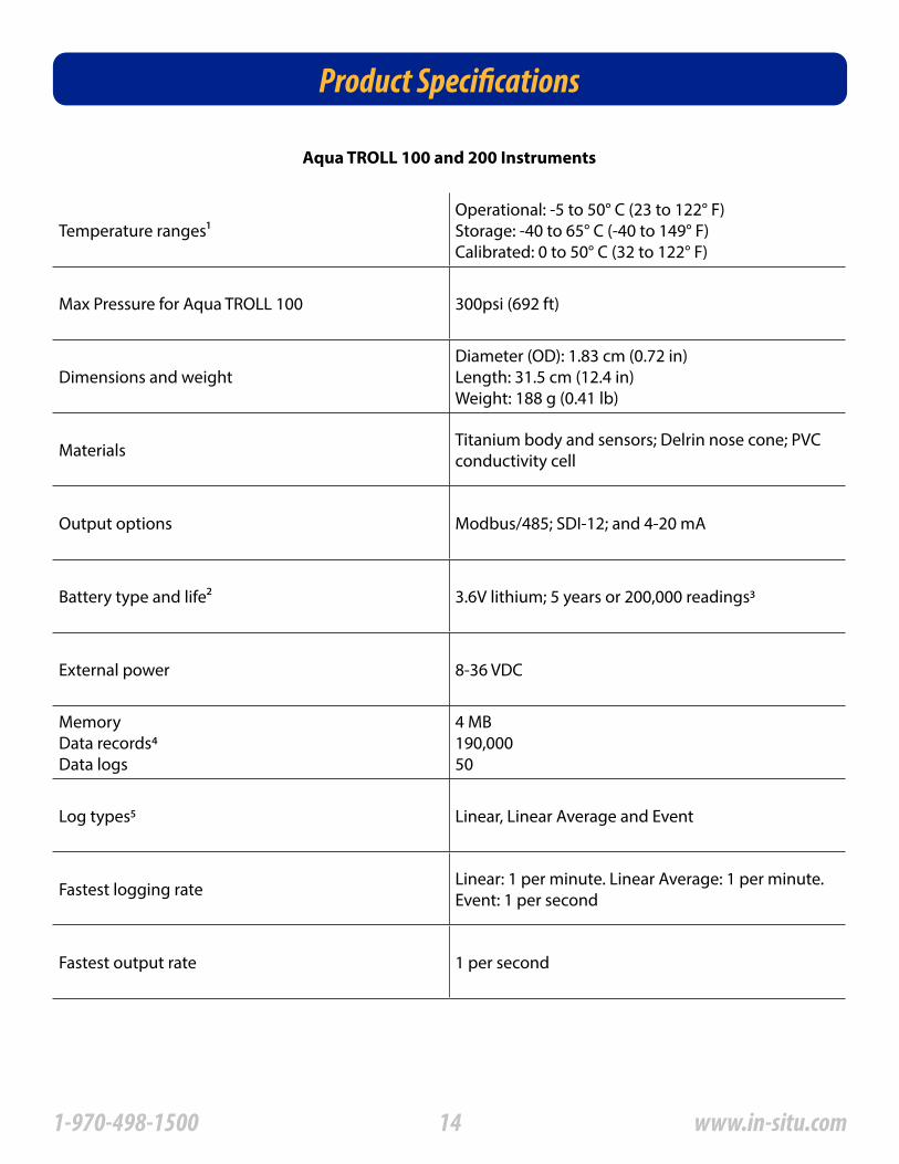
Aqua TROLL 100 and 200 Instruments
Temperature ranges1Operational: -5 to 50° C (23 to 122° F)Storage: -40 to 65° C (-40 to 149° F)Calibrated: 0 to 50° C (32 to 122° F)
Max Pressure for Aqua TROLL 100 300psi (692 ft)
Dimensions and weightDiameter (OD): 1�83 cm (0�72 in) Length: 31�5 cm (12�4 in) Weight: 188 g (0�41 lb)
Materials Titanium body and sensors; Delrin nose cone; PVC conductivity cell
Output options Modbus/485; SDI-12; and 4-20 mA
Battery type and life2 3�6V lithium; 5 years or 200,000 readings3
External power 8-36 VDC
MemoryData records4Data logs
4 MB190,00050
Log types5 Linear, Linear Average and Event
Fastest logging rate Linear: 1 per minute� Linear Average: 1 per minute� Event: 1 per second
Fastest output rate 1 per second
141-970-498-1500 www.in-situ.com

Product Specifications — Conductivity Sensor
Product Specifications — Pressure (Aqua Troll 200 Instrument)
Conductivity Sensor Type: Balanced 4-electrode cell
Methods EPA Method 120�1; Standard Methods 2510
Range, accuracy and resolution
Range: 0 to 100,000 µS/cmAccuracy: ±0�5% of reading + 1 µS/cm when reading less than 80,000 µS/cm ±1�0% of reading above 80,000 µS/cm Resolution: 0�1 µS/cm
Parameters supported6Actual conductivity Specific conductivity7Salinity8Total dissolved solids ResistivityDensity (water salinity)
Range:0 to 100,000 µS/cm0 to 100,000 µS/cm0 to 42 PSU0 to 82 ppt10 to 200,000 Ohms-cm 0�98 to 1�14 g/cm
Pressure/Level Sensor9Type: Piezoresistive; Pressure/level areavailable only to the Aqua TROLL 200Instrument
Range
Absolute (non-vented) 30 psia: 11 m (35�8 ft) 100 psia: 60 m (197 ft) 300 psia: 200 m (658�7 ft)
Gauged (vented)5 psig: 3�5 m (11�5 ft)15 psig: 11 m (35 ft)30 psig: 21 m (69 ft)100 psig: 70 m (231 ft)300 psig: 210 m (692 ft)
Burst pressure Maximum 2x range; burst 3x range
Accuracy (FS)10 ±0�05%11
Resolution: 0�005% FS or better
Long-term stability12 < 0�1% FS
Units of measurePressure: psi, kPa, bar, mbar, mmHg, inHg,cmH2O, inH2O)Level: in, ft, mm, cm, m
151-970-498-1500 www.in-situ.com

Product Specifications — Temperature
Temperature sensor13
Method EPA Method 170�1
Accuracy and resolution Accuracy: ±0�1° C or better
Units of measure Celsius of Fahrenheit
Product Specifications- Footnotes1Temperature range for non-freezing liquids2Typical battery life when used within the factory-calibrated temperature range31 reading = date/time plus all available parameters polled or logged from device41 data record = date/time plus 3 parameters logged (no wrapping) from device5External power or battery pack is recommended when using Linear Average or Event logging modes6Parameters derived from temperature at 25° C and actual conductivity range of 0 to 100,000 µS/cm with a ±0�5% + 1 µS/cm accuracy7Derived from Standard Methods 2510B8Defined by the Practical Salinity Scale 1978; Standard Methods 2520B9Real-time level compensation based on water density10Accuracy with 4-20mA output option: ±0�25% FS11Across factory-calibrated pressure and temperature ranges12Includes linearity and hysteresis over one year13Temperature response varies by temperature change and environmental conditions in typical field conditions� T95 > 5 min�
Specifications are subject to change without notice�Delrin is a registered trademark of E�l� duPont de Nemours and Company�NIST is a registered trademark of the National Institute of Standards and Technology�
161-970-498-1500 www.in-situ.com
Control Software
Win-Situ® 5 Software is easy-to-use software for programming Aqua TROLL Instruments on a desktop or laptop computer� Win-Situ provides instrument control for direct reads and profiling, calibration, long-term data logging, data downloads, data viewing, data export to popular spreadsheet programs, choice of units and other display options, and battery/memory usage tracking� Win-Situ® Plus enables configuration of networks and telemetry� Minimum system requirements: 400 MHz Pentium® II processor; 128 MB RAM, 100 MB free disk space; Internet Explorer® 6�01 or higher; Windows® 2000 Professional SP4 or higher, Windows XP Professional SP2 or higher, or Windows Vista SP1 or higher; Windows 7 or higher, CD-ROM drive; serial or USB port�
Accessory Catalog Number
Win-Situ 5 (no license required) 0051980
Win-Situ 5 Plus license 0053560
VuSitu
Win-Situ 5
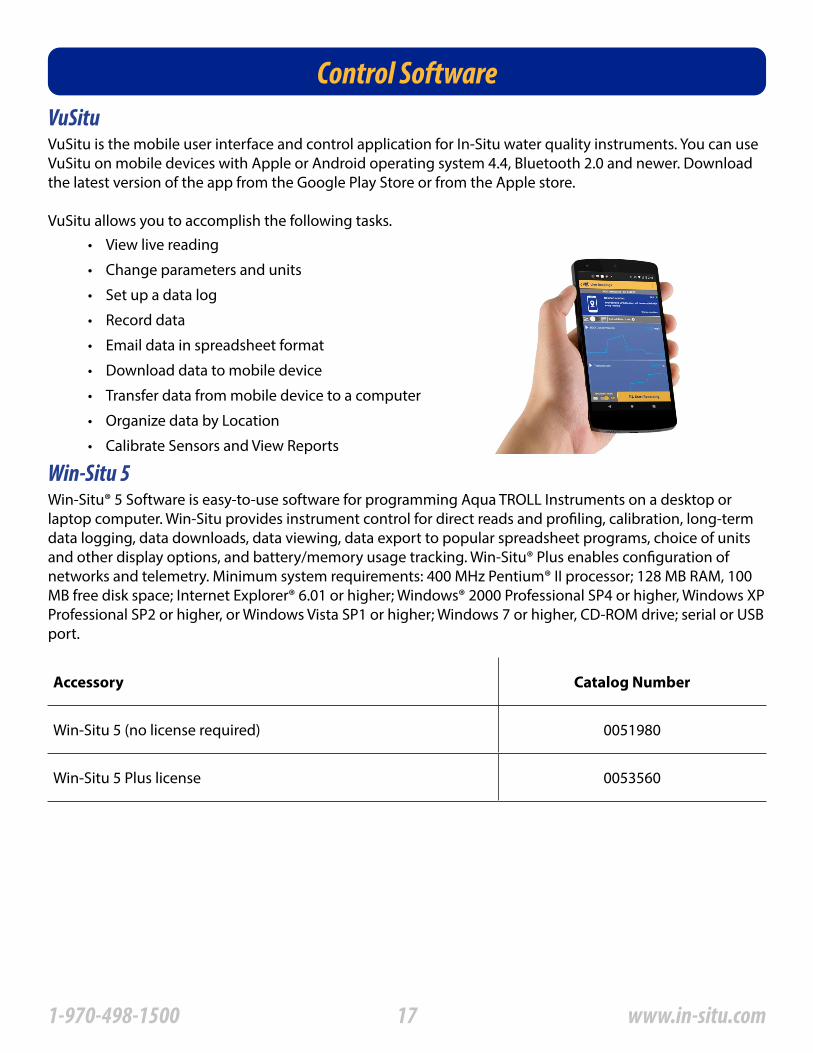
VuSitu is the mobile user interface and control application for In-Situ water quality instruments� You can use VuSitu on mobile devices with Apple or Android operating system 4�4, Bluetooth 2�0 and newer� Download the latest version of the app from the Google Play Store or from the Apple store�
VuSitu allows you to accomplish the following tasks�• View live reading
• Change parameters and units
• Set up a data log
• Record data
• Email data in spreadsheet format
• Download data to mobile device
• Transfer data from mobile device to a computer
• Organize data by Location
• Calibrate Sensors and View Reports
171-970-498-1500 www.in-situ.com
Getting StartedThis section provides a quick overview of the initial steps necessary to get the instrument ready to communicate:
The figure below shows the function and compatibility of the different models of cable and direct-connect TROLL Coms�
TIPS: A Direct Connect TROLL Com may be preferred for programming an Aqua TROLL Instrument that will be deployed on wire�
RuggedCable and a Cable Connect TROLL Com are required for communication with the device while deployed, but programming can be done with any TROLL Com connection�
• Select the appropriate TROLL Com for communication� This determines the hardware connections, and may influence the software installation� The drawing on the following page shows the function of the different TROLL Com models�
• Install the software�
• Connect the hardware, based on the selected TROLL Com�
• Open the software and establish communication with the Aqua TROLL Insturment� See “Using Win-Situ® 5 Software” on page 23 for an overview of Win-Situ operations�
Select a TROLL Com for Communication
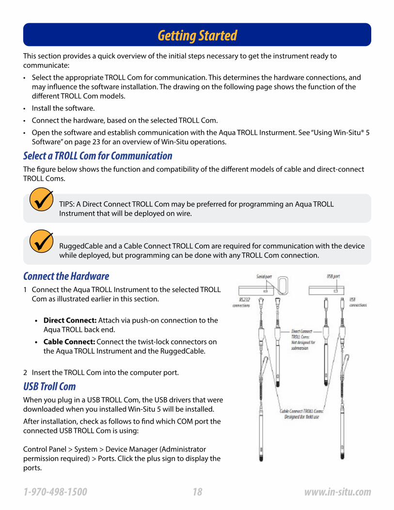
Connect the Hardware
USB Troll Com
1 Connect the Aqua TROLL Instrument to the selected TROLL Com as illustrated earlier in this section�
• Direct Connect: Attach via push-on connection to the Aqua TROLL back end�
• Cable Connect: Connect the twist-lock connectors on the Aqua TROLL Instrument and the RuggedCable�
2 Insert the TROLL Com into the computer port�
When you plug in a USB TROLL Com, the USB drivers that were downloaded when you installed Win-Situ 5 will be installed�
After installation, check as follows to find which COM port theconnected USB TROLL Com is using:
Control Panel > System > Device Manager (Administrator permission required) > Ports� Click the plus sign to display the ports�
181-970-498-1500 www.in-situ.com
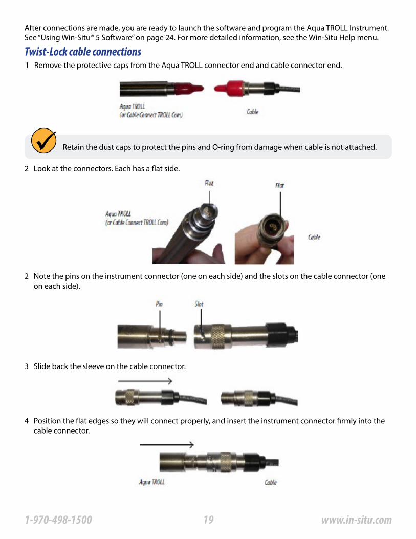
After connections are made, you are ready to launch the software and program the Aqua TROLL Instrument� See “Using Win-Situ® 5 Software” on page 24� For more detailed information, see the Win-Situ Help menu�
Twist-Lock cable connections1 Remove the protective caps from the Aqua TROLL connector end and cable connector end�
2 Look at the connectors� Each has a flat side�
2 Note the pins on the instrument connector (one on each side) and the slots on the cable connector (one on each side)�
4 Position the flat edges so they will connect properly, and insert the instrument connector firmly into the cable connector�
3 Slide back the sleeve on the cable connector�
Retain the dust caps to protect the pins and O-ring from damage when cable is not attached�
191-970-498-1500 www.in-situ.com
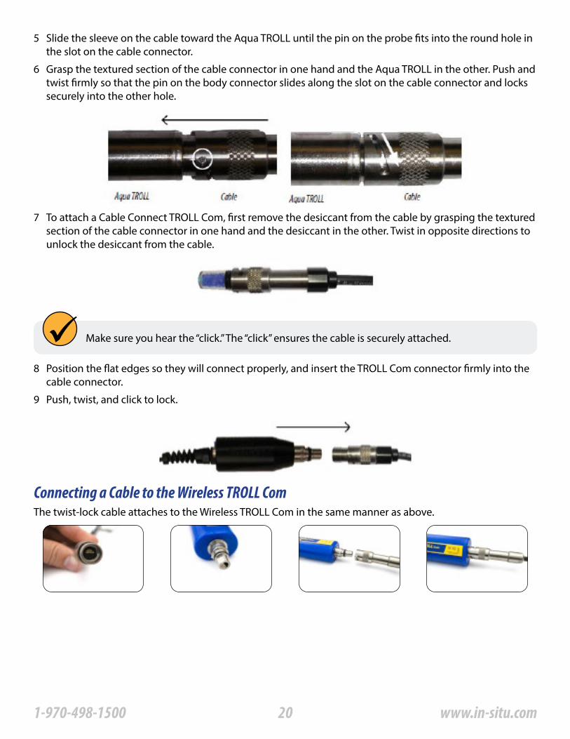
5 Slide the sleeve on the cable toward the Aqua TROLL until the pin on the probe fits into the round hole in the slot on the cable connector�
6 Grasp the textured section of the cable connector in one hand and the Aqua TROLL in the other� Push and twist firmly so that the pin on the body connector slides along the slot on the cable connector and locks securely into the other hole�
7 To attach a Cable Connect TROLL Com, first remove the desiccant from the cable by grasping the textured section of the cable connector in one hand and the desiccant in the other� Twist in opposite directions to unlock the desiccant from the cable�
Make sure you hear the “click�” The “click” ensures the cable is securely attached�
8 Position the flat edges so they will connect properly, and insert the TROLL Com connector firmly into the cable connector�
9 Push, twist, and click to lock�
Connecting a Cable to the Wireless TROLL ComThe twist-lock cable attaches to the Wireless TROLL Com in the same manner as above�
201-970-498-1500 www.in-situ.com
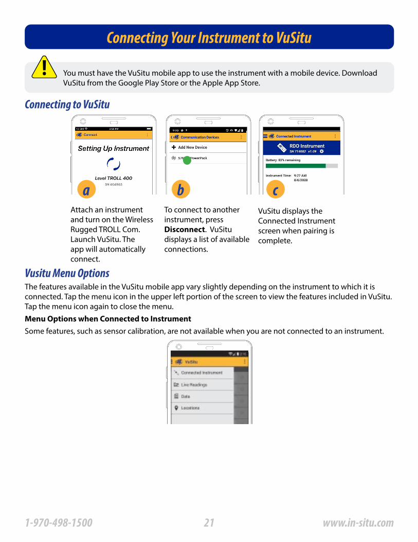
Connecting Your Instrument to VuSitu
The features available in the VuSitu mobile app vary slightly depending on the instrument to which it is connected� Tap the menu icon in the upper left portion of the screen to view the features included in VuSitu� Tap the menu icon again to close the menu�
Some features, such as sensor calibration, are not available when you are not connected to an instrument�
Vusitu Menu Options
Connecting to VuSitu
Menu Options when Connected to Instrument
You must have the VuSitu mobile app to use the instrument with a mobile device� Download VuSitu from the Google Play Store or the Apple App Store�
Attach an instrument and turn on the Wireless Rugged TROLL Com� Launch VuSitu� The app will automatically connect�
aTo connect to another instrument, press Disconnect� VuSitu displays a list of available connections�
bVuSitu displays the Connected Instrument screen when pairing is complete�
c
211-970-498-1500 www.in-situ.com
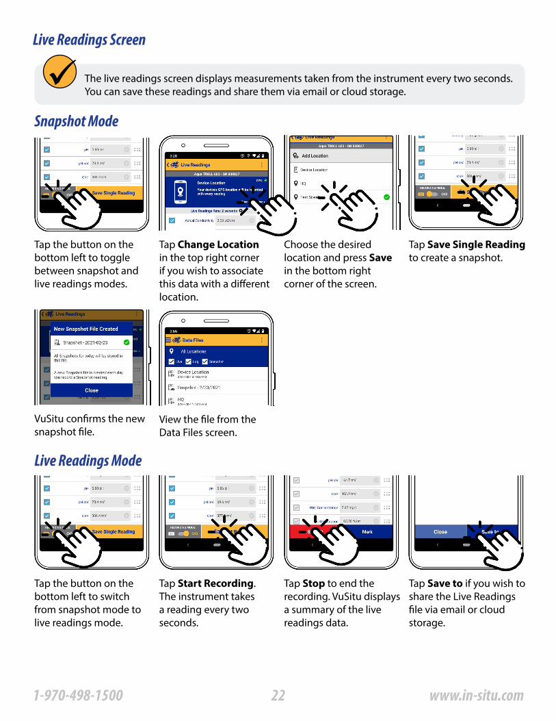
Live Readings Screen
Snapshot Mode
Tap the button on the bottom left to toggle between snapshot and live readings modes�
Tap Save Single Reading to create a snapshot�
Tap Change Location in the top right corner if you wish to associate this data with a different location�
View the file from the Data Files screen�
Choose the desired location and press Save in the bottom right corner of the screen�
VuSitu confirms the new snapshot file�
Live Readings Mode
Tap the button on the bottom left to switch from snapshot mode to live readings mode�
Tap Start Recording� The instrument takes a reading every two seconds�
Tap Stop to end the recording� VuSitu displays a summary of the live readings data�
Tap Save to if you wish to share the Live Readings file via email or cloud storage�
The live readings screen displays measurements taken from the instrument every two seconds� You can save these readings and share them via email or cloud storage�
221-970-498-1500 www.in-situ.com
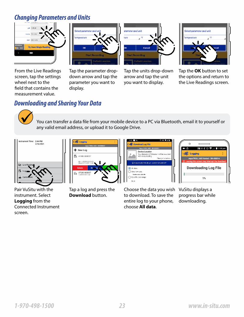
Changing Parameters and Units
Downloading and Sharing Your Data
You can transfer a data file from your mobile device to a PC via Bluetooth, email it to yourself or any valid email address, or upload it to Google Drive�
VuSitu displays a progress bar while downloading�
Choose the data you wish to download� To save the entire log to your phone, choose All data�
Pair VuSitu with the instrument� Select Logging from the Connected Instrument screen�
Tap a log and press the Download button�
From the Live Readings screen, tap the settings wheel next to the field that contains the measurement value�
Tap the parameter drop-down arrow and tap the parameter you want to display�
Tap the units drop-down arrow and tap the unit you want to display�
Tap the OK button to set the options and return to the Live Readings screen�
231-970-498-1500 www.in-situ.com
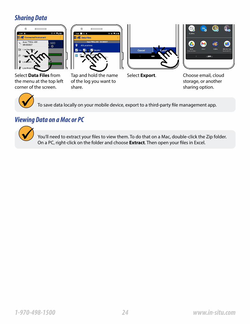
Sharing Data
Viewing Data on a Mac or PC
You’ll need to extract your files to view them� To do that on a Mac, double-click the Zip folder� On a PC, right-click on the folder and choose Extract� Then open your files in Excel�
Select Data Files from the menu at the top left corner of the screen�
Tap and hold the name of the log you want to share�
Select Export� Choose email, cloud storage, or another sharing option�
To save data locally on your mobile device, export to a third-party file management app�
241-970-498-1500 www.in-situ.com
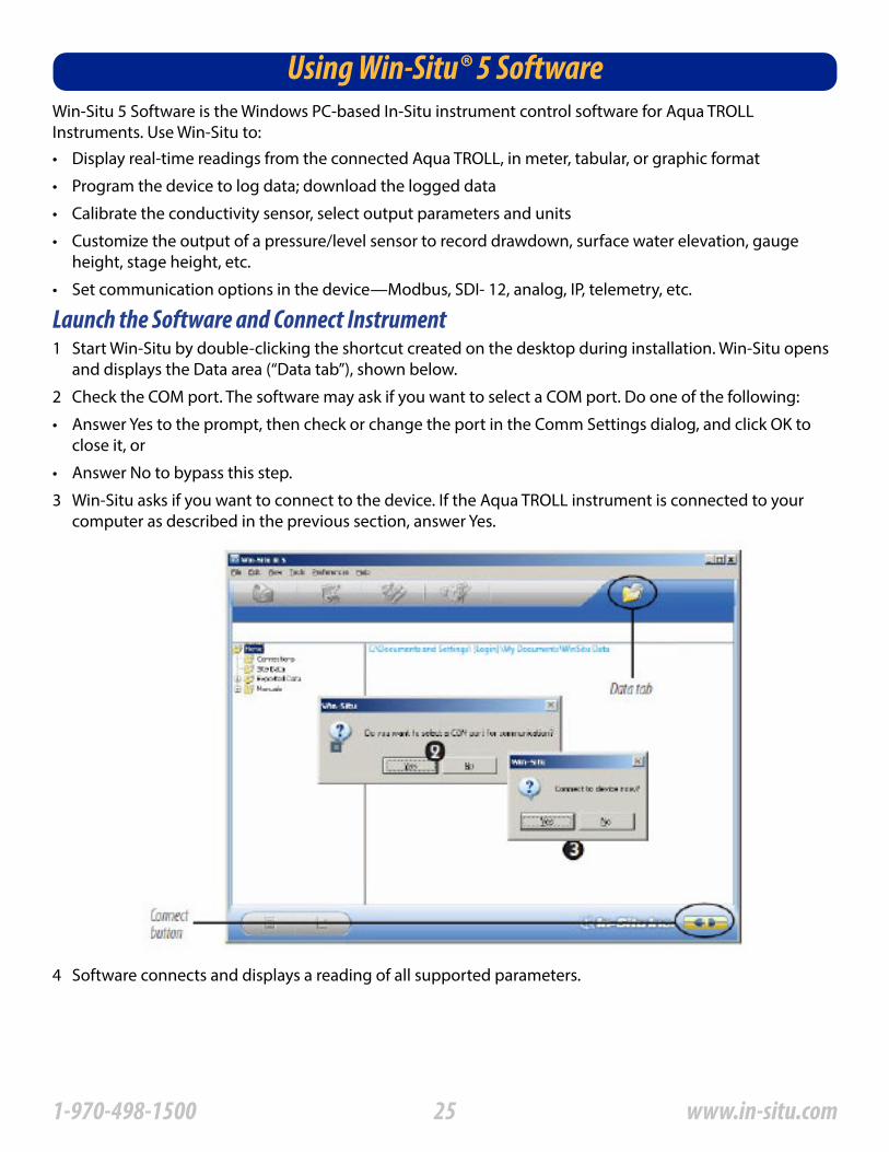
Win-Situ 5 Software is the Windows PC-based In-Situ instrument control software for Aqua TROLL Instruments� Use Win-Situ to:
1 Start Win-Situ by double-clicking the shortcut created on the desktop during installation� Win-Situ opens and displays the Data area (“Data tab”), shown below�
2 Check the COM port� The software may ask if you want to select a COM port� Do one of the following:
• Answer Yes to the prompt, then check or change the port in the Comm Settings dialog, and click OK to close it, or
• Answer No to bypass this step�
3 Win-Situ asks if you want to connect to the device� If the Aqua TROLL instrument is connected to your computer as described in the previous section, answer Yes�
Launch the Software and Connect Instrument
• Display real-time readings from the connected Aqua TROLL, in meter, tabular, or graphic format
• Program the device to log data; download the logged data
• Calibrate the conductivity sensor, select output parameters and units
• Customize the output of a pressure/level sensor to record drawdown, surface water elevation, gauge height, stage height, etc�
• Set communication options in the device—Modbus, SDI- 12, analog, IP, telemetry, etc�
4 Software connects and displays a reading of all supported parameters�
Using Win-Situ® 5 Software
251-970-498-1500 www.in-situ.com
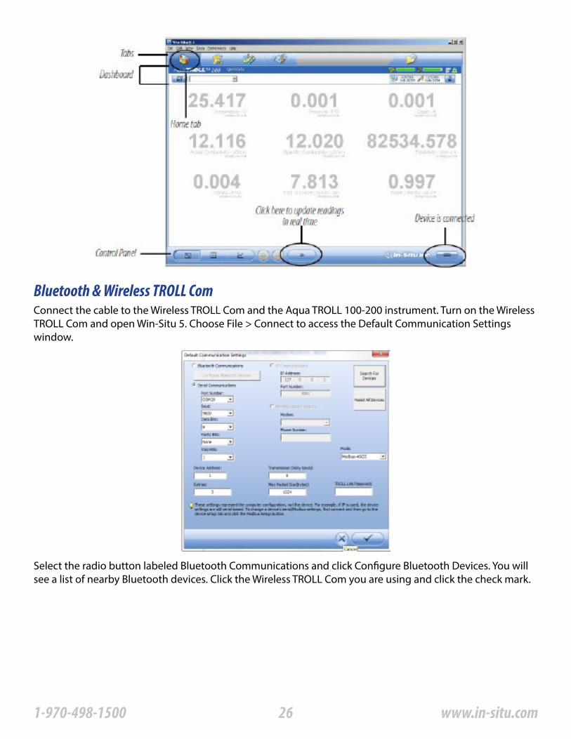
Bluetooth & Wireless TROLL ComConnect the cable to the Wireless TROLL Com and the Aqua TROLL 100-200 instrument� Turn on the Wireless TROLL Com and open Win-Situ 5� Choose File > Connect to access the Default Communication Settings window�
Select the radio button labeled Bluetooth Communications and click Configure Bluetooth Devices� You will see a list of nearby Bluetooth devices� Click the Wireless TROLL Com you are using and click the check mark�
261-970-498-1500 www.in-situ.com
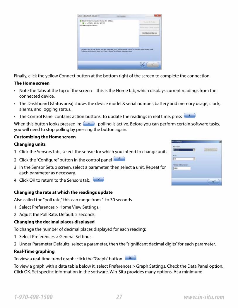
Finally, click the yellow Connect button at the bottom right of the screen to complete the connection�
The Home screen
Changing units
Customizing the Home screen
Changing the rate at which the readings update
Changing the decimal places displayed
Real-Time graphing
• Note the Tabs at the top of the screen—this is the Home tab, which displays current readings from the connected device�
• The Dashboard (status area) shows the device model & serial number, battery and memory usage, clock, alarms, and logging status�
• The Control Panel contains action buttons� To update the readings in real time, press
When this button looks pressed in: polling is active� Before you can perform certain software tasks, you will need to stop polling by pressing the button again�
Also called the “poll rate,” this can range from 1 to 30 seconds�
To change the number of decimal places displayed for each reading:
To view a real-time trend graph: click the “Graph” button�
To view a graph with a data table below it, select Preferences > Graph Settings� Check the Data Panel option� Click OK� Set specific information in the software� Win-Situ provides many options� At a minimum:
1 Click the Sensors tab , select the sensor for which you intend to change units�
2 Click the “Configure” button in the control panel
3 In the Sensor Setup screen, select a parameter, then select a unit� Repeat for each parameter as necessary�
4 Click OK to return to the Sensors tab�
1 Select Preferences > Home View Settings�
2 Adjust the Poll Rate� Default: 5 seconds�
1 Select Preferences > General Settings�
2 Under Parameter Defaults, select a parameter, then the “significant decimal digits” for each parameter�
271-970-498-1500 www.in-situ.com
• Set the Aqua TROLL clock�
• Enter a name for the site where the instrument will collect data�
• Calibrate the conductivity sensor�
• Enter data logging instructions�
A brief overview is provided here� For more detailed information, see the Win-Situ Help menu�
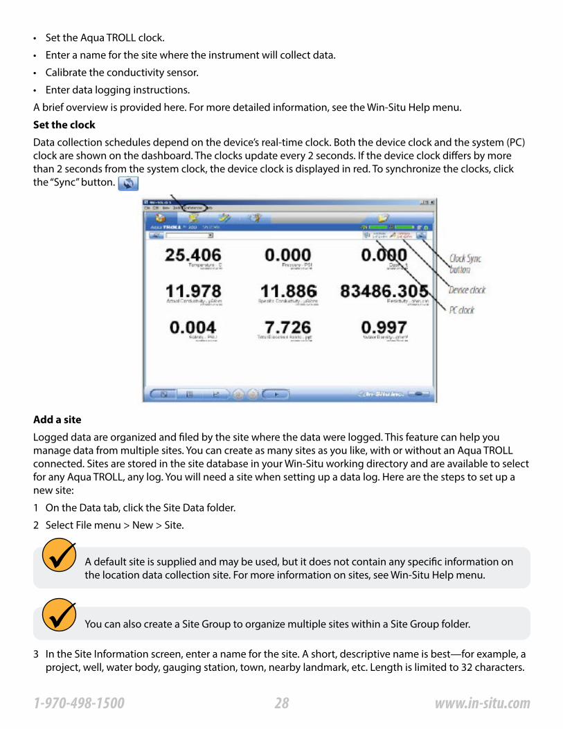
Data collection schedules depend on the device’s real-time clock� Both the device clock and the system (PC) clock are shown on the dashboard� The clocks update every 2 seconds� If the device clock differs by more than 2 seconds from the system clock, the device clock is displayed in red� To synchronize the clocks, click the “Sync” button�
Logged data are organized and filed by the site where the data were logged� This feature can help you manage data from multiple sites� You can create as many sites as you like, with or without an Aqua TROLL connected� Sites are stored in the site database in your Win-Situ working directory and are available to select for any Aqua TROLL, any log� You will need a site when setting up a data log� Here are the steps to set up a new site:
Set the clock
Add a site
1 On the Data tab, click the Site Data folder�
2 Select File menu > New > Site�
A default site is supplied and may be used, but it does not contain any specific information on the location data collection site� For more information on sites, see Win-Situ Help menu�
You can also create a Site Group to organize multiple sites within a Site Group folder�
3 In the Site Information screen, enter a name for the site� A short, descriptive name is best—for example, a project, well, water body, gauging station, town, nearby landmark, etc� Length is limited to 32 characters�
281-970-498-1500 www.in-situ.com
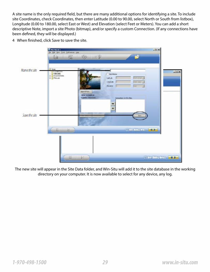
A site name is the only required field, but there are many additional options for identifying a site� To include site Coordinates, check Coordinates, then enter Latitude (0�00 to 90�00, select North or South from listbox), Longitude (0�00 to 180�00, select East or West) and Elevation (select Feet or Meters)� You can add a short descriptive Note, import a site Photo (bitmap), and/or specify a custom Connection� (If any connections have been defined, they will be displayed�)
4 When finished, click Save to save the site�
The new site will appear in the Site Data folder, and Win-Situ will add it to the site database in the working directory on your computer� It is now available to select for any device, any log�
291-970-498-1500 www.in-situ.com
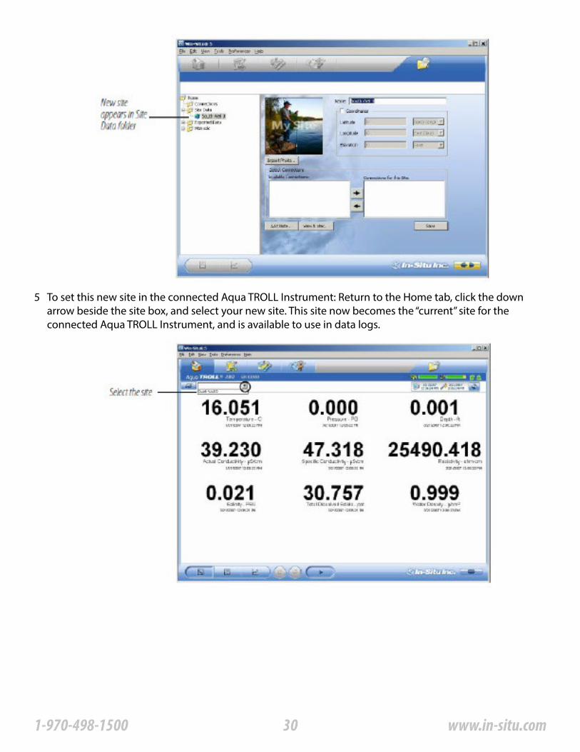
5 To set this new site in the connected Aqua TROLL Instrument: Return to the Home tab, click the down arrow beside the site box, and select your new site� This site now becomes the “current” site for the connected Aqua TROLL Instrument, and is available to use in data logs�
301-970-498-1500 www.in-situ.com
Check the Conductivity Calibration
Prepare to Log Data
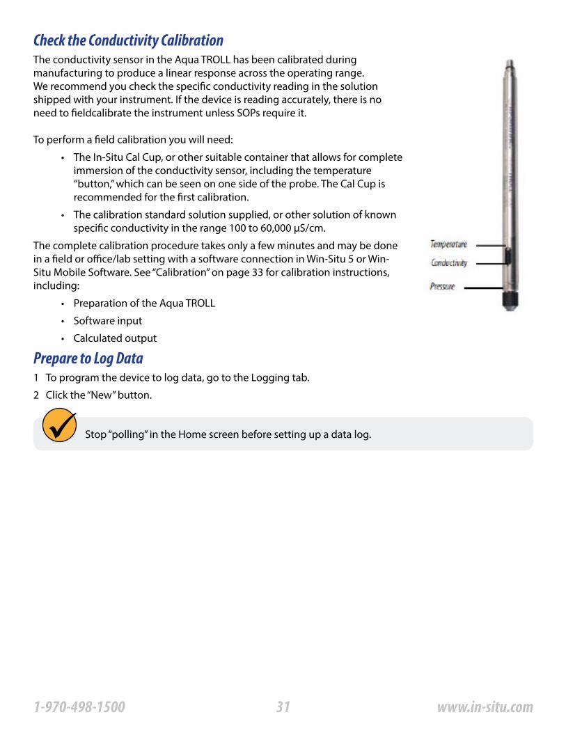
The conductivity sensor in the Aqua TROLL has been calibrated during manufacturing to produce a linear response across the operating range�We recommend you check the specific conductivity reading in the solution shipped with your instrument� If the device is reading accurately, there is no need to fieldcalibrate the instrument unless SOPs require it�
To perform a field calibration you will need:
The complete calibration procedure takes only a few minutes and may be done in a field or office/lab setting with a software connection in Win-Situ 5 or Win-Situ Mobile Software� See “Calibration” on page 33 for calibration instructions, including:
• The In-Situ Cal Cup, or other suitable container that allows for complete immersion of the conductivity sensor, including the temperature “button,” which can be seen on one side of the probe� The Cal Cup is recommended for the first calibration�
• The calibration standard solution supplied, or other solution of known specific conductivity in the range 100 to 60,000 μS/cm�
• Preparation of the Aqua TROLL
• Software input
• Calculated output
1 To program the device to log data, go to the Logging tab�
2 Click the “New” button�
Stop “polling” in the Home screen before setting up a data log�
311-970-498-1500 www.in-situ.com
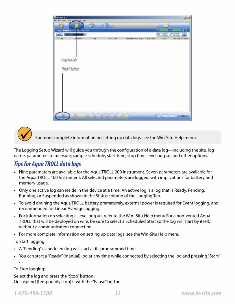
For more complete information on setting up data logs, see the Win-Situ Help menu�
The Logging Setup Wizard will guide you through the configuration of a data log—including the site, log name, parameters to measure, sample schedule, start time, stop time, level output, and other options�
To Start logging:
To Stop logging:
Tips for Aqua TROLL data logs• Nine parameters are available for the Aqua TROLL 200 Instrument� Seven parameters are available for
the Aqua TROLL 100 Instrument� All selected parameters are logged, with implications for battery and memory usage�
• Only one active log can reside in the device at a time� An active log is a log that is Ready, Pending, Running, or Suspended as shown in the Status column of the Logging Tab�
• To avoid draining the Aqua TROLL battery prematurely, external power is required for Event logging, and recommended for Linear Average logging�
• For information on selecting a Level output, refer to the Win- Situ Help menu�For a non-vented Aqua TROLL that will be deployed on wire, be sure to select a Scheduled Start so the log will start by itself, without a communication connection�
• For more complete information on setting up data logs, see the Win-Situ Help menu �
• A “Pending” (scheduled) log will start at its programmed time�
• You can start a “Ready” (manual) log at any time while connected by selecting the log and pressing “Start” �
Select the log and press the “Stop” button �Or suspend (temporarily stop) it with the “Pause” button �
321-970-498-1500 www.in-situ.com

To Download the log to the connected PC:
To View the log after downloading:
You can import data files from VuSitu into Win-Situ 5 from the File menu�
• Select the log and press the “Download” button�
• Go to the Data tab and select the log; for a graph press�
Importing VuSitu Data to Win-Situ
A� Click File > Import VuSitu CSV in the menu bar at the top of the screen�
B� Select the file you wish to import and click Open�
331-970-498-1500 www.in-situ.com
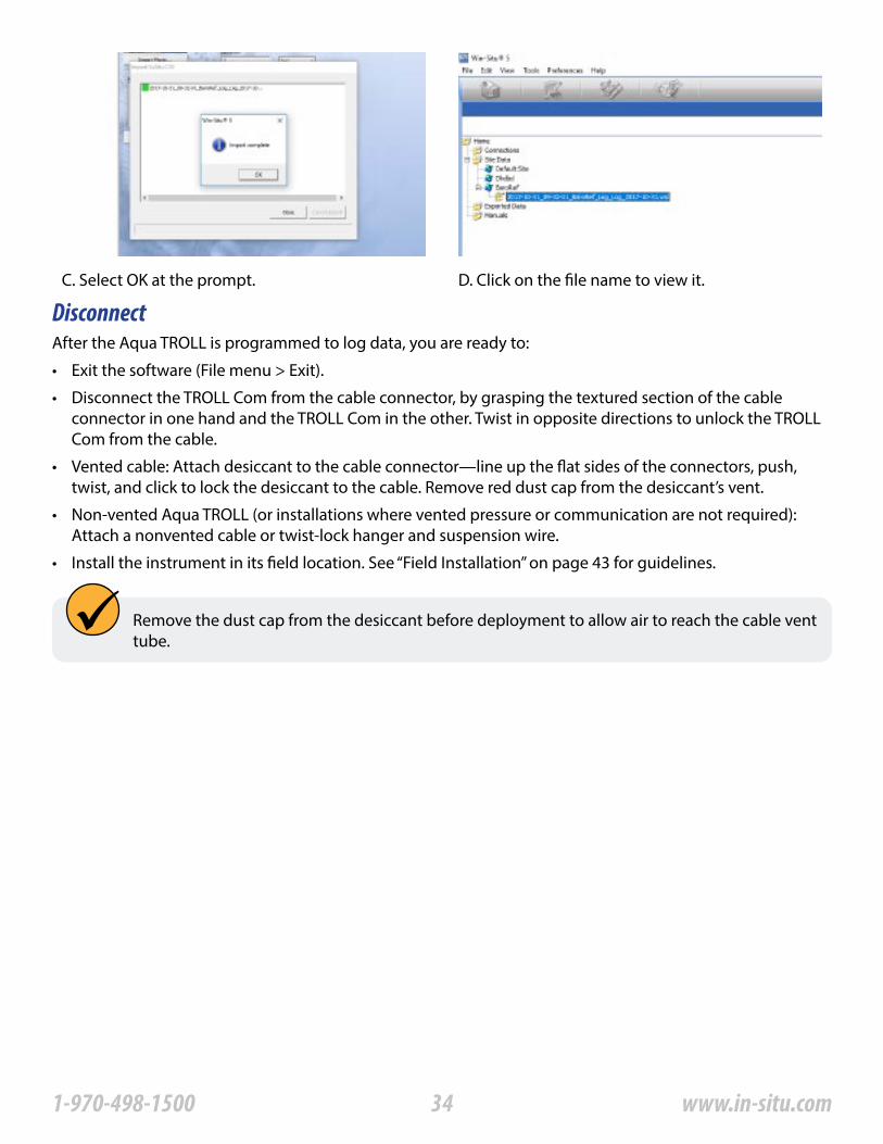
C� Select OK at the prompt� D� Click on the file name to view it�
DisconnectAfter the Aqua TROLL is programmed to log data, you are ready to:
• Exit the software (File menu > Exit)�
• Disconnect the TROLL Com from the cable connector, by grasping the textured section of the cable connector in one hand and the TROLL Com in the other� Twist in opposite directions to unlock the TROLL Com from the cable�
• Vented cable: Attach desiccant to the cable connector—line up the flat sides of the connectors, push, twist, and click to lock the desiccant to the cable� Remove red dust cap from the desiccant’s vent�
• Non-vented Aqua TROLL (or installations where vented pressure or communication are not required): Attach a nonvented cable or twist-lock hanger and suspension wire�
• Install the instrument in its field location� See “Field Installation” on page 43 for guidelines�
Remove the dust cap from the desiccant before deployment to allow air to reach the cable vent tube�
341-970-498-1500 www.in-situ.com
ConductivityAbout Conductivity
How is conductivity measured
Conductivity measures the ability of a material to carry an electric current� Generally, the higher the concentration of dissolved salts and minerals in water, the better the water is as a conductor, therefore the electrical conductivity is higher� Deionized/distilled water is a poor conductor because almost all anions and cations are removed during the deionization/distillation process� If conductivity changes in a body of water, it often indicates an environmental event� For example, a dramatic increase in the electrical conductivity of an underground fresh water aquifer located near the ocean could indicate the beginning of saltwater intrusion� On the other hand, an increase in the electrical conductivity of a small lake that is completely surrounded by farmland may simply be the result of runoff from recent precipitation�
Conductance is the reciprocal of the resistance, in ohms, measured between two opposing electrodes of a 1 cm cube at a specific temperature� The unit 1/ohm or mho was given the name of Siemens (S) for conductance� It is not practical to require all conductance cells to have the dimensions of an exact cube� To enable the comparison of data from experiments with different conductance cells, the conductance is multiplied by the cell constant to show conductivity in Siemens per centimeter (S/cm)� Cell constants are determined for each sensor using a standard solution of known conductivity� The cell constant depends on the electrode area and the amount of separation or distance between the electrodes�The four-electrode conductivity cell contains two drive electrodes and two sensing electrodes� In the Aqua TROLL instrument, each drive electrode is composed of two interconnected pins, for a total of six pins� The sensing electrodes are positioned in a low current area to minimize electrode fouling� An alternating current is used to drive the cell� This reduces errors caused by polarization resulting from the application of a direct current�
CalibrationThe conductivity sensor in the Aqua TROLL instrument has been calibrated during manufacturing to produce a linear response across the operating range� Standard Operating Procedures for measuring conductivity in the field typically specify that the sensor shall be calibrated before use, close to the expected temperature and conductivity conditions� The accuracy of the sensor depends on the calibration solution used and the operator’s technique�
We recommend that you check the specific conductivity reading in the solution shipped with your instrument� If the device is reading accurately, there is no need to field-calibrate the instrument unless SOPs require it�
The Aqua TROLL instrument can be calibrated at any point in the operating range� However, best results will be obtained in the range of approximately 100 to 60,000 microSiemens/cm (μS/ cm)�When carbon dioxide from the air dissolves into water it increases the conductivity, sometimes by as much as one or two μS/cm� This could shift a 146�9 standard by as much as 3%� The amount of shift is not predictable, so it should be minimized by limiting exposure to air� Fill the calibration cup to the marked fill line and close it as soon as possible� A small air bubble in the cup is acceptable, and in fact it assists mixing during the inversions� Discard remaining portions of low range calibration standards within a few days after opening the bottle�
351-970-498-1500 www.in-situ.com
Preparing to calibrate
To perform a conductivity calibration of the Aqua TROLL Instrument you will need:
• The In-Situ Cal Cup supplied with your instrument�
• The calibration standard solution supplied, or other solution of known specific conductivity in the range 100 to 60,000 μS/cm�
Three factors are essential to a successful conductivity calibration:• The calibration solution is not diluted or contaminated�
• The probe and the solution are at the same temperature�
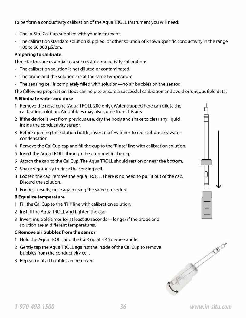
• The sensing cell is completely filled with solution—no air bubbles on the sensor�The following preparation steps can help to ensure a successful calibration and avoid erroneous field data�A Eliminate water and rinse1 Remove the nose cone (Aqua TROLL 200 only)� Water trapped here can dilute the
calibration solution� Air bubbles may also come from this area�
2 If the device is wet from previous use, dry the body and shake to clear any liquid inside the conductivity sensor�
3 Before opening the solution bottle, invert it a few times to redistribute any water condensation�
4 Remove the Cal Cup cap and fill the cup to the “Rinse” line with calibration solution�
5 Insert the Aqua TROLL through the grommet in the cap�
6 Attach the cap to the Cal Cup� The Aqua TROLL should rest on or near the bottom�
7 Shake vigorously to rinse the sensing cell�
8 Loosen the cap, remove the Aqua TROLL� There is no need to pull it out of the cap� Discard the solution�
9 For best results, rinse again using the same procedure�B Equalize temperature
C Remove air bubbles from the sensor
1 Fill the Cal Cup to the “Fill” line with calibration solution�
2 Install the Aqua TROLL and tighten the cap�
3 Invert multiple times for at least 30 seconds— longer if the probe and solution are at different temperatures�
1 Hold the Aqua TROLL and the Cal Cup at a 45 degree angle�
2 Gently tap the Aqua TROLL against the inside of the Cal Cup to remove bubbles from the conductivity cell�
3 Repeat until all bubbles are removed�
361-970-498-1500 www.in-situ.com
With the correct fill level, and the instrument held at a 45° angle, the air bubble in the Cal Cup will not intrude into the conductivity sensor�
Sometimes dissolved gases in the solution will cause bubbles to form on the sensor, especially if the solution is cold� Thermal equilibrium may require extra time, and air bubbles may need to be removed before starting the calibration� If you can see bubbles on the inside of the Cal Cup, bubbles are probably on the sensor�
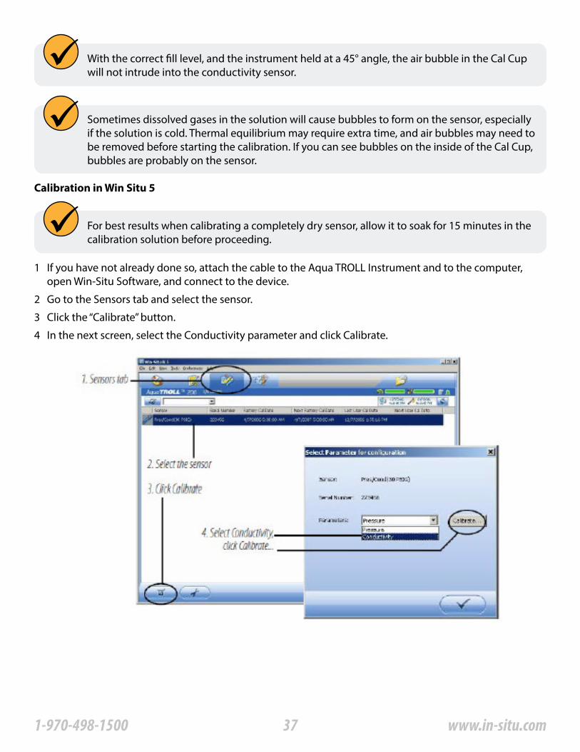
Calibration in Win Situ 5
For best results when calibrating a completely dry sensor, allow it to soak for 15 minutes in the calibration solution before proceeding�
1 If you have not already done so, attach the cable to the Aqua TROLL Instrument and to the computer, open Win-Situ Software, and connect to the device�
2 Go to the Sensors tab and select the sensor�
3 Click the “Calibrate” button�
4 In the next screen, select the Conductivity parameter and click Calibrate�
371-970-498-1500 www.in-situ.com
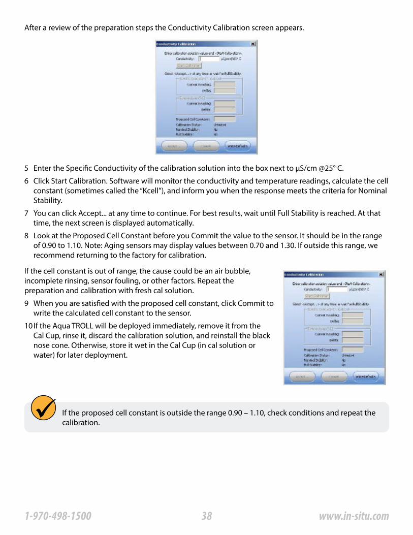
After a review of the preparation steps the Conductivity Calibration screen appears�
5 Enter the Specific Conductivity of the calibration solution into the box next to μS/cm @25° C�
6 Click Start Calibration� Software will monitor the conductivity and temperature readings, calculate the cell constant (sometimes called the “Kcell”), and inform you when the response meets the criteria for Nominal Stability�
7 You can click Accept��� at any time to continue� For best results, wait until Full Stability is reached� At that time, the next screen is displayed automatically�
8 Look at the Proposed Cell Constant before you Commit the value to the sensor� It should be in the range of 0�90 to 1�10� Note: Aging sensors may display values between 0�70 and 1�30� If outside this range, we recommend returning to the factory for calibration�
If the cell constant is out of range, the cause could be an air bubble, incomplete rinsing, sensor fouling, or other factors� Repeat the preparation and calibration with fresh cal solution�
9 When you are satisfied with the proposed cell constant, click Commit to write the calculated cell constant to the sensor�
10 If the Aqua TROLL will be deployed immediately, remove it from the Cal Cup, rinse it, discard the calibration solution, and reinstall the black nose cone� Otherwise, store it wet in the Cal Cup (in cal solution or water) for later deployment�
If the proposed cell constant is outside the range 0�90 – 1�10, check conditions and repeat the calibration�
381-970-498-1500 www.in-situ.com

Nominal Stability vs� Full Stability
Available parameters
Actual Conductivity
To meet the criteria for a valid calibration point, the change in sensor response is monitored over time� The software is looking for the calibration solution temperature and the sensor readings to settle over a specific time period� The criteria for Full Stability are designed to meet the published specifications� The criteria for Nominal Stability are designed to shorten the calibration time when an approximate calibration is acceptable�
The Aqua TROLL Instrument can also calculate and record derived parameters as listed below� For more information on measurement methodology, including the equations used to derive the calculated parameters, see the technical note “Aqua TROLL 200 Measurement Methodology” on the In-Situ software/resource CD, or on the In-Situ web site at www�In-Situ�com�
Units: micro siemens per centimeter (μS/cm), default milli siemens per centimeter (mS/cm)Specific conductivity
Salinity
Resistivity
Density of water
Total Dissolved Solids (TDS)
A means of expressing what the actual conductivity of a solution would be at a standard reference temperature (25° C)� Calculated from actual conductivity and temperature� The factory default coefficients calculate specific conductivity per Standard Methods 2510B�
Units: micro siemens per centimeter (μS/cm), default milli siemens per centimeter (mS/cm)
Calculated from specific conductivity using a conversion factor (Default: 0�65)�
The TDS conversion factor may be edited in Win-Situ as follows: Select the sensor on the Sensors tab and click Configure� In the next screen select the Total Dissolved Solids parameter and click Configure� Enter a value between 0�001 and 10�000� Units: parts per thousand (ppt), default parts per million (ppm)
Calculated from actual conductivity and temperature�Units: Practical Salinity Units (PSU)
Resistivity is the reciprocal (inverse) of the actual conductivity, which is useful when monitoring pure water� Units: ohms-cm
Calculated from salinity and temperature� Units: g/cm3
Parameter configuration is not available if the device is polling or has an active log�
Measured density values may be used to dynamically compute specific gravity when measuring Level� View Win-Situ Help or see “Pressure and Level” on page 38 of this manual for more information�
391-970-498-1500 www.in-situ.com
Shallow deploymentWhen deploying the Aqua TROLL Instrument in shallow water, bubble formation on the conductivity sensor can create false readings� We recommend the following to minimize the formation of bubbles:
Surface water: Gently agitate the instrument� Natural water flow will help to prevent bubbles�
Groundwater well or any location without flowing water, or where the instrument cannot be seen:1 Lower the Aqua TROLL until it is below the surface of the water� (Tip: This can be determined if not visible
by monitoring the pressure/depth readings�)
2 Allow the conductivity sensor to be thoroughly wetted (at least 30 seconds)�
3 Briskly agitate up and down several times, while not taking the device above the water surface�
4 When the conductivity readings stabilize, the Aqua TROLL is ready for deployment�
Maintenance and RecalibrationThe need to clean the sensor is determined by the site conditions, and the accuracy you want to obtain from the instrument� For example, when used in relatively clean water of low biological productivity, a conductivity sensor could maintain its accuracy specifications for several months� On the other hand, in water with a high potential for biological or mineral fouling, the sensor may need to be cleaned and re-calibrated more often� Visual inspection and measurement results are the best indicators that a device needs service recalibration�It is the user’s responsibility to develop and follow a maintenance program appropriate to the site� Most standard operating procedures (SOPs) instruct that the instrument be checked in a known standard at the end of a deployment� Calibration should always be checked after cleaning, and should be recalibrated when necessary�
Factory recalibration of the Aqua TROLL 200 Instrument should be performed every 12-18 months�
401-970-498-1500 www.in-situ.com

Non-vented (absolute) vs. vented (gauged) sensors
Pressure, Depth and Level
About the Pressure SensorThe Aqua TROLL 200 Instrument contains a pressure sensor� A pressure transducer senses changes in pressure, measured in force per square unit of surface area, exerted by water or other fluid on an internal media-isolated strain gauge� Common measurement units are pounds per square inch (psi) or newtons per square meter (pascals)�
A non-vented or “absolute” pressure sensor measures all pressure forces exerted on the strain gauge, including atmospheric pressure� Its units are psia (pounds per square inch “absolute”), measured with respect to zero pressure�
Non-vented pressure measurements are useful in vacuum testing, in short-term testing when atmospheric pressure would not be expected to change, in very deep aquifers where the effects of atmospheric pressure are negligible, and in unconfined aquifers that are open to the atmosphere�With vented or “gauged” pressure sensors, a vent tube in the cable applies atmospheric pressure to the back of the strain gauge� The basic unit for vented measurements is psig (pounds per square inch “gauge”), measured with respect to atmospheric pressure� Vented sensors thus exclude the atmospheric or barometric pressure component�
This difference between absolute and gauged measurements may be represented by a simple equation:Pgauge = Pabsolute - Patmosphere
Output options for pressure measurement are completely software-selectable� Each log configuration presents the following choices:
Pressure and Level
• Pressure in psi or kPa
• Depth in feet or meters
• Water Level with a reference (an “offset”)
• Surface Elevation: positive up
• Depth to Water (drawdown): positive downFor Depth and Level, the software presents additional options:• The type of measurement you intend to log (the “output”)
• The Level Reference you intend to use
• The specific gravity of the water in which the device will be deployed:
• Choose a fixed value for fresh, brackish, or saline water, or
• Enter a custom specific gravity value, or
• Choose Fixed density with gravitational compensation for a pressure-to-level conversion that compensates pressure readings for fluid density and local gravitational factor (based on your latitude and elevation), or
• Choose Dynamic density with gravitational compensation, which will allow the software to dynamically compute specific gravity using density measured by the conductivity sensor and local gravitational factor�
411-970-498-1500 www.in-situ.com
Configuring Depth and Level
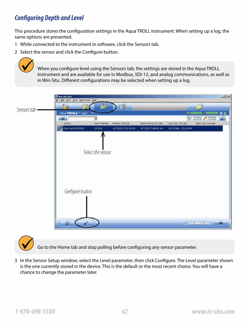
This procedure stores the configuration settings in the Aqua TROLL Instrument� When setting up a log, the same options are presented�1 While connected to the instrument in software, click the Sensors tab�
2 Select the sensor and click the Configure button�
When you configure level using the Sensors tab, the settings are stored in the Aqua TROLL Instrument and are available for use in Modbus, SDI-12, and analog communications, as well as in Win-Situ� Different configurations may be selected when setting up a log�
Go to the Home tab and stop polling before configuring any sensor parameter�
3 In the Sensor Setup window, select the Level parameter, then click Configure� The Level parameter shown is the one currently stored in the device� This is the default or the most recent choice� You will have a chance to change the parameter later�
421-970-498-1500 www.in-situ.com

Parameter configuration is not available if the device is polling or has an active log�
431-970-498-1500 www.in-situ.com
Pressure sensor accuracy can be adversely affected by improper care and handling, lightning strikes and similar surges, exceeding operating temperature and pressure limits, physical damage or abuse, as well as normal drift in the device’s electronic components� Aside from damage to the sensor, the need for factory recalibration is dependent upon the amount of drift a customer is willing to tolerate� Factory calibration every 12-18 months is recommended� Contact In-Situ Customer Service for information on the factory maintenance and calibration plan�
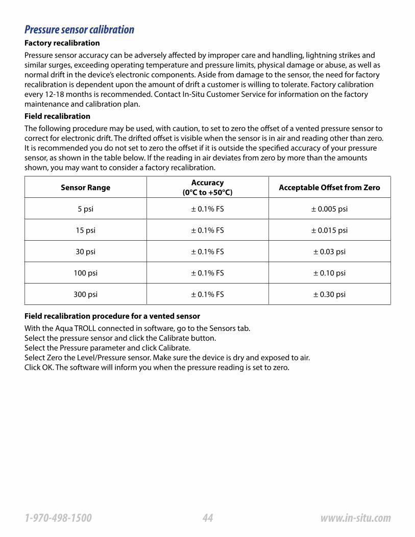
The following procedure may be used, with caution, to set to zero the offset of a vented pressure sensor to correct for electronic drift� The drifted offset is visible when the sensor is in air and reading other than zero� It is recommended you do not set to zero the offset if it is outside the specified accuracy of your pressure sensor, as shown in the table below� If the reading in air deviates from zero by more than the amounts shown, you may want to consider a factory recalibration�
Factory recalibration
Field recalibration
Sensor Range Accuracy(0°C to +50°C) Acceptable Offset from Zero
5 psi ± 0�1% FS ± 0�005 psi
15 psi ± 0�1% FS ± 0�015 psi
30 psi ± 0�1% FS ± 0�03 psi
100 psi ± 0�1% FS ± 0�10 psi
300 psi ± 0�1% FS ± 0�30 psi
Field recalibration procedure for a vented sensorWith the Aqua TROLL connected in software, go to the Sensors tab�Select the pressure sensor and click the Calibrate button�Select the Pressure parameter and click Calibrate�Select Zero the Level/Pressure sensor� Make sure the device is dry and exposed to air�Click OK� The software will inform you when the pressure reading is set to zero�
Pressure sensor calibration
441-970-498-1500 www.in-situ.com
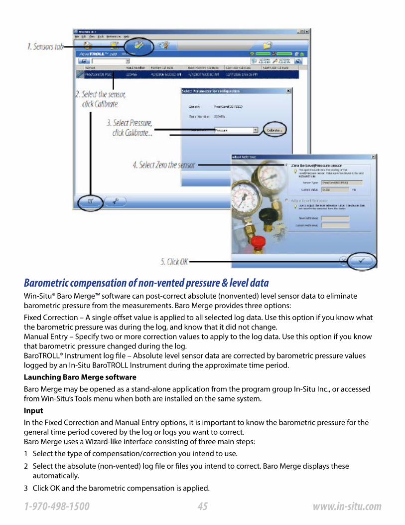
Barometric compensation of non-vented pressure & level dataWin-Situ® Baro Merge™ software can post-correct absolute (nonvented) level sensor data to eliminate barometric pressure from the measurements� Baro Merge provides three options:Fixed Correction – A single offset value is applied to all selected log data� Use this option if you know what the barometric pressure was during the log, and know that it did not change�Manual Entry – Specify two or more correction values to apply to the log data� Use this option if you know that barometric pressure changed during the log�BaroTROLL® Instrument log file – Absolute level sensor data are corrected by barometric pressure values logged by an In-Situ BaroTROLL Instrument during the approximate time period�Launching Baro Merge software
Input
Baro Merge may be opened as a stand-alone application from the program group In-Situ Inc�, or accessed from Win-Situ’s Tools menu when both are installed on the same system�
In the Fixed Correction and Manual Entry options, it is important to know the barometric pressure for the general time period covered by the log or logs you want to correct�Baro Merge uses a Wizard-like interface consisting of three main steps:1 Select the type of compensation/correction you intend to use�
2 Select the absolute (non-vented) log file or files you intend to correct� Baro Merge displays these automatically�
3 Click OK and the barometric compensation is applied�
451-970-498-1500 www.in-situ.com
Output
The original log file is not changed� A new, corrected log file with the same name and path is created� The original “�wsl” extension is replaced by “-BaroMerge�wsl”�
For help on using Win-Situ Baro Merge, press F1 at any Baro Merge screen�
For more detailed information on barometric compensation, see the technical notes on the In-Situ software/resource CD, or www� in-situ�com�
461-970-498-1500 www.in-situ.com
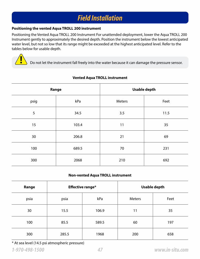
Field InstallationPositioning the vented Aqua TROLL 200 instrument
Positioning the Vented Aqua TROLL 200 Instrument For unattended deployment, lower the Aqua TROLL 200 Instrument gently to approximately the desired depth� Position the instrument below the lowest anticipated water level, but not so low that its range might be exceeded at the highest anticipated level� Refer to the tables below for usable depth�
Do not let the instrument fall freely into the water because it can damage the pressure sensor�
Vented Aqua TROLL instrument
Range Usable depth
psig kPa Meters Feet
5 34�5 3�5 11�5
15 103�4 11 35
30 206�8 21 69
100 689�5 70 231
300 2068 210 692
Non-vented Aqua TROLL instrument
Range Effective range* Usable depth
psia psia kPa Meters Feet
30 15�5 106�9 11 35
100 85�5 589�5 60 197
300 285�5 1968 200 658
* At sea level (14�5 psi atmospheric pressure)
471-970-498-1500 www.in-situ.com
Check instrument depth
At this point, if convenient, you can connect the Aqua TROLL 200 to a PC, launch the software, and take a reading� If the instrument is at the desired depth, secure it in position as suggested below, or reposition as necessary�
If you set the software to “Remind me later” to set a Level Reference, enter the level reference after installation when prompted�
481-970-498-1500 www.in-situ.com

Secure the cable
The RuggedCable includes a Kellems® grip near the surface end� You can slide it along the cable to the desired position by compressing it� When you pull on it, the grip tightens and stops sliding� You may need to pull on both ends of the Kellems grip to properly tighten it and keep it from slipping�
Use the loop of the Kellems grip to anchor the cable to a convenient stationary object� It works well with In-Situ’s well dock installation ring� Simply insert the loop into the locking clip on the well dock, and position the assembly on the top of a well�
• Never let a probe fall freely down a well� The resulting shock wave when it hits the water surface can damage the strain gauge�
• Check the level of water above the probe, then move it and read again to be sure that the probe presents a reasonable reading and shows change� It might not be located where you think it is� For example, it could be wedged against the casing with a loop of cable hanging below it� A probe in such a position might become dislodged and move while logging, giving a false change in level� A secure placement is critical to accurate measurements�
• Do not allow the vented cable to kink or bend� If the internal vent tube is obstructed, water level measurements can be adversely affected� The recommended minimum bend radius is 13�5 mm (0�54 in), which is twice the cable diameter� The minimum bend radius for vented cable is 13�5 mm (0�54 in)�
• For accurate measurements, the instrument should remain immobile while logging data�
• Be sure the uphole cable end is capped—desiccant on the vented cable connector, soft dust cap on non-vented cable— and positioned above the highest anticipated water level� Avoid areas that may flood when using vented cable�
Installation tips
The minimum bend radius for vented cable is 13�5 mm (0�54 in)�
Do not submerge the cable connector; do not immerse in any fluid�
Be sure to replace the desiccant before it appears pink� Expired desiccant can allow moisture build up in the vent tube, causing a blockage resulting in inaccurate data�
491-970-498-1500 www.in-situ.com
Do not deploy pressure transducers such that ice may form on or near the sensor or cable connections� Ice formation is a powerful expansive force and may over-pressurize the sensor or
otherwise cause damage� Any damage associated with ice formation is not covered by warranty�
Stabilization Time
Shallow Deployment
Installation of a Non-Vented Aqua Troll
Allow the Aqua TROLL Instrument to stabilize to the water conditions for about an hour before logging data� A generous stabilization time is always desirable, especially in long-term deployments� Even though the cable is shielded, temperature stabilization and stretching can cause apparent changes in the level reading� A completely dry conductivity sensor may need a few minutes settling time after initial immersion� If you expect to monitor conductivity and water levels at the highest accuracy possible for the instrument, allow stabilization time�
When deploying the Aqua TROLL Instrument in shallow water, bubble formation on the conductivity sensor can create false readings� We recommend the following to minimize the formation of bubbles:
Surface water: Gently agitate the instrument� Natural water flow will help to prevent bubbles�
Groundwater well or any location without flowing water, or where the instrument cannot be seen:
1 Lower the Aqua TROLL until it is below the surface of the water� (Tip: This can be determined if not visible by monitoring the pressure/depth readings�)
2 Allow the conductivity sensor to be thoroughly wetted (at least 30 seconds)�
3 Briskly agitate up and down several times, while not taking the device above the water surface�
4 When the conductivity readings stabilize, the Aqua TROLL is ready for deployment�
Aqua TROLL 100 and non-vented Aqua TROLL 200 instruments do not require vented cable for proper operation� They may be deployed on non-vented RuggedCable or with a twist-lock hanger and stainless steel suspension wire�
• Because the twist-lock hanger has no communication capabilities, program the Aqua TROLL in advance, and download the data the same way�
• Logged pressure data will show the effects of changes in barometric pressure (unlike vented Aqua TROLL 200 sensors)� However, post-processing tools such as Win- Situ Baro Merge may be used to eliminate the effects of barometric pressure changes from the data, if required�
Be sure to program a non-vented Aqua TROLL before attaching the twist-lock hanger, as this accessory has no communication capability�
DO NOT submerge a non-vented Aqua TROLL without first attaching a twist-lock hanger, or a cable, because the unit could be damaged by flooding�
501-970-498-1500 www.in-situ.com
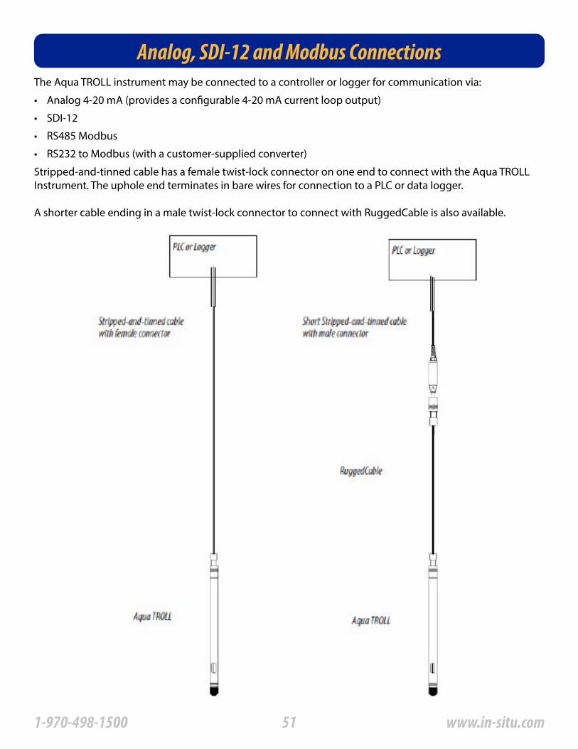
Analog, SDI-12 and Modbus ConnectionsThe Aqua TROLL instrument may be connected to a controller or logger for communication via:
• Analog 4-20 mA (provides a configurable 4-20 mA current loop output)
• SDI-12
• RS485 Modbus
• RS232 to Modbus (with a customer-supplied converter)
Stripped-and-tinned cable has a female twist-lock connector on one end to connect with the Aqua TROLL Instrument� The uphole end terminates in bare wires for connection to a PLC or data logger�
A shorter cable ending in a male twist-lock connector to connect with RuggedCable is also available�
511-970-498-1500 www.in-situ.com
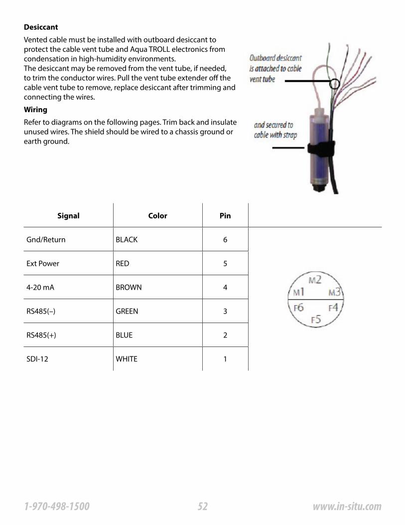
Desiccant
Wiring
Vented cable must be installed with outboard desiccant to protect the cable vent tube and Aqua TROLL electronics from condensation in high-humidity environments�The desiccant may be removed from the vent tube, if needed, to trim the conductor wires� Pull the vent tube extender off the cable vent tube to remove, replace desiccant after trimming and connecting the wires�
Refer to diagrams on the following pages� Trim back and insulate unused wires� The shield should be wired to a chassis ground or earth ground�
Signal Color Pin
Gnd/Return BLACK 6
Ext Power RED 5
4-20 mA BROWN 4
RS485(–) GREEN 3
RS485(+) BLUE 2
SDI-12 WHITE 1
521-970-498-1500 www.in-situ.com

531-970-498-1500 www.in-situ.com

541-970-498-1500 www.in-situ.com
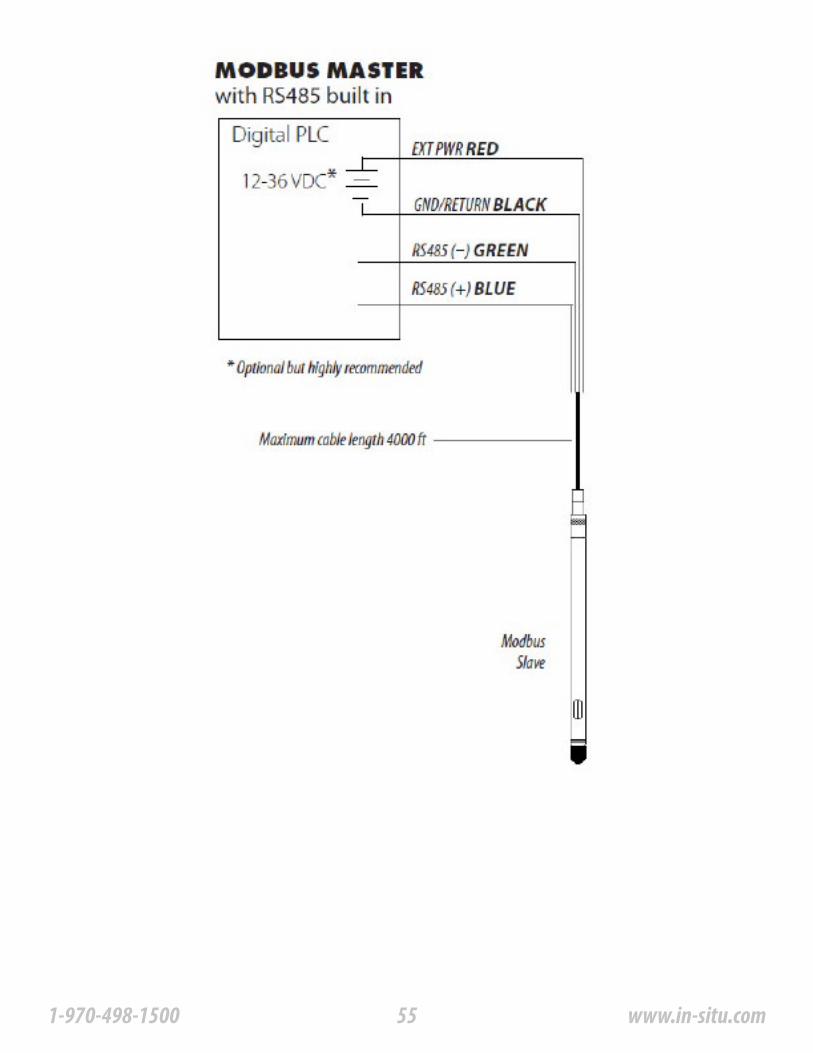
551-970-498-1500 www.in-situ.com
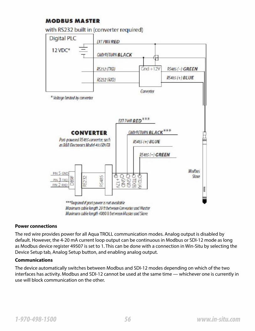
Power connections
Communications
The red wire provides power for all Aqua TROLL communication modes� Analog output is disabled by default� However, the 4-20 mA current loop output can be continuous in Modbus or SDI-12 mode as long as Modbus device register 49507 is set to 1� This can be done with a connection in Win-Situ by selecting the Device Setup tab, Analog Setup button, and enabling analog output�
The device automatically switches between Modbus and SDI-12 modes depending on which of the two interfaces has activity� Modbus and SDI-12 cannot be used at the same time — whichever one is currently in use will block communication on the other�
561-970-498-1500 www.in-situ.com
Using Win-Situ software
Redundant logging feature
For more information
Win-Situ provides options for configuring analog/SDI-12 communications (Setup tab) and Modbus communications (File menu > Settings)� In addition, the Aqua TROLL Instrument is capable of internal logging (programmed in Win-Situ) while participating in a Modbus, SDI-12, or analog network� However, Win-Situ cannot communicate with the Aqua TROLL Instrument while it is transmitting Modbus, SDI-12, or analog data, and conversely, the instrument cannot receive or respond to Modbus, SDI-12, or analog commands while connected to a PC serial port�
A port-powered RS485 converter like that shown for Modbus connections may be used for temporary connection of the Aqua TROLL to a serial port on a PC�
• SDI-12 Commands and Aqua TROLL Responses�• In-Situ Modbus Communication Protocol�
For additional information on Modbus and SDI-12 communications, including the SDI-12 commands and Modbus registers, see these In-Situ technical notes:
They are available on the In-Situ software/resource CD and at www�in-situ�com�
• If the PLC or recorder somehow loses data, the Aqua TROLL data can be retrieved using Win-Situ�
• If the PLC or recorder ceases to function due to power loss, the Aqua TROLL will continue to collect data using its own internal batteries and clock�
571-970-498-1500 www.in-situ.com
Care and MaintenanceOperating Considerations
Storage
General Maintenance
The Aqua TROLL Instrument has been designed to withstand harsh field conditions� However, as with any electronic instrument, it can be permanently damaged if used outside its operating specifications�
The Aqua TROLL 200 Instrument can withstand pressures of up to two times (2X) the rated range of the pressure sensor without damage, although it may not read correctly at such pressure� If the pressure range is exceeded by 3X, the pressure sensor will be destroyed�
Accuracy can be adversely affected by improper care and handling, lightning strikes and similar surges, exceeding operating temperature and pressure limits, physical damage or abuse� Factory calibration every 12-18 months is recommended� Contact In-Situ Customer Service for information on the factory maintenance and calibration plan�
Place the protective red dust cap on the cable end, or store with cable attached to protect the connector pins and O-ring� Store the instrument where it will not fall onto a hard surface� Protect the instrument from temperature extremes� Store within a temperature range of -40° C to 65° C (-40° F to 149° F)� For best performance if stored dry, soak the conductivity cell in a calibration standard for 48 hours prior to calibration and deployment�
Keep the pins on all connectors free of dirt and moisture by using the soft protective dust cap when cable is not attached to an instrument�
Vented cable ensures that atmospheric pressure is the reference pressure to the vented pressure sensor diaphragm� The vent tube should not be blocked, kinked, or otherwise obstructed� Such obstructions will cause barometric pressure to appear in measurements, and errors will be introduced due to thermal expansion and contraction of air within the vent tube and probe�
The Aqua TROLL temperature sensor operates within a temperature range of -5° to 50° C (23° to 122° F) in non-freezing fluid�
Temperature
Pressure range
Factory calibration
Twist-lock connectors
Cable vent tube (vented cable)
Do not submerge the cable connector; do not immerse in any fluid�
The recommended minimum bend radius is 13�5 mm (0�54 in), which is twice the cable diameter�
581-970-498-1500 www.in-situ.com

Be sure to replace the desiccant before it appears pink� Expired desiccant can allow moisture build up in the vent tube, causing a blockage resulting in inaccurate data�
Batteries
Cleaning
Internal batteries in the Aqua TROLL Instrument are not user replaceable� The approximate percentage remaining is displayed on the Win-Situ 5 Dashboard when the instrument is connected�
Clean the Aqua TROLL with water and a soft brush or plastic scouring pad, or soak overnight in a mild acidic solution, such as household vinegar�
If the pressure ports of the Aqua TROLL 200 in the front end are clogged with silt or mud, try the following:
To avoid damage to the pressure sensor diaphragm, do not insert any object into the sensor opening or attempt to dig out dirt or other materials� If contamination cannot be removed using the recommendations above, please contact In-Situ Inc� for cleaning�
If contamination cannot be removed using the recommendations above, please contact In-Situ Inc� for cleaning�
• Agitate the instrument vigorously in a bucket of clean water�
• Apply a gentle stream of water from a wash bottle�
• ln severe cases, remove the nose cone and clean out the holes with a soft brush or pipe cleaner�
Probe and front end
Damage caused by digging or scraping in the pressure sensor opening to remove silt, mud, etc� is not covered by the warranty�
When the nose cone is removed from the Aqua TROLL 200, the sensitive pressure sensor diaphragm is completely exposed� Do not touch this area with any object� Replace the nose cone as soon as possible�
591-970-498-1500 www.in-situ.com
Conductivity SensorFouling from mineral and biological sources can alter the sensor’s response�
• Rinse under running water to remove loose material�
• Always finish with a rinse in clean water�
• After cleaning, always check the calibration before redeployment, and recalibrate the sensor when necessary�
Acceptable cleaning processes fall into the following categories:
Process 1: Light scrubbing with a soft swab and mild soap such as a dilute solution of dish detergent� Be careful not to damage the plastic material of the conductivity cell� Aqua TROLL Instruments are shipped with polyurethane foam swabs for this purpose� You can also clean the conductivity cell using a thin cotton pipe cleaner and a a gentle back-and-forth motion�
Process 2: Light scrubbing with a foam swab and an aggressive soap such as Alconox detergent can be used for more stubborn deposits�
Process 3: Dilute (10:1) acetic acid, or consumer-packaged white vinegar, can be used to pre-soften calcium deposits� Follow this with Process 1 or Process 2, depending on the degree of residual contamination� The Aqua TROLL can soak for any length of time in dilute acetic acid� If this does not completely remove the material, try Process 4�
Process 4: Dilute phosphoric acid (< 27%) or the consumer product Lime-A-Way® can be topically applied with a soft swab to remove iron or calcium deposits that remain after using Process 3� Do not soak for more than 10 minutes� Rinse well with water�If contamination cannot be removed using the recommendations above, please contact In-Situ Inc�
Foam swabs are shipped with the Aqua TROLL Instrument; replacements are available from In-Situ Inc� (Catalog No� 0056820)�
Alconox is available from In-Situ Inc� (Catalog No� 0029810)�
DO NOT SOAK in phosphoric acid or Lime-A-Way® for more than 10 minutes�
601-970-498-1500 www.in-situ.com
TroubleshootingTroubleshooting Connections
Troubleshooting Data Logs
Problem
Problem
Problem
Probable cause
Probable cause
Probable cause 1
Probable cause 2
Suggested remedy
Suggested remedy
Suggested remedy
Suggested remedy
Win-Situ 5 Software cannot connect to the Aqua TROLL instrument�
Real-time readings are in the wrong units�
Default units are being used�
Click the Sensors tab, select the sensor, click the Configure button, and select the desired units for each parameter in the Sensor Setup window� Click OK� Be sure to stop “polling” in the Home screen before selecting units�
Only one active log can reside in the device at a time—an active log is a log that is Ready, Pending, Running, or Suspended as shown in the Status column of the Logging Tab�
The device has its maximum number of logs already stored—although this is not a likely cause for the Aqua TROLL 200, which has a capacity of 50 logs�
Download, and then delete a log you are finished using� This will make room for an additional log on the device�
Stop or delete the log if possible� Alternatively, configure the new log after the active log is completed�
Cannot add a new log�
The wrong COM port is selected, communication settings are incompatible, batteries are low, or cable connections are loose or dirty�
• All cable connections are tight, connectors are clean and dry�
• The cable is securely attached to the instrument�
• The correct COM port is selected (select Preferences menu > Comm Settings to check this)�
• The communication settings in Win-Situ and in the Aqua TROLL match� To reset the device communication settings to the serial defaults, click “Reset all Devices” in the Comm Settings dialog (Preferences menu > Comm Settings)
• The internal battery has voltage remaining or external power is supplied�
Check the following:
611-970-498-1500 www.in-situ.com
Problem
Problem
Problem
Probable cause 1
Suggested remedy
Suggested remedy
Suggested remedy
Probable cause 2
Probable cause
Probable cause
Suggested remedy
New log exceeds available memory (message from software)�
The log as configured would exceed the device memory�
Edit the log and try these:
Cannot configure level or other parameters using the Configure button on the Sensors tab� The Sensor setup screen is shown, but the Configure��� button is dim�
The Aqua TROLL has an active log—a log that is Ready, Pending, Running, or Suspended as shown in the Status column of the Logging Tab� Only one active log can reside in the device at a time�
• Visually inspect the sensor for the presence of fouling (most likely conductive material, possibly a bio-film); clean as described in Section 9 of this manual�
• Ensure the calibration solution is not contaminated, mislabeled, or partially evaporated�
• Rinse the Aqua TROLL Instrument and the Cal Cup thoroughly with fresh calibration solution before calibrating�
Stop or delete the log if possible� Alternatively, configure parameters after the log is completed�
The Aqua TROLL is actively polling (continually updating real-time readings) in the Home tab�
The calculated cell constant (Kcell) is lower than the recommended range of 0�98 – 1�02�
Check the following and then repeat the calibration:
The electrical resistance of the calibration solution was lower than expected for the nominal value�
Return to the Home tab and stop real-time readings by clicking�
• Select a longer sampling interval�
• If available, select the Wrap data option (current data will overwrite older data when the memory is full)�
• For a log with a scheduled start, select None as the stop condition, or select a stop time that is closer to the start time�
Troubleshooting Parameter Configuration
Troubleshooting Conductivity Calibration
621-970-498-1500 www.in-situ.com
Problem
The calculated cell constant (Kcell) is higher than the recommended range of 0�98 – 1�02�
The electrical resistance of the calibration solution was higher than expected for the nominal value, or an air bubble was present in the sensing cell during calibration�
Check the following and then repeat the calibration:
• Visually inspect the sensor for the presence of fouling (most likely an obstructing material or organism); clean as described in Section 9 of this manual�
• Ensure the calibration solution is not contaminated, mislabeled, or partially diluted�
• Rinse the Aqua TROLL Instrument and the Cal Cup thoroughly with fresh calibration solution before calibrating�
• “Roll and tap” the Aqua TROLL Instrument in the Cal Cup to dispel air bubbles�
Probable cause
Probable cause
631-970-498-1500 www.in-situ.com
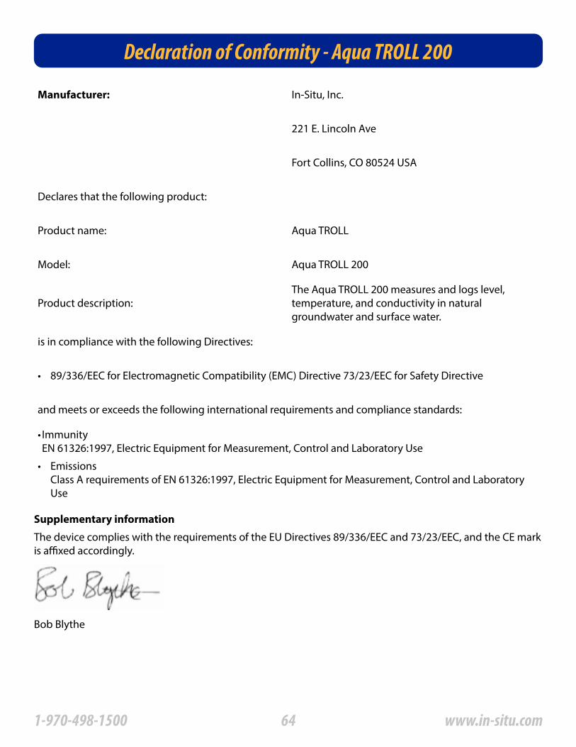
Declaration of Conformity - Aqua TROLL 200
Manufacturer: In-Situ, Inc�
221 E� Lincoln Ave
Fort Collins, CO 80524 USA
Declares that the following product:
Product name: Aqua TROLL
Model: Aqua TROLL 200
Product description:The Aqua TROLL 200 measures and logs level, temperature, and conductivity in natural groundwater and surface water�
is in compliance with the following Directives:
• 89/336/EEC for Electromagnetic Compatibility (EMC) Directive 73/23/EEC for Safety Directive
and meets or exceeds the following international requirements and compliance standards:
• Immunity EN 61326:1997, Electric Equipment for Measurement, Control and Laboratory Use
• Emissions Class A requirements of EN 61326:1997, Electric Equipment for Measurement, Control and Laboratory Use
Supplementary information
The device complies with the requirements of the EU Directives 89/336/EEC and 73/23/EEC, and the CE mark is affixed accordingly�
Bob Blythe
641-970-498-1500 www.in-situ.com
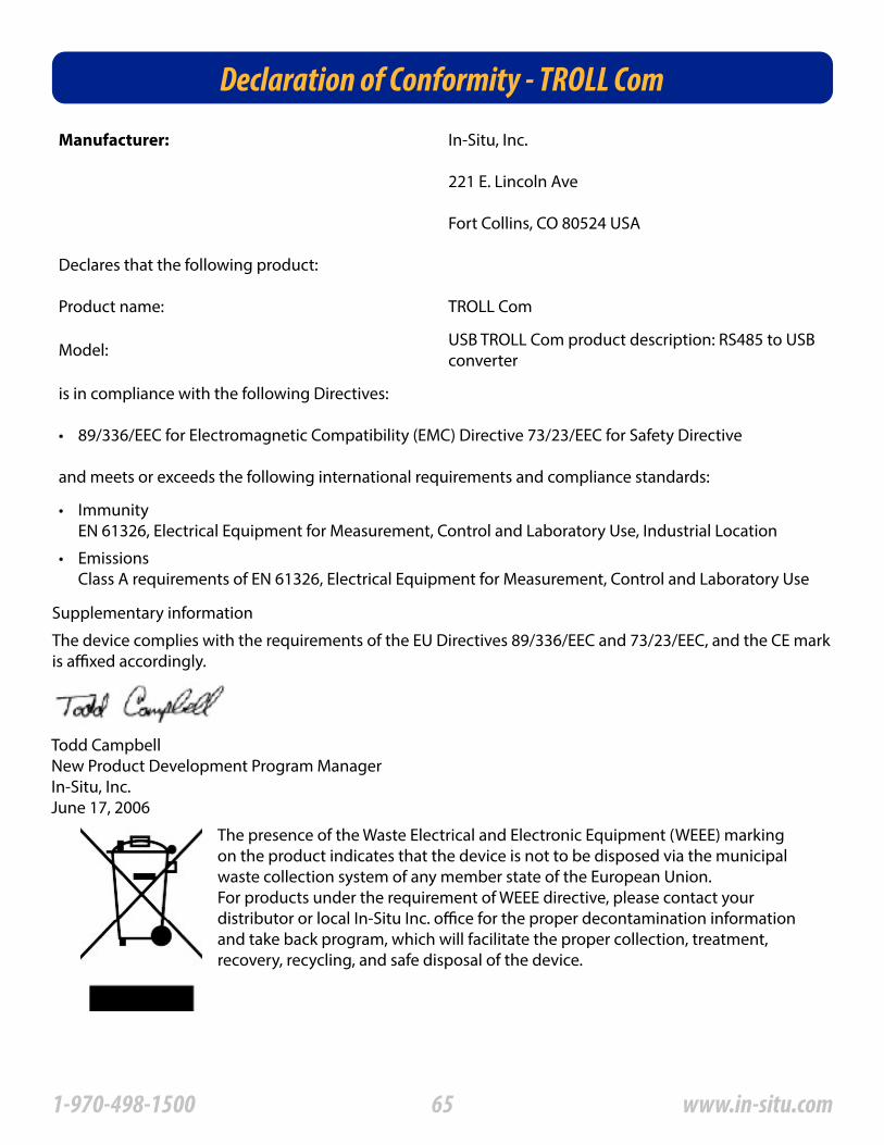
Declaration of Conformity - TROLL Com
Manufacturer: In-Situ, Inc�
221 E� Lincoln Ave
Fort Collins, CO 80524 USA
Declares that the following product:
Product name: TROLL Com
Model: USB TROLL Com product description: RS485 to USB converter
is in compliance with the following Directives:
• 89/336/EEC for Electromagnetic Compatibility (EMC) Directive 73/23/EEC for Safety Directive
and meets or exceeds the following international requirements and compliance standards:
• Immunity EN 61326, Electrical Equipment for Measurement, Control and Laboratory Use, Industrial Location
• Emissions Class A requirements of EN 61326, Electrical Equipment for Measurement, Control and Laboratory Use
Supplementary information
The device complies with the requirements of the EU Directives 89/336/EEC and 73/23/EEC, and the CE mark is affixed accordingly�
Todd CampbellNew Product Development Program ManagerIn-Situ, Inc�June 17, 2006
The presence of the Waste Electrical and Electronic Equipment (WEEE) marking on the product indicates that the device is not to be disposed via the municipal waste collection system of any member state of the European Union�For products under the requirement of WEEE directive, please contact your distributor or local In-Situ Inc� office for the proper decontamination information and take back program, which will facilitate the proper collection, treatment, recovery, recycling, and safe disposal of the device�
651-970-498-1500 www.in-situ.com
Related Documents