Operator's Manual Aqua TROLL ® 600 Multiparameter Sonde Part Number 0096400 Information subject to change without notice. In-Situ, In-Situ logo, Baro Merge, BaroTROLL, HERMIT, HydroVu™, iSitu, Pocket-Situ, RDO, RuggedCable, RuggedReader, SmarTROLL™, TROLL, VuSitu, and Win-Situ are trademarks or registered trademarks of In-Situ Inc. © 2016. All rights reserved. This product may be covered by patents identified at www.in-situ.com/patents 0096402 | 2018-11-16

Welcome message from author
This document is posted to help you gain knowledge. Please leave a comment to let me know what you think about it! Share it to your friends and learn new things together.
Transcript
Operator's ManualAqua TROLL® 600 Multiparameter Sonde
Part Number 0096400
Information subject to changewithout notice. In-Situ, In-Situ logo, BaroMerge, BaroTROLL, HERMIT, HydroVu™, iSitu, Pocket-Situ, RDO,RuggedCable, RuggedReader, SmarTROLL™, TROLL, VuSitu, andWin-Situ are trademarks or registered trademarks of In-Situ Inc.©2016.All rights reserved. This product may be covered by patents identified at www.in-situ.com/patents
0096402 | 2018-11-16
1-970-498-1500 2 www.in-situ.com
Copyright © 2016 by In-Situ All rights reserved.
This document contains proprietary information which is protected by copyright. No part of this document may bephotocopied, reproduced, or translated to another language without the prior written consent of In-Situ
Mailing and ShippingAddress: Phone: 970-498-1500 (international & domestic)
In-Situ221 East Lincoln AvenueFort Collins, CO 80524U.S.A.
Fax: 970-498-1598
Internet: www.in-situ.com
Support: 800-446-7488 (U.S.A. & Canada)
In-Situ makes no warranty of any kind with regard to this material, including, but not limited to, its fitness for a particularapplication. In-Situ will not be liable for errors contained herein or for incidental or consequential damages in connection withthe furnishing, performance, or use of this material.
In no event shall In-Situ Inc. be liable for any claim for direct, incidental, or consequential damages arising out of, or inconnection with, the sale, manufacture, delivery, or use of any product.
In-Situ and the In-Situ logo, Win-Situ, TROLL, BaroMerge, BaroTROLL, HERMIT, HydroVu™, iSitu, Pocket-Situ, RDO,RuggedCable, RuggedReader, SmarTROLL™, TROLL, VuSitu™, andWin-Situ are trademarks or registered trademarks ofIn-Situ Inc. Microsoft andWindows are registered trademarks of Microsoft Corporation. Pentium is a registered trademark ofIntel. Tefzel and Delrin are registered trademarks of E. I. DuPont de Nemours and Company. Viton is a registered trademarkof DuPont Dow Elastomers. Kellems is a registered trademark of Hubbell Inc. Alconox is a registered trademark of AlconoxCompany. Lime-A-Way is a registered trademark of Reckitt Benckiser. Android is a trademark of Google Inc. iPod andiPhone are trademarks of Apple Inc., registered in the U.S. and other countries. The Bluetooth wordmark and logos areregistered trademarks owned by the Bluetooth SIG, Inc. and any use of suchmarks by In-Situ Inc. is under license. NIST is aregistered trademark of the National Institute of Standards and Technology, U.S.A. Other brand names and trademarks areproperty of their respective owners.
The presence of the Waste Electrical and Electronic Equipment (WEEE)marking on the product indicates that the device is not to be disposed viathe municipal waste collection system of any member state of the EuropeanUnion.
For products under the requirement of WEEE directive, please contact yourdistributor or local In-Situ office for the proper decontaminationinformation and take back program, which will facilitate the propercollection, treatment, recovery, recycling, and safe disposal of the device.
0096402 | 2018-11-16
1-970-498-1500 3 www.in-situ.com
Table of Contents
1 Introduction 10Serial Number Location 10Instrument Description 10Document Conventions 10Unpacking and Inspection 10Obtaining Repair Service 10Guidelines for Cleaning Returned Equipment 11Decontamination and Cleaning Form 12Safety 12
2 General Specifications 13Instrument Dimensions with Restrictor On 15Instrument Dimensions with Restrictor Off 15
3 Sensor Specifications 15Sensor Summary 15Potential Interferents 16RDOCapChemical Incompatibility 17Ammonium, Chloride and Nitrate Interferent Concentrations 17
Ammonium 17Chloride 17Nitrate 17
Barometric Pressure Sensor Specifications 18Conductivity Sensor Specifications 18
Total Dissolved Solids 19Salinity 19
DissolvedOxygen RDOSensor Specifications 19Level, Depth, Pressure Sensor Specifications 20ORP Sensor Specifications 20pH Sensor Specifications 21Temperature Sensor Specifications 21Turbidity Sensor Specifications 21
Total Suspended Solids 22Ammonium Sensor Specifications 22
Ammonia (Unionized Ammonia and Total Ammonia) 22Chloride Sensor Specifications 23Nitrate Sensor Specifications 23Chlorophyll a Sensor Specifications 23BGA-PC Sensor Specifications 24BGA-PE Sensor Specifications 25RhodamineWT Sensor Specifications 25
4 Instrument Overview 27
1-970-498-1500 4 www.in-situ.com
Synopsis 27System Components 28
Base Unit Components 28Accessories purchased separately. 28
RuggedCable System 29Vented or Non-Vented Cable 30Jacket Options 30Customizable Cable Lengths 30Cable Termination 30
5 Instrument Setup 32Box Contents 32Install the Batteries 33Desiccant 33
Replace the Desiccant 34Install theWiper Motor and Sensors 34Removing Sensors 36
6 Connecting to the Sonde 37Connecting RuggedCable 37
Connect the Instrument to the RuggedCable 37Connect TROLLCom Communication Device to the RuggedCable System 37
Connecting with Bluetooth 37Connecting to aWireless TROLLCom 38SDI-12 3Wire 39Modbus Master 40Modbus Master with RS232 (Converter Required) 41
7 Modbus PLC Interface Overview 42Setting Up the Instrument 42
Wire theModbus Master 42Programming the PLC 42Reading Parameters 43
8 LCD Screen 44LCD Screen 44
Turn on the LCD Screen 44Status Icons 44Additional LCD Icons 45Full-Text Messages 46
SondeMenus 46Accessing the SondeMenus 46Data LogMenu 46
Start a Log 46Stop a Log 47
Contrast Menu 47

1-970-498-1500 5 www.in-situ.com
LanguageMenu 47Updates Menu 47
9 Batteries 47Battery Replacement 48
10 Micro SD Card 48Removing theMicro SD Card 48Downloading and Deleting Data from theMicro SD Card 48Updating Firmware 48
11 Desiccant 49Replace the Desiccant 49
12 Sensor Calibration 49Recommended Calibration Equipment, Accessories and Solutions 49Solution Based Calibration Preparation, Procedure and Rinsing 50RDO 100% Saturation Calibration 51Verification of Calibration Accuracy 53Calibration Frequency Recommendations 53Factory Calibration 54
13 Zeroing the Depth Sensor 5514 Error Codes 5515 Software 5616 VuSitu Mobile App 56
Verify the VuSitu Mobile App Version 56Connecting with Bluetooth 56VuSitu Overview 57
About VuSitu 57VuSitu MenuOptions 57
MenuOptions when Connected to Instrument 57Selecting with Long-press and Swipe 59Taking live readings in VuSitu 60
VuSitu Locations 61About VuSitu Locations 61Create a New Location 61Select a Location 61Edit or Delete a Location 63
VuSitu Data 63Downloading and sharing your data. 63
VuSitu Calibration & Settings 65About Calibration and Settings 65Quick-Cal Multiple Sensor Calibration 65Calibrate the Rugged DissolvedOxygen Sensor (1-Point) 67
100%Water-saturated Air Calibration 680-point Calibration 69
1-970-498-1500 6 www.in-situ.com
Calibrating Using Concentration 70Calibrate the Rugged DissolvedOxygen Sensor (2-Point) 70
100%Water-saturated Air Calibration 700-point Calibration 71
Calibrating the Rugged DissolvedOxygen Sensor Using Concentration 72RDOSalinity Setting 72Calibrate the Conductivity Sensor 72Calibrate the Level Sensor 75Calibrate the pH Sensor 75Calibrate the ORP Sensor 77Calibrate the Turbidity Sensor 79Calibrate the Ammonium Sensor 82Calibrate the Chloride Sensor 83Calibrate the Nitrate Sensor 85
17 Win-Situ 5 87Verify theWin-Situ Software Version 87Win-Situ 5 Screens and Buttons 87
Data Tab 87Home Tab 88Logging Tab 90Sensors Tab 92Device Setup Tab 93
Win-Situ 5 Logging and Viewing Data 94About Sites 94Logging Data—Overview 95LoggingMethod Descriptions 95
LoggingMethods for Long-TermMonitoring 95Linear 95Linear Average 95Event 96
Log Setup 96Starting a Log 96
Starting a Pending Log 96Starting aManual Log 97
Suspending (Pausing) a Log 97Resuming a Suspended Log 97Stopping a Log 97Restarting a Log 97Downloading Data to a PC 98Viewing Logged Data 98Exporting Data 99
Exporting Data to Spreadsheet Format 99Exporting to Text 99
1-970-498-1500 7 www.in-situ.com
Graphing Data 99View aGraph of a Downloaded File 99View aGraph of Real-Time Data 99Graph Settings 99Graph Templates 99Graph Tools 100
Calibration 101Calibrate Sensors 101Calibrating the Conductivity Sensor 101Calibrating the Pressure Sensor 103Calibrating the RDOSensor 104
Calibrate 100% Oxygen Saturation 105Calibrate 0% Oxygen Saturation 106
Calibrating the pH/ORP Sensor 106Calibrating the Turbidity Sensor 107Calibrating the Ammonium Sensor 108Calibrating the Chloride Sensor 109Calibrating the Nitrate Sensor 110Calibration Reports 111
Saving Calibration Reports 111Viewing Calibration Reports 111
BaroMerge 111Using BaroMerge Software 111BaroMerge Input—Manual Entry 112BaroMerge Input—Fixed Correction 113BaroMerge Input—BaroTROLL File 114BaroMergeOutput 115Post Level Correction within BaroMerge 115
Managing Data fromMultiple Sites 116Adding a Site 116Editing a Site 116Deleting a Site 116Using Site Groups 116
Creating a Site Group 116Site-Based Connections 117Creating a Custom Connection 117Using a Custom Connection 117Storing Custom Connection for a Site 117
Correcting a Level Reference in Data Files 117About Post Correcting Level Data 117Open Post Level Correction 118Select Level Reference Type 118Set the Level Correction 119
1-970-498-1500 8 www.in-situ.com
View Post Level Corrected Data 120Importing VuSitu Data toWin-Situ 120Win-Situ 5 Troubleshooting 121
Selecting the Correct COM Port 121Bluetooth Connection 122
18 Water Quality 122pH 122
What is pH? 122Why Measure pH? 123The pH/ORP Sensor 123
Oxidation-Reduction Potential 124What is ORP? 124Why Measure ORP? 124The pH/ORP Sensor 124
Conductivity 125What is Conductivity? 125Why Measure Conductivity? 125How is Conductivity Measured? 125
DissolvedOxygen 126What is DissolvedOxygen? 126Why Measure DO? 126How is DOMeasured? 127
Turbidity 127What is Turbidity? 127Why Measure Turbidity? 127How is Turbidity Measured? 128
19 Care and Maintenance 129Maintenance Schedule 129User-Serviceable Parts 129O-rings 129pH/ORP Sensor Replacement 129RDOSensor Cap Replacement 129Instrument Storage 129
Short-term Storage (<1Week) 129Long-term Storage (>1Week) 129
Cleaning the Sonde 130Cleaning and Storing the pH/ORP Sensor 130
RoutineMaintenance 130Replacing the Filling Solution 130Replacing the Junction 131Cleaning 131Short-term Storage 131Long-term Storage 132
1-970-498-1500 9 www.in-situ.com
Storage Recommendations 132Cleaning and Storing the RDOSensor 132
RoutineMaintenance 132Cleaning the Optical Window 132Storage 132
Cleaning and Storing the Conductivity Sensor 133Cleaning 133Storage 133
Cleaning and Storing the Turbidity Sensor 133RoutineMaintenance 133Storage 133
ReplacingWiper Bristles 134Replace the Bristles 134Replace the Entire Brush 134
Cleaning the Copper Antifouling Restrictor 134
20 Declaration of Conformity 13521 Appendix 136
Appendix A: Parameter Discovery 136Appendix B – Parameter Numbers and Locations 136Appendix C: Unit Ids 137Appendix D - Register Data Formats 140
1-970-498-1500 10 www.in-situ.com
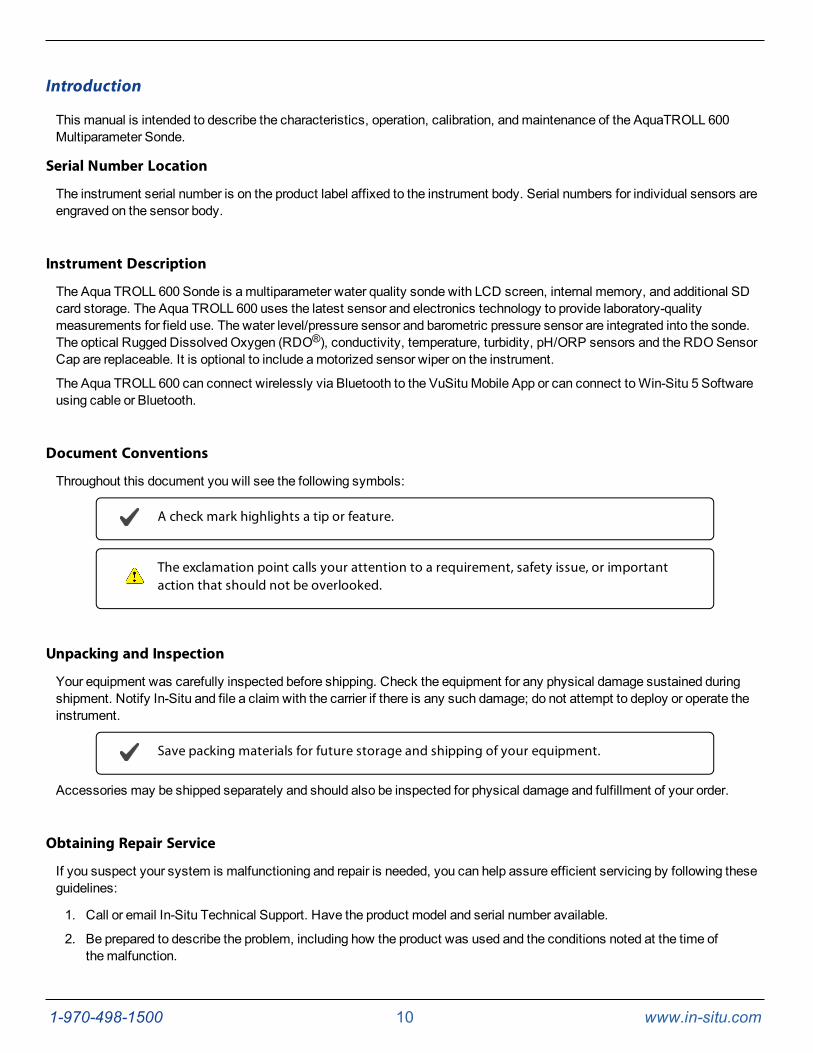
Introduction
This manual is intended to describe the characteristics, operation, calibration, andmaintenance of the AquaTROLL 600Multiparameter Sonde.
Serial Number Location
The instrument serial number is on the product label affixed to the instrument body. Serial numbers for individual sensors areengraved on the sensor body.
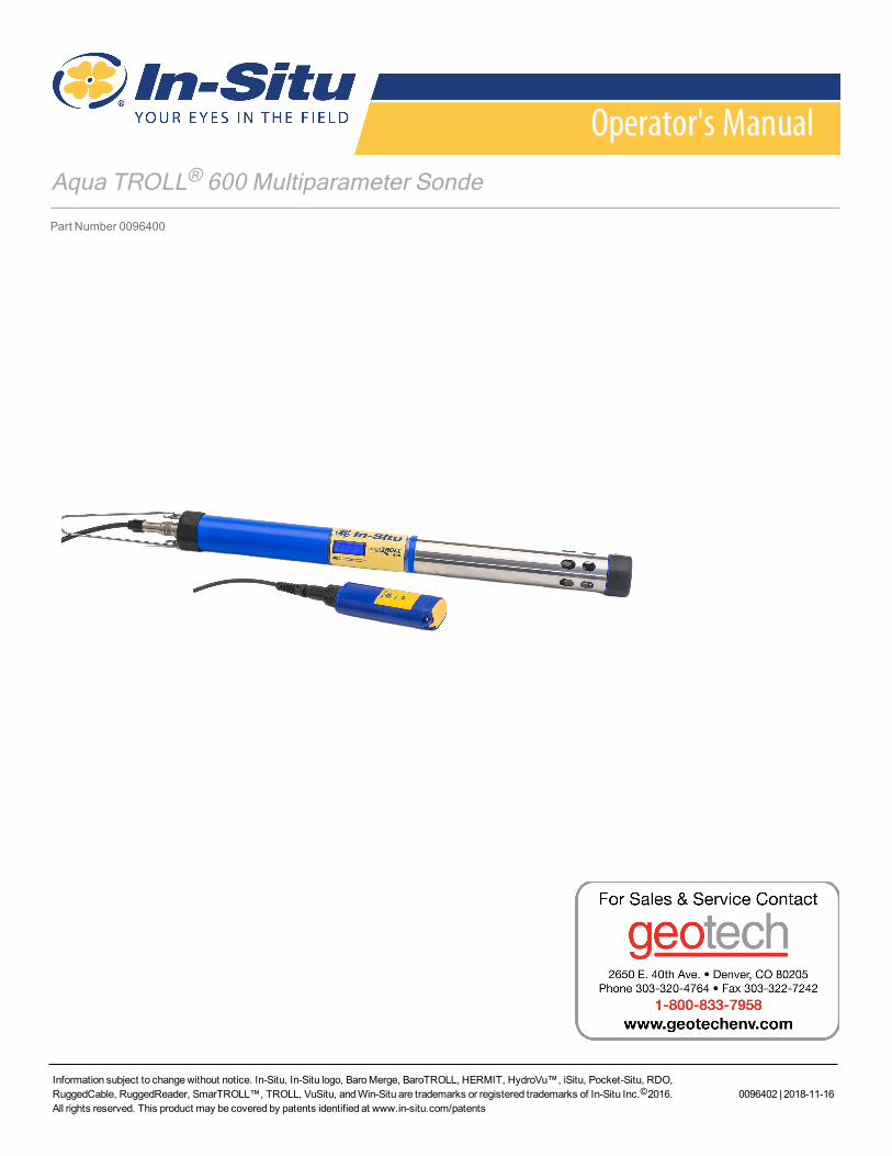
Instrument Description
The Aqua TROLL 600 Sonde is amultiparameter water quality sonde with LCD screen, internal memory, and additional SDcard storage. The Aqua TROLL 600 uses the latest sensor and electronics technology to provide laboratory-qualitymeasurements for field use. The water level/pressure sensor and barometric pressure sensor are integrated into the sonde.The optical Rugged DissolvedOxygen (RDO®), conductivity, temperature, turbidity, pH/ORP sensors and the RDOSensorCap are replaceable. It is optional to include amotorized sensor wiper on the instrument.
The Aqua TROLL 600 can connect wirelessly via Bluetooth to the VuSitu Mobile App or can connect toWin-Situ 5 Softwareusing cable or Bluetooth.
Document Conventions
Throughout this document you will see the following symbols:
A check mark highlights a tip or feature.
The exclamation point calls your attention to a requirement, safety issue, or importantaction that should not be overlooked.
Unpacking and Inspection
Your equipment was carefully inspected before shipping. Check the equipment for any physical damage sustained duringshipment. Notify In-Situ and file a claim with the carrier if there is any such damage; do not attempt to deploy or operate theinstrument.
Save packing materials for future storage and shipping of your equipment.
Accessories may be shipped separately and should also be inspected for physical damage and fulfillment of your order.
Obtaining Repair Service
If you suspect your system is malfunctioning and repair is needed, you can help assure efficient servicing by following theseguidelines:
1. Call or email In-Situ Technical Support. Have the product model and serial number available.
2. Be prepared to describe the problem, including how the product was used and the conditions noted at the time ofthemalfunction.
1-970-498-1500 11 www.in-situ.com
3. If Technical Support determines that service is needed, they will ask your company to fill out the RMA form andpre-approve a specifiedmonetary amount for repair charges. When the form and pre-approval is received,Technical Support will assign an RMA (ReturnMaterial Authorization) number.
4. Clean the product as described in themanual.
5. If the product contains a removable battery, remove and retain it unless you are returning the system for a refund orTechnical Support states otherwise.
6. Carefully pack your product in its original shipping box, if possible.
7. Mark the RMA number clearly on the outside of the box.
8. Send the package, shipping prepaid, to:
In-SituATTN: Repairs221 East Lincoln AvenueFort Collins, CO 80524
The warranty does not cover damage during transit. In-Situ recommends insurance for all shipments. Warranty repairs will beshipped back prepaid.
Outside the U.S.
Contact your international In-Situ distributor for repair and service information.
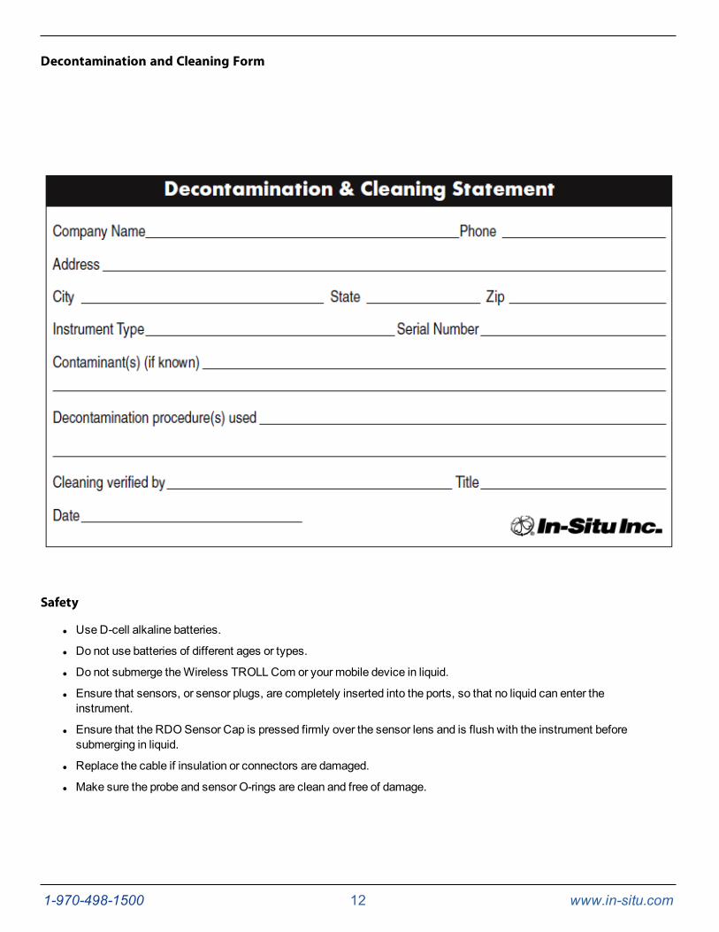
Guidelines for Cleaning Returned Equipment
Please help us protect the health and safety of our employees by cleaning and decontaminating equipment that has beensubjected to potential biological or health hazards, and labeling such equipment. Unfortunately, we cannot service yourequipment without such notification. Please complete and sign the form on page 12 (or a similar statement certifying that theequipment has been cleaned and decontaminated) and send it to us with each instrument.
l We recommend the glassware cleaning product, Alconox, available from In-Situ and from laboratory supplycompanies.
l Clean all cables and remove all foreignmatter.
l Clean the cable connectors with a clean, dry cloth. Do not submerge the connectors.
l Clean the instrument including the nosecone, cable head, and protective caps.
If an instrument is returned to our Service Center for repair or recalibration without astatement that it has been cleaned and decontaminated, or if it is the opinion of ourService Representatives that the equipment presents a potential health or biologicalhazard, we reserve the right to withhold service until proper certification is obtained.
1-970-498-1500 12 www.in-situ.com
Decontamination and Cleaning Form
Safety
l UseD-cell alkaline batteries.
l Do not use batteries of different ages or types.
l Do not submerge theWireless TROLL Com or your mobile device in liquid.
l Ensure that sensors, or sensor plugs, are completely inserted into the ports, so that no liquid can enter theinstrument.
l Ensure that the RDOSensor Cap is pressed firmly over the sensor lens and is flush with the instrument beforesubmerging in liquid.
l Replace the cable if insulation or connectors are damaged.
l Make sure the probe and sensor O-rings are clean and free of damage.
1-970-498-1500 13 www.in-situ.com
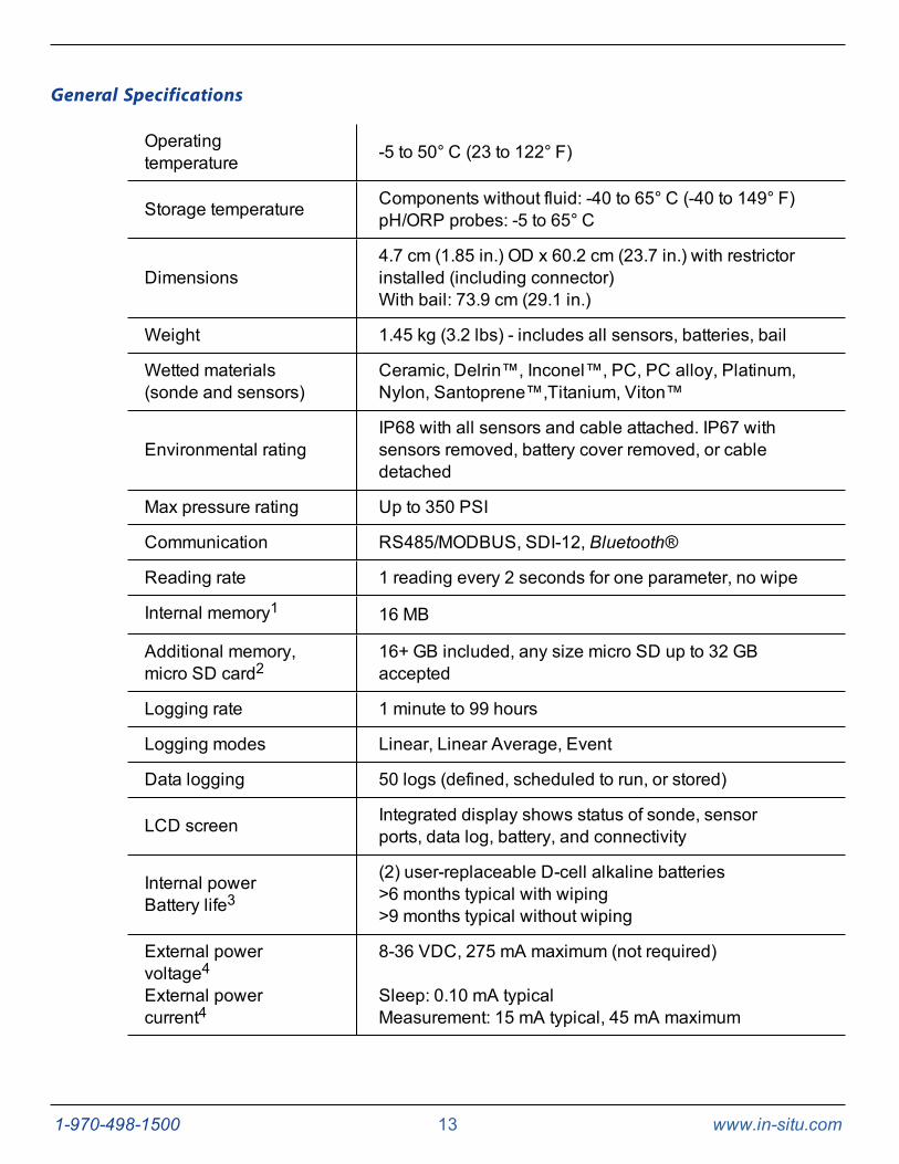
General Specifications
Operatingtemperature -5 to 50° C (23 to 122° F)
Storage temperature Components without fluid: -40 to 65° C (-40 to 149° F)pH/ORP probes: -5 to 65° C
Dimensions4.7 cm (1.85 in.) OD x 60.2 cm (23.7 in.) with restrictorinstalled (including connector)With bail: 73.9 cm (29.1 in.)
Weight 1.45 kg (3.2 lbs) - includes all sensors, batteries, bail
Wetted materials(sonde and sensors)
Ceramic, Delrin™, Inconel™, PC, PC alloy, Platinum,Nylon, Santoprene™,Titanium, Viton™
Environmental ratingIP68 with all sensors and cable attached. IP67 withsensors removed, battery cover removed, or cabledetached
Max pressure rating Up to 350 PSI
Communication RS485/MODBUS, SDI-12, Bluetooth®
Reading rate 1 reading every 2 seconds for one parameter, no wipe
Internal memory1 16 MB
Additional memory,micro SD card2
16+ GB included, any size micro SD up to 32 GBaccepted
Logging rate 1 minute to 99 hours
Logging modes Linear, Linear Average, Event
Data logging 50 logs (defined, scheduled to run, or stored)
LCD screen Integrated display shows status of sonde, sensorports, data log, battery, and connectivity
Internal powerBattery life3
(2) user-replaceable D-cell alkaline batteries>6 months typical with wiping>9 months typical without wiping
External powervoltage4External powercurrent4
8-36 VDC, 275 mA maximum (not required)
Sleep: 0.10 mA typicalMeasurement: 15 mA typical, 45 mA maximum
1-970-498-1500 14 www.in-situ.com
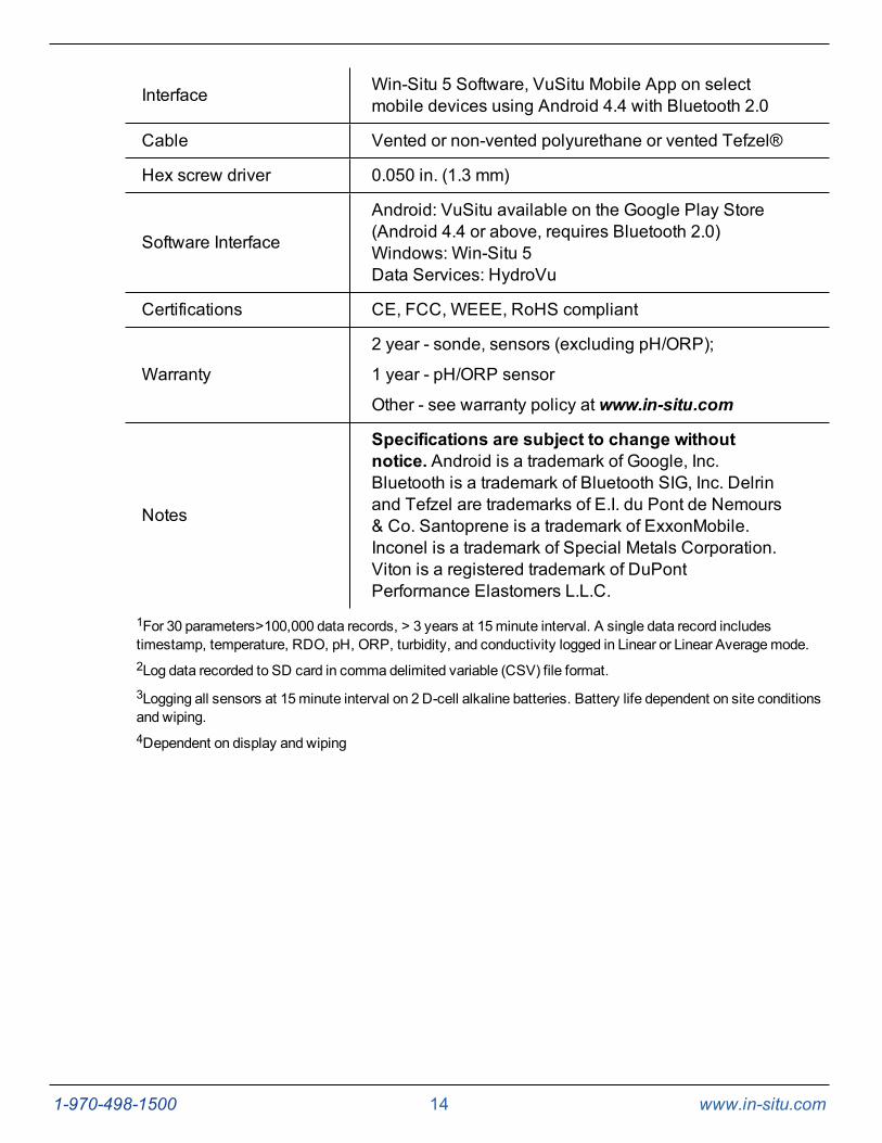
Interface Win-Situ 5 Software, VuSitu Mobile App on selectmobile devices using Android 4.4 with Bluetooth 2.0
Cable Vented or non-vented polyurethane or vented Tefzel®
Hex screw driver 0.050 in. (1.3 mm)
Software Interface
Android: VuSitu available on the Google Play Store(Android 4.4 or above, requires Bluetooth 2.0)Windows: Win-Situ 5Data Services: HydroVu
Certifications CE, FCC, WEEE, RoHS compliant
Warranty
2 year - sonde, sensors (excluding pH/ORP);
1 year - pH/ORP sensor
Other - see warranty policy atwww.in-situ.com
Notes
Specifications are subject to change withoutnotice. Android is a trademark of Google, Inc.Bluetooth is a trademark of Bluetooth SIG, Inc. Delrinand Tefzel are trademarks of E.I. du Pont de Nemours& Co. Santoprene is a trademark of ExxonMobile.Inconel is a trademark of Special Metals Corporation.Viton is a registered trademark of DuPontPerformance Elastomers L.L.C.
1For 30 parameters>100,000 data records, > 3 years at 15minute interval. A single data record includestimestamp, temperature, RDO, pH, ORP, turbidity, and conductivity logged in Linear or Linear Averagemode.2Log data recorded to SD card in comma delimited variable (CSV) file format.3Logging all sensors at 15minute interval on 2 D-cell alkaline batteries. Battery life dependent on site conditionsand wiping.4Dependent on display and wiping

1-970-498-1500 15 www.in-situ.com
Instrument Dimensions with Restrictor On
Total length with connector 60.2 cm (23.7 in.)
Diameter 47 mm (1.85 in.)
Instrument Dimensions with Restrictor Off
Total length with wiper brush on 56.2 cm (22.12 in.)
Total length with wiper brush off 52.6 cm (20.7 in.)
Diameter 41.66 mm (1.64 in.)
Sensor Specifications
Sensor Summary
Sensors ShelfLife*
FieldLife**
RecommendedCalibrationFrequency**
PressureRating -PSI
UsableDepth
Meters Feet
OperationalTemperature
Range
pH/ORP 15months
1 year orgreater 10 to 12 weeks 350 200 650 - 5 to 50° C
RDO NA 2 years orgreater 12months 350 200 650 - 5 to 50° C
Conductivity NA 2 years orgreater
User calibrationonly if needed 350 200 650 - 5 to 50° C
Temperature NA 2 years orgreater NA 350 200 650 - 5 to 50° C
1-970-498-1500 16 www.in-situ.com
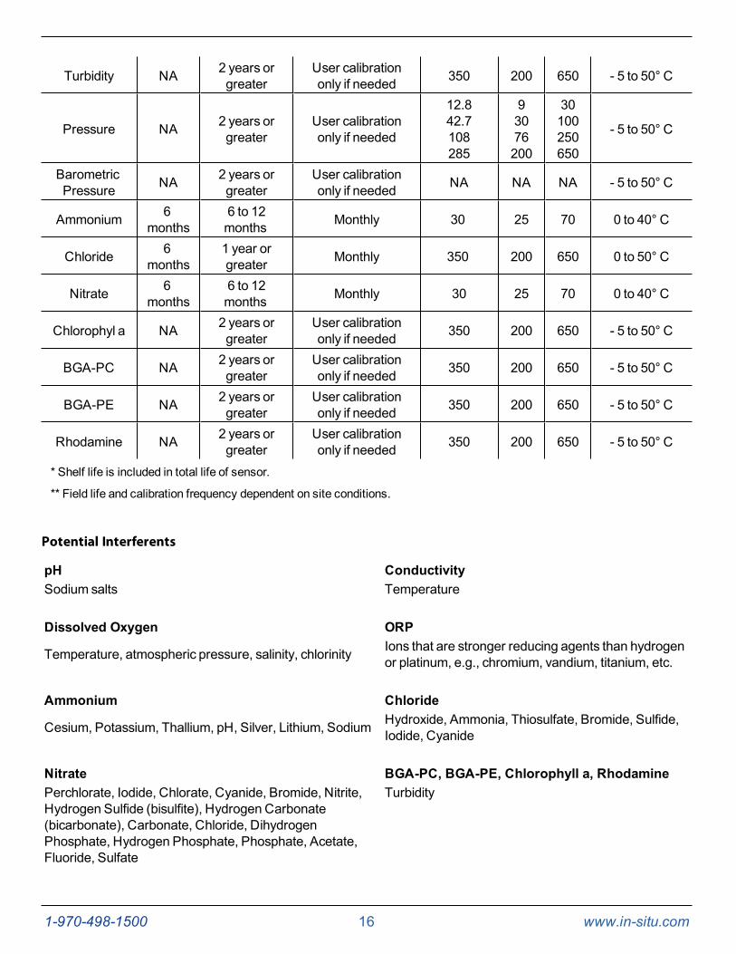
Turbidity NA 2 years orgreater
User calibrationonly if needed 350 200 650 - 5 to 50° C
Pressure NA 2 years orgreater
User calibrationonly if needed
12.842.7108285
93076200
30100250650
- 5 to 50° C
BarometricPressure NA 2 years or
greaterUser calibrationonly if needed NA NA NA - 5 to 50° C
Ammonium 6months
6 to 12months Monthly 30 25 70 0 to 40° C
Chloride 6months
1 year orgreater Monthly 350 200 650 0 to 50° C
Nitrate 6months
6 to 12months Monthly 30 25 70 0 to 40° C
Chlorophyl a NA 2 years orgreater
User calibrationonly if needed 350 200 650 - 5 to 50° C
BGA-PC NA 2 years orgreater
User calibrationonly if needed 350 200 650 - 5 to 50° C
BGA-PE NA 2 years orgreater
User calibrationonly if needed 350 200 650 - 5 to 50° C
Rhodamine NA 2 years orgreater
User calibrationonly if needed 350 200 650 - 5 to 50° C
* Shelf life is included in total life of sensor.
** Field life and calibration frequency dependent on site conditions.
Potential Interferents
pH ConductivitySodium salts Temperature
Dissolved Oxygen ORP
Temperature, atmospheric pressure, salinity, chlorinity Ions that are stronger reducing agents than hydrogenor platinum, e.g., chromium, vandium, titanium, etc.
Ammonium Chloride
Cesium, Potassium, Thallium, pH, Silver, Lithium, Sodium Hydroxide, Ammonia, Thiosulfate, Bromide, Sulfide,Iodide, Cyanide
Nitrate BGA-PC, BGA-PE, Chlorophyll a, RhodaminePerchlorate, Iodide, Chlorate, Cyanide, Bromide, Nitrite,Hydrogen Sulfide (bisulfite), Hydrogen Carbonate(bicarbonate), Carbonate, Chloride, DihydrogenPhosphate, Hydrogen Phosphate, Phosphate, Acetate,Fluoride, Sulfate
Turbidity

1-970-498-1500 17 www.in-situ.com
RDO Cap Chemical Incompatibility
The following chemicals will damage the RDO sensing element.
l Alcohols > 5%
l Hydrogen peroxide > 3%
l Sodium hypochlorite (commercial bleach) > 3%
l Gaseous sulfur dioxide
l Gaseous chlorine
l Do not use in organic solvents (e.g., acetone, chloroform, methylene chloride, etc.), whichmay destroy thesensing element
Ammonium, Chloride and Nitrate Interferent Concentrations
Ammonium
The table below lists concentrations of possible interfering ions that cause 10% error at various levels (in ppm) of NH4+.
Ion 100 ppm NH4+ 10 ppm NH4+ 1 ppm NH4+Celsium (Cs+) 100 10 1
Potassium (K+) 270 27 2.7
Thallium (TI+) 3100 310 31
pH (H+) pH 1.6 pH 2.6 pH 3.6
Silver (Ag+) 270,000 27,000 2,700
Lithium (Li+) 35,000 3,500 350
Sodium (Na+) 11,100 1,100 110
Chloride
The table below lists concentrations of possible interfering ions that cause 10% error at various levels (in ppm) of Cl-.
Ion 100 ppm Cl- 10 ppm Cl- 1 ppm Cl-Hydroxide (OH-) 3,840 384 38.4
Ammonia (NH3) 6 0.6 0.06
Thiosulfate (S2O3 2-) 3 0.3 0.03
Bromide (Br-) 0.68 0.068 6.8 x 10⁻³
Sulfide (S2-) 9 x 10⁻⁵ 9 x 10⁻⁶ 9 x 10⁻⁷
Iodide (I-) 1.8 x 10⁻⁴ 1.8 x 10⁻⁵ 1.8 x 10⁻⁶
Cyanide (CN-) 1.5 x 10⁻⁵ 1.5 x 10⁻⁶ 1.5 x 10⁻⁷
Nitrate
The table below lists concentrations of possible interfering ions that cause 10% error at various levels (in ppm) of N03-.
Ion 100 ppm NO3- as N 10 ppm NO3- as N 1 ppm NO3- as NPerchlorate (CIO4-) 7 x 10⁻² 7 x 10⁻³ 7 x 10⁻⁴
Iodide (I-) 4 0.4 0.04
Chlorate (CIO3-) 30 3 0.3
Cyanide (CN-) 20 2 0.2
1-970-498-1500 18 www.in-situ.com
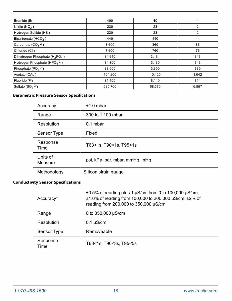
Bromide (Br-) 400 40 4
Nitrite (NO2-) 230 23 2
Hydrogen Sulfide (HS-) 230 23 2
Bicarbonate (HCO3-) 440 440 44
Carbonate (CO3 2-) 8,600 860 86
Chloride (Cl-) 7,600 760 76
Dihydrogen Phosphate (H2PO4-) 34,640 3,464 346
Hydrogen Phosphate (HPO4 2-) 34,300 3,430 343
Phosphate (PO4 3-) 33,900 3,390 339
Acetate (OAc-) 104,200 10,420 1,042
Fluoride (F-) 81,400 8,140 814
Sulfate (SO4 2-) 685,700 68,570 6,857
Barometric Pressure Sensor Specifications
Accuracy ±1.0 mbar
Range 300 to 1,100 mbar
Resolution 0.1 mbar
Sensor Type Fixed
ResponseTime T63<1s, T90<1s, T95<1s
Units ofMeasure psi, kPa, bar, mbar, mmHg, inHg
Methodology Silicon strain gauge
Conductivity Sensor Specifications
Accuracy*±0.5% of reading plus 1 μS/cm from 0 to 100,000 μS/cm;±1.0% of reading from 100,000 to 200,000 μS/cm; ±2% ofreading from 200,000 to 350,000 µS/cm
Range 0 to 350,000 μS/cm
Resolution 0.1 µS/cm
Sensor Type Removeable
ResponseTime T63<1s, T90<3s, T95<5s
1-970-498-1500 19 www.in-situ.com
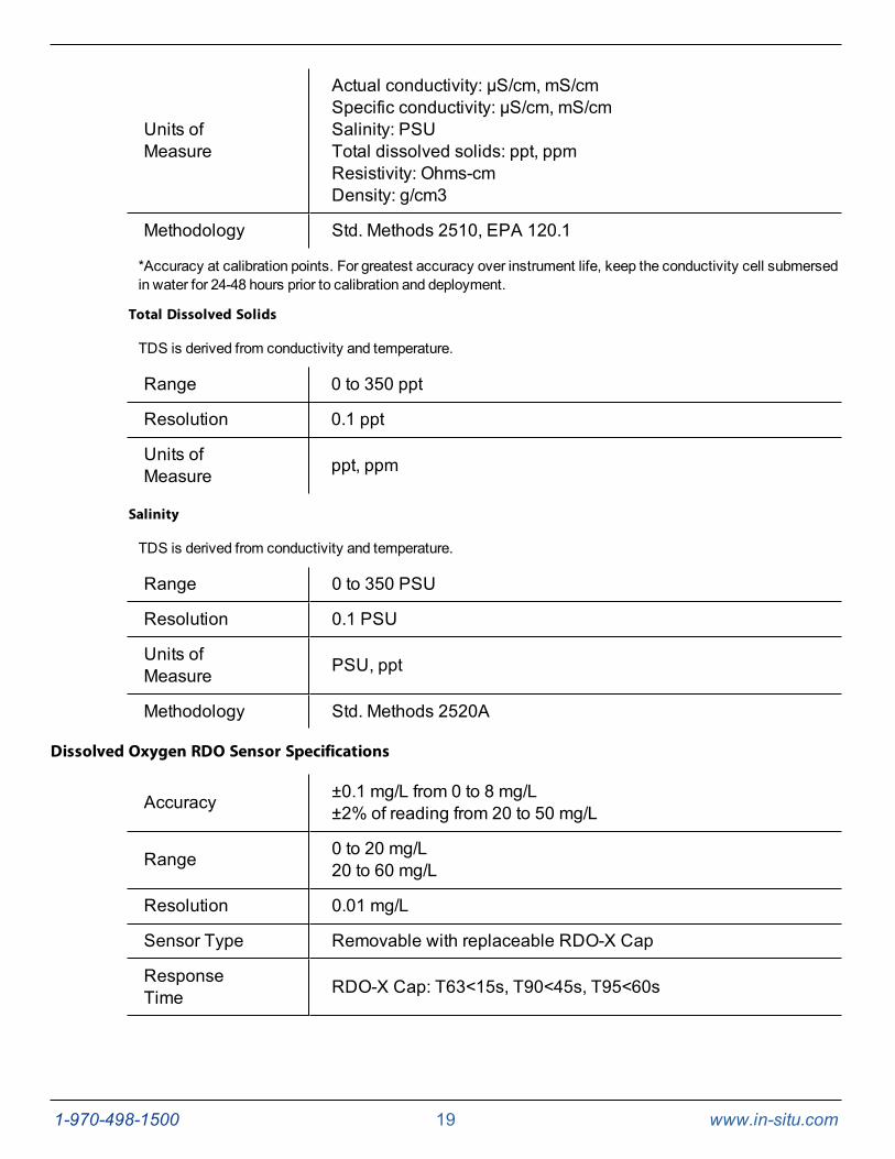
Units ofMeasure
Actual conductivity: μS/cm, mS/cmSpecific conductivity: μS/cm, mS/cmSalinity: PSUTotal dissolved solids: ppt, ppmResistivity: Ohms-cmDensity: g/cm3
Methodology Std. Methods 2510, EPA 120.1
*Accuracy at calibration points. For greatest accuracy over instrument life, keep the conductivity cell submersedin water for 24-48 hours prior to calibration and deployment.
Total Dissolved Solids
TDS is derived from conductivity and temperature.
Range 0 to 350 ppt
Resolution 0.1 ppt
Units ofMeasure ppt, ppm
Salinity
TDS is derived from conductivity and temperature.
Range 0 to 350 PSU
Resolution 0.1 PSU
Units ofMeasure PSU, ppt
Methodology Std. Methods 2520A
Dissolved Oxygen RDO Sensor Specifications
Accuracy ±0.1 mg/L from 0 to 8 mg/L±2% of reading from 20 to 50 mg/L
Range 0 to 20 mg/L20 to 60 mg/L
Resolution 0.01 mg/L
Sensor Type Removable with replaceable RDO-X Cap
ResponseTime RDO-X Cap: T63<15s, T90<45s, T95<60s
1-970-498-1500 20 www.in-situ.com
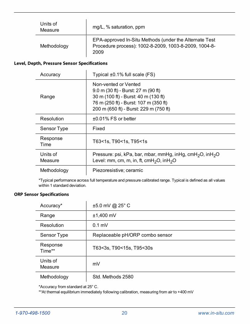
Units ofMeasure mg/L, % saturation, ppm
MethodologyEPA-approved In-Situ Methods (under the Alternate TestProcedure process): 1002-8-2009, 1003-8-2009, 1004-8-2009
Level, Depth, Pressure Sensor Specifications
Accuracy Typical ±0.1% full scale (FS)
Range
Non-vented or Vented9.0 m (30 ft) - Burst: 27 m (90 ft)30 m (100 ft) - Burst: 40 m (130 ft)76 m (250 ft) - Burst: 107 m (350 ft)200 m (650 ft) - Burst: 229 m (750 ft)
Resolution ±0.01% FS or better
Sensor Type Fixed
ResponseTime T63<1s, T90<1s, T95<1s
Units ofMeasure
Pressure: psi, kPa, bar, mbar, mmHg, inHg, cmH2O, inH2OLevel: mm, cm, m, in, ft, cmH2O, inH2O
Methodology Piezoresistive; ceramic
*Typical performance across full temperature and pressure calibrated range. Typical is defined as all valueswithin 1 standard deviation.
ORP Sensor Specifications
Accuracy* ±5.0 mV @ 25° C
Range ±1,400 mV
Resolution 0.1 mV
Sensor Type Replaceable pH/ORP combo sensor
ResponseTime** T63<3s, T90<15s, T95<30s
Units ofMeasure mV
Methodology Std. Methods 2580
*Accuracy from standard at 25° C.**At thermal equilibrium immediately following calibration, measuring from air to +400mV
1-970-498-1500 21 www.in-situ.com
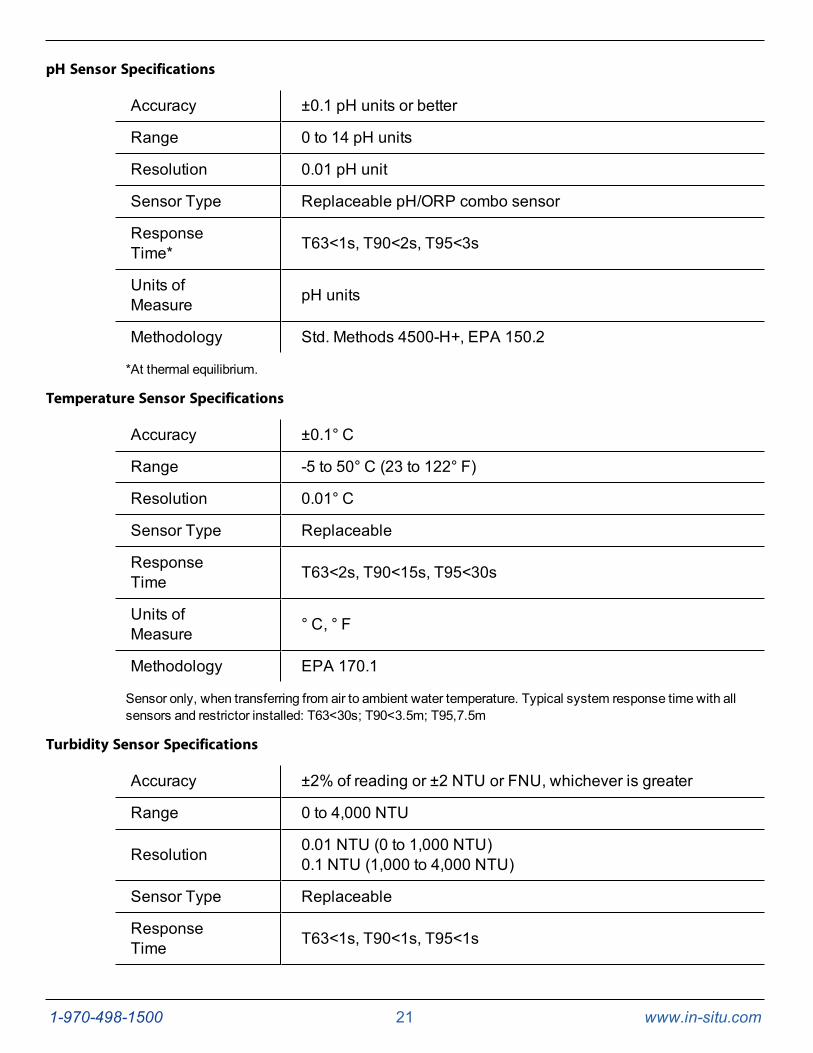
pH Sensor Specifications
Accuracy ±0.1 pH units or better
Range 0 to 14 pH units
Resolution 0.01 pH unit
Sensor Type Replaceable pH/ORP combo sensor
ResponseTime* T63<1s, T90<2s, T95<3s
Units ofMeasure pH units
Methodology Std. Methods 4500-H+, EPA 150.2
*At thermal equilibrium.
Temperature Sensor Specifications
Accuracy ±0.1° C
Range -5 to 50° C (23 to 122° F)
Resolution 0.01° C
Sensor Type Replaceable
ResponseTime T63<2s, T90<15s, T95<30s
Units ofMeasure ° C, ° F
Methodology EPA 170.1
Sensor only, when transferring from air to ambient water temperature. Typical system response time with allsensors and restrictor installed: T63<30s; T90<3.5m; T95,7.5m
Turbidity Sensor Specifications
Accuracy ±2% of reading or ±2 NTU or FNU, whichever is greater
Range 0 to 4,000 NTU
Resolution 0.01 NTU (0 to 1,000 NTU)0.1 NTU (1,000 to 4,000 NTU)
Sensor Type Replaceable
ResponseTime T63<1s, T90<1s, T95<1s
1-970-498-1500 22 www.in-situ.com
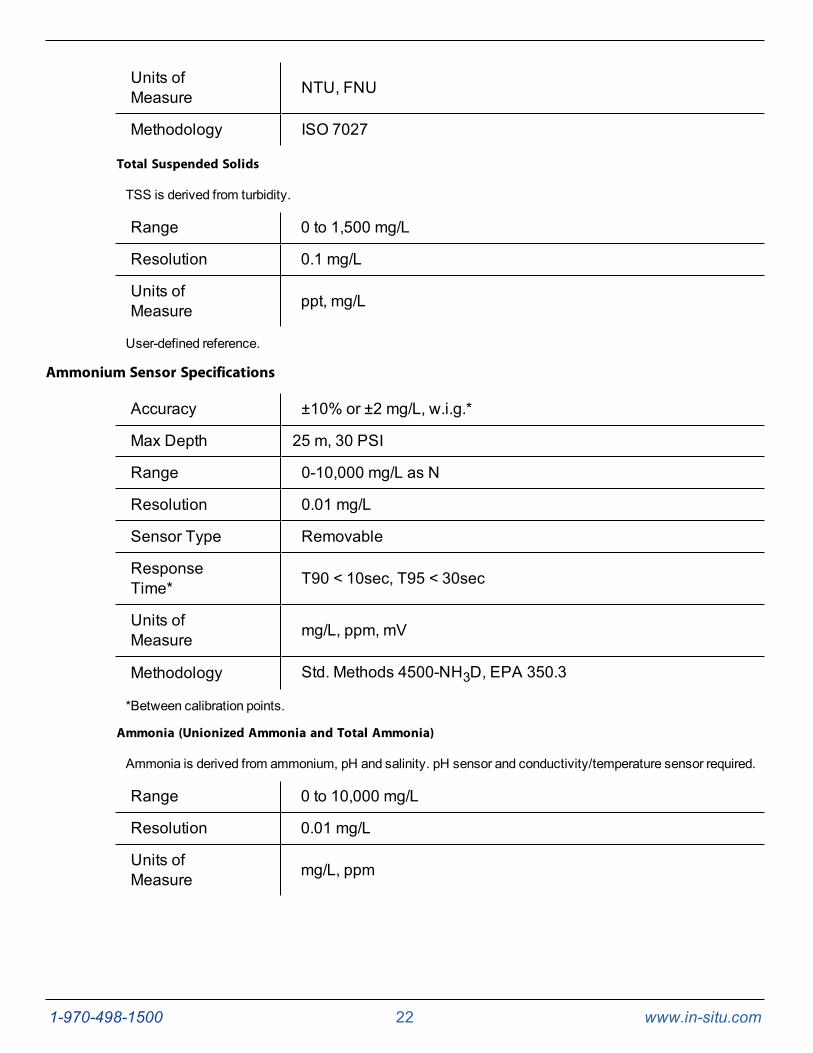
Units ofMeasure NTU, FNU
Methodology ISO 7027
Total Suspended Solids
TSS is derived from turbidity.
Range 0 to 1,500 mg/L
Resolution 0.1 mg/L
Units ofMeasure ppt, mg/L
User-defined reference.
Ammonium Sensor Specifications
Accuracy ±10% or ±2 mg/L, w.i.g.*
Max Depth 25 m, 30 PSI
Range 0-10,000 mg/L as N
Resolution 0.01 mg/L
Sensor Type Removable
ResponseTime* T90 < 10sec, T95 < 30sec
Units ofMeasure mg/L, ppm, mV
Methodology Std. Methods 4500-NH3D, EPA 350.3
*Between calibration points.
Ammonia (Unionized Ammonia and Total Ammonia)
Ammonia is derived from ammonium, pH and salinity. pH sensor and conductivity/temperature sensor required.
Range 0 to 10,000 mg/L
Resolution 0.01 mg/L
Units ofMeasure mg/L, ppm
1-970-498-1500 23 www.in-situ.com
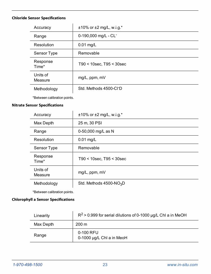
Chloride Sensor Specifications
Accuracy ±10% or ±2 mg/L, w.i.g.*
Range 0-190,000 mg/L - CL-
Resolution 0.01 mg/L
Sensor Type Removable
ResponseTime* T90 < 10sec, T95 < 30sec
Units ofMeasure mg/L, ppm, mV
Methodology Std. Methods 4500-Cl-D
*Between calibration points.
Nitrate Sensor Specifications
Accuracy ±10% or ±2 mg/L, w.i.g.*
Max Depth 25 m, 30 PSI
Range 0-50,000 mg/L as N
Resolution 0.01 mg/L
Sensor Type Removable
ResponseTime* T90 < 10sec, T95 < 30sec
Units ofMeasure mg/L, ppm, mV
Methodology Std. Methods 4500-NO3D
*Between calibration points.
Chlorophyll a Sensor Specifications
Linearity R2 > 0.999 for serial dilutions of 0-1000 µg/L Chl a in MeOH
Max Depth 200 m
Range 0-100 RFU0-1000 µg/L Chl a in MeoH
1-970-498-1500 24 www.in-situ.com
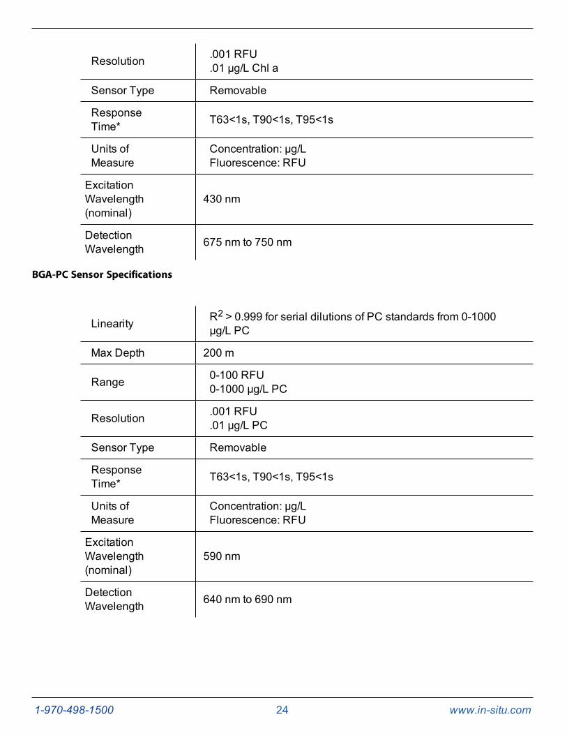
Resolution .001 RFU.01 µg/L Chl a
Sensor Type Removable
ResponseTime* T63<1s, T90<1s, T95<1s
Units ofMeasure
Concentration: µg/LFluorescence: RFU
ExcitationWavelength(nominal)
430 nm
DetectionWavelength 675 nm to 750 nm
BGA-PC Sensor Specifications
Linearity R2 > 0.999 for serial dilutions of PC standards from 0-1000µg/L PC
Max Depth 200 m
Range 0-100 RFU0-1000 µg/L PC
Resolution .001 RFU.01 µg/L PC
Sensor Type Removable
ResponseTime* T63<1s, T90<1s, T95<1s
Units ofMeasure
Concentration: µg/LFluorescence: RFU
ExcitationWavelength(nominal)
590 nm
DetectionWavelength 640 nm to 690 nm
1-970-498-1500 25 www.in-situ.com
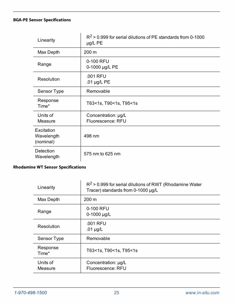
BGA-PE Sensor Specifications
Linearity R2 > 0.999 for serial dilutions of PE standards from 0-1000µg/L PE
Max Depth 200 m
Range 0-100 RFU0-1000 µg/L PE
Resolution .001 RFU.01 µg/L PE
Sensor Type Removable
ResponseTime* T63<1s, T90<1s, T95<1s
Units ofMeasure
Concentration: µg/LFluorescence: RFU
ExcitationWavelength(nominal)
498 nm
DetectionWavelength 575 nm to 625 nm
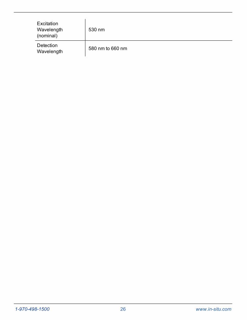
Rhodamine WT Sensor Specifications
Linearity R2 > 0.999 for serial dilutions of RWT (Rhodamine WaterTracer) standards from 0-1000 µg/L
Max Depth 200 m
Range 0-100 RFU0-1000 µg/L
Resolution .001 RFU.01 µg/L
Sensor Type Removable
ResponseTime* T63<1s, T90<1s, T95<1s
Units ofMeasure
Concentration: µg/LFluorescence: RFU
1-970-498-1500 26 www.in-situ.com
ExcitationWavelength(nominal)
530 nm
DetectionWavelength 580 nm to 660 nm
1-970-498-1500 27 www.in-situ.com
Instrument Overview
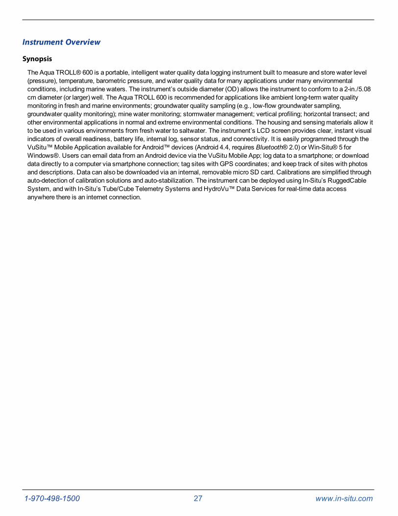
Synopsis
The Aqua TROLL® 600 is a portable, intelligent water quality data logging instrument built to measure and store water level(pressure), temperature, barometric pressure, and water quality data for many applications under many environmentalconditions, includingmarine waters. The instrument’s outside diameter (OD) allows the instrument to conform to a 2-in./5.08cm diameter (or larger) well. The Aqua TROLL 600 is recommended for applications like ambient long-term water qualitymonitoring in fresh andmarine environments; groundwater quality sampling (e.g., low-flow groundwater sampling,groundwater quality monitoring); mine water monitoring; stormwater management; vertical profiling; horizontal transect; andother environmental applications in normal and extreme environmental conditions. The housing and sensingmaterials allow itto be used in various environments from fresh water to saltwater. The instrument’s LCD screen provides clear, instant visualindicators of overall readiness, battery life, internal log, sensor status, and connectivity. It is easily programmed through theVuSitu™Mobile Application available for Android™ devices (Android 4.4, requires Bluetooth® 2.0) orWin-Situ® 5 forWindows®. Users can email data from an Android device via the VuSitu Mobile App; log data to a smartphone; or downloaddata directly to a computer via smartphone connection; tag sites with GPS coordinates; and keep track of sites with photosand descriptions. Data can also be downloaded via an internal, removablemicro SD card. Calibrations are simplified throughauto-detection of calibration solutions and auto-stabilization. The instrument can be deployed using In-Situ’s RuggedCableSystem, and with In-Situ’s Tube/Cube Telemetry Systems and HydroVu™Data Services for real-time data accessanywhere there is an internet connection.
1-970-498-1500 28 www.in-situ.com
System Components
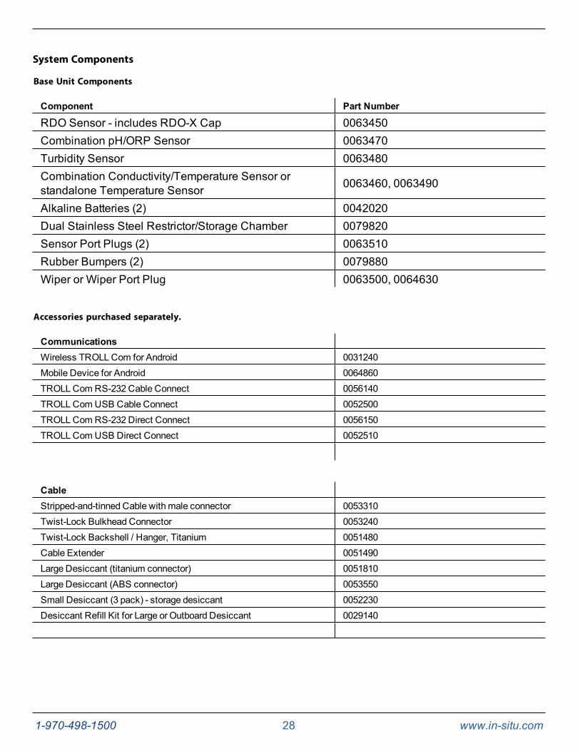
Base Unit Components
Component Part Number
RDO Sensor - includes RDO-X Cap 0063450Combination pH/ORP Sensor 0063470Turbidity Sensor 0063480Combination Conductivity/Temperature Sensor orstandalone Temperature Sensor 0063460, 0063490
Alkaline Batteries (2) 0042020Dual Stainless Steel Restrictor/Storage Chamber 0079820Sensor Port Plugs (2) 0063510Rubber Bumpers (2) 0079880Wiper or Wiper Port Plug 0063500, 0064630
Accessories purchased separately.
CommunicationsWireless TROLLCom for Android 0031240Mobile Device for Android 0064860TROLLCom RS-232 Cable Connect 0056140TROLLCom USB Cable Connect 0052500TROLLCom RS-232 Direct Connect 0056150TROLLCom USB Direct Connect 0052510
CableStripped-and-tinned Cable with male connector 0053310Twist-Lock Bulkhead Connector 0053240Twist-Lock Backshell / Hanger, Titanium 0051480Cable Extender 0051490Large Desiccant (titanium connector) 0051810Large Desiccant (ABS connector) 0053550Small Desiccant (3 pack) - storage desiccant 0052230Desiccant Refill Kit for Large or Outboard Desiccant 0029140
1-970-498-1500 29 www.in-situ.com
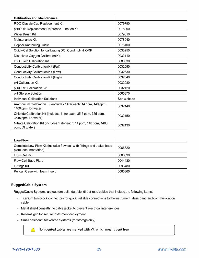
Calibration and MaintenanceRDO Classic Cap Replacement Kit 0079790pH/ORP Replacement Reference Junction Kit 0078990Wiper Brush Kit 0079810Maintenance Kit 0078940Copper Antifouling Guard 0076100Quick-Cal Solution for calibrating DO, Cond., pH & ORP 0033250DissolvedOxygen Calibration Kit 0032110D.O. Field Calibration Kit 0080830Conductivity Calibration Kit (Full) 0032090Conductivity Calibration Kit (Low) 0032630Conductivity Calibration Kit (High) 0032640pH Calibration Kit 0032080pH/ORP Calibration Kit 0032120pH Storage Solution 0065370Individual Calibration Solutions See websiteAmmonium Calibration Kit (includes 1 liter each: 14 ppm, 140 ppm,1400 ppm, DI water) 0032140
Chloride Calibration Kit (includes 1 liter each: 35.5 ppm, 355 ppm,3545 ppm, DI water) 0032150
Nitrate Calibration Kit (includes 1 liter each: 14 ppm, 140 ppm, 1400ppm, DI water) 0032130
Low-FlowComplete Low-Flow Kit (includes flow cell with fittings and stake, baseplate, documentation) 0066820
Flow Cell Kit 0066830Flow Cell Base Plate 0044430Fittings Kit 0093480Pelican Case with foam insert 0066860
RuggedCable System
RuggedCable Systems are custom-built, durable, direct-read cables that include the following items.
l Titanium twist-lock connectors for quick, reliable connections to the instrument, desiccant, and communicationcable
l Metal shield beneath the cable jacket to prevent electrical interferences
l Kellems grip for secure instrument deployment
l Small desiccant for vented systems (for storage only)
Non-vented cables are marked with VF, which means vent free.
1-970-498-1500 30 www.in-situ.com
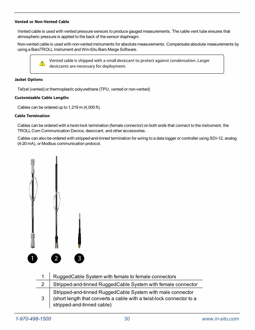
Vented or Non-Vented Cable
Vented cable is used with vented pressure sensors to produce gaugedmeasurements. The cable vent tube ensures thatatmospheric pressure is applied to the back of the sensor diaphragm.
Non-vented cable is used with non-vented instruments for absolute measurements. Compensate absolute measurements byusing a BaroTROLL Instrument andWin-Situ BaroMerge Software.
Vented cable is shipped with a small desiccant to protect against condensation. Largerdesiccants are necessary for deployment.
Jacket Options
Tefzel (vented) or thermoplastic polyurethane (TPU, vented or non-vented)
Customizable Cable Lengths
Cables can be ordered up to 1,219m (4,000 ft).
Cable Termination
Cables can be ordered with a twist-lock termination (female connector) on both ends that connect to the instrument, theTROLLCom Communication Device, desiccant, and other accessories.
Cables can also be ordered with stripped-and-tinned termination for wiring to a data logger or controller using SDI-12, analog(4-20mA), or Modbus communication protocol.
1 RuggedCable System with female to female connectors2 Stripped-and-tinned RuggedCable System with female connector
3Stripped-and-tinned RuggedCable System with male connector(short length that converts a cable with a twist-lock connector to astripped-and-tinned cable)

1-970-498-1500 31 www.in-situ.com
1-970-498-1500 32 www.in-situ.com
Instrument Setup
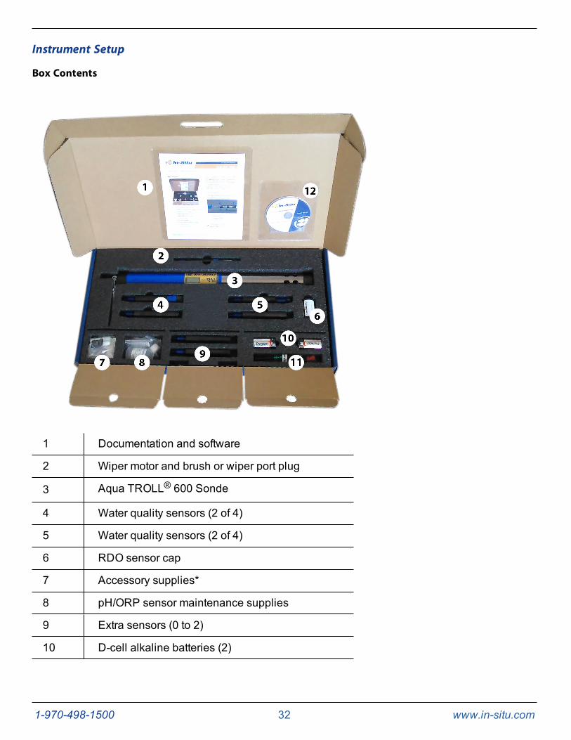
Box Contents
1 Documentation and software
2 Wiper motor and brush or wiper port plug
3 Aqua TROLL® 600 Sonde
4 Water quality sensors (2 of 4)
5 Water quality sensors (2 of 4)
6 RDO sensor cap
7 Accessory supplies*
8 pH/ORP sensor maintenance supplies
9 Extra sensors (0 to 2)
10 D-cell alkaline batteries (2)
1-970-498-1500 33 www.in-situ.com
11 Instrument tools†
12 Software CD
* Accessory supplies include wiper screws (3), wiper brushes (3), wiper brush holders (3), silicone lubricant for O-rings (2),RDO calibration sponges (3), battery compartment desiccant, replacement battery compartment hex screw driver, lens cloth,andmicro SD card adapter.
† Instrument tools include a 0.050 in./1.3 mm hex screwdriver for sensor screws, a flathead screwdriver for the pH referencejunction, and a Phillips head screwdriver for bail screws.
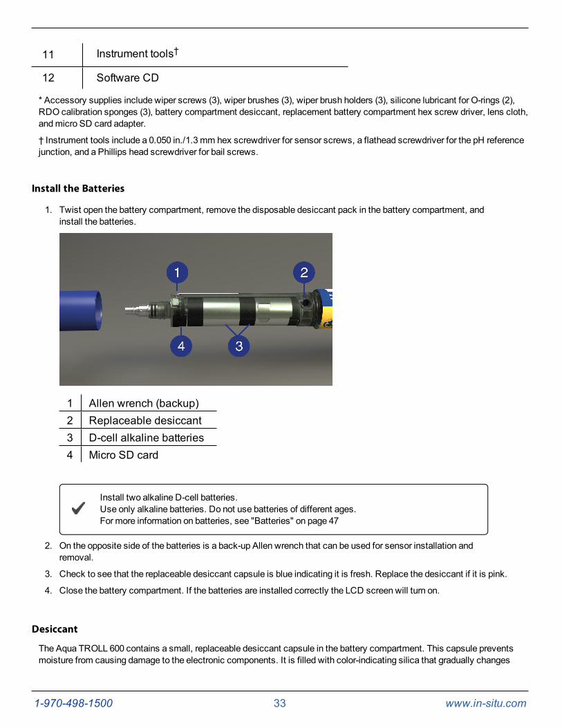
Install the Batteries
1. Twist open the battery compartment, remove the disposable desiccant pack in the battery compartment, andinstall the batteries.
1 Allen wrench (backup)2 Replaceable desiccant3 D-cell alkaline batteries4 Micro SD card
Install two alkaline D-cell batteries.Use only alkaline batteries. Do not use batteries of different ages.For more information on batteries, see "Batteries" on page 47
2. On the opposite side of the batteries is a back-up Allen wrench that can be used for sensor installation andremoval.
3. Check to see that the replaceable desiccant capsule is blue indicating it is fresh. Replace the desiccant if it is pink.
4. Close the battery compartment. If the batteries are installed correctly the LCD screen will turn on.
Desiccant
The Aqua TROLL 600 contains a small, replaceable desiccant capsule in the battery compartment. This capsule preventsmoisture from causing damage to the electronic components. It is filled with color-indicating silica that gradually changes
1-970-498-1500 34 www.in-situ.com
from purple to pink as the desiccant's effectiveness decreases. Replace the desiccant when the desiccant has turned pink.The desiccant is included in the Aqua TROLL 600Maintenance Kit (0078940).
Replace the Desiccant
1. Remove the battery cover.
2. Remove the backup wrench tool from the back of the battery compartment.
3. Insert the backup wrench into the small hole on the back side of the battery compartment and push the desiccantcapsule out.
4. Insert a new desiccant capsule and push the capsule in fully using the wrench.
Install the Wiper Motor and Sensors
1. Remove the restrictor.
2. Remove the protective sticker from the end of the sonde to expose the sensor ports.
Rubber bumpers are included on the ends of the sonde to help prevent the sonde from rolling offworking surfaces. You can deploy the sonde with or without these safeguards.
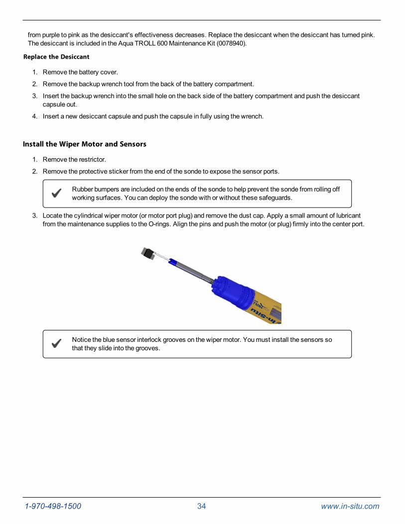
3. Locate the cylindrical wiper motor (or motor port plug) and remove the dust cap. Apply a small amount of lubricantfrom themaintenance supplies to the O-rings. Align the pins and push themotor (or plug) firmly into the center port.
Notice the blue sensor interlock grooves on the wiper motor. Youmust install the sensors sothat they slide into the grooves.
1-970-498-1500 35 www.in-situ.com
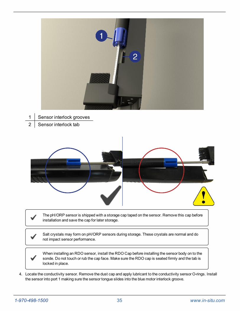
1 Sensor interlock grooves2 Sensor interlock tab
The pH/ORP sensor is shipped with a storage cap taped on the sensor. Remove this cap beforeinstallation and save the cap for later storage.
Salt crystals may form on pH/ORP sensors during storage. These crystals are normal and donot impact sensor performance.
When installing an RDO sensor, install the RDOCap before installing the sensor body on to thesonde. Do not touch or rub the cap face. Make sure the RDO cap is seated firmly and the tab islocked in place.
4. Locate the conductivity sensor. Remove the dust cap and apply lubricant to the conductivity sensor O-rings. Installthe sensor into port 1 making sure the sensor tongue slides into the bluemotor interlock groove.
1-970-498-1500 36 www.in-situ.com
Sensors can be installed in any port, however, installing the conductivity sensor in port 1 allowsfor themost efficient energy consumption.
5. Install the remaining sensors, applying lube to all O-rings. Sensors should be seated tightly together with no gapsbetween connecting edges or the instrument base.
6. When all sensors are installed, use the Allen wrench to tighten the screw at the base of each sensor. Do notovertighten the screws.
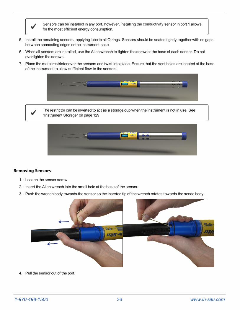
7. Place themetal restrictor over the sensors and twist into place. Ensure that the vent holes are located at the baseof the instrument to allow sufficient flow to the sensors.
The restrictor can be inverted to act as a storage cup when the instrument is not in use. See"Instrument Storage" on page 129
Removing Sensors
1. Loosen the sensor screw.
2. Insert the Allen wrench into the small hole at the base of the sensor.
3. Push the wrench body towards the sensor so the inserted tip of the wrench rotates towards the sonde body.
4. Pull the sensor out of the port.
1-970-498-1500 37 www.in-situ.com
Connecting to the Sonde
Connecting RuggedCable
Connect the Instrument to the RuggedCable
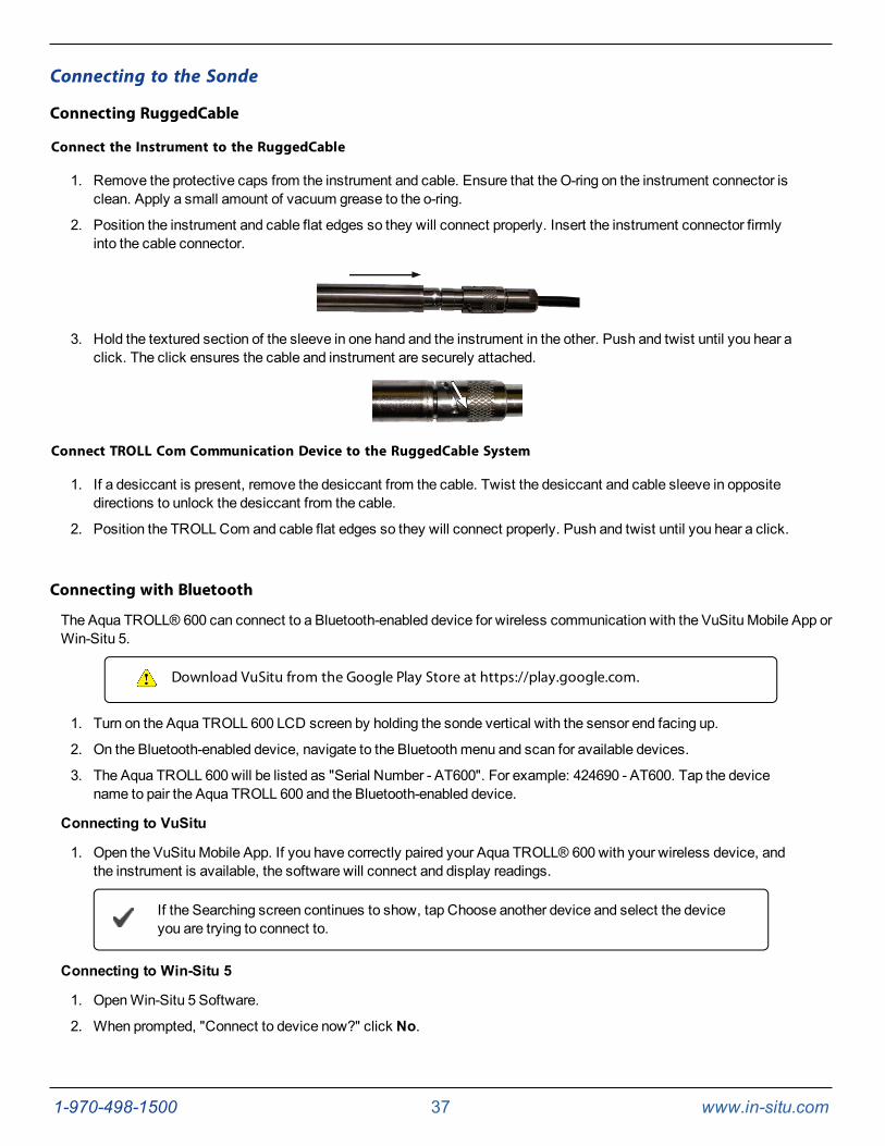
1. Remove the protective caps from the instrument and cable. Ensure that the O-ring on the instrument connector isclean. Apply a small amount of vacuum grease to the o-ring.
2. Position the instrument and cable flat edges so they will connect properly. Insert the instrument connector firmlyinto the cable connector.
3. Hold the textured section of the sleeve in one hand and the instrument in the other. Push and twist until you hear aclick. The click ensures the cable and instrument are securely attached.
Connect TROLL Com Communication Device to the RuggedCable System
1. If a desiccant is present, remove the desiccant from the cable. Twist the desiccant and cable sleeve in oppositedirections to unlock the desiccant from the cable.
2. Position the TROLLCom and cable flat edges so they will connect properly. Push and twist until you hear a click.
Connecting with Bluetooth
The Aqua TROLL® 600 can connect to a Bluetooth-enabled device for wireless communication with the VuSitu Mobile App orWin-Situ 5.
Download VuSitu from the Google Play Store at https://play.google.com.
1. Turn on the Aqua TROLL 600 LCD screen by holding the sonde vertical with the sensor end facing up.
2. On the Bluetooth-enabled device, navigate to the Bluetoothmenu and scan for available devices.
3. The Aqua TROLL 600 will be listed as "Serial Number - AT600". For example: 424690 - AT600. Tap the devicename to pair the Aqua TROLL 600 and the Bluetooth-enabled device.
Connecting to VuSitu
1. Open the VuSitu Mobile App. If you have correctly paired your Aqua TROLL® 600 with your wireless device, andthe instrument is available, the software will connect and display readings.
If the Searching screen continues to show, tap Choose another device and select the deviceyou are trying to connect to.
Connecting to Win-Situ 5
1. OpenWin-Situ 5 Software.
2. When prompted, "Connect to device now?" click No.
1-970-498-1500 38 www.in-situ.com
3. Click Preferences, then click Comm Settings.
4. Select the correct Com port used by Bluetooth, then select the following settings:
l Baud: 19200
l Data Bits: 8
l Parity Bits: None
l Stop Bits: 1
l Device Address: 1
l Mode: Modbus-ASCII
5. Click the checkmark, then click the Connect button in the lower right hand corner.
Connecting to a Wireless TROLL Com
AWireless TROLLCom can be used to connect the instrument to software if the sonde is deployed on a cable.
1. Turn on theWireless TROLLCom.
2. Make sure the cable is connected to the instrument as well as the communication device.
3. Go to Bluetooth settings on your mobile device or computer.
4. From the Bluetooth section, search for devices.
5. Tap or click the serial number of the communication device to pair the device with the phone or computer. Theserial number is located under the USB flap.
Connecting to VuSitu
1. Open the VuSitu Mobile App. If you have correctly paired yourWireless TROLLCom with your wireless device,and the instrument is available, the software will connect and display readings.
If the Searching screen continues to show, tap "Choose another device" and select the deviceyou are trying to connect to.
Connecting to Win-Situ 5
1. OpenWin-Situ 5 Software.
2. When prompted, "Connect to device now?" click No.
3. Plug the USB charging cable into the computer andWireless TROLLCom.
4. Click Preferences, then click Comm Settings.
5. Select the correct Com port used by the charging cable, then select the communication settings for the instrumentyou are connecting. The following default communication settings aremost common for In-Situ instruments:
l Baud: 19200
l Data Bits: 8
l Parity Bits: Even
l Stop Bits: 1
l Device Address: 1
l Mode: Modbus-RTU
If you cannot connect using these settings, click the "Search for Devices" or "Reset All Devices" button.
6. Click the checkmark, then click the Connect button in the lower right hand corner.
1-970-498-1500 39 www.in-situ.com
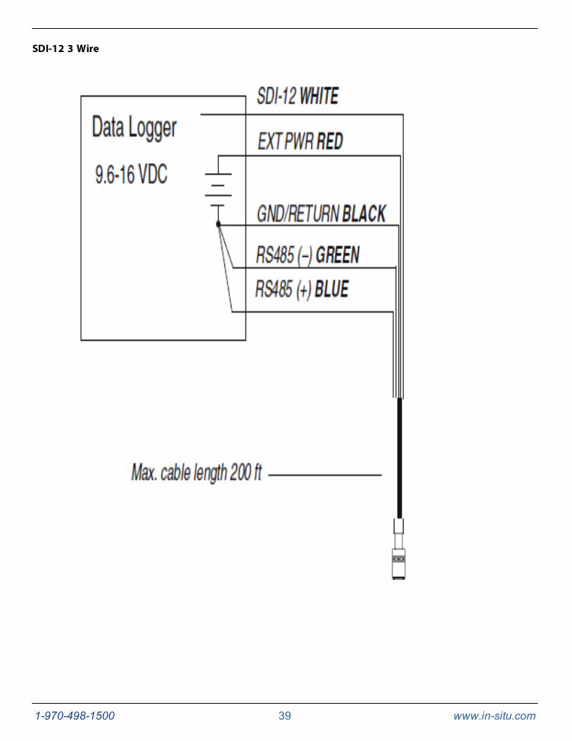
SDI-12 3 Wire
1-970-498-1500 40 www.in-situ.com
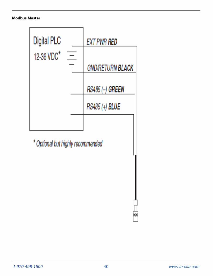
Modbus Master
1-970-498-1500 41 www.in-situ.com
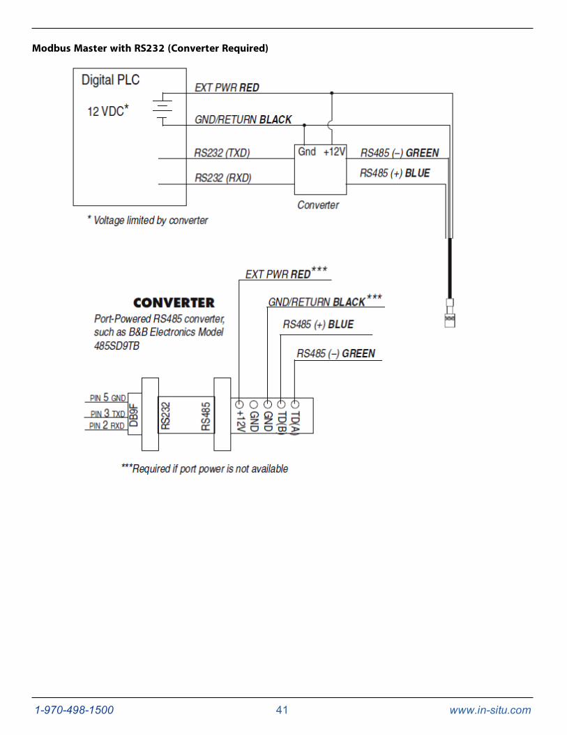
Modbus Master with RS232 (Converter Required)
1-970-498-1500 42 www.in-situ.com
Modbus PLC Interface Overview
TheModbus PLC Interface is a simplifiedmethod of communicating with the Aqua TROLL® 600 using theModbus protocol.It reduces programming complexity and allows the user to remove sensors and reinstall them in different ports. Pleaseobserve the following limitations when using this interface:
1. Only one sensor of any sensor model can be used in the sonde (for example: only one turbidity sensor can beinstalled).
2. If a parameter is provided by more than one of the installed sensors, the interface will return the first valueavailable.
3. Firmware version 1.71 or later must be installed on the sonde.
For information about the full Modbus capabilities of your sonde, see the Aqua TROLL® 600 Interface Specification atwww.in-situ.com/support/type/documentation.
Setting Up the Instrument
1. Install the sensors and turn on the display by holding the instrument vertically.
a. Ensure the display turns on and check the LCD to ensure the sensors are working.
2. The setup below is using the instrument's factory default settings. Use WinSitu or VuSitu to reset the instrument tofactory defaults if they have been changed.
a. Take note of any changes in default units setup.
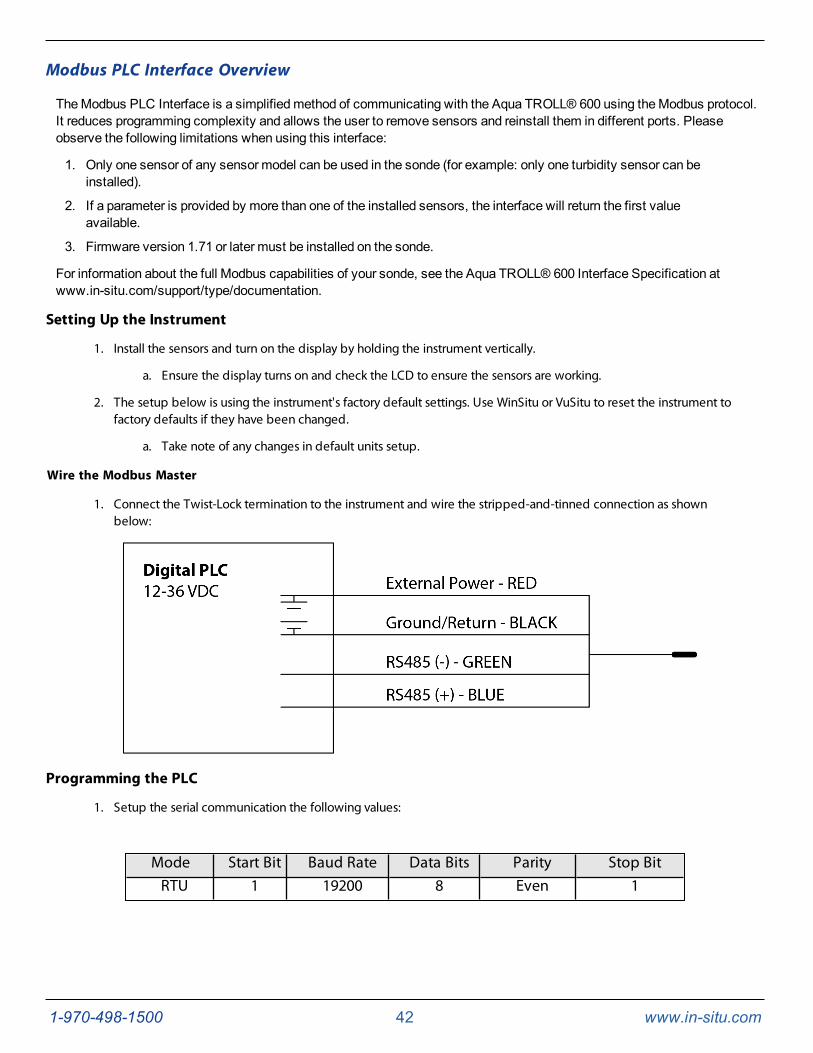
Wire the Modbus Master
1. Connect the Twist-Lock termination to the instrument and wire the stripped-and-tinned connection as shownbelow:
Programming the PLC
1. Setup the serial communication the following values:
Mode Start Bit Baud Rate Data Bits Parity Stop BitRTU 1 19200 8 Even 1
1-970-498-1500 43 www.in-situ.com
2. Set the device address to: 1
3. Set the PLC to wake-up the device by sending any Modbus command.
a. This could be a carriage return, reading the slave id or reading any register.
4. Read the discovery register using Appendix A to trigger the instrument to scan and map the sensors.
a. The return value can be discarded.
b. Each register is a holding register. Some PLCs require you to add 40000 to the register number oraddress. For example: 9301 would be 49301.
c. Alternatively, you can prompt the instrument to update its sensor mapping by performing any of thefollowing actions:
a. Activating the instrument's LCD screen;
b. Connecting to the instrument via VuSitu orWin-Situ software;
c. Running a log.
5. Select the register to read on the PLC using Appendix B
a. Some PLC devices use the register number directly in programming statements, others use registeraddresses, which are one less than the register number; the programmer must adhere to the PLC’sprogramming style
b. Each register is a holding register. Some PLCs require you to add 40000 to the register number oraddress. For example: 5451 would be 45451.
6. Set the type of register to: 32-bit float
a. If asked by the PLC this is 2 registers
7. Set the byte order to: Big Endean (MSB)
a. This should be the default and may not be configurable on all PLCs
Reading Parameters
To determine the starting register number for a given parameter register block, first determine its parameter ID by looking inthe sensor’s parameter tables. Then calculate the starting register number of the parameter block using the followingequation.
Starting Register = (Parameter ID – 1) x 7 + 5451
For example, for the Conductivity Sensor, the parameter id for specific conductivity is 10 (bit 9 will be set in register 6984 if itis available). The starting register number for the specific conductivity register block is thus (10 – 1) x 7 + 5451 = 5514.
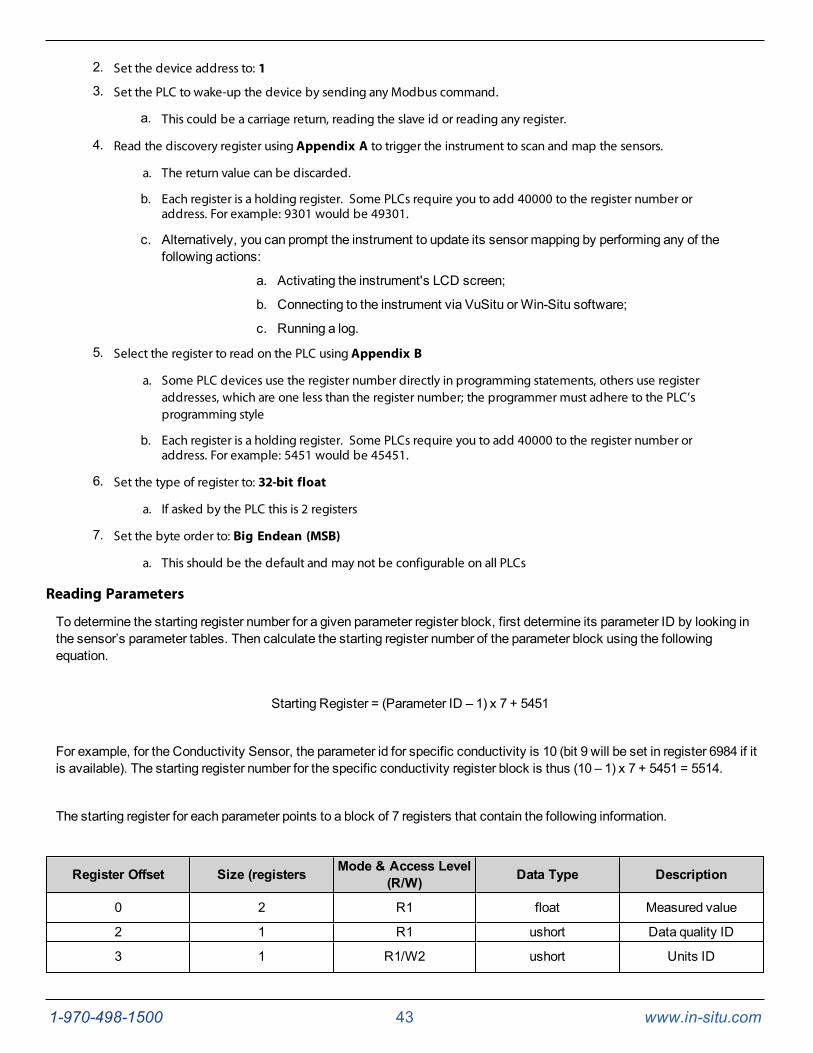
The starting register for each parameter points to a block of 7 registers that contain the following information.
Register Offset Size (registers Mode & Access Level(R/W) Data Type Description
0 2 R1 float Measured value
2 1 R1 ushort Data quality ID
3 1 R1/W2 ushort Units ID
1-970-498-1500 44 www.in-situ.com
4 1 R1 ushort Parameter ID
5 2 R1/W3 float Off line sentinel value
Continuing with the above example, to measure and read specific conductivity, read the two-register floating point value atregister 5514 (starting register 5514 + offset 0 = register 5514). To read the corresponding data quality id, read register 5516(starting register 5514 + offset 2 = register 5516). Block reads within the parameter block are allowed. The specificconductivity can bemeasured and read along with its data quality id by reading the 3 registers starting at register 5514, thenextracting themeasured float value and the data quality id.
Registers within the block that aremarked as read/write, can be written as well as read. Refer to the sensor-specificparameter information for valid values.
LCD Screen
LCD Screen
The AquaTROLL 600 includes an LCD screen that allows you to view instrument status and access sonde settings.
Turn on the LCD Screen
1. Hold the sonde vertically so the sensor end faces up.
2. The LCD screen will illuminate after a few seconds briefly displaying the platform name and firmware version,followed by the RDOSensor Cap expiration information (if applicable).
3. The LCD screen will then display port status, power status, log status, and connection status (when applicable).
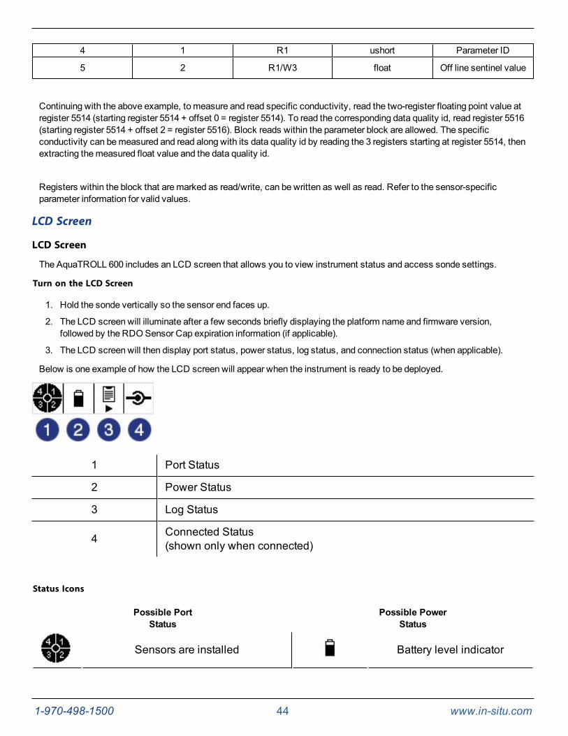
Below is one example of how the LCD screen will appear when the instrument is ready to be deployed.
1 Port Status
2 Power Status
3 Log Status
4 Connected Status(shown only when connected)
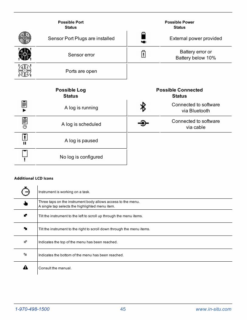
Status Icons
Possible PortStatus
Possible PowerStatus
Sensors are installed Battery level indicator
1-970-498-1500 45 www.in-situ.com
Possible PortStatus
Possible PowerStatus
Sensor Port Plugs are installed External power provided
Sensor error Battery error orBattery below 10%
Ports are open
Possible LogStatus
Possible ConnectedStatus
A log is running Connected to softwarevia Bluetooth
A log is scheduled Connected to softwarevia cable
A log is paused
No log is configured
Additional LCD Icons
Instrument is working on a task.
Three taps on the instrument body allows access to the menu.A single tap selects the highlighted menu item.
Tilt the instrument to the left to scroll up through the menu items.
Tilt the instrument to the right to scroll down through the menu items.
Indicates the top of the menu has been reached.
Indicates the bottom of the menu has been reached.
Consult the manual.
1-970-498-1500 46 www.in-situ.com
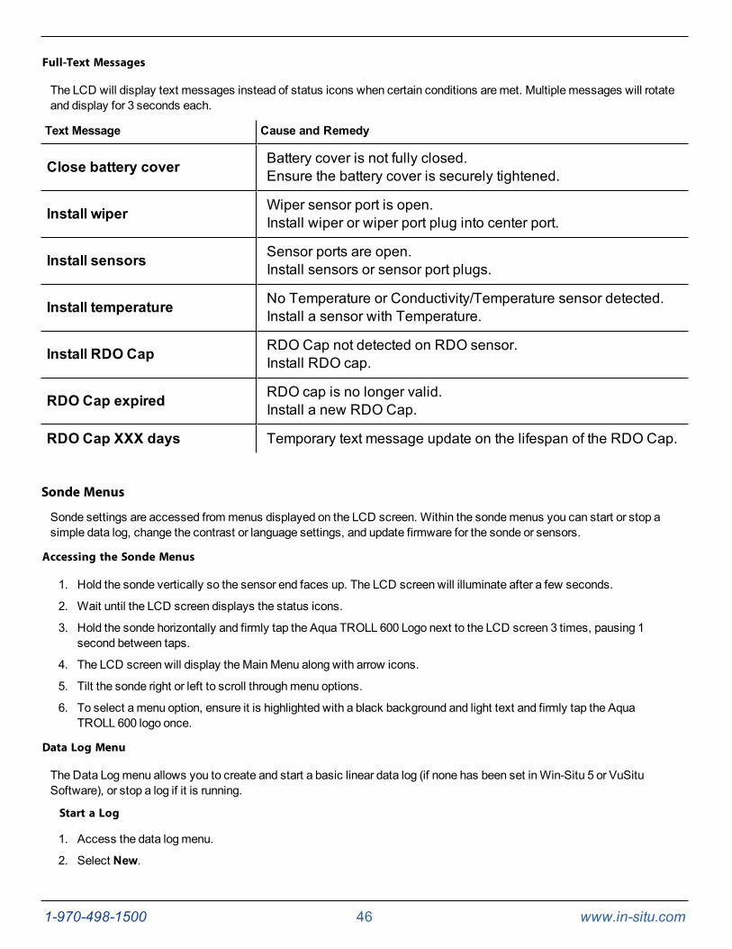
Full-Text Messages
The LCD will display text messages instead of status icons when certain conditions aremet. Multiple messages will rotateand display for 3 seconds each.
Text Message Cause and Remedy
Close battery cover Battery cover is not fully closed.Ensure the battery cover is securely tightened.
Install wiper Wiper sensor port is open.Install wiper or wiper port plug into center port.
Install sensors Sensor ports are open.Install sensors or sensor port plugs.
Install temperature No Temperature or Conductivity/Temperature sensor detected.Install a sensor with Temperature.
Install RDO Cap RDO Cap not detected on RDO sensor.Install RDO cap.
RDO Cap expired RDO cap is no longer valid.Install a new RDO Cap.
RDO Cap XXX days Temporary text message update on the lifespan of the RDO Cap.
Sonde Menus
Sonde settings are accessed frommenus displayed on the LCD screen. Within the sondemenus you can start or stop asimple data log, change the contrast or language settings, and update firmware for the sonde or sensors.
Accessing the Sonde Menus
1. Hold the sonde vertically so the sensor end faces up. The LCD screen will illuminate after a few seconds.
2. Wait until the LCD screen displays the status icons.
3. Hold the sonde horizontally and firmly tap the Aqua TROLL 600 Logo next to the LCD screen 3 times, pausing 1second between taps.
4. The LCD screen will display theMainMenu along with arrow icons.
5. Tilt the sonde right or left to scroll throughmenu options.
6. To select amenu option, ensure it is highlighted with a black background and light text and firmly tap the AquaTROLL 600 logo once.
Data Log Menu
The Data Logmenu allows you to create and start a basic linear data log (if none has been set inWin-Situ 5 or VuSituSoftware), or stop a log if it is running.
Start a Log
1. Access the data logmenu.
2. Select New.
1-970-498-1500 47 www.in-situ.com
3. Select the desired reading interval. The data log will start once the interval is selected.
The data log will appear inWin-Situ with the Log Name "Aqua TROLL 600 SERIAL NUMBER," where SERIAL NUMBERwill be the serial number of the unit. This log records all sensors and parameters and is a no wrap log. This means once thedata capacity is reached the log will stop.
You are unable to update the instrument firmware while a log is running. Stop a log toupdate the sonde or sensors.
Stop a Log
1. Access the Data Logmenu.
2. Select Stop.
3. Select Yes. The data log will stop.
Contrast Menu
The Contrast Menu allows you to adjust the contrast on the LCD screen.
1. Access the Contrast menu.
2. Tilt the sonde left to decrease (lighten) the contrast, or right to increase (darken) the contrast.
3. Tap the Aqua TROLL 600 logo to set the selected contrast.
Language Menu
The LanguageMenu allows you to set the default display language of the LCD screen.
1. Access the Languagemenu.
2. Highlight the desired language (English, Spanish, French, German).
3. Tap the Aqua TROLL 600 logo to set the selected language.
Updates Menu
The Updates Menu allows you to update firmware for the sonde or installed sensors.
1. Access the Updates menu.
2. Highlight the desired component to update (Sonde, Sensor 1 to 4).
If an update is present on the SD card, the screen will indicate the previous firmware version, aright-facing arrow, and the new version of the firmware.
3. Select Yes to update the firmware.
For more information on firmware updates, see "Updating Firmware" on page 48
Batteries
The Aqua TROLL 600 uses two standard D-cell 1.5 V alkaline batteries.
1-970-498-1500 48 www.in-situ.com
Battery Replacement
1. Open the battery compartment and remove both batteries.
2. Insert new batteries. Ensure the LCD screen turns on.
3. Replace the battery cover.
Never use lithium batteries, or batteries that are different ages or manufacturers.
In-Situ recommends using new batteries every time.
Micro SD Card
The Aqua TROLL 600 uses amicro SD card for data storage and updating sonde firmware. You can remove the SD card andreplace it with another for data download, or use the same card. An SD card is not required to log data.
Removing the Micro SD Card
Themicro SD card is housed in a slot near the positive battery terminal and the twist-lock connector.
1. Remove the battery cover from the end of the instrument.
2. Push themicro SD card in towards the instrument to release the card.
3. Remove the card from the slot.
4. To reinstall the card, note the card position diagram in the finger slot. Push the card into the slot until you hear aclick.
Downloading and Deleting Data from the Micro SD Card
1. Remove card from the sonde and insert it into amicro SD card adapter.
2. Insert the adapter into a PC or laptop.
3. Open themicro SD card using the file explorer.
4. Open the folder titled "Serial Number.LOG." For example, "424690.LOG."
Logs are named by date and then number. For example, a log started on November 12, 2015would be named "15111200.CSV" - 15 is the year, 11 is themonth, 12 is the day, and 00 is thelog number. If multiple logs are recorded on the same day the last number will increase by onefor each consecutive log.
5. Select the logs you wish to download andmove them to the destination.
6. Select the logs you wish to delete and press Delete on the keyboard. Deleted logs cannot be recovered.
Updating Firmware
1. Download the firmware update files to your computer.
2. Remove the SD card from the unit and insert it into your computer.
Youmay need amicro SD card adapter to connect the SD card to your computer. One isincluded with your Aqua TROLL 600, but any micro SD card adapter can be used.
3. Copy the firmware update files into the ISI.FW file on the SD card.
1-970-498-1500 49 www.in-situ.com
4. Install the SD card into the instrument and install the battery cover.
5. Turn on the LCD screen by inverting the sonde so the sensor end faces up.
6. Access the instrument menu by tapping the Aqua TROLL 600 logo on the yellow label three times. For moreinformation on accessingmenus, see "LCD Screen" on page 44
7. Scroll toUpdates by tilting the instrument. Access the Updates menu by tapping the Aqua TROLL 600 logo once.
8. Scroll toSonde by tilting the instrument. Tap the Aqua TROLL 600 logo once.
9. The LCD screen will display the current firmware version on the left, then an arrow, and the new firmware versionon the right.
10. Scroll toYes by tilting the instrument. Tap the Aqua TROLL 600 logo once.
11. The LCD screen will display icons while updating. Once the update is complete the Aqua TROLL 600 and LCDscreen will restart.
Desiccant
The Aqua TROLL 600 contains a small, replaceable desiccant capsule in the battery compartment. This capsule preventsmoisture from causing damage to the electronic components. It is filled with color-indicating silica that gradually changesfrom purple to pink as the desiccant's effectiveness decreases. Replace the desiccant when the desiccant has turned pink.The desiccant is included in the Aqua TROLL 600Maintenance Kit (0078940).
Replace the Desiccant
1. Remove the battery cover.
2. Remove the backup wrench tool from the back of the battery compartment.
3. Insert the backup wrench into the small hole on the back side of the battery compartment and push the desiccantcapsule out.
4. Insert a new desiccant capsule and push the capsule in fully using the wrench.
Sensor Calibration
Recommended Calibration Equipment, Accessories and Solutions
Laboratory/Office Calibration
l Instrument with Restrictor and Cable Connection Protector
l Ring Stand or Bucket to hold instrument
l Calibration Solutions
l RDOCalibration Sponge or 100% Saturation Bubbler
l Running water or DI Squirt Bottle
l Sink
l Paper Towels
Field Calibration
l Instrument with Restrictor and Cable Connection Protector
l Ring Stand or Bucket to hold instrument
1-970-498-1500 50 www.in-situ.com
l Calibration Solutions
l RDOCalibration Sponge or 100% Saturation Bubbler
l DI Squirt Bottle or Bucket of Water
l Paper Towels
Solution Based Calibration Preparation, Procedure and Rinsing
Check the instrument storage requirements in the Aqua TROLL 600 manual prior tostarting calibration.
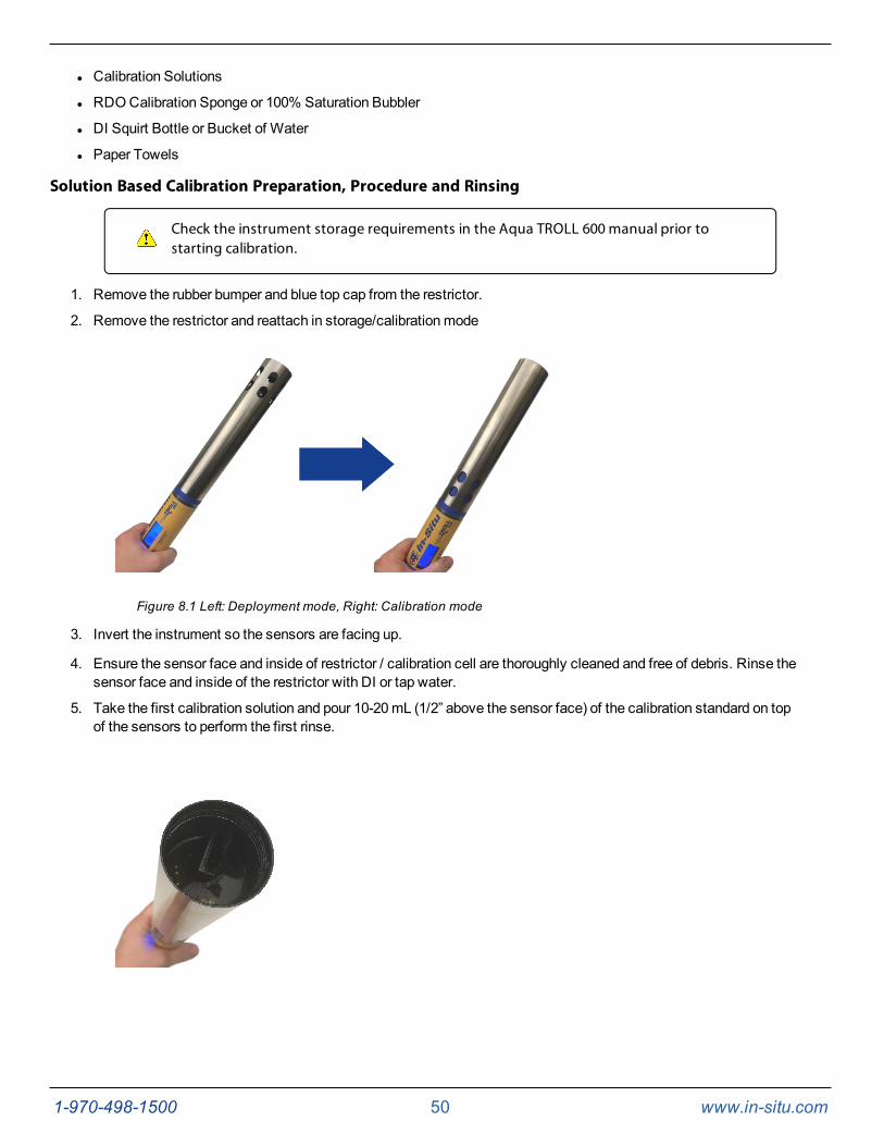
1. Remove the rubber bumper and blue top cap from the restrictor.
2. Remove the restrictor and reattach in storage/calibrationmode
Figure 8.1 Left: Deployment mode, Right: Calibration mode
3. Invert the instrument so the sensors are facing up.
4. Ensure the sensor face and inside of restrictor / calibration cell are thoroughly cleaned and free of debris. Rinse thesensor face and inside of the restrictor with DI or tap water.
5. Take the first calibration solution and pour 10-20mL (1/2” above the sensor face) of the calibration standard on topof the sensors to perform the first rinse.
1-970-498-1500 51 www.in-situ.com
6. Move the solution in the calibration cell to ensure it has been in contact with the surface of the sensors and theinside of the calibration cell. If necessary, reinstall the blue top cap and gently shake.
7. Discard the rinse calibration solution.
8. Repeat steps 5-7. (Note: for best calibration, it is necessary to rinse twice with the calibration solution to ensure allcontaminants have been removed and the solution has dampened the sensor face).
9. With the sonde and sensors still inverted, fill the calibration cell with 40-50mL (to the bottom of the threads inside ofthe restrictor) of fresh calibration solution. Make sure that the calibration solution is approximately 1 inch above thesurface of the sensor face. Check the sensors for bubbles. Gently tap on the surface to remove any bubbles.
10. Perform the sensor calibration using VuSitu Mobile app orWin-Situ 5 software.
11. Between new sensor calibrations or when performing amulti-point user calibration, remove the restrictor andthoroughly rinse the sensors and restrictor with water. Repeat solution rinse procedure (steps 5-7) prior to addingfresh calibration solution. Alternatively, leave the restrictor in place and rinse the sensors thoroughly with deionizedwater to remove all calibration standard. Rinse twice with calibration standard.
Not removing all of the previous calibration solution can contaminate the next solution, thusimpacting the accuracy of the next calibration or causemuch slower sensor response.
Sensor calibration procedures vary slightly based on the software you are using to program theinstrument. If you are using the VuSitu Mobile App, See "About Calibration and Settings" onpage 65 If you are usingWin-Situ 5 Software, See "Calibrate Sensors" on page 101
RDO 100% Saturation Calibration
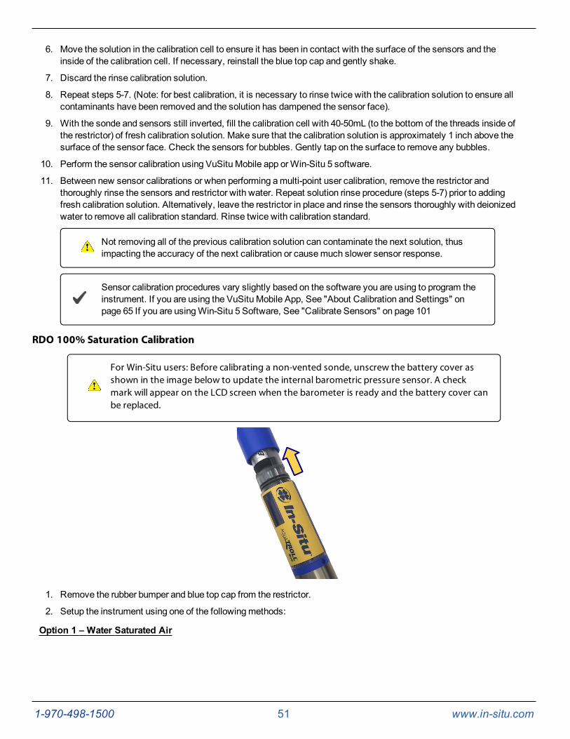
For Win-Situ users: Before calibrating a non-vented sonde, unscrew the battery cover asshown in the image below to update the internal barometric pressure sensor. A checkmark will appear on the LCD screen when the barometer is ready and the battery cover canbe replaced.
1. Remove the rubber bumper and blue top cap from the restrictor.
2. Setup the instrument using one of the followingmethods:
Option 1 – Water Saturated Air
1-970-498-1500 52 www.in-situ.com
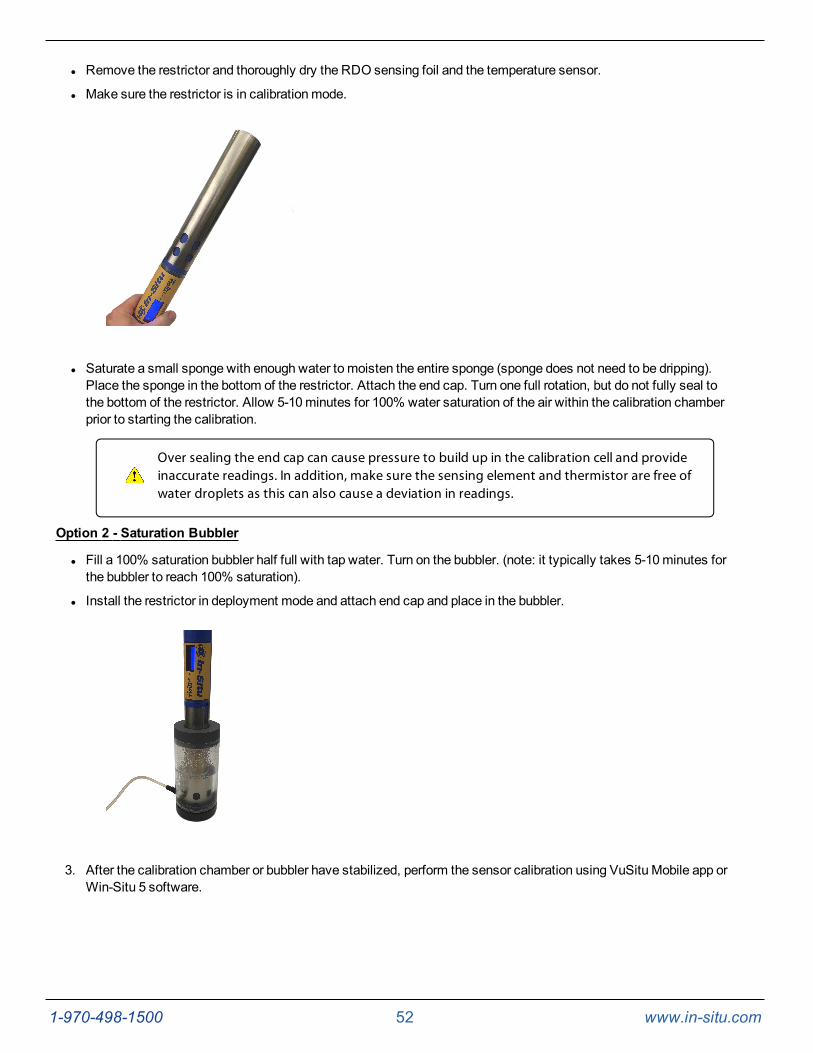
l Remove the restrictor and thoroughly dry the RDO sensing foil and the temperature sensor.
l Make sure the restrictor is in calibrationmode.
l Saturate a small sponge with enough water to moisten the entire sponge (sponge does not need to be dripping).Place the sponge in the bottom of the restrictor. Attach the end cap. Turn one full rotation, but do not fully seal tothe bottom of the restrictor. Allow 5-10minutes for 100% water saturation of the air within the calibration chamberprior to starting the calibration.
Over sealing the end cap can cause pressure to build up in the calibration cell and provideinaccurate readings. In addition, make sure the sensing element and thermistor are free ofwater droplets as this can also cause a deviation in readings.
Option 2 - Saturation Bubbler
l Fill a 100% saturation bubbler half full with tap water. Turn on the bubbler. (note: it typically takes 5-10minutes forthe bubbler to reach 100% saturation).
l Install the restrictor in deployment mode and attach end cap and place in the bubbler.
3. After the calibration chamber or bubbler have stabilized, perform the sensor calibration using VuSitu Mobile app orWin-Situ 5 software.
1-970-498-1500 53 www.in-situ.com
Verification of Calibration Accuracy
1. To verify the accuracy of the calibration, make sure that all solution has been removed from the sensors byremoving the restrictor/calibration cell and rinsing in a large bucket of fresh tap water or distilled water.
2. Take the same calibration solution that was used to perform the calibration and pour 10-20mL of the standard ontop of the sensors to perform the first rinse.
3. Reinstall the blue top cap and gently shake to ensure all sensors and inside of the calibration cell have been incontact with the calibration solution.
4. Discard the rinse calibration solution.
5. Repeat steps 2-4. (Note: for best calibration, it is necessary to rinse twice with the calibration solution to ensure allcontaminants have been removed and the solution has wetted the sensor face).
6. With the sonde and sensors still inverted, fill the restrictor with 40-50mL of fresh calibration solution. Make surethat the calibration solution is 1 inch above the surface of the sensor face. Check the sensors for bubbles. Gentlytap on the surface to remove any bubbles.
7. Open the software and take a few readings to ensure the reading from the sensor is fully stabilized. Verify that thereadingmatches the expected value located on the outside of the calibration solution. If outside of sensorspecifications, recalibrate.
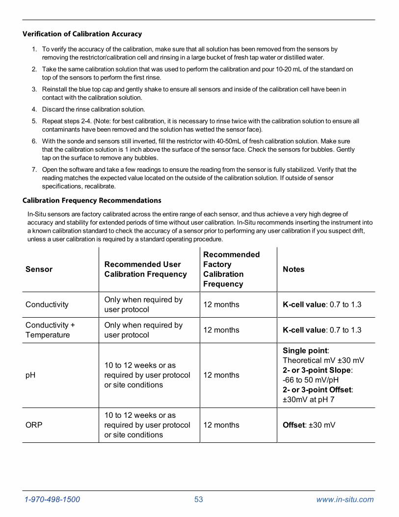
Calibration Frequency Recommendations
In-Situ sensors are factory calibrated across the entire range of each sensor, and thus achieve a very high degree ofaccuracy and stability for extended periods of time without user calibration. In-Situ recommends inserting the instrument intoa known calibration standard to check the accuracy of a sensor prior to performing any user calibration if you suspect drift,unless a user calibration is required by a standard operating procedure.
Sensor Recommended UserCalibration Frequency
RecommendedFactoryCalibrationFrequency
Notes
Conductivity Only when required byuser protocol 12 months K-cell value: 0.7 to 1.3
Conductivity +Temperature
Only when required byuser protocol 12 months K-cell value: 0.7 to 1.3
pH10 to 12 weeks or asrequired by user protocolor site conditions
12 months
Single point:Theoretical mV ±30 mV2- or 3-point Slope:-66 to 50 mV/pH2- or 3-point Offset:±30mV at pH 7
ORP10 to 12 weeks or asrequired by user protocolor site conditions
12 months Offset: ±30 mV
1-970-498-1500 54 www.in-situ.com
RDO 12 months or as requiredby user protocol 12 months
2-point Slope:0.7 to 1.32-point Offset:±0.3 mg/L
Temperature Only when required byuser protocol
Only when requiredby user protocol Offset: ±0.5
Turbidity Only when required byuser protocol 12 months Slope: 0.7 to 1.3
Pressure/Depth Only when required byuser protocol
Only when requiredby user protocol
<2 times the full scaleaccuracy specification
Barometer Only when required byuser protocol
Only when requiredby user protocol
<2 times the full scaleaccuracy specification
Ammonium Monthly N/A Slope < -20 mV/decade
Chloride Monthly N/A Slope < -20 mV/decade
Nitrate Monthly N/A Slope < -20 mV/decade
Chlorophyll a Only when required byuser protocol 12 months
BGA-PC Only when required byuser protocol 12 months
BGA-PE Only when required byuser protocol 12 months
Rhodamine WT Only when required byuser protocol 12 months
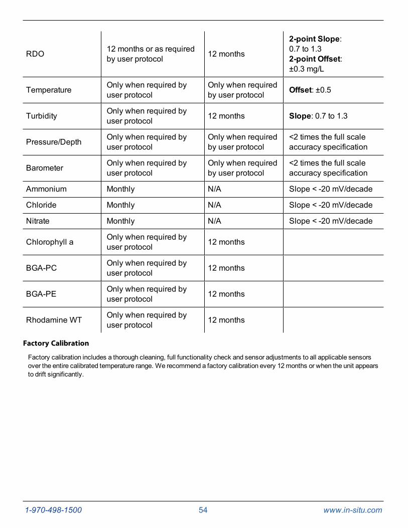
Factory Calibration
Factory calibration includes a thorough cleaning, full functionality check and sensor adjustments to all applicable sensorsover the entire calibrated temperature range. We recommend a factory calibration every 12months or when the unit appearsto drift significantly.
1-970-498-1500 55 www.in-situ.com
Zeroing the Depth Sensor
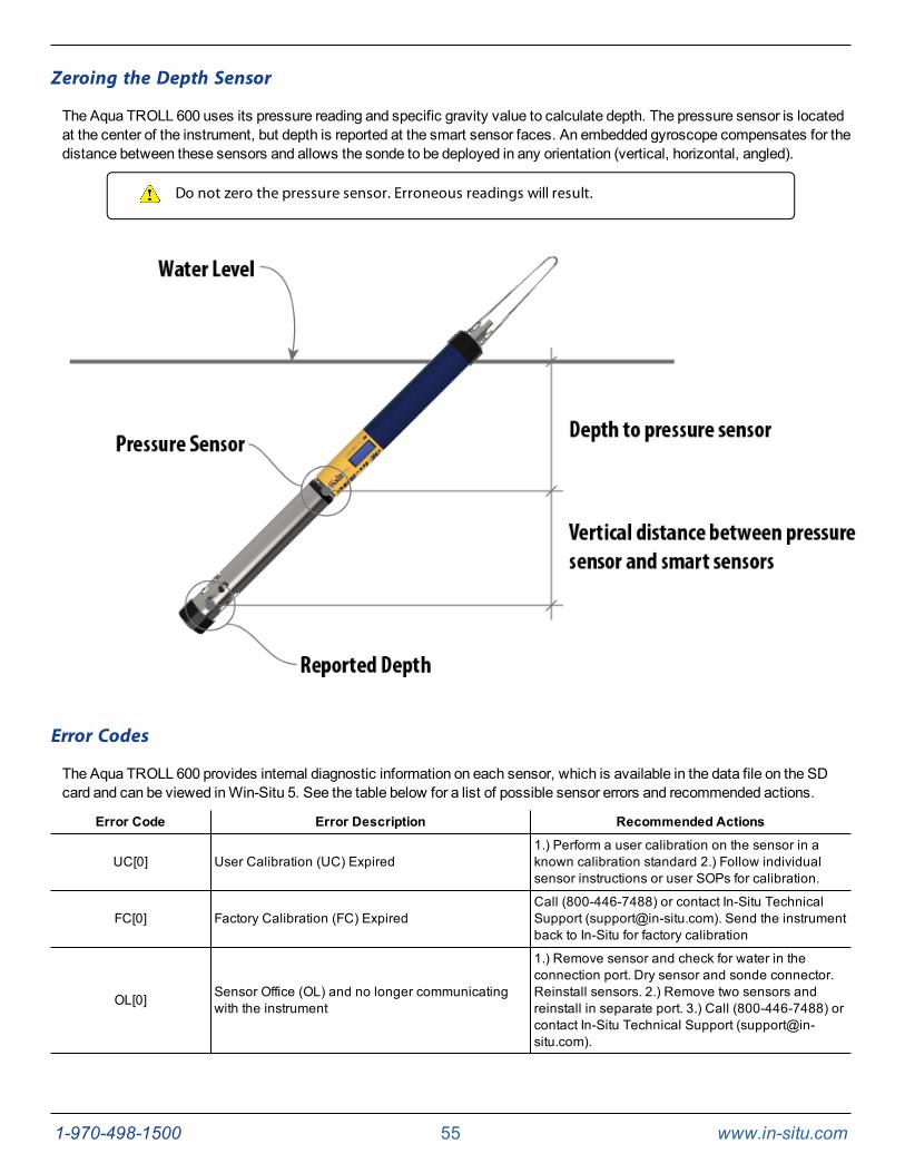
The Aqua TROLL 600 uses its pressure reading and specific gravity value to calculate depth. The pressure sensor is locatedat the center of the instrument, but depth is reported at the smart sensor faces. An embedded gyroscope compensates for thedistance between these sensors and allows the sonde to be deployed in any orientation (vertical, horizontal, angled).
Do not zero the pressure sensor. Erroneous readings will result.
Error Codes
The Aqua TROLL 600 provides internal diagnostic information on each sensor, which is available in the data file on the SDcard and can be viewed inWin-Situ 5. See the table below for a list of possible sensor errors and recommended actions.
Error Code Error Description Recommended Actions
UC[0] User Calibration (UC) Expired1.) Perform a user calibration on the sensor in aknown calibration standard 2.) Follow individualsensor instructions or user SOPs for calibration.
FC[0] Factory Calibration (FC) ExpiredCall (800-446-7488) or contact In-Situ TechnicalSupport ([email protected]). Send the instrumentback to In-Situ for factory calibration
OL[0] Sensor Office (OL) and no longer communicatingwith the instrument
1.) Remove sensor and check for water in theconnection port. Dry sensor and sonde connector.Reinstall sensors. 2.) Remove two sensors andreinstall in separate port. 3.) Call (800-446-7488) orcontact In-Situ Technical Support ([email protected]).
1-970-498-1500 56 www.in-situ.com
WU[0] Wiper Error - wiper is not turning correctly orinterfering with sensor performance
1.) Inspect wiper to ensure surface is free of debrisand the wiper is spinning correctly. 2.) Removewiper brush and install a new brush holder with newbrushes. 3.) Remove the wiper and check for waterin the connection port. Dry the wiper port and thesonde connector. Reinstall wiper. 3.) Call (800-446-7488) or contact In-Situ Technical Support([email protected]).
ERR[0] Sensor is performing outside of expected range
1.) Make sure the sensor is submerged in solution.2.) Recalibrate sensor in a fresh batch of calibrationstandard. 3.) Reset sensor back to factory defaultsand check reading in a calibration standard.Recalibrate. 4.) Call (800-446-7488) or contact In-Situ Technical Support ([email protected]).
DIS[0]Sensor is not set up correctly, being used outside oftemperature or sensor range or returning a sentinelvalue due to internal malfunction or damage
1.) Verify that the RDO sensor cap is installed, thesensing foil is intact and the cap has not expired.2.)Clean the surface of the sensor to remove anyexcess debris 3.) Verify that the instrument andsensors are not being used outside of temperatureor sensor specifications. 4.) Verify that the sensor isnot physically damaged 5.) Call (800-446-7488) orcontact In-Situ Technical Support ([email protected]).
Software
TheAqua TROLL® 600 can be programmed using the VuSitu Mobile App for Android, or usingWin-Situ 5 Software.
VuSitu Mobile App
Verify the VuSitu Mobile App Version
To avoid potential compatibility issues, it is important to use themost recent version of the VuSitu Mobile App. Find versioninformation and app updates from theGoogle Play Store.
Connecting with Bluetooth
The Aqua TROLL® 600 can connect to a Bluetooth-enabled device for wireless communication with the VuSitu Mobile App orWin-Situ 5.
Download VuSitu from the Google Play Store at https://play.google.com.
1. Turn on the Aqua TROLL 600 LCD screen by holding the sonde vertical with the sensor end facing up.
2. On the Bluetooth-enabled device, navigate to the Bluetoothmenu and scan for available devices.
3. The Aqua TROLL 600 will be listed as "Serial Number - AT600". For example: 424690 - AT600. Tap the devicename to pair the Aqua TROLL 600 and the Bluetooth-enabled device.
Connecting to VuSitu
1. Open the VuSitu Mobile App. If you have correctly paired your Aqua TROLL® 600 with your wireless device, andthe instrument is available, the software will connect and display readings.

1-970-498-1500 57 www.in-situ.com
If the Searching screen continues to show, tap Choose another device and select the deviceyou are trying to connect to.
Connecting to Win-Situ 5
1. OpenWin-Situ 5 Software.
2. When prompted, "Connect to device now?" click No.
3. Click Preferences, then click Comm Settings.
4. Select the correct Com port used by Bluetooth, then select the following settings:
l Baud: 19200
l Data Bits: 8
l Parity Bits: None
l Stop Bits: 1
l Device Address: 1
l Mode: Modbus-ASCII
5. Click the checkmark, then click the Connect button in the lower right hand corner.
VuSitu Overview
About VuSitu
VuSitu is themobile user interface and control application for In-Situ water quality instruments. You can use VuSitu onmobiledevices with Android operating system 4.4, Bluetooth 2.0 and newer. Download the latest version of the app from theGooglePlay Store at play.google.com.
VuSitu allows you to accomplish the following tasks.
l View live readings that update every 10 seconds
l Change parameters and units
l Set up a data log
l Record data
l Email data in spreadsheet format
l Download data tomobile device
l Transfer data frommobile device to a computer
l Organize data by Location
l Calibrate Sensors and View Reports
VuSitu Menu Options
The features available in the VuSitu mobile app vary slightly depending on the instrument to which it is connected. Tap themenu icon in the upper left portion of the screen to view the features included in VuSitu. Tap themenu icon again to close themenu.
Menu Options when Connected to Instrument
Some features, such as sensor calibration, are not available when you are not connected to an instrument.
1-970-498-1500 58 www.in-situ.com
1-970-498-1500 59 www.in-situ.com
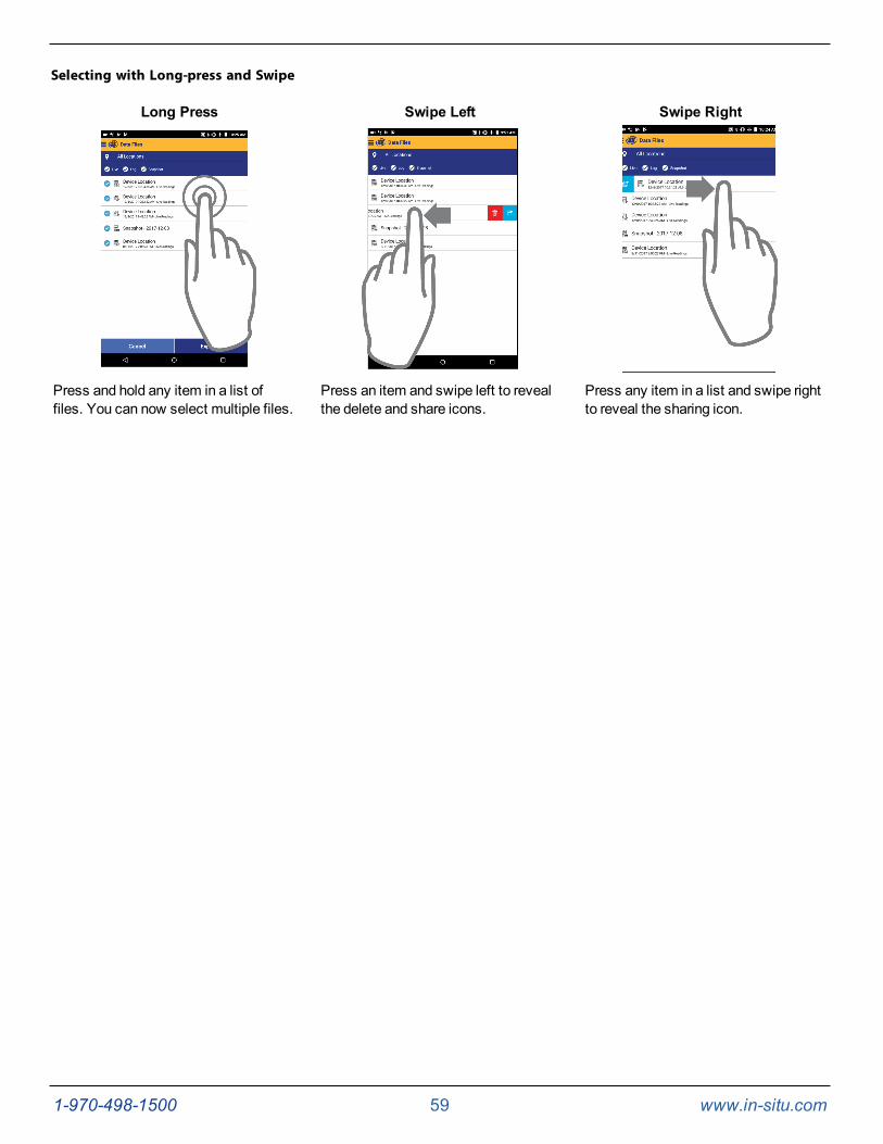
Selecting with Long-press and Swipe
Long Press Swipe Left Swipe Right
Press and hold any item in a list offiles. You can now select multiple files.
Press an item and swipe left to revealthe delete and share icons.
Press any item in a list and swipe rightto reveal the sharing icon.
1-970-498-1500 60 www.in-situ.com
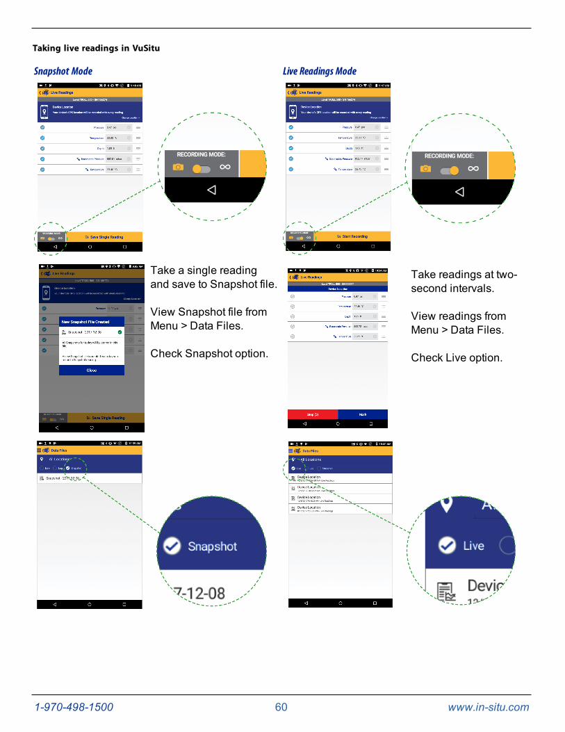
Taking live readings in VuSitu
Snapshot Mode Live Readings Mode
Take a single readingand save to Snapshot file.
View Snapshot file fromMenu > Data Files.
Check Snapshot option.
Take readings at two-second intervals.
View readings fromMenu > Data Files.
Check Live option.
1-970-498-1500 61 www.in-situ.com
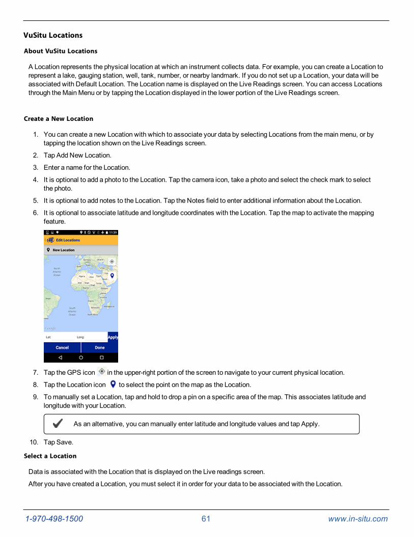
VuSitu Locations
About VuSitu Locations
A Location represents the physical location at which an instrument collects data. For example, you can create a Location torepresent a lake, gauging station, well, tank, number, or nearby landmark. If you do not set up a Location, your data will beassociated with Default Location. The Location name is displayed on the Live Readings screen. You can access Locationsthrough theMainMenu or by tapping the Location displayed in the lower portion of the Live Readings screen.
Create a New Location
1. You can create a new Location with which to associate your data by selecting Locations from themainmenu, or bytapping the location shown on the Live Readings screen.
2. Tap Add New Location.
3. Enter a name for the Location.
4. It is optional to add a photo to the Location. Tap the camera icon, take a photo and select the check mark to selectthe photo.
5. It is optional to add notes to the Location. Tap the Notes field to enter additional information about the Location.
6. It is optional to associate latitude and longitude coordinates with the Location. Tap themap to activate themappingfeature.
7. Tap theGPS icon in the upper-right portion of the screen to navigate to your current physical location.
8. Tap the Location icon to select the point on themap as the Location.
9. Tomanually set a Location, tap and hold to drop a pin on a specific area of themap. This associates latitude andlongitude with your Location.
As an alternative, you canmanually enter latitude and longitude values and tap Apply.
10. Tap Save.
Select a Location
Data is associated with the Location that is displayed on the Live readings screen.
After you have created a Location, youmust select it in order for your data to be associated with the Location.
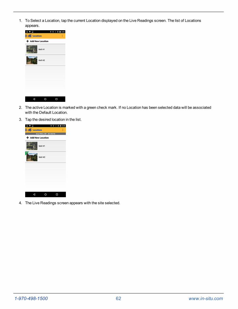
1-970-498-1500 62 www.in-situ.com
1. To Select a Location, tap the current Location displayed on the Live Readings screen. The list of Locationsappears.
2. The active Location is marked with a green check mark. If no Location has been selected data will be associatedwith the Default Location.
3. Tap the desired location in the list.
4. The Live Readings screen appears with the site selected.
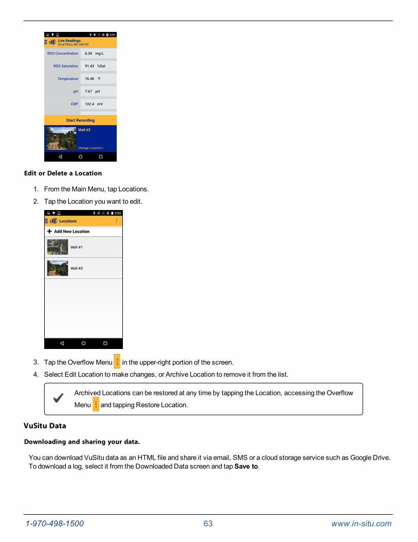
1-970-498-1500 63 www.in-situ.com
Edit or Delete a Location
1. From theMainMenu, tap Locations.
2. Tap the Location you want to edit.
3. Tap the Overflow Menu in the upper-right portion of the screen.
4. Select Edit Location tomake changes, or Archive Location to remove it from the list.
Archived Locations can be restored at any time by tapping the Location, accessing the Overflow
Menu and tapping Restore Location.
VuSitu Data
Downloading and sharing your data.
You can download VuSitu data as an HTML file and share it via email, SMS or a cloud storage service such as Google Drive.To download a log, select it from the Downloaded Data screen and tapSave to.

1-970-498-1500 64 www.in-situ.com
Choose one of the download options from themenu. You can transfer a data file from your mobile device to a PC viaBluetooth, email it to yourself or any valid email address, save the file to the VuSitu folder on your device or upload it toGoogle Drive.
View your data in any web browser by double-clicking the file. You can then export a CSV file by clicking theExport a CSVlink at the top of the page.

1-970-498-1500 65 www.in-situ.com
VuSitu Calibration & Settings
About Calibration and Settings
You can perform sensor calibrations, view a calibration report, or restore factory calibration defaults when the instrument isconnected to VuSitu.
1. Tap the VuSitu menu icon, and select Connected Instrument from the list.
2. Tap Calibrations.
3. Calibrations and settings for all connected sensors will appear. Ammonium, chloride and nitrate parameters are notshown in the image below but are displayed when the corresponding sensors are installed.
4. Tap the calibration you want to perform.
You can also access the full Calibration Report from this menu.
Quick-Cal Multiple Sensor Calibration
Quick-Cal allows you to perform a one-point calibration on up to three sensors with one setup and stabilization process.
1. From themainmenu, select Connected Instrument.
2. Select Calibrations.
3. From the CalibrationMenu, select Quick-Cal (multi-sensor).
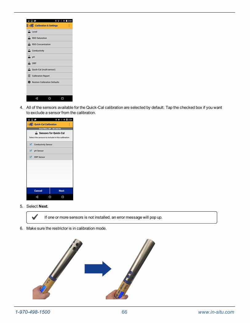
1-970-498-1500 66 www.in-situ.com
4. All of the sensors available for the Quick-Cal calibration are selected by default. Tap the checked box if you wantto exclude a sensor from the calibration.
5. Select Next.
If one or more sensors is not installed, an error message will pop up.
6. Make sure the restrictor is in calibrationmode.
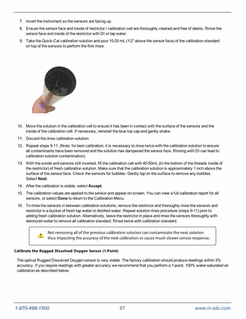
1-970-498-1500 67 www.in-situ.com
7. Invert the instrument so the sensors are facing up.
8. Ensure the sensor face and inside of restrictor / calibration cell are thoroughly cleaned and free of debris. Rinse thesensor face and inside of the restrictor with DI or tap water.
9. Take the Quick-Cal calibration solution and pour 10-20mL (1/2” above the sensor face) of the calibration standardon top of the sensors to perform the first rinse.
10. Move the solution in the calibration cell to ensure it has been in contact with the surface of the sensors and theinside of the calibration cell. If necessary, reinstall the blue top cap and gently shake.
11. Discard the rinse calibration solution.
12. Repeat steps 9-11. (Note: for best calibration, it is necessary to rinse twice with the calibration solution to ensureall contaminants have been removed and the solution has dampened the sensor face. Rinsing with DI can lead tocalibration solution contamination).
13. With the sonde and sensors still inverted, fill the calibration cell with 40-50mL (to the bottom of the threads inside ofthe restrictor) of fresh calibration solution. Make sure that the calibration solution is approximately 1 inch above thesurface of the sensor face. Check the sensors for bubbles. Gently tap on the surface to remove any bubbles.Select Next.
14. After the calibration is stable, select Accept.
15. The calibration values are applied to the sensor and appear on screen. You can view a full calibration report for allsensors, or select Done to return to the CalibrationMenu.
16. To rinse the sensors in between calibration solutions, remove the restrictor and thoroughly rinse the sensors andrestrictor in a bucket of fresh tap water or distilled water. Repeat solution rinse procedure (steps 9-11) prior toadding fresh calibration solution. Alternatively, leave the restrictor in place and rinse the sensors thoroughly withdeionized water to remove all calibration standard. Rinse twice with calibration standard.
Not removing all of the previous calibration solution can contaminate the next solutionthus impacting the accuracy of the next calibration or cause much slower sensor response.
Calibrate the Rugged Dissolved Oxygen Sensor (1-Point)
The optical Rugged DissolvedOxygen sensor is very stable. The factory calibration should produce readings within 3%accuracy. If you require readings with greater accuracy we recommend that you perform a 1-point, 100% water-saturated aircalibration as described below.
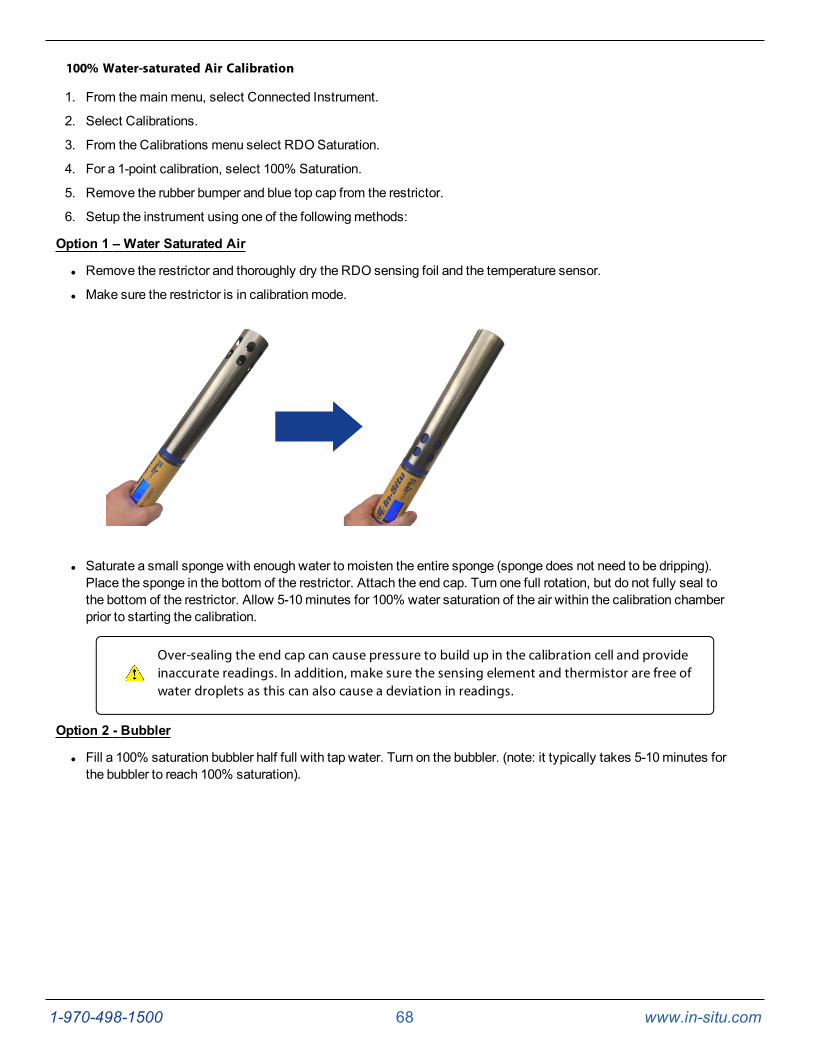
1-970-498-1500 68 www.in-situ.com
100% Water-saturated Air Calibration
1. From themainmenu, select Connected Instrument.
2. Select Calibrations.
3. From the Calibrations menu select RDOSaturation.
4. For a 1-point calibration, select 100% Saturation.
5. Remove the rubber bumper and blue top cap from the restrictor.
6. Setup the instrument using one of the followingmethods:
Option 1 – Water Saturated Air
l Remove the restrictor and thoroughly dry the RDO sensing foil and the temperature sensor.
l Make sure the restrictor is in calibrationmode.
l Saturate a small sponge with enough water to moisten the entire sponge (sponge does not need to be dripping).Place the sponge in the bottom of the restrictor. Attach the end cap. Turn one full rotation, but do not fully seal tothe bottom of the restrictor. Allow 5-10minutes for 100% water saturation of the air within the calibration chamberprior to starting the calibration.
Over-sealing the end cap can cause pressure to build up in the calibration cell and provideinaccurate readings. In addition, make sure the sensing element and thermistor are free ofwater droplets as this can also cause a deviation in readings.
Option 2 - Bubbler
l Fill a 100% saturation bubbler half full with tap water. Turn on the bubbler. (note: it typically takes 5-10minutes forthe bubbler to reach 100% saturation).
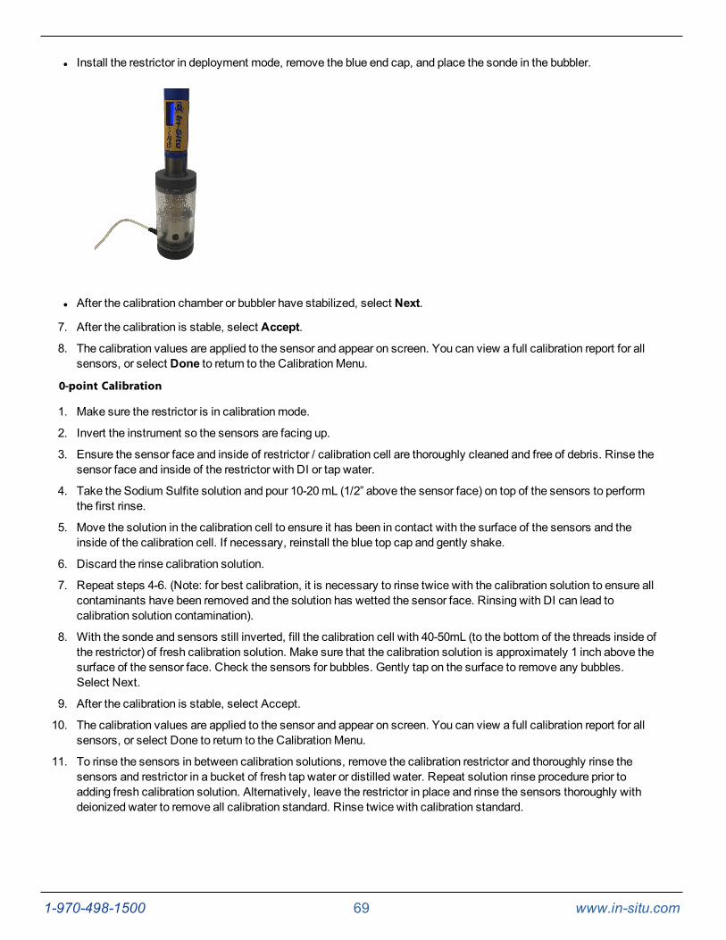
1-970-498-1500 69 www.in-situ.com
l Install the restrictor in deployment mode, remove the blue end cap, and place the sonde in the bubbler.
l After the calibration chamber or bubbler have stabilized, select Next.
7. After the calibration is stable, select Accept.
8. The calibration values are applied to the sensor and appear on screen. You can view a full calibration report for allsensors, or select Done to return to the CalibrationMenu.
0-point Calibration
1. Make sure the restrictor is in calibrationmode.
2. Invert the instrument so the sensors are facing up.
3. Ensure the sensor face and inside of restrictor / calibration cell are thoroughly cleaned and free of debris. Rinse thesensor face and inside of the restrictor with DI or tap water.
4. Take the Sodium Sulfite solution and pour 10-20mL (1/2” above the sensor face) on top of the sensors to performthe first rinse.
5. Move the solution in the calibration cell to ensure it has been in contact with the surface of the sensors and theinside of the calibration cell. If necessary, reinstall the blue top cap and gently shake.
6. Discard the rinse calibration solution.
7. Repeat steps 4-6. (Note: for best calibration, it is necessary to rinse twice with the calibration solution to ensure allcontaminants have been removed and the solution has wetted the sensor face. Rinsing with DI can lead tocalibration solution contamination).
8. With the sonde and sensors still inverted, fill the calibration cell with 40-50mL (to the bottom of the threads inside ofthe restrictor) of fresh calibration solution. Make sure that the calibration solution is approximately 1 inch above thesurface of the sensor face. Check the sensors for bubbles. Gently tap on the surface to remove any bubbles.Select Next.
9. After the calibration is stable, select Accept.
10. The calibration values are applied to the sensor and appear on screen. You can view a full calibration report for allsensors, or select Done to return to the CalibrationMenu.
11. To rinse the sensors in between calibration solutions, remove the calibration restrictor and thoroughly rinse thesensors and restrictor in a bucket of fresh tap water or distilled water. Repeat solution rinse procedure prior toadding fresh calibration solution. Alternatively, leave the restrictor in place and rinse the sensors thoroughly withdeionized water to remove all calibration standard. Rinse twice with calibration standard.
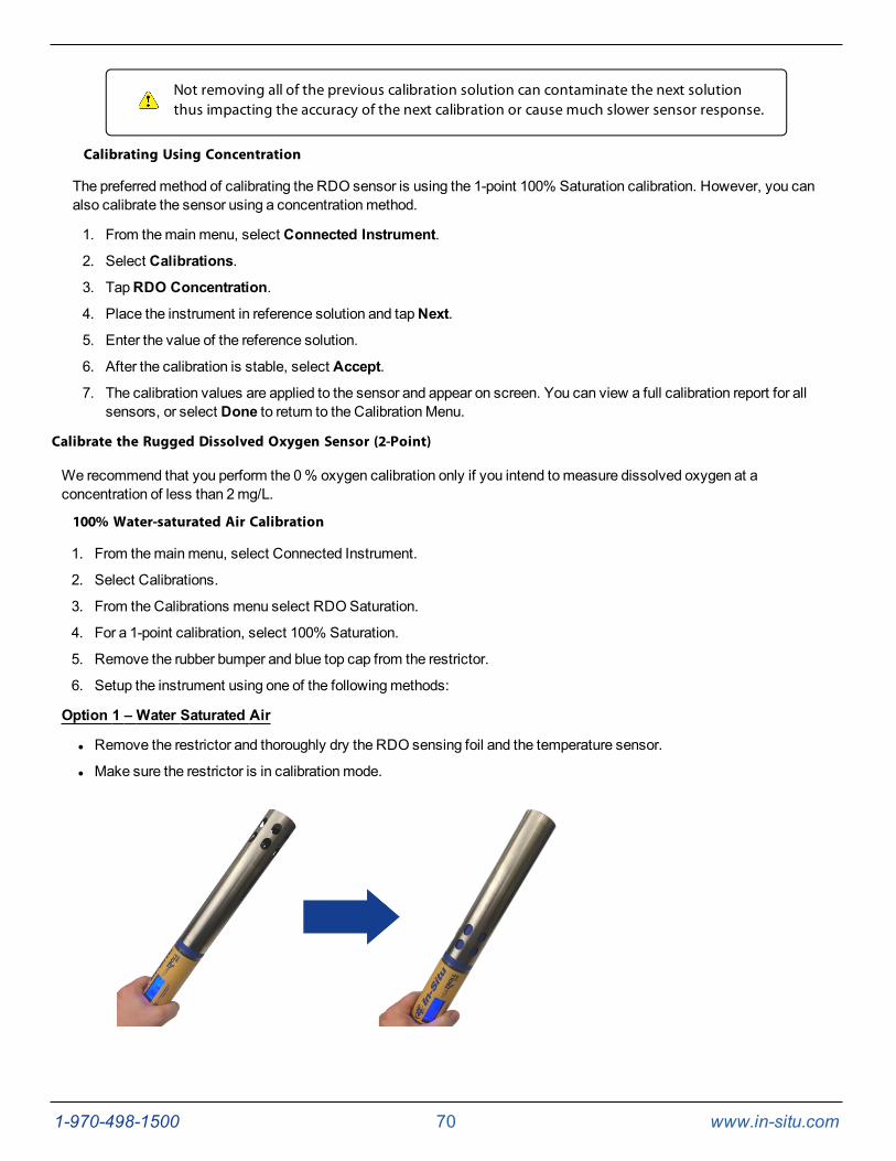
1-970-498-1500 70 www.in-situ.com
Not removing all of the previous calibration solution can contaminate the next solutionthus impacting the accuracy of the next calibration or cause much slower sensor response.
Calibrating Using Concentration
The preferredmethod of calibrating the RDO sensor is using the 1-point 100% Saturation calibration. However, you canalso calibrate the sensor using a concentrationmethod.
1. From themainmenu, select Connected Instrument.
2. Select Calibrations.
3. TapRDO Concentration.
4. Place the instrument in reference solution and tapNext.
5. Enter the value of the reference solution.
6. After the calibration is stable, select Accept.
7. The calibration values are applied to the sensor and appear on screen. You can view a full calibration report for allsensors, or select Done to return to the CalibrationMenu.
Calibrate the Rugged Dissolved Oxygen Sensor (2-Point)
We recommend that you perform the 0% oxygen calibration only if you intend tomeasure dissolved oxygen at aconcentration of less than 2mg/L.
100% Water-saturated Air Calibration
1. From themainmenu, select Connected Instrument.
2. Select Calibrations.
3. From the Calibrations menu select RDOSaturation.
4. For a 1-point calibration, select 100% Saturation.
5. Remove the rubber bumper and blue top cap from the restrictor.
6. Setup the instrument using one of the followingmethods:
Option 1 – Water Saturated Air
l Remove the restrictor and thoroughly dry the RDO sensing foil and the temperature sensor.
l Make sure the restrictor is in calibrationmode.
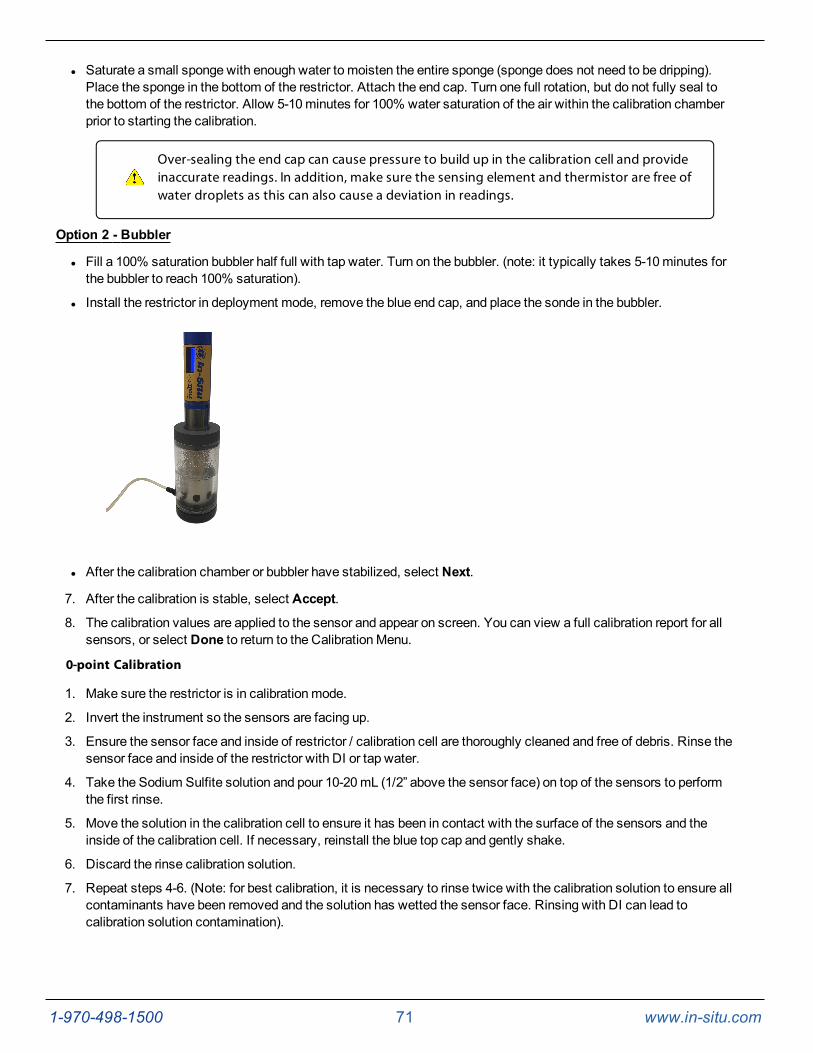
1-970-498-1500 71 www.in-situ.com
l Saturate a small sponge with enough water to moisten the entire sponge (sponge does not need to be dripping).Place the sponge in the bottom of the restrictor. Attach the end cap. Turn one full rotation, but do not fully seal tothe bottom of the restrictor. Allow 5-10minutes for 100% water saturation of the air within the calibration chamberprior to starting the calibration.
Over-sealing the end cap can cause pressure to build up in the calibration cell and provideinaccurate readings. In addition, make sure the sensing element and thermistor are free ofwater droplets as this can also cause a deviation in readings.
Option 2 - Bubbler
l Fill a 100% saturation bubbler half full with tap water. Turn on the bubbler. (note: it typically takes 5-10minutes forthe bubbler to reach 100% saturation).
l Install the restrictor in deployment mode, remove the blue end cap, and place the sonde in the bubbler.
l After the calibration chamber or bubbler have stabilized, select Next.
7. After the calibration is stable, select Accept.
8. The calibration values are applied to the sensor and appear on screen. You can view a full calibration report for allsensors, or select Done to return to the CalibrationMenu.
0-point Calibration
1. Make sure the restrictor is in calibrationmode.
2. Invert the instrument so the sensors are facing up.
3. Ensure the sensor face and inside of restrictor / calibration cell are thoroughly cleaned and free of debris. Rinse thesensor face and inside of the restrictor with DI or tap water.
4. Take the Sodium Sulfite solution and pour 10-20mL (1/2” above the sensor face) on top of the sensors to performthe first rinse.
5. Move the solution in the calibration cell to ensure it has been in contact with the surface of the sensors and theinside of the calibration cell. If necessary, reinstall the blue top cap and gently shake.
6. Discard the rinse calibration solution.
7. Repeat steps 4-6. (Note: for best calibration, it is necessary to rinse twice with the calibration solution to ensure allcontaminants have been removed and the solution has wetted the sensor face. Rinsing with DI can lead tocalibration solution contamination).
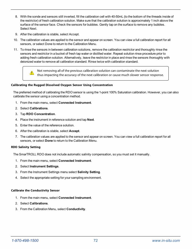
1-970-498-1500 72 www.in-situ.com
8. With the sonde and sensors still inverted, fill the calibration cell with 40-50mL (to the bottom of the threads inside ofthe restrictor) of fresh calibration solution. Make sure that the calibration solution is approximately 1 inch above thesurface of the sensor face. Check the sensors for bubbles. Gently tap on the surface to remove any bubbles.Select Next.
9. After the calibration is stable, select Accept.
10. The calibration values are applied to the sensor and appear on screen. You can view a full calibration report for allsensors, or select Done to return to the CalibrationMenu.
11. To rinse the sensors in between calibration solutions, remove the calibration restrictor and thoroughly rinse thesensors and restrictor in a bucket of fresh tap water or distilled water. Repeat solution rinse procedure prior toadding fresh calibration solution. Alternatively, leave the restrictor in place and rinse the sensors thoroughly withdeionized water to remove all calibration standard. Rinse twice with calibration standard.
Not removing all of the previous calibration solution can contaminate the next solutionthus impacting the accuracy of the next calibration or cause much slower sensor response.
Calibrating the Rugged Dissolved Oxygen Sensor Using Concentration
The preferredmethod of calibrating the RDO sensor is using the 1-point 100% Saturation calibration. However, you can alsocalibrate the sensor using a concentrationmethod.
1. From themainmenu, select Connected Instrument.
2. Select Calibrations.
3. TapRDO Concentration.
4. Place the instrument in reference solution and tapNext.
5. Enter the value of the reference solution.
6. After the calibration is stable, select Accept.
7. The calibration values are applied to the sensor and appear on screen. You can view a full calibration report for allsensors, or select Done to return to the CalibrationMenu.
RDO Salinity Setting
The SmarTROLLRDO does not include automatic salinity compensation, so youmust set it manually.
1. From themainmenu, select Connected Instrument.
2. Select Instrument Settings.
3. From the Instrument Settings menu select Salinity Setting.
4. Select the appropriate setting for your sampling environment.
Calibrate the Conductivity Sensor
1. From themainmenu, select Connected Instrument.
2. Select Calibrations.
3. From the CalibrationMenu, select Conductivity.
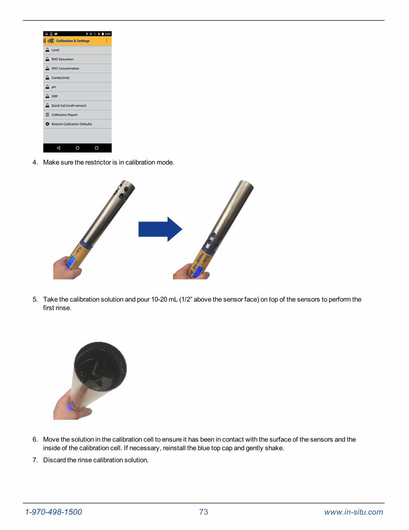
1-970-498-1500 73 www.in-situ.com
4. Make sure the restrictor is in calibrationmode.
5. Take the calibration solution and pour 10-20mL (1/2” above the sensor face) on top of the sensors to perform thefirst rinse.
6. Move the solution in the calibration cell to ensure it has been in contact with the surface of the sensors and theinside of the calibration cell. If necessary, reinstall the blue top cap and gently shake.
7. Discard the rinse calibration solution.
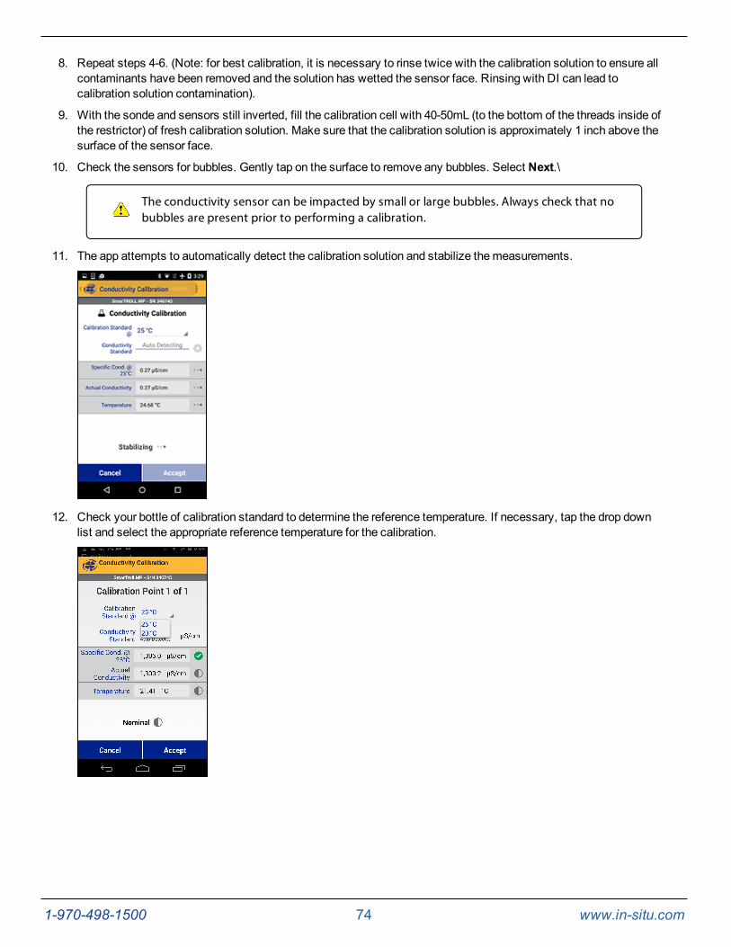
1-970-498-1500 74 www.in-situ.com
8. Repeat steps 4-6. (Note: for best calibration, it is necessary to rinse twice with the calibration solution to ensure allcontaminants have been removed and the solution has wetted the sensor face. Rinsing with DI can lead tocalibration solution contamination).
9. With the sonde and sensors still inverted, fill the calibration cell with 40-50mL (to the bottom of the threads inside ofthe restrictor) of fresh calibration solution. Make sure that the calibration solution is approximately 1 inch above thesurface of the sensor face.
10. Check the sensors for bubbles. Gently tap on the surface to remove any bubbles. Select Next.\
The conductivity sensor can be impacted by small or large bubbles. Always check that nobubbles are present prior to performing a calibration.
11. The app attempts to automatically detect the calibration solution and stabilize themeasurements.
12. Check your bottle of calibration standard to determine the reference temperature. If necessary, tap the drop downlist and select the appropriate reference temperature for the calibration.
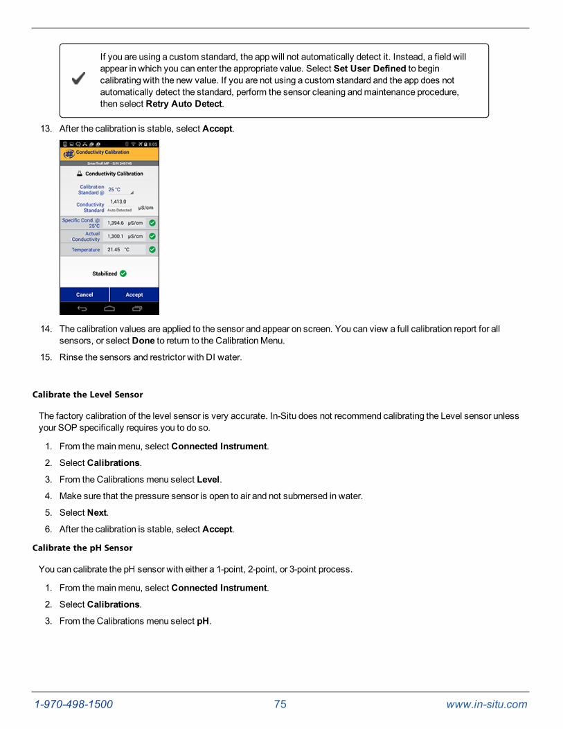
1-970-498-1500 75 www.in-situ.com
If you are using a custom standard, the app will not automatically detect it. Instead, a field willappear in which you can enter the appropriate value. Select Set User Defined to begincalibrating with the new value. If you are not using a custom standard and the app does notautomatically detect the standard, perform the sensor cleaning andmaintenance procedure,then select Retry Auto Detect.
13. After the calibration is stable, select Accept.
14. The calibration values are applied to the sensor and appear on screen. You can view a full calibration report for allsensors, or select Done to return to the CalibrationMenu.
15. Rinse the sensors and restrictor with DI water.
Calibrate the Level Sensor
The factory calibration of the level sensor is very accurate. In-Situ does not recommend calibrating the Level sensor unlessyour SOP specifically requires you to do so.
1. From themainmenu, select Connected Instrument.
2. Select Calibrations.
3. From the Calibrations menu select Level.
4. Make sure that the pressure sensor is open to air and not submersed in water.
5. Select Next.
6. After the calibration is stable, select Accept.
Calibrate the pH Sensor
You can calibrate the pH sensor with either a 1-point, 2-point, or 3-point process.
1. From themainmenu, select Connected Instrument.
2. Select Calibrations.
3. From the Calibrations menu select pH.
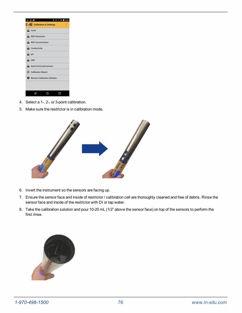
1-970-498-1500 76 www.in-situ.com
4. Select a 1-, 2-, or 3-point calibration.
5. Make sure the restrictor is in calibrationmode.
6. Invert the instrument so the sensors are facing up.
7. Ensure the sensor face and inside of restrictor / calibration cell are thoroughly cleaned and free of debris. Rinse thesensor face and inside of the restrictor with DI or tap water.
8. Take the calibration solution and pour 10-20mL (1/2” above the sensor face) on top of the sensors to perform thefirst rinse.
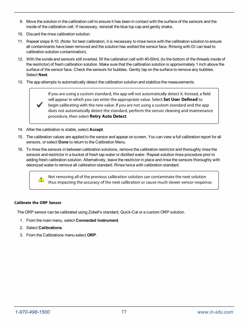
1-970-498-1500 77 www.in-situ.com
9. Move the solution in the calibration cell to ensure it has been in contact with the surface of the sensors and theinside of the calibration cell. If necessary, reinstall the blue top cap and gently shake.
10. Discard the rinse calibration solution.
11. Repeat steps 8-10. (Note: for best calibration, it is necessary to rinse twice with the calibration solution to ensureall contaminants have been removed and the solution has wetted the sensor face. Rinsing with DI can lead tocalibration solution contamination).
12. With the sonde and sensors still inverted, fill the calibration cell with 40-50mL (to the bottom of the threads inside ofthe restrictor) of fresh calibration solution. Make sure that the calibration solution is approximately 1 inch above thesurface of the sensor face. Check the sensors for bubbles. Gently tap on the surface to remove any bubbles.Select Next.
13. The app attempts to automatically detect the calibration solution and stabilize themeasurements.
If you are using a custom standard, the app will not automatically detect it. Instead, a fieldwill appear in which you can enter the appropriate value. Select Set User Defined tobegin calibrating with the new value. If you are not using a custom standard and the appdoes not automatically detect the standard, perform the sensor cleaning and maintenanceprocedure, then select Retry Auto Detect.
14. After the calibration is stable, select Accept.
15. The calibration values are applied to the sensor and appear on screen. You can view a full calibration report for allsensors, or select Done to return to the CalibrationMenu.
16. To rinse the sensors in between calibration solutions, remove the calibration restrictor and thoroughly rinse thesensors and restrictor in a bucket of fresh tap water or distilled water. Repeat solution rinse procedure prior toadding fresh calibration solution. Alternatively, leave the restrictor in place and rinse the sensors thoroughly withdeionized water to remove all calibration standard. Rinse twice with calibration standard.
Not removing all of the previous calibration solution can contaminate the next solutionthus impacting the accuracy of the next calibration or cause much slower sensor response.
Calibrate the ORP Sensor
TheORP sensor can be calibrated using Zobell's standard, Quick-Cal or a custom ORP solution.
1. From themainmenu, select Connected Instrument.
2. Select Calibrations.
3. From the Calibrations menu select ORP.
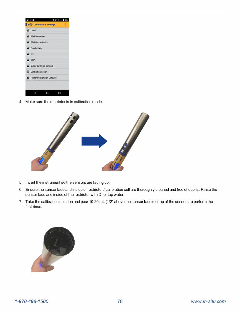
1-970-498-1500 78 www.in-situ.com
4. Make sure the restrictor is in calibrationmode.
5. Invert the instrument so the sensors are facing up.
6. Ensure the sensor face and inside of restrictor / calibration cell are thoroughly cleaned and free of debris. Rinse thesensor face and inside of the restrictor with DI or tap water.
7. Take the calibration solution and pour 10-20mL (1/2” above the sensor face) on top of the sensors to perform thefirst rinse.
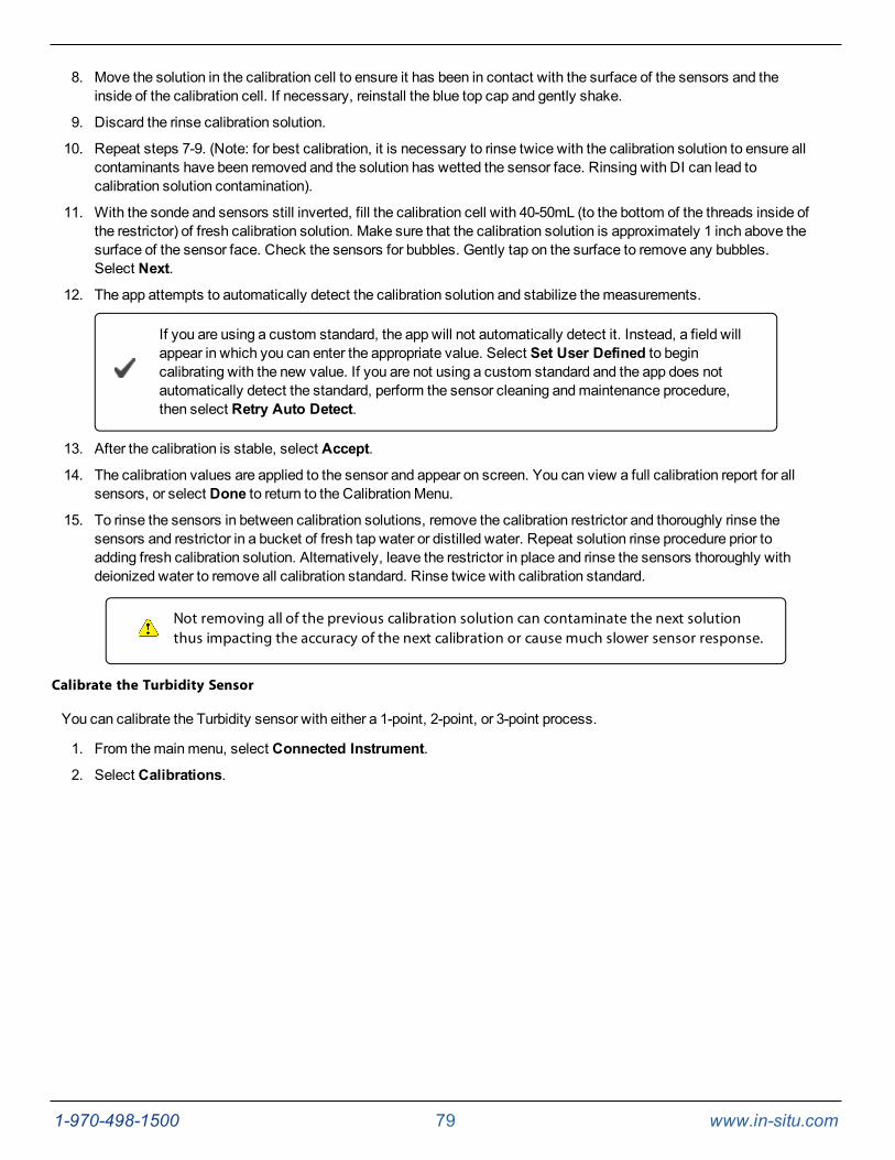
1-970-498-1500 79 www.in-situ.com
8. Move the solution in the calibration cell to ensure it has been in contact with the surface of the sensors and theinside of the calibration cell. If necessary, reinstall the blue top cap and gently shake.
9. Discard the rinse calibration solution.
10. Repeat steps 7-9. (Note: for best calibration, it is necessary to rinse twice with the calibration solution to ensure allcontaminants have been removed and the solution has wetted the sensor face. Rinsing with DI can lead tocalibration solution contamination).
11. With the sonde and sensors still inverted, fill the calibration cell with 40-50mL (to the bottom of the threads inside ofthe restrictor) of fresh calibration solution. Make sure that the calibration solution is approximately 1 inch above thesurface of the sensor face. Check the sensors for bubbles. Gently tap on the surface to remove any bubbles.Select Next.
12. The app attempts to automatically detect the calibration solution and stabilize themeasurements.
If you are using a custom standard, the app will not automatically detect it. Instead, a field willappear in which you can enter the appropriate value. Select Set User Defined to begincalibrating with the new value. If you are not using a custom standard and the app does notautomatically detect the standard, perform the sensor cleaning andmaintenance procedure,then select Retry Auto Detect.
13. After the calibration is stable, select Accept.
14. The calibration values are applied to the sensor and appear on screen. You can view a full calibration report for allsensors, or select Done to return to the CalibrationMenu.
15. To rinse the sensors in between calibration solutions, remove the calibration restrictor and thoroughly rinse thesensors and restrictor in a bucket of fresh tap water or distilled water. Repeat solution rinse procedure prior toadding fresh calibration solution. Alternatively, leave the restrictor in place and rinse the sensors thoroughly withdeionized water to remove all calibration standard. Rinse twice with calibration standard.
Not removing all of the previous calibration solution can contaminate the next solutionthus impacting the accuracy of the next calibration or cause much slower sensor response.
Calibrate the Turbidity Sensor
You can calibrate the Turbidity sensor with either a 1-point, 2-point, or 3-point process.
1. From themainmenu, select Connected Instrument.
2. Select Calibrations.
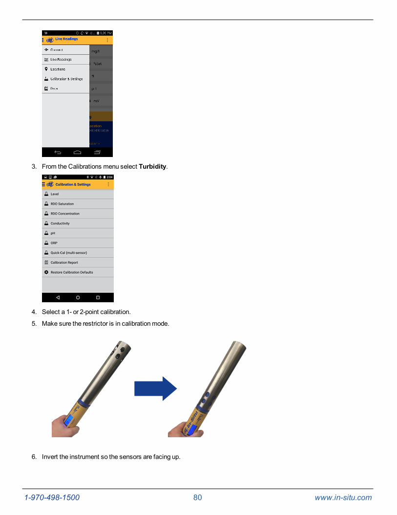
1-970-498-1500 80 www.in-situ.com
3. From the Calibrations menu select Turbidity.
4. Select a 1- or 2-point calibration.
5. Make sure the restrictor is in calibrationmode.
6. Invert the instrument so the sensors are facing up.
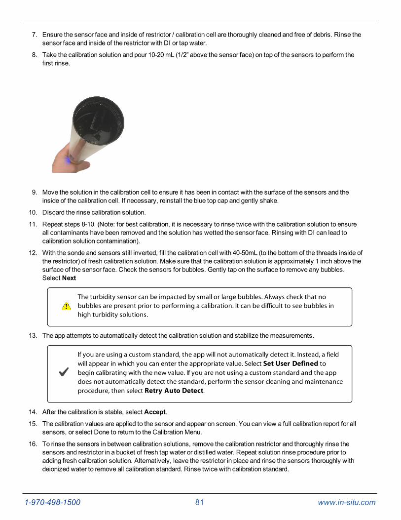
1-970-498-1500 81 www.in-situ.com
7. Ensure the sensor face and inside of restrictor / calibration cell are thoroughly cleaned and free of debris. Rinse thesensor face and inside of the restrictor with DI or tap water.
8. Take the calibration solution and pour 10-20mL (1/2” above the sensor face) on top of the sensors to perform thefirst rinse.
9. Move the solution in the calibration cell to ensure it has been in contact with the surface of the sensors and theinside of the calibration cell. If necessary, reinstall the blue top cap and gently shake.
10. Discard the rinse calibration solution.
11. Repeat steps 8-10. (Note: for best calibration, it is necessary to rinse twice with the calibration solution to ensureall contaminants have been removed and the solution has wetted the sensor face. Rinsing with DI can lead tocalibration solution contamination).
12. With the sonde and sensors still inverted, fill the calibration cell with 40-50mL (to the bottom of the threads inside ofthe restrictor) of fresh calibration solution. Make sure that the calibration solution is approximately 1 inch above thesurface of the sensor face. Check the sensors for bubbles. Gently tap on the surface to remove any bubbles.Select Next
The turbidity sensor can be impacted by small or large bubbles. Always check that nobubbles are present prior to performing a calibration. It can be difficult to see bubbles inhigh turbidity solutions.
13. The app attempts to automatically detect the calibration solution and stabilize themeasurements.
If you are using a custom standard, the app will not automatically detect it. Instead, a fieldwill appear in which you can enter the appropriate value. Select Set User Defined tobegin calibrating with the new value. If you are not using a custom standard and the appdoes not automatically detect the standard, perform the sensor cleaning and maintenanceprocedure, then select Retry Auto Detect.
14. After the calibration is stable, select Accept.
15. The calibration values are applied to the sensor and appear on screen. You can view a full calibration report for allsensors, or select Done to return to the CalibrationMenu.
16. To rinse the sensors in between calibration solutions, remove the calibration restrictor and thoroughly rinse thesensors and restrictor in a bucket of fresh tap water or distilled water. Repeat solution rinse procedure prior toadding fresh calibration solution. Alternatively, leave the restrictor in place and rinse the sensors thoroughly withdeionized water to remove all calibration standard. Rinse twice with calibration standard.
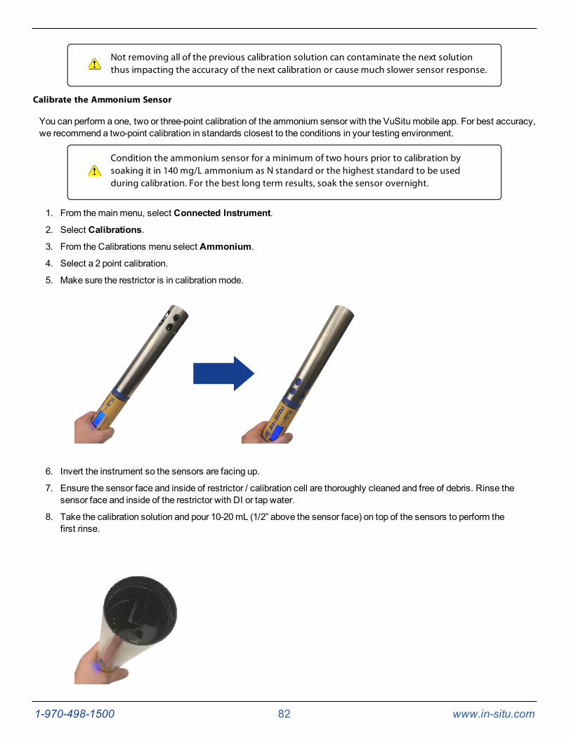
1-970-498-1500 82 www.in-situ.com
Not removing all of the previous calibration solution can contaminate the next solutionthus impacting the accuracy of the next calibration or cause much slower sensor response.
Calibrate the Ammonium Sensor
You can perform a one, two or three-point calibration of the ammonium sensor with the VuSitu mobile app. For best accuracy,we recommend a two-point calibration in standards closest to the conditions in your testing environment.
Condition the ammonium sensor for a minimum of two hours prior to calibration bysoaking it in 140 mg/L ammonium as N standard or the highest standard to be usedduring calibration. For the best long term results, soak the sensor overnight.
1. From themainmenu, select Connected Instrument.
2. Select Calibrations.
3. From the Calibrations menu select Ammonium.
4. Select a 2 point calibration.
5. Make sure the restrictor is in calibrationmode.
6. Invert the instrument so the sensors are facing up.
7. Ensure the sensor face and inside of restrictor / calibration cell are thoroughly cleaned and free of debris. Rinse thesensor face and inside of the restrictor with DI or tap water.
8. Take the calibration solution and pour 10-20mL (1/2” above the sensor face) on top of the sensors to perform thefirst rinse.
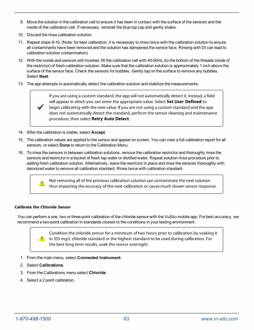
1-970-498-1500 83 www.in-situ.com
9. Move the solution in the calibration cell to ensure it has been in contact with the surface of the sensors and theinside of the calibration cell. If necessary, reinstall the blue top cap and gently shake.
10. Discard the rinse calibration solution.
11. Repeat steps 8-10. (Note: for best calibration, it is necessary to rinse twice with the calibration solution to ensureall contaminants have been removed and the solution has dampened the sensor face. Rinsing with DI can lead tocalibration solution contamination).
12. With the sonde and sensors still inverted, fill the calibration cell with 40-50mL (to the bottom of the threads inside ofthe restrictor) of fresh calibration solution. Make sure that the calibration solution is approximately 1 inch above thesurface of the sensor face. Check the sensors for bubbles. Gently tap on the surface to remove any bubbles.Select Next.
13. The app attempts to automatically detect the calibration solution and stabilize themeasurements.
If you are using a custom standard, the app will not automatically detect it. Instead, a fieldwill appear in which you can enter the appropriate value. Select Set User Defined tobegin calibrating with the new value. If you are not using a custom standard and the appdoes not automatically detect the standard, perform the sensor cleaning and maintenanceprocedure, then select Retry Auto Detect.
14. After the calibration is stable, select Accept.
15. The calibration values are applied to the sensor and appear on screen. You can view a full calibration report for allsensors, or select Done to return to the CalibrationMenu.
16. To rinse the sensors in between calibration solutions, remove the calibration restrictor and thoroughly rinse thesensors and restrictor in a bucket of fresh tap water or distilled water. Repeat solution rinse procedure prior toadding fresh calibration solution. Alternatively, leave the restrictor in place and rinse the sensors thoroughly withdeionized water to remove all calibration standard. Rinse twice with calibration standard.
Not removing all of the previous calibration solution can contaminate the next solutionthus impacting the accuracy of the next calibration or cause much slower sensor response.
Calibrate the Chloride Sensor
You can perform a one, two or three-point calibration of the chloride sensor with the VuSitu mobile app. For best accuracy, werecommend a two-point calibration in standards closest to the conditions in your testing environment.
Condition the chloride sensor for a minimum of two hours prior to calibration by soaking itin 355 mg/L chloride standard or the highest standard to be used during calibration. Forthe best long term results, soak the sensor overnight.
1. From themainmenu, select Connected Instrument.
2. Select Calibrations.
3. From the Calibrations menu select Chloride.
4. Select a 2 point calibration.
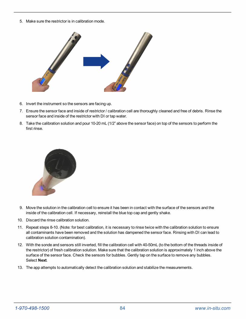
1-970-498-1500 84 www.in-situ.com
5. Make sure the restrictor is in calibrationmode.
6. Invert the instrument so the sensors are facing up.
7. Ensure the sensor face and inside of restrictor / calibration cell are thoroughly cleaned and free of debris. Rinse thesensor face and inside of the restrictor with DI or tap water.
8. Take the calibration solution and pour 10-20mL (1/2” above the sensor face) on top of the sensors to perform thefirst rinse.
9. Move the solution in the calibration cell to ensure it has been in contact with the surface of the sensors and theinside of the calibration cell. If necessary, reinstall the blue top cap and gently shake.
10. Discard the rinse calibration solution.
11. Repeat steps 8-10. (Note: for best calibration, it is necessary to rinse twice with the calibration solution to ensureall contaminants have been removed and the solution has dampened the sensor face. Rinsing with DI can lead tocalibration solution contamination).
12. With the sonde and sensors still inverted, fill the calibration cell with 40-50mL (to the bottom of the threads inside ofthe restrictor) of fresh calibration solution. Make sure that the calibration solution is approximately 1 inch above thesurface of the sensor face. Check the sensors for bubbles. Gently tap on the surface to remove any bubbles.Select Next.
13. The app attempts to automatically detect the calibration solution and stabilize themeasurements.
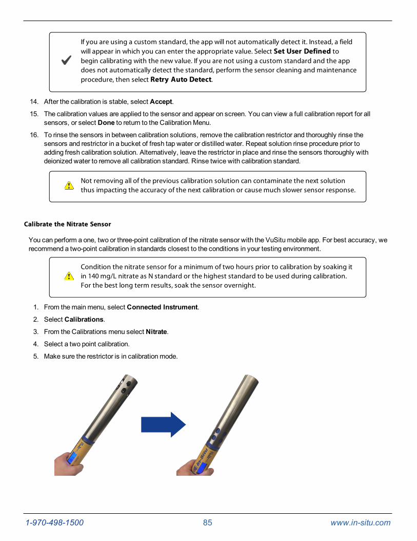
1-970-498-1500 85 www.in-situ.com
If you are using a custom standard, the app will not automatically detect it. Instead, a fieldwill appear in which you can enter the appropriate value. Select Set User Defined tobegin calibrating with the new value. If you are not using a custom standard and the appdoes not automatically detect the standard, perform the sensor cleaning and maintenanceprocedure, then select Retry Auto Detect.
14. After the calibration is stable, select Accept.
15. The calibration values are applied to the sensor and appear on screen. You can view a full calibration report for allsensors, or select Done to return to the CalibrationMenu.
16. To rinse the sensors in between calibration solutions, remove the calibration restrictor and thoroughly rinse thesensors and restrictor in a bucket of fresh tap water or distilled water. Repeat solution rinse procedure prior toadding fresh calibration solution. Alternatively, leave the restrictor in place and rinse the sensors thoroughly withdeionized water to remove all calibration standard. Rinse twice with calibration standard.
Not removing all of the previous calibration solution can contaminate the next solutionthus impacting the accuracy of the next calibration or cause much slower sensor response.
Calibrate the Nitrate Sensor
You can perform a one, two or three-point calibration of the nitrate sensor with the VuSitu mobile app. For best accuracy, werecommend a two-point calibration in standards closest to the conditions in your testing environment.
Condition the nitrate sensor for a minimum of two hours prior to calibration by soaking itin 140 mg/L nitrate as N standard or the highest standard to be used during calibration.For the best long term results, soak the sensor overnight.
1. From themainmenu, select Connected Instrument.
2. Select Calibrations.
3. From the Calibrations menu select Nitrate.
4. Select a two point calibration.
5. Make sure the restrictor is in calibrationmode.
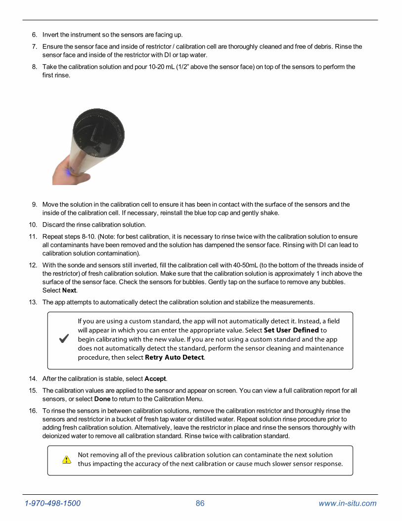
1-970-498-1500 86 www.in-situ.com
6. Invert the instrument so the sensors are facing up.
7. Ensure the sensor face and inside of restrictor / calibration cell are thoroughly cleaned and free of debris. Rinse thesensor face and inside of the restrictor with DI or tap water.
8. Take the calibration solution and pour 10-20mL (1/2” above the sensor face) on top of the sensors to perform thefirst rinse.
9. Move the solution in the calibration cell to ensure it has been in contact with the surface of the sensors and theinside of the calibration cell. If necessary, reinstall the blue top cap and gently shake.
10. Discard the rinse calibration solution.
11. Repeat steps 8-10. (Note: for best calibration, it is necessary to rinse twice with the calibration solution to ensureall contaminants have been removed and the solution has dampened the sensor face. Rinsing with DI can lead tocalibration solution contamination).
12. With the sonde and sensors still inverted, fill the calibration cell with 40-50mL (to the bottom of the threads inside ofthe restrictor) of fresh calibration solution. Make sure that the calibration solution is approximately 1 inch above thesurface of the sensor face. Check the sensors for bubbles. Gently tap on the surface to remove any bubbles.Select Next.
13. The app attempts to automatically detect the calibration solution and stabilize themeasurements.
If you are using a custom standard, the app will not automatically detect it. Instead, a fieldwill appear in which you can enter the appropriate value. Select Set User Defined tobegin calibrating with the new value. If you are not using a custom standard and the appdoes not automatically detect the standard, perform the sensor cleaning and maintenanceprocedure, then select Retry Auto Detect.
14. After the calibration is stable, select Accept.
15. The calibration values are applied to the sensor and appear on screen. You can view a full calibration report for allsensors, or select Done to return to the CalibrationMenu.
16. To rinse the sensors in between calibration solutions, remove the calibration restrictor and thoroughly rinse thesensors and restrictor in a bucket of fresh tap water or distilled water. Repeat solution rinse procedure prior toadding fresh calibration solution. Alternatively, leave the restrictor in place and rinse the sensors thoroughly withdeionized water to remove all calibration standard. Rinse twice with calibration standard.
Not removing all of the previous calibration solution can contaminate the next solutionthus impacting the accuracy of the next calibration or cause much slower sensor response.
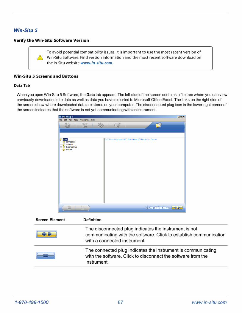
1-970-498-1500 87 www.in-situ.com
Win-Situ 5
Verify the Win-Situ Software Version
To avoid potential compatibility issues, it is important to use the most recent version ofWin-Situ Software. Find version information and the most recent software download onthe In-Situ website www.in-situ.com.
Win-Situ 5 Screens and Buttons
Data Tab
When you openWin-Situ 5 Software, theData tab appears. The left side of the screen contains a file tree where you can viewpreviously downloaded site data as well as data you have exported toMicrosoft Office Excel. The links on the right side ofthe screen show where downloaded data are stored on your computer. The disconnected plug icon in the lower-right corner ofthe screen indicates that the software is not yet communicating with an instrument.
Screen Element Definition
The disconnected plug indicates the instrument is notcommunicating with the software. Click to establish communicationwith a connected instrument.
The connected plug indicates the instrument is communicatingwith the software. Click to disconnect the software from theinstrument.
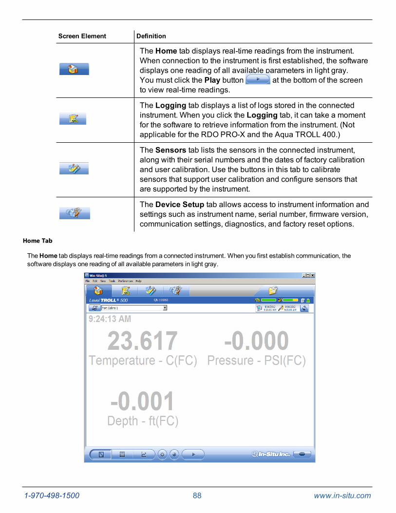
1-970-498-1500 88 www.in-situ.com
Screen Element Definition
The Home tab displays real-time readings from the instrument.When connection to the instrument is first established, the softwaredisplays one reading of all available parameters in light gray.You must click the Play button at the bottom of the screento view real-time readings.
The Logging tab displays a list of logs stored in the connectedinstrument. When you click the Logging tab, it can take a momentfor the software to retrieve information from the instrument. (Notapplicable for the RDO PRO-X and the Aqua TROLL 400.)
The Sensors tab lists the sensors in the connected instrument,along with their serial numbers and the dates of factory calibrationand user calibration. Use the buttons in this tab to calibratesensors that support user calibration and configure sensors thatare supported by the instrument.
The Device Setup tab allows access to instrument information andsettings such as instrument name, serial number, firmware version,communication settings, diagnostics, and factory reset options.
Home Tab
TheHome tab displays real-time readings from a connected instrument. When you first establish communication, thesoftware displays one reading of all available parameters in light gray.
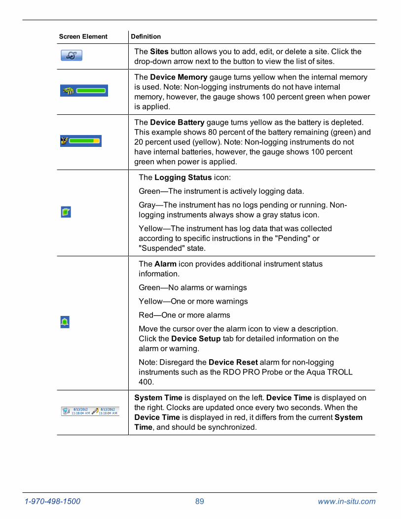
1-970-498-1500 89 www.in-situ.com
Screen Element Definition
The Sites button allows you to add, edit, or delete a site. Click thedrop-down arrow next to the button to view the list of sites.
The Device Memory gauge turns yellow when the internal memoryis used. Note: Non-logging instruments do not have internalmemory, however, the gauge shows 100 percent green when poweris applied.
The Device Battery gauge turns yellow as the battery is depleted.This example shows 80 percent of the battery remaining (green) and20 percent used (yellow). Note: Non-logging instruments do nothave internal batteries, however, the gauge shows 100 percentgreen when power is applied.
The Logging Status icon:Green—The instrument is actively logging data.
Gray—The instrument has no logs pending or running. Non-logging instruments always show a gray status icon.
Yellow—The instrument has log data that was collectedaccording to specific instructions in the "Pending" or"Suspended" state.
The Alarm icon provides additional instrument statusinformation.
Green—No alarms or warnings
Yellow—One or more warnings
Red—One or more alarms
Move the cursor over the alarm icon to view a description.Click the Device Setup tab for detailed information on thealarm or warning.
Note: Disregard the Device Reset alarm for non-logginginstruments such as the RDO PRO Probe or the Aqua TROLL400.
System Time is displayed on the left. Device Time is displayed onthe right. Clocks are updated once every two seconds. When theDevice Time is displayed in red, it differs from the current SystemTime, and should be synchronized.
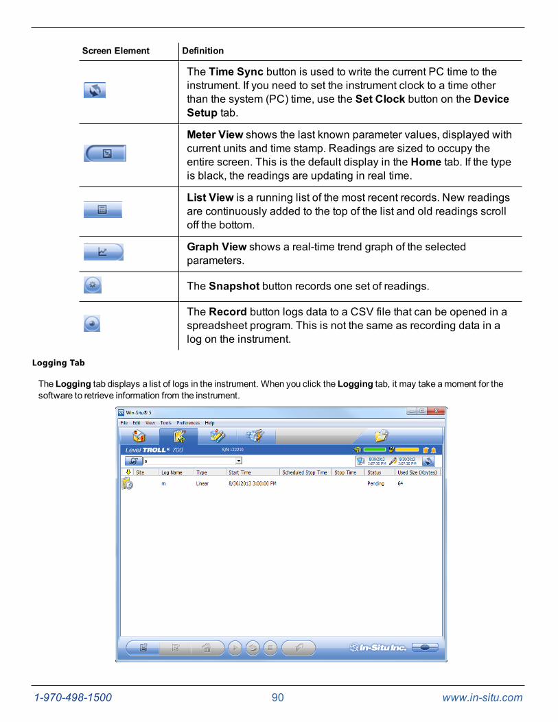
1-970-498-1500 90 www.in-situ.com
Screen Element Definition
The Time Sync button is used to write the current PC time to theinstrument. If you need to set the instrument clock to a time otherthan the system (PC) time, use the Set Clock button on the DeviceSetup tab.
Meter View shows the last known parameter values, displayed withcurrent units and time stamp. Readings are sized to occupy theentire screen. This is the default display in the Home tab. If the typeis black, the readings are updating in real time.
List View is a running list of the most recent records. New readingsare continuously added to the top of the list and old readings scrolloff the bottom.
Graph View shows a real-time trend graph of the selectedparameters.
The Snapshot button records one set of readings.
The Record button logs data to a CSV file that can be opened in aspreadsheet program. This is not the same as recording data in alog on the instrument.
Logging Tab
The Logging tab displays a list of logs in the instrument. When you click the Logging tab, it may take amoment for thesoftware to retrieve information from the instrument.
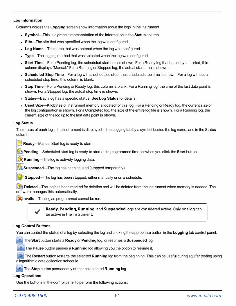
1-970-498-1500 91 www.in-situ.com
Log InformationColumns across the Logging screen show information about the logs in the instrument.
l Symbol—This is a graphic representation of the information in theStatus column.
l Site—The site that was specified when the log was configured.
l Log Name—The name that was entered when the log was configured.
l Type—The loggingmethod that was selected when the log was configured.
l Start Time—For a Pending log, the scheduled start time is shown. For a Ready log that has not yet started, thiscolumn displays “Manual.” For a Running or Stopped log, the actual start time is shown.
l Scheduled Stop Time—For a log with a scheduled stop, the scheduled stop time is shown. For a log without ascheduled stop time, this column is blank.
l Stop Time—For a Pending or Ready log, this column is blank. For a Running log, the time of the last data point isshown. For a Stopped log, the actual stop time is shown.
l Status—Each log has a specific status. See Log Status for details.
l Used Size—Kilobytes of instrument memory allocated for this log. For a Pending or Ready log, the current size ofthe log configuration is shown. For a Completed log, the size of the entire log file is shown. For a Running log, thecurrent size of the log up to the last data point is shown.
Log StatusThe status of each log in the instrument is displayed in the Logging tab by a symbol beside the log name, and in the Statuscolumn.
Ready—Manual Start log is ready to start.
Pending—Scheduled start log is ready to start at its programmed time, or when you click theStart button.
Running—The log is actively logging data.
Suspended—The log has been paused (stopped temporarily).
Stopped—The log has been stopped, either manually or on a schedule.
Deleted—The log has beenmarked for deletion and will be deleted from the instrument whenmemory is needed. Thesoftwaremanages this automatically.
Invalid—The log as programmed cannot be run.
Ready, Pending, Running, and Suspended logs are considered active. Only one log canbe active in the instrument.
Log Control ButtonsYou can control the status of a log by selecting the log and clicking the appropriate button in the Logging tab control panel:
TheStart button starts aReady orPending log, or resumes aSuspended log.
ThePause button pauses aRunning log allowing you the option to resume it.
TheRestart button restarts the selectedRunning log from the beginning. This can be useful during aquifer testing usinga logarithmic data collection schedule.
TheStop button permanently stops the selectedRunning log.
Log OperationsUse the buttons in the control panel to perform the following actions:
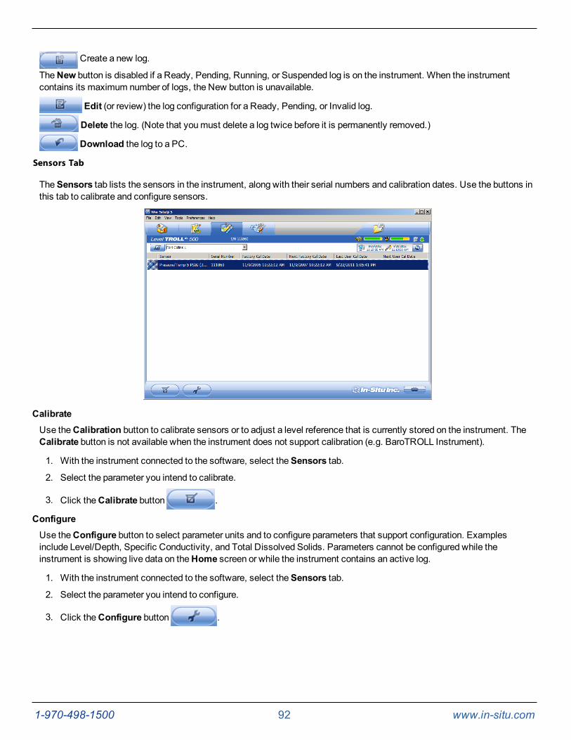
1-970-498-1500 92 www.in-situ.com
Create a new log.
TheNew button is disabled if a Ready, Pending, Running, or Suspended log is on the instrument. When the instrumentcontains its maximum number of logs, the New button is unavailable.
Edit (or review) the log configuration for a Ready, Pending, or Invalid log.
Delete the log. (Note that youmust delete a log twice before it is permanently removed.)
Download the log to a PC.
Sensors Tab
TheSensors tab lists the sensors in the instrument, along with their serial numbers and calibration dates. Use the buttons inthis tab to calibrate and configure sensors.
CalibrateUse theCalibration button to calibrate sensors or to adjust a level reference that is currently stored on the instrument. TheCalibrate button is not available when the instrument does not support calibration (e.g. BaroTROLL Instrument).
1. With the instrument connected to the software, select theSensors tab.
2. Select the parameter you intend to calibrate.
3. Click theCalibrate button .
ConfigureUse theConfigure button to select parameter units and to configure parameters that support configuration. Examplesinclude Level/Depth, Specific Conductivity, and Total Dissolved Solids. Parameters cannot be configured while theinstrument is showing live data on theHome screen or while the instrument contains an active log.
1. With the instrument connected to the software, select theSensors tab.
2. Select the parameter you intend to configure.
3. Click theConfigure button .
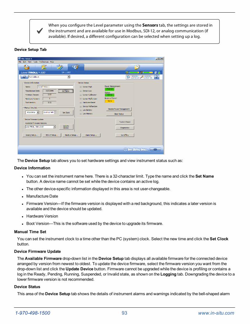
1-970-498-1500 93 www.in-situ.com
When you configure the Level parameter using the Sensors tab, the settings are stored inthe instrument and are available for use in Modbus, SDI-12, or analog communication (ifavailable). If desired, a different configuration can be selected when setting up a log.
Device Setup Tab
TheDevice Setup tab allows you to set hardware settings and view instrument status such as:
Device Information
l You can set the instrument name here. There is a 32-character limit. Type the name and click theSet Namebutton. A device name cannot be set while the device contains an active log.
l The other device-specific information displayed in this area is not user-changeable.
l Manufacture Date
l Firmware Version—If the firmware version is displayed with a red background, this indicates a later version isavailable and the device should be updated.
l Hardware Version
l Boot Version—This is the software used by the device to upgrade its firmware.
Manual Time SetYou can set the instrument clock to a time other than the PC (system) clock. Select the new time and click theSet Clockbutton.
Device Firmware UpdateTheAvailable Firmware drop-down list in theDevice Setup tab displays all available firmware for the connected devicearranged by version from newest to oldest. To update the device firmware, select the firmware version you want from thedrop-down list and click theUpdate Device button. Firmware cannot be upgraded while the device is profiling or contains alog in the Ready, Pending, Running, Suspended, or Invalid state, as shown on the Logging tab. Downgrading the device to alower firmware version is not recommended.
Device StatusThis area of theDevice Setup tab shows the details of instrument alarms and warnings indicated by the bell-shaped alarm
1-970-498-1500 94 www.in-situ.com
icon.
Status colors:
Gray—No alarms or warnings
Yellow—Warning
Red—Alarm
l Sensor High: An alarm or warning when values reported by a sensor have exceeded a user-set "high" alarm orwarning threshold.
l Sensor Low: An alarm or warning when values reported by a sensor have dropped below a user-set "low" alarm orwarning threshold.
l Sensor Calibration: A warning when factory calibration expires or when a user calibration date has passed.
l Sensor Malfunction: This alarm lights when a water-quality sensor malfunctions.
l Hardware Reset: This warning indicates that the device has reset itself following a serious interruption, such as alightning strike. If the device clock is lost during logging, the log will resumewhen the device recovers from thereset, at whatever time is then active in the device. Disregard this warning for non-logging instruments.
l DeviceMalfunction: An alarm is activated when the device has malfunctioned. Call Technical Support.
l Low Battery: An alarm is activated when 5 percent of the device battery capacity remains.
l Low Memory: An alarm is activated when 5 percent of the devicememory capacity remains.
Buttons in this area of theDevice Setup tab are used to set up alarms, clear alarms, and take the device offline. To clear analarm indicator, click theClear Status button.
Factory ResetTo restore factory settings in the device (less any firmware upgrades), click the Factory Reset button in theDevice Setuptab.
A factory reset removes all logged data from the device. This button is not available if the device is profiling or contains anactive log.
Analog SetupTo configure the device for 4-20mA output, click theAnalog Setup... button in theDevice Setup tab. Analog is notsupported on all instruments.
SDI-12 SetupTo configure the SDI-12 output from the device, click theSDI-12 Setup... button in theDevice Setup tab.
Alarm SetupTo configure the instrument alarm and/or warning indicators, click theAlarm Setup... button in theDevice Setup tab.
Modbus SetupThese settings permit devices on a network and devices connected via a gateway such as amodem or TCP/IP to bechanged independent of the connection link. To configure the device communication settings, click theModbus Setup...button in theDevice Setup tab.
Win-Situ 5 Logging and Viewing Data
About Sites
All data logged by In-Situ instruments are tied to a specific site. A site represents the physical location where the instrumentcollects data. For example, you can create a site to represent a lake, gauging station, well, or nearby landmark.
You are prompted to select a site when you set up a data log. A default site is loaded with the software, and can be used, butit does not provide any specific information about the place where the data was collected.
1-970-498-1500 95 www.in-situ.com
l When you set up a new site, aSite folder with the same name is created in the folder tree on theData tab. Site
folders are designated by this icon .
l When you set up a data log, the first thing you are asked to supply is a site.
l When you download a data log, it appears in its Site folder in the folder tree on the first screen Data tab. See page87. This provides a convenient way to organize data collected from the same instrument at different locations, orfrom different instruments at a common location.
Sites are stored in a database on your computer in yourWin-Situ working directory. More information. After a new site isadded, it is available to select for any instrument and any log.
Only one site at a time is programmed in the instrument and it is shown in the Site box at the top of the screen.
For additional information see:
Adding a New Site
Managing Sites
Logging Data—Overview
Win-Situ provides many ways to customize the collection of field data.
l Schedule the instrument to start and stop a log at a specified time.
l Set up a log and start it manually. While the instrument is connected to the software, you can watch the first fewreadings in tabular or graphical form. Disconnect from the software and let the instrument collect data. Manuallyreconnect to the instrument and download the collected data at any time.
l Start a log, check the data, pause the log, reposition the device, restart the log.
l Download data logs to folders on your PC.
What do you want to do?
l Set up a new data log.
l Start a log that has been set up in the instrument.
l View the logs on the instrument.
l Download a log tomy PC.
l Stop a log that is running on the instrument.
l Suspend (temporarily stop) a log that is running in the instrument.
l Delete a log from the instrument.
Logging Method Descriptions
The following is a list of log types and their descriptions. The log types that are available on an instrument vary dependingupon the capabilities of the instrument.
Logging Methods for Long-Term Monitoring
Linear
Linear log typemeasures and records at a user-defined fixed interval of oneminute or more. This method is used for long-termstudies, landfill monitoring, stream gauging, tidal studies, and backgroundmonitoring prior to aquifer testing. Intervals aremeasured in days, hours, or minutes.
Linear Average
Linear Average log type can smooth out anomalous highs and lows that may occur in a data set, for example, when a waterwave passes over the instrument. Each storedmeasurement is the average of several rapid measurements. This method is
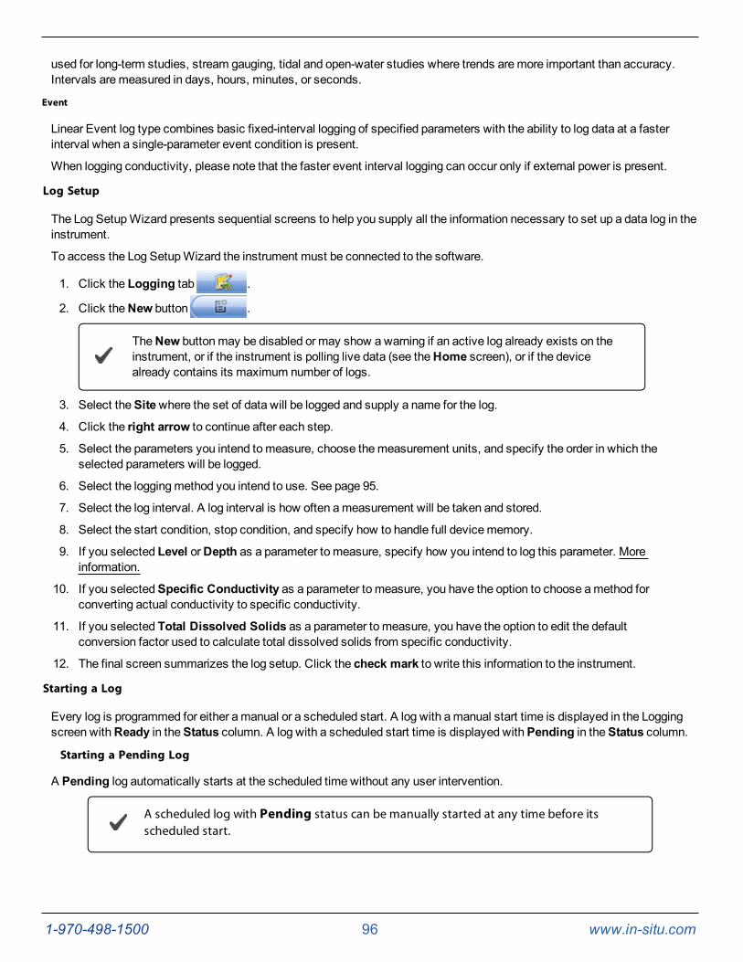
1-970-498-1500 96 www.in-situ.com
used for long-term studies, stream gauging, tidal and open-water studies where trends aremore important than accuracy.Intervals aremeasured in days, hours, minutes, or seconds.
Event
Linear Event log type combines basic fixed-interval logging of specified parameters with the ability to log data at a fasterinterval when a single-parameter event condition is present.
When logging conductivity, please note that the faster event interval logging can occur only if external power is present.
Log Setup
The Log SetupWizard presents sequential screens to help you supply all the information necessary to set up a data log in theinstrument.
To access the Log SetupWizard the instrument must be connected to the software.
1. Click the Logging tab .
2. Click theNew button .
TheNew buttonmay be disabled or may show awarning if an active log already exists on theinstrument, or if the instrument is polling live data (see theHome screen), or if the devicealready contains its maximum number of logs.
3. Select theSitewhere the set of data will be logged and supply a name for the log.
4. Click the right arrow to continue after each step.
5. Select the parameters you intend tomeasure, choose themeasurement units, and specify the order in which theselected parameters will be logged.
6. Select the loggingmethod you intend to use. See page 95.
7. Select the log interval. A log interval is how often ameasurement will be taken and stored.
8. Select the start condition, stop condition, and specify how to handle full devicememory.
9. If you selected Level orDepth as a parameter to measure, specify how you intend to log this parameter. Moreinformation.
10. If you selectedSpecific Conductivity as a parameter to measure, you have the option to choose amethod forconverting actual conductivity to specific conductivity.
11. If you selected Total Dissolved Solids as a parameter to measure, you have the option to edit the defaultconversion factor used to calculate total dissolved solids from specific conductivity.
12. The final screen summarizes the log setup. Click the check mark to write this information to the instrument.
Starting a Log
Every log is programmed for either amanual or a scheduled start. A log with amanual start time is displayed in the Loggingscreen withReady in theStatus column. A log with a scheduled start time is displayed withPending in theStatus column.
Starting a Pending Log
A Pending log automatically starts at the scheduled time without any user intervention.
A scheduled log with Pending status can be manually started at any time before itsscheduled start.
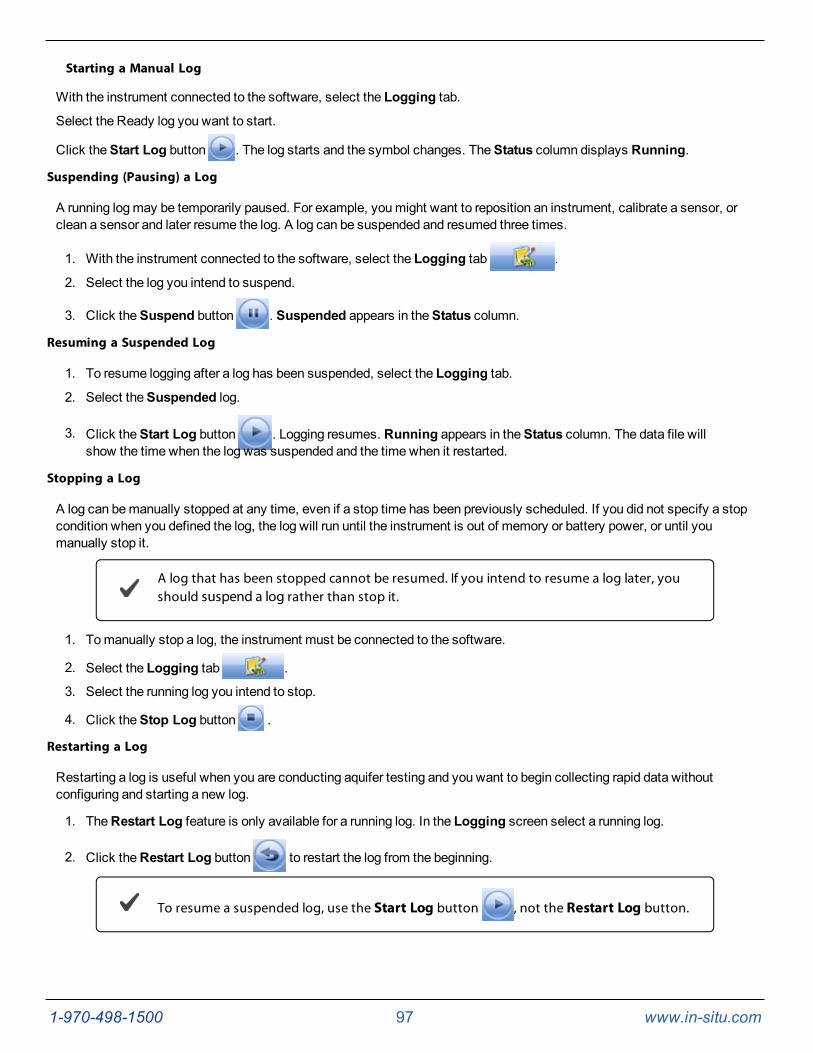
1-970-498-1500 97 www.in-situ.com
Starting a Manual Log
With the instrument connected to the software, select the Logging tab.
Select the Ready log you want to start.
Click theStart Log button . The log starts and the symbol changes. TheStatus column displays Running.
Suspending (Pausing) a Log
A running logmay be temporarily paused. For example, youmight want to reposition an instrument, calibrate a sensor, orclean a sensor and later resume the log. A log can be suspended and resumed three times.
1. With the instrument connected to the software, select the Logging tab .
2. Select the log you intend to suspend.
3. Click theSuspend button . Suspended appears in theStatus column.
Resuming a Suspended Log
1. To resume logging after a log has been suspended, select the Logging tab.
2. Select theSuspended log.
3. Click theStart Log button . Logging resumes. Running appears in theStatus column. The data file willshow the time when the log was suspended and the time when it restarted.
Stopping a Log
A log can bemanually stopped at any time, even if a stop time has been previously scheduled. If you did not specify a stopcondition when you defined the log, the log will run until the instrument is out of memory or battery power, or until youmanually stop it.
A log that has been stopped cannot be resumed. If you intend to resume a log later, youshould suspend a log rather than stop it.
1. Tomanually stop a log, the instrument must be connected to the software.
2. Select the Logging tab .
3. Select the running log you intend to stop.
4. Click theStop Log button .
Restarting a Log
Restarting a log is useful when you are conducting aquifer testing and you want to begin collecting rapid data withoutconfiguring and starting a new log.
1. TheRestart Log feature is only available for a running log. In the Logging screen select a running log.
2. Click theRestart Log button to restart the log from the beginning.
To resume a suspended log, use the Start Log button , not the Restart Log button.
1-970-498-1500 98 www.in-situ.com
Downloading Data to a PC
This procedure copies the data log from the instrument to a PC. It does not remove the data log from the instrument. After alog is downloaded, it can be exported to a CSV file format that can be used by spreadsheet programs. The time shown in thelog name is the time the log was downloaded.
1. With an instrument connected, select the Logging tab .
2. Select the log you intend to download.
3. Choose a Running, Suspended, Stopped, or Deleted log.
4. Click theDownload button.
5. In the next screen, select one of the three download options.
l All data
l New data (data logged since the last download)
l Time interval to download
New data is downloaded by default to a new log file. To append new data to the last download ofthis log, be sure the option "Append logs on download" is selected in theGeneral Settingsdialog (Preferences > General Settings).
2. The log is copied to the connected PC into yourWin-Situ working directory folder. View or change the workingdirectory using File > Settings.
3. At the end of the download, Win-Situ gives you the option of viewing the data.
l Select Yes and the log is displayed in theData screen.
l Select No and the Logging screen appears. You can view the data at any time by selecting it in theDatatab.
Viewing Logged Data
1. To view the data stored in the instrument, youmust first download the data. A connection to an instrument is notneeded after the data log has been downloaded.
2. Select theData tab .
3. On the left side of the screen, select the log you want to view. To expand a folder shown in the navigation tree,double-click the folder. The content of the data log is displayed on the right side of the screen in text or graphformat.
To switch between view formats, click the Text or the Graph button in the control panel.To customize the text or graph view, select Preferences >Graph Settings orPreferences >Data View Settings. These options apply to all downloaded data untilyou change the options.
1-970-498-1500 99 www.in-situ.com
Exporting Data
Exporting Data to Spreadsheet Format
1. Download the log from the instrument to your PC.
2. Select theData tab .
3. On the left side of the screen, select the log you intend to export. The content of the log is displayed on the rightside of the screen.
To export all of the logs in the site, select the site.
4. Select Filemenu > Export to CSV. The log is exported to theExported Data folder into a sub-folder with thesame name as the data site of the log. If the folder does not yet exist, Win-Situ creates it.
5. To open the CSV file, do one of the following:
l Double-click the exported file in the navigation tree on the left side of theData tab
l Access the file inWindows Explorer and double-click the file (for example: C:\ My Documents \ Win-Situ Data \Exported Data \ my data site \ drawdown test 2006-05-28 11-00-00).
Exporting to Text
To export one or more data logs to text format, follow the steps above, except at step 5 select Filemenu > Export to Text.Double-click the exported file to open it inWindows Notepad or your default text editor.
Graphing Data
Real-time data and downloaded log datamay be viewed in text (default) or graphic form.
View a Graph of a Downloaded File
1. Click theData tab .
2. Select a downloaded log file from the list on the left. Log files are located in the site folders.
3. Click theGraph button .
View a Graph of Real-Time Data
1. With an instrument connected to the software, click theHome tab .
2. Click theStart button .
3. Click theGraph button .
Graph Settings
The initial display uses the default graph settings (Preferencesmenu > Graph Settings) for all graphs. Each log file canhave its own customized graph settings that are saved with the log file.
The defaults are as follows.
l All log channels are shown in the order in which they were logged.
l X axis (time) is across the bottom and is auto-scaled.
l Y axis (values), one for each channel, are stacked along the left side of the graph and are auto-scaled to show thefull range of the data.
Graph Templates
If you have saved any custom graph templates, you can select one with the Load Template button.
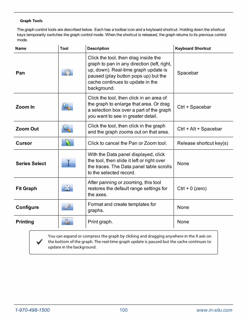
1-970-498-1500 100 www.in-situ.com
Graph Tools
The graph control tools are described below. Each has a toolbar icon and a keyboard shortcut. Holding down the shortcutkeys temporarily switches the graph control mode. When the shortcut is released, the graph returns to its previous controlmode.
Name Tool Description Keyboard Shortcut
Pan
Click the tool, then drag inside thegraph to pan in any direction (left, right,up, down). Real-time graph update ispaused (play button pops up) but thecache continues to update in thebackground.
Spacebar
Zoom In
Click the tool, then click in an area ofthe graph to enlarge that area. Or draga selection box over a part of the graphyou want to see in greater detail.
Ctrl + Spacebar
Zoom Out Click the tool, then click in the graphand the graph zooms out on that area. Ctrl + Alt + Spacebar
Cursor Click to cancel the Pan or Zoom tool. Release shortcut key(s)
Series Select
With the Data panel displayed, clickthe tool, then slide it left or right overthe traces. The Data panel table scrollsto the selected record.
None
Fit GraphAfter panning or zooming, this toolrestores the default range settings forthe axes.
Ctrl + 0 (zero)
Configure Format and create templates forgraphs. None
Printing Print graph. None
You can expand or compress the graph by clicking and dragging anywhere in the X axis onthe bottom of the graph. The real-time graph update is paused but the cache continues toupdate in the background.
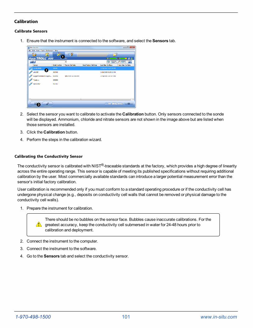
1-970-498-1500 101 www.in-situ.com
Calibration
Calibrate Sensors
1. Ensure that the instrument is connected to the software, and select theSensors tab.
2. Select the sensor you want to calibrate to activate theCalibration button. Only sensors connected to the sondewill be displayed. Ammonium, chloride and nitrate sensors are not shown in the image above but are listed whenthose sensors are installed.
3. Click theCalibration button.
4. Perform the steps in the calibration wizard.
Calibrating the Conductivity Sensor
The conductivity sensor is calibrated with NIST®-traceable standards at the factory, which provides a high degree of linearityacross the entire operating range. This sensor is capable of meeting its published specifications without requiring additionalcalibration by the user. Most commercially available standards can introduce a larger potential measurement error than thesensor’s initial factory calibration.
User calibration is recommended only if youmust conform to a standard operating procedure or if the conductivity cell hasundergone physical change (e.g., deposits on conductivity cell walls that cannot be removed or physical damage to theconductivity cell walls).
1. Prepare the instrument for calibration.
There should be no bubbles on the sensor face. Bubbles cause inaccurate calibrations. For thegreatest accuracy, keep the conductivity cell submersed in water for 24-48 hours prior tocalibration and deployment.
2. Connect the instrument to the computer.
3. Connect the instrument to the software.
4. Go to theSensors tab and select the conductivity sensor.

1-970-498-1500 102 www.in-situ.com
5. Click theCalibrate button .
If you want to restore the factory calibration, select the check box and click the right arrowbutton.
6. Select either 20° C or 25° C as the reference temperature, as indicated by the reference calibration solution.
7. Select the appropriate calibration standard from the drop-down list. If you select “User Defined,” enter the value ofthe solution.
8. Click the right arrow button.
9. Click OK to start the calibration.
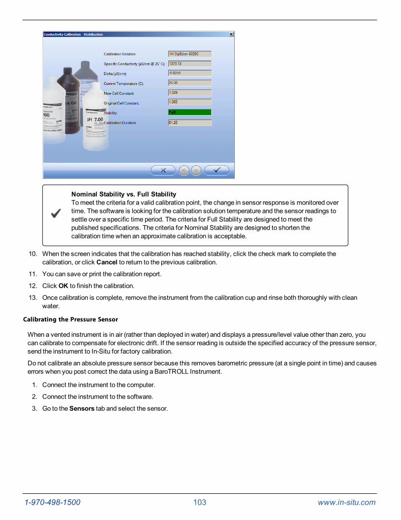
1-970-498-1500 103 www.in-situ.com
Nominal Stability vs. Full StabilityTomeet the criteria for a valid calibration point, the change in sensor response is monitored overtime. The software is looking for the calibration solution temperature and the sensor readings tosettle over a specific time period. The criteria for Full Stability are designed tomeet thepublished specifications. The criteria for Nominal Stability are designed to shorten thecalibration time when an approximate calibration is acceptable.
10. When the screen indicates that the calibration has reached stability, click the check mark to complete thecalibration, or click Cancel to return to the previous calibration.
11. You can save or print the calibration report.
12. Click OK to finish the calibration.
13. Once calibration is complete, remove the instrument from the calibration cup and rinse both thoroughly with cleanwater.
Calibrating the Pressure Sensor
When a vented instrument is in air (rather than deployed in water) and displays a pressure/level value other than zero, youcan calibrate to compensate for electronic drift. If the sensor reading is outside the specified accuracy of the pressure sensor,send the instrument to In-Situ for factory calibration.
Do not calibrate an absolute pressure sensor because this removes barometric pressure (at a single point in time) and causeserrors when you post correct the data using a BaroTROLL Instrument.
1. Connect the instrument to the computer.
2. Connect the instrument to the software.
3. Go to theSensors tab and select the sensor.
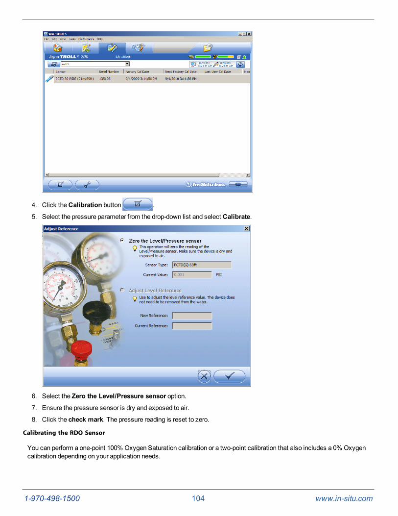
1-970-498-1500 104 www.in-situ.com
4. Click theCalibration button .
5. Select the pressure parameter from the drop-down list and select Calibrate.
6. Select the Zero the Level/Pressure sensor option.
7. Ensure the pressure sensor is dry and exposed to air.
8. Click the check mark. The pressure reading is reset to zero.
Calibrating the RDO Sensor
You can perform a one-point 100% Oxygen Saturation calibration or a two-point calibration that also includes a 0% Oxygencalibration depending on your application needs.
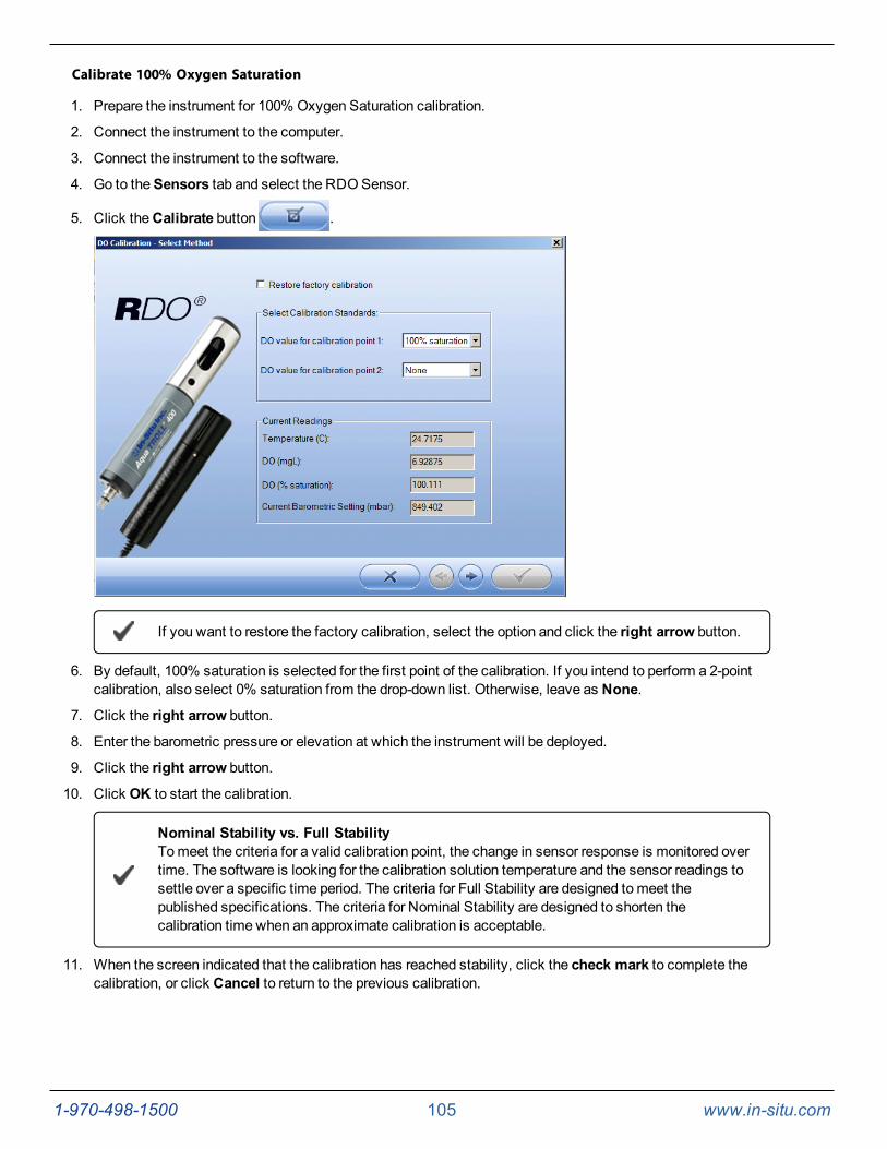
1-970-498-1500 105 www.in-situ.com
Calibrate 100% Oxygen Saturation
1. Prepare the instrument for 100% Oxygen Saturation calibration.
2. Connect the instrument to the computer.
3. Connect the instrument to the software.
4. Go to theSensors tab and select the RDOSensor.
5. Click theCalibrate button .
If you want to restore the factory calibration, select the option and click the right arrow button.
6. By default, 100% saturation is selected for the first point of the calibration. If you intend to perform a 2-pointcalibration, also select 0% saturation from the drop-down list. Otherwise, leave as None.
7. Click the right arrow button.
8. Enter the barometric pressure or elevation at which the instrument will be deployed.
9. Click the right arrow button.
10. Click OK to start the calibration.
Nominal Stability vs. Full StabilityTomeet the criteria for a valid calibration point, the change in sensor response is monitored overtime. The software is looking for the calibration solution temperature and the sensor readings tosettle over a specific time period. The criteria for Full Stability are designed tomeet thepublished specifications. The criteria for Nominal Stability are designed to shorten thecalibration time when an approximate calibration is acceptable.
11. When the screen indicated that the calibration has reached stability, click the check mark to complete thecalibration, or click Cancel to return to the previous calibration.
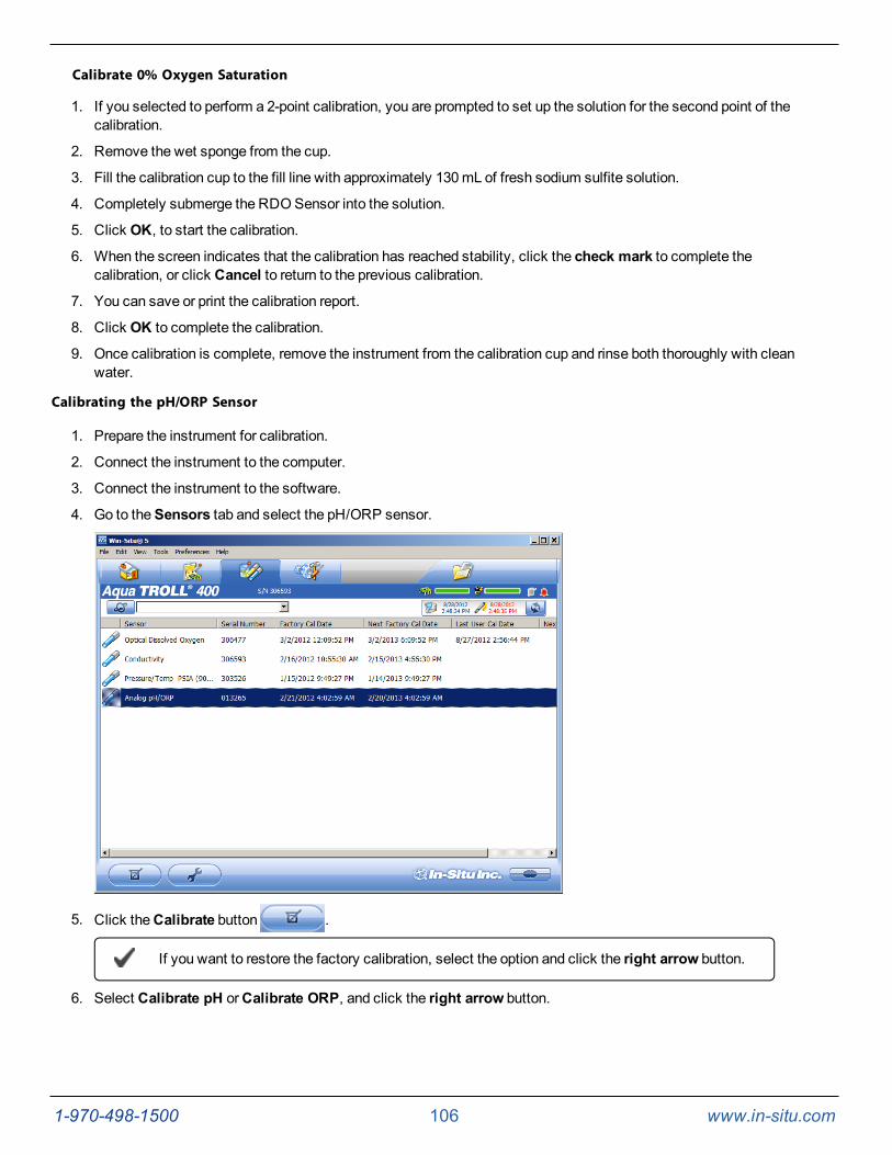
1-970-498-1500 106 www.in-situ.com
Calibrate 0% Oxygen Saturation
1. If you selected to perform a 2-point calibration, you are prompted to set up the solution for the second point of thecalibration.
2. Remove the wet sponge from the cup.
3. Fill the calibration cup to the fill line with approximately 130mL of fresh sodium sulfite solution.
4. Completely submerge the RDOSensor into the solution.
5. Click OK, to start the calibration.
6. When the screen indicates that the calibration has reached stability, click the check mark to complete thecalibration, or click Cancel to return to the previous calibration.
7. You can save or print the calibration report.
8. Click OK to complete the calibration.
9. Once calibration is complete, remove the instrument from the calibration cup and rinse both thoroughly with cleanwater.
Calibrating the pH/ORP Sensor
1. Prepare the instrument for calibration.
2. Connect the instrument to the computer.
3. Connect the instrument to the software.
4. Go to theSensors tab and select the pH/ORP sensor.
5. Click theCalibrate button .
If you want to restore the factory calibration, select the option and click the right arrow button.
6. Select Calibrate pH orCalibrate ORP, and click the right arrow button.
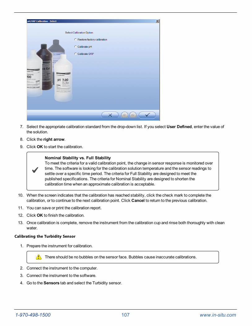
1-970-498-1500 107 www.in-situ.com
7. Select the appropriate calibration standard from the drop-down list. If you select User Defined, enter the value ofthe solution.
8. Click the right arrow.
9. Click OK to start the calibration.
Nominal Stability vs. Full StabilityTomeet the criteria for a valid calibration point, the change in sensor response is monitored overtime. The software is looking for the calibration solution temperature and the sensor readings tosettle over a specific time period. The criteria for Full Stability are designed tomeet thepublished specifications. The criteria for Nominal Stability are designed to shorten thecalibration time when an approximate calibration is acceptable.
10. When the screen indicates that the calibration has reached stability, click the check mark to complete thecalibration, or to continue to the next calibration point. Click Cancel to return to the previous calibration.
11. You can save or print the calibration report.
12. Click OK to finish the calibration.
13. Once calibration is complete, remove the instrument from the calibration cup and rinse both thoroughly with cleanwater.
Calibrating the Turbidity Sensor
1. Prepare the instrument for calibration.
There should be no bubbles on the sensor face. Bubbles cause inaccurate calibrations.
2. Connect the instrument to the computer.
3. Connect the instrument to the software.
4. Go to theSensors tab and select the Turbidity sensor.
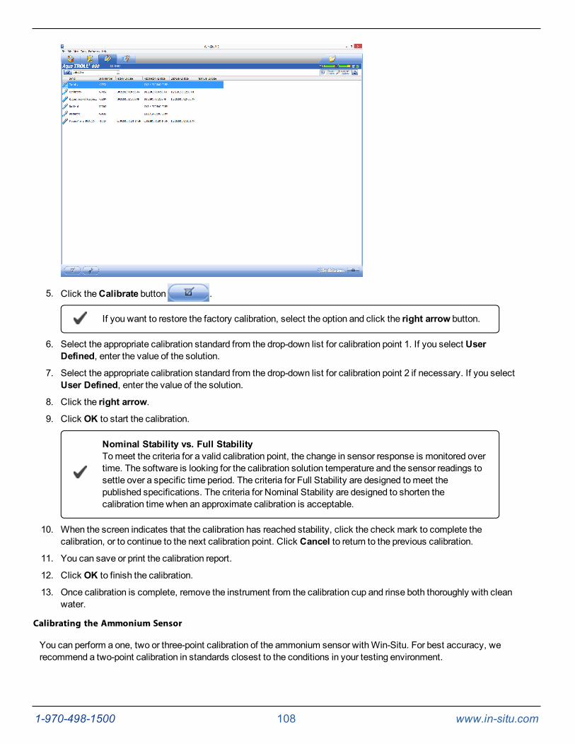
1-970-498-1500 108 www.in-situ.com
5. Click theCalibrate button .
If you want to restore the factory calibration, select the option and click the right arrow button.
6. Select the appropriate calibration standard from the drop-down list for calibration point 1. If you select UserDefined, enter the value of the solution.
7. Select the appropriate calibration standard from the drop-down list for calibration point 2 if necessary. If you selectUser Defined, enter the value of the solution.
8. Click the right arrow.
9. Click OK to start the calibration.
Nominal Stability vs. Full StabilityTomeet the criteria for a valid calibration point, the change in sensor response is monitored overtime. The software is looking for the calibration solution temperature and the sensor readings tosettle over a specific time period. The criteria for Full Stability are designed tomeet thepublished specifications. The criteria for Nominal Stability are designed to shorten thecalibration time when an approximate calibration is acceptable.
10. When the screen indicates that the calibration has reached stability, click the check mark to complete thecalibration, or to continue to the next calibration point. Click Cancel to return to the previous calibration.
11. You can save or print the calibration report.
12. Click OK to finish the calibration.
13. Once calibration is complete, remove the instrument from the calibration cup and rinse both thoroughly with cleanwater.
Calibrating the Ammonium Sensor
You can perform a one, two or three-point calibration of the ammonium sensor withWin-Situ. For best accuracy, werecommend a two-point calibration in standards closest to the conditions in your testing environment.
1-970-498-1500 109 www.in-situ.com
Condition the ammonium sensor for a minimum of two hours prior to calibration bysoaking it in 140 mg/L ammonium as N standard or the highest standard to be usedduring calibration. For the best long term results, soak the sensor overnight.
1. Prepare the instrument for calibration.
There should be no bubbles on the sensor face. Bubbles cause inaccurate calibrations.
2. Connect the instrument to the computer.
3. Connect the instrument to the software.
4. Go to theSensors tab and select the Ammonium sensor.
5. Click theCalibrate button .
If you want to restore the factory calibration, select the option and click the right arrow button.
6. Select the appropriate calibration standard from the drop-down list for calibration point 1. If you select UserDefined, enter the value of the solution.
7. Select the appropriate calibration standard from the drop-down list for calibration point 2. If you select UserDefined, enter the value of the solution.
8. Click the right arrow.
9. Click OK to start the calibration.
Nominal Stability vs. Full StabilityTomeet the criteria for a valid calibration point, the change in sensor response is monitored overtime. The software is looking for the calibration solution temperature and the sensor readings tosettle over a specific time period. The criteria for Full Stability are designed tomeet thepublished specifications. The criteria for Nominal Stability are designed to shorten thecalibration time when an approximate calibration is acceptable.
10. When the screen indicates that the calibration has reached stability, click the check mark to complete thecalibration, or to continue to the next calibration point. Click Cancel to return to the previous calibration.
11. You can save or print the calibration report.
12. Click OK to finish the calibration.
13. Once calibration is complete, remove the instrument from the calibration cup and rinse both thoroughly with cleanwater.
Calibrating the Chloride Sensor
You can perform a one, two or three-point calibration of the chloride sensor withWin-Situ. For best accuracy, we recommenda two-point calibration in standards closest to the conditions in your testing environment.
Condition the chloride sensor for a minimum of two hours prior to calibration by soaking itin 355 mg/L chloride standard or the highest standard to be used during calibration. Forthe best long term results, soak the sensor overnight.
1-970-498-1500 110 www.in-situ.com
1. Prepare the instrument for calibration.
There should be no bubbles on the sensor face. Bubbles cause inaccurate calibrations.
2. Connect the instrument to the computer.
3. Connect the instrument to the software.
4. Go to theSensors tab and select the Chloride sensor.
5. Click theCalibrate button .
If you want to restore the factory calibration, select the option and click the right arrow button.
6. Select the appropriate calibration standard from the drop-down list for calibration point 1. If you select UserDefined, enter the value of the solution.
7. Select the appropriate calibration standard from the drop-down list for calibration point 2. If you select UserDefined, enter the value of the solution.
8. Click the right arrow.
9. Click OK to start the calibration.
Nominal Stability vs. Full StabilityTomeet the criteria for a valid calibration point, the change in sensor response is monitored overtime. The software is looking for the calibration solution temperature and the sensor readings tosettle over a specific time period. The criteria for Full Stability are designed tomeet thepublished specifications. The criteria for Nominal Stability are designed to shorten thecalibration time when an approximate calibration is acceptable.
10. When the screen indicates that the calibration has reached stability, click the check mark to complete thecalibration, or to continue to the next calibration point. Click Cancel to return to the previous calibration.
11. You can save or print the calibration report.
12. Click OK to finish the calibration.
13. Once calibration is complete, remove the instrument from the calibration cup and rinse both thoroughly with cleanwater.
Calibrating the Nitrate Sensor
You can perform a one, two or three-point calibration of the nitrate sensor withWin-Situ. For best accuracy, we recommend atwo-point calibration in standards closest to the conditions in your testing environment.
Condition the nitrate sensor for a minimum of two hours prior to calibration by soaking itin 140 mg/L nitrate as N standard or the highest standard to be used during calibration.For the best long term results, soak the sensor overnight.
1. Prepare the instrument for calibration.
There should be no bubbles on the sensor face. Bubbles cause inaccurate calibrations.
2. Connect the instrument to the computer.
3. Connect the instrument to the software.
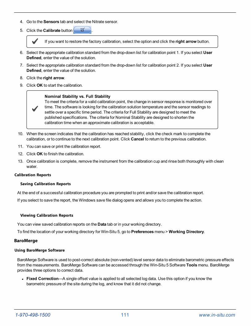
1-970-498-1500 111 www.in-situ.com
4. Go to theSensors tab and select the Nitrate sensor.
5. Click theCalibrate button .
If you want to restore the factory calibration, select the option and click the right arrow button.
6. Select the appropriate calibration standard from the drop-down list for calibration point 1. If you select UserDefined, enter the value of the solution.
7. Select the appropriate calibration standard from the drop-down list for calibration point 2. If you select UserDefined, enter the value of the solution.
8. Click the right arrow.
9. Click OK to start the calibration.
Nominal Stability vs. Full StabilityTomeet the criteria for a valid calibration point, the change in sensor response is monitored overtime. The software is looking for the calibration solution temperature and the sensor readings tosettle over a specific time period. The criteria for Full Stability are designed tomeet thepublished specifications. The criteria for Nominal Stability are designed to shorten thecalibration time when an approximate calibration is acceptable.
10. When the screen indicates that the calibration has reached stability, click the check mark to complete thecalibration, or to continue to the next calibration point. Click Cancel to return to the previous calibration.
11. You can save or print the calibration report.
12. Click OK to finish the calibration.
13. Once calibration is complete, remove the instrument from the calibration cup and rinse both thoroughly with cleanwater.
Calibration Reports
Saving Calibration Reports
At the end of a successful calibration procedure you are prompted to print and/or save the calibration report.
If you select to save the report, theWindows save file dialog opens and allows you to complete the action.
Viewing Calibration Reports
You can view saved calibration reports on theData tab or in your working directory.
To find the location of your working directory forWin-Situ 5, go toPreferencesmenu >Working Directory.
BaroMerge
Using BaroMerge Software
BaroMerge Software is used to post-correct absolute (non-vented) level sensor data to eliminate barometric pressure effectsfrom themeasurements. BaroMerge Software can be accessed through theWin-Situ 5 Software Toolsmenu. BaroMergeprovides three options to correct data.
l Fixed Correction—A single offset value is applied to all selected log data. Use this option if you know thebarometric pressure of the site during the log, and know that it did not change.
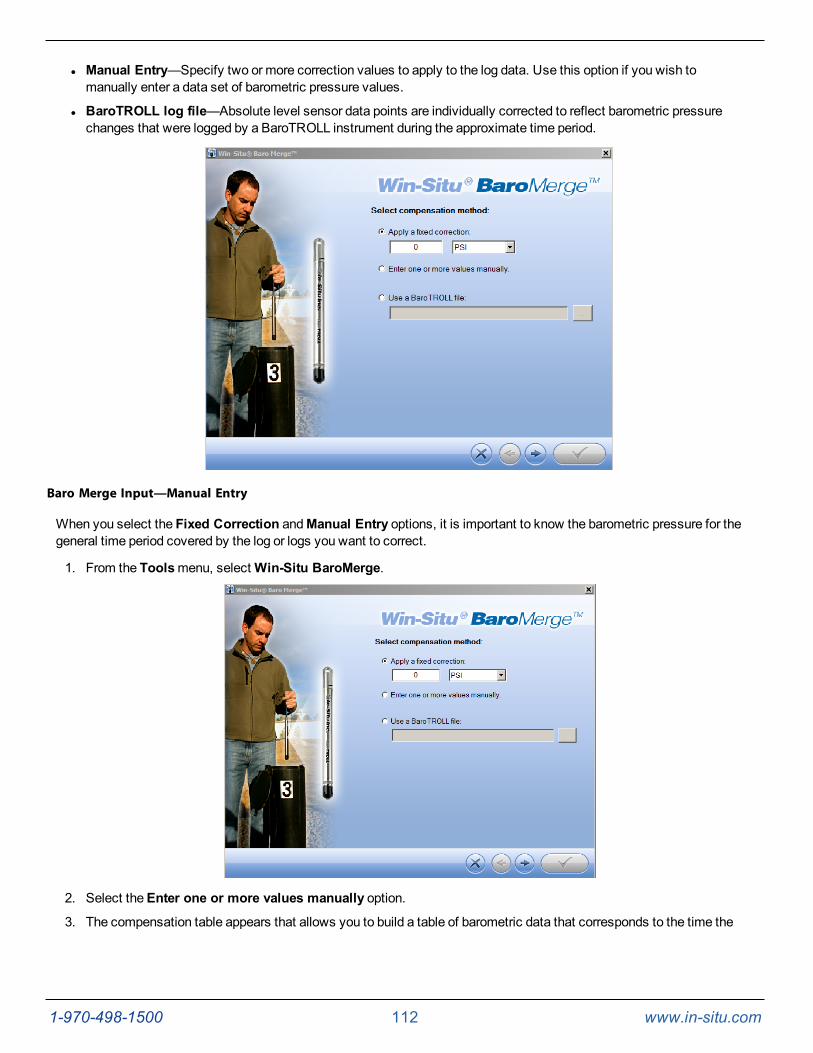
1-970-498-1500 112 www.in-situ.com
l Manual Entry—Specify two or more correction values to apply to the log data. Use this option if you wish tomanually enter a data set of barometric pressure values.
l BaroTROLL log file—Absolute level sensor data points are individually corrected to reflect barometric pressurechanges that were logged by a BaroTROLL instrument during the approximate time period.
Baro Merge Input—Manual Entry
When you select the Fixed Correction andManual Entry options, it is important to know the barometric pressure for thegeneral time period covered by the log or logs you want to correct.
1. From the Toolsmenu, selectWin-Situ BaroMerge.
2. Select theEnter one or more values manually option.
3. The compensation table appears that allows you to build a table of barometric data that corresponds to the time the
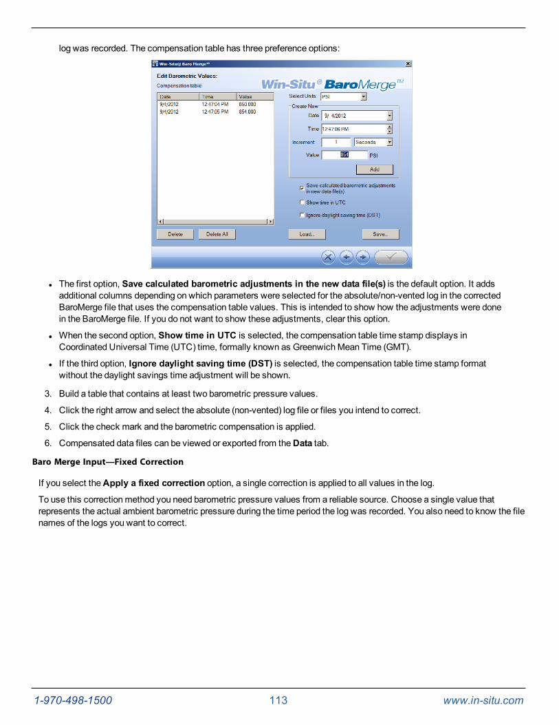
1-970-498-1500 113 www.in-situ.com
log was recorded. The compensation table has three preference options:
l The first option, Save calculated barometric adjustments in the new data file(s) is the default option. It addsadditional columns depending on which parameters were selected for the absolute/non-vented log in the correctedBaroMerge file that uses the compensation table values. This is intended to show how the adjustments were donein the BaroMerge file. If you do not want to show these adjustments, clear this option.
l When the second option, Show time in UTC is selected, the compensation table time stamp displays inCoordinated Universal Time (UTC) time, formally known as GreenwichMean Time (GMT).
l If the third option, Ignore daylight saving time (DST) is selected, the compensation table time stamp formatwithout the daylight savings time adjustment will be shown.
3. Build a table that contains at least two barometric pressure values.
4. Click the right arrow and select the absolute (non-vented) log file or files you intend to correct.
5. Click the check mark and the barometric compensation is applied.
6. Compensated data files can be viewed or exported from theData tab.
Baro Merge Input—Fixed Correction
If you select theApply a fixed correction option, a single correction is applied to all values in the log.
To use this correctionmethod you need barometric pressure values from a reliable source. Choose a single value thatrepresents the actual ambient barometric pressure during the time period the log was recorded. You also need to know the filenames of the logs you want to correct.

1-970-498-1500 114 www.in-situ.com
1. From the Toolsmenu, selectWin-Situ Baro Merge.
2. Select theApply a fixed correction option.
3. Enter the barometric correction value and select units from the drop-downmenu.
4. Click the right arrow button.
5. Select the log files to which the correction will be applied and click the check mark button.
6. Compensated data files can be viewed or exported from theData tab.
BaroMerge Input—BaroTROLL File
Log files that contain absolute data can be barometrically compensated using values logged by the In-Situ Inc. BaroTROLLInstrument. Select this method when you have access to a BaroTROLL log file covering approximately the same time periodas the data file you intend to correct.
To use this correctionmethod, you need the name of the BaroTROLL log file and the name(s) of the absolute log file(s) youwant to correct.
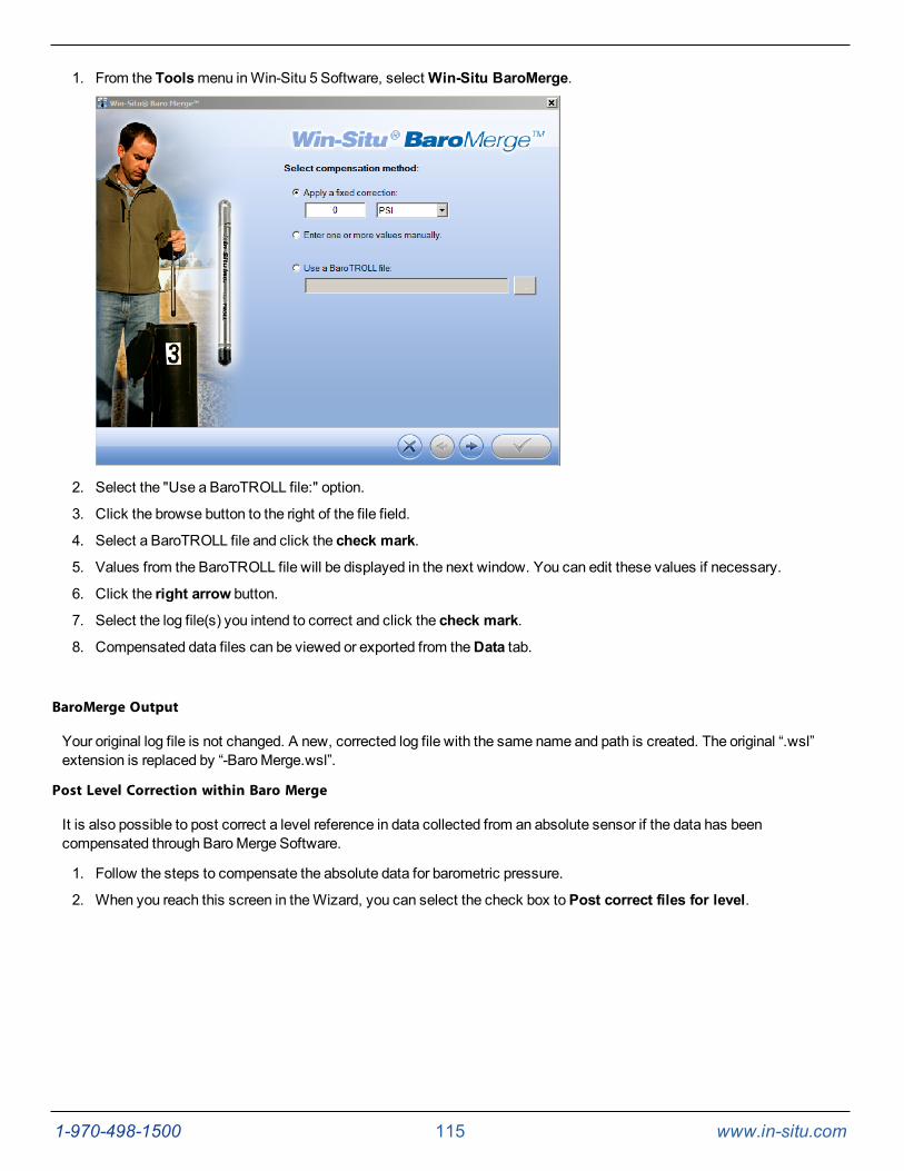
1-970-498-1500 115 www.in-situ.com
1. From the Toolsmenu inWin-Situ 5 Software, selectWin-Situ BaroMerge.
2. Select the "Use a BaroTROLL file:" option.
3. Click the browse button to the right of the file field.
4. Select a BaroTROLL file and click the check mark.
5. Values from the BaroTROLL file will be displayed in the next window. You can edit these values if necessary.
6. Click the right arrow button.
7. Select the log file(s) you intend to correct and click the check mark.
8. Compensated data files can be viewed or exported from theData tab.
BaroMerge Output
Your original log file is not changed. A new, corrected log file with the same name and path is created. The original “.wsl”extension is replaced by “-BaroMerge.wsl”.
Post Level Correction within Baro Merge
It is also possible to post correct a level reference in data collected from an absolute sensor if the data has beencompensated through BaroMerge Software.
1. Follow the steps to compensate the absolute data for barometric pressure.
2. When you reach this screen in theWizard, you can select the check box toPost correct files for level.
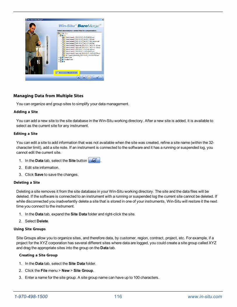
1-970-498-1500 116 www.in-situ.com
Managing Data from Multiple Sites
You can organize and group sites to simplify your datamanagement.
Adding a Site
You can add a new site to the site database in theWin-Situ working directory. After a new site is added, it is available toselect as the current site for any instrument.
Editing a Site
You can edit a site to add information that was not available when the site was created, refine a site name (within the 32-character limit), add a site note. If an instrument is connected to the software and it has a running or suspended log, youcannot edit the current site.
1. In theData tab, select theSite button .
2. Edit site information.
3. Click Save to save the changes.
Deleting a Site
Deleting a site removes it from the site database in yourWin-Situ working directory. The site and the data files will bedeleted. If the software is connected to an instrument with a running or suspended log the current site cannot be deleted. Ifwhile disconnected you inadvertently delete a site that is stored in one of your instruments, Win-Situ will restore it the nexttime you connect to the instrument.
1. In theData tab, expand theSite Data folder and right-click the site.
2. Select Delete.
Using Site Groups
Site Groups allow you to organize sites, and therefore data, by customer, region, contract, project, etc. For example, if aproject for the XYZ corporation has several different sites where data are logged, you could create a site group called XYZand drag the appropriate sites into the group on theData tab.
Creating a Site Group
1. In theData tab, select theSite Data folder.
2. Click the Filemenu > New > Site Group.
3. Enter a name for the site group. A site group name can have up to 100 characters.
1-970-498-1500 117 www.in-situ.com
4. Click Save.
5. The new site group appears in the folder tree with the symbol . The site group does not yet have sites associatedwith it.
6. To place existing sites into your new site group, select one or more sites in the folder tree, drag and drop themunder the new group.
Site-Based Connections
Win-Situ allows you to create connection configurations for individual sites. In this way you can easily maintain differentcommunication setups for different sites. The site connection configuration dialog lets you configure and name a connectionfor the site. When first created, the site connection settings are initialized from the default communication settings(Preferencesmenu > Comm Settings).
Creating a Custom Connection
1. In theData tab, select theConnections folder.
2. Select File > New > Connection.
3. Enter a name for the new connection.
4. Select the options you want for the new connection.
5. Click Save.
Using a Custom Connection
1. OpenWin-Situ but do not connect to the instrument.
2. Select the custom connection in the folder tree on theData tab.
3. Click theConnect button to connect to the instrument using the custom configuration.
Storing Custom Connection for a Site
Once a custom connection has been created, it will appear in theConnections area of theSite Information screen and canbe selected for use with any site.
Correcting a Level Reference in Data Files
About Post Correcting Level Data
In specific cases, it is possible to correct a level reference in a data file after you have stopped the log and downloaded thedata. The following criteria must bemet in order for a level reference to be post corrected in a data file.
l Datamust be compensated for barometric pressure before the level reference can be corrected. Therefore, datamust come from a vented instrument, or if it is from an absolute instrument, it must be compensated through BaroMerge Software before the level reference can be corrected.
l The data file must already contain a level mode.
l The data file must have been created withWin-Situ version 5.6.0.0 or higher in order to post correct for the Depthreference type.
l The datamust have been downloaded withWin-Situ version 5.6.24.4 or higher.
l If the log was originally set to "Zero at start of test" and the user has made changes to the level reference duringlogging, it is not possible to correct the data withWin-Situ.
Files that have been corrected are stored in a subdirectory named "Post Corrected Files" and "PostLevelCorrection" is addedto the file name. The original data file is not altered.
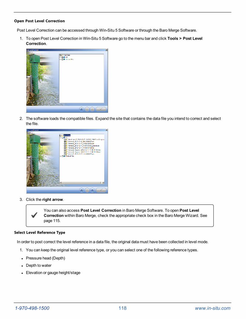
1-970-498-1500 118 www.in-situ.com
Open Post Level Correction
Post Level Correction can be accessed throughWin-Situ 5 Software or through the BaroMerge Software.
1. To open Post Level Correction inWin-Situ 5 Software go to themenu bar and click Tools > Post LevelCorrection.
2. The software loads the compatible files. Expand the site that contains the data file you intend to correct and selectthe file.
3. Click the right arrow.
You can also access Post Level Correction in BaroMerge Software. To openPost LevelCorrectionwithin BaroMerge, check the appropriate check box in the BaroMergeWizard. Seepage 115.
Select Level Reference Type
In order to post correct the level reference in a data file, the original datamust have been collected in level mode.
1. You can keep the original level reference type, or you can select one of the following reference types.
l Pressure head (Depth)
l Depth to water
l Elevation or gauge height/stage
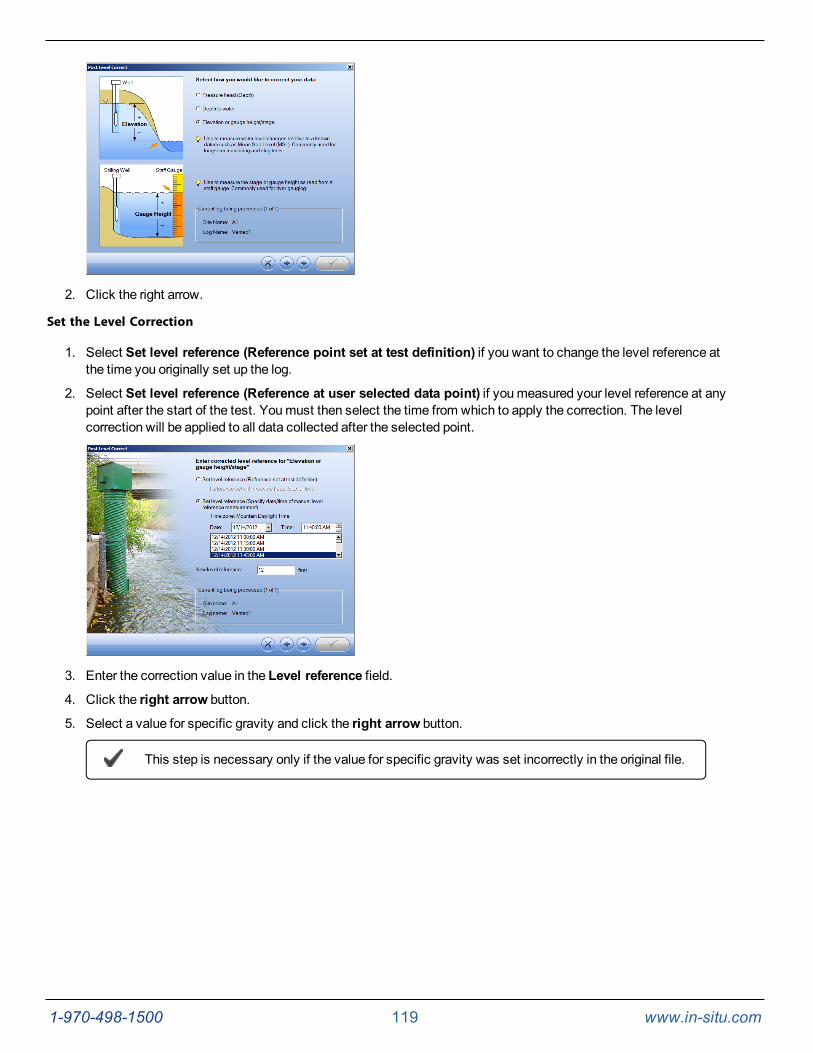
1-970-498-1500 119 www.in-situ.com
2. Click the right arrow.
Set the Level Correction
1. Select Set level reference (Reference point set at test definition) if you want to change the level reference atthe time you originally set up the log.
2. Select Set level reference (Reference at user selected data point) if youmeasured your level reference at anypoint after the start of the test. Youmust then select the time from which to apply the correction. The levelcorrection will be applied to all data collected after the selected point.
3. Enter the correction value in the Level reference field.
4. Click the right arrow button.
5. Select a value for specific gravity and click the right arrow button.
This step is necessary only if the value for specific gravity was set incorrectly in the original file.
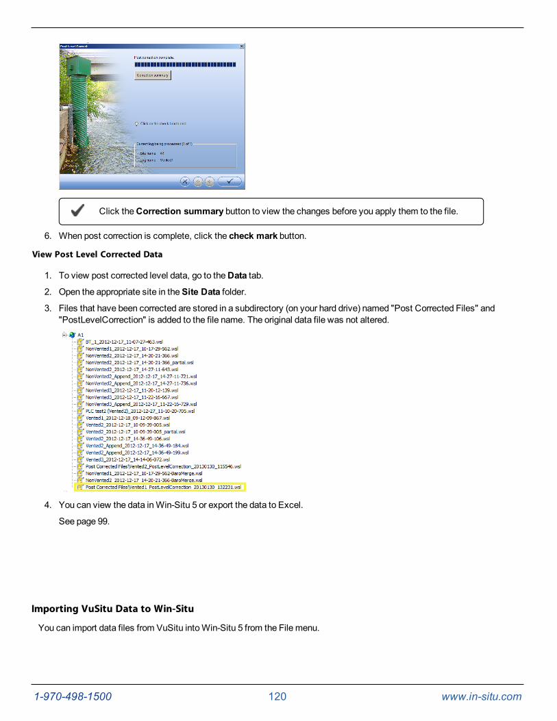
1-970-498-1500 120 www.in-situ.com
Click theCorrection summary button to view the changes before you apply them to the file.
6. When post correction is complete, click the check mark button.
View Post Level Corrected Data
1. To view post corrected level data, go to theData tab.
2. Open the appropriate site in theSite Data folder.
3. Files that have been corrected are stored in a subdirectory (on your hard drive) named "Post Corrected Files" and"PostLevelCorrection" is added to the file name. The original data file was not altered.
4. You can view the data inWin-Situ 5 or export the data to Excel.
See page 99.
Importing VuSitu Data to Win-Situ
You can import data files from VuSitu intoWin-Situ 5 from the File menu.
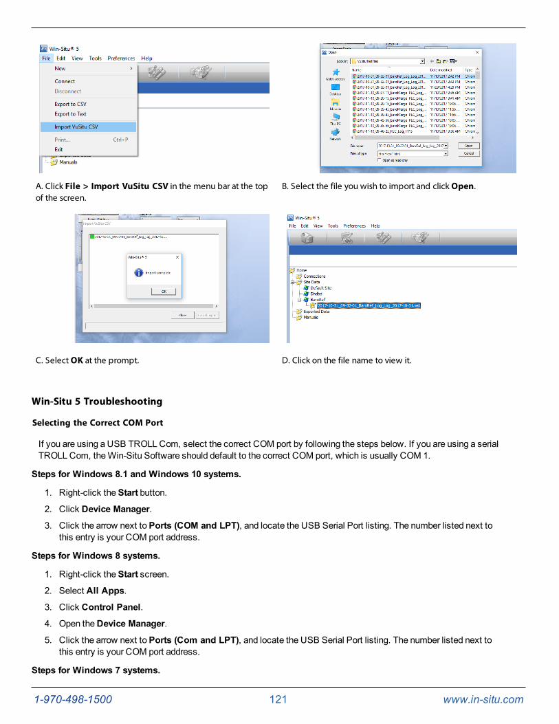
1-970-498-1500 121 www.in-situ.com
A. Click File > Import VuSitu CSV in the menu bar at the topof the screen.
B. Select the file you wish to import and click Open.
C. Select OK at the prompt. D. Click on the file name to view it.
Win-Situ 5 Troubleshooting
Selecting the Correct COM Port
If you are using a USB TROLLCom, select the correct COM port by following the steps below. If you are using a serialTROLLCom, theWin-Situ Software should default to the correct COM port, which is usually COM 1.
Steps for Windows 8.1 and Windows 10 systems.
1. Right-click theStart button.
2. Click Device Manager.
3. Click the arrow next toPorts (COM and LPT), and locate the USB Serial Port listing. The number listed next tothis entry is your COM port address.
Steps for Windows 8 systems.
1. Right-click theStart screen.
2. Select All Apps.
3. Click Control Panel.
4. Open theDevice Manager.
5. Click the arrow next toPorts (Com and LPT), and locate the USB Serial Port listing. The number listed next tothis entry is your COM port address.
Steps for Windows 7 systems.
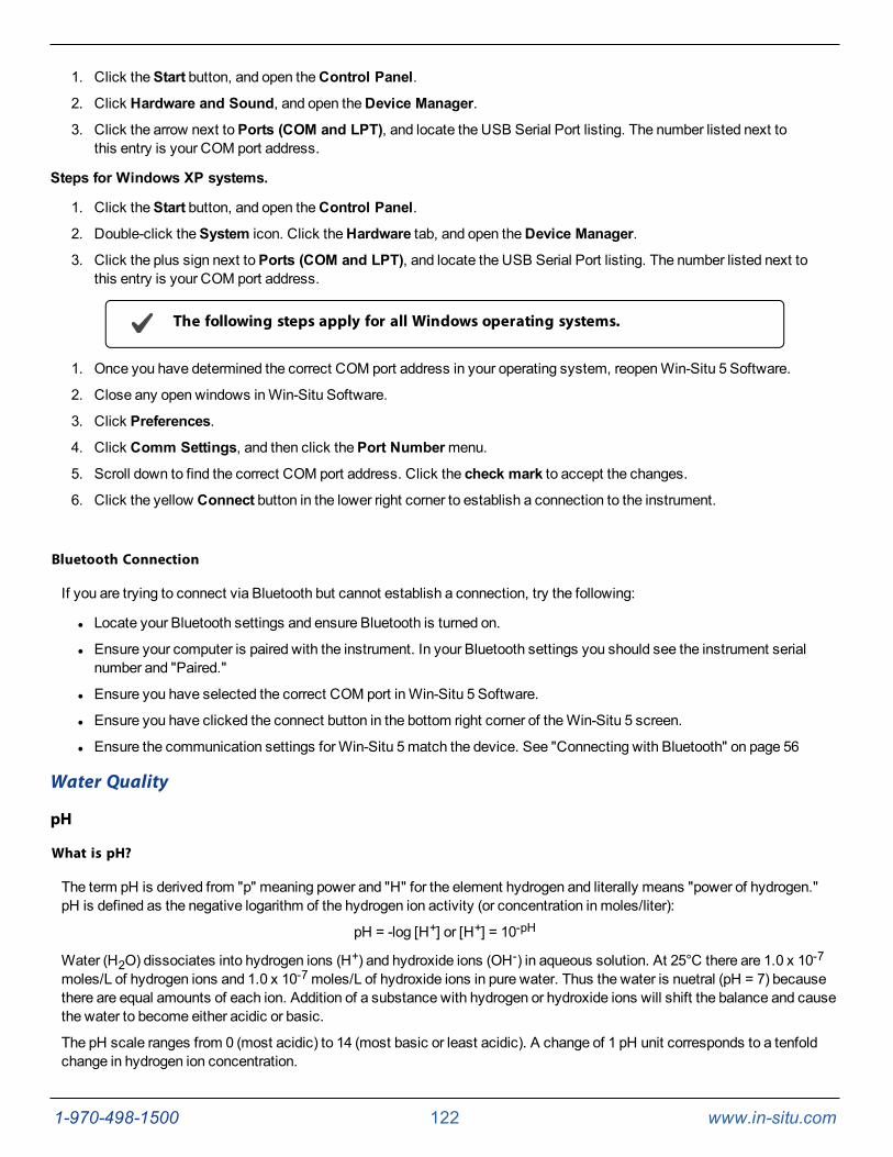
1-970-498-1500 122 www.in-situ.com
1. Click theStart button, and open theControl Panel.
2. Click Hardware and Sound, and open theDevice Manager.
3. Click the arrow next toPorts (COM and LPT), and locate the USB Serial Port listing. The number listed next tothis entry is your COM port address.
Steps for Windows XP systems.
1. Click theStart button, and open theControl Panel.
2. Double-click theSystem icon. Click theHardware tab, and open theDevice Manager.
3. Click the plus sign next toPorts (COM and LPT), and locate the USB Serial Port listing. The number listed next tothis entry is your COM port address.
The following steps apply for all Windows operating systems.
1. Once you have determined the correct COM port address in your operating system, reopenWin-Situ 5 Software.
2. Close any open windows inWin-Situ Software.
3. Click Preferences.
4. Click Comm Settings, and then click thePort Numbermenu.
5. Scroll down to find the correct COM port address. Click the check mark to accept the changes.
6. Click the yellow Connect button in the lower right corner to establish a connection to the instrument.
Bluetooth Connection
If you are trying to connect via Bluetooth but cannot establish a connection, try the following:
l Locate your Bluetooth settings and ensure Bluetooth is turned on.
l Ensure your computer is paired with the instrument. In your Bluetooth settings you should see the instrument serialnumber and "Paired."
l Ensure you have selected the correct COM port inWin-Situ 5 Software.
l Ensure you have clicked the connect button in the bottom right corner of theWin-Situ 5 screen.
l Ensure the communication settings forWin-Situ 5match the device. See "Connecting with Bluetooth" on page 56
Water Quality
pH
What is pH?
The term pH is derived from "p" meaning power and "H" for the element hydrogen and literally means "power of hydrogen."pH is defined as the negative logarithm of the hydrogen ion activity (or concentration in moles/liter):
pH = -log [H+] or [H+] = 10-pH
Water (H2O) dissociates into hydrogen ions (H+) and hydroxide ions (OH-) in aqueous solution. At 25°C there are 1.0 x 10⁻⁷moles/L of hydrogen ions and 1.0 x 10⁻⁷moles/L of hydroxide ions in pure water. Thus the water is nuetral (pH = 7) becausethere are equal amounts of each ion. Addition of a substance with hydrogen or hydroxide ions will shift the balance and causethe water to become either acidic or basic.
The pH scale ranges from 0 (most acidic) to 14 (most basic or least acidic). A change of 1 pH unit corresponds to a tenfoldchange in hydrogen ion concentration.
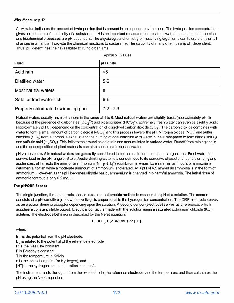
1-970-498-1500 123 www.in-situ.com
Why Measure pH?
A pH value indicates the amount of hydrogen ion that is present in an aqueous environment. The hydrogen ion concentrationgives an indication of the acidity of a substance. pH is an important measurement in natural waters becausemost chemicaland biochemical processes are pH dependent. The physiological chemistry of most living organisms can tolerate only smallchanges in pH and still provide the chemical reactions to sustain life. The solubility of many chemicals is pH dependent.Thus, pH determines their availability to living organisms.
Typical pH values
Fluid pH units
Acid rain <5
Distilled water 5.6
Most nautral waters 8
Safe for freshwater fish 6-9
Properly chlorinated swimming pool 7.2 - 7.6
Natural waters usually have pH values in the range of 4 to 9. Most natural waters are slightly basic (approximately pH 8)because of the presence of carbonates (CO32-) and bicarbonates (HCO3-). Extremely fresh water can even be slightly acidic(approximately pH 6), depending on the concentration of dissolved carbon dioxide (CO2). The carbon dioxide combines withwater to form a small amount of carbonic acid (H2CO3) and this process lowers the pH. Nitrogen oxides (NOx) and sulfurdioxides (SO2) from automobile exhaust and the burning of coal combine with water in the atmosphere to form nitric (HNO3)and sulfuric acid (H2SO4). This falls to the ground as acid rain and accumulates in surface water. Runoff frommining spoilsand the decomposition of plant materials can also cause acidic surface water.
pH values below 5 in natural waters are generally considered to be too acidic for most aquatic organisms. Freshwater fishsurvive best in the pH range of 6 to 9. Acidic drinking water is a concern due to its corrosive characteristics to plumbing andappliances. pH affects the ammonia/ammonium (NH3/NH4+) equilibrium in water. Even a small ammount of ammonia isdetrimental to fish while amoderate ammount of ammonium is tolerated. At a pH of 6.5 almost all ammonia is in the form ofammonium. However, as the pH becomes slightly basic, ammonium is changed into harmful ammonia. The lethal dose ofammonia for trout is only 0.2mg/L.
The pH/ORP Sensor
The single-junction, three-electrode sensor uses a potentiometric method tomeasure the pH of a solution. The sensorconsists of a pH-sensitive glass whose voltage is proportional to the hydrogen ion concentration. TheORP electrode servesas an electron donor or acceptor depending upon the solution. A second sensor (electrode) serves as a reference, whichsupplies a constant stable output. Electrical contact is made with the solution using a saturated potassium chloride (KCl)solution. The electrode behavior is described by the Nerst equation:
Em = Eo + (2.3RT/nF) log [H+]
where
Em is the potential from the pH electrode,Eo is related to the potential of the reference electrode,R is the Gas Law constant,F is Faraday's constant,T is the temperature in Kelvin,n is the ionic charge (+1 for Hydrogen), and[H+] is the hydrogen ion concentration in moles/L.
The instrument reads the signal from the pH electrode, the reference electrode, and the temperature and then calculates thepH using the Nerst equation.
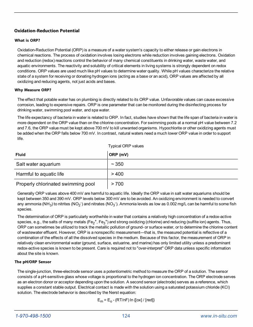
1-970-498-1500 124 www.in-situ.com
Oxidation-Reduction Potential
What is ORP?
Oxidation-Reduction Potential (ORP) is ameasure of a water system's capacity to either release or gain electrons inchemical reactions. The process of oxidation involves losing electrons while reduction involves gaining electrons. Oxidationand reduction (redox) reactions control the behavior of many chemical constituents in drinking water, waste water, andaquatic environments. The reactivity and solubility of critical elements in living systems is strongly dependent on redoxconditions. ORP values are usedmuch like pH values to determine water quality. While pH values characterize the relativestate of a system for receiving or donating hydrogen ions (acting as a base or an acid), ORP values are affected by alloxidizing and reducing agents, not just acids and bases.
Why Measure ORP?
The effect that potable water has on plumbing is directly related to its ORP value. Unfavorable values can cause excessivecorrosion, leading to expensive repairs. ORP is one parameter that can bemonitored during the disinfecting process fordrinking water, swimming pool water, and spa water.
The life expectancy of bacteria in water is related to ORP. In fact, studies have shown that the life span of bacteria in water ismore dependent on the ORP value than on the chlorine concentration. For swimming pools at a normal pH value between 7.2and 7.6, the ORP valuemust be kept above 700mV to kill unwanted organisms. Hypochlorite or other oxidizing agents mustbe added when theORP falls below 700mV. In contrast, natural waters need amuch lower ORP value in order to supportlife.
Typical ORP values
Fluid ORP (mV)
Salt water aquarium ~ 350
Harmful to aquatic life > 400
Properly chlorinated swimming pool > 700
Generally ORP values above 400mV are harmful to aquatic life. Ideally the ORP value in salt water aquariums should bekept between 350 and 390mV. ORP levels below 300mV are to be avoided. An oxidizing environment is needed to convertany ammonia (NH3) to nitrites (NO2-) and nitrates (NO3-). Ammonia levels as low as 0.002mg/L can be harmful to some fishspecies.
The determination of ORP is particularly worthwhile in water that contains a relatively high concentration of a redox-activespecies, e.g., the salts of many metals (Fe2+, Fe3+) and strong oxidizing (chlorine) and reducing (sulfite ion) agents. Thus,ORP can sometimes be utilized to track themetallic pollution of ground- or surface water, or to determine the chlorine contentof wastewater effluent. However, ORP is a nonspecific measurement—that is, themeasured potential is reflective of acombination of the effects of all the dissolved species in themedium. Because of this factor, themeasurement of ORP inrelatively clean environmental water (ground, surface, estuarine, andmarine) has only limited utility unless a predominantredox-active species is known to be present. Care is required not to "over-interpret" ORP data unless specific informationabout the site is known.
The pH/ORP Sensor
The single-junction, three-electrode sensor uses a potentiometric method tomeasure the ORP of a solution. The sensorconsists of a pH-sensitive glass whose voltage is proportional to the hydrogen ion concentration. TheORP electrode servesas an electron donor or acceptor depending upon the solution. A second sensor (electrode) serves as a reference, whichsupplies a constant stable output. Electrical contact is made with the solution using a saturated potassium chloride (KCl)solution. The electrode behavior is described by the Nerst equation:
Em = Eo - (RT/nF) ln {[ox] / [red]}
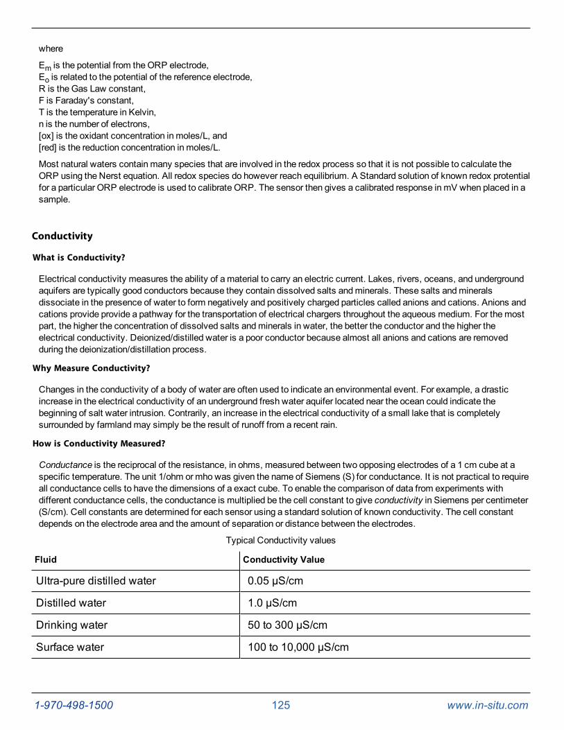
1-970-498-1500 125 www.in-situ.com
where
Em is the potential from theORP electrode,Eo is related to the potential of the reference electrode,R is the Gas Law constant,F is Faraday's constant,T is the temperature in Kelvin,n is the number of electrons,[ox] is the oxidant concentration in moles/L, and[red] is the reduction concentration in moles/L.
Most natural waters contain many species that are involved in the redox process so that it is not possible to calculate theORP using the Nerst equation. All redox species do however reach equilibrium. A Standard solution of known redox protentialfor a particular ORP electrode is used to calibrate ORP. The sensor then gives a calibrated response inmV when placed in asample.
Conductivity
What is Conductivity?
Electrical conductivity measures the ability of amaterial to carry an electric current. Lakes, rivers, oceans, and undergroundaquifers are typically good conductors because they contain dissolved salts andminerals. These salts andmineralsdissociate in the presence of water to form negatively and positively charged particles called anions and cations. Anions andcations provide provide a pathway for the transportation of electrical chargers throughout the aqueous medium. For themostpart, the higher the concentration of dissolved salts andminerals in water, the better the conductor and the higher theelectrical conductivity. Deionized/distilled water is a poor conductor because almost all anions and cations are removedduring the deionization/distillation process.
Why Measure Conductivity?
Changes in the conductivity of a body of water are often used to indicate an environmental event. For example, a drasticincrease in the electrical conductivity of an underground fresh water aquifer located near the ocean could indicate thebeginning of salt water intrusion. Contrarily, an increase in the electrical conductivity of a small lake that is completelysurrounded by farmlandmay simply be the result of runoff from a recent rain.
How is Conductivity Measured?
Conductance is the reciprocal of the resistance, in ohms, measured between two opposing electrodes of a 1 cm cube at aspecific temperature. The unit 1/ohm ormhowas given the name of Siemens (S) for conductance. It is not practical to requireall conductance cells to have the dimensions of a exact cube. To enable the comparison of data from experiments withdifferent conductance cells, the conductance is multiplied be the cell constant to give conductivity in Siemens per centimeter(S/cm). Cell constants are determined for each sensor using a standard solution of known conductivity. The cell constantdepends on the electrode area and the amount of separation or distance between the electrodes.
Typical Conductivity values
Fluid Conductivity Value
Ultra-pure distilled water 0.05 µS/cm
Distilled water 1.0 µS/cm
Drinking water 50 to 300 µS/cm
Surface water 100 to 10,000 µS/cm

1-970-498-1500 126 www.in-situ.com
Fluid Conductivity Value
Sea water 40,000 to 55,000 µS/cm
Great Salt Lake 158,000 µS/cm
Early conductivity measurements were performed using cells with two electrodes. This method required using threeconductivity cells with different cell constraints in order to span the range of 1 to 100,000microSiemens per centimeter(µS/cm). Another inconvenience occured when deposits formed on electrodes, thus reducing themeasured conductivity ofthe sample.
Themodern four-electrode conductivity cell offers many advantages over the two-electrodemethod. It contains two driveelectrodes and two sensing electrodes. The sensing electrodes are positioned in a low current area so that electrode foulingis minimized. An alternating current is used to drive the cell. This reduces errors caused by polarization resulting from theapplication of direct current.
Dissolved Oxygen
What is Dissolved Oxygen?
The amount of dissolved oxygen (DO) in both natural water and wastewater is a function of several parameters. DO is highlydependent on temperature and atmospheric pressure. An increase in temperature causes a decrease in the amount of oxygenthat can dissolve in water. Conversely, higher atmospheric pressures result in higher DO values. Salinity is also a factor.Oxygen solubility is greater in freshwater than in salt water. There are also chemical and biochemical processes that affectDO.
Most of the dissolved oxygen in water comes from the atmosphere, but oxygen from the photosynthesis of aquatic plants isalso a key source. DO levels in lakes and other surface water will actually follow a cyclic or diurnal pattern over the course ofa day, rising and falling as light intensity changes from dawn to dusk.
Why Measure DO?
Most aquatic life requires an average DO value greater than 5.0milligrams dissolved oxygen per liter of water (mg/L) in orderto survive. Although the amount of dissolved oxygen in a body of water fluctuates due to natural processes, large deviationsfrom normal levels are usually a result of human activity. Changes in DO levels are usually the result of a buildup in organicwaste. Organic waste can enter surface water from treatment facilities, runoff from agricultural feed lots or domestic areas,and from industrial discharge. Organic wastes often contain nitrates and phosphates. Nitrates and phosphates are nutrientsfor aquatic plants and algae, stimulating overproduction when present in excessive levels. Accelerated growth of bloomsincrease the number of photosynthesizing plants, which temporarily increases the amount of dissolved oxygen. Howeversubmerged aquatic vegetation eventually experience a reduction in sunlight die to increased coverage on the surface. Thisdecrease in sunlight leads to a reduction in photosynthesis and eventual death. Bacterial processes take over and consumeevenmore dissolved oxygen. Fish and other aquatic species die due to lack of dissolved oxygen. This tragic process is knowas eutrophication.
Typical DO values
Conditions DO Value
100% DO, 0°C, 1 atm, 0 ppm Chlorine* 14.6 mg/L
100% DO, 20°C, 1 atm, 0 ppm Chlorine 9.09 mg/L
100% DO, 0°C, 0.75 atm, 0 ppm Chlorine 6.77 mg/L
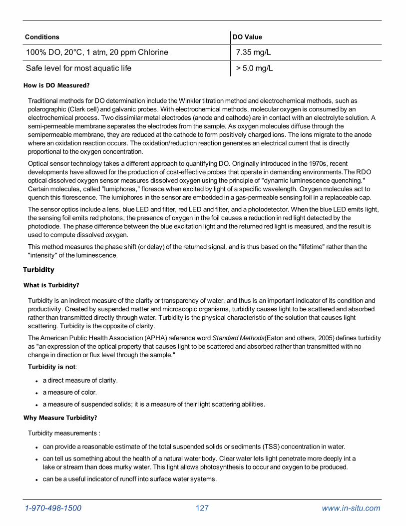
1-970-498-1500 127 www.in-situ.com
Conditions DO Value
100% DO, 20°C, 1 atm, 20 ppm Chlorine 7.35 mg/L
Safe level for most aquatic life > 5.0 mg/L
How is DO Measured?
Traditional methods for DO determination include theWinkler titrationmethod and electrochemical methods, such aspolarographic (Clark cell) and galvanic probes. With electrochemical methods, molecular oxygen is consumed by anelectrochemical process. Two dissimilar metal electrodes (anode and cathode) are in contact with an electrolyte solution. Asemi-permeablemembrane separates the electrodes from the sample. As oxygenmolecules diffuse through thesemipermeablemembrane, they are reduced at the cathode to form positively charged ions. The ions migrate to the anodewhere an oxidation reaction occurs. The oxidation/reduction reaction generates an electrical current that is directlyproportional to the oxygen concentration.
Optical sensor technology takes a different approach to quantifying DO. Originally introduced in the 1970s, recentdevelopments have allowed for the production of cost-effective probes that operate in demanding environments.The RDOoptical dissolved oxygen sensor measures dissolved oxygen using the principle of "dynamic luminescence quenching."Certain molecules, called "lumiphores," floresce when excited by light of a specific wavelength. Oxygenmolecules act toquench this florescence. The lumiphores in the sensor are embedded in a gas-permeable sensing foil in a replaceable cap.
The sensor optics include a lens, blue LED and filter, red LED and filter, and a photodetector. When the blue LED emits light,the sensing foil emits red photons; the presence of oxygen in the foil causes a reduction in red light detected by thephotodiode. The phase difference between the blue excitation light and the returned red light is measured, and the result isused to compute dissolved oxygen.
This methodmeasures the phase shift (or delay) of the returned signal, and is thus based on the "lifetime" rather than the"intensity" of the luminescence.
Turbidity
What is Turbidity?
Turbidity is an indirect measure of the clarity or transparency of water, and thus is an important indicator of its condition andproductivity. Created by suspendedmatter andmicroscopic organisms, turbidity causes light to be scattered and absorbedrather than transmitted directly through water. Turbidity is the physical characteristic of the solution that causes lightscattering. Turbidity is the opposite of clarity.
The American Public Health Association (APHA) reference wordStandardMethods(Eaton and others, 2005) defines turbidityas "an expression of the optical property that causes light to be scattered and absorbed rather than transmitted with nochange in direction or flux level through the sample."
Turbidity is not:
l a direct measure of clarity.
l ameasure of color.
l ameasure of suspended solids; it is ameasure of their light scattering abilities.
Why Measure Turbidity?
Turbidity measurements :
l can provide a reasonable estimate of the total suspended solids or sediments (TSS) concentration in water.
l can tell us something about the health of a natural water body. Clear water lets light penetrate more deeply int alake or stream than does murky water. This light allows photosynthesis to occur and oxygen to be produced.
l can be a useful indicator of runoff into surface water systems.
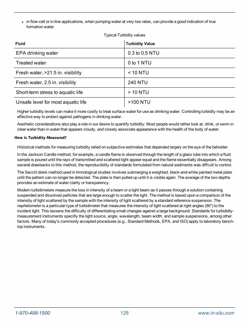
1-970-498-1500 128 www.in-situ.com
l in flow-cell or in-line applications, when pumping water at very low rates, can provide a good indication of trueformation water.
Typical Turbidity values
Fluid Turbidity Value
EPA drinking water 0.3 to 0.5 NTU
Treated water 0 to 1 NTU
Fresh water, >21.5 in. visibility < 10 NTU
Fresh water, 2.5 in. visibility 240 NTU
Short-term stress to aquatic life > 10 NTU
Unsafe level for most aquatic life >100 NTU
Higher turbidity levels canmake it more costly to treat surface water for use as drinking water. Controlling turbidity may be aneffective way to protect against pathogens in drinking water.
Aesthetic considerations also play a role in our desire to quantify turbidity: Most people would rather look at, drink, or swim inclear water than in water that appears cloudy, and closely associate appearance with the health of the body of water.
How is Turbidity Measured?
Historical methods for measuring turbidity relied on subjective estimates that depended largely on the eye of the beholder.
In the Jackson Candlemethod, for example, a candle flame is observed through the length of a glass tube into which a fluidsample is poured until the rays of transmitted and scattered light appear equal and the flame essentially disappears. Amongseveral drawbacks to this method, the reproducibility of standards formulated from natural sediments was diffcult to control.
The Secchi diskk method used in limnological studies involves submerging a weighted, black-and-white paintedmetal plateuntil the pattern can no longer be detected. The plate is then pulled up until it is visible again. The average of the two depthsprovides an estimate of water clarity or transparency.
Modern turbidimeters measure the loss in intensity of a beam or a light beam as it passes through a solution containingsuspended and dissolved particles that are large enough to scatter the light. Themethod is based upon a comparison of theintensity of light scattered by the sample with the intensity of light scattered by a standard reference suspension. Thenephelometer is a particular type of turbidimeter that measures the intensity of light scattered at right angles (90°) to theincident light. This lessens the difficulty of differentiating small changes against a large background. Standards for turbididty-measurement instruments specifiy the light source, angle, wavelength, beam width, and sample suspensions, among otherfactors. Many of today's commonly accepted procedures (e.g., StandardMethods, EPA, and ISO) apply to laboratory bench-top instruments.
1-970-498-1500 129 www.in-situ.com
Care and Maintenance
Maintenance Schedule
For best results, send the instrument to themanufacturer for factory calibration every 12 to 18months.
User-Serviceable Parts
The user-serviceable parts on the instrument include the O-rings, the RDO, pH/ORP, conductivity, temperature, and turbiditysensors, and the RDOSensor Cap.
O-rings
The instrument has several O-rings that can bemaintained by the user in order to keepmoisture from entering the instrumentand damaging the electronics. Apply a very thin layer of vacuum grease to new O-rings upon installation. Check O-rings forcracks, chips, or discoloration and change when any of these conditions appear.
pH/ORP Sensor Replacement
To replace the pH/ORP sensor or to refill the reference junction, follow the instructions in the pH/ORP Sensor InstructionSheet that is included with the replacement sensor.
RDO Sensor Cap Replacement
The RDOSensor Cap has a 2-year typical life. Follow the instructions included in the RDOSensor Cap Replacement Kit.Replacement caps are available from In-Situ Inc. or your authorized In-Situ distributor.
Instrument Storage
Short-term Storage (<1 Week)
The restrictor can be used as a storage cup.
1. Remove the restrictor from the sonde body.
2. Remove the blue end cap from the restrictor.
3. Screw the blue end cap on to the restrictor end opposite of the flow-through holes.
4. Pour 15mL (5 oz) of clean water into the restrictor.
5. Screw the restrictor on to the sonde.
Long-term Storage (>1 Week)
1. Remove the pH/ORP sensor and place a sensor port plug into the empty pH/ORP port.
2. Add a small amount of pH Storage Solution (0065370) or pH 7 calibration solution (0083210) to the sponge in thepH/ORP storage cap.
3. Place the cap firmly on the sensor. Use electrical tape to seal the cap to the sensor.
Electrical tape prevents the sponge from drying out and keeps crystals from forming on thesensor body.
4. Place a dust cap on the sensor connector.
5. Remove the batteries from the sonde.
6. Remove the restrictor from the sonde body.
7. Remove the blue end cap from the restrictor.
1-970-498-1500 130 www.in-situ.com
8. Screw the blue end cap on to the restrictor end opposite of the flow-through holes.
9. Screw the restrictor on to the sonde.
10. Place a dust cap on the sensor connector.
11. Store the sonde and pH/ORP sensor in the box they arrived, at temperatures between -5° to 65° C.
Cleaning the Sonde
Rinse the sonde thoroughly, clean with warm water andmild soap, then rinse the sonde again. Allow to air dry.
Prevent water from entering the cable connector.
Cleaning and Storing the pH/ORP Sensor
Routine Maintenance
If the ORP platinum electrode is dull or dirty, it can be cleaned with a swab andmethanol or isopropyl alcohol. Rub theelectrode gently until it is shiny.
The pH sensor must be kept moist for the life of the sensor.
The sensor fill solution has a shelf life of 2 years. Replace the fill solution every 5 to 6months or when:
l The sensor fails to calibrate within the acceptable slope and offset range.
l Sensor readings vary.
l Readings during calibration at pH 7 are greater than +30mV or less than -30mV.
l Sensor is slow to respond.
If the sensor fails to calibrate after you replace the fill solution, replace the referencejunction.
Replacing the Filling Solution
1. Remove the sensor from the port.
l Aqua TROLL 500/600—Loosen the screw at the bottom of the sensor. Insert the tool into the smallhole and lever the sensor out of the sonde.
2. Install the dust cap on the connector end or wrap the connector end in a paper towel to prevent solution fromentering the connector.
3. Unscrew the reference junction.
4. Hold the sensor at an angle and empty the old filling solution into a paper towel or trash can.
5. Lightly shake the bottle of reference filling solution tomix. Turn the bottle upside down until fluid begins to drip fromthe fill tube. This will eliminate air bubbles in the solution.
6. Insert the fill tube into the bottom of the empty reservoir. Squeeze a steady stream of solution into the reservoirwhile slowly pulling the tube out. Overfill slightly, then reinsert the tube and pull back out to ensure no air bubblesare trapped.
7. Attach the reference junction cap to the sensor and tighten until it touches the sensor body. Turn the cap 90° more(one quarter of a turn). Some filling solution will overflow. Wipe the excess off the sensor body.
8. Soak the sensor in tap water for at least 15minutes.
1-970-498-1500 131 www.in-situ.com
9. Calibrate the sensor.
If necessary, thoroughly clean the sensor connector to remove filling solution: Using adisposable pipette, fill the connector with isopropyl alcohol (70% to 100%), Shake to dry. Repeat3 times. Dry overnight. When thoroughly dry, calibrate the sensor.
Replacing the Junction
Replace the junction when the sensor fails to calibrate with a reasonable slope and offset, even after you have replaced thefilling solution.
1. Unscrew the reference junction and discard.
2. Replace the filling solution and screw in a new reference solution.
3. Soak for 15minutes, then calibrate the sensor.
Keep the junction damp at all times to avoid a lengthy rewetting process.
Cleaning
Begin with themost gentle cleaningmethod and continue to the other methods only if necessary. Do not directly wipe theglass bulb.
To clean the pH sensor, gently rinse with cold water. If further cleaning is required, consider the nature of the debris.
To remove crystalline deposits:
l Clean the sensor with warm water andmild soap.
l Soak the sensor in 5% HCl solution for 10 to 30minutes.
l If deposits persist, alternate soaking in 5% HCl and 5% NaOH solutions.
To remove oily or greasy residue:
l Clean the sensor with warm water andmild soap.
l Methanol or isopropyl alcohol may be used for short soaking periods, up to 1 hour.
l Do not soak the sensor in strong solvents, such as chlorinated solvents, ethers, or ketones, such as acetone.
To remove protein-likematerial, or slimy film:
l Clean the sensor with warm water andmild soap.
l Soak the sensor in 0.1M HCl solution for 10minutes and then rinse with deionized water.
After performing any of these cleaningmethods, rinse the sensor with water, then soak overnight in pH 4 buffer.
Short-term Storage
Up to 1 week: Soak the sponge included with the black storage cap with pH 4 buffer and install the cap on to the sensor. Useelectrical tape to seal the cap onto the sensor to prevent leaks or the sponge drying out.
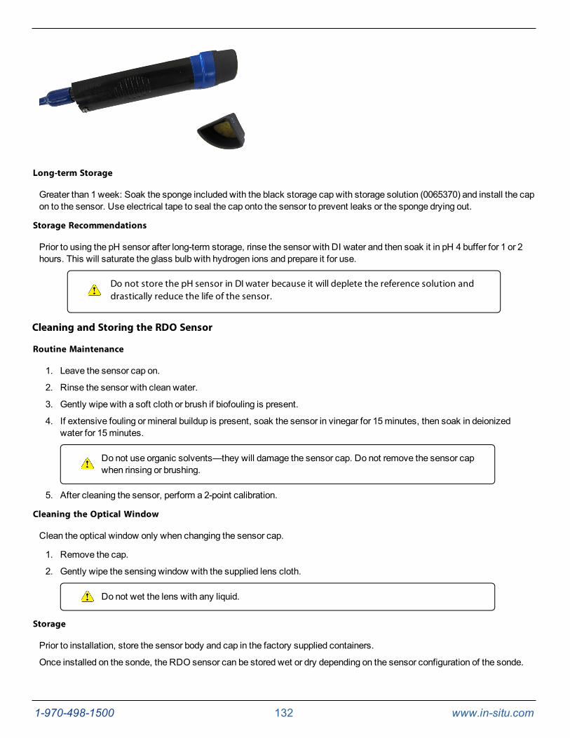
1-970-498-1500 132 www.in-situ.com
Long-term Storage
Greater than 1 week: Soak the sponge included with the black storage cap with storage solution (0065370) and install the capon to the sensor. Use electrical tape to seal the cap onto the sensor to prevent leaks or the sponge drying out.
Storage Recommendations
Prior to using the pH sensor after long-term storage, rinse the sensor with DI water and then soak it in pH 4 buffer for 1 or 2hours. This will saturate the glass bulb with hydrogen ions and prepare it for use.
Do not store the pH sensor in DI water because it will deplete the reference solution anddrastically reduce the life of the sensor.
Cleaning and Storing the RDO Sensor
Routine Maintenance
1. Leave the sensor cap on.
2. Rinse the sensor with clean water.
3. Gently wipe with a soft cloth or brush if biofouling is present.
4. If extensive fouling or mineral buildup is present, soak the sensor in vinegar for 15minutes, then soak in deionizedwater for 15minutes.
Do not use organic solvents—they will damage the sensor cap. Do not remove the sensor capwhen rinsing or brushing.
5. After cleaning the sensor, perform a 2-point calibration.
Cleaning the Optical Window
Clean the optical window only when changing the sensor cap.
1. Remove the cap.
2. Gently wipe the sensing window with the supplied lens cloth.
Do not wet the lens with any liquid.
Storage
Prior to installation, store the sensor body and cap in the factory supplied containers.
Once installed on the sonde, the RDO sensor can be stored wet or dry depending on the sensor configuration of the sonde.
1-970-498-1500 133 www.in-situ.com
Never store the RDO sensor without the sensor cap once it has been installed on thesonde.
Cleaning and Storing the Conductivity Sensor
Cleaning
Begin with themost gentle cleaningmethod and continue to the other methods only if necessary.
To clean the conductivity sensor face, gently rinse with clean, cold water. If further cleaning is required, consider the natureof the debris.
To remove crystalline deposits:
l Clean the sensor face with warm water andmild soap.
l Use a soft brush to gently clean the sensor pins and temperature button. Ensure removal of all debris around thebase of the pins and button.
l If crystalline deposits persist, soak in 5% HCl for 10 to 30minutes followed by warm soapy water and softbrushing.
l If deposits persist, alternate soaking in 5% HCl and 5% NaOH solutions followed by warm soapy water and softbrushing.
To remove oily or greasy residue:
l Clean the sensor face with warm water andmild soap.
l Using a soft brush, gently clean the sensor pins and temperature button. Ensure removal of all residue around thebase of the pins and temperature button.
l Isopropyl alcohol may be used for short soaking periods, up to one hour.
l Do not soak in strong solvents such as chlorinated solvents, ethers or ketones (such as acetone).
To remove protein-likematerial, or slimy film:
l Clean the sensor face with warm water andmild soap.
l Using a soft brush, gently clean the sensor pins and temperature button. Ensure removal of all material/film aroundthe base of the pins and temperature button.
l Soak the sensor in 0.10% HCl for 10minutes and then rinse thoroughly with distilled water.
Storage
Prior to installation, store the sensor in the factory supplied container.
Once installed on the sonde, the Temperature Sensor and Conductivity Sensor can be stored wet or dry depending on thesensor configuration of the sonde. For the best accuracy over instrument life, keep the conductivity cell submersed in waterfor 24-48 hours prior to calibration and deployment.
Cleaning and Storing the Turbidity Sensor
Routine Maintenance
The optical windows should be clear of foreignmaterial. To clear material gently rub the sensing windows using clean waterand a soft cloth or swab. Do not use solvents on the sensor.
Storage
Prior to installation, store the sensor in the factory supplied container.
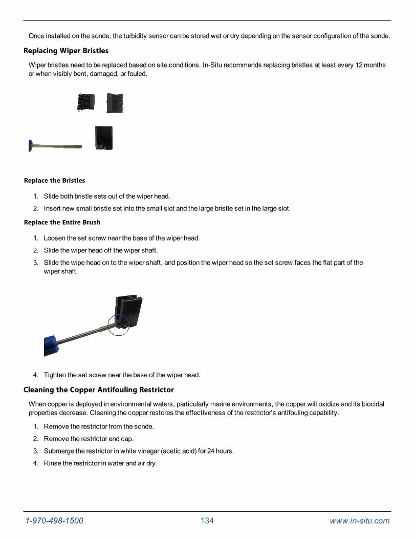
1-970-498-1500 134 www.in-situ.com
Once installed on the sonde, the turbidity sensor can be stored wet or dry depending on the sensor configuration of the sonde.
Replacing Wiper Bristles
Wiper bristles need to be replaced based on site conditions. In-Situ recommends replacing bristles at least every 12monthsor when visibly bent, damaged, or fouled.
Replace the Bristles
1. Slide both bristle sets out of the wiper head.
2. Insert new small bristle set into the small slot and the large bristle set in the large slot.
Replace the Entire Brush
1. Loosen the set screw near the base of the wiper head.
2. Slide the wiper head off the wiper shaft.
3. Slide the wipe head on to the wiper shaft, and position the wiper head so the set screw faces the flat part of thewiper shaft.
4. Tighten the set screw near the base of the wiper head.
Cleaning the Copper Antifouling Restrictor
When copper is deployed in environmental waters, particularly marine environments, the copper will oxidize and its biocidalproperties decrease. Cleaning the copper restores the effectiveness of the restrictor's antifouling capability.
1. Remove the restrictor from the sonde.
2. Remove the restrictor end cap.
3. Submerge the restrictor in white vinegar (acetic acid) for 24 hours.
4. Rinse the restrictor in water and air dry.
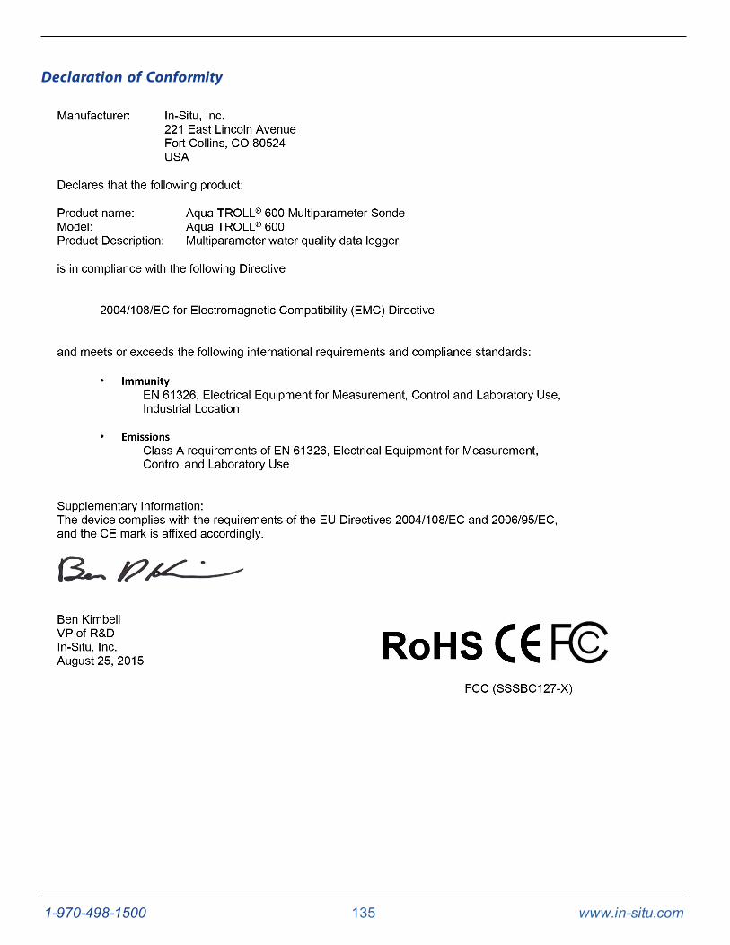
1-970-498-1500 135 www.in-situ.com
Declaration of Conformity
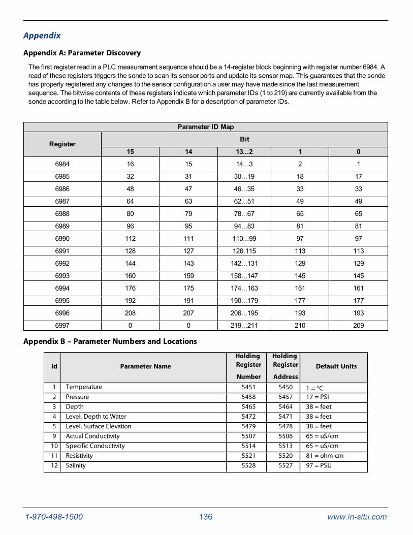
1-970-498-1500 136 www.in-situ.com
Appendix
Appendix A: Parameter Discovery
The first register read in a PLC measurement sequence should be a 14-register block beginning with register number 6984. Aread of these registers triggers the sonde to scan its sensor ports and update its sensor map. This guarantees that the sondehas properly registered any changes to the sensor configuration a user may havemade since the last measurementsequence. The bitwise contents of these registers indicate which parameter IDs (1 to 219) are currently available from thesonde according to the table below. Refer to Appendix B for a description of parameter IDs.
Parameter ID Map
Register Bit
15 14 13...2 1 0
6984 16 15 14...3 2 1
6985 32 31 30...19 18 17
6986 48 47 46...35 33 33
6987 64 63 62...51 49 49
6988 80 79 78...67 65 65
6989 96 95 94...83 81 81
6990 112 111 110...99 97 97
6991 128 127 126.115 113 113
6992 144 143 142...131 129 129
6993 160 159 158...147 145 145
6994 176 175 174...163 161 161
6995 192 191 190...179 177 177
6996 208 207 206...195 193 193
6997 0 0 219...211 210 209
Appendix B – Parameter Numbers and Locations
Id Parameter NameHoldingRegister
Number
HoldingRegister
AddressDefault Units
1 Temperature 5451 5450 1 = °C2 Pressure 5458 5457 17 = PSI3 Depth 5465 5464 38 = feet4 Level, Depth to Water 5472 5471 38 = feet5 Level, Surface Elevation 5479 5478 38 = feet9 Actual Conductivity 5507 5506 65 = uS/cm10 Specific Conductivity 5514 5513 65 = uS/cm11 Resistivity 5521 5520 81 = ohm-cm12 Salinity 5528 5527 97 = PSU
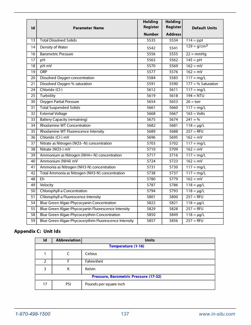
1-970-498-1500 137 www.in-situ.com
Id Parameter NameHoldingRegister
Number
HoldingRegister
AddressDefault Units
13 Total Dissolved Solids 5535 5534 114 = ppt
14 Density of Water 5542 5541 129 = g/cm3
16 Barometric Pressure 5556 5555 22 = mmHg17 pH 5563 5562 145 = pH18 pH mV 5570 5569 162 = mV19 ORP 5577 5576 162 = mV20 Dissolved Oxygen concentration 5584 5583 117 = mg/L21 Dissolved Oxygen % saturation 5591 5590 177 = % Saturation24 Chloride (Cl-) 5612 5611 117 = mg/L25 Turbidity 5619 5618 194 = NTU30 Oxygen Partial Pressure 5654 5653 26 = torr31 Total Suspended Solids 5661 5660 117 = mg/L32 External Voltage 5668 5667 163 = Volts33 Battery Capacity (remaining) 5675 5674 241 = %34 Rhodamine WT Concentration 5682 5681 118 = µg/L35 Rhodamine WT Fluorescence Intensity 5689 5688 257 = RFU36 Chloride (Cl-) mV 5696 5695 162 = mV37 Nitrate as Nitrogen (NO3--N) concentration 5703 5702 117 = mg/L38 Nitrate (NO3-) mV 5710 5709 162 = mV39 Ammonium as Nitrogen (NH4+-N) concentration 5717 5716 117 = mg/L40 Ammonium (NH4) mV 5724 5723 162 = mV41 Ammonia as Nitrogen (NH3-N) concentration 5731 5730 117 = mg/L42 Total Ammonia as Nitrogen (NH3-N) concentration 5738 5737 117 = mg/L48 Eh 5780 5779 162 = mV49 Velocity 5787 5786 118 = µg/L50 Chlorophyll-a Concentration 5794 5793 118 = µg/L51 Chlorophyll-a Fluorescence Intensity 5801 5800 257 = RFU54 Blue Green Algae-Phycocyanin Concentration 5822 5821 118 = µg/L55 Blue Green Algae-Phycocyanin Fluorescence Intensity 5829 5828 257 = RFU58 Blue Green Algae-Phycocerythrin Concentration 5850 5849 118 = µg/L59 Blue Green Algae-Phycocerythrin Fluorescence Intensity 5857 5856 257 = RFU
Appendix C: Unit Ids
Id Abbreviation UnitsTemperature (1-16)
1 C Celsius
2 F Fahrenheit
3 K Kelvin
Pressure, Barometric Pressure (17-32)
17 PSI Pounds per square inch
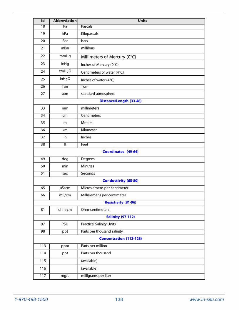
1-970-498-1500 138 www.in-situ.com
Id Abbreviation Units18 Pa Pascals
19 kPa Kilopascals
20 Bar bars
21 mBar millibars
22 mmHg Millimeters of Mercury (0°C)23 inHg Inches of Mercury (0°C)
24 cmH2O Centimeters of water (4°C)
25 inH2O Inches of water (4°C)
26 Torr Torr
27 atm standard atmosphere
Distance/Length (33-48)
33 mm millimeters
34 cm Centimeters
35 m Meters
36 km Kilometer
37 in Inches
38 ft Feet
Coordinates (49-64)
49 deg Degrees
50 min Minutes
51 sec Seconds
Conductivity (65-80)
65 uS/cm Microsiemens per centimeter
66 mS/cm Millisiemens per centimeter
Resistivity (81-96)
81 ohm-cm Ohm-centimeters
Salinity (97-112)
97 PSU Practical Salinity Units
98 ppt Parts per thousand salinity
Concentration (113-128)
113 ppm Parts per million
114 ppt Parts per thousand
115 (available)
116 (available)
117 mg/L milligrams per liter

1-970-498-1500 139 www.in-situ.com
Id Abbreviation Units
118 µg/L micrograms per liter
119 --- (deprecated, no longer available, was uM/L; was used but invalid)
120 g/L grams per liter
121 ppb Parts per billion
Density (129-144)
129 g/cm3 Grams per cubic centimeter
pH (145-160)
145 pH pH
Voltage (161-176)
161 µV micro Volts
162 mV milli Volts
163 V Volts
Dissolved Oxygen (DO) % Saturation (177-192)
177 % sat Percent saturation
Turbidity (193-208)
193 FNU formazin nephelometric units
194 NTU nephelometric turbidity units
195 FTU formazin turbidity units
Flow (209-224)
209 ft3/s Cubic feet per second
210 Available (was Cubic feet per minute)
211 Available (was Cubic feet per hour)
212 ft3/day Cubic feet per day
213 gal/s Gallons per second
214 gal/min Gallons per minute
215 gal/hr Gallons per hour
216 MGD Millions of gallons per day
217 m3/sec Cubic meters per second
218 Available (was Cubic meters per minute)
219 m3/hr Cubic meters per hour
220 Available (was Cubic meters per day)
221 L/s Liters per second
222 ML/day Millions of liters per day
223 mL/min milliliters per minute
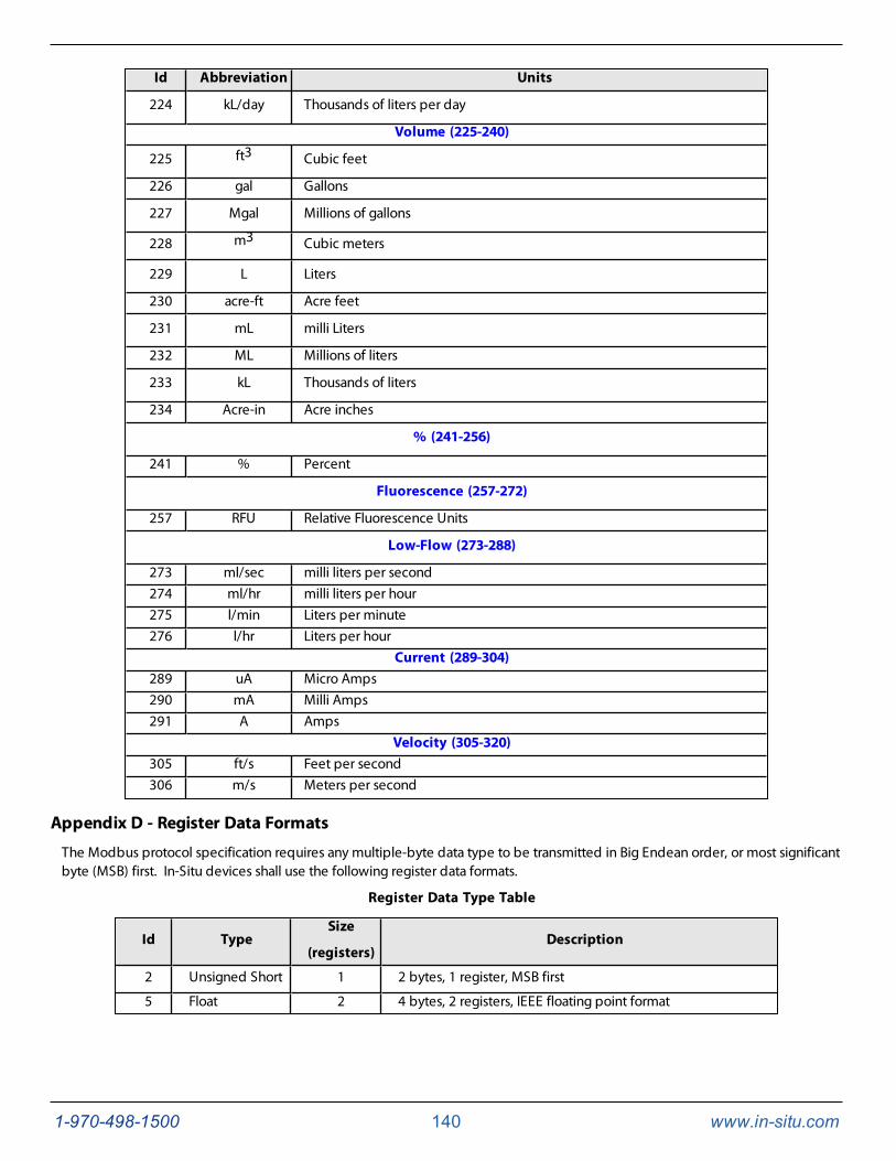
1-970-498-1500 140 www.in-situ.com
Id Abbreviation Units
224 kL/day Thousands of liters per day
Volume (225-240)
225 ft3 Cubic feet
226 gal Gallons
227 Mgal Millions of gallons
228 m3 Cubic meters
229 L Liters
230 acre-ft Acre feet
231 mL milli Liters
232 ML Millions of liters
233 kL Thousands of liters
234 Acre-in Acre inches
% (241-256)
241 % Percent
Fluorescence (257-272)
257 RFU Relative Fluorescence Units
Low-Flow (273-288)
273 ml/sec milli liters per second274 ml/hr milli liters per hour275 l/min Liters per minute276 l/hr Liters per hour
Current (289-304)289 uA Micro Amps290 mA Milli Amps291 A Amps
Velocity (305-320)305 ft/s Feet per second306 m/s Meters per second
Appendix D - Register Data Formats
The Modbus protocol specification requires any multiple-byte data type to be transmitted in Big Endean order, or most significantbyte (MSB) first. In-Situ devices shall use the following register data formats.
Register Data Type Table
Id TypeSize
(registers)Description
2 Unsigned Short 1 2 bytes, 1 register, MSB first
5 Float 2 4 bytes, 2 registers, IEEE floating point format

1-970-498-1500 141 www.in-situ.com
Related Documents