Automotive Visions of the Future: Automotive CFD Chemical Microreactors Take CFD to the Max Marine CFD Makes Waves in the America’s Cup Power NO x Busters Aerospace and Defense Supplement Inside! Dynamic Mesh VOL XI ISSUE 2 • FALL 2002 APPLIED COMPUTATIONAL FLUID DYNAMICS

Welcome message from author
This document is posted to help you gain knowledge. Please leave a comment to let me know what you think about it! Share it to your friends and learn new things together.
Transcript

AutomotiveVisions of the Future: Automotive CFD
ChemicalMicroreactors Take CFD to the Max
MarineCFD Makes Waves in the America’s Cup
PowerNOx Busters
Aerospace and DefenseSupplement Inside!
Dynamic Mesh
VOL XI ISSUE 2 • FALL 2002
A P P L I E D C O M P U T A T I O N A L F L U I D D Y N A M I C S

Contents
S4
16S11
applications
12 automotiveMotorscooter AerodynamicsBrake System Condensation Modeling
17 materialsAdvanced Multiphase Models from
SINTEF
18 chemicalMicroreactors Take CFD to the Max
20 marineCFD Makes Waves in the America’s CupThe Ongoing Success of EPFL
23 equipment manufacturersHigh Performance Compact Heat Exchangers
feature stories
5 dynamic mesh
The Dynamic Mesh Model
Vibromixers Take the Plunge
Store Separation Analysis
Powerful In-Cylinder CFD
24 power generationNOx BustersTrapped Vortex Combustors Show PromiseNuclear Reactor Accident Simulator
27 lightingLighting Up Plasma Lamps
28 environmentalJudgement Day for CFD Technology
29 hvacTaking the Heat Out of the Clinton Museum
30 glass and fibersDrawing Optical FibersOzone-Friendly Insulation
21
10
S12

27
5
39departments
12 visions of the futureAutomotive CFD
32 academic newsFlowLab Enters the Engineering CurriculumFluent Holds First Annual Student ContestPrestigious Award for Fluent Italy Employee
34 computingEngineering Simulation in the Next Decade
35 product newsWhat’s New in FLUENT 6.1Development News for POLYFLOW 3.10FIDAP 8.7 Scheduled for Fall 2002 ReleaseGAMBIT 2.1: A Breakthrough in CAD
Import
40 support cornerCAD Import & Cleanup in GAMBIT
42 partnershipsEASy!™ for Pumps Design Software Uses
Fluent TechnologygO:CFD Integrates FLUENT with gPROMS
for Reactive Flow ModelingFLUENT/RELAP5-3D© Integration Enters
Validation StageQNET – Building Quality and Trust in
Industrial CFDNAFEMS CFD Working Group
44 around FluentFluent Benelux Opens in Wavre, BelgiumIMechE Gives First-Ever Award for Software
to Fluent Europe
aerospace anddefense supplement
S2 overviewTaking CFD to New Heights in
the Aerospace Industry
S3 aviation safetyEuropean External Aerodynamics
Projects at INTAEnhancing Thrust Reverser
Performance
S5 electronicsFLUENT and Icepak Team Up for
Electronics Cooling Analysis
S6 wind tunnelsOver a Decade of FLUENT
Simulations at NASA Langley
S8 external aerodynamicsSmartFish?AIAA Drag Workshop RevisitedHellfire and Back
S10 defenseTank and Artillery Cannon Muzzle
Brakes – Reducing Gun RecoilQuietly
Dynamic Adaption in FLUENT 6.1
S12 fuel injectorsHigh Performance Fuel Injector
Design
Editor’s Note
Fluent News is published by
10 Cavendish CourtLebanon, NH 03766 USA
1-800-445-4454
© 2002 Fluent Inc. All rights reserved.
FLUENT, FIDAP, GAMBIT, POLYFLOW,G/Turbo, MixSim, FlowLab, Icepak,and Airpak are trademarks of Fluent
Inc. All other products or namebrands are trademarks of their
respective holders.
The ability to peerinto machinery inoperation has been
one of the leading ben-efits that CFD has offeredto engineers over theyears. The earliest sim-
ulations provided images of steady state conditions.These soon gave way to transient simulations thatcould follow time-dependent phenomena rang-ing from blending to vortex shedding to com-bustion instabilities. The introduction of the slidingmesh model in the early 1990s widened the fieldof view to include the flow associated with trainspassing in a tunnel and impellers rotating in abaffled tank.
With the dynamic mesh model in FLUENT 6.1,the opportunities to observe, understand, andlearn about complex fluid flow have expandedonce again. This model allows for the arbitrarymotion of fluid boundaries and in doing so, cap-tures the response of the fluid to the prescribedboundary motion. The number of applicationsthat can benefit from this exciting new capabilityabound, and include in-cylinder analysis, storeseparation, moving valves, and mixing equip-ment. On the pages that follow, we are pleasedto present a technical summary of the dynam-ic mesh model, and several companion articlesthat illustrate how the model can be put to use.
Even with a static mesh, there is still muchto be learned from the other application storiesthat appear in this issue. A story from Japan onmicroreactors explains how new technology willchange the way chemicals are produced in thefuture. A French manufacturer of optical fibersmakes a clear case that the quality of the fin-ished product is highly sensitive to the flow sur-rounding the fiber throughout the entireprocess. An American producer of insulationdescribes how efforts are underway to use mate-
rials that have little or no impact on our envi-ronment. And with the America’s Cup races fastapproaching, we learn how the Swiss are usingCFD to understand several wind- and water-relat-ed phenomena that have a powerful impact ona vessel under sail.
The supplement in this issue focuses on theAerospace Industry, and features an impressivearray of applications. Safety issues are a commontheme in a few of the stories. For example, thetrailing vortices off airplane wing tips are the sub-ject of an investigation by a Spanish research organ-ization, and the performance of thrust reversersis of interest to an American aircraft manufac-turer. The dispersion of exhaust gases from mis-siles launched from an Apache helicopter is shownto be yet another area where CFD can be usedto assess potential danger. A unique simulationis also presented in which means of suppress-ing artillery noise is examined using some of themost sophisticated grid adaption techniques everdeployed.
In addition to the departments normally appear-ing in Fluent News, we introduce something newwith this issue: interviews with influential peo-ple whose organizations have been at the fore-front of CFD use within a particular industry. Ourfirst interview is with MIRA’s Anthony Baxendale,who gives his opinions on how CFD might beused within the automotive industry in the future.
We hope that you find this issue of Fluent Newsinteresting and informative. Please send us yourfeedback, and tell us about how our softwarehas helped you.
On the Supplement Cover:The dynamic mesh model in FLUENTis used to simulate the release of astore from a CFD model of a deltawing; oil film lines are used toillustrate the flow around the storeat two times after the release
On the Cover:Pathlines are used to illustrate the swirling flow in neighboringcylinders at two piston positions ina Deutz BF4M 1011F diesel engine;the dynamic mesh model in FLUENTwas used for the simulation Courtesy of Deutz AG

Fluent NEWS fall 2002 5
dynamic mesh
Introduced as a beta feature in FLUENT 6.0, the dynamic meshmodel, part of the moving and
deforming mesh capability, extendsthe capacity of the FLUENT solver to handle problems that involveunsteady moving geometry. After successfully completing severalindustrial strength test cases, and fea-turing several enhancements, thedynamic mesh model is being for-mally released to all users in FLUENT6.1. In addition to significant robust-ness improvements, the model willbe fully parallelized.
In order to accommodate awide range of motion types, FLUENT6 offers three modes of mesh defor-mation: dynamic layering, springsmoothing, and local remeshing. Thefirst two approaches are similar tomesh motion schemes that have beenwidely used for many years. Dynamiclayering is useful for linear motion.
Layers are added and deleted toaccommodate the specified bound-ary motion. The term “dynamic”means that the process is handledinternally by the FLUENT solver, basedonly on a specified ideal cell height,and factors that govern when a cellshould split and when two shouldcoalesce. These parameters defineupper and lower cell height limits.When the cell height limits are exceed-ed, FLUENT automatically detects thiscondition, and splits or coalesces thelayer as needed. Because cells areadded and deleted, neighbor con-nectivity changes are made as well.This approach may be utilized forquadrilateral (2D volume cells and3D boundary faces), prismatic, andhexahedral element types.
The spring smoothing method isuseful for relatively small deformations.The assumption in FLUENT is that themesh nodes are connected like a net-
The DynamicMesh Model
By Jerry Lim, Fluent Inc.
Pressure contours on a 3D valve
Valve motion shown in two steps above; below, the first step is shown incyan (light blue) the second is overlayed in magenta, and grey denotes nochange to the mesh between the steps
6 Fluent NEWS fall 2002
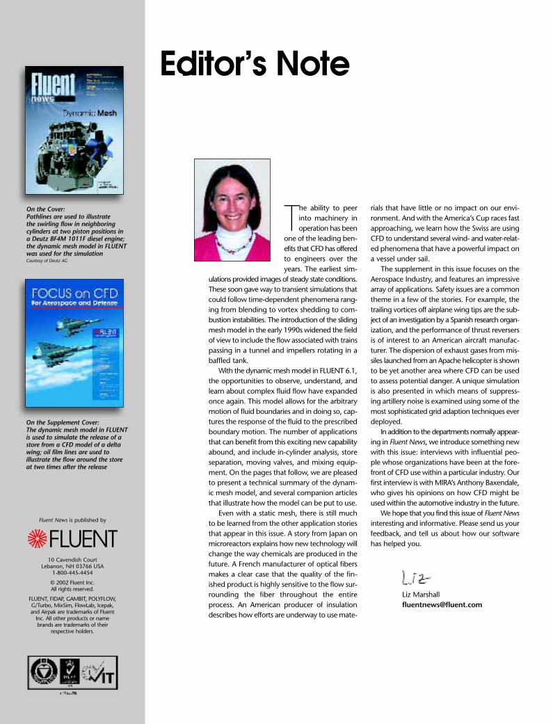
work of springs. By performing a forcebalance on each of the “spring ele-ments”, an equilibrium balance issought which provides a smooth (min-imum energy) mesh. If two elements(nodes) are too close, the spring forcewill repel the nodes away from eachother. Since each nodal positiondepends on its neighbor nodes, andthe neighbor nodal positions aredependent on their own neighbornodes, spring smoothing is accom-plished through an iterative process,like that used by other elliptic meshgenerators. The spring smoothingprocess does not result in any con-nectivity changes since all node/cellrelationships are preserved. Used asa stand-alone scheme, spring smooth-ing is limited, since excessive defor-mation will result in highly skewedcells. The spring smoothing algorithmmay be used for triangular (2D vol-ume cells, 3D boundary faces) andtetrahedral elements.
The third approach, local remesh-ing, represents a departure from tra-ditional mesh motion schemes. In thisapproach, the cell size and quality(skewness) limits are prescribed. Asmesh motion occurs, cells will even-tually exceed the prescribed limits. FLUENT detects these cells andmarks them for remeshing. In addi-
tion to marking the offending cells,several neighbor cells are also marked.This collection of cells represents a sub-domain, which is automaticallyremeshed using the TGrid algorithmthat is now built into FLUENT. Afterremeshing, the CFD solution is inter-polated onto the new cells. Thus, ratherthan generate a completely new mesh for the entire volume, remesh-ing and interpolation works on a localbasis. As with dynamic layering, localremeshing implies connectivitychanges. Typically (but not necessarily),it is used in conjunction with springsmoothing. The local remeshingalgorithm may be used for triangu-lar (2D volume cells, 3D boundary faces) and tetrahedral elements.
A dynamic calculation requires aninitial mesh and description of theboundary motion. A model with sev-eral independently moving parts canbe treated using different zones to represent the different parts. In-dependent motions for these partscan be specified, and the regions surrounding them will be remeshedusing whichever technique is appro-priate at the time. The flexibility ofthe model makes it well suited toaddress a number of different appli-cation areas, as described in the articles that follow. ■
dynamic mesh
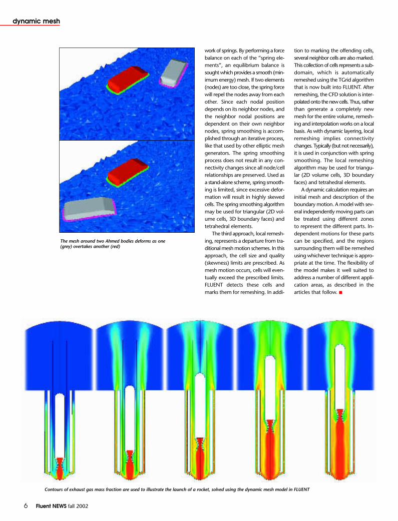
Contours of exhaust gas mass fraction are used to illustrate the launch of a rocket, solved using the dynamic mesh model in FLUENT
The mesh around two Ahmed bodies deforms as one (grey) overtakes another (red)

Fluent NEWS fall 2002 7
dynamic mesh
Disk impellers that agitate a liquid by moving upand down are called vibromixers. These impellersusually contain conical perforations through the
disk, but some varieties function without them.Vibromixers provide some interesting advantages overconventional impellers for certain applications. For bio-chemical reactors, such as fermenters, it has been shownthat vibromixers can generate mass transfer coefficientsthat are substantially higher than those obtained in a rotationally stirred reactor.1 In the pharmaceutical indus-try, where microscopic solids in suspension need to bemaintained in sterilized, hermetically sealed containers,vibromixers provide a good alternative to stirred tanks.They are more portable, use a simpler motor mount,and don’t require a rotating seal.
The dynamic mesh model in FLUENT 6 was recent-ly used to simulate a vibromixer operating in a vesselof water. The disk has over forty perforations that arein the shape of truncated cones. When the disk under-goes periodic motion through the fluid, jets are repeat-edly forced out the tapered ends of these perforations,due to the venturi effect. Over time, these jets give riseto large circulation patterns in the tank, which is impor-tant for good turbulent mixing. Depending on the orientation of the conical perforations, the design canbe used for both up-pumping and down-pumping applications.
A 650,000 cell mesh of unstructured hexahedral ele-ments was used for the simulation. Using Coopering toolsin GAMBIT, quad cells were created on the disk surfaceand extruded in the axial direction to build the volumemesh. This process created even layers of hexahedra,which is an excellent mesh environment for the antic-ipated disk motion. User defined functions were usedto specify the time dependent velocity of the disk, anda new grid was created automatically at each time stepusing the dynamic layering algorithm. During this process,the cells near the disk were either stretched or contracted,or an entire layer was added or removed to adjust toeach new disk position.
Because the tapered ends of the perforations are ori-ented upwards, jets are emitted from the tops of theholes during the downward stroke of the impeller. Thesejets can be captured by drawing iso-surfaces of constantvelocity magnitude. During the upward stroke, fluid flowsin the reverse direction into diverging conical volumes.Jets formed as the fluid passes into these volumes throughthe tapered ends are weak, and they quickly dissipate.After the vibromixer has been operating for several cycles,pathlines can be used to illustrate the circulation pat-terns that have developed in the surrounding fluid. ■
1 Ni, X., Gao, S., Cumming, R. H., and Pritchard, D.W, AComparative Study of Mass Transfer in Yeast for a BatchPulsed Baffled Bioreactor and a Stirred Tank Fermenter, Chem. Eng. Sci. 50:2127-2136, 1995.
Pathlines colored by timeillustrate the circulation patternsgenerated by the mixer
VibromixersTake The
PLUNGEBy Kumar M. Dhanasekharan and Srinivasa L. Mohan, Fluent Inc.
Iso-surfaces of velocity magnitude illustrate the jetsemanating from the holes

8 Fluent NEWS fall 2002
dynamic mesh
One of the most challengingproblems in aerospaceengineering, especially for
military vehicles, is the analysis ofa store (a weapon, fuel tank, or elec-tronic countermeasures device, for example) that is released froma high-speed aircraft. Store separa-tion analysis typically includes such things as a calculation of thetrajectory, the identification of safeseparation zones, an assessment ofaerodynamic interference, and mak-ing sure that collisions are avoided.For multiple separations, typical ofcluster bombs for example, the analy-sis could also include the dispersioncharacteristics of the weapon, so thatthe munitions cover the biggest pos-sible area upon impact with theground.
For many years, physical testingusing the actual aircraft and devicehas been the only method for per-forming store separation analysis. Thecost and risks associated with suchtests can be high, however, espe-cially during parametric studies. Thedynamic mesh model in FLUENT nowprovides a safer, more cost-effective solution to the analysis needs of aero-space companies involved in this kindof application.
The basic characteristic of storeseparation analysis is the presenceof a body that moves in the com-putational domain as a result of its
interaction with the computedflow field. This means that in addi-tion to the need for a dynamic mesh,tools are also required that deter-mine the body movement based onthe local flow conditions. These toolsneed to accurately compute the aero-dynamic forces on the body, anddetermine the dynamic response ofthe body to these forces. A trajec-tory calculation is performed to inte-grate the forces and moments onthe body, and provide an accurateposition of the body as a functionof time.
The most challenging of thesetasks, by far, is the mesh handling.The geometric complexity of mod-ern aircraft and the stores, which maybe outfitted with fins, guidancedevices or release mechanisms,necessitates the use of complex mesh-es, comprised mostly of tetrahedralelements. The remeshing schemesneed to be robust and deliver highquality meshes that can be relied uponfor accurate aerodynamic load pre-dictions at each time step. Since thou-sands of time steps may be neededfor an accurate analysis, depend-ing on such factors as the releasespeed or aircraft speed, the meshhandling also needs to be done ina time-efficient manner.
For the store separation simula-tion shown at left, a user-defined func-tion (UDF) is used to compute the
Store Separation
AnalysisBy Evangelos K. Koutsavdis, Fluent Inc.
The evolution of the grid for a 2D storeseparation simulation
Fluent NEWS fall 2002 9
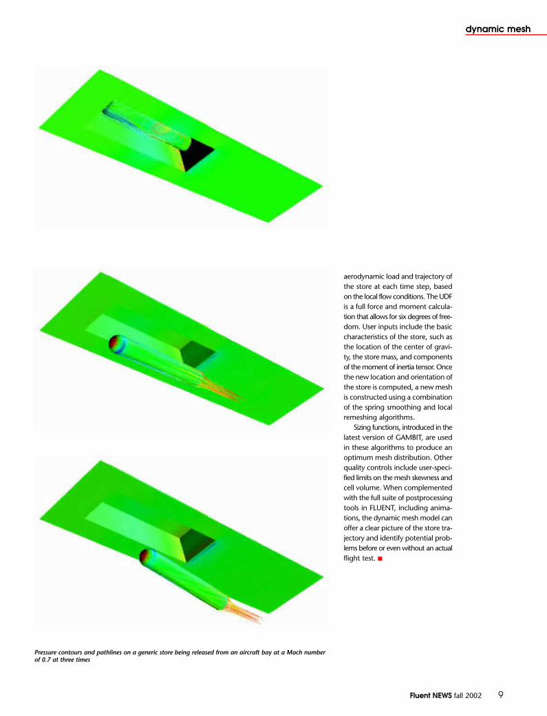
Pressure contours and pathlines on a generic store being released from an aircraft bay at a Mach numberof 0.7 at three times
dynamic mesh
aerodynamic load and trajectory ofthe store at each time step, basedon the local flow conditions. The UDFis a full force and moment calcula-tion that allows for six degrees of free-dom. User inputs include the basiccharacteristics of the store, such asthe location of the center of gravi-ty, the store mass, and componentsof the moment of inertia tensor. Oncethe new location and orientation ofthe store is computed, a new meshis constructed using a combinationof the spring smoothing and localremeshing algorithms.
Sizing functions, introduced in thelatest version of GAMBIT, are usedin these algorithms to produce anoptimum mesh distribution. Otherquality controls include user-speci-fied limits on the mesh skewness andcell volume. When complementedwith the full suite of postprocessingtools in FLUENT, including anima-tions, the dynamic mesh model canoffer a clear picture of the store tra-jectory and identify potential prob-lems before or even without an actual flight test. ■
10 Fluent NEWS fall 2002
dynamic mesh
The simulation of internal combustion engineswith moving pistons and valves is one of thepremier applications of the dynamic mesh
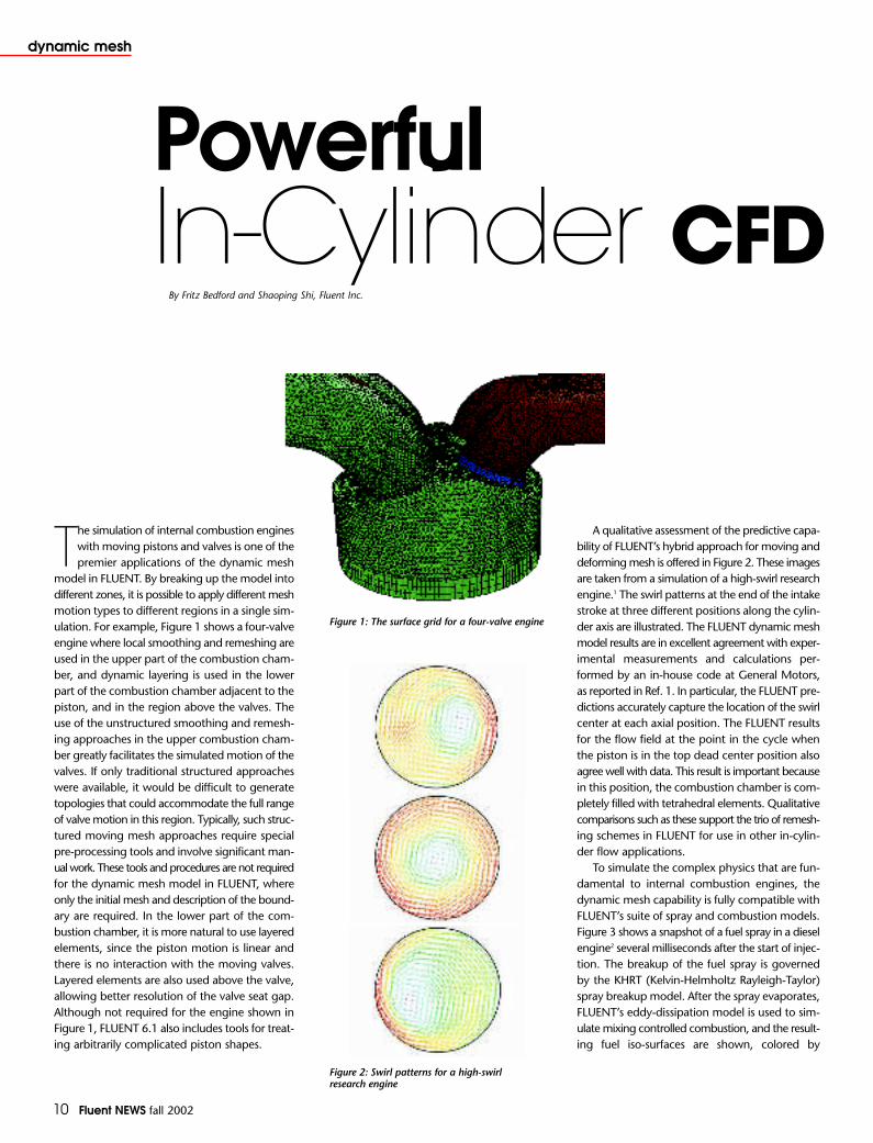
model in FLUENT. By breaking up the model intodifferent zones, it is possible to apply different meshmotion types to different regions in a single sim-ulation. For example, Figure 1 shows a four-valveengine where local smoothing and remeshing areused in the upper part of the combustion cham-ber, and dynamic layering is used in the lowerpart of the combustion chamber adjacent to thepiston, and in the region above the valves. Theuse of the unstructured smoothing and remesh-ing approaches in the upper combustion cham-ber greatly facilitates the simulated motion of thevalves. If only traditional structured approacheswere available, it would be difficult to generatetopologies that could accommodate the full rangeof valve motion in this region. Typically, such struc-tured moving mesh approaches require specialpre-processing tools and involve significant man-ual work. These tools and procedures are not requiredfor the dynamic mesh model in FLUENT, whereonly the initial mesh and description of the bound-ary are required. In the lower part of the com-bustion chamber, it is more natural to use layeredelements, since the piston motion is linear andthere is no interaction with the moving valves.Layered elements are also used above the valve,allowing better resolution of the valve seat gap.Although not required for the engine shown inFigure 1, FLUENT 6.1 also includes tools for treat-ing arbitrarily complicated piston shapes.
Powerful In-Cylinder CFD
By Fritz Bedford and Shaoping Shi, Fluent Inc.
Figure 1: The surface grid for a four-valve engine
Figure 2: Swirl patterns for a high-swirlresearch engine
A qualitative assessment of the predictive capa-bility of FLUENT’s hybrid approach for moving anddeforming mesh is offered in Figure 2. These imagesare taken from a simulation of a high-swirl researchengine.1 The swirl patterns at the end of the intakestroke at three different positions along the cylin-der axis are illustrated. The FLUENT dynamic meshmodel results are in excellent agreement with exper-imental measurements and calculations per-formed by an in-house code at General Motors,as reported in Ref. 1. In particular, the FLUENT pre-dictions accurately capture the location of the swirlcenter at each axial position. The FLUENT resultsfor the flow field at the point in the cycle whenthe piston is in the top dead center position alsoagree well with data. This result is important becausein this position, the combustion chamber is com-pletely filled with tetrahedral elements. Qualitativecomparisons such as these support the trio of remesh-ing schemes in FLUENT for use in other in-cylin-der flow applications.
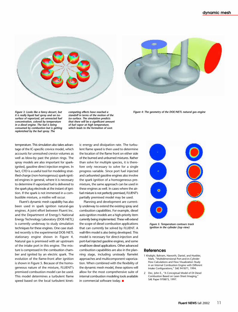
To simulate the complex physics that are fun-damental to internal combustion engines, the dynamic mesh capability is fully compatible withFLUENT’s suite of spray and combustion models.Figure 3 shows a snapshot of a fuel spray in a dieselengine2 several milliseconds after the start of injec-tion. The breakup of the fuel spray is governedby the KHRT (Kelvin-Helmholtz Rayleigh-Taylor)spray breakup model. After the spray evaporates,FLUENT’s eddy-dissipation model is used to sim-ulate mixing controlled combustion, and the result-ing fuel iso-surfaces are shown, colored by
Fluent NEWS fall 2002 11
dynamic mesh
Figure 3: Looks like a fancy dessert, butit is really liquid fuel spray and an iso-surface of vaporized, yet unreacted fuelconcentration, colored by temperaturein a diesel engine. The fuel is beingconsumed by combustion but is gettingreplenished by the fuel spray. The
competing effects have reached astandoff in terms of the motion of theiso-surface. The simulation predictsthat there will be a significant amountof fuel vapor at high temperature,which leads to the formation of soot.
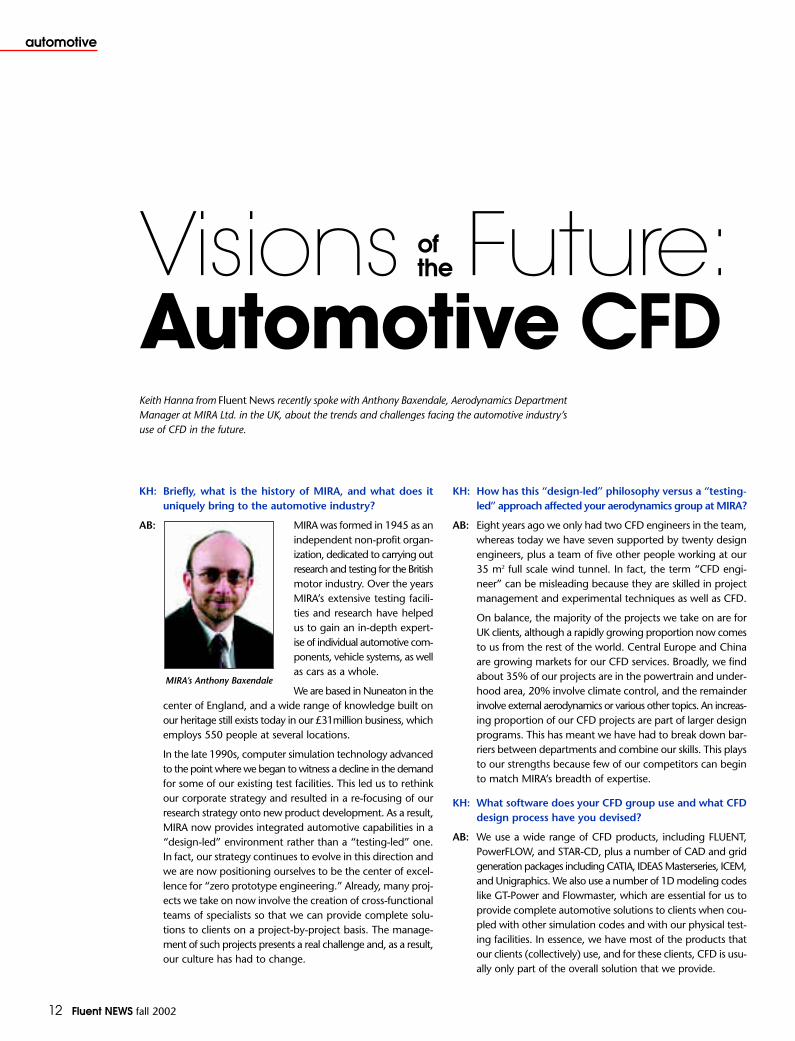
Figure 4: The geometry of the DOE/NETL natural gas engine
Figure 5: Temperature contours trackignition in the cylinder (top view)
temperature. This simulation also takes advan-tage of the IC-specific crevice model, whichaccounts for unresolved crevice volumes aswell as blow-by past the piston rings. Thespray models are also important for spark-ignited, gasoline direct injection engines. Infact, CFD is a useful tool for modeling strat-ified-charge (non-homogenous) spark-ignit-ed engines in general, where it is necessaryto determine if vaporized fuel is delivered tothe spark plug electrode at the instant of igni-tion. If the spark is not immersed in a com-bustible mixture, a misfire will occur.
Fluent’s dynamic mesh capability has alsobeen used in spark ignition natural-gasengines. A joint effort between Fluent Inc.and the Department of Energy’s NationalEnergy Technology Laboratory (DOE-NETL)is currently underway to study simulationtechniques for these engines. One case stud-ied recently is the experimental DOE-NETLstationary engine shown in Figure 4.Natural gas is premixed with air upstreamof the intake port in this engine. The mix-ture is compressed in the combustion cham-ber and ignited by an electric spark. Theevolution of the flame-front after ignitionis shown in Figure 5. Because of the homo-geneous nature of the mixture, FLUENT’spremixed combustion model can be used.This model determines a turbulent flamespeed based on the local turbulent kinet-
ic energy and dissipation rate. The turbu-lent flame speed is then used to determinethe location of the flame front on either sideof the burned and unburned mixtures. Ratherthan solve for multiple species, it is there-fore only necessary to solve for a singleprogress variable. Since port fuel injectedand carbureted gasoline engines also involvethe spark ignition of a homogeneous pre-mixture, the same approach can be used inthese engines as well. In cases where the air-fuel mixture is not perfectly premixed, FLUENT’spartially premixed model may be used.
Planning and development are current-ly underway to extend the existing spray andcombustion capabilities. For example, dieselauto-ignition models are a high-priority itemcurrently being implemented. These will extendthe scope of diesel combustion applicationsthat can currently be solved by FLUENT. Awall-film model is also being developed. Thismodel is necessary for direct-injection andport-fuel injected gasoline engines, and somesmall-bore diesel applications. Other advancedcombustion capabilities are also in the plan-ning stage, including unsteady flameletapproaches and multicomponent vaporiza-tion. When combined with the flexibility ofthe dynamic mesh model, these options willallow for the most comprehensive suite ofinternal combustion modeling tools availablein commercial software today. ■
References1 Khalighi, Bahram, Haworth, Daniel, and Huebler,
Mark, “Multidimensional Port-and-in-CylinderFlow Calculations and Flow Visualization Studyin an Internal Combustion Engine with DifferentIntake Configurations,” SAE 941871, 1994.
2 Dec, John E., “A Conceptual Model of DI DieselCombustion Based on Laser-Sheet Imaging,”SAE Paper 970873, 1997.
12 Fluent NEWS fall 2002
automotive
KH: Briefly, what is the history of MIRA, and what does it uniquely bring to the automotive industry?
MIRA was formed in 1945 as anindependent non-profit organ-ization, dedicated to carrying outresearch and testing for the Britishmotor industry. Over the yearsMIRA’s extensive testing facili-ties and research have helpedus to gain an in-depth expert-ise of individual automotive com-ponents, vehicle systems, as wellas cars as a whole.
We are based in Nuneaton in thecenter of England, and a wide range of knowledge built onour heritage still exists today in our £31million business, whichemploys 550 people at several locations.
In the late 1990s, computer simulation technology advancedto the point where we began to witness a decline in the demandfor some of our existing test facilities. This led us to rethinkour corporate strategy and resulted in a re-focusing of ourresearch strategy onto new product development. As a result,MIRA now provides integrated automotive capabilities in a“design-led” environment rather than a “testing-led” one.In fact, our strategy continues to evolve in this direction andwe are now positioning ourselves to be the center of excel-lence for “zero prototype engineering.” Already, many proj-ects we take on now involve the creation of cross-functionalteams of specialists so that we can provide complete solu-tions to clients on a project-by-project basis. The manage-ment of such projects presents a real challenge and, as a result,our culture has had to change.
KH: How has this “design-led” philosophy versus a “testing-led” approach affected your aerodynamics group at MIRA?
AB: Eight years ago we only had two CFD engineers in the team,whereas today we have seven supported by twenty designengineers, plus a team of five other people working at our35 m2 full scale wind tunnel. In fact, the term “CFD engi-neer” can be misleading because they are skilled in projectmanagement and experimental techniques as well as CFD.
On balance, the majority of the projects we take on are forUK clients, although a rapidly growing proportion now comesto us from the rest of the world. Central Europe and Chinaare growing markets for our CFD services. Broadly, we findabout 35% of our projects are in the powertrain and under-hood area, 20% involve climate control, and the remainderinvolve external aerodynamics or various other topics. An increas-ing proportion of our CFD projects are part of larger designprograms. This has meant we have had to break down bar-riers between departments and combine our skills. This playsto our strengths because few of our competitors can beginto match MIRA’s breadth of expertise.
KH: What software does your CFD group use and what CFDdesign process have you devised?
AB: We use a wide range of CFD products, including FLUENT,PowerFLOW, and STAR-CD, plus a number of CAD and gridgeneration packages including CATIA, IDEAS Masterseries, ICEM,and Unigraphics. We also use a number of 1D modeling codeslike GT-Power and Flowmaster, which are essential for us toprovide complete automotive solutions to clients when cou-pled with other simulation codes and with our physical test-ing facilities. In essence, we have most of the products thatour clients (collectively) use, and for these clients, CFD is usu-ally only part of the overall solution that we provide.
Visions Future:Automotive CFDKeith Hanna from Fluent News recently spoke with Anthony Baxendale, Aerodynamics DepartmentManager at MIRA Ltd. in the UK, about the trends and challenges facing the automotive industry’suse of CFD in the future.
AB:
MIRA’s Anthony Baxendale
of the

Fluent NEWS fall 2002 13
automotive
Like many users of CFD in the automotive industry we useCAD geometries that are either given to us or that we cre-ate ourselves. Indeed, “dirty” CAD geometries and their clean-up can take between 10 and 60% of a project’s total time.Hence, we find it helps to educate our CAD engineers on whatmakes for good geometry requirements from a CFD perspective.Basically, they must work on a design with CFD in mind, althoughthis has to be balanced with the need to design with man-ufacturing in mind. This is a significant paradigm shift thatneeds to happen for CFD users and the CFD industry as well.
Although we use commercial software, we are developingsome pretty clever processes to cut meshing times and tointegrate solution methodologies. We see this as innovationand as part of increasing our competitive advantage. For exam-ple, this is happening in the areas of thermal managementand unsteady aerodynamics. We will be promoting our newcapabilities in these and other areas very soon.
A strong part of our CFD process is employing the latest proj-ect management systems and scheduling software to com-plete projects on time and on budget. Historically, we haveused large UNIX workstations for our CFD processing, butlately we have shifted towards PC’s because of their reducedcost per processor, their expanding power, and the abilityto network clusters of them together. Indeed, Fluent’s soft-ware has the best parallel portability to PC clusters we haveseen (on both LINUX and Windows operating systems).
As we looked at our CFD process over the last few years toevaluate savings and cost reductions, we identified the needto consolidate our software and hardware to work with keysuppliers like Fluent to develop long term relationships toour mutual benefit. Today our typical CFD simulations rangebetween 5 and 15 million cells, although we expect this torise to over 25 million in the next year.
Pathlines over a Mazda MX5Geometry obtained via www.viewpoint.com
Concept/Targets• Marketing• Engineering Capability• Business Case
Traditional Vehicle Development Process
Concept Development• Packaging• Mules/Prototypes
Design• Detailing
Validation• Soft-Tool Prototypes• Detail Design Update
Maturation• Tooling Installation• Certification Tests
Volume
Concept/Targets• Marketing• Engineering Capability• Business Case
Virtual Prototyping
Design• Detailing
Volume
Virtual Prototype Development Process Time Saved
Validation• Tooling Installation• Off-Tool Tests

automotive
14 Fluent NEWS fall 2002
KH: FLUENT is a relative newcomer to the group of CFD codes used atMIRA. What factors led to your recent investment in this software?
AB: We chose the FLUENT CFD software as it offers a wide range of func-tionality, is easy to use, and is robust. Another factor in our decisionwas that the FLUENT code is requested by many of our major clients,primarily those in the automotive industry.
KH: Five years from now, where do you foresee CFD being positionedwithin the automotive industry?
AB: Three or four years ago we saw a sudden mushrooming of the use ofCFD in the automotive industry as it moved out of the research anddevelopment departments and into the design process. I see a con-tinued rapid growth in the use of CFD, although there are some sig-nificant process barriers to overcome. In five years’ time or less, I caneasily see full vehicle CFD models with underhood, climate control,and external aerodynamics all in one model, developed in a day andrun in an hour! Indeed, I foresee that other simulations will be cou-pled to the CFD models and computed concurrently. Almost certain-ly, time-dependent simulations will become more routine, and I expectto see large strides in CFD’s integration into the overall design process.There will be steady improvements in software accuracy and usabili-ty, and the use of web-based CFD will be more common both with-in a company and across sites worldwide.
KH: Finally, what do you see as the challenges for the CFD industry inmeeting the needs of the automotive community in the long term?
AB: For a start, integrating CFD into the design process will be critical aspart of “digital vehicle prototyping.” Companies like Jaguar think inthese terms and have digital “gateways” in the automotive productdevelopment cycle within a common simulation environment. I believethat such an environment will join together “best-in-class” softwareproducts with expert systems software and common data manage-ment structures. We need to develop organizational learning skills aswe go along so we can manage risk and fill gaps in our knowledgeand processes quickly.
Another big area for the future is what we call “co-simulation” where,for example, in the field of aero-acoustics, automotive CFD aerody-namics departments will predict noise levels for a given automotivedesign. This data will then be fed into a Structures Code to see howthe noise interacts with the vehicle’s body. Ergonomics software willbe used to register how this noise will be perceived inside the car. Therewill, therefore, be a need for the right links between different softwaretechnologies such as these.
In terms of CFD advances, I can easily foresee a growth in demandfor large-eddy simulation (LES) modeling in CFD, and improved tur-bulence models for more accurate predictions. This is naturally so becauseall real-world flows are inherently unsteady anyway. In the future, thebest hardware and CFD software on the market will have to meet theseautomotive market demands.
It is my belief that at the end of the day, CFD engineers will use thebest available tools from a toolbox to make assessments and judgmentson a given engineering design. I see CFD purely as an engineeringtool. Engineers will, therefore, want to choose a reliable yet easy-to-use CFD tool that can deliver accurate results quickly. That is the bot-tom line. It is also important for engineers to be able to view their CFDpredictions and interrogate them easily. I foresee that with cheaperhardware and advances in both virtual reality technology and elec-tronic reporting, we will be presenting and viewing our results verydifferently in the years to come.
Looking beyond the near future and beyond usage by CFD engineers,there are some interesting options to ponder. Will we be using CFDin actual cars to do real-time, customized simulations of climate con-trol to improve occupant comfort, for instance? Will we be giving ver-bal commands to computers to do on-the-fly CFD simulations and comeup with multiple predictions so that we can exercise our engineeringjudgment on the spot? Now, that would be something! Whatever hap-pens, I foresee a rosy but challenging future for CFD in the automo-tive industry. ■
european automotive CFD conference 2003Fluent is pleased to announcethe first conference for appliedCFD users in the Europeanautomotive industry.
Bingen, Germany June 25-26, 2003
• Future directions of applied CFD• Virtual prototyping• Keynote speeches• Sessions for automotive CFD applications• Leading hardware and software innovations• Leading practitioners in applied CFD• Latest developments in America and Japan• Social Program
For more information and to register:www.fluent.com/support/ugm/index.htm
Courtesy of Ferrari
Fluent NEWS fall 2002 15
automotive
Motorcycle aerodynamics doesn’tusually receive as much attentionas that for automobiles. This is
partly because the automobile is more wide-ly used as a method of transportation, andpartly because the aerodynamics of a motor-cycle changes as the rider shifts position.Furthermore, because the wheels of a motor-cycle are only partially shielded, it is diffi-cult to realize a fully streamlined body foreither simulation or testing purposes.
To date, many motorcycle components,such as the frame and shock absorbers, havebeen physically tested and numerically sim-ulated. These components have a power-ful influence on vehicle handling, safety, andperformance. External aerodynamics, onthe other hand, affects fuel consumption,vehicle stability and handling, and rider andpassenger comfort. To a lesser degree, theexternal airflow affects engine and brakecooling. Taken together, it is clear that exter-nal aerodynamics plays a significant roleon the overall performance of the bike.
At the University of Perugia in Perugia,Italy, simulations performed using FLUENThave recently been carried out on a com-mercial motorscooter. As a first step in this
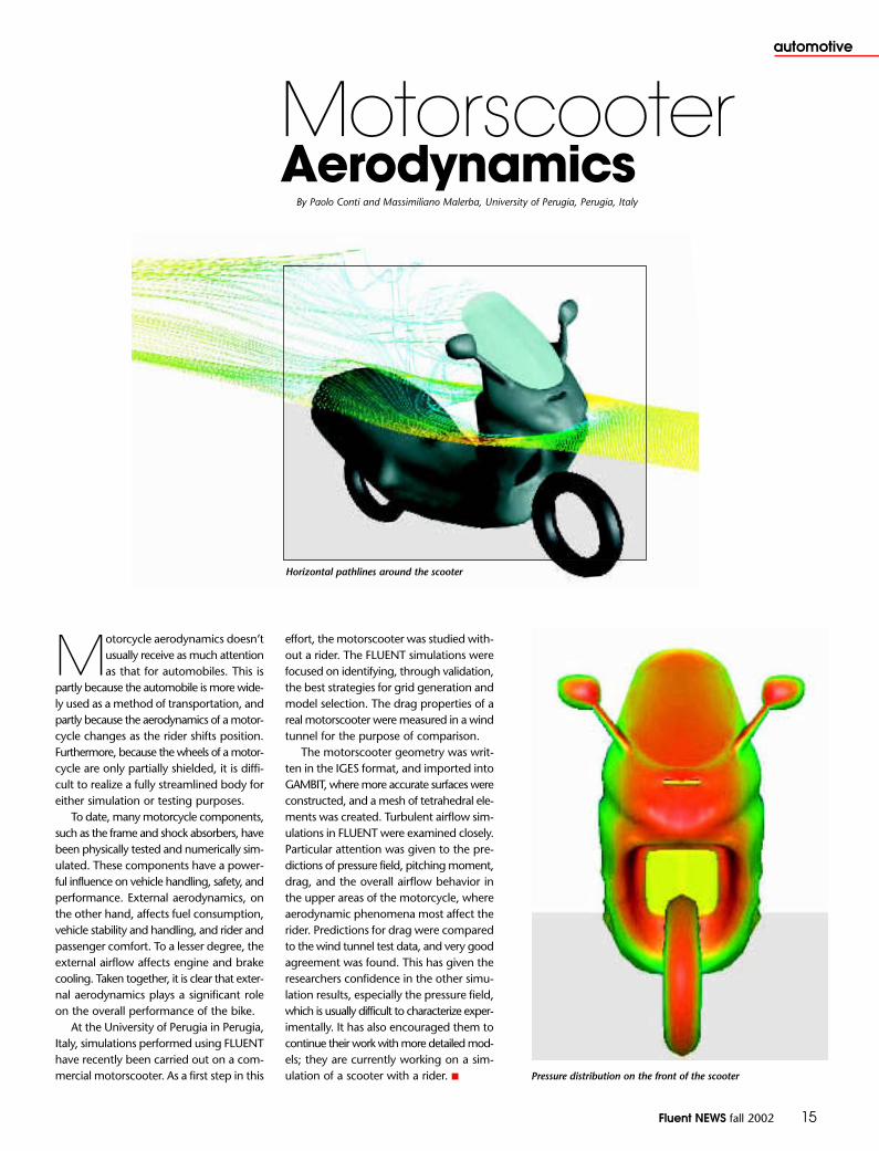
effort, the motorscooter was studied with-out a rider. The FLUENT simulations werefocused on identifying, through validation,the best strategies for grid generation andmodel selection. The drag properties of areal motorscooter were measured in a windtunnel for the purpose of comparison.
The motorscooter geometry was writ-ten in the IGES format, and imported intoGAMBIT, where more accurate surfaces wereconstructed, and a mesh of tetrahedral ele-ments was created. Turbulent airflow sim-ulations in FLUENT were examined closely.Particular attention was given to the pre-dictions of pressure field, pitching moment,drag, and the overall airflow behavior inthe upper areas of the motorcycle, whereaerodynamic phenomena most affect therider. Predictions for drag were comparedto the wind tunnel test data, and very goodagreement was found. This has given theresearchers confidence in the other simu-lation results, especially the pressure field,which is usually difficult to characterize exper-imentally. It has also encouraged them tocontinue their work with more detailed mod-els; they are currently working on a sim-ulation of a scooter with a rider. ■
Horizontal pathlines around the scooter
Pressure distribution on the front of the scooter
MotorscooterAerodynamics
By Paolo Conti and Massimiliano Malerba, University of Perugia, Perugia, Italy
16 Fluent NEWS fall 2002
automotive
Earlier this year, WABCO Automotive UK Ltd., a lead-ing manufacturer of innovative automotive com-ponents, tasked Fluent Europe with comparing the
efficiency of their current air dryer unit against a newdesign. The unit is positioned downstream of a com-mercial vehicle compressor, and is designed to removewater from the air before it enters the brake system.
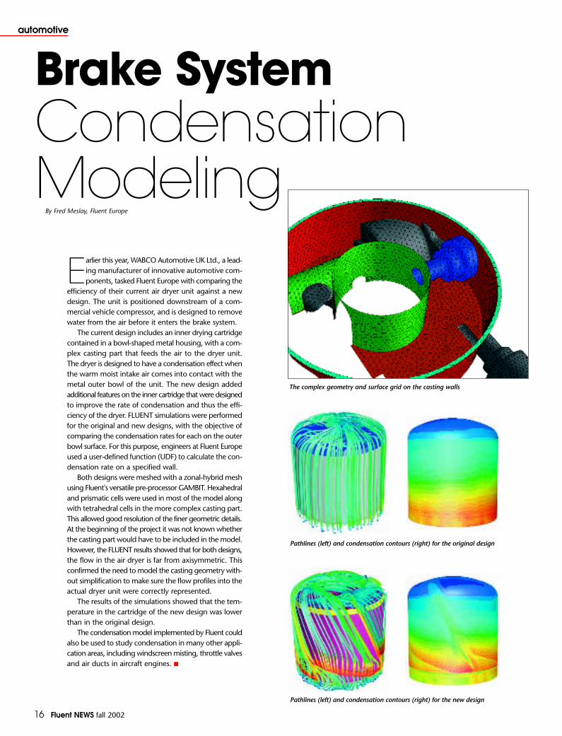
The current design includes an inner drying cartridgecontained in a bowl-shaped metal housing, with a com-plex casting part that feeds the air to the dryer unit.The dryer is designed to have a condensation effect whenthe warm moist intake air comes into contact with themetal outer bowl of the unit. The new design addedadditional features on the inner cartridge that were designedto improve the rate of condensation and thus the effi-ciency of the dryer. FLUENT simulations were performedfor the original and new designs, with the objective ofcomparing the condensation rates for each on the outerbowl surface. For this purpose, engineers at Fluent Europeused a user-defined function (UDF) to calculate the con-densation rate on a specified wall.
Both designs were meshed with a zonal-hybrid meshusing Fluent's versatile pre-processor GAMBIT. Hexahedraland prismatic cells were used in most of the model alongwith tetrahedral cells in the more complex casting part.This allowed good resolution of the finer geometric details.At the beginning of the project it was not known whetherthe casting part would have to be included in the model.However, the FLUENT results showed that for both designs,the flow in the air dryer is far from axisymmetric. Thisconfirmed the need to model the casting geometry with-out simplification to make sure the flow profiles into theactual dryer unit were correctly represented.
The results of the simulations showed that the tem-perature in the cartridge of the new design was lowerthan in the original design.
The condensation model implemented by Fluent couldalso be used to study condensation in many other appli-cation areas, including windscreen misting, throttle valvesand air ducts in aircraft engines. ■
Brake SystemCondensationModeling
By Fred Meslay, Fluent Europe
Pathlines (left) and condensation contours (right) for the original design
Pathlines (left) and condensation contours (right) for the new design
The complex geometry and surface grid on the casting walls

Fluent NEWS fall 2002 17
materials
SINTEF Materials Technology has used Fluent software to improvemetallurgical and chemical processes since 1985. In 2001,Fluent and SINTEF formalized their long-standing relation-
ship via a partnership agreement, under which SINTEF may devel-op and deliver modeling enhancements to Fluent clients. Thecooperation provides Fluent clients improved access to SINTEF’sexpertise and to new models, developed under non-commercialresearch projects, that improve the prediction of combustion, pol-lutant formation, radiation, solidification, magnetohydrodynam-ics, electrochemistry, and multiphase flows encountered in themetallurgical and oil/gas industries.
“SINTEF was a pioneer in multiphase CFD modeling, devel-oping Eulerian multifluid modeling of gas-solid flows as early as1988 using FLUENT 2.97,” says Stein Tore Johansen, Research Directorof the Department of Flow Technology at SINTEF. “In coopera-tion with the ferro-alloy and incineration industries, we are nowextending the capacity for detailed modeling of reactive flows,in particular with respect to NOx and pyrolysis.”
Recently, design studies of ferrosilicon plants were performed.The project began with a combustion simulation in FLUENT ofthe old furnace hood and off-gas channel at an Elkem ferrosili-con plant. FLUENT was then used to support the design of a newoff-gas system that fulfills Elkem’s requirements for plant opera-tion performance. With the new off-gas system, the furnace is nowoperating at higher loads, the clogging danger is considerablyreduced, gas leakages from the hood to the environment are pre-vented, and the new cooling system is able to recover severalGWhs/year of electric energy.
SINTEF has also developed within FLUENT advanced solidifi-cation models for metallurgical applications, based on the multi-fluid approach. Macrosegregation, or variations in compositionduring solidification caused by melt convection and moving crys-tals, can be simulated with these tools. The solidification routinesare coupled to micromodels for the growth kinetics of dendrites,branch-like structures formed by nonuniformities in the melt.
During the last decades, the Norwegian aluminum industry hasfocused heavily on increased current efficiency and improved energy efficiency in reduction cells, used for aluminum processing.Quantitative knowledge of the flow pattern in the liquid metal andelectrolyte of aluminum reduction cells has been important for guid-ing the performance improvements. Engineers at SINTEF implementeda solver for the electromagnetic field in early versions of FLUENT,enabling the study of magnetohydrodynamic flow in these cells.During the last two years, electrochemical models have been addedto FLUENT and combined with a mixture multiphase flow modelto produce a special code for electrolysis cell design.
Bubbly flows occurring in metallurgical applications have alsobeen a focus of research and development at SINTEF. Recently,FLUENT has been used to calculate mixing in a gas-stirred ladlefor steel alloying and particle flotation for cleaning molten metal.Based on models for coalescence and break-up, a transport equa-tion for the mean bubble size in turbulent flow has been devel-oped within FLUENT. Bubble sizes in stirred flows have been measuredin the department’s water model laboratory, and are now usedfor CFD model validation. Simulation of bubbly flows and freesurfaces guided SINTEF during analysis of operational problemsthat occurred in the fermenter loop at Norferm’s bioprotein plant.Using FLUENT, SINTEF and Norferm developed a new separatorvessel, allowing the gas produced by the bacteria to escape beforethe flow entered the pump. ■
[email protected]/units/matek
Pathlines in an old design of the furnacehood and the off-gas channels of aferrosilicon plant; at the base of thefurnace, contours of temperature areplotted on an iso-surface of constantreaction rate
Prediction of flow in aluminumelectrolysis cells, showing gasconcentration, lines of constantelectric potential, and velocityvectors in the electrolyte
The final macrosegregation percentage in a fully solidified Sn-5wt%Pballoy, which was solidified by cooling at the left hand wall; the mixturewas depleted of lead at the top surface and enriched with it at thebottom; red regions have the highest positive macrosegregation, orhighest lead content; blue regions have the highest negativemacrosegregation, or lowest lead content
AdvancedMultiphaseModels from SINTEF
By Knut Bech and Harald Laux, SINTEF, Trondheim, Norway

18 Fluent NEWS fall 2002
chemical
Microreactors Take CFD to the
MAXBy Ken-Ichiro Sotowa, and Katsuki Kusakabe,Department of Applied Chemistry, Kyushu University, Japan;and David Street, Fluent Asia Pacific In recent years there has been an
increased interest throughoutJapan in the research and devel-
opment of microreactors. During thistime, the Japanese government,through three MITI (Ministry ofInternational Trade and Industry)national projects, has committed near-ly 10 million US dollars to the wide-spread investigation of these uniquedevices. Leading the research effortare several prominent Japanese uni-versities, including Tokyo University,Kyoto University, The Tokyo Instituteof Technology, and Kyushu University.Many leading Japanese chemical com-panies are also participating in thisimportant long-term national project.
Microreactors, as the name implies,are very small chemical reactors. Theyare typically only a few centimeterslong and the channels throughwhich the fluids flow are on the orderof 10 to 100 microns in diameter. Thereactors themselves are made usingmaterials such as silicon, quartz, poly-mers, and metals that have well-definedphysical and chemical properties. Theyare manufactured using micro-fab-rication techniques developed in thefields of microelectronics and MEMS(micro-electro-mechanical systems)engineering. The reactor manufacturingprocesses may therefore involvephotolithography, etching, and thinfilm deposition to build the flow chan-nels, micro-heaters, and variousmicro-sensors. Micromilling has beenused for the fabrication of certainmicroscale structures. Microscalepumps, driven by gears or piezoelectricdevices, have also been developed.Some of these microfluidic devices arenot much bigger than the head of
a ball-point pen, but they can be effec-tively used to drive the flow throughthe tiny microreactor channels.
There are numerous applicationsfor microreactors, ranging from bio-medical diagnostic devices to cat-alytic gas phase reactors operatingat elevated temperatures. There isconsiderable interest in the use ofmicroreactors for the production ofon-demand hydrogen for fuel cells,and on-demand drug production anddelivery. In fact, some of theresearch into the more far-reachingapplications of microreactors isgoing on behind closed doors, intop-secret programs at some ofJapan’s largest and most well-respected companies.
There are several reasons why somuch effort is being devoted to devel-op such tiny reactors with such lim-ited production capacities. Becauseof their size, it is possible to constructa chemical plant consisting ofmicroreactors that is small enoughto be moved from place to place.In the future, portable plants will beused as the primary workhorses inthe distributed production of chem-icals, in which chemicals are producedat the point of consumption. In addi-tion to providing on-demand pro-duction of hydrogen for fuel cells,these plants will be used for on-siteproduction of hazardous chemicals,which currently incur considerablerisk to humans, animals, and the envi-ronment when transported onroads or rails. Another advantage ofmicroreactors is the high surface areato volume ratio that can be achievedwith tiny channel sizes. This makesit easier to control the fluid tem-
A microreactor fabricated on a silicon substrate(sealed with a glass plate) at Kyushu University

Fluent NEWS fall 2002 19
chemical
Schematic representation of amicroreactor contacting device
Experimental observation of mixing at a Y-junction(channel width=400 micrometers)
Simulated concentration profiles in the two-fluid stream
perature, which is an importantparameter influencing reaction rateand selectivity. In addition, appro-priate arrangement of the microchan-nels makes it possible to attainmicroscale mixing of two fluids almostinstantaneously.
CFD has been widely used to bet-ter understand microreactor flowsand help design ways to improvetheir efficiency. For example, veloc-ities through a single microreactorchip are typically in the range of afew milliliters per second. Toincrease the throughput and makethe devices commercially viable, manychannels can be used together inparallel. In an effort to design head-ers for dividing the flow uniformlyamong the channels, some researchgroups have developed bifurcatingchannels, similar in principle to thehuman lung, whereas others have
developed simpler, open headers withporous regions or baffles to createmore uniform flow. In both cases,CFD is being used to aid in the design.It is also being used to determinethe residence time distribution(RTD) through microreactor chan-nels. Whereas large scale reactorstypically operate in the turbulentregime, the flow inside a microre-actor is usually laminar. Without tur-bulent eddies, very tight control overthe residence time distribution canbe achieved, so that the reactor con-ditions can be well understood. CFDoffers one of the quickest and eas-iest ways to determine RTD for sim-ple or complex channel designs.
At Kyushu University, FLUENT hasrecently been used to investigatemicroreactors that work with immis-cible fluids. Using the volume of fluid(VOF) model, a small bubble of hexa-
ne (oil) is injected into a flowing aque-ous stream. The oil bubble growsin size and eventually breaks awayfrom the oil inlet stream. Conventionalchemical engineering modelingapproaches assume that mass trans-fer from the bubble of hexane tothe bulk fluid is purely by diffusion.By contrast, the FLUENT results suggest that there is considerableconvective mass transport occur-ring as well. This mechanism dra-matically enhances mass transfer bymore than a factor of 100.
In another project, two streamsare brought into direct contact as theyflow side-by-side through a microre-actor. When these streams – solutionsof sodium hydroxide (NaOH) and BTB,a ph-indicator – are brought into closecontact, a BTB-alkali reaction takesplace at the interface, even thoughthe fluids are miscible with each other.
This is because of the laminarnature of the flow in microchannels.FLUENT predictions of the distribu-tion of NaOH concentration have beenfound to agree well with experimentalresults. In some applications, it is nec-essary to enhance the mixing rateof two fluids by disturbing the inter-face. For these applications, CFD canbe used to study the channel struc-ture, which effectively disturbs theinterface and improves the mixing.
Simulations like these are just two examples of the considerableresearch effort currently beingdirected at microreactor applications.Many other areas in this growingfield are being investigated using CFD, since it can provide engineersand scientists with a cost effectivetechnological advantage in theirattempt to understand these impor-tant devices. ■
Flow patterns within an oil bubble injected into an aqueous stream
mass transfer

20 Fluent NEWS fall 2002
marine
Match racing trials of Alinghi boats inAuckland (Photo by Ph. Schiller / Alinghi)
CFD Makes
Waves in the
America’s Cup By Geoffrey W. Cowles, Nicola Parolini, Modeling and Scientific Computing,
Ecole Polytechnique Fédérale de Lausanne, Switzerland;and Mark L. Sawley, Granulair Technologies, Lausanne, Switzerland

Fluent NEWS fall 2002 21
marine
America’s Cup yacht racing has,over the past 150 years,proved to be a formidable
testing ground. To challenge the bestin this field, a high standard of tech-nological knowledge and innovationhas become essential. The engage-ment of the Ecole PolytechniqueFédérale de Lausanne (EPFL) as OfficialScientific Advisor to the AlinghiChallenge for the 2003 America’sCup, has provided the EPFL with theopportunity to continue its effortsin the numerical flow simulation ofhigh-performance racing yachts.
Resolving the mathematicalequations governing the flowaround an International America’sCup Class (IACC) boat is complicatedby the complex physical modelingrequired to account for hydrodynamicand aerodynamic flows, wave gen-eration on the water surface, andfluid-structure interaction with themast and sails. While “potential flow”methods are extensively used, toobtain a competitive edge in an appli-cation area where small performancedifferences can result in significantgains, it is important to account formore complex flow behavior.Solving the Reynolds-Averaged
Navier-Stokes (RANS) equationsprovides detailed insights that – whencombined with standard numericalmethods, experimental testing,empirical techniques and experience– can suggest ways to improve boatperformance.
At the EPFL, FLUENT is used tocompute both hydrodynamic andaerodynamic flows around theboat. Mesh generation is general-ly undertaken using GAMBIT. In closecollaboration with the AlinghiDesign Team, detailed numerical stud-ies are being performed in three prin-ciple areas: hydrodynamic flowaround the boat appendages, aero-dynamic flow around the mast andsails, and the generation of waveson the water surface. By calculat-ing the pathlines, surface pressure,and global forces on the boat, thebasic physical phenomena can bequalitatively and quantitativelyexamined.
Numerical flow simulations arebeing conducted for different bulb-keel-winglet configurations in orderto determine the shape with the leastdrag (within the applied constraintsof weight, structural strength, andlift). Such a study performed for a
“To have a realistic hope of winning the America’sCup, we need to excel in many areas. That’s the reason the partnership with the EcolePolytechnique Fédérale de Lausanne (EPFL) is soimportant to us. The EPFL’s academic expertisehelps us to validate ideas quickly in broad fieldssuch as material resistance, structural integrity,aero- and hydrodynamics, etc. In particular, the results of computational fluid dynamicssimulations have provided Alinghi with essentialinformation necessary for optimal design choice.”
Grant Simmer, Coordinator of the Alinghi Design Team
Surface pressure and pathlines around the appendages
Waves generated on the water surface by a Wigley hull
Under the direction of Grant Simmer, the coordinator of the Alinghi Design Team,two new boats have been designed and constructed for the 2003 America’sCup race. This has been the result of a Team project, involving all twelve ofAlinghi’s designers, researchers from the EPFL, and many Alinghi sailors.
22 Fluent NEWS fall 2002
marine
variety of sailing conditions requiresnot only numerous detailed simulationsbut also a significant effort in ana-lyzing the results.
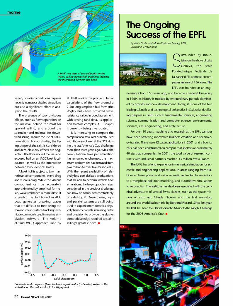
The presence of strong viscouseffects, such as flow separation onthe mainsail behind the mast forupwind sailing, and around the spinnaker and mainsail for down-wind sailing, require the use of RANSsimulations. For our studies, the fly-ing shape of the sails is consideredand aero-elasticity effects are neg-lected. The flow around the sails andexposed hull on an IACC boat is cal-culated, as well as the interactionbetween two identical boats.
A boat hull is subject to two mainresistance components: wave dragand viscous drag. While the viscouscomponent can be accuratelyapproximated by empirical formu-lae, wave resistance is more difficultto predict. The blunt bow of an IACCboat generates breaking wavesthat are difficult to treat using themoving-mesh surface-tracking tech-nique commonly used in marine sim-ulation software. The volume of fluid (VOF) approach used by
FLUENT avoids this problem. Initialcalculations of the flow around a2.5m long simplified hull form (theWigley hull) have provided waveresistance values in good agreementwith towing tank data. Its applica-tion to more complex IACC shapesis currently being investigated.
It is interesting to compare thecomputational resources currently usedwith those employed at the EPFL dur-ing the last America’s Cup challengemore than three years ago. While thecomputational time per simulationhas remained unchanged, the max-imum problem size has increased fromtwo million to over five million cells.With the recent availability of rela-tively low-cost desktop workstationsthat are able to perform sizeable flowsimulations, the largest problem sizesconsidered in the previous challengecan now be computed comfortablyon a desktop PC. Nevertheless, high-end parallel systems are still beingused to explore more complex phys-ical phenomena with increasing detailand precision to provide the elusivecompetitive edge required to claimsailing’s greatest prize. ■
A bird’s-eye view of two sailboats on thewater, sailing downwind; pathlines indicatethe interaction between the boats
The Ongoing Success of the EPFL
By Alain Drotz and Marie-Christine Sawley, EPFL, Lausanne, Switzerland
Surrounded by moun-
tains on the shore of Lake
Geneva, the Ecole
Polytechnique Fédérale de
Lausanne (EPFL) campus encom-
passes an area of 136 acres. The
EPFL was founded as an engi-
neering school 150 years ago, and became a Federal University
in 1969. Its history is marked by extraordinary periods dominat-
ed by growth and new development. Today, it is one of the two
leading scientific and technological universities in Switzerland, offer-
ing degrees in fields such as fundamental sciences, engineering
science, communication and computer science, environmental
sciences, civil engineering, and architecture.
For over 10 years, teaching and research at the EPFL campus
have been fostering innovative business creation and technolo-
gy transfer. There were 42 patent applications in 2001, and a Science
Park has been constructed on campus that shelters approximately
40 start-up companies. In 2001, the total value of research con-
tracts with industrial partners reached 33 million Swiss Francs.
The EPFL has a long experience in numerical simulation for sci-
entific and engineering applications, in areas ranging from tur-
bines to plasma physics and fusion, atomistic and molecular simulations
to atmospheric pollution modeling, and automotive simulations
to aeronautics. The Institute has also been associated with the tech-
nical adventures of several Swiss citizens, such as the space mis-
sion of astronaut Claude Nicolier and the first non-stop,
around-the-world balloon trip by Bertrand Piccard. Since last year,
the EPFL has been the Official Scientific Advisor to the Alinghi Challenge
for the 2003 America’s Cup. ■
Comparison of computed (blue line) and experimental (red circles) values of thewaterline on the surface of a 2.5m Wigley hull

aer
osp
ace
ind
ustry
aer
osp
ace
ind
ustryFOCUS on CFD
For Aerospace and DefenseFOCUS on CFDFor Aerospace and Defense
Newsletter Supplement
S2 overviewTaking CFD to New Heights in
the Aerospace Industry
S3 aviation safetyEuropean External Aerodynamics
Projects at INTAEnhancing Thrust Reverser
Performance
S5 electronicsFLUENT and Icepak Team Up for
Electronics Cooling Analysis
S6 wind tunnelsOver a Decade of FLUENT
Simulations at NASA Langley
S8 external aerodynamicsSmartFish?AIAA Drag Workshop RevisitedHellfire and Back
S10 defenseTank and Artillery Cannon Muzzle
Brakes – Reducing Gun RecoilQuietly
Dynamic Adaption in FLUENT 6.1
S12 fuel injectorsHigh Performance Fuel Injector
Design

Taking CFD to New Heightsin the Aerospace Industry
By Greg Stuckert, US Aerospace Industry Director
S2 Fluent NEWS fall 2002
overviewa
eros
pa
ce in
dus
trya
eros
pa
ce in
dus
try
Computational fluid dynamics has a longand illustrious history of developmentand use in the aerospace industry. Indeed,
many engineers associate CFD with its well-knownapplication to aerodynamics, namely the calculationof the lifting force on a wing. However, as meth-ods and resources have increased in power andease-of-use, practitioners have expanded the scopeof application beyond the calculation of lift. Today,CFD helps engineers predict not only lift, butalso variational changes in aerodynamic drag –generally, a much more challenging task.Fluent is also finding applications to many dif-ficult operational problems that, in the past, weretoo unwieldy to analyze with computational tools.
In this supplement, we present a small sam-pling of interesting applications of FLUENT toaerodynamic design and to the resolution of com-plex operational problems:
• The impact of trailing vortices on thesafe operation of successive aircrafttaking-off and landing on a runway;
• The prediction of the total lift and dragon a transonic wing-body configurationtested in several wind-tunnels;
• The design and analysis of a novelaerodynamic configuration similar tothat of a blended wing-body;
• The proper installation of engines on thewings of an aircraft to avoid problemsarising from the operation of thrustreversers;
• The safe operation of a militaryhelicopter upon firing a missile whoseplume could impinge on the airframe orthe tail rotor;
• The packaging of electronic componentsand control unit motors to provide asuitable thermal environment andensure reliable operation;
• The optimization of liquid fuel nozzlesused in the aerospace and powergeneration industries; and
• Efforts to understand and suppress thenoise produced by heavy artillery.
In addition, we are pleased to offer a sum-mary of more than a decade of FLUENT use atNASA Langley in Hampton, Virginia. Over theyears, work on the high-enthalpy wind tunnelat NASA Langley, used to test high altitude propul-sion systems and the behavior of structural andthermal protection system components, has rangedin scope from combustion to hypersonic flow.
Fluent has enabled the solution of these challenging problems by providing the toolsand technical support needed to simultaneouslymodel complex geometries and physics.Descriptions of many other challenging prob-lems can be found on our web site atwww.fluent.com/solutions/aerospace/index.htm.If you have used FLUENT in a creative and innovative way, please contact us at [email protected]. ■
“ATK Thiokol Propulsionengineers have successfullyused FLUENT in a variety ofanalyses that support safeand reliable design andoperation of the ATK familyof solid propellant rocketmotors. Ranging from thesmall-scale study of gas flowin joint gaps with widths thatare a fraction of an inch, tothe analysis of internal motorflow fields with scales on theorder of several feet, FLUENToffers a proven and reliablemethod for characterizingflow environments andproviding heat transfer andstructural load boundaryconditions for componentdesigners.”
Andrew M. Eaton, Ph.D. Supervisor, Gas Dynamics Section
ATK Thiokol Propulsion, USA
Pressure coefficient contours on the surface andvorticity magnitude contours on axial slices for amissile outfitted with grid fins, flying at Mach 1.5with a 10° canard (front wing) deflection and a 4°angle of attack. The vorticity contours illustrate thelocation of the canard trailing vortices. Whenplanar fins are used at this Mach number andangle of attack, these vortices interact with the finsand give rise to an adverse rolling moment for themissile. The missile roll is reduced when grid finsare used instead of planar fins, because thevortices are broken up as they interact with thegrid fin structure. The flow visualization was doneusing EnSight from Computational EngineeringInternational (CEI).Courtesy of US Army Research Laboratory
European ExternalAerodynamicsProjects at INTA
By Fernando Monge, INTA, Madrid, Spain
Fluent NEWS fall 2002 S3
aer
osp
ace
ind
ustry
aer
osp
ace
ind
ustry
aviation safety
The fluid dynamics area of INTA (InstitutoNacional de Tecnica Aeroespacial) has partici-pated in a number of European aeronautical proj-
ects during the past several years, and has used FLUENTas a part of this work. Other CFD codes have beenused in the projects as well, and a great deal of exper-imental data has been made available to scientistsand engineers. Together, the project challenges, alongwith the wealth of information shared by the par-ticipants, have allowed INTA to realize FLUENT’s poten-tial for several important applications.
The C-WAKE European project is one example.Coordinated by DaimlerChrysler Aerospace Airbus inBremen, Germany, the goal of the project is to char-acterize and control vortex wakes generated by pas-senger aircraft. These wakes are of particular interestduring take-off and landing maneuvers at busy airportswhen other aircraft are nearby, and during in-flightperiods on heavily traveled routes when the horizon-tal and vertical spacing limits between aircraft are inquestion. The timing between take-offs and landingshas been established at commercial airports for max-imum safety, but heavy air traffic has made increaseddemands on these guidelines. With this in mind, theC-WAKE project has focused on estimating the opti-mum separation between aircraft for in-flight condi-tions and on airport runways. It has also focused ondeveloping designs for new planes that generate re-duced vortex wakes, so that reductions in aircraft sep-aration can be considered. For this project, FLUENThas been used to calculate wakes from simplified air-plane geometries. The CFD results will be compared withexperimental data extracted from wind tunnel tests.
INTA is also applying FLUENT to the developmentof second-generation supersonic passenger carriers. Thesecarriers are being investigated in response to increaseddemand for long distance flights with the desire to haveshorter flight times. While these aircraft will undoubt-edly meet the performance goals of longer distancesin shorter times, they also must meet strict environ-mental guidelines and comply with stringent noise emis-sion regulations. The European Project for Improvementof Supersonic Transport Low Speed Efficiency, or EPIS-TLE, is a group of European aircraft manufacturers andresearchers who have joined forces to investigate theflight characteristics of these carriers in the low speedregime, in conditions typical of take-off and landing.One focus is on high lift devices near the leading edgeof the wings that cause controlled flow separation,enhanced lift, but significant additional drag. The goalis to develop novel designs for these devices, test theiroperating characteristics when used with delta wingplanes, and validate the findings against wind tunneldata. FLUENT simulations are currently being run tostudy high lift devices that allow an increase of 15 –20% in the aerodynamic efficiency of supersonic air-craft flying at low speed.
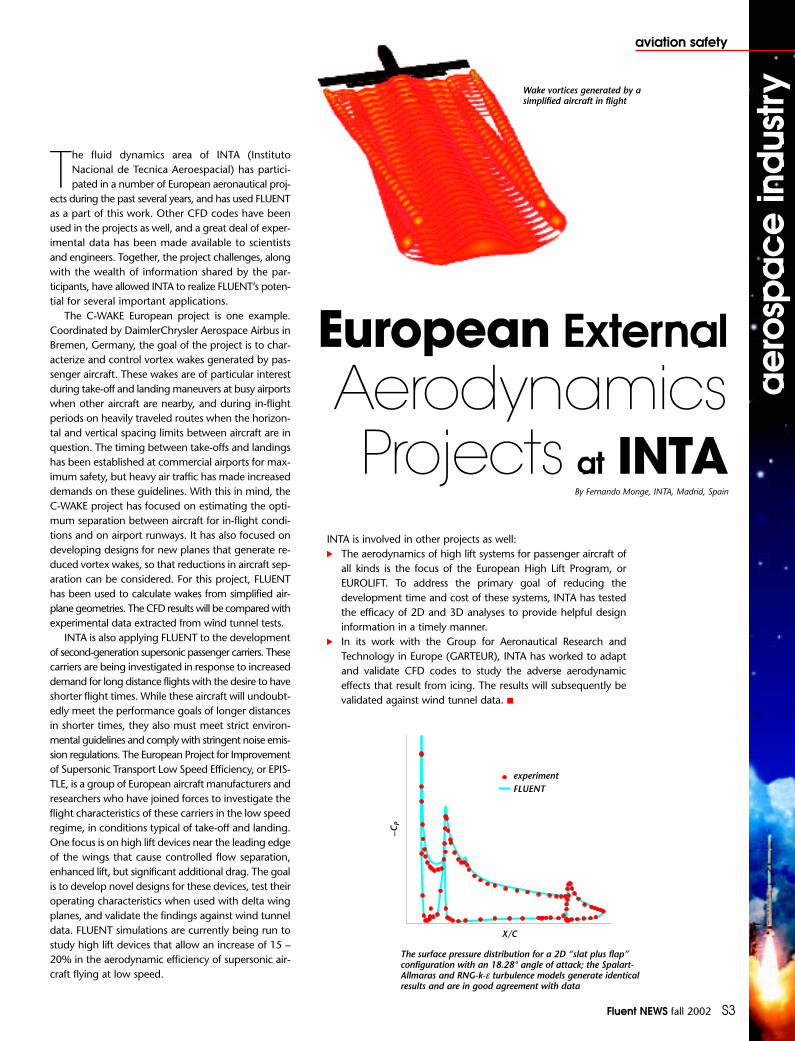
Wake vortices generated by asimplified aircraft in flight
INTA is involved in other projects as well:• The aerodynamics of high lift systems for passenger aircraft of
all kinds is the focus of the European High Lift Program, orEUROLIFT. To address the primary goal of reducing thedevelopment time and cost of these systems, INTA has testedthe efficacy of 2D and 3D analyses to provide helpful designinformation in a timely manner.
• In its work with the Group for Aeronautical Research andTechnology in Europe (GARTEUR), INTA has worked to adaptand validate CFD codes to study the adverse aerodynamiceffects that result from icing. The results will subsequently bevalidated against wind tunnel data. ■
The surface pressure distribution for a 2D “slat plus flap”configuration with an 18.28° angle of attack; the Spalart-Allmaras and RNG-k-ε turbulence models generate identicalresults and are in good agreement with data

It is, by now, standard practice at Boeingto design aerodynamic surfaces such asthe wings, engine nacelles (enclo-
sures), and fuselage using CFD instead ofrelying on expensive wind tunnel and flighttests. It is less common, and often moredifficult, to use CFD to analyze the moregeometrically complex parts of the airplane,such as high lift systems (flaps and slats),engine compartments, and auxiliarypower units. To perform such an analy-sis, engineers need to compute airflowsaround and through systems that are dis-tinguished by very complex geometry andflow patterns. A prime example involvespredicting the behavior of the efflux fromengine thrust reversers.
A typical commercial airplane deploysits thrust reversers briefly after touch down.A piece of engine cowling moves rearwardand blocker doors drop down, directingthe engine airflow into a honeycomb struc-ture called a cascade. The cascade directsthe flow forward, which acts to slow theaircraft and decrease lift for more effec-tive braking. The reverser is used preciselyat the time when high lift devices (i.e., wingleading and trailing edge flaps and slats)are fully deployed. Consequently, the plumesof hot exhaust must be directed so as tonot impinge on these devices. Other effectsto avoid are reingestion, in which thereversed plume reenters the engine inlet,engine ingestion of debris blown up fromthe runway, and plume envelopment ofthe vertical tail, which affects directionalcontrol. To avoid these effects, knowledgeof exactly where the exhaust plumes gois needed early in the design cyclebecause it affects such basic decisions asthe placement of the engine on the wing.
The CFD process begins with aCAD/CAM (Computer Aided Design/Computer Aided Manufacturing) modelof the aircraft. In addition to the engine,fuselage, and wing, the CAD/CAM modelincludes such devices as flaps, slats, andspoilers. An unstructured mesh is then builtaround the CAD/CAM model. For com-patibility with other CFD processes at Boeing,a commercial software package from ICEMCFD Engineering is used for mesh gen-eration. Starting from a new airplane CADgeometry, such a mesh, which typicallycontains from 3 to 8 million cells, can becreated in a day or two. Because the gridgeneration software contains a replay capa-bility, minor changes to the geometry canbe remeshed quickly. The mesh is parti-tioned into sections for parallel comput-ing, and the analysis is completed using
FLUENT’s flow solver. Depending on thenumber of CPUs available, a final solutioncan be obtained within a few hours afterthe geometry definition and mesh gen-eration are complete.
Because the entire CFD analysis cyclecan be completed in about three days,designers can use this tool repeatedly asa way to optimize the design. Wind tun-nel testing and expense are reduced, butthe key benefits are time and risk mitigation.If a need to change the design shouldbecome apparent after the tooling is builtand the aircraft is in the test phase, thedelay in entry into service and theexpense of retooling would be unac-ceptable. CFD modeling increases earlyconfidence in the design and shortens thedevelopment cycle to deliver a quality prod-uct on schedule. ■
S4 Fluent NEWS fall 2002
aviation safetya
eros
pa
ce in
dus
trya
eros
pa
ce in
dus
try Enhancing
ThrustReverserPerformance
By Dr. Chen Chuck, Research Engineer, and Dr. Douglas R. McCarthy, Research Engineer, The Boeing Company, Seattle, WA
Efflux pattern on the airplane for a Mach 0.15 case
The surface grid on the airplane, runway, symmetry plane, and downstream boundary

Fluent NEWS fall 2002 S5
electronics
aer
osp
ace
ind
ustry
aer
osp
ace
ind
ustryThermal control is important for the safe and reli-
able operation of electronic equipment. However,with increased functionality and the continued minia-
turization of electronic systems, increases in the amountof heat generated per unit volume have become an issue.Removing the internally generated heat requires an effec-tive path along which the heat can flow from the com-ponents to their surroundings. Cooling techniques suchas conduction, natural or forced convection, radiation,and liquid cooling are typically used, depending on thesituation. At Hamilton Sundstrand, FLUENT and Icepakhave both been used to simulate virtual prototypes ofelectronic equipment and the cooling mechanisms thatcould potentially be used to transfer heat. CFD has madeit possible to evaluate a number of possible designs beforebuilding an actual prototype for testing.
Using FLUENT, the thermal performance of one ofthe electronic control boxes of an aircraft was recentlyanalyzed. The controller houses the Motor DriveModule (MDM) of the flap/slat control unit, which isused to extend the flaps of a commercial aircraft dur-ing takeoff and landing, and to retract them when theyare no longer needed. The module fits inside the wingof the aircraft, and includes a powerful motor, with con-trol circuitry that dissipates a large amount of heat. Themodule geometry was created using Pro/ENGINEER® andimported into GAMBIT for mesh generation. The boxis cooled by fan-driven forced air, so the characteristicfan curve (for pressure vs. flow rate) was used as aninput for the CFD analysis. The simulation results showedvelocity and temperature distributions throughout the module, and helped engineers select the appropriateelectronic components for the unit. Detailed visuali-zation of the results helped to understand the systembehavior and improve it.
Icepak has also been used for many electronics cool-ing projects at Hamilton Sundstrand. For example, theair-cooling system of a control unit for an electro-hydraulicdrive unit (EHDU) inverter was recently studied. This unitconsists of a 65 kW variable speed permanent magnetelectric motor integrated with a 35 gallon/minute hydraulicpump. Using Icepak, engineers were able to easily posi-tion and reposition a number of internal componentsand fans in order to improve the circulation of the cool-ing air. The improved circulation allowed them to switchto a heat sink one-third as large as the one in the orig-inal design. When it became necessary to replace sev-eral components on a printed circuit board of the EHDU,Icepak was again used to determine the impact of thechange on the thermal conditions inside the enclosure.The analysis showed that the additional heat generat-ed by the new components raised temperaturesbeyond acceptable levels. Several alternative designs wereevaluated using CFD, and an effective cooling mecha-nism was identified and applied to the actual board.
Experimental data collected from these and other sys-tems have shown good agreement with the simulationresults, thus demonstrating the usefulness of CFD foranalyzing complicated systems. This kind of analysis hashelped improve product performance and safety, andhas saved a significant amount of time and money forthe company. ■
Temperature distribution inside the motor drive module
Temperature distribution on the heat sink of the EHDU
FLUENTand IcepakTeam Up forElectronicsCooling Analysis
By Dr. Samir El-Khabiry, Hamilton Sundstrand, Rockford, IL
S6 Fluent NEWS fall 2002
wind tunnelsa
eros
pa
ce in
dus
trya
eros
pa
ce in
dus
try
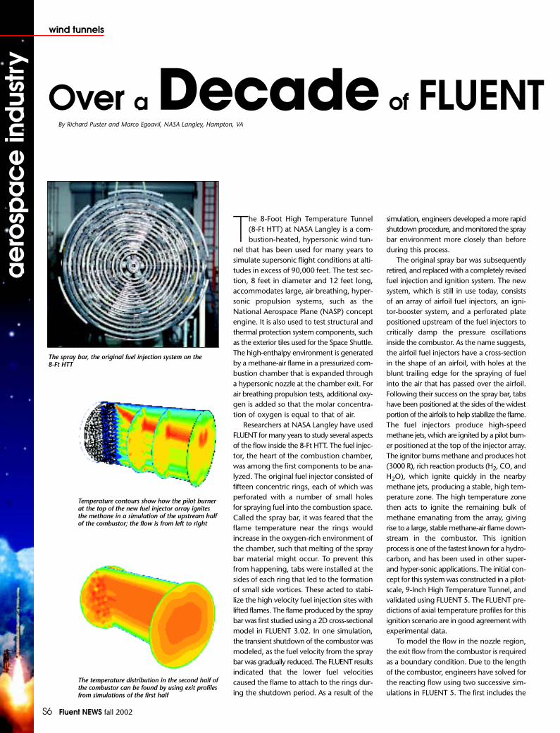
Temperature contours show how the pilot burnerat the top of the new fuel injector array ignitesthe methane in a simulation of the upstream halfof the combustor; the flow is from left to right
The temperature distribution in the second half ofthe combustor can be found by using exit profilesfrom simulations of the first half
The 8-Foot High Temperature Tunnel (8-Ft HTT) at NASA Langley is a com-bustion-heated, hypersonic wind tun-
nel that has been used for many years tosimulate supersonic flight conditions at alti-tudes in excess of 90,000 feet. The test sec-tion, 8 feet in diameter and 12 feet long,accommodates large, air breathing, hyper-sonic propulsion systems, such as theNational Aerospace Plane (NASP) conceptengine. It is also used to test structural andthermal protection system components, suchas the exterior tiles used for the Space Shuttle.The high-enthalpy environment is generatedby a methane-air flame in a pressurized com-bustion chamber that is expanded througha hypersonic nozzle at the chamber exit. Forair breathing propulsion tests, additional oxy-gen is added so that the molar concentra-tion of oxygen is equal to that of air.
Researchers at NASA Langley have usedFLUENT for many years to study several aspectsof the flow inside the 8-Ft HTT. The fuel injec-tor, the heart of the combustion chamber,was among the first components to be ana-lyzed. The original fuel injector consisted offifteen concentric rings, each of which wasperforated with a number of small holes for spraying fuel into the combustion space.Called the spray bar, it was feared that theflame temperature near the rings wouldincrease in the oxygen-rich environment ofthe chamber, such that melting of the spraybar material might occur. To prevent thisfrom happening, tabs were installed at thesides of each ring that led to the formationof small side vortices. These acted to stabi-lize the high velocity fuel injection sites withlifted flames. The flame produced by the spraybar was first studied using a 2D cross-sectionalmodel in FLUENT 3.02. In one simulation,the transient shutdown of the combustor wasmodeled, as the fuel velocity from the spraybar was gradually reduced. The FLUENT resultsindicated that the lower fuel velocitiescaused the flame to attach to the rings dur-ing the shutdown period. As a result of the
simulation, engineers developed a more rapidshutdown procedure, and monitored the spraybar environment more closely than beforeduring this process.
The original spray bar was subsequentlyretired, and replaced with a completely revisedfuel injection and ignition system. The newsystem, which is still in use today, consistsof an array of airfoil fuel injectors, an igni-tor-booster system, and a perforated platepositioned upstream of the fuel injectors tocritically damp the pressure oscillationsinside the combustor. As the name suggests,the airfoil fuel injectors have a cross-sectionin the shape of an airfoil, with holes at theblunt trailing edge for the spraying of fuelinto the air that has passed over the airfoil.Following their success on the spray bar, tabshave been positioned at the sides of the widestportion of the airfoils to help stabilize the flame.The fuel injectors produce high-speedmethane jets, which are ignited by a pilot burn-er positioned at the top of the injector array.The ignitor burns methane and produces hot(3000 R), rich reaction products (H2, CO, andH2O), which ignite quickly in the nearbymethane jets, producing a stable, high tem-perature zone. The high temperature zonethen acts to ignite the remaining bulk ofmethane emanating from the array, givingrise to a large, stable methane-air flame down-stream in the combustor. This ignitionprocess is one of the fastest known for a hydro-carbon, and has been used in other super-and hyper-sonic applications. The initial con-cept for this system was constructed in a pilot-scale, 9-Inch High Temperature Tunnel, andvalidated using FLUENT 5. The FLUENT pre-dictions of axial temperature profiles for thisignition scenario are in good agreement withexperimental data.
To model the flow in the nozzle region,the exit flow from the combustor is requiredas a boundary condition. Due to the lengthof the combustor, engineers have solved forthe reacting flow using two successive sim-ulations in FLUENT 5. The first includes the
Over a Decade of FLUENTBy Richard Puster and Marco Egoavil, NASA Langley, Hampton, VA
The spray bar, the original fuel injection system on the 8-Ft HTT

Fluent NEWS fall 2002 S7
wind tunnels
aer
osp
ace
ind
ustry
aer
osp
ace
ind
ustry
Simulations at
NASA Langleyaction of the fuel injectors and ignitor, extend-ing to the halfway point in the combustor.The second simulation takes the exit profilesfor all variables from the first simulation anduses them as inlet boundary conditions forthe second. The exit flow from the secondhalf can then be used for simulations of thenozzle. The nozzle itself is air-cooled by tinyjets of transpiration air injected through smallholes in the wall. To simulate this coolingmethod, eight mass flow inlets were positionedalong the nozzle wall to correspond to theeight coolant circuits used in the actual HTT.The simulations verified suspicions thatexcessive injection flow rates (over-cooling)would lead to separation upstream of the noz-zle throat. Based on these results, it was deter-mined that the coolant flow rates needed tobe adjusted very carefully to adequately coolthe nozzle and yield the desired conditionsin the test region.
In yet another project, simulations of thecombustor were used to study the spacingof the inlets used to deliver oxygen to thechamber. The oxygen is transported to thecombustor area in the liquid state, in pipingthat runs behind an insulating liner that sur-rounds the flame. When gaseous oxygen isintroduced to the hot combustion gases atthe injector site, it is cold by comparison, andcan cause a significant buoyancy effect. This
drives the hottest gases to the top if the cham-ber and can lead to overheating on the uppercombustor wall. FLUENT 5 was used to testthe uniformity of the temperature distribu-tion as a function of the cold oxidant bypass,or spacing between the fuel injectors andliner. The results showed that by reducingthe spacing to the smallest value tested, bet-ter mixing could be achieved, leading to moreuniform temperature distributions through-out the combustion chamber.
Many other applications have beensimulated and validated over the years atNASA Langley using FLUENT, resulting in asubstantial body of work. Some have beenwith chemical vapor deposition; somewith basic combustion; some with Scramjets;some with nozzles; some with high tem-perature structures; and some with advancedaircraft and missiles. ■
Editor’s Note: Richard Puster and Marco Egoavilhave worked for a combined total of 55 yearsat NASA Langley. While many FLUENT simu-lations have been run at NASA Langley duringtheir tenure, the organization also provided thefunding for the development of FLUENT/UNS,the first segregated FLUENT solver to work onan unstructured grid, and a precursor to FLUENT 5. Puster and Egoavil are both plan-ning to retire at the end of this calendar year.
Temperature contours on axial slices in the interior of thecombustor show the strong effect of buoyancy when thecold oxidant bypass is large; the high temperatures candamage the upper wall of the vessel liner and beunacceptable for testing
When the oxidant bypass is small, mixing of the cold gaswith the hot combustion products is improved, leading tomore uniform temperature distributions throughout thecombustor
The new fuel injection system, showing the airfoil fuelinjectors (red), ignitor (on top of the injector housing),damping plate (grey), and liquid oxygen piping system(purple)
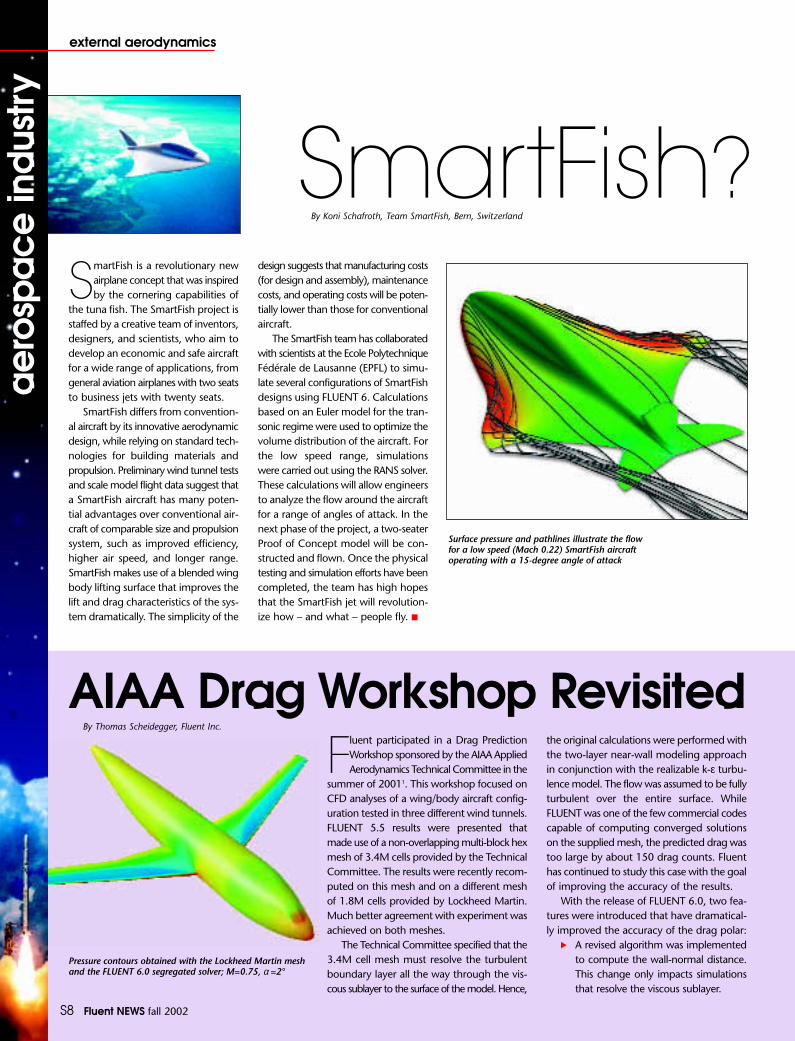
S8 Fluent NEWS fall 2002
external aerodynamicsa
eros
pa
ce in
dus
trya
eros
pa
ce in
dus
try
SmartFish is a revolutionary newairplane concept that was inspiredby the cornering capabilities of
the tuna fish. The SmartFish project isstaffed by a creative team of inventors,designers, and scientists, who aim todevelop an economic and safe aircraftfor a wide range of applications, fromgeneral aviation airplanes with two seatsto business jets with twenty seats.
SmartFish differs from convention-al aircraft by its innovative aerodynamicdesign, while relying on standard tech-nologies for building materials andpropulsion. Preliminary wind tunnel testsand scale model flight data suggest thata SmartFish aircraft has many poten-tial advantages over conventional air-craft of comparable size and propulsionsystem, such as improved efficiency, higher air speed, and longer range.SmartFish makes use of a blended wingbody lifting surface that improves thelift and drag characteristics of the sys-tem dramatically. The simplicity of the
design suggests that manufacturing costs(for design and assembly), maintenancecosts, and operating costs will be poten-tially lower than those for conventionalaircraft.
The SmartFish team has collaboratedwith scientists at the Ecole PolytechniqueFédérale de Lausanne (EPFL) to simu-late several configurations of SmartFishdesigns using FLUENT 6. Calculationsbased on an Euler model for the tran-sonic regime were used to optimize thevolume distribution of the aircraft. Forthe low speed range, simulationswere carried out using the RANS solver.These calculations will allow engineersto analyze the flow around the aircraftfor a range of angles of attack. In thenext phase of the project, a two-seaterProof of Concept model will be con-structed and flown. Once the physicaltesting and simulation efforts have beencompleted, the team has high hopesthat the SmartFish jet will revolution-ize how – and what – people fly. ■
SmartFish?By Koni Schafroth, Team SmartFish, Bern, Switzerland
Surface pressure and pathlines illustrate the flowfor a low speed (Mach 0.22) SmartFish aircraftoperating with a 15-degree angle of attack
Fluent participated in a Drag PredictionWorkshop sponsored by the AIAA AppliedAerodynamics Technical Committee in the
summer of 20011. This workshop focused onCFD analyses of a wing/body aircraft config-uration tested in three different wind tunnels.FLUENT 5.5 results were presented thatmade use of a non-overlapping multi-block hexmesh of 3.4M cells provided by the TechnicalCommittee. The results were recently recom-puted on this mesh and on a different meshof 1.8M cells provided by Lockheed Martin.Much better agreement with experiment wasachieved on both meshes.
The Technical Committee specified that the3.4M cell mesh must resolve the turbulentboundary layer all the way through the vis-cous sublayer to the surface of the model. Hence,
the original calculations were performed withthe two-layer near-wall modeling approachin conjunction with the realizable k-ε turbu-lence model. The flow was assumed to be fullyturbulent over the entire surface. While FLUENT was one of the few commercial codescapable of computing converged solutionson the supplied mesh, the predicted drag wastoo large by about 150 drag counts. Fluenthas continued to study this case with the goalof improving the accuracy of the results.
With the release of FLUENT 6.0, two fea-tures were introduced that have dramatical-ly improved the accuracy of the drag polar:
• A revised algorithm was implementedto compute the wall-normal distance.This change only impacts simulationsthat resolve the viscous sublayer.
AIAA Drag Workshop RevisitedBy Thomas Scheidegger, Fluent Inc.
Pressure contours obtained with the Lockheed Martin meshand the FLUENT 6.0 segregated solver; M=0.75, α =2°

Questions were recently raisedin the UK regarding the fir-ing of Hellfire anti-tank
missiles from Apache helicopters.Concerns were that debris ejected dur-ing the launch of a missile might causedamage to the main or tail rotor, result-ing in a possible crash. Engineers atFluent Europe performed an inde-pendent investigation into the poten-tial dangers through simulationsusing FLUENT.
A fully-loaded Apache helicopterin hovering flight mode was modeledusing over four million cells. Two Hellfireanti-tank missiles, one on either sideof the fuselage, were simulated dur-ing fire-up in their pre-launch posi-tions. The rotation of the main rotorwas represented using the sliding meshmodel and that of the tail rotor wasrepresented using the multiple referenceframes model. This approach allowedfor the complex interaction betweenthe main rotor downwash, the forced
convection from the helicopterengine exhausts, and the hot plumefrom two missiles being launched.
The results illustrated several inter-esting flow features. In par-ticular, the flows fromthe engine exhausts andmissile plumes were both found to besignificantly affected by the rotor down-wash, which redirects them towardthe left side of the helicopter. Whenthe left missile is fired, this flow pat-tern helps keep debris released withthe missile plumes from colliding withthe helicopter and rear rotor (whichis on the left side of the aircraft). Thediverted streams also cause asymmetricheating on the tail of the helicopter.When the right missile is fired, someinterference with the rear of the air-craft may occur for certain flight con-ditions, and more studies are neededto further study this possibility. The proj-ect as a whole illustrates how CFD canbe a viable source of information for
Fluent NEWS fall 2002 S9
external aerodynamics
aer
osp
ace
ind
ustry
aer
osp
ace
ind
ustry
Pathlines released from the missileexhausts (colored by release position)
• Second-order accurate recon-struction of the flow densitywas implemented in thesegregated solver. Prior to therelease of FLUENT 6.0, onlythe coupled solver had thiscapability.
With second-order accurate recon-struction of the density, the segregatedsolver now produces a drag polar vir-tually identical to that predicted bythe coupled solver on the 3.4M cellmesh. Furthermore, with the revisionto the wall-normal distance calcula-tion, the drag polar predicted by thetwo solvers on the 3.4M cell mesh ismuch closer to experimental values.At Mach = 0.75 and lift coefficient CL = 0.7, the drag coefficient CD isnow within 20 counts of the mean
experimental value, and within thestatistical dispersion (21 counts) of thecomputational results submitted to theTechnical Committee, as analyzed byMichael Hemsch1. Even better resultshave been obtained using a slightlymodified version of the 1.8M cell wall-function mesh supplied to theTechnical Committee by LockheedMartin after the workshop. Theimportance of the grid is made evi-dent in these calculations, as theimprovements to the accuracy of thedrag computed by the coupledsolver can be attributed solely to theuse of the Lockheed Martin mesh. ■
reference:1 http://aaac.larc.nasa.gov/tsab/cfdlarc/
aiaa-dpw/Workshop1/workshop1.html
Hellfire and Back
By Ben Simpson, Fluent Europe
investigations into safety issues for a wide range of flight conditions.For example, debris ejected when the missiles are launched could betracked using the discrete particle model in FLUENT. The likelihoodof the debris hitting the tail rotor or the main rotor could then beassessed using a series of runs to investigate the trajectories and pos-sible impact points of particles of various sizes and weights. ■
Drag polar obtained with the Lockheed Martinmesh; M=0.75, α =2°

S10 Fluent NEWS fall 2002
defensea
eros
pa
ce in
dus
trya
eros
pa
ce in
dus
try Tank and Artillery Cannon
Muzzle Brakes –Reducing Gun Recoil
QUIETLYBy Daniel L. Cler, Benet Laboratories, US Army, Watervliet, NY; and Christoph Hiemcke, Fluent Inc.
Benet Laboratories is a US Armyresearch laboratory involvedin the development of can-
non and mortar tubes for tanks andartillery. Cannon recoil impartsvery high loads on tanks and artilleryvehicles. These large loads are typ-ically managed by the mass of thevehicle in conjunction with a recoilsystem. The current trend in thedevelopment of new tank and artilleryvehicles is toward much lower vehi-cle weight, while at the same timethe muzzle velocities of projectilesare increasing. These changescombine to make it far more diffi-cult to manage the recoil loads.
One mechanism for reducingrecoil is the muzzle brake. Muzzlebrakes are used to turn some ofthe propellant flow behind an exit-ing projectile sideways or aft toreduce recoil. There are deleteri-ous effects associated with muz-zle brakes, however, such as veryhigh peak pressures and powerfulacoustic waves. The resultingnoise can potentially harm personneloperating the vehicle. For nearlytwenty years, Benet Laboratorieshas fostered the use of CFD to sim-ulate the unsteady wave propa-gation from cannon muzzle brakesin order to predict peak over-pres-sure of new muzzle brake designs.
By using a design tool such asCFD, the Army hopes to developefficient muzzle brakes that reducerecoil imparted to the vehiclewhile at the same time keeping thehigh noise levels manageable. In thepast, the only way to measure peakover-pressure was to test cannonhardware and record the value usingdynamic pressure instrumentation.Typically, scaled prototype cannons(20mm) can be fired for preliminaryresults early in the development pro-grams, but because of the high costinvolved, full scale testing is donelater on. Experimental results fromscaled cannons often jeopardize theprogram, as non-ideal behavior suchas ground plane reflections, inter-action with the vehicle hull, and dif-ferences between scale and full-sizedammunition alter the scale testingresults. It is hoped that by using CFDearly in the design cycle, much ofthe risk involved in muzzle brakedesign can be averted.
To accurately and efficiently pre-dict the performance and peak over-pressure of gun muzzles andmuzzle brakes, special CFD tech-niques for modeling unsteadywave propagation are required. Byusing the adaption tools in FLUENT,one is able to create and destroygrid along propagating shock
Adapted grid at 350 microseconds before the shot exit
Experimental results showing the flow field at350 microseconds before the shot exit2 illustratedusing a shadowgraph imaging technique, wherethe second derivative of density is used to markwavefronts and shocks
Contours of density gradient from FLUENT resultsat 350 microseconds before the shot exit;displaying the density gradient corresponds tothe Schlieren imaging technique used to identifywavefronts and shocks experimentallyvisualization by EnSight from CEI
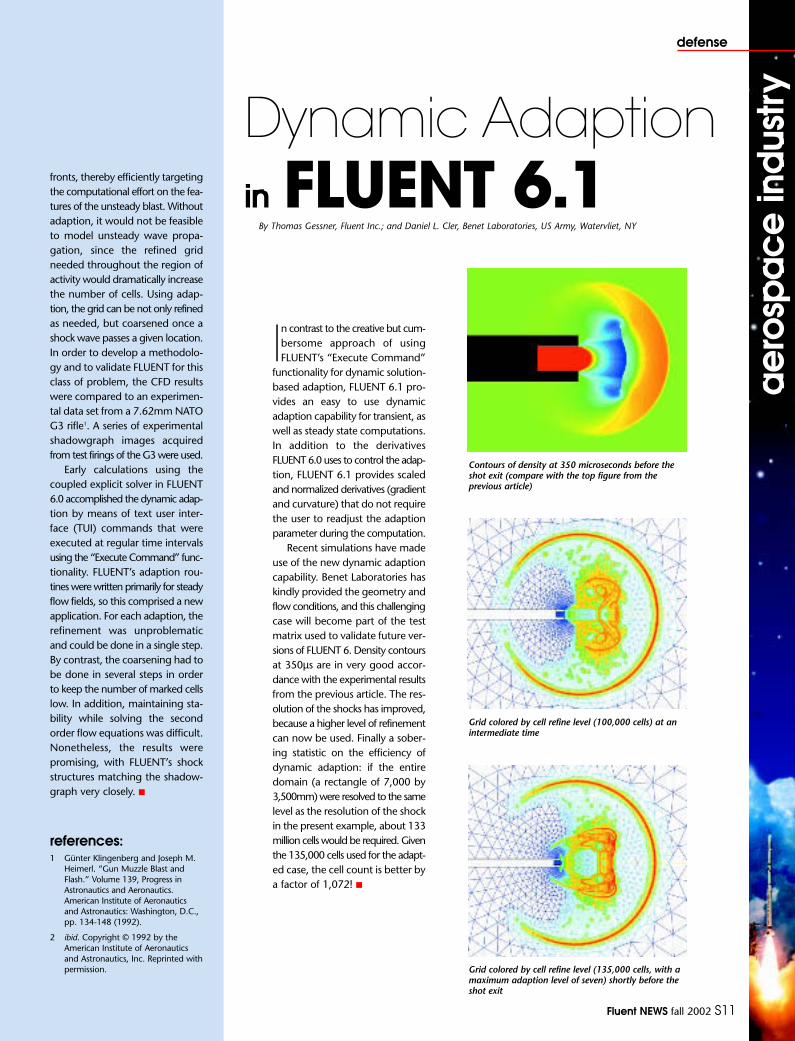
Fluent NEWS fall 2002 S11
defense
aer
osp
ace
ind
ustry
aer
osp
ace
ind
ustry
fronts, thereby efficiently targetingthe computational effort on the fea-tures of the unsteady blast. Withoutadaption, it would not be feasibleto model unsteady wave propa-gation, since the refined gridneeded throughout the region ofactivity would dramatically increasethe number of cells. Using adap-tion, the grid can be not only refinedas needed, but coarsened once ashock wave passes a given location.In order to develop a methodolo-gy and to validate FLUENT for thisclass of problem, the CFD resultswere compared to an experimen-tal data set from a 7.62mm NATOG3 rifle1. A series of experimentalshadowgraph images acquiredfrom test firings of the G3 were used.
Early calculations using thecoupled explicit solver in FLUENT6.0 accomplished the dynamic adap-tion by means of text user inter-face (TUI) commands that wereexecuted at regular time intervalsusing the “Execute Command” func-tionality. FLUENT’s adaption rou-tines were written primarily for steadyflow fields, so this comprised a newapplication. For each adaption, therefinement was unproblematicand could be done in a single step.By contrast, the coarsening had tobe done in several steps in orderto keep the number of marked cellslow. In addition, maintaining sta-bility while solving the second order flow equations was difficult.Nonetheless, the results werepromising, with FLUENT’s shockstructures matching the shadow-graph very closely. ■
references:1 Günter Klingenberg and Joseph M.
Heimerl. “Gun Muzzle Blast andFlash.” Volume 139, Progress inAstronautics and Aeronautics.American Institute of Aeronauticsand Astronautics: Washington, D.C.,pp. 134-148 (1992).
2 ibid. Copyright © 1992 by theAmerican Institute of Aeronauticsand Astronautics, Inc. Reprinted withpermission.
In contrast to the creative but cum-bersome approach of usingFLUENT’s “Execute Command”
functionality for dynamic solution-based adaption, FLUENT 6.1 pro-vides an easy to use dynamicadaption capability for transient, aswell as steady state computations.In addition to the derivatives FLUENT 6.0 uses to control the adap-tion, FLUENT 6.1 provides scaledand normalized derivatives (gradientand curvature) that do not requirethe user to readjust the adaptionparameter during the computation.
Recent simulations have madeuse of the new dynamic adaptioncapability. Benet Laboratories haskindly provided the geometry andflow conditions, and this challengingcase will become part of the testmatrix used to validate future ver-sions of FLUENT 6. Density contoursat 350µs are in very good accor-dance with the experimental resultsfrom the previous article. The res-olution of the shocks has improved,because a higher level of refinementcan now be used. Finally a sober-ing statistic on the efficiency ofdynamic adaption: if the entiredomain (a rectangle of 7,000 by3,500mm) were resolved to the samelevel as the resolution of the shockin the present example, about 133million cells would be required. Giventhe 135,000 cells used for the adapt-ed case, the cell count is better bya factor of 1,072! ■
Contours of density at 350 microseconds before theshot exit (compare with the top figure from theprevious article)
Grid colored by cell refine level (100,000 cells) at anintermediate time
Grid colored by cell refine level (135,000 cells, with amaximum adaption level of seven) shortly before theshot exit
Dynamic Adaptionin FLUENT 6.1
By Thomas Gessner, Fluent Inc.; and Daniel L. Cler, Benet Laboratories, US Army, Watervliet, NY

S12 Fluent NEWS fall 2002
fuel injectorsa
eros
pa
ce in
dus
trya
eros
pa
ce in
dus
try High PerformanceFuel Injector Design
By Philip Buelow and Steven Smith, Turbine Fuel Technologies, Goodrich Corporation, West Des Moines, IA
Effective design of high-performance fuelinjectors for aircraft and power-gen-eration gas turbine engines requires
a clear understanding of both the aerody-namic and hydraulic flow fields of the injec-tor. At Goodrich Corporation’s Turbine FuelTechnologies, FLUENT has been used exten-sively for this purpose.
Injector life and engine performance canbe severely limited by the formation of car-bonaceous deposits within the fuel circuits and/or on the face of the injector. These depositscan take the form of varnishes, gums, or softor hard carbon, and always form from the fuel.On internal liquid fuel passageways, they tendto form if the “wetted wall” temperatures exceedcertain values. Carbon deposits on the faceof the injector are typically due to inadequateaerodynamic wiping of the face by compressordischarge air.
CFD simulations using FLUENT havebecome the mainstay at Turbine FuelTechnologies for predicting the likelihoodthat a nozzle will form carbon deposits.Predictions of heat transfer coefficienthave been used effectively to estimate thewetted wall temperatures within the liquidfuel circuits in order to design injectors with
a reduced propensity to form deposits. Timeand again, FLUENT has proved to be an invalu-able tool for predicting the presence of flowfield features that are historically related to carbon formation, and for guiding designchanges to prevent it from happening.
One of the primary functions of a fuel injec-tor is to atomize the fuel into very small dropletsso that it can adequately mix with air for thecombustion process. Recently, Turbine FuelTechnologies has used FLUENT’s VOF modelto simulate the formation of the thin liquidfuel film1, which is a precursor to atomization.
In the simplex atomizer, the fuel entersthe spin chamber through angled spin-slots,which impart a strong swirling motion to theflow. As the flow exits the atomizer throughthe orifice, it spreads out into a conical sheet.A key characteristic of such flows is the for-mation of an air core along the centerlineof the atomizer. This air-core typicallyextends all the way to the back end of thespin chamber, and is correctly captured bythe FLUENT simulation. Other key charac-teristics are the film thickness, film velocities,and the angle of the conical sheet exitingthe atomizer. These parameters can be takenfrom the FLUENT simulation and input into
Comparison of cone angle between experiment(128°) and CFD (121°) for a pure air-blastatomizer operating at a mass flowrate of0.0139 kg/sec (110 lbm/hr)
Turbine Fuel Technologies’ proprietary soft-ware to estimate film break-up lengths anddroplet Sauter Mean Diameters (SMDs).
In contrast to simplex atomizers, whichutilize high-pressure in the fuel circuit to drivethe atomization process, pure-airblast atom-izers use relatively low-pressure fuel along withhigh velocity air adjacent to the fuel film to drive the atomization process. A recent FLUENT simulation modeled a pure-airblastatomizer under liquid-only operation (i.e. nodriving air-pressure) so that a distinct coni-cal fuel film could be observed. The CFD resultswere compared with an experimentallydetermined cone angle, and yielded reason-able agreement, with the cone angle under-predicted by only 5.5%. Further results on thepure-airblast simulations can be found inReference 1. ■
Reference1 Buelow, P.E.O., Mao, C-P., Smith, S., Bretz, D.,
“Application of Two-Phase CFD Analysis to aPrefilming Pure-Airblast Atomizer,” AIAA Paper2001-3938, July 2001.
120-degree cut-out of a pure-airblastatomizer showing the liquid fuel (red)and the air (blue); flow is from left toright
120-degree cut-out of a simplexatomizer showing the liquid fuel(red) and the air (blue); flow isfrom left to right

equipment manufacturers
Fluent NEWS fall 2002 23
The Compact Brazed HeatExchanger (CBE) is one of the mostefficient ways to transfer heat from
one medium to another. CBEs can beused in many different applications forboth heating and cooling. They are rou-tinely used in supermarket refrigera-tion units, air-conditioners, anddomestic tap water heaters. A CBE con-sists of many corrugated plates com-bined to create complex channelsthrough which a hot fluid and a coldone can be distributed. Without evermixing, the fluids come into close prox-imity inside the CBE, and heat is trans-ferred from one to the other as theyflow side-by-side.
CFD is a powerful tool for improv-ing the heat transfer efficiency of a CBEbecause it allows the flow in the CBEchannels to be simulated in threedimensions. The design of the CBE mustoffer both mechanical strength andhigh thermal performance, so it isimportant to be able to simulate newpatterns and geometries quickly andefficiently. CFD readily allows this tobe done. Predictions can be validat-ed experimentally, giving engineersa high level of confidence in them.
SWEP is the world’s leading man-ufacturer of CBEs, and has beenusing CFD since 1997. FLUENT was cho-sen because of its ability to importgeometries from 3D CAD packages.The automatic tetrahedral meshing feature was also important. At that time,only a small region of the heatexchanger could be simulated - theregion between four braze points, cor-
responding to an area of about50mm2 – and periodic boundaryconditions were frequently used. Withimprovements in the software and speedincreases in affordable computer sys-tems, it became possible to simulateentire channels. During the past fiveyears, the size and complexity of ourmodels have increased, yet the timespent on meshing and solving themhas been drastically reduced.
Simulations using FLUENT have beenvery important in the development ofnew, improved CBEs that offer betterheat transfer and shorter time-to-mar-ket. The ongoing effort with CFD hasalso had an organizational impact. Acloser cooperation has evolved betweenthe Design and the Heat TransferResearch departments, who share thecommon goal of making better useof the simulation possibilities. The designdepartment uses Mechanical Desktop5.0, which generates ACIS-basedgeometries that are easily meshed byGAMBIT. The heat transfer researchdepartment uses FLUENT 6.0 to gen-erate a solution that gives informationabout the flow, which is then used toimprove the design. The design engi-neers make modifications and theprocess repeats itself. There are still lim-itations in the development process,however. For example, it is still not prac-tical to simulate the entire CBE,which consists of many parallel chan-nels, ports and connections. Yet withthe speed of computers continuing torise, even this prospect will soon becomepossible. ■
High Performance
CompactHeat Exchangers
By Olivier Pelletier, Manager of Heat Transfer Research, and Fredrik Strömer, CFD Engineer, SWEP International AB, Sweden
CBE channel with tetrahedral cells
Pathlines in the CBE channel colored by velocity
Compact brazed heat exchangers

24 Fluent NEWS fall 2002
power generation
Throughout the power generation industry, controlling theemission of nitrogen oxides (NOx) has been of interestfor many years. During this time, equipment such as low-
NOx burners, and combustion modification methods like reburn-ing, air staging, and flue-gas recirculation have beendeveloped. Reburning is a process in which fuel not burnedin the primary combustion zone is diverted to a secondary com-bustion zone downstream of the first, where it is reburned usingadditional fuel. The hydrocarbons in the reburn zone react withand eliminate some of the NOx created in the primary com-bustion zone. Air staging, also called overfire air technology,is a process that divides the combustion air into primary andsecondary streams. NOx generated by the fuel-rich conditionsof the fuel and primary air mixture are reduced in the com-bustion zone that incorporates the secondary air. Flue gas recir-culation involves the injection of some of the flue gas into thecombustion zone for further burning. This process results inreduced flame temperatures, and subsequent reductions in NOxproduction. To meet current emissions standards, several ofthese methods have been coupled recently with the use of non-conventional fuels, such as coal-water slurries and biomass, inhopes of finding NOx reduction solutions that can be appliedto a large variety of boilers.
Researchers at Penn State University have been using FLUENT to optimize the design of a pilot-scale combustor thatuses a number of NOx control methods, including a low-NOxburner, air staging, and reburning. The facility is a 147 kW down-fired combustor for which extensive experimental data has beencollected. CFD simulations of the unit have made use of FLUENT’sNOx module with the reburn option to evaluate the performanceof several optimized designs. A baseline mode of operation wasestablished with 0% reburn fuel and pulverized coal as the pri-mary fuel. The mesh and boundary conditions in the numer-ical model were adjusted to best match the experiments carriedout for this mode. Once these tests were completed, the mod-eling of optimized scenarios, including different fuels and fir-ing configurations, was initiated.
Several combustor designs and operating conditions wereconsidered. The effects of mixing, residence time, air staging,and reburning were studied. The performance of natural gas,coal, coal-water slurry, and biomass as reburn fuels was pre-dicted using numerical simulations and compared with meas-urements. Reduction of NOx levels was targeted at every stage,with the results being coupled with optimized parameters formixing and injection configurations. A sensitivity analysis wasconducted to estimate the variations of the predictions withrespect to the model parameters.
The CFD results showed that improved mixing and burn-er aerodynamics contribute significantly to lowering the pri-mary-zone NOx levels. This fact, coupled with optimized injectionconfigurations and reburning parameters, resulted in impor-tant reductions in NOx emissions. In a comparison of fuels,tests indicated a NOx reduction of up to 74% over the base-line case for natural gas reburning and 48% for coal-water slur-ry reburning. These both represent a major improvement overthe maximum reduction obtained previously on the same unitfor non-optimized configurations. In short, the CFD-optimizedcombustor design resulted in significant reduction of NOx emis-sions, and at the same time provided insight into the NOx con-trol mechanism and the complex interaction between keycombustor operating parameters. ■
Who ya gonna call?
NOBUSTERS
By Vlad Zarnescu, Columbian Chemicals Company, Marietta, GA; and Sarma V. Pisupati, Energy and Geo-Environmental EngineeringDepartment, Pennsylvania State University, University Park, PA
Mixing optimization by varying the injection site for the reburn fuel
–port 1–port 2
–port 3
–port 4
–port 5
Surface grid for the down-fired combustor
Comparison between experimental values (red circles) and FLUENTpredictions (blue lines) for axial temperature (top) and NOx(bottom) profiles for the baseline case
x
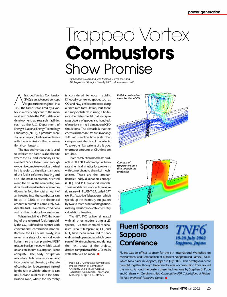
Fluent Sponsors Sapporo ConferenceFluent was an official sponsor for the 6th International Workshop onMeasurement and Computation of Turbulent Nonpremixed Flames (TNF6),which took place in Sapporo, Japan in July 2002. This prestigious eventbrought together thought leaders in the area of combustion from aroundthe world. Among the posters presented was one by Stephen B. Popeand Graham M. Goldin entitled Composition PDF Calculations of Piloted-Jet Non-Premixed Turbulent Flames. ■
Fluent NEWS fall 2002 25
power generation
ATrapped Vortex Combustor(TVC) is an advanced conceptfor gas turbine engines. In a
TVC, the flame is stabilized by a vor-tex in a cavity adjacent to the mainair stream. While the TVC is still underdevelopment at research facilities such as the U.S. Department ofEnergy’s National Energy TechnologyLaboratory (NETL), it promises morestable, compact, fuel-flexible flameswith lower emissions than conven-tional combustors.
The trapped vortex that is usedto stabilize the flame is also the sitewhere the fuel and secondary air areinjected. Since there is not enoughoxygen to completely oxidize the fuelin this region, a significant amountof the fuel is reformed into H2 andCO. The main air-stream, orientedalong the axis of the combustor, oxi-dizes the reformed fuel under lean con-ditions. In fact, the total amount ofair injected into the combustor canbe up to 250% of the theoreticalamount required to completely oxi-dize the fuel. Lean flame conditionssuch as this produce low emissions.
When simulating a TVC, the burn-ing of the reformed fuels, especial-ly the CO, is difficult to capture withconventional combustion models.Because the CO burns slowly, it isnever in a state of chemical equi-librium, so the non-premixed PDF/mixture fraction model, which is basedon an equilibrium assumption, is notadequate. The eddy dissipationmodel also fails because it does notincorporate real chemistry – the rateof combustion is determined insteadby the rate at which turbulence canmix fuel and oxidizer into the com-bustion zone, where the chemistry
is considered to occur rapidly.Kinetically controlled species such asCO and NOx are best modeled usinga finite rate formulation, but thereis a major obstacle in using a finite-rate chemistry model that incorpo-rates dozens of species and hundredsof reactions in multi-dimensional CFDsimulations. The obstacle is that thechemical mechanisms are invariablystiff, with reaction time scales thatcan span several orders of magnitude.To solve chemical systems of this type,enormous amounts of CPU time arerequired.
Three combustion models are avail-able in FLUENT that can capture finite-rate chemical kinetics for problemswith comprehensive chemical mech-anisms. These are the laminar-flamelet, eddy-dissipation concept(EDC), and PDF transport models.These models can work with an algo-rithm, new in FLUENT 6.1, called ISAT(In-Situ Adaptive Tabulation)1, whichspeeds up the chemistry integrationby two to three orders of magnitude,making realistic finite-rate chemistrycalculations feasible.
The NETL TVC has been simulatedwith all three models using a 23species, 104 step chemical mecha-nism. Exhaust temperature, CO, andNOx have been measured for nat-ural gas fuel operating at a high pres-sure of 10 atmospheres, and duringthe next phase of the project,detailed comparisons of the CFD resultswith data will be made. ■
1 Pope, S.B., “Computationally EfficientImplementation of CombustionChemistry Using In-Situ AdaptiveTabulation” Combustion Theory andModeling, 1, pp. 41-63, (1997).
Trapped VortexCombustorsShow Promise
By Graham Goldin and Jens Madsen, Fluent Inc.; andBill Rogers and Douglas Straub, NETL, Morgantown, WV
Pathlines colored bymass fraction of CO
Contours oftemperature on aslice through thecombustor
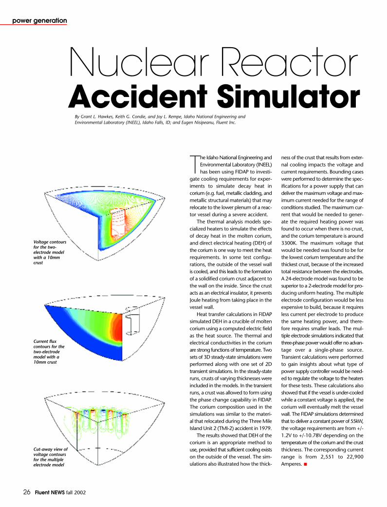
26 Fluent NEWS fall 2002
power generation
The Idaho National Engineering andEnvironmental Laboratory (INEEL)has been using FIDAP to investi-
gate cooling requirements for exper-iments to simulate decay heat in corium (e.g. fuel, metallic cladding, andmetallic structural materials) that mayrelocate to the lower plenum of a reac-tor vessel during a severe accident.
The thermal analysis models spe-cialized heaters to simulate the effectsof decay heat in the molten corium,and direct electrical heating (DEH) ofthe corium is one way to meet the heatrequirements. In some test configu-rations, the outside of the vessel wallis cooled, and this leads to the formationof a solidified corium crust adjacent tothe wall on the inside. Since the crustacts as an electrical insulator, it preventsJoule heating from taking place in thevessel wall.
Heat transfer calculations in FIDAPsimulated DEH in a crucible of moltencorium using a computed electric fieldas the heat source. The thermal andelectrical conductivities in the coriumare strong functions of temperature. Twosets of 3D steady-state simulations wereperformed along with one set of 2Dtransient simulations. In the steady-stateruns, crusts of varying thicknesses wereincluded in the models. In the transientruns, a crust was allowed to form usingthe phase change capability in FIDAP.The corium composition used in thesimulations was similar to the materi-al that relocated during the Three MileIsland Unit 2 (TMI-2) accident in 1979.
The results showed that DEH of thecorium is an appropriate method touse, provided that sufficient cooling existson the outside of the vessel. The sim-ulations also illustrated how the thick-
ness of the crust that results from exter-nal cooling impacts the voltage andcurrent requirements. Bounding caseswere performed to determine the spec-ifications for a power supply that candeliver the maximum voltage and max-imum current needed for the range ofconditions studied. The maximum cur-rent that would be needed to gener-ate the required heating power wasfound to occur when there is no crust,and the corium temperature is around3300K. The maximum voltage thatwould be needed was found to be forthe lowest corium temperature and thethickest crust, because of the increasedtotal resistance between the electrodes.A 24-electrode model was found to besuperior to a 2-electrode model for pro-ducing uniform heating. The multipleelectrode configuration would be lessexpensive to build, because it requiresless current per electrode to producethe same heating power, and there-fore requires smaller leads. The mul-tiple electrode simulations indicated thatthree-phase power would offer no advan-tage over a single-phase source.Transient calculations were performedto gain insights about what type ofpower supply controller would be need-ed to regulate the voltage to the heatersfor these tests. These calculations alsoshowed that if the vessel is under-cooledwhile a constant voltage is applied, thecorium will eventually melt the vesselwall. The FIDAP simulations determinedthat to deliver a constant power of 55kW,the voltage requirements are from +/-1.2V to +/-10.78V depending on thetemperature of the corium and the crustthickness. The corresponding currentrange is from 2,551 to 22,900Amperes. ■
Nuclear ReactorAccident Simulator
By Grant L. Hawkes, Keith G. Condie, and Joy L. Rempe, Idaho National Engineering and Environmental Laboratory (INEEL), Idaho Falls, ID; and Eugen Nisipeanu, Fluent Inc.
Voltage contoursfor the two-electrode modelwith a 10mmcrust
Current fluxcontours for thetwo-electrodemodel with a10mm crust
Cut-away view ofvoltage contoursfor the multipleelectrode model
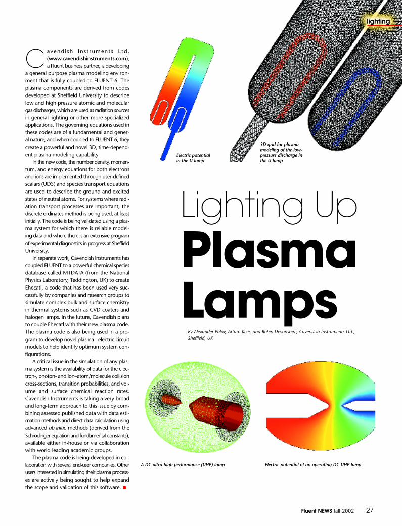
Fluent NEWS fall 2002 27
C avend i sh In s t rument s L td .(www.cavendishinstruments.com),a Fluent business partner, is developing
a general purpose plasma modeling environ-ment that is fully coupled to FLUENT 6. Theplasma components are derived from codesdeveloped at Sheffield University to describelow and high pressure atomic and moleculargas discharges, which are used as radiation sourcesin general lighting or other more specializedapplications. The governing equations used inthese codes are of a fundamental and gener-al nature, and when coupled to FLUENT 6, theycreate a powerful and novel 3D, time-depend-ent plasma modeling capability.
In the new code, the number density, momen-tum, and energy equations for both electronsand ions are implemented through user-definedscalars (UDS) and species transport equationsare used to describe the ground and excitedstates of neutral atoms. For systems where radi-ation transport processes are important, thediscrete ordinates method is being used, at leastinitially. The code is being validated using a plas-ma system for which there is reliable model-ing data and where there is an extensive programof experimental diagnostics in progress at SheffieldUniversity.
In separate work, Cavendish Instruments hascoupled FLUENT to a powerful chemical speciesdatabase called MTDATA (from the NationalPhysics Laboratory, Teddington, UK) to createEhecatl, a code that has been used very suc-cessfully by companies and research groups tosimulate complex bulk and surface chemistryin thermal systems such as CVD coaters andhalogen lamps. In the future, Cavendish plansto couple Ehecatl with their new plasma code.The plasma code is also being used in a pro-gram to develop novel plasma - electric circuitmodels to help identify optimum system con-figurations.
A critical issue in the simulation of any plas-ma system is the availability of data for the elec-tron-, photon- and ion–atom/molecule collisioncross-sections, transition probabilities, and vol-ume and surface chemical reaction rates.Cavendish Instruments is taking a very broadand long-term approach to this issue by com-bining assessed published data with data esti-mation methods and direct data calculation usingadvanced ab initio methods (derived from theSchrödinger equation and fundamental constants),available either in-house or via collaborationwith world leading academic groups.
The plasma code is being developed in col-laboration with several end-user companies. Otherusers interested in simulating their plasma process-es are actively being sought to help expandthe scope and validation of this software. ■
Lighting UpPlasma Lamps
By Alexander Palov, Arturo Keer, and Robin Devonshire, Cavendish Instruments Ltd.,Sheffield, UK
A DC ultra high performance (UHP) lamp Electric potential of an operating DC UHP lamp
Electric potentialin the U-lamp
3D grid for plasmamodeling of the low-pressure discharge inthe U-lamp
lighting

28 Fluent NEWS fall 2002
environmental
Engineers at Fluent Italy recently worked as external consultants in a court-room trial. At issue was the cause of a building fire in Milan, Italy thatclaimed three lives and injured several others. The fire set off an explo-
sion in the apartment where it originated, causing the collapse of some ofthe inner partition walls, floor slabs, and outer walls.
A poorly functioning distribution nozzle (burner) for the gas stove in thesmall kitchen, that was using a mixture of propane and butane fuel, was sus-pected to be the main cause of the event. The diffusion of fuel vapors intothe flat’s rooms may have caused, after a few hours of leakage, at certain loca-tions, the lower flammability limit (LFL) to be exceeded. In these locations, anecessary (but hypothetical) ignition source could have easily set off the explo-sion. The legal action, which involved the insurance company and the build-ing construction firm, is still pending. The work performed by Fluent was donewith the full support of the lawyers and technical experts from both sides.
Judgement Day for CFD Technology
By Emanuela Colombo, Ph.D., Energy Department, Politecnico di Milano, Italy; and Diego Donati and Marco Rossi, Fluent Italy
The building after the explosion shows thefull extent of the damage
The FLUENT model consisted of the entire apartment and twoseparate volumes of outside cold air adjacent to the wallscontaining windows. The small kitchen contained a simplifiedstove and wall vent, used for exhaust fumes.
A few iso-surfaces of fuel vapor, colored by temperature,throughout the apartment
Bedroom
LivingRoom
SmallKitchen
All the model details, including boundary conditions for the gas nozzle,properties of the gaseous vapors, and indoor and outdoor temperatures werereviewed with the lawyers from both sides prior to the start of the project.The unsteady simulation was run using a 3D model of the apartment, whichcovered roughly 90 m2. A small vent (100 cm2) in the kitchen, required byItalian law for exhausting flue gases, was modeled in both the open and closedposition, to test its efficacy.
Meshes of approximately 350,000 cells, most of which were hexahedral,were used for the simulations. The fuel vapors were assigned a concentrationof 40% propane and 60% butane. Transport equations were solved for thesecomponents as well as for oxygen and nitrogen. Flammability limits for thiscomposition were calculated according to Le Chatelier’s formulation, and foundto be in the range of 0.02 - 0.09. To ensure the development of the propernatural convection currents at the time, two service volumes were used out-side the apartment windows to simulate the external atmosphere of the win-ter day when the accident occurred.
The simulation results for the case of a closed kitchen vent and gas flowrate of 0.070 kg/hr indicated that the fuel and oxygen mixture was below theLFL everywhere except in the area close to the gas inlet. With the vent open,two counterproductive effects were observed. First, fresh air was drawn intothe room. Second, the cold outside air set up local circulation currents thatimpeded the diffusion of gas vapors throughout the remainder of the apart-ment. This caused a higher concentration of vapors to be found in the kitchenthan in the scenario with the vent closed. While each scenario predicted smallregions where the vapors were in excess of the LFL, neither was consideredto present the kind of conditions that would lead to an explosion of the mag-nitude that occurred.
It was concluded that the results were strongly dependent on the definedscenario given by the parties, according to which the simulation was based.The actual conditions, such as the indoor and outdoor temperatures and degreeof closure of the vent, may have been different enough to alter the drivingforces behind the air and gas flows. Indeed, small differences might have beenenough to give rise to a different explosion mixture which, given the oppor-tunity to ignite, could have generated the damage that occurred. ■
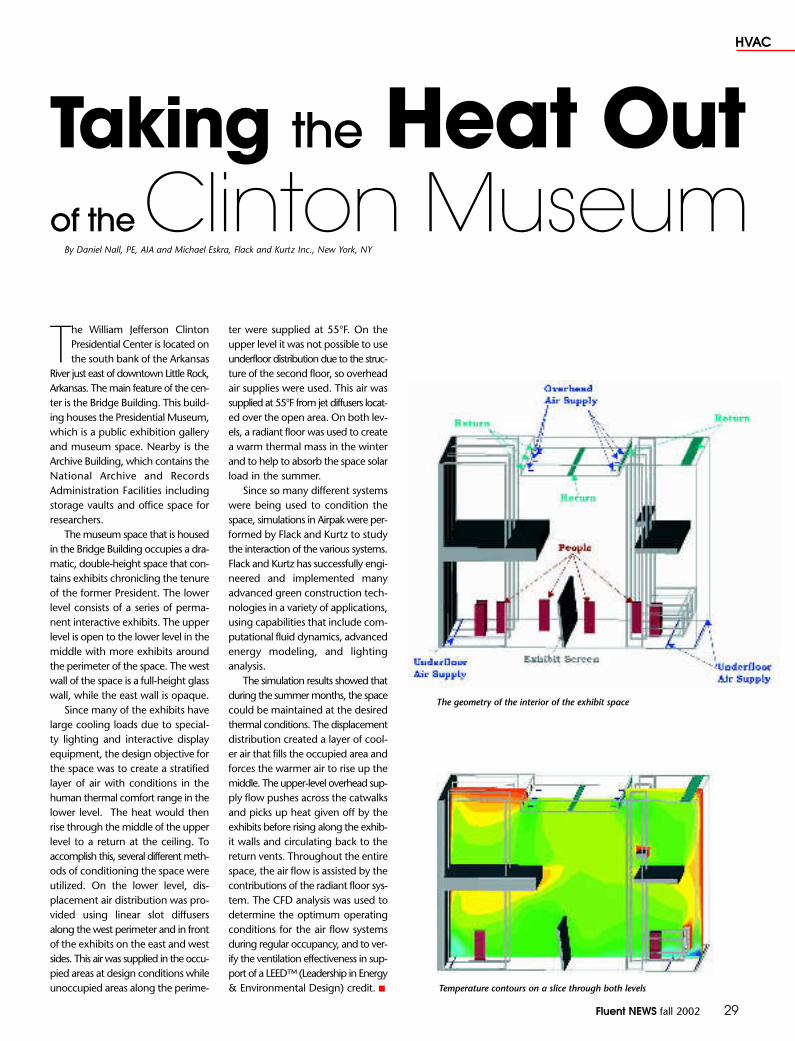
Fluent NEWS fall 2002 29
HVAC
Taking the Heat Outof the Clinton Museum
By Daniel Nall, PE, AIA and Michael Eskra, Flack and Kurtz Inc., New York, NY
The William Jefferson ClintonPresidential Center is located onthe south bank of the Arkansas
River just east of downtown Little Rock,Arkansas. The main feature of the cen-ter is the Bridge Building. This build-ing houses the Presidential Museum,which is a public exhibition galleryand museum space. Nearby is theArchive Building, which contains theNational Archive and RecordsAdministration Facilities includingstorage vaults and office space forresearchers.
The museum space that is housedin the Bridge Building occupies a dra-matic, double-height space that con-tains exhibits chronicling the tenureof the former President. The lowerlevel consists of a series of perma-nent interactive exhibits. The upperlevel is open to the lower level in themiddle with more exhibits aroundthe perimeter of the space. The westwall of the space is a full-height glasswall, while the east wall is opaque.
Since many of the exhibits havelarge cooling loads due to special-ty lighting and interactive displayequipment, the design objective forthe space was to create a stratifiedlayer of air with conditions in thehuman thermal comfort range in thelower level. The heat would thenrise through the middle of the upperlevel to a return at the ceiling. Toaccomplish this, several different meth-ods of conditioning the space wereutilized. On the lower level, dis-placement air distribution was pro-vided using linear slot diffusersalong the west perimeter and in frontof the exhibits on the east and westsides. This air was supplied in the occu-pied areas at design conditions whileunoccupied areas along the perime-
ter were supplied at 55°F. On theupper level it was not possible to useunderfloor distribution due to the struc-ture of the second floor, so overheadair supplies were used. This air wassupplied at 55°F from jet diffusers locat-ed over the open area. On both lev-els, a radiant floor was used to createa warm thermal mass in the winterand to help to absorb the space solarload in the summer.
Since so many different systemswere being used to condition thespace, simulations in Airpak were per-formed by Flack and Kurtz to studythe interaction of the various systems.Flack and Kurtz has successfully engi-neered and implemented manyadvanced green construction tech-nologies in a variety of applications,using capabilities that include com-putational fluid dynamics, advancedenergy modeling, and lightinganalysis.
The simulation results showed thatduring the summer months, the spacecould be maintained at the desiredthermal conditions. The displacementdistribution created a layer of cool-er air that fills the occupied area andforces the warmer air to rise up themiddle. The upper-level overhead sup-ply flow pushes across the catwalksand picks up heat given off by theexhibits before rising along the exhib-it walls and circulating back to thereturn vents. Throughout the entirespace, the air flow is assisted by thecontributions of the radiant floor sys-tem. The CFD analysis was used todetermine the optimum operatingconditions for the air flow systemsduring regular occupancy, and to ver-ify the ventilation effectiveness in sup-port of a LEED™ (Leadership in Energy& Environmental Design) credit. ■
The geometry of the interior of the exhibit space
Temperature contours on a slice through both levels

30 Fluent NEWS fall 2002
glass and fibers
The manufacture of optical fiberrequires a series of successivesteps. At Alcatel, the process
begins by creating a preform of dopedsilica using MCVD (ModifiedChemical Vapor Deposition). A sil-ica overclad is then deposited ontothe preform using a plasma torch.This massive silica preform is thendrawn into a 125 micron diameterfiber. For this to occur, the preformis heated up to the silica softeningpoint in a drawing furnace, and thendrawn into a fiber. After the fiber iscooled, it is passed through UV fur-naces, where it is coated with oneor more polymers to give it addi-tional strength. Throughout the entireprocess, the control of temperatureand gas composition is crucial to meetquality requirements.
FLUENT has been used at Alcatelto simulate several of the steps inthe process. The first simulation per-formed was of the simple case of afiber cooling in air1. After validatingthese results, engineers were ableto predict the temperature of thefiber as it travels through air at dif-ferent temperatures and drawspeeds.
FLUENT has also been used tosimulate the drawing furnace,where the temperature pattern, gasflow, and gas composition must be
controlled to avoid any degradationof the internal walls of the furnaceor of the preform. Because very fewmeasurements can be made in thisharsh environment, simulation isessential to better understand theinfluence of these parameters on thefiber product quality. The furnacemodels include fluid flow andradiative heat transfer. Using the dis-crete ordinates model, the silica pre-form is treated as a semi-transparentmedium, and the radiation spectrumis divided into several bands. Themodel predictions of temperatureon the furnace centerline have beensuccessfully validated against ther-mocouple measurements. In fact, thecomputed temperatures are believedto be more representative of realitythan the measured values, due tothe radiative effect of the furnaceon the metallic thermocouples.
Modifications to the process arecontinually being evaluated forways to improve it, and FLUENT hasbeen used to assess and optimizethese new designs. For example, ifthe draw speed is increased whilethe height of the draw tower(where the heating, drawing, cool-ing, and coating processes take place)remains constant, the fiber must becooled more efficiently. One methodfor doing this is to direct cooling jets
DrawingOptical Fibers
By Denis Tschumperlé, Alcatel, Conflans, France
Pathlines colored by temperature in the cooling device
fiber
gas flow
Comparison of computed (blue line) and experimental (redcircles) temperature in the centerline of the drawing furnace
of gas onto the fiber2. The positionof these jets on the draw tower strong-ly influences the fiber temperature,and depending on the jet positions,radiation may or may not play a rolein the process. Experience hasshown that the temperature depend-ence of the material properties, forboth the fiber and cooling gas, cangreatly influence the computedtemperatures, so this must be care-fully taken into account. It has alsobeen determined that the turbulentflow – with very different characteristicsnear the fiber and out in the freestream – is best modeled using thetwo layer zonal treatment. With themany modeling choices available,Alcatel engineers feel that FLUENTcan help them identify the best sce-narios for improving this complexprocess. ■
References1 D. Tschumperle, M. Nicolardot, “Fiber
Cooling Modelization During DrawUsing CFD”, ASME PVP Vol. 424-1,Volume 1, 2001.
2 D. Tschumperle, J.F. Bourhis, S. Dubois, A. Leon, “Study of CoolingTubes for Fiber Draw Using CFD”,Proceedings of 50th IWCS, LakeBuena Vista, Florida, November 12-15, 2001.
Preform feed
Preform
Furnace
Laser micrometer
Coating cup 1
UV curing oven 1
Coating cup 2
UV curing oven 2
Take-up
Schematic of the fiber drawing process

Fluent NEWS fall 2002 31
glass and fibers
CFD is playing an important role in the devel-opment of environmentally friendly building insu-lation products at Owens Corning, the world’s
leading insulation manufacturer. A decade ago, insula-tion manufacturers moved away from chlorofluorocar-bon (CFC) foaming agents because of the damage theycan cause to the earth’s ozone layer. The CFCs have beenreplaced largely by hydrochloroflurocarbon (HCFC) blow-ing agents. While the ozone depletion potential of HCFCsis considerably less than that of CFCs, it is not zero andefforts are underway to find a replacement for HCFCs.The challenge in developing new foaming agents is tomaintain the thermal and mechanical properties of thefoam while keeping the manufacturing process economicallyviable. Today, insulation manufacturers are rapidly mov-ing to foaming agents such as hydrocarbons or carbondioxide because removing chlorine from the foamingcompound completely eliminates ozone damage.
Polystyrene foam is one type of insulation that is pro-duced by saturating a polymer with a blowing agentat high pressures and temperatures by means of an extru-sion system. At the extrusion die a rapid pressure dropoccurs, the solubility of the blowing agent in the poly-mer melt is rapidly decreased, and the melt becomessupersaturated. A large number of cells are nucleatedas the melt exits from the die. As the melt cools, theblowing agent diffuses into these small cells, expand-ing their size until the final product dimensions are achieved.
A major challenge in the manufacturing process isto ensure that temperature, velocity, and pressure remainrelatively constant along the cross-section of the die tomaintain product uniformity. The traditional approachto evaluating the performance of alternate foaming agentsis to perform experiments with dies. More recently, how-ever, Owens Corning researchers have turned to POLYFLOWto simulate the process. Their model includes the com-plicated rheology of the polymer materials in their fullcomplexity.
One of the benefits of using POLYFLOW is that it canincrementally and automatically change the material prop-erties or system boundary conditions to obtain solutionsat intermediate steps during a solution procedure. Tosimplify the simulation, the material mix, which is com-prised of the polymer and blowing agent, was treatedas a single homogenous melt rather than as two sep-arate species. Test data were combined with publishedinformation to determine the complex system param-eters for the model. With the aid of manufacturing engi-neers and the Fluent technical support staff, the OwensCorning researchers were able to improve the efficien-
Pressure contours ina foam extrusion die
cy of the calculation process, reducing convergence timeto about 24 hours per test case.
The ability to accurately simulate the foam extrusionprocess will dramatically speed up the process of eval-uating and optimizing new foaming agents in the future.Instead of having to run a complicated series of phys-ical tests, engineers will be able to simulate the foam-ing operation on the computer in a fraction of the time.One big advantage of CFD is that researchers can obtaincritical flow, pressure, and temperature parameters atany point inside the die. This information will help deter-mine the reasons for the good or poor performance ofa particular die and material combination, which in turnwill provide guidance for improving the design. The endresult is that researchers will be able to evaluate far morepotential foaming agents under a much wider rangeof conditions, thus increasing the efficiency of the devel-opmental process. This should also make it possible tosubstantially increase the yield of the material producedwith new foaming agents, resulting in reduced manu-facturing costs. ■
Ozone-FriendlyInsulation
By Dr. Manoj Choudhary, Senior Technical Staff, Owens Corning, Granville, OH

32 Fluent NEWS fall 2002
academic news
Computing technology has made alarge impact on many areas of engi-neering education, yet it has been
slow to penetrate undergraduate fluidmechanics and heat transfer courses,which have been taught in much the sameway for over fifty years. General-purposeCFD software has been successfullydeployed for both graduate and under-graduate research projects, but the learn-ing curve has made it difficult to integratethese tools with the introductory engineeringcurriculum. FlowLab (flowlab.fluent.com),the CFD-based educational software pack-age recently released from Fluent, attemptsto fill this void. FlowLab allows students to solve fluid dynamics problems withoutrequiring a long training period. Its missionis broader than just introducing CFD tech-nology to undergraduates; it uses CFD toexcite students about fluid dynamics andentice them to learn more about transportphenomena of all kinds.
FlowLab provides students with a“Virtual Fluids Laboratory,” in which CFDis used to teach and visually reinforce con-cepts in fluid flow and heat transfer. Usingcarefully constructed examples, students areintroduced to the effective use of CFD for
solving fluid flow problems, and areexposed to software tools that havebecome increasingly important in industry.FlowLab allows students to get started imme-diately without having to spend the largetime commitment to learn geometry andmesh creation skills required by tradition-al CFD software. Teachers can create theirown examples or customize the pre-definedones, so that they tie directly into the coursecurriculum.
The number and range of pre-definedexamples is growing. Fluent is working withuniversity professors worldwide to devel-op a library of FlowLab exercises, which willbe available freely through the Internet. Below are the overall educational goals forthe FlowLab framework:
• To reinforce the basic conceptsof fluid mechanics andheat/mass transfer usingcomputer simulation
• To augment and complementthe existing laboratory-basedcurriculum through the use ofcomputing exercises
• To expand the learningexperience with real-worldapplications of fluid flow andheat/mass transfer
• To expose students to CFDconcepts – an increasinglyimportant skill in today’s jobmarket
The Division of Undergraduate Educationof the National Science Foundation hasrecently awarded a three-year grant to theUniversity of Iowa, Iowa State University,Cornell University, and Howard Universityfor a collaborative project to integrate sim-ulation technology into undergraduate edu-cation. This multi-university project team,headed by Prof. Fred Stern at the Universityof Iowa, will develop teaching modules forundergraduate fluid mechanics courses andlaboratories using CFD, experimental fluiddynamics (EFD), and uncertainty analysis
(UA). The project team has partnered withFluent to use FlowLab for the CFD com-ponent of these teaching modules.
Fluent is also working with the CACHECorporation (Computer Assisted ChemicalEngineering Education) to explore ways tointegrate CFD tools in the chemical engi-neering curriculum. CACHE is a non-profit organization whose purpose is to promote cooperation among universities,industry, and government in the develop-ment and distribution of computer-relat-ed educational aids for the chemicalengineering profession. CACHE’s CFDtaskforce includes Prof. Jennifer Sinclair Curtisof Purdue University, Prof. Rodney Fox ofIowa State University, and Dr. Richard LaRocheof Fluent.
FlowLab was chosen as the CFDWorkshop platform for the 2002 SummerSchool for Chemical Engineering Faculty,sponsored by the Chemical EngineeringDivision of the American Society ofEngineering Education (ASEE). The purposeof the Summer School is to disseminate inno-vative and effective teaching methods toa wide spectrum of chemical engineeringundergraduate programs. Prof. JenniferSinclair Curtis led the CFD Workshop in whichchemical engineering faculty explored howFlowLab can be deployed for undergrad-uate fluid mechanics and heat transfer cours-es. Fluent continues to work with Prof. Curtisto refine FlowLab exercises and developinstructor materials.
The University program at Fluent is eagerto collaborate with faculty members to devel-op new ways to use CFD to enhance theundergraduate engineering curriculum. Itis hoped that FlowLab exercises, one com-ponent of this effort, will be developed,peer-reviewed, and shared within the aca-demic community. As a result of the pro-grams currently underway, graduatingstudents will be better prepared to enterthe workforce in the years to come. ■
FlowLab Enters theEngineering Curriculum
By Richard D. LaRoche, University Program Manager
Photo courtesy of IowaInstitute Hydraulic Research,
University of Iowa

Fluent NEWS fall 2002 33
academic news
Gualtiero Guadagni, for-merly a Ph.D. student inthe Department of Bio-
engineering at the Politecnico diMilano, Italy, and now an employ-ee at Fluent Italy, was one of theco-authors on a paper that recent-ly won the Perkins Prize 2002 forthe best paper published in 2001in the journal Medical Engineeringand Physics, a publication of theInstitute of Physics and Engineering
in Medicine in the UK. The paper,entitled “Fluid structure interactionwithin realistic three-dimensionalmodels of the aneurysmatic aortaas a guidance to assess the risk of rupture of the aneurysm”, by E. S. Di Martino, G. Guadagni, A. Fumero, G. Ballerini, R. Spirito,P. Biglioli, and A. Redaelli, describedwork done using FIDAP to study thetransient flow through an aorticaneurysm during a cardiac cycle. ■
Shear stress onthe aortic wall
Fluent Holds First AnnualStudent Contest
Fluent recently held a NorthAmerican Fluent Student Contestin which students were invited
to submit a paper outlining their mostinnovative use of Fluent software.Nearly twenty papers were submit-ted from undergraduate and grad-uate students on topics that rangedfrom ice drilling in Antarctica to themicroscopic flow through a packedbed of spherical particles. Becauseit was so difficult to pick a single win-ner from the field of superb entries,two were chosen. For the best appli-cation, Dong-Hee Kim from WestVirginia University, Morgantown,WV was the winner with her paperentitled “Prediction of Nucleation andCoagulation Modes in the Formationof Diesel Particulate Matter Using
FLUENT.” For the best model imple-mentation, Ugur Pasaogullari fromPennsylvania State University,University Park, PA was chosen for his paper, “Computational FluidDynamics Modeling of ProtonExchange Membrane Fuel CellsUsing FLUENT.” The winners receivedan expense-paid trip to the annualFluent Users’ Group Meeting inManchester, New Hampshire on June 11-12, where they presentedtheir work.
Check out the Fluent Universitywebsite at university.fluent.com tofind the abstracts, papers, andresumes of the students who enteredthis year’s contest and agreed to posttheir work. We hope to have evenmore students participate in next year’s
contest, so check back in January fordetails about the 2003 StudentContest. The competition is anexcellent opportunity for all partic-ipants to have their work andresumes appear on our web site. ■
- R. LaRoche
Prestigious Awardfor Fluent Italy Employee
Contours of CO2 emitted from a tractor-trailer exhaust pipe (Courtesy of DH Kim)

34 Fluent NEWS fall 2002
computing
Engineering Simulation
in the Next DecadeBy Paul Bemis, Vice President of eBusiness
The concept ofusing simula-tion early in
the product designprocess is not new,dating back to an ill-fated attempt to
build an “Analysis Workstation” by the now defunctAries Corporation in the early 1980s. Widespreaduse of simulation did not rapidly materialize, how-ever, because of two main issues: the desktopcomputer price/performance ratio was insuffi-cient to address the task, and the simulation toolsof the day were so specialized and complex thattheir use was limited to the advanced analyst.With the dramatic improvement in computingprice/performance in recent years, combined withadvances in the ease of use of CFD software, itis now feasible to consider deployment of CFDin the early stages of the design cycle to userswith far less training than the CFD analysts ofthe past. Relying on recent and anticipated advancesin software and hardware technology, this shiftwill become much more widespread during thenext decade.
Recently, CAE software providers have begunshipping a set of easy to use tools aimed at allow-ing simulation to be used “up front” in the designprocess. These highly-automated “push-button”tools are positioned as the ultimate means of pro-viding easily obtained feedback early in the devel-opment cycle. However, these tools are beingmet with some resistance in the market, primarilybecause of concerns that personnel at this expe-rience level would not be able to correctly inter-pret the results. Moreover, when these new toolsare used in isolation, it circumvents the most impor-tant element of product development: integra-tion with existing simulation practices and processesalready in use within the company.
For many companies, the application of CFDis well understood and methods of use already
exist, even though these “best practices” are notnecessarily well documented. One of the chal-lenges associated with the introduction of design-stage simulation products is making sure thatthe established best practices are followed as thenew products are introduced. To meet this need,these new tools must allow best practices to becaptured and incorporated into the software. Inaddition, the output from this new tool must bemade readily available to advanced users so thatthey can monitor the design process as it evolves,eliminating data input redundancy.
Although the implementation of current bestpractices into CFD applications is non-trivial, recentimprovements in software development tools havemade it easier to create graphical user interfaces(GUIs) with imbedded logic to guide the user.For example, the Internet Explorer web-browser is included with every copy of MicrosoftWindows®. This browser has continued toenhance its functionality with such features asactive server pages and XML support. These toolsprovide a basis for the rapid development of GUIsthat can be put to use in the engineering sim-ulation process. For example, advanced users canquickly and easily develop step-by-step sequencesthat capture both the process of simulation andthe inherent application knowledge that existswithin the organization. Rather than being con-strained to GUIs developed for the general mar-ket, these users can create custom interfaces specificto the problem at hand that can be easily tiedinto the overall product engineering simulationprocess. In this way, the right amount of simu-lation can be delivered to the right people, atthe right time in the product design process, ina highly integrated and efficient manner. Andadvanced users can use these early virtual mod-els to pursue more advanced simulation as theproduct nears the final stages of development,thus incorporating these early “up front” toolsinto the overall work flow process. ■

Fluent NEWS fall 2002 35
product news
The release of FLUENT 6.1 isplanned for the end of 2002. Thisversion is packed with many excit-
ing new features and capabilities in sev-eral focus areas, such as multiphase flow, dynamic mesh, rotating equip-ment, reacting flow, and heat trans-fer and phase change. The release isthe result of a planning, development,and testing process in which specificindustrial applications are targeted foreach new feature release. Clients areinterviewed to identify requirementsand provide relevant test cases. The tar-geted applications are subjected to amatrix of industrial-strength test casesand three levels of progressively sim-pler cases. The industrial-strengthtest cases must be passed in order forthe targeted functionality to be includ-ed in a release. Target applications forFLUENT 6.1 include: bubble columnreactors, fluidized bed reactors, packedbed reactors, surface reactions inCVD reactors, in-cylinder flows, storeseparation and missile launch, turbo-machinery, underhood flows, andfuel injector pumps. Some of the high-lights of the new functionality are pre-sented below.
multiphase flowThe Eulerian multiphase model has
been extended to allow for heat andmass transfer. Mass transfer can alsobe included with VOF simulations. Themixture model can now handle com-pressibility in one phase, and severalstandard drag laws have been added.The discrete phase spray models can
now be used for transient as well assteady-state analysis, and particles caninteract with both moving and slidingzones. A new spray/wall impingementmodel has been implemented that allowsfor tangential droplet motion that canarise from spray-wall interaction.
dynamic meshOffered as a beta capability in
FLUENT 6.0, the dynamic mesh modelwill be officially released in FLUENT 6.1,with parallel functionality fully supported.The novel approach used by this modelrequires the user to specify only theinitial mesh and boundary conditionsfor the moving wall(s). The solver auto-matically generates all subsequentchanges in the mesh with each timestep, using one or more of three avail-able algorithms. (See the article on page5 for more details.)
What’s New in FLUENT 6.1
By Nicole M. Diana, FLUENT Product Market Manager
Liquid volume fraction in a boilingsimulation in which a column of wateris exposed to a heat source at thecenter of its base
Deposition ofgallium arsenide ina vertical rotatingdisc reactorCourtesy of EMCORE Corp.

rotating equipmentFor turbomachinery and rotating equip-
ment simulations, a sliding mesh preview toolhas been provided to help determine if themesh is valid prior to launching a calculation.A mass flow outlet is now available, and anenthalpy conservation option has beenadded to the mixing plane model. For mod-eling real gases, a custom real gas model canbe specified through a user-defined function,and a template for the Redlich-Kwong equa-tion of state is also available. Turbomachinery-specific post-processing tools have beenexpanded to address multistage problems.
reacting flowFor simulations involving surface reactions,
site species and bulk species are now distin-guished from one another, allowing formulti-step surface reactions with deposition andetching.
The porous media model has also beenenhanced to better handle chemically react-ing flows, typical of packed bed reactors. Theactual physical (interstitial) velocities in porousmedia are now computed in addition to thesuperficial velocities, to better account for theeffects of fluid acceleration. Chemical reactionscan be limited to individual zones and can bedisabled in certain zones, if desired. This is help-ful for modeling a reactor that contains a cat-alyst region. Surface reactions can also nowbe specified on walls adjacent to porous zones.
Also new is the composition PDF transportmodel, implemented through a collaborationwith Professor Stephen Pope of Cornell. It pro-vides an accurate turbulence-chemistry inter-action model for real finite-rate chemistry inturbulent flames.
heat transfer and phase changeA partial enclosure option has been added
to the surface-to-surface radiation model thatallows portions of the geometry that are notimportant for the radiative exchange calculationto be ignored. In addition, the view factor solverhas been upgraded to a new version of Chaparral.These two improvements significantly reducethe CPU and memory requirements for theview-factor calculation. A new, robust cavi-
tation model that can handle highly cavitatingflows has been added that accurately predictsthe pressure profile, even for very high pres-sure conditions. A new heat exchanger modelhas also been implemented.
other enhancementsThere are several solver-related enhance-
ments. A new gradient calculation scheme canbe selected that may result in more accuratepredictions on all meshes, but particularly onunstructured meshes. Other new features includefully automatic mesh refinement, the abilityto run DPM simulations on distributed mem-ory systems, and the ability to read cases withnon-conformal and sliding interfaces directlyinto the parallel solver without encapsulation.
The new detached eddy simulation (DES)model, which uses LES in the core turbulentregion and RANS in the wall-dominated region,is a practical alternative to LES simulations forhigh Reynolds number external aerodynam-ic flows, since it is able to capture the physicsin an affordable manner. The V2F model fromCascade Technologies is now embedded andavailable for an additional fee. This four-equa-tion turbulence model is well-suited for lowRe number flows.
Additional new features in FLUENT 6.1 includethe ability to couple the WAVE engine simula-tion code with FLUENT, a built-in capability tocompute discrete Fourier transforms of time seriesdata, and the ability to automatically build com-piled UDF libraries at the push of a button. Inaddition to the UDF-based acoustics module thatwas released in July, FLUENT 6.1 includes twoother UDF-based add-on modules: a magne-tohydrodynamics model and a continuous fibermodel. All three modules will be included on theFLUENT 6.1 CDs. License keys will be neededto access the magnetohydrodynamics and con-tinuous fiber modules; contact your local Fluentoffice for more details.
This is only a sampling of the capabilitiesthat will be delivered in FLUENT 6.1. For moredetails, review the release notes that are post-ed on the User Services Center. At Fluent, weare all very excited about the expanding rangeof applications that can be addressed with theFLUENT 6 platform. ■
36 Fluent NEWS fall 2002
product news
Comparison of computed (blue line) and experimental (redcircles) pressure variation on the suction side of the 2Dhydrofoil shown above
Contours of vapor volume fraction for a 2D hydrofoil with Cavitation Number 0.91
View factor calculation time (min) for a typical automotiveunderhood simulation illustrates the surface-to-surfaceradiation model enhancements in FLUENT 6.1
POLYFLOW 3.9 was released in April 2002.Since then, developers have been workingto implement numerous features for the next
version, POLYFLOW 3.10. Some of the key capa-bilities to be included are enhancements to theadaptive meshing routines, the ability to performfluid structure interaction (FSI) calculations, andsome preliminary optimization features. In addi-tion, localized versions of POLYMAN will be intro-duced. Available in English, French, and Japanese,this new environment allows users to start GAMBIT, POLYFLOW, and FIPOST in a Windows-like environment.
Development By Thierry Marchal, POLYFLOW Product Market Manager

Fluent NEWS fall 2002 37
product news
Work on FIDAP 8.7 has recently been com-pleted, with a release currently sched-uled for Fall 2002. In addition to major
solver enhancements, FIDAP 8.7 will include sev-eral new models along with features thatimprove its usability.
Among the new models is one that allows masstransfer across a free surface. This means that evap-oration from a liquid surface can now be simu-lated. The initial implementation of this capabilitymakes use of a deforming mesh, where the fluxof material across the free surface is regulated bya thermodynamic equilibrium between the twomaterials. A new “reduced order” shell elementhas also been implemented in FIDAP 8.7.Designed to complete the range of applicationsfirst addressed by the membrane element intro-duced in FIDAP 8.6, useful for thin structures, thenew shell element has bending resistance, mak-ing it more suitable for simulations involving fluid-
structure interaction.In earlier versions of FIDAP, the database con-
tained all of the information for a given case, includ-ing the mesh and problem parameters. In FIDAP8.7, the user has the option of storing the meshinformation in a separate file, which means thattime will no longer be needed to store and retrievethis information from the database. This optionwill be very helpful for simulations that use largemeshes with hundreds of thousands (or more) elements.
For problems involving “slip elements” or freesurface computation, a new method of definingthe normal and tangential directions has beenimplemented in FIDAP 8.7. The computation ofnormals on the faces of elements is performedautomatically, so that users no longer need to dothis manually at corners and edges.
A partially coupled solver has been introducedin FIDAP 8.7 that offers an option that falls between
the fully coupled and segregated solvers. Thisoption allows the user to solve some degrees offreedom (as selected by the user) in a coupledfashion, while the other quantities are solved in a segregated way. For certain applications (suchas low Reynolds number flows with non-Newtonian viscosity), tests have demonstratedthat partial coupling of some quantities (suchas pressure and velocity) increases the conver-gence rate. The degree of speed-up depends strong-ly on the complexity of the physical modelsinvolved.
Requests from users over the years to improvethe post-processing capabilities of FIDAP have ledto a partnership between Fluent and IntelligentLight to bundle a special version of FIELDVIEW™
with FIDAP (and POLYFLOW). This new bundlingbrings dramatic improvements to the ability tovisualize solution results. FIPOST will continue tobe available as well. ■
FIDAP 8.7Scheduled forFall 2002Release
By Thierry Marchal, FIDAP Product Market Manager
One important enhancement in the new ver-sion will be the ability to specify a slippage betweenthe fluid and a driving wall, such as an impelleror rotating screw. This feature should improve theaccuracy of results for twin-screw extruders, batchmixers, and other equipment that is modeled usingthe mesh superposition technique. Viscoelastic mod-eling options will be more comprehensive inPOLYFLOW 3.10 with the addition of the discreteelastic viscous stress splitting, or DEVSS1 formu-lation, available through the graphical userinterface. This model complements the elastic vis-cous stress splitting, or EVSS technique, which iscurrently available.
News for POLYFLOW 3.10
The inverse extrusion of a
foamed material,computed using
POLYFLOW 3.9; thecolor represents the
bubble radiusResults visualized
with FIELDVIEW™
In response to user requests, POLYFLOW 3.10will be fully compatible with LINUX RH7.1.Preliminary tests report encouraging perform-ance on this platform. ■
1 R. Guénette, M. Fortin,“A New Mixed FiniteElement Method forComputing ViscoelasticFlows,” Journal of non-Newtonian Fluid Mech.,60 p.27-52 (1995).
Temperature distribution in an aluminumextrusion, modeled using the FIDAP 8.7 P-coupled solverResults visualized with FIELDVIEW™

38 Fluent NEWS fall 2002
product news
standing ability to solve problems on mesh-es with non-conformal interfaces. Thisallows geometric details to be included inthe model without imposing the penalty oflarge cell counts. In some cases studied, themesh size can be reduced by 20 to 70%. Thisdecreases solution time, design time, and proj-ect costs, allowing the designer to build anaccurate, yet computationally efficient modelfaster than can be done with any other ther-mal management software package on themarket today. A number of users have beenimpressed with the new assembly meshingcapability. Dr. Sam Zhao, a senior engineerwith Broadcom, explains that non-conformalmeshing is “especially desirable for large elec-tronic system simulations where detailed ther-mal models of devices are necessary forimproved accuracy in junction temperaturepredictions.”
The number of other enhancementsabound, and include a new interface that allowsthe user to build and assemble models withease, a graphical “tree” that allows the userto manage and organize projects, the abili-ty to create custom libraries of different partsand populate them using “drag and drop”functionality, the inclusion of standard libraryparts for fans and IC (integrated chip) pack-ages, and new graphical alignment tools.Advanced object wizards and macros are alsoincluded that allow the user to build eithercomponents or entire benchmark systems.The ability to model heat exchangers or coldplates using 1D networks has been introduced,as has a modified IDF (Intermediate Data Format)import capability that allows the user to cus-tomize the import of detailed board level mod-els. These features combine to deliverunprecedented flexibility and power to theelectronics designer.
Along with the Icepak 4.0 release is theVersion 3.0 release of the Icepak to ProE directCAD interface, now called IcePro3.0. This prod-uct contains features that significantly reducethe time required to transfer a CAD modelfrom ProE to Icepak. For example, faster modelimport is achieved in part through elimina-tion of the surface abstraction process. In addi-tion, any material information specified in theProE model is now imported into Icepak asa custom material, with all property data includ-ed in the transfer. ■
PowerfulNew Releases of
Icepak and
IceProBy Rajesh Nair, Icepak Product Manager
A benchmark computer chassissolution, computed using Icepak 4.0
Icepak 4.0, the newest version of Fluent’selectronics cooling simulation software, wasreleased to users in June. This new version
of Icepak delivers the industry’s fastest time-to-solution through a combination of new tech-nologies and a redesigned, time-savinginterface.
Several key features have been introducedin Icepak 4.0. The new assembly meshingcapability delivers the power of FLUENT’s long-

GAMBIT 2.1, planned for an early 2003release, addresses many needs that havebeen voiced by Fluent software users. Chief
among these was a need to make geometry importand cleanup from CAD packages easier.
Several new features have been added to GAMBIT to help streamline CAD import. The IGES,STEP, and Parasolid CAD translators have beenupgraded, and direct integration with Pro/ENGI-NEER® has been enhanced. A new, native CATIAV4 translator add-on* is now available, offeringmuch-improved results for CATIA V4 users. Further-more, GAMBIT 2.1 can automatically adjust toimported CAD tolerances, enabling use of the fullsuite of Volume Boolean operations (Unite,Subtract, Split) on most imported geometries.
The cleanup of imported geometries is nowmade much easier than before, with a set of auto-mated and semi-automated tools. Tasks that werepreviously time-consuming can now be performedquickly using a minimum of mouse clicks. The new
tools allow the user to easily patch holes and closecracks in the geometry, eliminate short edges andsharp face angles that can cause bad mesh qual-ity, and remove unwanted geometric features thatare not needed for the CFD simulation. The GuidedCleanup capability offers a semi-automatic toolthat identifies, zooms-in, and highlights areas thatcan cause connectivity and mesh quality prob-lems. For each problem area, a choice of repairtechniques is presented to the user, who can acceptthe default choice or select another method. (Seethe Support Corner article on the next page formore information on this functionality.) Severalother tools are also available to improve import-ed geometries. These can be used to crop sharpangles, split surfaces and volumes with a few mouseclicks, and intersect surfaces of all types.
GAMBIT 2.0.4, released in February of this year,introduced a new level of meshing automation withthe introduction of Size Functions, time-saving toolsfor controlling mesh density and transition rates
from small to large elements. In GAMBIT 2.1, theSize Function capability has been improved, deliv-ering faster and more-accurate mesh generation.The Cartesian Stair-step meshing algorithm hasbecome more efficient, offering improved speedwhile requiring less memory. This capability hasbeen merged with the hybrid meshing routinesto allow a new type of “HexCore” mesh, whichfeatures a tet/hybrid mesh adjacent to walls anda Cartesian mesh in core flow regions. HexCoremeshes combine the automation and geometricflexibility of tet/hybrid meshes with greatlyreduced cell counts in many applications.
Finally, application-specific templates, devel-oped by Fluent consultants, can be created thatoffer customized GUIs to facilitate geometry andmesh generation for single applications, such ascyclone separators, packed beds, and coal-firedfurnaces. Contact your technical support engi-neer if this option is of interest to you. ■*Contact your Fluent sales representative for pricing information.
Fluent NEWS fall 2002 39
product news
GAMBIT 2.1:A Breakthrough inCAD Import
By Erling Eklund, GAMBIT Product Market Manager
An IGES surface geometry of a PVC window profile extrusion die; GAMBIT creates an ACIS solid upon import using the new tolerantmodeling option; Boolean operations are then used todecompose the imported geometry into four volumes
The imported geometry has oneextremely short edge (edge.173)and several sharp corners; these
problems are automaticallyfound and fixed by the new
cleanup tools
An example of a HexCore mesh, used in combinationwith tet and Coopered mesh topologies
Figures courtesy of Kömmerling Kunststoff GmbH

40 Fluent NEWS fall 2002
support corner
More and more CFD users are relying on the direct use of CAD mod-els, created during the design stage, to streamline the CFD modelbuilding process, saving time and money. GAMBIT now supports
a wide range of options for data exchange with other CAD/CAE systems,and in this article, several fundamental issues affecting CAD interoperabil-ity are reviewed. In addition, tips are provided to help you at the upstreamend (the originating CAD system), and to introduce you to the CAD repairtools available at the downstream end (GAMBIT), including the new cleanuptool in GAMBIT 2.1.
what goes wrong during CAD import?CAD interoperability, or the ability to share a CAD model across differ-
ent applications, remains one of the biggest challenges facing industrial engi-neers today. Hidden errors and anomalies on the upstream side (where theCAD model is created), as well as translation issues, often result in numer-ous problems and frustrations for the downstream (where the model is received)users. Some of the issues that affect data exchange from one CAD systemto another are:
1. model quality in the originating CAD systemMany times the original model itself is of poor quality. Common prob-lems include missing parts, invalid definition, and lack of connectivity.These problems could be due to user error, numerical limitation of theCAD system, and/or design requirements. Many CAD models work finefor design and drafting, but they do not have the quality required forCFD meshing operations.
2. semanticsEach CAD system does some customization or adds local flavors to enhanceits primary objectives. This leads to differences in the way a data typeis interpreted by each package. Thus, when a model is moved from onesystem to another, inaccuracies can be introduced due to mismatchesor poor communication.
3. differences in toleranceGeometry data are often in parametric form, accurate to the order ofthe specified tolerance. Differences in tolerance introduce gaps and over-laps in the model. CAD systems often use a loose (1e-03) tolerance sinceit is usually good enough for their primary purpose, and improves speedand memory requirements. GAMBIT, on the other hand, uses a toler-ance of 1e-06, since it needs precise accuracy for Boolean operationsand splits. This difference can result in a gap between adjacent entitiesor between the boundary curve and surface data.
4. limitations of translationInaccuracies are also introduced by translation errors. Often all the datatypes of a CAD system do not have a one-to-one mapping with the stan-dard formats used by translators, so approximations need to be made.Approximations are also applied when converting data from the stan-dard format of the translator to the format used by the receiving system.
CAD Import &Cleanup in
GAMBITBy Shyam Kishor, GAMBIT Product Support Manager
This figure illustrates the detection of a hole in the model using the cleanup tool; a simple mouse click will patch this hole by creating a surface from the boundaryedges listed in the picture

Fluent NEWS fall 2002 41
helpful tips for the upstream end• Tighter tolerance: If possible, tighter tolerance (~1e-06) should
be used in the CAD system. It will significantly improve thequality of data after import into GAMBIT.
• Solid models: Solid models are always better to use thanwireframe models, since they store connectivity information.The use of STEP, ACIS, PARASOLID and native CAD formats(if available) are preferable to other options since they allsupport data exchange using geometric solids.
• Simplifications: Simplifying the model in the originatingCAD system can save a great deal of time and effortdownstream. If possible, extra details not needed forCFD analysis should be removed, and flow volumesshould be generated before exporting the model.
helpful tips for the downstream endWhile fixing the problems upstream yields the best results,
doing so is not always possible. CFD analysts usually do nothave control over how a model is first created, so they areforced to deal with problematic CAD files created without anythought given to their subsequent use by others. In GAMBIT 2.1, several new tools are available to make repairsto imperfect CAD models:
• Healing: Healing is designed to automatically detectand repair geometric and topological inaccuracies inthe imported model by performing the followingoperations: (1) simplifying data by converting splinesurfaces to analytic surfaces (e.g. a cylinder orsphere) wherever possible; (2) correcting topologicalproblems by stitching; and (3) bridging gapsbetween boundary curves and surface data byrecomputing intersections after extending thesurfaces.
• Tolerant Modeling: Tolerant modeling in GAMBIT 2.1increases the scope of the data that GAMBIT can import.It solves problems associated with inaccurate data or“leaky” models (with poor connectivity betweenneighboring elements, such as surfaces) and provides theframework for model healing and data translation. Sincepoor connectivity may be an issue when a small tolerance isused, this tool increases the tolerance in problem spots,generating less precise, yet connected geometric elements. Theless precise geometry can then be used to create valid topologiesfor mesh generation. Tolerant modeling does not assume (orrequire) that the geometry agrees with the topology, and takesthe geometric error in the topology into consideration duringmodeling operations and calculations.
Note: Both healing and tolerant modeling options are available during import.They should be used if normal import does not produce the desired results.The model should always be examined (using visual checks as well as thecheck commands in GAMBIT) after using these options to verify that theimprovements are consistent with your expectations. • The Cleanup Tool: In addition to the automated tools described
above, GAMBIT 2.1 has a semi-automated cleanup tool. Thecleanup tool is actually a set of interactive tools that quicklyidentifies, zooms in on, and highlights areas that causeconnectivity and mesh quality problems.
support corner
Some of the common problems in an imported file that can adversely affect meshing include:
• Short edges • Sliver faces • Faces with small area• Cracks • Holes • Faces with sharp angles
• Dangling edges
To illustrate how the cleanup tool works, consider short edge removal asan example. The following steps are followed during the operation.• Problematic entities (e.g. all the edges shorter than a specified value) areautomatically detected and listed. (A preset default is used to specify thelimiting value, which can be changed by the user.)• The user selects an item in the list, and it is automatically highlighted inthe graphics window and on the list.• Options become available to automatically zoom into (and out of) theselected region. Controls for local visibility and shading are available forbetter visual diagnostics.• An appropriate fix for the problem is selected and presented to the user,who can then accept the default fix or switch to an alternative methodand/or other options.• After repairing the area, GAMBIT shows the result. Users can then movedirectly to the next item for repair. An option is also available to process theentire list in one step by applying the default fix to all areas.
Similar tools to fix other problems like cracks, holes, dangling edges, andsmall faces are also available.
want to learn more?Check out the User Services Center, www.fluentusers.com, to read more
about CAD import. In addition, your support engineer at Fluent will gladlyanswer any questions you may have about CAD import and cleanup in
GAMBIT. ■
A selection of operations and tools is availablein GAMBIT for geometry cleanup
The clean uppanel used forshort edges in
GAMBIT
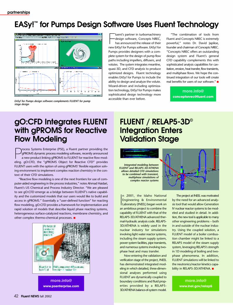
42 Fluent NEWS fall 2002
partnerships
EASy!™ for Pumps Design Software Uses Fluent Technology
Fluent’s partner in turbomachinerydesign software, Concepts NREC,has announced the release of their
new EASy! for Pumps software. EASy! forPumps provides designers with a com-plete system for the design of pump flowpaths including impellers, diffusers, andvolutes. The system integrates meanline,quasi-3D, and CFD analysis to produceoptimized designs. Fluent technologyenables EASy! for Pumps to include theability to design and analyze the volute.Wizard-driven and including optimiza-tion technology, EASy! for Pumps makessophisticated design technology moreaccessible than ever before.
“The combination of tools fromFluent and Concepts NREC is extremelypowerful,” notes Dr. David Japikse,founder and chairman of Concepts NREC.“Concepts NREC offers an outstandingdesign system and Fluent’s generalCFD capability complements this withsophisticated analysis capabilities for cav-itation, erosion, heat transfer, flow transients,and multiphase flows. We hope the con-tinued integration of our tools will createreal benefits for users of our software.” ■
FLUENT / RELAP5-3D©
Integration EntersValidation Stage
In 2001, the Idaho NationalEngineering & EnvironmentalLaboratory (INEEL) began work on
an ambitious project to combine thecapability of FLUENT with that of theRELAP5-3D/ATHENA advanced ther-mal-hydraulic analysis code. RELAP5-3D/ATHENA is widely used in thenuclear industry for simulationsinvolving light water reactor systems,including the steam supply system,power system facilities, pipe transients,and numerous systems involving two-phase heat and mass transfer.
Now entering the validation andverification stage of the project, INEELhas demonstrated integrated mod-eling in which detailed, three-dimen-sional analyses performed usingFLUENT are dynamically coupled toboundary conditions and fluid prop-erties provided by a RELAP5-3D/ATHENA balance-of-system model.
The project at INEEL was motivatedby the need for an advanced analy-sis tool that would allow GenerationIV nuclear reactor systems to be mod-eled and studied in detail. In addi-tion, the new tool is applicable to manyother engineering problems – bothin and outside of the nuclear indus-try. Using the coupled solution, a FLUENT model of a boiler combus-tion chamber might be linked to aRELAP5 model of the steam supplysystem, leveraging RELAP5’s strengthin 1D modeling of boiling and two-phase phenomena. In addition,FLUENT simulations will be linked tothe neutronics/reactor kinetics capa-bility in RELAP5-3D/ATHENA. ■
gO:CFD Integrates FLUENTwith gPROMS for ReactiveFlow Modeling
Process Systems Enterprise (PSE), a Fluent partner providing thegPROMS dynamic process modeling software, recently announceda new product linking gPROMS to FLUENT for reactive flow mod-
eling. gO:CFD, the “gPROMS Object for Reactive CFD” provides FLUENT users with the option of using gPROMS’ flexible equation solv-ing environment to implement complex reaction chemistry in the con-text of their CFD simulations.
“Reactive flow modeling is one of the next frontiers for use of com-puter-aided engineering in the process industries,” notes Ahmad Haidari,Fluent’s US Chemical and Process Industry Director. “We are pleasedto see gO:CFD emerge as a bridge between FLUENT’s native capabil-ity and the customized models that our users would like to build andaccess in gPROMS.” Essentially a “user-defined function” for reactingflow modeling, gO:CFD provides a framework for implementation andrapid solution of models that describe liquid phase reacting systems,heterogeneous surface-catalyzed reactions, membrane chemistry, andother complex thermo-chemical processes. ■
more.info@[email protected]
[email protected]/relap5
EASy! for Pumps design software complements FLUENT for pumpstage design
Integrated modeling betweenFLUENT and RELAP5-3D/ATHENA
allows detailed CFD simulationsto be combined with transient,
multiphase simulations ofcomplex reactor systems

Fluent NEWS fall 2002 43
partnerships
NAFEMS CFD Working Group
NAFEMS – The International Association for theEngineering Analysis Community – is a UK-based,non-profit organization with over 650 members
distributed through 41 countries around the world, main-ly in Europe and North America. Its principal aim is topromote the safe and reliable use of engineering analy-sis (EA) in industry. An important part of its activity isthe provision of training for EA practitioners. It publishesa large number of books containing “how to” guide-lines, benchmark studies, and background informationon EA for the benefit of its members; these books arealso made available for purchase by non-members.
Although best known for its work in solid mechan-ics (especially finite element methods), five years agoNAFEMS established a CFD working group, whose mem-bership includes industrial users of CFD and softwaresuppliers, including Fluent. The group has been work-ing on a number of publications that parallel those produced in the past for finite element analysis, such as:
• Why Do CFD• How To Get Started with CFD• How To Plan a CFD Analysis• How To Understand CFD Jargon
These booklets are targeted at industrial users of CFDand their managers. As the titles suggest, they are focusedon the process of applying CFD, as well as on the tech-nology behind the software and related engineeringscience.
In addition to its publication work, the NAFEMS CFDWorking Party also holds seminars and workshops for mem-bers and non-members. The next, CFD in Industrial TurbulentFlows, will be held in London in February 2003. ■
- C. Carey
QNET – Building Quality and Trust in Industrial CFDBy Chris Carey, Technical Services Manager, Fluent Europe
Fluent is taking part in a four-year European Union R&DThematic Network called
QNET-CFD. The project sets out toassemble, structure and collate infor-mation concerning the performanceof CFD in a wide range of indus-tries. The Network comprises 45 part-ners from the world of CFD(industry, software suppliers, andacademics), collaborating to builda library of CFD knowledge. Thisis how the project works...
Each partner documents a sin-gle Application Challenge – a com-plete, quality-assured industrialstrength test case for which reliableexperimental data are available, toenable validation of CFD models.In each case, the documentationdescribes the problem in sufficientdetail for independent modelers tocalculate the flow using their codeof choice. It also presents the cor-responding experimental data,
and in many cases, a specimen CFDsolution. The Application Challengesare reviewed thoroughly by otherpartners to ensure that they are suit-able for inclusion in the database.Where appropriate, the ApplicationChallenge includes best practicesguidelines for modeling the particularflow conditions.
In addition to the ApplicationChallenges, the partners are alsodeveloping a collection of more fun-damental guidelines for UnderlyingFlow Regimes. These materials doc-ument CFD experience and bestpractices for elemental flows rel-evant to the ApplicationChallenges.
The QNET organi-zation holds an annu-al workshop, opento membersand non-mem-bers
of the project. The next meetingwill be held in Prague in May 2003.Check the website to find out moreabout the work and membershipof QNET-CFD, and obtainelectronic copies of theinformative NetworkNewsletters. ■
Fluent’s Application Challenge inQNET is the cyclone separator

44 Fluent NEWS fall 2002
around Fluent
IMechE Gives First-Ever Award forSoftware to Fluent Europe
April 2002 was anexciting month forthe UK office, as the
prestigious Heritage HallmarkAward from the Institutionof Mechanical Engineers(IMechE) was presented to Fluent Europe for the FLUENT software code.
The IMechE has verystrict criteria for awards, and only gives out two orthree per year. The FLUENT code was recognizedbecause of the significant contribution it has madeto industrial innovation and mechanical engineer-ing over the years. The honor marked the first timethat the Award has been given to a software ven-
dor; previous recipients include organizations thathave produced the Channel Tunnel and Harrier JumpJet, along with well known companies such as RollsRoyce and Eurostar Trains.
Commenting on the award, Fluent Europe’sManaging Director, Chris King said: “I am delightedto see this recognition of the quality and impact of FLUENT CFD software. The Institution of MechanicalEngineers is the UK’s premier Mechanical Engineeringforum and they do not give out these awards lightly.That they should have made the first such award fora software product to FLUENT is all the more special.In doing so, they are recognizing the contribution thatthe efforts of all sections of the Fluent organization havemade to the establishment of CFD as an important engi-neering tool in many industries.” ■
As a worldwide company, Fluent has acknowl-edged the importance of the Benelux market(covering Belgium, the Netherlands, and
Luxembourg) and the dynamic involvement of manylocal companies in CFD. To meet the growing demandsof this community, Fluent opened a Benelux office basedin Wavre, Belgium, close to Brussels, in January 2002.The new office offers opportunities for Fluent staff to workclosely with the local users and develop specific activ-ities of local interest.
Fluent Benelux is one of the oldest Fluent officesin Europe, since it grew out of the Polyflow s.a. com-pany in Louvain-la-Neuve. Indeed, most of the 20
people employed at Fluent Benelux, including a teamof highly qualified PhDs with many years of experi-ence in CFD, were previously employed by Polyflows.a. As a result of its ongoing growth, the local staffrelocated to a new, larger office in Wavre shortly afterofficially becoming Fluent Benelux.
The main activities of the Benelux office addressthe needs of all Fluent software users in the region.This includes software sales, consulting services, tech-nical support, marketing, development, and license administration for the entire suite of Fluent products.In addition, Product Market Management of FIDAPand POLYFLOW software is based in this office. ■
Fluent Benelux Opens in Wavre, Belgium
Fluent WorldwideCorporate headquarters
Fluent Inc.10 Cavendish CourtLebanon, NH 03766, USATel: 603 643 2600Fax: 603 643 3967Email: [email protected]
USA regional officesAnn Arbor, MI 48104Tel: 734 213 6821
Evanston, IL 60201Tel: 847 491 0200
Santa Clara, CA 95051Tel: 408 522 8726
Morgantown, WV 26505Tel: 304 598 3770
European regional officesFluent BeneluxWavre, BelgiumTel: 32 1045 2861Email: [email protected]
Fluent Deutschland GmbHDarmstadt, GermanyTel: 49 6151 36440Email: [email protected]
Fluent Europe Ltd.Sheffield, EnglandTel: 44 114 281 8888Email: [email protected]
Fluent France SAMontigny le Bretonneux, FranceTel: 33 1 3060 9897Email: [email protected]
Fluent ItaliaMilano, ItalyTel: 39 02 8901 3378Email: [email protected]
Fluent Sweden ABGoteborg, Sweden Tel: 46 31 771 8780Email: [email protected]
Asian regional officesFluent Asia Pacific Co., Ltd.Tokyo, JapanTel: 81 3 5324 7301Email: [email protected]
Osaka, JapanTel: 81 6 6445 5690
Fluent India Pvt. Ltd.Pune, IndiaTel: 91 20 6056381Email: [email protected]
DistributorsATES – KoreaBeijing Hi-key Technology
Corporation Ltd. – ChinaCavendish Instruments de Mexico, S.A.
de C.V. (CIM) – Mexico, Venezuela,Argentina, Chile, Columbia
FEM++ – Israel (POLYFLOW only) FIGES Ltd. – Turkey Fluid Codes, Ltd. – UK (serving Middle East) J-ROM – IsraelLEAP Australia Pty., Ltd. – Australia &
New ZealandProcess Flow, Ltd. – FinlandQFINSOFT – South AfricaRCCM – Japan (FIDAP & POLYFLOW only) Scientific Formosa, Inc. – TaiwanSimTec Ltd. – GreeceSMARTtech Services & Systems, Ltd. –
BrazilSymKom – PolandTaiwan Auto-Design Company (TADC)
– Taiwan Techsoft Engineering s.r.o –
Czech Republic
Related Documents