9 Application of Laser-Burnishing Treatment for Improvement of Surface Layer Properties Joanna Radziejewska Institute of Fundamental Technological Research, Polish Academy of Sciences, Warsaw Poland 1. Introduction Laser Beam Machining (LBM) has been successfully applied for improvement of surface layer properties of machine elements. Some of laser treatments are based on melting of surface with a laser beam. Among them is laser hardening, as well as cladding and alloying. The results of broad scope research have shown that surface roughness of elements which underwent the laser melting is too high to apply the process without an additional abrasive machining, even at the optimum parameters of the laser treatment. In most cases after the surface melting with laser beam the tension stresses are observed. That is demonstrated by the cracks in the surface layer and deterioration of its properties (Dietrich Lepski et al., 2009). A new hybrid treatment was elaborated for laser treated materials. The treatment, combining the laser melting with the burnishing process was performed simultaneously at the laser stage. The aim of the hybrid treatment was to reduce surface roughness formed in the laser process and induce compressive stresses. A surface smoothing effect was the result of plastic deformation of the surface layer in high temperature, while a reduction of the tensile stresses within the surface layer was due to cold work (Radziejewska&Skrzypek 2009). For many years the surface burnishing has been used as smoothing and strain hardening finishing. The strain hardening, favourable compressive stress and smooth surface is obtained as a result of plastic deformation of the surface layer of elements made of homogenous material, as well as material with surface layer formed in order to obtain operating properties of superior requirements (Shiou & Hsu, 2008; Milad, 2008). The main limitation of the use of burnishing is high hardness and low plasticity of material after alloying and high roughness of surface. Przybylski, 1987, Shiou & Chen, 2003 showed that as a result of burnishing such materials undergo slight deformation due to the process. Strain hardening degree and thickness of plastic zone are small; cracks often form, whereas expected roughness could not be obtained. For this reason, the process of burnishing is not applied in industry as finishing of layers produced by laser beam. The study (Abbas & West, 1991; Arutunian et al., 1989; Meijer, 2004) demonstrated that modification of surface layers of metals by laser beam - such as hardening, alloying or cladding – provide very hard, resistant to abrasive wear, erosion and corrosion layers. After laser remelting the stresses in the surface layer are generated in accordance with a hot stress model and they are mostly large tensile stresses, leading to the formation of micro- www.intechopen.com

Welcome message from author
This document is posted to help you gain knowledge. Please leave a comment to let me know what you think about it! Share it to your friends and learn new things together.
Transcript

9
Application of Laser-Burnishing Treatment for Improvement of Surface Layer Properties
Joanna Radziejewska Institute of Fundamental Technological Research, Polish Academy of Sciences, Warsaw
Poland
1. Introduction
Laser Beam Machining (LBM) has been successfully applied for improvement of surface layer properties of machine elements. Some of laser treatments are based on melting of surface with a laser beam. Among them is laser hardening, as well as cladding and alloying. The results of broad scope research have shown that surface roughness of elements which underwent the laser melting is too high to apply the process without an additional abrasive machining, even at the optimum parameters of the laser treatment. In most cases after the surface melting with laser beam the tension stresses are observed. That is demonstrated by the cracks in the surface layer and deterioration of its properties (Dietrich Lepski et al., 2009).
A new hybrid treatment was elaborated for laser treated materials. The treatment,
combining the laser melting with the burnishing process was performed simultaneously at
the laser stage. The aim of the hybrid treatment was to reduce surface roughness formed in
the laser process and induce compressive stresses. A surface smoothing effect was the result
of plastic deformation of the surface layer in high temperature, while a reduction of the tensile
stresses within the surface layer was due to cold work (Radziejewska&Skrzypek 2009).
For many years the surface burnishing has been used as smoothing and strain hardening finishing. The strain hardening, favourable compressive stress and smooth surface is obtained as a result of plastic deformation of the surface layer of elements made of homogenous material, as well as material with surface layer formed in order to obtain operating properties of superior requirements (Shiou & Hsu, 2008; Milad, 2008). The main limitation of the use of burnishing is high hardness and low plasticity of material after alloying and high roughness of surface. Przybylski, 1987, Shiou & Chen, 2003 showed that as a result of burnishing such materials undergo slight deformation due to the process. Strain hardening degree and thickness of plastic zone are small; cracks often form, whereas expected roughness could not be obtained. For this reason, the process of burnishing is not applied in industry as finishing of layers produced by laser beam. The study (Abbas & West, 1991; Arutunian et al., 1989; Meijer, 2004) demonstrated that modification of surface layers of metals by laser beam - such as hardening, alloying or cladding – provide very hard, resistant to abrasive wear, erosion and corrosion layers.
After laser remelting the stresses in the surface layer are generated in accordance with a hot stress model and they are mostly large tensile stresses, leading to the formation of micro-
www.intechopen.com
CO2 Laser – Optimisation and Application
252
cracks in extreme cases (Grum & Sturm, 2004; Robinson, 1996) Anthony and Cline 1977 proved theoretically that the surface topography is characterized by relatively high asperities and study (Radziejewska, 2006) where waviness and roughness after laser alloying was examined confirmed this. Such a state of surface implies a need for an additional machining in order to improve surface smoothness.
The classical burnishing process applied after laser treatment was proposed in the works (De Hossonand & Noordhuis 1989, Ignatiev et al. 1993). The reduction of surface roughness and tensile stresses was obtained in the case of thin layer produced by laser alloying of titanium. Ignatiev et al. proposed another solution - the application of classical shot-peening process after laser hardening. As a result of shot-peening the change of stresses, from tensile stresses to compressive, in surface layer 70 µm thick was obtained.
The laser heating process is successfully applied to support the mechanical and plastic working of materials which are difficult for machining. Such a hybrid method was applied for cutting and turning of hard ceramic (Tsai & Ou, 2004). The research on local heating with laser beam during turning, milling and grinding of titanium alloys, cast iron and special steel was conducted. The hybrid treatment - laser-assisted burnishing (LAB) - was elaborated by Tian and Shin 2007. The laser heating process was applied for the burnishing of steel. It provided the reduction of the burnishing force, as well as the tool wear. It was shown that LAB can form better surface roughness and higher hardness than conventional burnishing.
In the work (Radziejewska 2007) the new method to modify surface layer, combing the laser melting with the slide burnishing, was proposed. The smoothing of surface was carried out by plastic deformation of surface layer at high temperature, whereas transformation process of stresses, from compressive to tensile stresses, was performed by plastic deformation at low temperatures. All machining operations - LBM, high and low temperature burnishing - are performed simultaneously on the laser station, in one pass. Temperature changes while the cooling of material that undergoes the laser beam treatment, are used. It does not extend duration of treatment. It was stated that multiple alloying combined with slide burnishing generated compressive stresses of about – 600 MPa at the surface. Because of the adopted type of burnishing – the slide burnishing and high hardness of material, the relatively small thickness of textured zone, about 30 µm, was obtained. In the case of thick layers it can be insufficient. According to (Przybylski, 1987) high degree of strain hardening of surface is possible to provide using dynamic burnishing.
The current work presents the analysis of the plastic deformation of surface layer when the new type of the laser-burnishing process was applied. The surface layer was generated by laser alloying and dynamic burnishing. Design of new head allows for simultaneous surface burnishing in two different temperatures on the laser station providing high-intensity of the burnishing process. That allowed treatment hard and low plasticity materials. Thus such a technical solution should result in high degree of surface deformation as well as its large depth. The proposed solution is designed for thick layers, above 1mm, mostly produced by LBM.
The aim of this study was to evaluate the influence of the hybrid processing parameters on plastic deformations of surface layer and the analysis of the correlations between treatment parameters and surface layer state. Establishing relationships between process parameters and the state of the surface layer of tested material will determine the application area of the
www.intechopen.com
Application of Laser-Burnishing Treatment for Improvement of Surface Layer Properties
253
proposed hybrid treatment for other materials and coatings. Obtaining improved features of surface layer, such as material microstructure, hardening and the compressive stresses, while reducing the amount of surface roughness, will eliminate additional finishing after the laser improving. New features of surface layer affected the basic functional properties of machine parts. Hybrid treatment improved such properties as surface roughness, contact stiffness and erosive wear mainly required in operating condition. It will extend application of the hybrid treatment on cases in which the surface layers have to meet high durability requirements.
2. The experiment description
2.1 Laser alloying
The study was performed using the CO2 laser with the maximum power 2.5 kW. The axially-symmetric beam, of the mode close to TEM10, was focused with use of the ZnSe lens. The focal length of it was 5". The set of treatment parameters, such as laser power, feed rate, and diameter of the beam focused on the metal surface, type of shielding gas and speed of the air flow to ensure a sufficient power density to obtain the remelting and optimal results, was selected. Based on previous experience (Radziejewska&Skrzypek, 2009) the ranges of parameters of laser processing were identified in the first stage of the study. The optimization criteria, such as penetration depth, surface roughness and hardness of the resulting surface layer, were taken into consideration.
The alloying process was carried out on steel 304. Prior to the alloying a layer of Stellite 6, with a thickness of about 200 µm, was formed on the surface with plasma spraying method. Preliminary studies have shown that in this case, the alloying process takes place preferably at the following parameters: laser power 2 kW, laser beam diameter of 3 mm, feed rate of sample against the laser beam from 150-900 mm/min.
2.2 Laser-mechanical treatment
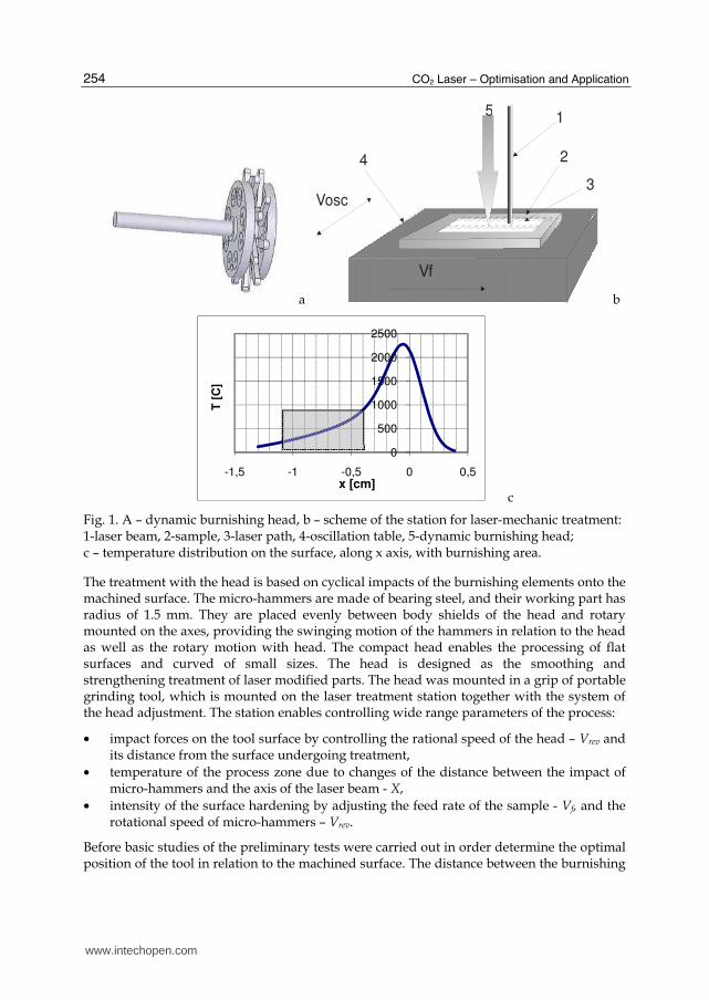
On the laser station the burnishing process was carried out simultaneously with the alloying process. The dynamic burnishing process with use of micro-hammers was applied. The technology of micro-hammering was based on a dynamic centrifugal burnishing. For micro-hammering a high rotational head was developed, providing the possibility of working directly on the laser processing. Processing concept and principle of operation of the head is described in work (Radziejewska et al., 2005). In this study the modified version of the head was applied. Two rows of 8 micro-hammers allow providing greater intensity of the process and the simultaneous treatment at two different temperatures. In order to obtain more uniform deformation of surface material, the oscillation motion of the sample in a direction perpendicular to the direction of feed was introduced. The motion was generated using an oscillating table. The oscillations eliminated the problem of the formation of unfavourable geometric surface structure - the grooves occurring in earlier solution. A constant velocity, of 15 oscillations per second and the amplitude of 2 mm, was used. The small radii of micro-hammers allow to obtained high surface plastic deformation at low forces. The scheme of the head is shown in Figure 1a while the laser-mechanical treatment presented in Fig. 1b. Figure 1c shows the temperature distribution on the surface along x axis with the selected range of temperatures in which the burnishing process was conducted.
www.intechopen.com
CO2 Laser – Optimisation and Application
254
a
1
2
3
4
Vosc
Vf
5
b
c
Fig. 1. A – dynamic burnishing head, b – scheme of the station for laser-mechanic treatment: 1-laser beam, 2-sample, 3-laser path, 4-oscillation table, 5-dynamic burnishing head; c – temperature distribution on the surface, along x axis, with burnishing area.
The treatment with the head is based on cyclical impacts of the burnishing elements onto the machined surface. The micro-hammers are made of bearing steel, and their working part has radius of 1.5 mm. They are placed evenly between body shields of the head and rotary mounted on the axes, providing the swinging motion of the hammers in relation to the head as well as the rotary motion with head. The compact head enables the processing of flat surfaces and curved of small sizes. The head is designed as the smoothing and strengthening treatment of laser modified parts. The head was mounted in a grip of portable grinding tool, which is mounted on the laser treatment station together with the system of the head adjustment. The station enables controlling wide range parameters of the process:
• impact forces on the tool surface by controlling the rational speed of the head – Vrev and its distance from the surface undergoing treatment,
• temperature of the process zone due to changes of the distance between the impact of micro-hammers and the axis of the laser beam - X,
• intensity of the surface hardening by adjusting the feed rate of the sample - Vf, and the rotational speed of micro-hammers – Vrev.
Before basic studies of the preliminary tests were carried out in order determine the optimal position of the tool in relation to the machined surface. The distance between the burnishing
0
500
1000
1500
2000
2500
-1,5 -1 -0,5 0 0,5
T [
C]
x [cm]
www.intechopen.com
Application of Laser-Burnishing Treatment for Improvement of Surface Layer Properties
255
element and the laser beam axis was determined initially on the basis of calculations of temperature distribution on material surface, when a moving source of heat, which has a Gaussian distribution of energy density, was considered. The distribution in a half-space has an approximate character because of numerous simplified assumptions (Anthony&Cline, 1977). The distribution in a half-space has an approximate character because of following simplified assumptions:
- material properties, such as heat conduction, density, specific heat and coefficient of reflection are constant and temperature independent,
- there is no loss of energy, - heat of phase transformation is not taken into consideration, - convectional heat transfer in liquid metal is not considered.
The calculations were done for parameters of laser treatment, the same as those were applied in preliminary investigations. The results of calculations have been verified by microstructure changes of material. The tools interacted with material within temperature range about 200–8500C.
2.3 Testing methods
Study of surface layer state is time-consuming. Therefore determination the effect of treatment conditions on the state of surface layer was based on the theory of planned experiment, which minimizes the number of studies (Filipowski 1996; Montgomery, 1997). An experiment based on a static, determined, multi-factorial, rotatable planned program
with repetition PS/DS- λ was carried out. The aim was to find functional relations between the parameters of the hybrid treatment and the state of the surface layer.
The selection of input variables and ranges of their variation was based on preliminary results of the laser- mechanical process taking their suitability to control the hybrid treatment as an additional criterion. As the measurable, controllable input variables the following quantities were considered:
- distance between the head and the laser beam axis (X) that determines the temperature of the burnishing process,
- rotational speed of the burnishing head (Vrev); the parameter affects the impact force of hammers on the surface,
- feed rate of the sample (Vf), which contributes both to the intensity of the burnishing process and temperature in the region of treatment.
As the output factors characterizing the state of surface layer and the effects of hybrid treatment were: change in microhardness compared to the microhardness after laser alloying, thickness of the plastic deformation zones and the ratio of thickness of the plastic deformation zones to thickness of alloyed zone. On the basis of preliminary studies the areas of treatment parameters variability and the intervals of variation of input data were determined. Indications and values of variation ranges of input data are contained in Table 1.
The statistical analysis of experimental results included a selection of the regression function, a statistical verification of the approximating function adequacy and verification of significance of the approximating function coefficients. The attempts of approximation using the power function and the first-degree polynomial have been made. The correlation
www.intechopen.com
CO2 Laser – Optimisation and Application
256
and significance evaluation has been determined according to criteria based on I. P. Guilford theory. The confidence level α = 0.1 was adopted. Credibility of the equations was assessed based on the following criteria: - critical value of the F-statistic, Fkr = 2.71, - critical value of the T-Student coefficients, Tkr = 1.41 for α = 0.1.
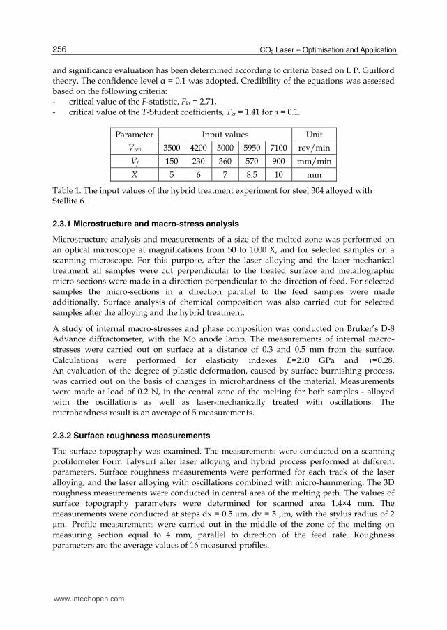
Parameter Input values Unit
Vrev 3500 4200 5000 5950 7100 rev/min
Vf 150 230 360 570 900 mm/min
X 5 6 7 8,5 10 mm
Table 1. The input values of the hybrid treatment experiment for steel 304 alloyed with Stellite 6.
2.3.1 Microstructure and macro-stress analysis
Microstructure analysis and measurements of a size of the melted zone was performed on an optical microscope at magnifications from 50 to 1000 X, and for selected samples on a scanning microscope. For this purpose, after the laser alloying and the laser-mechanical treatment all samples were cut perpendicular to the treated surface and metallographic micro-sections were made in a direction perpendicular to the direction of feed. For selected samples the micro-sections in a direction parallel to the feed samples were made additionally. Surface analysis of chemical composition was also carried out for selected samples after the alloying and the hybrid treatment.
A study of internal macro-stresses and phase composition was conducted on Bruker’s D-8 Advance diffractometer, with the Mo anode lamp. The measurements of internal macro-stresses were carried out on surface at a distance of 0.3 and 0.5 mm from the surface.
Calculations were performed for elasticity indexes E=210 GPa and ν=0.28. An evaluation of the degree of plastic deformation, caused by surface burnishing process, was carried out on the basis of changes in microhardness of the material. Measurements were made at load of 0.2 N, in the central zone of the melting for both samples - alloyed with the oscillations as well as laser-mechanically treated with oscillations. The microhardness result is an average of 5 measurements.
2.3.2 Surface roughness measurements
The surface topography was examined. The measurements were conducted on a scanning profilometer Form Talysurf after laser alloying and hybrid process performed at different parameters. Surface roughness measurements were performed for each track of the laser alloying, and the laser alloying with oscillations combined with micro-hammering. The 3D roughness measurements were conducted in central area of the melting path. The values of surface topography parameters were determined for scanned area 1.4×4 mm. The measurements were conducted at steps dx = 0.5 µm, dy = 5 µm, with the stylus radius of 2 µm. Profile measurements were carried out in the middle of the zone of the melting on measuring section equal to 4 mm, parallel to direction of the feed rate. Roughness parameters are the average values of 16 measured profiles.
www.intechopen.com
Application of Laser-Burnishing Treatment for Improvement of Surface Layer Properties
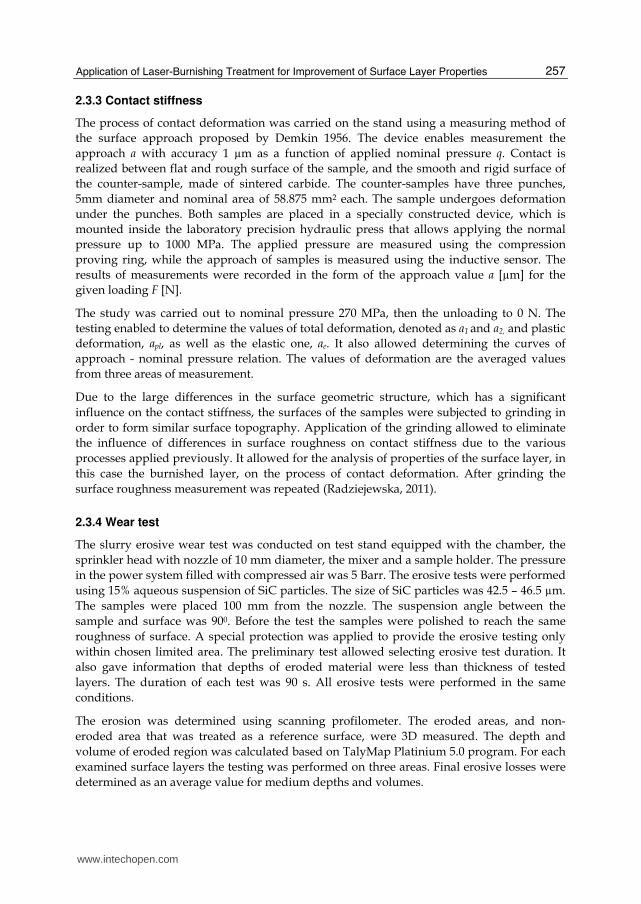
257
2.3.3 Contact stiffness
The process of contact deformation was carried on the stand using a measuring method of
the surface approach proposed by Demkin 1956. The device enables measurement the
approach a with accuracy 1 µm as a function of applied nominal pressure q. Contact is
realized between flat and rough surface of the sample, and the smooth and rigid surface of
the counter-sample, made of sintered carbide. The counter-samples have three punches,
5mm diameter and nominal area of 58.875 mm2 each. The sample undergoes deformation
under the punches. Both samples are placed in a specially constructed device, which is
mounted inside the laboratory precision hydraulic press that allows applying the normal
pressure up to 1000 MPa. The applied pressure are measured using the compression
proving ring, while the approach of samples is measured using the inductive sensor. The
results of measurements were recorded in the form of the approach value a [µm] for the
given loading F [N].
The study was carried out to nominal pressure 270 MPa, then the unloading to 0 N. The
testing enabled to determine the values of total deformation, denoted as a1 and a2, and plastic
deformation, apl, as well as the elastic one, ae. It also allowed determining the curves of
approach - nominal pressure relation. The values of deformation are the averaged values
from three areas of measurement.
Due to the large differences in the surface geometric structure, which has a significant
influence on the contact stiffness, the surfaces of the samples were subjected to grinding in
order to form similar surface topography. Application of the grinding allowed to eliminate
the influence of differences in surface roughness on contact stiffness due to the various
processes applied previously. It allowed for the analysis of properties of the surface layer, in
this case the burnished layer, on the process of contact deformation. After grinding the
surface roughness measurement was repeated (Radziejewska, 2011).
2.3.4 Wear test
The slurry erosive wear test was conducted on test stand equipped with the chamber, the
sprinkler head with nozzle of 10 mm diameter, the mixer and a sample holder. The pressure
in the power system filled with compressed air was 5 Barr. The erosive tests were performed
using 15% aqueous suspension of SiC particles. The size of SiC particles was 42.5 – 46.5 µm.
The samples were placed 100 mm from the nozzle. The suspension angle between the
sample and surface was 900. Before the test the samples were polished to reach the same
roughness of surface. A special protection was applied to provide the erosive testing only
within chosen limited area. The preliminary test allowed selecting erosive test duration. It
also gave information that depths of eroded material were less than thickness of tested
layers. The duration of each test was 90 s. All erosive tests were performed in the same
conditions.
The erosion was determined using scanning profilometer. The eroded areas, and non-
eroded area that was treated as a reference surface, were 3D measured. The depth and
volume of eroded region was calculated based on TalyMap Platinium 5.0 program. For each
examined surface layers the testing was performed on three areas. Final erosive losses were
determined as an average value for medium depths and volumes.
www.intechopen.com
CO2 Laser – Optimisation and Application
258
3. Plastic deformations due to laser-burnishing
3.1 Microstructure and size of plastic deformation zone
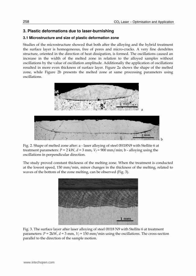
Studies of the microstructure showed that both after the alloying and the hybrid treatment the surface layer is homogeneous, free of pores and micro-cracks. A very fine dendrites structure, oriented in the direction of heat dissipation, is formed. The oscillations caused an increase in the width of the melted zone in relation to the alloyed samples without oscillations by the value of oscillation amplitude. Additionally the application of oscillations resulted in more even thickness of surface layer. Figure 2a shows the shape of the melted zone, while Figure 2b presents the melted zone at same processing parameters using oscillations.
a
b
Fig. 2. Shape of melted zone after: a - laser alloying of steel 0H18N9 with Stellite 6 at treatment parameters: P = 2 kW, d = 3 mm, Vf = 900 mm/min; b - alloying using the oscillations in perpendicular direction.
The study proved constant thickness of the melting zone. When the treatment is conducted at the lowest speed, 150 mm/min, minor changes in the thickness of the melting, related to waves of the bottom of the zone melting, can be observed (Fig. 3).
Fig. 3. The surface layer after laser alloying of steel 0H18 N9 with Stellite 6 at treatment parameters: P = 2kW, d = 3 mm, Vf = 150 mm/min using the oscillations. The cross-section parallel to the direction of the sample motion.
www.intechopen.com

Application of Laser-Burnishing Treatment for Improvement of Surface Layer Properties
259
Surface plastic deformation caused a complete reconstruction of material microstructure
near the surface. The microstructure, after laser alloying, is shown in Figure 4. There are
equiaxed grains of a size of several micrometers. The intensive flattening of grains in the
direction perpendicular to the surface is presented, Fig.5. There are no cracks or chipping.
The coating particles, which were not melted by laser, can be observed on the surface in
some places. They were probably stuck in the surface of already melted and solidified
material by the micro-hammers. The largest deformation of grains is in the zone about 100-
150 µm from the surface. As it was expected the varied plastic deformation thickness of the
zone was determined depending on the impact of the micro-hammers on the surface and the
temperature at which the process was carried out.
a b
Fig. 4. The surface layer microstructure of steel 0H18N9 after laser alloying with Stellite 6 using oscillations; a- close to surface, b- central part of alloyed zone. The treatment parameters: P = 2kW, d = 3 mm, Vf = 230 mm/min; (SEM).
a b
Fig. 5. The surface layer microstructure after hybrid treatment at the parameters: P = 2kW, d = 3 mm, Vf = 230 mm/min, V rev= 5950 rev/min, X = 6 mm, using oscillations; a- close to surface, b- central part of alloyed zone; (SEM).
The X –ray diffraction XRD showed the presence of cobalt austenite, tungsten carbides and chromium as well as chromium oxides, cobalt and cobalt ferrite. In almost all samples the dominant phase was cobalt austenite. The analysis of chemical composition in the melting
www.intechopen.com
CO2 Laser – Optimisation and Application
260
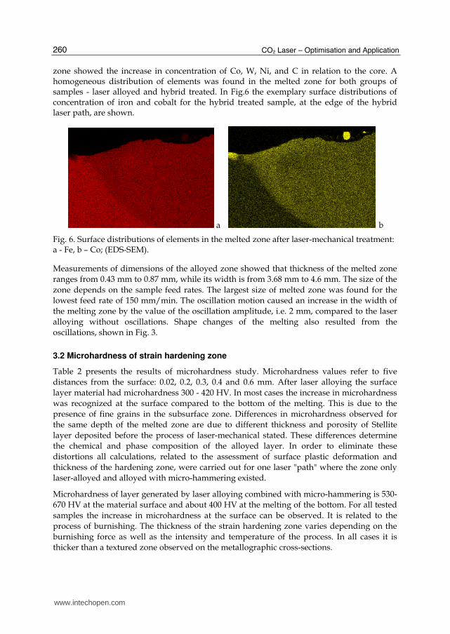
zone showed the increase in concentration of Co, W, Ni, and C in relation to the core. A homogeneous distribution of elements was found in the melted zone for both groups of samples - laser alloyed and hybrid treated. In Fig.6 the exemplary surface distributions of concentration of iron and cobalt for the hybrid treated sample, at the edge of the hybrid laser path, are shown.
a b
Fig. 6. Surface distributions of elements in the melted zone after laser-mechanical treatment: a - Fe, b – Co; (EDS-SEM).
Measurements of dimensions of the alloyed zone showed that thickness of the melted zone
ranges from 0.43 mm to 0.87 mm, while its width is from 3.68 mm to 4.6 mm. The size of the
zone depends on the sample feed rates. The largest size of melted zone was found for the
lowest feed rate of 150 mm/min. The oscillation motion caused an increase in the width of
the melting zone by the value of the oscillation amplitude, i.e. 2 mm, compared to the laser
alloying without oscillations. Shape changes of the melting also resulted from the
oscillations, shown in Fig. 3.
3.2 Microhardness of strain hardening zone
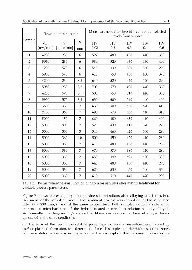
Table 2 presents the results of microhardness study. Microhardness values refer to five
distances from the surface: 0.02, 0.2, 0.3, 0.4 and 0.6 mm. After laser alloying the surface
layer material had microhardness 300 - 420 HV. In most cases the increase in microhardness
was recognized at the surface compared to the bottom of the melting. This is due to the
presence of fine grains in the subsurface zone. Differences in microhardness observed for
the same depth of the melted zone are due to different thickness and porosity of Stellite
layer deposited before the process of laser-mechanical stated. These differences determine
the chemical and phase composition of the alloyed layer. In order to eliminate these
distortions all calculations, related to the assessment of surface plastic deformation and
thickness of the hardening zone, were carried out for one laser "path" where the zone only
laser-alloyed and alloyed with micro-hammering existed.
Microhardness of layer generated by laser alloying combined with micro-hammering is 530-
670 HV at the material surface and about 400 HV at the melting of the bottom. For all tested
samples the increase in microhardness at the surface can be observed. It is related to the
process of burnishing. The thickness of the strain hardening zone varies depending on the
burnishing force as well as the intensity and temperature of the process. In all cases it is
thicker than a textured zone observed on the metallographic cross-sections.
www.intechopen.com
Application of Laser-Burnishing Treatment for Improvement of Surface Layer Properties
261
Sample
Treatment parameter Microhardness after hybrid treatment at selected
levels from surface
Vrev
[rev/min]Vf
[mm/min]
X HV 0.02
HV 0.2
HV 0.3
HV 0.4
HV 0.6 [mm]
1 4200 230 6 527 480 430 410 350
2 5950 230 6 530 520 460 430 400
3 4200 570 6 540 430 380 360 290
4 5950 570 6 610 550 480 450 370
5 4200 230 8,5 640 520 440 420 290
6 5950 230 8,5 700 570 490 440 360
7 4200 570 8,5 580 550 510 440 350
8 5950 570 8,5 630 600 540 440 400
9 3500 360 7 630 500 560 520 410
10 7100 360 7 680 570 460 410 310
11 5000 150 7 660 480 450 410 400
12 5000 900 7 570 430 410 370 270
13 5000 360 5 540 460 420 380 290
14 5000 360 10 500 450 420 410 280
15 5000 360 7 610 480 430 410 280
16 5000 360 7 670 570 380 410 280
17 5000 360 7 630 490 490 420 380
18 5000 360 7 640 480 430 410 290
19 5000 360 7 620 530 450 400 350
20 5000 360 7 610 510 440 420 290
Table 2. The microhardness as function of depth for samples after hybrid treatment for variable process parameters.
Figure 7 shows the exemplary microhardness distributions after alloying and the hybrid treatment for the samples 1 and 2. The treatment process was carried out at the same feed rate, Vf = 230 mm/s, and at the same temperature. Both samples exhibit a substantial increase in microhardness of the hybrid treated material in relation to only alloyed. Additionally, the diagram Fig.7 shows the differences in microhardness of alloyed layers generated in the same conditions.
On the basis of the results the relative percentage increase in microhardness, caused by surface plastic deformation, was determined for each sample, and the thickness of the zones of plastic deformation was estimated under the assumption that minimal increase in the
www.intechopen.com

CO2 Laser – Optimisation and Application
262
layer is 10% (Tab.3). The micro-hammering caused the relative increase in microhardness of SL of about 32-100% at the surface compared to microhardness of SL due to laser alloying. This effect is due to surface strain hardening. The smallest increase in microhardness, 32%, at the surface was found for the sample that was burnished at the lowest temperature when distance between the hammers and the beam axis was 10 mm. In this case, the smallest depth of the plastic deformation zone was also recognized. The increase in microhardness, over 60%, was found for most of the samples (2, 4, 5, 6, 10, 11, 15-20) burnished with large impact forces of micro-hammers on surface, rotational speeds of the head above 5000 rev/min and temperature of treatment from the middle range. For the samples (1, 13) burnished at high temperature the degree of strain hardening is the order of 40-50%, which is probably related to the partial recovery of the material at high temperature.
0
100
200
300
400
500
600
0 0,2 0,4 0,6 0,8 1 1,2 1,4
HV
0.0
2
distance from surface [mm]
Fig. 7. Microhardness after: ♦ ■ laser alloying of steel 0H18 N9 with Stellite 6 treatment parameters: P = 2 kW, d = 3 mm, Vf = 230 mm/min and alloying combined with micro-hammering ▲ X = 6 mm, Vrev= 4200 rev/min, × Vrev= 5950 rev/min,
The thickness of the plastic deformation zone is from 0.25 to 1.2 mm, depending on the parameters of laser-mechanical treatment. It grows with increase of the impact forces of burnishing elements on the surface and the rise of temperature in which the process of burnishing was undergoing. This effect is due to the increase in material plasticity with temperature growth.
Plastic deformation of the surface layer caused changes in residual stresses. In order to assess the state of stresses in the surface layer the preliminary studies of internal macro-stresses were performed. The selected for study samples were laser alloyed at feed rate of 230 mm/min and dynamically burnished at temperature from the upper range, Vrev = 5950 rev/min, X = 6 mm. The measurements were carried out on the surface and at the depth of 0.3 and 0.5 mm beneath the surface. The results confirmed the stresses change, from tensile +398 MPa after the alloying process to compressive stresses -800 MPa caused by the burnishing process. After the dynamic burnishing the compressive stresses across the whole depth of the melted zone were found.
www.intechopen.com
Application of Laser-Burnishing Treatment for Improvement of Surface Layer Properties
263
Sample
Treatment parameter Relative change in microhardness [%]
Thickness of plastic deformation zone
[mm]
Gpl/Gla Vrev
[rev/min]Vf
[mm/min]
X HV 0.02
HV 0.2
HV 0.3
HV 0.4
HV 0.6 [mm]
1 4200 230 6 46 45 34 28 9 0.55 0.75
2 5950 230 6 71 63 44 43 38 1.2 1.62
3 4200 570 6 59 13 0 0 0 0.25 0.54
4 5950 570 6 74 67 60 50 42 1.2 2.67
5 4200 230 8.5 78 30 13 14 - 0.5 0.77
6 5950 230 8.5 89 36 32 16 38 0.7 1.08
7 4200 570 8.5 32 45 34 10 - 0.4 0.75
8 5950 570 8.5 50 43 32 13 14 0.65 1.30
9 3500 360 7 62 39 56 33 8 0.5 0.94
10 7100 360 7 100 68 53 37 3 0.55 1.00
11 5000 150 7 89 55 50 37 33 1.1 1.26
12 5000 900 7 68 39 24 12 4 0.45 1.05
13 5000 360 5 54 44 35 27 - 0.5 0.77
14 5000 360 10 32 18 2 8 4 0.25 0.43
15 5000 360 7 74 41 23 28 - 0.5 0.88
16 5000 360 7 91 78 9 17 - 0.4 0.67
17 5000 360 7 70 29 32 17 12 0.55 0.80
18 5000 360 7 83 41 23 28 - 0.5 0.82
19 5000 360 7 77 66 29 14 3 0.5 0.85
20 5000 360 7 65 34 19 17 - 0.5 0.74
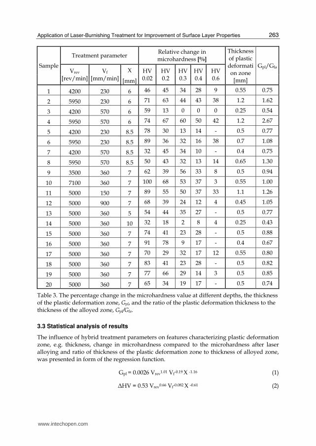
Table 3. The percentage change in the microhardness value at different depths, the thickness of the plastic deformation zone, Gpl, and the ratio of the plastic deformation thickness to the thickness of the alloyed zone, Gpl/Gla.
3.3 Statistical analysis of results
The influence of hybrid treatment parameters on features characterizing plastic deformation zone, e.g. thickness, change in microhardness compared to the microhardness after laser alloying and ratio of thickness of the plastic deformation zone to thickness of alloyed zone, was presented in form of the regression function.
Gpl = 0.0026 Vrev1.01 Vf-0.19 X -1.16 (1)
ΔHV = 0.53 Vrev0.66 Vf-0.082 X -0.61 (2)
www.intechopen.com

CO2 Laser – Optimisation and Application
264
Gpl/Gla = 0.00035 Vrev1.02 Vf0.2 X -1.09 (3)
Table 4 contains the value of multiple correlation coefficients R, the value of the Fisher’s number F and T-Student coefficient describing the significance of subsequent independent variables T1, T2, T3, and T4.
Relation R F T1 T2 T3
1 0.78 8.4 3.15 1.5 3.59
2 0.68 4.6 2.65 0.85 2.45
3 0.74 6.3 2.81 1.46 2.97
Table 4. The regression function for the thickness of the plastic deformation zone, Gpl, change in microhardness ,ΔHV, and ratio of thickness of the plastic deformation zones to thickness of alloyed zone Gpl/Gla of hybrid treated steel 304.
Multiple correlation coefficients of the equations are high and the relation between the studied properties is significant. For all equations, the condition F > Fkr is fulfilled. For the first and third equations all the factors are significant t > tkr at confidence level α = 0.1. Only in the case of the function 2 which shows the relation of the microhardness increase the factor T2 describing influence of feed rate is insignificant for the assumed level of confidence.
Figure 8 shows the graphical interpretation of the thickness of strain hardening depending on the rotational speed of the burnishing head and the distance between the tool from the axis of the laser beam for fixed feed rate, Vf = 360 mm/s, according to the relation 1, Table 4. The strain hardening thickness almost linearly increases with speed growing and decreases with increasing distance from the axis. With increasing of the head rotational speed the intensity of the burnishing process and the impact forces of micro-hammers on machined surface increases. It induced an enlargement of the plastic deformation depth of the material in the entire range of temperatures applied in the burnishing. The effect of temperature on the depth of the plastic deformation zone is stronger for raised values of the impact forces and higher intensity of the burnishing process.
Fig. 8. Effect of rotational speed and the distance between laser beam and the head on the thickness plastic deformation zone at fixed feed rate, Vf = 360 mm/min.
www.intechopen.com
Application of Laser-Burnishing Treatment for Improvement of Surface Layer Properties
265
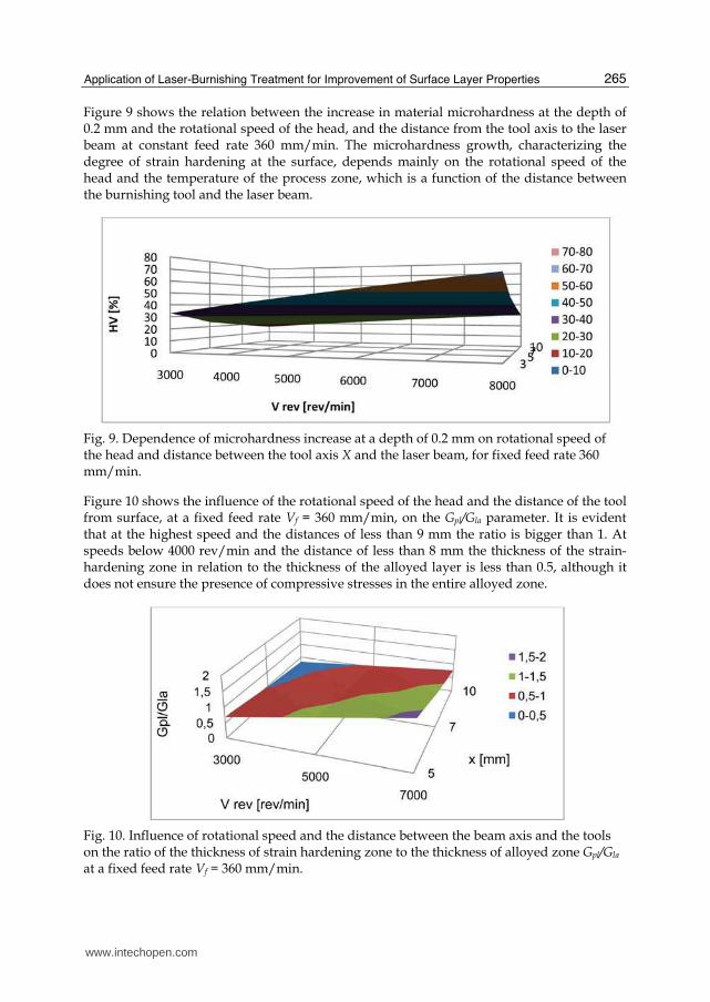
Figure 9 shows the relation between the increase in material microhardness at the depth of 0.2 mm and the rotational speed of the head, and the distance from the tool axis to the laser beam at constant feed rate 360 mm/min. The microhardness growth, characterizing the degree of strain hardening at the surface, depends mainly on the rotational speed of the head and the temperature of the process zone, which is a function of the distance between the burnishing tool and the laser beam.
Fig. 9. Dependence of microhardness increase at a depth of 0.2 mm on rotational speed of the head and distance between the tool axis X and the laser beam, for fixed feed rate 360 mm/min.
Figure 10 shows the influence of the rotational speed of the head and the distance of the tool from surface, at a fixed feed rate Vf = 360 mm/min, on the Gpl/Gla parameter. It is evident that at the highest speed and the distances of less than 9 mm the ratio is bigger than 1. At speeds below 4000 rev/min and the distance of less than 8 mm the thickness of the strain-hardening zone in relation to the thickness of the alloyed layer is less than 0.5, although it does not ensure the presence of compressive stresses in the entire alloyed zone.
Fig. 10. Influence of rotational speed and the distance between the beam axis and the tools on the ratio of the thickness of strain hardening zone to the thickness of alloyed zone Gpl/Gla at a fixed feed rate Vf = 360 mm/min.
www.intechopen.com
CO2 Laser – Optimisation and Application
266
4. Surface roughness after hybrid treatment
4.1 Surface topography
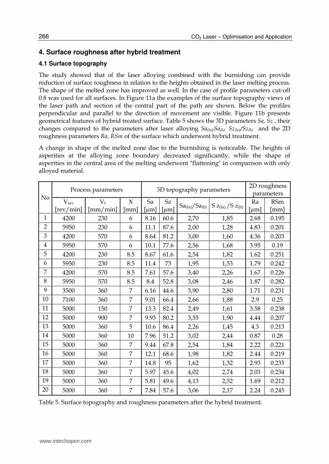
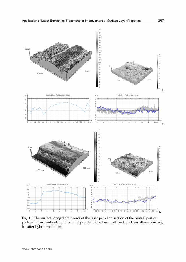
The study showed that of the laser alloying combined with the burnishing can provide reduction of surface roughness in relation to the heights obtained in the laser melting process. The shape of the melted zone has improved as well. In the case of profile parameters cut-off 0.8 was used for all surfaces. In Figure 11a the examples of the surface topography views of the laser path and section of the central part of the path are shown. Below the profiles perpendicular and parallel to the direction of movement are visible. Figure 11b presents geometrical features of hybrid treated surface. Table 5 shows the 3D parameters Sa, Sz , their changes compared to the parameters after laser alloying Sa(la)/Sa(h), Sz(la)/Sz(h) and the 2D roughness parameters Ra, RSm of the surface which underwent hybrid treatment.
A change in shape of the melted zone due to the burnishing is noticeable. The heights of asperities at the alloying zone boundary decreased significantly, while the shape of asperities in the central area of the melting underwent "flattening" in comparison with only alloyed material.
No
Process parameters 3D topography parameters 2D roughness
parameters
Vrev [rev/min]
Vf
[mm/min]X
[mm]Sa
[µm]Sz
[µm]Sa(la)/Sa(h) S z(la) /S z(h)
Ra [µm]
RSm [mm]
1 4200 230 6 8.16 60.6 2,70 1,85 2.68 0.195
2 5950 230 6 11.1 87.6 2,00 1,28 4.83 0.201
3 4200 570 6 8.64 81.2 3,00 1,60 4.36 0.203
4 5950 570 6 10.1 77.6 2,56 1,68 3.95 0.19
5 4200 230 8.5 8.67 61.6 2,54 1,82 1.62 0.251
6 5950 230 8.5 11.4 73 1,95 1,53 1.79 0.242
7 4200 570 8.5 7.61 57.6 3,40 2,26 1.67 0.226
8 5950 570 8.5 8.4 52.8 3,08 2,46 1.87 0.282
9 3500 360 7 6.16 44.6 3,90 2,80 1.71 0.231
10 7100 360 7 9.01 66.4 2,66 1,88 2.9 0.25
11 5000 150 7 13.3 82.4 2,49 1,61 3.58 0.238
12 5000 900 7 9.93 80.2 3,55 1,90 4.44 0.207
13 5000 360 5 10.6 86.4 2,26 1,45 4.3 0.213
14 5000 360 10 7.96 51.2 3,02 2,44 0.87 0.28
15 5000 360 7 9.44 67.8 2,54 1,84 2.22 0.221
16 5000 360 7 12.1 68.6 1,98 1,82 2.44 0.219
17 5000 360 7 14.8 95 1,62 1,32 2.93 0.235
18 5000 360 7 5.97 45.6 4,02 2,74 2.03 0.234
19 5000 360 7 5.81 49.6 4,13 2,52 1.69 0.212
20 5000 360 7 7.84 57.6 3,06 2,17 2.24 0.245
Table 5. Surface topography and roughness parameters after the hybrid treatment.
www.intechopen.com
Application of Laser-Burnishing Treatment for Improvement of Surface Layer Properties
267
a
a
b
Fig. 11. The surface topography views of the laser path and section of the central part of path, and perpendicular and parallel profiles to the laser path and: a – laser alloyed surface, b – after hybrid treatment.
µm
-150
-100
-50
0
50
100
0 0.2 0.4 0.6 0.8 1 1.2 1.4 1.6 1.8 2 2.2 2.4 2.6 2.8 3 3.2 mm
Length = 3.23 mm Pt = 168 µm Scale = 300 µm µm
-40
-30
-20
-10
0
10
20
30
40
50
0 0.5 1 1.5 2 2.5 3 3.5 4 4.5 mm
Profile # 1 / 16 Pt = 38 µm Scale = 100 µm
µm
-250
-200
-150
-100
-50
0
50
100
0 0.5 1 1.5 2 2.5 3 3.5 4 4.5 mm
Length = 4.66 mm Pt = 255 µm Scale = 400 µm µm
-30
-20
-10
0
10
20
30
40
50
60
0 0.2 0.4 0.6 0.8 1 1.2 1.4 1.6 1.8 2 2.2 2.4 2.6 2.8 3 3.2 3.4 3.6 3.8 4 mm
Profile # 1 / 11 Pt = 33.6 µm Scale = 100 µm
www.intechopen.com
CO2 Laser – Optimisation and Application
268
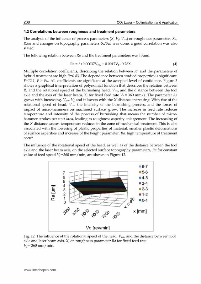
4.2 Correlations between roughness and treatment parameters
The analysis of the influence of process parameters (X, Vf, Vrev) on roughness parameters Ra,
RSm and changes on topography parameters Sz/Szh was done, a good correlation was also
stated.
The following relation between Ra and the treatment parameters was found:
Ra = 6+0.00037Vrev + 0.0017Vf - 0.76X (4)
Multiple correlation coefficients, describing the relation between Ra and the parameters of
hybrid treatment are high R=0.83. The dependence between studied properties is significant:
F=12.1, F > Fkr. All coefficients are significant at the accepted level of confidence. Figure 3
shows a graphical interpretation of polynomial function that describes the relation between
Ra and the rotational speed of the burnishing head, Vrev, and the distance between the tool
axle and the axis of the laser beam, X, for fixed feed rate Vf = 360 mm/s. The parameter Ra
grows with increasing, Vrev, Vf, and it lowers with the X distance increasing. With rise of the
rotational speed of head, Vrev, the intensity of the burnishing process, and the forces of
impact of micro-hammers on machined surface, grow. The increase in feed rate reduces
temperature and intensity of the process of burnishing that means the number of micro-
hammer strokes per unit area, leading to roughness asperity enlargement. The increasing of
the X distance causes temperature reduces in the zone of mechanical treatment. This is also
associated with the lowering of plastic properties of material, smaller plastic deformations
of surface asperities and increase of the height parameter, Ra. high temperature of treatment
occur.
The influence of the rotational speed of the head, as well as of the distance between the tool
axle and the laser beam axis, on the selected surface topography parameters, Ra for constant
value of feed speed Vf =360 mm/min, are shown in Figure 12.
Fig. 12. The influence of the rotational speed of the head, Vrev, and the distance between tool axle and laser beam axis, X, on roughness parameter Ra for fixed feed rate Vf = 360 mm/min.
www.intechopen.com
Application of Laser-Burnishing Treatment for Improvement of Surface Layer Properties
269
When analyzing the influence of process parameters on roughness sampling, RSm, a good correlation was also stated; R=0.82, F=11.3.Polynomial function, for which all the coefficients of the equation are significant at the confidence level of 0.1, shows good fit.
RSm = 0.085-0.000004 Vrev+ 0.00002 Vf + 0.017 X (5)
With an increase in the rotational speed of the head the roughness spacing decreases, while the increasing distance between the head and the laser beam and in the feed rate, causes lowering of RSm. Analysis of the equation shows that the rise of temperature of the burnishing process affects the spatial property of surface geometrical structure increasing the distance between micro-asperities.
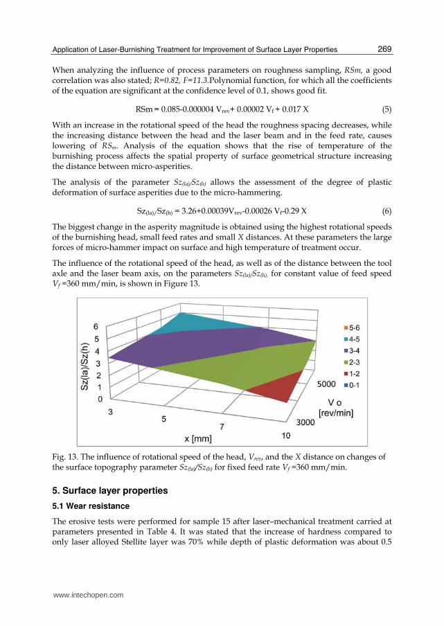
The analysis of the parameter Sz(la)/Sz(h) allows the assessment of the degree of plastic deformation of surface asperities due to the micro-hammering.
Sz(la)/Sz(h) = 3.26+0.00039Vrev-0.00026 Vf-0.29 X (6)
The biggest change in the asperity magnitude is obtained using the highest rotational speeds of the burnishing head, small feed rates and small X distances. At these parameters the large forces of micro-hammer impact on surface and high temperature of treatment occur.
The influence of the rotational speed of the head, as well as of the distance between the tool axle and the laser beam axis, on the parameters Sz(la)/Sz(h), for constant value of feed speed Vf =360 mm/min, is shown in Figure 13.
Fig. 13. The influence of rotational speed of the head, Vrev, and the X distance on changes of the surface topography parameter Sz(la)/Sz(h) for fixed feed rate Vf =360 mm/min.
5. Surface layer properties
5.1 Wear resistance
The erosive tests were performed for sample 15 after laser–mechanical treatment carried at parameters presented in Table 4. It was stated that the increase of hardness compared to only laser alloyed Stellite layer was 70% while depth of plastic deformation was about 0.5
www.intechopen.com

CO2 Laser – Optimisation and Application
270
mm. The tests were done also for the plasma sprayed Stellite 6 layer and the layer formed by laser alloying at feed rate 360 mm/min.
Fig. 14. The profiles after erosive wear test: PS-plasma sprayed Stellite 6 layer, LA- laser alloyed layer (P=2 kW, d=3 mm Vf =360 mm/min), Hybrid - sample 13 after laser-mechanical treatment (P=2 kW, d=2.5 mm Vf =360 mm/min, Vrev = 5000 rev/min, X = 5 mm).
Figure 5 shows exemplary surface profiles after erosive wear after laser-mechanical treatment, laser alloying and plasma sprayed Stellite 6 layer. The eroded surface is visible in the middle. The non-eroded side material parts were used as the reference surface. The profiles of examined surfaces show significant differences in erosive depth. The maximal depth was smaller than the thickness of tested layers. The measurement of surface topography was performed on three selected areas and the medium depth and volume per 1 mm2 was chosen for quantitative analysis. This allowed compare erosive wear resistance of different surface layers of Stellite 6. Table 6 contains the average value of depth and volume of eroded surfaces whereas Figure 5 presents average eroded materials volumes loss.
Among Stellite 6 layers produced by plasma spraying, laser alloying and laser alloying combined with burnishing; the surfaces after hybrid treatment had the highest resistance to slurry erosive wear. The examined surfaces after laser-mechanical treatment showed the average depth of erosive loss 16.2µm. Surfaces after laser alloying showed little less of erosive resistance, 13-30 %, than hybrid treated surfaces. Their erosive depth was 22 µm.
The largest erosive loss was stated for plasma sprayed Stellite 6 layer, for which the average depth was 82 µm. Its erosive resistance is five times worse than the one of hybrid treated layer.
Treatment The depth of erosive loss
[µm] The volume of loss
[mm3]
Laser alloying 22.2 0.0992
Hybrid treatment 16.2 0.0699
Plasma spraying 81.9 0.3621
Table 6. The average depth and volume of erosive losses of Stellite 6 layer after slurry erosive test
www.intechopen.com

Application of Laser-Burnishing Treatment for Improvement of Surface Layer Properties
271
5.2 Contact stiffness
The results of contact strain and contact stiffness are shown in Table. The analysis of the total value of elastic and plastic strain shows that the surfaces after the burnishing undergo significantly lower elastic and plastic deformation in contact with counter sample. For samples without grinding this effect is associated primarily with surface topography. In the process of burnishing the rebuilding of surface topography occurs: surface irregularities have smaller heights, while their shapes become preferable. Therefore, the real contact area is increased and the unit pressure on individual asperities is reduced. At nominal pressure
of 270 MPa the plastic deformation is 88 µm for samples that were only alloyed, whereas the
burnished surface is deformed by 52 µm in height. It is the effect of more profitable geometric structure and the strengthening of surface layer due to the burnishing.
Grinding process has provided similar geometric structure: the surface heights and the shape of asperities are similar for all samples. In this case, examining the process of deformation of the surface under the influence of contact pressure, the differences in elastic and plastic properties of the surface layer material can be established.
Treatment
Contact strain at nominal pressure 270 MPa
Contact stiffness
a2
[µm] a2e
[µm] a2pl
[µm] q=270 [MPa]
Laser alloying 138 90 88 3.38
Hybrid 80 28 52 1.96
Laser alloying & grinding 40 28 12 6.75
Hybrid & grinding 24 14 10 11.25
Plasma sprayed 57 36 27 4.74
Plasma sprayed & grinding 40 28 12 7.11
Table 7. The contact strain and the contact stiffness for nominal pressures 270 MPa. The hybrid treatment parameters: P=2 kW, d=3mm Vf =360 mm/min, Vrev=5000 rev/min, X=7 mm.
6. Discussions
The proposed new type of hybrid treatment, using the head for dynamic burnishing and applying the oscillatory motion, has lead to large plastic deformation of surface layer of steel 304 alloyed with Stellite 6. Application of the new head with two rows of hammers highly intensified the process and enabled the burnishing at various temperatures in one operation. The forces of the micro-hammer impact were changing in a wide range. The introduction of the oscillations increased the width of the melted zone by the value of the oscillation amplitude, provided more uniform surface plastic deformation, and also allowed for obtained favourable surface topography. The design of the head allowed the treatment in high as well as low temperature in the single pass. The temperature of the burnishing was around 850-200 K, depending on treatment parameters. The studies of residual stresses have shown the temperature in the zone of plastic deformation is sufficient for transforming the tensile stresses into compressive once at the material surface even at the highest temperature of the burnishing.
www.intechopen.com
CO2 Laser – Optimisation and Application
272
The results indicate that due to the burnishing at high temperature large plastic deformation of surface layer is possible to be obtain, without cracks and other defects of loosen structure that are characteristic for the classical burnishing of hard and brittle materials.
Good correlation between the process parameters and the features of plastic deformation zones and surface roughness was found. It enables controlling of the hybrid treatment. The variable degree of plastic deformation, strain hardening and thickness of plastic deformation zone can be governed by the controlling the impact force of micro-hammers on the surface and the temperature of metal in the treated zone. The application of high temperatures lowers the hardness while the plasticity of the material undergoes increasing, which in turn provides greater degree of plastic deformation and strain hardening of material. The hardness, depth of strain hardening zone increased, and residual stresses changed. Further increase of plastic deformation is possible to be obtained by the use of higher forces of micro-hammer impact on the surface. For the tested material the strain hardening, 32-100%, at the surface was obtained. Despite high degree of deformation there were no cracks no spallings. Fine grain material, homogeneous chemical and phase composition, was found.
The thickness of the strain hardened zone varying from 0.25 to 1.2 mm was obtained. This range is similar to the thickness of the typical mostly produced by LBM alloyed and cladding layers. It was found that with proper selection of process parameters it is possible to obtain the depth of strain hardening zone greater than the depth of the melting. This ensures the presence of compressive stress across the alloyed layer and provides greater durability, especially of parts subjected to fatigue during operation life.
The results of measurement of surface topography, contact stiffness and slurry erosive wear showed that laser-mechanical treatment allows the attainment better properties than the plasma sprayed and laser alloyed Stellite 6 layers have, and it can be used in specific industrial applications.
On the basis of regression equations and well-known effect of temperature on plastic properties of the material, it is possible to select parameters of the hybrid treatment in order to obtain the expected degree and thickness of the plastic deformation zone for other materials and layers. The hybrid treatment enables to combine in a single operation the advantages of laser treatment in the form of preferred microstructure, good adhesion, beneficial chemical composition of the surface layer and burnishing treatment. It ensures the increase of material hardness, improved surface topography and favourable compressive stresses of formed layer.
7. Conclusion
1. The hybrid treatment with the new dynamic burnishing head provides the extended range of plastic deformation of surface layer of steel 304, alloyed with Stellite 6. The increase in microhardness, caused by surface strain hardening, was 32-100% depending on the impact forces of micro-hammers on the surface and the temperature of the metal in the treated zone.
2. Due to the treatment at high temperature, despite the high degree of plastic deformation, no cracking and spallings or other phenomena proving loosen microstructure of the material were recognized.
www.intechopen.com

Application of Laser-Burnishing Treatment for Improvement of Surface Layer Properties
273
3. The decisive influence on the thickness of the plastic deformation zone has temperature of the material in the region of burnishing. Thickness from 0.25 to 1.2 mm of the strain hardened zone was determined depending on the applied parameters of hybrid treatment. It enables the use of the hybrid treatment for the majority of layers produced by LBM.
4. The residual stress measurements showed the change in stresses within the melting zone from tensile stresses after the laser alloying to compressive ones after the hybrid treatment.
5. The hybrid treatment causes an increase in surface smoothness compared to the laser alloying. More than a threefold decrease in the average height of roughness, Sa, due to the burnishing process, was observed.
6. The increase of the contact stiffness in relation to the laser alloying and the Stellite 6 layer, formed by plasma spraying after hybrid treatment was stated.
7. The better slurry erosive wear resistance than for the plasma sprayed layer and the lower erosive rate compared to the laser alloyed layer were recognised.
8. The study of the correlation of treatment parameters with the state of surface layer showed that the dependences between the investigated properties are significant. Therefore, the controlling the hybrid treatment is possible and its industrial applications are recommended.
8. References
Abbas, G., West, D.R. (1991). Laser Surface Cladding of Stellite and Stellite-SiC Composite Deposits for Enhanced Hardness and Wear. Wear, Vol. 143, pp. 87-95, ISSN 0043-1648
Anthony, T.R., Cline, H.E. (1977). Surface Rippling Induced by Surface-Tension Gradients During Laser Surface Melting and Alloying. J Appl. Phys., Vol. 48, pp. 1265-1272, ISSN 1089-7550
Arutunjan R,W., Baranow W.Yu., Bolszow L.A. Majuta D.D., Sebrant A.Yu.,(1989). Laser beam effects on materials, Nauka, ISBN -5-02-000747-X, Moscow, Russia
De Hosson, J. Th. M., Noordhuis J. (1989). Surface Modification by Means of Laser Melting Combined with Shot Peening. Material Science and Engineering, Vol. A121, pp. 1211-1220, ISSN 0267-0836
Demkin, M.B. (1959). A device for measuring the deformation at the point contact of two surfaces under compression. Bulletyn Izobretanii, Vol. 19, pp. 15-19
Filipowski, R. (1996). Application of matrix calculus for determining the coefficients of the linear regression for varying degrees of a matrix describing the set of normal equations. The Archive of Mechanical Engineering, Vol. 43, pp. 5-17, ISSN 0137-4478
Grum, J. Sturm, R. (2004). A new experimental technique for measuring strin and residual stresses during a laser remelting process. J of Materials Processing Technology, Vol. 147, pp. 351-358, ISSN 0924-0136
Ignatiev, M., Kovalev, E., Melekhin, I., Sumurov, I., Surlese, S. (1993). Investigation of the hardening of titanium alloy by laser nitriding. Wear, Vol. 166, pp. 233-236, ISSN 0043-1648
Meijer, J. (2004). Laser Beam Machining (LBM), state of the art and new opportunities. J of Materials Processing Technology, Vol. 149, pp. 2-17, ISSN 0924-0136
www.intechopen.com
CO2 Laser – Optimisation and Application
274
Milad, M., Zreiba, N., Elhalolouani, F., Baradai, C. (2008). Effect of cold work on structure and properties of AISI stainless steel. J of Material Processing Technology, Vol. 303, pp. 80-85, ISSN 0924-0136
Montgomery D.C. (1991). Design and analyses of experiments, ISBN 0471520004, 3th ed. N.Y., Wien,
Nowicki, B. (2007). The dynamic micro-hammering head for surface metals treatment, Patent No P 377600, Poland
Przybylski, W. (1986). Burnishing technology, ISBN 83-204-0742-7, WNT, Warsaw, Poland Radziejewska J., Kalita W., Bartoszewicz A. Modification of surface layer properties by laser
alloying combined with burnishing. Proceedings of Laser Technologies in Welding and Materials Processing, pp. 162-164, ISBN 966-8872-01-0 Katsiveli Crimea, Ukraine, May 2005
Radziejewska, J. (2006). Surface layer morphology due to laser alloying process. J of Engineering Manufacture Part B, Proc. IMechE., Vol. 220, pp. 447-454, ISSN 0954-4054
Radziejewska J., Skrzypek, S. (2009). J of Materials Processing Technology, Vol. 209, pp. 2047–2056
Radziejewska J., Skrzypek, S. (2009). Microstructure and residual stresses in surface layer of simultaneously laser alloyed and burnished steel. J of Materials Processing Technology, Vol. 209, pp. 2047–2056, ISSN 0924-0136
Radziejewska J. (2011). Influence of laser-mechanical treatment on surface topography, erosive wear and contact stiffness. Materials and Design, Vol.32 pp. 5073-5081, ISSN 0261-3069
Robinson, J.R., Van Brussel, A.B., De Hosson, J. Th.M., Reed, R.C. (1996). X ray measurement of residual stresses in laser melted Ti-6Al-V alloy, Material Science and Engineering, Vol. A208, pp. 143-147, ISSN 0921-5093
Sai W. Bouzid, J.L. Lebbrun, J. (2002). J of Materials Engineering and Performance, Vol. 12, pp. 37-40
Shiou F-J., Chen Ch-H., (2003). Freeform surface finish of plastic injection mold by using ball-burnishing process. J of Materials Processing Technology, Vol. 140, pp. 248–254, ISSN 0924-0136
Shiou F-J., Hsu Ch-C., (2008). Surface finishing of hardened and tempered stainless tool steel using ball grinding, ball burnishing and polishing process on machine centre. J of Material Processing Technology, Vol. 205, pp. 249-58, ISSN 0924-0136
Tsai, C.-H. , Ou, C.-H. (2004). Machining a smooth surface ceramic material by laser fracture machining technique. Materials Processing Technology, Vol. 155–156, pp. 1797–1804, ISSN 0924-0136
Tian, Y., Shin, Y.C. (2007). Laser-assisted burnishing of metals. Int. J of Machine Tools and Manufacture, Vol. 47(1), pp. 14-22, ISSN 0890-6955
www.intechopen.com

CO2 Laser - Optimisation and ApplicationEdited by Dr. Dan C. Dumitras
ISBN 978-953-51-0351-6Hard cover, 436 pagesPublisher InTechPublished online 21, March, 2012Published in print edition March, 2012
InTech EuropeUniversity Campus STeP Ri Slavka Krautzeka 83/A 51000 Rijeka, Croatia Phone: +385 (51) 770 447 Fax: +385 (51) 686 166www.intechopen.com
InTech ChinaUnit 405, Office Block, Hotel Equatorial Shanghai No.65, Yan An Road (West), Shanghai, 200040, China
Phone: +86-21-62489820 Fax: +86-21-62489821
The present book includes several contributions aiming a deeper understanding of the basic processes in theoperation of CO2 lasers (lasing on non-traditional bands, frequency stabilization, photoacoustic spectroscopy)and achievement of new systems (CO2 lasers generating ultrashort pulses or high average power, lasersbased on diffusion cooled V-fold geometry, transmission of IR radiation through hollow core microstructuredfibers). The second part of the book is dedicated to applications in material processing (heat treatment,welding, synthesis of new materials, micro fluidics) and in medicine (clinical applications, dentistry, non-ablativetherapy, acceleration of protons for cancer treatment).
How to referenceIn order to correctly reference this scholarly work, feel free to copy and paste the following:
Joanna Radziejewska (2012). Application of Laser-Burnishing Treatment for Improvement of Surface LayerProperties, CO2 Laser - Optimisation and Application, Dr. Dan C. Dumitras (Ed.), ISBN: 978-953-51-0351-6,InTech, Available from: http://www.intechopen.com/books/co2-laser-optimisation-and-application/application-of-laser-burnishing-treatment-for-impovement-of-surface-layer-properties
Related Documents