JAO; Reviewed: SPOC 8/19/2009 Solution & Interoperability Test Lab Application Notes ©2009 Avaya Inc. All Rights Reserved. 1 of 38 XO-Aura-SIP Avaya Solution & Interoperability Test Lab Application Notes for XO SIP Service with an Avaya IP Telephony Network - Issue 1.0 Abstract These Application Notes describe the steps for configuring SIP trunking between the XO VoIP Network and an Avaya IP Telephony Network consisting of Avaya Aura TM SIP Enablement Services and Avaya Aura TM Communication Manager. Avaya IP, digital and analog endpoints were used to originate and terminate calls. Enterprise customers with an Avaya SIP-based network can communicate with the XO VoIP Network over the Internet using Session Initiation Protocol (SIP) and access the PSTN by subscribing to the XO SIP service. This solution allows enterprise customers with a converged network to reduce long distance and interconnection costs. Information in these Application Notes has been obtained through DevConnect compliance testing and additional technical discussions. Testing was conducted via the DevConnect Program at the Avaya Solution and Interoperability Test Lab.

Welcome message from author
This document is posted to help you gain knowledge. Please leave a comment to let me know what you think about it! Share it to your friends and learn new things together.
Transcript

JAO; Reviewed:
SPOC 8/19/2009
Solution & Interoperability Test Lab Application Notes
©2009 Avaya Inc. All Rights Reserved.
1 of 38
XO-Aura-SIP
Avaya Solution & Interoperability Test Lab
Application Notes for XO SIP Service with an Avaya IP
Telephony Network - Issue 1.0
Abstract
These Application Notes describe the steps for configuring SIP trunking between the XO VoIP
Network and an Avaya IP Telephony Network consisting of Avaya AuraTM
SIP Enablement
Services and Avaya AuraTM
Communication Manager. Avaya IP, digital and analog endpoints
were used to originate and terminate calls. Enterprise customers with an Avaya SIP-based
network can communicate with the XO VoIP Network over the Internet using Session
Initiation Protocol (SIP) and access the PSTN by subscribing to the XO SIP service. This
solution allows enterprise customers with a converged network to reduce long distance and
interconnection costs.
Information in these Application Notes has been obtained through DevConnect compliance
testing and additional technical discussions. Testing was conducted via the DevConnect
Program at the Avaya Solution and Interoperability Test Lab.

JAO; Reviewed:
SPOC 8/19/2009
Solution & Interoperability Test Lab Application Notes
©2009 Avaya Inc. All Rights Reserved.
2 of 38
XO-Aura-SIP
1. Introduction These Application Notes describe the steps for configuring SIP trunking between the XO VoIP
Network and an Avaya IP Telephony Network consisting of Avaya AuraTM
SIP Enablement
Services and Avaya AuraTM
Communication Manager. Avaya IP, digital and analog endpoints
were used to originate and terminate calls. Enterprise customers with an Avaya SIP-based
network can communicate with the XO VoIP Network over the Internet using Session Initiation
Protocol (SIP) and access the PSTN by subscribing to the XO SIP service. This solution allows
enterprise customers with a converged network to reduce long distance and interconnection
costs.
SIP is a signaling protocol designed to provide a common framework for session establishment,
modification, and termination for supporting multimedia communications including voice and
video. In converged communications, SIP acts as a trunking protocol, enabling the direct
interconnection of independent systems with a SIP network interface.
1.1. Interoperability Compliance Testing
The interoperability compliance testing focused on verifying SIP trunking interoperability
between the XO VoIP network and an Avaya SIP-based network. An enterprise site containing
an Avaya SIP-based network was connected to the XO VoIP network using SIP trunking. The
SIP trunk was established between Avaya Aura SIP Enablement Services and a Sonus Networks
Network Border Switch (NBS). This allowed the enterprise site to access the PSTN through the
XO VoIP network. The following features and functionality were covered during the SIP
trunking interoperability compliance test:
Incoming calls to the Avaya IP network from the PSTN routed through the XO VoIP
network.
Outgoing calls from the Avaya IP network to the PSTN routed through the XO VoIP
network.
Calls originated and terminated on SIP, H.323, digital and analog endpoints in the Avaya
enterprise network.
Various call types including: local, long distance, international, toll-free, operator, and
directory assistance calls.
Voice calls using G.711 and G.729 codecs, including codec negotiation.
DTMF transmission using RFC 2833.
T.38 Fax support.
Direct IP-to-IP media (also known as “Shuffling” which allows IP endpoints to send
audio RTP packets directly to each other without using media resources on the Avaya
Media Gateway).
Telephony features including call transfers, conferencing, call forwarding, call hold, and
EC500.
1.2. Support
For technical support on XO SIP service, contact the XO Customer Care at (800) 421-3872 or via
the web at:

JAO; Reviewed:
SPOC 8/19/2009
Solution & Interoperability Test Lab Application Notes
©2009 Avaya Inc. All Rights Reserved.
3 of 38
XO-Aura-SIP
http://www.xo.com/forms/Campaign/Care/ContactCustomerCare/ContactCustomerCare.aspx

JAO; Reviewed:
SPOC 8/19/2009
Solution & Interoperability Test Lab Application Notes
©2009 Avaya Inc. All Rights Reserved.
4 of 38
XO-Aura-SIP
2. Reference Configuration Figure 1 illustrates an enterprise site with an Avaya SIP-based network, including Avaya
AuraTM
SIP Enablement Services, a pair of Avaya S8720 Servers with a G650 Media Gateway1
running Avaya AuraTM
Communication Manager, and Avaya IP, digital, and analog endpoints.
The enterprise site is connected to the XO VoIP Network over the Internet and communicates
using SIP. The XO VoIP Network consists of Broadsoft BroadWorks VoIP Applications
Platform, Sonus Networks Network Border Switch (NBS), Sonus Networks PSX Routing
Servers, and a Sonus Networks GSX Gateway. The Sonus NBS exchanges SIP signaling
messages with SIP Enablement Services. In this configuration, the IP address of the Sonus NBS
is 20.58.163.138.
Avaya Lab simulating
Enterprise Customer SiteXO Lab
Avaya AuraTM
SIP Enablement Services(5.111.92.42)
Avaya 9600 Series
IP Telephones
PSTN
Internet
SIP
XO VoIP Network
Avaya G650 Media Gateway(C-LAN: 5.111.92.59)
Avaya 4600 Series
IP Telephones
Avaya Digital
TelephonesAvaya Analog
Telephones
Avaya S8720 Servers
Avaya 1600 Series
IP Telephones
Figure 1: Avaya IP Telephony Network connected to XO VoIP Network
1 This solution is compatible with other Avaya Server and Media Gateway platforms running Avaya Aura
TM
Communication Manager.

JAO; Reviewed:
SPOC 8/19/2009
Solution & Interoperability Test Lab Application Notes
©2009 Avaya Inc. All Rights Reserved.
5 of 38
XO-Aura-SIP
2.1. SIP Call Flows
To better understand how calls are routed between the PSTN and the enterprise site shown in
Figure 1, two call flows are described in this section. The first call scenario is a PSTN call to
the enterprise site and the second call scenario is an outbound call from the enterprise site to the
PSTN. In both cases, the call transits the XO VoIP Network. Figure 2 illustrates the call flow
for a call originated from the PSTN and terminated at the enterprise site.
1. A user on the PSTN dials a DID number assigned to an Avaya SIP telephone at the
enterprise site. The enterprise site subscribes to the XO SIP service so the call is routed
through the XO VoIP network.
2. Based on the DID number, XO routes the call to the enterprise site via SIP trunking. XO
sends SIP signaling messages to SIP Enablement Services at the enterprise site. See the
Appendix A for an example of a SIP INVITE message sent by XO.
3. SIP Enablement Services routes the call to the Avaya S8720 Server running
Communication Manager over a SIP trunk.
4. Since the call is destined for an Avaya SIP telephone, Communication Manager routes
the call back to SIP Enablement Services over a SIP trunk. If the destination of the call
was an H.323, digital or analog endpoint, Communication Manager would terminate the
call directly to the endpoint and steps 4 and 5 would not be required.
5. SIP Enablement Services terminates the call to the Avaya SIP telephone.
XO VoIP Network
PSTN
Avaya 9600 Series
SIP Telephone
Avaya AuraTM
SIP
Enablement Services
1 2
4
5
3
Avaya S8720 Servers
with G650 Media Gateway
Figure 2: PSTN Call to the Avaya SIP Network

JAO; Reviewed:
SPOC 8/19/2009
Solution & Interoperability Test Lab Application Notes
©2009 Avaya Inc. All Rights Reserved.
6 of 38
XO-Aura-SIP
Figure 3 illustrates the call flow for an outgoing call from an Avaya SIP telephone on the Avaya
SIP network at the enterprise site to the PSTN.
1. An Avaya SIP telephone originates a call to a user on the PSTN. The call request is
delivered to SIP Enablement Services. If the originator were an H.323, digital or analog
endpoint, the call request would be sent to SIP Enablement Services from the S8720
Servers running Communication Manager.
2. SIP Enablement Services routes the call over the SIP trunk to the Avaya S8720 Servers
running Communication Manager for origination services. This allows Communication
Manager to apply the appropriate call restrictions to the endpoint, handle call routing, and
track the status of the SIP telephone, which is an off-PBX station.
3. After applying the origination services, Communication Manager routes the call back to
SIP Enablement Services over a SIP trunk.
4. SIP Enablement Services routes the call to the XO VoIP Network. See the Appendix A
for an example of a SIP INVITE message sent by the Avaya SIP-based network.
5. XO routes the call to the PSTN.
XO VoIP Network
PSTN
Avaya 9600 Series
SIP Telephone
Avaya AuraTM
SIP
Enablement Services
1
2
4 53
Avaya S8720 Servers
with G650 Media Gateway
Figure 3: Avaya SIP Call to the PSTN

JAO; Reviewed:
SPOC 8/19/2009
Solution & Interoperability Test Lab Application Notes
©2009 Avaya Inc. All Rights Reserved.
7 of 38
XO-Aura-SIP
3. Equipment and Software Validated The following equipment and software were used for the sample configuration provided:
Hardware Component Version
Avaya S8720 Servers Avaya AuraTM
Communication
Manager 5.2
(R015x.02.0.947.3) with
Service Pack 1 (Patch 17294)
Avaya G650 Media Gateway
TN799DP C-LAN Board
TN2602AP Media Processor Board
HW01 FW031
HW02 FW047
Avaya AuraTM
SIP Enablement Services 5.2 (SES-5.2.0.0-947.3b) with
Service Pack 1
Avaya 4600 Series IP Telephone 2.8 (H.323)
2.2 (SIP)
Avaya 9600 Series IP Telephones 2.0 (H.323)
2.0.5 (SIP)
Avaya 1600 Series IP Telephones 1.0565 (H.323)
Avaya Digital Telephones --
Avaya Analog Telephones --
Sonus Networks Network Border Switch (NBS)
Sonus Networks PSX Routing Server2
06.04.06 S005
06.04.03 R000
Sonus Networks GSX Gateway
Sonus Networks PSX Routing Server3
06.04.12 R000
06.04.11 R000
Broadsoft BroadWorks VoIP Applications
Platform including:
Broadsoft Application Server (AS)
Broadsoft Network Server (NS)
Release 14
Rel_14.sp9_1.123
Rel_14.sp4_1.165
2 This Sonus PSX was paired with the Sonus NBS.
3 This Sonus PSX was paired with the Sonus GSX.

JAO; Reviewed:
SPOC 8/19/2009
Solution & Interoperability Test Lab Application Notes
©2009 Avaya Inc. All Rights Reserved.
8 of 38
XO-Aura-SIP
4. Configure Avaya AuraTM
Communication Manager This section describes the steps for configuring a SIP trunk and off-PBX stations (OPS) on
Avaya AuraTM
Communication Manager. The SIP trunk is established between Communication
Manager and SIP Enablement Services. An off-PBX station (OPS) is configured for each Avaya
SIP telephone registered with SIP Enablement Services. Refer to [2] for additional information
on configuring an off-PBX station. All incoming calls from XO are received by SIP Enablement
Services and routed to Communication Manager over a SIP trunk for termination services. All
outbound calls to the PSTN are routed through Communication Manager for origination services.
Communication Manager then routes the call to SIP Enablement Services, which in turn routes
the call to the PSTN through the XO VoIP network. Note that SIP Enablement Services
provides the SIP interface to the XO VoIP Network.
The dial plan for the configuration described in these Application Notes consisted of 10-digit
dialing for local and long-distance calls over the PSTN. In addition, Directory Assistance calls
(411), International calls (011 Country Code), Toll-Free calls, and Operator calls were also
supported. Communication Manager routed all calls using Auto Route Selection (ARS), except
for intra-switch calls. Configuring ARS is beyond the scope of these Application Notes and the
reader should refer to [1] for additional information.
Avaya AuraTM
Communication Manager configuration was performed using the System Access
Terminal (SAT). The IP network parameters of the Avaya S8720 Servers were configured via
the Maintenance web interface using an Internet browser (not shown here). Using the SAT,
verify that the Off-PBX Telephones (OPS) and SIP Trunks features are enabled on the System-
Parameters Customer-Options form. The license file installed on the system controls these
options. If a required feature is not enabled, contact an authorized Avaya sales representative.
On Page 1, verify that the number of OPS stations allowed in the system is sufficient.
display system-parameters customer-options Page 1 of 10
OPTIONAL FEATURES
G3 Version: V15 Software Package: Standard
Location: 1 RFA System ID (SID): 1
Platform: 6 RFA Module ID (MID): 1
USED
Platform Maximum Ports: 44000 141
Maximum Stations: 36000 8
Maximum XMOBILE Stations: 0 0
Maximum Off-PBX Telephones - EC500: 100 1
Maximum Off-PBX Telephones - OPS: 100 3
Maximum Off-PBX Telephones - PBFMC: 100 0
Maximum Off-PBX Telephones - PVFMC: 0 0
Maximum Off-PBX Telephones - SCCAN: 0 0
(NOTE: You must logoff & login to effect the permission changes.)
Figure 4: System-Parameters Customer-Options Form – Page 1

JAO; Reviewed:
SPOC 8/19/2009
Solution & Interoperability Test Lab Application Notes
©2009 Avaya Inc. All Rights Reserved.
9 of 38
XO-Aura-SIP
On Page 2 of the System-Parameters Customer-Options form, verify that the number of SIP
trunks supported by the system is sufficient.
display system-parameters customer-options Page 2 of 10
OPTIONAL FEATURES
IP PORT CAPACITIES USED
Maximum Administered H.323 Trunks: 2000 0
Maximum Concurrently Registered IP Stations: 12000 1
Maximum Administered Remote Office Trunks: 0 0
Maximum Concurrently Registered Remote Office Stations: 0 0
Maximum Concurrently Registered IP eCons: 0 0
Max Concur Registered Unauthenticated H.323 Stations: 0 0
Maximum Video Capable H.323 Stations: 0 0
Maximum Video Capable IP Softphones: 0 0
Maximum Administered SIP Trunks: 2000 110
Maximum Administered Ad-hoc Video Conferencing Ports: 0 0
Maximum Number of DS1 Boards with Echo Cancellation: 0 0
Maximum TN2501 VAL Boards: 10 0
Maximum Media Gateway VAL Sources: 0 0
Maximum TN2602 Boards with 80 VoIP Channels: 128 0
Maximum TN2602 Boards with 320 VoIP Channels: 128 2
Maximum Number of Expanded Meet-me Conference Ports: 0 0
(NOTE: You must logoff & login to effect the permission changes.)
Figure 5: System-Parameters Customer-Options Form – Page 2
On the System-Parameters Features form, set the Trunk-to-Trunk Transfer field to all to
allow calls to be transferred from the enterprise site to an endpoint on the PSTN. Otherwise,
leave the field set to none. The SIP call flows described in Section 2.1 did not require trunk-to-
trunk transfer to be enabled.
change system-parameters features Page 1 of 17
FEATURE-RELATED SYSTEM PARAMETERS
Self Station Display Enabled? n
Trunk-to-Trunk Transfer: all
Automatic Callback - No Answer Timeout Interval (rings): 3
Call Park Timeout Interval (minutes): 10
Off-Premises Tone Detect Timeout Interval (seconds): 20
AAR/ARS Dial Tone Required? y
Music/Tone on Hold: none
Music (or Silence) on Transferred Trunk Calls? no
DID/Tie/ISDN/SIP Intercept Treatment: attd
Internal Auto-Answer of Attd-Extended/Transferred Calls: transferred
Automatic Circuit Assurance (ACA) Enabled? n
Abbreviated Dial Programming by Assigned Lists? n
Auto Abbreviated/Delayed Transition Interval (rings): 2
Protocol for Caller ID Analog Terminals: Bellcore
Display Calling Number for Room to Room Caller ID Calls? n
Figure 6: System-Parameters Features Form
JAO; Reviewed:
SPOC 8/19/2009
Solution & Interoperability Test Lab Application Notes
©2009 Avaya Inc. All Rights Reserved.
10 of 38
XO-Aura-SIP
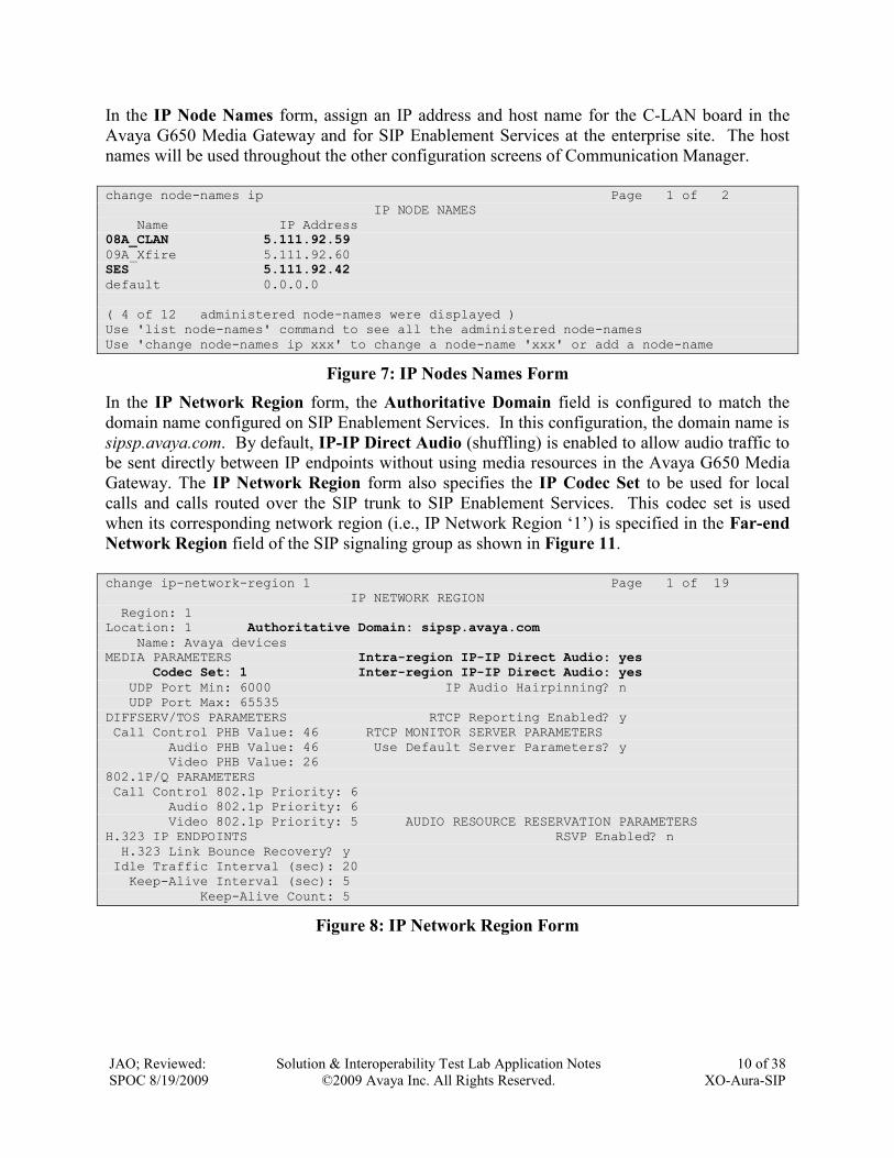
In the IP Node Names form, assign an IP address and host name for the C-LAN board in the
Avaya G650 Media Gateway and for SIP Enablement Services at the enterprise site. The host
names will be used throughout the other configuration screens of Communication Manager.
change node-names ip Page 1 of 2
IP NODE NAMES
Name IP Address
08A_CLAN 5.111.92.59
09A_Xfire 5.111.92.60
SES 5.111.92.42
default 0.0.0.0
( 4 of 12 administered node-names were displayed )
Use 'list node-names' command to see all the administered node-names
Use 'change node-names ip xxx' to change a node-name 'xxx' or add a node-name
Figure 7: IP Nodes Names Form
In the IP Network Region form, the Authoritative Domain field is configured to match the
domain name configured on SIP Enablement Services. In this configuration, the domain name is
sipsp.avaya.com. By default, IP-IP Direct Audio (shuffling) is enabled to allow audio traffic to
be sent directly between IP endpoints without using media resources in the Avaya G650 Media
Gateway. The IP Network Region form also specifies the IP Codec Set to be used for local
calls and calls routed over the SIP trunk to SIP Enablement Services. This codec set is used
when its corresponding network region (i.e., IP Network Region „1‟) is specified in the Far-end
Network Region field of the SIP signaling group as shown in Figure 11.
change ip-network-region 1 Page 1 of 19
IP NETWORK REGION
Region: 1
Location: 1 Authoritative Domain: sipsp.avaya.com
Name: Avaya devices
MEDIA PARAMETERS Intra-region IP-IP Direct Audio: yes
Codec Set: 1 Inter-region IP-IP Direct Audio: yes
UDP Port Min: 6000 IP Audio Hairpinning? n
UDP Port Max: 65535
DIFFSERV/TOS PARAMETERS RTCP Reporting Enabled? y
Call Control PHB Value: 46 RTCP MONITOR SERVER PARAMETERS
Audio PHB Value: 46 Use Default Server Parameters? y
Video PHB Value: 26
802.1P/Q PARAMETERS
Call Control 802.1p Priority: 6
Audio 802.1p Priority: 6
Video 802.1p Priority: 5 AUDIO RESOURCE RESERVATION PARAMETERS
H.323 IP ENDPOINTS RSVP Enabled? n
H.323 Link Bounce Recovery? y
Idle Traffic Interval (sec): 20
Keep-Alive Interval (sec): 5
Keep-Alive Count: 5
Figure 8: IP Network Region Form

JAO; Reviewed:
SPOC 8/19/2009
Solution & Interoperability Test Lab Application Notes
©2009 Avaya Inc. All Rights Reserved.
11 of 38
XO-Aura-SIP
In the IP Codec Set form, select the audio codec type supported for calls routed over the SIP
trunk. The form is accessed via the change ip-codec-set 1 command. Note that codec set „1‟
was specified in IP Network Region „1‟ shown in Figure 8. The XO SIP trunking service
supports G.711 mu-law and G.729A codecs, which were included in the IP Codec Set form. In
the configuration below, G.729A is the preferred codec.
change ip-codec-set 1 Page 1 of 2
IP Codec Set
Codec Set: 1
Audio Silence Frames Packet
Codec Suppression Per Pkt Size(ms)
1: G.729A n 2 20
2: G.711MU n 2 20
3:
4:
5:
6:
7:
Figure 9: IP Codec Set – Page 1
To enable Fax T.38, set the Fax mode on Page 2 of the IP Codec Set form to t.38-standard.
change ip-codec-set 1 Page 2 of 2
IP Codec Set
Allow Direct-IP Multimedia? n
Mode Redundancy
FAX t.38-standard 0
Modem off 0
TDD/TTY off 3
Clear-channel n 0
Figure 10: IP Codec Set – Page 2

JAO; Reviewed:
SPOC 8/19/2009
Solution & Interoperability Test Lab Application Notes
©2009 Avaya Inc. All Rights Reserved.
12 of 38
XO-Aura-SIP
Prior to configuring a SIP trunk group for communication with SIP Enablement Services, a SIP
signaling group must be configured. This signaling group is used for outgoing calls to the PSTN.
Configure the Signaling Group form shown in Figure 11 as follows:
Set the Group Type field to sip.
The Transport Method field will default to tls (Transport Layer Security).
Specify the C-LAN board in the G650 Media Gateway and the SIP Enablement Services
Server as the two ends of the signaling group in the Near-end Node Name field and the
Far-end Node Name field, respectively. These field values are taken from the IP Node
Names form shown in Figure 7.
Ensure that the recommended TLS port value of 5061 is configured in the Near-end
Listen Port and the Far-end Listen Port fields.
The preferred codec for the call will be selected from the IP codec set assigned to the IP
network region specified in the Far-end Network Region field. Although the same
network region (Network Region 1) was used for local and PSTN calls in this
configuration, a different network region for PSTN calls could have been specified.
Enter the domain name of SIP Enablement Services in the Far-end Domain field. In this
configuration, the domain name is sipsp.avaya.com. This domain is specified in the
Uniform Resource Identifier (URI) of the “SIP To Address” in the INVITE message.
Mis-configuring this field may prevent calls from being successfully established to other
SIP endpoints or to the PSTN.
If calls to/from SIP endpoints are to be shuffled, then the Direct IP-IP Audio
Connections field must be set to „y‟.
The DTMF over IP field should be set to the default value of rtp-payload.
Communication Manager supports DTMF transmission using RFC 2833. The default
values for the other fields may be used.
add signaling-group 1 Page 1 of 1
SIGNALING GROUP
Group Number: 1 Group Type: sip
Transport Method: tls
IMS Enabled? n
Near-end Node Name: 08A_CLAN Far-end Node Name: SES
Near-end Listen Port: 5061 Far-end Listen Port: 5061
Far-end Network Region: 1
Far-end Domain: sipsp.avaya.com
Bypass If IP Threshold Exceeded? n
DTMF over IP: rtp-payload Direct IP-IP Audio Connections? y
Session Establishment Timer(min): 3 IP Audio Hairpinning? n
Enable Layer 3 Test? n Direct IP-IP Early Media? n
H.323 Station Outgoing Direct Media? n Alternate Route Timer(sec): 6
Figure 11: Signaling Group for Outgoing Calls to PSTN

JAO; Reviewed:
SPOC 8/19/2009
Solution & Interoperability Test Lab Application Notes
©2009 Avaya Inc. All Rights Reserved.
13 of 38
XO-Aura-SIP
The following signaling group is used for incoming calls from the PSTN. A different signaling
group is required because XO specifies a different domain in the FROM header of the SIP
INVITE message than what was configured in the far-end domain name field of the signaling
group shown in Figure 11. The Far-end Domain field was left blank, which would match any
domain sent by XO. In the test configuration, the IP address of the Sonus Networks NBS was
sent as the domain for calls originated from the PSTN. Configuring that IP address in the Far-
end Domain field is also supported. Follow the instructions described for the signaling group
configured in Figure 11 for the other fields.
add signaling-group 2 Page 1 of 1
SIGNALING GROUP
Group Number: 2 Group Type: sip
Transport Method: tls
IMS Enabled? n
Near-end Node Name: 08A_CLAN Far-end Node Name: SES
Near-end Listen Port: 5061 Far-end Listen Port: 5061
Far-end Network Region: 1
Far-end Domain:
Bypass If IP Threshold Exceeded? n
DTMF over IP: rtp-payload Direct IP-IP Audio Connections? y
Session Establishment Timer(min): 3 IP Audio Hairpinning? n
Enable Layer 3 Test? n Direct IP-IP Early Media? n
H.323 Station Outgoing Direct Media? n Alternate Route Timer(sec): 6
Figure 12: Signaling Group for Incoming Calls from PSTN

JAO; Reviewed:
SPOC 8/19/2009
Solution & Interoperability Test Lab Application Notes
©2009 Avaya Inc. All Rights Reserved.
14 of 38
XO-Aura-SIP
Configure the Trunk Group form as shown in Figure 13. This trunk group is used for outgoing
calls to the PSTN. Set the Group Type field to sip, set the Service Type field to public-ntwrk,
specify the signaling group associated with this trunk group in the Signaling Group field, and
specify the Number of Members supported by this SIP trunk group. For a call between the
PSTN and a SIP endpoint, two trunk members are used for the duration of the call. For a call
between the PSTN and a non-SIP endpoint, one trunk member is used for the duration of the call.
Configure the other fields in bold and accept the default values for the remaining fields.
add trunk-group 1 Page 1 of 21
TRUNK GROUP
Group Number: 1 Group Type: sip CDR Reports: y
Group Name: Calls to SIP/PSTN COR: 1 TN: 1 TAC: 1001
Direction: two-way Outgoing Display? n
Dial Access? n Night Service:
Queue Length: 0
Service Type: public-ntwrk Auth Code? n
Signaling Group: 1
Number of Members: 30
Figure 13: Trunk Group for Outgoing Calls to PSTN – Page 1
On Page 3 of the trunk group form, set the Numbering Format field to public. This field
specifies the format of the calling party number sent to the far-end.
add trunk-group 1 Page 3 of 21
TRUNK FEATURES
ACA Assignment? n Measured: none
Maintenance Tests? y
Numbering Format: public
UUI Treatment: service-provider
Replace Restricted Numbers? n
Replace Unavailable Numbers? n
Show ANSWERED BY on Display? y
Figure 14: Trunk Group for Outgoing Calls to PSTN – Page 3
On Page 4 of the trunk group form, enable Send Diversion Header. This is required to support
incoming PSTN calls that are forwarded to a PSTN phone or redirected to an EC500 phone.
add trunk-group 1 Page 4 of 21
PROTOCOL VARIATIONS
Mark Users as Phone? n
Prepend '+' to Calling Number? n
Send Transferring Party Information? n
Network Call Redirection? n
Send Diversion Header? y
Support Request History? y
Telephone Event Payload Type:
Figure 15: Trunk Group for Outgoing calls to PSTN – Page 4

JAO; Reviewed:
SPOC 8/19/2009
Solution & Interoperability Test Lab Application Notes
©2009 Avaya Inc. All Rights Reserved.
15 of 38
XO-Aura-SIP
Repeat the trunk group configuration in Figure 13 and Figure 14 for the trunk group used for
incoming calls from the PSTN. The only difference would be to specify the signaling group
configured in Figure 12 for this trunk group. All other fields may be entered as shown.
Note: To call an endpoint on the Avaya SIP-based network from the PSTN, a 10-digit DID
number is dialed. This 10-digit dialed number is received by Communication Manager and
converted to the appropriate 5-digit extension in the Incoming Call Handling Treatment Table
(not shown) for trunk group „2‟.
add trunk-group 2 Page 1 of 21
TRUNK GROUP
Group Number: 2 Group Type: sip CDR Reports: y
Group Name: Calls from PSTN COR: 1 TN: 1 TAC: 1002
Direction: two-way Outgoing Display? n
Dial Access? n Night Service:
Queue Length: 0
Service Type: public-ntwrk Auth Code? n
Signaling Group: 2
Number of Members: 10
Figure 16: Trunk Group for Incoming Calls from PSTN
Configure the Public/Unknown Numbering Format form to send the calling party number to
the far-end. Add an entry so that local stations with a 5-digit extension beginning with „2‟ and
whose calls are routed over SIP trunk group „1‟ have the number sent to the far-end for display
purposes. In the example shown in Figure 17, a CPN prefix is added to the 5-digit extension so
that a 10-digit calling party number (e.g., extension 20003 is converted to 2146320003) is sent to
the far-end.
Note: The 10-digit CPN must be recognized by the XO VoIP network or the call will be denied.
change public-unknown-numbering 0 Page 1 of 2
NUMBERING - PUBLIC/UNKNOWN FORMAT
Total
Ext Ext Trk CPN CPN
Len Code Grp(s) Prefix Len
Total Administered: 1
5 2 1 21463 10 Maximum Entries: 9999
Figure 17: Public Unknown Format Form

JAO; Reviewed:
SPOC 8/19/2009
Solution & Interoperability Test Lab Application Notes
©2009 Avaya Inc. All Rights Reserved.
16 of 38
XO-Aura-SIP
The first step in configuring an off-PBX station (OPS) for the Avaya SIP telephones registered
with SIP Enablement Services is to add a station with the appropriate station Type as shown in
Figure 18. A descriptive Name may also be provided. The Class of Restriction (COR) and
Class of Service (COS) assigned to the station should be configured with the appropriate call
restrictions. Repeat this step for each SIP endpoint at the enterprise site.
add station 20003 Page 1 of 6
STATION
Extension: 20003 Lock Messages? n BCC: 0
Type: 9600SIP Security Code: TN: 1
Port: IP Coverage Path 1: COR: 1
Name: Johnny SIP Coverage Path 2: COS: 1
Hunt-to Station:
STATION OPTIONS
Time of Day Lock Table:
Loss Group: 19 Personalized Ringing Pattern: 1
Message Lamp Ext: 20003
Speakerphone: 2-way Mute Button Enabled? y
Display Language: english Expansion Module? n
Survivable GK Node Name:
Survivable COR: internal Media Complex Ext:
Survivable Trunk Dest? y IP SoftPhone? n
Customizable Labels? y
Figure 18: SIP Station – Page 1
On Page 2 of the Station form, verify that the Per Station CPN – Send Calling Number field is
set to „y‟ or blank to allow calling party number information to be sent to the far-end when
placing outgoing calls from this station. The default value for this field is blank.
add station 20003 Page 2 of 6
STATION
FEATURE OPTIONS
LWC Reception: spe Auto Select Any Idle Appearance? n
LWC Activation? y Coverage Msg Retrieval? y
LWC Log External Calls? n Auto Answer: none
CDR Privacy? n Data Restriction? n
Redirect Notification? y Idle Appearance Preference? n
Per Button Ring Control? n Bridged Idle Line Preference? n
Bridged Call Alerting? n Restrict Last Appearance? y
Active Station Ringing: single
EMU Login Allowed? n
H.320 Conversion? n Per Station CPN - Send Calling Number?
Service Link Mode: as-needed EC500 State: disabled
Multimedia Mode: enhanced
MWI Served User Type: Display Client Redirection? n
AUDIX Name: Select Last Used Appearance? n
Coverage After Forwarding? s
Direct IP-IP Audio Connections? y
Emergency Location Ext: 20003 Always Use? n IP Audio Hairpinning? n
Figure 19: SIP Station – Page 2

JAO; Reviewed:
SPOC 8/19/2009
Solution & Interoperability Test Lab Application Notes
©2009 Avaya Inc. All Rights Reserved.
17 of 38
XO-Aura-SIP
On Page 4 of the Station form, configure the appropriate number of call appearances for the SIP
telephone. For example, the Avaya 9630 SIP Telephone was configured to support three call
appearances as shown in Figure 20.
add station 20003 Page 4 of 6
STATION
SITE DATA
Room: Headset? n
Jack: Speaker? n
Cable: Mounting: d
Floor: Cord Length: 0
Building: Set Color:
ABBREVIATED DIALING
List1: List2: List3:
BUTTON ASSIGNMENTS
1: call-appr 5:
2: call-appr 6:
3: call-appr 7:
4: 8:
Figure 20: SIP Station – Page 4
The second step of configuring an off-PBX station is to configure the Stations with Off-PBX
Telephone Integration form so that calls destined for a SIP telephone at the enterprise site are
routed to SIP Enablement Services, which will then terminate the call to the SIP telephone. On
this form, specify the extension of the SIP endpoint and set the Application field to OPS. The
Phone Number field is set to the digits to be sent over the SIP trunk. In this case, the SIP
telephone extensions configured on SIP Enablement Services also match the extensions of the
corresponding stations on Communication Manager. However, this is not a requirement.
Finally, the Trunk Selection field is set to „1‟, the SIP trunk group number. This field specifies
the trunk group used to route the outgoing call. Another option for routing a call over a SIP
trunk group is to use Auto Alternate Routing (AAR) or Auto Route Selection (ARS) routing
instead. In this case, the Trunk Selection field would be set to aar or ars. Configuration of
other AAR or ARS forms would also be required. Refer to [1] for information on routing calls
using AAR or ARS. Repeat this step for each SIP endpoint at the enterprise site.
change off-pbx-telephone station-mapping 20003 Page 1 of 3
STATIONS WITH OFF-PBX TELEPHONE INTEGRATION
Station Application Dial CC Phone Number Trunk Config Dual
Extension Prefix Selection Set Mode
20003 OPS - 20003 1 1
Figure 21: Stations with Off-PBX Telephone Integration – Page 1

JAO; Reviewed:
SPOC 8/19/2009
Solution & Interoperability Test Lab Application Notes
©2009 Avaya Inc. All Rights Reserved.
18 of 38
XO-Aura-SIP
On Page 2, set the Call Limit field to the maximum number of calls that may be active
simultaneously at the station. In this example, the call limit is set to „3‟, which corresponds to
the number of call appearances configured on the station form. Accept the default values for the
other fields.
change off-pbx-telephone station-mapping 20003 Page 2 of 3
STATIONS WITH OFF-PBX TELEPHONE INTEGRATION
Station Appl Call Mapping Calls Bridged Location
Extension Name Limit Mode Allowed Calls
20003 OPS 3 both all none 1
Figure 22: Stations with Off-PBX Telephone Integration – Page 2
Most of the field values in Off-PBX Telephone Configuration Set form are left at their default
values. However, the Cellular Voice Mail Detection field may have to be decreased. For
example, if an EC500 call that is routed over the PSTN is answered too quickly, the call may be
dropped. In this case, the aforementioned field would have to be decreased from the default
value of „4‟ to a lower value, such as „1‟ or „2‟, depending on the network configuration. In this
example, the field was set to „2‟.
change off-pbx-telephone configuration-set 1 Page 1 of 1
CONFIGURATION SET: 1
Configuration Set Description:
Calling Number Style: network
CDR for Origination: phone-number
CDR for Calls to EC500 Destination? y
Fast Connect on Origination? n
Post Connect Dialing Options: dtmf
Cellular Voice Mail Detection: timed (seconds): 2
Barge-in Tone? n
Calling Number Verification? y
Call Appearance Selection for Origination: primary-first
Confirmed Answer? n
Use Shared Voice Connections for Second Call Answered? n
Use Shared Voice Connections for Second Call Initiated? n
Figure 23: Off-PBX Telephone Configuration Set

JAO; Reviewed:
SPOC 8/19/2009
Solution & Interoperability Test Lab Application Notes
©2009 Avaya Inc. All Rights Reserved.
19 of 38
XO-Aura-SIP
5. Configure Avaya AuraTM
SIP Enablement Services This section covers the administration of Avaya Aura
TM SIP Enablement Services. SIP
Enablement Services is configured via an Internet browser using the Administration web
interface. To access the Administration web interface, enter http://<ip-addr>/admin as the URL
in an Internet browser, where <ip-addr> is the IP address of SIP Enablement Services. Log in
with the appropriate credentials and then select the Launch SES Administration Interface link in
the next screen. The main screen shown in Figure 24 is displayed.
Figure 24: Main Screen

JAO; Reviewed:
SPOC 8/19/2009
Solution & Interoperability Test Lab Application Notes
©2009 Avaya Inc. All Rights Reserved.
20 of 38
XO-Aura-SIP
From the left pane of the Administration web interface, expand the Server Configuration option
and select System Properties. In the System Properties screen, enter the domain name
assigned to the Avaya SIP-based network and the SIP License Host. For the SIP License Host
field, enter the fully qualified domain name or the IP address of the SES server that is running
the WebLM application and has the associated license file installed. This entry should always
correspond to the localhost unless the WebLM server is not co-resident with this server. After
configuring the System Properties screen, click the Update button.
Figure 25: System Properties

JAO; Reviewed:
SPOC 8/19/2009
Solution & Interoperability Test Lab Application Notes
©2009 Avaya Inc. All Rights Reserved.
21 of 38
XO-Aura-SIP
After setting up the domain in the System Properties screen, create a host entry for SIP
Enablement Services. The following example shows the Edit Host screen since the host had
already been configured. Enter the IP address of SIP Enablement Services in the Host IP
Address field. The Profile Service Password was specified during the system installation.
Next, configure the Host Type field. In this example, the host server was configured as an SES
combined home-edge. The default values for the other fields may be used as shown in Figure
26. Click the Update button.
Figure 26: Host

JAO; Reviewed:
SPOC 8/19/2009
Solution & Interoperability Test Lab Application Notes
©2009 Avaya Inc. All Rights Reserved.
22 of 38
XO-Aura-SIP
Under the Communication Manager Servers option in the Administration web interface, select
Add to add the Avaya S8720 Servers in the enterprise site since a SIP trunk is required between
Communication Manager and SIP Enablement Services. In the Add Communication Manager
Interface screen shown in Figure 26, enter the following information:
A descriptive name in the Communication Manager Server Interface Name field (e.g.,
SIPCLAN08A).
Select the home server in the Host field.
Select TLS (Transport Link Security) for the SIP Trunk Link Type. TLS provides
encryption at the transport layer.
Enter the IP address of the C-LAN board in the Avaya G650 Media gateway in the SIP
Trunk IP Address field.
After completing the Add Communication Manager Server Interface screen, click the Add
button. Refer to [3] for additional information on configuring the remaining fields.
Figure 27: Add Communication Manager Server Interface

JAO; Reviewed:
SPOC 8/19/2009
Solution & Interoperability Test Lab Application Notes
©2009 Avaya Inc. All Rights Reserved.
23 of 38
XO-Aura-SIP
Incoming calls originating from the PSTN and arriving at SIP Enablement Services are routed to
Communication Manager for termination services. Calls to be routed to Communication
Manager are specified in a Communication Manager Server Address Map. The Uniform
Resource Identifier (URI) of an incoming INVITE message is compared to the pattern
configured in the address map, and if there is a match, the call is routed to Communication
Manager. The URI usually takes the form of sip:user@domain, where domain can be a
domain name or an IP address. In this example, user is actually the telephone number of the
phone. An example of a URI would be sip:[email protected]. Only incoming
calls from the PSTN require a Communication Manager address map. By default, all calls
originated from an Avaya SIP telephone are routed through Communication Manager for
origination services because the Avaya SIP telephones are assigned a media server extension.
To configure a Communication Manager Server Address Map, select Communication
Manager Servers in the left pane of the Administration web interface. This will display the List
Communication Manager Servers screen. Click on the Map link associated with the
appropriate server to display the List Communication Manager Server Address Map screen
and click on the Add Map In New Group link. The screen shown in Figure 28 is displayed.
Provide a descriptive name in the Name field and enter the regular expression to be used for the
pattern matching in the Pattern field. In this configuration, the pattern specification matches a
URI that begins with sip:214 followed by seven digits. Note that DID numbers beginning
with area code 214 were assigned to endpoints at the enterprise site. See Appendix B for a more
detailed description of the syntax for address map patterns. Click the Add button. Repeat this
procedure to add an address map for routing incoming toll-free calls, if necessary.
Figure 28: Communication Manager Server Address Map

JAO; Reviewed:
SPOC 8/19/2009
Solution & Interoperability Test Lab Application Notes
©2009 Avaya Inc. All Rights Reserved.
24 of 38
XO-Aura-SIP
After the Communication Manager Server Address Map is added, the first Communication
Manager Server Contact is created automatically. For the address map added in Figure 28, the
following contact was created: sip:$(user)@5.111.92.59:5061;transport=tls
The contact specifies the IP address of the C-LAN board in the Avaya G650 Media Gateway and
the transport protocol used to send SIP signaling messages. The user in the original request URI
is substituted for $(user).
After configuring the media server address map, the List Communication Manager Server
Address Map screen appears as shown in Figure 29.
Figure 29: List Communication Manager Server Address Map
JAO; Reviewed:
SPOC 8/19/2009
Solution & Interoperability Test Lab Application Notes
©2009 Avaya Inc. All Rights Reserved.
25 of 38
XO-Aura-SIP
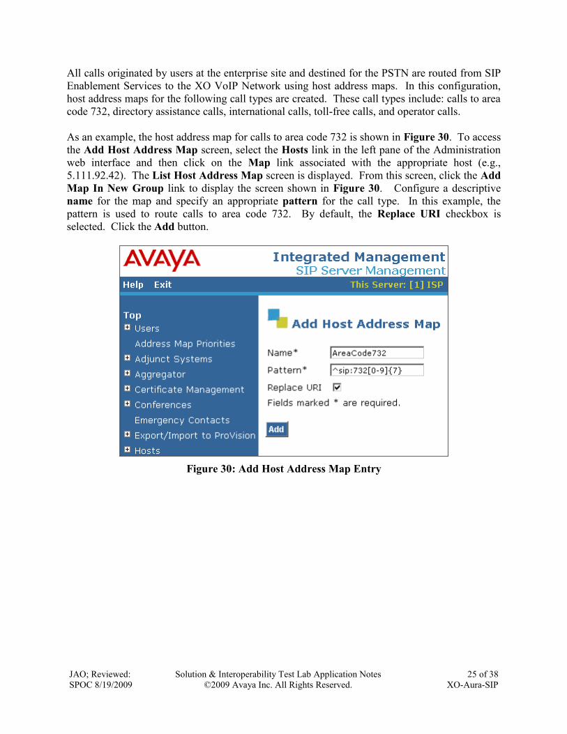
All calls originated by users at the enterprise site and destined for the PSTN are routed from SIP
Enablement Services to the XO VoIP Network using host address maps. In this configuration,
host address maps for the following call types are created. These call types include: calls to area
code 732, directory assistance calls, international calls, toll-free calls, and operator calls.
As an example, the host address map for calls to area code 732 is shown in Figure 30. To access
the Add Host Address Map screen, select the Hosts link in the left pane of the Administration
web interface and then click on the Map link associated with the appropriate host (e.g.,
5.111.92.42). The List Host Address Map screen is displayed. From this screen, click the Add
Map In New Group link to display the screen shown in Figure 30. Configure a descriptive
name for the map and specify an appropriate pattern for the call type. In this example, the
pattern is used to route calls to area code 732. By default, the Replace URI checkbox is
selected. Click the Add button.
Figure 30: Add Host Address Map Entry

JAO; Reviewed:
SPOC 8/19/2009
Solution & Interoperability Test Lab Application Notes
©2009 Avaya Inc. All Rights Reserved.
26 of 38
XO-Aura-SIP
From the List Host Address Map, click on the Add Another Contact link associated with the
address map added in Figure 30. In this screen, the Contact field specifies the destination for
the call and it is configured as:
sip:$(user)@20.58.163.138:5060;transport=udp
The contact specifies the IP address of the Sonus Networks NBS in the XO VoIP Network and
the transport protocol used to send SIP signaling messages. The transport protocol must be
coordinated with XO. The user in the original request URI is substituted for $(user). Click
the Add button when completed.
Figure 31: Add Host Contact
Repeat the above procedure to add an address map for directory assistance, international,
operator, and toll-free calls.

JAO; Reviewed:
SPOC 8/19/2009
Solution & Interoperability Test Lab Application Notes
©2009 Avaya Inc. All Rights Reserved.
27 of 38
XO-Aura-SIP
After configuring the host address maps, the List Host Address Map screen appears as shown in
Figure 32.
Figure 32: List Host Address Map

JAO; Reviewed:
SPOC 8/19/2009
Solution & Interoperability Test Lab Application Notes
©2009 Avaya Inc. All Rights Reserved.
28 of 38
XO-Aura-SIP
Add a user for each Avaya SIP telephone registering with SIP Enablement Services. In the Add
User screen, enter the extension of the SIP endpoint in the Primary Handle field. Enter a user
password in the Password and Confirm Password fields. In the Host field, select the SIP
Enablement Services server hosting the domain (sipsp.avaya.com) for this user. Enter the First
Name and Last Name of the user. To associate a Communication Manager server extension
with this user, select the Add Communication Manager Extension checkbox. Calls from this
user will always be routed through Communication Manager over the SIP trunk for origination
services. The Add Communication Manager Extension screen shown in Figure 34 will be
displayed after adding this user profile by clicking on the Add button.
Figure 33: Add User
JAO; Reviewed:
SPOC 8/19/2009
Solution & Interoperability Test Lab Application Notes
©2009 Avaya Inc. All Rights Reserved.
29 of 38
XO-Aura-SIP
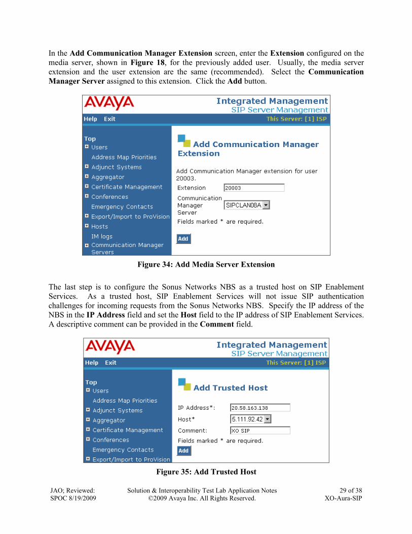
In the Add Communication Manager Extension screen, enter the Extension configured on the
media server, shown in Figure 18, for the previously added user. Usually, the media server
extension and the user extension are the same (recommended). Select the Communication
Manager Server assigned to this extension. Click the Add button.
Figure 34: Add Media Server Extension
The last step is to configure the Sonus Networks NBS as a trusted host on SIP Enablement
Services. As a trusted host, SIP Enablement Services will not issue SIP authentication
challenges for incoming requests from the Sonus Networks NBS. Specify the IP address of the
NBS in the IP Address field and set the Host field to the IP address of SIP Enablement Services.
A descriptive comment can be provided in the Comment field.
Figure 35: Add Trusted Host

JAO; Reviewed:
SPOC 8/19/2009
Solution & Interoperability Test Lab Application Notes
©2009 Avaya Inc. All Rights Reserved.
30 of 38
XO-Aura-SIP
6. XO VoIP Network Configuration To use the XO SIP service, a customer must order the service from XO using their sales
processes. The process can be started by contacting XO via their corporate website at
http://www.xo.com or by contacting a XO sales representative.
The following table contains the configuration information, coordinated with XO, which was
used during the interoperability compliance testing to verify the XO SIP service.
Feature Test Configuration
Specify Codec(s) Required:
G.711mu-law
G.729A
RFC2833 DTMF (required)
The network configuration described in these Application
Notes was tested with the codecs (payload types) listed in
the left column.
Define Dial Plan 10-digit dialing, directory assistance, toll-free,
international, operator, and collect calls were supported by
the test configuration.
Listed Directory Numbers
provided by XO
Listed directory numbers should be assigned to the
endpoints at the enterprise site. This allows calls to be
delivered from the PSTN. In this configuration, listed
directory numbers beginning with area code 214 were
assigned to the SIP, H.323, digital, and analog endpoints
in the enterprise network. In addition, these DID numbers
will be sent as the CPN to the XO VoIP network for
authentication.
XO provides Proxy IP Address The IP address of the Sonus Networks NBS in the XO
VoIP network was 20.58.163.138 and used to configure
the host address maps in SIP Enablement Services.
Customer provides IP Address of
Avaya AuraTM
SIP Enablement
Services
The IP address of SIP Enablement Services in the
enterprise network was 5.111.92.42. XO used this IP
address for routing calls destined to the listed directory
numbers assigned to the enterprise site.
SIP Transport Protocol and Port SIP signaling was transported between SIP Enablement
Services and XO using UDP and port 5060.

JAO; Reviewed:
SPOC 8/19/2009
Solution & Interoperability Test Lab Application Notes
©2009 Avaya Inc. All Rights Reserved.
31 of 38
XO-Aura-SIP
7. General Test Approach and Test Results This section describes the interoperability compliance testing used to verify SIP trunking
interoperability between the XO VoIP network and an Avaya SIP-based network. This section
covers the general test approach and the test results.
An enterprise site containing an Avaya SIP-based network was interconnected to the XO VoIP
network using SIP trunking. The SIP trunk was established between Avaya AuraTM
SIP
Enablement Services and a Sonus Networks NBS. This allowed the enterprise site to access the
PSTN through the XO VoIP network. The features and functionality listed in Section 1.1 were
covered during the SIP trunking interoperability compliance test.
All test cases passed, with the following observations noted.
An incoming PSTN call to the Avaya network that is supervised transferred to a PSTN
station requires that the Telephone Event Payload Type field in the SIP trunk group
form be set to the same value used by the XO SIP trunking service. During the testing,
XO used payload type „101‟. By default, Communication Manager uses payload type
„127‟. This behavior was not observed if the original call was initiated by an internal
Avaya station or for blind transfers.
An incoming PSTN call to an H.323 station with the EC500 feature enabled rings the
desk phone and the EC500 phone simultaneously. If the desk phone answers the call, it
can extend the call to the EC500 phone successfully. However, when the desk phone
hangs up, the call between the PSTN phone and the EC500 phone also drops. This issue
was not observed if the original call was initiated by an internal Avaya station or when
the desk phone was a digital station.

JAO; Reviewed:
SPOC 8/19/2009
Solution & Interoperability Test Lab Application Notes
©2009 Avaya Inc. All Rights Reserved.
32 of 38
XO-Aura-SIP
8. Verification Steps This section provides verification steps that may be performed in the field to verify that
incoming and outgoing PSTN calls can be established between the Avaya IP network and the
XO VoIP network.
1. Verify that endpoints at the enterprise site can place calls to the PSTN and that the call can
remain active for more than 35 seconds. This time period is included to verify that proper
routing of the SIP messaging has satisfied SIP protocol timers.
2. Verify that endpoints at the enterprise site can receive calls from the PSTN and that the call
can remain active for more than 35 seconds.
3. Verify that the user on the PSTN can terminate an active call by hanging up.
4. Verify that an endpoint at the enterprise site can terminate an active call by hanging up.
5. If Shuffling is enabled, verify that a call originating or terminating on an Avaya IP telephone
is shuffled. To determine if the call is shuffled, identify the trunk member active on the call
by running the status trunk <group> command on the SAT of Communication Manager.
Next, run the status trunk group/member command and check the Audio Connection
field. If the call is shuffled, the field should be set to ip-direct; otherwise, the field would be
set to ip-tdm.
9. Conclusion These Application Notes describe the configuration steps required to connect an enterprise site
consisting of an Avaya SIP-based Network to the XO VoIP Network. This allows enterprise
customers to reduce long distance and interconnection costs by accessing the PSTN through the
XO VoIP Network. Enterprise customers subscribing to the XO SIP Trunking service can
receive and place local, long distance, international, directory assistance, operator, and toll-free
calls.
10. References This section references the Avaya documentation relevant to these Application Notes. The
following Avaya product documentation is available at http://support.avaya.com.
[1] Administering Avaya AuraTM
Communication Manager, May 2009, Issue 5, Document
Number 03-300509.
[2] SIP Support in Avaya AuraTM
Communication Manager Running on the Avaya S8xxx
Servers, May 2009, Issue 9, Document Number 555-245-206.
[3] Installing, Administering, Maintaining, and Upgrading Avaya AuraTM
SIP Enablement
Services, May 2009, Issue 7, Document Number 03-600768.
Additional information about the XO Enterprise IP Trunking service is available at
http://www.xo.com.
JAO; Reviewed:
SPOC 8/19/2009
Solution & Interoperability Test Lab Application Notes
©2009 Avaya Inc. All Rights Reserved.
33 of 38
XO-Aura-SIP
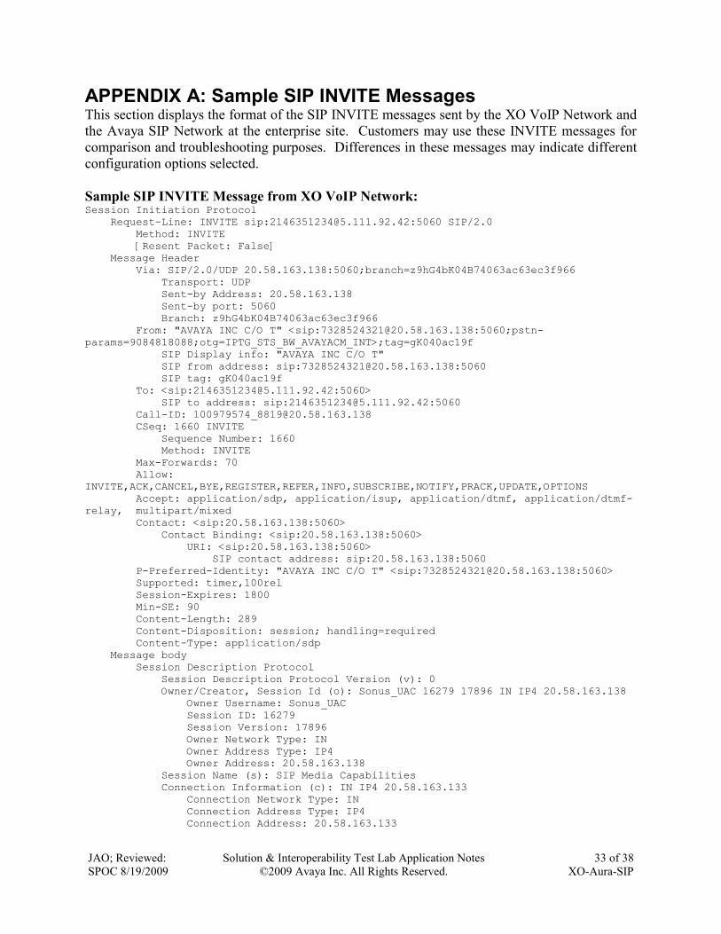
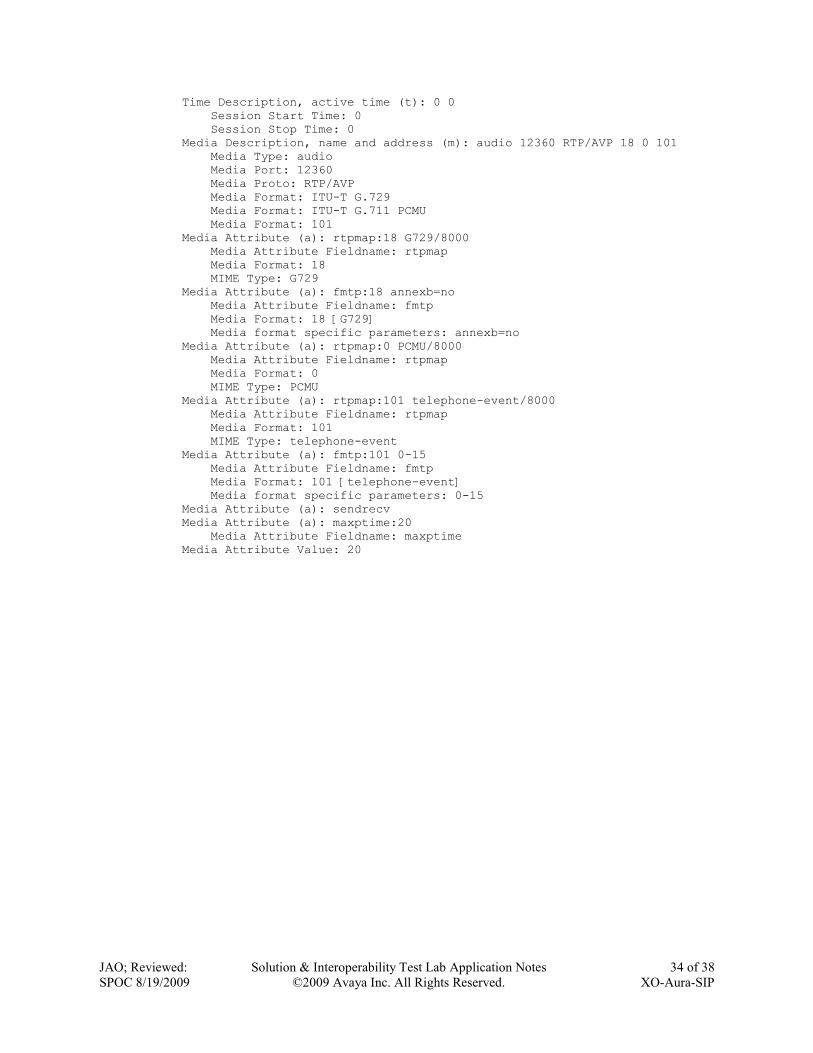
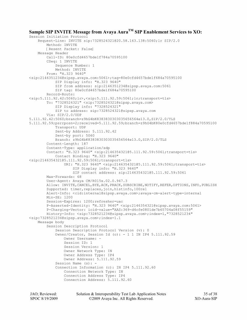
APPENDIX A: Sample SIP INVITE Messages This section displays the format of the SIP INVITE messages sent by the XO VoIP Network and
the Avaya SIP Network at the enterprise site. Customers may use these INVITE messages for
comparison and troubleshooting purposes. Differences in these messages may indicate different
configuration options selected.
Sample SIP INVITE Message from XO VoIP Network: Session Initiation Protocol
Request-Line: INVITE sip:[email protected]:5060 SIP/2.0
Method: INVITE
[Resent Packet: False]
Message Header
Via: SIP/2.0/UDP 20.58.163.138:5060;branch=z9hG4bK04B74063ac63ec3f966
Transport: UDP
Sent-by Address: 20.58.163.138
Sent-by port: 5060
Branch: z9hG4bK04B74063ac63ec3f966
From: "AVAYA INC C/O T" <sip:[email protected]:5060;pstn-
params=9084818088;otg=IPTG_STS_BW_AVAYACM_INT>;tag=gK040ac19f
SIP Display info: "AVAYA INC C/O T"
SIP from address: sip:[email protected]:5060
SIP tag: gK040ac19f
To: <sip:[email protected]:5060>
SIP to address: sip:[email protected]:5060
Call-ID: [email protected]
CSeq: 1660 INVITE
Sequence Number: 1660
Method: INVITE
Max-Forwards: 70
Allow:
INVITE,ACK,CANCEL,BYE,REGISTER,REFER,INFO,SUBSCRIBE,NOTIFY,PRACK,UPDATE,OPTIONS
Accept: application/sdp, application/isup, application/dtmf, application/dtmf-
relay, multipart/mixed
Contact: <sip:20.58.163.138:5060>
Contact Binding: <sip:20.58.163.138:5060>
URI: <sip:20.58.163.138:5060>
SIP contact address: sip:20.58.163.138:5060
P-Preferred-Identity: "AVAYA INC C/O T" <sip:[email protected]:5060>
Supported: timer,100rel
Session-Expires: 1800
Min-SE: 90
Content-Length: 289
Content-Disposition: session; handling=required
Content-Type: application/sdp
Message body
Session Description Protocol
Session Description Protocol Version (v): 0
Owner/Creator, Session Id (o): Sonus_UAC 16279 17896 IN IP4 20.58.163.138
Owner Username: Sonus_UAC
Session ID: 16279
Session Version: 17896
Owner Network Type: IN
Owner Address Type: IP4
Owner Address: 20.58.163.138
Session Name (s): SIP Media Capabilities
Connection Information (c): IN IP4 20.58.163.133
Connection Network Type: IN
Connection Address Type: IP4
Connection Address: 20.58.163.133
JAO; Reviewed:
SPOC 8/19/2009
Solution & Interoperability Test Lab Application Notes
©2009 Avaya Inc. All Rights Reserved.
34 of 38
XO-Aura-SIP
Time Description, active time (t): 0 0
Session Start Time: 0
Session Stop Time: 0
Media Description, name and address (m): audio 12360 RTP/AVP 18 0 101
Media Type: audio
Media Port: 12360
Media Proto: RTP/AVP
Media Format: ITU-T G.729
Media Format: ITU-T G.711 PCMU
Media Format: 101
Media Attribute (a): rtpmap:18 G729/8000
Media Attribute Fieldname: rtpmap
Media Format: 18
MIME Type: G729
Media Attribute (a): fmtp:18 annexb=no
Media Attribute Fieldname: fmtp
Media Format: 18 [G729]
Media format specific parameters: annexb=no
Media Attribute (a): rtpmap:0 PCMU/8000
Media Attribute Fieldname: rtpmap
Media Format: 0
MIME Type: PCMU
Media Attribute (a): rtpmap:101 telephone-event/8000
Media Attribute Fieldname: rtpmap
Media Format: 101
MIME Type: telephone-event
Media Attribute (a): fmtp:101 0-15
Media Attribute Fieldname: fmtp
Media Format: 101 [telephone-event]
Media format specific parameters: 0-15
Media Attribute (a): sendrecv
Media Attribute (a): maxptime:20
Media Attribute Fieldname: maxptime
Media Attribute Value: 20
JAO; Reviewed:
SPOC 8/19/2009
Solution & Interoperability Test Lab Application Notes
©2009 Avaya Inc. All Rights Reserved.
35 of 38
XO-Aura-SIP
Sample SIP INVITE Message from Avaya AuraTM
SIP Enablement Services to XO: Session Initiation Protocol
Request-Line: INVITE sip:[email protected]:5060;lr SIP/2.0
Method: INVITE
[Resent Packet: False]
Message Header
Call-ID: 80e0cfd4657bde1f784a70595100
CSeq: 1 INVITE
Sequence Number: 1
Method: INVITE
From: "H.323 9640"
<sip:[email protected]:5061>;tag=80e0cfd4657bde1f684a70595100
SIP Display info: "H.323 9640"
SIP from address: sip:[email protected]:5061
SIP tag: 80e0cfd4657bde1f684a70595100
Record-Route:
<sip:5.111.92.42:5060;lr>,<sip:5.111.92.59:5061;lr;transport=tls>
To: "7328524321" <sip:[email protected]>
SIP Display info: "7328524321"
SIP to address: sip:[email protected]
Via: SIP/2.0/UDP
5.111.92.42:5060;branch=z9hG4bK8383830303035656564e13.0,SIP/2.0/TLS
5.111.92.59;psrrposn=2;received=5.111.92.59;branch=z9hG4bK80e0cfd4657bde1f884a70595100
Transport: UDP
Sent-by Address: 5.111.92.42
Sent-by port: 5060
Branch: z9hG4bK8383830303035656564e13.0,SIP/2.0/TLS
Content-Length: 187
Content-Type: application/sdp
Contact: "H.323 9640" <sip:[email protected]:5061;transport=tls>
Contact Binding: "H.323 9640"
<sip:[email protected]:5061;transport=tls>
URI: "H.323 9640" <sip:[email protected]:5061;transport=tls>
SIP Display info: "H.323 9640"
SIP contact address: sip:[email protected]:5061
Max-Forwards: 68
User-Agent: Avaya CM/R015x.02.0.947.3
Allow: INVITE,CANCEL,BYE,ACK,PRACK,SUBSCRIBE,NOTIFY,REFER,OPTIONS,INFO,PUBLISH
Supported: timer,replaces,join,histinfo,100rel
Alert-Info: <cid:[email protected]>;avaya-cm-alert-type=internal
Min-SE: 1200
Session-Expires: 1200;refresher=uac
P-Asserted-Identity: "H.323 9640" <sip:[email protected]:5061>
P-Charging-Vector: icid-value="AAS:369-d4cfe0801de7b65704a08f55159"
History-Info: <sip:[email protected]>;index=1,"7328521234"
<sip:[email protected]>;index=1.1
Message body
Session Description Protocol
Session Description Protocol Version (v): 0
Owner/Creator, Session Id (o): - 1 1 IN IP4 5.111.92.59
Owner Username: -
Session ID: 1
Session Version: 1
Owner Network Type: IN
Owner Address Type: IP4
Owner Address: 5.111.92.59
Session Name (s): -
Connection Information (c): IN IP4 5.111.92.60
Connection Network Type: IN
Connection Address Type: IP4
Connection Address: 5.111.92.60

JAO; Reviewed:
SPOC 8/19/2009
Solution & Interoperability Test Lab Application Notes
©2009 Avaya Inc. All Rights Reserved.
36 of 38
XO-Aura-SIP
Bandwidth Information (b): AS:64
Bandwidth Modifier: AS [Application Specific (RTP session bandwidth)]
Bandwidth Value: 64 kb/s
Time Description, active time (t): 0 0
Session Start Time: 0
Session Stop Time: 0
Media Description, name and address (m): audio 17132 RTP/AVP 18 127
Media Type: audio
Media Port: 17132
Media Proto: RTP/AVP
Media Format: ITU-T G.729
Media Format: 127
Media Attribute (a): rtpmap:18 G729/8000
Media Attribute Fieldname: rtpmap
Media Format: 18
MIME Type: G729
Media Attribute (a): fmtp:18 annexb=no
Media Attribute Fieldname: fmtp
Media Format: 18 [G729]
Media format specific parameters: annexb=no
Media Attribute (a): rtpmap:127 telephone-event/8000
Media Attribute Fieldname: rtpmap
Media Format: 127
MIME Type: telephone-event

JAO; Reviewed:
SPOC 8/19/2009
Solution & Interoperability Test Lab Application Notes
©2009 Avaya Inc. All Rights Reserved.
37 of 38
XO-Aura-SIP
APPENDIX B: Specifying Pattern Strings in Address Maps The syntax for the pattern matching used within Avaya SES is a Linux regular expression used to
match against the URI string found in the SIP INVITE message. Regular expressions are a way
to describe text through pattern matching. The regular expression is a string containing a
combination of normal text characters, which match themselves, and special metacharacters,
which may represent items like quantity, location or types of characters.
The pattern matching string used in Avaya SES may use any of the following metacharacters:
Normal text characters and numbers match themselves.
Common metacharacters used are:
A period . matches any character once (and only once).
An asterisk * matches zero or more of the preceding characters.
Square brackets enclose a list of any character to be matched. Ranges are
designated by using a hyphen. Thus the expression [12345] or [1-5] both
describe a pattern that will match any single digit between 1 and 5.
Curly brackets containing an integer „n‟ indicate that the preceding character must
be matched exactly „n‟ times. Thus 5{3} matches „555‟ and [0-9]{10} indicates
any 10 digit number.
The circumflex character ^ as the first character in the pattern indicates that the
string must begin with the character following the circumflex.
Putting these constructs together as used in this document, the pattern to match the SIP INVITE
string for any valid “1+ 10 digit” number in the North American Dial Plan would be:
^sip:1[0-9]{10}
This reads as: “Strings that begin with exactly “sip:1” and having any 10 digits following will
match.
A typical INVITE request below uses the shaded portion to illustrate the matching pattern.
INVITE sip:[email protected]:5060;transport=udp SIP/2.0

JAO; Reviewed:
SPOC 8/19/2009
Solution & Interoperability Test Lab Application Notes
©2009 Avaya Inc. All Rights Reserved.
38 of 38
XO-Aura-SIP
©2009 Avaya Inc. All Rights Reserved.
Avaya and the Avaya Logo are trademarks of Avaya Inc. All trademarks identified by ® and ™
are registered trademarks or trademarks, respectively, of Avaya Inc. All other trademarks are the
property of their respective owners. The information provided in these Application Notes is
subject to change without notice. The configurations, technical data, and recommendations
provided in these Application Notes are believed to be accurate and dependable, but are
presented without express or implied warranty. Users are responsible for their application of any
products specified in these Application Notes.
Please e-mail any questions or comments pertaining to these Application Notes along with the
full title name and filename, located in the lower right corner, directly to the Avaya DevConnect
Program at [email protected].
Related Documents