1 Introduction of JDI MIP reflective‐type color LCD Application Note Introduction JDI releases a series of MIP (memory‐in‐pixel) reflective‐type color LCDs which realize high reflectance performance with ultra‐low power consumption. In following pages this application note will explain its design concept, optical enhancement feature and command examples. April, 2016

Welcome message from author
This document is posted to help you gain knowledge. Please leave a comment to let me know what you think about it! Share it to your friends and learn new things together.
Transcript

1
Introduction of JDI MIP reflective‐type color LCD
Application Note
Introduction JDI releases a series of MIP (memory‐in‐pixel) reflective‐type color LCDs which realize high reflectance performance with ultra‐low power consumption. In following pages this application note will explain its design concept, optical enhancement feature and command examples.
April, 2016

D MIn in copo
in duduchre
CoMananco SimTh10Hiintneex
Design C
IP (MemoJDI MIP reeach pixe
ontroller inower cons
comparisue to no buring displhoose mul‐writing th
ompact OuIP reflectind thin pand no builtompact ap
mple Intehe interfac0‐pin FPC wrose FH19terface wieeded so txample, th
Power consumption
Concep
ory‐In‐Pixeeflective‐tel which can customesumption (
son with tracklight islaying stilltiple line he whole
utline Desive‐type conel thicknt‐in driverpplication,
rface ces of currwith 0.5m9SC‐10S‐0ith three wthat it canhe efficien
0%
20%
40%
60%
80%
100%
Tr
pt
el) type coloran store imer’s system(around 1
ransmissivs needed; image. If update orscreen.
Figure
sign olor LCDs ness (0.8 tor IC designsuch as p
rent MIP rmm pitch w.5SH(0.5).wires (SCL avoid unncy to boos
ransmissive LC
Backlig80%
r display, tmage withm can be in‐5μA for
ve LCD, to Additionapartial scr single lin
e 1. Power c
can beneo 1.4mm) n, thereforportable eq
reflective‐twhich is a c. Signals aLK, SI and Snecessaryst few μA
CD Ref(Mo
ght%
2
there’s a Shout contin sleep mostill imag
use reflecally, MIP tereen datae update
consumptio
efit narrowfrom its Lre end usequipment
type colorcommon re input vSCS). To dy power wfrom 3V t
flective LCDoving Image)
Data WritinApprox. 20
SRAM (statnuous sigode or tote for 2.7”
ctive‐typeechnology updates ito refresh
on comparis
w border (LTPS proceer has mor.
r LCDs (1.2connectorvia SPI (Serrive LCD, oaste throuto 5V is aro
Refle(Stil
ng0%
tic randomnal input. tally off topanel). As
e LCD can sy can save is needed,h display in
son
around 1.ess, new cre flexibilit
28”, 2.7” ar type for rial Periphonly monough boostound 10%
ctive LCDl Image)
Approx. 0.5
m access mIn this ca
o achieve us shown in
save 80% e 19% mor, end usernstead of
2~2.2mmcircuit techty to adap
and 4.4”) aindustrialheral Interolithic powing voltag
%.
5%
memory) se, ultra‐low n Figure 1
of power re power r can
m for 1.28”hnology pt it into
are use, ex. rface) wer rail is ge. For
1,
”)

BrOnstrbawiTh
ancoan
th
rightness Ene most orong ambacklight unith color dhe total br
To improvngle for spontrol techngle. Furtherme reflectiv
Enhancemoutstandinient light. nit (see Picdisplay, rearightness w
P
ve brightnpecific screhnologies
more, silveve materia
(a)
ment ng characteLCD can bcture 1). Hadability dwill reduce
Picture 1. Re
ness, JDI ueen sizes. help to ef
r materialal instead
) LCF Techn
Figure
eristic of rbe read cleHowever, idrops aftee by aroun
eadability co
ses opticaRefer to Ffficiently r
l is also usof Alumin
ology
e 2. Optical L
3
reflective‐early by thin order tor applyingnd 70%.
omparison
al light conFigure 2, weflect mo
sed to enhnum becau
Light Contro
‐type LCDhe reflectio increaseg color filte
under direc
ntrol technwhen light re light, re
hance the use its refl
ol Technolo
is its readon of ambe its applicer above t
ct sunlight
nologies tgoes into esulting in
reflectivitlectance is
(b) Inn
gies
dability unbient lightcation versthe reflect
o optimize LCD, the n wider vie
ty. JDI usess 6~7% be
er scatterin
der t without satility tive layer.
e viewing light ewing
s silver as etter.
ng

4
Connection Suggestion To keep tolerance for signal threshold, please use same power rail voltage for both output device and LCD input (each end of signals). In case you need higher SPI transfer rate, set the power rail voltage higher for both output and input. Below are examples which use CPU as a controller: Typical connection
Use same power source to drive CPU and LCD so that signal operations will be within same voltage range.
Figure 3. Typical connection
CPU under 1.5V / LCD 3V
For CPU operated in low voltage for lower power consumption, a dual power buffer of CMOS output can bridge the CPU and LCD.
Figure 4. Connection while CPU under 1.5V / LCD 3V
CPU LCD
2.7V ~ 3.3V
CPU LCD
3V 1.5V

5
VCOM frequency In order to avoid DC bias occurs in MIP LCD while displaying still image for a long time, the voltage (VCOM) of liquid crystal must invert continuously. There are two options to set VCOM driving mode, details listed below: By software (via command): For application like watch or timer, in which signals
updates regularly, end user can send toggle VCOM command every time data changes. Keeping VCOM duty (H or L) symmetrical is effective to prevent DC bias.
Figure 5. EXTMODE: L mode
By hardware (via signal line): Independent clock device such as RTC can be used to
keep controller sleeping or totally off.
Figure 6. EXTMODE: H mode
Operating frequency is the most critical factor to total power consumption because there are capacitive load in each liquid crystal, the higher the frequency is, the better optical performance you get. However, flicker may be visible if frequency is too low, such as under 1Hz. It is recommended to use higher frequency rate (around 60Hz) while lighting up with backlight unit since the flicker phenomenon is more sensitive.
LCD
VCOM
CPU
Interval sleep
EXTMODE=L
SPI
RTC
LCD
VCOM
CPU
SPI OFF
EXTMODE=H
6
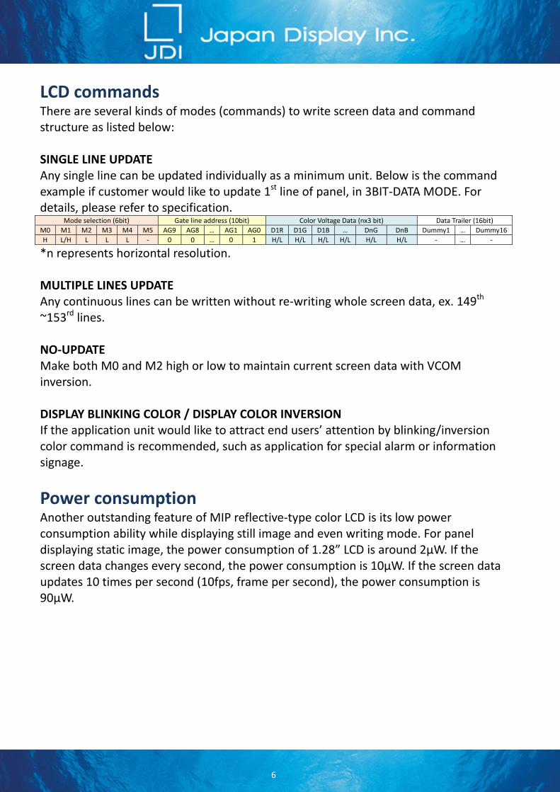
LCD commands There are several kinds of modes (commands) to write screen data and command structure as listed below: SINGLE LINE UPDATE Any single line can be updated individually as a minimum unit. Below is the command example if customer would like to update 1st line of panel, in 3BIT‐DATA MODE. For details, please refer to specification.
Mode selection (6bit) Gate line address (10bit) Color Voltage Data (nx3 bit) Data Trailer (16bit)
M0 M1 M2 M3 M4 M5 AG9 AG8 … AG1 AG0 D1R D1G D1B … DnG DnB Dummy1 … Dummy16
H L/H L L L ‐ 0 0 … 0 1 H/L H/L H/L H/L H/L H/L ‐ … ‐
*n represents horizontal resolution. MULTIPLE LINES UPDATE Any continuous lines can be written without re‐writing whole screen data, ex. 149th ~153rd lines. NO‐UPDATE Make both M0 and M2 high or low to maintain current screen data with VCOM inversion. DISPLAY BLINKING COLOR / DISPLAY COLOR INVERSION If the application unit would like to attract end users’ attention by blinking/inversion color command is recommended, such as application for special alarm or information signage.
Power consumption Another outstanding feature of MIP reflective‐type color LCD is its low power consumption ability while displaying still image and even writing mode. For panel displaying static image, the power consumption of 1.28” LCD is around 2µW. If the screen data changes every second, the power consumption is 10µW. If the screen data updates 10 times per second (10fps, frame per second), the power consumption is 90µW.
SuJDdis2. th1.cuex
TheThiin dandJapif tdes
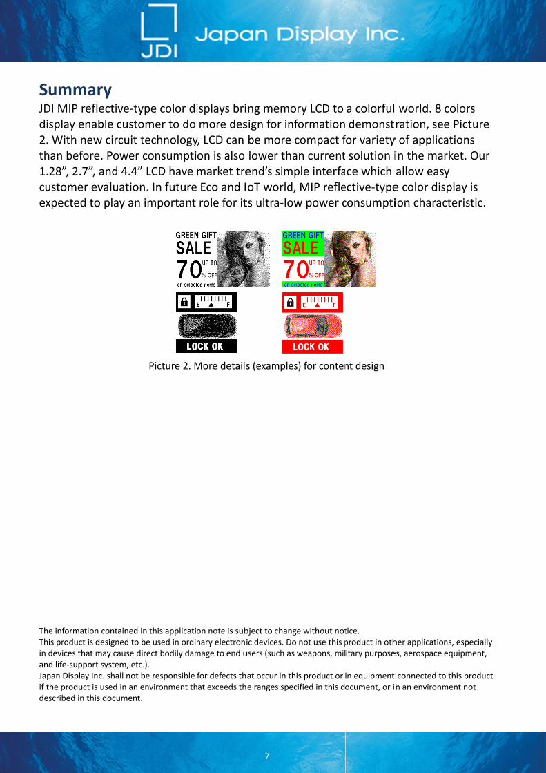
ummarDI MIP reflsplay enabWith newan before28”, 2.7”, ustomer evxpected to
e informationis product is ddevices that md life‐support pan Display Inhe product is scribed in this
ry ective‐typble customw circuit tee. Power cand 4.4” Lvaluation.o play an im
contained in designed to bemay cause diresystem, etc.).c. shall not beused in an ens document.
pe color dimer to do echnologyonsumptiLCD have m. In future mportant
Picture 2. M
this applicatioe used in ordinect bodily dam. e responsible fnvironment th
isplays brimore des
y, LCD can on is alsomarket treEco and Irole for it
More details
on note is subnary electronimage to end u
for defects that exceeds th
7
ng memosign for infbe more clower thaend’s simpoT world,ts ultra‐low
s (examples
bject to changic devices. Dousers (such as
at occur in the ranges spec
ry LCD to formationcompact fan currentple interfa MIP reflew power c
s) for conten
ge without not not use this pweapons, mil
is product or cified in this d
a colorfuldemonst
for varietysolution ice which ective‐typeconsumpti
nt design
tice. product in othitary purpose
in equipment ocument, or i
l world. 8 ration, sey of applicain the maallow ease color dision charac
her applicatioes, aerospace
t connected ton an environm
colors e Picture ations rket. Our y splay is cteristic.
ns, especiallyequipment,
o this product ment not
Related Documents


![> H D E : > H F B K K B B I H G ? H L T ? F E ? F U F J : < : F...9 l h f, l h _ ^ b g _ g g u l Z l u h ] m l _ l _ g ^ h \ Z l v l, l h [ u g Z a u \ Z l v k y ^ _ f h d](https://static.cupdf.com/doc/110x72/609921c5954b333dbe1e3203/-h-d-e-h-f-b-k-k-b-b-i-h-g-h-l-t-f-e-f-u-f-j-f-9-l.jpg)

![Z B G H < : P B H G G : L : L ? H J B Y H L D J : Y G ... · H l l _ ]. \. ^ h l _ ]. \..,,,,-..-,-17 ...](https://static.cupdf.com/doc/110x72/603b3f95fa112c10662fe1e6/z-b-g-h-p-b-h-g-g-l-l-h-j-b-y-h-l-d-j-y-g-h-l-l-h-l.jpg)