Installation Guidelines for Subsea Umbilicals API RECOMMENDED PRACTICE 17I FIRST EDITION, AUGUST 1996 EFFECTIVE DATE: OCTOBER 1, 1996 COPYRIGHT 2003; American Petroleum Institute Document provided by IHS Licensee=coflexip stena offshore/5952922001, User=, 02/19/2003 06:09:07 MST Questions or comments about this message: please call the Document Policy Management Group at 1-800-451-1584. --```,``,`,,,`,`,,`,,`,,,`,,``,-`-`,,`,,`,`,,`---

Welcome message from author
This document is posted to help you gain knowledge. Please leave a comment to let me know what you think about it! Share it to your friends and learn new things together.
Transcript
Installation Guidelines for Subsea Umbilicals
API RECOMMENDED PRACTICE 17IFIRST EDITION, AUGUST 1996
EFFECTIVE DATE: OCTOBER 1, 1996
COPYRIGHT 2003; American Petroleum Institute
Document provided by IHS Licensee=coflexip stena offshore/5952922001, User=, 02/19/2003 06:09:07 MST Questions or comments about this message: please callthe Document Policy Management Group at 1-800-451-1584.
--```,``,`,,,`,`,,`,,`,,,`,,``,-`-`,,`,,`,`,,`---
Installation Guidelines for Subsea Umbilicals
Exploration and Production Department
API RECOMMENDED PRACTICE 17I FIRST EDITION, AUGUST 1996
EFFECTIVE DATE: OCTOBER 1, 1996
COPYRIGHT 2003; American Petroleum Institute
Document provided by IHS Licensee=coflexip stena offshore/5952922001, User=, 02/19/2003 06:09:07 MST Questions or comments about this message: please callthe Document Policy Management Group at 1-800-451-1584.
--```,``,`,,,`,`,,`,,`,,,`,,``,-`-`,,`,,`,`,,`---
SPECIAL NOTES
API publications necessarily address problems of a general nature. With respect to par-ticular circumstances, local, state, and federal laws and regulations should be reviewed.
API is not undertaking to meet the duties of employers, manufacturers, or suppliers towarn and properly train and equip their employees, and others exposed, concerning healthand safety risks and precautions, nor undertaking their obligations under local, state, orfederal laws.
Information concerning safety and health risks and proper precautions with respect toparticular materials and conditions should be obtained from the employer, the manufac-turer or supplier of that material, or the material safety data sheet.
Nothing contained in any API publication is to be construed as granting any right, byimplication or otherwise, for the manufacture, sale, or use of any method, apparatus, orproduct covered by letters patent. Neither should anything contained in the publication beconstrued as insuring anyone against liability for infringement of letters patent.
Generally, API standards are reviewed and revised, reafÞrmed, or withdrawn at leastevery Þve years. Sometimes a one-time extension of up to two years will be added to thisreview cycle. This publication will no longer be in effect Þve years after its publicationdate as an operative API standard or, where an extension has been granted, upon republica-tion. Status of the publication can be ascertained from the API Authoring Department[telephone (202) 682-8000]. A catalog of API publications and materials is publishedannually and updated quarterly by API, 1220 L Street, N.W., Washington, D.C. 20005.
This document was produced under API standardization procedures that ensure appro-priate notiÞcation and participation in the developmental process and is designated as anAPI standard. Questions concerning the interpretation of the content of this standard orcomments and questions concerning the procedures under which this standard was devel-oped should be directed in writing to the director of the Authoring Department (shown onthe title page of this document), American Petroleum Institute, 1220 L Street, N.W., Wash-ington, D.C. 20005. Requests for permission to reproduce or translate all or any part of thematerial published herein should also be addressed to the director.
API publications may be used by anyone desiring to do so. Every effort has been madeby the Institute to assure the accuracy and reliability of the data contained in them; how-ever, the Institute makes no representation, warranty, or guarantee in connection with thispublication and hereby expressly disclaims any liability or responsibility for loss or dam-age resulting from its use or for the violation of any federal, state, or municipal regulationwith which this publication may conßict.
API standards are published to facilitate the broad availability of proven, sound engi-neering and operating practices. These standards are not intended to obviate the need forapplying sound engineering judgment regarding when and where these standards shouldbe utilized. The formulation and publication of API standards is not intended in any way toinhibit anyone from using any other practices.
Any manufacturer marking equipment or materials in conformance with the markingrequirements of an API standard is solely responsible for complying with all the applica-ble requirements of that standard. API does not represent, warrant, or guarantee that suchproducts do in fact conform to the applicable API standard.
All rights reserved. No part of this work may be reproduced, stored in a retrieval system, or transmitted by any means, electronic, mechanical, photocopying, recording, or other-
wise, without prior written permission from the publisher. Contact the Publisher, API Publishing Services, 1220 L Street, N.W., Washington, D.C. 20005.
Copyright © 1996 American Petroleum Institute
COPYRIGHT 2003; American Petroleum Institute
Document provided by IHS Licensee=coflexip stena offshore/5952922001, User=, 02/19/2003 06:09:07 MST Questions or comments about this message: please callthe Document Policy Management Group at 1-800-451-1584.
--```,``,`,,,`,`,,`,,`,,,`,,``,-`-`,,`,,`,`,,`---
FOREWORD
API publications may be used by anyone desiring to do so. Every effort has been madeby the Institute to assure the accuracy and reliability of the data contained in them; how-ever, the Institute makes no representation, warranty, or guarantee in connection with thispublication and hereby expressly disclaims any liability or responsibility for loss or dam-age resulting from its use or for the violation of any federal, state, or municipal regulationwith which this publication may conßict.
Suggested revisions are invited and should be submitted to the director of the Explora-tion and Production Department, American Petroleum Institute, 1220 L Street, N.W.,Washington, D.C. 20005.
iii
COPYRIGHT 2003; American Petroleum Institute
Document provided by IHS Licensee=coflexip stena offshore/5952922001, User=, 02/19/2003 06:09:07 MST Questions or comments about this message: please callthe Document Policy Management Group at 1-800-451-1584.
--```,``,`,,,`,`,,`,,`,,,`,,``,-`-`,,`,,`,`,,`---
CONTENTS
Page
1 SCOPE ........................................................................................................................ 1
2 REFERENCES............................................................................................................ 12.1 Standards ............................................................................................................ 12.2 Other References................................................................................................ 1
3 DEFINITIONS AND ABBREVIATIONS .................................................................. 13.1 DeÞnitions.......................................................................................................... 13.2 Abbreviations ..................................................................................................... 3
4 QUALITY ASSURANCE........................................................................................... 44.1 Quality Assurance System.................................................................................. 44.2 Quality Plan........................................................................................................ 44.3 Safety Plan.......................................................................................................... 4
5 UMBILICAL STORAGE ........................................................................................... 45.1 Introduction ........................................................................................................ 45.2 Methods of Storage ............................................................................................ 45.3 Protection of Umbilical Services........................................................................ 45.4 Spare Length ...................................................................................................... 55.5 Repair Kits.......................................................................................................... 55.6 Handling for Integration Tests............................................................................ 5
6 PREINSTALLATION WORK .................................................................................... 56.1 Umbilical Information........................................................................................ 56.2 Route Information .............................................................................................. 56.3 Termination Information .................................................................................... 56.4 Platform Information.......................................................................................... 66.5 Subsea Structure Information............................................................................. 66.6 Installation Analysis ........................................................................................... 66.7 Platform Site Visit .............................................................................................. 7
7 LOAD-OUT ................................................................................................................ 77.1 Introduction........................................................................................................ 77.2 Allocation of Responsibility .............................................................................. 77.3 Technical Audit of ManufacturerÕs Facilities ..................................................... 77.4 Load-Out Procedure ........................................................................................... 77.5 Pre-Load-Out Meetings...................................................................................... 77.6 Pre-Load-Out Tests ............................................................................................ 87.7 Load-Out ............................................................................................................ 87.8 Stopping and Starting the Load-Out .................................................................. 87.9 Handling of the Umbilical.................................................................................. 87.10 Load-Out Monitoring....................................................................................... 97.11 Post-Load-Out Tests.......................................................................................... 97.12 Load-Out on Reel or Carousel .......................................................................... 9
8 INSTALLATION......................................................................................................... 98.1 Introduction........................................................................................................ 9
vCOPYRIGHT 2003; American Petroleum Institute
Document provided by IHS Licensee=coflexip stena offshore/5952922001, User=, 02/19/2003 06:09:07 MST Questions or comments about this message: please callthe Document Policy Management Group at 1-800-451-1584.
--```,``,`,,,`,`,,`,,`,,,`,,``,-`-`,,`,,`,`,,`---
8.2 Vessels and Equipment....................................................................................... 98.3 Preinstallation Survey ....................................................................................... 118.4 Installation Operations ...................................................................................... 128.5 Post-Installation Survey .................................................................................... 18
9 REPAIRS TO UMBILICALS ................................................................................... 189.1 Introduction...................................................................................................... 189.2 Damage Occurring During Installation............................................................. 18
10 TESTING ................................................................................................................ 1910.1 Supervision ................................................................................................... 1910.2 Test Procedures.............................................................................................. 1910.3 Pre-Load-Out Tests ....................................................................................... 2010.4 Post-Load-Out Tests...................................................................................... 2110.5 Post-Installation Tests ................................................................................... 2110.6 Post-Hook-Up Tests ...................................................................................... 2110.7 Subsea-to-Subsea Installation ....................................................................... 21
11 UMBILICALS IN TOWED PRODUCTION SYSTEMS ...................................... 2111.1 Introduction.................................................................................................. 2111.2 Umbilical Construction................................................................................. 2111.3 Bundle Design............................................................................................... 2111.4 Handling of the Umbilical ............................................................................ 2111.5 Load-Out Monitoring.................................................................................... 2111.6 Vehicles and Equipment (Reel Deployment)................................................ 2211.7 Personnel Responsibilities ............................................................................ 2211.8 Umbilical Installation ................................................................................... 2211.9 Jumper/Riser Connections ............................................................................ 2211.10 Testing.......................................................................................................... 22
12 DYNAMIC UMBILICALS..................................................................................... 2212.1 Introduction .................................................................................................. 2212.2 Installation..................................................................................................... 22
APPENDIX AÑUMBILICAL TERMINATIONS......................................................... 25APPENDIX BÑSUBSEA PROTECTION SYSTEMS................................................... 27APPENDIX CÑTEST EQUIPMENT............................................................................. 29APPENDIX DÑCONTINGENCIES .............................................................................. 31
Tables1ÑVariations in Routing Activities ............................................................................. 102ÑDynamic Umbilical ConÞgurations ....................................................................... 23
vi
COPYRIGHT 2003; American Petroleum Institute
Document provided by IHS Licensee=coflexip stena offshore/5952922001, User=, 02/19/2003 06:09:07 MST Questions or comments about this message: please callthe Document Policy Management Group at 1-800-451-1584.
--```,``,`,,,`,`,,`,,`,,,`,,``,-`-`,,`,,`,`,,`---
I
NSTALLATION
G
UIDELINES
FOR
S
UBSEA
U
MBILICALS
1
1 Scope
This document provides guidelines for the handling, storage,and installation of permanently installed umbilicals for subseause in both static and dynamic applications. The systems mayeither be platformÐsubsea, platformÐplatform, or subseaÐsub-sea. This recommended practice is based on umbilicals thatcomply with the requirements of API SpeciÞcation 17E.
The umbilicals may have any number of individual cores thatmay carry electrical services (power or signal), Þber optic com-munications (single-mode or multi-mode), hydraulic orchemical functions, or any combination of these.
These guidelines set out the framework within which moredetailed speciÞcations and procedures must be produced toaddress the particular features of speciÞc installations as deÞnedwithin a clientÕs scope of work. It is essential that such detailedspeciÞcations clearly deÞne who is responsible for the satisfac-tory handling of the umbilical at each stage of the operations;this will depend on the nature of the contract(s) into which therelevant parties (normally the client, the umbilical manufacturer,and the installer) have entered. These guidelines indicate whatneeds to be taken into account and some possible approachesthat may be taken. It should be noted however, that the inclusionof a particular approach within the document does not imply itis the only possible approach. Other approaches may be moresuitable; this depends on the skills and equipment of the installa-tion contractor. The installer and client shall agree in writing,during the initial arrangements, where, why, and how deviationsfrom this document are permitted.
Throughout these guidelines, the words
should
and
shall
havethe following speciÞc meanings:
should
indicates a preferredcourse of action;
shall
indicates a mandatory course of action.
2 References
2.1 STANDARDS
Unless otherwise stated by the client, the following codes,standards, and guidance notes should be considered as partof this guideline.
The latest edition of each should apply. HarmonizedDocuments (HD), when available, should be used instead ofBritish Standards (BS).
IEC
1
228
Conductors of Insulated Cables
502
Extruded Solid Dielectric Insulated Power
Cablesfor Rated Voltages from 1 kV up to 30 kV
ISO
2
1402
Rubber and Plastics Hoses and Hose Assemblies-Hydrostatic Testing
4406
Hydraulic Fluid Power-Fluids-Method for CodingLevel of Contamination by Solid Particles
2.2 OTHER REFERENCES
Including but not limited to:
ClassiÞcation Society Rules and RequirementsFlag of Registry RegulationsInternational Convention for the Prevention of Pollution
from Ships, 1973 (MARPOL)International Convention of Load Lines, 1966International Convention of Safety of Life at Sea
(SOLAS), 1974 containing 1983 AmendmentsInternational Rules for the Prevention of Collision at SeaInternational Telecommunications Union Radio Regula-
tions, 1976 (ITU Geneva)
3 Definitions and Abbreviations
3.1 DEFINITIONS
For the purpose of this standard, the following deÞnitionsapply:
3.1.1 armoring:
One or more layers of helically appliedwires surrounding the laid-up functional components of anumbilical that provide mechanical strength, protection, andballast to the umbilical. The wires may be galvanized orplastic coated steel or other suitable material.
3.1.2 attenuation:
A reduction in level of the transmis-sion signal at a transmission frequency. Measured in deci-bels (dB).
3.1.3 bellmouth:
A ßared opening on the bottom of theJ-tube.
3.1.4 bend restrictor:
A device for limiting the bendradius of the umbilical, usually by mechanical means, andtypically comprised of a series of interlocking metal ormolded rings. That is also known as a
bend limiter
.
3.1.5 bend shoe:
A rigid former shaped as a sector of acircle. It ensures that the minimum bend radius of theumbilical is not infringed, particularly when overboardingumbilical during second end I or J-tube pull-ins. That is alsoknown as an arch or
overboarding chute
.
3.1.6 bend stiffener:
A device for limiting the bendradius of the umbilical by providing a local increase inbending stiffness. This is usually a molded device, some-times reinforced depending on the required duty. This issometimes known as a bend
strain reliever
.
Installation Guidelines for Subsea Umbilicals
1
1International Electrotechnical Commission, 3, rue de Varemb�, Casepostale 131, CH-1211 Gen�ve 20, Switzerland.2International Organization for Standardization, 1, rue de Varemb�, Casepostale 56, CH-1211 Gen�ve 20, Switzerland.
COPYRIGHT 2003; American Petroleum Institute
Document provided by IHS Licensee=coflexip stena offshore/5952922001, User=, 02/19/2003 06:09:07 MST Questions or comments about this message: please callthe Document Policy Management Group at 1-800-451-1584.
--```,``,`,,,`,`,,`,,`,,,`,,``,-`-`,,`,,`,`,,`---

2 API R
ECOMMENDED
P
RACTICE
17I
3.1.7 birdcaging:
A compressive instability of thearmor wires, which causes them to increase their pitch circlediameter locally.
3.1.8 bullnose:
See pull-in head (3.1.48).
3.1.9 cable:
A generic term used to describe a bundle ofinsulated electrical conductors or optical Þbers. Can also beused in place of the term
umbilical
.
3.1.10 cable engine:
A device for tensioning and pay-ing out cable.
3.1.11 capacitance:
A measurement of the electricalcableÕs ability to store electrostatic charge. This is measured inFarads.
3.1.12 carousel:
A storage container that can be rotated bya drive about a vertical axis. It incorporates an inner core struc-ture and an outer peripheral structure, both of which support theumbilical. The umbilical is stored at nominally zero tension.Carousels that do not have a structure on their outer periphery tosupport the umbilical are often known as turntables.
3.1.13 caterpillar:
Form of cable engine in which theumbilical is held between two belts.
3.1.14 Chinese finger:
Type of gripper or stopper tohold the umbilical via its outside diameter; comprised of anumber of spirally interwoven wires attached to an eye.Other types include
Siemens Stoppers, Chain Stoppers andBT(M) Stoppers
.
3.1.15 Chinese lantern:
A conÞguration for adynamic umbilical.
3.1.16 client:
The company which has a contract withthe installer for the installation of the umbilical.
3.1.17 communication cable:
See signal cable.
3.1.18 conductor:
The part of the cable along which elec-tricity can travel. It is manufactured from conductive material,such as copper, in either stranded, multi-bunched, or solid form.
3.1.19 connector:
A device used to join two electricalcables or two optical units.
3.1.20 coupling:
A device used to join two hose lengths.
3.1.21 crossing:
The means by which an umbilicalcrosses an exposed pipeline.
3.1.22 cross-talk:
The measurement of noise inducedin a signal cable due to an adjacent power cable. This ismeasured as a power ratio in two ways:
a. Differential ModeÐmeasured difference between signal pair.b. Common ModeÐmeasured with one signal line grounded,that is, measured between one signal line and ground.
3.1.23 DC conductor resistance:
Resistive value ofthe electrical conductor. Measured in ohms.
3.1.24 design working load:
Maximum tensile loadat which the umbilical functionality is unimpaired.
3.1.25 end fitting:
An attachment secured directly tothe end of a hose incorporating one-half of a metal-metalseal, used to enable connection of the hose to another pieceof equipment. See also coupling (3.1.20).
3.1.26 factory acceptance test:
The test series car-ried out on the complete umbilical system and normally wit-nessed by the client at the manufacturerÕs premises as soonas practicable after manufacture is complete. The results ofthese tests are submitted to the client for approval.
3.1.27 harmonized document:
Documents intendedfor international use, particularly those that have been rati-Þed by the appropriate international bodies.
3.1.28 hose:
A ßexible pipe that can perform functionssimilar to a rigid pipe and withstand repeated ßexure atsmall radii without adverse effects.
3.1.29 hose assembly:
A length of hose with end Þt-tings installed at each end.
3.1.30 I-tube:
A vertical pipe attached to the platformstructure through which an umbilical can be routed.
3.1.31 inductance:
A measurement of electromagneticforce induced within the electrical cable. This is measuredin Webers per ampere and has a SI derived unit of Henry.
3.1.32 installer:
The organization responsible for theinstallation of the umbilical.
3.1.33 insulation resistance:
The resistance in ohmsof a conductorÕs insulation when a constant DC potential isapplied across the cable insulation.
3.1.34 J-tube:
A vertical pipe from the seabed to theplatform topsides through which an umbilical can be routed.It begins just above the mudline and includes a bend at thebottom end (for which it is named).
3.1.35 J-tube seal:
A device for sealing the annularspace between the umbilical and the wall of the J-tube.
3.1.36 joint:
A means of joining together two lengths ofumbilical. This is also known as a joint box, splice box, orrepair joint.
3.1.37 kilometer point:
The distance along the route as laid.
3.1.38 manufacturer:
The manufacturer of the umbili-cal or its component parts.
3.1.39 manufacturer’s written specification:
Spec-iÞcation of umbilical and umbilical components supplied bythe manufacturer to the client or installer.
COPYRIGHT 2003; American Petroleum Institute
Document provided by IHS Licensee=coflexip stena offshore/5952922001, User=, 02/19/2003 06:09:07 MST Questions or comments about this message: please callthe Document Policy Management Group at 1-800-451-1584.
--```,``,`,,,`,`,,`,,`,,,`,,``,-`-`,,`,,`,`,,`---
I
NSTALLATION
G
UIDELINES
FOR
S
UBSEA
U
MBILICALS
3
3.1.40 maximum working pressure:
The maximumpressure, in bar (gauge), at which the hose is rated for con-tinuous operation. The operating pressure for a system maybe lower or equal to, but not greater than, the maximumworking pressure.
3.1.41 minimum bend radius:
The minimum radiusof curvature, measured from the outermost diameter on theinside of the bend to the center of the bend. The stated valuemay alter in differing phases of the installation operation,for example, storage, laying, trenching, and burial.
3.1.42 operating pressure:
The highest internal pres-sure at which a hose shall be used in service.
3.1.43 optical time domain reflectometry:
A faultÞnding test which uses pulse echo techniques to locatebreaks or signiÞcant change in attenuation of opticalÞbers.
3.1.44 plough:
Equipment, surface towed, for buryingumbilicals.
3.1.45 polarization index:
Ratio of electrical resis-tance measured at 10 minutes and 1 minute; used as amethod for assessing the quality of insulation.
3.1.46 power cable
:
Cables designed to transmit ACpower at electrical transmission voltages up to and includ-ing standard rated voltages U
o
/U(U
m
) = 6/10(12) kV rms
3.1.47 powered sheave:
A sheave wheel that has ameans of being driven, used for transferring the umbilical.
3.1.48 pull-in head:
A device used for terminating the endof an umbilical, so that it can be pulled up a J- or I-tube. Insome designs the terminated armors may then be used toanchor the umbilical above the J- or I-tube. It is normally astreamlined cylindrical housing into which the umbilicalarmouring is terminated and within which the ends of the ser-vice lines are contained. It can be rapidly disassembled toaccess the services for post pull-in tests and monitoring. A formof pull-in head may also be used at the subsea end of the umbil-ical. That is also known as a
bullnose
or a
pulling head
.
3.1.49 reel:
A device for storing umbilicals, also knownas a drum. It is comprised of two ßanges, separated by abarrel, with the barrel axis normally being horizontal.
3.1.50 sheath:
Any covering of the laid-up componentsby a layer of metallic, or polymeric, impervious, or non-impervious material.
3.1.51 signal cable:
Cable elements transmitting elec-trical control and communication signals up to and includ-ing standard rated voltages U
o
/U = 0.6/1 kV rms. This issometimes called
telecommunication
or
telecom cable
.
3.1.52 stab plate connector:
A multiway connectorhaving a number of protruding pins, each carrying a sepa-
rate service. It mates simultaneously with correspondingsockets in the other half of the connector when the twohalves are pulled together, usually by clamping screws.
3.1.53 supplier:
Company that supplies raw materials,ßuids, or component parts.
3.1.54 time domain reflectometry:
A fault Þndingtest which uses pulse echo techniques to locate breaks orsigniÞcant change in impedance of electrical conductors.
3.1.55 trencher:
Self-propelled equipment for buryingumbilicals. This can utilize disk cutters, chain cutters, plowshares, or jetting techniques.
3.1.56 turntable:
Similar to a carousel (q.v.) but lackingan outer peripheral structure.
3.1.57 ultimate tensile strength:
The tensile force atwhich the umbilical parts.
3.1.58 umbilical:
Collection of hoses, electrical con-ductors, and/or optical Þbers designed for subsea use.
3.1.59 weak link:
A device used to ensure that theumbilical parts at a speciÞed load.
3.1.60 webbing strop
:
A device used to grip or liftumbilicals, consisting of one or more bands of webbing.
3.1.61 U:
The rated rms power-frequency voltagebetween two conductors for which cables and accessoriesare designed.
3.1.62 Uo: The rated rms power-frequency voltagebetween each conductor and screen or sheath for whichcables and accessories are designed.
3.1.63 Um: The maximum rms power-frequency voltagebetween two conductors for which cables and accessories aredesigned. It is the highest voltage that can be sustained undernormal operating conditions at any time and at any point in asystem. It excludes temporary voltage variations due to faultconditions and the sudden disconnection of large loads.
3.2 ABBREVIATIONS
3.2.1 AC: alternating current.
3.2.2 BS: British Standard.
3.2.3 DC: direct current.
3.2.4 DP: dynamic positioning.
3.2.5 DPS: dynamic positioning system.
3.2.6 FAT: factory acceptance test.
3.2.7 IEC: International Electrotechnical Commission.
3.2.8 ISO: International Standards Organization.
3.2.9 kV: kilovolts.
COPYRIGHT 2003; American Petroleum Institute
Document provided by IHS Licensee=coflexip stena offshore/5952922001, User=, 02/19/2003 06:09:07 MST Questions or comments about this message: please callthe Document Policy Management Group at 1-800-451-1584.
--```,``,`,,,`,`,,`,,`,,,`,,``,-`-`,,`,,`,`,,`---
4 API RECOMMENDED PRACTICE 17I
3.2.10 LAT: lowest astronomical tide.
3.2.11 OTDR: optical time domain reßectometer.
3.2.12 pC: picocoulombs.
3.2.13 rms: root mean square.
3.2.14 ROV: remotely operated vehicle.
3.2.15 TDR: time domain reßectometer.
3.2.16 V: volts.
4 Quality Assurance4.1 QUALITY ASSURANCE SYSTEM
The installer shall have a recognized quality assurancesystem.
The quality assurance system shall include, at a mini-mum, the following requirements:
a. DeÞnition of personnel responsibilities and project orga-nization.b. CertiÞcation of all handling equipment.c. Inspection of installation operations.d. Pre- and post-lay testing.
4.2 QUALITY PLAN
The installer shall prepare a detailed quality plan whichdescribes how to apply the quality system to ensure that thecontracts requirements will be met. An audit plan shall bedescribed together with the procedures to be used for identi-fying any non-conformances and their causes, documentingthe Þndings, and implementing actions to prevent recurrence.
The quality plan shall ensure the adequate and docu-mented control of all work performed under the contract.
The quality plan shall provide for the identiÞcation andacquisition of the personnel resources, skills, equipment,and inspection or testing techniques that will be needed toachieve the required quality.
The quality plan shall ensure that any measuring equip-ment is adequately calibrated to traceable standards.
The quality plan shall ensure the preparation and clientapproval of documented installation inspection plans andtest plans. These plans describe where inspections or testsoccur in the work program and include the related proce-dures and acceptance criteria against which these actionsare to be carried out. The plans shall have a suitable formatfor the installer, client, and any certifying authority to indi-cate their surveillance requirements and their carrying out ofthat surveillance, for example, witness or monitor, againsteach task. The method of advising the client of the timing ofsuch activities shall be indicated, along with the lead time.
The quality plan shall describe the procedures that shallbe used to ensure that all work carried out by subcontractorsemployed by the installer is in accordance with all theinstallerÕs applicable requirements.
The quality plan shall ensure that all quality relatedrecords, test, calibration and inspection data which arerequired to be produced shall be systematically compiled,indexed, Þled, and maintained to allow ready access forretrieval and review.
4.3 SAFETY PLAN
A safety plan shall be produced to ensure the plannedoperations necessary for the installation are carried outsafely. Care shall be taken that the plan addresses the issuesraised by any risk assessment and the resulting contingencyprocedures.
5 Umbilical Storage5.1 INTRODUCTION
Upon satisfactory completion of all umbilical factoryacceptance tests, the umbilical shall be stored under coveron either a carousel, or a reel, or coiled into a storage tankuntil load-out is undertaken. The umbilical shall not bestored in direct sunlight.
5.2 METHODS OF STORAGE
Storage at the manufacturerÕs facility, or elsewhere, canbe undertaken in a number of different ways, depending onthe umbilical design, weight and length. When choosing thestorage method, consideration should be given to the fol-lowing, as a minimum:
a. Umbilical handling parameters:1. Weight and length.2. Minimum bend radius.3. Crush limitations.4. Reeling geometry.5. Size/weight of reels if stored product is to be moved.
b. Terminations:1. Rigid length.2. Weight.3. Need for bend stiffeners/limiters.
c. Necessity to monitor and test the umbilical, includinghandling and transportation for integration testing.d. Protection from accidental damage, for example, bydropped objects or moving vehicles.e. Necessity to protect the umbilical from temperatureextremes.f. Site location, for load bearing and access considerations.
5.3 PROTECTION OF UMBILICAL SERVICES
5.3.1 Hydraulic Services
In the case of umbilicals containing hoses, each hose shallbe Þlled with the ßuid speciÞed in Section 10, and the hoseends shall be capped off. The hoses shall be pressurized to70 bar (gauge) unless otherwise speciÞed in the manufac-
COPYRIGHT 2003; American Petroleum Institute
Document provided by IHS Licensee=coflexip stena offshore/5952922001, User=, 02/19/2003 06:09:07 MST Questions or comments about this message: please callthe Document Policy Management Group at 1-800-451-1584.
--```,``,`,,,`,`,,`,,`,,,`,,``,-`-`,,`,,`,`,,`---
INSTALLATION GUIDELINES FOR SUBSEA UMBILICALS 5
turerÕs written speciÞcation, and the manufacturer shall logthe pressure in each hose string on a weekly basis until load-out. Any pressure variations logged which cannot beaccounted for by temperature variation shall be furtherinvestigated and documented.
5.3.2 Electrical Services
Electrical cores, if present, shall be capped off and sealedto avoid water ingress.
5.3.3 Optical Fibres
Optical Þber tails, if present, shall be suitably protected toavoid any possibility of water ingress or mechanical damage.
5.4 SPARE LENGTH
A spare length may be delivered as a separate item or may bepart of the total umbilical as an overlength. The precautionsdescribed in Section 5.3 shall be applied to the spare (or over)length. The remaining length shall be clearly and indeliblymarked with the project title and the length on the reel.
5.5 REPAIR KITS
Any repair kits (repair joints) shall be stored under coverin suitable containers to prevent damage or deterioration ofquality. The containers shall be clearly labelled. The label-ling shall include the expiration date of any parts of the kit(for example resins or solvents) that have limited shelf lives.
5.6 HANDLING FOR INTEGRATION TESTS
It may be necessary to carry out integration testing ofcontrol umbilicals. In the case of short, relatively lightumbilicals, this may be undertaken away from the manufac-turer's premises at the control system supplier or elsewhere.Considerable care shall be taken to ensure that any umbili-cal which is transported and handled is done so withoutinfringing any of the handling or storage parameters orcausing damage to the outer covering of the umbilical.
The manufacturer shall prepare a suitable procedure fortransportation and handling. This procedure shall state whois responsible for the handling of the umbilical at eachstage. All transportation and handling shall be carried out inaccordance with these approved procedures.
After an umbilical is transported or used in integrationtests, the complete umbilical FAT shall be repeated as perSection 14 of API SpeciÞcation 17E, including a visualinspection of the outside of the umbilical, and the documen-tation of results.
6 Preinstallation Work6.1 UMBILICAL INFORMATION
The manufacturer shall provide to the installer, at the ear-
liest possible time, at a minimum, the following umbilicalinformation:
a. A cross-sectional drawing, with details of the outer cov-ering material.b. The design working loads.c. The ultimate tensile strength.d. The axial stiffness.e. The bending stiffness.f. The weight in air (hoses empty).g. The weight in air (when Þlled with the ßuid(s) speciÞedin Section 10).h. The weight in water (when Þlled with the ßuid(s) speci-Þed in Section 10).i. The length (and tolerance on/accuracy of length).j. Details of length markings applied and their direction.k. The overall diameter (minimum nominal and maximum).l. The minimum bend radius under installation conditions.m. The load-torque characteristics (torque-balance).n. The crushing load per unit length.o. The allowable combination of axial steady state andfatigue loads, and number of cycles, to which the umbilicalmay be subjected.p. Repair joint dimensions and Þtting procedure.q. The pressure to be applied to the hoses during installation.r. The Maximum Working Pressure and hose sizes.s. Power/signal/optical characteristics.t. Details of storage prior to load-out.u. ConÞrmation of longitudinal line for twist monitoring.v. Friction characteristics of umbilical outer covering.
6.2 ROUTE INFORMATION
The client shall supply to the installer, at the earliest possiblestage, environmental and preliminary survey information(including geophysical data and planned pipelines, umbilicalsand subsea structures) regarding the proposed route. This willenable the installer to select suitable vessels and installationtechniques and to take account of any crossings required.
6.3 TERMINATION INFORMATION
The client or manufacturer, as applicable, shall providethe installer with information on the proposed system of ter-mination of the umbilical. This information shall include thefollowing, at a minimum:
a. The dimensions.b. The weight in air.c. The weight in water.d. Details of functional interfaces with subsea structure.e. The lifting arrangements designed into the termination,weaklinks, junction boxes and in-line splices.f. Hang-off location temporary and permanent arrange-ments on the platform.
COPYRIGHT 2003; American Petroleum Institute
Document provided by IHS Licensee=coflexip stena offshore/5952922001, User=, 02/19/2003 06:09:07 MST Questions or comments about this message: please callthe Document Policy Management Group at 1-800-451-1584.
--```,``,`,,,`,`,,`,,`,,,`,,``,-`-`,,`,,`,`,,`---
6 API RECOMMENDED PRACTICE 17I
6.4 PLATFORM INFORMATION
The client shall provide the installer with the relevantdetails of the platform(s). These include, at a minimum:
a. Plan/elevation/envelope of jacket and topsides.b. I/J-tube dimensions, geometry and locations on the plat-form for padeyes, shackles and winches.c. I/J-tube bellmouth sealing details.d. Pipeline and riser positions.e. Other activities scheduled for the work site during theinstallation operations.f. Detail drawings relating to the top of J-tube and sur-rounding area, including rooÞng over J-tube.
The client shall allow the installer free and unrestrictedaccess to the platform and the surrounding area, except asspeciÞcally stated. The client shall inform the installer ofthe permit to work system and the nature and location of anyknown obstructions.
Suitable sites on the platform shall be provided, as neces-sary, for the installer to mount appropriate vessel position-ing system stations, installation aids, and pull-in winches.Details of services available on the platform (if any) shallalso be provided.
6.5 SUBSEA STRUCTURE INFORMATION
The client shall provide the installer with details of thesubsea structure and equipment so that the subsea pull-in ofthe umbilical termination can be planned.
6.6 INSTALLATION ANALYSIS
The installer shall, as part of the installation engineeringphase, carry out a dynamic installation analysis on theumbilical. This analysis shall be used to establish the load-ing imposed on the umbilical due to its self weight, currentsand laying vessel motion. Additionally, the analysis shallexamine the limitations imposed on the umbilical due totrenching operations, rock dumping, crushing due to lay cat-erpillars and engines, and the load-out, overboarding andpull-in operations. Limiting installation conditions due toseabed stability considerations shall be considered. Theinstallation analysis shall aid in the generation of therequired installation.
The calculation methodology adopted, and the use of anysoftware packages, should be documented.
The analysis shall be used to establish the followinginformation:
a. Allowable limits in the offset between the touch downpoint of the umbilical on the seabed and the vessel as afunction of seastate and current.b. The variation of tension and curvature along the umbili-cal as a function of seastate and current.c. Tension and curvature time series plots for a number of
points along the umbilical, including the points establishedas having the maximum and minimum values of tension andminimum radii of curvature.d. Maximum allowable vessel motions to avoid overstress-ing the umbilical.e. Residual tension from plowing-in.f. The catenary at the bottom of the I/J-tube from vessel tobellmouth.g. Limitations on the pull-in at the subsea termination.h. Limitations on unsupported span shapes during load-outto preclude loop formation.i. Methods of handling overlengths near terminations.
The limits shall be established to be compatible with theumbilical design loads, minimum bend radius and allowablecrushing load as supplied to the installer by the manufacturer.The manufacturer shall provide to the installer any previousinstallation analysis results, and the results shall be compared.
The client shall provide the installer with informationabout the degree of protection required. The installer shalldemonstrate that by laying the umbilical on the surface ofthe seabed, and trenching, burial rockdumping, mattressingor otherwise, this requirement can be met.
The installer shall state the limiting sea states for eachpart of the installation procedure. This shall include the lim-iting sea state and length of time for which the vessel can behove-to while the umbilical is being laid, without causingdamage to the umbilical. The conditions which shall causethe umbilical to be abandoned shall be clearly stated. Ifnecessary, the proposed method of installation shall bealtered to avoid infringing the allowable umbilical limita-tions. Other weather-related considerations include condi-tions for the pull-in, handling, and deployment ofterminations and launch or recovery of ROVs, trenchers,and plows.
The installer shall demonstrate that the proposed installa-tion vessel with its handling equipment can meet therequirements of the installation, including repair if this iscontained within the contingency procedures.
Similarly, the burial equipment and methodology shall bejustiÞed for the operation, and limits stated. Particular atten-tion shall be paid to the forces applied to the umbilical by itsinteraction with the equipment.
The installer shall also calculate the maximum tensileload levels that will be required to be applied to the umbili-cal during the pull-in operation, and to demonstrate thatthey are acceptable for the umbilical design. The calculationshall consider, at a minimum, the following factors:
a. Umbilical weight (in air and water) and bending stiffness.b. Catenary conÞguration due to the vessel stand-off dis-tance, length of cable on the seabed (if any) and hence back-tension at the I/J-tube entrance.c. Cable contact with the I/J-tube over the whole I/J-tubelength.
COPYRIGHT 2003; American Petroleum Institute
Document provided by IHS Licensee=coflexip stena offshore/5952922001, User=, 02/19/2003 06:09:07 MST Questions or comments about this message: please callthe Document Policy Management Group at 1-800-451-1584.
--```,``,`,,,`,`,,`,,`,,,`,,``,-`-`,,`,,`,`,,`---
INSTALLATION GUIDELINES FOR SUBSEA UMBILICALS 7
d. The physical geometry of the I/J-tube.e. The force required to pull-in the I/J-tube seal and bendstiffener, if they have been preinstalled on the cable prior toa pull-in.f. Maximum allowable deck load (pull-in and hang-off).
In all cases, suitable monitoring methods and equipmentshall be available and procedures shall be developed tocover contingencies, should these arise.
6.7 PLATFORM SITE VISIT
The installer shall visit the platform(s) to examine the I/J-tube(s) and hang-off positions to decide where to positionthe pull-in winch, temporary rigging, and testing and moni-toring spread. The requirements on equipment regardingsafety zoning and other applicable requirements shall alsobe established. If ROV operations are scheduled from theplatform, the feasibility of these shall also be assessed.
7 Load-out7.1 INTRODUCTION
The load-out operation is the loading of the umbilical(s)onto the installation vessel from the manufacturerÕs facili-ties. Occasionally, for example if the umbilical has beenused for integration tests with the control system, load-outmay not occur from the manufacturerÕs facilities.
7.2 ALLOCATION OF RESPONSIBILITY
It is essential that responsibility for the satisfactory han-dling of the umbilical at every stage shall be clearly deÞned.The exact points in the operation at which responsibility istransferred from one party to another must be stated andagreed to before operations commence.
The following sections assume that after FAT, all opera-tions are controlled by the installer.
7.3 TECHNICAL AUDIT OF MANUFACTURER’SFACILITIES
The installer shall visit the manufacturerÕs facilities andinspect the equipment which the manufacturer intends touse for their portion of the load-out operation, and to assessthe acceptability of the facility for the operation.
The matters to be considered in the course of the visitinclude the following, at a minimum:
a. Lay vessel1. Constraints on the draft of the vessel and other dimensions.2. Mooring and maneuverability requirements.3. Craneage operations from the vessel.
b. Umbilical storage facilities1. Method of storage.2. Access to facility.3. Arrangement of terminations.
4. Limitations on handling from storage due to umbilical parameters (weight, minimum bend radius, crush loadlimitations).5. Protection during storage.
c. Onshore umbilical handling systems:1. Type of system.2. Method of control and communications.3. Manning requirements (likelihood of 24 hour working).4. Rated pay-out speed.5. Interface with storage facility.6. Interface with vessel umbilical handling system.7. Requirement to provide additional equipment (portable cable engine, etc.).8. Limitations on handling due to umbilical parameters (weight, minimum bend radius, crush load limitations).9. Craneage and lifting facilities for handling terminations.
The availability of onsite manpower and support func-tions, together with any local labor agreements, shall bereviewed.
7.4 LOAD-OUT PROCEDURE
The installer shall write a load-out procedure describingthe proposed operation and identifying all the onshoreequipment to be used. (The manufacturer shall provide pro-cedures for the onshore load-out equipment for inclusion inthe installerÕs procedure.) The procedure shall identifywhich end of the umbilical needs to be loaded Þrst, and theorder of umbilical loading in cases being loaded. If any rigidjoints and rigid terminations are incorporated in the umbili-cal, the procedure shall detail the method and equipment tobe used in handling these.
7.5 PRE-LOAD-OUT MEETINGS
The installer and the manufacturer shall meet to establishthe basis for the operation and to conÞrm the point of hand-over of responsibility for the umbilical. A number of mattersneed to be reviewed and emphasized, including:
a. Chain of command for the operation and point of hand-over of responsibility.b. Responsibilities and stafÞng for the load-out.c. Interfaces between the installer and the manufacturer.d. Communications procedures.e. Review of the load-out procedure and contingency.f. Timetable for load-out, including timetable for necessaryaccess permits.g. Handling of terminations and any intermediate joints.h. Required assistance from the manufacturer for pre- andpost-load-out tests.i. Provision of all necessary information to the vessel mas-ter for the calculation of vessel stability.j. Safety procedures and the generation of a safety plan.
COPYRIGHT 2003; American Petroleum Institute
Document provided by IHS Licensee=coflexip stena offshore/5952922001, User=, 02/19/2003 06:09:07 MST Questions or comments about this message: please callthe Document Policy Management Group at 1-800-451-1584.
--```,``,`,,,`,`,,`,,`,,,`,,``,-`-`,,`,,`,`,,`---
8 API RECOMMENDED PRACTICE 17I
7.6 PRE-LOAD-OUT TESTS
These tests are required to be carried out only if the com-plete umbilical assembly has been transported from themanufacturerÕs works to another site, or has been stored formore than three months.
In either of these circumstances, it is essential that thepoint at which responsibility for the umbilical is transferredfrom one party to another (normally from manufacturer toinstaller) is stated and agreed upon before operations com-mence.
These tests shall be carried out prior to the load-out oper-ation, but with sufÞcient time allotted that rectiÞcationcould be carried out if necessary. If there is no pre-load-outtest, the installer shall be invited to witness the FAT.
7.7 LOAD-OUT
Following berthing of the vessel, the person in charge ofthe load-out shall arrange for:
a. A brieÞng for all personnel involved in the operation toexplain the procedures to be adopted, the communicationsprocedures and the timetable for the load-out. Particularemphasis should be placed on the safety plan for the operation.b. Examination of calibration and functional testing recordsof the onshore and vessel based equipment to be used andconÞrmation that these are all current.c. A messenger rope to be passed from the shore to the ship.
Upon satisfactory completion of the preliminary activi-ties, the load-out can commence. Normally, a messengerrope is used as a lead-in for the umbilical and the umbilicalis passed from its storage onshore along the handling sys-tem to the vessel, where it is re-stored on the vessel storagesystem.
7.8 STOPPING AND STARTING THE LOAD-OUT
All operations shall be coordinated by the person respon-sible for the load-out and shall aim to prevent the possibilityof damage to personnel, assets, or umbilical. If in the viewof an operator involved in the operation there is a problemor the possibility of a potential problem arising, he shallhave the authority to cause the load-out to be halted in acontrolled manner. Once the operation has been stopped,only the person responsible for the load-out shall authorizere-commencement. This authorization shall only be givenonce the responsible person is satisÞed that the problem hasbeen resolved, or the potential problem averted.
7.9 HANDLING OF THE UMBILICAL
The handling of the umbilical during the load-out shall becarried out and monitored in a manner to ensure that theumbilical and its associated accessories are not subjected toany damage.
7.9.1 Twist
The umbilical shall be visually monitored at all timesthroughout the operation to observe the presence of twist.The presence of signiÞcant twist shall be investigated.
7.9.2 Minimum Bend Radius
The bend radius of the umbilical shall at all times begreater than the value of minimum bend radius as speciÞedby the manufacturer.
7.9.3 Lifting the Umbilical
If it is necessary to sling the umbilical, bend shoes orwebbing strops shall be used. At no time shall wire ropes beused for this purpose. When strops are used, care shall betaken to avoid infringing the minimum bend radius require-ment or inducing buckling, by using multiple strops.
The use of Chinese Þngers shall be permitted.
7.9.4 Transfer Across Spans
When the umbilical is transferred across any open spaceunsupported, the tension shall be such that the resulting cat-enary does not infringe the minimum bend radius. At eachend of the span, the umbilical shall be supported by suitablyradiused bend shoes, sheaves, chutes or bell mouths.
The catenaries shall be carefully monitored, and the load-out speeds altered accordingly, to ensure that the catenarytensions, in addition to the shapes, remain acceptable and inagreement with the values contained in the load-out proce-dure, and that there is no possibility of the umbilical kinkingor forming a loop.
If the storage facility is not directly alongside the point atwhich the vessel is berthed, a gantry may be used for trans-porting the umbilical to the vessel. Alternatively, roller traysor caterpillars may be used.
7.9.5 Terminations
Terminations shall be handled using the lifting devicessuch as eye bolts or lifting lugs designed into them. Han-dling of large terminations shall require special consider-ation. When carrying out lifting operations onterminations, care shall be taken that there is no inadvertentremoval of the protective coating on the item due to scratch-ing, chaÞng, or similar effects. The operation shall beplanned to ensure that the load-out handling of the termina-tion does not introduce unacceptable levels of tension, twist,or bending into the umbilical at the termination.
The subsea termination shall be fastened on board thevessel in a position that allows access for testing of theumbilical and in the orientation required (with respect to thevertical) to ensure subsequent satisfactory pull-in and con-nection to the subsea structure.
COPYRIGHT 2003; American Petroleum Institute
Document provided by IHS Licensee=coflexip stena offshore/5952922001, User=, 02/19/2003 06:09:07 MST Questions or comments about this message: please callthe Document Policy Management Group at 1-800-451-1584.
--```,``,`,,,`,`,,`,,`,,,`,,``,-`-`,,`,,`,`,,`---
INSTALLATION GUIDELINES FOR SUBSEA UMBILICALS 9
7.9.6 Weak Link
Prior to commencement of the load-out, the weak link(s),if Þtted, shall be checked to verify that its override system(if applicable) is in place and that there is no possibility ofinadvertent actuation during load-out or subsequent laying.
7.10 LOAD-OUT MONITORING
7.10.1 Electrical
The DC conductor continuity shall be continuously moni-tored during the load-out operation. The system used shallbe capable of recording brief breaks in continuity, forinstance by use of a high frequency response chart recorder.Should there be any loss of continuity, the operation shall behalted and a DC Conductor Resistance Test on individualcables shall be carried out in accordance with the require-ments in Section 10. In the event of a failure, a TimeDomain Reßectometry Test may be carried out as speciÞedin Section 10.
7.10.2 Hydraulic
Each hose shall be pressurized to 70 bar (gauge) unlessotherwise speciÞed in the manufacturerÕs written speciÞca-tion and this pressure shall be maintained to within ± 5 per-cent for the duration of the umbilical load-out. The pressureshall be continually monitored with a chart recorder. Ambi-ent temperature shall be recorded. Any variations in mea-sured pressure outside these limits shall cause cessation ofthe load-out for further investigation.
7.10.3 Optical Fibers
The attenuation shall be continuously monitored duringthe load-out operation using an OTDR. Should there be anychange in attenuation or any apparent discontinuity in theÞbers, the operation shall be halted and an investigationshould be carried out.
7.10.4 Visual Tests
7.10.4.1 Umbilical Condition
The umbilical shall be examined during the load-outoperation for signs of distortion, kinking, surface damage,raised diameters, bird-caging of armor wire, or otherdefects. The entire umbilical length shall be examined. Anydefect shall be reported to the client.
7.10.4.2 Umbilical Length
The installer shall ensure that the length loaded out ontothe vessel is as speciÞed and that length markings asrequired for the subsequent lay operations are marked onthe umbilical. The equipment to measure the length shall be
calibrated to a standard and the measuring procedures docu-mented according to the manufacturerÕs written speciÞca-tion.
7.11 POST-LOAD-OUT TESTS
The test details are given in Section 10.
7.12 LOAD-OUT ON REEL OR CAROUSEL
In cases when the umbilical is not transferred fromonshore carousel/reel to vessel carousel/reel, (that is, thestorage system is the installation system), load-out monitor-ing is not required. However, a full series of post-load-outtests shall be carried out. If the operation involves an earliertransfer from storage system to storage system, the monitor-ing of that operation shall be identical to the load-out moni-toring.
8 Installation8.1 INTRODUCTION
Installation procedures shall be written by the installer inaccordance with the quality plan. There are a number of dif-ferent types of lay which can be used, including:
a. Free lay onto the seabed.b. Simultaneous lay and bury.c. Lay and post bury.d. Lay into a predug trench.
The burial can be carried out either with a plow or a tren-cher, or left to occur naturally. Additionally, there are anumber of different routings which are possible:
a. SurfaceÐsurface (platformÐplatform).b. SurfaceÐsubsea.c. SubseaÐsubsea.
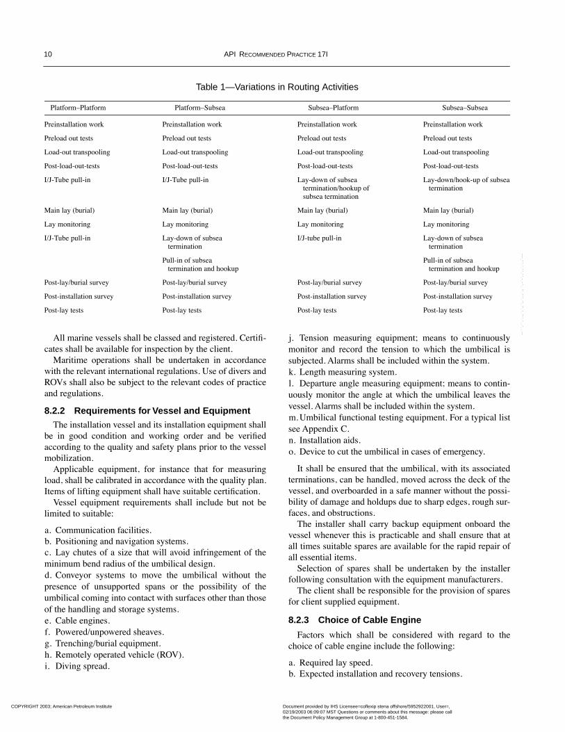
Consequently some of the details of the operations vary,but there are a number of common features in all types ofoperation which are described in the following sections. Themajor activities for each of the routings are shown in Table 1.
8.2 VESSELS AND EQUIPMENT
8.2.1 Introduction and Applicable Specifications
All marine vessels and equipment shall be capable of per-forming their required function, shall meet their speciÞca-tion as declared by the installer to the client, and shall beoperated by specialist personnel according to an Interna-tional Safety Management Code (ISM Code).
The umbilical installation vessel shall comply with allcodes, standards, and regulations of the relevant statutoryauthorities. A duplex DP system shall be required, and priorto mobilization in the Þeld, sea trials with the DP systemmay be required.
COPYRIGHT 2003; American Petroleum Institute
Document provided by IHS Licensee=coflexip stena offshore/5952922001, User=, 02/19/2003 06:09:07 MST Questions or comments about this message: please callthe Document Policy Management Group at 1-800-451-1584.
--```,``,`,,,`,`,,`,,`,,,`,,``,-`-`,,`,,`,`,,`---
10 API RECOMMENDED PRACTICE 17I
All marine vessels shall be classed and registered. CertiÞ-cates shall be available for inspection by the client.
Maritime operations shall be undertaken in accordancewith the relevant international regulations. Use of divers andROVs shall also be subject to the relevant codes of practiceand regulations.
8.2.2 Requirements for Vessel and Equipment
The installation vessel and its installation equipment shallbe in good condition and working order and be veriÞedaccording to the quality and safety plans prior to the vesselmobilization.
Applicable equipment, for instance that for measuringload, shall be calibrated in accordance with the quality plan.Items of lifting equipment shall have suitable certiÞcation.
Vessel equipment requirements shall include but not belimited to suitable:
a. Communication facilities.b. Positioning and navigation systems.c. Lay chutes of a size that will avoid infringement of theminimum bend radius of the umbilical design.d. Conveyor systems to move the umbilical without thepresence of unsupported spans or the possibility of theumbilical coming into contact with surfaces other than thoseof the handling and storage systems.e. Cable engines.f. Powered/unpowered sheaves.g. Trenching/burial equipment.h. Remotely operated vehicle (ROV).i. Diving spread.
j. Tension measuring equipment; means to continuouslymonitor and record the tension to which the umbilical issubjected. Alarms shall be included within the system.k. Length measuring system.l. Departure angle measuring equipment; means to contin-uously monitor the angle at which the umbilical leaves thevessel. Alarms shall be included within the system.m. Umbilical functional testing equipment. For a typical listsee Appendix C.n. Installation aids.o. Device to cut the umbilical in cases of emergency.
It shall be ensured that the umbilical, with its associatedterminations, can be handled, moved across the deck of thevessel, and overboarded in a safe manner without the possi-bility of damage and holdups due to sharp edges, rough sur-faces, and obstructions.
The installer shall carry backup equipment onboard thevessel whenever this is practicable and shall ensure that atall times suitable spares are available for the rapid repair ofall essential items.
Selection of spares shall be undertaken by the installerfollowing consultation with the equipment manufacturers.
The client shall be responsible for the provision of sparesfor client supplied equipment.
8.2.3 Choice of Cable Engine
Factors which shall be considered with regard to thechoice of cable engine include the following:
a. Required lay speed.b. Expected installation and recovery tensions.
Table 1—Variations in Routing Activities
PlatformÐPlatform PlatformÐSubsea SubseaÐPlatform SubseaÐSubsea
Preinstallation work Preinstallation work Preinstallation work Preinstallation work
Preload out tests Preload out tests Preload out tests Preload out tests
Load-out transpooling Load-out transpooling Load-out transpooling Load-out transpooling
Post-load-out-tests Post-load-out-tests Post-load-out-tests Post-load-out-tests
I/J-Tube pull-in I/J-Tube pull-in Lay-down of subsea Lay-down/hook-up of subsea termination/hookup of termination subsea termination
Main lay (burial) Main lay (burial) Main lay (burial) Main lay (burial)
Lay monitoring Lay monitoring Lay monitoring Lay monitoring
I/J-Tube pull-in Lay-down of subsea I/J-tube pull-in Lay-down of subsea termination termination
Pull-in of subsea Pull-in of subsea termination and hookup termination and hookup
Post-lay/burial survey Post-lay/burial survey Post-lay/burial survey Post-lay/burial survey
Post-installation survey Post-installation survey Post-installation survey Post-installation survey
Post-lay tests Post-lay tests Post-lay tests Post-lay tests
COPYRIGHT 2003; American Petroleum Institute
Document provided by IHS Licensee=coflexip stena offshore/5952922001, User=, 02/19/2003 06:09:07 MST Questions or comments about this message: please callthe Document Policy Management Group at 1-800-451-1584.
--```,``,`,,,`,`,,`,,`,,,`,,``,-`-`,,`,,`,`,,`---
INSTALLATION GUIDELINES FOR SUBSEA UMBILICALS 11
c. Diameter of umbilical and any joints.d. Availability of deck area.e. Reliability of engine and level of system redundancyrequired.f. Necessity for more than one engine.g. Method and accuracy of measurement of tension.h. Tolerance on control of tension.i. Method and accuracy of measurement of gripping force.j. Allowable gripping forces on umbilical.k. Method and accuracy of measurement of umbilicallength.l. Wear on gripping components.
It should be noted that the friction characteristics of theouter covering of the umbilical are extremely importantwhen considering the cable engine. If there are concernsthat the combination of cable engine and wet umbilicalouter covering (for example, polyethylene) may requirehigh crushing loads to overcome the low coefÞcient of fric-tion, then handling trials should be considered. Consider-ation should also be given to the frictional characteristics ofthe outer covering in relation to the armoring.
When the umbilical is stored in a carousel or in a cabletank it is inadvisable to rely upon a single linear cableengine for braking, unless the design is one that fails safe. Anadditional (redundant) method of restraining pay-out shouldbe provided; for example, a second cable engine or a capstan.
8.2.4 Choice of Burial Equipment
The choice of equipment is governed by a number of con-siderations. These include the following:
a. Type of installation planned:1. Simultaneous lay and bury.2. Free-lay and post-bury.3. Lay into predug trench (with or without subsequent burial).
b. Seabed operations:1. Soil type (hard, mid-range, soft) and conditions.2. Presence of boulders and boulder size.3. Cutting requirements/plowing forces.4. Trench/burial depth.5. Need to pass obstructions such as pipeline crossings.6. Necessity to work close to structures.
c. Machine characteristics:1. Limitations on launch/recovery of system due to sea-state.2. Length of time to launch/recover.3. Limitations on system operation post-launch due to surface conditions.4. Rate of operation through soil type(s) to be encountered.5. Reliability and redundancy.6. Seabed weight and maneuverability.7. Necessity for diver intervention.
8. Necessary deck spread and launch equipment.9. Potential risk of damage to umbilical.10. Umbilical monitoring equipment (cameras, sensors, load measuring).11. Machine sensors (sonar, pipe trackers).12. Ability to accommodate bundled (piggybacked) umbilicals.
The reaction forces within, or the geometry through, themachine shall not damage the umbilical or its outer covering.
8.3 PREINSTALLATION SURVEY
8.3.1 Introduction
Before commencing the umbilical installation theinstaller shall carry out a preinstallation survey along theproposed route and width of corridor, unless the client hasarranged for others to undertake it.
The preinstallation survey shall be carried out usingequivalent positioning and navigation equipment to thatwhich will be used during the installation operations.
The survey shall identify any seabed obstructions anddebris that may be hazardous to the umbilical or mayimpede its installation. The installer shall propose suitablemethods of seabed preparation for those areas in whichpreparation is considered necessary and shall carry out thatpreparation.
8.3.2 Requirements of Survey
Consideration shall be given during the preinstallationsurvey to the following activities:
a. Surveillance of the planned route using a side scan sonaror an ROV in order to conÞrm the data from earlier activi-ties and to survey the right-of-way for the umbilical installa-tion vessel.b. ConÞrmation of the position of any adjacent pipelines,cables, umbilicals, or other structures.c. Establishment of the position and identity of any piecesof debris which lie along the proposed route and in a deÞnedcorridor on either side of it. Removal of debris where neces-sary and feasible should be undertaken subsequently.d. Survey of possible route deviations which may be neces-sary to avoid debris, to comply with contingency plans, or touse up excess umbilical length prior to termination laydown.e. Survey of the platform(s) environs, including the I/J-tubes, and the area of termination laydown.f. ConÞrmation that any preinstalled messenger wires andÞttings are in good condition and usable.g. ConÞrmation that all subsea preparations for any pipe-line crossings are satisfactory.h. Deployment of temporary installation aids where neces-sary; for example, at turn points on the route, mud mat-tresses at subsea termination positions.
COPYRIGHT 2003; American Petroleum Institute
Document provided by IHS Licensee=coflexip stena offshore/5952922001, User=, 02/19/2003 06:09:07 MST Questions or comments about this message: please callthe Document Policy Management Group at 1-800-451-1584.
--```,``,`,,,`,`,,`,,`,,,`,,``,-`-`,,`,,`,`,,`---
12 API RECOMMENDED PRACTICE 17I
i. Deployment of transponders or beacons at critical posi-tions, for example, pipeline crossings, on the route and atthe target area for laydown of the umbilical subsea termination.j. Bathymetric, sub-bottom proÞler and side scan sonarsurveys of the route.k. Determination of the water depth along the route length,and subsequent correction to LAT by making allowance forthe predicted tide during the survey.l. Conduct of a magnetometer survey along the route. Ifthere are any anomalies between this survey and the resultsof the sonar survey, they should be further investigated.
8.3.3 Reporting
The output from the survey shall be as follows:
a. A report on the proposed route, including full details ofany hazards identiÞed, seabed preparations required anddebris to be cleared. This shall highlight any discrepanciesbetween information supplied by the client to the installerand the survey Þndings.b. A set of survey video tapes, which include the cameraposition on the display.c. A route chart, indicating water depth, possible routedeviations and the positions of any hazards or debris.
8.4 INSTALLATION OPERATIONS
8.4.1 Personnel Responsibilities
The individuals responsible for the execution of eachactivity, the veriÞcation against speciÞed requirements andthe authority with regard to acceptance of satisfactory com-pletion of activities shall be speciÞed in the quality plan asstated in Section 4.
The interaction between the various personnel directlyinvolved in the installation depends on the speciÞc activitybeing carried out. Consequently, the details of such interac-tions shall be speciÞed in the installerÕs procedures for theproject.
8.4.2 I/J-Tube Pull-in Operations
8.4.2.1 Introduction
In the course of installing umbilicals, it is usually neces-sary to carry out at least one I or J-tube pull-in operation. Inthe case of platform-platform links between two platforms,two such operations are necessary.
8.4.2.2 Preparatory Work
Prior to the pull-in, a number of preparations shall be car-ried out in order to ensure that the operation can be com-pleted successfully. These preparations are the following:
a. Review of calculations (see Section 6.4), to establishlimit loads during the pull-in operation.
b. Gauging (pigging) of the tube to check that it is clear ofobstructions and fouling.c. Placement of messenger put into tube (if one is notalready in place). This can be done by blowing one downthe tube.d. Establishment of pull-in equipment and personnel onplatform. This includes installing the winch, and its associ-ated rigging, including the load monitoring and umbilicalfunctional testing equipment, and preparing the hang-offarrangement.e. Check of communications facilities.
Umbilical terminations are described in Appendix A.
8.4.2.2.1 Weather Window for Pull-in
The availability of a suitable weather window shall beestablished prior to initiating operations. The required win-dow shall take account of the predicted duration of the pull-in and lay operation, vessel and equipment capability, andthe results of installation analyses regarding sea state versusumbilical loading.
Due regard shall be given to the length of time for whichthe vessel can remain hove-to without causing damage tothe deployed umbilical.
8.4.2.2.2 Initiation of Pull-in Operations
The vessel shall contact the existing facilities as soon aspossible on route to the installation site.
Following successful completion of the platform prepara-tory activities described in Section 8.4.2.2, the pull-in oper-ation may proceed, and the vessel may approach theplatform.
On entering the zone around the platform, vessel opera-tions shall become subject to all the regulatory requirementsthat pertain to operations on the platform.
8.4.2.2.3 Visual Survey
Following the arrival of the lay vessel in the vicinity of theplatform, a visual check of the seabed and I/J-tube entranceshall be carried out by either ROV or diver. The purpose ofthis is to check both the physical condition of the I/J-tube, theseabed conditions, and the proÞle on the route into the I/J-tube to conÞrm the Þndings of the preinstallation survey.
If the I/J-tube is Þtted with a blind ßange at the bottom, itis necessary to remove this ßange. A transponder may beattached to the I/J-tube bellmouth at this time if one isrequired for subsequent operations.
The identity, position, and condition of the messengerwire shall be established at this stage. If the messenger wireis attached to a clump weight the exact position of theclump weight shall be determined. This operation is particu-larly important if there is more than one I or J-tube in closeproximity, and therefore more than one clump-weighted
COPYRIGHT 2003; American Petroleum Institute
Document provided by IHS Licensee=coflexip stena offshore/5952922001, User=, 02/19/2003 06:09:07 MST Questions or comments about this message: please callthe Document Policy Management Group at 1-800-451-1584.
--```,``,`,,,`,`,,`,,`,,,`,,``,-`-`,,`,,`,`,,`---
INSTALLATION GUIDELINES FOR SUBSEA UMBILICALS 13
messenger wire. It is also essential to ensure that there is nopossibility of two or more messenger wires becomingentangled in subsequent operations.
8.4.2.3 Recovery of the Messenger Wire
On the platform the winch pull-in wire shall be fastenedto the messenger wire at the top of the I/J-tube. The bottomend of the messenger wire shall then be attached to the wireof the winch positioned on the deck of the lay vessel. Thedeck winch is then used to recover the messenger wire ontothe deck of the vessel as the platform winch pays out. It maybe necessary to use a signiÞcant tension when the messen-ger wire is attached to a diaphragm in the I/J-tube bell-mouth.
Once the end of the messenger wire is on the deck, theclump weight (if present) is removed and the recovery pro-cedure continued until the end of the pull-in wire is on thedeck. The end of the umbilical can then be attached to thewire.
8.4.2.4 Umbilical Pull-in
The pull-in head may be overboarded from the vessel andthe umbilical paid out from the vessel. The vessel positionshall be adjusted to produce the required catenary so that theumbilical enters the I/J-tube at the correct angle and that theumbilical is not dragged excessively along the seabed.
Monitoring of the pull-in operation shall be undertakenusing:
a. The tension monitoring equipment on the platform.b. The tension monitoring equipment on the vessel.c. The ROV video camera, which will visually monitor theumbilical in the vicinity of the I or J-tube entry, to establishthe catenary shape, extent of seabed contact (if any), umbil-ical bend radius and umbilical twist. The umbilical shallhave frequent length markings in this region to assist obser-vation.d. The amount of umbilical paid out.
Pull-in tension shall be carefully monitored and com-pared with the previously calculated values. Any increase intension above that previously agreed shall cause the opera-tion to be suspended and the cause of the increase to beinvestigated.
At the point at which the pull-in head is about to enter theJ-tube bellmouth, particular emphasis shall be placed on theinformation provided by the ROV video camera, to removeany possibility of snagging the pull-in head. Similar careshall also be taken as the I/J-tube seal and bend stiffener (ifthey are preinstalled on the umbilical) approach the I/J-tubeentrance and their required position in the I/J-tube. Smallvessel movements may be required at this point to ensurethat entry is unimpeded.
8.4.2.5 Securing the Umbilical on the Platform
On arrival at the relevant deck level, the umbilical shall besecurely fastened. The permanent hang-off arrangement,either a mechanical termination of the armor wires or pot-ting off of the wires, can be Þtted as soon as the pull-in iscompleted, if the termination has not been attached to theumbilical prior to the pull-in. Alternatively, when the per-manent method would take a long period of time, the fasten-ing can be made temporarily using split clamps, ChineseÞngers, and so forth so that the testing and lay can proceedwithout delay. Later the permanent hang-off can be con-structed.
8.4.2.6 I/J-Tube Bottom Seal/Bend Stiffener
On most installations the bottom of the J-tube is sealed,although this is installation speciÞc.
The seal may already be in place at the end of the pull-inoperation if preinstalled onto the umbilical prior to the pull-in. In some cases the seal is operational at the end of thepull-in without any further intervention. On other occasions itmay be necessary for diver or ROV to make the seal operative.
Where there is no preinstalled seal, it is necessary to Þt itafter the pull-in and hang-off have been completed.
8.4.2.7 I/J-Tube Chemical Protection
It is normal practice to introduce chemical inhibitors, bio-cides, and oxygen scavengers into the I/J-tube to provideprotection to the I/J-tube material. All chemicals used andtheir ultimate combination within the tube shall be con-Þrmed at an early stage as compatible with the umbilicalmaterials with which they come into contact.
8.4.2.8 I/J-Tube Top Seal
Where the umbilical hang-off does not seal the top of theI/J-tube, it may be necessary to Þt a suitable top seal. Thetop seal and hang-off arrangements shall have provision forthe introduction of chemical treatments, if required.
8.4.2.9 Removal of Temporary Rigging
Following commencement of the lay-away from the plat-form, the pull-in winch and temporary rigging can be dis-mantled and removed, although it is recommended that thisnot be carried out until a successful post-installation test hasbeen undertaken. Any localized damage to protective coat-ings on the platform should be made good.
8.4.2.10 Second End Pull-in
This operation is required in the case of platformÐplat-form umbilicals, and also in the case where the lay of a plat-formÐsubsea umbilical commences at the subsea end.
The I/J-tube pull-in at the second end, although similar in
COPYRIGHT 2003; American Petroleum Institute
Document provided by IHS Licensee=coflexip stena offshore/5952922001, User=, 02/19/2003 06:09:07 MST Questions or comments about this message: please callthe Document Policy Management Group at 1-800-451-1584.
--```,``,`,,,`,`,,`,,`,,,`,,``,-`-`,,`,,`,`,,`---
14 API RECOMMENDED PRACTICE 17I
many ways, can be more complicated than a pull-in opera-tion at the start of the lay due to the presence of the umbili-cal which has already been laid and the catenary to thevessel. Irrespective of the details of the operation, the proce-dures used shall include the requirements of close tensioncontrol and visual monitoring of the catenary, the seabed umbil-ical subject to displacement, and the entrance to the I/J-tube.
8.4.3 Movement of Vessel Away from the Platform
In the case of a Þrst end pull-in, the lay vessel shall pro-ceed to lay umbilical along the planned route to clear theimmediate vicinity of the platform as soon as the pull-in iscomplete. In the case of simultaneous lay and bury opera-tions, this will also necessitate launching the burial vehicleprior to the lay-away, unless this has been done prior to thepull-in. While this is under way, platform connection ofumbilical test and monitoring equipment shall be carriedout, when the monitoring is being undertaken from the plat-form. Commencement of the main lay of the umbilicalalong the route beyond the immediate vicinity of the plat-form shall not proceed without conÞrmation that the umbili-cal testing has been satisfactorily completed, the monitoringequipment is connected and operational and pressurization(if applicable) has been achieved unless otherwise dictatedby the procedures.
For a second end pull-in the vessel shall move away at thecompletion of the pull-in.
8.4.4 Lay-down of Subsea Termination (First End)
(If the initial part of the operation is installation of a sub-sea termination, this is carried out in place of the I/J-tubepull-in operations described in the previous sections.)
Any necessary work required to prepare the seabed shallbe carried out. The termination is overboarded and loweredto its designated position on the seabed. The terminationshall be Þtted with a transponder and light-sticks to aid posi-tion monitoring. Depending on the design of the system, thedesignated position may be the Þnal position, or a subse-quent pull-in to a manifold may be required. As the termina-tion is lowered, the umbilical position and tension shall becarefully monitored and controlled to avoid the generationof slack within the umbilical length. Once the termination ison the seabed and suitably secured, the umbilical routingaway from the termination shall be as designed.
As an alternative for a Þrst end subsea termination, thelay-away method may be used. In this case the lay vesselshall pass the Þrst end umbilical termination underneath thedrilling rig and into the moonpool. In the moonpool there isa guidebase or Christmas tree to which the umbilical will beconnected. After relevant testing (see Section 10), the guide-base or Christmas tree with umbilical connected is loweredto the wellhead and secured. After conclusion of this opera-tion, the lay vessel will commence the main laydown of the
umbilical along the route. At the vessel selection stage, itshall already have been veriÞed that the vessel can maintainposition during the above mentioned activities under thedesign environmental conditions allowed for that operation.
Considerable care needs to be taken if the termination isof a design which may give rise to the presence of signiÞ-cant hydrodynamic forces due to currents, vessel heave, orthe wake from thrusters. These forces may induce large ratesof twist into the umbilical by virtue of termination rotation.
8.4.5 Lay Route
The umbilical lay route shall be shown on umbilical routealignment charts. These charts shall show the way-points,the coordinates of changes in direction of the route and thecorridor within which the umbilical shall be laid. The chartsshall also detail the extent and location of any additionalprotection required, such as tubular protectors or mattress-ing, the presence of other umbilicals and risers, pipelinesand pipeline crossings, and dimensioned target areas forlay-down of the umbilical subsea terminations.
8.4.6 Handling Requirements for the Main Lay
The major mechanical requirements during the main layare to avoid the following:
a. Introducing too much slack in the vicinity of the touch-down position, by virtue of low tension/large departureangle, to preclude the possibility of loop (ÒhockleÓ) formation.b. Infringing the minimum bend radius at the touchdownpoint, to stop over-bend of the umbilical.c. Introducing large rates of twist into the umbilical, toreduce the probability of loop formation and birdcaging.d. Applying excess tension, which may overstress theumbilical.e. Flexing the umbilical, close to the overboarding point,where catenary loads are at their maximum, and at thetouchdown point for extended periods to exclude the likeli-hood of fatigue failures of the umbilical structure.
8.4.7 Vessel Positioning to Achieve Required Touchdown
The umbilical touchdown point shall be continually visu-ally monitored by the ROV to verify that the umbilical isbeing laid within the required corridor as deÞned on theroute alignment charts. This shall be achieved by means ofreference to the ROVÕs on-board acoustic transponder. TheROV high-resolution sonar (if Þtted) can also be used toconÞrm by reference to other seabed features that the umbil-ical remains within the deÞned corridor. If the ROV sufferstechnical problems of a nature which means that it cannotcarry out the monitoring function then the lay shall be stopped.
It is particularly important to control length when the ves-sel is altering course. In the situation when the route is
COPYRIGHT 2003; American Petroleum Institute
Document provided by IHS Licensee=coflexip stena offshore/5952922001, User=, 02/19/2003 06:09:07 MST Questions or comments about this message: please callthe Document Policy Management Group at 1-800-451-1584.
--```,``,`,,,`,`,,`,,`,,,`,,``,-`-`,,`,,`,`,,`---
INSTALLATION GUIDELINES FOR SUBSEA UMBILICALS 15
curved, the vessel is moved from one alter course point tothe next by entering the coordinates of each location usingthe umbilical lay reference, allowing for umbilical touch-down layback. The ROV shall monitor the touchdown posi-tion to ensure the umbilical continues to be laid in thecorrect corridor. Subsea beacons laid during the preinstalla-tion survey can assist with positioning at critical pointsalong the route.
If the vessel is headed in the direction of lay with theumbilical being laid over a stern chute, any deviation of theumbilical lead from directly astern of the vessel route due tothe presence of cross currents or tides can easily be esti-mated. If it is considered necessary, a small vessel offset canbe applied at any subsequent turn point to take account ofany tidal current. If a crab-lay is undertaken, the offsetbetween the vessel and the touchdown point, as indicated bythe ROV transponder, should be used to make an estimate ofthe effects of currents and tides so that the route can bealtered to take account of this.
In very deep water the touchdown point may have to bemonitored with sidescan sonar or an ROV deployed from aseparate survey vessel.
8.4.8 Control and Monitoring of Length Laid
It is necessary to monitor umbilical length paid outagainst distance travelled along the planned route in order todo the following:
a. Detect whether excessive umbilical length is being laid.b. Allow the lay of a Þxed umbilical length over theplanned route while ensuring correct positioning of the sub-sea terminations in the predetermined laydown target area.
A computation of the umbilical length paid out shall bemade continuously. Suitable entries at each marked distancepoint on the umbilical shall be used. The umbilical shall bemarked in accordance with API SpeciÞcation 17E, with 10-meter marking intervals at each end and 100-meter mark-ings over the central length.
As each umbilical marking passes a speciÞed datum markon the vessel, a navigation Þx shall be taken and the follow-ing information recorded and/or calculated:
a. Time and date.b. Reference number of navigation Þx.c. Coordinates of overboarding point.d. Coordinates of touchdown point.e. Distance along route as laid (KP).f. Umbilical marked length at datum.g. Umbilical length measurement equipment reading.h. Overlength since last calculation.i. Cumulative overlength.j. Distance to end of layk. Umbilical remaining inboard of datum mark.l. Catenary tension at overboarding point.
m. Mean umbilical pay-out rate.n. Comments.
Some of this can be precalculated to facilitate rapid sim-ple checks that the lay is proceeding to plan.
Details regarding length control at completion of lay aregiven in Section 8.4.1.1.
8.4.9 Integrity Monitoring During Lay
Lay monitoring may be undertaken from the platform ifthe Þrst operation is an I or J-tube pull-in. When the Þrstoperation is a lay of a subsea termination, lay monitoringmust to be carried out from the installation vessel.
8.4.9.1 Electrical
The conductor continuity shall be continuously moni-tored during the lay operation. In the event that there is anyloss of continuity, the operation shall be halted and a DCconductor resistance test on the individual cables shall becarried out in accordance with the requirements laid downin Section 10. In the event of a failure, a time domain reßec-tometry test may be carried out as speciÞed in Section 10.
6.4.9.2 Hydraulic
Each hose shall be pressurized to 70 bar (gauge) unlessotherwise speciÞed in the manufacturer's written speciÞca-tion, and this pressure shall be maintained for the durationof the umbilical lay. The pressure in each hose shall be con-tinually monitored with a chart recorder. Should there beany unexplainable loss of pressure, or if the behavior of onehose string relative to the rest is markedly different, theoperation shall be halted, and the cause of the pressure lossinvestigated.
8.4.9.3 Fiber Optic
Each optical Þber shall be continuously monitored usingan OTDR. Should there be a signiÞcant change in attenua-tion, or a loss of continuity, the operation shall be halted,and the cause of the Þber problem investigated.
8.4.9.4 Visual Tests
The umbilical shall be examined during the operation forsigns of distortion, kinking, surface damage, bird-caging ofarmor wire, or other defects deÞned in the installers qualityplan. The examination shall be for 100 percent of the umbil-ical length. Any defect shall be reported to the client.
8.4.10 Burial Operations
Burial of an umbilical may be required for protectionagainst dropped objects or Þshing activities, or for stabilityrequirements.
The burial operation depends on the type of equipmentused, and whether the operation is a simultaneous lay andburial, or a post-lay burial.
COPYRIGHT 2003; American Petroleum Institute
Document provided by IHS Licensee=coflexip stena offshore/5952922001, User=, 02/19/2003 06:09:07 MST Questions or comments about this message: please callthe Document Policy Management Group at 1-800-451-1584.
--```,``,`,,,`,`,,`,,`,,,`,,``,-`-`,,`,,`,`,,`---
16 API RECOMMENDED PRACTICE 17I
Plowing or trenching shall be performed as a single passoperation. If the required burial depth is not achieved, thenthe required protection shall be provided by other means.Application of the additional protection shall be carried outso as not to put the umbilical at any risk.
Other methods of protection are listed in Appendix B.Deployment/recovery of plows and trenchers shall not take
place within a radius of 50 meters of any subsea facility.
8.4.10.1 Monitoring During the Burial Operation
The burial operation shall be continuously monitoredboth by the on-vehicle instrumentation and from the sur-face, using both ROV and surface survey, navigational, andsonar systems.
At a minimum, the following parameters shall be moni-tored:
a. The tow force (plow).b. Loads induced on the umbilical.c. ConÞguration of the umbilical in front and through thevehicle.d. Burial depths.e. Vehicle and vessel positions.f. Area ahead of the vehicle for obstructions.
If at any time the instrumentation or visual inspectionsindicate that damage to the umbilical may have occurred,the installer shall interrupt the trenching or plowing opera-tion and perform a diver and/or ROV video survey of thedamaged area.
8.4.10.2 Interaction With Umbilical
The minimum bend radius of the umbilical during theburial operation shall not be less than the minimum bendradius of the umbilical as per the manufacturerÕs writtenspeciÞcation.
8.4.11 Approach to Subsea Termination Position (Second End)
As the subsea termination laydown position is approached,it is necessary to ensure arrival at the correct point, by care-fully monitoring the lay distance remaining and gaining orlosing route length over umbilical length as required. A tran-sponder shall be deployed on the termination during laydownto give accurate positioning at seabed touchdown.
Any contingency plans for route deviations shall havebeen agreed upon prior to mobilization as part of the initialdevelopment of procedures.
Having continually compared the umbilical length laidwith the position on the route, approximately 1Ð2 kilome-ters from the laydown target area the length of umbilicalremaining to be laid in comparison with the planned routedistance still to go shall be assessed. If necessary a revised
route shall then be produced to accommodate the umbilicallength remaining. This procedure shall be repeated and theroute revised at appropriate distances (typically 100Ð200meters initially reducing to 25 meters when within 200meters of the laydown position). By adoption of this tech-nique any residual umbilical length can be used up gradu-ally, thereby avoiding the need to deal with large amounts ofexcess umbilical length in the area where the termination isto be put down. When the umbilical is to be buried, it isdesirable to bury as much as possible to minimize the lengthrequiring alternative protection.
Alternatively, in the case of congested areas, the approachadopted might be to limit putting excessive length on theseabed. In that case the umbilical is laid towards the Þnalway-point at a short, measured distance from the Þnal tar-get. It can then be determined what the actual overlength ofthe umbilical is. Subsequently, in the Þeld, the overlengthcan be reduced, the umbilical terminated and testing carriedout (see Section 10).
8.4.12 Lay-down of Subsea Termination
The dimensions and location of the target area for the ter-mination laydown shall be marked on the route alignmentchart and physically on the seabed with a transponder. Insoft soil conditions a mattress may have been laid as part ofthe preinstallation work.
The Þnal laydown of the umbilical shall be carried out sothat the umbilical lies on the seabed with the extra lengtharranged in an S, a C, or other form so that the pull-in doesnot cause the umbilical to infringe its minimum bend radius.
A predeployment test of the umbilical and subsea termi-nation may be carried out, although if the previous testingand monitoring activities are satisfactory, the slightlyincreased risk to the umbilical may make this activityunnecessary.
Preparations should now be made to overboard the termi-nation. Light-sticks and a transponder shall be attached tothe end of the winch wire or crane hook and/or the termina-tion to facilitate a properly controlled deployment of the endtermination onto its target area.
The termination shall be lowered into the water, with thevessel maneuvering as required to maintain the desiredumbilical laydown route. As the termination arrives within 5meters of the seabed the operation should halt to conÞrmthat a satisfactory laydown shall be achieved. If necessary,lift the termination and reposition the vessel so as to achievethe desired laydown position and heading.
8.4.13 Pull-in of Subsea Termination
The subsea termination should now be pulled into its Þnalposition in the subsea structure.
In the case of a stab plate connector, the act of pulling thetermination into its Þnal position shall cause the functional
COPYRIGHT 2003; American Petroleum Institute
Document provided by IHS Licensee=coflexip stena offshore/5952922001, User=, 02/19/2003 06:09:07 MST Questions or comments about this message: please callthe Document Policy Management Group at 1-800-451-1584.
--```,``,`,,,`,`,,`,,`,,,`,,``,-`-`,,`,,`,`,,`---
INSTALLATION GUIDELINES FOR SUBSEA UMBILICALS 17
connections to be made. Alternatively the functional con-nections may be made by jumper hoses and/or cables, whichis effected after pull-in. In the case of a stab plate connector,the angular orientation of the termination with respect to thesubsea structure is critical.
A detailed procedure shall be prepared for the Þnal stagesof pull-in depending on the particular design.
Factors to be considered include:
a. Details of mechanical fastening.b. Installation of cathodic protection straps.
Once the termination is in the speciÞed Þnal position, thenecessary mechanical fastenings shall be installed.
In the case of the stab plate connectors, this completes theconnections and the pull-in. When jumpers are to be used,these shall now be installed paying due attention to any tem-porary jumper connections that may be required as part ofthe ßushing or test procedures.
8.4.14 Pipeline Crossings
When a crossing is necessary, the proposed crossingdesign and applicable procedures shall be properly docu-mented and permission obtained from the pipeline owner.The proposed crossing design should include positive sepa-ration between pipe and umbilical.
As the lay vessel approaches the crossing area, the loca-tion of the crossing shall be checked. Visual observation ofthe area by ROV and use of sonar shall also be undertaken,and the touchdown point carefully monitored over the cross-ing. A transponder shall be installed at the crossing toensure that an accurate location Þx can be made, therebyachieving the correct placement of the umbilical at thecrossing point.
For burial operations, it is necessary to transition theplow/trencher back to the surface of the seabed short of thecrossing point and return the vehicle back to the vessel deckand secure it there for the crossing. No attempt shall bemade to ßy the plow/trencher over the pipeline, and it shallbe fastened on deck during the crossing. Plowing/trenchingcan then be restarted on the other side of the crossing.
Further protection is necessary to ensure that the umbili-cal is not vulnerable to damage at the crossing.
8.4.15 Arming of Weak Link
The arming of the weak links, if Þtted, shall be carried outon completion of the following:
a. Burial of the umbilical by plow or trencher (if required).b. Second end pull-in and hook-up of termination.c. Attachment of any weak link restraints to the structure.
Yet this arming shall be carried out before the installationtest, which in this context may be a post-pull-in test or aÞnal system functional test.
8.4.16 Completion of Protection
After completion of burial of the umbilical by plow ortrencher, there will still be lengths of umbilical whichremain exposed due to limitations on the positions in whichthe plow or trencher can be deployed. These limitations ondeployment, and subsequent exposed umbilical lengths,may be located at the following:
a. The approach to the I/J-tube(s) at the platform(s).b. The approach to the subsea termination.c. Any pipeline crossings.d. Any parts of the route that are of too small a radius forthe trencher or plow to negotiate and are consequently laidwithout burial.e. Repair joints where a spare length or repair has beeneffected following damage during installation.f. Regions where the trencher has been recovered forchange-out of cutting teeth and the like.
During the initial installation planning, a decision shall bemade whether or not to protect the exposed umbilical in theabove-listed areas (8.4.16, items aÐf). Protection may beaccomplished by sandbagging, laying mattresses over theumbilical, or alternatively by rockdumping over the umbili-cal. A further method that is used in the vicinity of the I/J-tube is applying molded tubular protectors to the umbilicalprior to its being overboarded.
8.4.17 Post-lay Survey
In the case of a simultaneous lay and bury operation thepost-lay and post-burial surveys are combined.
The post-lay survey shall be carried out (usually by theinstaller) to conÞrm the as-laid position of the umbilical,and to conÞrm the absence of damage to the umbilical.
The survey shall be carried out either as a separate opera-tion using visual observation from an ROV when a lay andpost-burial operation is undertaken, or from the plough/tren-cher when a simultaneous lay and bury operation is performed.
The video recording shall include a display overlay show-ing the camera position coordinates and heading.
The resulting video records shall be supplied to the client.
8.4.18 Post-burial Survey
A survey of the entire route of the umbilical immediatelyfollowing burial shall be undertaken (most normally by theinstaller). The survey shall show that the burial operationhas been carried out in accordance with the speciÞedrequirements.
The survey shall be carried out by ROV and shouldinclude the following:
a. A video survey of the entire length of the umbilical route.b. IdentiÞcation of the positions of any unburied or unsup-ported lengths of the umbilical.
COPYRIGHT 2003; American Petroleum Institute
Document provided by IHS Licensee=coflexip stena offshore/5952922001, User=, 02/19/2003 06:09:07 MST Questions or comments about this message: please callthe Document Policy Management Group at 1-800-451-1584.
--```,``,`,,,`,`,,`,,`,,,`,,``,-`-`,,`,,`,`,,`---
18 API RECOMMENDED PRACTICE 17I
If shown to be necessary, the installer shall carry out suit-able remedial work, so that the installation meets the agreedburial requirements. In these circumstances, the relevantareas shall be re-videoed.
The documentation shall include the following items:
a. A written report of the survey Þndings.b. A full set of videotapes of the survey.c. Charts showing the as-buried position and depth of burialof the umbilical.
8.4.19 Post-pull-in Test
These tests shall be performed once the subsea termina-tion has been pulled into its Þnal position. In the case of astab plate connector, the act of pulling the termination intoits Þnal position shall cause the functional connections to bemade. In this event, the post-pull-in test becomes the post-hook-up test.
The test details are given in Section 10.
8.4.20 Post-hook-up Test
These tests shall be performed once the subsea functionalconnections have been made. The installer shall ensure byliaison with the control system vendor that these tests shallcause no damage to the control system.
The test details are given in Section 10.
8.4.21 Retrieval of Installation Aids
The installer shall be responsible for retrieving all tempo-rary subsea installation aids after successful completion ofinstallation of the umbilical.
8.4.22 Contingencies
There are a number of potential problems which mayarise during the course of an installation operation for whichcontingency planning is required. The installer shall carryout a risk assessment study to cover foreseeable occur-rences, including common mode failures, and produce suit-able procedures.
Examples of some of the matters that need to be addressed,and possible approaches, are contained in Appendix D.
8.5 POST-INSTALLATION SURVEY
The installer shall carry out a survey along the entire sub-sea route of the umbilical including the I/J-tube bell-mouth(s) and subsea termination. The survey shall becarried out using a side scan sonar and/or a video cameramounted on an ROV, and equipped with a remote monitor sothat the client may view the survey as it takes place.
The survey shall verify that the umbilical and associatedaccessories such as seals, weak link, bend restrictor, andprotection have been installed in accordance with the speci-
Þcation requirements, and that all temporary installationaids have been removed.
The post-installation survey shall also include all umbili-cal terminations and anchor points which shall be inspectedfor leakage and damage.
The results of the survey, together with the continuous,unedited original recording of the whole inspection shall bepart of the as-built documentation. The recording shallinclude a display/overlay showing the equipment positioncoordinates and heading, so that the as-laid position of allitems is recorded.
If the survey shows that the client speciÞcation has notbeen met (for instance, inadequate protection), the installershall undertake appropriate remedial work.
The various surveys (post-lay/post-burial) may be com-bined into a single post-installation survey.
9 Repairs to Umbilicals9.1 INTRODUCTION
If damage occurs to the umbilical in the course of installa-tion, or sometime after installation, it may be necessary toeffect a repair. The approach adopted depends on the stage atwhich the problem occurs and the length of umbilical whichhas suffered the damage. It is also possible that the repairmight be required following an emergency abandonment(cutting) of the umbilical. Each repair shall be installationspeciÞc. The installer, in conjunction with the manufacturer,shall prepare procedures for the repair of the umbilicalprior to the commencement of the installation.
9.2 DAMAGE OCCURRING DURING INSTALLATION
Damage which occurs during installation may manifestitself either from the monitoring of the services within theumbilical or from visual observation. At the time the dam-age is suspected, the installation operation shall be sus-pended for further detailed investigation and assessment ofthe problem. If required, further testing shall be undertakento assess the nature and extent of the problem, and the exactlocation of the fault if it is not obvious.
Parameters such as vessel and touchdown position, dateand time, and environmental conditions when the lay opera-tion is suspended shall be noted for reference in any subse-quent investigation.
Once it has been established that there is damage to theumbilical that would impair its function, the installer shallprepare a fully detailed written damage report, along with asuggested course of action for repair or recovery.
Umbilical recovery shall then be carried out. The opera-tion will continue until the damaged portion of umbilical ison the deck of the vessel.
COPYRIGHT 2003; American Petroleum Institute
Document provided by IHS Licensee=coflexip stena offshore/5952922001, User=, 02/19/2003 06:09:07 MST Questions or comments about this message: please callthe Document Policy Management Group at 1-800-451-1584.
--```,``,`,,,`,`,,`,,`,,,`,,``,-`-`,,`,,`,`,,`---
INSTALLATION GUIDELINES FOR SUBSEA UMBILICALS 19
10 Testing10.1 SUPERVISION
The installer shall appoint a QA/QC representative whoshall be responsible for supervising and documenting eachtest. A certiÞcate shall be produced for each test, recordingall appropriate test data. Test failures shall be clearly indi-cated on the certiÞcate.
The installer shall ensure that adequate safety equipmentand procedures in accordance with the safety plan are avail-able during the testing.
10.2 TEST PROCEDURES
All tests referenced in this section are in accordance withAPI SpeciÞcation 17E. For further details on umbilical testsrefer to API SpeciÞcation 17E unless otherwise agreedbetween client and installer.
The following tests shall be carried out as required in Sec-tions 10.3, 10.4, 10.5, and 10.6 for pre-load-out, post-loadout, post-installation and post-hookup.
10.2.1 Electrical
10.2.1.1 General
Unless otherwise speciÞed these tests shall be carried outon each completed electrical power and signal unit containedwithin the electrical cable bundle of the completed umbilical.
10.2.1.2 DC Conductor Resistance Test
The corrected DC conductor resistance shall be within ± 2percent of the values obtained during the umbilical factoryacceptance tests.
10.2.1.3 Insulation Resistance
Each conductor shall be tested for insulation resistance.Insulation resistance shall be measured and calculated inaccordance with IEC 502. The value of insulation resistanceshall not be less than the value as deÞned in the manufac-turerÕs written speciÞcation.
10.2.1.4 High Voltage Test
Each insulated conductor shall be high voltage DC tested.The DC withstand voltage for communication conductorsshall be three times Uo.
Each insulated conductor shall withstand a minimum DCwithstand voltage between conductor and all other conduc-tors and armouring for a period of not less than 5 minutes.At the end of this period, the leakage current shall be mea-sured and shall not exceed the value stated in the manufac-turerÕs written speciÞcation.
10.2.1.5 Time Domain Reflectometry
A time domain reßectometry (TDR) trace shall be obtainedfor each conductor, and where possible, from both ends.
The width of the pulse shall allow the whole cable to bescanned.
Graphs produced shall have detailed all the major pointssuch as start and end of the cable and joints (if present).
The TDR traces obtained shall be compared with thoseobtained during the FAT and any changes accounted for tothe clientÕs satisfaction.
10.2.2 Hydraulic
10.2.2.1 General
Unless otherwise speciÞed these tests shall be carried outon each completed hose assembly including any intermedi-ate couplings and end Þttings that form part of the umbilicalbundle.
From the FAT, carried out in accordance with API Speci-Þcation 17E, and environmental conditions during installa-tion, it shall be decided whether the hose pressure test(Section 10.2.2.3), the pressure decay test (Section 10.2.2.4)or both shall be carried out offshore to demonstrate umbili-cal integrity. The decision arrived at shall be justiÞed at thetime of producing test procedures.
10.2.2.2 Test Fluid
The installer shall be responsible for frost protection ofthe ßuids. When there is judged to be any risk of freezing, achange in either ßuid or concentration may be necessary.The installer shall take all reasonable precautions to ensurethat contamination of the test ßuid is prevented and all testßuid shall be new and unused. Manufactured hose lengthsshall be capped off with screwed caps at all times when test-ing is not in progress. Tests shall be carried out at ambienttemperature.
10.2.2.2.1 Hydraulic Control Hoses
The test ßuid shall be the speciÞed system control ßuidnew, unused and Þltered to 5 microns absolute. The testßuid shall be guaranteed clean to ISO 4406 class 15/12.
10.2.2.2.2 Chemical Injection Hoses
The test ßuid shall be a solution of potable water plus 25percent monoethylene glycol, Þltered to 5 microns absolute.As necessary, suitable biocides shall be added.
10.2.2.3 Hose Pressure Test
A proof test as speciÞed in ISO 1402 shall be carried outon each Þnal hose assembly, including all Þttings and cou-plings that are in the umbilical bundle.
COPYRIGHT 2003; American Petroleum Institute
Document provided by IHS Licensee=coflexip stena offshore/5952922001, User=, 02/19/2003 06:09:07 MST Questions or comments about this message: please callthe Document Policy Management Group at 1-800-451-1584.
--```,``,`,,,`,`,,`,,`,,,`,,``,-`-`,,`,,`,`,,`---
20 API RECOMMENDED PRACTICE 17I
The test pressure shall be 1.5 times (or according toinstallerÕs written speciÞcation which shall be based on themanufacturerÕs data) the maximum working pressure, andmust remain constant to within ± 5 percent for a period of60 minutes after stabilization of pressure has been achieved.The maximum rate at which the pressure is raised or low-ered shall be 10 bar/minute. If the pressure is not heldwithin the speciÞed tolerance then the reason for the exces-sive decay shall be investigated. The test pressure and ßuidtemperature shall be measured at both ends of the hose,where possible.
Note: The test pressure for the post-hook-up hydraulic tests shall be 1.0 timesthe operating pressure for control lines, and 1.1 times for chemical lines.
10.2.2.4 Pressure Decay Test
Each hose assembly shall be connected to a hydraulicsupply at one end-Þtting, taking care to obtain a leak-freeseal. A pressure transducer connected to a chart recorderwith an event marker shall be installed at the end-Þtting notconnected to the hydraulic supply. The chart recorder shallbe used to record the pressure for the entire test.
The hose shall be Þlled with the speciÞed test ßuid, bledof all entrapped air and the remaining end-Þtting closed off.
The chart recorder shall be started and the entire hosepressurized to the test pressure speciÞed in Section 10.2.2.3(with a rate of pressure rise that is no greater than 10 bar/minute) and isolated from the pressure supply. After aperiod of 15 minutes repressurize the hose to the test pres-sure and isolate from the supply. Allow a further period of15 minutes before repressurizing to the test pressure a thirdand Þnal time. The test shall be complete 15 minutes afterthe Þnal repressurization. The start of each repressurizationshall be marked on the pressure trace using the eventmarker.
Note: The test pressure for the post-hook-up hydraulic tests shall be 1.0 timesthe operating pressure for control lines, and 1.1 times for chemical lines.
The pressure at each successive event marker on the traceshall be higher than the pressure at the previous markers,and the pressure trace after the last pressurization mustshow clear signs of leveling out. (Typical industry practiceis that the initial pressure decay should be no more than onethird of the test pressure.)
10.2.2.5 Flushing and Cleanliness Test
Once the umbilical has been fully installed, that is, laid-down, pulled-in, buried (if required), prior to or post-hook-up, depending on the system design, each hose shall beßushed according to the procedure laid out below.
Upon satisfactory completion of all other acceptance teststhe installer shall ßush each hydraulic control hose assem-bly individually with the speciÞed test ßuid.
All equipment for carrying out and monitoring this test
shall have cleanliness levels equal to, or better than, ISO4406 15/12.
Each hose shall be ßushed with a minimum of two timesthe theoretical hose volume. In the case of a direct hydrauliccontrol system the ßushing requirement may be relaxed.
The ßow rate should be sufÞcient to ensure turbulent ßowthroughout the hose. If this proves impossible to achieve onvery long hoses without exceeding the maximum workingpressure at the hose inlet, then the highest ßow rate possiblesubject to this constraint should be used. A Reynolds Numberof 10000 shall be used when calculating the ideal ßow rate.
If gas-assisted ßushing procedures are adopted to achieveturbulent ßow in long hoses, then the installer shall Þrstdemonstrate to the client through experiment that the per-meation of the gas through the hose liner over the timeperiod of testing is insigniÞcant, and not liable to cause blis-tering or other damage to the hoses.
10.2.3 Optical Fibers
10.2.3.1 General
Unless otherwise speciÞed these tests shall be carried outon each optical Þber (or the Þbers suitably concatenated)that form part of the umbilical bundle.
10.2.3.2 OTDR
Traces using an optical time domain reßectometer shallbe taken at wavelengths as laid down in the manufacturerÕswritten speciÞcation. The traces shall be the same as thosefrom the factory acceptance test.
10.3 PRE-LOAD-OUT TESTS
These tests are only required to be carried out if the com-plete umbilical assembly has been transported from themanufacturerÕs works to another site, or has been stored formore than 3 months.
In either of these circumstances it is essential that thepoint at which responsibility for the umbilical is transferredfrom one party to another (normally from manufacturer toinstaller) is stated and agreed before operations commence.
These tests shall be carried out immediately prior to theload-out operation.
Electrical: Section 10.2.1 DC Conductor Resistance Test
Hydraulic: Section 10.2.2 Hose Pressure TestPressure Decay Test
Optical Fibers: Section 10.2.3 OTDR
10.4 POST-LOAD-OUT TESTS
These tests shall be carried out immediately after theload-out operation.
COPYRIGHT 2003; American Petroleum Institute
Document provided by IHS Licensee=coflexip stena offshore/5952922001, User=, 02/19/2003 06:09:07 MST Questions or comments about this message: please callthe Document Policy Management Group at 1-800-451-1584.
--```,``,`,,,`,`,,`,,`,,,`,,``,-`-`,,`,,`,`,,`---
INSTALLATION GUIDELINES FOR SUBSEA UMBILICALS 21
Electrical: Section 10.2.1 DC Conductor Resistance TestInsulation ResistanceHigh Voltage DC TestTime Domain Reßectometry
Hydraulic: Section 10.2.2 Hose Pressure TestPressure Decay Test
Optical Fibers: Section 10.2.3 OTDR
10.5 POST-INSTALLATION TESTS
These tests shall be carried out immediately after theinstallation operation.
Electrical: Section 10.2.1 DC Conductor Resistance TestInsulation ResistanceTime Domain Reßectometry
Hydraulic: Section 10.2.2 Hose Pressure TestPressure Decay TestFlushing and Cleanliness Test
Optical Fibers: Section 10.2.3 OTDR
10.6 POST-HOOK-UP TESTS
These tests shall be carried out immediately after thehook-up operation.
Electrical: Section 10.2.1 DC Conductor Resistance TestInsulation ResistanceTime Domain Reßectometry
Hydraulic: Section 10.2.2 Hose Pressure TestPressure Decay Test
Optical Fibers: Section 10.2.3 OTDR
10.7 SUBSEA-TO-SUBSEA INSTALLATION
For testing of subsea-to-subsea installations a suitable tem-porary termination shall be manufactured to allow looping ofall electrical and hydraulic services for testing purposes. If sucha unit is supplied it should be operable by a diver or the ROV.
11 Umbilicals in Towed Production Systems
11.1 INTRODUCTION
Control umbilicals may be installed within bundlesalongside production and service pipelines as part of atowed production system. The carrier pipe shall offer sufÞ-cient protection to the contents of the bundle.
11.2 UMBILICAL CONSTRUCTION
Any umbilical installed in the carrier pipe may be of asingle construction or an individual construction of electri-
cal cable and individual hoses or steel tubing. Splices in theumbilical, within the carrier pipe, shall not be acceptable.The armoring requirement of the umbilical shall bereviewed at the design stage with respect to the reducedinstallation stresses and inherent carrier pipe protection.
11.3 BUNDLE DESIGN
The following shall be considered during bundle design:
a. The bundle mass/displacement calculations shall takeinto account the umbilical mass.b. If the umbilical is contained within the bundle, it shallhave adequate support by means of internal spacers, or ifpiggybacked to the outside, the external Þxings shall takeinto account wave-induced and current-induced drag loadsduring launch and tow. The crush loads induced by theclamps shall be considered. Alternatively, the umbilicalmay be installed inside a small sleeve pipe inside the car-rier pipe.c. The umbilical may exit the bundle through the bulkhead orthrough the carrier pipe wall depending on the type of pene-tration required, and its location for the termination detail.d. The bundle expansion due to thermal loads shall be takeninto account when Þxing the umbilical lengths and adequateoverlength provision made to prevent any adverse effect onthe umbilical and end termination connectors.e. Consideration shall be given to the potential conse-quences of carrier pipe nitrogen pressure permeatingthrough the umbilical sheath into the interstitial spaces.f. Bundle annulus temperatures shall be established suchthat operational conditions for the umbilical can be con-Þrmed as being within design limits.g. Compatibility of umbilical construction materials with annu-lus Þlling (inhibitor, biocide, gel, cement) shall be considered.h. The umbilical shall be capable of accommodating theaxial tension applied during the bundle fabrication stage,especially the pull-in operation, without damage to theinternal construction.i. Corrosion protection if steel tubes and end connectorsare employed within an inhibited water environment.
11.4 HANDLING OF THE UMBILICAL
The handling of the umbilical prior to attachment to, orinsertion in, the bundle shall conform to the applicable por-tions of Section 7.9.
11.5 LOAD-OUT MONITORING
On load-out of the umbilical onto transportation reels theumbilical shall be monitored according to Section 7.10.
11.6 VEHICLES AND EQUIPMENT (REEL DEPLOYMENT)
The transportation vehicle shall be suitable to accommo-date the umbilical loads and be capable of travelling at slow
COPYRIGHT 2003; American Petroleum Institute
Document provided by IHS Licensee=coflexip stena offshore/5952922001, User=, 02/19/2003 06:09:07 MST Questions or comments about this message: please callthe Document Policy Management Group at 1-800-451-1584.
--```,``,`,,,`,`,,`,,`,,,`,,``,-`-`,,`,,`,`,,`---
22 API RECOMMENDED PRACTICE 17I
speed for unreeling operations. The umbilical powered reelshall be of sufÞcient power and speed control to suit theunreeling speed and required control.
The construction site shall have a suitable surface, gradi-ent and wheel bearing capacity for the road transportationvehicle. The umbilical shall have a support track betweenthe reel and lay into the bundle.
11.7 PERSONNEL RESPONSIBILITIES
For further details refer to Section 8.4.1.
11.8 UMBILICAL INSTALLATION
11.8.1 Introduction
There are two methods of installing an umbilical into abundle:
a. By attaching the umbilical to a ßowline during ßowlineassembly prior to fabrication of the carrier pipe around theßowlines.b. By laying the umbilical into the bundle prior to sheathingthe carrier pipe over the bundle.
11.8.2 Flowline Attachment
The umbilical shall be deployed from a reel of sufÞcientdiameter such that the minimum bend radius is notexceeded. Where steel tubing is being installed by unspool-ing from a reel, a system shall be used to straighten the tub-ing prior to attachment to the ßowline. Care shall be takenthat no kinking can occur, and that the umbilical is protectedfrom weld splatter.
11.8.3 Lay-in Method
If physical constraints exist, umbilical weight includingthe reel shall be such that it can be transported along theconstruction track for the unspooling of the umbilical. Theumbilical construction may be supplied in its individualcomponents to reduce the transportation weights and easeinstallation. (See Section 11.9).
11.9 JUMPER/RISER CONNECTIONS
The bundle towhead may contain an umbilical termina-tion unit for connection to umbilical jumpers or umbilicalrisers. Alternatively, preconnected umbilical jumper orumbilical riser length may be transported piggybacked tothe outside of the towhead and/or bundle.
11.10 TESTING
11.10.1 Onshore Testing
Onshore testing shall be performed after completion ofthe bundle. Testing should be in accordance with Section10. Functional tests may be performed in the case of atowed production system.
11.10.2 Offshore Testing
Offshore testing shall be performed in accordance withSection 8.
12 Dynamic Umbilicals12.1 INTRODUCTION
From a number of different dynamic umbilical conÞgura-tions, a selection can be made which for given conditions,reduces fatigue damage during service life to acceptablelevels. Fatigue damage in the umbilical can occur as a resultof ßuctuating tension, bending, and torque. Possible loca-tions are at the interface between riser top and vessel, at theplace where the riser touches the seabed, or in locationswith a sudden change in stiffness.
Umbilical conÞgurations are generally one of two types:
a. The free hanging catenary. A simple conÞguration withonly an umbilical end termination at the vessel and no othersupports than the seabed at the touchdown point.b. The compliant (S or wave) shape with intermediate sup-ports. The supports may be small buoyancy modulesclamped on the umbilical, arches with buoyancy cans, teth-ers with clump weights, a tower with the top in midwater, orcombinations thereof.
In addition, the local geometry can be enhanced, in orderto limit fatigue damage, by:
a. Bend limiters at the ends. These devices mechanicallyrestrict the umbilical from bending beyond its minimumallowable bend radius.b. Bend stiffeners. These devices are incorporated in a termi-nation, or are otherwise made part of the outer structure of theumbilical, and gradually increase the local bending stiffness.
The umbilical shall have the minimum number of connec-tors; as a result it is likely that the riser and stationary sec-tion on the seabed is a continuous length. However, someconÞgurations require a seabed termination at the junctionbetween the dynamic and static sections, which may conve-niently allow for differences in construction between thesetwo sections.
Some general guidance on selection of a conÞguration isgiven in Table 2.
12.2 INSTALLATION
12.2.1 Introduction
Although the installation of a static and a dynamic umbil-ical have much in common, there are a number of differ-ences which have to be considered. These shall be dealt withduring the preinstallation activities (Section 6).
12.2.2 Constraints on Installation
The installation of a dynamic umbilical is affected by:
a. The conÞguration of the installed umbilical.
COPYRIGHT 2003; American Petroleum Institute
Document provided by IHS Licensee=coflexip stena offshore/5952922001, User=, 02/19/2003 06:09:07 MST Questions or comments about this message: please callthe Document Policy Management Group at 1-800-451-1584.
--```,``,`,,,`,`,,`,,`,,,`,,``,-`-`,,`,,`,`,,`---
INSTALLATION GUIDELINES FOR SUBSEA UMBILICALS 23
b. The type of supports to be Þtted to the umbilical orplaced on the seabed.b. Constraints imposed by other umbilicals, risers or anchorchains in close proximity.
12.2.3 Installation Analysis
Results from analysis carried out during the engineeringphase shall be used by the installer to prepare detailed proce-dures and to quantify dimensions of the support structures andcoordinates of the riser geometry, in addition to the applicableportions of the other installation analyses (Section 6.6).
The installer shall obtain information for examination ofI/J tubes and hang-off positions on the production vessel inorder to decide where to position the pull-in winch, tempo-rary rigging, and testing and monitoring equipment. It mayalso be required to use cranes from the production vessel oran additional DSV to assist in installing supports, arches,and clump weights. Reach and capacity of these cranes shallbe conÞrmed. The requirements on equipment regardingsafety zones shall be established. If ROV or diver operationsare scheduled from the vessels, the feasibility and safety ofthese shall also be assessed.
12.2.4 Installation Operations
In general the simplest conÞguration, with additionalequipment, suitable for the safe operation under the
expected environmental conditions, is preferred for theinstallation. SufÞcient space shall be allowed for access andfor any handling equipment which may have to beemployed during prevailing installation sea-states. Allow-ance shall be made for increased installation loads causedby the inertia or suspended cable and/or buoyancy devices.Consideration shall be given to the crush resistance of theumbilical when it is suspended over a sheave or a support.The bending radius of the umbilical shall be closely moni-tored and controlled during the installation activities to pre-vent overstraining or kinking.
The free hanging conÞguration is very simple to install anddoes not create any speciÞc constraints to equipment and pro-cedures. The umbilical is simply transferred from the lay ves-sel and tied in to the production vessel. The conÞguration isthen achieved by paying out the umbilical and moving thevessel in the direction of the track to be followed, the touch-down point being constantly monitored by an ROV.
In cases where buoyancy modules are attached to part ofthe umbilical to create a lazy wave conÞguration, the sameprocedure is used in principle as described above.
For conÞgurations where support is given to the umbilicalby a midwater buoy system with clamps, arches, tethers, andclump weights, the installation will be carried out with the layvessel paying out the umbilical, assisted by a DSV (or possi-bly the production vessel) with cranes to install these sup-ports. Effective communication and intimate knowledge of
Table 2—Dynamic Umbilical Configurations
ConÞguration Advantages Disadvantages
Free hanging catenary Simple conÞguration. Liable to rapid wear at seabed touch down pointVery simple installation. (unsuitable for shallow water or large top motions).No connection at seabed required. High static load at top end connection.
Lazy S No connection at seabed required. Motion and potential for wear at seabed can be Midwater support is relatively stable. signiÞcantly reduced if buoy tension is sufÞcient. NeedSupport may be shared with other risers. to control bending not only at end terminations but
also at midwater buoy. Not attractive where large midwater velocities are anticipated.
Steep S Wear at seabed eliminated. Support may be May need a connection at seabed. Possible yaw shared with other risers. instability of midwater buoy. Limited by buoy motions,
particularly for shallow water applications or where large midwater velocities are expected. Seabed unit must resist upward forces.
Lazy Wave No connection at seabed required. Simple Motions and potential for wear at seabed touchdown. installation. Motions greater than for Lazy S although may be less
than for free hanging riser. Not well suited for closely spaced, multi-line applications.
Steep Wave Simple installation for deep water. May need a connection at seabed.
Chinese Lantern Simple conÞguration. Access from vessel Limited capacity to absorb vertical movement. Positive ßoating above. Wear at seabed eliminated. and negative cycles of tension. Swivel or similar
seabed connection for vertical termination may be required.
Tower with underwater catenary Eliminates wear at seabed. No motions of Cost of tower and installation. Riser bending control must midwater support. be provided at tower attachment.
COPYRIGHT 2003; American Petroleum Institute
Document provided by IHS Licensee=coflexip stena offshore/5952922001, User=, 02/19/2003 06:09:07 MST Questions or comments about this message: please callthe Document Policy Management Group at 1-800-451-1584.
--```,``,`,,,`,`,,`,,`,,,`,,``,-`-`,,`,,`,`,,`---
24 API RECOMMENDED PRACTICE 17I
the procedures by all parties involved is required.These installations can be carried out either starting with
a tie-in at the production vessel and laying away; or layingtowards the production vessel and Þnishing with the surfacetie-in. In the latter case, careful measurements are necessaryto ensure that the remaining umbilical length Þts therequired geometry between the position of the touchdownpoint and the production vessel.
Testing shall be carried out in accordance with Section 10.
12.2.5 Umbilical Retrieval
The operation to retrieve an umbilical shall be similar tothe reverse of the installation operation. The umbilicaldesign with support system shall facilitate a straightforwardretrieval operation. It will be necessary to carry out a pre-survey to assess the condition of, and the distances between,the installed risers and supports to assist in planning a saferetrieval operation without risk to the remaining umbilicaland riser systems.
COPYRIGHT 2003; American Petroleum Institute
Document provided by IHS Licensee=coflexip stena offshore/5952922001, User=, 02/19/2003 06:09:07 MST Questions or comments about this message: please callthe Document Policy Management Group at 1-800-451-1584.
--```,``,`,,,`,`,,`,,`,,,`,,``,-`-`,,`,,`,`,,`---
INSTALLATION GUIDELINES FOR SUBSEA UMBILICALS 25
APPENDIX A—UMBILICAL TERMINATIONS
A.1 SUBSEA TERMINATION
The subsea end of a hose or electrical cable within anyumbilical assembly will be terminated in half of an under-water mateable connector assembly. Electrical connectorswill either be conductive or inductive, and hydraulic con-nectors will generally be selfsealing monocouplings. Thesubsea umbilical termination may be via a stab plate orjunction box carrying all hydraulic, optical, and electricalconnectors or with independent connections (jumpers) foreach hose, optical cable, and electrical cable. The termina-tion may be of a compact cylindrical design, perhaps lessthan 1.5 meters long and 0.8 meters in diameter and weigh afraction of a ton. Alternatively, the termination could becubical, having side lengths of several meters and a weightof several tons. Terminations are often referred to by acro-nyms such as UTA (umbilical termination assembly), SDU(subsea distribution unit), and SUT (subsea umbilical termi-nation). Connection may be made to a subsea junction box,subsea manifold, or directly to a subsea control pod.
Depending on the arrangements (if any) that have beenincorporated into the hydraulic circuits of the subsea struc-ture to facilitate ßushing of the umbilical, it may be neces-
sary to make temporary hydraulic connections usingjumpers to allow ßushing to be carried out.
It is prudent, prior to the installation, to rehearse the tasksinvolved in connecting the subsea termination(s) with thepersonnel involved (divers or ROV operators).
A.2 TOPSIDES TERMINATION
The surface end of any umbilical will have the armorlayer(s) terminated and connected to a ßange or mounting atthe top of the J-tube or I-tube known as the platform hang-off unit. The hang-off can be mounted either on top of the I/J-tube or on a bracket on the platform superstructure abovethe I/J-tube. Hoses, optical cables, and electrical cables willhave appropriate terminations as speciÞed in the manufac-turerÕs written speciÞcation for connection to the topsidescontrol equipment.
For the pull-in operation a bullnose shall be provided bythe manufacturer to pull the umbilical topsides connectionthrough the platform I/J-tube. All hydraulic, optical, andelectrical connections shall be contained within the bull-nose assembly and shall be sealed as appropriate to preventingress of water and other contaminants.
25COPYRIGHT 2003; American Petroleum Institute
Document provided by IHS Licensee=coflexip stena offshore/5952922001, User=, 02/19/2003 06:09:07 MST Questions or comments about this message: please callthe Document Policy Management Group at 1-800-451-1584.
--```,``,`,,,`,`,,`,,`,,,`,,``,-`-`,,`,,`,`,,`---

COPYRIGHT 2003; American Petroleum Institute
Document provided by IHS Licensee=coflexip stena offshore/5952922001, User=, 02/19/2003 06:09:07 MST Questions or comments about this message: please callthe Document Policy Management Group at 1-800-451-1584.
--```,``,`,,,`,`,,`,,`,,,`,,``,-`-`,,`,,`,`,,`---
INSTALLATION GUIDELINES FOR SUBSEA UMBILICALS 27
APPENDIX B—SUBSEA PROTECTION SYSTEMS
B.1 MATTRESSING
A protection mattress is an assembly of concrete seg-ments that are ßexibly linked together in an interlockingpattern with a network of polypropylene (or similar) ropesto form a continuous ßexible barrier that may be used bothfor protection and to counteract seabed scour.
A mattress is typically 150 millimeters thick and about 5to 10 meters long by 2.5 meters wide.
At the platform end of an umbilical, mattressing wouldnormally be started nearest the I/J-tube bellmouth, typicallyfrom about 5 meters from the bellmouth depending on theumbilical conÞguration and distance to the touchdown pointon the seabed. The conÞguration shall be conÞrmed by anROV visual examination. Mattressing shall continue alongthe umbilical until the position at which the umbilical speci-Þed burial depth is achieved.
Similarly, at the subsea termination end, mattressing shallcommence close to the subsea structure and continue untilthe point of full burial depth is reached.
At points of curvature in the umbilical route where mat-tressing is required, the mattresses shall be overlapped as neces-sary to avoid leaving exposed sections of umbilical within gaps.
At pipeline crossings, the Þrst mattress laid shall be posi-tioned centrally over the crossing to fully cover the apex ofthe umbilical path as it traverses up the slope formed by theÞller material (such as rockdump, grout bags, or concretepipe protection units) on one side of the pipe, over the pipeand down the slope on the other side. The mattressing shallcontinue on either side, until the point of speciÞed burialdepth is reached.
When all the required mattresses have been laid, the ROV
shall carry out a video survey of the completed protection,recording the mattress positions.
B.2 ROCKDUMPING
Rockdumping can be used as an alternative to mattress-ing, and can be carried out in less calm sea conditions thanare required for mattressing. The process uses a large spe-cialized vessel and it may not be convenient to deploy sucha vessel until the lay vessel is clear of the area.
The rock, of approximate diameter 75 to 200 millimeters,is dropped through a gall pipe of typically 1.2 meters indiameter which is lowered from the vessel. The lower end ofthe chute carries a frame equipped with thrusters, or a cableand winch system, to assist with positioning by adjustingthe position of the frame and chute relative to the vessel.The frame also carries sonar to assist with location of thetarget. The depth of cover is controlled by the appropriatecombination of vessel speed and rate of rock discharge.
An ROV is used for a pre-rockdump survey and a post-rockdump survey to ensure that the desired depth of cover isachieved.
B.3 INSTALLATION OF TUBULAR PROTECTION
Additional protection may be required on umbilicals inareas where it is not possible to protect them in other ways.Molded material applied to the umbilical in a tubular formduring installation is one method of supplying such addi-tional protection. The protectors are split and are attached tothe umbilical with metal straps. The order of application ofthe segments around the umbilical is important, and the pro-tection manufacturerÕs speciÞcation shall be followed.
27COPYRIGHT 2003; American Petroleum Institute
Document provided by IHS Licensee=coflexip stena offshore/5952922001, User=, 02/19/2003 06:09:07 MST Questions or comments about this message: please callthe Document Policy Management Group at 1-800-451-1584.
--```,``,`,,,`,`,,`,,`,,,`,,``,-`-`,,`,,`,`,,`---

COPYRIGHT 2003; American Petroleum Institute
Document provided by IHS Licensee=coflexip stena offshore/5952922001, User=, 02/19/2003 06:09:07 MST Questions or comments about this message: please callthe Document Policy Management Group at 1-800-451-1584.
--```,``,`,,,`,`,,`,,`,,,`,,``,-`-`,,`,,`,`,,`---
INSTALLATION GUIDELINES FOR SUBSEA UMBILICALS 29
APPENDIX C—TEST EQUIPMENT
C.1 HYDRAULIC EQUIPMENT
The installer shall as a minimum be equipped with thefollowing items when handling hydraulic umbilicals:
a. Hydraulic power unit(s).b. Flow measuring transducers.c. Pressure transducers.d. Temperature transducers (thermocouples or probes).e. Suitably sized jumper hoses.f. Selection of hydraulic Þttings to match the jumper hosesizes in e. above.g. Particle counting apparatus.h. Spare Þlter elements for each Þlter.i. Spare valves and actuators for items critical to the suc-cessful installation of the umbilical assembly.j. Fluid reservoir tank(s).k. Strip chart recorders.l. Swaging equipment for hosing couplings.m. Dead weight tester.n. Fluid transfer pump.
Sizes and lengths of components may vary for eachinstallation, and prior to the load-out operation the installershall determine the equipment requirements to meet theneeds of the clientÕs speciÞcation for the installation. This
includes consideration of the tests to be carried out andcleanliness levels speciÞed.
C.1 ELECTRICAL EQUIPMENT
The installer shall as a minimum be equipped with thefollowing items:
a. Time domain reßectometry apparatus.b. DC continuity tester.c. Instrumentation power supplies.d. Dual beam storage scope.e. Voltage measuring equipment for power and signalcables.f. Current measuring equipment for power and signalcables.g. Megger.
C.3 OPTICAL FIBER EQUIPMENT
A suitable optical time domain reßectometer (OTDR)shall be provided to monitor the continuity and attenua-tion of the optical Þbers. The instrument shall be capableof measuring the optical performance at wavelengths asdeÞned by the manufacturerÕs written speciÞcation.
29COPYRIGHT 2003; American Petroleum Institute
Document provided by IHS Licensee=coflexip stena offshore/5952922001, User=, 02/19/2003 06:09:07 MST Questions or comments about this message: please callthe Document Policy Management Group at 1-800-451-1584.
--```,``,`,,,`,`,,`,,`,,,`,,``,-`-`,,`,,`,`,,`---

COPYRIGHT 2003; American Petroleum Institute
Document provided by IHS Licensee=coflexip stena offshore/5952922001, User=, 02/19/2003 06:09:07 MST Questions or comments about this message: please callthe Document Policy Management Group at 1-800-451-1584.
--```,``,`,,,`,`,,`,,`,,,`,,``,-`-`,,`,,`,`,,`---
APPENDIX D—CONTINGENCIES
D.1 I/J-TUBE OPERATIONS
D.1.1 Umbilical Jam in the I/J-Tube
This is likely to be revealed by an unexpected increase inthe measured pull-in tension. In this situation, it is usual topull back the umbilical a short distance before continuingwith the pull-in. If this is unsuccessful, it is normal torecover the umbilical from the I/J-tube and re-gauge the I/J-tube prior to a further attempt at the pull-in.
D.1.2 Lay Vessel Failure to Hold Position
If the vessel moves off position, the umbilical shall belaid over the side in a manner to compensate for the vesselmovement, until such time as the vessel can maintain itsposition. The pull-in on the platform shall be halted and theplatform winch prepared to pay-out if necessary. Followingthe reestablishment of the position holding capability, theumbilical deployed to compensate for the vessel movementshall be recovered, and the vessel returned to its position tocontinue the pull-in operation.
D.1.3 ROV Failure
Depending on the stage of the operation when this occurs,the pull-in can be suspended and the ROV recovered to the sur-face for repair or replacement. Alternatively, the umbilical maybe removed from the I/J-tube during the repair period.
D.1.4 Pull-in Winch Failure
The vessel shall cease to pay out the umbilical and theexact nature of the winch problem established. Dependingon the results, and the point at which the problem occurredin the operation, a number of options are available:
a. Abort the pull-in and recover the umbilical from the I/J-tube until the winch is made serviceable.b. Suspend the lay operation, with the umbilical maintainedin its position, until repairs to the winch or powerpack aremade.c. Continue the pull-in using a mechanical system such aschain hoist. Monitoring of the pull-in tension shall be main-tained.
D.1.5 Deterioration in Weather Conditions
If the weather is worse than was anticipated when theoperation was commenced, and forecast to deteriorate out-side the allowable range while the pull-in is under way, thelay vessel shall stop the pull-in and lay away the umbilicalfrom the platform to a safe distance. Once a suitable dis-tance has been achieved, the vessel shall heave to and await
an improvement in the conditions. If the weather hold islengthy, at periodic intervals the vessel shall be moved ashort distance and a length of umbilical be paid out so thatthe portion of umbilical prone to most fatigue damage (atthe point of overboarding from the vessel) is regularlychanged. Following improvement in the weather to a condi-tion suitable for recommencement of operations, the vesselcan retrace its course, recovering the umbilical, until it isback in its original position and the pull-in can restart.Alternatively, if the pull-in is at an early stage, the pull-incan be aborted and the umbilical recovered onboard the ves-sel. All such lay-away and recovery operations shall be per-formed with the normal level of monitoring and control.
D.1.6 Abandonment of Umbilical
In the event of a need to abandon the umbilical from thelay vessel, the procedures adopted shall ensure that the cut-ting operation can be undertaken safely and in a controlledmanner. Any necessary cutting equipment shall be thor-oughly checked prior to the pull-in.
If time permits, the cut end being overboarded should besealed to ease the subsequent repair.
D.2 LAY CONTINGENCIES
D.2.1 Vessel DP Failure
If both the primary and secondary DP system referencesfail, the vessel should be held in position using manual (joy-stick) control.
If the vessel suffers a total DP system failure and movesoff position, the umbilical shall be overboarded in a mannerto compensate for the vessel movement, until such time asthe vessel can maintain its position. Similarly, the umbilicaland tow wires of subsea vehicles shall be paid out. Monitor-ing of the catenary and the touchdown point shall be main-tained. Following the reestablishment of the positionholding capability, the lengths of umbilicals/wires deployedto compensate for the vessel movement can be recoveredand the vessel returned to its position to continue the layoperation.
The contingency procedure for this eventuality shallinclude the detail of the load at which the umbilical shouldbe cut to prevent excessive damage to its services.
D.2.2 Flexing of Stationary Umbilical
If the lay/burial operations are temporarily halted, alength of umbilical shall remain suspended in the catenaryfrom the vessel until operations restart.
The suspended length is subjected to ßexing, particularlyat the point at which it exits the vessel lay chute and at the
31
COPYRIGHT 2003; American Petroleum Institute
Document provided by IHS Licensee=coflexip stena offshore/5952922001, User=, 02/19/2003 06:09:07 MST Questions or comments about this message: please callthe Document Policy Management Group at 1-800-451-1584.
--```,``,`,,,`,`,,`,,`,,,`,,``,-`-`,,`,,`,`,,`---
32 API RECOMMENDED PRACTICE 17I
point of touchdown on the seabed, due to vessel motion.The umbilical shall not be subjected to such ßexing formore than a limited period (typically a few hours) before theumbilical should be paid out so that the point of maximumßex is moved a few meters along the umbilical. The periodof time shall take cognizance of the results of any mechani-cal fatigue work carried out during the design stage. A ves-sel position move shall be made as the umbilical is paid outto maintain the correct catenary.
D.2.3 Obstruction to Progress of Subsea Vehicle
If in the course of trenching or plowing debris is discov-ered on the route, the choices that can be made are:
a. Halt the operation until the debris has been cleared, byeither diver or ROV.b. Alter the route so as to go around the obstruction.c. Cease to trench/bury, ensuring that there is a suitabletransition, and use a different form of protection in thisarea.
If the subsea vehicleÕs cutting or plowing implement hasbecome entangled with an item such as a buried hawser, theoperation shall be halted until the implement has beenreleased. Care shall be taken to avoid any risk of damage tothe umbilical. This disentanglement may be achieved bydivers or an ROV using suitable cutting equipment, but insevere cases it may be necessary to reverse a trencher, orrecover it to the surface. Following disentanglement, theimplement shall be carefully visually inspected prior torecommencement of the operation.
D.2.4 Recovery of Subsea Vehicle
The condition may arise due to mechanical or electricalbreakdown of the subsea vehicle during burial (whethersimultaneous with the lay or post-lay) that the vehicle can-not be released from the umbilical using the normal sys-tems. Depending on the design of the subsea vehicle it maybe necessary to deploy divers to release the umbilical from adisabled vehicle. Alternatively, provision may be made forthis to be carried out solely using an ROV.
D.2.5 Lack of Visibility During Trenching and Plowing
If the subsea visibility during trenching and plowing issuch as to preclude the possibility of visual monitoring ofthe umbilical where it enters the vehicle bellmouth, then theoperation shall be temporarily suspended. However, withthe approval of the client the operation may continue if thevehicle is equipped with an umbilical position measuringsystem which conÞrms the angle of entry of the umbilicalinto the vehicle bellmouth in both horizontal and verticalplanes. This matter shall be dealt with at the installation
planning stage.
D.2.6 Failure of Burial Vehicle Cameras
Loss of operation of the trencher/plow cameras shall notrequire the installation to be suspended, provided that ade-quate visual monitoring can be continued using the ROVmounted systems, or that there is a suitable on-vehicleumbilical position monitoring system.
D.2.7 Onset of Bad Weather
The limiting weather conditions for the operation of allitems of equipment used in the installation operation shallhave been speciÞed prior to the commencement of the oper-ation as part of the installation analysis. The limiting condi-tions may vary depending on the particular stage of anyoperation, for instance, a subsea vehicle may be able tooperate in worse weather conditions than those required forits safe deployment or recovery.
If the installer considers that weather conditions maydeteriorate beyond those acceptable, he should continue toreview the weather trend at short intervals as necessary (typ-ically hourly) so as to anticipate the need for any contin-gency action.
If it is decided that contingency procedures shall beimplemented, these can include:
a. Temporary suspension of the lay operation while the ves-sel is hove-to, while the subsea vehicle remains deployed.b. Recovery of the plow/trencher. In the case of a simulta-neous lay and bury, the vessel will remain in position, how-ever, in a post-bury operation the vessel can run for shelter ifnecessary.c. Recovery of the plow/trencher followed by continuationof a free-lay, preferably on the design route, but if necessaryon an alternative safe route.
In circumstances where the weather deterioration is suchthat the umbilical and subsea vehicle have to be abandoned,contingencies such as those in Section D.3 can to be initi-ated.
D.3 ABANDONMENT AND RECOVERY OF UMBILICAL
D.3.1 Abandonment of Umbilical and Vehicle
In the case of simultaneous lay and bury operations wherethe subsea vehicle is still on the seabed during umbilicalabandonment, the vehicle umbilical shall be paid out fromthe vessel and buoyed off.
This can be done by running the control umbilical off thewinch in parallel with the umbilical, and buoying off thecontrol umbilical at its end. The position of the subsea vehi-cle and the end of the vehicle umbilical should be recorded,to aid subsequent retrieval.
COPYRIGHT 2003; American Petroleum Institute
Document provided by IHS Licensee=coflexip stena offshore/5952922001, User=, 02/19/2003 06:09:07 MST Questions or comments about this message: please callthe Document Policy Management Group at 1-800-451-1584.
--```,``,`,,,`,`,,`,,`,,,`,,``,-`-`,,`,,`,`,,`---
INSTALLATION GUIDELINES FOR SUBSEA UMBILICALS 33
The umbilical shall be layed on the design route or a safealternative route from the abandonment location. (Safealternative routes should have been established during pro-cedure development and preinstallation survey works.)
The vessel shall be maneuvered so that the possibility ofentanglement of the umbilical and vehicle control umbilicalis minimized.
During this emergency lay away all normal umbilicalmonitoring procedures shall be continued, and the lay downroute recorded.
If time permits and the umbilical is not already termi-nated, the pull-in head (bullnose) should be Þtted. Alterna-tively the ends of the umbilical services should be blankedoff to prevent water ingress. A transponder and buoyancydevice should be attached to the end of the umbilical, toease recovery at a later time.
The rest of the operation shall be carried out in a manneranalogous to that of overboarding and laying-down of a sub-sea termination.
It shall be conÞrmed that the seabed at the point at whichit is intended to lay down the termination is suitable for thatpurpose.
D.3.2 Recovery of the Umbilical Following Emergency Abandonment
A possible approach is as follows:The end of the umbilical (blanked off end, pull-in head, or
subsea termination) shall be located by interrogation of atransponder Þtted during the emergency abandonment, anda suitable line attached. The vessel shall be moved so thatthe desired horizontal offset between the seabed touchdownpoint and the vessel lay chute is established. The umbilicalrecovery can then proceed by moving the vessel towards theend of the umbilical in discrete steps, simultaneously raisingthe end of the umbilical. The umbilical touch down pointshall be visually monitored with an ROV to enable the cor-rect offset to be maintained to keep the umbilical under therequired tension. The end of the umbilical shall be broughtonto the vessel and the umbilical laid into the vessel laychute, while the load is transferred from the lifting line tothe vessel cable engine. The remainder of the umbilicalshall then be recovered up to the point of abandonment. Theumbilical can be stored on the carousel/reel as it is recovered.
After recovery, the umbilical should be inspected, and cutback as necessary. Suitable tests should be deÞned as part ofthe contingency procedures.
COPYRIGHT 2003; American Petroleum Institute
Document provided by IHS Licensee=coflexip stena offshore/5952922001, User=, 02/19/2003 06:09:07 MST Questions or comments about this message: please callthe Document Policy Management Group at 1-800-451-1584.
--```,``,`,,,`,`,,`,,`,,,`,,``,-`-`,,`,,`,`,,`---

PC-01200—8/96—1.5C (IH)
COPYRIGHT 2003; American Petroleum Institute
Document provided by IHS Licensee=coflexip stena offshore/5952922001, User=, 02/19/2003 06:09:07 MST Questions or comments about this message: please callthe Document Policy Management Group at 1-800-451-1584.
--```,``,`,,,`,`,,`,,`,,,`,,``,-`-`,,`,,`,`,,`---

Order No. G17I01
Additional copies available from API Publications and Distribution:(202) 682-8375
Information about API Publications, Programs and Services is available on the World Wide Web at: http://www.api.org
COPYRIGHT 2003; American Petroleum Institute
Document provided by IHS Licensee=coflexip stena offshore/5952922001, User=, 02/19/2003 06:09:07 MST Questions or comments about this message: please callthe Document Policy Management Group at 1-800-451-1584.
--```,``,`,,,`,`,,`,,`,,,`,,``,-`-`,,`,,`,`,,`---
Related Documents