www.apcointl.org APCO/CSAA ANS 2.101.22014 Alarm Monitoring Company to Public Safety Answering Point (PSAP) ComputerAided Dispatch (CAD) Automated Secure Alarm Protocol (ASAP) APCO/CSAA ANS 2.101.22014

Welcome message from author
This document is posted to help you gain knowledge. Please leave a comment to let me know what you think about it! Share it to your friends and learn new things together.
Transcript

www.apcointl.org
APCO/CSAA ANS 2.101.2-‐2014 Alarm Monitoring Company to Public Safety Answering Point (PSAP) Computer-‐Aided Dispatch (CAD) Automated Secure Alarm Protocol (ASAP)
APCO/CSAA ANS 2.101.2-‐2014

Alarm Monitoring Company to PSAP CAD Automated Secure Alarm Protocol (ASAP)
APCO/CSAA ANS 2.101.2-‐2014
Page 2
1
APCO/CSAA ANS 2 2.101.2-2014 3
4
Standard written by The APCO/CSAA Alerts Working Team 5 Standard updated by The APCO/CSAA ASAP Technical Committee 6 7 Approved June 11, 2014 by 8 APCO International Standards Development Committee (SDC) 9 10 Approved August 5, 2014 by 11 The American National Standards Institute (ANSI) 12
13
Abstract: This standard will provide detailed technical data to software providers who 14 support CAD Systems or alarm monitoring applications concerning the common data 15 elements and structure that shall be utilized when electronically transmitting a new alarm 16 event from an alarm monitoring company to a PSAP. The standards package includes 17 process flow examples that are necessary during the handoff of new events, new event 18 responses, and updates to working events between the alarm monitoring company and the 19 PSAP. 20 21
Keywords: 9-1-1, alarm, alarm monitoring, alarm monitoring software, ASAP, automated 22 secure alarm protocol, burglar alarm transfer, central station, central station alarm, computer-23 aided dispatch (CAD), data transfer, data sharing, direct alarms, electronic alarms, emergencies, 24 emergency, emergency data, emergency response, external alarm interface, external alarm data, 25 fire alarm transfer, interoperability, medical alarm transfer, NIEM, public safety answering point 26 (PSAP), public safety communications, technology and Telecommunicator. 27
28
29
30
31
32
33

Alarm Monitoring Company to PSAP CAD Automated Secure Alarm Protocol (ASAP)
APCO/CSAA ANS 2.101.2-‐2014
Page 3
34
35
36
TABLE OF CONTENTS 37
38
39
40
41
42
43
44
45
46
47
48
49
50
51
52
53
54
*Informative material and not a part of this American National Standard (ANS} 55 56
4
8
APCO/CSAA ANS 2.101.2-2014

Alarm Monitoring Company to PSAP CAD Automated Secure Alarm Protocol (ASAP)
APCO/CSAA ANS 2.101.2-‐2014
Page 4
Foreword* 57 58 APCO International is the world's largest organization of public safety communications 59 professionals. It serves the needs of public safety communications practitioners 60 worldwide - and the welfare of the general public as a whole - by providing complete 61 expertise, professional development, technical assistance, advocacy and outreach. 62 63 64 The 2013 - 2014 APCO International Board of Directors: 65 Georggina Smith, President 66 John W. Wright, First Vice President 67 Brent Lee, Second Vice President 68 Terry Hall, Immediate Past President 69
Derek Poarch, Ex-Officio 70 71 APCO International standards are developed by APCO committees, projects, task forces, 72 work-groups, and collaborative efforts with other organizations coordinated through the 73 APCO International Standards Development Committee (SDC). Members of the 74 committees are not necessarily members of APCO. Members of the SDC are not 75 required to be APCO members. All members of APCO's committees, projects, and task 76 forces are subject matter experts who volunteer and are not compensated by APCO. 77 APCO standards activities are supported by the Communications Center & 9-1-1 78 Services Department of APCO International. 79 80 For more information regarding 81
APCO International and APCO standards please visit: 82 www.apcointl.org 83
www.apcostandards.org 84 85 86 87 88
*Informative material and not a part of this American National Standard (ANS} 89 90

Alarm Monitoring Company to PSAP CAD Automated Secure Alarm Protocol (ASAP)
APCO/CSAA ANS 2.101.2-‐2014
Page 5
APCO American National Standards (ANS) are voluntary consensus standards. Use of any 91 APCO standard is voluntary. This standard does not imply that there are no other minimum 92 qualifications related to public safety communications training officers. All standards are 93 subject to change. APCO ANS are required to be reviewed no later than every five years. 94 The designation of an APCO standard should be reviewed to ensure you have the latest 95 edition of an APCO standard, for example: 96 97 APCO ANS 3.101.1-2007 = 1- Operations, 2- Technical, 3-Training 98 99 APCO ANS 3.101.1-2007 = Unique number identifying the standard 100 101 APCO ANS 3.101.1-2007 = The edition of the standard, which will increase after each 102 revision 103 104 APCO ANS 3.101.1-2007 = The year the standard was approved and published, which 105 may change after each revision. 106 107 The latest edition of an APCO standard cancels and replaces older versions of the APCO 108 standard. Comments regarding APCO standards are accepted any time and can be 109 submitted to [email protected], if the comment includes a recommended change, it is 110 requested to accompany the change with supporting material. If you have a question 111 regarding any portion of the standard, including interpretation, APCO will respond to your 112 request following its policies and procedures. ANSI does not interpret APCO standards; 113 they will forward the request to APCO. 114 115 APCO International adheres to ANSI's Patent Policy. Neither APCO nor ANSI is 116 responsible for identifying patents for which a license may be required by an American 117 National Standard or for conducting inquiries into the legal validity or scope of any patents 118 brought to their attention. 119 120 No position is taken with respect to the existence or validity of any patent rights within this 121 standard. APCO is the sole entity that may authorize the use of trademarks, certification 122 marks, or other designations to indicate compliance with this standard. 123 124

Alarm Monitoring Company to PSAP CAD Automated Secure Alarm Protocol (ASAP)
APCO/CSAA ANS 2.101.2-‐2014
Page 6
Permission must be obtained to reproduce any portion of this standard and can be obtained 125 by contacting APCO International's Communications Center & 9-1-1 Services Department. 126 Requests for information, interpretations, and/or comments on any APCO standards should 127 be submitted in writing addressed to: 128 129 APCO SDC Secretary, Communications Center & 9-1-1 Services 130 APCO International 131 351 N. Williamson Blvd 132 Daytona Beach, FL 32114 USA 133 [email protected] 134
135

Alarm Monitoring Company to PSAP CAD Automated Secure Alarm Protocol (ASAP)
APCO/CSAA ANS 2.101.2-‐2014
Page 7
136
Acknowledgements* 137 138
APCO Standards Development Committee (SDC) 139 140
Frank Kiernan, Co-Chair 141 Meriden Emergency Communications, Connecticut 142
143 Sherry Taylor, Co-Chair 144
Indianapolis Fire Department Communications Division, Indiana 145 146
Carol Adams, RP 147 Stafford County Sheriff’s Office, Virginia 148
149 Dr. Daniel Devasirvatham 150
Science Applications International Corp (SAIC), California 151 152
Chris Fischer 153 NORCOM, Washington 154
155 Mark Fletcher 156
AVAYA 157 158
Jason Friedburg 159 EmergenSee 160
161 Debbie Gailbreath, RPL 162
Sarasota County Sheriff’s Office, Florida 163 164
James Leyerle 165 OnStar 166
167 Nathan McCure 168
AECOM 169 170
Daniel Morelos 171 Tucson Airport Authority, Arizona 172
173 *Informative material and not a part of this American National Standard (ANS} 174

Alarm Monitoring Company to PSAP CAD Automated Secure Alarm Protocol (ASAP)
APCO/CSAA ANS 2.101.2-‐2014
Page 8
175 Jerry Schlesinger 176
City of Portland, Oregon 177 178
Bradford Smith 179 Framingham Fire Dept 180
181 Judith Weshinskey-Price 182
Amarillo Emergency Communications Center 183 184
Jason Kern, Group Leader 185 Highland Park Police Dept 186
187 Crystal McDuffie, ENP, RPL Secretary 188
APCO International 189 190

Information Exchange Package Documentation (IEPD)
Exchange Name Automated Secure Alarm Protocol (ASAP)
(Formerly the External Alarm Interface Exchange)
Version 3.3
Date Original: 09-‐09-‐2008
Revised: 12-‐11-‐2013 Sponsoring Project or Initiative Public Safety Data Interoperability (PSDI) Project
Funding Source(s) BJA
Effort Managed By APCO International, IJIS Institute
Standards Used NIEM 2.0
Description Statement
The purpose of this Automated Secure Alarm Protocol 3.3 documentation is to provide a standardized data exchange for the electronically transmitted alarm information between an Alarm Monitoring Company and a Public Safety Answering Point (PSAP).
2
CONTENTS Purpose* ................................................................................................................................................................................... 3 Versioning* ............................................................................................................................................................................. 3 Change Log* ............................................................................................................................................................................ 3 Sponsor/Project* .................................................................................................................................................................. 4 Sponsor* ................................................................................................................................................................................... 6 Background / History* ....................................................................................................................................................... 7
IEPD ........................................................................................................................................................................ 13 Standards and Codes Utilized ...................................................................................................................................... 13 Logical Data Requirements Model ............................................................................................................................. 13 Physical Data Requirements Model ........................................................................................................................... 13 Component Mapping Spreadsheet (CMT) .............................................................................................................. 14 Exchange Schema .............................................................................................................................................................. 14 Methodology ........................................................................................................................................................................ 15 Timeline ................................................................................................................................................................................. 15 Implementation Recommendations .......................................................................................................................... 15 Supported Exchanges ...................................................................................................................................................... 19 Exchange Model ................................................................................................................................................................................ 19 Exchange Detail ................................................................................................................................................................................ 25
XML Validation ................................................................................................................................................................... 26
GLOSSARY ............................................................................................................................................................ 28
*Sections noted with an asterisk are offered for informational purposes only and not part of this American National Standard (ANS).

3
Overview*
Purpose* The purpose of the APCO/CSAA ANS 2.101. 201x, also known as ASAP 3.3, documentation is to provide a standard data exchange for transmitting information using automation between an Alarm Monitoring Company and a Public Safety Answering Point (PSAP). There are three primary uses for this IEPD:
• Initial notification of an alarm event by an alarm monitoring company to a PSAP • Update of status by the PSAP’s Computer-‐Aided Dispatch (CAD) system to the alarm monitoring
company o Alarm Notification Accepted, call-‐for-‐service created o Alarm Notification Rejected due to invalid alarm location address, invalid event type,
alarm notification too old, or other reason(s) • Bi-‐directional update of other events between an alarm monitoring company and a PSAP
o Requests for cancellation by the alarm monitoring company o Updates concerning key-‐holder information by the alarm monitoring company o Notice by the PSAP that the primary response agency has been dispatched o Notice by the PSAP that the primary response agency has arrived on scene o Notice by the PSAP that the event has been closed (with a disposition if applicable) o Updates from the PSAP telecommunicator or field resource requesting additional
information such as an estimated time of arrival for the key-‐holder
Versioning* Date Version APCO ANS
September 15, 2006 2.0 (GJXDM 3.0.3) N/A
September 9, 2008 3.0 (NIEM 2.0) N/A
January 15, 2009 Update of this overview document per APCO ANS process – grammatical issues only – no version number change
APCO/CSAA ANS 2.101.1-‐2008
December 12, 2013 3.3 APCO/CSAA ANS 2.101.2-‐201x
Change Log* Change Log (upgrade from 2.0 to 3.0)*
1. Mappings were changed from GJXDM to NIEM 2.0 2. Two elements were added based on lessons learned from implementing Alerts 2.0
a. Building Sensor Details Text: free text field used to indicate information specific to a building sensor if available
b. Source IP Address: used to verify and validate the source alarm monitoring company 3. The name of the IEPD was updated for clarity (from External Alert to External Alarm).
*Informative material and not a part of this American National Standard (ANS}

4
Change Log (upgrade from 3.0 to 3.1)*
1. Changed target namespace from http://www.apco.com/ExternalAlarm/3.0 to http://www.apcointl.com/new/commcenter911/external-‐alarm.xsd
Change Log (upgrade from 3.1 to 3.2)*
1. Expanded the list of possible alarm types
Change Log (upgrade from 3.2 to 3.3)*
1. Expanded the list of possible alarm types 2. The three primary uses were edited for clarity 3. Six elements were added based on new requirements
a. Alarm Confirmation URI: a Uniform Resource Locator (URL) that can be used to access additional information such as video that confirms a valid alarm event
b. Alarm Service Organization Name: the name of agency that services the alarm system and holds responsibility for their customers' alarm systems
c. Alarm Service Organization Identification: a unique identifier assigned to an alarm service company
d. Alarm Service Organization Contact Telephone Number: the phone number of the alarm service company
e. Map Horizontal Coordinate Text: geo-‐coordinate latitude of an alarm location expressed in decimal form
f. Map Vertical Coordinate Text: geo-‐coordinate longitude of an alarm location expressed in decimal form
g. Alarm Reject Reason Text: a six digit number corresponding to a uniform list of Reject messages. A 01 in the first two digits would be used to identify the set of codes reserved for the CSAA message broker. Other values would represent other elements. For instance a PSAP might be a 02.
h. Alarm Reject Source Name: source of the Reject message. i. Alarm Accept Reason Text: a six digit number corresponding to a uniform list of Accept
messages. The source of an Accept message is always the PSAP.
Sponsor/Project* This effort to upgrade the Automated Secure Alarm Protocol (formerly External Alarm Exchange) IEPD was sponsored by the Public Safety Data Interoperability (PSDI) Program, funded by the Bureau of Justice Assistance (BJA) and co-‐managed by APCO and the IJIS Institute.
The overall Public Safety Data Interoperability (PSDI) Program is anticipated to encompass multiple projects, and is focused on advancing standards-‐based information sharing to support the emergency communications domains – police, fire, and EMS – and other relevant homeland security domains. The goal of this project is to improve the real time information sharing capabilities in the emergency response environment. This includes development of high value information exchanges (IEPDs) related to Local Communication Centers/PSAPs.
*Informative material and not a part of this American National Standard (ANS}

5
The Project Committee is composed of 16 representatives from APCO, Law Enforcement, Fire Services, EMS, Industry, Emergency Management, Transportation, and BJA. At the time of this writing, the committee members are:
Status Name Agency/Company Role / Representing
Member Bill Hobgood City of Richmond VA Communications
Member Barbara Thornburg NENA Committee Resource Manager (NENA) Communications
Member Art Meacham Caddo Parish Communications District LA Communications
Member Jim Slater MA Executive Office of Public Safety Law Enforcement
Member Dave Mulholland United States Park Police Law Enforcement
Member Charles Werner International Assoc of Fire Chiefs (IAFC) Fire Services
Member Jim Smalley National Fire Protection Association (NFPA) Fire Services
Member Kevin McGinnis National Association of State EMS Officials (NASEMSO) Emergency Medical Services
Member MacNeil Cross Chief (Ret), New York City FD Emergency Medical Services
Member Ernie Blair Int'l Assoc of Emergency Managers (IAEM) Emergency Management
Member Jonathan Spanos, PhD National Emergency Management Assoc. (NEMA) Emergency Management
Member Wayne Gisler Harris County / Houston TranStar, Houston TX Transportation
Member Bill Kellett (Chair) Microsoft Industry
Member David Finchum BIO-‐key International Industry
Member Linda Hill The Archer Group Industry
Member Alan Harker Spillman Technologies Industry
Backup Calvin Harvey Harris County Toll Road Authority (TX) Transportation
Sponsor Representative Chris Traver BJA Project Sponsor
APCO PM Stephen J. Wisely APCO Project Support
APCO Support Amanda Byrd APCO Project Support
IJIS PM Scott Parker IJIS Institute Project Support

6
Sponsor*
This project is funded by the Bureau of Justice Assistance’s Edward Byrne Memorial Discretionary Grants Program. BJA is a component of the Office of Justice Programs of the U.S. Department of Justice. The mission of the BJA is to provide leadership and services in grant administration and criminal justice policy development to support local, state, and tribal justice strategies to achieve safer communities. One of the BJA's goals is to improve the functioning of the criminal justice system. To achieve these goals, BJA programs emphasize enhanced coordination and cooperation of federal, state, and local efforts. (http://www.ojp.usdoj.gov/BJA)
Project Management
The IJIS Institute is a non-‐profit corporation funded mostly through grants from DOJ’s Office of Justice Programs, Bureau of Justice Assistance (BJA). The Institute assists “national scope” efforts related to information sharing in justice and public safety. The Institute comprises a membership of approximately 200 companies active in supplying information technology products and services to justice and public safety agencies. The IJIS Institute achieves its mission of advancing information sharing through the development and endorsement of standards, and by providing assistance to local, tribal, and state agencies. (www.ijis.org)
The Association of Public Safety Officials (APCO) has a strong cadre of senior management executives, technical staff, and enthusiastic committee structure that is perfectly positioned to support the IJIS Institute and affiliated organizations to undertake and successfully complete the objectives of this project. APCO has a long history of providing leadership in a myriad of public safety projects and initiatives. Through the 78-‐plus-‐year history of APCO it has been at the forefront of projects dedicated to the safeguarding of our citizens and improving public safety communications. APCO’s qualified staff champions projects with goals to standardize processes, procedures, and services. (www.apcointl.org)
Subcontractor
The IJIS Institute issued a Request for Proposal (RFP) to its membership for the technical work for this effort. It was awarded to Waterhole Software Inc. Waterhole created all the technical artifacts contained in the IEPD and contributed significantly to this overview document.
(www.waterholesoftware.com)

7
Special Recognition
Special recognition should be given to the following persons who put forth much time and energy on this effort:
• Bill Hobgood, City of Richmond VA & APCO International • Aaron Gorrell, Waterhole Software • Pam Petrow, Vector Security & Central Station Alarm Association • Stephen Wisely, APCO International • Scott Parker, City of Mesa AZ (Former Sr. Project Manager, IJIS Institute) • Ed Bonifas, Alarm Detection Systems & Central Station Alarm Association • Glenn Schroeder, Security Network of America • Tony Mucci, ADT • Robert Turner, CommSys Inc. • Dale Brenner, Stahura-‐Brenner Group
Background / History*
APCO International established the CAD-‐to-‐CAD Interconnectivity Project, Project 36, in August 2000 to explore the interconnectivity between different CAD systems. In August 2004, APCO International encouraged the expansion and spin-‐off of Project 36 with the inclusion of voice and data exchange between PSAPs and third-‐party call center operators such as Central Station Alarm Association member companies. The APCO International Board of Officers assigned the expanded version of this data exchange development program between PSAPs and Central Station Alarm Association (CSAA) member companies to a new Third Party Call Center Group, which included the CSAA.
The Association of Public-‐Safety Communications Officials (APCO) International and the CSAA formerly announced on January 4, 2005 a partnership to join forces to develop an exchange that will be consistently used by Computer-‐Aided-‐Dispatch (CAD) providers and Central Station Alarm Companies for Public Safety Answering Points (PSAPs) to increase efficiency and decrease errors.
The first beta site selected for the initial test project to conduct tests between PSAPs and a Central Alarm Monitoring Station member company over the Internet was York County, Virginia, Department of Fire & Life Safety, Emergency Communications Division. Vector Security was selected as the CSAA member company to participate in the electronic alarm exchange. On October 22, 2004, the first data template was successfully completed following this collaboration. The XML standard was used for this initiative.
An Alerts Working Team was formed and met in Daytona Beach, Florida in February 2006 to begin the External Alert 2.0 Information Exchange Package Document (IEPD) development. This working team was formed by the IJIS Public Safety Technical Standards Committee (IPSTSC) to create external alerts and requests-‐for-‐service IEPDs using the GJXDM standard.
*Informative material and not a part of this American National Standard (ANS}

8
Following a two year development effort which included extensive testing, the Alarm Interface Exchange 2.0 between York County & Vector Security went live on July 15, 2006. The initial exchange included only Burglary and Hold-‐Up alarms. The exchange was conducted via the Internet with all necessary security in place at Vector Security and York County. A web service was implemented by GE Security. In order to protect the CAD System from vulnerability and exposure to the Internet, a middleware application was created to allow a server sitting on York County’s DMZ to be responsible for all traffic between the CAD System and the alarm company. The average turn-‐around time from the time that the alarm company operator transmitted the alarm to the PSAP until the final Accept or Reject was 45 seconds. It is the policy that each alarm monitoring company operator would initiate a call to the PSAP if no response was received within 45 seconds.
The City of Richmond’s Police Division of Emergency Communications authorized a development partnership with York County since both localities were using the same CAD System. This partnership included APCO and the CSAA. APCO and the CSAA were anxious to collect as much data as possible surrounding the outcome of the alarm exchange interface and requested that the City of Richmond participate in the pilot. The alarm interface exchange went live between the City of Richmond and Vector Security on August 4, 2006 using the business process flow described above. The initial phase of the pilot was so successful that Fire and Medical alarms became part of the pilot on October 24, 2006.
On September 11, 2007, the City of Richmond implemented a new Intergraph CAD System to replace the CAD system that had been written in-‐house and utilized for 27 years. Intergraph was tasked to continue with the alarm interface exchange seamlessly. This endeavor was successful.
In the spring of 2007, discussions began with Nlets, the International Justice and Public Safety Network, APCO, the Virginia State Police, and Vector Security to study the feasibility of routing all alarm interface exchange transactions via a VPN arrangement between Vector Security and Nlets. Nlets has all of the necessary security in place and a private circuit to each state including the State of Virginia. All parties agreed to perform a proof of concept and the necessary security and Network Address Translation (NAT) rules were put into place. On November 27, 2007, all alarm interface exchange traffic between Vector Security and the two Virginia PSAPs began being routed through Nlets and the State of Virginia switch.
On February 18, 2008, the External Alert 2.0 schema was implemented at the City of Richmond bringing the pilot to another milestone in achieving conformance with the Global Justice (GJXDM) model. GE Security implemented an enhancement to streamline the delivery of alarm data to the PSAP.
Because of the secure transmission path via Nlets and the State of Virginia switch, vulnerability and exposure to the Internet is no longer an issue. The middleware continues to facilitate

9
traffic between the PSAPs and the alarm company, but no longer needs to reside on the DMZ. The new average turn-‐around time from the time that the alarm company operator transmitted the alarm to the PSAP until final the final Accept or Reject is 15 seconds or less.
After being in operation for two years, over 4,200 alarm exchanges had been transmitted between Vector Security and the two Virginia PSAPs. The benefit resulting from these 4,200 exchanges include:
1. 4,200 less telephone calls to the two PSAPs, eliminating the need for the alarm monitoring company operator to converse with the PSAP call-‐taker.
2. Elimination of miscommunication between the alarm company operator and the PSAP call-‐taker.
3. A decrease in response times to alarm-‐related calls-‐for-‐service with an increase in law enforcement apprehensions made, fires more quickly extinguished, and lives saved.
In 2011, Nlets recommended the development of a CSAA-‐managed Message Broker to operate the ASAP Message Broker web service. By the end of calendar year 2011, schema 3.3 was completed to facilitate additional data fields required for routing purposes through the Message Broker. Schema 3.3 was piloted by Vector Security and the City of Richmond VA in April 2012. Today, all ASAP participating organization must utilize schema 3.3 or greater due to the transport layer requirements.
As of December, 2013, the project had expanded to 9-‐1-‐1 PSAPs at the City of Houston TX, James City County VA, Tempe AZ, and Washington DC. At least nine alarm monitoring companies were actively participating and thirty alarm monitoring companies had signed a contract with the CSAA to begin their participation, including eight of the largest eleven alarm monitoring central stations. The number of ASAP-‐related transactions has accumulated into the hundreds of thousands.
The 2005 Alerts Working Team included the following participants:
Name Agency/Company
Holly Barkwell-‐Holland Fire Monitoring Technologies
Jerry Cowser Vector Security
Pam Petrow Vector Security
Bruce Weissmann GE Security
Adam Eurich Dice Corporation
Bill Cade APCO/Office 911 Service
Martin Moody APCO/Office 911 Service

10
Alan Harker Spillman Technologies
Randy Syth Sungard THE
Aaron Gorrell Waterhole Software
Vivek Misra URL Integration
Suzette McLeod IJIS Institute
Neil Kurlander Asynchronous Solutions
Heather Ruzbasan IACP/LEITSC
Matt Snyder IACP
Tom Steele Delaware DHS
Alan Komenski Bellevue, Washington
Stephen Wisely Onondaga Co 911
Jim Cox Port Orange Public Safety
David Wagner

11
Development and Implementation Pilot Phase Participants:
Name Agency/Company Role
D. Terry Hall York County Emergency Communications York County Champion
Chief Stephen P. Kopczynski York County / Fire & Life Safety York County Sponsor
Chief Andre Parker Richmond Police Department City of Richmond Executive Sponsor (2004)
Chief Rodney Monroe Richmond Police Department City of Richmond Executive Sponsor (2005 – 2008)
Capt. Linda D. Samuel Richmond Police Department City of Richmond Champion (2004 – 2007)
Capt. William C. Smith Richmond Police Department City of Richmond Champion (2008)
Bruce Weissmann GE Security Former GE Security Project Manager (2004 – 2006)
Rick Denos GE Security Engineering Manager (2007 – 2008)
Bill Hobgood City of Richmond, DIT Project Manager for the PSAPs / Author of the CAD Systems
Jim Garner City of Richmond, DIT Senior Systems Engineer / Author of the Middleware
Mark Buckland City of Richmond, DIT Systems Developer
John Holtz City of Richmond, DIT Systems Developer
Pam Petrow Vector Security Vice-‐President, Vector / CSAA Representative
Anita Ostrowski Vector Security Assistant Vice President Vector / Vector Liaison
Jerry Cowser Vector Security Network Engineer
Bill Cade APCO 911 Technical Services Project Coordinator
Stephen J. Wisely APCO Technical Services Manager
Scott Parker IJIS Institute Project Manager
Chris Schuessler Virginia State Police Network Engineering Supervisor
Annette Shaffer Virginia State Police Network Engineer
John “JD” Dinbokowitz Nlets WAN Administrator
Russ Brodie Nlets Senior Project Manager / Nlets Integration
Frank Minice Nlets Operations Director
Bonnie Locke Nlets Director of Program Management
Nathan Hieger GE Security Systems Developer

12
Capt. Thomas Turner Virginia State Police CJIS Division Commander
Lt. Patrick “Pete” Fagan Virginia State Police CJIS Representative

13
IEPD
Standards and Codes Utilized • External Alert 2.0 was used as the baseline set of requirements. • No code lists were created as part of this development effort
Logical Data Requirements Model The logical domain model captures data requirements from a user perspective. It is meant to visually describe the data requirements of an IEPD. The model diagram is available in the Support Documentation folder (“Logical Model.jpg”).
Routing Information
Alarm
Alarm Site·∙ Alarm Permit·∙ Site Name·∙ Alarm Permit Number·∙ Site Information·∙ Building Sensor Details Text·∙ General Directions·∙ Call Privacy Passcode
Alarm Event·∙ Alarm Audible Indicator Text·∙ Property Type Text·∙ Alarm Confirmation Text·∙ Alarm Event Type Text·∙ CS Receive Date/Time·∙ Alarm Event Details Text·∙ Call to Premise Text·∙ Alarm Confirmation URI
Service Address·∙ Country Name·∙ Country Name Text·∙ Full Address Text·∙ Municipality Name·∙ Postal Code·∙ Room Number·∙ Cross Street 1·∙ Cross Street 2·∙ State Code·∙ Building Description·∙ Building Usage Text·∙ Street Number·∙ Street Pre Directional·∙ Street Name·∙ Street Type·∙ Street Post Directional
Service Coordinates·∙ Altitude·∙ Altitude Reference Point·∙ Altitude Unit Measure·∙ Cell ID·∙ Cell Sector ID·∙ Coordinate Date/Time·∙ Speed·∙ Speed Unit of Measure·∙ Uncertainty Distance·∙ Datum·∙ Latitude Degree·∙ Latitude Minute·∙ Latitude Second·∙ Latitude Decimal Degree·∙ Longitude Degree·∙ Longitude Minute·∙ Longitude Second·∙ Longitude Decimal DegreeAttachment
·∙ Attachment Description·∙ Attachment Name·∙ Attachment Size·∙ Encoding Type·∙ Attachment Binary
Service Organization·∙ Organization ID·∙ Organization Name·∙ Contact Telephone Number
Message Header·∙ Transmission Type Text·∙ Status Code·∙ Status Description
PSAP Identifiers·∙ PSAP Registration Number·∙ PSAP Agency Name
Alert Identifiers·∙ CS Event Number·∙ PSAP Incident Number
Monitoring Station·∙ CS Registration Number·∙ Operator ID·∙ Callback Number·∙ Alarm Organization Name·∙ Source Originating Agency ID·∙ Organization ID
Subscriber Contact Information
Name·∙ First Name·∙ Middle Name·∙ Last Name·∙ Full Name·∙ Name Prefix·∙ Name Suffix
Contact·∙ Area Code·∙ E-‐Mail Address·∙ Full Telephone Number·∙ Telephone Number Prefix·∙ Telephone Number Line ID·∙ Telephone Number Extension·∙ Telephone Number Type
Alarmed Vehicle
Registration·∙ Expiration Date·∙ Issuing Authority·∙ Plate Number·∙ Plate Type
Vehicle Identifiers·∙ CMV Weight·∙ Commercial Identifier·∙ Commercial Identifier Type·∙ Make Code·∙ Model Code·∙ Model Year·∙ Primary Color·∙ Property ID·∙ Property ID Type Code·∙ Vehicle Use Text·∙ Vehicle ID Number·∙ Vehicle Ownership Text·∙ Vehicle Secondary Color·∙ Vehicle Style Code·∙ Vehicle Description
0...1
0...n
0...n
Message_External Alarm_Alarm: Logical Model
FIGURE 1 -‐ LOGICAL DATA REQUIREMENTS MODEL
Physical Data Requirements Model The physical model organizes the information in the way that it will be implemented using a particular standard (NIEM 2.0). In essence, the physical model allows the implementer to not only communicate the physical structure of the IEPD, but also to plan for how they will map the data requirements to the proscribed standard. The diagram is available in the Supporting Documentation folder (“Physical Model.jpg”).

14
Alarm Event·∙ Monitoring Station Event Number·∙ Dispatch Agency Event Number·∙ CS Receive Date/Time·∙ Alarm Event Type Text·∙ Alarm Event Details Text·∙ Alarm Audible Indicator Text·∙ Building Sensor Details Text
Service Address·∙ Cross Street 1·∙ Cross Street 2·∙ Building Usage Text·∙ Site Name·∙ Country Name·∙ County Name Text·∙ Municipality Name·∙ Postal Code·∙ State Code·∙ Street Name·∙ Street Number·∙ Street Post Directional·∙ Street Pre Directional·∙ Street Type·∙ Building Description·∙ Floor Identifier·∙ Room Number·∙ Full Address Text
Service Coordinates·∙ Altitude·∙ Altitude Reference Point·∙ Altitude Unit Measure·∙ Cell ID·∙ Cell Sector ID·∙ Coordinate Date/Time·∙ Speed·∙ Speed Unit of Measure·∙ Uncertainty Distance·∙ Datum·∙ Latitude Degree·∙ Latitude Minute·∙ Latitude Second·∙ Latitude Decimal Degree·∙ Longitude Degree·∙ Longitude Minute·∙ Longitude Second·∙ Longitude Decimal Degree
Attachment·∙ Attachment Description·∙ Attachment Name·∙ Attachment Size·∙ Encoding Type·∙ Attachment Binary
Service Organization·∙ Organization ID·∙ Organization Name·∙ Contact Telephone Number
PSAP·∙ Organization Name·∙ Organization ID
Pay Load
Monitoring Station·∙ Organization Name·∙ Organization ID·∙ Operator ID·∙ Callback Number·∙ Source Originating Agency ID
Name·∙ First Name·∙ Middle Name·∙ Last Name·∙ Full Name·∙ Name Prefix·∙ Name Suffix
Contact·∙ Area Code·∙ E-‐Mail Address·∙ Full Telephone Number·∙ Telephone Number Prefix·∙ Telephone Number Line ID·∙ Telephone Number Extension·∙ Telephone Number Type
Registration·∙ Expiration Date·∙ Issuing Authority·∙ Plate Number·∙ Plate Type
Vehicle Identifiers·∙ CMV Weight·∙ Commercial Identifier·∙ Commercial Identifier Type·∙ Make Code·∙ Model Code·∙ Model Year·∙ Primary Color·∙ Property ID·∙ Property ID Type Code·∙ Vehicle Use Text·∙ Vehicle ID Number·∙ Vehicle Ownership Text·∙ Vehicle Secondary Color·∙ Vehicle Style Code·∙ Vehicle Description
0...1
0...n
Message_External Alarm_Alarm: Physical Model
Location Alarm Permit·∙ Alarm Permit Number·∙ Alarm Permit Type
Location Augmentation·∙ General Directions·∙ Site Information·∙ Property Type Text
Vehicle
Person
Message Header·∙ Status Description·∙ Status Code·∙ Transmission Type Text
External Alarm 3.3
Subscriber·∙ Role of Person Reference
Alarm Confirmation·∙ Call Privacy Passcode·∙ Call to Premise Text·∙ Alarm Confirmation Text·∙ Alarm Confirmation URI
0...1 0...1
0...n
0...1
0...1
0...1
0...1 0...1
0...1
0...10...10...1
0...10...1
1
1
0...1
FIGURE 2 -‐ PHYSICAL DATA REQUIREMENTS MODEL
Component Mapping Spreadsheet (CMT) The CMT is an excel file that cross-‐references the data requirements in the exchange to the specific elements within either NIEM or the locally extended file. The file is available in the Supporting Documentation folder (“External Alarm 3.1 Mappings.xls”).
Exchange Schema File Type Location Description
NIEM 2.0 Schema Subset
/schema/niem/… A subset of NIEM 2.0 that includes only those elements from NIEM that are required for this IEPD
Document Schema /schema/apco-‐alarm/external-‐alarm.xsd
Contains the document root
Extension Schema /schema/apco-‐alarm/external-‐alarm.xsd
The locally defined elements necessary to meet the business requirements identified in this IEPD
Wantlist /schema/wantlist.xml A list of elements and types used in NIEM 2.0
Instance Document /schema/xml/… Thirteen sample instance documents demonstrating use

15
of the IEPD are included. See the exchange information section below for detail on how each instance document corresponds to a particular scenario.
Stylesheet /schema/xml/alarm_stylesheet.xsl
When used in conjunction with an instance document, a stylesheet represents the information in a way that is more meaningful to a subject matter expert.
Methodology Version 3.3 of the Automated Secure Alarm Protocol exchange IEPD started by using the baseline requirements previously identified for the Alert 2.0 (External Alarm Interface) exchange. The following methodology was used in the development of Automated Secure Alarm Protocol exchange 3.3 IEPD:
1. Create initial logical data model based on Alert 2.0 requirements. 2. Meet with Subject Matter Experts (SMEs) to identify missing elements and clarify definitions of
some elements. 3. Create physical model based on data requirements and specified standard 4. Map elements identified in physical model and distribute mappings to SMEs for feedback. 5. Create Schema Subset based on mappings. 6. Create Document/Extension schema based on mappings. 7. Create XML Instance document. 8. Create XSL Stylesheet.
Timeline 1. June 2008: Received feedback from implementing organization regarding their use of Alarm 2.0
elements. 2. July 10, 2008: Met with SMEs to review their spreadsheet describing how they would use Alert
2.0 data elements for transmit information. Identified two additional elements as indicated in the change log above.
3. July 18, 2008: Meeting with SMEs to review logical data requirements model. 4. July 22, 2008: Finalize data requirements for Alarm 3.0 IEPD 5. July 30, 2008: Mappings are distributed to the SME group and feedback is incorporated into the
IEPD. 6. August 4, 2008: Initial IEPD completed – in review by SME Group 7. August 27, 2008: IEPD completed 8. August 8, 2009: Schema target namespace changed 9. December, 2011: Schema updated to accommodate the new Message Broker service.
Implementation Recommendations
1. Rules and procedures by which alarm monitoring companies may be required either by policy or local ordinance(s) to attempt contact with someone at the alarm site prior to the delivery of an

16
electronic alarm exchange to the PSAP will not change and the process is unaffected by this IEPD.
2. Implementation sites should consider including the following performance measures to focus project goals and to measure implementation success.
a. Number of telephone calls from alarm monitoring companies to the PSAP (Is there a reduction?)
b. Overall processing time for alarm-‐based calls-‐for-‐service (Is there a reduction?) c. Number of errors in delivery and processing of alarm and calls-‐for-‐service by eliminating
voice delivery and PSAP call taker CAD re-‐entry (Is the number decreased?) d. Progress toward a standard for interfaces between alarm monitoring companies and
PSAPs to reduce cross-‐agency and cross-‐provider data exchange development time and cost (Any measurable savings of time and cost?)
3. Alarms and requests-‐for-‐service will be transmitted to PSAPs per normal procedures even when a catastrophic event (e.g. hurricane) or mass alarming event (e.g. wind or electrical storm) makes the PSAP choose to not respond. This places the PSAPs in control of filtering requests and provides for historical information in their CAD or front-‐end processing engine.
4. Fusion Center and/or other Department of Homeland Security information needs will be met via the CAD and or PSAP systems and processes. These needs will likely not be met directly by creating exchanges between the alarm monitoring companies and these DHS systems.
5. The Alarm Interface Exchange includes three primary message types: a. New Alarm event b. PSAP’s Response to a New Alarm event c. Update messages initiated by either entity to the other that provide additional
information about the alarm event This IEPD does not include any other message type within the scope of this project. For example, alarm operators and PSAP members cannot send each other a message unless there is an active event. All messages that reference an active event must be formulated using the Update message type.
6. Alarm monitoring companies will not take ownership of indicating high-‐risk or target locations since no standard criteria of what constitutes a high risk or target property currently exists. It is believed that most PSAPs and CAD Systems will provide such functionality and ownership. Asking alarm monitoring companies to add this information could cause a conflict-‐of-‐interest and would likely create confusion.
7. Some PSAPs may phase in functionality associated with automated alarm monitoring company exchanges into their CAD or front-‐end interface. For instance, the PSAP may initially wish to review every exchange and require call-‐taker ‘acceptance’ before CAD downloading and then begin to support automatic acceptance for certain types of alarms over time as trust and comfort builds. Note: the process of call-‐taker acceptance was bypassed at both of the Virginia pilot sites and optimized to reduce response times to the maximum degree possible. The by-‐passing of the call-‐taker action during this pilot proved highly successful while meeting the requirements of both PSAPs.
8. NENA and US Postal Service standards will be utilized for addressing since these standards are typically utilized by PSAPs and CADS. References:
a. NENA Standard Data Formats for 9-‐1-‐1 Data Exchange & GIS Mapping NENA 02-‐010 b. US Postal Service Publication 28, Appendix C
9. General implementation guidelines and suggestions:
17
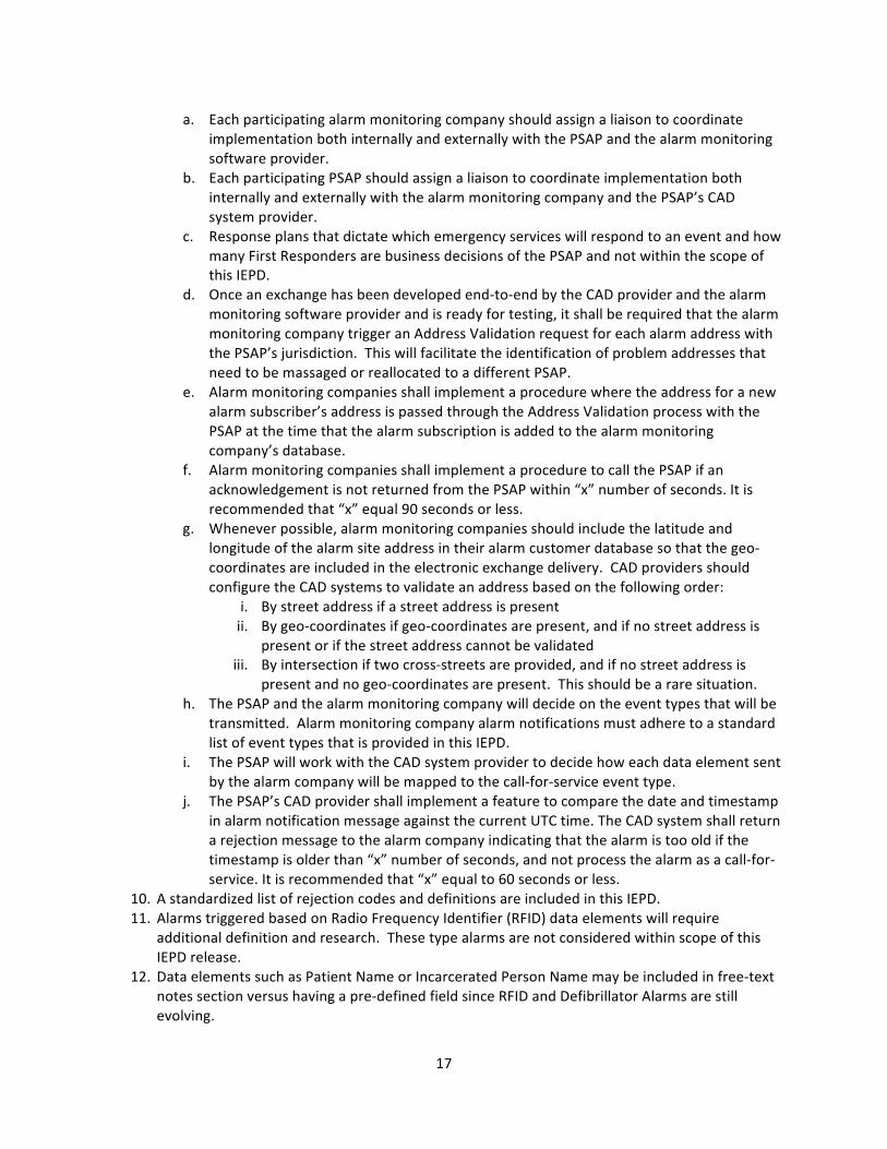
a. Each participating alarm monitoring company should assign a liaison to coordinate implementation both internally and externally with the PSAP and the alarm monitoring software provider.
b. Each participating PSAP should assign a liaison to coordinate implementation both internally and externally with the alarm monitoring company and the PSAP’s CAD system provider.
c. Response plans that dictate which emergency services will respond to an event and how many First Responders are business decisions of the PSAP and not within the scope of this IEPD.
d. Once an exchange has been developed end-‐to-‐end by the CAD provider and the alarm monitoring software provider and is ready for testing, it shall be required that the alarm monitoring company trigger an Address Validation request for each alarm address with the PSAP’s jurisdiction. This will facilitate the identification of problem addresses that need to be massaged or reallocated to a different PSAP.
e. Alarm monitoring companies shall implement a procedure where the address for a new alarm subscriber’s address is passed through the Address Validation process with the PSAP at the time that the alarm subscription is added to the alarm monitoring company’s database.
f. Alarm monitoring companies shall implement a procedure to call the PSAP if an acknowledgement is not returned from the PSAP within “x” number of seconds. It is recommended that “x” equal 90 seconds or less.
g. Whenever possible, alarm monitoring companies should include the latitude and longitude of the alarm site address in their alarm customer database so that the geo-‐coordinates are included in the electronic exchange delivery. CAD providers should configure the CAD systems to validate an address based on the following order:
i. By street address if a street address is present ii. By geo-‐coordinates if geo-‐coordinates are present, and if no street address is
present or if the street address cannot be validated iii. By intersection if two cross-‐streets are provided, and if no street address is
present and no geo-‐coordinates are present. This should be a rare situation. h. The PSAP and the alarm monitoring company will decide on the event types that will be
transmitted. Alarm monitoring company alarm notifications must adhere to a standard list of event types that is provided in this IEPD.
i. The PSAP will work with the CAD system provider to decide how each data element sent by the alarm company will be mapped to the call-‐for-‐service event type.
j. The PSAP’s CAD provider shall implement a feature to compare the date and timestamp in alarm notification message against the current UTC time. The CAD system shall return a rejection message to the alarm company indicating that the alarm is too old if the timestamp is older than “x” number of seconds, and not process the alarm as a call-‐for-‐service. It is recommended that “x” equal to 60 seconds or less.
10. A standardized list of rejection codes and definitions are included in this IEPD. 11. Alarms triggered based on Radio Frequency Identifier (RFID) data elements will require
additional definition and research. These type alarms are not considered within scope of this IEPD release.
12. Data elements such as Patient Name or Incarcerated Person Name may be included in free-‐text notes section versus having a pre-‐defined field since RFID and Defibrillator Alarms are still evolving.

18
13. (CRITICAL NOTE) Once the initial new alarm record is sent by the Alarm Monitoring Company, all subsequent Update transmissions to the PSAP must utilize the element name <StatusDescriptionText>. Most PSAPs do NOT want certain fields updated automatically by an external source such as an update to the address. Automatic updates to an address could trigger a different response plan. Instead, this IEPD has provided a single thread for all Updates to be sent to the CAD system. It is expected that the CAD System will add the Update to the call-‐for-‐service as an additional Comment or Note that will be seen by the radio operator. It shall be the radio operator’s responsibility to review each Comment sent as an Update message by the Alarm Monitoring Company and process the Update accordingly. Examples of an Update may include:
a. A Request to Cancel the Event b. An estimated time of arrival (ETA) for the key holder c. An individual on the premises of the alarm site who has been contacted but does not
know the proper pass code d. A change to one or more data elements originally sent as a component within the new
call event e. Other items of importance
14. While Telematics data transmission is not a primary purpose of this exchange, the exchange does include basic vehicle descriptor data elements to support vehicle alarm notifications by alarm monitoring central stations.

19
Supported Exchanges
Exchange Model
The Exchange Model diagram is located in the Supporting Documentation folder (“Exchange Model.jpg”).
FIGURE 3 -‐ EXTERNAL ALARM PROCESS MODEL

20
Case Scenario Samples
1 Exchange Medical Alert info
Examples of Triggering Events
• Allergic Reaction • Breathing Problem • Burn • Chest Pain / Heart Problem • Choking • Diabetic Problem • Fall • Seizure • Other Life Threatening Problems
Sample Scenario(s)
An elderly person living alone subscribes to an alarm monitoring service and wears a device that allows the individual to trigger a signal to the alarm company when experiencing a life-‐threatening medical problem. The individual begins to experience chest pains (or encounters any one of the triggering events listed above) and activates the device. The alarm monitoring company receives a notification signal that a Medical Alarm has been activated. The software application and the associated database utilized by the alarm monitoring company identifiers the proper 9-‐1-‐1 PSAP responsible for the dispatch of First Responder personnel to the premises’ address associated to the alarm. The alarm company operator initiates the electronic transmission of Medical Alert information to the correct 9-‐1-‐1 PSAP. Data transmitted to the 9-‐1-‐1 PSAP includes the alarm company’s event number, address of the alarm subscriber, the type of alarm, detailed information about the premises, and detailed information about the individual that will assist First Responders in locating the premises and be familiar with the patient’s history before their arrival. Upon receipt of this data, the 9-‐1-‐1 PSAP’s Computer-‐Aided Dispatch (CAD) System validates the address within the PSAP’s jurisdiction and creates a Call-‐for-‐Service. First Responders are immediately dispatched to the premises. Sensitive information about the individual typically will be sent to the First Responders’ mobile data computer (MDC). The CAD System transmits an electronic acknowledgement to the alarm company that references the alarm company’s event number and includes the PSAP’s event number(s) and an indication that the Call-‐for-‐Service has been sent to the dispatch queue to be dispatched to Emergency First Responders. Additional information relating to the event may be originated by the alarm company or the PSAP and transmitted to the other entity electronically.
Sample Business Rule(s)
• Depending on governing laws of the jurisdiction affected, the alarm company may attempt to reach someone at the premises before initiating the electronic exchange.
• If an address cannot be validated and Latitude/Longitude coordinates are present in the data exchange, the CAD System will attempt to validate using geo-‐coordinates.
• If the address and geo-‐coordinates (if present) cannot be validated, an electronic Rejection message will be returned by the PSAP to the alarm company. The alarm company operator is expected to take action according to alarm company procedures.
• First Responders dispatched may include EMS plus a combination of Fire and/or Law Enforcement depending on local PSAP agency procedures,
• Sensitive information about the individual typically may be sent to the First Responders’ mobile data computer (MDC).

21
2 Exchange Fire Alarm info
Examples of Triggering Events
• Smoke / Heat Detector • Manual Pull Station • Sprinkler/Waterflow Detector
Sample Scenario(s)
A fire begins inside a structure and is spotted by an individual. The individual pulls the manual pull station to summon the fire department and sound an alarm for others to evacuate. A signal is transmitted to the alarm company.
A fire begins inside a structure and causes the sprinkler system to activate. A sprinkler/waterflow activation signal is transmitted to the alarm company.
A fire begins inside a structure and is sensed by a smoke or heat detector. A signal is transmitted to the alarm company.
An alarm monitoring service receives a signal that a Fire Alarm has been activated via one of the trigger examples above. The software application and the associated database utilized by the alarm monitoring company identifies the proper 9-‐1-‐1 PSAP responsible for the dispatch of First Responder personnel to the premises’ address associated to the alarm. The alarm company operator initiates the electronic transmission of Fire Alarm information to the correct 9-‐1-‐1 PSAP. Data transmitted to the 9-‐1-‐1 PSAP includes the alarm company’s event number, address of the alarm subscriber, the type of alarm including the triggering method, and detailed information about the premises including commercial versus residential, detailed directions, hazardous materials stored at the facility, etc, that will assist First Responders in locating the premises and be familiar with any dangers that could be presented to the First Responders upon their arrival. Upon receipt of this data, the 9-‐1-‐1 PSAP’s Computer-‐Aided Dispatch (CAD) System validates the address within the PSAP’s jurisdiction and creates a Call-‐for-‐Service. First Responders are immediately dispatched to the premises. The CAD System transmits an electronic acknowledgement to the alarm company that references the alarm company’s event number and includes the PSAP’s event number(s) and an indication that the Call-‐for-‐Service has been sent to the dispatch queue to be dispatched to Emergency First Responders. Additional information relating to the event may be originated by the alarm company or the PSAP and transmitted to the other entity electronically. A notification from CAD to Traffic web sites and Intelligent Transportation Systems could be sent when the amount of responding fire apparatus is significant and traffic in the area of the emergency could be affected.
Sample Business Rule(s)
• Depending on governing laws of the jurisdiction affected, the alarm company may attempt to reach someone at the premises if the premises type is RESIDENTIAL before initiating the electronic exchange.
• If an address cannot be validated and Latitude/Longitude coordinates are present in the data exchange, the CAD System will attempt to validate using geo-‐coordinates.
• If the address and geo-‐coordinates (if present) cannot be validated, an electronic Rejection message will be returned by the PSAP to the alarm company. The alarm company operator is expected to take action according to alarm company procedures.
• First Responders dispatched may include Fire plus a combination of EMS and/or Law Enforcement depending on local PSAP agency procedures, Law enforcement could be typically dispatched for traffic and crowd control purposes.
22
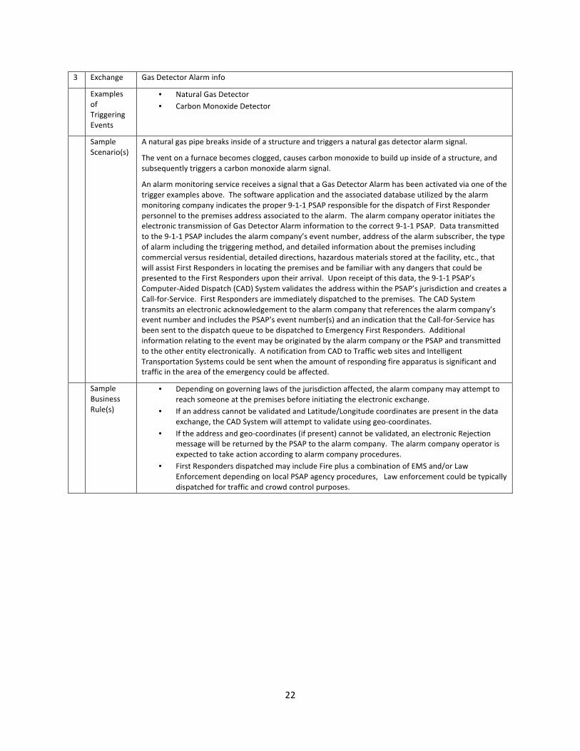
3 Exchange Gas Detector Alarm info
Examples of Triggering Events
• Natural Gas Detector • Carbon Monoxide Detector
Sample Scenario(s)
A natural gas pipe breaks inside of a structure and triggers a natural gas detector alarm signal.
The vent on a furnace becomes clogged, causes carbon monoxide to build up inside of a structure, and subsequently triggers a carbon monoxide alarm signal.
An alarm monitoring service receives a signal that a Gas Detector Alarm has been activated via one of the trigger examples above. The software application and the associated database utilized by the alarm monitoring company indicates the proper 9-‐1-‐1 PSAP responsible for the dispatch of First Responder personnel to the premises address associated to the alarm. The alarm company operator initiates the electronic transmission of Gas Detector Alarm information to the correct 9-‐1-‐1 PSAP. Data transmitted to the 9-‐1-‐1 PSAP includes the alarm company’s event number, address of the alarm subscriber, the type of alarm including the triggering method, and detailed information about the premises including commercial versus residential, detailed directions, hazardous materials stored at the facility, etc., that will assist First Responders in locating the premises and be familiar with any dangers that could be presented to the First Responders upon their arrival. Upon receipt of this data, the 9-‐1-‐1 PSAP’s Computer-‐Aided Dispatch (CAD) System validates the address within the PSAP’s jurisdiction and creates a Call-‐for-‐Service. First Responders are immediately dispatched to the premises. The CAD System transmits an electronic acknowledgement to the alarm company that references the alarm company’s event number and includes the PSAP’s event number(s) and an indication that the Call-‐for-‐Service has been sent to the dispatch queue to be dispatched to Emergency First Responders. Additional information relating to the event may be originated by the alarm company or the PSAP and transmitted to the other entity electronically. A notification from CAD to Traffic web sites and Intelligent Transportation Systems could be sent when the amount of responding fire apparatus is significant and traffic in the area of the emergency could be affected.
Sample Business Rule(s)
• Depending on governing laws of the jurisdiction affected, the alarm company may attempt to reach someone at the premises before initiating the electronic exchange.
• If an address cannot be validated and Latitude/Longitude coordinates are present in the data exchange, the CAD System will attempt to validate using geo-‐coordinates.
• If the address and geo-‐coordinates (if present) cannot be validated, an electronic Rejection message will be returned by the PSAP to the alarm company. The alarm company operator is expected to take action according to alarm company procedures.
• First Responders dispatched may include Fire plus a combination of EMS and/or Law Enforcement depending on local PSAP agency procedures, Law enforcement could be typically dispatched for traffic and crowd control purposes.

23
4 Exchange Burglar Alarm info
Examples of Triggering Events
• Burglar Alarm • Tamper Alarm (Someone tampering with equipment) • Restore Signal (Alarm Restored but no prior alarm received) • Phone Line Failure (Someone has possibly cut phone line) • Open / Close Signal (Someone disarming system without permission) • Reset / Cancel (Someone disarming system without permission)
Sample Scenario(s)
A residence is broken into and the suspect’s movement is detected by a motion detector.
Someone is attempting to disable the premises alarm equipment.
The alarm company receives an alarm restore message but no prior alarm was received.
Someone attempts to cut the telephone line.
Someone attempts to disarm the alarm system without the proper security code.
An alarm monitoring service receives a signal that an alarm has been activated via one of the trigger examples above. The software application and the associated database utilized by the alarm monitoring company indicates the proper 9-‐1-‐1 PSAP responsible for the dispatch of Law Enforcement First Responder personnel to the premises address associated to the alarm. The alarm company operator initiates the electronic transmission of Burglar Alarm information to the correct 9-‐1-‐1 PSAP. Data transmitted to the 9-‐1-‐1 PSAP includes the alarm company’s event number, address of the alarm subscriber, the type of alarm including the triggering method (motion detector, glass breakage, etc) and specific location of the triggering device (rear door, front hall, etc), and detailed information about the premises including commercial versus residential, detailed directions, hazardous materials stored at the facility, etc, that will assist Law Enforcement First Responders in locating the premises and be familiar with any dangers that could be presented to the First Responders upon their arrival. Upon receipt of this data, the 9-‐1-‐1 PSAP’s Computer-‐Aided Dispatch (CAD) System validates the address within the PSAP’s jurisdiction and creates a Call-‐for-‐Service. Law Enforcement First Responders are immediately dispatched to the premises. The CAD System transmits an electronic acknowledgement to the alarm company that references the alarm company’s event number and includes the PSAP’s event number(s) and an indication that the Call-‐for-‐Service has been sent to the dispatch queue to be dispatched to Law Enforcement First Responders. Additional information relating to the event may be originated by the alarm company or the PSAP and transmitted to the other entity electronically. Additional information may consist of a cancellation request from the alarm company, information about the key-‐holder from the alarm company, status changes by responding Law Enforcement officers, and situation found information as denoted by the Law Enforcement Officer(s) on scene.
Sample Business Rule(s)
• Depending on governing laws of the jurisdiction affected, the alarm company may attempt to reach someone at the premises before initiating the electronic exchange.
• If an address cannot be validated and Latitude/Longitude coordinates are present in the data exchange, the CAD System will attempt to validate using geo-‐coordinates.
• If the address and geo-‐coordinates (if present) cannot be validated, an electronic Rejection message will be returned by the PSAP to the alarm company. The alarm company operator is expected to take action according to alarm company procedures.

24
5 Exchange Hold-‐up/Panic/Duress Alarm (Robbery in progress) info
Examples of Triggering Events
• Hold-‐up Alarm • Panic / Duress Alarm
Sample Scenario(s)
A jewelry store is being robbed and a store employee manages to trigger a push button signaling device to initiate a Hold-‐up alarm.
A home invasion occurs and the homeowner manages to trigger a signaling device to initiate a Panic / Duress alarm.
An alarm monitoring service receives a signal that an alarm has been activated via one of the trigger examples above. The software application and the associated database utilized by the alarm monitoring company indicates the proper 9-‐1-‐1 PSAP responsible for the dispatch of Law Enforcement First Responder personnel to the premises address associated to the alarm. The alarm company operator initiates the electronic transmission of alarm information to the correct 9-‐1-‐1 PSAP. Data transmitted to the 9-‐1-‐1 PSAP includes the alarm company’s event number, address of the alarm subscriber, the type of alarm, and detailed information about the premises including commercial versus residential, detailed directions, hazardous materials stored at the facility, etc, that will assist Law Enforcement First Responders in locating the premises and be familiar with any dangers that could be presented to the First Responders upon their arrival. Upon receipt of this data, the 9-‐1-‐1 PSAP’s Computer-‐Aided Dispatch (CAD) System validates the address within the PSAP’s jurisdiction and creates a Call-‐for-‐Service. Law Enforcement First Responders are immediately dispatched to the premises. The CAD System transmits an electronic acknowledgement to the alarm company that references the alarm company’s event number and includes the PSAP’s event number(s) and an indication that the Call-‐for-‐Service has been sent to the dispatch queue to be dispatched to Law Enforcement First Responders. Additional information relating to the event may be originated by the alarm company or the PSAP and transmitted to the other entity electronically. Additional information may consist of a cancellation request from the alarm company, additional details concerning the event from the alarm company, status changes by responding Law Enforcement officers, and situation found information as denoted by the Law Enforcement Officer(s) on scene.
Sample Business Rule(s)
• Depending on governing laws of the jurisdiction affected, the alarm company may attempt to reach someone at the premises before initiating the electronic exchange.
• If an address cannot be validated and Latitude/Longitude coordinates are present in the data exchange, the CAD System will attempt to validate using geo-‐coordinates.
• If the address and geo-‐coordinates (if present) cannot be validated, an electronic Rejection message will be returned by the PSAP to the alarm company. The alarm company operator is expected to take action according to alarm company procedures.
• PSAPs generally will treat an alarm notification as a “Hold-‐up” Alarm if the premises type is Commercial. Otherwise the event type is generally treated as a “Panic / Duress” alarm when the premises type is residential.
25
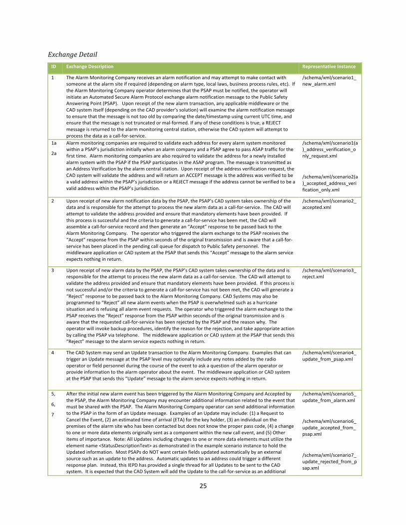
Exchange Detail ID Exchange Description Representative Instance
1 The Alarm Monitoring Company receives an alarm notification and may attempt to make contact with someone at the alarm site if required (depending on alarm type, local laws, business process rules, etc). If the Alarm Monitoring Company operator determines that the PSAP must be notified, the operator will initiate an Automated Secure Alarm Protocol exchange alarm notification message to the Public Safety Answering Point (PSAP). Upon receipt of the new alarm transaction, any applicable middleware or the CAD system itself (depending on the CAD provider’s solution) will examine the alarm notification message to ensure that the message is not too old by comparing the date/timestamp using current UTC time, and ensure that the message is not truncated or mal-‐formed. If any of these conditions is true, a REJECT message is returned to the alarm monitoring central station, otherwise the CAD system will attempt to process the data as a call-‐for-‐service.
/schema/xml/scenario1_new_alarm.xml
1a
2a
Alarm monitoring companies are required to validate each address for every alarm system monitored within a PSAP’s jurisdiction initially when an alarm company and a PSAP agree to pass ASAP traffic for the first time. Alarm monitoring companies are also required to validate the address for a newly installed alarm system with the PSAP if the PSAP participates in the ASAP program. The message is transmitted as an Address Verification by the alarm central station. Upon receipt of the address verification request, the CAD system will validate the address and will return an ACCEPT message is the address was verified to be a valid address within the PSAP’s jurisdiction or a REJECT message if the address cannot be verified to be a valid address within the PSAP’s jurisdiction.
/schema/xml/scenario1(a)_address_verification_only_request.xml
/schema/xml/scenario2(a)_accepted_address_verification_only.xml
2 Upon receipt of new alarm notification data by the PSAP, the PSAP’s CAD system takes ownership of the data and is responsible for the attempt to process the new alarm data as a call-‐for-‐service. The CAD will attempt to validate the address provided and ensure that mandatory elements have been provided. If this process is successful and the criteria to generate a call-‐for-‐service has been met, the CAD will assemble a call-‐for-‐service record and then generate an “Accept” response to be passed back to the Alarm Monitoring Company. The operator who triggered the alarm exchange to the PSAP receives the “Accept” response from the PSAP within seconds of the original transmission and is aware that a call-‐for-‐service has been placed in the pending call queue for dispatch to Public Safety personnel. The middleware application or CAD system at the PSAP that sends this “Accept” message to the alarm service expects nothing in return.
/schema/xml/scenario2_accepted.xml
3 Upon receipt of new alarm data by the PSAP, the PSAP’s CAD system takes ownership of the data and is responsible for the attempt to process the new alarm data as a call-‐for-‐service. The CAD will attempt to validate the address provided and ensure that mandatory elements have been provided. If this process is not successful and/or the criteria to generate a call-‐for-‐service has not been met, the CAD will generate a “Reject” response to be passed back to the Alarm Monitoring Company. CAD Systems may also be programmed to “Reject” all new alarm events when the PSAP is overwhelmed such as a hurricane situation and is refusing all alarm event requests. The operator who triggered the alarm exchange to the PSAP receives the “Reject” response from the PSAP within seconds of the original transmission and is aware that the requested call-‐for-‐service has been rejected by the PSAP and the reason why. The operator will invoke backup procedures, identify the reason for the rejection, and take appropriate action by calling the PSAP via telephone. The middleware application or CAD system at the PSAP that sends this “Reject” message to the alarm service expects nothing in return.
/schema/xml/scenario3_reject.xml
4 The CAD System may send an Update transaction to the Alarm Monitoring Company. Examples that can trigger an Update message at the PSAP level may optionally include any notes added by the radio operator or field personnel during the course of the event to ask a question of the alarm operator or provide information to the alarm operator about the event. The middleware application or CAD system at the PSAP that sends this “Update” message to the alarm service expects nothing in return.
/schema/xml/scenario4_update_from_psap.xml
5,
6,
7
After the initial new alarm event has been triggered by the Alarm Monitoring Company and Accepted by the PSAP, the Alarm Monitoring Company may encounter additional information related to the event that must be shared with the PSAP. The Alarm Monitoring Company operator can send additional information to the PSAP in the form of an Update message. Examples of an Update may include: (1) a Request to Cancel the Event, (2) an estimated time of arrival (ETA) for the key holder, (3) an individual on the premises of the alarm site who has been contacted but does not know the proper pass code, (4) a change to one or more data elements originally sent as a component within the new call event, and (5) Other items of importance. Note: All Updates including changes to one or more data elements must utilize the element name <StatusDescriptionText> as demonstrated in the example scenario instance to hold the Updated information. Most PSAPs do NOT want certain fields updated automatically by an external source such as an update to the address. Automatic updates to an address could trigger a different response plan. Instead, this IEPD has provided a single thread for all Updates to be sent to the CAD system. It is expected that the CAD System will add the Update to the call-‐for-‐service as an additional
/schema/xml/scenario5_update_from_alarm.xml
/schema/xml/scenario6_update_accepted_from_psap.xml
/schema/xml/scenario7_update_rejected_from_psap.xml
26
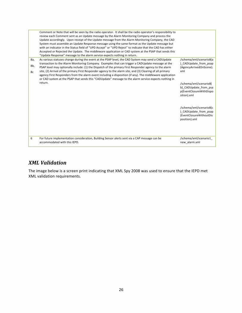
Comment or Note that will be seen by the radio operator. It shall be the radio operator’s responsibility to review each Comment sent as an Update message by the Alarm Monitoring Company and process the Update accordingly. Upon receipt of the Update message from the Alarm Monitoring Company, the CAD System must assemble an Update Response message using the same format as the Update message but with an indicator in the Status field of “UPD Accept” or “UPD Reject” to indicate that the CAD has either Accepted or Rejected the Update. The middleware application or CAD system at the PSAP that sends this “Update Response” message to the alarm service expects nothing in return.
8a,
8b,
8c
As various statuses change during the event at the PSAP level, the CAD System may send a CADUpdate transaction to the Alarm Monitoring Company. Examples that can trigger a CADUpdate message at the PSAP level may optionally include: (1) the Dispatch of the primary First Responder agency to the alarm site, (2) Arrival of the primary First Responder agency to the alarm site, and (3) Clearing of all primary agency First Responders from the alarm event including a disposition (if any). The middleware application or CAD system at the PSAP that sends this “CADUpdate” message to the alarm service expects nothing in return.
/schema/xml/scenario8(a)_CADUpdate_from_psap(AgencyArrivedOnScene).xml
/schema/xml/scenario8(b)_CADUpdate_from_psap(EventClosureWithDisposition).xml
/schema/xml/scenario8(c)_CADUpdate_from_psap(EventClosureWithoutDisposition).xml
6 For future implementation consideration, Building Sensor alerts sent via a CAP message can be accommodated with this IEPD.
/schema/xml/scenario1_new_alarm.xml
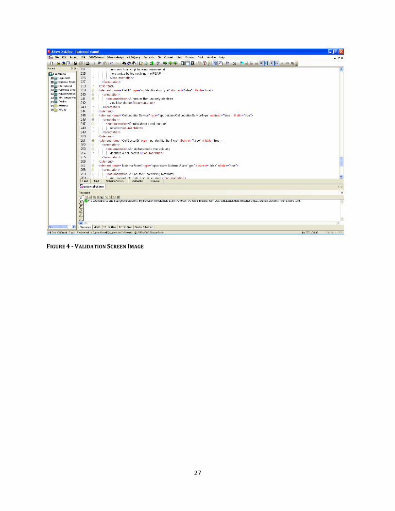
XML Validation The image below is a screen print indicating that XML Spy 2008 was used to ensure that the IEPD met XML validation requirements.
27
FIGURE 4 -‐ VALIDATION SCREEN IMAGE

28
GLOSSARY
APCO ......... Association of Public Safety Communications Officials International
BJA ............ Bureau of Justice Assistance
CAD ........... Computer-‐Aided Dispatch
CMT ........... Component Mapping Spreadsheet
CSAA .......... Central Station Alarm Association
DMZ .......... a demilitarized zone (DMZ), based on military usage of the term but more appropriately known as a demarcation zone or perimeter network, is a physical or logical sub-‐network that contains and exposes an organization's external services to a larger, untrusted network, usually the Internet. The purpose of a DMZ is to add an additional layer of security to an organization's Local Area Network (LAN); an external attacker only has access to equipment in the DMZ, rather than the whole of the network
DOJ ............ Department Of Justice
EMS ........... Emergency Medical Services
ETA ............ Estimated Time of Arrival
GJXDM ...... Global Justice Xml Data Model
IEPD ........... Information Exchange Package Documentation
IJIS ............. IJIS Institute
MDC .......... Mobile Data Computer
NENA ......... National Emergency Number Association
NIEM ......... National Information Exchange Model
Nlets .......... International Justice and Public Safety Network
PSAP .......... Public Safety Answering Point
PSDI ........... Public Safety Data Interoperability project
RFID ........... Radio Frequency IDentification
SME ........... Subject Matter Expert
XML ........... eXtensible Markup Language
XSL ............. Extensible Stylesheet Language (a technical artifact within the IEPD)

Alarm Monitoring Company to PSAP CAD Automated Secure Alarm Protocol (ASAP)
APCO/CSAA ANS 2.101.2-‐2014
Notes

351 N. Williamson Blvd. Daytona Beach, FL 32114 USA
www.apcointl.org
Related Documents