arXiv:1109.1127v1 [cond-mat.mes-hall] 6 Sep 2011 Anisotropic magnetic deflagration in single crystals of Gd 5 Ge 4 S. V´ elez, 1,2, ∗ J. M. Hernandez, 1, 2 A. Garc´ ıa-Santiago, 1,2 J. Tejada, 1, 2 V. K. Pecharsky, 3, 4 K. A. Gschneidner, Jr., 3, 4 D. L. Schlagel, 3 T. A. Lograsso, 3 and P. V. Santos 5 1 Grup de Magnetisme, Departament de F´ ısica Fonamental, Facultat de F´ ısica, Universitat de Barcelona, c. Mart´ ı i Franqu` es 1, planta 4, edifici nou, 08028 Barcelona, Spain 2 Institut de Nanoci` encia i Nanotecnologia IN 2 UB, Universitat de Barcelona, c. Mart´ ı i Franqu` es 1, 08028 Barcelona, Spain 3 The Ames Laboratory, U.S. Department of Energy, Iowa State University, Ames, Iowa 50011-3020, USA 4 Department of Materials Science and Engineering, Iowa State University, Ames, Iowa 50011-2300, USA 5 Paul-Drude-Institut f¨ ur Festk¨ orperelektronik, Hausvogteiplatz 5-7, 10117 Berlin, Germany (Dated: September 7, 2011) Experimental evidence of the anisotropy of the magnetic deflagration associated with the low- temperature first order antiferromagnetic (AFM) → ferromagnetic (FM) phase-transition in single crystals of Gd5Ge4 is reported. The deflagrations have been induced by controlled pulses of surface acoustic waves (SAW) allowing us to explore both the magnetic field and temperature dependencies on the characteristic times of the phenomenon. The study was done using samples with different geometries and configurations between the SAW pulses and the direction of the applied magnetic field with respect to the three main crystallographic directions of the samples. The effect of temperature is nearly negligible, whereas observed strong magnetic field dependence correlates with the magnetic anisotropy of the sample. Finally, the role of the SAW pulses in both the ignition and formation of the deflagration front was also studied, and we show that the thermal diffusivity of Gd5Ge4 must be anisotropic, following κa >κ b >κc . PACS numbers: 75.60.Jk, 75.30.Kz, 82.33.Vx I. INTRODUCTION The Gd 5 Ge 4 intermetallic compound, together with other Si doped Gd 5 (Si x Ge 1−x ) 4 alloys, has attracted con- siderable attention over the last few years, principally due to their unusual giant magnetocaloric properties 1–4 . This effect is associated with a first-order AFM↔FM phase transition that occurs simultaneously with a structural transformation 5,6 . The rich phenomenology of these transitions in Gd 5 Ge 4 has been broadly studied as a func- tion of temperature and magnetic field using both poly- crystalline and single crystalline samples 7–13 . At temper- atures exceeding T ∼ 20 K, the isothermal field-driven AFM↔FM transitions can be continuously reproduced but, when the sample is cooled below T ∼ 10 K at zero magnetic field, the field-driven AFM→FM transition be- comes irreversible. Several reported magnetic behaviors, such as the glassy properties 14,15 , have suggested that the magnetocrystallographic ground state of this system at zero magnetic field could be the FM O(I) [O(I) is a common notation of the low-volume orthorhombic poly- morph of Gd 5 Ge 4 , see Ref. 16 for details], whereas the initial AFM O(II) state [the O(II) is a common notation of the high-volume orthorhombic polymorph of Gd 5 Ge 4 ], which is stable in a zero field cooled (ZFC) process, is due to the kinetic arrest of the O(II) crystal structure. However, recent first principles modeling 17–19 of the free energy of the different O(I) and O(II) magnetic phases, have pointed out that the ground state of this crystal must be the AFM O(II). At low temperatures, the first order field-driven AFM→FM phase transition can proceed in two different fashions. Usually, this transition is rather gradual and takes place over a wide range of magnetic fields, but when the sample is large enough or the magnetic field is swept at high rates, this phase transformation is abrupt, which can be identified in the M −H cycle as a magnetic jump 6 . Historically, such magnetic discontinuities have been called magnetic avalanches and they have been also ob- served in other materials 20–27 which also exhibit a giant magnetocaloric effect 23,28 related to a transition from a kinetically-arrested state to the magnetic equilibrium 4,29 . The dynamics of the magnetization of the sample dur- ing such transitions have been reported first in molecular magnets 30–38 , and later in manganites 39–41 and polycrys- talline samples of Gd 5 Ge 4 42 . For all of these materials, it was found that a phase-transition front is formed and propagates through the sample at a constant speed on the order of a few m/s. The strong similarities between this magnetic phenomenon and a chemical combustion 43 have lead the scientific community to call it magnetic deflagration. In magnetic deflagration, the role of fuel is played by the energy difference between the metastable and the sta- ble states of the system, namely ΔE. This energy differ- ence is related to the intrinsic energy of the metastable ordered magnetic phase plus the Zeeman energy, that comes from the interaction of an external magnetic field H with the spins in the system. On the other hand, the rate of heat transferred from the region of burning spins to their flammable neighbors is controlled by i) the energy

Welcome message from author
This document is posted to help you gain knowledge. Please leave a comment to let me know what you think about it! Share it to your friends and learn new things together.
Transcript
arX
iv:1
109.
1127
v1 [
cond
-mat
.mes
-hal
l] 6
Sep
201
1
Anisotropic magnetic deflagration in single crystals of Gd5Ge4
S. Velez,1, 2, ∗ J. M. Hernandez,1, 2 A. Garcıa-Santiago,1,2 J. Tejada,1, 2 V. K. Pecharsky,3,4
K. A. Gschneidner, Jr.,3, 4 D. L. Schlagel,3 T. A. Lograsso,3 and P. V. Santos5
1Grup de Magnetisme, Departament de Fısica Fonamental, Facultat de Fısica,
Universitat de Barcelona, c. Martı i Franques 1, planta 4, edifici nou, 08028 Barcelona, Spain2Institut de Nanociencia i Nanotecnologia IN2UB,
Universitat de Barcelona, c. Martı i Franques 1, 08028 Barcelona, Spain3The Ames Laboratory, U.S. Department of Energy,
Iowa State University, Ames, Iowa 50011-3020, USA4Department of Materials Science and Engineering,
Iowa State University, Ames, Iowa 50011-2300, USA5Paul-Drude-Institut fur Festkorperelektronik, Hausvogteiplatz 5-7, 10117 Berlin, Germany
(Dated: September 7, 2011)
Experimental evidence of the anisotropy of the magnetic deflagration associated with the low-temperature first order antiferromagnetic (AFM) → ferromagnetic (FM) phase-transition in singlecrystals of Gd5Ge4 is reported. The deflagrations have been induced by controlled pulses of surfaceacoustic waves (SAW) allowing us to explore both the magnetic field and temperature dependencieson the characteristic times of the phenomenon. The study was done using samples with differentgeometries and configurations between the SAW pulses and the direction of the applied magnetic fieldwith respect to the three main crystallographic directions of the samples. The effect of temperatureis nearly negligible, whereas observed strong magnetic field dependence correlates with the magneticanisotropy of the sample. Finally, the role of the SAW pulses in both the ignition and formation ofthe deflagration front was also studied, and we show that the thermal diffusivity of Gd5Ge4 mustbe anisotropic, following κa > κb > κc.
PACS numbers: 75.60.Jk, 75.30.Kz, 82.33.Vx
I. INTRODUCTION
The Gd5Ge4 intermetallic compound, together withother Si doped Gd5(SixGe1−x)4 alloys, has attracted con-siderable attention over the last few years, principally dueto their unusual giant magnetocaloric properties1–4. Thiseffect is associated with a first-order AFM↔FM phasetransition that occurs simultaneously with a structuraltransformation5,6. The rich phenomenology of thesetransitions in Gd5Ge4 has been broadly studied as a func-tion of temperature and magnetic field using both poly-crystalline and single crystalline samples7–13. At temper-atures exceeding T ∼ 20 K, the isothermal field-drivenAFM↔FM transitions can be continuously reproducedbut, when the sample is cooled below T ∼ 10 K at zeromagnetic field, the field-driven AFM→FM transition be-comes irreversible. Several reported magnetic behaviors,such as the glassy properties14,15, have suggested thatthe magnetocrystallographic ground state of this systemat zero magnetic field could be the FM O(I) [O(I) is acommon notation of the low-volume orthorhombic poly-morph of Gd5Ge4, see Ref. 16 for details], whereas theinitial AFM O(II) state [the O(II) is a common notationof the high-volume orthorhombic polymorph of Gd5Ge4],which is stable in a zero field cooled (ZFC) process, isdue to the kinetic arrest of the O(II) crystal structure.However, recent first principles modeling17–19 of the freeenergy of the different O(I) and O(II) magnetic phases,have pointed out that the ground state of this crystalmust be the AFM O(II).
At low temperatures, the first order field-drivenAFM→FM phase transition can proceed in two differentfashions. Usually, this transition is rather gradual andtakes place over a wide range of magnetic fields, but whenthe sample is large enough or the magnetic field is sweptat high rates, this phase transformation is abrupt, whichcan be identified in the M−H cycle as a magnetic jump6.Historically, such magnetic discontinuities have beencalled magnetic avalanches and they have been also ob-served in other materials20–27 which also exhibit a giantmagnetocaloric effect23,28 related to a transition from akinetically-arrested state to the magnetic equilibrium4,29.The dynamics of the magnetization of the sample dur-ing such transitions have been reported first in molecularmagnets30–38, and later in manganites39–41 and polycrys-talline samples of Gd5Ge4
42. For all of these materials,it was found that a phase-transition front is formed andpropagates through the sample at a constant speed onthe order of a few m/s. The strong similarities betweenthis magnetic phenomenon and a chemical combustion43
have lead the scientific community to call it magnetic
deflagration.In magnetic deflagration, the role of fuel is played by
the energy difference between the metastable and the sta-ble states of the system, namely ∆E. This energy differ-ence is related to the intrinsic energy of the metastableordered magnetic phase plus the Zeeman energy, thatcomes from the interaction of an external magnetic fieldH with the spins in the system. On the other hand, therate of heat transferred from the region of burning spinsto their flammable neighbors is controlled by i) the energy
2
barrier to be overcome by the metastable spins, U ; ii) theso-called characteristic time attempt τ0; iii) the thermaldiffusivity κ; and iv) the fraction of flammable spins nm.The main difference between chemical combustion andmagnetic deflagration is that for the latter the source ofenergy is the reordering of the spins of the system insteadof an irreversible chemical reaction. Therefore, magneticdeflagration becomes of special interest due to the non-destructive character of the process that allows complexphenomena of deflagration to be explored under differentconditions.The theory of magnetic deflagration44 determines the
instability condition that leads a typical broad transi-tion to the occurrence of a deflagration process. Whenthe rate of the thermal jump over the energy barrier fora single metastable spin, Γ, exceeds some critical value,Γc, the nucleation of the deflagration front and the sub-sequent thermal runaway should take place. This criticalrate can be written as
Γc =8k(T )kBT
2
U(H)∆E(H)nml2, (1)
where l is some characteristic length, k(T ) = κ(T )C(T )is the thermal conductivity, and C(T ) is the specific heat.The front of propagation is identified as the flame of the
process, whose characteristic size is δ ∼ [κ(Tf )/Γ(Tf )]1/2
,where Tf is the corresponding temperature of the flame,which is given by
Tf =ΘD
π
[5nm∆E(H)
3kBΘD
]1/4
, (2)
where ΘD is the Debye temperature. Finally, in the ap-proximation of a planar burning-front, the speed of theflame is
v(H) =
[κ(Tf )
τ0·4kBTf(H)
U(H)
]1/2
exp
[−U(H)
2kBTf(H)
]
. (3)
Note that Eq. (1) can be used to establish the thresh-old condition for the occurrence of spontaneous magneticdeflagration in a field-sweep experiment30,33,36,37,39,42.However, in such experiment, it becomes a difficult taskto explore the field dependence of the speed of theflame, v(H). To solve that, experimentalists have de-veloped techniques to study the magnetic deflagrationusing controlled experimental conditions. These experi-ments consist, basically, of sending a heat pulse that actsas a spark of flame that ignites the deflagration. At-tached resistors32,34,35,38, electrical contacts made on thesample42 or surface acoustic waves (SAW)31,39 are exam-ples of sources that can be used for this purpose.However, the test of magnetic deflagration has been
limited to only a single law of propagation. In the caseof molecular magnets, the speed of the deflagration frontis determined by the value of the magnetic field appliedalong the easy magnetization axis, whereas the trans-verse field affects the threshold conditions [see for exam-ple ref. 37] via their unusual quantum properties45,46. In
the case of manganites, as well as polycrystalline samplesof Gd5Ge4, there is no influence, excluding geometricaleffects, of the direction of the applied magnetic field onthe properties of the deflagration process, whose observedcharacteristics are the result of averaging the propertiesalong the principal crystallographic axes of the sampledue to their random distribution. Therefore, the goal ofthis work is to investigate whether the magnetic defla-gration in single crystals of Gd5Ge4 is anisotropic, andwhat is the role of each crystallographic axis in both theformation and propagation of the deflagration front.
II. EXPERIMENTAL SET-UP
A large (approximately 4 mm diameter, 40 mm long)single crystal of Gd5Ge4 was grown using the tri-arctechnique47. The Gd metal used to prepare the sto-ichiometric polycrystalline charge weighing 20 g totalwas prepared by the Materials Preparation Center of theAmes Laboratory48, and it was at least 99.99 wt.% purewith respect to all other elements in the periodic table.The Ge was purchased from Meldform Metals, and itwas 99.999 wt.% pure. The as-grown single crystal wasoriented using backscatter Laue technique. Two differentsingle crystals of Gd5Ge4 used in this work were cut froma larger single crystal using spark erosion. Their dimen-sions were as follows: sample 1: S1 ≈ 1.17× 2.45× 1.04mm3 and sample 2: S2 ≈ 2.40 × 1.29 × 1.07 mm3 alongthe crystallographic directions a, b, and c, respectively.Figure 1 shows the schematic of the experimental set-
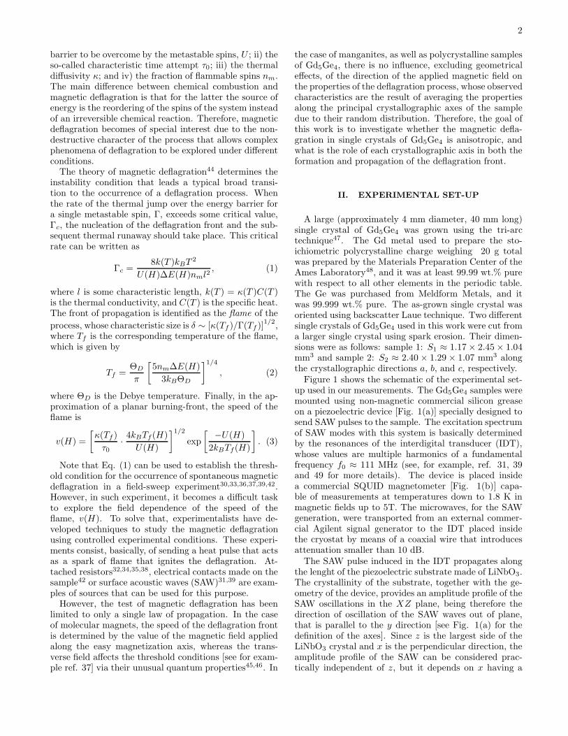
up used in our measurements. The Gd5Ge4 samples weremounted using non-magnetic commercial silicon greaseon a piezoelectric device [Fig. 1(a)] specially designed tosend SAW pulses to the sample. The excitation spectrumof SAW modes with this system is basically determinedby the resonances of the interdigital transducer (IDT),whose values are multiple harmonics of a fundamentalfrequency f0 ≈ 111 MHz (see, for example, ref. 31, 39and 49 for more details). The device is placed insidea commercial SQUID magnetometer [Fig. 1(b)] capa-ble of measurements at temperatures down to 1.8 K inmagnetic fields up to 5T. The microwaves, for the SAWgeneration, were transported from an external commer-cial Agilent signal generator to the IDT placed insidethe cryostat by means of a coaxial wire that introducesattenuation smaller than 10 dB.The SAW pulse induced in the IDT propagates along
the lenght of the piezoelectric substrate made of LiNbO3.The crystallinity of the substrate, together with the ge-ometry of the device, provides an amplitude profile of theSAW oscillations in the XZ plane, being therefore thedirection of oscillation of the SAW waves out of plane,that is parallel to the y direction [see Fig. 1(a) for thedefinition of the axes]. Since z is the largest side of theLiNbO3 crystal and x is the perpendicular direction, theamplitude profile of the SAW can be considered prac-tically independent of z, but it depends on x having a
3
maximum at x = 0 (that is, the position of the center ofthe IDT; see for example ref. 50, and references therein,for more details). When desirable experimental condi-tions (a specific combination of T and H) are reachedand stable, a controlled SAW pulse is delivered to ignitethe magnetic deflagration process in the Gd5Ge4 sample.
FIG. 1: Experimental set-up. (a) Schematic of the piezoelet-ric device used. 1, coaxial cable; 2, conducting stripes; 3, IDT;4, LiNbO3; 5, single crystalline sample of Gd5Ge4. (b) Viewof the spatial distribution of the piezoelectric set-up insidethe SQUID magnetometer. 1, coaxial cable; 2, piezoelectricset-up; 3, sample holder; 4, superconducting coils for the fieldgeneration; 5, magnetometer’s pick-up coils.
The magnetic field was always applied along the z di-rection of the sample holder [as shown in Fig. 1(b)], andthe piezoelectric set-up was placed between the pick-upcoils of the SQUID magnetometer. Two different tech-niques have been used to obtain magnetic measurementswith this system. The first, and the typical mode, con-sists of taking dc magnetic measurements by moving thesample through the four pick-up coils of the magnetome-ter. It allows one to obtain the absolute magnetic mo-ment of a given sample with a very high precision. Thistechnique has been used i) to characterize the magneticproperties of the sample and ii) to verify the magneticstate of the sample before and after each induced defla-gration. The limitation of this mode is the time it takes toperform each measurement, which is approximately ∼ 30seconds. The second method consists of directly mea-suring the voltage from the SQUID-voltmeter withoutrequiring any motion of the sample. Placing the centerof the sample at the position of the inner coils [as shownin Fig. 1(b)], where the sensitivity of the system has itsmaximum, the voltage drop recorded is directly related tothe magnetic state of the sample [i.e., ∆V ∝ ∆M ]. This
technique allows us to monitor fast magnetic changeswith a time-resolution better than 0.01 ms, so that wecan measure the time evolution of the magnetization ofthe sample during a magnetic deflagration process.Each single crystal has been studied under different
sample/set-up configurations to elucidate the role of eachcrystallographic axis on the properties of the deflagrationphenomenon. Due to geometrical restrictions, four differ-ent configurations were available to be explored for eachsample. When the magnetic field is applied along thelongest side of the crystal, the SAW pulse can be appliedto either of the two shorter sides. On the other hand, ifthe applied field is along one of the shorter directions, theSAW pulse can be applied parallel to the other short side.We will refer to each sample configuration using the fol-lowing notation: Si(x, y, z), where i denotes the samplenumber, and x, y and z, correspond to the orientation ofeach crystallographic axis of the sample with respect tothe coordinate system of the sample holder shown in Fig.1(a). For example, S2(a, b, c) refers to sample 2 with itsa-axis parallel to the x-direction of the sample holder, b-axis parallel to the y-direction, and c-axis parallel to thez-direction, which is the direction of the magnetic fieldvector.
III. RESULTS
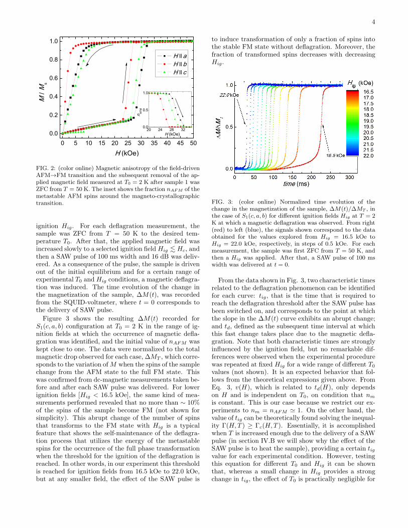
DC magnetic measurements of the field-drivenAFM→FM transition at low temperatures were carriedout for both Gd5Ge4 samples and for each configurationafter the sample was ZFC from T = 50 K. Figure 2 showsthe AFM→FM transformation and the subsequent re-moval of the magnetic field in the FM state obtainedat T = 2 K for each independent crystallographic axisof the system using sample 1. The same results wereobtained for sample 2 but these are not shown here forbrevity. As the magnetic field is increased from zero,the linear slope of the M(H) curves [note that the ob-served step around H ∼ 8 kOe when the magnetic fieldis applied along the c-axis is associated with the spin-floptransition8] suggest that the initial state of the sample ispurely AFM, and it remains unchanged, until direction-specific critical magnetic field, Hc, is reached, whose val-ues at T = 2 K are 28 kOe, 23 kOe and 26 kOe for thea, b and c crystallographic axis, respectively. Above it,the AFM→FM transformation is quite gradual, and ittakes place over a field range ∆H ∼ 4 kOe. The insetof Fig. 2 shows, specifically, the fraction nAFM (H) ofmetastable AFM spins around the transition. At highertemperatures, the critical field Hc(T ) decreases with therate of dHc/dT ≈ −1.5 kOe/K in the range 2− 8 K. Allof these results are in agreement with the previous datareported for single crystalline Gd5Ge4 samples11.After each crystallographic axis has been magnetically
characterized, we proceeded to perform the deflagrationexperiments. Two control variables were i) the initialtemperature T0 and ii) the applied magnetic field for the
4
0 5 10 15 20 25 30 35 40 45 500.0
0.2
0.4
0.6
0.8
1.0
H ll a H ll b H ll c
M /
Ms
H (kOe)
20 24 28 320.0
0.5
1.0
H (kOe)n A
FM
FIG. 2: (color online) Magnetic anisotropy of the field-drivenAFM→FM transition and the subsequent removal of the ap-plied magnetic field measured at T0 = 2 K after sample 1 wasZFC from T = 50 K. The inset shows the fraction nAFM of themetastable AFM spins around the magneto-crystallographictransition.
ignition Hig. For each deflagration measurement, thesample was ZFC from T = 50 K to the desired tem-perature T0. After that, the applied magnetic field wasincreased slowly to a selected ignition fieldHig . Hc, andthen a SAW pulse of 100 ms width and 16 dB was deliv-ered. As a consequence of the pulse, the sample is drivenout of the initial equilibrium and for a certain range ofexperimental T0 and Hig conditions, a magnetic deflagra-tion was induced. The time evolution of the change inthe magnetization of the sample, ∆M(t), was recordedfrom the SQUID-voltmeter, where t = 0 corresponds tothe delivery of SAW pulse.
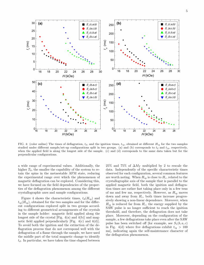
Figure 3 shows the resulting ∆M(t) recorded forS1(c, a, b) configuration at T0 = 2 K in the range of ig-nition fields at which the occurrence of magnetic defla-gration was identified, and the initial value of nAFM waskept close to one. The data were normalized to the totalmagnetic drop observed for each case, ∆MT , which corre-sponds to the variation ofM when the spins of the samplechange from the AFM state to the full FM state. Thiswas confirmed from dc-magnetic measurements taken be-fore and after each SAW pulse was delivered. For lowerignition fields [Hig < 16.5 kOe], the same kind of mea-surements performed revealed that no more than ∼ 10%of the spins of the sample become FM (not shown forsimplicity). This abrupt change of the number of spinsthat transforms to the FM state with Hig is a typicalfeature that shows the self-maintenance of the deflagra-tion process that utilizes the energy of the metastablespins for the occurrence of the full phase transformationwhen the threshold for the ignition of the deflagration isreached. In other words, in our experiment this thresholdis reached for ignition fields from 16.5 kOe to 22.0 kOe,but at any smaller field, the effect of the SAW pulse is
to induce transformation of only a fraction of spins intothe stable FM state without deflagration. Moreover, thefraction of transformed spins decreases with decreasingHig.
FIG. 3: (color online) Normalized time evolution of thechange in the magnetization of the sample, ∆M(t)/∆MT , inthe case of S1(c, a, b) for different ignition fields Hig at T = 2K at which a magnetic deflagration was observed. From right(red) to left (blue), the signals shown correspond to the dataobtained for the values explored from Hig = 16.5 kOe toHig = 22.0 kOe, respectively, in steps of 0.5 kOe. For eachmeasurement, the sample was first ZFC from T = 50 K, andthen a Hig was applied. After that, a SAW pulse of 100 mswidth was delivered at t = 0.
From the data shown in Fig. 3, two characteristic timesrelated to the deflagration phenomenon can be identifiedfor each curve: tig, that is the time that is required toreach the deflagration threshold after the SAW pulse hasbeen switched on, and corresponds to the point at whichthe slope in the ∆M(t) curve exhibits an abrupt change;and td, defined as the subsequent time interval at whichthis fast change takes place due to the magnetic defla-gration. Note that both characteristic times are stronglyinfluenced by the ignition field, but no remarkable dif-ferences were observed when the experimental procedurewas repeated at fixed Hig for a wide range of different T0
values (not shown). It is an expected behavior that fol-lows from the theoretical expressions given above. FromEq. 3, v(H), which is related to td(H), only dependson H and is independent on T0, on condition that nm
is constant. This is our case because we restrict our ex-periments to nm = nAFM ≃ 1. On the other hand, thevalue of tig can be theoretically found solving the inequal-ity Γ(H,T ) ≥ Γc(H,T ). Essentially, it is accomplishedwhen T is increased enough due to the delivery of a SAWpulse (in section IV.B we will show why the effect of theSAW pulse is to heat the sample), providing a certain tigvalue for each experimental condition. However, testingthis equation for different T0 and Hig it can be shownthat, whereas a small change in Hig provides a strongchange in tig, the effect of T0 is practically negligible for
5
16 18 20 22 24 26 28 300
5
10
15
20
25
30
16 18 20 22 24 26 28 300
50
100
150
200
250
16 18 20 22 24 26 280
10
20
30
40
50
16 18 20 22 24 26 280
50
100
150
200
250
S1 (c,a,b)
S1 (a,c,b)
S2 (c,b,a)
S2 (b,c,a)
t d (m
s)
H (kOe)
S1 (c,a,b)
S1 (a,c,b)
S2 (c,b,a)
S2 (b,c,a)
(a) (b)
t ig (
ms)
H (kOe)
S1 (b,a,c)
S2 (a,b,c)
S1 (b,c,a)
S2 (a,c,b)
(c)
t d (m
s)
H (kOe)
S1 (b,a,c)
S2 (a,b,c)
S1 (b,c,a)
S2 (a,c,b)
(d)
t ig (m
s)
H (kOe)
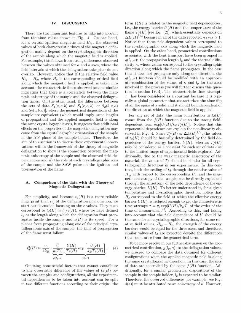
FIG. 4: (color online) The times of deflagration, td, and the ignition times, tig, obtained at different Hig for the two samplesstudied under different sample/set-up configurations split in two groups. (a) and (b) corresponds to td and tig , respectively,when the applied field is along the longest side of the sample. (c) and (d) corresponds to the same data taken but for theperpendicular configurations.
a wide range of experimental values. Additionally, thehigher T0, the smaller the capability of the system to re-tain the spins in the metaestable AFM state, reducingthe experimental range over which the phenomenon ofmagnetic deflagration can be explored. Considering this,we have focused on the field dependencies of the proper-ties of the deflagration phenomenon among the differentcrystallographic axes and sample configurations.
Figure 4 shows the characteristic times, td(Hig) andtig(Hig), obtained for the two samples and for the differ-ent configurations explored split in two groups accord-ing to different geometrical arrangements of the crystalsin the sample holder: magnetic field applied along thelongest side of the crystal [Fig. 4(a) and 4(b)] and mag-netic field applied perpendicularly [Fig. 4(c) and 4(d)].To avoid both the ignition and the extinction of the de-flagration process that do not correspond well with thedeflagration of a flame through the sample, we have usedthe middle part of the total magnetic change to identifytd. In particular, we have taken the time elapsed between
25% and 75% of ∆MT multiplied by 2 to rescale thedata. Independently of the specific characteristic timesobserved for each configuration, several common featuresare worth noting. When Hig is close to Hc, related to thecrystallographic axis of the sample that is parallel to theapplied magnetic field, both the ignition and deflagra-tion times are rather fast taking place only in a few tensof ms and few ms, respectively. However, as Hig movesdown and away from Hc, both times increase progres-sively showing a non-linear dependence. Moreover, whenHig is reduced far from Hc, the energy supplied by theSAW pulse is no longer sufficient to reach the ignitionthreshold, and therefore, the deflagration does not takeplace. Moreover, depending on the configuration of thesample, a few deflagrations take place even after the SAWpulse has been switched off [for example, see S1(b, a, c)in Fig. 4(d) where five deflagrations exhibit tig > 100ms], indicating again the self-maintenance character ofthe deflagration phenomenon.
6
IV. DISCUSSION
There are two important features to take into accountfrom the time values shown in Fig. 4. On one hand,for a certain ignition magnetic field Hig , the observedvalues of both characteristic times of the magnetic defla-gration mainly depend on the crystallographic directionof the sample along which the magnetic field is applied.For example, this follows from strong differences observedbetween the values obtained for a and b axes, where thefield intervals at which the deflagrations take place do notoverlap. However, notice that if the relative field valueHig − Hc, where Hc is the corresponding critical fieldalong which the magnetic field is applied, is taken intoaccount, the characteristic times observed become similarindicating that there is a correlation between the mag-netic anisotropy of the sample and the observed deflagra-tion times. On the other hand, the differences betweenthe sets of data S1(a, c, b) and S1(c, a, b) [or S2(b, c, a)and S2(c, b, a)], where the geometrical dispositions of thesample are equivalent (which would imply same lengthsof propagation) and the applied magnetic field is alongthe same crystallographic axis, it suggests that additionaleffects on the properties of the magnetic deflagration maycome from the crystallographic orientation of the samplein the XY plane of the sample holder. Therefore, theaim of this section is to discuss these experimental obser-vations within the framework of the theory of magneticdeflagration to show i) the connection between the mag-netic anisotropy of the sample and the observed field de-pendencies and ii) the role of each crystallographic axisof the sample and the SAW pulse on the ignition andpropagation of the flame.
A. Comparison of the data with the Theory of
Magnetic Deflagration
For simplicity, and because td(H) is a more reliablefingerprint than tig of the deflagration phenomenon, westart our discussion focusing on these values. They mustcorrespond to td(H) ≃ lp/v(H), where we have definedlp as the length along which the deflagration front prop-agates inside the sample and v(H) is its speed. For aplanar front propagating along one of the principal crys-tallographic axis of the sample, the time of propagationof the flame must follow:
t2d(H) ≈τ04kB
·l2p
κ(Tf )︸ ︷︷ ︸
g(lp,κ)
·U(H)
Tf(H)exp
[U(H)
kBTf (H)
]
︸ ︷︷ ︸
f(H)
. (4)
Omitting nonessential factors that cannot contributeto any observable difference of the values of td(H) be-tween the samples and configurations, all the experimen-tal dependencies to be taken into account can be splitin two different functions according to their origin: the
term f(H) is related to the magnetic field dependencies,i.e., the energy barrier U(H) and the temperature of theflame Tf (H) [see Eq. (2)], which essentially depends on
∆E(H)1/4 because in all of the data reported nAFM ≃ 1.Notice that these field-dependent values correspond tothe crystallographic axis along which the magnetic fieldis applied. On the other hand, geometrical contributionsassociated with the heat transport have been grouped ing(lp, κ): the propagation length lp and the thermal diffu-sivity κ, whose values correspond to the crystallographicdirection along which the flame propagates. In the casethat it does not propagate only along one direction, theg(lp, κ) function should be modified with an appropri-ate combination of the values of κ and lp for the axesinvolved in the process (we will further discuss this ques-tion in section IV.B). The characteristic time attempt,τ0, has been considered as a constant because it is typi-cally a global parameter that characterizes the time-flipof all the spins of a solid and it should be independent ofthe direction at which the magnetic field is applied.
For any set of data, the main contribution to td(H)comes from the f(H) function due to the strong field-dependent term exp[U(H)/kBTf (H)]. Notice that thisexponential dependence can explain the non-linearity ob-served in Fig. 4. Since Tf (H) ∝ ∆E(H)1/4, the valuesof td(H) should be basically determined by the field de-pendence of the energy barrier, U(H), whereas Tf (H)may be considered as a constant for each set of data dueto the limited range of experimental fields explored. Ad-ditionally, due to the weak magnetic anisotropy of thematerial, the values of Tf should be similar for all crys-tallographic directions in our experiments. In this con-text, both the scaling of td through the relative value ofHig with respect to the corresponding Hc, and the mag-netic anisotropy of the sample, can be directly explainedthrough the anisotropy of the field dependence of the en-ergy barrier, U(H). To better understand it, for a giventemperature and crystallographic direction, notice thatHc correspond to the field at which the effective energybarrier U(H), is reduced enough to get the characteristictime attempt τ = τ0 exp[U(H)/kBT ] of the order of thetime of measurement46. According to this, and takinginto account that the field dependence of U should bethe same for all crystallographic directions, for same rel-ative field values, Hig − Hc, the strength of the energybarriers would be equal for the three axes, and therefore,similar values of td are expected despite the differencesthat could arise from the geometrical term.
To be more precise in our further discussion on the geo-metrical contribution, g(lp, κ), to the deflagration values,we proceed to compare the data obtained for differentconfigurations when the applied magnetic field is alongthe same crystallographic direction. In this case, the setsof data are controlled by the same f(H) function. Ad-ditionally, for a similar geometrical dispositions of thesample in the sample holder, lp is expected to be similar.Therefore, the observed differences [for example, see Fig.4(a)] must be attributed to an anisotropy of κ. However,
7
to better understand this fact, we have to determine,first, what is the role of both the SAW pulse and sam-ple configuration on the nucleation of the deflagrationfront and, second, through which length(s)/direction(s)the deflagration front propagates. It could also give a rea-son for the different observed tig(Hig) values. However,before that, it is interesting to know whether the predic-tions of either the speed of the deflagration front or thevalues of the ignition time that arise from the theory ofmagnetic deflagration44 are in the range of the observedexperimental values.
From previously reported data42 of the magnetic de-flagration in a polycrystalline sample of Gd5Ge4, Tf wasestimated to be around 30 K. Taking into account thediscussion given above about the Tf (H) values of the dif-ferent crystallographic axis, and that the magnetic prop-erties of a polycrystal are averaged, we can assume thatTf ∼ 30 K is a good estimate of the temperature of theflame in all observed deflagrations. Thus, the thermal dif-fusivity of the sample is estimated to be51 κ(Tf ) ∼ 3·10−5
m2/s. Taking lp ∼ 1 mm, τ0 ∼ 10−7 s, and that in our ex-perimental field range U(H) should be around 200− 300K, one gets from Eq. (4), td ∼ 10 ms, which is in agood agreement with our observations. The other in-teresting parameter to test is the width of the flame δ,
which can be found through δ ∼ [κ(Tf)/Γ(Tf )]1/2
. Here,
Γ(Tf ) = τ−10 exp [−U/kBTf ], so the upper limit for the
width of the flame is estimated to be δmax ∼ 0.1 mm,which means that such a flame can be formed and canpropagate inside the sample.
For the ignition time values, they can be estimatedsolving the inequality Γ & Γc [Eq. (1)]. From Ref. 51,k(T ) ∼ 8 J/s·K. Using all of the estimated values givenabove, the condition Γ ∼ Γc should be accomplished forTig ∼ 12 K. In other words, the deflagration process maytake place if the temperature in some part of the sam-ple is quickly raised above this threshold temperature44.Although in our experiments this cannot be done fastenough, we may assume that this condition could be ac-complished if a certain volume of spins of the sample, ofthe order of the spins contained in the burning front, areheated around this temperature. Since the upper limitfor the width of the deflagration front is δmax ∼ 0.1 mm,the upper limit for this volume is on the order of 10% ofthe total volume of the sample. Then, we proceed to esti-mate the thermal rise experimented by this volume due toa SAW pulse of ∆t = 100 ms. Assuming a good transferbetween the SAW pulse and the sample, the transferredenergy is estimated to be ESAW = P · δt ∼ 10 mW · 0.1s = 1 mJ. On the other hand, the heating of Nδ mols canbe expressed as dT = dESAW /C(T ) · Nδ. In our case,the mass to be heated is mδ ∼ 1 mg, so that Nδ ∼ 10−6
mols. In the region of interest, C(T ) = αT 3, where αis a well-known constant whose value is6 0.7 J/mol·K4.Therefore, the final temperature of this volume is givenby T 4
δ = 4∆ESAW /αmδ + T 40 , where T0 is the initial
temperature. Replacing all parameters in this equationwith the known values, one gets Tδ ∼ 9 K, which is in
agreement with the expected ignition temperature, Tig.
B. Formation of the deflagration front
Due to the location of the sample with respect to thepiezoelectric device, and taking into account both thegeometry of the sample and the quasi independence ofthe amplitude of the SAW oscillations in the z direction,the spatial description of any deflagration phenomenonshould be described in two dimensions, in which boththe ignition and the propagation of the deflagration canbe described in the XY plane. Taking into account theprofile of the SAW oscillations in the x direction of thepiezoelectric device, it is reasonable to assume that theenergy is supplied to the sample mainly at the center ofthe bottom surface, defined as the (0,0) point in the XYplane. On the other hand, at the range of our working fre-quencies, the phonon thermalization process should oc-cur in less than 1 ms, whereas the characteristic timesinvolved in our experiments are at least of the order of afew ms. All these features suggest that the interaction ofthe SAW pulses can be approximated as a spark of firethat essentially heats the sample at the (0,0) point.The heat supplied to the sample, during a SAW pulse,
diffuses in the XY plane resulting in a thermal rise thatdepends on the position and the time elapsed from theignition of the pulse. Essentially, each isotherm followsan ellipsoidal shape in the XY plane, whose characteris-tic lengths should follow the relation lx/ly ≈ (κx/κy)
1/2,where li denotes the length of the i axis of the sample re-ferred to the (0,0) point and κi is the thermal diffusivityof this axis. In the case of isotropic diffusion, the char-acteristic lengths lx and ly should be equal. Therefore,any deflagration ignited in any orientation of the samplein the XY plane has to exhibit the same characteristictimes. However, if one crystallographic orientation ex-hibits higher thermal diffusivity, the supplied heat pen-etrates easier in such direction breaking the symmetryof the plane and, consequently, the resulting deflagrationproperties.To illustrate the effect of the anisotropy of the thermal
diffusion in our experiments, let us show what shouldhappen with the characteristic times of the magnetic de-flagration in the case of a square geometry [Lx = Ly,which corresponds to the case of the data shown in Fig.4(a) and Fig. 4(b)] but with a strong anisotropy of thethermal diffusion [for example, suppose κ1 >> κ2]. Itcan be easily found that the difference between the igni-tion times, when κ1 is oriented parallel to the x directionin comparison with the resulting times when it is orientedalong the y direction, approaches tig(κ1‖y)/tig(κ1‖x) →2 because, whereas in the first case the phase front shouldbe generated when lx → Lx/2, in the second one ly → Ly
due to the point at which the SAW pulse is transferredto the sample. Therefore, the distance to be covered bythe deflagration front formed is different in each case,with the ratio between the deflagration times approach-
8
ing td(κ1‖y)/td(κ1‖x) → 1/2.Focusing on the data shown in Fig. 4(a), when the y
direction is along the c crystallographic axis [S1(a, c, b)and S2(b, c, a)], td is higher than when either b or a axisare aligned in this direction [S1(c, a, b) and S2(c, b, a)].From the phenomenological point of view, the shape ofthe td curves are the same when the y direction is par-allel to c, and on the other hand, the curves at whichc is parallel to x are also similar between them. More-over, Fig. 4(b) shows that for these sets of data, highertig values are obtained when c is parallel to y direction.These findings, together with the expected thermal dif-fusivity dependencies previously discussed, are indicativeof smaller thermal diffusivity along the c axis comparedto b and a axis. From similar arguments, the values ob-tained in other configurations [for example, the data cor-responding to the sets S1(a, b, c) and S2(b, a, c)], suggestthat κa should be higher than κb.Finally, note that, for H applied along the same crys-
tallographic direction, the differences of td(H) values ob-served between configurations cannot be explained by aunique scaling factor. It should be attributed to a dif-ferent ratio of distances covered by the deflagration frontdepending on the ignition field explored. At magneticfields close to Hc, the system can be driven out of equi-librium easier. In other words, the deflagration frontboundary should form close to the (0,0) point, whereasfor smaller fields, its formation is more complicated andit should occur deeper inside the sample where the igni-tion can take place42,44. Therefore, when H → Hc, thephase front propagates all over theXY surface. However,when H explored is far away from Hc, the anisotropyof κ implies that the deflagration front formed shouldbe different depending on the configuration studied ashas been explained before, and then, different propaga-tion lengths and deflagration times are expected betweenthem. In conclusion, the different observed field depen-dencies should be attributed to the geometric function,g(lp, κ), as a consequence of non-trivial interplay betweenhow the front is generated and how it diffuses in the XYplane.
V. CONCLUSIONS
To summarize, magnetic deflagrations associated withthe first order AFM→FM magneto-crystallographictransformations in single crystals of Gd5Ge4 have beeninduced by controlled SAW pulses. The study has beendone for different experimental conditions and configura-tions between the SAW pulses and the applied magneticfield with respect to the crystallographic axes of the sam-ples. As expected, the dynamics of the process fits wellwithin the framework of magnetic deflagration theory,but the comparison of the data obtained between differ-
ent configurations have revealed anisotropic character ofthe process associated with both magnetic and thermalproperties of each of the three crystallographic axes ofthe sample. The main effect comes from the field depen-dence, which is correlated with the magnetic anisotropyof Gd5Ge4 through the anisotropic character of the fielddependence of the energy barrier, U(H).
The data obtained suggest that the thermal diffusiv-ity is anisotropic, following κa > κb > κc. It playsan important role in the front formation and the sub-sequent propagation inside the sample due to the factthat the anisotropy of the thermal diffusion can be in-terpreted as hard and/or easy axes for the occurrence ofthe phenomenon. Reported previously anisotropy of elec-trical resistivity and magnetoresistance52, sound propa-gation and elastic properties53 in these and related al-loys, makes the conclusion about anisotropy of the ther-mal conductivity reasonable. However, additional exper-iments should be performed to confirm and further ex-plore this property.
The role of the SAW pulses in the ignition of the mag-netic deflagration has been also highlighted. The direc-tionality of the SAW pulse transferred to the sample andthe characteristic times evolved in the deflagration pro-cess suggest that the SAW pulses act as an unidirectionalheater leading to the deflagration process ocurring in theperpendicular cross section of the sample. However, wenote that for systems in which tig(H) or td(H) are less,or at least, of the order of 1 ms, the phonon-spin interac-tions could play an important role in the properties of themagnetic deflagration54. Finally, while this work concen-trates on the anisotropy of the dynamics of the deflagra-tion phenomena, the authors want to remark that simul-taneous to the magnetic deflagration process, a structuralchange takes place in the system. Further studies shouldelucidate the very interesting physics of what is happen-ing, principally, inside the magneto-structural burningfront.
VI. ACKNOWLEDGEMENTS
S. V. acknowledges financial support from Ministe-rio de Ciencia e Innovacion de Espana. J. M. H.and A. G. -S. acknowledge support from Universitatde Barcelona. J. T. acknowledges financial supportfrom ICREA Academia. Work at the University ofBarcelona was financially supported by the Spanish Gov-ernment project MAT2008-04535 and Catalan Govern-ment project 2009SGR1249. Work at the Ames Labo-ratory is supported by the U.S. Department of Energy,Office of Basic Energy Science, Division of Materials Sci-ence and Engineering under Contract No. DE-AC02-07CH11358 with Iowa State University.
9
∗ Electronic address: [email protected] V. K. Pecharsky and K. A. Gschneidner, Jr., Phys. Rev.Lett. 78, 4494 (1997).
2 W. Choe, V. K. Pecharsky, A. O. Pecharsky, K. A.Gschneidner, Jr., V. G. Young, and G. J. Miller, Phys.Rev. Lett. 84, 4617 (2000).
3 V. K. Pecharsky, A. P. Holm, K. A. Gschneidner, Jr., andR. Rink, Phys. Rev. Lett. 91, 197204 (2003).
4 L. S. Sharath Chandra, S. Pandya, P. N. Vishwakarma,D. Jain, and V. Ganesan, Phys. Rev. B 79, 052402 (2009).
5 L. Morellon, J. Blasco, P. A. Algarabel, and M. R. Ibarra,Phys. Rev. B 62, 1022 (2000).
6 E. M. Levin, V. K. Pecharsky, K. A. Gschneidner, Jr., andG. J. Miller, Phys. Rev. B 64, 235103 (2001).
7 E. M. Levin, K. A. Gschneidner, Jr., and V. K. Pecharsky,Phys. Rev. B 65, 214427 (2002).
8 E. M. Levin, K. A. Gschneidner, Jr., T. A. Lograsso, D. L.Schlagel, and V. K. Pecharsky, Phys. Rev. B 69, 144428(2004).
9 M. K. Chattopadhyay, M. A. Manekar, A. O. Pecharsky,V. K. Pecharsky, K. A. Gschneidner, Jr., J. Moore, G. K.Perkins, Y. V. Bugoslavsky, S. B. Roy, P. Chaddah, et al.,Phys. Rev. B 70, 214421 (2004).
10 H. Tang, V. K. Pecharsky, K. A. Gschneidner, Jr., andA. O. Pecharsky, Phys. Rev. B 69, 064410 (2004).
11 Z. W. Ouyang, V. K. Pecharsky, K. A. Gschneidner, Jr.,D. L. Schlagel, and T. A. Lograsso, Phys. Rev. B 74,024401 (2006).
12 F. Casanova, A. Labarta, X. Batlle, J. Marcos, L. Manosa,A. Planes, and S. de Brion, Phys. Rev. B 69, 104416(2004).
13 Z. W. Ouyang, Z. C. Xia, Y. C. Wang, and G. H. Rao, J.Appl. Phys. 109, 023901 (2011).
14 S. B. Roy, M. K. Chattopadhyay, P. Chaddah, J. D. Moore,G. K. Perkins, L. F. Cohen, K. A. Gschneidner, Jr., andV. K. Pecharsky, Phys. Rev. B 74, 012403 (2006).
15 S. B. Roy, M. K. Chattopadhyay, A. Banerjee, P. Chaddah,J. D. Moore, G. K. Perkins, L. F. Cohen, K. A. Gschnei-dner, Jr., and V. K. Pecharsky, Phys. Rev. B 75, 184410(2007).
16 V. K. Pecharsky and K. A. Gschneidner, Jr., Pure Appl.Chem. 79, 1383 (2007).
17 D. Paudyal, V. K. Pecharsky, K. A. Gschneidner, Jr., andB. N. Harmon, Phys. Rev. B 75, 094427 (2007).
18 D. Paudyal, V. K. Pecharsky, and K. A. Gschneidner, Jr.,J. Phys.: Condens. Matter 20, 235235 (2008).
19 D. Paudyal, Y. Mudryk, V. K. Pecharsky, and K. A.Gschneidner, Jr., Phys. Rev. B 82, 144413 (2010).
20 C. Paulsen, J. G. Park, B. Barbara, R. Sessoli, andA. Caneschi, J. Magn. Magn. Mater. 140-144, 1891(1995).
21 E. del Barco, J. M. Hernandez, M. Sales, J. Tejada,H. Rakoto, J. M. Broto, and E. M. Chudnovsky, Phys.Rev. B 60, 11898 (1999).
22 R. Mahendiran, A. Maignan, S. Hebert, C. Martin,M. Hervieu, B. Raveau, J. F. Mitchell, and P. Schiffer,Phys. Rev. Lett. 89, 286602 (2002).
23 L. Ghivelder, R. S. Freitas, M. G. das Virgens, M. A. Con-tinentino, H. Martinho, L. Granja, M. Quintero, G. Leyva,P. Levy, and F. Parisi, Phys. Rev. B 69, 214414 (2004).
24 L. M. Fisher, A. V. Kalinov, I. F. Voloshin, N. A. Babushk-
ina, D. I. Khomskii, Y. Zhang, and T. T. M. Palstra, Phys.Rev. B 70, 212411 (2004).
25 D. S. Rana and S. K. Malik, Phys. Rev. B 74, 052407(2006).
26 V. Hardy, S. Majumdar, S. J. Crowe, M. R. Lees, D. M.Paul, L. Herve, A. Maignan, S. Hebert, C. Martin,C. Yaicle, et al., Phys. Rev. B 69, 020407 (2004).
27 B. Maji, K. G. Suresh, and A. K. Nigam, Europhys. Lett.91, 37007 (2010).
28 F. Fominaya, J. Villain, P. Gandit, J. Chaussy, andA. Caneschi, Phys. Rev. Lett. 79, 1126 (1997).
29 L. Ghivelder and F. Parisi, Phys. Rev. B 71, 184425 (2005).30 Y. Suzuki, M. P. Sarachik, E. M. Chudnovsky, S. McHugh,
R. Gonzalez-Rubio, N. Avraham, Y. Myasoedov, E. Zel-dov, H. Shtrikman, N. E. Chakov, and G. Christou, Phys.Rev. Lett. 95, 147201 (2005).
31 A. Hernandez-Mınguez, J. M. Hernandez, F. Macia,A. Garcıa-Santiago, J. Tejada, and P. V. Santos, Phys.Rev. Lett. 95, 217205 (2005).
32 S. McHugh, R. Jaafar, M. P. Sarachik, Y. Myasoedov,A. Finkler, H. Shtrikman, E. Zeldov, R. Bagai, andG. Christou, Phys. Rev. B 76, 172410 (2007).
33 A. Hernandez-Minguez, C. Carbonell-Cortes, R. Amigo,J. M. Hernandez, J. Tejada, and E. M. Chudnovsky, Appl.Phys. Lett. 91, 202502 (2007).
34 S. McHugh, R. Jaafar, M. P. Sarachik, Y. Myasoedov,A. Finkler, E. Zeldov, R. Bagai, and G. Christou, Phys.Rev. B 80, 024403 (2009).
35 S. McHugh, B. Wen, X. Ma, M. P. Sarachik, Y. Myasoedov,E. Zeldov, R. Bagai, and G. Christou, Phys. Rev. B 79,174413 (2009).
36 W. Decelle, J. Vanacken, V. V. Moshchalkov, J. Tejada,J. M. Hernandez, and F. Macia, Phys. Rev. Lett. 102,027203 (2009).
37 F. Macia, J. M. Hernandez, J. Tejada, S. Datta, S. Hill,C. Lampropoulos, and G. Christou, Phys. Rev. B 79,092403 (2009).
38 D. Villuendas, D. Gheorghe, A. Hernandez-Mınguez,F. Macia, J. M. Hernandez, J. Tejada, and R. J. Wijn-gaarden, Europhys. Lett. 84, 67010 (2008).
39 F. Macia, A. Hernandez-Mınguez, G. Abril, J. M. Hernan-dez, A. Garcıa-Santiago, J. Tejada, F. Parisi, and P. V.Santos, Phys. Rev. B 76, 174424 (2007).
40 F. Macia, G. Abril, A. Hernandez-Mınguez, J. M. Hernan-dez, J. Tejada, and F. Parisi, Phys. Rev. B 77, 012403(2008).
41 F. Macia, G. Abril, J. M. Hernandez, and J. Tejada, J.Phys.: Cond. Matter 21, 406005 (2009).
42 S. Velez, J. M. Hernandez, A. Fernandez, F. Macia, C. Ma-gen, P. A. Algarabel, J. Tejada, and E. M. Chudnovsky,Phys. Rev. B 81, 064437 (2010).
43 I. Glassman, Combustion (Academic, New York, 1996).44 D. A. Garanin and E. M. Chudnovsky, Phys. Rev. B 76,
054410 (2007).45 J. R. Friedman, M. P. Sarachik, J. Tejada, and R. Ziolo,
Phys. Rev. Lett. 76, 3830 (1996).46 E. M. Chudnovsky and J. Tejada, Macroscopic Quantum
Tunneling of the Magnetic Moment (Cambridge UniversityPress, Cambridge, England, 1998).
47 D. L. Schlagel, T. A. Lograsso, A. O. Pecharsky, and J. A.Sempaio, in: Light Metals, H. Kvande, Ed. (TMS, Miner-

10
als, Metals, and Materials Society, Warrenton, PA) p. 1177(2005).
48 Materials Preparation Center, Ames Laboratory of USDOE, Ames, Iowa, USA, www.ameslab.gov/mpc.
49 K. Yamanouchi, C. H. S. Lee, K. Yamamoto, T. Meguro,and H. Odagawa, Proceedings of the 1992 IEEE Ultrasonic
Symposium (IEEE, New York, 1992).50 M. M. de Lima Jr and P. V. Santos, Rep. Prog. Phys. 68,
1639 (2005).51 S. Fujieda, Y. Hasegawa, A. Fujita, and K. Fukamichi, J.
Appl. Phys. 95, 2429 (2004).
52 H. Tang, V. K. Pecharsky, G. D. Samolyuk, M. Zou, K. A.Gschneidner, Jr., V. P. Antropov, D. L. Schlagel, and T. A.Lograsso, Phys. Rev. Lett. 93, 237203 (2004).
53 O. Svitelskiy, A. Suslov, D. L. Schlagel, T. A. Lograsso,K. A. Gschneidner, Jr., and V. K. Pecharsky, Phys. Rev.B 74, 184105 (2006).
54 A. Hernandez-Mınguez, F. Macia, J. M. Hernandez, J. Te-jada, and P. V. Santos, J. Magn. Magn. Mater. 320, 1457(2008).
Related Documents