12 TRANSPORTATION RESEARCH RECORD 1180 Analytical Investigation for Shell Structures Utilized as Emergency Bypass Bridges F. FANOUS, D. ANDREY, AND F. w. KLAIBER Bridges are one of the most Important elements of any coun- try's surface transportation system. Closing a bridge always causes Inconvenience to the public. Thus, a critical need exists for a "bypass" bridge that can be assembled quickly, econom- ically, and easily at the orlglnal site or close to the bridge that Is being repaired or replaced. Analytical studies Indicated that Integrated shell-deck segments can be used to construct short or medium-span emergency bridges. A simply supported bridge with four different shell cross sections was Investi- gated; dead load and various patterns of live loads were considered. The analysis of these shells was performed using the ANSYS general purpose finite-element program. The results of this Investigation demonstrated that shell structures can be utilized for emergency bridges. Bridges are one of the vital segments of any country's surface transportation system. According to the latest FHWA figures, there are approximately 575,000 bridges on all highway sys- tems in the United States. In a recent article by Galambos (1), it was noted that approximately 25 percent of these bridges are structurally deficient and 21 percent of those are functionally obsolete. Data in this article indicated that more than twice as many bridges in the non-federal-aid road system are rated deficient as compared with bridges in the federal-aid system. In addition, several bridge failure accidents have been reported each year: during the first quarter of 1987, one bridge collapsed in the state of Pennsylvania, one bridge collapsed in the state of California, three bridges failed in the state of Missouri, and, more recently, two bridge failures occurred in the state of New York. These frequent incidents and the large number of deficient bridges obviously are of concern to the public. Even though several billions of dollars have been spent since 1982 on strengthening, repairing, or replacing some of the nation's deficient bridges, the United States still has major bridge problems. Closing a bridge for maintenance or emergency repairs always causes costly delays and inconvenience to the traveling public. This is especially true of bridges subjected to high volumes of traffic or isolated bridges where the next available bridge is several miles away. Thus, to help alleviate or, in some instances, completely eliminate these problems, the need exists for "bypass" bridges that can be quickly, economically, Bridge Engineering Center, Town Engineering Building, Iowa State University, Ames, Iowa 5001 I. and easily constructed at the original sites or close to existing bridges that are being repaired or replaced. Prefabricated elements and systems offer a unique solution for replacing or widening deficient bridges at a low cost. Many such elements and systems are now available. Precast, pre- stressed concrete units, such as prestressed beams and slabs, have been used for short-span bridges that require no inter- mediate supports. When longer spans are needed, these units require one or more intermediate supports; however, the con- struction of intermediate supports is costly and cannot be accomplished in a short period of time. Although the previous comments obviously pertain to high- way bridges, similar problems exist in the railroad industry. In some instances, the problem is even more critical in the rail- road industry because of the limited number of railway lines and, thus, the limited number of possible reroutings if a bridge needs to be repaired or replaced. Thus, a critical need exists for a structural system that can be used for longer spans without intermediate supports or even for longer spans if intermediate supports are provided. The authors summarize some of the results of a research project; the primary objective of their study was to investigate using shell structures as emergency bypass bridges. SHELL STRUCTURES FOR BRIDGES: A NEW CONCEPT The shell structural system does not require intermediate sup- ports and can be utilized for short or long spans (2-4). Shell structures for roof systems are classified as either short or long shells (see Figure la and b). The short shells offer the econ- omy of arch action when a long but narrow area is to be covered. The long shell, that is, one in which the length of the shell is large compared with its width, structurally behaves like a beam. Circular or elliptical cross-sectional shapes are common for short or long shells. In contrast to straight struc- tural clements (beam-and-slab systems), relatively thin shells can be used for long spans. Because of the strength and the relatively light weight of the shell elements, they are able to support relatively large live loads. The following comparison of structural systems verifies the previous statements. In the structural system shown in Figure le, the loads are essentially carried transversely by the slab and longitudinally by the beam. If the slab thickness is decreased to reduce the dead load of the system, transverse beams will be required. An alterna- tive that improves the behavior and reduces the weight of

Welcome message from author
This document is posted to help you gain knowledge. Please leave a comment to let me know what you think about it! Share it to your friends and learn new things together.
Transcript

12 TRANSPORTATION RESEARCH RECORD 1180
Analytical Investigation for Shell Structures Utilized as Emergency Bypass Bridges
F. FANOUS, D. ANDREY, AND F. w. KLAIBER
Bridges are one of the most Important elements of any country's surface transportation system. Closing a bridge always causes Inconvenience to the public. Thus, a critical need exists for a "bypass" bridge that can be assembled quickly, economically, and easily at the orlglnal site or close to the bridge that Is being repaired or replaced. Analytical studies Indicated that Integrated shell-deck segments can be used to construct short or medium-span emergency bridges. A simply supported bridge with four different shell cross sections was Investigated; dead load and various patterns of live loads were considered. The analysis of these shells was performed using the ANSYS general purpose finite-element program. The results of this Investigation demonstrated that shell structures can be utilized for emergency bridges.
Bridges are one of the vital segments of any country's surface transportation system. According to the latest FHWA figures, there are approximately 575,000 bridges on all highway systems in the United States. In a recent article by Galambos (1), it was noted that approximately 25 percent of these bridges are structurally deficient and 21 percent of those are functionally obsolete. Data in this article indicated that more than twice as many bridges in the non-federal-aid road system are rated deficient as compared with bridges in the federal-aid system.
In addition, several bridge failure accidents have been reported each year: during the first quarter of 1987, one bridge collapsed in the state of Pennsylvania, one bridge collapsed in the state of California, three bridges failed in the state of Missouri, and, more recently, two bridge failures occurred in the state of New York. These frequent incidents and the large number of deficient bridges obviously are of concern to the public. Even though several billions of dollars have been spent since 1982 on strengthening, repairing, or replacing some of the nation's deficient bridges, the United States still has major bridge problems.
Closing a bridge for maintenance or emergency repairs always causes costly delays and inconvenience to the traveling public. This is especially true of bridges subjected to high volumes of traffic or isolated bridges where the next available bridge is several miles away. Thus, to help alleviate or, in some instances, completely eliminate these problems, the need exists for "bypass" bridges that can be quickly, economically,
Bridge Engineering Center, Town Engineering Building, Iowa State University, Ames, Iowa 5001 I.
and easily constructed at the original sites or close to existing bridges that are being repaired or replaced.
Prefabricated elements and systems offer a unique solution for replacing or widening deficient bridges at a low cost. Many such elements and systems are now available. Precast, prestressed concrete units, such as prestressed beams and slabs, have been used for short-span bridges that require no intermediate supports. When longer spans are needed, these units require one or more intermediate supports; however, the construction of intermediate supports is costly and cannot be accomplished in a short period of time.
Although the previous comments obviously pertain to highway bridges, similar problems exist in the railroad industry. In some instances, the problem is even more critical in the railroad industry because of the limited number of railway lines and, thus, the limited number of possible reroutings if a bridge needs to be repaired or replaced. Thus, a critical need exists for a structural system that can be used for longer spans without intermediate supports or even for longer spans if intermediate supports are provided. The authors summarize some of the results of a research project; the primary objective of their study was to investigate using shell structures as emergency bypass bridges.
SHELL STRUCTURES FOR BRIDGES: A NEW CONCEPT
The shell structural system does not require intermediate supports and can be utilized for short or long spans (2-4). Shell structures for roof systems are classified as either short or long shells (see Figure la and b). The short shells offer the economy of arch action when a long but narrow area is to be covered. The long shell, that is, one in which the length of the shell is large compared with its width, structurally behaves like a beam. Circular or elliptical cross-sectional shapes are common for short or long shells. In contrast to straight structural clements (beam-and-slab systems), relatively thin shells can be used for long spans. Because of the strength and the relatively light weight of the shell elements, they are able to support relatively large live loads. The following comparison of structural systems verifies the previous statements. In the structural system shown in Figure le, the loads are essentially carried transversely by the slab and longitudinally by the beam. If the slab thickness is decreased to reduce the dead load of the system, transverse beams will be required. An alternative that improves the behavior and reduces the weight of

Fanov et al.
EDGE BEAM (A TENSION MEMBER)
EDGE BEAM (A TENSION MEMBER)
SEGMENT OF A CYLINDER ~
A CYLINDER
(a) LONG SHELL ( b) SHORT SHELL
( c) BEAM/ SLAB
F1GURE 1 Roof systems.
the system shown in Figure le is to reduce moments in a transverse direction by using arch action. In the longitudinal direction, the behavior of the beam-and-slab and shell systems is also significantly different. In Figure le, the longitudinal beams that are composite with the slab carry the entire load. On the other hand, the entire shell system shown in Figure la acts as a beam with curved cross sections to carry the load.
As a result of the behavior of curved surface structures, short- or long-span bridges can be built using a shell-shaped cross section. Precast shell elements with an attached deck (Figure 2) could be transported to the bridge site and used to construct a bypass bridge. These units can be cast over a single form, an air-support~g system, or even on form work sculptured in the soil. Air-supporting systems, also known as airbag forms, are currently being used with ease and rapidity in building. inexpensive small bridges and culverts (5). This type of form needs no surface preparation or intermediate shoring and can be modified and reused to build structures of different sizes and shapes. Depending on the desired bridge span, the proposed shell-deck segments can be posttensioned together to the desired length by using external or internal tendons, or both. If rapid construction is desired, precast abutments can be positioned to support the shell bridge.
FIGURE 2 Shell structure for emergency bypass bridges.
13
The shell elements can also be used to construct pennanent bridges. Techniques used to build precast segmental boxgirder bridges can be employed to build shell-deck segmental bridges. Thus, the shell elements previously described can have dual use-in temporary "bypass" bridges, which can be disassembled and retained for future use, or in permanent bridges.
ANALYTICAL INVESTIGATION
Fifteen different cross sections that can be used in emergency bypass bridges were initially investigated. From these, four were selected for additional study. The finite-element method was used to perform the structural analysis of these sections.
Geometry of Selected Cross Sections
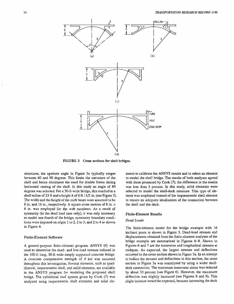
The four sections selected as promising candidates for emergency bypass bridges are shown in Figure 3. The cross sections shown in Figure 3a and b consist of a deck slab attached to a cylindrical shell. These cross sections can be cast in horizontal or vertical positions. In most instances, casting these sections in a vertical position can be accomplished in one pour; however, casting these sections in a horizontal position requires at least two pours.
In the first pour, the shell portion will be cast after the appropriate shell reinforcement and the reinforcement required to ensure continuity between the shell and the deck have been placed. During the curing of the shell portion, the form work and reinforcement required in the deck slab can be positioned By reinforcing the deck slab to act compositely with the shell, the cross sections shown in Figure 3a or b are obtained. In these two cross sections, because the deck is only supported by the shell at its crown, large bending stresses are induced at this connection.
Appropriate voids can be used (Figure 3b) to remove structurally insignificant material and thus to reduce the structure's dead weight. In Figure 3c, two thin webs are used to connect the deck to the shell. These webs reduce both longitudinal and transverse stresses in the shell-deck section despite the fact that they increase the dead weight of the structure.
The cross section shown in Figure 3d is a modified version of the one in Figure 3c. In Figure 3d, longitudinal beams are used along the edges of the shell and the deck. The beams along the shell and deck are connected by using either vertical posts or inclined members. These members could be either cast in place or precast and added before the element is transported to the field. The beams along the edges of the deck function to reduce the transverse bending stresses in the deck and to serve as curbs. Posttension tendons required to assemble the shell-deck segments can be positioned internally or attached to the edge beams along the shell.
The integrated shell-deck cross sections shown in Figure 3a, c , and d were analyzed assuming a simply supported concrete segment 100 ft long and 30 ft wide. In the analysis, the deck and the shell thickness were assumed to be 8 in. and 5 in., respectively. The deck thickness is similar to that found in segmental box-girder bridges. However, the assumed shell thickness is small in comparison with the thickness of webs and bottom flanges in segmental box-girder bridges. In shell
14 TRANSPORTATION RESEARCH RECORD 1180
t " l_
R
(a) ( b)
(c)
R
( d)
FIGURE 3 Cross sections for shell bridges.
structures, the aperture angle in Figure 3a typically ranges between 60 and 90 degrees. This limits the curvature of the shell and hence eliminates the need for double fonns during horizontal casting of the shell. In this study an angle of 80 degrees was selected For a 30-ft-wide bridge, this resulted in a shell radius of 23 ft and a height h of 6 ft 11/2 in. (see Figure 3). The width and the height of the curb beam were assumed to be 8 in. and 16 in., respectively. A square cross section of 8 in. x 8 in. was employed for the web members. As a result of symmetry (in the dead load case only), it was only necessary to model one-fourth of the bridge; symmetry boundary conditions were imposed on edges 1 to 2, 2 to 3, and 2 to 4 as shown in Figure 4.
Finite-Element Software
A general-purpose finite-element program ANSYS (6) was used to determine the dead- and live-load stresses induced in the 100-ft long, 30-ft wide simply supported concrete bridge. A concrete compressive strength of 4 ksi was assumed throughout this investigation. Several elements, such as quadrilateral, isoparametric shell, and solid elements, are available in the ANSYS program for modeling the proposed shell bridge. The cylindrical roof system given by Cook (7) was analyzed using isoparametric shell elements and solid ele-
ments to calibrate the ANSYS results and to select an element to model the shell bridge. The results of both analyses agreed with those presented by Cook (7); the difference in the results was less than 3 percent. In this study, solid elements were selected to model the shell-deck structure. This type of element was employed instead of the isoparametric shell element to ensure an adequate idealization of the connection between the shell and the deck.
Finite-Element Results
Dead Loads
The finite-element model for the bridge example with 16 inclined posts is shown in Figure 5. Dead-load stresses and displacements obtained from the finite-element analyses of the bridge example are summarized in Figures 6-9. Shown in Figures 6 and 7 are the transverse and longitudinal stresses at midspan. As expected, the largest stresses and deflections occurred in the cross section shown in Figure 3a. In an attempt to reduce the stresses and deflections in this section, the cross section in Figure 3a was reanalyzed by using a wider shelldeck connection. The maximum transverse stress was reduced by about 33 percent (see Figure 6). However, the maximum deflection was slightly increased (see Figures 8 and 9). This slight increase would be expected, because increasing the deck

Fanous el al.
\sYlt4ETRY
FIGURE 4 Boundary conditions for bridge.
FIGURE 5 Finite-element model of shell-deck structure.
1000 ~------------------~ Sec. 3a (narrow connection)
800 §!c..:.l.2...~d..!..~!!!i::lli>.cl. _
~~.v~~JL ~11£· ~_(Ii, i!J.C!Jrl4!_d .£l~f~ -
~· .. ~.(1~.!~IJ~.~.P.!?~!;;) ... 1 ~'-~·-·-···-· ··-·· 600
400
200
0
-200 ~---~-~--~---~-~--~~ 0 m ~ w oo m ~ ~ ~ ~
DISTANCE FROM CENTER TO EDGE (in.)
FIGURE 6 Transverse stresses across the deck (midspan).
and shell connection increases the dead weight of the section and does not significantly increase the stiffness of the cross section. Deflections obviously can be reduced by reducing the dead weight of the cross section by using appropriate voids as shown in Figure 3b. Another alternative to improve the structural behavior in Figure 3a is to use a section similar to that shown in Figure 3d. Connecting the deck to the shell by using eight diagonal members reduces the maximum transverse stress and vertical displacement by 50 and 20 percent, respectively (see Figures 6 and 8). The reduction in the transverse stress was very obvious (see Figure 6) when 16
15
Sec. 3o (Na rrow conmiclion)
<iii -400 3
§!c.:.l.2...<t:'.J~ !:2.n.!!,.ajio_cl _
~'-~·-·-···-···-· ·
~11£ ~J8_1n~li!!e.!J e.o!tsl _ .
;:?~ .~.<LlJ~.J[lS!in!!l .e.<?;;.t.s2 .... ~ -500 • • ......... ~ - --., ______ ....................... _______ _ ~ ' -- --~ -600 •-•••uh••-..:.--: .. :.:.:.:.:.: ....... :.~:: .. :.:.:.:.~::-..-·~·;; •;.: •;
s z 9 -700 -:::~-,·· ·- .. ··--···-···-···-···- .. ··
'--~~--~-----------800 ~-~----~--~-~----~--~~
0 m ~ w oo m ~ ~ ~ ~
DISTANCE FROM CENTER TO EDGE (in.)
FIGURE 7 Longitudinal stresses across the deck (midspan).
~
~ 0
-0.B ~----------------------,
-1.0
-1.2
-1.4
-1.6
Sec 3o. (narrow connecllon)
~'-~· · ·-·· ·-···-··
Sec. ~.verticsi!J:!2.s!L
~· ~d_(li, i!J.C!Jri'!_ci.£l~f~ _
~ .... ~.(1~.l~~l!~.l!!!.e~~!:i) ...
···- ···-···-···-···-···-- ···-· .. --..,··-···- ···
...J -1.B --. .__ .n.n .n .w.-.- . an...,..
-~-:::::.:::~ ·:.:·:.:·:.:·: ·:·· · ·· · · ·· · · ................. __ -----. ()
~ -2.0 r - ----------------------~---... -2.2
-2.4 .__ _ _.__ _ _._ _ __._ __ .__ _ _.__ _ __._ _ __.. _ __..____,
o m ~ w oo m ~ ~ ~ ~
DISTANCE FROM CENTER TO EDGE (in.)
FIGURE 8 Vertical displacement across the deck (midspan).
diagonal members were used to connect the deck to the shell. Doubling the number of the diagonals also reduced the vertical displacement along the edges of the deck (see Figures 8 and 9). Using vertical posts did not improve the structural behavior of the shell deck, as may be seen in Figure 3a. Using diagonal members in conjunction with the edge beams introduces truss action along the edges of the bridge. This results in reducing deflections and stresses as shown in Figures 6-9 (compare the results of Figure 3d using vertical posts or diagonals). The cross sections with a wider shell-deck connection, 16 inclined posts, and two thin webs were selected for further investigation when the bridge is subjected to live loads.
Live Loads
The previously described bridge was reanalyzed considering truck live loads recommended by the American Association of State Highway and Transportation Officials (AASHTO) (8). Live loads as defined in the AASHTO specifications were positioned on the bridge deck as shown in Figures 10 and 11 to induce maximum longitudinal, transverse, and shear stresses. However, because of the limitations imposed by the finiteelement idealization, the lane loads for the load case that induces maximum shear stresses were applied along the nodes

16
-0.B
-1.0
'C' = iz
-1.2
w ~ -1.4 w u
~ -1.6 IQ 0 _j -1.B <! u ~ -2.0 w >
-2.2
-2.4 0
Soc. 3a (narrow oonnoction)
~..J2Jwid2.,2~~.J2cl.._ Sec. 3c -···-···- ···- ···- ··
Sec. ?.il!!_v~~JL
~- ~d_(~ i~c!ki~ _p£s.t.s)_
~~ ... -~.(W. !~.slJ~.!!9. . .P.~~f:s) ..
···-···-···-···-·- ·····-····- ···-···- ···- ···
------------- ~--~ -------..._ --ID W ~ ~
ANGLE OF APERTURE FROM CENTER TO EDGE (deg.)
FIGURE 9 Vertical displacement across the shell (midspan).
rs· 1. 10· 10' T s·.I
'*''"'''tl PLUS LINE LOAD AT MIDSPAN
PLUS LINE LOAD AT MIDSPAN
.5 ' 10' 2. 5 . 2 . 5' 10' 2. 5 '
' 11 H ~ 111111 PLUS LINE LOAD NEAR SUPPORT
~ '
I ,,,.,~ PLUS LINE LOAD AT MIDSPAN
I. 15 ' f' 15' I FIGURE 10 Arrangement of lane loads.
adjacent to the support and not on the nodes above the support. For the finite-element model, quarter symmetry was used when the load cases shown in Figure lOa, b, and c were analyzed. This idealization may appear incorrect for the load case that produces maximum shear stresses (see Figure lOc). However, to compensate for the errors that resulted from placing the line load near the support and not above it, equal line loads must be applied at a similar distance from the other end. These loads will induce the miscalculated fraction of the shearing force at the near support that resulted from misplacing the line loads along the location described earlier. Hence, quarter symmetry still can be used for the analysis of this particular load case. The entire bridge system was modeled for the analysis of load case lOd.
TRANSPORTATION RESEARCH RECORD 1180
.0 .0 .0 .0 .0 .0
8 8 0 8 0 0 "' "' 0 0 0 "' 0 "' 0 "' "' ~ "' ~ CXl .., .., ..,
t 14'
I VARIABLE I t 12.5'
I 12.5' l
(a) (b)
ACTUAL TRUCK LOAD MODIFIED TRUCK LOAD
50' 50 '
l.2.5' 12.5 '
(c)
(d)
2 .5' 2.5'
(e) ·-·-t ·-·~-·--+·-·•
---1>-- . • . --- .
·-+·-·+ . ·- · ·-·· "'
(f)
FIGURE 11 Arrangement and magnitude of truck loads.
The bridge considered herein was also reanalyzed considering AASHTO truck loading (8). Figure 11 shows the location of trucks for each of the four loading cases analyzed Note that the loads per each axle as well as the distance between the axles are not equal (see Figure lla), and hence one must idealize the entire structure for the finite-element analysis. However, to minimize the computation time and to make use of symmetry conditions, some modifications to the truck loading were necessary. This was accomplished using a simple beam analysis considering a modified truck load that predicts the same maximum bending stresses as the actual truck loading. The modified load obtained from this analysis is shown in Figure 1 lb. This load was applied to the bridge example previously described; the results were compared with those obtained from the analysis using the actual truck loading. Differences between the results obtained using the modified loading and the actual AASHTO loading were within 2 percent, and hence it was satisfactory to replace the AASHTO truck loading with the modified loading in subsequent analysis. For the reader's interest, using the modified load in conjunction with a quarter symmetry resulted in saving 50 min of CPU time on the VAX 11nso computer. In summary, quarter symmetry was employed in the analysis of the load cases shown in Figure llc and d, half symmetry was used to

Fanous el al.
analyze load case 1 le, and the entire structure was modeled to analyze load case 1 lf. The actual truck loading and the assumption that the axles are 12 ft apart were employed in the analysis of the load case shown in Figure lle.
The results of the analyses of the bridge example demonstrated that the truck-load cases yielded larger displacement and stresses than those induced by lane loads. The maximum displacement because of any of the foregoing live loadings, however, was less than that allowed by the AASHTO specifications, that is, was less than 1/800 of the span of the bridge.
0.2
0
? = ~
-0.2
w as -0.4
j -0.6 0...
-... ···--···--···-···- ···-··· ------ ..._ __ ._ ___ _ IQ 0 _J -0.8 -<{ u
~ -1 -Sec 3c (wide connection)
~..:.-3.9...<Ji!D!i!k!!l~·~ -1.2
Sec,}.£ ..... ·- ··-···--1.4 -
-40 -30 -20 - 10 0 10 20 30 40
ANGLE OF APERTURE FROM CENTER (deg.)
FIGURE 12 Distribution of vertical displacements caused by loads shown In Figure llf.
5000
4000 -= Sec. 3a (wide connection)
VI ._s. (/) 3000 (/) §.8£· Jc_ - .,. - - - - -w g: (/)
_J 2000 <{ z iS ~ 1000 G z 9
0
-1000 .__ ____ ..___ ____ ....___ _ ___ _,___ ____ _,
0 10 20 30 40
ANGLE OF APERTURE FROM CENTER TO EDGE (deg.)
FIGURE 13 Distribution of longitudinal stresses across the bridge sections for load self-weight and loads shown in Figure lld.
17
Figure 12 shows the displacement distribution across the bridge at midspan for the live load shown in Figure 1 lf to the three different cross sections shown in Figure 3a, c, and d As can be seen, the cross section without webs or inclined posts to connect the deck to the shell experiences large differential displacements between the two edges. However, connecting the shell to the deck significantly increases the torsional behavior of the section.
The results of the analyses of the load cases shown in Figure 11 demonstrated that the bridge with inclined posts experiences stresses and displacements bounded by those induced in the cross sections built with and without thin webs. This is shown in Figures 12 and 13. Maximum longitudinal stress induced by applied live loads and dead loads of the structure is given in Table 1. Also listed are those stresses calculated using a flexure stress analysis. The data illustrate that the cross section without posts or thin webs experiences the largest stresses despite the fact that this section weighs less than the others. In addition, it may be noted that the heaviest cross section, that is, the one with thin webs, experiences smaller displacement and stresses (see Figures 12 and 13). Because of the similar behavior of the cross section with inclined posts and the cross section with thin webs (see Figures 12 and 13), the cross section with inclined posts was selected for additional investigation.
SUMMARY AND CONCLUSIONS
Closing a bridge for repair or maintenance always causes inconvenience to the traveling public. Shell elements with an attached deck slab for emergency bypass bridges were analytically investigated. Several cross sections that can be utilized for these types of bridges were initially studied, and a subset of four was selected for further investigation. These cross sections consist of a deck slab attached to a shell element at its crown over a wide or a narrow connection and shell-deck elements connected by either inclined truss elements or by two thin webs. The finite-element technique was employed to perform the analysis of a simply supported bridge built considering these three different shell-deck sections.
The results demonstrated that shell bridges can be used to construct short- or medium-span emergency bridges. The displacements and transverse and longitudinal stresses caused by the structure self-weight and the live loads were influenced by connecting the deck to the shell. The cross section with inclined posts connecting the deck to the shell was found to be the most appropriate section for this new bridge concept. In addition, these sections were constructed using a procedure
TABLE 1 LONGITUDINAL STRESS NEAR EDGE OF SHELL CAUSED BY SELF-WEIGHT AND TRUCK LOAD
Centroidal Rexural Inertia Axis from Finite Stress
Area (in.4) Bottom Weight Element Analysis Section (in.2) x lo'3 (in.) (lb/ft) (psi) (psi)
Wide connection 4,935 1,382 58.55 4,%9 4,700 4,705 Inclined post 5,012 1,756 58.95 5,212 3,800 3,850 Two thin webs 5,724 2,374 53.75 5,764 2,740 2,785
NoTE: See Figure l ld.

18
similar to that used in building small bridges and culverts utilizing air-bag forms.
ACKNOWLEDGMENT
This research investigation was supported by the National Science Foundation. However, the results reported here are those of the authors and do not reflect the opinions of the sponsor.
REFERENCES
1. C. F. Galambos. Bridge Design, Maintenance and Management Public Roads, Vol. 50, No. 4, March 1987.
2. D. P. Billington. Thin Shell Concrete Structures. McGraw-Hill, New York, 1965.
TRANSPORTATION RESEARCH RECORD 1180
3. A. M. Hass. Precast Concrete-Design and Applicalions. Applied Science Publishers, New York, 1983.
4. S. Timoshenko and S. Woinowsky-Krieger. Theory of Plates and Shells. McGraw-Hill, New York, 1978.
5. Contractor's Concrete Advantage. Concrete Construction Institute, Addison, ID., 1986.
6. G. J. DeSalvo and J. A. Swanson. ANSYS Engineering Analysis System User's Manual. Swanson Analysis System, Inc., Houston, Pa., 1985, Vols. 1 and 2
7. R. D. Cook. Concepts and Application of Finite Element Analysis, 2nd ed. John Wiley & Sons, New York, 1981.
8. Standard SpeciftcaJions for Highway Bridges, 13th ed. American Association of State Highway and Transportation Officials, Washington, D.C., 1983.
Publication of this paper sponsored by Commillee on General Structuns.
Related Documents