Analytical Computation of Multiple Interference Fits under Elasto-Plastic Deformations Gerd Wachsmuth, Michael Lätzer and Erhard Leidich August 8, 2013 Abstract Multiple interference fits represent high friction-stressed shaft-hub connections. High surface pressures together with thin-walled intermediate parts lead to high stresses and showing strong tendencies to plastic deformations. Cylindrical inter- ference fits and their elasto-plastic behaviour have been analysed in the literature. However, in the case of multiple interference fits, these methods are not applicable. In this paper, we derive a new calculation method for elasto-plastically deformed multiple interference fits with hardening material. The analytical method is vali- dated by the comparison of the determined stresses and displacements of several test cases with the solutions of corresponding axisymmetric finite element models. 1 Introduction A widespread type of shaft-hub connections are interference fits. Due to their versatile capabilities they are often used to transfer large torsional moments. In many applications it is sufficient to consider interference fits consisting of two parts. However, in some cases multiple interference fits consisting of three or more rings have to be used, e.g., for the connection of machine shafts with a hollow-shaft gearbox. In this case a multiple interference fit with four parts is applied in order to connect both shafts due to a frictional connection. In practice, shrink discs are used for such attachments, see RINGSPANN [2009]. In order to transfer high torsional moments, one has to consider not only elastic de- formations but also plastic deformations of the material. Unfortunately, the calculation of an elasto-plastic stressed multiple interference fit is currently not possible without the numerical solution of nonlinear partial differential equations (PDEs). The aim of this contribution is to derive a simple analytical method to compute the displacements and stresses of an elasto-plastic multiple interference fit. Our method requires the solution of a nonlinear system of equations, see Eq. (12), which is possible using Newton’s method. Note that this computation does involve the computation of definite integrals, see Eq. (9), 1

Welcome message from author
This document is posted to help you gain knowledge. Please leave a comment to let me know what you think about it! Share it to your friends and learn new things together.
Transcript
Analytical Computation of MultipleInterference Fits under Elasto-Plastic
Deformations
Gerd Wachsmuth, Michael Lätzer and Erhard Leidich
August 8, 2013
Abstract
Multiple interference fits represent high friction-stressed shaft-hub connections.High surface pressures together with thin-walled intermediate parts lead to highstresses and showing strong tendencies to plastic deformations. Cylindrical inter-ference fits and their elasto-plastic behaviour have been analysed in the literature.However, in the case of multiple interference fits, these methods are not applicable.In this paper, we derive a new calculation method for elasto-plastically deformedmultiple interference fits with hardening material. The analytical method is vali-dated by the comparison of the determined stresses and displacements of severaltest cases with the solutions of corresponding axisymmetric finite element models.
1 Introduction
A widespread type of shaft-hub connections are interference fits. Due to their versatilecapabilities they are often used to transfer large torsional moments. In many applicationsit is sufficient to consider interference fits consisting of two parts. However, in some casesmultiple interference fits consisting of three or more rings have to be used, e.g., forthe connection of machine shafts with a hollow-shaft gearbox. In this case a multipleinterference fit with four parts is applied in order to connect both shafts due to a frictionalconnection. In practice, shrink discs are used for such attachments, see RINGSPANN[2009].In order to transfer high torsional moments, one has to consider not only elastic de-
formations but also plastic deformations of the material. Unfortunately, the calculationof an elasto-plastic stressed multiple interference fit is currently not possible without thenumerical solution of nonlinear partial differential equations (PDEs). The aim of thiscontribution is to derive a simple analytical method to compute the displacements andstresses of an elasto-plastic multiple interference fit. Our method requires the solution ofa nonlinear system of equations, see Eq. (12), which is possible using Newton’s method.Note that this computation does involve the computation of definite integrals, see Eq. (9),
1
but avoids the solution of ordinary or partial differential equations. Note that some partsof this work were published (in German) in an abbreviated form, see Leidich et al. [2010].
2 State of the scientific and technical knowledge
Multiple interference fits The computation of (multiple and ordinary) interferencefits is based on the equations of the theory of thick-walled pipe theory. The study ofthick-walled pipes was initially motivated by military applications and by the design ofcontainers for extrusion. Friedewald was one of the first who deals with equations tocompute the principal stresses and pressures as a function of the joint assembly sequencefor the elastic multiple interference fit, see Friedewald [1957]. Kienzle and Grüningdetermined the elastic stresses in extrusion containers experimentally and analytically.Using photoelasticity, they studied the influences of geometric discontinuities and ofthermal stresses, see Kienzle and Grüning [1961]. In “Der SKF Drucköl-Preßverband”one finds a short explanation to compute a three-part multiple interference fit with athin-walled intermediate part by using the equations of a two-part interference fit, seeSKF [1990]. A method for short interference fits and three-part multiple interferencefits, which are exposed to a non-constant axial surface load and a temperature field, isdeveloped in Blok [2006].None of these references deals with plastic deformations of multiple interference fits.
Up to our knowledge, there is no method allowing the analytical solution of multipleinterference fits if plastic deformations occur.
Interference fits The displacements and stresses of an elasto-plastic interference fitwith two rings can be computed without the numerical solution of partial differentialequations. All of the following methods rely on the computation of elasto-plastic thick-walled pipes, which are loaded by either an outer or an inner pressure. Hence, thesemethods are not applicable if plastic deformations occur in the intermediate parts of anmultiple interference fit, since they are loaded by an inner and an outer pressure.Lundberg provided a basis for elastic and elasto-plastic interference fits by using the
von Mises yield criterion in order to determine the equivalent stresses and strains, seeLundberg [1944]. Gammer and Lance published a method to compute an elasto-plasticshrink fit by using the Tresca yield criterion combined with a linear elastic, perfectly plas-tic or a linear elastic, linear hardening material behaviour, see Gammer and Lance [1982].Önöz considered elasto-plastic interferences fit and developed an analytical method forlinear elastic, non-linear hardening material by using the Tresca yield criterion, see Önöz[1983]. In 1983, Kollmann and Önöz developed a theory to compute elasto-plastic inter-ference fits with a modified Tresca’s yield criterion assuming a linear elastic, perfectlyplastic material behaviour, see Kollmann and Önöz [1983]. Baldanzini developed a semi-analytical approach using the von Mises criterion in order to determine the equivalentstresses and strains in interference fits with an user defined material, see Baldanzini[2004].
2
3 Derivation of the analytical solution
Given the geometry of the interference fit (i.e., the radii and interferences) as well as theouter and inner pressures, we want to compute the displacements of the rings and thepressures in the joints. In the case where all rings are in the elastic regime, the solutionis well known and standard. Moreover, analytical solutions for the plastic behavior ofa single interference fit exists, see Section 2. We want to derive an analytical solutionfor the plastic behavior of a multiple interference fit. To this end, we give an analyticalrelation between the displacements of a single ring and the pressures acting on its innerand outer surfaces, see Section 3.1. This relation is used in Section 3.2 to derive acalculation method for a multiple interference fit.
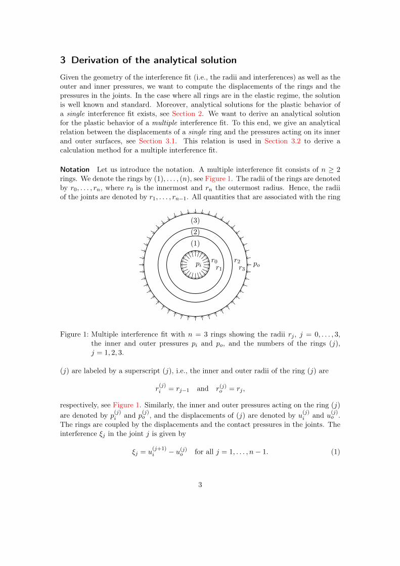
Notation Let us introduce the notation. A multiple interference fit consists of n ≥ 2rings. We denote the rings by (1), . . . , (n), see Figure 1. The radii of the rings are denotedby r0, . . . , rn, where r0 is the innermost and rn the outermost radius. Hence, the radiiof the joints are denoted by r1, . . . , rn−1. All quantities that are associated with the ring
r0r1
r2r3
(1)
(2)
(3)
pi po
Figure 1: Multiple interference fit with n = 3 rings showing the radii rj , j = 0, . . . , 3,the inner and outer pressures pi and po, and the numbers of the rings (j),j = 1, 2, 3.
(j) are labeled by a superscript (j), i.e., the inner and outer radii of the ring (j) are
r(j)i = rj−1 and r(j)o = rj ,
respectively, see Figure 1. Similarly, the inner and outer pressures acting on the ring (j)
are denoted by p(j)i and p(j)o , and the displacements of (j) are denoted by u(j)i and u(j)o .The rings are coupled by the displacements and the contact pressures in the joints. Theinterference ξj in the joint j is given by
ξj = u(j+1)i − u(j)o for all j = 1, . . . , n− 1. (1)
3
The case of a clearance fit in the joint j can be modelled by ξj < 0. The contact pressurein the joint j is denoted by pj , j = 1, . . . , n − 1. Moreover, the multiple interference fitis subject to an inner pressure pi and an outer pressure po. It is convenient to use thenotations p0 = pi and pn = po.
3.1 The elasto-plastic ring
In this section we derive an analytical solution for the deformations and stresses of anelasto-plastic ring. For simplicity, we omit the superscript (j). We use the followingassumptions in order to derive an analytical relationship between the displacements ui,uo and the pressures pi, po:
(i) the setting is axisymmetric,
(ii) no axial stress at the outer radius r = ro, i.e., σz(ro) = 0,
(iii) elastic behaviour at the outer radius r = ro with Young’s modulus E and Poisson’sratio ν,
(iv) the volume change is independent of r, i.e., εr + εθ + εz = const,
(v) there is no warping of the cross-section, i.e., εz = const,
(vi) we use the von Mises criterion to determine the equivalent stresses and strains,
(vii) there are no shear stresses and strains, i.e.,
σrθ = σrz = σθz = 0,
εrθ = εrz = εθz = 0,
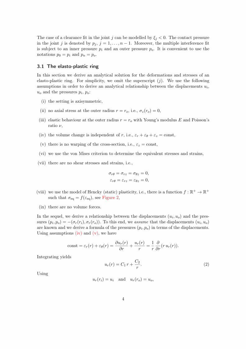
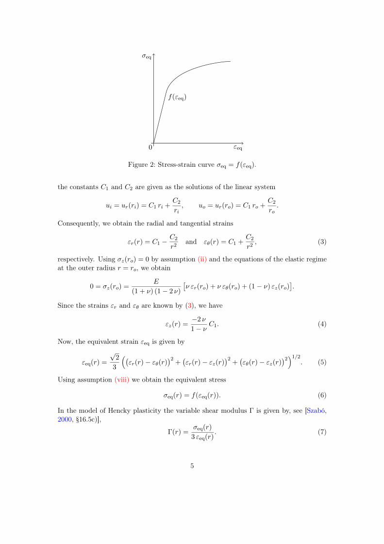
(viii) we use the model of Hencky (static) plasticity, i.e., there is a function f : R+ → R+
such that σeq = f(εeq), see Figure 2,
(ix) there are no volume forces.
In the sequel, we derive a relationship between the displacements (ui, uo) and the pres-sures (pi, po) = −(σr(ri), σr(ro)). To this end, we assume that the displacements (ui, uo)are known and we derive a formula of the pressures (pi, po) in terms of the displacements.Using assumptions (iv) and (v), we have
const = εr(r) + εθ(r) =∂ur(r)
∂r+ur(r)
r=
1
r
∂
∂r(r ur(r)).
Integrating yields
ur(r) = C1 r +C2
r. (2)
Usingur(ri) = ui and ur(ro) = uo,
4
σeq
εeq0
f(εeq)
Figure 2: Stress-strain curve σeq = f(εeq).
the constants C1 and C2 are given as the solutions of the linear system
ui = ur(ri) = C1 ri +C2
ri, uo = ur(ro) = C1 ro +
C2
ro.
Consequently, we obtain the radial and tangential strains
εr(r) = C1 −C2
r2and εθ(r) = C1 +
C2
r2, (3)
respectively. Using σz(ro) = 0 by assumption (ii) and the equations of the elastic regimeat the outer radius r = ro, we obtain
0 = σz(ro) =E
(1 + ν) (1− 2 ν)
[ν εr(ro) + ν εθ(ro) + (1− ν) εz(ro)
].
Since the strains εr and εθ are known by (3), we have
εz(r) =−2 ν
1− νC1. (4)
Now, the equivalent strain εeq is given by
εeq(r) =
√2
3
((εr(r)− εθ(r)
)2+(εr(r)− εz(r)
)2+(εθ(r)− εz(r)
)2)1/2. (5)
Using assumption (viii) we obtain the equivalent stress
σeq(r) = f(εeq(r)). (6)
In the model of Hencky plasticity the variable shear modulus Γ is given by, see [Szabó,2000, §16.5c)],
Γ(r) =σeq(r)
3 εeq(r). (7)
5

Consequently, the stress-strain relations imply
σr(r)− σθ(r) = Γ(r) (εr(r)− εθ(r)). (8)
By the equilibrium of stresses we infer
∂σr∂r
(r) =1
r(σθ(r)− σr(r)) =
1
rΓ(r) (εθ(r)− εr(r)).
Integration over [r, ro] yields
σr(r) = σr(ro)−∫ ro
r
1
rΓ(s) (εθ(s)− εr(s)) ds. (9)
The unknown stress σr(ro) can be determined by using assumptions (ii) and (iii). Theequations of the elastic regime at the outer radius r = ro and σz(ro) = 0 imply
σr(ro) = σr(ro)− σz(ro) =E
1 + ν(εr(ro)− εz(ro)). (10)
Now, the pressures pi and po in dependence of the displacements ui and uo are given by
pi = pi(ui, uo) = −σr(ri) and po = po(ui, uo) = −σr(ro), (11)
where σr(ri) and σr(ro) are determined by (9) and (10), respectively. Note that theevaluation of pi and po does not require the solution of any differential equation, onlythe integral in (9) has to be computed (numerically).
3.2 Multiple Interference Fit
In this section we explain, how the results of the previous section for a single ring canbe used to calculate the pressures and displacements in the entire multiple interferencefit. Let us assume that the inner and outer pressures of the multiple interference fitpi and po as well as the interferences ξj for each joint j, j = 1, . . . , n − 1 are given.Similar considerations can be done if for some joints the desired pressures pj insteadof the interferences ξj are given. In the previous section we derived a formula for thepressures p(j)i and p(j)o in dependence of the displacements u(j)i and u(j)o , for all rings (j),j = 1, . . . , n. Together with the coupling condition (1), we obtain the nonlinear systemof equations
p(j)i (u
(j)i , u(j)o ) = pj−1 for j = 1, . . . , n,
p(j)o (u(j)i , u(j)o ) = pj for j = 1, . . . , n,
u(j+1)i − u(j)o = ξj for j = 1, . . . , n− 1,
(12)
for the unknowns u(j)i , u(j)o , j = 1, . . . , n and pj , j = 1, . . . , n − 1. Note that the innerpressure p0 = pi and the outer pressure pn = po are given. Hence, we arrived at anonlinear system with 3n− 1 equations and 3n− 1 unknowns. This system of nonlinearequations can be solved by Newton’s method. The solution of the system (12) yields the
6
displacements u(j)i , u(j)o , j = 1, . . . , n. By using (8) and (9) the stresses σr and σθ canbe evaluated. Using arguments similar to those leading to (9), a formula for the axialstresses σz can be derived. Let us briefly highlight the changes which are necessary incase of a solid shaft, i.e. r0 = 0. In this case the inner pressure p0 = pi is unknown, butthe inner displacement of the solid shaft u(i)i is zero due to continuity considerations, i.e.,u(1)i = 0. Hence, the known inner displacement u(1)i has to be replaced by the unknown
inner pressure pi = p0. The number of unknowns remain 3n− 1.
4 The finite element model
To validate our analytical method we use the finite element software Abaqus/CAE 6.8-2.The validation process was divided into four steps. These steps differ in the number ofjoints, in the size of the radii and interferences and in the material model of the rings:
(i) finite element model of a standard interference fit with elastic behaviour,
(ii) finite element model of a standard interference fit with elasto-plastic behaviour,
(iii) finite element model of a multiple interference fit with elastic behaviour,
(iv) finite element model of a multiple interference fit with elasto-plastic behaviour.
Each step include several test cases. These test cases differ in the size of the radii, inter-ferences and in the materials of the rings. Due to the rotational symmetry of a multipleinterference fit, it is sufficient to consider a axisymmetric two-dimensional model. The in-terferences (resp. clearance fit) in the joints are modelled using the function “interferencefit” of Abaqus.In practice, the clearance fit (modelled as a negative interference) is necessary for the
assembly of two shafts (e.g. one solid and one hollow or two hollow). To realize thepositive interference, one uses a shrink disc which includes a taper interference fit. In thepractical assembly as well as in the finite element model, the interference between thetwo outer shafts is gradually increased by the shrink disc. This will cause the clearancefit (between the inner rings) to be closed once the interference (between the outer rings)is large enough. In contrast, the assembly in the analytical model is considered to happensimultaneously, since we are using the material law of Hencky (static) plasticity.Figure 3 shows the finite element model of the multiple interference fit with boundary
conditions.
5 Comparison with a numerical model
The test cases. Table 1 shows six particular test cases of multiple interference fitsconsisting of three rings with elasto-plastic behaviour. Note that the clearance which ispresent in the inner joint (ξ1 < 0) is closed during assembly by the interference (ξ2 > 0)in the outer joint. In all examples, we used a clearance fit in the inner joint since suchinterference fits are common in practice. For the test cases two materials with different
7

Figure 3: Finite element model of the multiple interference fit.
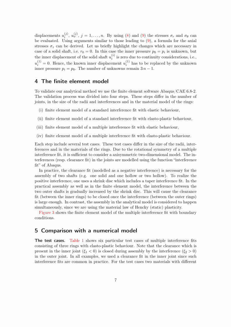
stress-strain curves are used. In the test Cases 1 and 3 we consider a tempering steelmaterial 1, whereas the construction steel material 2 is used in Case 2. The test casesk.1, k = 1, 2, 3, are similar to the test cases k. They do not show a qualitatively differentbehaviour.The material parameters are
ν = 0.3, yield stress =
{949 MPa,
432 MPa,and E =
{1.95 · 105 MPa for material 1,2.06 · 105 MPa for material 2.
The function f , which describes the stress-strain curve, see assumption (viii) andFigure 2, is obtained by a static tensile test. These stress-strain curves are shown inFigure 4.
Results. The distributions of the stresses σr, σθ and σeq are shown in Figure 5 andFigure 6 for Case 2 and Case 3, respectively. In test Case 2 plastic deformations occurin the thin-walled intermediate part. In Case 3, plastic deformations occur in the innerand outer rings of the multiple interference fit, whereas the middle ring is elasticallydeformed. The analytically and numerically obtained stresses are almost identical. Inparticular the radial stresses at the joints (i.e. the joint pressure) match very well. Therelative errors in the radius of the zone of plasticity stay below 2% and the relative errorsin the stresses stay below 3%. However, large relative errors occur in the axial stressesin the zone of plasticity. This is shown in Figure 7. In this figure we have detailed thezone of plasticity in the outer ring. The radial displacements for Case 3 are shown in
8
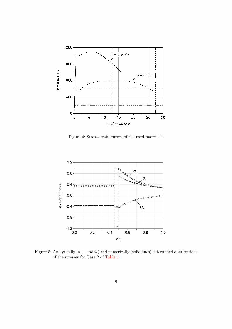
Figure 4: Stress-strain curves of the used materials.
Figure 5: Analytically (◦, + and 3) and numerically (solid lines) determined distributionsof the stresses for Case 2 of Table 1.
9
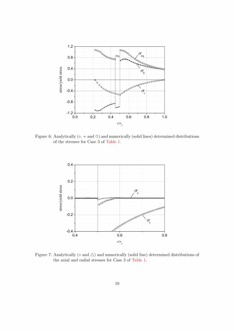
Figure 6: Analytically (◦, + and 3) and numerically (solid lines) determined distributionsof the stresses for Case 3 of Table 1.
Figure 7: Analytically (◦ and 4) and numerically (solid line) determined distributions ofthe axial and radial stresses for Case 3 of Table 1.
10
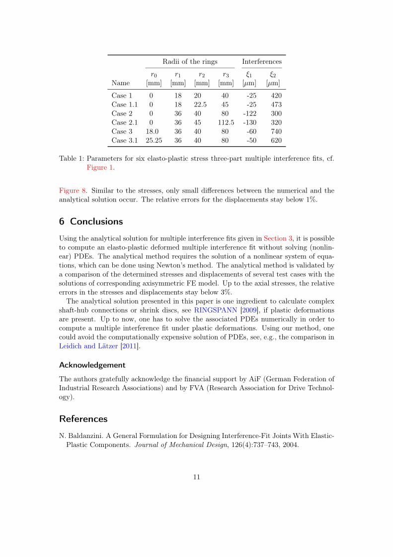
Radii of the rings Interferences
r0 r1 r2 r3 ξ1 ξ2Name [mm] [mm] [mm] [mm] [µm] [µm]
Case 1 0 18 20 40 -25 420Case 1.1 0 18 22.5 45 -25 473Case 2 0 36 40 80 -122 300Case 2.1 0 36 45 112.5 -130 320Case 3 18.0 36 40 80 -60 740Case 3.1 25.25 36 40 80 -50 620
Table 1: Parameters for six elasto-plastic stress three-part multiple interference fits, cf.Figure 1.
Figure 8. Similar to the stresses, only small differences between the numerical and theanalytical solution occur. The relative errors for the displacements stay below 1%.
6 Conclusions
Using the analytical solution for multiple interference fits given in Section 3, it is possibleto compute an elasto-plastic deformed multiple interference fit without solving (nonlin-ear) PDEs. The analytical method requires the solution of a nonlinear system of equa-tions, which can be done using Newton’s method. The analytical method is validated bya comparison of the determined stresses and displacements of several test cases with thesolutions of corresponding axisymmetric FE model. Up to the axial stresses, the relativeerrors in the stresses and displacements stay below 3%.The analytical solution presented in this paper is one ingredient to calculate complex
shaft-hub connections or shrink discs, see RINGSPANN [2009], if plastic deformationsare present. Up to now, one has to solve the associated PDEs numerically in order tocompute a multiple interference fit under plastic deformations. Using our method, onecould avoid the computationally expensive solution of PDEs, see, e.g., the comparison inLeidich and Lätzer [2011].
Acknowledgement
The authors gratefully acknowledge the financial support by AiF (German Federation ofIndustrial Research Associations) and by FVA (Research Association for Drive Technol-ogy).
References
N. Baldanzini. A General Formulation for Designing Interference-Fit Joints With Elastic-Plastic Components. Journal of Mechanical Design, 126(4):737–743, 2004.
11

Figure 8: Analytically (◦) and numerically (solid line) determined radial displacementfor Case 3 of Table 1 in dependence of the radius r.
A. A. Blok. Analytische Modellierung des Spannungszustandes mehrteiliger Querpressver-bände im Zylinder von LDPE-Höchstdruckverdichtern. Dissertation. Shaker Verlag,2006.
H.-J. Friedewald. Presspassungen für Schnitt- und Umformwerkzeuge. Number 472 inForschungsheft. VDI-Verlag, 1957.
U. Gammer and R.H. Lance. Elastisch-plastische Spannungen im Schrumpfsitz.Forschung im Ingenieurwesen, 48(6):192–198, 1982. doi: 10.1007/BF02561603.
O. Kienzle and K. Grüning. Über die Beanspruchungsverhältnisse in Blockaufnehmernvon Strangpressen. Forschungsberichte des Landes Nordrhein-Westfalen. West-deutscher Verlag, Köln und Opladen, 1961.
F. G. Kollmann and E. Önöz. Ein verbessertes Auslegungsverfahren für elastisch-plastischbeanspruchte Preßverbände. Konstruktion, 35(11):439–444, 1983.
E. Leidich and M. Lätzer. Übertragungsfähigkeit von Klemmverbindungen unter beson-derer Berücksichtigung plastischer Verformungen. FVA Abschlussbericht. FVA (Re-search Association for Drive Technology), 2011.
E. Leidich, M. Lätzer, and G. Wachsmuth. Elastisch-plastisch beanspruchte Mehrfach-pressverbände. In Welle-Nabe-Verbindungen. Gestaltung — Fertigung — Anwendun-gen, number 2114 in VDI-Berichte, pages 335–342. VDI-Tagung, October 27–28, 2010.
12

G. Lundberg. Die Festigkeit von Presssitzen. Das Kugellager, 19(1/2):1–11, 1944.
RINGSPANN. Produktinformation Schrumpfscheiben. Number RLK 608. 2009.
SKF. Der SKF Drucköl-Preßverband, 1990.
I. Szabó. Höhere Technische Mechanik: Nach Vorlesungen. Klassiker der Technik.Springer-Verlag, 2000.
E. Önöz. Die Auslegung elastisch-plastisch beanspruchter Querpressverbände unterBerücksichtigung der Verfestigung. Fortschritt-Berichte der VDI Zeitschriften, 1(108),1983.
13
Related Documents